Embed Size (px)
Citation preview
SECTION III
LEACHATE AND CONDENSATE MANAGEMENT PLAN
LEACHATE AND CONDENSATE MANAGEMENT PLAN
WAIMANALO GULCH SANITARY LANDFILL KAPOLEI, HAWAII
PREPARED BY
WASTE MANAGEMENT OF HAWAII, INC.
REVISED OCTOBER 2020
i
TABLE OF CONTENTS
1.0 Introduction ............................................................................................................... 3 2.0 Condensate ............................................................................................................... 3 3.0 Leachate Generation ................................................................................................. 3 4.0 Leachate Collection and Removal System ................................................................ 4
4.1 Leachate Collection Sumps.................................................................................... 4 4.2 Leachate Maintenance Levels ................................................................................ 4
4.2.1 Leachate Sump Pump Systems ........................................................................ 5 4.2.2 Pump Settings .................................................................................................. 5
5.0 Leachate Storage & Disposal .................................................................................... 5 6.0 Leachate Monitoring and Sampling ........................................................................... 6
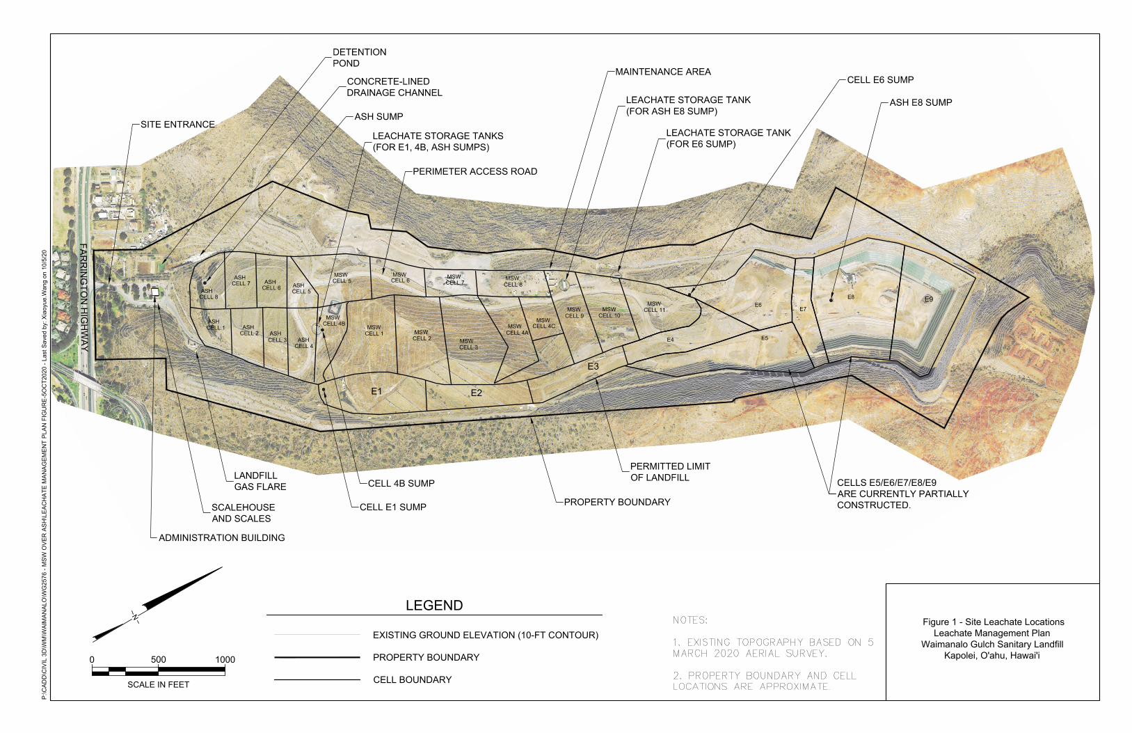
6.1 Responsibilities ...................................................................................................... 6 Figure Figure 1. Site Leachate Locations
Leachate Sump Diagrams
ii
ACRONYMS AND ABBREVIATIONS
amsl above mean sea level
BMP Best Management Practices
btoc below top of casing
DOH Department of Health, State of Hawaii
ft feet
GCCS Gas Collection and Control System
HAR Hawaii Administrative Rules
LCRS Leachate Collection and Removal System
LFG Landfill Gas
MSW Municipal Solid Waste
WGSL Waimanalo Gulch Sanitary Landfill
WMH Waste Management of Hawaii, Inc.
WWTP Waste Water Treatment Plant
3
1.0 INTRODUCTION
Waste Management of Hawaii, Inc. (WMH), has prepared this Leachate and Condensate
Management Plan to establish the standard operating, maintenance, and disposal
procedures for leachate and condensate generated at the Waimanalo Gulch Sanitary Landfill
(WGSL).
This Leachate and Condensate Management Plan is part of the WGSL Site Operations
Manual and should be used as the primary document for leachate and condensate
management at the facility.
2.0 CONDENSATE
Landfill gas condensate is a liquid produced in landfill gas collection systems. The
condensate is removed as the landfill gas is withdrawn from the landfill. Condensate is
composed primarily of water and organic compounds. Condensate management is
accomplished by sloping the landfill gas (LFG) transmission piping to a low point in the
landfill gas collection and control system (GCCS) piping for collection of the condensate. The
condensate collection sump/drain is located at this low point, to collect the condensate and
remove it from the transmission piping. The condensate collection sump and knockout vessel
are located along the gas collection header at the flare station. These systems collect and
transport the condensate through the collection header to a 12,000-gallon storage tank. The
flare is designed to allow condensate from the tank to be injected into the flare. In the case
that the condensate cannot be injected into the flare, an outside contractor pumps the
condensate out of the storage tanks and into a mobile tanker truck. The condensate will likely
be mixed in the tanker truck with leachate from one of the existing on-site leachate tanks.
The leachate/condensate mixture is then transported to a City and County of Honolulu Waste
Water Treatment Plant (WWTP) for disposal.
3.0 LEACHATE GENERATION
Leachate is generated when water percolates through disposed refuse. This percolation can
occur when precipitation infiltrates directly into the waste, or when moisture in the refuse
(whether present when landfilled or generated after landfilling as a product of bio-
decomposition) filters or leaches out.
Leachate generation is minimized by using the following best management practices (BMPs)
at the WGSL:
• Maintaining positive drainage on top of the landfill to minimize infiltration. Storm
water runoff from covered areas of the landfill is directed to down drains/swales
that will carry the runoff to the stormwater detention basins. Precipitation that falls
on the active face is managed there and not directed off the landfill.
• Use of geosynthetic tarps in active filling areas. These tarps prevent rainfall and
storm water from infiltrating the waste cells and reduce the potential for erosion.
4
• Maintaining surface water drainage around the perimeter of the landfill to prevent
surface water run-on into the active disposal area.
4.0 LEACHATE COLLECTION AND REMOVAL SYSTEM
All disposal areas (Ash and Municipal Solid Waste [MSW] cells) constructed at the WGSL
are equipped with a bottom and side slope composite liner and leachate collection and
removal system (LCRS) that meets Federal (Subtitle D equivalent) and State of Hawaii
Administrative Rules (HAR) 11-58.1-14 requirements. Subtitle D regulations require that
leachate not be allowed to accumulate on the landfill bottom liner to a depth of more than 30
centimeters (approximately 1 foot), not including that contained in collection sumps.
A description of the liner systems that are in place at the WGSL are detailed in Section II
WGSL Operations Plan of this Site Operations Manual.
4.1 LEACHATE COLLECTION SUMPS
There are five leachate collection sumps at the WGSL
• Ash Sump, collects leachate from ash monofill cells 1 through 8;
• MSW Cell 4B sump, collects leachate from MSW cells 5 through 11
• MSW Cell E1 Sump, collects leachate from MSW cells E1through E4;
• MSW Cell E6 sump, collects leachate from ash monofill cells E5, E6 and E7; and
• Ash Cell E8 sump, collects leachate from ash monofill cells E8 and E9.
See the attached Figure for leachate sump locations.
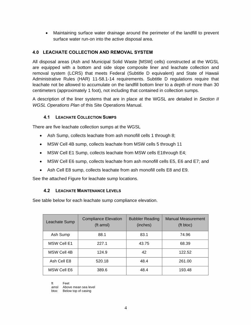
4.2 LEACHATE MAINTENANCE LEVELS
See table below for each leachate sump compliance elevation.
Leachate Sump Compliance Elevation
(ft amsl)
Bubbler Reading
(inches)
Manual Measurement
(ft btoc)
Ash Sump 88.1 83.1 74.96
MSW Cell E1 227.1 43.75 68.39
MSW Cell 4B 124.9 42 122.52
Ash Cell E8 520.18 48.4 261.00
MSW Cell E6 389.6 48.4 193.48
ft Feet amsl Above mean sea level btoc Below top of casing
5
4.2.1 Leachate Sump Pump Systems
The leachate sump pump systems consist of automatic pumps, flow meters, pressure
transducers (except for Ash Sump), and bubbler systems. The instrumentation automatically
starts, stops, and modulates pump speeds to efficiently and reliably pump variable flow rates.
The pump systems utilize electric submersible leachate pumps, a submersible electronic
pressure transducer, and a bubbler system. The pressure transducer and the bubbler system
are used to monitor the leachate levels (in inches) in the sumps. The pressure transducer
provides the primary level control while the bubbler is a backup/secondary system.
The pump controls are configured to pump the leachate level down to as close to the riser
base plate as possible without causing air intrusion into the pump. The pumping systems
automatically maintain a specified flow rate based on the leachate levels in the sumps up to
the maximum capacity of the pump. Each leachate pump system can display alarms and
shutdowns, which are indicated by a red flashing light located on top of the control panel
enclosure. Electrical power is supplied to each system by Hawaiian Electric Company.
4.2.2 Pump Settings
With the pump selector switch in the “automatic” position, the leachate level in the sump will
rise until it reaches the user specified “pump on” level, which will start the pump. The pump
will then continue to run until the user specified “pump off” level has been reached. Pump
flow rates are also specified by the user. Pump level settings are set to maintain less than
one foot of head on the liner system.
At sumps Ash, E1, E6, and E8, the status of the pump system is indicated by lights (green,
amber, red) located on top of control panel. If the pump is running the green light indicator
will blink. If the leachate level in the sump rises above the pump start point, but is below the
user specified high level, the amber warning light will blink, indicating a pump or flow
problem. If the level further rises to a point above the user specified high-level alarm, the red
alarm light will blink, indicating an alarm or fault condition.
Manual operation at a user specified flow rate can also be started at any time by placing the
pump selector switch in the “hand” position. An outside electrical contractor handles repairs
or maintenance activities that need to be performed on the leachate pump systems or
associated equipment.
5.0 LEACHATE STORAGE & DISPOSAL
Leachate that is pumped out of the riser sumps is temporarily stored on-site in 20,000-gallon
steel frac tanks. There are currently five (5) 20,000-gallon steel frac tanks on-site. Three of
the frac tanks are located on the MSW 4B cell, and are attached to the E1 leachate sump,
the 4B sump, and the Ash sump. These three leachate storage tanks are situated within the
limits of the landfill waste footprint (lined area), which, in the event of a spill or release,
provides secondary containment. The other two leachate storage tanks are attached to sump
6
E6 and the Ash E8 sump and are maintained with lined secondary containment basins.
These tanks are proposed to be moved to a bermed area on the MSW 4B cell that is situated
within the landfill footprint.
An outside contractor pumps the leachate out of the storage frac tanks and into a mobile
tanker truck. The leachate is then transported to a City and County of Honolulu WWTP for
disposal. The contractor measures and records the quantity (gallons) of leachate pumped out
of the storage tanks and hauled off-site for disposal. These quantities are maintained as part
of the sites operating record. Pumping the leachate directly to the sewer system for disposal
is being proposed.
6.0 LEACHATE MONITORING AND SAMPLING
The leachate riser pump systems are monitored weekly. The leachate data is recorded on
the monthly Leachate Logs for each sump. Data collected includes the level of leachate in
the sum, volume of leachate in each tank, and any comments or observations noted.
Annually a third-party consultant conducts leachate sampling activities in conjunction with the
site’s groundwater monitoring program. WGSL groundwater and leachate monitoring
activities are conducted pursuant to the WGSL Groundwater and Leachate Monitoring Plan
(Geosyntec, 2016) located in Section VII of this Site Operations Manual.
6.1 RESPONSIBILITIES
WGSL Site Manager has overall responsibility for implementation of this Plan and all
operational activities related to leachate management. The Site Manager manages and
interfaces with outside contractors and treatment facilities, schedules the necessary tank
trucks required to manage leachate, and ensures that observed deficiencies are corrected
and documented in a timely manner.
Waste Management Environmental Professional works with the Site Manager to ensure that
leachate levels in the sumps are maintained and kept in compliance with permit and
regulatory requirements. They coordinate the annual sampling and analytical testing of
leachate and ensures that the required reports are submitted to the Hawaii Department of
Health (DOH) and leachate treatment facilities (when necessary). The Environmental
Professional is the point of contact for regulatory agencies and handles permit compliance
issues and notifications to the DOH, as necessary.
FIGURE
E9E8
MSWCELL 10
MSWCELL 11
MSW
MSWMSW
MSWMSW
MSWMSWMSWASH ASH
ASHASH
ASHASH
ASH
ASHCELL 8CELL 7CELL 6CELL 5
CELL 4BCELL 4A
CELL 3CELL 2
CELL 1
CELL 8
CELL 7CELL 6 CELL 5
CELL 4CELL 3
CELL 2CELL 1
E2E1
E5
E7
MSW
MSW
CELL 4C
E3
MSWCELL 9
E4
E6
SITE ENTRANCE
ADMINISTRATION BUILDING
DETENTIONPOND
CONCRETE-LINEDDRAINAGE CHANNEL
ASH SUMP
SCALEHOUSEAND SCALES
LANDFILLGAS FLARE CELL 4B SUMP
CELL E1 SUMP
LEACHATE STORAGE TANKS(FOR E1, 4B, ASH SUMPS)
PERIMETER ACCESS ROAD
PROPERTY BOUNDARY
PERMITTED LIMITOF LANDFILL
MAINTENANCE AREA
LEACHATE STORAGE TANK(FOR ASH E8 SUMP)
LEACHATE STORAGE TANK(FOR E6 SUMP)
CELL E6 SUMP
CELLS E5/E6/E7/E8/E9ARE CURRENTLY PARTIALLYCONSTRUCTED.
ASH E8 SUMP
FAR
RIN
GTO
N H
IGH
WA
Y
N
0 500 1000
SCALE IN FEET
P:\C
AD
D\C
IVIL
3D
\WM
\WA
IMA
NA
LO\W
G25
76 -
MS
W O
VE
R A
SH
\LE
AC
HA
TE M
AN
AG
EM
EN
T P
LAN
FIG
UR
E-5
OC
T202
0 - L
ast S
aved
by:
Xia
oyue
.Wan
g on
10/
5/20
Figure 1 - Site Leachate LocationsLeachate Management Plan
Waimanalo Gulch Sanitary Landfill Kapolei, O'ahu, Hawai'i
EXISTING GROUND ELEVATION (10-FT CONTOUR)
PROPERTY BOUNDARY
CELL BOUNDARY
LEGEND
LEACHATE SUMP DIAGRAMS
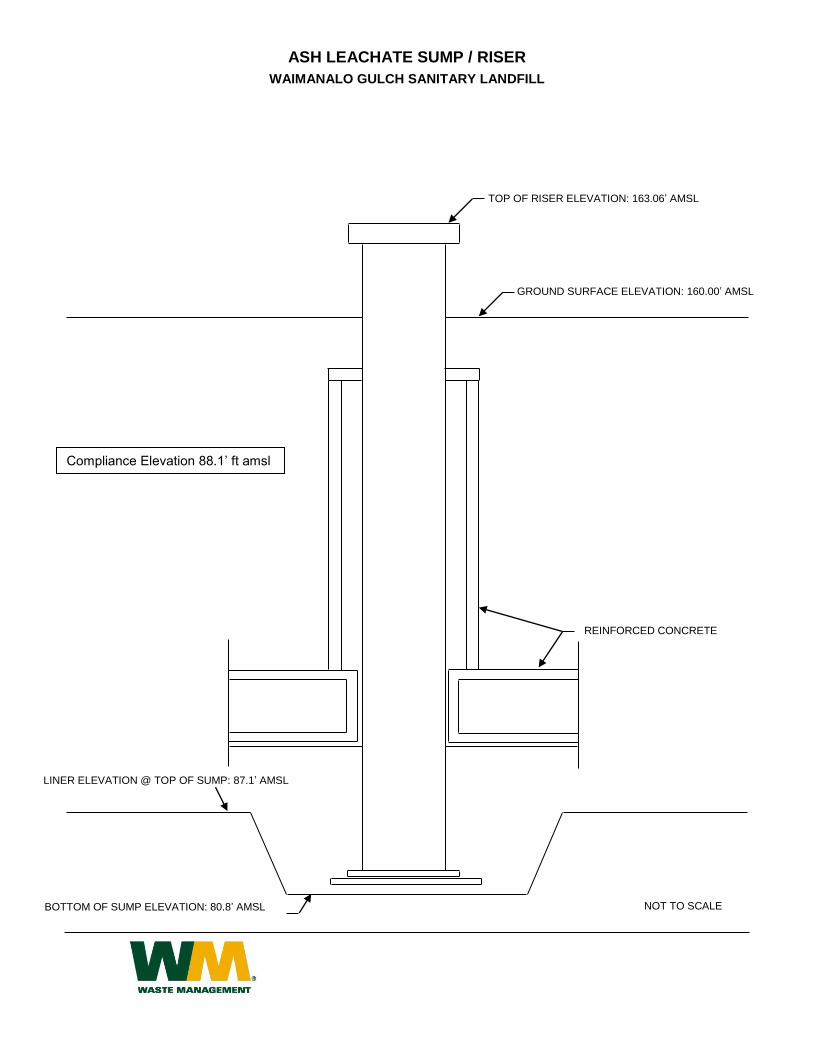
ASH LEACHATE SUMP / RISER
WAIMANALO GULCH SANITARY LANDFILL
TOP OF RISER ELEVATION: 163.06’ AMSL
LINER ELEVATION @ TOP OF SUMP: 87.1’ AMSL
GROUND SURFACE ELEVATION: 160.00’ AMSL
BOTTOM OF SUMP ELEVATION: 80.8’ AMSL
REINFORCED CONCRETE
NOT TO SCALE
Compliance Elevation 88.1’ ft amsl
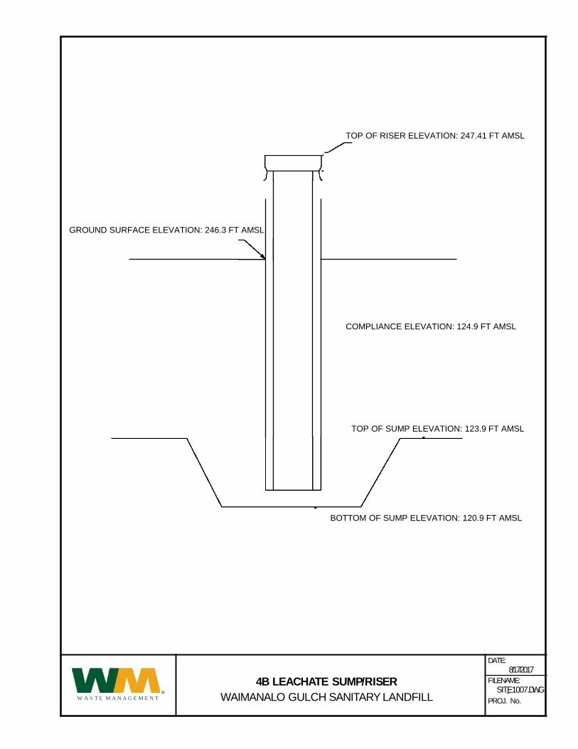
4B LEACHATE SUMP/RISER
WAIMANALO GULCH SANITARY LANDFILL
DATE:
8/17/2017
FILENAME:
SITE1007.DWG
PROJ. No.•
W A S T E M A N A G E M E N T
TOP OF SUMP ELEVATION: 123.9 FT AMSL
TOP OF RISER ELEVATION: 247.41 FT AMSL
GROUND SURFACE ELEVATION: 246.3 FT AMSL
BOTTOM OF SUMP ELEVATION: 120.9 FT AMSL
COMPLIANCE ELEVATION: 124.9 FT AMSL
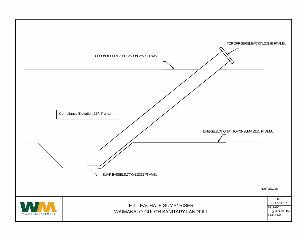
TOPOFRISERELEVATION:258.86 FT AMSL
GROUNDSURFACEELEVATION:255.7 FT AMSL
LINERELEVATIONATTOPOFSUMP:226.1 FT AMSL
E 1 LEACHATE SUMP/ RISER
WAIMANALO GULCH SANITARY LANDFILL
'\ SUMP BASEELEVATION:223.1FT AMSL
NOTTOSCALE
DATE::
8/17/2017
eW A ST E M A N A G E M E N T
FILENAME:
SITE1007.DWG
PROJ. No.
Compliance Elevation 227.1’ amsl
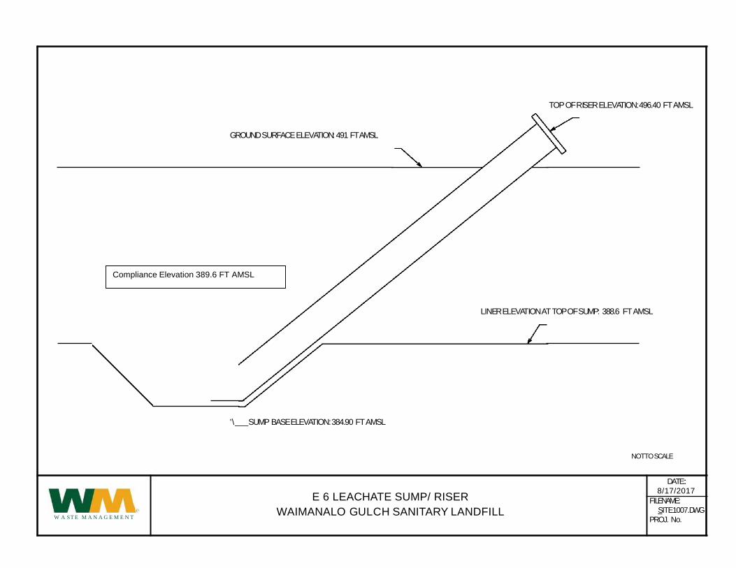
TOPOFRISERELEVATION:496.40 FT AMSL
GROUNDSURFACEELEVATION:491 FT AMSL
LINERELEVATIONATTOPOFSUMP: 388.6 FT AMSL
E 6 LEACHATE SUMP/ RISER
WAIMANALO GULCH SANITARY LANDFILL
'\ SUMP BASEELEVATION:384.90 FT AMSL
NOTTOSCALE
DATE::
8/17/2017
eW A ST E M A N A G E M E N T
FILENAME:
SITE1007.DWG
PROJ. No.
Compliance Elevation 389.6 FT AMSL
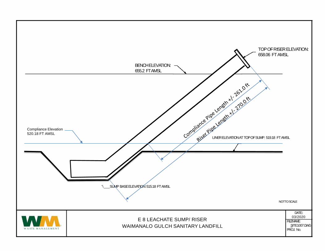
LINERELEVATIONATTOPOFSUMP: 519.18 FT AMSL
E 8 LEACHATE SUMP/ RISER
WAIMANALO GULCH SANITARY LANDFILL
'\ SUMP BASEELEVATION:515.18 FT AMSL
NOTTOSCALE
DATE::
03/2020
eW A ST E M A N A G E M E N T
FILENAME:
SITE1007.DWG
PROJ. No.
Compliance Elevation
520.18 FT AMSL
BENCH ELEVATION:
655.2 FT AMSL
TOPOFRISERELEVATION:
658.06 FT AMSL