Embed Size (px)
Citation preview
INDEX
SECTION I
INTRODUCTION
1.1 CRYOGENICS 1
1.2 HISTORICAL BACKGROUND 1
1.3 CRYOGENIC REFRIGERATION METHODS 3
SECTION II
APPLICATIONS AND PROGRESS
2.1 SPACE
2.1.1 WHAT IS CRYOPUMPING? 5
2.1.2 CRYOGENICS IN SPACE VEHICLES TESTING 14
2.1.3 CRYOGENIC WIND TUNNELS 19
2.2 ROCKET AND JET PROPULSION
2.2.1 INTRODUCTION 24
2.2.2 LOX IN ROCKETRY 24
2.2.3 SLUSH HYDROGEN AS A FUTURE JET FUEL 25
2.3 CRYOSURGERY AND MEDICINE
2.3.1 CRYOSURGERY 26
2.3.2 CONDITIONS CONDUCIVE TO CRYOSURGERY 28
2.3.3 CRYOSURGICAL INSTRUMENTATION 28
2.3.4 VISUALISATION OF CRYOSURGERY 30
2.3.5 CRYOSURGICAL INSTRUMENTS 31
2.3.6 CRYOSURGERY IN THE CURE OF PARKINSON'S
DISEASE 39
2.3.7 CRYOGENIC EYE SURGERY 42
2.3.8 CRYOSURGERY OF TUMORS 43
2.3.9 TREATMENT OF SKIN DISEASE 45
2.3.10 BLOOD AND TISSUE PRESERVATION 45
2.4CRYOGENIC ELECTRONICS
2.4.1 CRYOGENICS IN ELECTRONICS 49
2.4.2 CRYOELECTRONIC DEVICES 49
2.4.3 MASERS 52
2.4.4 JOSEPHSON JUNCTIONS POWER SUPERFAST
CIRCUITS 53
2.4.5 SQUIDS (SUPERCONDUCTING QUANTUM
INTERFERENCE DEVICES) 54
2.5 SUPERCONDUCTIVITY
2.5.1 PERFECT CONDUCTIVITY AT CRYOTEMPERATURES 58
2.5.2 SUPERCONDUCTIVITY IN ELECTRIC POWER
APPLICATIONS 59
2.5.3 POWER TRANSMISSION CABLES 60
2.5.4 ORE SEPARATION USING HTSC MAGNETS 62
2.5.5 THE MEISSNER EFFECT AND FLUX PINNING 65
2.5.6 MAGNETIC LEVITATION VEHICLES 66
2.5.7 ZERO FRICTION SUPERCONDUCTING BEARINGS 67
2.5.8 SUPERCONDUCTING MAGNETIC ENERGY STORAGE 71
2.6 CRYOMANUFACTURING
2.6.1 CRYOGENICS IN MODERN MANUFACTURING 73
2.6.2 LN2 CRYOGEN AS A CUTTING FOR PRECISION
GRINDING 73
2.6.3 CRYOGRINDING FOR SCRAP RUBBER RECYCLING 74
2.6.4 CRYOGENIC SHRINK FITTING 75
2.6.5 FABRICATION OF PRESSURE VESSELS 76
2.6.6 ADVANTAGES OF CRYOMANUFACTURING 76
2.7CRYOPRESERVATION
2.7.1 INTRODUCTION 78
2.7.2 LIQUID NITROGEN SYSTEM FOR FOOD TRANSPORTATION 79
2.7.3 CRYOGEN FREEZING & STORAGE OF FISH & SHELLFISH 80
2.7.4 CRYOPRESERVATION OF PLANTLETS AND LIVING CELLS 81
SECTION III
CONCLUSION 83
Section 1
INTRODUCTION
1.1 CRYOGENICS:
In present day usage, the word cryogenics refers to " all phenomenon, processes,
techniques or apparatus occuring or using temperatures below 120K."
Cryogenic engineering involves the development of techniques regarding practical
utilization of low temperature phenomenon both in industrial & pure science appls.
From being an interesting curiosity in the times of pioneers like Linde & Claude,
Cryogenic technology has grown into a diversified field of engineering.
The tremendous scope of cryogenics today can be gauged from the wide range of
applications that directly utilize cryogenic principles-
1.2 HISTORICAL BACKGROUND:
The chronology of cryogenic technology is summarized in the following table,
beginning with the first attempt at oxygen liquefaction & ending with the development of
High Temperature Superconductors (HTSCs).
YEAR EVENT
1877 - Calletet and Pictet liquefy oxygen
1883 - Wroblewski liquefied nitrogen and oxygen
1892 - Dewar developed vacuum insulated vessel for cryofluid storage
1889 - Dewar produced liquid Hydrogen in bulk
1902 - Claude air liquefaction system established
1908 - Onnes liquefies helium
1911 - Onnes discovers super conductivity
1916 - Commercial production of argon
1926 - First cryogenically propelled rocket test fired by Goddard
1933 - Magnetic cooling used to attained temperature below 1K
1937 - Evacuated powders used at insulation for cryofluid storage systems
1939 - First vacuum insulated railway car for cryoliquid transport buillt
1942 - V-2 weapon system test fired
1947 - Collins cryostat developed
1957 - LOX - RP -1 propelled ATLAS ICBM test fired, BCS theory for super
conductivity developed
1958 - High efficiency Multi-layer Insulation (MLI) developed
1961 - SATURN launch vehicle test fired
1966 - Dilution refrigerator using He3 - He4 developed
1975 - Record high superconducting transition temperature raised to 23K
1981 - Space shuttle using LOX launched
1986 - HTSC ceramics developed with TC = 123K
1.3 CRYOGENIC REFRIGERATION METHODS:
Absorbing or extracting heat at low temperatures and rejecting it to the ambient at
higher temperatures produces refrigeration for cryogenic applications. The three general
methods of producing cryorefrigeration in large scale applications are-
a) Liquid Vaporization Cycle
Here, a refrigerant fluid with the desired low temperature boiling point is first
compressed & condensed & then isenthalpically expanded to a low pressure./ the
evaporation of this liquid provides the desired refrigeration. .heat rejection can be
cascaded from very low temperatures to ambient levels by the use of refrigerants
with different boiling points.
b) Joule-Thompson (J-T) Expansion Cycle
In this process, a refrigerant fluid is compressed & pre-cooled to below its inversion
temperature, i.e. ,the temperature below which a reduction in pressure causes a
temperature decrease. the cold refrigerant fluid is then isentahlpically expanded to
a lower pressure to obtain the required low temperature. the low pressure fluid is
partially warmed to provide cryogenic refrigeration & then further warmed to
produce precooling.
c) Engine Expansion Methods:
In this process, a refrigerant fluid is compressed, pre-cooled & expanded to a lower
pressure through an expander to produce work to reduce both the enthalpy &
temperature.
Other refrigeration methods like use of cryocoolers provide cooling on a smaller
scale by a variety of thermodynamic cycles.
The Stirling cycle follows a path of isothermal compression, heat transfer to a
regenerator matrix at constant volume, isothermal expansion with heat absorption & finally
heat transfer from regenerator to fluid.
The Glifford-Macmahon system is a staged cryocooler that uses a displacer to reach
cryogenic temperatures.
Magnetic refrigeration uses the magneto calorific effect to produce cooling. When
ferromagnetic materials placed in a magnetic field are removed from it, their temperature
falls. Such devices are used for attaining temperatures below 1K.
2.1 SPACE
Cryopumps and cryogenic pumps are an inevitable part of space programs, from its
initial developmental phase to today's advanced phase.
What differentiates cryopumps from cryogenic pumps is that while the later is used
to pump cryogenic fluid through various devices used in space programs, former is initially
a vacuum creating device. Both these devices have been delt with in this project work.
2.1.2 What is cryopumping?
“The condensation of gas on a cryogenically cooled surface to produce vacuum is
called as cryopumping." The cryopumping phenomenon not only involves phase change
from gas to solid at cold surface but also adsorption of gas molecules. An attractive
feature of cryopumping is the extremely large cryopumping speed, which are about 106
liters/sec and higher for more large installations.
Principle of operation: -
The principle is simple. Cryogenic liquid such as liquid nitrogen or helium (Helium is
used for space application) is passed through the tubes fixed to the walls of the
cryopumping. As liquid helium passes through the tubes, the components of air such as
nitrogen, oxygen etc are condensed at the walls which are subsequently removed and we
get vacuum at that space. Liquid helium is used because it has the lowest temperature in
the cryogenic temperature scale at which every other component gets liquefied. The
cryopumps are largely used for space simulations. One such cryopump with big tubing in
NASA lab is shown in the figure 2.1.1
Types of cryopumps: -
Basically there are three types of cryopumps
i) Liquid pool cryopump
ii) Continuos flow cryopump
iii) Refrigerator cooled cryopump
Out of the above three types of cryopumps, continuos flow types is most commonly
used in many applications including space simulation.
Advantages of cryo pumping: -
Some of the advantages of cryo pumping are,
1. Clean vacuum.
2. Final pressure of less than 10-14 torr is obtainable.
3. Pumping speed per unit area is higher than that of all other pumps.
4. Extremely high pumping speed, greater than 100000 liters/sec can be produced
economically only by cryo pumps.
5. Cost of investment and operation of refrigerator cooled cryo pumps are lower than
those of all other pumps at speeds greater than 10 000 liters/sec.
Advances in cryopump technology: -
Extensive research and development is being done on the subject till date. The
latest being high efficiency, variable geometry, centrifugal cryogenic pump proposed by
the scientists at Barber Nichols Inc. Arvada.
Barber Nichols cryopump: -
The proposed pump has a basic design that is rugged and reliable with variable
speed and variable geometry features that achieve high pump efficiency over a wide range
of flow rate conditions. The pump uses a seal-less design and rolling element bearings to
achieve high reliability and ruggedness to withstand liquid vapor slugging. The pump can
meet a wide range of variable head, off-design flow requirements and maintain design
point efficiency by adjusting the pump speed. The pump also has features that allow the
impeller and diffuser blades height to be adjusted. The adjustable height blades were
intended to enhance the efficiency, when it is operating at constant head, off design flow
rates. This pump was developed for supercritical helium service, but the design is well
suited for any cryogenic application where high efficiency is required over a wide range of
head flow conditions. The assembly of the newly developed cryopump is shown is fig
2.1.2.
To minimize heat transfer into the cryogen, the pump is mounted with the motor end
above the impeller. With this design only the impeller and impeller housing are immersed
in the liquid cryo. The motor operates in warm vapor from the cryo and heat transfer from
the motor into the liquid cryo is, for the most part, limited to conduction through the pump
components.
Design concept:-
To minimize this condition heat transfer, the design uses thin walled components
for all parts that bridge the space between the warm motor and the cold pump. These
components are made of Ti-6A1-4V which has good mechanical properties at cryo
temperatures and has very low thermal conductivity (less than half of the thermal
conductivity of 304 SS).
The maximum shaft speed is 7900 rpm and the shaft is supported by rolling
element bearings at both ends of the motor rotor. The rolling element bearings are much
more robust than gas bearings that are used in other very high speed liquid helium
centrifugal pumps. Experience with this bearing design has shown that they will stand up
to shock loads associated with liquid-vapor slugging or magnet saturation.
Since the bearings are near the motor and operate in a vapor environment, grease
lubricated bearings can be used. The bearings are packed with low vapor pressure grease
so outgassing is not a problem. Bearing related maintenance is very low as the bearings
have an L-10 life and regrease interval of 50000 hrs and 8000 hrs respectively.
The entire rotating assembly is enclosed in a hermetic pump housing. This design
eliminates the need for any shaft seal, which is typically the high maintenance component
in a centrifugal pump. It also insures that the pump that the pump will not leak under either
vacuum or high pressure conditions.
The pump uses a full emission impeller with 600 backward curved blades, a vaned
diffuser section and an axial inducer. The axial inducer allows the pump t operate at its
maximum flow condition with as little as one mete of NPSH. The full emission impeller and
vaned diffuser section were designed for optimum efficiency at the 2.5 l/s, 39m head rise,
and 7900 rpm.
The pump has two features that allow it to maintain high efficiency at reduced flow
rates. The pump speed can be adjusted. The pump also has adjustable height impeller
and diffuser blades. By combining the adjustable speed and adjustable blade height

features, it is possible to cover a wide range of off-design flow conditions and maintain
relatively a high pump efficiency.
Figure2.1.3 shows that for the maximum flow condition, the pump is at its peak
efficiency and is producing exactly the head rise required to match the system head drop.
However, for the minimum flow condition, the pump is operating at about half of its peak
efficiency and it is producing 25 times the head rise required to match the system head
drop. (The excess head rise would have to be throttled across a control valve). It is
apparent that if the pump is operated at a constant speed, the low off-design efficiency
and the mismatch between the pump and system head flow characteristics will cause
excess energy to be transferred into the cryo when it is operated at low flow rates.
Testing has demonstrated that the liquid helium pump developed for the SSC
cooling system is a mechanically sound, rugged, highly reliable assembly. The design
point hydraulic performance of the pump is good and by operating the pump at variable
speed, a wide range of off-design flow conditions can be produced at design point
efficiency.
To date there is relatively limited experience in the field of LHe centrifugal pumps.
Barber – Nichols has built two LHe pump only for National Bureau of Standards (NBS),
and one for the University Of Wisconsin (UOW). The NBS LHe pump is full emission,
centrifugal pump with motor cross-coupled to the impeller. The motor runs in LHe, so all
motor losses add energy to the LHe. The UOW LHe pump is a partial emission centrifugal
pump with a 0.5m long hollow shaft between the motor and the impeller. The long shaft
effectively limits the heat transfer, but requires the bearing at the impeller, which operates
in the cryogen.
Cryopump for confined helium experiment (CHeX)
The cryopump that was sent on the space shuttle for the Lambda point Experiment
(LPE) was later redesigned for use in the confined Helium experiment (CHeX). The CHex
uses High Resolution Thermometers (HRT) to measure heat capacity within finely spaced
parallel disks. To eliminate heat flow between calorimeter and the cryogenic bath, a
cryopump is used to reduce the pressure in the experimental probe. The LPE cryopump
trapped activated charcoal behind the nucleopore filler. The new cryopump used activated
charcoal glued to the copper plates to eliminate the nucleopore filter. Vibration tests
verified that the cryopump does not generate charcoal dust contaminants. The early
performance test indicated that the probe vacuum is significantly lower with the new pump,
and that the pressure falls more rapidly than with the previous designs. Recent tests with
CHeX experimental probe show a significant reduction in the heat leaf between the
calorimeter and the cryogenic bath.
The main improvements of the LPE cryopump design were to increase the thermal
contact between the charcoal and the 1.7 K bath and to reduce the flow impedance from
the instrument vacuum space to the charcoal supply. The LPE cryopump used loose
charcoal grains trapped behind a nucleopore filter, while most cryopumps have charcoal
glued to metal plates. A pump with charcoal bonded to copper plates offers several
advantages. Each grain of charcoal is in good thermal contact with the substrate. The
charcoal-covered plates can be arranged to offer good gas conductance to the instrument.
And, since the charcoal is fixed in place, it would not be a source of contamination,
eliminating the flow impedance caused by the nucleopore filter used in the LPE cryopump.
Considering these advantages, the LPE cryopump was redesigned with charcoal glued to
metal plates using a high thermal conductivity epoxy.
The main improvement of the LPE cryopump design were to increase the thermal
contact between the charcoal and the 1.7 K bath and to reduce the flow impedance from
the instrument vacuum space to the charcoal supply. The LPE cryopump used loose
charcoal grains trapped behind a nucleopore filter, while most cryopumps have charcoal
glued to metal plates. A pump with charcoal bonded to copper plates offers several
advantages. Each grain of charcoal is in good thermal contact with the substrate. The
charcoal-covered plates can be arranged to offer good gas conductance to the instrument.
And since the charcoal is fixed in place, it would not be a source of contamination,
eliminating the flow impedance caused by the nucleopore filter used in the LPE cryopump.
Considering these advantages, the LPE cryopump was redesigned with charcoal glued to
metal plates using a high thermal conductivity epoxy.
Construction of the cryopump: -
Figures 2.1.4 & 2.1.5 show the construction features of the CHeX cryopump. The
housing holds fire copper plates coated with activated charcoal. The charcoal is
embedded in a 0.8mm thick layer of aluminum filled epoxy on both the sides of each plate.
The total plate surface area of 180 cm2 holds about 9 g. of charcoal. This epoxy was also
used to attach the plates in the charcoal plate supports. The plate assembly is stiffened by
four 1.6 mm diameter. Copper rods glued into the holes in the plates. The screen support
tube holds the plate assemblies in place inside the charcoal housing. A 100 mesh (per
inch) screen is soft soldered into a copper frame that fits lightly over the mouth of the
housing. The screen retains all larger pieces of charcoal that might escape from the
plates. The gold plated bottom radiation baffle reduces the heat radiated into the
instrument during the bake out.
Operation of the cryopump: -
Several days before the launch, seven liter instrument volume was filled with
1.3Kpa (10 torr) of He gas. This gas provided enough thermal conductivity between the
HRT flux tuber and the liquid helium bath at 1.7K to keep them below the superconducting
transition design launch. Shortly after the launch, the mechanized valve opened to allow
the probe to be evacuated through 1 m long, 6.4 mm in corrugated vacuum line. At the
same time, a heater warmed the charcoal in the cryopump to above 40 k in order to
expand the adsorbed. He gas After about five hours, the residual gas pressure was about
13 Pa (0.1 torr) and the evacuation valve was closed and the heater turned off. Then the
charcoal cooled to 2.0 K by conduction through the weak thermal link to the liquid helium
bath. The residual He gases in the probe passed through the nucleopore filter where it is
trapped by the cold charcoal. For the first 30 hours after the launch, a 3W heater was
cycled on and off to warm the liquid helium bath up to 2.0 K Increasing the instrument
temperature reduced the time required to reach the operating pressure, about 10-7 Pa (10-9
torr).
Thus, recent tests with CHeX experimental probe show a significant reduction in
heat leak between the calorimeter and cryogenic bath. The pump has also shown better
performance characteristics compared to LPE pump.
Cryogenics in space vehicle testing: -
Introduction:-
The space vehicles carrying the spacecraft are sometimes required to undergo
orbital and space exploration flights. Hence space simulation should provide actual
ignition, restart and full-scale combustion tests under near space conditions compared to
conventional environmental changes where the space crafts are tested. Testing of rockets
under simulated altitude experience tests article leakage, out-gassing, large heat release,
highly corrosive propellants, very high exhaust volume flows. These loads make it
impossible to provide the required altitude simulation, for this type of test with any single
pumping systems are combined and manipulated.
Space simulation: -
Cryogenic pumping offers high speed, which is essential for space simulation due
to larger volume of chamber and high flow rate of gases during operation. Apart from
pumping for pressure simulation, cryogenics is also used for thermal balance simulation
and cooling of exhaust diffuser in rocket engine testing. Nearly perfect vacuum is required
for true space simulation.
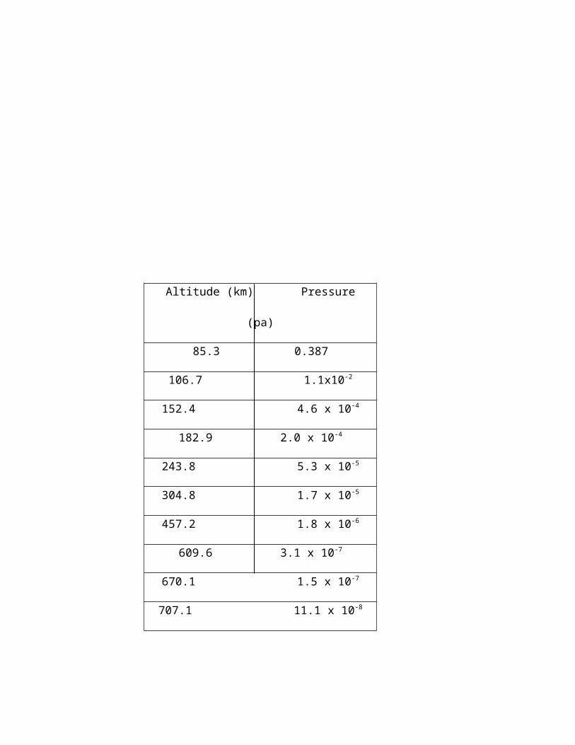
Following chart gives the presently accepted values for pressure at various
attitudes
Altitude (km) Pressure (pa)
85.3 0.387
106.7 1.1x10⁻²
152.4 4.6 x 10⁻⁴
182.9 2.0 x 10⁻⁴
243.8 5.3 x 10⁻⁵
304.8 1.7 x 10⁻⁵
457.2 1.8 x 10⁻⁶
609.6 3.1 x 10⁻⁷
670.1 1.5 x 10⁻⁷
707.1 11.1 x 10⁻⁸
Mechanical pumps are employed to reduce the chamber pressure to 0.1 m bar
range. Further reduction of chamber pressure is carried out by cryogenic pump or diffusion
pump.
Normally the space simulation chambers are evacuated around 1 x 10 -6 mbar (7.4 x
10-8 mtorr) to study the possibility or freezing of propellant in plumbing and also simulates
the near space condition. One-kilowatt gaseous helium refrigeration system cryopump
would be adequate for pumping large gas volumes under vacuum conditions. Although low
temperature refrigeration is quite expensive, cryopumping speeds are so great that the
cost of large scale. Cryopumping in terms of cost per liter per second may be lower than
for any other pumping system.
Though at 20 k surface remove all gases, it is difficult to maintain whole surface at
such a low temperature. It then requires extensive and costly refrigeration equipment. But
the temperatures in the vicinity of 100 K can be produced at much lower cost using liquid
nitrogen.
To maintain the temperature at 20 K, “cryopumping arrays” are used. In these
arrays, 20 K surface are protected from the radiant energy of the vehicle and the chamber
walls by shields cooled to 100 K. Since 20 K surface may receive reflected energy from
the shield surfaces, the thermal absorptivity of the shield is made as high as possible by
blackening. The shields are finished with black anodic treatment from inside or sprayed
with some “ space-quality” paint for high absorptivity.
The cryopump arrays are shown in figure 2.1.6
Rocket Engine Testing: -
The schematic of the rocket engine testing is shown in figure 2.1.7 initially is consist
of an outer chamber which surrounds an inner chamber. The inner chamber is fitted in
outer chamber by means of isolation bulkheads. Mechanical pump is employed for outer
chamber so that the vacuum can be maintained between the two chambers, which will
avoid filling of direct radiation from the atmosphere to the inner chamber.
Rocket engine is placed at the center of inner chamber. The arrangements shown
in the figure are made. To avoid heat transfer from engine to port, ”heat shield” is provided
in the chamber. For simulation of sun-radiation, “radiation lamp” is placed around the
engine. Liquid Nitrogen is supplied around the inner chamber for simulating the “black
space." Liquid Nitrogen is also supplied to the diffuser, which removes gases during firing
of the engine.
Simulation of space condition requires that the test object be surrounded with
surfaces highly absorptive to thermal radiation and emitting minimum radiation. This is
best accomplished with blackened surfaces cooled to cryogenic temperatures. These
surfaces are known as cryopannels, heat sink, or thermal shrouds.
The two cryogens used in simulation facility are cooled gaseous helium & liquid
nitrogen. Gaseous helium is required only for the cryopump whereas liquid nitrogen does
cryopumping, trapping, thermal simulation, absorbs heat from the radiating nozzles &
cools the rocket exhaust gas boundary layers. Hence the efficient operation of the system
depends upon the performance of the liquid nitrogen distribution system. The liquid
nitrogen distribution system is shown in figure 2.1.8.
The liquid nitrogen supply system for the shrouds are of two types, usually
described as
1) Flash system
2) Sub-cooler system
The flash system pumps liquid directly from the storage tank through the load, then
expands it through the valve, either directly into the tank or into a separator from which the
remaining liquid is drained into the tank by gravity & gas from flash chamber is sent for
refrigeration i.e. to convert it again into liquid nitrogen.
In the subcooler system, the liquid from the tank is taken out by the pump. It cools
the shroud & is discharged into the heat exchanger, where it exchanges heat with the
liquid nitrogen directly coming from the LN2 supply tank. The LN2 which is converted from
gaseous N2 is recirculated again. This liquid nitrogen is used to convert gaseous nitrogen
into liquid. The system thus forms a closed loop.
As can be gauged from the above, space simulation testing of space vehicles is
much more complex as compared to simple aircraft testing and that cryogenics forms a
vital & inevitable part of the space simulation program so that any future research needs to
focus on methods of making the cryosystems cheaper & less complex.
2.1.3 CRYOGENIC WIND TUNNELS:
Until recently, the problem of low test Reynolds numbers had limited the usefulness
of wind tunnels, especially at ultrasonic speeds. Perhaps the best solution to the problem
of low Reynolds number applications comes by operating a big tunnel (2x2 m test section
or larger) at relatively high pressures (upto 5 bar) & at cryogenic temperatures using
nitrogen as the test gas. The first cryogenic wind tunnel was a low speed tunnel built at the
at the NASA Langley research center in 1972. Since then, workers at research centers
around the world have started a large number of cryogenic wind tunnel projects. The most
successful tunnels have been built using skillful combination of cryogenic technology &
wind tunnel theory.
Wind tunnels have played an important part in the development of aircraft right from
the 1903 “Wright Flyer” to today’s state of the art supersonic jets, even with today’s
supercomputer supported Computational Fluid Dynamic technology, the need for obtaining
accurate experimental data from wind tunnels increases with the development of complex
aircraft structures .
Liquid nitrogen is injected into the air circuit & the resulting nitrogen gas result in
an increase of the Reynolds number by a factor of about 7 with no increase in the dynamic
pressure , while the drive power actually reduces.
Principle of operation :
Fig. 2.1.9 shows the basic principle of the cryo wind tunnel. It shows the effects of
reducing temperature on the gas properties, test conditions & drive power for a fan driven
cryogenic wind tunnel using N2 as the test gas. For comparison purposes, a temperature
of 332 K for ambient temp transonic tunnels is assumed. The left side figure shows the
properties of gas that varies with the temperature. The right hand side figure shows the
corresponding variations in he test conditions & drive power. It is clear from the figure that
as the stagnation temperature decreases, the Reynolds number increases steeply. These
curves are for the same tunnel with constant size & Mach number.
Cooling the test gas to very low temperatures increases the Reynolds by more than
a factor of 7. This increase is obtained with no increase in the dynamic pressure (model
loads) & with a large reduction in the drive power, a clause which makes cryo wind tunnels
a far more attractive choice as compared to previous methods.
NDA CRYOGENIC WIND TUNNEL:
National Defence Academy (NDA) in Japan planned to replace its old transonic
wind tunnel of the induction type with the new type of transonic tunnel which would be
used for basic research works. The preliminary study for the new wind tunnel was started
in 1981, and the cryogenic wind tunnel concept was selected for the tunnel, as the
concept also can be applied to small wind tunnels used for basic research of fluid
dynamics and aerodynamics.
The NDA cryogenic wind tunnel was designed as a fan driven, high subsonic, two-
dimensional tunnel. The free stream Mach number should at least upto 0.8 to provide
aerodynamic testing capability at a supercritical condition. The lowest stagnation
temperature of 108K was selected to avoid oxygen rich condition at any outside part of the
tunnel pressure shell. The design parameters of the tunnel are
Type closed circuit
Material of construction SUS 304, SCS 13 stainless steel
Insulation External
Cooling Liquid nitrogen
Test Gas Nitrogen
Test section size (H,W,L) 0.3 x 0.06 x 1.0 m
Mach no range upto 0.80
Contraction ratio 14:1
Total pressure upto 117 K Pa
Total temperature 108 K ambient
Running time upto 30 min
Maximum Reynolds no (1/M) 90 million
Fan type centrifugal compressor
Fan speed upto 2250 rpm
Drive motor 75 KW
LN2 tank volume 4.9 m3
The cooling method of the working gas for the present tunnel is the same method
that the NASA Langley Research Center developed. Liquid nitrogen is injected into the
circuit at the middle section of the second diffuser, which is located upstream of the
compressor as indicated in figure2.1.10. Originally the LN2 flow rate was controlled by a
manually operated needle valve.
CONSTRUCTION OF THE TUNNEL
Six nozzles for LN2 injection are placed on the circumference of the 2nd diffuser and
set 600 from each other. They are connected in two groups of three nozzles, 1200 apart.
The direction of spray of LN2 is perpendicular to that of the tunnel circuit flow.
The test section is rectangular in cross section, & has solid sidewalls & a slotted top
& bottom walls. The test section is housed in the cylindrical plenum chamber with a
diameter of 711mm. This chamber is mounted on a trolley & is drawn back to access the
test section. The construction of the chamber is very heavy & has a higher thermal
capacity than that of the test section. This difference of thermal capacities has significantly
influenced the operational efficiency of the present cryogenic tunnel. In order to avoid
excessive differences in the cooling rates between the chamber & the test section walls, a
dedicated LN2 line for precooling the plenum chamber is installed .
Since the NDA cryogenic wind tunnel was built in 1985,continual efforts have been
made to improve the cryogenic operational system & procedure, & to develop airfoil-
testing techniques at cryogenic conditions. The operational experience with further
improvement of the system showed that the cryogenic operation of the present tunnel is
relatively easy & safe except the cool down. But the cool down characteristics can be
improved by exhausting nitrogen gas from the plenum chamber during the cooldown. It
saves about 18 % of the amount of LN2 and 20% of the time for cooldown.
Preliminary airfoil testing experiments also indicate that adopting suitable wall
corrections, the present tunnel has a possibility to perform two dimensional airfoil tests
with a model of low aspect ratio. Further experimental research is however needed to
remove some of the deficiencies of the system
The chart shows the specifications of some of the world's famous cryo tunnels.
NASA developed its first cryogenic wind tunnel & this small & simple fan driven low speed
atmospheric tunnel made it possible to build the 0.3-m transonic cryo tunnel (TCT) .The
fan driven 0.3-m TCT can operate at pressures upto 6 Atm & Mach no. greater than 1.4.
Success of the 0.3-m TCT led to the decision to build a very large cyro tunnel, the
US National Transonic Facility (NTF). The NTF with a 2.5x2.5 m test section & operating
pressures can test at flight values of Reynolds no. for many configurations. In the pat 20
years, researchers in 8 countries have built over 20 cryo tunnels a of various types.
Recently a very large wind tunnel is being built in Japan at NAL. The 9 Atm 3x3 m
transonic tunnel is proposed at Sawado; thus with the improvements in hardware,
software, instrumentation & operating procedure we can expect more cryo tunnel projects
to fall by the way.
2.2 ROCKET AND JET PROPULSION
2.2.1 INTRODUCTION:
One of the best known areas in which cryogenic fluids like LOX, LH2 are used in
the field of Rocketry, with slush hydrogen being considered as the future prospect for use
in jet propulsion systems. To carry the large amounts of oxygen in gaseous form would
require very large volume low pressure containers or small volume but heavy thick walled
cylinders, both of which would go against the stringent space and weight requirements of
rockets. Hence, liquid oxygen (LOX) is used, it being 700 times denser than gaseous
oxygen and having the advantage that it can be carried in low pressure, light weight
insulated containers. To obtain the maximum thrust with the least possible mass of fuel,
the designer searches for ways by which mass may be ejected at very high velocities, ie,
by rapid burning and ejection of fuel. LOX and LH2 produce a large amount of thrust and
hence are obvious choices for rocket fuels.
2.2.2 LOX IN ROCKETRY:
Thrust is produced in a rocket engine by the combustion of fuel for which an
oxidizer is required, oxygen being the natural choice. The rocket cannot depend upon the
atmosphere to provide the required oxygen and hence it must be carried on the rocket
itself.
The first long range successful rocket, the German V-2 Rocket Bomb used 5000kg
of LOX as its oxidizer and 3700kg of Alcohol as the fuel and had a maximum range of 200
miles.
Almost all designs from then on have used separate LOX and fuel tanks from which
the fuel and oxidizer are piped separately to the combustion chamber. In the 60s NASA,
developed design in which the fuel and LOX chambers formed the skin of the rocket to
save weight, while others use the LOX piping to cool the combustion chamber.
2.3 CRYOSURGERY AND MEDICINE
2.3.1 INTRODUCTION
Cryosurgery is the destruction of tissue by freezing. Modern Cryosurgical
techniques were first introduced in the mid 1960's but they only achieved modest
application in selected medical specializations. Newer advances in cryosurgical devices
and Magnetic Resonance Imaging have great promise in making cryosurgery a primary
therapeutic modality.
The goal of cryosurgery is to destroy cells within a limited diseased area and to
allow the complete recovery of surrounding cells. Cooling of tissue with a cryoprobe
occurs via conductive heat transfer. When a cryoprobe is in contact with tissue, an ice
front advances in a radial direction away from the probe to form a cryolesion. The growth
of the cryolesion is incremental and well controlled. Frozen tissue is white in appearance
and is hard to the touch, clearly delineating it from unfrozen tissue. It is common to create
a cryolesion beyond the margins of the desired treatment area to ensure exposure of
unwanted cells to the coldest possible temperature.
After freezing, the tissue is left in place to thaw. The tissue dies predominantly by a
septic necrosis and is absorbed or sloughed by the body.
Characteristics of cryosurgery
The most important characteristics of cryosurgery are
- any tissue can be destroyed from the skin to bone
- any quality of tumor can be destroyed
- the loss of blood during the procedure is minimal or absent
- the possibility of using of cryoprobe avoids large incisions for deep organs
- one of the most important characteristic of cryotherapy is its painlessness (the cold
is itself an anesthetic)
- the quantity of cryodestruction can be controlled because it is exactly proportional
to quantity of freezing
- it is safe. The edge of cryodestruction is precise without damage to adjacent tissue
- though the rules for the applications must be rigorously followed, yet cryotherapy is
simple to apply
- it is rapid. It is possible to make a transurethral cryotherapy in 30 min
- it is possible with thermocouple and impedance to document the intensity of
cryodamage
- it is reversible at the initial stage; this is important in any field, especially in
neurosurgery.
- it is possible to know before, during and after the treatment where the
cryodestruction will finish
- one of the most important characteristic of this treatment is that the scar is not
retractive. This is especially important for the skin, the urethra, the prostate, the
bronchus and so on.
Basic science studies have important implications of cryosurgical devices and
procedure development.
1. Cells in the treated region should be subjected to the highest cooling rate possible
or at least to a cooling rate for cell survival. For most invasive cryosurgical
procedures, probes must be introduced in the body warm. To achieve the
necessary cooling rates, cryosurgical devices should be developed with high
cooling capacity to achieve a rapid cool down.
2. Minimum temperature achieved should be -200 c or lower.
3. Thawing should be carried out at the slowest rate possible or natural rate that can
be achieved in the body.
4. Repeated freezes should be carried with a complete thaw in between freezes.
5. Because heat transfer occurs, conductivity probe contact must be maximized to
assure the highest possible cooling rate and deepest penetration of lethal
temperature.
6. Multiple probes may be placed within a single surgical sight to ensure exposure of
the tissue to the greatest cooling rate possible.
2.3.3 CRYOSURGICAL INSTRUMENTATION
The two current methods by which low temperature are achieved in cryosurgery are
the circulation of liquid nitrogen to a probe or the expansion of high pressure gases (J - T
systems) such as Nitrous Oxide or Argon.
Liquid nitrogen systems circulate the coolant to vacuum insulated probe. In early
liquid nitrogen devices, Liendenfrost boiling often occurred in the tip which severely
hampered heat transfer and probe surface cooling. With lekdenfrost boiling, a warm
gaseous film forms between the liquid nitrogen and the inner surface of the probe
effectively insulating the tip. Complex staged sub cooling devices have been built that
overcome this problem and allow colder probe surface temperature (-130 to -1400c).
However, this significantly increases the cost and complexity of the device. Further,
because the coolant is liquid nitrogen, large storage tanks are required. This limits the
ability to reduce the size of the device. Also, circulation of the cold liquid from the tank to
the probe causes cooling of the entire conduit. This creates the need for bulky insulation
and large inflexible hoses. Finally the liquid nitrogen is consumed during use and must be
continuously replenished. This creates convenience problems related to storage and
replacement of liquid nitrogen and also creates the opportunity to run out of coolant during
a procedure.
Other currently available cryosurgical systems operate on the J-T principle. These
systems utilize a single compressed gas (for example, Nitrous oxide or Argon) to cool a
probe through the J-T effect. Because cooling occurs the majority of the cooling can be
focused at the tip, eliminating some insulation requirements. However to generate probe
surface temperature below -1000c under biological heat loads, high press (2000+ psi) are
required which creates safety problems. Even temperatures as warm as -600C require
pressure of 800 psi. Similar to liquid N2 the coolant is exhausted during use and must be
continually replenished. Finally the performance of these devices during the use decays as
the bottle pressure decreases.
Mixed gas J-T devices may circumvent the problems associated with current
technologies and allow the development of a safe, low temperature, cost effective, and
convenient device. By using mixture of gases, as opposed to a single gas, the non-ideal
properties of the coolant are increased. This results in a greater J-T effect, such that lower
temperatures and greater power can be achieved at lower pressures. Thus the advantage
of J-T based systems which includes low cost, compact size, focussed cooling and
flexibility can be combined into a system that achieves the necessary operating
temperature for tissue destruction at safe pressures. With lower working pressures, a
compressor can be incorporated into a mixed gas system reducing replenishment needs
and reliability concerns.
2.3.4 VISUALIZATION OF CRYOSURGERY ULTRASOUNDS
Freezing of tissue can be clearly visualized using ultrasound. The frozen tissue is a
solid mass and the ice font reflects a significant fraction of the acoustic waves. This
creates a bright white light at the interface between frozen and unfrozen tissue. The
remainder of the frozen tissue appears as dark region behind the hyperchoic line and is
referred to as a post acoustic shadow.
MRI
Like ultrasound, the growth of the ice ball can be clearly visualized using MRI.
There is no effective signal from the frozen region because the T relaxation interval is
sufficiently short. Subsequently the cryolesion appears black. It has been demonstrated
that mathematical model for temperature distribution within a cryolesion can be utilized to
obtain MRI assisted numerical solutions to the energy equations. In this manner the
thermal history within the cryolesion can be clearly mapped.
2.3.5 CRYOSURGICAL INSTRUMENTS
A NOVEL CLOSED LOOP CRYOSURGICAL DEVICE:
A novel cryosurgical device has been developed that dramatically improves the
cost, convenience, safety and effectiveness of cryosurgical devices. The device
incorporates a mixed gas J-T stage. The fluid mixture is non-flammable, non toxic, non
corrosive, environmentally safe, and therefore suitable for medical applications. The
system is compressor driven, utilizing a novel oil free motor. Working temperature of -115
to -1250C at pressure of 300 to 350 psi are achieved. Approximately 20 W of refrigeration
is delivered at -1200C.
The compressor console is portable having a 4 cu-ft volumetric footprint. The
cryoprobe has a handle 3.5 cm O. D. and 18cm shaft having a 4mm O. D. and a 3.5 cm
freeze zone. In bench top studies using tissue simulating media (2% gelatin, 98% saline)
ice balls of 3.5-4.0 cm diameter and 5 cm length with a mass of 48gms are created.
Studies using half calf liver tissue in body temperature water bath show ice balls of similar
size and mass (3.5 cm diameter, 48 g). In lice goat animal studies, surface temperature of
-1150C were achieved and ice balls of 3-8 cm in diameter were created in 10 min in the
liver. Isotherms below -200 C were developed at 12mm radial distance from the probe.
SYSTEM
Design criteria for the system were 15-20 w of refrigeration at -1200C with a
maximum pressure of 350 psi. Two stages were required to achieve the desired cooling
capacity. With no precooling, given the limits of the compressor technology to be
employed , the maximum refrigeration power yield was 9 W at
-1200C. However, with approximately 20W of pre cooling at -300C, this refrigeration power
increases to 28W at -1200C. The first stage, or pre cool stage, incorporated a novel oil
free compressor and a novel gas mixture. The compressor had a unique electromagnetic
line or drive mechanism and gas bearings and a size of approximately 0.6 cubic feet. The
overall size of the integrated precooler compressor and gas mixture compressor is 2.3 cu-
ft.
The power of the system was tested using a heater mode of Nichrome wire which
was wound around the freeze zone to a known resistance. A DC power supply was used
to provide current. The device was operated until the temperature reached a steady state
and the power output of the heater was increased until temperature began to rise.
GAS MIXTURES
Gas mixture combinations were computer modeled using an algorithm that
optimizes a unitil less number termed the (H*) min. Conceptually this number provides a
relative assessment of the amount of refrigeration power a gas mixture has available to
extract heat from tissue for a given amount of heat exchange capacity.
CRYOPROBE:
The cryoprobe was constructed by encasing heat exchangers in a metallic shell.
The shell was subsequently evacuated to 10E-6 Atm to provide insulation. The metallic
shell had a handle section and a shaft section. The heat exchangers of the two stages
were integrated into the handle section, which had an O. D. 3.5cm, and a length of 18cm.
The shell was 4mm outer diameter and 10cm in length and had a copper freeze zone or
tip, at the distal end 3.5 cm in length and 4mm O. D. Braided stainless steel tubing was
used to carry gas from the compressor the cryoprobe.
Soldering of adjacent stainless steel tubes and mandrill winding constructed parallel
tube counter flow heat exchangers. For the pre cool stage, the high-pressure gas mixed
tube was soldered to low pressure gas mixture tube subsequently transitioned to a counter
flow parallel tube heat exchanger from the second stage. At the end of the second stage
heat exchanger, the high and low pressure tubes transitioned into a coaxial construction
that carried the gas down the shaft and to the freeze zone. A capillary tube restriction
orifice was placed at the end of the high-pressure coaxial line allowing the gas mix to
expand within the tip.
RESULTS:
In design of a cryosurgical apparatus, the two most important criteria are probe
surface temperature and cool down rate. The probe surface temperature determines the
size of the ice ball created and the isothermal gradients within the ice ball. Most cells are
destroyed at -200c and in some cases temperature of -400c is required. When treating
tissue, it is important to achieve this necrotic temperature at the desired depth of
penetration or at the margin of a tumor, making surface temperature a critical factor.
The cool down rate is also relevant to cell death. A fast cool down rate results in the
formation of intracellular ice-crystals, which increases the lethality of the technique.
Different cells require different optimal cooling rates for destruction, but in general cooling
rates above 25 0c/min are lethal. Subjecting tissue to repeated freezing increases total cell
death by increasing the ice ball size and the necrotic isothermal zone. And increasing cool
down rate at any given point in the frozen area. In addition, repeated freezing can lower
the required necrotic temperature.
This newly developed device is capable of achieving lethal temperature at radial
distance of greater than 1cm from the probe surface. Cool down rates of greater than
150c/min are seen within radial distances of 6-9mm. This data indicate that the device with
a single probe is capable of clinical treatment of small to moderately sized tumors. Further
it would be useful in other application such as cervical disease or abnormal uterine
bleeding. A multi probe device could be developed for use in large, more complex
diseases such as prostate cancer.
The two stages in this system provide a number of advantages. First, the cool down
rate is improved by increasing the overate the cooling capacity. Second, a smaller second
stage compressor. Third, contaminants that could potentially freeze out at the J-T orifice in
the tip, may first condense in the pre cooler and prevent clogging.
A small Freon refrigeration loop was integrated into the system as the pre-cooler.
Thermoelectric coolers meeting the pre cooling requirement were found to be
impracticably large, a split stream pre cooler was considered, however the overall capacity
of the current oil free compressor was too limited.
An oil free compressor was chosen to improve reliability. Due to the small diameter
tubing required to make the compact heat exchangers for the system, the low operating
temperature, and the nature of the gas mixture, oil could easily condense in the system
and cause clogging. Using an oil based compressor maximum cool time was less than five
minutes and continued to decline with successive freezes. With the oil free compressor
there is currently no limit on freeze time other than mechanical failure of the pump. Current
run times of the system well exceed the needs to complete clinical procedures.
A CRYOGENIC CATHETER FOR TREATING HEART ARRHYTHMIA:
Heart Arrhythmia is a problem for over 2 millions Americans. To date such patients
have been difficult to treat with conventional drugs or surgery. Catheter therapy has
proven to be more effective and less expensive method of the treatment, but the
electrosurgical catheters currently used are not very effective for heart arrhythmia
treatment. They have limited destructive capability, and are difficult to keep in contact with
the heart. Lesions created with electrosurgical catheters are 3-4cm diameter spheres and
lines of these spheres must be connected in order to perform some of the treatment. A
cryogenic catheter has the potential to deliver greater destructive power to the tip, allowing
larger lesions to be formed. Linear lesions are possible and the catheter tip will adhere to
the tissue during the cooling process.
To treat heart arrhythmia the cryogenic catheter must reach temperature between
100 and 150K. To be inserted through Veins, it must be 3mm in diameter or smaller and
must be able to make a blend with a 10-15mm radius. It must be about 1m in length and
must have a surface temperature above 00c along its length. For safety reasons the
maximum pressure should not exceed 3MPa. It is estimated that 10W of cooling will be
required. The refrigerant should be benign, nonflammable, nontoxic and have low ozone
depletion potential. The catheter also needs to be disposable for safety and sterilization
reasons. These requirements have led us to choose a mixed gas J-T refrigerator as the
most practical solution.
The difficulty with existing J-T system is that they are too large in size to be used for
catheter therapy. The cold head is too expensive to be disposable, and the units require
too high pressure for catheter use. The cryogenic catheter is based upon the J-T cycle
shown in fig. 1. This is a closed cycle system that does not require make-up gas at any
time. The catheter has coaxial tubes for the high and low-pressure streams with a
miniature heat exchanger and J-T orifice at the catheter tip. The high pressure is 2.5MPa.
The largest diameter is 3mm, the length is 90cm, and all but the last 10-20mm is flexible.
The gas mixture has been optimized for the required operating conditions using non-
flammable and low ozone depletion gases. Low cost techniques have been incorporated
into the fabrication of the cold tip so that each catheter can be disposable.
Cryogenic catheter system
The schematic of diagram of the catheter tip is shown in figure and details of both
the Heat Exchangers and expansion orifice is given below.
Heat Exchanger
The miniature Heat Exchanger at the cold end is fabricated by diffusion bonding
perforated plates of copper alternated with stainless steel spacers. Photos of the Heat
Exchangers are shown in fig. By diffusion of large metal sheets containing many individual
Heat Exchangers layers, large numbers of cold ends at one time, significantly reducing the
cost in order to make them disposable is made. Prototype Heat Exchanger varied in length
from 5 to 15mm. The O. D. of Heat Exchanger was 2.5mm. The enthalpy is more affected
by changes in pressure at lower pressure, so the low pressure of Heat Exchanger must
have a much lower pressure drop than the high pressure side.
Expansion Orifice:
The J-T expansion orifice shown in fig was fabricated of sintered Copper powder.
This permitted many flow channels, limited plugging problems and provided a large area
for heat transfer. Later catheters were fabricated using a single knife edge orifice and
provided similar results with much less effort.
Lumen:
A lumen is simply the tubing used for the flexible catheter pressure lines. The inner
lumen was a 1mm O. D. polyimide tube with a stainless steel reinforcing braid. The
reinforcing braid provided not only strength against the
2.5MPa pressure but also helped to reduce the possibility of kinks in the tube. The outer
lumen was a braided nylon derivative tube with a 0.25mm wall. For safety, the outer lumen
was designed to withstand the highest pressure in the system, although a ballast volume
was added to the low-pressure side to reduce the average system pressure.
Compressor:
The compressor was commercial single stage oil lubricated compressor that
required input powers from 300 to 500W. Some experiments operated two compressors
are parallel to increase the mass flow rate. Later experiments were performed using a
custom-built oil free compressor. This simplified problems with the gas mixture since
higher boiling point components.
Results:
Most experiments were performed with the catheter sitting on the bench top
exposed to ambient air. A typical experimental result can be seen in fig. The catheter is
characterized by fast cool downs and warm ups. The lowest temperature achieved was
85K with no load on cold end. Typical operating conditions were 140K with about 3W of
additional heat added to the cold end. Fig shows catheter in operation.
2.3.6 CRYOSURGERY IN THE CARE OF PARKINSON'S DISEASE:
Parkinson's disease (so called "shaking palsy"), a disease of the central nervous
system which causes tremors of the arms and legs, has been successfully treated by
cryosurgery. A special system was developed by Linde company in co-operation with Dr.
Irving S. Cooper of St. Barnabas Hospital. The probe is shown in fig is inserted through a
dime sized hole in the patient's skull into the thalmus (a mast of gray matter at the base of
the brain which controls the transmission of nerve impulses). The cannula or probe is
made up of three capillary tube
(1) an inner tube through which liquid nitrogen flows
(2) an intermediate tube, through which the vapor formed in boiling the liquid returns
from the probe tip and
(3) an outer tube, which serves as vacuum insulated expect for the tiny silver tip, only
the material in the immediate vicinity of the tip is affected. The entire cannula has
an O. D. of 0.079" (2mm) so it may be inserted easily into deep body regions.
During an operation, liquid nitrogen is introduced into the probe from a storage
Dewar, and the probe tip is initially cooled to about 140F (-100C). The temperature is
sensed by a thermocouple attached to the probe tip and the temperature is displayed on a
strip chart recorder. Control of probe tip temperature is achieved by control of the flow rate
of liquid nitrogen to the probe. When the probe tip has been cooled to 140F, the position of
the thalmus in the immediate vicinity of the probe tip freezes. The frozen area will recover
with no damage if it does not remain frozen for more than 30 sec. The probe is moved to
several locations in the search for the defective area, and the shaking stops when the
region controlling the tumors is frozen. The patient is conscious during this operation and
assists the surgeon in locating the defective thalmus region. When the region controlling
the shaking is located, it is destroyed by prolonged freezing (about 3min) at temperature
between -400F and -600 F. At the end of the freezing period the probe tip is rapidly warmed
for easy removal. The destroyed tissue (a sphere of approximately 1/4" dia) forms a cyst
after thawing and does not interfere with normal body operation.
Of the more than 200 cases treated by cryosurgery during the initial development of
the technique, over 90% achieved excellent alleviation of the symptoms of shaking and
rigidity. In the remainder, no clear cut improvement was found but in no case were there
complications or adverse affects of cryosurgery. One of the striking features of this method
of brain surgery was that there was no morbidity or neurological defects after the
operation. In many cases, the patient was allowed to get up and move around within 24 hr
after surgery.
Obviously, the control of the extent of the frozen region is quite important. The
volume of brain tissue which is frozen may by accurately control by precise control of the
probe tip temperature. In the steady state, the heat transfer rate through a spherical frozen
region of inner radius R1 and outer radius R2 is given by
****************
WhereKs = Thermal conductivity of solid (frozen) material
Kf = thermal conductivity of unfrozen material
Ti = freezing temperature
Tp = probe tip temperature
Tw = temperature of unfrozen tissue far away from probe tip.
2.3.7 CRYOGENIC EYE SURGERY:
Two applications of cryogenic techniques have been used in eye surgery: cataract
operation and correction of detached retinas. In cataract operation, lens removal is
necessary; this can be accomplished easily and safely by freezing the lens on a cold
probe tip. The frozen lens sticks firmly to the cold metal tip and can be lifted out of the way
with the probe. Danger of rupturing the lens during extraction is minimized because it is
rigid.
Accidents or other circumstances some times cause the retina to become detached
from the wall of the eyeball. The detachment produces a "blind spot" in the field of vision of
the person. To correct the detachment retina condition, a cryogenically cooled probe tip is
applied to the outside of the eyeball in the vicinity of the detachment. The reaction to the
intense cold is set up within the eye tissue, and this reaction "welds" the retina back to its
correct position. Burst of radiation from lasers have been used in this operation, because
heat, will produce the same reaction that cold produces; however the cryogenic technique
appears to be safer because there is no permanent damage to the eye tissue in cooling.
The probe tip temperature and duration of application in the detached retina
operation depend on the thickness of the eye wall and the vacularity of the affected region.
For ex., production of frozen region or lesion near the front of the eye requires shorter
times and some what higher temperature than lesion production near the rear of the eye.
Generally the temperature used in cryoprexy (cryogenic attachment of retina) range
between -5 and -600F. The time during which the probe tip is applied ranges from 2 to 5
sec. The probe is applied until a white lesion appears on the eye, when the probe must be
quickly warmed and removed. The white response usually lasts a few seconds and
disappears.
In cooperation with Dr. Charles D. Kelman, frigitronics, Inc. has developed a
cryosurgery probe for eye operation which uses a thermoelectric elements to provide
refrigeration, as shown in fig. The probe consists of a copper rod coated with teflon except
for tip. One end of the copper rod is connected to the cold side of a thermoelectric
element, and the working end of the rod is cooled by conduction for rapid warm up or the
probe tip, the current to the thermoelectric element may be reversed or a small resistance
heater attached to the probe rod may be turned on. The unit is limited to temperature
above about -400F, but this limitation is not serious because lower temperature are not
often required for eye surgery. Other probes, such as the cooper cryosurgery probe, may
be used if lower temperature are needed.
2.3.8 CRYOSURGERY OF TUMORS:
Cryogenic freezing has been used to produce necrosis (tissue death) in several
types of tumors. Electrical or chemical destruction & irradiation have been used to kill
cancerous tissue, but cryosurgery offers certain advantages - there is no bleeding to
complicate the operation & little pain is noticed during freezing .In fact, cryosurgery has
been used to relive pain in terminal cases of cancer by freezing the nerves in the vicinity of
the tumor.
Two techniques have been used in cryosurgery of tumors: 1) the insertion of probe
into the tumor & freezing from within (penetration freezing. 2) applying the probe tip to
the surface of the tumor & freezing from the outside inwards (contact freezing).
Penetration freezing is used primarily for large tumors, while contact freezing is best
suited for small or elongated tumors. Insertion of the cryoprobe has the disadvantage of
disrupting the tumor & possibly scattering the cancerous cells. This disadvantage is not
thought to be serious, because the freed cells are usually imprisoned in ice & killed before
they can spread into the normal regions. Both techniques have been used together for
operations on large, irregularly shaped tumors.
In tumor operations , temperature of -1100F or lower are used . the time of
application of the probe is not ,as critical as for eye surgery ,except for very small tumors,
the frozen tissue must be warmed up slowly for the treatment to be effective. instead of
warming the tissue externally after freezing , the probe is removed & the tissue is allowed
to thaw out naturally. To ensure death of cancerous tissue, two or more cycles of freezing
and thawing are usually necessary.
A general purpose cryosurgery probe developed by cryovac inc. is shown in the
fig. the system is well suited for tumor surgery , although it may be used for eye & brain
surgery as well .the probe needle is a three walled unit , similar to the cannula of the
Cooper cryosurgery probe ; however , no external supply of liq. N2 is required for the
cryovac inc. unit . The probe contains a miniature J-T refrigerator within the handle of the
unit . High pressure gaseous Argon (2000 psi) is supplied to the probe from a standard
gas cylinder. The gas is cooled within a miniature counter flow Heat Exchanger & is
expanded to ambient pressure through a capillary tube. The cold gas pressure to the
probe tip absorbs heat there & returns through the Heat Exchanger to the atmosphere.
Precise temperature is achieved by automatic or manual control of the gas flow rate. The
temperature of the probe tip is sensed by a thermocouple at the probe tip & is indicated by
a meter on the control console. a small heater within the probe tip is used when quick
heating is required ,as in eye surgery or retraction of the probe from a frozen tumor.
2.3.9 IN TREATMENT OF SKIN DISEASE:
Liquid N2 may be used in treatments of work and of scarring caused by acne. It is
applied by cotton swab when the lesion is touched freezing occurs almost instantly. The
aim being to initiate the formation of blister just sufficient to separate the surrounding
tissue.
2.3.11 BLOOD AND TISSUE PRESERVATION:
Much interest has been aroused by the possibility of using cryogen's for attaining
"suspended animation" or for freezing whole animals although Dr. Smith and her
coworkers at the national Institute for Medical Research in London have succeeded in
cooling hamsters to 23F at which 50 to 60% of the water in the tissue was frozen the
complete freezing and revival of a life form as complex as man or other large animal is yet
an accomplishment of the future freezing and revival of simple systems such as whole
blood and animal semen, has been accomplished. It has been found that freezing in itself
does not cause death of cells, but the effects associated with freezing can be lethal. These
effects include mechanical damage due to ice crystal formation and chemical damage
from increased salt concentration at the edge of the frozen front. These effects can be
minimized by the use of additives and by control of the cooling rate.
In freezing a biological system, several thermal regions are experienced as shown
in the cool down curve in fig. The first region involves removal of sensible heat from the
liquid may be super cooled some what (cooled below the equilibrium solidification
temperature). The second region involves removal of latent heat or freezing of the liquid
phase within the system. After solidification is completed, the final region involves removal
of sensible heat from the solid phase until steady a state is attained.
In preservation of blood or tissue it is important to cool the specimen through the
dangerous temperature range quite rapidly. This danger zone or zone of high cell mortality
lies between 32 and -700F. From the study of transient heat transfer, it is apparent that a
volume of liquid suddenly plunged into liquid nitrogen will not experience the same
temperature history throughout the volume ie the temperature will not be the some in all
parts of specimen at any instant of time. Till inner portion of specimen will cool at a slower
rate than the outer portions nearer the cooling liquid. For this reason blood samples are
kept quite small to alleviate the problem of slow cooling (and consequent cell damage) all
the central portions of the sample during freezing.
Two techniques of cryogenic blood storage have been investigated:
(1) freezing red blood cells in mixture with a protective agent and
(2) rapid freezing of whole blood to cryogenic temperature.
In first case, the plasma and the red blood cells. An additive such as glycerol is
mixed with RBC and the mixture is frozen. Because of the presence of the additive cooling
rates are not as critical as for unprotected blood. Storage temperature commonly used in
this technique range around -1100F. When the blood is needed the frozen mixture is
thawed the glycerol is removed and the RBC are given mixed with new plasma. This
method of blood storage is best suited for fairly large hospitals, because the equipment
required is generally large and complex.
The second method of blood storage involves immersing the whole blood in a bath
of liquid nitrogen to freeze the blood in less than one min at -3200F. A protective additive
such as polyvinylpyrrolidons (PVP) is often used to reduce RBC mortality. In contrast to
glycerol, PVP need not be removed from the blood before transfusion. When the blood is
needed, it is thawed as rapidly as it was frozen.
To freeze blood as rapidly as is required for low mortality of RBC, the mass of blood
sample mist be small; otherwise, the outer layer of blood exposed to the liquid N2 wound
freeze while the central portion was fluid. Two techniques have been studied to
accomplish this rapid freezing
(1) use of thin flat containers
(2) spraying small droplets of blood directly into liquid N2.
A special container for rapid blood freezing suggested in a study by the Linde
company is shown in fig. The container has thin metal walls, and the thickness of the
blood storage space within the container is small. The container is filled with whole blood,
and the entire unit is plunged into a liquid N2 bath. After the blood has been frozen, it may
be stored indefinitely without damage to RBC.
In the second method whole blood is sprayed through an atomizer directly into liquid N2
bath.
2.4 CRYOGENIC ELECTRONICS
2.4.1 INTRODUCTION
Cryogenics and especially the phenomenon of super conductivity has shown great
promise of application to electronics. Not only can totally new devices be made which can
operate at this low temperature, but many ordinary electronic devices will perform much
better when cooled to either liquid nitrogen or liquid helium temperatures.
Several elementary super conducting circuits have been developed to produce
binary memory elements, switching devices and multi vibrators for high speed computers.
The small space requirements, negligible power inputs, increased speed and high
reliability of these electronic units combined to promise significant advantages over other
types of computer components.
2.4.2 CRYOELECTRONIC DEVICES
a) CRYOTRON
Working Principle:
The CRYOTRON is an electronic device like the vacuum tube or the transistor. It
operates on the principle that its electrical resistance will be considerably different in the
normal state than in the super conducting state. This means that it can perform in much
the same way as a switch with a low resistance on position and a high resistance of
position. It uses a fact that a magnetic field will destroy superconductivity as the means for
switching from one resistance value to other. The original cryoton consisted of a state
piece of tantalum wire 0.010" in diameter called the gate, around which was rapped a
single layer of 0.002" niobium, wire called the control thus forming a magnet coil about
1/2" long. Tantalum become Superconducting in zero magnetic field at 4.4K when
immersed in liquid helium (4.2K). Hence, only a weak magnetic field is needed to cause
the tantalum to change back into its normal conductivity state. A niobium control coil which
superconducts at about 8K, the magnetic field produced by a current flowing through the
Niobium controlled wire will cause the tantalum gate wire to stop being superconductive,
while the superconductivity of the Niobium control is not affected.
b) THE FLIP-FLOP:
One simple circuit is the Bistable Multivibrator circuit, called the Flip-Flop. The flip-
flop is able to store or remember a single piece of information. It can remember a yes or
no, one or zero, on or off or any other such item of information that the designer selects.
When the circuits were built, it was found that the wire Cryotron had a number of
disadvantages. They were hard to make and handle, they had to be welded together an
operated much more slowly than transistors.
Many of these problems were overcome by thin film technology. Instead of making
each Cryotron from wire and then connecting many of them together to form an electronic
circuit, the circuit was made by spraying thin layers of metal and insulators through a
stencil on to a flat sheet of insulating material, usually glass.
c) MEMORY DEVICES
As compared to flip-flop circuits, a much simpler method of storing information is
the persistent current memory method. Several different devices use this effect, including
the Persistor, Crowe and trapped memory flux. They store or remember information by
means of a current which flows around a ring. Scientist realized that if a current can persist
in a superconducting ring indefinitely, it can be used to remember information. The
direction in which the current flows can be used to distinguish between a one and a zero.
The presence or absence of the current may also be used. These persistent current rings
may be made just as small as the stencils will permit. Together with the conductors
needed to start the current flow, and to measure it later, they can be grouped in larger
numbers to provide the memory capabilities needed for large computers.
2.4.3 MASERS:
Masers are similar to lasers, but they shine microwaves instead of light when
simulated with resonant radiation. Maser action takes place due to the phenomenon of
population inversion in the molecules. Such population inversion leads to amplification of
photons and thence to extremely bright microwave emissions. Currently masers are used
as microwave amplifiers in wireless communication systems, electronic warfare and radar,
cellular communication, base receiver filters and as very accurate clocks.
When used as ultra sensitive microwave amplifiers, the thermal noise in the vicinity
of the maser has to be kept to a minimum for which, it is cryocooled to liquid Helium (LHe)
temperatures.
Also travelling wave masers requires magnetic fields which must not very over
distance of 7 inches, for which superconducting magnets are ideally suited, the magnets
operating at LHe temperatures.
Another way in which the unique low temperature properties can be made use of is
when superconducting metal plates are placed around the region in which the field is to be
confined because the field cannot cross the superconductors.
2.4.4 JOSEPHSON JUNCTIONS POWER SUPERFAST CIRCUITS
A Josephson junction is made by sandwiching a thin layer of non- superconducting
material between two layers of superconducting material. Pairs of superconducting
electrons “ tunneling” right through the non-superconducting barrier from one
superconductor to another.
Above the critical temperature, the interaction between the two electrons is
repulsive. However, at the critical temp, the overall interaction becomes slightly attractive.
The attraction helps the electrons into a lower energy state & makes them move without
any resistance due to ionic lattice scattering.
In a Josephson junction, the barrier is very thin, 30 Angstrom or less until a critical
current is reach, a supercurrent can flow, but when the critical current is crossed and AC
under undulating voltage develops across the junction, having a frequency of 500 GHz /
milli volt.
Detection of this change from one state to another is at the heart of main
application for Josephson junction.
Digital logic circuitry can be built using Josephson junction for use in ultra fast super
conductor. The switching times of these circuits would be of the order of a few
picoseconds. Hence, such super computers would be much faster, smaller and would
create far less heat than present computers, thus lowering the cooling loads.
2.5 SUPERCONDUCTIVITY
2.5.1 INTRODUCTION
Superconductivity is the ability of some materials, at very low temperature,
characterised by
a) Perfect electrical conductivity (R = 0)
b) Zero internal magnetic induction (B=0) in the presence of an external field.
The state of zero electrical resistance ranges between 0K and the critical
temperature. Interestingly, a closed circuit consisting of superconducting elements can
sustain a persistent, resistance less current without an external source of voltage. The
advent of superconductors have revolutionized many engineering and pure science
applications, their zero energy loss ability having the potential of saving billions of dollars
lost due to energy dissipation.
Some important application of superconductors which look set to be
commercialized in the near future are listed below
i) Superconducting Electric Transmission Cables
ii) Superconducting Magnets for physics experiments
iii) Superconducting Levitation application for transport and bearings
iv) SMES (Superconducting Magnetic Energy Storage)
v) MRI (Magnetic Resonance Imaging)
vi) Magnetic Ore separation
vii) Electronic Circuits and Devices
2.5.1 SUPERCONDUCTIVITY IN ELECTRICAL POWER APPLICATIONS
Superconductivity brings to mind a phase of developing applications, predominantly
in power generation, transmission, & distribution. The most recent demonstrations of
electric power systems based on use of both HTSCs & LTSCs have been extremely
impressive & have resulted in heightened expectations for the commercialization of this
technology within the next decade.
The fuel chemical to thermal step in the whole power production process is the
least efficient and operates with a thermodynamic limit of 30 to 35%, the scope for
improvement being small. Improvements are however possible in the supply side electric
generation, transmission & demand side utilization with the use of Superconductor
integrated equipment.
SUPERCONDUCTING GENERATORS
In generators, it would be possible to replace the iron cores with superconducting
wire, which would make them lighter & lead to greater fuel efficiency. Widespread
integration of SC generators over the next 10 to 20 years, assuming an efficiency increase
of 0.8%, would lead to energy savings of about 0.1 Quads with additional savings in fuel
costs & reduced emissions.
SUPER CONDUCTING MOTORS
Motors made of superconducting wire would be smaller & more efficient. in
industrialized countries like the US, electric motors account for 64% of all demand side
consumption , with the large motors accounting for almost 50% of the above. Assuming
substantial induction of large motors having efficiency improvements of 2% (including the
refrigeration) over the next decade, the total reduced costs to retail customers would
amount to a saving of about 0.1Quads.If in the 5000 Hp motor segment,
2.5.3 POWER TRANSMISSION CABLES
High temperature superconductors are finally ready for commercial use and
applications are to be found in the electrical power supply area, for equipment such as
high-tension cables current limiters and railway transformers.
A HTSC compound consisting of bismath lead strontium calcium copper oxide (BPSCCO)
has proven to be the most promising starting material so far. However, the process of
manufacturing HTSC cables from this powdery ceramic is by no means straightforward.
First of all, the ceramic material needs to be converted into a flexible strip. The strip
conductor forms the core of the cable, which is manufactured in several stages; the
ceramic powder is injected into silver tubes several of which are then grouped into a
bundle and inserted into an additional silver tube. After that, the bundle is pressed, drawn
and rolled to form a thin layer. This is followed by three stages of annealing at 8200C
leading to the synthesis of a super conductor. In this manner, the bundle is formed into a
strip that increases steadily in length and whose flexibility can be attributed to the thin
ceramic filaments. If these filaments were any thicker, they break when bent or pulled.
Initial large scale production of the HTSC strips have taken place at Siemens Vacuum
Schmelze plant in Hanau, Germany. Development activities at Corporate Technology are
now geared toward achieving high current densities in conductors of the greatest possible
length. At present a maximum valve of roughly 40 kilo-amp per square centimeter
(KA/cm2) can be obtained. To operate competitively, however values between 50 to 100
KA/cm2 need to achieved over lengths of several hundred meters.
The first stage of development of a superconducting cables consisted of designing.
Constructing and testing a 10m long functional model of a conductor in Erlangen. The
cable consisted of four layers of bismuth strip conductor applied to the carrier to be using a
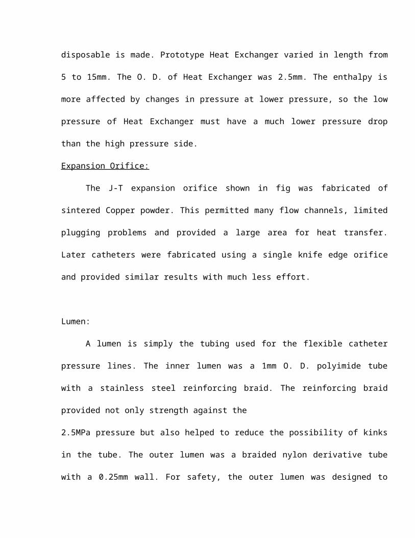
special technique for the winding the developers came up with a special recently patented
concept. A further arrangement of out bound and in bound conductors electromagnetic
fields are not produced in the vicinity of the cable path. With a total cross section of
130square millimeters (35mm2 HTSC, 95mm2 silver), the cable conductor carries a current
or 5000 amp (A). That is more than twice the rated current of a conventional 400-MVA
cable. At a rated current of 200amp the losses in a high temperature superconducting
cable amount to only 8watts per meter, even after taking into account the energy for liquid
nitrogen cooling. In contrast a copper conductor with ten times the cross section
(1200mm2) and carrying the same current would generate a loss of approximately 50
watts/meter.
The compact nature of the superconductor is just as important for the intended
applications as its low power losses. A high temperature superconducting cable of the
same cross section as conventional cable can transmit three to five times the power ideal
for regions where underground installation would prove too expensive or in which the
terrain is too difficult. In metropolitan areas high temperature superconductors could
replace the copper cables in existing cable conditions. Thus multiplying power
transmission capacity further more the high current carrying capacity of HTSC allows very
efficient power transmission at low voltages.
2.5.4 ORE SEPARATION USING HTSC MAGNETS
A separator for processing Kaolin will incorporate the largest high temperature
superconductivity magnet in terms of combined size, magnetic field and stored energy that
has ever been built. The 0.8m diameter magnet will deliver a 2.5 Tesla magnetic field and
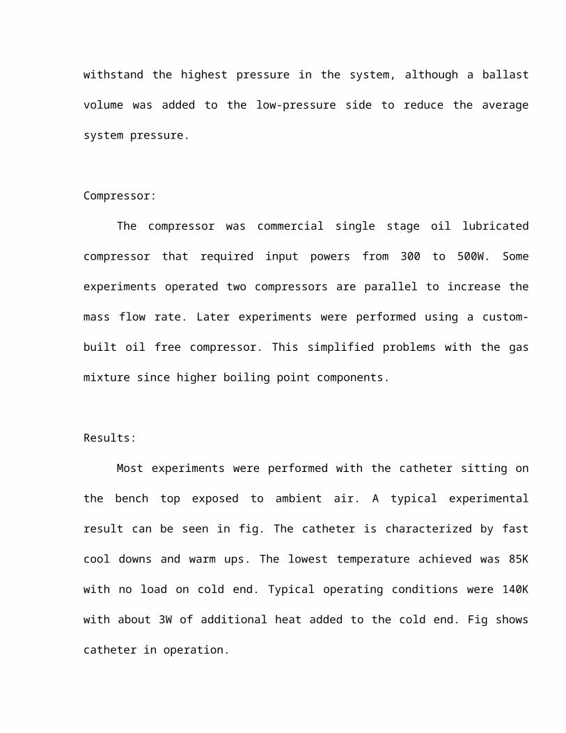
store 800KJ of energy. Kaolin and titanium dioxide are the white pigments used in paint
paper and plastics manufacturing. However as the ores contain magnetic contaminants
such as Hematite (Fe2O3) and Magnetite (Fe3O4), which discolor the pigments, turning
bright white into off-white. Kaolin mineral deposits also contain Ilmenite, a discoloring
compound of Titanium dioxide and Iron.
Most ore processing is done on site using either traditional copper or low temp
superconductivity magnetic separators. Low temperature superconductivity magnetic
separators shrink power consumption, but require liquid Helium, some thing that remote
suppliers can’t readily deliver and with which local operators have had little experience.
High temperature superconductivity or HTS can mirror the low power consumption of its
low temperature counterpart but does it at a higher operating temp 20K versus 4K the
boiling point of liquid Helium. Since Carnot efficiency dictates that the higher the
temperature the easier it is to remove the heat, a higher operating temperature translates
to a simpler lower cost refrigeration system. It is so simple that the equipment doesn’t ever
need liquid system.
PROCESSING OF ORE
The system processes one in batch made by pumping unprocessed clay slurry
through a non magnetic 3000 series stainless steel pipe; the pipe contains an in line
canister filled with a 400 serial "soft magnetic" stainless steel wool filter. Encircling the
canister is an 0.8m high temperature. Superconductivity solenoidal magnet wound from
silver sheathed Bismuth Strontium Calcium Copper Oxygen (Bi-2223) power-in- tube
multifilament tape.
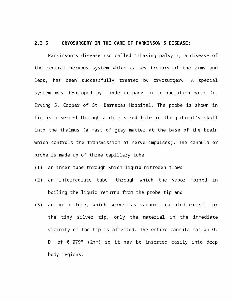
As the unprocessed slurry passes through the canister the magnetic field is cycled
on. When the magnet is energized the magnetic contaminants are attracted to and trapped
by the steel wool filter, while the nonmagnetic particles pass through the filter and are
collected as processed product. When the magnet is cycled of, the magnetic force drops,
releasing the contaminants, which are then flashed out with water.
The cycle repeats with a batch every 10 to 20 minutes depending on the processing
the volume and the magnetic fraction of the clay. Kaolin typically has magnetic fraction of
2 to 5%, while the titanium dioxide can measure as high as 50%. A typically filter will list
for approximately 8000 hrs at continuous operation.
Functionally the HTS system operates the same way also conventional copper or low
temperature superconductivity system, except that it was a high temperature magnet to
generate the magnetic field.
The separators high-temperature superconductive coil consists of a stacked double
pan cake structure in which the pan cakes are spliced together to for, a continuos
conductor. The assembly mounts inside the toroidal vacuum cryostat held inside an Iron
yoke.
The size was not chosen arbitrarily; it matches the processing volume of the
smallest commercial magnetic separator. Because processing volume is proportional to
the radius squared, a smaller magnet would reduce capacity significantly.
LOOKING AHEAD
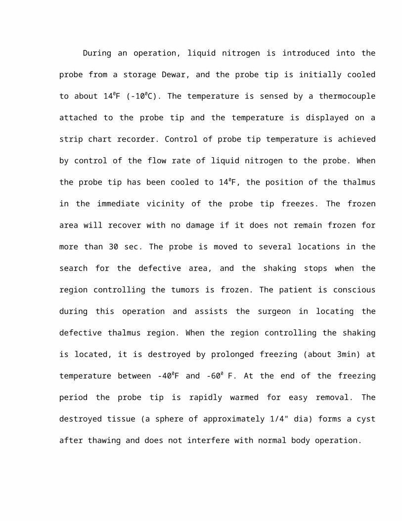
A successful HTS separator may have a potential future beyond Kaolin and titanium
oxide processing. There are other mineral applications worth investigating. In addition
some research work has been done in environmental remediation areas.
It has been experimentally verified in the lab that it is possible to remove Uranium oxide
compounds from contaminated soils and biological contaminants from waste water.
2.5.1 THE MEISSNER EFFECT AND FLUX PINING
In addition to zero resistance, the other important property of super conductor is the
Meissner effect, by which magnetic fields are driven out of super conductor. This property
can be used to levitate a magnet.
Even though Meissner discovered the expulsion of magnetic fields from super
conductors in 1933, it was not until 1987 with the advent of type II superconductors or
HTSCs that levitation effects could be studied in open air using LN2 induced
superconductivity at 77K.
When a magnet is placed near a superconductor and its magnetic field is excluded
from entering the superconductor, the distortion of field lines results in a force which can
lift the magnet against gravity, provided the magnetic forces are strong enough. At
equilibrium, the magnet "floats" a short distance from the superconductor.
The HTSC generally used in YBCO. The effect generally dies away once the HTSC
block warms to above the critical temperature.
Flux pinning magnetic place in TBCCO HTSCs. When magnetic flux lines become
pinned in the HTSC at 77K, the base can be rotated which leads to the magnets rotating
as well because the flux lines have to remain stationary.
The Meissner effect provides a force to lift a magnet above a superconductor, but
whenever a magnet is in motion, there is also a drag force. The combination of these two
affect the performance and design of any practical magnetic bearing surface.
2.5.2 MAGNETIC LEVITATION VEHICLES
The most well advertised possible application of superconductivity is that of maglev
trains, proposed to run at 500 km/hr. Present prototype technology can achieve speeds up
to 550 km/hr (Japanese MLX01, Dec-97).
Two different kinds of maglev are competing in today's prototype phase of
development, the difference being the way by which the vehicle attaches to the guide way.
i) Electromagnetic (or attractive) suspension:- it depends on the force of attraction
between the electromagnets and a steel guide. Because the force of attraction
decreases with increasing distance, this system is inherently unstable. The
prototype German Transrapid vehicle is proposed to carry 200 people at 500 km/hr
with levitation height of 8mm, the power consumption being 43 MW.
ii) Electro-dynamic (or repulsive) suspension:- It depends on the repulsive forces that
come in to play between moving magnets and eddy currents that they induce in a
conducting guide way. The repulsive force is inherently stable with distance and
comparatively large levitation heights can be achieved (8-10 cms). The null flux
arrangement on Japanese design tends to reduce the magnetic drag force and thus
the propulsion power needed.
Problems with HTSCs range from questionable mechanical strength to high AC
losses. HTSCs are well known for their brittleness & low fatigue strength. Repeated
stressing of the superconductor due to magnetic pulses leads to crack propogation and
early failure.
Also, AC variations in the magnetic fields of the permanent magnets leads to
dissipation of energy. These losses are quite significant in HTSCs like YBCO.
All in all, if maglev vehicles are to contribute significantly to future transport systems, the
drawbacks listed above need to be overcome & a way has to be found to reduce the initial
capital investment required for the system setup.
2.5.3 ZERO FRICTION SUPER CONDUCTING BEARINGS
A frictionless bearings is every mechanical designers dream, and a bearing in
which the two surfaces never make contact is close to that ideal. magnetic bearings
achieve mechanical separation & when other dissipative effects are minimized ,they can
be extremely good bearings, allowing rotational speeds not achieved by any other way.
Though conventional magnetic bearings have been widely used & have many
advantages, as compared to hydrodynamic or roller bearings, like low power dissipation &
higher speeds, they require mechanical support in at least one dimension or an active feed
back in the electromagnetic circuit.
The use of super conducting components in magnetic bearings offers the potentials
to eliminate the control system and further reduce power dissipation of the system. The
obvious disadvantage is that superconductors need a cryogenic refrigerant.
Conventional coil-magnet bearing system, used successfully for many years in the
ultrahigh speed rotor suspension now look set to be replaced by Passive Meissner effect
bearings using type II superconductors (HTSCs) which can be stable without a feed back
system and yet achieve speeds in excess of 100,000 rpm.
Magnetic stiffness is an important parameter for bearing design and is defined as
the restoring force due to flux pinning that acts on a rotor which drifts off-center. Efforts to
increase the stiffness require clever design and new materials. Superconducting magnets
generally require to be controlled in five direction, up, down, side to side, pitch and yaw.
Magnetic pressures of about 105 N/m2 have been achieved for superconducting
magnets which is comparable to that for conventional magnetic bearings.
a) Melt textured YBCO bearings
For bearings, the key factors are load capacity, stiffness and damping. The Allied
Signal co. has built a prototype device using melt texture YBCO which satisfies the
above factors even at speeds nearing to 500,000 rpm. Load capacities of 5-30 psi
have been achieved.
b) Hybrid superconductor magnet bearings (HSMBs)
The concept of hybrid bearings utilizing both superconductors and permanent
magnets uses the magnet to magnet repulsion to support the load and a
superconductor to stabilize the system. The magnetic system between two
permanent magnets is quite unstable and the superconductor, with its good
diamagnetic properties acts as a stabilizing agent.
HSMBs can be built in various combinations like thrust, radial or thrust-radial.
The trade off in HSMB design is between the cost of refrigeration and the
benefit of lower frictional losses in the bearings. Generally, HSMBs require only 20
mW of dissipitive cooling as compared to 20 W needed for bearings presently used
by NASSA for space application. Because refrigeration is free of charge in outer
space, HSMBs are sure to find a place in future space programs.
c) Superconducting bearings for space telescope applications
The HSMBs system for a lunar telescope is based on passive magnetic levitation
and the flux pinning effect of HTSCs. The unique ability of HTSCs to adopt to low
temperature and vacuum environments of space or on the moon and their ability to
enhance system stability passively without power consumption make them ideally
suited for space application.
Diamagnetism is the property that makes superconductors shield their
interiors from an applied magnetic field. However, in HTSCs, any magnetic field
already present would remain trapped inside the superconductor. For HTSCs, the
superconducting state exists below 90K. importantly, the temperature of the lunar
surface away from the sun can reach as low as 30K-60K.
The use of HSMBs circumvents problems related to use of conventional
lubricants in cryogenic and vacuum environments such as freeze and evaporation.
It also allows use of less tight tolerance in its manufacturing and assembly as
compared to conventional mechanical bearings. Clogging problems due to lunar
dust are also eliminated in HSMBs. Thus a superconducting bearings is an
attractive replacement for conventional bearing in the cold and dusty lunar
environment for an extended period of time.
For the equatorial mount of the telescope, a superconducting bearing and
driving mechanism capable of tracking stars to a precision of better than 0.25 arc
seconds rotates the platforms at a constant velocity 23 m RPM.
d) Fly wheel energy storage using HTSCs
A promising future application of HTSC bearings is in energy storage via fly wheels.
The entire apparatus is housed in a vacuum chamber to eliminate losses due to air
drag. Only the HTSC bearing need be cooled to LN2 temperature: that bearing acts
on a permanent magnet attached to the fly wheel, both to suspend it and keep it
stable.
Energy is transferred into and out of the flywheel as follows-
Current flows through a coil adjacent to the fly wheel magnet, repelling it and
causing the fly wheel to spin, proper synchronization of current and magnet velocity
being maintained to accelerate the fly wheel. The current is switched off once the
flywheel reaches top speed, losing almost no energy to friction or air drag because
of the vacuum. Later, when the circuit is reconnected the magnet spinning on the
flywheel generates electricity in the coil which can be used later to run an external
load.
For electric utilities wishing to store power for 12 hours, flywheels becomes
competitive only when the energy loss in the bearing is very low so that the fly
wheel would loose energy of the order of 1% in 10 hrs, or have a slow down rate of
10-5 to 10-4 Hz/sec. Lab models have achieved slow down rates of below 10-4
Hz/sec.
2.5.4 SUPERCONDUCTING MAGNETIC ENERGY STORAGE (SMES)
SMES stores electricity for long periods of time in superconducting coils. This
systems will be used by electric power companies of the future to reduce power
interruptions, which currently account for losses of over 15 billion dollars/year in the US.
With the advent HTSC SMES, the whole concept of SMES changed from being a design
dream to a costly but attainable working prototypes.
SMES systems, designed to provide power for relatively short periods of time, are
characterised by high efficiency and rapid response. A SMS is characterised by both its
power rating and storage capacity. In a study conducted by the US Department Of Energy,
a storage range of 2-200 MWh at power levels of 4-4MW were considered suitable for
commercialization. The unit geometry could be of either toroidal of solenoidal type and
either of two kinds of conductors (BSCCO or YBCO) can be used. While making an
investment decision about building an SMES, future managers would have to strike a
trade of between refrigeration cost (and reliability), structural strength, ground trip
efficiency and so on.
As of now, the toroidal configuration has look most promising due to its technical
superiority and the fact that it has a low external magnetic field which is advantageous in
locating the unit near a utility or customer load.
SMES Refrigeration system
For an SMES system, though the coil resistance in the superconducting state is
negligible, the refrigerator requires electric power which must be accounted for during
efficiency evaluation.
The heat loads that must be removed by the cooling system include conduction
through the support system, radiation from warmer to colder surfaces, AC losses in the
conductor and connections from the cold to warm power leads.
All in all, the SMES system has shown great promise in the design stage and it is
hope that proper commercialization of this vital technology would lead to significant
savings in the potentially important electric utility supply system.
2.6 CRYOMANUFACTURING
2.6.1 INTRODUCTION
Cryogenic technology finds ever growing applications in the manufacturing industry,
ranging from steel making, grinding to fabrication of complex structures used in space
technology. Cryogenic technology improves the product quality after machining, minimizes
or completely eliminates faults in assembly during manufacturing.
The ultimate stress, Young's module and the yield stress of most engineering
materials increase with cooling to Cryogenic temperature. It has been established that the
chip tool interface temperature and cutting forces reduce while the chip ratio increases
when cutting is done using a single point tool at Cryogenic temperature.
Materials like plastic and rubber brittle at low temperature and thus become easy to
grind and crush using Cryogenic technology.
Some of the widely used Cryogenic manufacturing processes are discussed below.
2.6.2 LN2 CRYOGEN AS A CUTTING FLUID FOR PRECISION GRINDING
Grinding of steel requires high specific energy at high speed. This results in very
high temperature which reduce the dimensional accuracy and wheel life due to plastic
deformation and rapid wear of cutting points respectively. This induces large tensile
residual stresses, microcracks and structural changes in the ground components.
Cryogenic cooling by agents like LN2 reduces the above problem to a great extent.
Cryogenic manufacturing has resulted in relatively lower cutting forces, longer tool life and
better cutting surfaces.
The setup for cryogrinding is shown in the figure. The LN2 comes in from its
reservoir under air pressure and impinges on to the grinding zone from suitable distance
and angle. The flow of LN2 is controlled using a number of valves. The cooling to cryo
temperatures leads to lower grinding interface temperatures which prevents plastic flow of
material & hence smoother surfaces that are free of surface damage. as can be seen from
the microphotos, cryogrinding leads to a definite improvement over conventional grinding.
2.6.3 CRYOGRINDING OF RUBBER
Scrap or waste rubber can be ground and recycled so that the requirement of fresh
rubber is minimized. use of this recycled rubber reduces the mould wear & lessens the
total energy requirements.
As compared to conventional grinding, grinding at cryo temperatures has definite
advantages because rubber becomes extremely brittle at the low temperatures.
Design and construction of the grinding machine
The fundamental principle of the process is that the scrap rubber is cooled to below
its embrittlement temperature & then pulverized in a hammer mill. The schematic of the
process is as shown in the figure. Pre-sized rubber is fed into the hopper & conveyed to
the hammer mill by means of a screw conveyor. LN2 is sprayed directly onto the rubber
when it passes from the hopper to the hammer mill.
The 3 main components of the machine are the screw conveyor, the hammer mill &
the LN2 injection system.
The carbon black filled rubber takes about 10 minutes to attain about -100 degree
C when submerged in the LN2 spray. Large scale systems marketed by an American
company has a production rate of about 1 to 3 tons/hr. The systems are based on a capital
investment of about $40,000 & an LN2 consumption rate of 2.64kg/kg of product for a
reduction rate of 150kg/hr.
2.6.4 CRYOGENIC SHRINK FITTING
For the assembly of components such as shafts in the wheels and rotors, of liners
in cylinders & of bushes & bearings in housings, it is necessary to bring dimensional
changes in both or one of the mating parts, either by heating the female (hub) or by
cooling the male part (shaft).the latter method is called the "expansion fit method" & has
inherent advantages over the conventional "contraction fit" technique. To achieve a
reasonable reduction in the diameter, the shaft must be cooled to a temperature of about
730 K, which is achievable using LN2.
The advantages of the cryo fitting technique are as listed below-
1. The technique is quick & requires minimal special equipment.
2. Mechanical damage & metallurgical changes in the materials are absent.
3. Holding ability of cryogenically shrink fitted joint is considerably greater than
that for other methods.
Cryogenic shrink fitting is being widely used for making interference fits. When the
two members are assembled & the temperature returns to the normal, a radial pressure
sets up at the interface causing the two parts to be held firmly.
Main applications of cryogenic Shrink fitting are in assembly of rims over locomotive
engine wheels, assembly of kiln support rollers.
2.6.5 FABRICATION OF PRESSURE VESSELS
Here, the die for manufacture of pressure vessels is cooled to LN2 temperatures.
The vessel to be formed is kept in the die. The pressurized Nitrogen gas is admitted in to
the vessel until the container stretches by about 15% and then the vessel is removed from
the die and allowed to warm upto room temperature.
2.6.6 ADVANTAGES OF CRYOMANUFACTURING
The following advantages of cryomanufacturing over conventional methods are most
evident:
1. Cryogrinding provides better surface integrity & finish when compared to
conventional grinding by reducing the surface tensile residual stresses to
about 20% of their original values, at the same time improving tool life to a
great extent.
2. The brittle nature of rubber at cryo temperatures facilitates easy crushing &
grinding with reduced energy requirements.
3. Cryo shrink fitting provides greater holding forces, while at the same time
preventing any mechanical or metallurgical damage to the specimen.
4. Fabrication of large pressure vessels having complex shapes is facilitated by
use of nitrogen induced stretching in the moulds.
2.7 CRYOPRESERVATION
2.7.1 INTRODUCTION
The preservation of perishable commodities particularly food stuffs, fruits and
flowers, etc is more important now and then ever before in history. Today’s large urban
population requires tremendous quantities of food, naturally these foodstuffs must be kept
in preserved condition until they are finally consumed. Also, many products particularly
fruits, flowers and vegetables are produced during certain seasons of the year, they must
be stored and preserved if they are to be made available through the year.
Conventionally, drying, prickling and salting methods were used and still are used
where no other means are available. However these methods are inadequate for certain
products. The disadvantages associated with conventional one are:
1) The characteristics of fresh food and fruits such as appearance, vitamin content,
taste are changed.
2) These methods lead to quality deterioration e.g. discoloration, loss of vitamins,
disintegration of product because of physiochemical changes.
3) Quality of perfumes gets deteriorated in case of flowers.
Refrigeration is one of the important method for preservation of food. Food
preservation at low temperature retains the quality of food. Cryopreservation is recent
development in refrigeration technology.
During the last decade considerable progress has been made in agriculture
biotechnology, and complete plants have been regenerated from cell, and organ cultures
of a number of crop species cryopreserved in liquid Nitrogen for various lengths of time.
2.7.2 LIQUID NITROGEN SYSTEM FOR FOOD TRANSPORTATION.
For food preservation during transportation through trucks, the liquid Nitrogen
system is shown in fig.(2.7.1). The liquid Nitrogen containers are located behind the
driver’s seat in the cabin. The temperature of the space inside the truck was registered by
the vapor pressure thermometer with its sensing element located inside the space and
dials located in the driver’s cabin. The liquid delivery system comprised of adapters fitted
over the containers. These adapters serve as convenient means for providing an air -tight
lid over the containers and liquid Nitrogen out of them.
Compressed air available in the truck for operating its air brake system is to be
used for providing the higher pressure required for pumping the liquid Nitrogen from the
containers.
The pressure of air acting over the surface of the liquid Nitrogen in the container is
to be regulated by operating a solenoid valve and relief valve.
An operator travels in the driver’s cabin for operating the solenoid valve and
admitting compressed air as and when desired. When the truck temperature rises by 2 C,
the operator closes the air relief valve and opens the solenoid valve causing the
compressed air to flow into the container and pump liquid Nitrogen into the truck. Due to
the spray of the liquid Nitrogen, the truck temperature decreases and whenever it reaches
–17 C, he closes the solenoid valve and opens the pressure relief valve causing the flow
of liquid Nitrogen to stop. It has been found that the spray is to be maintained for the
duration of 10 minutes at interval of 30 minutes.
This system has a number of advantages:
1) Liquid Nitrogen system is quite economical.
2) The high quality of frozen product can be maintained using this system.
3) With this system it is possible to extend the area of marketing to over the
long distance.
4) Rate of spoilage is as low as 10% compared to 40% with refrigerated
system.
2.7.3 CRYOGEN FREEZING & STORAGE OF FISH &SHELLFISH
For the last two or three decades, the cryogenic freezing is replacing the traditional
freezing system in western countries. Cryogenic freezing using cryogen (such as liquid
Nitrogen) bears the advantages of quick freezing.
The process of freezing may be divided into three phases:
1) Pre-cooling: -The product is brought down to its freezing point.
2) Freezing: -Maintains a constant temperature and phase change occurs due to
formation of ice crystals.
3) Tempering - Temperature of center falls gradually towards the temperature of
freezing medium.
The initial investment is low for liquid Nitrogen freezing.
2.7.4 CRYOPRESERVATION OF PLANTLETS & LIVING CELLS
It is possible to store plantlets and microbes in cryogen to maintain genetic stability
and viability. Liquid Nitrogen provides a storage temperature of –196 C and storage
equipments and containers are commercially available.
Cells undergo severe temperature changes during freezing. For successful
cryopreservation requires certain procedure:-
1) Low cooling rate down to –30 C.
2) Fast cooling rate below –30 C.
3) Fast warming rate during thawing.
4) Minimum concentration of electrolytes in the freezing suspension.
5) Addition of cryoprotectants to the freezing suspension to protect living
cells against freeze –thaw injury.
Cryopreservation is used in genetic engineering for preserving cell culture of
different plants to be cloned. Cryopreserving large plantlets though difficult, attempts with
young seedlings of pea and carrot have shown encouraging results. Cryopreservation
offers following advantages:-
1) They are easy to culture and regenerate into plants.
2) They yield pathogen-free stocks for propagation.
3) Being genetically more stable they ensure stability of clones.
4) Ideal material for the international exchange of germplasm.
2.7.5 CONCLUSION
Liquid Nitrogen is most preferred cryogenic liquid for food storage because it is
safe, nontoxic, chemically inactive and commercially available. Cryopreservation retains
the quality and natural freshness of food, fruits and flowers.
During cryopreservation of plantlets and living cells care must be taken to avoid
accidents. Proper ventilation must be assured. There is a possibility of splashes and
explosion of glass containers on thawing. Otherwise liquid Nitrogen is best cryogen for
cryopreservation.
SQUIDS (Superconducting Quantum Interface Devices)
A squid consists of a loop with two JJ interrupting the loop .it is extremely sensitive
to the total amount of magnetic field that penetrates the area of the loop - the voltage
measured across the device is a strong indicator of the field around the loop.
SQUIDs are made use of in instruments designed for detecting very low magnetic fields.
Currently, fields less than 10billonth of that of the earth can be detected using such
instrument.
SQUIDs can be used for high resolution magnetometers, motion detectors, sensitive
voltmeters, picoammeters and other detectors all used for wide variety of applications like
neuromagnetology, gravity measurement, high speed scanning and non destructive
evaluation (NDE) of stressed machine components.


![Section -I: Introduction - Shodhgangashodhganga.inflibnet.ac.in/bitstream/10603/3032/7/07_chapter 1.pdf · Section-I: Introduction 6 CIBA [29] described wool-reactive dyes containing](https://img.pdfslide.us/doc/110x75/5ebf79e47d2182694f69b664/section-i-introduction-1pdf-section-i-introduction-6-ciba-29-described.jpg)