Embed Size (px)
Citation preview
SECTION DESECTION DE
Génie mécanique
Calculation of Rigin a 2.5-axis H
Motivation & ObjectivesHigh-speed machining (HSM) is characterized by high dynamic demands due to frequent and high velocity
changes and high instantaneous power consumption.Existing models of machine tool rigid body dynamics are mostly restricted to kinematics, without taking into
account the realistic feed velocity profiles. The tool engagement conditions are not included and there’s nointeraction with the tool path. A comprehensive model of MT rigid body dynamics in a HSM process still doesp p g y y pnot exist. Control-related constraints, as well as many electromechanical constraints of MT drives, have notbeen modeled in the existed models.
The objective of this thesis was to develop a software which can simulate a 2½D milling process byperforming the following tasks: parameterization of the tool path geometry and determination of cuttingengagement angles, generation of jerk-limited feed profiles on tool path segments, calculation of cutting, inertialand frictional forces and torques, calculation of power and energy consumed in the machining process andvisualization of effects of kinematic parameters on it. This software should serve as a part of an overall solutionfor the problem of MT rigid body dynamics modeling.
Main Program & S1. Engagement angleThe pixel-based parameterization of the tool path and the
determination of cutting engagement angles has been doneby use of an external software programmed by Mr. NicolasPlanquet in his MSc thesis. All necessary modifications ofthis program have been made to incorporate it as a modulein our program. This module provides the values of cuttingengagement angles during the whole machining processand parameterized tool path coordinates as well.
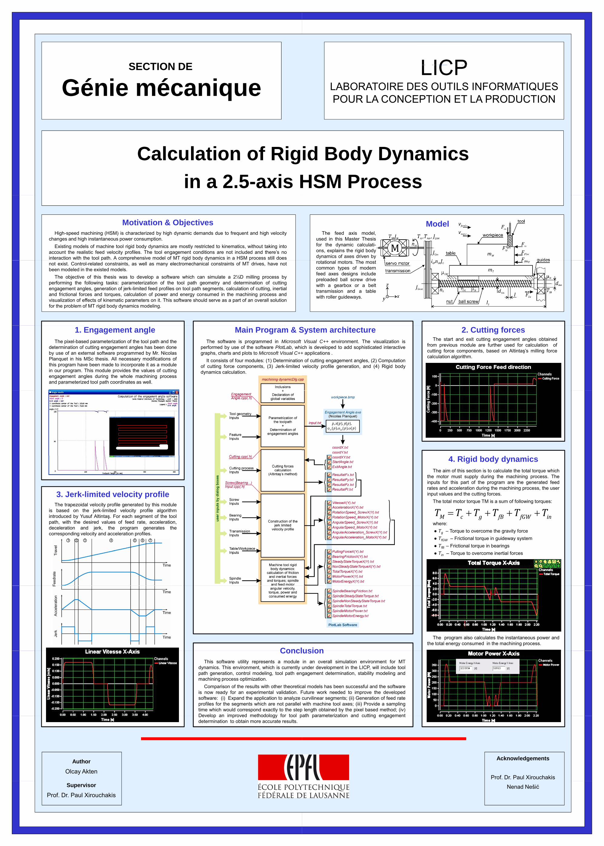
The software is programmed in Microsoftperformed by use of the software PlotLab, whigraphs, charts and plots to Microsoft Visual C++
It consists of four modules: (1) Determinationof cutting force components, (3) Jerk-limiteddynamics calculation.
3. Jerk-limited velocity profileThe trapezoidal velocity profile generated by this module
is based on the jerk-limited velocity profile algorithmintroduced by Yusuf Altintaş. For each segment of the tool
th ith th d i d l f f d t l tipath, with the desired values of feed rate, acceleration,deceleration and jerk, the program generates thecorresponding velocity and acceleration profiles.
ConclConclThis software utility represents a module
dynamics. This environment, which is currentlypath generation, control modeling, tool path enmachining process optimization.
Comparison of the results with other theoreticis now ready for an experimental validation. Fsoftware: (i) Expand the application to analyzeprofiles for the segments which are not paralleltime which would correspond exactly to the stepDevelop an improved methodology for tool p
Author
Olcay Akten
Develop an improved methodology for tool pdetermination to obtain more accurate results.
Supervisor
Prof. Dr. Paul Xirouchakis
LICPLaboratoire de Conception de Systèmes Mécaniques
LICPLABORATOIRE DES OUTILS INFORMATIQUES POUR LA CONCEPTION ET LA PRODUCTION
id Body Dynamics HSM Process
The feed axis model,used in this Master Thesisfor the dynamic calculati-ons, explains the rigid bodydynamics of axes driven by
i l Th
Model
rotational motors. The mostcommon types of modernfeed axes designs includepreloaded ball screw drivewith a gearbox or a belttransmission and a tablewith roller guideways.
System architecture 2. Cutting forcesThe start and exit cutting engagement angles obtained
from previous module are further used for calculation ofcutting force components, based on Altintaş’s milling forcecalculation algorithm.
Visual C++ environment. The visualization isch is developed to add sophisticated interactive
+ applications .n of cutting engagement angles, (2) Computationvelocity profile generation, and (4) Rigid body
The aim of this section is to calculate the total torque whichthe motor must supply during the machining process. Theinputs for this part of the program are the generated feedrates and acceleration during the machining process, the userinput values and the cutting forces.
The total motor torque TM is a sum of following torques:
4. Rigid body dynamics
M c g fB fGW inT T T T T T= + + + +where:● Tg – Torque to overcome the gravity force● TfGW – Frictional torque in guideway system● TfB – Frictional torque in bearings● Tin – Torque to overcome inertial forces
usion
The program also calculates the instantaneous power andthe total energy consumed in the machining process.
usionin an overall simulation environment for MTunder development in the LICP, will include toolgagement determination, stability modeling and
al models has been successful and the softwareFuture work needed to improve the developedcurvilinear segments; (ii) Generation of feed ratewith machine tool axes; (iii) Provide a sampling
p length obtained by the pixel based method; (iv)path parameterization and cutting engagement
Acknowledgements
Prof. Dr. Paul Xirouchakis
path parameterization and cutting engagement
Nenad Nešić


![Flambage plastique des coques de révolution sous pression ...€¦ · Flambage plastique des coques de révolution sous pression interne. Génie mécanique [physics.class-ph]. Université](https://img.pdfslide.us/doc/110x75/61210baa9caefb4f1637c2b7/flambage-plastique-des-coques-de-rvolution-sous-pression-flambage-plastique.jpg)