Embed Size (px)
Citation preview

----------------------------------------------------------------------------------------Section Updated: 10/25/2007 11:05 AM at http://www.lotus-europa.com ----------------------------------------------------------------------------------------
SECTION J
BRAKING SYSTEM
Section Description Page
J.1 GENERAL DESCRIPTION 7
J.2 BLEEDING THE SYSTEM 8
J.3 PAD REPLACEMENT 9
J. 4 SHOE REPLACEMENT 9
J.5 FRONT CALIPER 12
J.6 REAR DRUMS 12
J.7 CALIPER OVERHAUL 12
J.8 DRUM OVERHAUL 14
J.9 FRONT CALIPER MOUNTING PLATE/DUST SHIELD 14
J.l0 FRONT BRAKE DISC 15
J.11 PEDAL ASSEMBLY 15
J.12 MASTER CYLINDER 16
J.13 MULTI-BRANCH UNIONS 18
J.14 SERVO UNIT 19
J.15 HANDBRAKE 20
J.16 FAULT FINDING 20
ADDITIONAL INFORMATION
J.17 SOVY DEVICE ADAPTOR 22

PAGE 2 SECTION J – BRAKING SYSTEM
----------------------------------------------------------------------------------------Section Updated: 10/25/2007 11:05 AM at http://www.lotus-europa.com ----------------------------------------------------------------------------------------
ILLUSTRATIONS
Fig. No. Description Page No.
1 Components of the Braking System, Series I VehiclesSeries I Vehicles (L.H.D.) 3
2 Components of the Braking System,Series II Vehicles (R.H.D.) 4
3 Components of the Braking System,Series II Vehicles (Federal, L.H.D.) 5
4 Components of the Braking System,Series II Vehicles with Servo (R.H.D.) 6
5 Rear Brake Adjustment 7
6 Front Brake Caliper 9
7 Handbrake Adjustment 10
8 Components of the Front Caliper 11
9 Components of the Rear Drum Brake 13
10 Components of the Pedal Assembly 16
11 Components of the Master Cylinder 17
12 Dismantling the Master Cylinder Piston Assembly 17
13 Brake Master Cylinder and Fluid Reservoir 18
14 Servo Unit 19

SECTION J – BRAKING SYSTEM PAGE 3
----------------------------------------------------------------------------------------Section Updated: 10/25/2007 11:05 AM at http://www.lotus-europa.com ----------------------------------------------------------------------------------------

PAGE 4 SECTION J – BRAKING SYSTEM
----------------------------------------------------------------------------------------Section Updated: 10/25/2007 11:05 AM at http://www.lotus-europa.com ----------------------------------------------------------------------------------------

SECTION J – BRAKING SYSTEM PAGE 5
----------------------------------------------------------------------------------------Section Updated: 10/25/2007 11:05 AM at http://www.lotus-europa.com ----------------------------------------------------------------------------------------

PAGE 6 SECTION J – BRAKING SYSTEM
----------------------------------------------------------------------------------------Section Updated: 10/25/2007 11:05 AM at http://www.lotus-europa.com ----------------------------------------------------------------------------------------

SECTION J – BRAKING SYSTEM PAGE 7
----------------------------------------------------------------------------------------Section Updated: 10/25/2007 11:05 AM at http://www.lotus-europa.com ----------------------------------------------------------------------------------------
J.1 - GENERAL DESCRIPTION.
Hydraulically operated brakes, discs on the front and drums on the rear are fitted to all four wheels.They are operated by means of a floor-mounted pedal situated in the drivers foot-well.The hydraulic system may be dual line (Federal) or conventional single line.The dual line system provides separate hydraulic circuits for the front and rear brakes: should one circuitfail the other circuit is unaffected and the car can still be stopped. Incorporated in the Federal brakingsystem are a pressure differential warning valve and a 'brake fail' warning lamp with test switch.The lamp will glow RED if a failure occurs anywhere within the braking system, or if the test switch isoperated.The front brakes are of the trailing caliper type to minimize water entry, whilst the rear brakes are of thesingle leading shoe design.An 'umbrella' type handbrake is situated under the lower edge of the facia panel to the left (L.H.D) orright (R.H.D) of the steering column, and applies the rear brakes via a cable linkage.A vacuum operated servo is offered as optional equipment on vehicles with single circuit brakingsystems, and on Federal Specification vehicles as well. [1] When the engine is running, vacuum issupplied to the servo unit via a non-return valve, and both sides of the diaphragm are subjected to equalvacuum. Initial movement of the brake pedal admits atmospheric pressure to the rear face of thediaphragm resulting in a pressure difference, which causes the diaphragm to move forwards, thus brakepedal effort is considerably reduced.
Maintenance.The master cylinder reservoir is located on the front bulkhead, and is reached by opening the frontluggage compartment cover.Check the fluid level at intervals of 5,000 km. (3,000 miles), topping up if necessary to within 12 mm(0.5 in) of the top, using only the specified fluid (see section O).
Brake adjustments.When properly adjusted there should be 6 mm(0.25") free movement of the brake pedal beforethe piston in the master cylinder begins to move.When checking this setting, take care that thecarpets are not fouling the pedal.No manual adjustment to compensate for frontpad wear is provided or indeed necessary, asadjustment is automatic, but the rear drums areprovided with adjusting screws to ensure thecorrect relationship of shoes to drum.
Brake Pads and Shoes.Pads and shoes should be examined at regularintervals.Always use genuine replacement parts. It shouldbe understood that a metallic hiss is apparent with disc brakes. This is normal and should not beconsidered as a fault. If a metallic squeal is heard this is general indication of brake pads OVERDUE forreplacement. Under no circumstances allow the pads to wear below 1.6 mm (1/16") thickness, or theshoes to wear to the level of the rivet heads.

PAGE 8 SECTION J – BRAKING SYSTEM
----------------------------------------------------------------------------------------Section Updated: 10/25/2007 11:05 AM at http://www.lotus-europa.com ----------------------------------------------------------------------------------------
Servo Unit Air Filter.The filter element should be replaced every 10,000 km. (6,000 miles).
Hydraulic Pipes and Connections.It is of vital importance that there are no leaks in the hydraulic system. Therefore, it is essential thatthese should be checked periodically, when the brakes are receiving normal maintenance inspection.All bundy pipes should be inspected throughout their entire length at intervals NOT EXCEEDING 6months, i.e. before and after the winter months.This is particularly important when salt and grit (which are both corrosive) are used in the clearance ofsnow or ice.
Brake Seals, Hoses and Fluid.The brake manufacturers recommend that at intervals NOT EXCEEDING 65,000 km (40,000 miles) or3 years, which ever is reached first, that the braking system be completely overhauled and all washers,seals and hoses renewed. Hydraulic servo units should be stripped, all old seals discarded, componentparts cleaned and examined and if in good condition, the unit rebuilt with the appropriate service kit. Allfluid should be drained, the system flushed with a correct cleaning fluid, then refilled with new fluid atintervals of 18 months.
J.2 - BLEEDING THE SYSTEM.'Bleeding' is the process of removing air from the pipe line and cylinders and is necessary whenever anypart of the system has been disconnected, or the level of fluid in the master cylinder reservoir has beenallowed to fall so low that air has been drawn into the cylinder.When seals are worn it is possible for air to enter the caliper cylinders without any sign of leaking fluid,and cause a 'spongy' pedal action, which is the usual indication of bubbles of air in the system.The equipment that is necessary is a supply of brake fluid, a rubber bleed tube and a 7/16 A.F spanner.A small spanner should be used to avoid overtightening of the bleed screws.Fill up the reservoir with the approved fluid direct from the can and maintain the level throughout theoperation.Bleeding should start at the rear left-hand wheel.Push the rubber tube over the nipple and immerse the other end in a glass or transparent plastic containerholding sufficient fluid to cover the end of the tube. Unscrew the bleed nipple enough to allow fluid tobe pushed out (about half a turn) and proceed to pump fluid through by depressing the brake pedal untilno more bubbles appear. Close the nipple on a downward stroke of the pedal. Repeat this operation foreach nipple in turn from the farthest to the nearest to the master cylinder.The pedal should be operated by a succession of rapid long and short strokes. The pedal is pushed downthrough its full stroke, followed by two or three short rapid strokes, and then allowed to fly back to thestop with the foot right off.It is not necessary to stamp hard on the pedal but a quick, full stroke is required. If the floor matobstructs the full stroke of the pedal it should be removed.After all four wheels have been bled check the pedal stroke.If there is a springy feeling to the pedal bleed again at each nipple to confirm that the system is air-free.A slight variation of the routine is required if the system has been drained. The first time (to fill thesystem) each bleed screw is closed as soon as fluid is discharged regardless of the small bubbles thatmay be present and the second time round only a few strokes at each bleed screw are needed to finallydischarge the air.

SECTION J – BRAKING SYSTEM PAGE 9
----------------------------------------------------------------------------------------Section Updated: 10/25/2007 11:05 AM at http://www.lotus-europa.com ----------------------------------------------------------------------------------------
Springiness of the brake pedal can have other causes than air in the system.Flexing of the pedal lever, of the pedal mounting or of the master cylinder mounting is possible and canbe seen. Other possibilities not so readily visible are badly fitted, warped or otherwise distorted brakepads or shoes.
Tandem Master Cylinder.Bleed the rear brakes first, commencing with the left-hand wheel, then bleed the front brakes, similarlycommencing with the left-hand wheel.Use only a light pedal action and DO NOT push the pedal through at the end of its stroke. DO NOT 'try'the pedal until the system is fully bled, as either action will cause the plunger to move and actuate the'brake fail' warning lamp.If during the bleeding procedure the 'brake fail' lamp is actuated, the bleed nipple must be closed and anipple at the opposite end of the car opened.A steady pressure must then be applied to the pedal until the lamp goes out, when the pressure must bereleased immediately, and the bleed nipple closed, otherwise the piston will move too far in the oppositedirection and require resetting again. When the lamp goes out a 'click' will be felt on the pedal as thepiston moves back.
J.3 - PAD REPLACEMENT.1. Jack up the front of the car and remove the
road wheels.2. Remove any accumulated road filth from
around the brake pads in the calipers.3. Pull out the pad retaining pin clips,
withdraw the retaining pins and removethe brake pads and shims.
4. To enable new pads to be fitted push thepistons into their bores. This action willcause fluid to be returned to the mastercylinder, which, if it has recently beentopped up, may overflow. To avoid this,examine the fluid level and, if necessary,remove a quantity of fluid.
5. Fit new brake pads and shims, ensuringthat both are correctly fitted and that thepads are of the correct type. The shimsfitted incorporate an arrow, which must point in the direction of forward rotation of the wheel.
6. Refit the retaining pins and secure with the retaining pin clips.7. Operate the brake pedal several times to bring the pads into their working positions. Check that the
pads are free to move slightly; this indicates that the retaining pins are not fouling the pads.8. Replace the front wheels.
J.4 - SHOE REPLACEMENT.
1. Jack up the rear of the car and remove the road wheels.2. Ensure that the handbrake is released. In some cases it may be found necessary to slacken off the
shoe adjusting screws to eliminate all resistance. If, having done this, difficulty is still experienced inremoving the drum, a few taps with a raw-hide or plastic-faced mallet should help.

PAGE 10 SECTION J – BRAKING SYSTEM
----------------------------------------------------------------------------------------Section Updated: 10/25/2007 11:05 AM at http://www.lotus-europa.com ----------------------------------------------------------------------------------------
3. Having noted the positions of the shoes and which perforations are used to locate the retractingsprings, remove the shoe holding down springs by turning the top washer through 90° and pullingoff the washer and spring.
4. Disengage each shoe from its location slot in the wheel cylinder and the fixed pivot and remove theshoes. Remove the retracting springs.
5. Re-assemble the retracting springs between two new shoes of the correct type, ensuring that thesprings are in the correct relation to the hub and that the shoes are in the right attitude.
6. Lightly smear brake grease on all pivot points and the brake-shoe support pads.7. Snap the shoes into position, ensuring that the handbrake link is correctly positioned.8. Replace the shoe holding down springs and retain them by turning the top washers through 90°.9. Replace the brake drums and screw in the brake adjusting screws until the drum is locked, then
slacken until a running tolerance is attained.10. Replace the drum retaining screws, the road wheels and wheel nuts and lower the car. Fully tighten
the wheel nuts and replace the hub cap.
NOTE: The new shoes should 'bed in' fairly quickly until they take on the general contours of the drums,and lose their rough surface.The rear brakes will, therefore, need to be re-adjusted fairly soon after replacing the shoes.
Handbrake.The handbrake consists of a combined cable and mechanical linkage system operated by an 'umbrella'type control situated under the facia panel and operating on the rear brakes drums. Very littlemaintenance is required apart from occasional greasing of pivot points and lubricating of the cables.The handbrake also gives indication of need to adjust the rear brakes, apart from excessive travel of thebrake pedal. It will be noticed that the ratchet will have to be extended much further to ensure safeparking.Excessive movement of the handbrake control will automatically be eliminated with adjustment of therear brake shoes. In the unlikely event of it not doing so, due to gradual stretching of the cables, there isa further adjustment situated inside the central chassis backbone.
To reach it, pull up the central armrest (clippedfront and rear).Take out the foam plastic dust seal and so revealthe oval access hole. The handbrake adjustmentwill be visible underneath the front gear changeshaft. With the rear brakes correctly adjusted,slacken off the locknut on the cable connectionand take up the slack with the second nut untilthe handbrake is fully effective when pulled outabout 40 mm (1.5 in.)Check that when the handbrake 'umbrella' isfully released it completely frees the brakeshoesTighten the locknut. Replace the dust seal andarmrest.

SECTION J – BRAKING SYSTEM PAGE 11
----------------------------------------------------------------------------------------Section Updated: 10/25/2007 11:05 AM at http://www.lotus-europa.com ----------------------------------------------------------------------------------------

PAGE 12 SECTION J – BRAKING SYSTEM
----------------------------------------------------------------------------------------Section Updated: 10/25/2007 11:05 AM at http://www.lotus-europa.com ----------------------------------------------------------------------------------------
J.5 - FRONT CALIPER
To remove:1. Raise the front of the car and remove the road wheel.2. Remove the brake pads (section J.3). If it is intended to overhaul the caliper assembly, depress the
brake pedal to bring the pistons into contact with the discs, thus facilitating the removal of thepistons.
3. Remove the flexible hose from the caliper and plug or clamp the hose to avoid unnecessary leakageof brake fluid or the possible ingress of foreign matter.
4. From the inner face of the caliper unscrew the two mounting bolts and remove the caliper.
To replace:1. Replace the caliper and secure it with the two bolts, tightened to the torque setting given in the
Technical Data Section.2. Unplug (or unclamp) the flexible hose and connect the hose to the caliper.3. Push the pistons into their bores sufficient to allow replacement of the brake pads and shims.4. Replace the front wheel.5. Bleed the braking system (section J.2). It should be necessary to bleed only that brake which has
been removed and replaced. However, in the case of air having infiltrated the system, section J.2 willhave to be followed in its entirety.
J.6 - REAR DRUMS.
To remove:1. Remove the wheel trim and bend up the lock tab on the hub nut. Slacken the hub nut.2. Raise the rear of the car and remove the road wheel.3. Remove the brake drum and shoes (see section J.4).4. Remove the split pin and clevis pin attaching the handbrake cable clevis to the handbrake link.5. Detach the bundy tubing from the wheel cylinder and plug the end of the tube to prevent
unnecessary loss of fluid and the possible ingress of foreign matter.6. Remove the hub retaining nut and using an extractor pull off the hub.7. Undo the four backplate retaining bolts and remove the backplate.
To replace.Replacement is a reversal of the procedure outlined above. For torque settings see Technical DataSection. Bleed the system (see Section J.3).
J.7 - CALIPER OVERHAUL.
To remove.Remove the caliper (see section J.5).
To dismantle.1. Remove the outer sealing ring securing the dust cover and pull off the cover.2. Remove the piston and extract the inner sealing ring.
Inspection and Cleaning.1. Wash the pistons and piston bores in commercial alcohol, methylated spirit or brake fluid. DO NOT
use a mineral-based fluid such as petrol, paraffin or carbon tetrachloride, etc.

SECTION J – BRAKING SYSTEM PAGE 13
----------------------------------------------------------------------------------------Section Updated: 10/25/2007 11:05 AM at http://www.lotus-europa.com ----------------------------------------------------------------------------------------

PAGE 14 SECTION J – BRAKING SYSTEM
----------------------------------------------------------------------------------------Section Updated: 10/25/2007 11:05 AM at http://www.lotus-europa.com ----------------------------------------------------------------------------------------
2. Ensure that the pistons and their bores are free from score marks.If not, replace with new pistons and calipers as necessary.
To reassemble.1. Renew the inner sealing ring and replace the piston.2. Replace the dust cover and outer sealing ring.
To replace.1. Refit the caliper (see section J.5).2. Bleed the system (see section J.2).
J.8 - DRUM OVERHAUL.
To remove.1. Remove the brake drum and shoes (see Section J.4).2. Check the condition of the slave cylinder.
Inspection and Cleaning.1. Prise off the dust seal retaining clip and remove the dust seal. Ease out the piston and inner seal.2. Wash the cylinder and piston in commercial alcohol, methylated spirits or brake fluid. DO NOT use
a mineral based fluid such as petrol, paraffin or carbon tetrachloride.3. Ensure that the cylinder and piston are free from score marks. If they are perfect, renew the inner
seal, the piston, renew the dust seal and replace the dust seal retaining clip.4. Bleed the system (See J.2).
Replacing a wheel Cylinder.1. Remove the brake drum and shoes (See Section J.4).2. Remove the split pin and clevis pin attaching the handbrake cable to the handbrake link.3. Detach the bundy tubing (See Section J.5)4. Prise the rubber boot on the rear of the wheel cylinder away from the back plate and remove it. Pull
off the two 'U' shaped retainers securing the cylinder to the brake plate.5. Remove the wheel cylinder and handbrake link.6. Assemble the handbrake link with the new wheel cylinder. Clean and lightly grease the wheel
cylinder aperture in the back plate, and place the cylinder assembly in the aperture.7. Secure the wheel cylinder with the 'U' shaped spring retainer and the 'U' shaped flat retainer.8. Note that the spring retainer is fitted from the handbrake link end of the cylinder. Replace the rubber
boot and check that the cylinder is free to slide in the backplate.9. Connect the brake bundy tubing to the wheel cy1inder, and using a new split pin, secure the clevis
pin through the handbrake cable clevis and the handbrake link.10. Replace the brake shoes (See Section J.4).11. Replace the drum and road wheel.12. Bleed the system (See Section J.3).
J.9 - FRONT CALIPER MOUNTING PLATE/DUST SHIELD.
To remove.1. Raise the front of the car and remove the road wheel.2. Remove the caliper (See Section J.5).

SECTION J – BRAKING SYSTEM PAGE 15
----------------------------------------------------------------------------------------Section Updated: 10/25/2007 11:05 AM at http://www.lotus-europa.com ----------------------------------------------------------------------------------------
2. Remove the hub (See section G).3. Remove the bolts securing the caliper mounting plate and dust shield to the vertical link. Note that
the two lower bolts also retain the steering arm.
To replace:Replacement is a direct reversal of the procedure outlined above.For torque settings see Technical Data.
J.l0 - FRONT BRAKE DISC.
To remove.1. Raise the front of the car and remove the road wheel.2. Remove the front hub (See Section G).3. From the rear of the hub remove the four bolts which retain the disc.
To replace.1. Clean the mating faces of both the hub and the disc. These must be scrupulously clean if disc run-out
is to be avoided.2. Insert the bolts through the disc and into the hub and tighten them to the torque loading given in
Technical Data.3. Replace the disc and hub assembly (See Section G).4. Using a magnetic based dial gauge mounted on the front upper wishbone, check the disc run-out,
which must be within the dimension given in Technical Data. Should a reading in-excess of thisfigure be recorded, the cause of the excessive run-out, i.e. distorted disc, dirt between matingsurfaces of disc and hub, or mal-adjusted hub bearings, etc; must be eliminated.
J.11 - PEDAL ASSEMBLY.
Two designs of pedal assembly have been fitted to the Europa since its inception the second type beingintroduced with the Series 2 car.
To remove.1. Disconnect the master cylinder push rod from the brake pedal by removing the split pin and
withdrawing the clevis pin.2. Similarly disconnect the clutch cable.3. (Series 1) From underneath the car remove the two Nyloc nuts and penny washers retaining the outer
end of the pedal assembly, and from inside, remove the bracket and pull the pedal assembly from thefunnel mounted spigot.
4. (Series 2) From underneath the car, remove the four bolts and washers retaining the pedal assemblymounting bracket. Remove the pedal assembly.
To replace.Replacement is a direct reversal of the procedure outlined above.First check that the assembly is lubricated sufficiently to ensure complete freedom of movement.
Note: The clevis pin securing the brake master cylinder push rod to the pedal must have its head facingthe accelerator pedal. The split pin (.125 in. x .875 in.; 3.17 mm x 22.22 mm) must have its legs bentback around the clevis pin.

PAGE 16 SECTION J – BRAKING SYSTEM
----------------------------------------------------------------------------------------Section Updated: 10/25/2007 11:05 AM at http://www.lotus-europa.com ----------------------------------------------------------------------------------------
J.12 - MASTER CYLINDER.
To remove.1. Remove the nine self-tapping screws and the two access panels from the front luggage compartment.2. From inside the car, remove the split pin and clevis pin retaining the master cylinder push rod to the
brake pedal.3. Pull back the front carpet and remove the two self tapping screws retaining the push rod seal cover.
Pull the seal cover and seal over the push rod clevis.4. With a suitable container conveniently positioned, disconnect the reservoir to cylinder brake pipe at
the master cylinder and drain off the fluid. Ensure that no fluid comes into contact with the carspaintwork as the fluid is highly corrosive.
5. Disconnect the brake pipe from the outlet part of the master cylinder and seal the pipe against theingress of foreign matter.
6. Undo the two Nyloc nuts retaining the master cylinder and pull the cylinder forward, off the twostuds and away from the front chassis cross member.
To Overhaul.1. Remove the rubber boot and the circlip and withdraw the piston.2. Withdraw the piston and valve assembly from the cylinder.

SECTION J – BRAKING SYSTEM PAGE 17
----------------------------------------------------------------------------------------Section Updated: 10/25/2007 11:05 AM at http://www.lotus-europa.com ----------------------------------------------------------------------------------------
3. The piston is held in the spring thimble by a leaf, which engages under a shoulder on the front of thepiston. Carefully lift this leaf and remove the piston.
4. Compress the spring and move the retainer to oneside, which will release the end of the valve stemfrom the retainer.
5 Slide the valve spacer and shim off the valve stem.
6. Remove the rubber valve seal and the piston sealif necessary.
7. Wash all parts in methylated spirit, commercialalcohol or approved brake fluid. DO NOT usemineral based fluids such as petrol, paraffin orcarbon Tetrochloride.
8. Inspect the piston and cylinder for score marksand the rubber seals for signs of damage to the sealing lips. Renew any parts that appear unsuitablefor further service. It is recommended that the seals be renewed as a matter of course. If there aresigns of scoring a new master cylinder assembly is necessary.
9. Fit the piston seal to the piston with the sealing lip towards the spigot end and the valve seal to thevalve stem with the lip towards the front of the valve.
10. Replace the shim washer on the valve stem together with the seal spacer so that the legs of the spacerare towards the valve seal. Ensure that the shim is fitted concentrically on the rear shoulder of thevalve stem so that its convex face abuts the shoulder flange.

PAGE 18 SECTION J – BRAKING SYSTEM
----------------------------------------------------------------------------------------Section Updated: 10/25/2007 11:05 AM at http://www.lotus-europa.com ----------------------------------------------------------------------------------------
11.Fit the return spring. Compress the spring and engage the boss on the valve stem in its recess in thespring retainer.
12.Insert the spigot end of the piston into the spring thimble and secure by pressing down the leaf sothat it locates against the shoulder of the piston.
13.Replace the piston assembly in the cylinder, refit the pushrod with its retaining circlip and replacethe rubber boot.
To Replace.Replacement is a reversal of the removal procedure.Finally refill the master cylinder reservoir and bleed the system (See Section J.2).
J.13 - MULTI BRANCH UNIONS.
To remove.1. Disconnect the brake pipes from the respective unions, plug the ends of the brake pipes, particularly
the pipe from the master cylinder to avoid unnecessary wastage of fluid or the possible ingress offoreign matter.
2. Remove the nut and bolt securing the union to the chassis.
To replace.1. Replace and secure the union to its location, tightening the nuts to the torque loading given in
Technical Data.2. Remove the pipe-plugs and replace the brake pipes in the union, tightening to the correct torque
loading (See Technical Data).3. Ensure that the complete brake pipe system is at no point fouling any other part of the vehicle.4. Bleed the system (See Section J.2).
SECTION J – BRAKING SYSTEM PAGE 19
----------------------------------------------------------------------------------------Section Updated: 10/25/2007 11:05 AM at http://www.lotus-europa.com ----------------------------------------------------------------------------------------
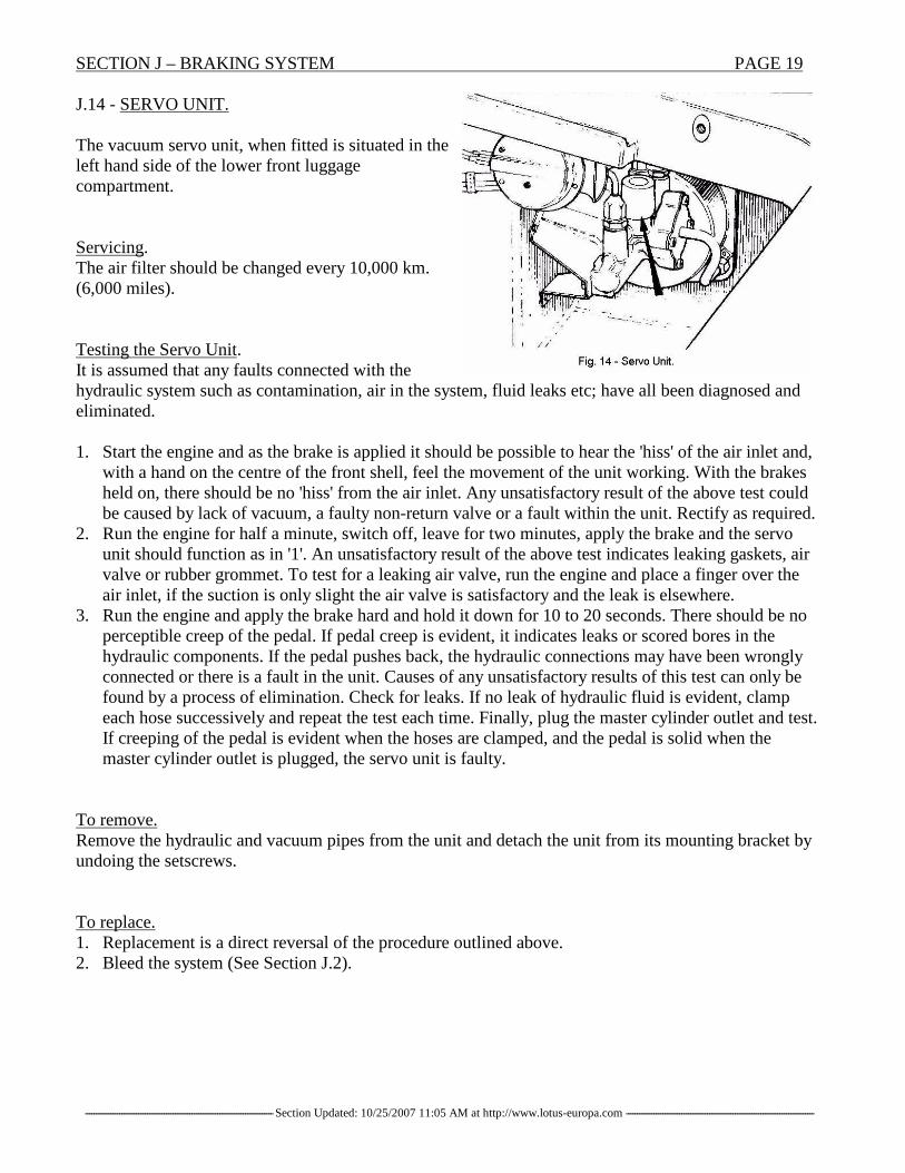
J.14 - SERVO UNIT.
The vacuum servo unit, when fitted is situated in theleft hand side of the lower front luggagecompartment.
Servicing.The air filter should be changed every 10,000 km.(6,000 miles).
Testing the Servo Unit.It is assumed that any faults connected with thehydraulic system such as contamination, air in the system, fluid leaks etc; have all been diagnosed andeliminated.
1. Start the engine and as the brake is applied it should be possible to hear the 'hiss' of the air inlet and,with a hand on the centre of the front shell, feel the movement of the unit working. With the brakesheld on, there should be no 'hiss' from the air inlet. Any unsatisfactory result of the above test couldbe caused by lack of vacuum, a faulty non-return valve or a fault within the unit. Rectify as required.
2. Run the engine for half a minute, switch off, leave for two minutes, apply the brake and the servounit should function as in '1'. An unsatisfactory result of the above test indicates leaking gaskets, airvalve or rubber grommet. To test for a leaking air valve, run the engine and place a finger over theair inlet, if the suction is only slight the air valve is satisfactory and the leak is elsewhere.
3. Run the engine and apply the brake hard and hold it down for 10 to 20 seconds. There should be noperceptible creep of the pedal. If pedal creep is evident, it indicates leaks or scored bores in thehydraulic components. If the pedal pushes back, the hydraulic connections may have been wronglyconnected or there is a fault in the unit. Causes of any unsatisfactory results of this test can only befound by a process of elimination. Check for leaks. If no leak of hydraulic fluid is evident, clampeach hose successively and repeat the test each time. Finally, plug the master cylinder outlet and test.If creeping of the pedal is evident when the hoses are clamped, and the pedal is solid when themaster cylinder outlet is plugged, the servo unit is faulty.
To remove.Remove the hydraulic and vacuum pipes from the unit and detach the unit from its mounting bracket byundoing the setscrews.
To replace.1. Replacement is a direct reversal of the procedure outlined above.2. Bleed the system (See Section J.2).

PAGE 20 SECTION J – BRAKING SYSTEM
----------------------------------------------------------------------------------------Section Updated: 10/25/2007 11:05 AM at http://www.lotus-europa.com ----------------------------------------------------------------------------------------
J.15 - HANDBRAKE.
The handbrake control is mounted under the facia on the driver’s side, and is of the 'umbrella' type. Tooperate the handbrake, pull the handle out.The ratchet will be heard to engage, and when the handle is out as far as it will go, it will lock inposition until released.To release the handbrake, pull on the handle to release the tension on the ratchet, push in the whiteserrated button on the top of the handle and release the handbrake.
To remove.1. Remove the two bolts retaining the handbrake control and detach the handbrake ratchet tube from thechassis-mounted handbrake lever.2. With the handbrake mechanism disconnected at the rear wheels, the intermediate cable may bedisconnected from the opposite end of the chassis mounted handbrake lever. The lever may be reachedby removing the large rubber plug from the floor of the upper front luggage compartment.3. Detach the spring from the end of the intermediate cable and remove the lock nuts. Thread theintermediate cable through the horseshoe, and remove the 'horseshoe' from the looped cable.Pull the cable through the slit in the rear of the chassis.
To replace.Replacement is a direct reversal of the procedure outlined above.When tightening the lower ratchet tube mounting bolt care must be taken to avoid crushing the ratchettube.For adjustment, see Section J.4.
J.16 - FAULT FINDING
FAULT CAUSE ACTION
Fade Incorrect pads. Distorted pads. Replace the pads, decrease theOverloaded vehicle. Excessive vehicle load or renew hydraulicbraking. Old hydraulic fluid. fluid as necessary.
Spongy Air in system. Pads or shoes Bleed system. Check masterPedal distorted. Weak master cylinder mounting and pads.
cylinder mounting.
Long Pedal Disc drum-out pushing pads Check that disc run-out is notTravel. back. Distorted damping excessive.
shims. Misplaced dust covers. Replace as necessary.
Brakes Brakes or handbrake maladjusted. Check the brake adjustment andbinding. No clearance at master cylinder handbrake linkage. Check for
pushrod. Seals swollen, clearance at the master cylinderSeized pistons. Shoe return Seized pistons or weak shoesprings weak or broken. springs. Repair or replaceServo faulty. parts as necessary. Fit new
dampers.
SECTION J – BRAKING SYSTEM PAGE 21
----------------------------------------------------------------------------------------Section Updated: 10/25/2007 11:05 AM at http://www.lotus-europa.com ----------------------------------------------------------------------------------------
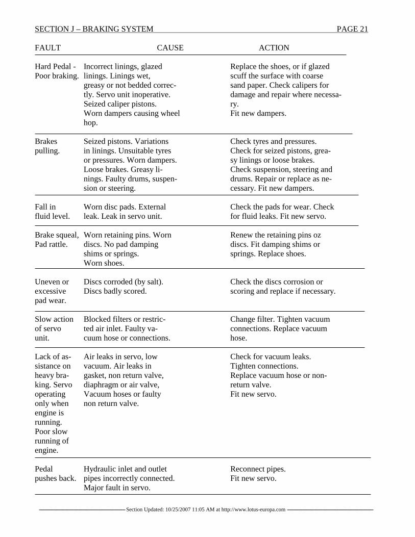
FAULT CAUSE ACTION
Hard Pedal - Incorrect linings, glazed Replace the shoes, or if glazedPoor braking. linings. Linings wet, scuff the surface with coarse
greasy or not bedded correc- sand paper. Check calipers fortly. Servo unit inoperative. damage and repair where necessa-Seized caliper pistons. ry.Worn dampers causing wheel Fit new dampers.hop.
Brakes Seized pistons. Variations Check tyres and pressures.pulling. in linings. Unsuitable tyres Check for seized pistons, grea-
or pressures. Worn dampers. sy linings or loose brakes.Loose brakes. Greasy li- Check suspension, steering andnings. Faulty drums, suspen- drums. Repair or replace as ne-sion or steering. cessary. Fit new dampers.
Fall in Worn disc pads. External Check the pads for wear. Checkfluid level. leak. Leak in servo unit. for fluid leaks. Fit new servo.
Brake squeal, Worn retaining pins. Worn Renew the retaining pins ozPad rattle. discs. No pad damping discs. Fit damping shims or
shims or springs. springs. Replace shoes.Worn shoes.
Uneven or Discs corroded (by salt). Check the discs corrosion orexcessive Discs badly scored. scoring and replace if necessary.pad wear.
Slow action Blocked filters or restric- Change filter. Tighten vacuumof servo ted air inlet. Faulty va- connections. Replace vacuumunit. cuum hose or connections. hose.
Lack of as- Air leaks in servo, low Check for vacuum leaks.sistance on vacuum. Air leaks in Tighten connections.heavy bra- gasket, non return valve, Replace vacuum hose or non-king. Servo diaphragm or air valve, return valve.operating Vacuum hoses or faulty Fit new servo.only when non return valve.engine isrunning.Poor slowrunning ofengine.
Pedal Hydraulic inlet and outlet Reconnect pipes.pushes back. pipes incorrectly connected. Fit new servo.
Major fault in servo.

PAGE 22 SECTION J – BRAKING SYSTEM
----------------------------------------------------------------------------------------Section Updated: 10/25/2007 11:05 AM at http://www.lotus-europa.com ----------------------------------------------------------------------------------------
ADDITIONAL INFORMATION
J.17 - SOVY DEVICE ADAPTOR
Commencing at Chassis No. 2090, a new Sovy device adaptor (Part No. 065 J 0104) has been fitted, inproduction to solve the problem of fluid leakage. Note that these adaptors are only fitted to cars havingthe Sovy device.
When fitting to cars prior to this chassis number, simply remove the existing adaptor and fit the newalloy adaptor. Check the fluid level after fitting.
If, after fitting the new adaptor, fluid seepage still occurs, it is recommended that a very small amount of'Hylomar SQ 32M' be applied to the threads at the top of the master cylinder. Leave a narrow band clearat the top to ensure that sealing compound does not enter the master cylinder, thus contaminating thehydraulic fluid.
Editors Notes:[1] Page 7 - Revised to indicate brake servo optional for both systems. [SV]


![LOTuS...our cover than a pristine yellow Lotus such as Tony Wheelers lovely Europa S [2] LOTuS & CLubMaN NOTeS February 2013 President’s pleasantries By Craig Chalmers, President,](https://img.pdfslide.us/doc/110x75/5f9e77eec9bd0956ab1e3067/lotus-our-cover-than-a-pristine-yellow-lotus-such-as-tony-wheelers-lovely-europa.jpg)