Embed Size (px)
Citation preview
CH 750 CRUZER
Zenith Aircraft Company www.zenithair.com
Elevator Assembly C75-TA-2 Page 1 of 21
Revision 1.0 (10/01/13) © 2013 Zenith Aircraft Co
Section C75-TA-2 Elevator
This manual has been prepared for assembly of the Elevator using match drilled parts. This photo assembly manual is intended as a supplement to the drawings. If there is any discrepancy between this manual and the drawings, the drawings supersede this manual. For more information on building standards and allowable tolerances see “Construction Standards for Zenair Light Aircraft” available from Zenith Aircraft Co.
CH 750 CRUZER
Zenith Aircraft Company www.zenithair.com
Elevator Assembly C75-TA-2 Page 2 of 21
Revision 1.0 (10/01/13) © 2013 Zenith Aircraft Co
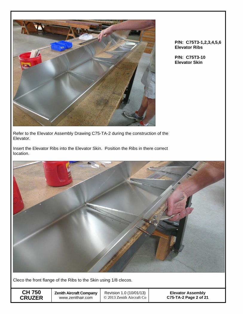
Refer to the Elevator Assembly Drawing C75-TA-2 during the construction of the Elevator. Insert the Elevator Ribs into the Elevator Skin. Position the Ribs in there correct location.
P/N: C75T3-1,2,3,4,5,6 Elevator Ribs P/N: C75T3-10 Elevator Skin
Cleco the front flange of the Ribs to the Skin using 1/8 clecos.
CH 750 CRUZER
Zenith Aircraft Company www.zenithair.com
Elevator Assembly C75-TA-2 Page 3 of 21
Revision 1.0 (10/01/13) © 2013 Zenith Aircraft Co
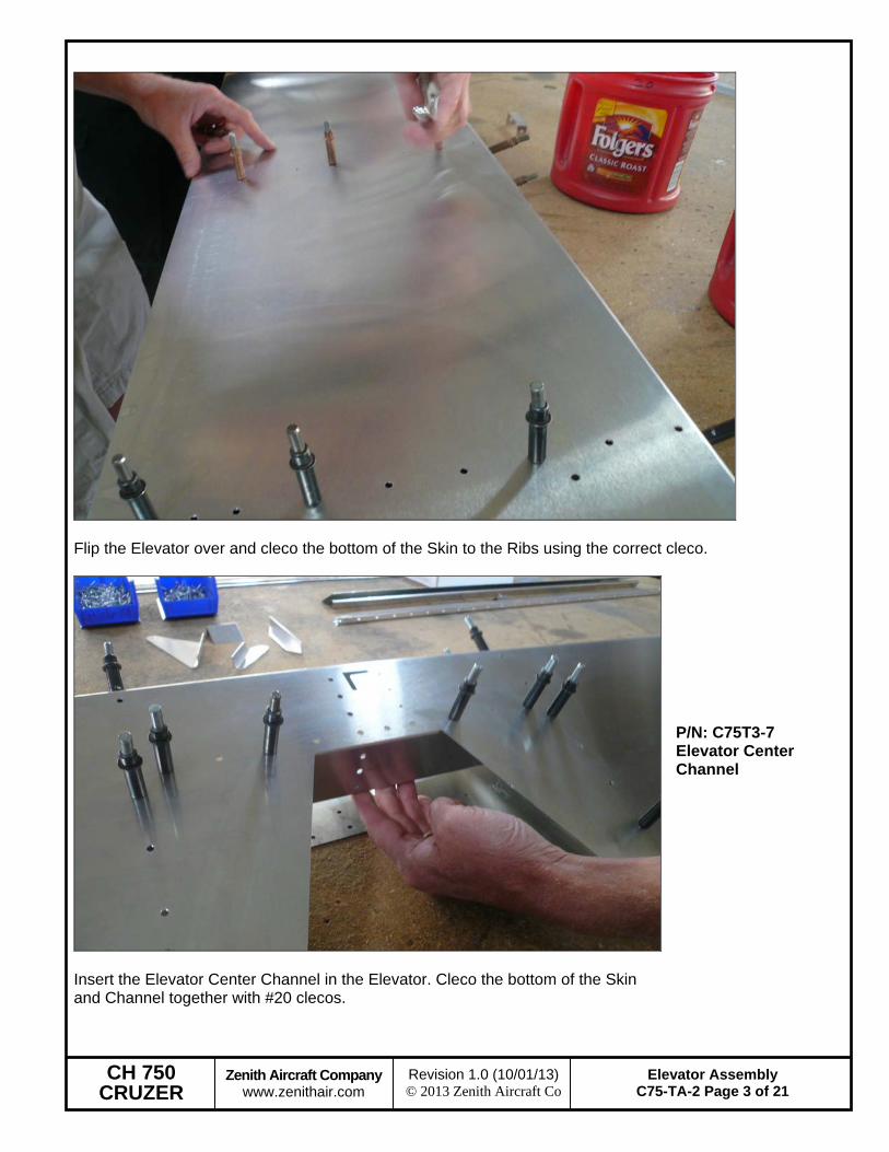
Flip the Elevator over and cleco the bottom of the Skin to the Ribs using the correct cleco.
Insert the Elevator Center Channel in the Elevator. Cleco the bottom of the Skin and Channel together with #20 clecos.
P/N: C75T3-7 Elevator Center Channel
CH 750 CRUZER
Zenith Aircraft Company www.zenithair.com
Elevator Assembly C75-TA-2 Page 4 of 21
Revision 1.0 (10/01/13) © 2013 Zenith Aircraft Co
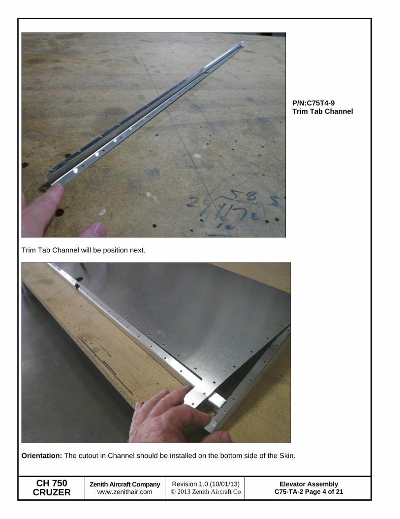
Trim Tab Channel will be position next.
P/N:C75T4-9 Trim Tab Channel
Orientation: The cutout in Channel should be installed on the bottom side of the Skin.
CH 750 CRUZER
Zenith Aircraft Company www.zenithair.com
Elevator Assembly C75-TA-2 Page 5 of 21
Revision 1.0 (10/01/13) © 2013 Zenith Aircraft Co
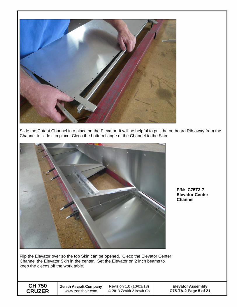
Slide the Cutout Channel into place on the Elevator. It will be helpful to pull the outboard Rib away from the Channel to slide it in place. Cleco the bottom flange of the Channel to the Skin.
Flip the Elevator over so the top Skin can be opened. Cleco the Elevator Center Channel the Elevator Skin in the center. Set the Elevator on 2 inch beams to keep the clecos off the work table.
P/N: C75T3-7 Elevator Center Channel
CH 750 CRUZER
Zenith Aircraft Company www.zenithair.com
Elevator Assembly C75-TA-2 Page 6 of 21
Revision 1.0 (10/01/13) © 2013 Zenith Aircraft Co
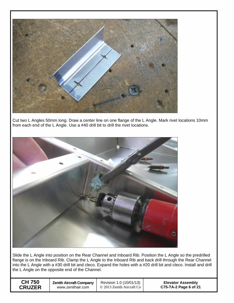
Cut two L Angles 50mm long. Draw a center line on one flange of the L Angle. Mark rivet locations 10mm from each end of the L Angle. Use a #40 drill bit to drill the rivet locations.
Slide the L Angle into position on the Rear Channel and Inboard Rib. Position the L Angle so the predrilled flange is on the Inboard Rib. Clamp the L Angle to the Inboard Rib and back drill through the Rear Channel into the L Angle with a #30 drill bit and cleco. Expand the holes with a #20 drill bit and cleco. Install and drill the L Angle on the opposite end of the Channel.
CH 750 CRUZER
Zenith Aircraft Company www.zenithair.com
Elevator Assembly C75-TA-2 Page 7 of 21
Revision 1.0 (10/01/13) © 2013 Zenith Aircraft Co
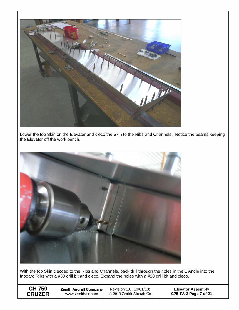
Lower the top Skin on the Elevator and cleco the Skin to the Ribs and Channels. Notice the beams keeping the Elevator off the work bench.
With the top Skin clecoed to the Ribs and Channels, back drill through the holes in the L Angle into the Inboard Ribs with a #30 drill bit and cleco. Expand the holes with a #20 drill bit and cleco.
CH 750 CRUZER
Zenith Aircraft Company www.zenithair.com
Elevator Assembly C75-TA-2 Page 8 of 21
Revision 1.0 (10/01/13) © 2013 Zenith Aircraft Co
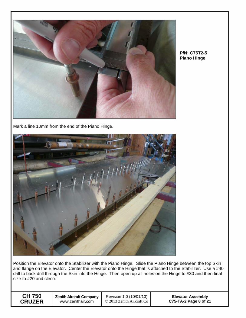
Mark a line 10mm from the end of the Piano Hinge.
P/N: C75T2-5 Piano Hinge
Position the Elevator onto the Stabilizer with the Piano Hinge. Slide the Piano Hinge between the top Skin and flange on the Elevator. Center the Elevator onto the Hinge that is attached to the Stabilizer. Use a #40 drill to back drill through the Skin into the Hinge. Then open up all holes on the Hinge to #30 and then final size to #20 and cleco.
CH 750 CRUZER
Zenith Aircraft Company www.zenithair.com
Elevator Assembly C75-TA-2 Page 9 of 21
Revision 1.0 (10/01/13) © 2013 Zenith Aircraft Co
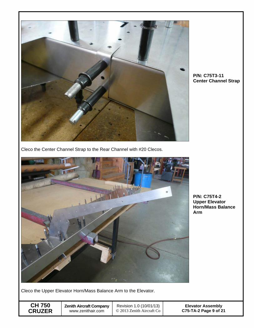
Cleco the Center Channel Strap to the Rear Channel with #20 Clecos.
P/N: C75T3-11 Center Channel Strap
Cleco the Upper Elevator Horn/Mass Balance Arm to the Elevator.
P/N: C75T4-2 Upper Elevator Horn/Mass Balance Arm
CH 750 CRUZER
Zenith Aircraft Company www.zenithair.com
Elevator Assembly C75-TA-2 Page 10 of 21
Revision 1.0 (10/01/13) © 2013 Zenith Aircraft Co
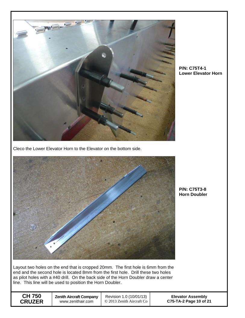
Cleco the Lower Elevator Horn to the Elevator on the bottom side.
P/N: C75T4-1 Lower Elevator Horn
Layout two holes on the end that is cropped 20mm. The first hole is 6mm from the end and the second hole is located 8mm from the first hole. Drill these two holes as pilot holes with a #40 drill. On the back side of the Horn Doubler draw a center line. This line will be used to position the Horn Doubler.
P/N: C75T3-8 Horn Doubler
CH 750 CRUZER
Zenith Aircraft Company www.zenithair.com
Elevator Assembly C75-TA-2 Page 11 of 21
Revision 1.0 (10/01/13) © 2013 Zenith Aircraft Co
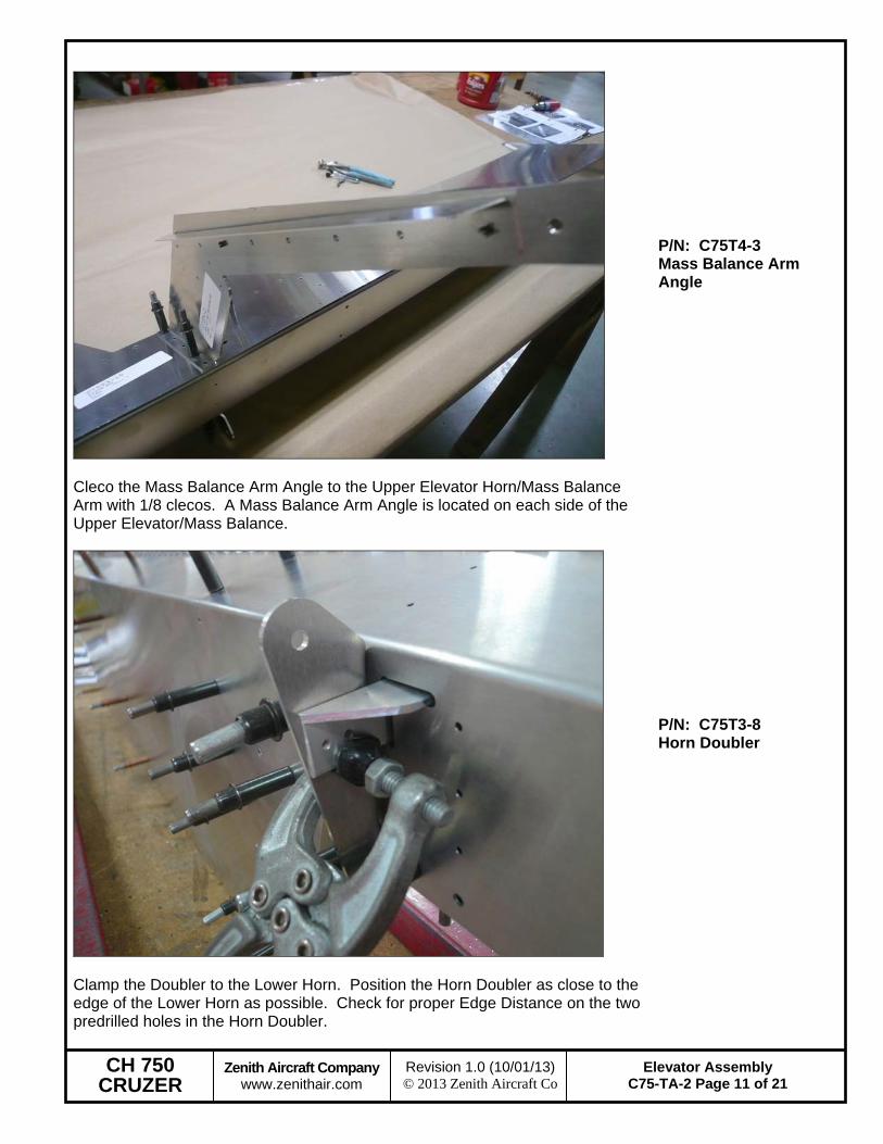
Cleco the Mass Balance Arm Angle to the Upper Elevator Horn/Mass Balance Arm with 1/8 clecos. A Mass Balance Arm Angle is located on each side of the Upper Elevator/Mass Balance.
P/N: C75T4-3 Mass Balance Arm Angle
Clamp the Doubler to the Lower Horn. Position the Horn Doubler as close to the edge of the Lower Horn as possible. Check for proper Edge Distance on the two predrilled holes in the Horn Doubler.
P/N: C75T3-8 Horn Doubler
CH 750 CRUZER
Zenith Aircraft Company www.zenithair.com
Elevator Assembly C75-TA-2 Page 12 of 21
Revision 1.0 (10/01/13) © 2013 Zenith Aircraft Co
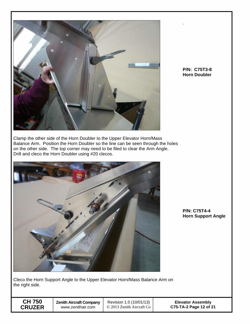
Clamp the other side of the Horn Doubler to the Upper Elevator Horn/Mass Balance Arm. Position the Horn Doubler so the line can be seen through the holes on the other side. The top corner may need to be filed to clear the Arm Angle. Drill and cleco the Horn Doubler using #20 clecos.
. P/N: C75T3-8 Horn Doubler
Cleco the Horn Support Angle to the Upper Elevator Horn/Mass Balance Arm on the right side.
P/N: C75T4-4 Horn Support Angle
CH 750 CRUZER
Zenith Aircraft Company www.zenithair.com
Elevator Assembly C75-TA-2 Page 13 of 21
Revision 1.0 (10/01/13) © 2013 Zenith Aircraft Co
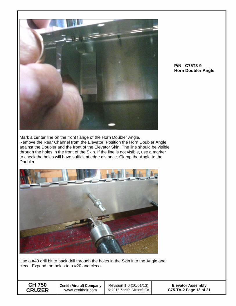
Mark a center line on the front flange of the Horn Doubler Angle. Remove the Rear Channel from the Elevator. Position the Horn Doubler Angle against the Doubler and the front of the Elevator Skin. The line should be visible through the holes in the front of the Skin. If the line is not visible, use a marker to check the holes will have sufficient edge distance. Clamp the Angle to the Doubler.
P/N: C75T3-9 Horn Doubler Angle
Use a #40 drill bit to back drill through the holes in the Skin into the Angle and cleco. Expand the holes to a #20 and cleco.
CH 750 CRUZER
Zenith Aircraft Company www.zenithair.com
Elevator Assembly C75-TA-2 Page 14 of 21
Revision 1.0 (10/01/13) © 2013 Zenith Aircraft Co
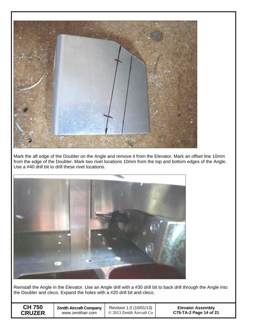
Mark the aft edge of the Doubler on the Angle and remove it from the Elevator. Mark an offset line 10mm from the edge of the Doubler. Mark two rivet locations 10mm from the top and bottom edges of the Angle. Use a #40 drill bit to drill these rivet locations.
Reinstall the Angle in the Elevator. Use an Angle drill with a #30 drill bit to back drill through the Angle into the Doubler and cleco. Expand the holes with a #20 drill bit and cleco.
CH 750 CRUZER
Zenith Aircraft Company www.zenithair.com
Elevator Assembly C75-TA-2 Page 15 of 21
Revision 1.0 (10/01/13) © 2013 Zenith Aircraft Co
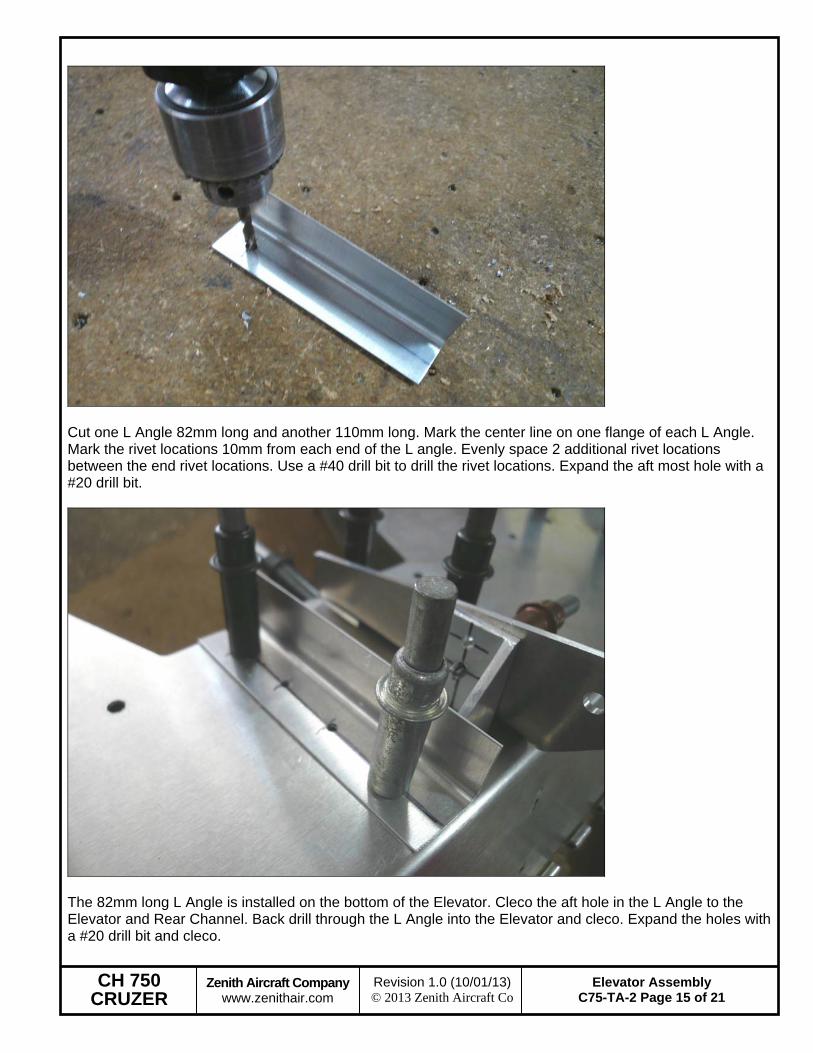
Cut one L Angle 82mm long and another 110mm long. Mark the center line on one flange of each L Angle. Mark the rivet locations 10mm from each end of the L angle. Evenly space 2 additional rivet locations between the end rivet locations. Use a #40 drill bit to drill the rivet locations. Expand the aft most hole with a #20 drill bit.
The 82mm long L Angle is installed on the bottom of the Elevator. Cleco the aft hole in the L Angle to the Elevator and Rear Channel. Back drill through the L Angle into the Elevator and cleco. Expand the holes with a #20 drill bit and cleco.
CH 750 CRUZER
Zenith Aircraft Company www.zenithair.com
Elevator Assembly C75-TA-2 Page 16 of 21
Revision 1.0 (10/01/13) © 2013 Zenith Aircraft Co
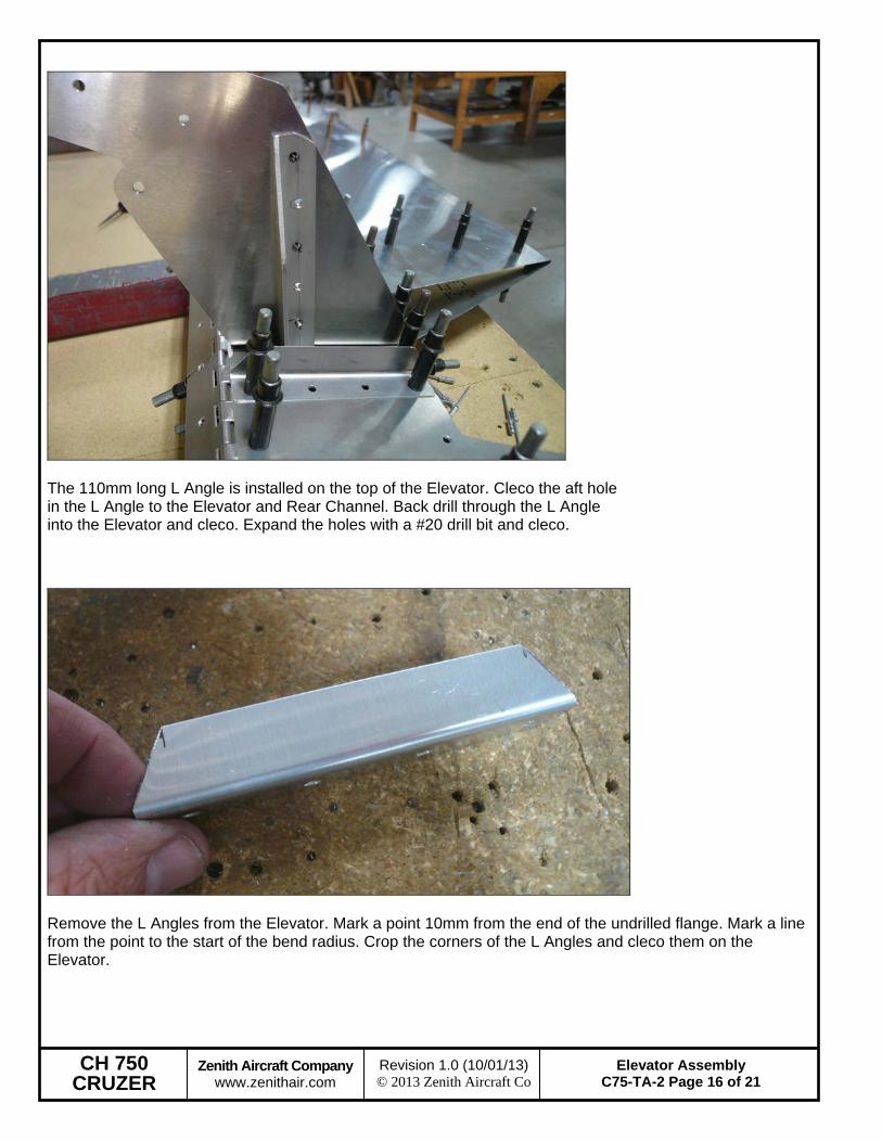
The 110mm long L Angle is installed on the top of the Elevator. Cleco the aft hole in the L Angle to the Elevator and Rear Channel. Back drill through the L Angle into the Elevator and cleco. Expand the holes with a #20 drill bit and cleco.
Remove the L Angles from the Elevator. Mark a point 10mm from the end of the undrilled flange. Mark a line from the point to the start of the bend radius. Crop the corners of the L Angles and cleco them on the Elevator.
CH 750 CRUZER
Zenith Aircraft Company www.zenithair.com
Elevator Assembly C75-TA-2 Page 17 of 21
Revision 1.0 (10/01/13) © 2013 Zenith Aircraft Co
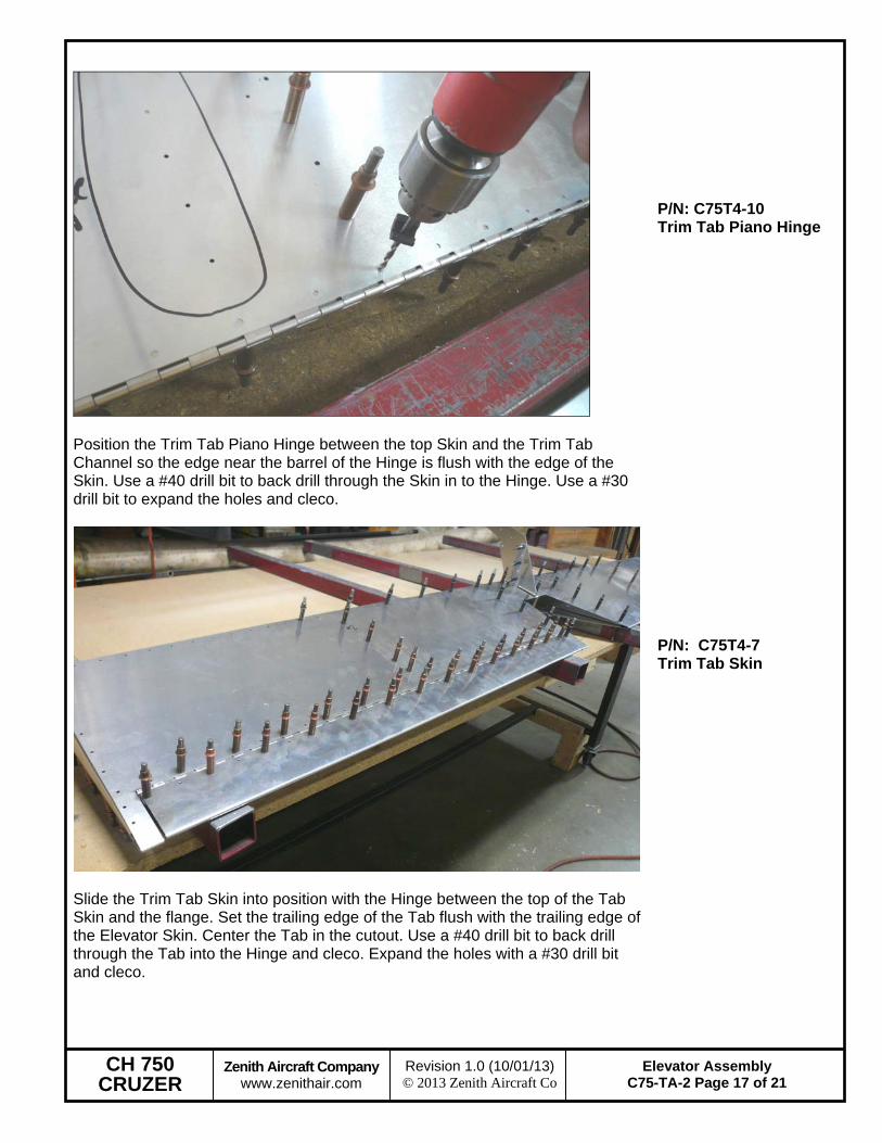
Position the Trim Tab Piano Hinge between the top Skin and the Trim Tab Channel so the edge near the barrel of the Hinge is flush with the edge of the Skin. Use a #40 drill bit to back drill through the Skin in to the Hinge. Use a #30 drill bit to expand the holes and cleco.
P/N: C75T4-10 Trim Tab Piano Hinge
Slide the Trim Tab Skin into position with the Hinge between the top of the Tab Skin and the flange. Set the trailing edge of the Tab flush with the trailing edge of the Elevator Skin. Center the Tab in the cutout. Use a #40 drill bit to back drill through the Tab into the Hinge and cleco. Expand the holes with a #30 drill bit and cleco.
P/N: C75T4-7 Trim Tab Skin
CH 750 CRUZER
Zenith Aircraft Company www.zenithair.com
Elevator Assembly C75-TA-2 Page 18 of 21
Revision 1.0 (10/01/13) © 2013 Zenith Aircraft Co
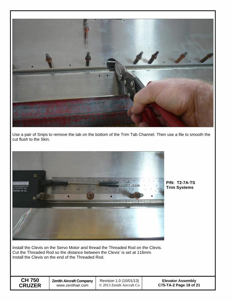
Use a pair of Snips to remove the tab on the bottom of the Trim Tab Channel. Then use a file to smooth the cut flush to the Skin.
Install the Clevis on the Servo Motor and thread the Threaded Rod on the Clevis. Cut the Threaded Rod so the distance between the Clevis’ is set at 116mm. Install the Clevis on the end of the Threaded Rod.
P/N: T2-7A-TS Trim Systems
CH 750 CRUZER
Zenith Aircraft Company www.zenithair.com
Elevator Assembly C75-TA-2 Page 19 of 21
Revision 1.0 (10/01/13) © 2013 Zenith Aircraft Co
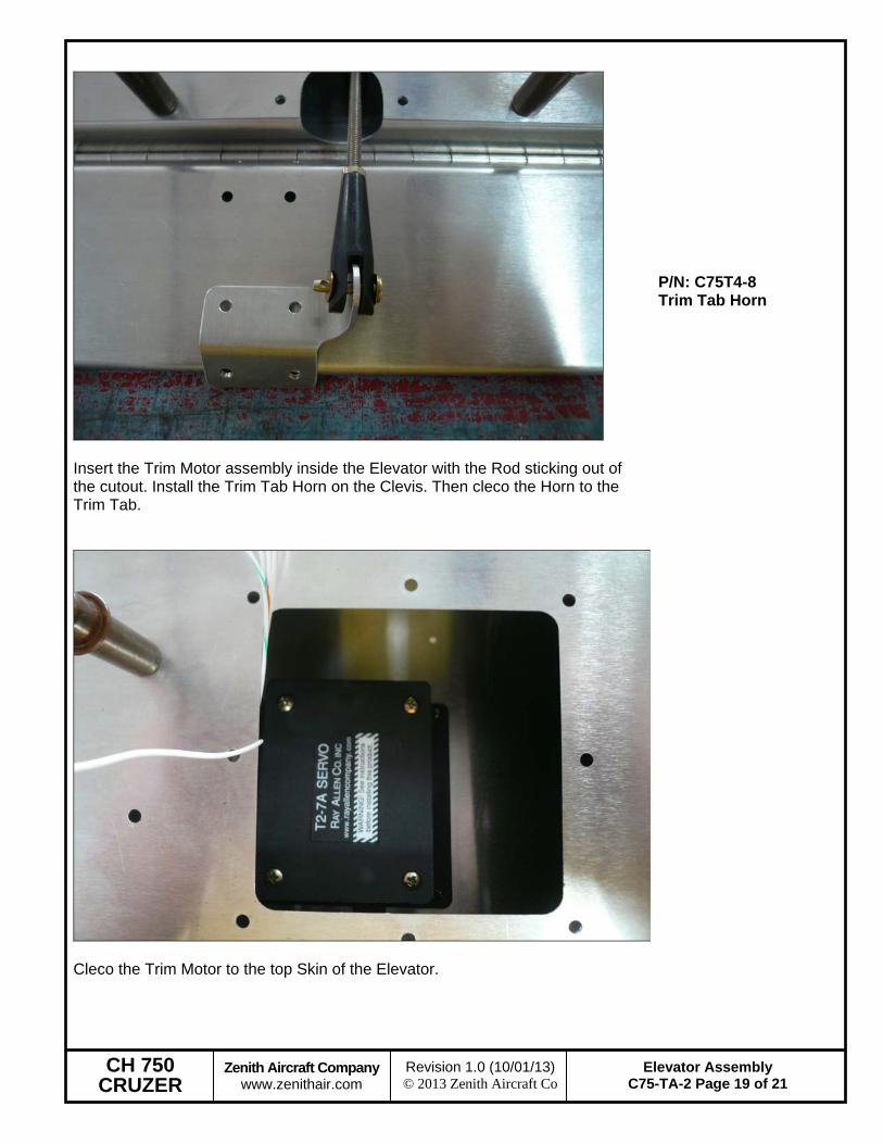
Insert the Trim Motor assembly inside the Elevator with the Rod sticking out of the cutout. Install the Trim Tab Horn on the Clevis. Then cleco the Horn to the Trim Tab.
P/N: C75T4-8 Trim Tab Horn
Cleco the Trim Motor to the top Skin of the Elevator.

CH 750 CRUZER
Zenith Aircraft Company www.zenithair.com
Elevator Assembly C75-TA-2 Page 20 of 21
Revision 1.0 (10/01/13) © 2013 Zenith Aircraft Co
Measure and cut a “L” Angle to 268mm. Slide the Angle through the Trim Motor Access hole. Position the Angle on the left side of the Motor. See drawing C75-TA-2 upper left side of drawing.
Back drilling the “L’” Angle next the Trim Motor. P/N: “L” Angle
Layout 4 evenly spaced Cradle Cable Tie Mounts to secure the Trim Wire. Trim Wire is secured using a tie wrap to the Cradle Cable Tie Mounts. Finish wiring the Trim Motor and securing the wires. Safety Wire each end on the Paino Hinge for the Elevator and Trim Tab using .032 Safety wire. This will keep the rod from sliding out on each end.
Access Cover can be riveted to the Elevator Skin. P/N: 11-03987 Cradle Cable Tie Mounts

CH 750 CRUZER
Zenith Aircraft Company www.zenithair.com
Elevator Assembly C75-TA-2 Page 21 of 21
Revision 1.0 (10/01/13) © 2013 Zenith Aircraft Co
The Elevator and Stabilizer can be mounted together and painted as one unit. After the assembly has been painted the Elevator can be Mass Balanced before mounting on the Fuselage. Balancing the control section will be shown later in the Drawings and Manuals.