Embed Size (px)
Citation preview
1
SECTION A17 BUSINESS, ENTERPRISE CORRIDOR & GENERAL INDUSTRIAL ZONES
Version 1.2
2
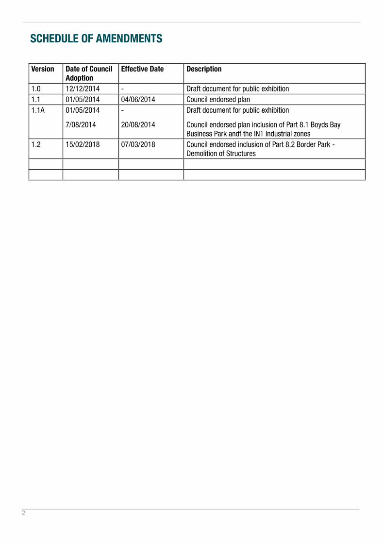
SCHEDULE OF AMENDMENTS
Version Date of Council Adoption
Effective Date Description
1.0 12/12/2014 - Draft document for public exhibition1.1 01/05/2014 04/06/2014 Council endorsed plan1.1A 01/05/2014
7/08/2014
-
20/08/2014
Draft document for public exhibition
Council endorsed plan inclusion of Part 8.1 Boyds Bay Business Park andf the IN1 Industrial zones
1.2 15/02/2018 07/03/2018 Council endorsed inclusion of Part 8.2 Border Park - Demolition of Structures

3
SECTION A17 BUSINESS, ENTERPRISE CORRIDOR & GENERAL INDUSTRIAL ZONES 1
1. Introduction 6
1.1. Purpose of this Section 6
1.2. Land to which this section applies 6
1.3. How to use this Section 7
2. Business Zones Land use 8
2.1. Business Development Zone (B5) 8
2.2. Enterprise Corridor Zone (B6) 9
2.3. Business Park Zone (B7) 9
2.4. General Industrial Zone (IN1) 11
2.5. PART 1 - SHIRE WIDE PROVISIONS 12
3. Site Design 12
3.1. Site Analysis 12
3.2. Urban Design 16
3.3. Topography, Cut and Fill 18
4. Building Envelope 21
4.1. Setbacks 21
4.2. Site Coverage and Landscape Area 24
4.3. Building Heights 25
5. Building Design 26
5.1. Designing for the Tweed Climate 26
5.2. Building Form and Materials 28
5.3. Overshadowing 34
5.4. Views and Visual Amenity 35
4
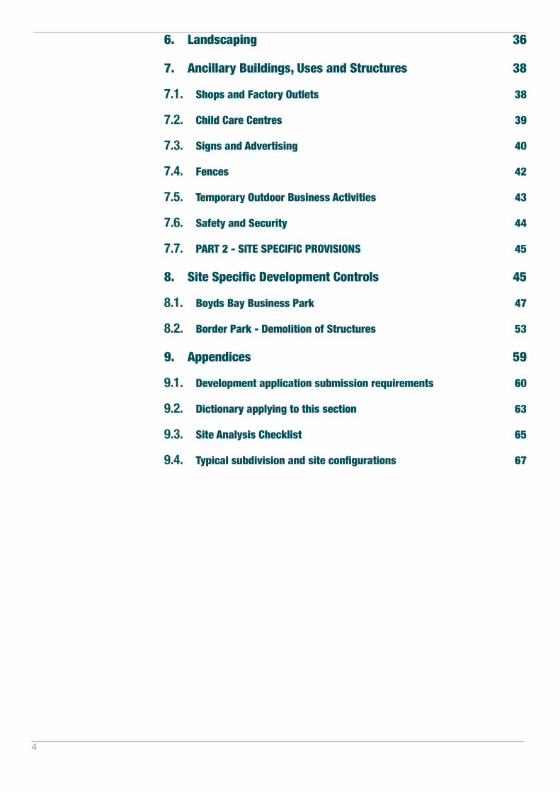
6. Landscaping 36
7. Ancillary Buildings, Uses and Structures 38
7.1. Shops and Factory Outlets 38
7.2. Child Care Centres 39
7.3. Signs and Advertising 40
7.4. Fences 42
7.5. Temporary Outdoor Business Activities 43
7.6. Safety and Security 44
7.7. PART 2 - SITE SPECIFIC PROVISIONS 45
8. Site Specific Development Controls 45
8.1. Boyds Bay Business Park 47
8.2. Border Park - Demolition of Structures 53
9. Appendices 59
9.1. Development application submission requirements 60
9.2. Dictionary applying to this section 63
9.3. Site Analysis Checklist 65
9.4. Typical subdivision and site configurations 67

5
Figure 1.1 SECTION A17 STRUCTURE
SECTION A17 BUSINESS, ENTERPRISE
CORRIDOR & GENERAL INDUSTRIAL ZONES
Landscaping
Site Design
Introduction
Business & Industrial Land Uses
Building Envelope
Building Design
Ancillary Uses
PART 2
SITE SPECIFIC PROVISIONSObjectives and controls which relate to specific sites which need to be addressed in addition to
the Shire Wide Provisions.
PART 1
SHIRE WIDE PROVISIONSObjectives and controls which relate to all
business development sites within Tweed Shire.

6
1. Introduction
1.1. Purpose of this Section
The purpose of this Section is to provide a planning framework that establishes Council’s aims, objectives and controls for site design, building envelope and design, landscaping and ancillary uses within the Business Development, Enterprise Corridor, Business Park and General Industrial zones.
Aims of this Section
A1. Contribute to the growth and character of Tweed Shire’s business, enterprise and industrial precincts.
A2. Facilitate coordinated business, enterprise and industrial precincts which maximise employment opportunities through site efficiency and amenity.
A3. Facilitate the development of sites that minimises under utilisation or sterilisation of land through poor site planning, design and unsuitable land uses.
A4. Achieve an attractive and sustainable built form which responds to the features of the site and the Tweed’s subtropical climate.
Objectives of this Section
O1. Encourage establishing employment and land use synergies and integration by supporting built form variety, diversity and co-location of infrastructure.
O2. Establish efficient site planning, land use and built form through an investigative site analysis process.
O3. Ensure the utilisation of land is maximised by establishing an integrated suite of design controls and requiring design responses directly harness the attributes of the site identified through a thorough site analysis.
O4. Establish a high quality built form character and urban environment through best practice site planning and urban design provisions.
O5. Establish specific urban design provisions that create human scale outcomes, attractive streetscapes and moderating building mass for large floorplate development.
O6. Encourage the inclusion of design features that provide high quality environments for staff and customers.
O7. Ensure comfortable microclimates are created through adequate landscaping and the provision of water sensitive urban design.
O8. Ensure that development with an interface to zone or precinct boundaries responds to potential external conflicts that arise from a land use and built form change.
O9. Encourage the implementation of active and passive design processes that sustainably respond to the sites climatic conditions.
O10. Encourage the integration of fine-grain, ancillary and supplementary land uses within business and enterprise zones.
1.2. Land to which this section applies
This Section applies to all development within the B5, B6, B7 and IN1 zones, to the extent of inconsistency with a development provision contained in the Tweed Local Environmental
7
INTRODUCTION
Plans (TLEP) or Section B of the Tweed Development Control Plan (TDCP).
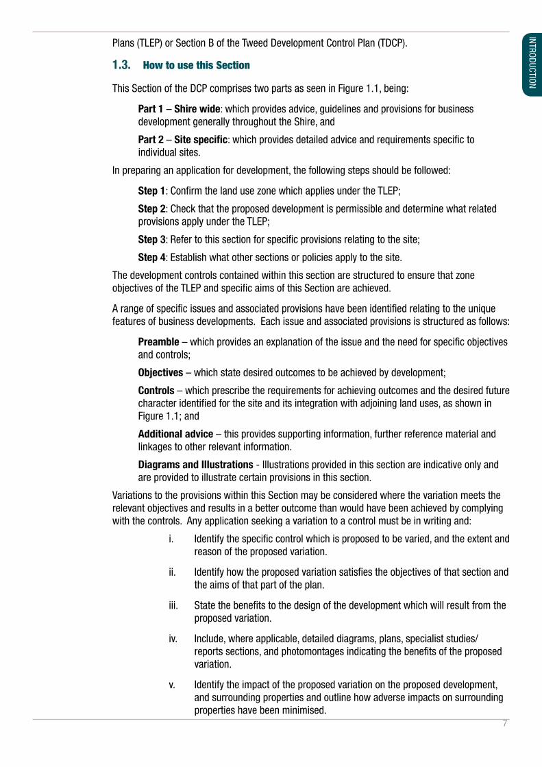
1.3. How to use this Section
This Section of the DCP comprises two parts as seen in Figure 1.1, being:
Part 1 – Shire wide: which provides advice, guidelines and provisions for business development generally throughout the Shire, and
Part 2 – Site specific: which provides detailed advice and requirements specific to individual sites.
In preparing an application for development, the following steps should be followed:
Step 1: Confirm the land use zone which applies under the TLEP;
Step 2: Check that the proposed development is permissible and determine what related provisions apply under the TLEP;
Step 3: Refer to this section for specific provisions relating to the site;
Step 4: Establish what other sections or policies apply to the site.
The development controls contained within this section are structured to ensure that zone objectives of the TLEP and specific aims of this Section are achieved.
A range of specific issues and associated provisions have been identified relating to the unique features of business developments. Each issue and associated provisions is structured as follows:
Preamble – which provides an explanation of the issue and the need for specific objectives and controls;
Objectives – which state desired outcomes to be achieved by development;
Controls – which prescribe the requirements for achieving outcomes and the desired future character identified for the site and its integration with adjoining land uses, as shown in Figure 1.1; and
Additional advice – this provides supporting information, further reference material and linkages to other relevant information.
Diagrams and Illustrations - Illustrations provided in this section are indicative only and are provided to illustrate certain provisions in this section.
Variations to the provisions within this Section may be considered where the variation meets the relevant objectives and results in a better outcome than would have been achieved by complying with the controls. Any application seeking a variation to a control must be in writing and:
i. Identify the specific control which is proposed to be varied, and the extent and reason of the proposed variation.
ii. Identify how the proposed variation satisfies the objectives of that section and the aims of that part of the plan.
iii. State the benefits to the design of the development which will result from the proposed variation.
iv. Include, where applicable, detailed diagrams, plans, specialist studies/reports sections, and photomontages indicating the benefits of the proposed variation.
v. Identify the impact of the proposed variation on the proposed development, and surrounding properties and outline how adverse impacts on surrounding properties have been minimised.

8
2. Business Zones Land use
Preamble
While a rapidly growing residential population can contribute to a strong and vibrant economy, the demography and characteristics of the Tweed population point to a need for diversification in employment opportunities.
The ability of a business development to positively impact these trends is an important component of the benefits expected from such development.
The Tweed Community Strategic Plan 2011-2021 under the Theme of Strengthening the Economy identified a range of community priorities relating to economic development, which included:
• Creating employment opportunities.
• Attracting industry to the Tweed.
• Rejuvenating Tweed Heads CBD.
A key component of improving standards of living and job creation is the adoption of innovative ideas and technologies in services, products and manufacturing processes. The creation of a strong and diverse Tweed economy will be enhanced by the integration of knowledge-based industry which is characterised by technological innovation, e-commerce, digital transformation, higher Education and skills, and open trade.
There is a real need for high quality locations with integrated knowledge and technology based industries close to a skilled labour force. Of the working population, a relatively high proportion of the Tweed employed resident population travel into South East Queensland daily to work.
Under-represented industries in the Tweed include knowledge-based service industries, goods-producing industries, finance and insurance services, aged care and health services, wholesale trade, manufacturing and property and business services (TUELRS, 2009).
This section of the DCP seeks to support the creation of a contemporary local economy strong and vibrant, capable of accommodating a range of compatible development types, and able to adjust to transitions in market requirements without excessive, prescriptive based controls.
2.1. Business Development Zone (B5)
The business development zone represents a wide range of business and light industrial land uses including those that typically require large floor areas. Whilst these uses don’t necessarily need to be located within local centres, they should be strategically located to enable the support and viability of those local centres including providing local employment opportunities.
Within the Tweed context, business development sites are areas zoned to facilitate a broad mix of employment generating uses including, but not limited to, bulky goods development, general industry, hardware and building suppliers, light industry, timber yards, warehouse and distributor centres, wholesaler supplies and the like. Ancillary services such as child care centres, take away food and drink and services stations are also typical uses within this zone.
9
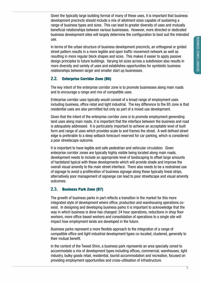
Given the typically large building format of many of these uses, it is important that business development precincts should include a mix of allotment sizes capable of sustaining a range of business types and sizes. This can lead to greater diversity of uses and mutually beneficial relationships between various businesses. However, more directed or dedicated business development sites will largely determine the configuration to best suit the intended use.
In terms of the urban structure of business development precincts, an orthogonal or grided street pattern results in a more legible and open traffic movement network as well as resulting in more regular block shapes and sizes. This makes it easier to apply passive design principles to future buildings. Varying lot sizes across a subdivision also results in more diversity and variety of uses and establishes opportunities for symbiotic business relationships between larger and smaller start up businesses.
2.2. Enterprise Corridor Zone (B6)
The key intent of the enterprise corridor zone is to promote businesses along main roads and to encourage a range and mix of compatible uses.
Enterprise corridor uses typically would consist of a broad range of employment uses including business, office retail and light industrial. The key difference to the B5 zone is that residential uses are also permitted but only as part of a mixed use development.
Given that the intent of the enterprise corridor zone is to promote employment generating land uses along main roads, it is important that the interface between the business and road is adequately addressed. It is particularly important to achieve an acceptable level of built form and range of uses which provides scale to and frames the street. A well defined street edge is preferable to a deep setback forecourt reserved for car parking, which is considered a poor streetscape outcome.
It is important to have legible and safe pedestrian and vehicular circulation. Given enterprise corridor zones are typically highly visible being located along main roads, development needs to include an appropriate level of landscaping to offset large amounts of hardstand typical with these developments which will provide shade and improve the overall visual amenity to the main street interface. There also needs to be a restrained use of signage to avoid a proliferation of business signage along these typically lineal strips, alternatively poor management of signange can lead to poor streetscape and visual amenity outcomes.
2.3. Business Park Zone (B7)
The growth of business parks in part reflects a transition in the market for this more integrated style of development where office, production and warehousing operations co-exist. In designing and developing business parks it is important to acknowledge that the way in which business is done has changed: 24 hour operations, reductions in shop floor workers, more office based workers and consolidation of operations to a single site will impact how employment lands are developed in the future.
Business parks represent a more flexible approach to the integration of a range of compatible office and light industrial development types co-located, clustered, generally to their mutual benefit.
In the context of the Tweed Shire, a business park represents an area specially zoned to accommodate a mix of development types including offices, commercial, warehouses, light industry, bulky goods retail, residential, tourist accommodation and recreation, focused on providing employment opportunities and cross-utilisation of infrastructure.
BUSINESS ZONES LANDUSE
10
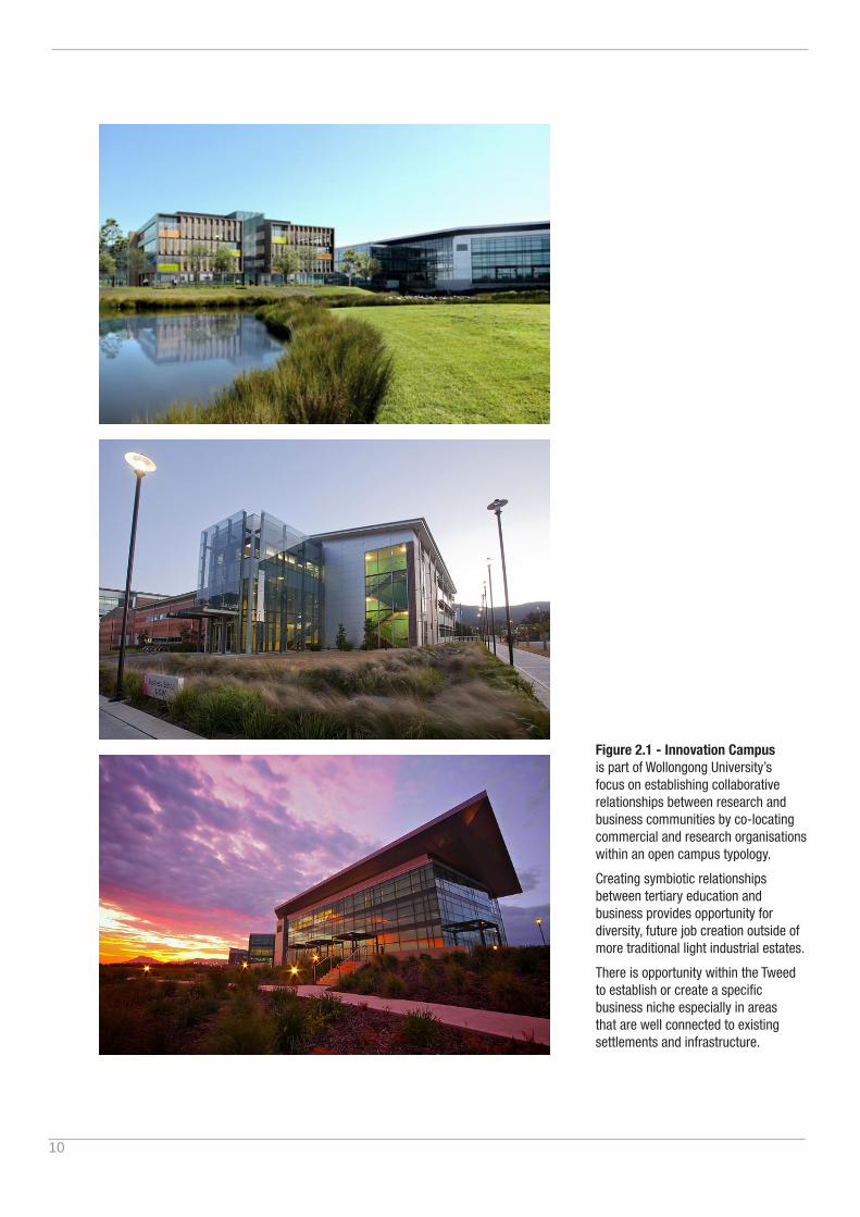
Figure 2.1 - Innovation Campus is part of Wollongong University’s focus on establishing collaborative relationships between research and business communities by co-locating commercial and research organisations within an open campus typology.
Creating symbiotic relationships between tertiary education and business provides opportunity for diversity, future job creation outside of more traditional light industrial estates.
There is opportunity within the Tweed to establish or create a specific business niche especially in areas that are well connected to existing settlements and infrastructure.
11
This incorporates the aspect of a strong and unified public domain and place-based planning. Place-based planning is a means of shaping the future of a site or locality concentrating on the overall amenity and integration, the form and character of individual buildings and the overall concept, instead of focusing only on conventional categories of land use.
Given the diversity of business park opportunities available in terms of location, land size, constraints and contextual considerations there is opportunity for a range of business niches to be developed within the Tweed.
The overriding ‘business theme’ or business niche of a newly proposed business park should be justified not only through a site analysis and land use planning process, but through sound economic planning and modelling demonstrating the ‘best fit’ of the proposal with the site’s physical and economic context.
It is also important to match business park uses within the broader strategic context. For example, land available close to the Gold Coast Airport and Southern Cross University may be appropriate for aviation and education centred land uses which support these existing industry. Sites which are located closer to the national highway may more appropriately serve bulky goods, transport or logistics land uses. Other sites which adjoin residential settlements or that are topographically constrained may be more suited to smaller scale incubator business and live-work opportunities.
2.4. General Industrial Zone (IN1)
The General Industrial zone accommodates a range of industrial and warehouse uses and seeks to encourage employment opportunities. Like the B5 zone, development within the IN1 zone typically includes buildings with large floor areas and greater needs for on-site vehicle servicing. Accordingly larger minimum lot sizes apply and additional consideration of how development integrates within the wider landscape may be required.
Whilst the development form may be similar to the B5 zone, the General Industrial zone is not a suitable location for retail development and other non-industrial land uses outside of land uses that serve the day to day needs of workers in the area. Such land uses may include neighbourhood shops, take away food and drink and child care centres. Given the potential impacts of industrial development and the sensitivities of ancillary and facilitating land uses, a strategic approach to subdivision and building design is required to limit interface impacts and enable the seamless evolution of land uses within a General Industrial precinct over time.
BUSINESS ZONES LANDUSE

12
PART 1 - SHIRE WIDE PROVISIONS
3. Site Design
3.1. Site Analysis
Preamble:
Site analysis and the subsequent preparation of a responding development outcome is an essential step in the planning process. Undertaking a sound site analysis is particularly pertinent for business style development where large buildings, noise and traffic can significantly impact adjoining land uses.
A well thought out site analysis plan will lead to more efficient development of a site, be compatible with relevant provisions and guidelines and enable impacts and benefits to be more fully assessed and endorsed early in the process, leading to more certainty about outcomes for the proponent, Council and the community.
The first step in good design is to understand the character, context and attributes of the site and the locality. Site analysis and design response comprises two parts:
1. assessment of the existing condition, opportunities and constraints of a particular site, and
2. design response to the characteristics, the opportunities, constraints, unique features or potential hazards of a particular site.
Development designed to site conditions is more likely to:
• deliver development that is appropriate to a given site in terms of best use of the site from a contextual as well as an environmental and employment generating perspective;
• enhances the amenity of the site and locality;
• improve the overall comfort levels of buildings;
• enhances the sense of place;
• reinforce the role and character of the Tweed more broadly;
• improves the quality of the natural and built environment for users and employees alike;
• ensures that the proposed development is the best possible solution;
• makes the best contribution to its surroundings; and
• present development that is often cheaper to operate and is less reliant on artificial lighting, and mechanical heating and cooling.
13
SITE DESIGN
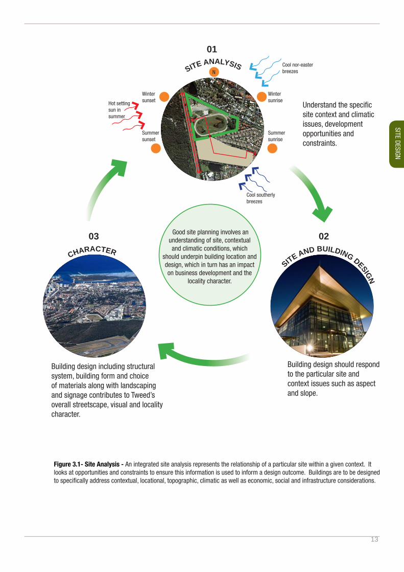
Figure 3.1- Site Analysis - An integrated site analysis represents the relationship of a particular site within a given context. It looks at opportunities and constraints to ensure this information is used to inform a design outcome. Buildings are to be designed to specifically address contextual, locational, topographic, climatic as well as economic, social and infrastructure considerations.
SITE ANALYSIS
Good site planning involves an understanding of site, contextual and climatic conditions, which
should underpin building location and design, which in turn has an impact on business development and the
locality character.
01
Building design should respond to the particular site and context issues such as aspect and slope.
Building design including structural system, building form and choice of materials along with landscaping and signage contributes to Tweed’s overall streetscape, visual and locality character.
SITE AND BUILDING DESIGN
C
HARACTER
Understand the specific site context and climatic issues, development opportunities and constraints.
Cool nor-easterbreezes
Cool southerly breezes
0203
Hot setting sun in summer
N
Wintersunrise
Wintersunset
Summersunset
Summersunrise
14
Objectives
O1. To ensure that the specific opportunities and constraints of the site and its surroundings are comprehensively considered in the development of concepts for the staging and development of the site.
O2. To ensure that the character of the locality is either retained or enhanced.
O3. To ensure that the site is developed in a logical and cost-effective manner.
O4. To ensure that impacts on the adjoining local and regional road network are within the capacity of these networks.
O5. To improve the amenity of the site and adjoining land and to encourage quality built outcomes, maintenance of the landscape setting, and comfortable places for people to work.
O6. To ensure that positioning of a building or structure on the site takes into account the intended use and seeks to minimise potential adverse impacts on the amenity of neighbours and the public.
O7. To ensure that development occurs in an ecologically sustainable manner, and is energy and water efficient in terms of design and layout, resource consumption, and materials.
O8. To ensure that the site is appropriately and effectively serviced by utility services to support the intended development.
Controls
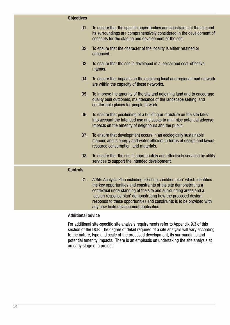
C1. A Site Analysis Plan including ‘existing condition plan’ which identifies the key opportunities and constraints of the site demonstrating a contextual understanding of the site and surrounding areas and a ‘design response plan’ demonstrating how the proposed design responds to these opportunities and constraints is to be provided with any new build development application.
Additional advice
For additional site-specific site analysis requirements refer to Appendix 9.3 of this section of the DCP. The degree of detail required of a site analysis will vary according to the nature, type and scale of the proposed development, its surroundings and potential amenity impacts. There is an emphasis on undertaking the site analysis at an early stage of a project.
15
SITE DESIGN
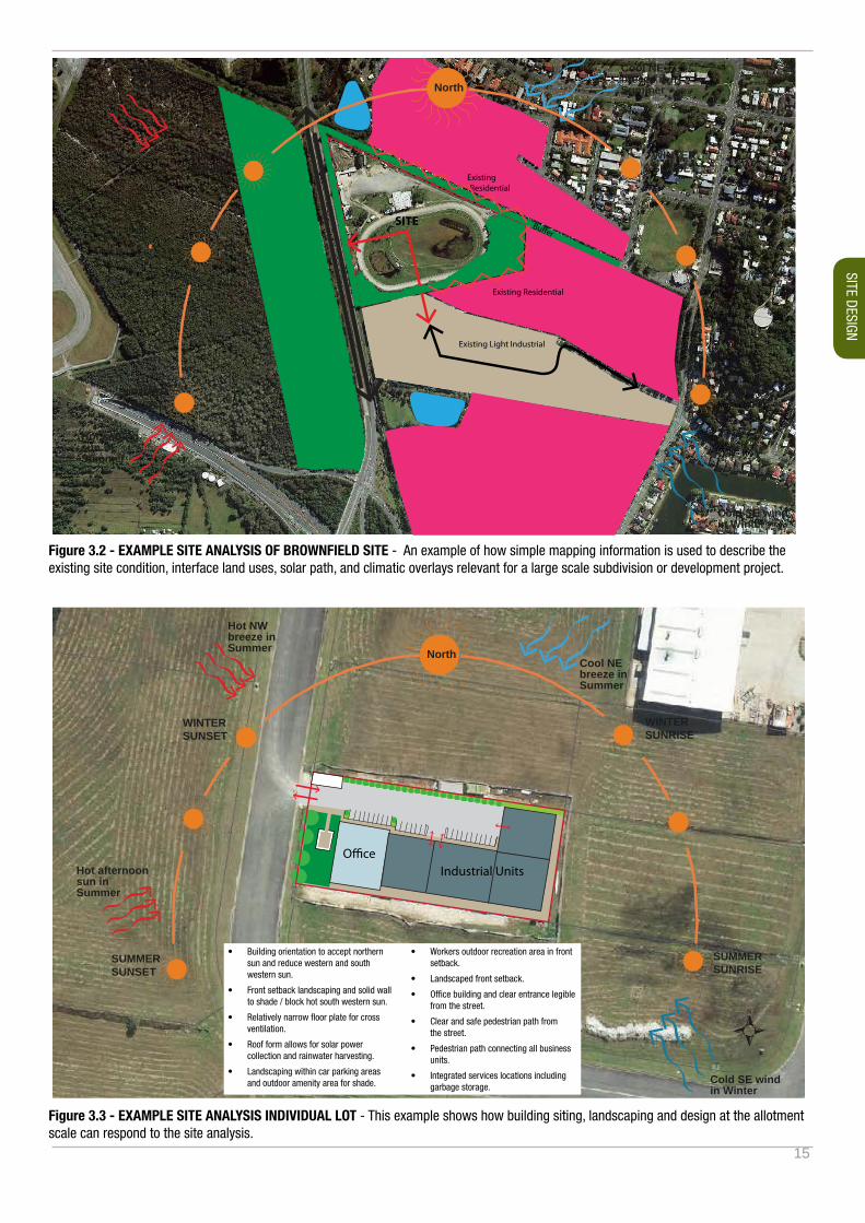
Figure 3.3 - EXAMPLE SITE ANALYSIS INDIVIDUAL LOT - This example shows how building siting, landscaping and design at the allotment scale can respond to the site analysis.
O�ceIndustrial Units
Hot NW breeze in Summer
Hot afternoonsun in Summer
Cool NE breeze in Summer
Cold SE wind in Winter
SUMMERSUNSET
SUMMERSUNRISE
WINTERSUNSET
WINTERSUNRISE
North
• Building orientation to accept northern sun and reduce western and south western sun.
• Front setback landscaping and solid wall to shade / block hot south western sun.
• Relatively narrow floor plate for cross ventilation.
• Roof form allows for solar power collection and rainwater harvesting.
• Landscaping within car parking areas and outdoor amenity area for shade.
• Workers outdoor recreation area in front setback.
• Landscaped front setback.
• Office building and clear entrance legible from the street.
• Clear and safe pedestrian path from the street.
• Pedestrian path connecting all business units.
• Integrated services locations including garbage storage.
Figure 3.2 - EXAMPLE SITE ANALYSIS OF BROWNFIELD SITE - An example of how simple mapping information is used to describe the existing site condition, interface land uses, solar path, and climatic overlays relevant for a large scale subdivision or development project.
Hot NW breeze in Summer
Hot setting sun in Summer
Cool NE breeze in Summer
Existing Light Industrial
Existing Residential
Bu�er
Bu�er
Existing Residential
SITE
Gold Coast Airport
Cold SE wind in Winter
SUMMERSUNSET
SUMMERSUNRISE
WINTERSUNSET
WINTERSUNSET
North

16
3.2. Urban Design
Preamble:
Best practice urban design starts with site planning which involves an understanding of site, contextual and climatic conditions which should then underpin building design location, which in turn adds value to the overall streetscape and locality character.
Embodying best practice urban design principles will generally result in business development sites and individual buildings which, by utilising passive design principles are cheaper to run, have higher amenity for visitors and employees and generally have a better appearance.
Objectives:
O1. To achieve good urban design outcomes by facilitating high quality employment generating land uses that recognise the contextual relationship of the site, and surrounding area by:
- Drawing on best practice urban design principles.
- Providing a sense of place and high quality working environments which include outdoor amenity spaces for employees and other site users.
- To ensure that new development sites or individual lots, and development generally is designed to integrate sustainable design principles.
Controls:
C1. All applications other than alterations and additions, first use or change of use are to submit a Statement of Design Intent and relevant documentation and diagrams to supplement the site analysis. The statement of design intent should address core urban design principles as they relate to the site and business uses including but not limited to:
i. Access, connectivity – Demonstrate legible and safe external and internal access and connectivity for vehicles, service vehicles and pedestrians. This is particularly pertinent in business developments where large vehicles co-exist with regular vehicle movements and pedestrian activity.
ii. Legibility – Demonstrate legibility and way finding to navigate and move through a site with ease and clarity. Designing in a ‘front address’ is just as important within business development as it is within a residential context.
iii. Human scale – Demonstrate an appropriate scale or range of scales of building form, public domain and areas of outdoor amenity. It is important for design to include smaller scale elements in buildings and public domain which are more of a ‘human scale’ to improve usability, legibility and improve the visual quality.
iv. Quality of edges – The spaces where buildings interface with the street are the most public and visually prominent spaces. Define edges, including a balance of active and engaging edges with landscaping and awnings where relevant. Edges also define entrances and accessibility improving navigation and legibility.

17
SITE DESIGN
v. Adaptability and versatility – Consider designing in the ability of a site, use or building to adapt to changing needs over time in terms of use, size, scale, future subdivision and ability to connect into adjoining parcels of land.
vi. Environmental sensitivity and sustainability – Consideration of the inherent environmental features and climatic context of the site combined with an understanding and application of best practice passive and sustainable design measures.
Additional advice:
Applicants are encouraged to engage the services of a qualified architect in the preparation of design concepts, documentation and administration of construction in order to achieve high quality design and detail in construction and best practice in sustainability.
i. Access and connectivity should address pedestrian movement as well as vehicles.
iii. Human scale elements can include the provision of breakout spaces for employees.
v. Adaptability of building design allows for flexibility to expand or carry out a number of different uses over time.
iv. Quality of edges defines the visual character and experiential quality of spaces..
ii. Building legibility defined by architectural elements, colour and light.
vi. Sustainability includes whole of site measures including orientation and integration with natural systems and environmental features of a site as well as building design.
Figure 3.4 - Core Urban Design Principles
18
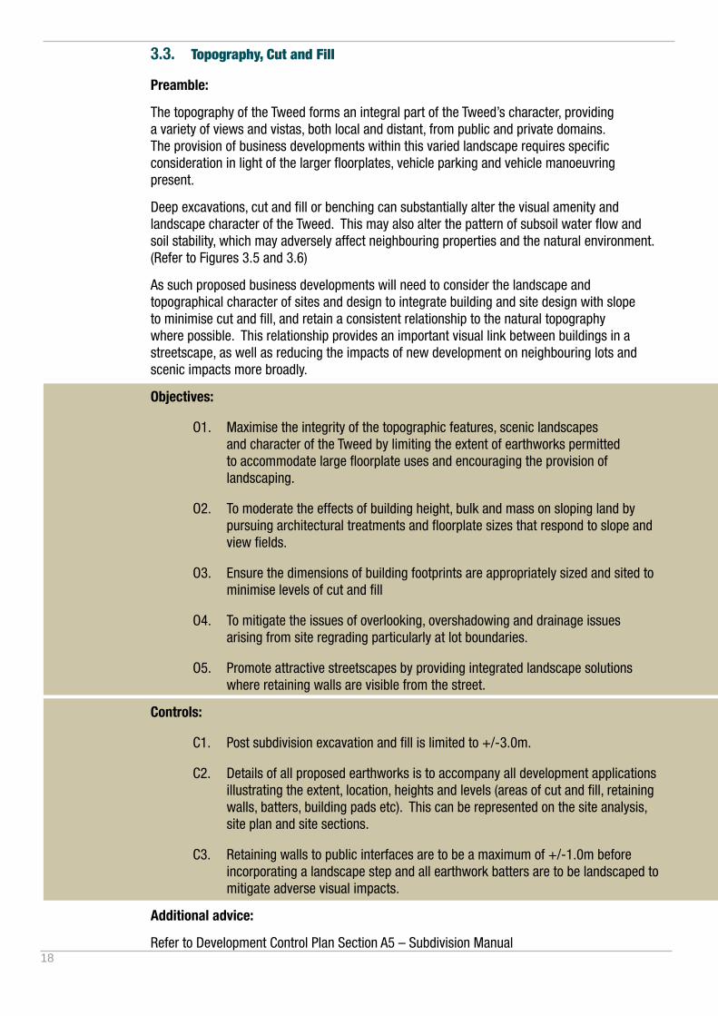
3.3. Topography, Cut and Fill
Preamble:
The topography of the Tweed forms an integral part of the Tweed’s character, providing a variety of views and vistas, both local and distant, from public and private domains. The provision of business developments within this varied landscape requires specific consideration in light of the larger floorplates, vehicle parking and vehicle manoeuvring present.
Deep excavations, cut and fill or benching can substantially alter the visual amenity and landscape character of the Tweed. This may also alter the pattern of subsoil water flow and soil stability, which may adversely affect neighbouring properties and the natural environment. (Refer to Figures 3.5 and 3.6)
As such proposed business developments will need to consider the landscape and topographical character of sites and design to integrate building and site design with slope to minimise cut and fill, and retain a consistent relationship to the natural topography where possible. This relationship provides an important visual link between buildings in a streetscape, as well as reducing the impacts of new development on neighbouring lots and scenic impacts more broadly.
Objectives:
O1. Maximise the integrity of the topographic features, scenic landscapes and character of the Tweed by limiting the extent of earthworks permitted to accommodate large floorplate uses and encouraging the provision of landscaping.
O2. To moderate the effects of building height, bulk and mass on sloping land by pursuing architectural treatments and floorplate sizes that respond to slope and view fields.
O3. Ensure the dimensions of building footprints are appropriately sized and sited to minimise levels of cut and fill
O4. To mitigate the issues of overlooking, overshadowing and drainage issues arising from site regrading particularly at lot boundaries.
O5. Promote attractive streetscapes by providing integrated landscape solutions where retaining walls are visible from the street.
Controls:
C1. Post subdivision excavation and fill is limited to +/-3.0m.
C2. Details of all proposed earthworks is to accompany all development applications illustrating the extent, location, heights and levels (areas of cut and fill, retaining walls, batters, building pads etc). This can be represented on the site analysis, site plan and site sections.
C3. Retaining walls to public interfaces are to be a maximum of +/-1.0m before incorporating a landscape step and all earthwork batters are to be landscaped to mitigate adverse visual impacts.
Additional advice:
Refer to Development Control Plan Section A5 – Subdivision Manual

19
SITE DESIGN
Figure 3.5- Cut and Fill - On sloping sites, building type and use needs to be appropriately suited to the site conditions. Large floorplate development on sloping sites leads to large amounts of earthworks and retaining walls. A series of smaller building footprints will assist in reducing interface retaining wall heights by stepping with the land form.
NATURAL GROUND LEVEL
NATURAL GROUND LEVEL
NATURAL GROUND LEVEL
Smaller separate building footprints on sloping sites led to smaller intrallotment retaining walls and a better streetscape outcome.
Landscaping retaining and batter areas improves the visual appearance.
Large building footprints on sloping sites lead to significant amounts of cut and fill and large intrallotment retaining walls. This can result in a poor street interface outcome which would need to be addressed through landscaping.
FILL
CUT
Smaller building footprints which step with the landscape and take up the level change within the building footprint.
Landscaping front verge and setback areas improves the visual appearance.
Combining landscaping with retaining walls obscure the structural walls and create a more harmonious, visually attractive streetscape interface. Retaining walls are to be a maximum of +/-1.0m before a landscape step is required.
Figure 3.6: Retaining walls- The design and integration of landscaped retaining walls with the streetscape is an important consideration which significantly influences the character and visual quality of a business development.

20
21
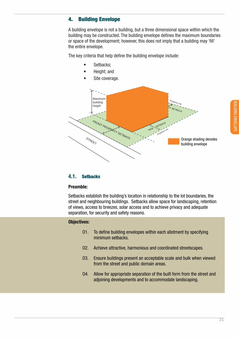
4. Building Envelope
A building envelope is not a building, but a three dimensional space within which the building may be constructed. The building envelope defines the maximum boundaries or space of the development; however, this does not imply that a building may ‘fill’ the entire envelope.
The key criteria that help define the building envelope include:
• Setbacks;• Height; and• Site coverage.
4.1. Setbacks
Preamble:
Setbacks establish the building’s location in relationship to the lot boundaries, the street and neighbouring buildings. Setbacks allow space for landscaping, retention of views, access to breezes, solar access and to achieve privacy and adequate separation, for security and safety reasons.
Objectives:
O1. To define building envelopes within each allotment by specifying minimum setbacks.
O2. Achieve attractive, harmonious and coordinated streetscapes.
O3. Ensure buildings present an acceptable scale and bulk when viewed from the street and public domain areas.
O4. Allow for appropriate separation of the built form from the street and adjoining developments and to accommodate landscaping.
Orange shading denotes building envelope
Maximum building height
Maximum Site CoverageFRONT PROPERTY SETBACKSTREET
REAR PROPERTY SETBACK
SIDE SETBACK
Property Line
Property Line
Property Line
BUILDING ENVELOPE
22
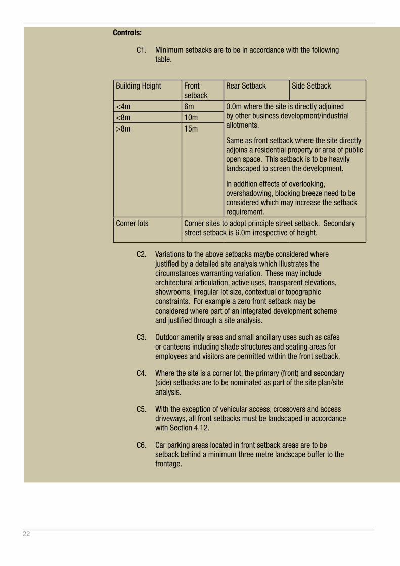
Controls:
C1. Minimum setbacks are to be in accordance with the following table.
Building Height Front
setbackRear Setback Side Setback
<4m 6m 0.0m where the site is directly adjoined by other business development/industrial allotments.
Same as front setback where the site directly adjoins a residential property or area of public open space. This setback is to be heavily landscaped to screen the development.
In addition effects of overlooking, overshadowing, blocking breeze need to be considered which may increase the setback requirement.
<8m 10m>8m 15m
Corner lots Corner sites to adopt principle street setback. Secondary street setback is 6.0m irrespective of height.
C2. Variations to the above setbacks maybe considered where justified by a detailed site analysis which illustrates the circumstances warranting variation. These may include architectural articulation, active uses, transparent elevations, showrooms, irregular lot size, contextual or topographic constraints. For example a zero front setback may be considered where part of an integrated development scheme and justified through a site analysis.
C3. Outdoor amenity areas and small ancillary uses such as cafes or canteens including shade structures and seating areas for employees and visitors are permitted within the front setback.
C4. Where the site is a corner lot, the primary (front) and secondary (side) setbacks are to be nominated as part of the site plan/site analysis.
C5. With the exception of vehicular access, crossovers and access driveways, all front setbacks must be landscaped in accordance with Section 4.12.
C6. Car parking areas located in front setback areas are to be setback behind a minimum three metre landscape buffer to the frontage.

23
BUILDING ENVELOPE
P
10.0m
<8.0m high
6.0m
10.0m
15.0m
P
10.0m
0.0m side setback permitted
SectionFr
ont b
ound
ary
0.0m side setback
0.0m rear/sidesetback permitted within business park zones where site adjoins other business park lots.
0.0m rear/sidesetback permitted within business park zones where site adjoins other business park lots.
6.0m rear/sidesetback required where site adjoins residential or public open space.
>8.0m high15.0m
<4.0m high
4.0-8.0m high
>8.0m high
P
6.0m
<4.0m high
6.0m
Outdoor Area
Outdoor Area
6.0m<4.0m high
Figure 4.1 - Setback Diagrams - Illustrating the relationship between building height and front building setback. Some built forms including employee amenity areas and shade structures are permitted within the front setback.
STREET
STREET
CORNER SITE

24
4.2. Site Coverage and Landscape Area
Preamble:
Site coverage refers to the percentage of a site that may be built upon in relation to the overall lot size and reflects the footprint a building may occupy.
Site coverage may be further defined as impermeable and permeable. Excessive site coverage with hard surfaces can increase the volume of stormwater discharged off-site due to a reduction in the land’s ability to absorb water during storm events.
Objectives:
O1. To ensure a balance between built form and landscape which provides a high level of amenity and landscape character.
O2. To present integrated design solutions which takes into consideration provisions for deep soil planting, shade/solar access and drainage.
O3. To allow for future tree planting.
O4. To facilitate viable and variable commercial floor plates.
Controls:
C1. The maximum site coverage is 70% of the site area.
C2. The minimum landscape area is 10% of the site area. Landscaped areas includes all permeable and semi permeable surfaces outside of the defined site coverage area but does not include hardstand driveways, paths and parking areas. The minimum dimension of a landscaped area needs to be 2.0m.
Additional advice:
Refer to the TLEP for the definition of site coverage.
Figure 4.2 - Site Coverage and Landscaped Area - As a guide, the calculation of site coverage generally does not include access ramps, awnings, eaves, outdoor amenity areas, driveways and paths. Refer to site coverage definition within the Tweed LEP.
P
The blue shaded area denotes the area included as site coverage.
The front setback is included in the landscape calculation.
Interallotment landscaping provides opportunity for an attractive visual buffer between uses contributing to streetscape character.
STREET

25
BUILDING ENVELOPE
4.3. Building Heights
Preamble:
Building height controls assist in managing the bulk and scale of development. Whilst maximum building heights are prescribed within the TLEP, alternative building heights may need to be pursued in order to integrate within existing areas, retain amenity and avoid excessive visual impact.
Of particular relevance is firstly the greater building height often required due to the permissible land uses, secondly the increase in visual bulk by virtue of possessing larger floorplates and thirdly, responding to the increase in visual bulk through landscaping and architectural elements that create and preserve an appropriate human scale.
Whilst building height requires consideration, also of importance is ensuring that land is not sterilised or underdeveloped by pursuing low-scale buildings in areas that possess the ability for buildings of greater significance. In this regard, building design not only needs to consider the needs of the intended use and its visual impact, but also the strategic importance of the site for development, cumulative impacts and the ability to respond to greater development intensity where appropriate.
Objectives:
O1. To ensure that buildings do not adversely affect scenic amenity or character of the locality or Tweed’s scenic landscape.
O2. To ensure land is not underutilised by pursuing low-scale development where greater development potential has been identified.
Controls:
C1. Demonstrate how the height of proposed building/s responds and is appropriate to the role and desired future character of the business development and locality.
C2. Buildings are to be constructed to a height that complements the surrounding built form and landscape character.
C3. Demonstrate, through the provision of landscaping plan, the provision of plantings that assist in creating a human scale and reducing visual bulk, primarily to the streetscape and secondly within the site.
EXISTING GROUND LEVEL (DASHED)
BUILDING HEIGHT LIMIT
Figure 4.3 - Building Height Measurement - Building height is the height of a building at any point of a building and is the vertical distance between the existing ground level and the highest point of the building.

26
5. Building Design
5.1. Designing for the Tweed Climate
The Tweed is located within a sub-tropical climate zone and the main characteristics include:
• High humidity, especially inland areas away from the coast;
• High temperatures year round with mild winters;
• Minimal seasonal temperature variation (average 14-26 oC);
• Low diurnal range (day/night temperature fluctuation); and
• Higher than average rainfall (average 1550mm per annum).
Well considered building design in response to this climatic context has the ability to greatly enhance building amenity and can have a significant impact on the efficiency of business operations, on-going operational costs and the quality of the working environment. Innovation in design and the incorporation of design elements which reduce consumption and operational costs over the life cycle of the building should therefore be a major consideration in the design.
Objectives:
O1. Maximise energy efficiency and passive design measures in all business developments.
Control
C1. Development applications for construction of buildings are to demonstrate integration of the following passive design principles where relevant:
- design to moderate solar access into the building to reduce reliance on artificial lighting and to maximise sun entry during winter months, and maximise sunshading (especially north, western and south western elevations) during summer months;
- design to promote natural cross ventilation and stack ventilation;
- materials chosen for their climatic/diurnal appropriateness (including thermal mass), low toxicity and having low embodied energies in their production;
- A high level of energy efficiency through building design, passive solar design, insulation, minimised reliance on mechanical HVAC (Heating, Ventilation and Air Conditioning), and lighting systems and smart metering;
N
S E
W
Spring / Autumn
Win
ter
N
S E
WSum
mer
COOL SUMMER BREEZES
SOUTHERLY BUSTER DRIVEN WIND AND RAIN
WINTER
WINTER
SUMMER
SUMMER
HOT SUMMER SUN
N
S E
W
Spring / Autumn
Win
ter
N
S E
WSum
mer
COOL SUMMER BREEZES
SOUTHERLY BUSTER DRIVEN WIND AND RAIN
WINTER
WINTER
SUMMER
SUMMER
HOT SUMMER SUN
Cross Ventilation - Design in high level operable windows and narrower floorplates to encourage cross ventilation through a building.
N
S E
W
Spring / Autumn
Win
ter
N
S E
WSum
mer
COOL SUMMER BREEZES
SOUTHERLY BUSTER DRIVEN WIND AND RAIN
WINTER
WINTER
SUMMER
SUMMER
HOT SUMMER SUN
N
S E
W
Spring / Autumn
Win
ter
N
S E
WSum
mer
COOL SUMMER BREEZES
SOUTHERLY BUSTER DRIVEN WIND AND RAIN
WINTER
WINTER
SUMMER
SUMMER
HOT SUMMER SUN
Thermal Mass and Insulation - Cross ventilation, thermal mass and insulation can all work together at different times of the year to maintain a median level of occupant comfort and energy savings.

27
- Collection and reuse of rainwater throughout the building and surrounding landscaping areas;
- A high standard for an energy efficient hot water supply system;
- Reduced non-renewable energy use through efficient heating/cooling systems, water supply systems and electrical appliances;
Additional advice:
Also refer to BASIX, (the Building Sustainability Index, an interactive web-based planning and assessment tool that measures energy and potable water consumption for residential development in NSW and sets minimum requirements for development at www.basix.nsw.gov.au. Refer to the following standards:
• Australian Air Conditioning, Refrigeration, and Heating Industry;
• Water Efficiency Labelling, and
• AAA rated water fittings.
N
S E
W
Spring / Autumn
Win
ter
N
S E
WSum
mer
COOL SUMMER BREEZES
SOUTHERLY BUSTER DRIVEN WIND AND RAIN
WINTER
WINTER
SUMMER
SUMMER
HOT SUMMER SUN
N
S E
W
Spring / Autumn
Win
ter
N
S E
WSum
mer
COOL SUMMER BREEZES
SOUTHERLY BUSTER DRIVEN WIND AND RAIN
WINTER
WINTER
SUMMER
SUMMER
HOT SUMMER SUN
Design to optimise occupant comfort - Simple design measures such as designing an appropriate eave depth can lead to significant energy savings.
N
S E
W
Spring / Autumn
Win
ter
N
S E
WSum
mer
COOL SUMMER BREEZES
SOUTHERLY BUSTER DRIVEN WIND AND RAIN
WINTER
WINTER
SUMMER
SUMMER
HOT SUMMER SUN
Figure 5.1 - Ecological Sustainable Design Measures - The inclusion of water harvesting and water saving measures combined with solar hot water and solar power panels contributes to achieving the best possible green star rating of a building.
BUILDING DESIGN

28
5.2. Building Form and Materials
Preamble:
Building form combined with material and fenestration composition (windows, doors, openings and skylights) influences the bulk, scale, mass and visual appearance which in turn influences streetscape and locality visual amenity. Business and commercial buildings inherently have large floor plate areas and expansive elevations which are typically of a greater height scale and bulk.
Rather than the built form presenting as a large and featureless box or shed, it is important to articulate building elevations and break down the bulk and mass to improve building design and streetscape appeal. (Refer to Figure 5.2, 5.3).
Incorporation of smaller scale built form elements, selection of materials and interesting roof forms can significantly improve not only the visual appearance but also the comfort level and energy efficiency of a building.
Consideration should also be given to the lifecycle of materials, the longevity and maintenance requirements to a given location, particular those sites exposed to the marine environment.
Objectives:
O1. Ensure building form, architectural features, materials and colours are utilised to achieve attractive streetscapes, address other important interface elevations and improve building design.
O2. To encourage finishes and building materials appropriate to the local climatic conditions, solar orientation and site specific features.
O3. To encourage a mix of materials which serve to break down the overall scale, bulk and mass of large buildings.
O4. To encourage building design to present a harmonious coordinated streetscape throughout the development.
O5. To encourage the use of non-toxic and low embodied energy materials that minimise the impact on the environment.
O6. To encourage materials and finishes that are durable, high quality and low maintenance which assist in the thermal comfort and amenity of the building.
Controls:
C1. The siting of business and commercial buildings are to be designed to:
- to ‘face’ or ‘address’ the street frontage(s) in terms of building elevations and articulation;
- encourage pedestrian generating activities such as cafes, canteens and employee amenity areas located towards the public domain, creating visual interest, human scale and informal surveillance to the street;

29
BUILDING DESIGN
- clearly articulate entries to buildings and access pathways and where possible separate and delineate pedestrian and vehicle movement;
- include awnings and or shade structures where development directly fronts a public road, outdoor amenity area or where a pedestrian access route is defined;
- enhance integration and connection between internal and external spaces,
- define and enhance the public domain and be in scale with surrounding buildings,
C2. The design of business and commercial buildings are to:
- use a mix of materials, architectural features and colours which will improve the articulation and overall visual appearance and serve to breakdown the overall building scale, bulk and mass. (Refer to Figure 5.3 for design principles). A schedule of materials and finishes including proposed palette of colours is to be submitted with any development application.
- articulate different three dimensional elements of the building by expressing volumes through form and material mix including stepping, recessing, cantilevering or projecting building form elements.
- breakdown scale and bulk by incorporating architectural detail and human scale elements such as an entrance canopies, foyers and awning.
- using a series of roofs rather than one single roof form to create architectural interest and reduce impacts of reflectivity and glare, and use visually mitigating colours where roofs will be visible or looked down on from surrounding areas.
- provide screens to conceal loading, storage, rubbish disposal, plant, equipment and other similar uses in side and rear areas.

30
Additional controls for Large Floor Plate Development:
C3. Large floor plate developments are to be designed to:
- Activate at least 50% of the building frontage with generous and identifiable building entrance, display windows and human scale built form elements including shade structures, awnings, outdoor amenity spaces, landscaping, BBQ areas, canteens and cafes.
- Limit large expanses of blank or unarticulated elevations to less than 15m in length and 5m in height.
- Incorporate architectural detail and interest at visually prominent building locations such as entrances, lower level front facades, roof tops, on visible corners and at the terminations of street vistas.
- Provide legible dedicated pedestrian access to the building and through car parking areas and street to the frontage allowing for pedestrians moving bulky good items and where possible, enhance pedestrian and cycle networks/linkages to surroundings.
- Not include large format signage or branding across whole elevations including large format images across display windows.
- Minimise the impacts of overlooking, overshadowing, noise and lighting on adjoining landuses, and provide appropriate landscape buffers and visual screening treatments to mitigate impacts. This may included vegetation on raised mounds and/or feature acoustic walls.
- Maintain nominated landscape buffer areas by keeping them free of parking or access roads.
- Avoid large car parking areas fronting primary streets. The preference is for the building to define the street. Where this can not be avoided, an adequate landscape buffer is to be provided between the car park and street frontages.
- Create dedicated car parking spaces for large vehicles and vehicles towing trailers.
- Include all loading and unloading activity within the building and minimise detrimental amenity impacts on residential dwellings and other surrounding land uses. Create dedicated bulky good pick-up areas for customers to receive their bulky goods.
- Provide landscaped car parking areas with adequate areas for water sensitive urban design treatment, infiltration and shade trees.
- Allow for car parking concessions of 30% where bulky goods retail premises are co-located with a range of other business uses especially where visitors are likely to visit a number of different land uses on the same development site or precinct.
Note: Applicants are encouraged to engage the services of a qualified architects and landscape architects in the preparation of designs for large floor plate business developments.
Note: See ‘9.3 Dictionary applying to this Section’ for the definition of Large floor plate developments.
31
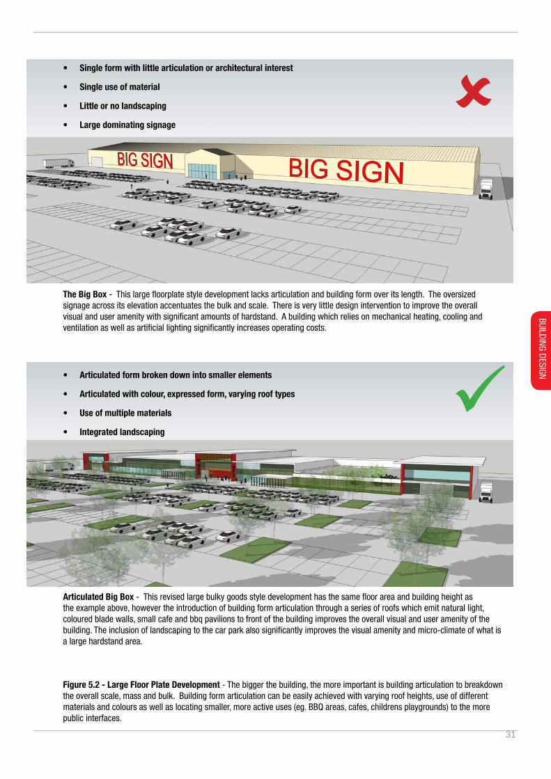
Figure 5.2 - Large Floor Plate Development - The bigger the building, the more important is building articulation to breakdown the overall scale, mass and bulk. Building form articulation can be easily achieved with varying roof heights, use of different materials and colours as well as locating smaller, more active uses (eg. BBQ areas, cafes, childrens playgrounds) to the more public interfaces.
The Big Box - This large floorplate style development lacks articulation and building form over its length. The oversized signage across its elevation accentuates the bulk and scale. There is very little design intervention to improve the overall visual and user amenity with significant amounts of hardstand. A building which relies on mechanical heating, cooling and ventilation as well as artificial lighting significantly increases operating costs.
Articulated Big Box - This revised large bulky goods style development has the same floor area and building height as the example above, however the introduction of building form articulation through a series of roofs which emit natural light, coloured blade walls, small cafe and bbq pavilions to front of the building improves the overall visual and user amenity of the building. The inclusion of landscaping to the car park also significantly improves the visual amenity and micro-climate of what is a large hardstand area.
• Single form with little articulation or architectural interest
• Single use of material
• Little or no landscaping
• Large dominating signage
• Articulated form broken down into smaller elements
• Articulated with colour, expressed form, varying roof types
• Use of multiple materials
• Integrated landscaping
BUILDING DESIGN
32
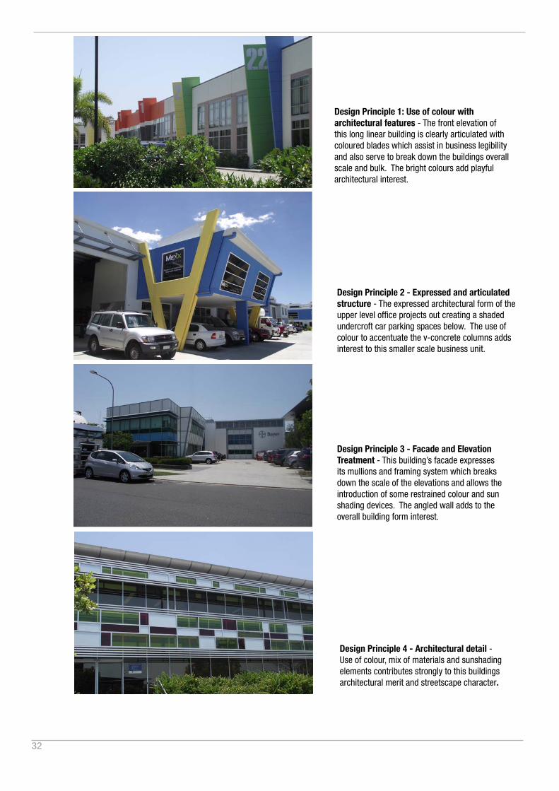
Design Principle 1: Use of colour with architectural features - The front elevation of this long linear building is clearly articulated with coloured blades which assist in business legibility and also serve to break down the buildings overall scale and bulk. The bright colours add playful architectural interest.
Design Principle 2 - Expressed and articulated structure - The expressed architectural form of the upper level office projects out creating a shaded undercroft car parking spaces below. The use of colour to accentuate the v-concrete columns adds interest to this smaller scale business unit.
Design Principle 3 - Facade and Elevation Treatment - This building’s facade expresses its mullions and framing system which breaks down the scale of the elevations and allows the introduction of some restrained colour and sun shading devices. The angled wall adds to the overall building form interest.
Design Principle 4 - Architectural detail - Use of colour, mix of materials and sunshading elements contributes strongly to this buildings architectural merit and streetscape character.
33
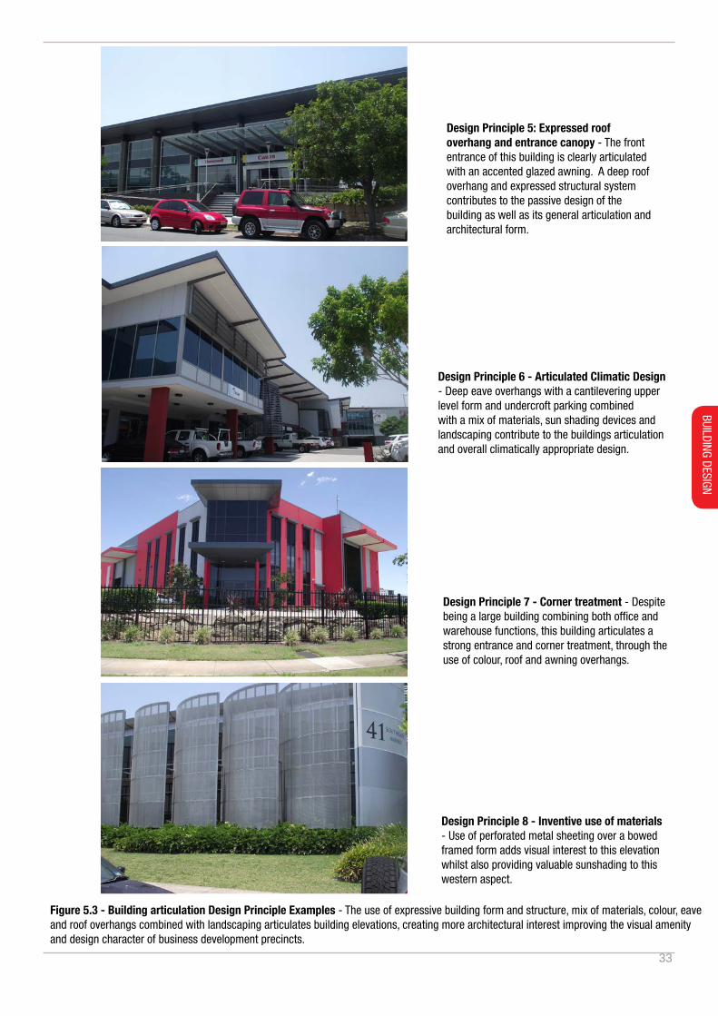
Design Principle 5: Expressed roof overhang and entrance canopy - The front entrance of this building is clearly articulated with an accented glazed awning. A deep roof overhang and expressed structural system contributes to the passive design of the building as well as its general articulation and architectural form.
Design Principle 6 - Articulated Climatic Design - Deep eave overhangs with a cantilevering upper level form and undercroft parking combined with a mix of materials, sun shading devices and landscaping contribute to the buildings articulation and overall climatically appropriate design.
Design Principle 7 - Corner treatment - Despite being a large building combining both office and warehouse functions, this building articulates a strong entrance and corner treatment, through the use of colour, roof and awning overhangs.
Figure 5.3 - Building articulation Design Principle Examples - The use of expressive building form and structure, mix of materials, colour, eave and roof overhangs combined with landscaping articulates building elevations, creating more architectural interest improving the visual amenity and design character of business development precincts.
Design Principle 8 - Inventive use of materials - Use of perforated metal sheeting over a bowed framed form adds visual interest to this elevation whilst also providing valuable sunshading to this western aspect.
BUILDING DESIGN
34
5.3. Overshadowing
Preamble:
It is important when designing business and commercial buildings to consider the impact of overshadowing of a proposed development on adjoining properties, particularly where sites interface with residential land uses. Business and commercial type buildings are typically larger in terms of height and envelope and therefore will cast larger shadows. In some instances, overshadowing may be unavoidable however unreasonable overshadowing of neighbours and outdoor amenity areas as a result of poor design is not acceptable.
Objectives:
O1. To ensure that the overshadowing of neighbouring properties is minimised.
O2. To ensure that reasonable sunlight access to neighbouring properties and outdoor amenity areas are retained.
Controls:
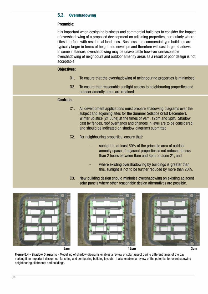
C1. All development applications must prepare shadowing diagrams over the subject and adjoining sites for the Summer Solstice (21st December), Winter Solstice (21 June) at the times of 9am, 12pm and 3pm. Shadow cast by fences, roof overhangs and changes in level are to be considered and should be indicated on shadow diagrams submitted.
C2. For neighbouring properties, ensure that:
- sunlight to at least 50% of the principle area of outdoor amenity space of adjacent properties is not reduced to less than 2 hours between 9am and 3pm on June 21, and
- where existing overshadowing by buildings is greater than this, sunlight is not to be further reduced by more than 20%.
C3. New building design should minimise overshadowing on existing adjacent solar panels where other reasonable design alternatives are possible.
Figure 5.4 - Shadow Diagrams - Modelling of shadow diagrams enables a review of solar aspect during different times of the day making it an important design tool for siting and configuring building layouts. It also enables a review of the potential for overshadowing neighbouring allotments and buildings.
9am 12pm 3pm
35
5.4. Views and Visual Amenity
Preamble:
The wide mountain and river panoramas of the Tweed are an integral part of the Tweed’s character, and highly valued by the community. It is essential that these iconic views and vistas are protected.
Given the diverse nature of land uses within business developments which includes large format buildings and an intensity of traffic and service vehicle movements, there is potential for view and visual amenity impacts both locally and more regionally. This is particularly the case where business development sites are located on exposed sites, adjoin or are visually connected to surrounding residential areas.
It is important to understand the potential visual amenity issues early in the design process, and design to mitigate potentially adverse impacts. This may include screens and landscaping to mitigate overlooking and privacy issues and roof forms and colours chosen to be compatible with the broader landscape character. Landscaping can play an important role in mitigating adverse visual impacts.
The site analysis plan should identify potential for adverse visual impacts on adjoining land and land uses.
Objectives:
O1. To ensure existing public views and vistas particularly those of important natural features such as ridgelines, waterways or bushland are retained and enhanced where practical.
O2. To protect the iconic scenic landscape of the Tweed.
O3. To ensure the provisions of Tweeds scenic landscape studies are considered in building and subdivision design.
O4. To protect the privacy and visual amenity of adjoining landuses.
Controls:
C1. Potential view and overlooking impacts and the design response/s pursued are to be documented within a site analysis.
C2. Where business developments interface with residential or open space areas, visual amenity impacts are to be mitigated against through building design and landscaping. For example, an unarticulated concrete tilt up wall interfacing with a residential area is unacceptable.
C3. Where located within a recognised view corridor a Visual Impact Statement may be required.
C4. The design of roof forms and use of colour is to have regard to and be compatible with the broader landscape character especially when on exposed locations.
BUILDING DESIGN

36
6. Landscaping
Preamble:
Landscaping provides a balancing ‘soft edge’ and green screening to built form. Landscaping also assists in modifying the local climate, providing shade, opportunity to recreate and be incorporated into water sensitive urban design of the site. Protection of existing flora and where possible, integration with any existing or proposed local or regional vegetation corridors should be incorporated into development plans.
Any vegetation to be removed, preserved, enhanced or incorporated into site landscaping should be clearly identified in a landscaping plan and/or site analysis.
Objectives:
O1. To provide quality site landscaping appropriate to the nature and scale of the development.
O2. To enhance the appearance and amenity of development and to integrate with the character, streetscape and locality.
O3. To limit heat impacts from hard surface areas, improve the solar performance of buildings, microclimate conditions of sites, open space and streetscape.
O4. To provide an outdoor area of amenity for employees and visitors for relaxation and recreation.
O5. To promote water sensitive urban design integrated into landscaping by enabling natural infiltration of rainwater and reduction in stormwater runoff.
Controls:
C1. Submit a landscape plan making provision for appropriate landscaping areas, buffers. Any proposed removal of trees or vegetation is to be identified on the landscaping plan.
C2. On individual allotments, the front setback, excluding access ways, is to have a landscape buffer of at least 3.0 metres depth.
C3. Each development shall be provided with at least one private open space area for the use and enjoyment of employees and visitors. The area shall be suitably embellished with shade and seats. Rather than occupying ‘leftover spaces’ these areas should have regard for outlook, sun and shade, and noise. These areas should be nominated on the site analysis or site plan with the size proportionate to proposed floor area and number of staff. As a guide the area should be at least 50sqm.

37
Landscaping individual lots - Landscaping, particularly within the front setback enhances the amenity of the streetscape and provides shade to car parking and outdoor amenity areas.
Outdoor amenity spaces - Well considered outdoor spaces need to be provided for employees to use during breaks. As a minimum, these spaces should include seating and a mix of a permanent shade structure with shade trees.
Within Mitchells Eco-Industrial estate outdoor amenity spaces adjoining a wetland area which also treats and stores the sites stormwater. The wetland is a habitat for birds, fish, crayfish and turtles.
Site Landscaping - A comprehensive whole of site landscape plan defines the character and significantly improves the visual amenity of business precincts.
Figure 6.1 - Business Landscaping - The integration of urban structure and subdivision design with a landscape strategy significantly influences the visual character and amenity of a business development. The implementation of landscaping and ongoing maintenance at different scales and stages of development, including street trees and public domain planting at the subdivision stage, and individual front setback landscaping for each individual building, are key to an effective landscaping strategy.
LANDSCAPING
38
7. Ancillary Buildings, Uses and Structures
Ancillary development comprises land uses and minor development which are ancillary to the main use of a building. Ancillary development may include neighbourhood shops, childcare facilities and minor building works but also may include elements such as outdoor staff areas, decks, car ports and car parking areas, shade structures, fences, satellite dishes, telecommunications equipment. Whilst ancillary and minor in nature and scale, these structures can impact on the visual amenity and the streetscape when poorly located or designed.
7.1. Shops and Factory Outlets
Preamble:
Given the employment generating nature of business developments, consideration should be given to the integration of neighbourhood shops and other community and social infrastructure needs.
Objectives:
O1. Guide the provision of neighbourhood shops which serve the daily convenience needs of the local workforce and community.
O2. To retain the retail primacy of existing retail centres.
Controls:
C1. In order for Council to consider shops and factory outlets, applicants will need to demonstrate that the proposed retailing use falls into either of the following categories:
i. retailing associated with, and ancillary to business development uses on the same land. Such retailing may include activities such as small shops attached to a factory and selling items such as “seconds” of goods produced in that factory or products which are “made to order” in the factory.
ii. individual shops serving the daily convenience needs of the workforce and/or surrounding catchement and inaccordance with Council’s adopted retail principles.
39
7.2. Child Care Centres
Preamble:
The ability of staff employed in business developments to have their children cared for close to their place of employment provides a valuable opportunity to contribute to the well being and job satisfaction of employees.
Child care facilities could be part of a larger primary business or a stand alone centre within a business development. The need for work based childcare will vary with the type of workplace and employment available. Demand for child care will also depend on the existing service provision and unmet demand in the surrounding area.
Objectives:
O1. Guide the provision of child care centres within business, enterprise and industrial zones.
Controls:
C1. Child care centres should be sited on allotments of a suitable size which provide buffering from adjoining developments so as to minimise possible conflicts such as noise, privacy and security.
C2. Adequate noise abatement, site landscaping and fencing must be provided. Where practical with child needs, such landscaping is to be consistent with adjoining developments.
Additional advice:
Refer also to Children (Education and Care Services) Supplementary Provisions Regulation 2004.
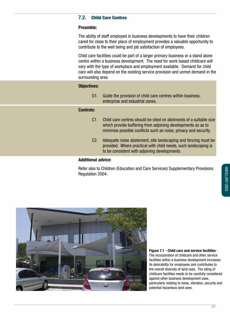
Figure 7.1 - Child care and service facilities - The incorporation of childcare and other service facilities within a business development increases its desirability for employees and contributes to the overall diversity of land uses. The siting of childcare facilities needs to be carefully considered against other business development uses, particularly relating to noise, vibration, security and potential hazardous land uses.
ANCILLARY USES

40
7.3. Signs and Advertising
Preamble:
Well designed integrated signage is an important design element in presenting the image of an integrated business development. Businesses should develop an overall signage strategy for their site incorporating business, directional and temporary signage as an integrated package.
Objectives:
O1. Ensure that signage and associated lighting has been designed and integrated into the overall building design, achieves building legibility but is also restrained as to not detract from streetscape character or dominate the visual amenity of an area.
O2. Ensure that signage design is generally coordinated and consistent in terms of type and size with other businesses within the business development.
Controls:
C1. Maximum of one sign per elevation and tennacy.
C2. Multi-unit developments are to include a single multiple business identification/index sign at the entrance to the site which details each occupant, its activity and unit number to a maximum height of 6 meters and display areas of 15m2. Each individual business signage area within the index sign is to be a maximum of 5m2.
C3. The design and construction of signs are to meet the following requirements:
- Signs are situated near site entries and are well placed for viewing by pedestrians and drivers;
- One free-standing pylon sign per freehold site to a maximum size of 4.0 metres high and 2.5 metres wide;
- Wording on the sign is limited to the name, logo, location, business and products of the establishment;
- Fluorescent or iridescent paints or signs that rotate, flash or move are not supported;
- Signs are to integrate with the form of development scale, colour and style and are not visually dominating.
C4. Directional signage should assist with ‘way finding’ on the site for pedestrians, vehicles and cyclists, including entry and exits, parking controls and delivery and reception areas. Directional signage should be part of an overall signage ‘language’ of fonts, colours and other related imagery for the site.
C5. No bunting, sandwich boards or any ‘stand alone’ advertising structure, except pylon signs detailed above.
Additional advice:
Signage is to be consistent with the additional provisions of DCP A4 – Advertising Signs Code and State Environmental Planning Policy No. 64 - Advertising and Signage.
41
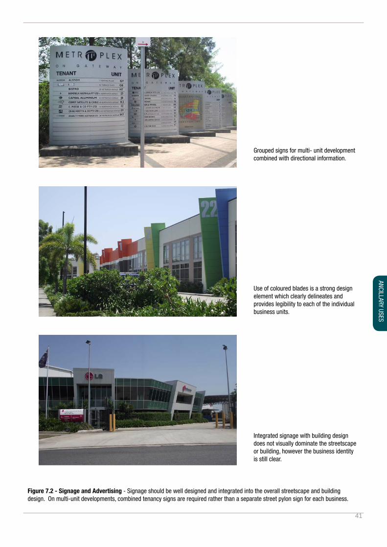
Figure 7.2 - Signage and Advertising - Signage should be well designed and integrated into the overall streetscape and building design. On multi-unit developments, combined tenancy signs are required rather than a separate street pylon sign for each business.
Grouped signs for multi- unit development combined with directional information.
Integrated signage with building design does not visually dominate the streetscape or building, however the business identity is still clear.
Use of coloured blades is a strong design element which clearly delineates and provides legibility to each of the individual business units.
ANCILLARY USES

42
7.4. Fences
Preamble:
Fences and walls include all built vertical landscaping elements designed to define boundaries between one space and the next or to accommodate a change in level. The design of fences and walls has an impact on the real and perceived safety and security of a property as well as on the amenity of the public domain and the streetscape character. The visual impact, scale and design of fences need to be carefully considered as part of an integrated landscape design.
Objectives:
O1. To delineate the boundaries between public and private land and between neighbouring properties with a combination of landscaping and fencing where required.
O2. To minimise the visual impact of fences and allow private landscaping to integrate with the streetscape appearance and maintain visual permeability across sites to (and from) the street.
O3. To offer acoustic and visual privacy on busy roads and mitigate against amenity impacts where business developments adjoin public open space or residential areas.
Controls:
C1. If a front fence is required for security purposes it should be setback behind the 3.0 metres landscaping buffer to a maximum height of 1.8 metres with a maximum solid fence height of 600mm. Above the solid wall the fence is to have a minimum openness ratio of 60%.
C2. The design of the front and return fence shall be integrated with the design of the building, visually permeable and unobtrusive with a mix of materials and/or integrated with landscape design. Unfinished galvanised chain link fencing to the front is not acceptable.
C3. Side and rear fences behind the front setback may be built to a height of 2.1 metres.
C4. Fencing should be sited so that it does not impede sightlines for drivers.
P
Front fence to a max of 1.8m setback behind 3.0m landscape buffer.
Use landscaping to denote property boundary.
Zero setback used as a property boundary.
Maintain adequate sight lines for vehicles entering and leaving the site.
Side and rear fences to a maximum height of 2.1m.
Figure 7.3 - Fencing
STREET
Return

43
7.5. Temporary Outdoor Business Activities
Preamble:
Outdoor business activities may include but are not limited to temporary events such as fundraising barbeques and special promotional events.
Objectives:
O1. To make provision for hosting temporary outdoor business activities.
O2. Ensure that outdoor business activities do not conflict with pedestrian and vehicle movements.
O3. To ensure that temporary outdoor business activities do not adversely impact amenity of adjoining businesses, residential or public open space.
Controls:
C1. The area allocated for the activity must be nominated on a site plan to ensure that any potential conflicts with movement and circulation or any other potential amenity impacts are considered and addressed.
ANCILLARY USES

44
7.6. Safety and Security
Preamble:
Due to the diverse nature of development types possible within a business development, the need may arise for enhanced security and safety provision. While passive supervision of open space, with minimal fencing and landscaping has been the hallmark of ensuring a safe workplace and surroundings, the need for added security measures, for the protection of property, or for minimisation of risk of criminal activity must be considered.
Objectives:
O1. To ensure that development mitigates opportunities for crime and perceived opportunities for crime, without adversely impacting visual amenity of the site or business development.
Controls:
C1. Developments must ensure that the following Crime Prevention Through Environmental Design (CPTED) principles have informed the design of the proposed development:
- Surveillance – Developments should be designed and managed to maximise the potential for passive surveillance;
- Access Control – Developments must be designed in order to make them legible for users without losing the capacity for variety and interest;
- Territorial Reinforcement – Developments must be designed to define clearly legitimate boundaries between private, semi private, and public space, and
- Space Management – Developments must be designed and detailed to minimise damage, and the need for undue maintenance, without undermining the aesthetic and functional qualities of the building.
C2. A Crime Risk Assessment must be prepared and submitted to Council. The Crime Risk Assessment must be prepared by a suitably qualified person and should:
- Analyse the types of crime that may be prevalent in the area, and to which the development may be susceptible,
- Provide information as to how the design was informed by the CPTED principles, and
- Inform the design, construction, or future management practises of the development (e.g. building materials, signage, lighting, landscaping, security patrols, maintenances, and graffiti removal practices).
C3. Any recommendations or shortfalls identified by a Crime Risk Assessment are to be implemented into the design of the development to the satisfaction of the assessing officer.
Additional advice:
Refer to Council’s Crime Prevention Action Plan 2008.
45
PART 2 - SITE SPECIFIC
PART 2 - SITE SPECIFIC PROVISIONS
8. Site Specific Development Controls

46
Figure 8.1.1 - Boyds Bay Business Park Site

47
8.1. Boyds Bay Business Park
The Boyds Bay Business Park (the site), as identified in Figure 8.1, is a 5.15ha land parcel located at Tweed Heads West. The site is immediately bordered by Sugarwood Drive, Parkes Drive and the Pacific Highway to the North and East, the Tweed Heads West Waste Water Treatment Plant and Depot to the West and a holiday village and low density residential development to the South. Analysis of the site to-date indicates no significant native flora and fauna habitat or contribution towards a habitat corridor, threatened species or ecological communities are present. In addition, no watercourses, wetlands and riparian lands of significance have been identified on the site.
Whilst the site is located within a wider general residential context, it is also within one kilometre of the southern extent of the Gold Coast Airport, has strong transport linkages to the Pacific Motorway, and has opportunities to service a portion of the southern Gold Coast population catchment. These attributes present a unique suite of opportunities and constraints.
In light of the land area, site constraints, location of the site to major traffic infrastructure and dislocation from other employment generating land uses, a typical business park scale or land use mix is not anticipated. In this regard, the site is suitable for a small mixed use business park, centred around an anchor use, such as bulky goods retail, hardware and building supplies or showroom uses.
Whilst the dominant use of the site is likely to be a large floor plate use, the remainder of the site should maximise its opportunities and harness the spin-offs of such anchor uses, further generating a specific character and identity (i.e. Homemaker Centre, Market Place etc). In order to provide a variety of tenancy opportunities, complementary gross floor area should be flexible and varied in size, however designed on the basis of further bulky goods retailing, shop and office use.
The built form and land use mix should aim to work together to ensure that development is coordinated and operates as a destination site. A ‘whole of site’ design should result in optimal utilisation of infrastructure including co-located car parking, access and traffic movement, landscaping, stormwater treatment which maximises convenience to the public and minimises adverse impacts both on-site and for the adjoining land. A considered ‘whole of site’ design will also be critical in order to mitigate identified constraints of the site, including potential contamination, building height and material restrictions relating to the Gold Coast Airport operations, flooding, road upgrades and traffic capacity.
Aims of Boyds Bay Business Park
A1. Support an integrated design approach that establishes a variety of complementary business park land uses which respond to site constraints with a quality urban and building design within a business park setting.
Objectives
O1. To establish an integrated, whole of site, business park with high levels of amenity for its users;
O2. Ensure opportunities for a variety of land uses, tenancy types and sizes;
O3. Encourage land uses that maximise employment generation and the strategic proximity of the Gold Coast Airport and Pacific Highway;
O4. To ensure that development responds to the Gold Coast Airport operational requirements (i.e. ANEF, and OLS (Obstacle Limitation Surface) requirements);
PART 2 - SITE SPECIFIC
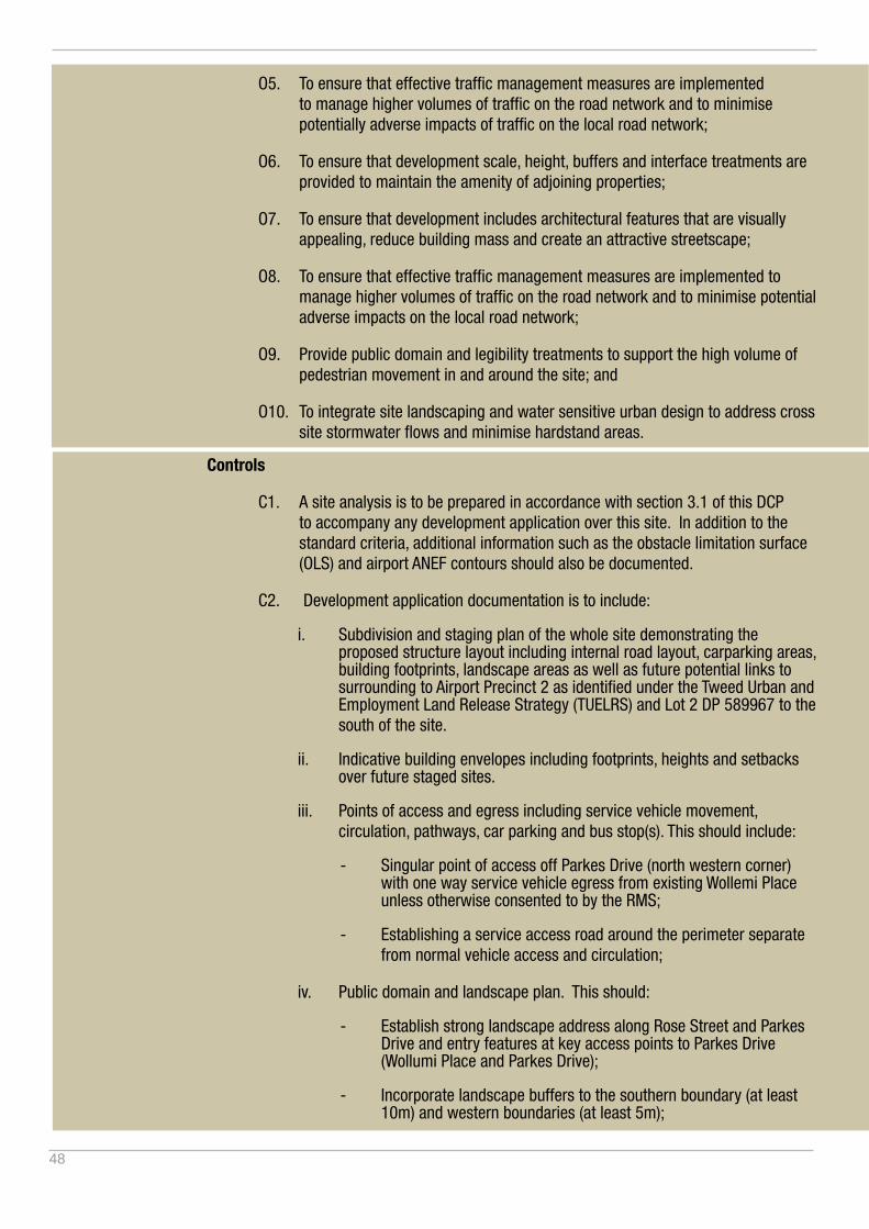
48
O5. To ensure that effective traffic management measures are implemented to manage higher volumes of traffic on the road network and to minimise potentially adverse impacts of traffic on the local road network;
O6. To ensure that development scale, height, buffers and interface treatments are provided to maintain the amenity of adjoining properties;
O7. To ensure that development includes architectural features that are visually appealing, reduce building mass and create an attractive streetscape;
O8. To ensure that effective traffic management measures are implemented to manage higher volumes of traffic on the road network and to minimise potential adverse impacts on the local road network;
O9. Provide public domain and legibility treatments to support the high volume of pedestrian movement in and around the site; and
O10. To integrate site landscaping and water sensitive urban design to address cross site stormwater flows and minimise hardstand areas.
Controls
C1. A site analysis is to be prepared in accordance with section 3.1 of this DCP to accompany any development application over this site. In addition to the standard criteria, additional information such as the obstacle limitation surface (OLS) and airport ANEF contours should also be documented.
C2. Development application documentation is to include:
i. Subdivision and staging plan of the whole site demonstrating the proposed structure layout including internal road layout, carparking areas, building footprints, landscape areas as well as future potential links to surrounding to Airport Precinct 2 as identified under the Tweed Urban and Employment Land Release Strategy (TUELRS) and Lot 2 DP 589967 to the south of the site.
ii. Indicative building envelopes including footprints, heights and setbacks over future staged sites.
iii. Points of access and egress including service vehicle movement, circulation, pathways, car parking and bus stop(s). This should include:
- Singular point of access off Parkes Drive (north western corner) with one way service vehicle egress from existing Wollemi Place unless otherwise consented to by the RMS;
- Establishing a service access road around the perimeter separate from normal vehicle access and circulation;
iv. Public domain and landscape plan. This should:
- Establish strong landscape address along Rose Street and Parkes Drive and entry features at key access points to Parkes Drive (Wollumi Place and Parkes Drive);
- Incorporate landscape buffers to the southern boundary (at least 10m) and western boundaries (at least 5m);

49
- Incorporate street trees lining internal access roads and integrated within car park design for shade and visual amenity;
- Incorporate a pedestrian network connecting buildings, car parking areas and key outdoor amenity areas;
- Incorporate pedestrian pathways within the car parking areas to enable safe movement of pedestrians with trolleys and bulky goods between the stores and car park;
- Incorporate water sensitive urban design treatments to the car parking areas to assist with stormwater infiltration and offset the large amounts of hardstand across the site;
- Creating an open space or public amenity area for employees and visitors alike. This space should be appropriately embellished with landscaping, shade structures, BBQ, seats, tables, water, lighting, electrical supply.
C5. Large floor plate development to incorporate appropriate roof form (which may include varying roof heights) and building form articulation to reduce the amenity impacts such as overshadowing to the south and to result in a higher quality built form outcome.
C6. Incorporate public domain area and smaller scale built form elements to main (front) elevation of large floor plate store (cafe, BBQ stand, child minding space etc);
C7. Only two pylon signs to a maximum of 12m high across the site, and one multi- business sign at the main entrance to the site. Large scale branding or signage along the buildings elevations is not permitted. The use of the existing outdoor cinema screen is not to be used for signage or advertising.
C8. Any application for development over the site must be accompanied by a traffic study demonstrating the ability for the proposal to be accommodated by existing and or proposed road works to the satisfaction of Council and RMS.
C9. Car parking rates can be reduced by 30% where it can be justified that a number of different business park uses in successive stages of the whole of site development can co-locate or share car parking spaces between users / visitors.
Additional Advice:
Refer to other relevant Shire Wide Controls within this plan.
It is recommended that the site analysis be completed and presented as part of draft concept plans at any per DA meeting.
PART 2 - SITE SPECIFIC

50
*
*
SERVICE ONLY
SERV
ICE
ON
LY
LB
LB
LB
LB
LB
IND
ICAT
IVE
LA
RG
E F
LOO
R
PLA
TE B
UIL
DIN
G E
NV
ELO
PE
IND
ICAT
IVE
MU
LTI-U
NIT
B
UIL
DIN
G E
NV
ELO
PE
IND
ICAT
IVE
NA
RR
OW
FLO
OR
P
LATE
BU
ILD
ING
EN
VE
LOP
E
LEG
EN
D
14 0
00sq
m
3850
sqm
(7 te
nanc
ies)
3600
sqm
(2 le
vels
)
394
spac
es
IND
ICAT
IVE
SC
HE
DU
LE
PU
BLI
C D
OM
AIN
/ P
ED
ES
TRIA
N
CIR
CU
LATI
ON
STR
EE
T TR
EE
S
LAN
DS
CA
PE
/ IN
FILT
RAT
ION
A
RE
A
10m
BU
FFE
R T
O R
ES
IDE
NTI
AL
5m B
UFF
ER
TO
WA
STE
WAT
ER
VE
HIC
ULA
R A
CC
ES
S
SE
RV
ICE
VE
HIC
LE A
CC
ES
S
PO
TEN
TIA
L P
YLO
N S
IGN
LO
CAT
ION
IND
ICAT
IVE
RO
UN
DA
BO
UT
LOC
ATIO
N
IND
ICAT
IVE
INTE
RN
AL
RO
AD
IND
ICAT
IVE
CA
R P
AR
K
*
n
PACIFIC HIGHWAY
ROSE STREET
PARK
ES D
RIVE
WOLL
EMI P
L
Inco
rpor
ate
new
traf
fic m
anag
emen
t w
orks
to c
ater
for i
ncre
ased
traf
fic
mov
emen
ts.
Des
ign
in la
ndsc
ape
and
publ
ic
dom
ain
amen
ity fo
r em
ploy
ees
and
visi
tors
.
Con
side
r saf
e pe
dest
rian
mov
emen
ts
of b
ulky
goo
ds a
nd m
ater
ials
bet
wee
n st
ore
and
car p
arki
ng a
reas
. In
clud
e la
ndsc
ape
and
trolle
y pa
rkin
g ba
ys
with
in c
arpa
rk d
esig
n.
Cle
ar a
nd le
gibl
e in
tern
al c
ircul
atio
n w
ith
the
mai
n ax
is d
efin
ed b
y a
stro
ng a
venu
e of
stre
et tr
ees
inco
rpor
ated
into
car
par
k de
sign
.
Hig
hly
visi
ble
elev
atio
n w
hich
will
requ
ire a
hi
gher
leve
l of a
rchi
tect
ural
arti
cula
tion
Land
scap
e bu
ffer t
o R
ose
Stre
et.
Inco
rpor
ate
onsi
te in
filtra
tion
oppo
rtuni
ties.
Inve
stig
ate
pote
ntia
l for
add
ition
al p
oint
of
entry
for n
orth
bou
nd tr
affic
alo
ng R
ose
Stre
et fr
om e
xist
ing
poin
t of e
ntry
.
Pot
entia
l loc
atio
n fo
r pyl
on s
ign.
Pot
entia
l loc
atio
n fo
r pyl
on s
ign.
Inco
rpor
ate
perim
eter
road
to
acco
mm
odat
e se
rvic
e ve
hicl
es.
Allo
w fo
r a ra
nge
of d
iffer
ent f
loor
pl
ate
size
s an
d su
bdiv
isio
n op
portu
nity
to fa
cilit
ate
a ra
nge
of
busi
ness
par
k us
es.
Inco
rpor
ate
publ
ic d
omai
n co
mpo
nent
into
sm
alle
r sca
le fo
rmat
.
Larg
e flo
or p
late
use
to in
corp
orat
e va
ryin
g ro
of h
eigh
t and
bui
ldin
g fo
rm
artic
ulat
ion
to re
duce
the
amen
ity
impa
cts
to th
e so
uth
and
to re
sult
in a
hi
gher
qua
lity
built
form
out
com
e.
Inco
rpor
ate
publ
ic d
omai
n ar
ea a
nd
smal
ler s
cale
bui
lt fo
rm e
lem
ents
to
mai
n el
evat
ion
(caf
e, B
BQ
sta
nd e
tc).
Prim
ary
site
acc
ess
off P
arke
s D
rive.
Inc
orpo
rate
on
site
traf
fic
man
agem
ent t
o se
para
te s
ervi
ce
and
cust
omer
traf
fic m
ovem
ents
.
Opp
ortu
nity
to in
corp
orat
e na
rrow
flo
or p
late
two
stor
ey b
uild
ing
alon
g no
rther
n pe
rimet
er if
ov
erla
nd fl
ow a
nd fl
ood
issu
es a
re
reso
lved
.
Inco
rpor
ate
5.0m
land
scap
e bu
ffer
to th
e Tw
eed
Was
te W
ater
Fa
cilit
y.
Inco
rpor
ate
10m
land
scap
ed
buffe
r to
exis
ting
resi
dent
ial l
and
uses
to th
e so
uth
of th
e si
te.
Bui
ldin
g is
requ
ired
to b
e be
low
th
e O
LS h
eigh
t res
trict
ion.
10m
BU
FFER
TO
RES
IDEN
TIAL
5m BUFFER TO WASTE WATER
Figure 8.1.2 - Boyds Bay Business Park Indicative Configuration - This diagram presents only one configuration which builds on the sites opportunities and constraints to establish a small mixed use business park with a variety of floor plate sizes and co-located car parking and public domain amenity areas.
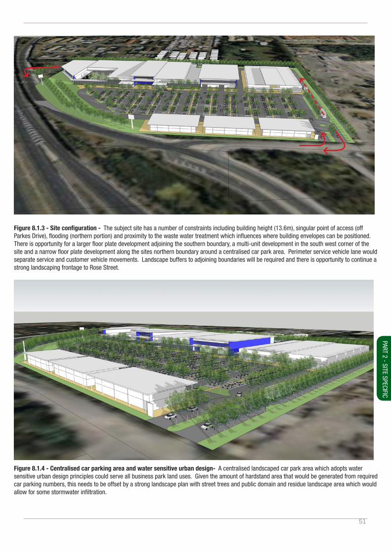
51
Figure 8.1.3 - Site configuration - The subject site has a number of constraints including building height (13.6m), singular point of access (off Parkes Drive), flooding (northern portion) and proximity to the waste water treatment which influences where building envelopes can be positioned. There is opportunity for a larger floor plate development adjoining the southern boundary, a multi-unit development in the south west corner of the site and a narrow floor plate development along the sites northern boundary around a centralised car park area. Perimeter service vehicle lane would separate service and customer vehicle movements. Landscape buffers to adjoining boundaries will be required and there is opportunity to continue a strong landscaping frontage to Rose Street.
Figure 8.1.4 - Centralised car parking area and water sensitive urban design- A centralised landscaped car park area which adopts water sensitive urban design principles could serve all business park land uses. Given the amount of hardstand area that would be generated from required car parking numbers, this needs to be offset by a strong landscape plan with street trees and public domain and residue landscape area which would allow for some stormwater infiltration.
PART 2 - SITE SPECIFIC
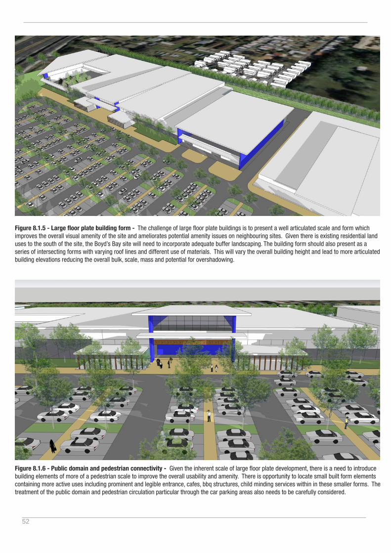
52
Figure 8.1.5 - Large floor plate building form - The challenge of large floor plate buildings is to present a well articulated scale and form which improves the overall visual amenity of the site and ameliorates potential amenity issues on neighbouring sites. Given there is existing residential land uses to the south of the site, the Boyd’s Bay site will need to incorporate adequate buffer landscaping. The building form should also present as a series of intersecting forms with varying roof lines and different use of materials. This will vary the overall building height and lead to more articulated building elevations reducing the overall bulk, scale, mass and potential for overshadowing.
Figure 8.1.6 - Public domain and pedestrian connectivity - Given the inherent scale of large floor plate development, there is a need to introduce building elements of more of a pedestrian scale to improve the overall usability and amenity. There is opportunity to locate small built form elements containing more active uses including prominent and legible entrance, cafes, bbq structures, child minding services within in these smaller forms. The treatment of the public domain and pedestrian circulation particular through the car parking areas also needs to be carefully considered.
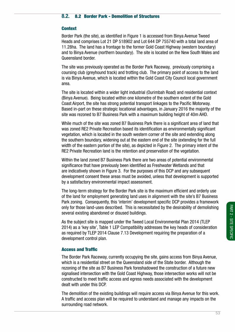
53
8.2. 8.2 Border Park - Demolition of Structures
Context
Border Park (the site), as identified in Figure 1 is accessed from Binya Avenue Tweed Heads and comprises Lot 21 DP 518902 and Lot 644 DP 755740 with a total land area of 11.28ha. The land has a frontage to the former Gold Coast Highway (western boundary) and to Binya Avenue (northern boundary). The site is located on the New South Wales and Queensland border.
The site was previously operated as the Border Park Raceway, previously comprising a coursing club (greyhound track) and trotting club. The primary point of access to the land is via Binya Avenue, which is located within the Gold Coast City Council local government area.
The site is located within a wider light industrial (Ourimbah Road) and residential context (Binya Avenue). Being located within one kilometre of the southern extent of the Gold Coast Airport, the site has strong potential transport linkages to the Pacific Motorway. Based in-part on these strategic locational advantages, in January 2016 the majority of the site was rezoned to B7 Business Park with a maximum building height of 40m AHD.
While much of the site was zoned B7 Business Park there is a significant area of land that was zoned RE2 Private Recreation based its identification as environmentally significant vegetation, which is located in the south western corner of the site and extending along the southern boundary, widening out at the eastern end of the site (extending for the full width of the eastern portion of the site), as depicted in Figure 2. The primary intent of the RE2 Private Recreation land is the retention and preservation of the vegetation.
Within the land zoned B7 Business Park there are two areas of potential environmental significance that have previously been identified as Freshwater Wetlands and that are indicatively shown in Figure 3. For the purposes of this DCP and any subsequent development consent these areas must be avoided, unless that development is supported by a satisfactory environmental impact assessment.
The long-term strategy for the Border Park site is the maximum efficient and orderly use of the land for employment generating land uses in alignment with the site’s B7 Business Park zoning. Consequently, this ‘interim’ development specific DCP provides a framework only for those land-uses described. This is necessitated by the desirability of demolishing several existing abandoned or disused buildings.
As the subject site is mapped under the Tweed Local Environmental Plan 2014 (TLEP 2014) as a ‘key site’, Table 1 LEP Compatibility addresses the key heads of consideration as required by TLEP 2014 Clause 7.13 Development requiring the preparation of a development control plan.
Access and Traffic
The Border Park Raceway, currently occupying the site, gains access from Binya Avenue, which is a residential street on the Queensland side of the State border. Although the rezoning of the site as B7 Business Park foreshadowed the construction of a future new signalised intersection with the Gold Coast Highway, those intersection works will not be constructed to meet traffic access and egress needs associated with the development dealt with under this DCP.
The demolition of the existing buildings will require access via Binya Avenue for this work. A traffic and access plan will be required to understand and manage any impacts on the surrounding road network.
PART 2 - SITE SPECIFIC
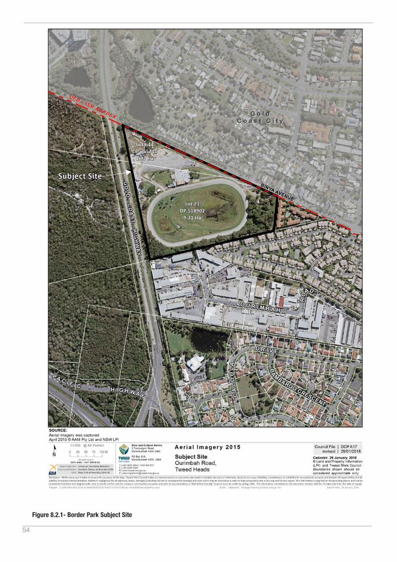
54
Figure 8.2.1- Border Park Subject Site
55
Purpose
The purpose of this section is to satisfy Clause 7.13 of Tweed Local Environmental Plan 2014 pertaining to the requirement for the preparation of a ‘site-specific’ development control plan so as to enliven the consent authority’s power to grant development consent, where appropriate, but only to the extent of the development and use of the land described herein.
Any other development of the land requiring development consent will necessitate the preparation of a further development control plan and for significant redevelopment of the land the preparation of a master-plan in combination with a development control plan.
Application
This section of the development control plan is intended as an interim guideline pertaining to demolition of existing buildings on the subject lands.
This section is scheduled to be repealed 12 months from the date of its making unless earlier repealed by the making of a comprehensive site redevelopment development control plan.
Aims
A1. The aim of this section is to provide a development control plan framework to satisfy the requirements of Clause 7.13 of Tweed Local Environmental Plan 2014 to enliven the consent authority’s powers to grant consent to development (if appropriate) of the kind described herein only.
Objectives
O1. To ensure that effective site planning and traffic management measures are implemented to manage and minimise potentially adverse impacts of traffic on the local road network.
O2. To ensure the protection of identified lands of environmental significance across the site are protected, maintained and managed.
Controls
C1. Environmental management plan detailing how any environmentally sensitive land will be avoided or managed, and which must have regard to the approximate 10m buffer as shown in Figure 3.
C2. An application for development being demolition must include a Demolition Work Plan in accordance with Council’s Development Application Guidelines.
C3. A traffic plan demonstrating the ability for the proposal to manage and/or mitigate potential impacts on the existing road network to the satisfaction of Council.
Additional Advice:
Given the subject site is located on the border between NSW and QLD any future development application will require consultation and coordination with Gold Coast City Council.
Refer to other relevant shirewide controls within this plan.
PART 2 - SITE SPECIFIC

56
Tweed LEP 2014 Clause 7.13 DCP Requirements DCP Consideration
(a) design principles drawn from an analysis of the site and its context,
As an interim and development specific DCP the full range of ultimate design principles is not required and those detailed herein relate the development being ‘demolition’. Design principles will be considered as part of future development planning.
(b) phasing of development, As an interim and development specific DCP the phasing of development is not necessitated. A further comprehensive DCP for the redevelopment of the site will address development phasing.
(c) distribution of land uses, including open space, As an interim and development specific DCP the ultimate distribution of land use is not necessitated. The demolition of existing buildings is likely to occur within existing disturbed areas of the land and on a short-term (temporary) basis, as such the DCP address the considerations for a related development application and use of the land.
(d) subdivision pattern and provision of services, As an interim and development specific DCP land subdivision is not contemplated and will need to be addressed in a future comprehensive redevelopment DCP. The site currently has access to water, sewer, electrical and telecommunication services, however, the these do not need to be addressed for the demolition works.
(e) building envelopes and built form controls, No new buildings are associated with the proposed use of the site enabling the demolition of the existing buildings.
(f) impact on, and improvements to, the public domain, The DCP requires a demolition work plan. There is no proposed future development.
(g) identification and conservation of native flora and fauna habitat and habitat corridors on the site, including any threatened species, populations or ecological com-munities,
Measures are incorporated to ensure the identification, avoidance and protection of environmentally sensitive or significant areas.
(h) identification, extent and management of water-courses, wetlands and riparian lands and any buffer areas,
Measures are incorporated to ensure the identification, avoidance and protection of watercourses, wetlands and riparian lands and any buffer areas.
(i) environmental constraints, including climate change, acid sulfate soils, flooding, contamination and remedia-tion
Council’s mapping indicates that the site is partially flood affected, is identified as being affected by acid sulphate soils and is bushfire prone. These constraints will be considered as part of future development planning.
Table 8.2.1 - Border Park LEP and DCP Compatibility - This table identifies the key heads of consideration identified within Tweed Local Environmental Plan 2014 Clause 7.13 Development requiring the preparation of a development control plan.
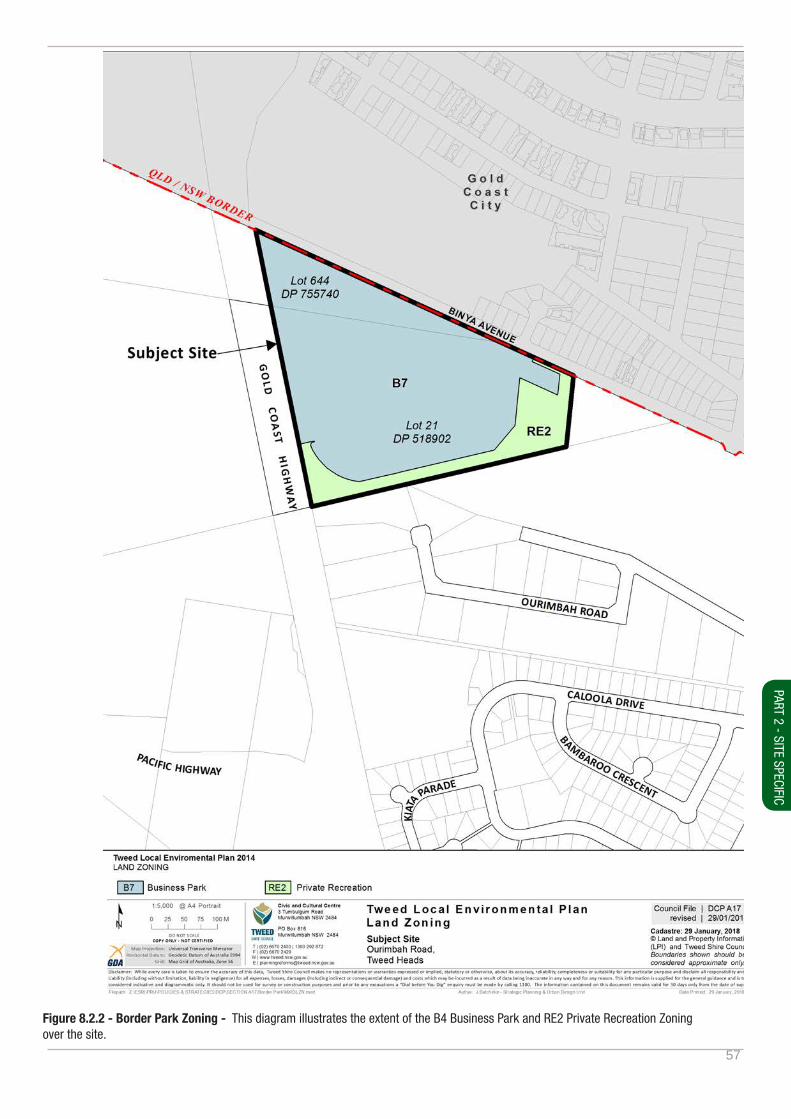
57
Figure 8.2.2 - Border Park Zoning - This diagram illustrates the extent of the B4 Business Park and RE2 Private Recreation Zoning over the site.
PART 2 - SITE SPECIFIC

58
Figure 8.2.3 - Border Park Site Planning Constraints
59
9. Appendices
APPENDICES

60
9.1. Development application submission requirements
The following table provides the development application submission requirements for all business development development types.
Material to be submitted by the applicant at DA stage New Building Building alterations and additions or change of use.
Pre DA Meeting ✓Concept Plan - Scale of 1:100 or 1:200
Submission of a concept plan showing:
Sufficient information for the Development Assessment Panel (DAP) to provide meaningful assessment and feedback
✓
Completed DAP details form ✓Development Application
Site Plan 1:100 or 1:200
Consistent with the requirements within the document ‘Development Application Guide’. Site plan to include but not be limited to:
• Title block, scale, north point
• Legal description
• Property boundaries with dimensions and bearings
• Key topographic and landscape features
• Contours and levels
• Service and easement locations
• Overall proposed works layout including existing and proposed building locations including fences and structures, points of access and egress
✓ ✓
Site Analysis
Consistent with the requirements of Part 3.3 - Context and Site Analysis and the site analysis checklist. The site analysis is to be graphically illustrated, notated and tailored to suit the site, context and complexity of development. Site analysis to include but not be limited to:
• Overlay of proposed with above site plan demonstrating relationship of design to site and contextual conditions
• Overlay key climatic and sun path diagrams
• Overlay key view lines
• Details of adjoining buildings
• Clearly illustrate and notate areas of non-compliance
✓ Only if new external building
works are proposed
✓
Site Analysis (Cont.)Streetscape elevations ✓
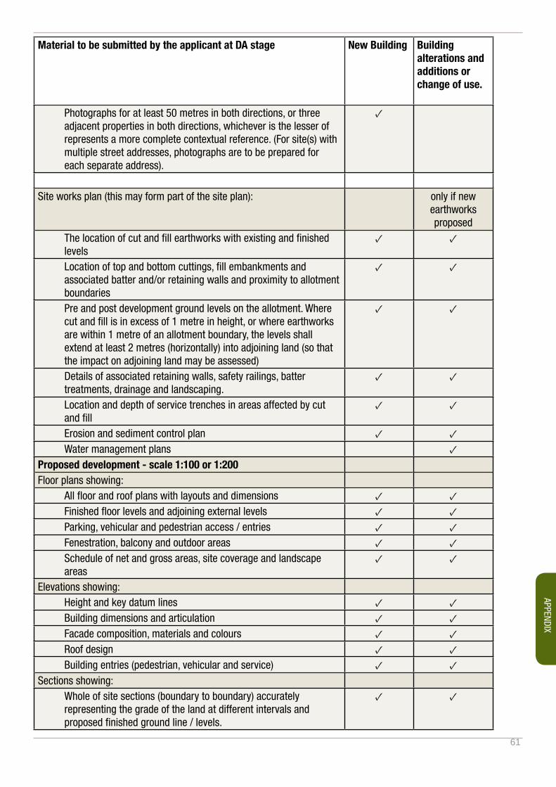
61
Material to be submitted by the applicant at DA stage New Building Building alterations and additions or change of use.
Photographs for at least 50 metres in both directions, or three adjacent properties in both directions, whichever is the lesser of represents a more complete contextual reference. (For site(s) with multiple street addresses, photographs are to be prepared for each separate address).
✓
Site works plan (this may form part of the site plan): only if new earthworks proposed
The location of cut and fill earthworks with existing and finished levels
✓ ✓
Location of top and bottom cuttings, fill embankments and associated batter and/or retaining walls and proximity to allotment boundaries
✓ ✓
Pre and post development ground levels on the allotment. Where cut and fill is in excess of 1 metre in height, or where earthworks are within 1 metre of an allotment boundary, the levels shall extend at least 2 metres (horizontally) into adjoining land (so that the impact on adjoining land may be assessed)
✓ ✓
Details of associated retaining walls, safety railings, batter treatments, drainage and landscaping.
✓ ✓
Location and depth of service trenches in areas affected by cut and fill
✓ ✓
Erosion and sediment control plan ✓ ✓Water management plans ✓
Proposed development - scale 1:100 or 1:200Floor plans showing:
All floor and roof plans with layouts and dimensions ✓ ✓Finished floor levels and adjoining external levels ✓ ✓Parking, vehicular and pedestrian access / entries ✓ ✓Fenestration, balcony and outdoor areas ✓ ✓Schedule of net and gross areas, site coverage and landscape areas
✓ ✓
Elevations showing:Height and key datum lines ✓ ✓Building dimensions and articulation ✓ ✓Facade composition, materials and colours ✓ ✓Roof design ✓ ✓Building entries (pedestrian, vehicular and service) ✓ ✓
Sections showing:Whole of site sections (boundary to boundary) accurately representing the grade of the land at different intervals and proposed finished ground line / levels.
✓ ✓
APPENDIX
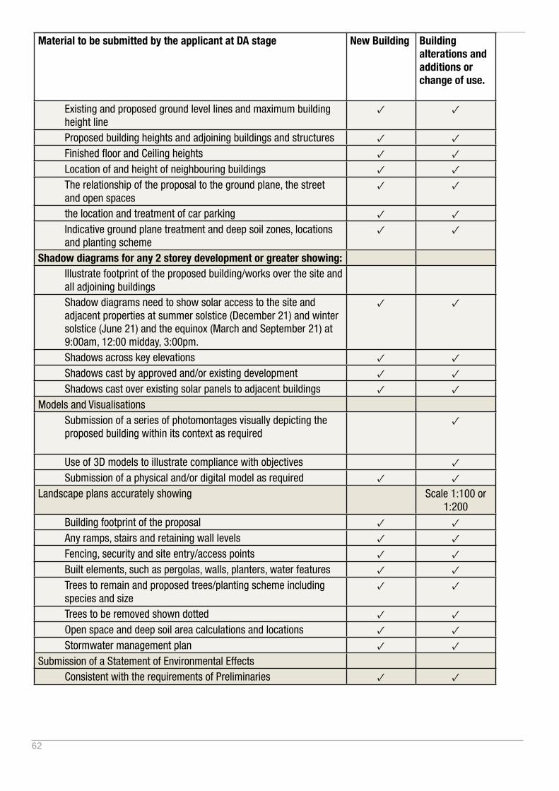
62
Material to be submitted by the applicant at DA stage New Building Building alterations and additions or change of use.
Existing and proposed ground level lines and maximum building height line
✓ ✓
Proposed building heights and adjoining buildings and structures ✓ ✓Finished floor and Ceiling heights ✓ ✓Location of and height of neighbouring buildings ✓ ✓The relationship of the proposal to the ground plane, the street and open spaces
✓ ✓
the location and treatment of car parking ✓ ✓Indicative ground plane treatment and deep soil zones, locations and planting scheme
✓ ✓
Shadow diagrams for any 2 storey development or greater showing:Illustrate footprint of the proposed building/works over the site and all adjoining buildingsShadow diagrams need to show solar access to the site and adjacent properties at summer solstice (December 21) and winter solstice (June 21) and the equinox (March and September 21) at 9:00am, 12:00 midday, 3:00pm.
✓ ✓
Shadows across key elevations ✓ ✓Shadows cast by approved and/or existing development ✓ ✓Shadows cast over existing solar panels to adjacent buildings ✓ ✓
Models and VisualisationsSubmission of a series of photomontages visually depicting the proposed building within its context as required
✓
Use of 3D models to illustrate compliance with objectives ✓Submission of a physical and/or digital model as required ✓ ✓
Landscape plans accurately showing Scale 1:100 or 1:200
Building footprint of the proposal ✓ ✓Any ramps, stairs and retaining wall levels ✓ ✓Fencing, security and site entry/access points ✓ ✓Built elements, such as pergolas, walls, planters, water features ✓ ✓Trees to remain and proposed trees/planting scheme including species and size
✓ ✓
Trees to be removed shown dotted ✓ ✓Open space and deep soil area calculations and locations ✓ ✓Stormwater management plan ✓ ✓
Submission of a Statement of Environmental EffectsConsistent with the requirements of Preliminaries ✓ ✓

63
Note: Where a term is not defined, the DCP relies on the definitions within the Tweed LEP.
9.2. Dictionary applying to this section
Access handle: a strip of land forming part of a site whether in fee-simple or right of way, which has the principle function of providing a property access.
Amenity: the livability or quality of a place which makes it pleasant and agreeable to be in for individuals and the community. Amenity is gained from elements such as sunlight, views, privacy, ambiance and the like.
ANEF contour: Has the same meaning as it has within the State Environmental Planning Policy (Exempt and Complying Development Codes) 2008. Reference is also made to Australian Standard AS2021 Acoustics - Aircraft noise intrusion – Building siting and design.
Articulation Zone: Has the same meaning as it has within the State Environmental Planning Policy (Exempt and Complying Development Codes) 2008.
Balcony: an outdoor, open or partially enclosed area that is either partially integrated into or protrudes entirely from the outer enclosing walls of a building as a means of providing private open space.
BASIX: introduced as part of the NSW planning system, BASIX (the Building Sustainability Index), is a web-based planning tool that measures the potential performance of new buildings against sustainability indices.
Business Park: as the same meaning as prescribed by the Standard Instrument (Local Environment Plans) Order 2006.
Building envelope: a three dimensional zone determined by height, width, depth and setbacks that defines the buildable area on a site.
Building elevation: the external wall of a building.
Building footprint: is area of the building to the extent of the edge of the roof line.
Circulation core: common areas within a development that provide pedestrian movement within the building.
Climate: in the context of this Plan refers to the climatic zones attributed to the Tweed Shire LGA by the Bureau of Meteorology, comprising subtropical (warm humid) and temperate zones.
Communal open space: a designated shared open space area available to the occupants of more than one residential / tourist dwelling and which is under the control of a body corporate or equivalent.
DCP: refers to a Development Control Plan prepared in accordance with the Environmental Planning and Assessment Act 1979.
Deck: refers to an external platform, usually elevated, located alongside and accessible from an interior space.
Deep Soil Zone: means that area of a site with no above ground level or subterranean development, including driveways, paved surfaces, pathways, or like surface, that serves principally for larger tree and landscape plantings.
Demolition: refers to the damaging, defacing destruction, deconstruction, pulling-down, removal or the like of a building in whole or in part.
APPENDIX
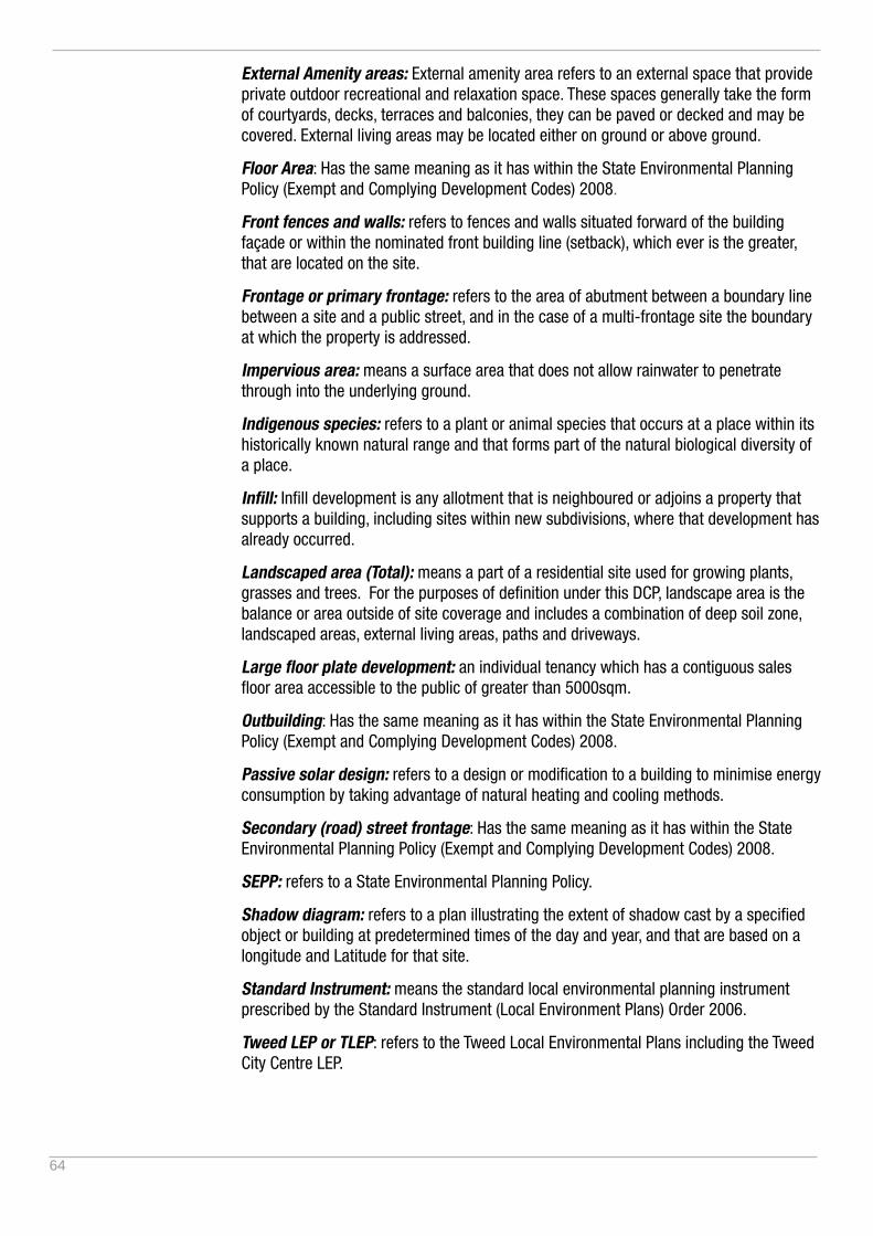
64
External Amenity areas: External amenity area refers to an external space that provide private outdoor recreational and relaxation space. These spaces generally take the form of courtyards, decks, terraces and balconies, they can be paved or decked and may be covered. External living areas may be located either on ground or above ground.
Floor Area: Has the same meaning as it has within the State Environmental Planning Policy (Exempt and Complying Development Codes) 2008.
Front fences and walls: refers to fences and walls situated forward of the building façade or within the nominated front building line (setback), which ever is the greater, that are located on the site.
Frontage or primary frontage: refers to the area of abutment between a boundary line between a site and a public street, and in the case of a multi-frontage site the boundary at which the property is addressed.
Impervious area: means a surface area that does not allow rainwater to penetrate through into the underlying ground.
Indigenous species: refers to a plant or animal species that occurs at a place within its historically known natural range and that forms part of the natural biological diversity of a place.
Infill: Infill development is any allotment that is neighboured or adjoins a property that supports a building, including sites within new subdivisions, where that development has already occurred.
Landscaped area (Total): means a part of a residential site used for growing plants, grasses and trees. For the purposes of definition under this DCP, landscape area is the balance or area outside of site coverage and includes a combination of deep soil zone, landscaped areas, external living areas, paths and driveways.
Large floor plate development: an individual tenancy which has a contiguous sales floor area accessible to the public of greater than 5000sqm.
Outbuilding: Has the same meaning as it has within the State Environmental Planning Policy (Exempt and Complying Development Codes) 2008.
Passive solar design: refers to a design or modification to a building to minimise energy consumption by taking advantage of natural heating and cooling methods.
Secondary (road) street frontage: Has the same meaning as it has within the State Environmental Planning Policy (Exempt and Complying Development Codes) 2008.
SEPP: refers to a State Environmental Planning Policy.
Shadow diagram: refers to a plan illustrating the extent of shadow cast by a specified object or building at predetermined times of the day and year, and that are based on a longitude and Latitude for that site.
Standard Instrument: means the standard local environmental planning instrument prescribed by the Standard Instrument (Local Environment Plans) Order 2006.
Tweed LEP or TLEP: refers to the Tweed Local Environmental Plans including the Tweed City Centre LEP.
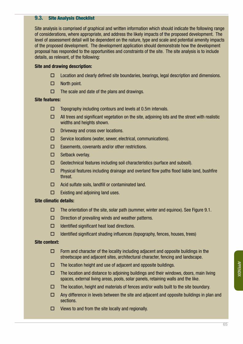
65
9.3. Site Analysis Checklist
Site analysis is comprised of graphical and written information which should indicate the following range of considerations, where appropriate, and address the likely impacts of the proposed development. The level of assessment detail will be dependent on the nature, type and scale and potential amenity impacts of the proposed development. The development application should demonstrate how the development proposal has responded to the opportunities and constraints of the site. The site analysis is to include details, as relevant, of the following:
Site and drawing description:
� Location and clearly defined site boundaries, bearings, legal description and dimensions.
� North point.
� The scale and date of the plans and drawings.
Site features:
� Topography including contours and levels at 0.5m intervals.
� All trees and significant vegetation on the site, adjoining lots and the street with realistic widths and heights shown.
� Driveway and cross over locations.
� Service locations (water, sewer, electrical, communications).
� Easements, covenants and/or other restrictions.
� Setback overlay.
� Geotechnical features including soil characteristics (surface and subsoil).
� Physical features including drainage and overland flow paths flood liable land, bushfire threat.
� Acid sulfate soils, landfill or contaminated land.
� Existing and adjoining land uses.
Site climatic details:
� The orientation of the site, solar path (summer, winter and equinox). See Figure 9.1.
� Direction of prevailing winds and weather patterns.
� Identified significant heat load directions.
� Identified significant shading influences (topography, fences, houses, trees)
Site context:
� Form and character of the locality including adjacent and opposite buildings in the streetscape and adjacent sites, architectural character, fencing and landscape.
� The location height and use of adjacent and opposite buildings.
� The location and distance to adjoining buildings and their windows, doors, main living spaces, external living areas, pools, solar panels, retaining walls and the like.
� The location, height and materials of fences and/or walls built to the site boundary.
� Any difference in levels between the site and adjacent and opposite buildings in plan and sections.
� Views to and from the site locally and regionally.
APPENDIX
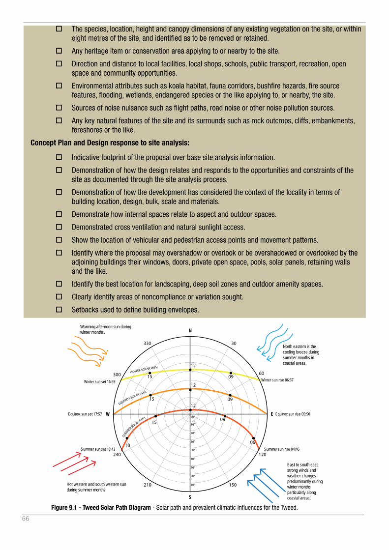
66
� The species, location, height and canopy dimensions of any existing vegetation on the site, or within eight metres of the site, and identified as to be removed or retained.
� Any heritage item or conservation area applying to or nearby to the site.
� Direction and distance to local facilities, local shops, schools, public transport, recreation, open space and community opportunities.
� Environmental attributes such as koala habitat, fauna corridors, bushfire hazards, fire source features, flooding, wetlands, endangered species or the like applying to, or nearby, the site.
� Sources of noise nuisance such as flight paths, road noise or other noise pollution sources.
� Any key natural features of the site and its surrounds such as rock outcrops, cliffs, embankments, foreshores or the like.
Concept Plan and Design response to site analysis:
� Indicative footprint of the proposal over base site analysis information.
� Demonstration of how the design relates and responds to the opportunities and constraints of the site as documented through the site analysis process.
� Demonstration of how the development has considered the context of the locality in terms of building location, design, bulk, scale and materials.
� Demonstrate how internal spaces relate to aspect and outdoor spaces.
� Demonstrated cross ventilation and natural sunlight access.
� Show the location of vehicular and pedestrian access points and movement patterns.
� Identify where the proposal may overshadow or overlook or be overshadowed or overlooked by the adjoining buildings their windows, doors, private open space, pools, solar panels, retaining walls and the like.
� Identify the best location for landscaping, deep soil zones and outdoor amenity spaces.
� Clearly identify areas of noncompliance or variation sought.
� Setbacks used to define building envelopes.
N
S
30
300
330
240
210 150
0618
15
15
15
09
09
09
12
12
12
10°
20°
30°
40°
50°
60°
70°
80°
90°
120
60
W E
SUM
MER SOLAR PATH
Summer sun rise 04:46Summer sun set 18:42
Equinox sun rise 05:50
Winter sun rise 06:37
Equinox sun set 17:57
Winter sun set 16:59
EQUINOX SOLAR PATH
WINTER SOLAR PATH
North eastern is the cooling breeze during summer months in coastal areas.
East to south east strong winds and weather changes predominantly during winter months particularly along coastal areas.
Warming afternoon sun during winter months.
Hot western and south western sun during summer months.
Figure 9.1 - Tweed Solar Path Diagram - Solar path and prevalent climatic influences for the Tweed.
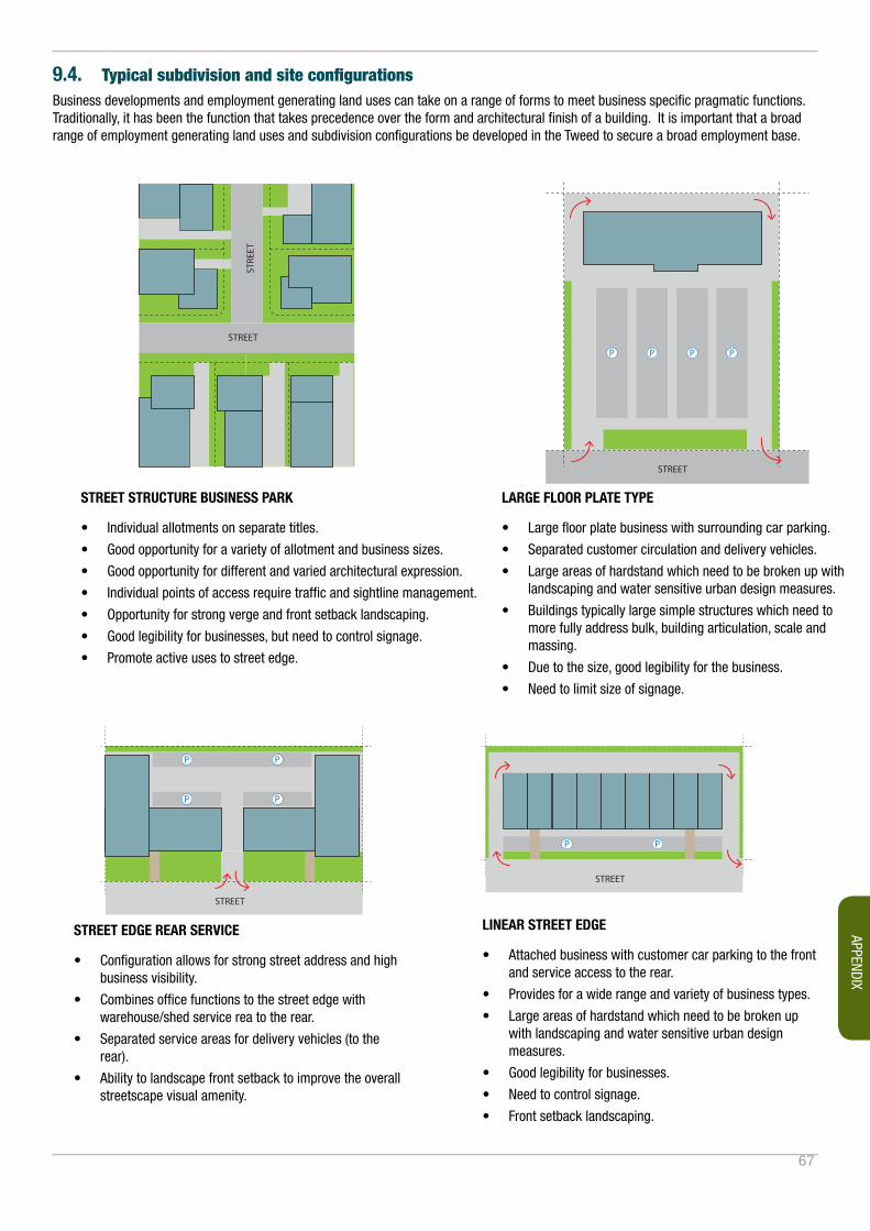
67
P
P P
P
P
P
P
P
P
P
P
PP
PP
STREET
STREET
PP
STREET
STREET
STREET
STREET
STREET
STRE
ET
P P P P
P
P P
P
P
P
P
P
P
P
P
PP
PP
STREET
STREET
PP
STREET
STREET
STREET
STREET
STREET
STRE
ET
P P P P
STREET STRUCTURE BUSINESS PARK
• Individual allotments on separate titles.
• Good opportunity for a variety of allotment and business sizes.
• Good opportunity for different and varied architectural expression.
• Individual points of access require traffic and sightline management.
• Opportunity for strong verge and front setback landscaping.
• Good legibility for businesses, but need to control signage.
• Promote active uses to street edge.
LARGE FLOOR PLATE TYPE
• Large floor plate business with surrounding car parking.
• Separated customer circulation and delivery vehicles.
• Large areas of hardstand which need to be broken up with landscaping and water sensitive urban design measures.
• Buildings typically large simple structures which need to more fully address bulk, building articulation, scale and massing.
• Due to the size, good legibility for the business.
• Need to limit size of signage.
P
P P
P
P
P
P
P
P
P
P
PP
PP
STREET
STREET
PP
STREET
STREET
STREET
STREET
STREET
STRE
ET
P P P P
P
P P
P
P
P
P
P
P
P
P
PP
PP
STREET
STREET
PP
STREET
STREET
STREET
STREET
STREET
STRE
ET
P P P P
LINEAR STREET EDGE
• Attached business with customer car parking to the front and service access to the rear.
• Provides for a wide range and variety of business types.
• Large areas of hardstand which need to be broken up with landscaping and water sensitive urban design measures.
• Good legibility for businesses.
• Need to control signage.
• Front setback landscaping.
STREET EDGE REAR SERVICE
• Configuration allows for strong street address and high business visibility.
• Combines office functions to the street edge with warehouse/shed service rea to the rear.
• Separated service areas for delivery vehicles (to the rear).
• Ability to landscape front setback to improve the overall streetscape visual amenity.
9.4. Typical subdivision and site configurationsBusiness developments and employment generating land uses can take on a range of forms to meet business specific pragmatic functions. Traditionally, it has been the function that takes precedence over the form and architectural finish of a building. It is important that a broad range of employment generating land uses and subdivision configurations be developed in the Tweed to secure a broad employment base.
APPENDIX
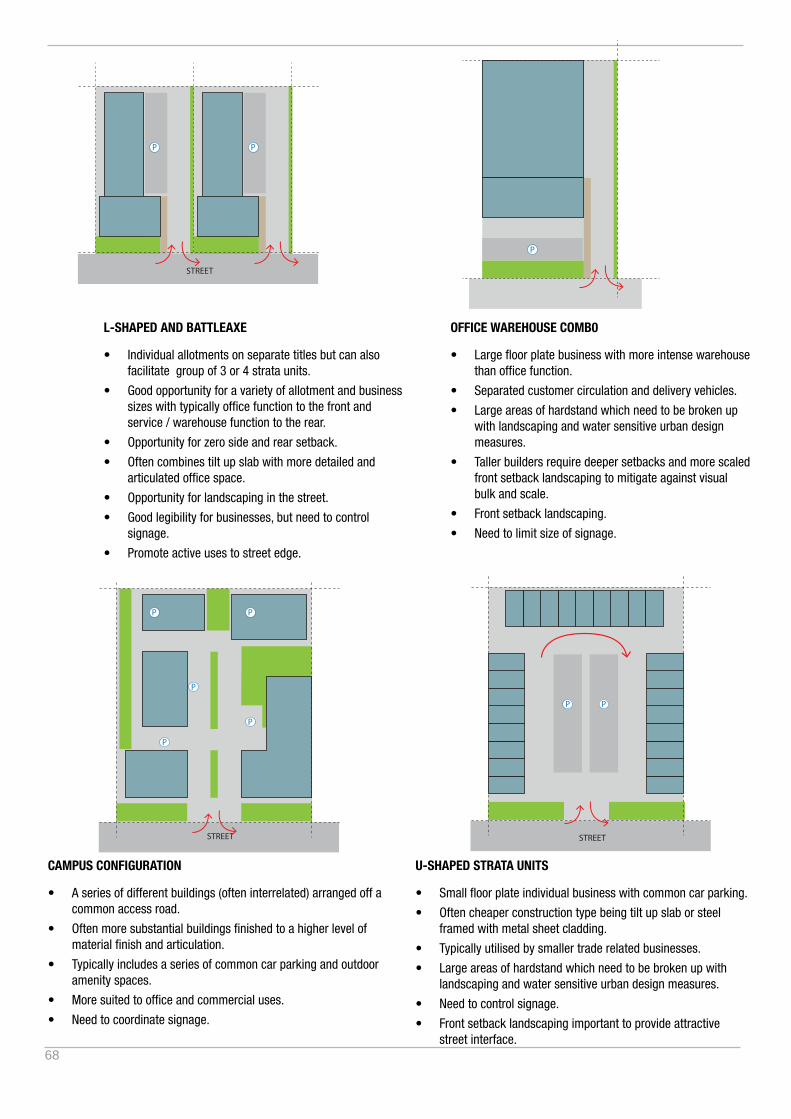
68
P
P P
P
P
P
P
P
P
P
P
PP
PP
STREET
STREET
PP
STREET
STREET
STREET
STREET
STREET
STRE
ET
P P P P
P
P P
P
P
P
P
P
P
P
P
PP
PP
STREET
STREET
PP
STREET
STREET
STREET
STREET
STREET
STRE
ET
P P P P
CAMPUS CONFIGURATION
• A series of different buildings (often interrelated) arranged off a common access road.
• Often more substantial buildings finished to a higher level of material finish and articulation.
• Typically includes a series of common car parking and outdoor amenity spaces.
• More suited to office and commercial uses.
• Need to coordinate signage.
U-SHAPED STRATA UNITS
• Small floor plate individual business with common car parking.
• Often cheaper construction type being tilt up slab or steel framed with metal sheet cladding.
• Typically utilised by smaller trade related businesses.
• Large areas of hardstand which need to be broken up with landscaping and water sensitive urban design measures.
• Need to control signage.
• Front setback landscaping important to provide attractive street interface.
P
P P
P
P
P
P
P
P
P
P
PP
PP
STREET
STREET
PP
STREET
STREET
STREET
STREET
STREET
STRE
ET
P P P P
P
P P
P
P
P
P
P
P
P
P
PP
PP
STREET
STREET
PP
STREET
STREET
STREET
STREET
STREET
STRE
ET
P P P P
L-SHAPED AND BATTLEAXE
• Individual allotments on separate titles but can also facilitate group of 3 or 4 strata units.
• Good opportunity for a variety of allotment and business sizes with typically office function to the front and service / warehouse function to the rear.
• Opportunity for zero side and rear setback.
• Often combines tilt up slab with more detailed and articulated office space.
• Opportunity for landscaping in the street.
• Good legibility for businesses, but need to control signage.
• Promote active uses to street edge.
OFFICE WAREHOUSE COMB0
• Large floor plate business with more intense warehouse than office function.
• Separated customer circulation and delivery vehicles.
• Large areas of hardstand which need to be broken up with landscaping and water sensitive urban design measures.
• Taller builders require deeper setbacks and more scaled front setback landscaping to mitigate against visual bulk and scale.
• Front setback landscaping.
• Need to limit size of signage.

69
APPENDIX