Embed Size (px)
Citation preview

BOC Certification Exam Resource Guide - Section A
1 © 2017 Northwest Energy Efficiency Council
BOCCertificationExamResourceGuide
Section A- Maintain Energy Using Building Systems, Equipment, and Envelope to Minimize Energy Use Citations
INTRODUCTION Section A of the exam covers the critical work functions for Maintaining Energy Using Building Systems, Equipment and Envelope to Minimize Energy Use. The reading list in this resource guide is targeted to the content of the exam questions in this section of the exam. It is organized by topic area as noted in the Table of Contents.
Each section provides the source of the citation, a link to where it can be found online, and a set of study questions about the content in the citation, followed by a paragraph or two of the material specific to the exam question. The study questions serve as guidance for independent study as candidates prepare for the exam. In addition to the study questions, the reading list provides practice questions and answers from the early versions of the certification exam. The study questions and practice questions are also covered in the BOC Exam Prep Webinar Series (http://www.theboc.info/certifications/exam/preparing-for-exam/). Additional resources are provided in the form of PDF documents which provide further discussion and useful illustrations, tables and figures. We recommend exam candidates familiarize themselves with the content and be prepared to answer the questions posed in each section.
Study Questions: These questions provide guidance for independent study of the topics in the Resource Guide. Study questions do not represent actual questions on the certification exam. Study questions appear under each citation in this document.
Practice Questions: These are questions that appeared on earlier versions of the certification exam and which have been retired from circulation. Practice questions are provided on the last page of this document.
Section A - Exam Blueprint Skill Areas and Number of Questions Perform preventive & predictive maintenance (10 questions)
• Conduct equipment checks • Conduct facility maintenance rounds • Coordinate normal facility operations • Maintain the facility and systems • Conduct facility repair activities • Perform regularly scheduled maintenance activities • Manage outside facility contractors/service providers
BOC Certification Exam Resource Guide - Section A
2 © 2017 Northwest Energy Efficiency Council
• Conduct a building walk-through inspection • Respond to building emergencies
Troubleshoot system, equipment problems & perform diagnostics (9 questions)
• Perform workplace hazard assessments • Participate in emergency drills • Coordinate facility operations (other than normal) • Use diagnostic tools to detect equipment degradation. • Troubleshoot HVAC, electrical and building automation systems. • Respond to tenant requests/issues • Document diagnostic test results
Document equipment maintenance (12 questions)
• Deal with the personal protection equipment program • Manage third party inspections • Conduct risk management activities • Read circuit diagrams to identify power sources, controls, paths, and calculate loads • Read manufacturer specifications and as-built building system drawings to recommend
preventive maintenance requirements • Maintain equipment logs and parts inventories in a maintenance management system • Update operations and maintenance manuals for building systems
Table of Contents 1. Perform Predictive & Preventive Maintenance
• Predictive Maintenance Technologies • HVAC Systems and Equipment
o Oil Burner Maintenance o Pump System Maintenance o Chiller and Cooling Tower Maintenance o Air Handling Systems o Damper Maintenance o Air Filter Maintenance
• Refrigeration Cycle and Systems o Refrigeration Compressors & Evaporators o HVAC Refrigerants o Suction Line Accumulator o Liquid Receiver
• Electrical Systems o Wiring a 2-way Switch o Wiring Color Codes o Electrical Insulation
BOC Certification Exam Resource Guide - Section A
3 © 2017 Northwest Energy Efficiency Council
o Capacitors
2. Troubleshoot system & equipment problems & perform diagnostic testing
• Compressed Air Systems - Find & Fix Compressed Air Leaks • Water Systems - Water Leaks – Leaky Faucets • HVAC Systems
o Sling psychrometer o Economizer and Mixed Air o Air Conditioner Fin Repair Tool
• Building Envelope o Reducing Air Leaks - Infiltration & Exfiltration o Fire Smoke System Damper and Actuator Maintenance o Maintenance of Cool Roofs
• Electrical Systems o Detecting Failing Electrical Connections o Testing and maintaining Exit & Emergency lighting systems: o OSHA Code of Federal Regulations o NFPA 70 - National Electric Code o Starting & Warm Up, Metal-Halide Lamp o VFD Operation & Maintenance
• Building Control System Maintenance o Pneumatic Controls, Controls & Features o Building Automation Systems (BAS) o Air-Side Economizer Operation & Verification o Air Flow Measurements
3. Document equipment maintenance
• Preventive Maintenance Practices o Computerized maintenance management system (CMMS) o CMMS Equipment o CMMS Reports
• Electrical Systems o Ohm's Law o Energy Code Requirements for Occupancy Sensors o Light colors for interior finishes o How to read a motor nameplate
• HVAC Systems o HVAC PM log o Refrigerant Recycling Rule o Refrigerant charging records o Major Recordkeeping Requirements for Stationary Refrigeration o General Maintenance Checklist for HVAC Contractors o Retro-Commissioning

BOC Certification Exam Resource Guide - Section A
4 © 2017 Northwest Energy Efficiency Council
4. Practice Questions & Answers
Reading List
Area 1 - Perform Predictive & Preventive Maintenance
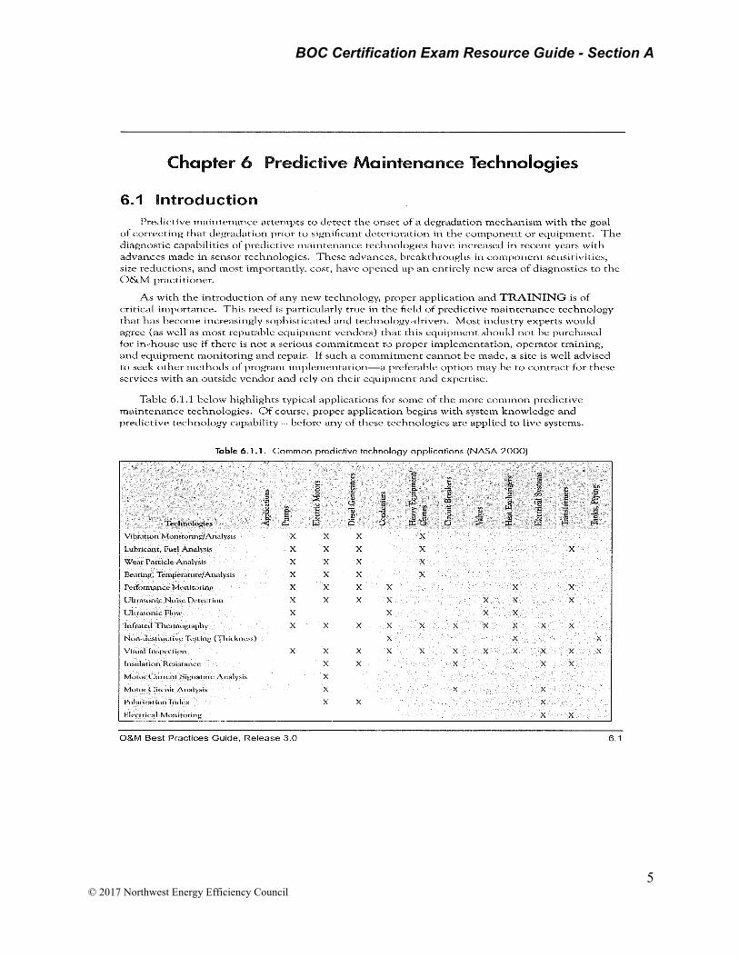
Chapter 6 Predictive Maintenance Technologies, O&M Best Practices Guide, Release 3.0 http://www1.eere.energy.gov/femp/pdfs/OM_6.pdf
STUDY QUESTIONS: Ultrasonic flow detection is a technology that could be applied to what systems to predict maintenance needs?
______________________________________________________________________
Vibration monitoring analysis is appropriate for what systems and equipment?
______________________________________________________________________
What type of radiation energy does Thermographic equipment detect to assess equipment condition?
______________________________________________________________________
BOC Certification Exam Resource Guide - Section A
5 © 2017 Northwest Energy Efficiency Council
BOC Certification Exam Resource Guide - Section A
6 © 2017 Northwest Energy Efficiency Council
HVAC Systems and Equipment
Oil Burner Maintenance Landa Technical College – Power Point Cost Saving Burner Efficiency Maintenance http://www.ikeca.org/sites/default/files/Workshop_201+102_Pressure_Washer_Maintenance-Randy_Rauth_1.pdf
Alternate resource - http://www.oemboilerparts.com/phone/manuals/KR-manual.pdf
STUDY QUESTIONS: What items should be checked in porcelain insulators and electrode tips when inspecting burner nozzles and electrode maintenance? Answer: Check for cracks in porcelain insulators and make sure electrodes have well defined tips.
____________________________________________________________________
What are the maintenance steps for oil burner electrodes and the nozzle assembly?
______________________________________________________________________
What is the recommended frequency of maintenance?
______________________________________________________________________
Electrode and Burner Nozzle Assembly Maintenance
• Oil burner electrodes – This is very important for reliable ignition of the fuel oil; check once a year.
• Oil burner nozzle and assembly – The nozzle should be changed at least once a year. Replace with proper nozzle. Handle nozzles by hex only. Oil and contaminants from the fingers on the face or filter of nozzle may adversely affect spray characteristics.
Fuel Filter and Tank Maintenance
• Filter – The oil filter cartridge should be replaced once a year so the fuel oil will not become contaminated and plug up fuel pump and nozzle of the oil burner.
• Fuel tank – The fuel tank should be cleaned once each year to prevent contaminants from blocking fuel lines affecting combustion.
Pump System Maintenance http://www.metropumps.com/Metro%20PM%20program%20linecard%2011-6-08%20Rev%2011-20.pdf Review the Pump Maintenance Checklist. See PDF in Appendix.
BOC Certification Exam Resource Guide - Section A
7 © 2017 Northwest Energy Efficiency Council
Most pump maintenance activities center on checking packing and mechanical seals for leakage, performing maintenance activities on bearings, assuring proper alignment, and validating proper motor condition and function without consideration for pump efficiency. Improving efficiency will decrease both maintenance and operating costs.
STUDY QUESTIONS:
What are examples of basic measures to improve pump efficiency?
______________________________________________________________________
What are the most likely candidates for pump efficiency measures?
______________________________________________________________________
Chiller Maintenance for energy efficiency
O&M Best Practices Guide, Release 3.0 https://energy.gov/sites/prod/files/2013/10/f3/omguide_complete.pdf
STUDY QUESTIONS: Name two safety precautions for refrigerants used in large chillers.
______________________________________________________________________
What maintenance steps can be taken to improve chiller performance and energy efficiency?
______________________________________________________________________
On a centrifugal chiller, if the condenser water temperature is decreased by 2˚F to 3˚F, the system efficiency can increase by as much as ________________?
On a centrifugal chiller, if the chilled water temperature is raised by 2˚F to 3˚F, the system efficiency can increase by as much as ________________?
How does retrofitting a cooling tower with ozonation or ionization water treatment reduce the maintenance requirements?
______________________________________________________________________
9.4.4 Safety Issues (TARAP 2001) Large chillers are most commonly located in mechanical equipment rooms within the building they are air conditioning. If a hazardous refrigerant is used (e.g., ammonia), the equipment room must meet additional requirements typically including minimum ventilation airflows and vapor concentration monitoring. In many urban code jurisdictions, the use of ammonia as a refrigerant is prohibited outright. For large chillers, the refrigerant charge is too large to allow hydrocarbon refrigerants in chillers located in a mechanical equipment room.

BOC Certification Exam Resource Guide - Section A
8 © 2017 Northwest Energy Efficiency Council
9.4.5 Cost and Energy Efficiency (Dyer and Maples 1995) The following steps describe ways to improve chiller performance, therefore, reducing its operating costs:
• Raise chilled water temperature – The energy input required for any liquid chiller (mechanical compression or absorption) increases as the temperature lift between the evaporator and the condenser increases. Raising the chilled water temperature will cause a corresponding increase in the evaporator temperature and thus, decrease the required temperature lift.
• Reduce condenser water temperature – The effect of reducing condenser water temperature is very similar to that of raising the chilled water temperature, namely reducing the temperature lift that must be supplied by the chiller.
• Reducing scale or fouling – The heat transfer surfaces in chillers tends to collect various mineral and sludge deposits from the water that is circulated through them. Any buildup insulates the tubes in the heat exchanger causing a decrease in heat exchanger efficiency and thus, requiring a large temperature difference between the water and the refrigerant.
• Purge air from condenser – Air trapped in the condenser causes an increased pressure at the compressor discharge. This results in increased compressor horsepower. The result has the same effect as scale buildup in the condenser.
• Maintain adequate condenser water flow – Most chillers include a filter in the condenser water line to remove material picked up in the cooling tower. Blockage in this filter at higher loads will cause an increase in condenser refrigerant temperature due to poor heat transfer.
• Reducing auxiliary power requirements – The total energy cost of producing chilled water is not limited to the cost of operating the chiller itself. Cooling tower fans, condenser water circulating pumps, and chilled water circulating pumps must also be included. Reduce these requirements as much as possible.
On a centrifugal chiller, if the condenser water temperature is decreased by 2˚F to 3˚F, the system efficiency can increase by as much as 2% to 3%.
On a centrifugal chiller, if the chilled water temperature is raised by 2˚F to 3˚F, the system efficiency can increase by as much as 3% to 5%.
9.67 – Cooling Tower Retrofit Opportunities to manage maintenance
• Install a sidestream filtration system that is composed of a rapid sand filter or high-efficiency cartridge filter to cleanse the water. These systems draw water from the sump, filter out sediments and return the filtered water to the tower, enabling the system to operate more efficiently with less water and chemicals. Sidestream filtration is particularly helpful if your system is subject to dusty atmospheric conditions. Sidestream filtration can turn a troublesome system into a more trouble-free system.
• Install a make-up water softening system when hardness (calcium and magnesium) is the limiting factor on your cycles of concentration. Water softening removes hardness using an ion exchange resin, and can allow you to operate at higher cycles of concentration.
• Install covers to block sunlight penetration. Reducing the amount of sunlight on tower surfaces can significantly reduce biological growth such as algae.
BOC Certification Exam Resource Guide - Section A
9 © 2017 Northwest Energy Efficiency Council
• Consider alternative water treatment options such as ozonation or ionization, to reduce water and chemical usage. Be careful to consider the life-cycle cost impact of such systems such as increased maintenance cost of such systems and increase electrical consumption and cost. NOTE: Ionization may reduce maintenance cost due to water and chemical savings but may also increase energy and maintenance costs due to O&M requirements of the ionization system. Full life cycle cost and benefit analysis must be conducted to compare both programs.
• Install automated chemical feed systems on large cooling tower systems (over 100 ton). The automated feed system should control blowdown/bleed-off by conductivity and then add chemicals based on make-up water flow. These systems minimize water and chemical use while optimizing control against scale, corrosion, and biological growth.
Air Handling Systems O&M Best Practices Guide, Release 3.0 https://energy.gov/sites/prod/files/2013/10/f3/omguide_complete.pdf
STUDY QUESTIONS: What is the difference between a constant volume (CV) and variable-air volume (VAV) air handling system?
______________________________________________________________________
Airflow through a filter bank should be as uniform across the entire filter surface area. What is the recommended flow rate in feet per minute (fpm)?
______________________________________________________________________
What is the most reliable way to assess filter condition to determine the need for replacement?
______________________________________________________________________
BOC Certification Exam Resource Guide - Section A
10 © 2017 Northwest Energy Efficiency Council
9.7.1 Introduction
The components of most air handling systems include fans, ductwork, damper assemblies, heating and cooling coils (or elements), and associated sensors.
9.7.2 Types of Air Handling Systems
Most air handling systems fall into two broad categories, constant-volume (CV) and variable-air volume (VAV). The following descriptions provide an overview of generic system types commonly found in larger commercial and institutional buildings (Better Bricks 2008).
Constant Air Volume. Constant air volume systems provide a constant airflow rate to the zone. The control variable is the temperature of the air supplied to the zone. These systems can be configured for single-zone or multi-zone systems and may be configured as a single duct or two duct (dual duct) system.
Variable Air Volume. VAV systems provide comfort by changing the volume of air delivered to a zone based on temperature needs and controlled by static pressure measured in the duct system. Most VAV systems are single duct systems and provide cooling and ventilation – when necessary, air is heated often at the terminal unit.
9.7.3 Key Components
• Fans – This topic will be addressed in Section 9.8 • Coils – Coils provide the mechanism for heat transfer between the air stream and the
heat-exchange fluid (usually water, steam or refrigerant). These coils are made of tubes that carry the fluid and are surrounded by rows of thin fins designed to increase the heat-transfer surface area. For maximum heat transfer, it is imperative to keep these coils clean and free of obstructions.
• Filters – With the goal of efficient heat transfer and good air quality, filters are used to prevent particulate matter or other contaminants from entering (or re-circulating) though an air handling system. Filters are classified by ASHRAE Standard 52.2 and rated by their Minimum Efficiency Reporting Value (MERV). By design, the airflow through a filter bank should be as uniform across the entire filter surface area and, depending on the filter type and design, in the range of 400 to 600 feet per minute (fpm). Filters are a required maintenance item and should be changed based on system use and contaminant loading.
• Dampers – To control and direct the flow of air through the system, dampers are installed at the inlet, the outlet, or internal to the air handling system. There are a variety of damper types and configurations. Dampers are a notorious source of energy waste via leakage, malfunction, or being disabled. Due to their typical location and challenges associated with proper assessment, damper assemblies are often not addressed in standard maintenance practices.
• Ducts – The ducts found in most commercial facilities are usually made of galvanized steel and are insulated to reduce heat transfer and prevent condensation. Duct connections from section to section, or at the terminal apparatus, need to be done according local code requirements and should be checked annually for integrity.

BOC Certification Exam Resource Guide - Section A
11 © 2017 Northwest Energy Efficiency Council
9.7.4 Cost and Energy Efficiency
Many air handling system efficiency measures relate to how the system is controlled and are covered in Section 9.6 Energy Management and Building Automation Systems. Additional measures for consideration are presented below.
Filters – Air filters play a critical role in maintaining indoor air quality and protecting the downstream components of the system from dirt that reduces equipment efficiency. In the worst case, dirty filters can result in supply air bypassing the filter and depositing dirt on the heating/ cooling coils rather than on the filter. This results in dirty coils, poor heat transfer, and general inefficiency. In addition to the efficiency penalty, cleaning a dirty coil is far more difficult and labor intensive than replacing filters (DOE 2005). As a rule, sites should routinely change filters based on either the pressure drop across the filter, calendar scheduling, or visual inspection. Scheduled intervals should be between 1 and 6 months, depending on the dirt loading from indoor and outdoor air. Measuring the pressure drop across the filter is the most reliable way to assess filter condition. In facilities with regular and predictable dirt loading, measuring the pressure drop across the filter can be used to establish the proper filter-changing interval; thereafter, filter changes can be routinely scheduled. Refer to manufacturer’s data for the recommendations of pressure drop across specific filters.
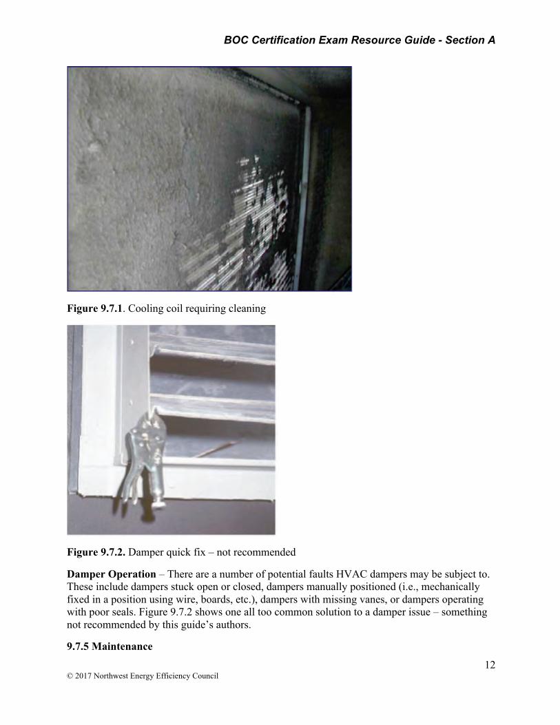
Coil Cleaning – Hot water and chilled water coils in HVAC systems tend to accumulate dirt and debris, similarly to HVAC filters. As dirt and debris accumulates, it inhibits the heat transferred from the working fluid to the air stream, thus reducing the efficiency of the HVAC system. Much like HVAC filters, the scheduled intervals between cleanings is a function of the dirt loading across the coil and is primarily a function of how much dirt is in the ambient air and what has bypassed the filter. Based on the site’s periodic inspections, the given facility should develop appropriate cleaning schedules for all of the hot water and chilled water coils. Figure 9.7.1 presents a cooling coil in great need of maintenance.
BOC Certification Exam Resource Guide - Section A
12 © 2017 Northwest Energy Efficiency Council
Figure 9.7.1. Cooling coil requiring cleaning
Figure 9.7.2. Damper quick fix – not recommended
Damper Operation – There are a number of potential faults HVAC dampers may be subject to. These include dampers stuck open or closed, dampers manually positioned (i.e., mechanically fixed in a position using wire, boards, etc.), dampers with missing vanes, or dampers operating with poor seals. Figure 9.7.2 shows one all too common solution to a damper issue – something not recommended by this guide’s authors.
9.7.5 Maintenance
BOC Certification Exam Resource Guide - Section A
13 © 2017 Northwest Energy Efficiency Council
Proper maintenance for air handling systems includes scheduled filter replacement, coil cleaning, duct integrity evaluation, damper cleanliness and function.
9.7.5.1 Diagnostic Tools
The combination of a facility’s building automation system and occupant interaction can be very diagnostic of an air handling systems function. Repeated cold/warm complaint calls, validated through the BAS sensor readings, can be indicative of a poorly performing system in need of maintenance.
Damper Maintenance - General http://www.safeair-dowco.com/product/Operation%20and%20Maintenance.pdf
STUDY QUESTIONS: What are standard maintenance steps for dampers?
______________________________________________________________________
What is the recommended inspection and service interval for all automatic dampers?
______________________________________________________________________
What are precautions to take when lubricating movable dampers parts?
______________________________________________________________________
What features of newer dampers can be incorporated into existing damper installations to improve performance?
______________________________________________________________________
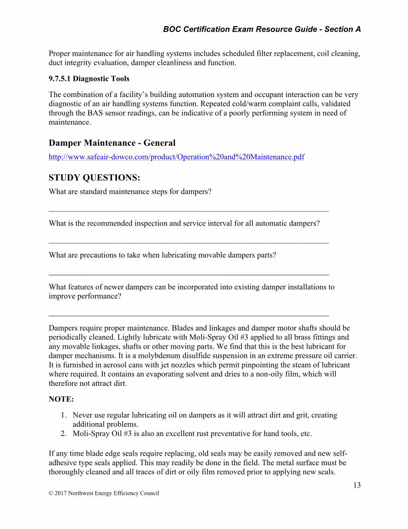
Dampers require proper maintenance. Blades and linkages and damper motor shafts should be periodically cleaned. Lightly lubricate with Moli-Spray Oil #3 applied to all brass fittings and any movable linkages, shafts or other moving parts. We find that this is the best lubricant for damper mechanisms. It is a molybdenum disulfide suspension in an extreme pressure oil carrier. It is furnished in aerosol cans with jet nozzles which permit pinpointing the steam of lubricant where required. It contains an evaporating solvent and dries to a non-oily film, which will therefore not attract dirt.
NOTE:
1. Never use regular lubricating oil on dampers as it will attract dirt and grit, creating additional problems.
2. Moli-Spray Oil #3 is also an excellent rust preventative for hand tools, etc.
If any time blade edge seals require replacing, old seals may be easily removed and new self-adhesive type seals applied. This may readily be done in the field. The metal surface must be thoroughly cleaned and all traces of dirt or oily film removed prior to applying new seals.
BOC Certification Exam Resource Guide - Section A
14 © 2017 Northwest Energy Efficiency Council
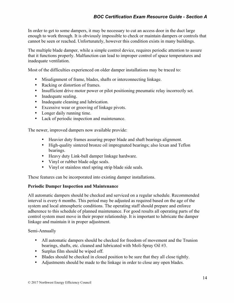
In order to get to some dampers, it may be necessary to cut an access door in the duct large enough to work through. It is obviously impossible to check or maintain dampers or controls that cannot be seen or reached. Unfortunately, however this condition exists in many buildings.
The multiple blade damper, while a simple control device, requires periodic attention to assure that it functions properly. Malfunction can lead to improper control of space temperatures and inadequate ventilation.
Most of the difficulties experienced on older damper installations may be traced to:
• Misalignment of frame, blades, shafts or interconnecting linkage. • Racking or distortion of frames. • Insufficient drive motor power or pilot positioning pneumatic relay incorrectly set. • Inadequate sealing. • Inadequate cleaning and lubrication. • Excessive wear or grooving of linkage pivots. • Longer daily running time. • Lack of periodic inspection and maintenance.
The newer, improved dampers now available provide:
• Heavier duty frames assuring proper blade and shaft bearings alignment. • High-quality sintered bronze oil impregnated bearings; also lexan and Teflon
bearings. • Heavy duty Link-ball damper linkage hardware. • Vinyl or rubber blade edge seals. • Vinyl or stainless steel spring strip blade side seals.
These features can be incorporated into existing damper installations.
Periodic Damper Inspection and Maintenance
All automatic dampers should be checked and serviced on a regular schedule. Recommended interval is every 6 months. This period may be adjusted as required based on the age of the system and local atmospheric conditions. The operating staff should prepare and enforce adherence to this schedule of planned maintenance. For good results all operating parts of the control system must move in their proper relationship. It is important to lubricate the damper linkage and maintain it in proper adjustment.
Semi-Annually
• All automatic dampers should be checked for freedom of movement and the Trunion bearings, shafts, etc. cleaned and lubricated with Moli-Spray Oil #3.
• Surplus film should be wiped off. • Blades should be checked in closed position to be sure that they all close tightly. • Adjustments should be made to the linkage in order to close any open blades.

BOC Certification Exam Resource Guide - Section A
15 © 2017 Northwest Energy Efficiency Council
• Damper motors should be observed through an operating cycle to check for defects or binding.
• Damper motor anchorage should also be checked. • Damaged blades should be repaired or replaced. Dirt, soot, lint, etc. should not be
permitted to accumulate on blades, as this will increase resistance, weight and present an unsightly
• appearance. • Caulking that was used to make damper frames tight to structure should be checked and • repaired as needed.
Air Filter Replacement http://hpac.com/fastrack/matela-06-08
STUDY QUESTIONS: How are filters classified and rated?
______________________________________________________________________
For general HVAC applications, a MERV of 1 is least efficient, while a MERV of 16 is most efficient. What is the current minimum MERV rating requirement, according to ASHRAE Standard 62.1, Ventilation for Acceptable Indoor Air Quality?
______________________________________________________________________
Once filters are specified and installed, establishing an appropriate filter change-out frequency is crucial. If schedules allow, filter change outs should occur when a facility is unoccupied. Performance values for replacement filters should be reviewed to ensure pressure drop or airflow resistance across a filter will not be too great, especially as the filter loads. Greater resistance reduces airflow to an HVAC unit, negatively impacting heating/cooling and energy efficiency.

BOC Certification Exam Resource Guide - Section A
16 © 2017 Northwest Energy Efficiency Council
ASHRAE Standards The 2007 version of ASHRAE Standard 52.2 quantifies the fractional particle-size efficiency of filters at various particle sizes. A test indicates a filter's ability to remove airborne particles with diameters between 0.3 and 10 microns (Table 1).
TABLE 1. The higher the MERV levels, the greater the ability to remove large quantities of small particles from air.
A MERV is assigned to a filter depending on particle-size efficiency in three particle-size ranges: 0.3 to 1 micron, 1 to 3 microns, and 3 to 10 microns. MERVs range from 1 to 16, but high-efficiency-particulate-air (HEPA) filters, which have MERVs of 17 to 20, are tested with different standards. For general HVAC applications, a MERV of 1 is least efficient, while a MERV of 16 is most efficient. Recent studies suggest that a MERV of 8 is enough to provide good HVAC-system cleanliness and efficient operation, even though the current minimum requirement, according to ASHRAE Standard 62.1, Ventilation for Acceptable Indoor Air Quality, is a MERV of 6.
Air Conditioner Maintenance - Filters http://www.energy.gov/energysaver/articles/maintaining-your-air-conditioner
STUDY QUESTIONS: What is the impact of a dirty air filter on an air conditioner coil?
______________________________________________________________________

BOC Certification Exam Resource Guide - Section A
17 © 2017 Northwest Energy Efficiency Council
What is the impact of dirt on an air conditioner coil?
______________________________________________________________________
How frequently should an evaporator coil be checked for cleaning?
______________________________________________________________________
Air Conditioner Filters
The most important maintenance task that will ensure the efficiency of your air conditioner is to routinely replace or clean its filters. Clogged, dirty filters block normal airflow and reduce a system's efficiency significantly. With normal airflow obstructed, air that bypasses the filter may carry dirt directly into the evaporator coil and impair the coil's heat-absorbing capacity. Replacing a dirty, clogged filter with a clean one can lower your air conditioner's energy consumption by 5% to 15%.
For central air conditioners, filters are generally located somewhere along the return duct's length. Common filter locations are in walls, ceilings, furnaces, or in the air conditioner itself. Room air conditioners have a filter mounted in the grill that faces into the room.
Some types of filters are reusable; others must be replaced. They are available in a variety of types and efficiencies. Clean or replace your air conditioning system's filter or filters every month or two during the cooling season. Filters may need more frequent attention if the air conditioner is in constant use, is subjected to dusty conditions, or you have fur-bearing pets in the house.
Air Conditioner Coils
The air conditioner's evaporator coil and condenser coil collect dirt over their months and years of service. A clean filter prevents the evaporator coil from soiling quickly. In time, however, the evaporator coil will still collect dirt. This dirt reduces airflow and insulates the coil, reducing its ability to absorb heat. To avoid this problem, check your evaporator coil every year and clean it as necessary.
Outdoor condenser coils can also become very dirty if the outdoor environment is dusty or if there is foliage nearby. You can easily see the condenser coil and notice if dirt is collecting on its fins.
You should minimize dirt and debris near the condenser unit. Your dryer vents, falling leaves, and lawn mower are all potential sources of dirt and debris. Cleaning the area around the coil, removing any debris, and trimming foliage back at least 2 feet (0.6 meters) allow for adequate airflow around the condenser.
Coil Fins
The aluminum fins on evaporator and condenser coils are easily bent and can block airflow through the coil. Air conditioning wholesalers sell a tool called a "fin comb" that will comb these fins back into nearly original condition.
BOC Certification Exam Resource Guide - Section A
18 © 2017 Northwest Energy Efficiency Council
Condensate Drains
Occasionally pass a stiff wire through the unit's drain channels. Clogged drain channels prevent a unit from reducing humidity, and the resulting excess moisture may discolor walls or carpet.
Refrigeration Cycle and Systems
STUDY QUESTIONS: The metering device is one of 4 main components in a refrigeration system. It meters the flow of refrigerant into the evaporator. What is its function?
______________________________________________________________________
Describe the roles of the compressor, evaporator, and condenser in the refrigeration cycle.
______________________________________________________________________
A TX Valve is very common type of metering device. How does it work?
______________________________________________________________________
How does it protect against liquid slugging?
______________________________________________________________________
What additional component is necessary in order for the TX Valve to work?
______________________________________________________________________
What does the refrigeration compressor do?
______________________________________________________________________
Refrigeration Basics – Main Components and Metering Device https://www.refrigerationbasics.com/RBIII/rb2.htm
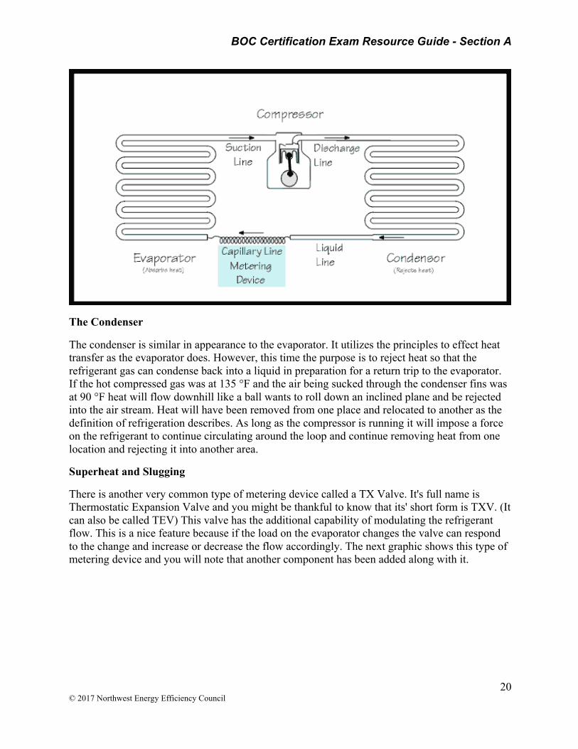
There are 4 main components in a mechanical refrigeration system – the compressor, the evaporator, the metering device and the condenser. Any components beyond these basic 4 are called accessories. The compressor is a vapor compression pump which uses pistons or some other method to compress the refrigerant gas and send it on its way to the condenser. The condenser is a heat exchanger which removes heat from the hot compressed gas and allows it to condense into a liquid. The liquid refrigerant is then routed to the metering device. This device restricts the flow by forcing the refrigerant to go through a small hole which causes a pressure drop. And what did we say happens to a liquid when the pressure drops? If you said it lowers the boiling point and makes it easier to evaporate, then you are correct. And what happens when a liquid evaporates? Didn't we agree that the liquid will absorb heat from the surrounding area? This is indeed the case and you now know how refrigeration works. This component where the evaporation takes place is called the evaporator. The refrigerant is then routed back to the

BOC Certification Exam Resource Guide - Section A
19 © 2017 Northwest Energy Efficiency Council
compressor to complete the cycle. The refrigerant is used over and over again absorbing heat from one area and relocating it to another. Remember the definition of refrigeration? (the removal and relocation of heat)
Heat Transfer Rates
One thing that we would like to optimize in the refrigeration loop is the rate of heat transfer. Materials like copper and aluminum are used because they have very good thermal conductivity. In other words heat can travel through them easily. Increasing surface area is another way to improve heat transfer. Have you noticed that small engines have cooling fins formed into the casting around the piston area? This is an example of increasing the surface area in order to increase the heat transfer rate. The hot engine can more easily reject the unwanted heat through the large surface area of the fins exposed to the passing air. Refrigeration heat transfer devices such as air cooled condensers and evaporators are often made out of copper pipes with aluminum fins and further enhanced with fans to force air through the fins.
Metering Device
We will now take a closer look at the individual components of the system. We will start with the metering device. There are several types but all perform the same general function which is to cause a pressure drop. There should be a full column of high pressure liquid refrigerant (in the liquid line) supplying the inlet of the metering device. When it is forced to go through a small orifice it loses a lot of the pressure it had on the upstream side of the device. The liquid refrigerant is sort of misted into the evaporator. So not only is the pressure reduced, the surface area of the liquid is vastly increased. It is hard to try and light a log with a match but chop the log into toothpick sized slivers and the pile will go up in smoke easily. The surface area of zillions of liquid droplets is much greater than the surface area of the column of liquid in the pipe feeding the metering device. The device has this name because it meters the flow of refrigerant into the evaporator. The next graphic shows a capillary line metering device. This is a long small tube which has an inside diameter much smaller than a pencil lead. You can imagine the large pressure drop when the liquid from a 1/4 or 3/8 in or larger pipe is forced to go through such a small opening. The capillary line has no moving parts and cannot respond to changing conditions like a changing thermal load on the evaporator. Some labels have been added showing the names of some of the pipes.
BOC Certification Exam Resource Guide - Section A
20 © 2017 Northwest Energy Efficiency Council
The Condenser
The condenser is similar in appearance to the evaporator. It utilizes the principles to effect heat transfer as the evaporator does. However, this time the purpose is to reject heat so that the refrigerant gas can condense back into a liquid in preparation for a return trip to the evaporator. If the hot compressed gas was at 135 °F and the air being sucked through the condenser fins was at 90 °F heat will flow downhill like a ball wants to roll down an inclined plane and be rejected into the air stream. Heat will have been removed from one place and relocated to another as the definition of refrigeration describes. As long as the compressor is running it will impose a force on the refrigerant to continue circulating around the loop and continue removing heat from one location and rejecting it into another area.
Superheat and Slugging
There is another very common type of metering device called a TX Valve. It's full name is Thermostatic Expansion Valve and you might be thankful to know that its' short form is TXV. (It can also be called TEV) This valve has the additional capability of modulating the refrigerant flow. This is a nice feature because if the load on the evaporator changes the valve can respond to the change and increase or decrease the flow accordingly. The next graphic shows this type of metering device and you will note that another component has been added along with it.
BOC Certification Exam Resource Guide - Section A
21 © 2017 Northwest Energy Efficiency Council
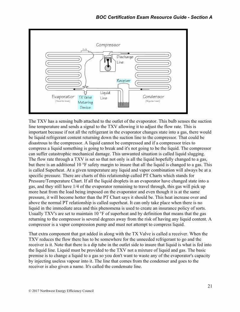
The TXV has a sensing bulb attached to the outlet of the evaporator. This bulb senses the suction line temperature and sends a signal to the TXV allowing it to adjust the flow rate. This is important because if not all the refrigerant in the evaporator changes state into a gas, there would be liquid refrigerant content returning down the suction line to the compressor. That could be disastrous to the compressor. A liquid cannot be compressed and if a compressor tries to compress a liquid something is going to break and it's not going to be the liquid. The compressor can suffer catastrophic mechanical damage. This unwanted situation is called liquid slugging. The flow rate through a TXV is set so that not only is all the liquid hopefully changed to a gas, but there is an additional 10 °F safety margin to insure that all the liquid is changed to a gas. This is called Superheat. At a given temperature any liquid and vapor combination will always be at a specific pressure. There are charts of this relationship called PT Charts which stands for Pressure/Temperature Chart. If all the liquid droplets in an evaporator have changed state into a gas, and they still have 1/4 of the evaporator remaining to travel through, this gas will pick up more heat from the load being imposed on the evaporator and even though it is at the same pressure, it will become hotter than the PT Chart says it should be. This heat increase over and above the normal PT relationship is called superheat. It can only take place when there is no liquid in the immediate area and this phenomena is used to create an insurance policy of sorts. Usually TXV's are set to maintain 10 °F of superheat and by definition that means that the gas returning to the compressor is several degrees away from the risk of having any liquid content. A compressor is a vapor compression pump and must not attempt to compress liquid.
That extra component that got added in along with the TX Valve is called a receiver. When the TXV reduces the flow there has to be somewhere for the unneeded refrigerant to go and the receiver is it. Note that there is a dip tube in the outlet side to insure that liquid is what is fed into the liquid line. Liquid must be provided to the TXV not a mixture of liquid and gas. The basic premise is to change a liquid to a gas so you don't want to waste any of the evaporator's capacity by injecting useless vapour into it. The line that comes from the condenser and goes to the receiver is also given a name. It's called the condensate line.

BOC Certification Exam Resource Guide - Section A
22 © 2017 Northwest Energy Efficiency Council
Refrigeration Compressors http://www.globalspec.com/learnmore/building_construction/hvac/ventilation/refrigeration_compressors_air_conditioning_compressors; IHS (Global Spec) Engineering 360, 2015 HIS
Refrigeration compressors and air conditioning compressors provide air conditioning, heat pumping, and refrigeration for large-scale facilities and equipment. They use compression to raise the temperature of a low-pressure gas, and also remove vapor from the evaporator. Most refrigeration compressors (refrigerant compressors) are large, mechanical units that form the heart of industrial cooling, heating, ventilation, and air conditioning (HVAC) systems. Many air conditioning compressors are also large-scale mechanical devices; however, these compressors are designed specifically for air conditioning systems and do not provide heating or ventilation functions.
Refrigerant compressors work by taking in low pressure gas on the inlet and compressing it mechanically. Different types of compression mechanisms are what differentiate compressors (discussed below). This compression creates a high temperature, high pressure gas - an essential step in the overarching refrigeration cycle.
Review refrigeration cycle video at the URL: http://www.globalspec.com/learnmore/building_construction/hvac/ventilation/refrigeration_compressors_air_conditioning_compressors
Typical HVAC Refrigerants http://inspectapedia.com/aircond/Refrigerant_Pressures.htm Daniel Friedman on InspectAPedia® 2015
See Refrigerant Pressure-Temp Chart PDF in Appendix.
STUDY QUESTIONS: What are the Typical Air Conditioner or Heat Pump System Pressures During Normal Operation?
______________________________________________________________________
What is a “charging chart” used for?
______________________________________________________________________
Be able to read a charging chart. In the example below, what is the recommended output pressure given an outside air temp of 85 F? See Refrigerant Pressure-Temp Chart PDF in Appendix.
Example actual air conditioner compressor high side output pressure: using R-22 refrigerant and assuming an outside air temperature of 85 degF called for 120 degF. inside the compressor (add 35 degF. to incoming air temperature) and an output high-side compressor pressure of about 260 psi.
BOC Certification Exam Resource Guide - Section A
23 © 2017 Northwest Energy Efficiency Council
Measuring the refrigerant pressure in air conditioning, heat pump or other refrigerant systems can diagnose a range of operating problems including a refrigerant leak, over charging or under charging.
Refrigerant pressure readings measured at the air conditioning compressor/condenser unit and which are found to be too low on the high pressure side (compressor output) or on the low pressure side (compressor input or suction line) can indicate a problem with the compressor's ability to develop normal operating pressure ranges and thus will affect the cooling capacity of the air conditioning system.
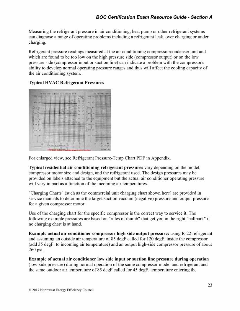
Typical HVAC Refrigerant Pressures
For enlarged view, see Refrigerant Pressure-Temp Chart PDF in Appendix.
Typical residential air conditioning refrigerant pressures vary depending on the model, compressor motor size and design, and the refrigerant used. The design pressures may be provided on labels attached to the equipment but the actual air conditioner operating pressure will vary in part as a function of the incoming air temperatures.
"Charging Charts" (such as the commercial unit charging chart shown here) are provided in service manuals to determine the target suction vacuum (negative) pressure and output pressure for a given compressor motor.
Use of the charging chart for the specific compressor is the correct way to service it. The following example pressures are based on "rules of thumb" that get you in the right "ballpark" if no charging chart is at hand.
Example actual air conditioner compressor high side output pressure: using R-22 refrigerant and assuming an outside air temperature of 85 degF called for 120 degF. inside the compressor (add 35 degF. to incoming air temperature) and an output high-side compressor pressure of about 260 psi.
Example of actual air conditioner low side input or suction line pressure during operation (low-side pressure) during normal operation of the same compressor model and refrigerant and the same outdoor air temperature of 85 degF called for 45 degF. temperature entering the
BOC Certification Exam Resource Guide - Section A
24 © 2017 Northwest Energy Efficiency Council
compressor (subtract 40 degF. from incoming air temperature) which on the service chart indicates that the incoming or suction line pressure would be about 75 psi.
Example of a more theoretical air conditioner or heat pump pressure and temperature at the compressor and at the cap tube or thermostatic expansion valve during normal operation: at an outdoor temperature of 72 degF, liquid refrigerant (R12 for example) leaving the outdoor condensing coil and entering the cap tube or TEV might be at 100 psi and 95 degF.
These numbers vary by changes in ambient temperature, compressor model, and refrigerant gas used. On the low side of the TEV or cap tube (in the cooling coil in the air handler) where the liquid refrigerant is changing state to a gas, it may be cooled down to 10 degF. and by the time the refrigerant leaves the cooing coil (evaporator coil) and gets back to the compressor motor it will be all vapor and may be at just 15 psi. [R12 refrigerant changes from liquid to vapor at 14.6 psi at 10 degF.
Evaporators & Refrigeration Systems https://quizlet.com/4050009/evaporators-and-the-refrigeration-system-flash-cards/
2015 Quizlet Inc.
STUDY QUESTIONS: What is the function of the evaporator?
______________________________________________________________________
The refrigerant in the evaporator changes from __________ to ___________?
______________________________________________________________________
The heat that is added to a vapor after all the liquid has boiled away is referred to as?
______________________________________________________________________
What determines the pressure on the low side of the system?
______________________________________________________________________
What is typical superheat for a evaporator?
______________________________________________________________________
What does a high superheat indicate?
______________________________________________________________________
What does a low evaporator superheat indicate?
______________________________________________________________________
BOC Certification Exam Resource Guide - Section A
25 © 2017 Northwest Energy Efficiency Council
Why are multi-circuit evaporators used?
______________________________________________________________________
What type of expansion devices do flooded evaporators use?
______________________________________________________________________
Dry-type evaporators are also called _______________?
What happens when an evaporator experiences a heat load increase?
______________________________________________________________________
Suction Line Accumulator http://www.parker.com/literature/Aftermarket%20AC%20and%20Refrigeration%20Division/Catalogs/PDF%20fies/Catalog%20C-1%20Accumulators.pdf
Catalog C-1, 10/2007; Hannifin Parker Corporation
STUDY QUESTIONS: What is the function of an accumulator and a receiver?
______________________________________________________________________
What are typical maintenance requirements for an accumulator?
______________________________________________________________________
What considerations should be given to the use of new refrigerants in an accumulator?
______________________________________________________________________
What is slugging?
______________________________________________________________________
Design
The function of a suction line accumulator in a heat pump or refrigeration system is to catch and hold any unused portion of the system charge. The device must also prevent liquid slugging of the compressor and excessive refrigerant dilution of the compressor oil. The accumulator must return refrigerant and oil to the compressor at a sufficient rate to maintain both system operating efficiency and proper crankcase oil level. To make sure these tasks are accomplished, system designers must consider the following items:
• A properly sized and protected oil return orifice is required to ensure positive oil (and refrigerant) return to the compressor
• The accumulator must have sufficient internal volume
BOC Certification Exam Resource Guide - Section A
26 © 2017 Northwest Energy Efficiency Council
• The pressure drop across the accumulator should be as low as possible
Oil return at a minimum flow rate is controlled by the outlet U-tube size. Refrigerant and oil will be returned to the compressor by pressure drop across the orifice metering area and the liquid head above the orifice. Other design requirements include safe working pressure, agency approvals and corrosion resistance. Figure 1 (see URL above) illustrates a typical accumulator with an inlet defector. The shape of the deflector directs the inlet flow in a slightly downward tangential direction. The inlet to the U-tube is located behind the inlet deflector to prevent liquid carry-over and is bell-shaped to reduce the sudden contraction loss of the high velocity gas. The U-tube diameter is selected to minimize pressure drop at high flow rates yet provide adequate oil return at low flow rates. Other features include a 50 x 60 mesh screen to protect the oil return orifice, an anti-siphon hole and a fusible alloy plug in the accumulator. The anti-siphon hole located near the outlet of the U-tube prevents liquid from siphoning into the outlet tube and compressor during an off-cycle. The fusible alloy plug is generally a U.L. requirement since it is a safety device to protect against excessive pressure in the event of a fire.
Selection
Accumulator selection can be fine-tuned for best performance. This involves the sizing of the accumulator and the sizing of the orifice. The controlling factor for both types is the type of metering device used in the system. In systems using a fixed orifice, the accumulator holding capacity should be about 70% of the system charge. This provides adequate holding capacity during operation with blocked or fouled heat exchanger coils. The resulting high discharge/low suction pressure condition will result in more liquid refrigerant in the accumulator. The oil return orifice size should be small to prevent excess liquid refrigerant being returned to the compressor. For these systems, a 0.040 inch (1.02 mm) diameter orifice is the recommended starting point. Systems with a thermostatic expansion valve (TEV), the accumulator holding capacity should be approximately 50% of the system charge. At startup and after defrost the bulb of the TEV is warm. Until the valve regains control, the accumulator plays a role in preventing liquid slugging of the compressor. The accumulator must also contend with off cycle refrigerant migration. At shut-down, the accumulator is the coldest component in the system. This results in migration of liquid refrigerant to the device. This type of system needs to return the refrigerant to circulation more quickly than the fixed orifice system. For these systems, a 0.055 inch (1.4 mm) diameter orifice allows quick return of the liquid refrigerant. The recommended sizes of the orifices can be further tested for optimum results. Other size orifices are possible to satisfy the characteristics required by the system designer.
New Refrigerants
The introduction of alternative refrigerants and oils requires reviewing the design of components within the system, including suction accumulators. As previously stated, the accumulator is the coldest component in the system. The new refrigerants and oils may or may not be fully miscible (e.g., mixable in a homogeneous form) in the temperature range the accumulator normally operates. The oil and refrigerant can separate into oil rich and refrigerant rich layers

BOC Certification Exam Resource Guide - Section A
27 © 2017 Northwest Energy Efficiency Council
in the accumulator, with the refrigerant rich layer at the bottom. The oil return orifice would be located in the refrigerant rich layer. The solution to this problem is to provide active mixing of the layers in the accumulator. This is accomplished by the shape and position of the inlet deflector and outlet U-tube. The inlet flow stream is directed tangentially into the liquid layers in the bottom of the accumulator. The resulting circulation of the liquid past the off center U-tube forces a mixing of the oil and refrigerant layers.
Field Replacement
The accumulator should be changed when a compressor is replaced. The old accumulator may contain contaminants from the problem that caused the compressor failure. There may also be considerable oil remaining from the first compressor if a gradual loss of refrigerant caused the failure. This amount coupled with the oil in the replacement compressor may create an oil overcharge condition.
Liquid Receiver http://www.answers.com/Q/What_is_the_function_of_liquid_receiver_in_a_refrigeration_system
STUDY QUESTION: What is the Function of Liquid Receiver in a Refrigeration System?
______________________________________________________________________
Liquid receivers are used to store the liquid refrigerant after it leaves the condenser. It should be located below the condenser to enable natural flow. The receiver may be constructed either vertically or horizontally and should have sufficient capacity to hold the entire system's refrigerant charge. The design should be such that only liquid refrigerant leaves the receiver and enters the liquid line.
Vacuum Evaporation http://en.wikipedia.org/wiki/Vacuum_evaporation Wikipedia, last modified 2/15/2015
Vacuum evaporation is the process of causing the pressure in a liquid-filled container to be reduced below the vapor pressure of the liquid, causing the liquid to evaporate at a lower temperature than normal. Although the process can be applied to any type of liquid at any vapor pressure, it is generally used to describe the boiling of water by lowering the container's internal pressure below standard atmospheric pressure and causing the water to boil at room temperature.
The vacuum evaporation treatment process consists of reducing the interior pressure of the evaporation chamber below atmospheric pressure. This reduces the boiling point of the liquid to be evaporated, thereby reducing or eliminating the need for heat in both the boiling and condensation processes. In addition, there are other technical advantages such as the ability to distill other liquids with high boiling points and avoiding the decomposition of substances that are sensitive to temperature, etc.[1]
BOC Certification Exam Resource Guide - Section A
28 © 2017 Northwest Energy Efficiency Council
Electrical Systems
STUDY QUESTIONS: In the US, the National Electrical Code only mandates colors for two components in an AC power system. What are they? What colors are mandated for each?
_____________________________________________________________________
What is the difference between an insulator and a conductor in an electrical system?
______________________________________________________________________
What is the function of a capacitor?
Wiring a 2-way Switch by Gary Mayo on How To Wire It.com - 2008-2015©
Go to the URL to review how a 2-way switch circuit works, and be prepared to answer a question about it. http://www.how-to-wire-it.com/wiring-a-2-way-switch.html
Wiring Color Codes http://www.allaboutcircuits.com/vol_5/chpt_2/2.html; Wiring Color Codes; US, AC; US National Electrical Code; All About Circuits 2015
Wiring for AC and DC power distribution branch circuits are color coded for identification of individual wires. In some jurisdictions all wire colors are specified in legal documents. In other jurisdictions, only a few conductor colors are so codified. In that case, local custom dictates the “optional” wire colors.
IEC, AC: Most of Europe abides by IEC (International Electrotechnical Commission) wiring color codes for AC branch circuits. These are listed in Table below. The older color codes in the table reflect the previous style which did not account for proper phase rotation. The protective ground wire (listed as green-yellow) is green with yellow stripe.
US, AC: The US National Electrical Code only mandates white (or grey) for the neutral power conductor and bare copper, green, or green with yellow stripe for the protective ground. In principle any other colors except these may be used for the power conductors. The colors adopted as local practice are shown in Table below. Black, red, and blue are used for 208 VAC three-phase; brown, orange and yellow are used for 480 VAC. Conductors larger than #6 AWG are only available in black and are color taped at the ends.
BOC Certification Exam Resource Guide - Section A
29 © 2017 Northwest Energy Efficiency Council
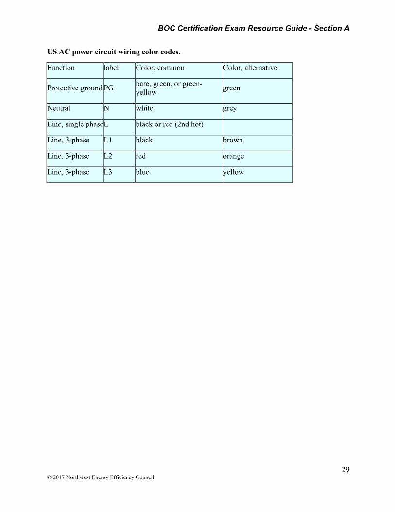
US AC power circuit wiring color codes.
Function label Color, common Color, alternative
Protective ground PG bare, green, or green-yellow green
Neutral N white grey
Line, single phase L black or red (2nd hot)
Line, 3-phase L1 black brown
Line, 3-phase L2 red orange
Line, 3-phase L3 blue yellow
BOC Certification Exam Resource Guide - Section A
30 © 2017 Northwest Energy Efficiency Council
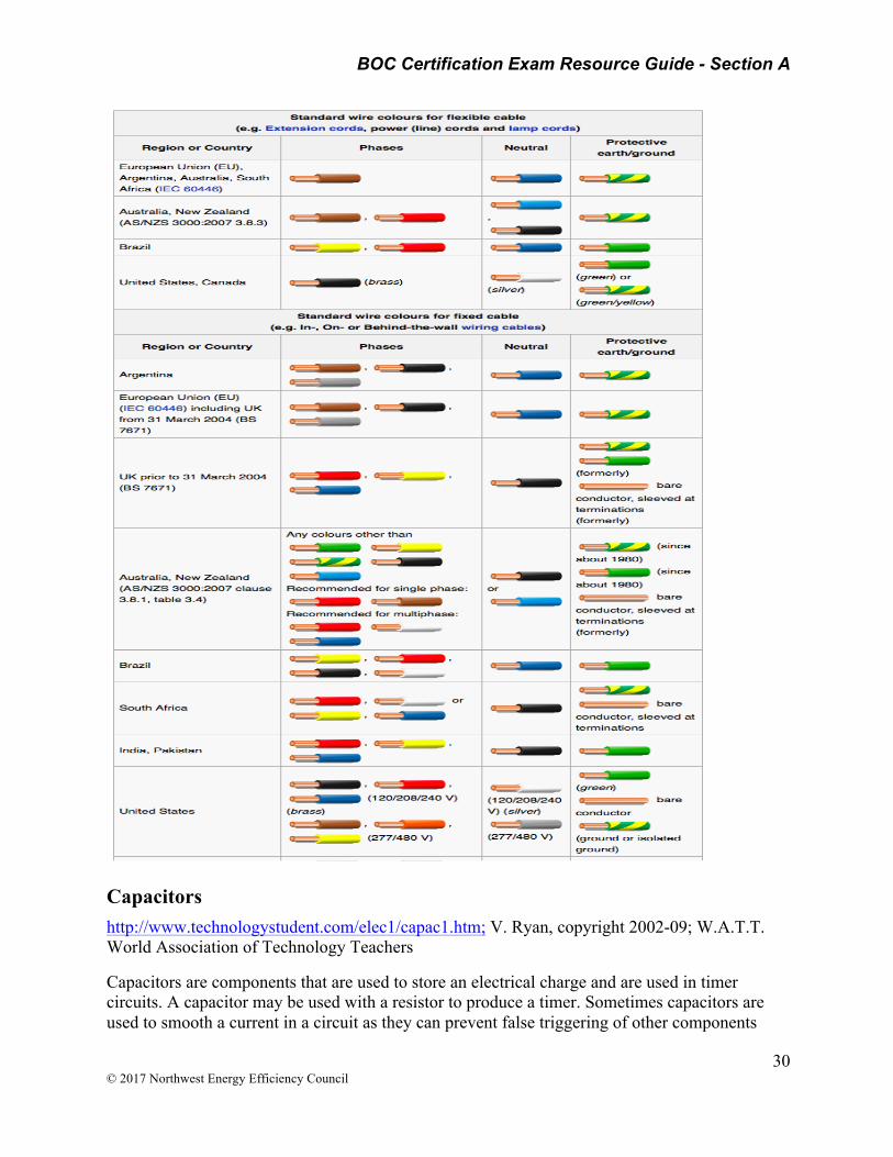
Capacitors http://www.technologystudent.com/elec1/capac1.htm; V. Ryan, copyright 2002-09; W.A.T.T. World Association of Technology Teachers
Capacitors are components that are used to store an electrical charge and are used in timer circuits. A capacitor may be used with a resistor to produce a timer. Sometimes capacitors are used to smooth a current in a circuit as they can prevent false triggering of other components
BOC Certification Exam Resource Guide - Section A
31 © 2017 Northwest Energy Efficiency Council
such as relays. When power is supplied to a circuit that includes a capacitor, the capacitor charges up. When power is turned off the capacitor discharges its electrical charge slowly.
HOW A CAPACITOR WORKS
When the circuit is switched on, the LED emits light and the capacitor charges up. When the switch is turned off the LED stills emits a light for a few seconds because the electricity stored in the capacitor is slowly discharged. When it has fully discharged its electricity, the LED no longer emits light. If a resistor is introduced to the circuit the capacitor charges up more slowly but also discharges more slowly. What will happen to the light?
Electrolytic capacitors are ‘polarised’ which means they have a positive and negative lead and must be positioned in a circuit the right way round (the positive lead must go to the positive side of the circuit). They also have a much higher capacitance than non-electrolytic capacitors. Non-electrolytic capacitors usually have a lower capacitance. They are not polarised (do not have a positive and negative lead) and can be placed anyway round in a circuit. They are normally used to smooth a current in a circuit. CAPACITANCE - means the value of a capacitor.
Electrical Insulation http://global.kyocera.com/fcworld/charact/elect/insulation.html Fine Ceramics World, Kyocera Corporation
Electrical Insulation is a material that is unable to conduct electricity due to its high level of electrical resistance is an insulator. In contrast, a conductor is a material that offers low resistance to electric conductivity. An atom, the smallest unit of matter, is composed of a nucleus and electrons which orbit that nucleus. Whether a substance is an insulator or a conductor generally depends on the number of free electrons it possesses, which can be used to carry electric current. A substance with higher insulation properties is less conductive because it possesses fewer free electrons.
Generally, Fine Ceramics (also known as “advanced ceramics”) are insulating materials that do not conduct electricity. A few examples of products that utilize the insulation property of Fine Ceramics include packages for surface-mounted electronic components, such as quartz crystal oscillators and surface acoustic wave (SAW) filters. These products are widely used in mobile phones, automotive navigation systems and portable music players. Ceramic packages provide advanced hermetic sealing and electrical insulation between electric circuit lines to maintain the high reliability of these electronic components.
In addition to Fine Ceramics, other insulators include paraffin, rubber, plastic, paper and marble. Because ceramics are fired in a kiln, they can be fashioned into a wide variety of shapes with excellent heat resistance and durability. For these reasons, ceramics have long been used as insulators.

BOC Certification Exam Resource Guide - Section A
32 © 2017 Northwest Energy Efficiency Council
Area 2 - Troubleshoot system & equipment problems & perform diagnostic testing
Compressed Air Systems O&M Best Practices Guide, Release 3.0
https://energy.gov/sites/prod/files/2013/10/f3/omguide_complete.pdf
STUDY QUESTIONS: What is the function of a flow controller in a compressed air system?
______________________________________________________________________
How does a flow controller reduce air leakage in a compressed air system?
______________________________________________________________________
Where would you look for leaks in a typical compressed air system?
______________________________________________________________________
The average compressed air system wastes between ____________ to leaks.
9.11.5.3 Use of Flow Controllers
Most compressed air systems operate at artificially high pressures to compensate for flow fluctuations and downstream pressure drops caused by lack of “real” storage and improperly designed piping systems. Even if additional compressor capacity is available, the time delay caused by bringing the necessary compressor(s) on-line would cause unacceptable pressure drop.
Operating at these artificially high pressures requires up to 25% more compressor capacity than actually needed. This 25% in wasted operating cost can be eliminated by reduced leakage and elimination of artificial demand.
A flow controller separates the supply side (compressors, dryers, and filters) from the demand side (distribution system). It creates “real” storage within the receiver tank(s) by accumulating compressed air without delivering it downstream. The air pressure only increases upstream of the air receiver, while the flow controller delivers the needed flow downstream at a constant, lower
BOC Certification Exam Resource Guide - Section A
33 © 2017 Northwest Energy Efficiency Council
system pressure. This reduces the actual flow demand by virtually eliminating artificial demand and substantially reducing leakage.
9.11.5.4 Importance of Maintenance to Energy Savings
• Leaks are expensive. Statistics show that the average system wastes between 25% and 35% to leaks. In a compressed air system of 1,000 cfm, 30% leaks equals 300 cfm. That translates into savings of 60 hp or $45,000 annually.
• A formalized program of leak monitoring and repair is essential to control costs. As a start, monitor all the flow needed during off periods.
• Equip maintenance personnel with proper leak detection equipment and train them on how to use it. Establish a routine for regular leak inspections. Involve both maintenance and production personnel.
• Establish accountability of air usage as part of the production expense. Use flow controllers and sequencers to reduce system pressure and compressed air consumption.
• A well-maintained compressor not only serves you better with less downtime and repairs, but will save you electrical power costs too.
9.11.5.5 Leak Evaluation Procedure
Leaks can be a significant source of wasted energy in an industrial compressed air system, sometimes wasting 20 to 30% of a compressor’s output. A typical plant that has not been well maintained will likely have a leak rate equal to 20 percent of total compressed air production capacity. On the other hand, proactive leak detection and repair can reduce leaks to less than 10 percent of compressor output (DOE 1998, UNEP 2006).
In addition to being a source of wasted energy, leaks can also contribute to other operating losses. Leaks cause a drop in system pressure, which can make air tools function less efficiently, adversely affecting production. In addition, by forcing the equipment to run longer, leaks shorten the life of almost all system equipment (including the compressor package itself). Increased running time can also lead to additional maintenance requirements and increased unscheduled downtime. Finally, leaks can lead to adding unnecessary compressor capacity.
While leakage can come from any part of the system, the most common problem areas are:
• Couplings, hoses, tubes, and fittings • Pressure regulators • Open condensate traps and shut-off valves • Pipe joints, disconnects, and thread sealants.
Leakage rates are a function of the supply pressure and increase with higher system pressures.
For compressors that have start/stop or load/unload controls, there is an easy way to estimate the amount of leakage in the system. This method involves starting the compressor when there are no demands on the system (when all the air-operated, end-use equipment is turned off). A number of measurements are taken to determine the average time it takes to load and unload the
BOC Certification Exam Resource Guide - Section A
34 © 2017 Northwest Energy Efficiency Council
compressor. The compressor will load and unload because the air leaks will cause the compressor to cycle on and off as the pressure drops from air escaping through the leaks.
Total leakage (percentage) can be calculated as follows (DOE 1998):
Leakage Percentage (%) = {(T x 100)/(T + t)}
where: T = on-loading time in minutes
t = off-loading time in minutes
Leakage will be expressed in terms of the percentage of compressor capacity lost. The percentage lost to leakage should be less than 10 percent in a well-maintained system. Poorly maintained systems can have losses as high as 20 to 30 percent of air capacity and power.
Find & Fix Compressed Air Leaks Compressed Air Best Practices 05-06/10, Finding and Fixing Leaks by Ron Marshall, PDC Committee Member, Compressed Air Challenge®
http://www.compressedairchallenge.org/library/articles/2010-05-CARP.pdf
Read and answer questions.
STUDY QUESTIONS: What is the acceptable percent lost to leakage in a well-maintained system?
______________________________________________________________________
What are examples of diagnostic tools for finding compressed air leaks?
______________________________________________________________________
Pneumatic Tips – A Design World Resource, posted by Paul Heney, 4/25/2013, Finding and Fixing Compressed Air Leaks
http://www.pneumatictips.com/2881/2013/04/air-preparation/finding-and-fixing-compressed-air-leaks/
Leaks can be a significant source of wasted energy in an industrial compressed air system, sometimes wasting 20-30% of a compressor’s output. A typical plant that has not been well maintained will likely have a leak rate equal to 30% of total compressed air production capacity or higher. On the other hand, proactive leak detection and repair can reduce leaks to less than 10%. Leakage will be expressed in terms of the percentage of compressor capacity lost. The percentage lost to leakage should be less than 10% in a well-maintained system. Poorly maintained systems can have losses as high as 20–30% of air capacity and power.
BOC Certification Exam Resource Guide - Section A
35 © 2017 Northwest Energy Efficiency Council
In addition to wasting energy, leaks can also contribute to other operating losses. Leaks cause a drop in system pressure, which can make air tools function less efficiently, adversely affecting production. In addition, by forcing the equipment to cycle more frequently, leaks shorten the life of almost all system equipment (including the compressor package itself). Increased running time can also lead to additional maintenance requirements and increased unscheduled downtime. Finally, leaks can lead to adding unnecessary compressor capacity.
How to fix leaks Leaks occur most often at joints and connections at end-use applications. Stopping leaks can be as simple as tightening a connection or as complex as replacing faulty equipment such as couplings, fittings, pipe sections, hoses, joints, drains, and traps. In many cases leaks are caused by bad or improperly applied thread sealant. Select high quality fittings, disconnects, hose, tubing, and install them properly with appropriate thread sealant.
Non-operating equipment can be an additional source of leaks. Equipment no longer in use should be isolated with a valve in the distribution system.
Establishing a leak prevention program A good leak prevention program will include the following components: identification (including tagging), tracking, repair, verification, and employee involvement. All facilities with compressed air systems should establish an aggressive leak reduction program. A cross-cutting team involving decision-making representatives from production should be formed.
A good compressed air system leak repair program is very important in maintaining the efficiency, reliability, stability and cost effectiveness of any compressed air system.
Water Systems
Water Leaks – Leaky Faucets http://www.in.gov/oucc/2394.htm#1 Make Sure Your Home or Business is Leak-Free, 1. Example 2
STUDY QUESTION: A water leak can increase the building owner’s water bill based on the number of gallons wasted from the leak. What impact can a water leak have on the owner’s sewage bill? ______________________________________________________________________
Check all faucets to make sure they do not leak or drip.
• A faucet that drips once per second and goes unrepaired for a month wastes nearly 260 gallons of water.
• If the same faucet goes unrepaired for a year, the wasted water will add up to more than 3,100 gallons.
o Example 1: If a customer is billed at a rate of $1.75 per 1,000 gallons, a 3,100 gallon leak will add $5.43 to the customer’s bills.

BOC Certification Exam Resource Guide - Section A
36 © 2017 Northwest Energy Efficiency Council
o Example 2: For the customer who is billed $7.00 per 1,000 gallons, the same leak would cost $21.70. (Such a leak would also increase the customer’s sewage bill, if it is also calculated on the amount of water used.)
• A faucet that drips once every 3 seconds wastes 86 gallons of water per month. o A typical home uses approximately 5,000 gallons of water per month.
Leaky faucets can be fixed inexpensively. Hardware stores, plumbing supply stores and home maintenance books can help.
HVAC Systems
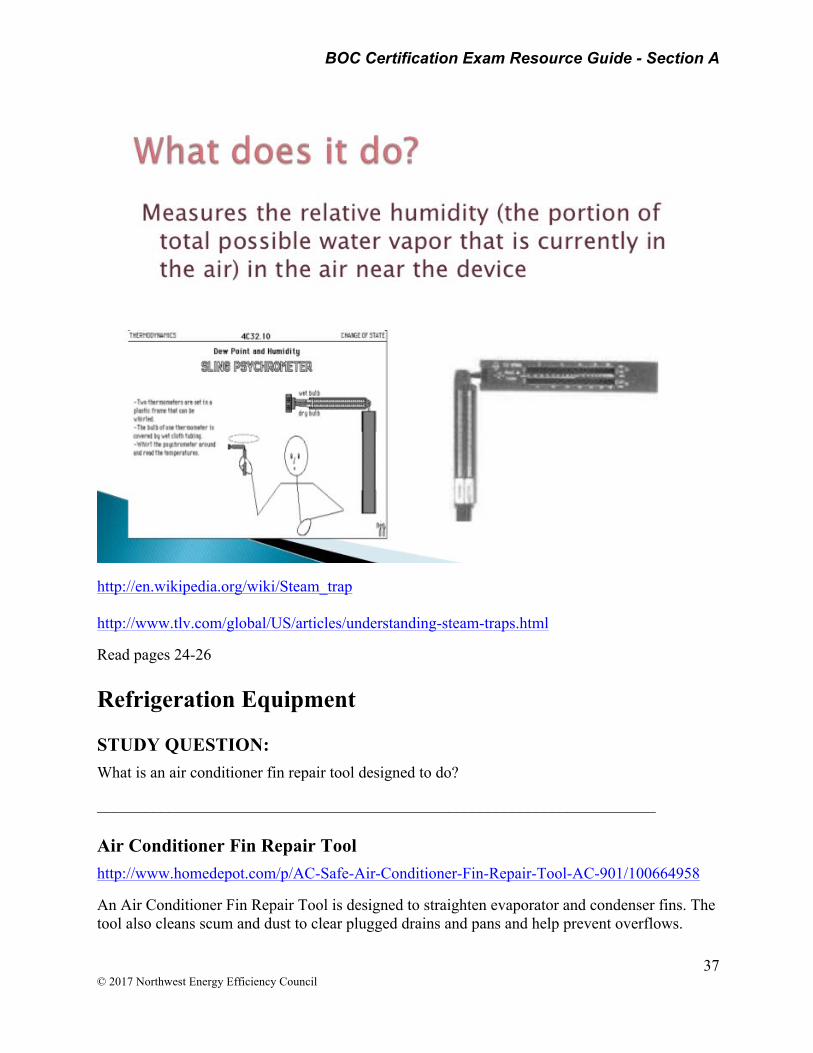
Sling psychrometer A sling psychrometer holds a wet-bulb thermometer and a dry-bulb thermometer. A dry-bulb thermometer is an ordinary thermometer, while a wet-bulb thermometer is a thermometer that has its bulb wrapped in cloth and moistened with distilled water.
When a sling psychrometer is swung round in the air, moisture will evaporate from the wet-bulb thermometer, reducing its temperature depending on the humidity of the air it is exposed to. The higher the humidity, the lower the rate of evaporation and so the higher the temperature recorded. Wet-bulb temperatures are the same as dry-bulb temperatures at a relative humidity of 100%, but otherwise will be lower than dry-bulb temperatures due to the cooling effect of evaporation (described as wet-bulb depression).
The two thermometers should give steady-state readings after a few minutes.
A sling psychrometer can be used to determine the physical and thermal properties of moist air by using standard tables and charts. Typically it is used to determine relative humidity. Some sling psychrometers include mechanisms to allow relative humidity to be read directly without needing to refer to tables.
Psychometric charts are complex graphs that represent the dry-bulb temperature, wet-bulb temperature, relative humidity, specific volume, dew point temperature, humidity ratio and enthalpy of moist air at known atmospheric pressure. The state of moist air can be determined from any two of these properties (such as wet-bulb temperature and dry-bulb temperature which can be read on a sling psychrometer) from which all other properties can then be determined.
BOC Certification Exam Resource Guide - Section A
37 © 2017 Northwest Energy Efficiency Council
http://en.wikipedia.org/wiki/Steam_trap http://www.tlv.com/global/US/articles/understanding-steam-traps.html
Read pages 24-26
Refrigeration Equipment
STUDY QUESTION: What is an air conditioner fin repair tool designed to do?
______________________________________________________________________
Air Conditioner Fin Repair Tool http://www.homedepot.com/p/AC-Safe-Air-Conditioner-Fin-Repair-Tool-AC-901/100664958
An Air Conditioner Fin Repair Tool is designed to straighten evaporator and condenser fins. The tool also cleans scum and dust to clear plugged drains and pans and help prevent overflows.

BOC Certification Exam Resource Guide - Section A
38 © 2017 Northwest Energy Efficiency Council
• Straightens condenser and evaporator fins • Cleans accumulated scum and dust • Helps to prevent overflows by eliminating plugged drains and pans • Promotes optimal cooling efficiency • Suitable for use with central and window units • Fits most fin sizes and styles • Tubular aluminum body • Fixed steel lines
Economizer and Mixed Air http://www.ftguide.org/ftg/SystemModules/AirHandlers/AHU_ReferenceGuide/FTG_Chapters/Chapter_3_Economizer_and_Mixed_Air.htm NOTE: This is a large section of reading material.
STUDY QUESTIONS: What two conditions could lead to economizer control loop instability?
______________________________________________________________________
Identify one symptom that could result from poor mixing of outside and return air in an air handling unit?
_____________________________________________________________________
What negative effect does excessive outside air have on the HVAC system?
______________________________________________________________________
Building Envelope
STUDY QUESTIONS: What conditions in the building structure affect air leakage?
______________________________________________________________________
What is the stack effect in a building?
______________________________________________________________________
What steps would you take to reduce infiltration due to stack effect?
______________________________________________________________________
What standards specify maintenance of fire smoke system damper and actuators?
______________________________________________________________________

BOC Certification Exam Resource Guide - Section A
39 © 2017 Northwest Energy Efficiency Council
Reducing Air Leaks - Infiltration & Exfiltration http://www.fmlink.com/article.cgi?type=How%20To&title=Reducing%20Infiltration%20and%20Exfiltration&pub=BOMI%20International&id=42413&mode=source
When air leaks into your facility from outside, you have infiltration; when conditioned indoor air leaks out, it’s exfiltration. Both can occur through cracks around windows, doors, dampers, and skylights, or whenever a door or window is opened. The amount of infiltration and exfiltration that occurs is obviously affected by the types of openings your building has along with how good your weatherproofing is, but there are other factors as well. The building’s structure, the direction and duration of the wind, and pressure differences inside and outside the building also affect air leakage.
Pressure. If buildings are designed to minimize changes in air pressure, then the problems and costs associated with infiltration and exfiltration are minimized. For example, an L- or U-shaped building whose center is oriented away from prevailing wind will experience minimal infiltration and exfiltration because those winds are not trapped within the building structure.
The building plan also influences the amount of infiltration and exfiltration. Having fewer doors and windows reduces infiltration, as does using vestibules and wind barriers in front of those entrances subject to high wind velocities.
Infiltration increases as wind velocity increases. In most parts of the northern hemisphere, northern or western sides of a building are exposed to the wind during winter months. The average wind velocity in winter is 10 to 15 miles per hour. In some locations, however, it is considerably higher. In high winds, a negative pressure is often created on the side of a building opposite the wind (referred to as the leeward side). If a building’s northern and western exposures are windowless and/or tight, this negative pressure may force air into the building through openings in the lee side.
The Stack Effect. Pressure differences are created by a building’s air handling system, the wind, and temperature variations. As warm, low-pressure air rises through a building, it tends to draw with it the cooler, high-pressure air from lower levels. This phenomenon, called the stack effect, increases infiltration and is a significant concern when designing heating systems for tall buildings in cold climates. The height of the building and the penetrability between floors determine the impact stack effect may have.
In high-rise buildings with operable windows, stack effect can increase infiltration on lower levels of the leeward side and increase exfiltration on upper levels of the windward side when high winds and low temperatures occur. Even in pressurized buildings with sealed windows and revolving doors, stack effect may cause heat loss or heat gain through elevator shafts or stair towers.
In tall buildings, the stack effect resulting from indoor and outdoor temperature differences also causes air to leak through cracks and openings. Stack effect is always a potential problem for vertical spaces such as service shafts, elevator shafts, and staircases. The density difference between the warm air in the shaft and cold outdoor air causes air to leak into the bottom of the shaft and out the top.

BOC Certification Exam Resource Guide - Section A
40 © 2017 Northwest Energy Efficiency Council
Implement the following procedures to reduce infiltration due to stack effect:
• In winter, reduce temperatures in stairwells. If necessary, protect piping from freezing. • Seal elevator shafts at the top and bottom. Be sure that penthouse machine room doors
are weather-stripped and kept closed. • Seal vertical service shafts at the top and bottom and, in tall buildings, on every sixth
floor. • Weather-strip doors to basement and rooftop equipment rooms when they are connected
by a vertical shaft that serves the building, and keep the doors closed. • Comply with building code venting requirements. Check the fire-resistance rating of
materials used. Skylights or smoke relief vents may be required. • Inspection Guidelines: Use the following guidelines when inspecting doors, windows,
skylights, and other exterior surfaces for infiltration and exfiltration. • Windows and skylights • Replace broken or cracked windowpanes. • Weather-strip the operable sash if cracks are evident. • Caulk around window frames (exterior and interior) if cracks are evident. • Repair windows. Be certain that all windows have sealing gaskets and cam latches that
are in proper working order. • Rehang misaligned windows. • Doors • Install weather stripping if none has been installed. • Replace any worn or broken weather stripping. • Rehang misaligned door frames. • Inspect all automatic doors to ensure that they are functioning properly. Consider
adjusting doors to close faster. • Inspect gasket on garage and other overhead doors. Repair, replace, or install gaskets as
necessary. • Exterior Surfaces • Caulk, weather-strip, or install gaskets on all exterior joints, such as those between wall
and foundation or wall and roof, as well as those between wall panels. • Caulk, weather-strip, or install gaskets on all openings used for electrical conduits,
piping, through-the-wall cooling, outdoor air louvers, and the like. • Where practical, cover window air conditioners and through-the-wall cooling units when
not in use. Specifically designed covers can be obtained at relatively low cost.
This article is adapted from the BOMI International course Energy Management and Controls. More information regarding this course is available by calling 1-800-235-2664. Visit BOMI International’s website, www.bomi.org.
Fire Smoke System Damper and Actuator Maintenance http://www.greenheck.com/media/pdf/catalogs/LSDApplSelection_catalog.pdf
BOC Certification Exam Resource Guide - Section A
41 © 2017 Northwest Energy Efficiency Council
Smoke Control Systems maintenance schedules should include, as a minimum, periodic testing and cycling of system components. Dampers and their actuator(s) must be maintained, cycled and tested as a minimum in accordance with:
• The latest editions of NFPA 80, 90A, 92, 101, and 105 • Local codes • Actuator manufacturer’s recommendations, or • Other applicable industry standards
KEY MAINTENANCE POINTS
• Fire and combination fire smoke dampers must be installed in accordance with their manufacturer’s installation instructions for the specific damper model.
• Smoke dampers centerline may be installed in ductwork within 24 in. (610 mm) of the smoke barrier they are intended to protect. Combination fire smoke dampers must be installed within and as part of, the fire rated barrier using sleeves and retaining angles, unless they are specifically tested otherwise (OFSD models).
• Required sleeve gauge or thickness depends on the damper size and the type of “duct-to-sleeve connections” used. If connections are “rigid”, the sleeve must be 16 ga. (1.5 mm) minimum (14 ga. [1.9 mm] for larger dampers). If connections are “breakaway”, the sleeve can be the same as the gauge of the connecting ductwork (see pages 9 and 10 for specific requirements).
• Factory installed combination fire smoke and smoke damper actuators are required by UL 555S.
• Maintenance of engineered life safety systems should include periodic cycling and testing of dampers and actuators in that system. Refer to industry codes and standards (such as NFPA 80, 90A, 92A, 101, and 105), as well as component manufacturers for specific recommendations.
Maintenance of Cool Roofs http://coolroofs.org/documents/EconomicFeasabilityofCleaningRoofstoMaintainReflectanceRatings_000.pdf
STUDY QUESTIONS: The loss of reflectance on a cool roof due to lack of maintenance is what?
______________________________________________________________________
What is the recommended frequency of cleaning a cool roof?
______________________________________________________________________
“Can the reflectance of the roofing be effectively restored periodically, at a maintenance cost that will be more than counterbalanced by the savings from reduced energy-use?
__________________________________________________________________
BOC Certification Exam Resource Guide - Section A
42 © 2017 Northwest Energy Efficiency Council
Is using additional insulation R-value in place of a cool roof an economical and lower maintenance route to achieve the energy savings desired?
______________________________________________________________________
Electrical Systems
Detecting Failing Electrical Connections Applications for Thermal Imagers: Loose or Corroded Electrical Connections.
http://support.fluke.com/find-sales/download/asset/2518864_a_w.pdf
2005 Fluke Corporation.
STUDY QUESTION: Why is thermal imaging a suitable technology to troubleshoot loose, over-tight or corroded connections in electrical systems?
______________________________________________________________________
The reason thermography is so applicable to the monitoring of electrical systems is that new electrical components begin to deteriorate as soon as they are installed. Whatever the loading on a circuit, vibration, fatigue and age cause the loosening of electrical connections, while environmental conditions can hasten their corroding. Briefly stated, all electrical connections will, over time, follow a path toward failure. If not found and repaired, these failing connections lead to faults. Fortunately, a loose or corroded connection increases resistance at the connection and since increased electrical resistance results in an increase in heat, a thermal image will detect the developing fault before it fails.
Detecting and correcting failing connections before a fault occurs averts fires as well as impending shutdowns that can be critical to manufacturing, commercial and institutional operations. Such predictive actions are important because when a critical system does fail, it inevitably increases costs, requires the reallocation of workers and material, reduces productivity, threatens corporate profitability and impacts the safety of employees, customers and/or clients. The following discussion focuses on using thermal imaging to troubleshoot loose, over-tight or corroded connections in electrical systems by comparing the temperatures of connections within panels.
What to check?
Check panels with the covers off and power at ideally at least 40 % of the maximum load. Measure the load, so that you can properly evaluate your measurements against normal operating conditions. Caution: only authorized and qualified personnel using the appropriate personal protective equipment (PPE) should remove electrical panel covers. Capture thermal images of all connections that have higher temperatures than other similar connections under similar loads.
BOC Certification Exam Resource Guide - Section A
43 © 2017 Northwest Energy Efficiency Council
Testing and maintaining Exit & Emergency lighting systems: Following are lighting regulations on testing and maintaining Exit & Emergency lighting systems. Read Sections 5-9 (Emergency Lighting) and 5-10 (Exit Lighting) at the URL. https://nationalfireinc.com/inspection-testing/emergency-exit-light.html
STUDY QUESTIONS: What regulations specify maintenance for exit and emergency lighting systems?
______________________________________________________________________
What are examples of standard maintenance requirements?
______________________________________________________________________
OSHA Code of Federal Regulations
• Requires adequate and reliable illumination for all exits • Requires proper maintenance to assure that exit lighting is in continuously proper
operating condition
NFPA 70 - National Electric Code
• Requires specific illumination and performance of emergency and exit lights • Provides functional standards for battery-powered emergency and exit lighting
NFPA 101 - Life Safety Code
• Requires a monthly inspection of all emergency and exit lighting systems • Requires an annual test of all emergency and exit lighting systems
International Fire Code
• Requires proper illumination of means of egress • Requires assurance that emergency and exit lighting systems will provide illumination for
at least 60 minutes
NFPA 1997 5-9.3 Periodic Testing of Emergency Lighting Equipment An annual test shall be conducted for a 1-1/2 hour duration. Equipment shall be fully functional for the duration of the test.
Standard Fire Prevention Code 1999 807.1.4 Exit Illumination and Signs A functional test shall be conducted on every required emergency lighting system at 30-day intervals for a minimum of 30-seconds.
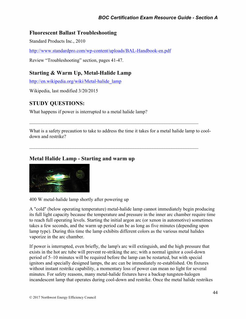
BOC Certification Exam Resource Guide - Section A
44 © 2017 Northwest Energy Efficiency Council
Fluorescent Ballast Troubleshooting Standard Products Inc., 2010
http://www.standardpro.com/wp-content/uploads/BAL-Handbook-en.pdf
Review “Troubleshooting” section, pages 41-47.
Starting & Warm Up, Metal-Halide Lamp http://en.wikipedia.org/wiki/Metal-halide_lamp
Wikipedia, last modified 3/20/2015
STUDY QUESTIONS: What happens if power is interrupted to a metal halide lamp?
______________________________________________________________________
What is a safety precaution to take to address the time it takes for a metal halide lamp to cool-down and restrike?
______________________________________________________________________
Metal Halide Lamp - Starting and warm up
400 W metal-halide lamp shortly after powering up
A "cold" (below operating temperature) metal-halide lamp cannot immediately begin producing its full light capacity because the temperature and pressure in the inner arc chamber require time to reach full operating levels. Starting the initial argon arc (or xenon in automotive) sometimes takes a few seconds, and the warm up period can be as long as five minutes (depending upon lamp type). During this time the lamp exhibits different colors as the various metal halides vaporize in the arc chamber.
If power is interrupted, even briefly, the lamp's arc will extinguish, and the high pressure that exists in the hot arc tube will prevent re-striking the arc; with a normal ignitor a cool-down period of 5–10 minutes will be required before the lamp can be restarted, but with special ignitors and specially designed lamps, the arc can be immediately re-established. On fixtures without instant restrike capability, a momentary loss of power can mean no light for several minutes. For safety reasons, many metal-halide fixtures have a backup tungsten-halogen incandescent lamp that operates during cool-down and restrike. Once the metal halide restrikes
BOC Certification Exam Resource Guide - Section A
45 © 2017 Northwest Energy Efficiency Council
and warms up, the incandescent safety light is switched off. A warm lamp also tends to take more time to reach its full brightness than a lamp that is started completely cold.
Most hanging ceiling lamps tend to be passively cooled, with a combined ballast and lamp fixture; immediately restoring power to a hot lamp before it has re-struck can make it take even longer to relight, because of power consumption and heating of the passively cooled lamp ballast that is attempting to relight the lamp.
VFD Operation & Maintenance http://www.vincentcorp.com/content/inverter-vfds-dummies; Inverter VFDs for Dummies; 4/22/2003, issue 137, Vincent Corporation
STUDY QUESTIONS: What is the purpose of a VFD?
_____________________________________________________________________
Where electrical overload protection is deemed important, what step should be taken with a VFD?
______________________________________________________________________
After installing a VFD, what steps should be taken to permanently correct a condition where the motor is running backwards?
______________________________________________________________________
Variable Frequency Drives (VFD's) are used to vary the speed of an electric motor. They do this by changing the frequency of the electric power going to the motor. They work only with three-phase power. Today they are very economical: we recently paid $500 for a 5-hp unit.
In the States, normal electric power is supplied at 60 cycles per second, sometimes called 60 hertz (Hz). At this frequency motors run at 1,800 rpm, 3,600 rpm, 1,200 rpm, or 900 rpm, depending on how they are wound. The number of poles in the winding determines its speed. For example, four-pole motors run at 1,800 rpm, and two-pole motors run 3,600 rpm. The actual motor speed, as read on the motor nameplate, is a little lower than these theoretical figures because of slippage that occurs.
The speed of the motor changes in direct proportion to the hertz. Thus, a four-pole motor running at 45 hertz will turn 1,350 rpm, and a six-pole 1200-rpm motor at 40 hertz will run 800 rpm. A motor can be sped up, also: a four-pole motor running at 90 hertz will turn 2,700 rpm.
Most VFD's come with a preset limit of 60 Hz. This can be easily changed, and Vincent usually changes it to 120 in our VFD's. This is above the recommended limit, but it is handy for short tests.
When a motor is slowed down, the cooling fan that is mounted on the motor shaft also slows down. Thus, motors have a tendency to overheat at low speeds like 10 Hz or 15 Hz. Feel the
BOC Certification Exam Resource Guide - Section A
46 © 2017 Northwest Energy Efficiency Council
motor to see that it is not overheating. A premium efficiency motor will overheat less. Low speeds are fine for a trial, but they may not be suitable for extended operation.
VFD's have a built-in circuit breaker that shuts down the motor if the amps get too high for the speed at which the motor is being run. This provides excellent (the best we know of) electrical protection for a motor and the machine it is driving.
It is best to have a VFD that is rated for more horsepower than the motor being driven. This gives more flexibility. However, where electrical overload protection is deemed important, the rating of the actual motor being driven should be loaded into the VFD. Otherwise the VFD might put out enough power, if called for, to burn up the motor.
It is very easy to install a VFD. They work only on three-phase power. So there are four wires coming from the power control panel: white, black and (usually) red power wires and a green ground wire. The three power wires are hooked to the L1, L2 and L3 terminals. There are three output terminals, labeled T1, T2 and T3 (sometimes U, V, and W), to which you connect the power wires going to the motor.
When you turn on the motor, it may be running backwards. It is usually easy to change the direction of rotation with the VFD itself. Most VFD's have a simple toggle command for forward and reverse. Unfortunately, when the motor is shut down and later restarted, it will restart running backwards again. To correct this permanently it is necessary to switch two of the power leads. It is a little tricky to change the direction of rotation of a motor with a VFD. Simply switching leads at the main circuit breaker in the motor control panel will not work. Instead, it is necessary to switch the leads coming out of the VFD, the ones going to the motor.
Vincent keeps Saftronics VFD's in the rental fleet. Saftronics was selected because of their excellent telephone assistance. Just call 1-800-533-0031, day or night, seven days a week.
Once a VFD is wired up, there may be frustration trying to get the motor to start. The solution usually is to toggle from the Remote to the Local operation, then hit the Start button.
To change the speed (frequency), get into the frequency adjustment display (next to the actual frequency output display). Toggle the speed up or down, then hit the enter button.
Amps can be read by toggling the menu button to the amps display. Amps reading are a little peculiar with VFD's. They are no longer directly in proportion to the power being consumed. So, use them as a reference only.
It is very easy to fry a VFD, and they are not worth trying to repair when you do. Be sure to have a plastic bag or sheet over the VFD. Protect the VFD from dripping pipes, rain, and wash-down water. If a loaner VFD gets cooked, we ask the customer to pay for the replacement.
VFD's are good for only one voltage, either 208-220-240 volts or 440-480 volts. Be sure you know what voltage you are working with. There are more sophisticated VFD models that work on both voltages, but Vincent does not have any of these in the rental fleet.

BOC Certification Exam Resource Guide - Section A
47 © 2017 Northwest Energy Efficiency Council
Vincent has a loaner VFD that works on household 110-volt single-phase power. Our unit transforms the voltage to 220 volts, and the power is converted from one to three phases. We put a three phase motor on the machine we are driving, usually a laboratory CP-4 press
Building Control System Maintenance
Pneumatic Controls, Controls & Features http://www.anemostat-hvac.com/literature/pneumatic_controls_desc.pdf
STUDY QUESTION: What is the purpose of a pneumatic velocity controller?
______________________________________________________________________
PNEUMATIC CONTROLS
These controls require a clean, dry source of compressed air, 20 psi being typically used. Since pneumatic controls are air consuming devices, compressor sizing should include the terminal controls. Control devices may include a velocity controller, air velocity sensor, pneumatic actuator, and volume damper. The pneumatic velocity controller is the brain which monitors pneumatic input signals from the thermostat and velocity sensor, and outputs a signal to the damper actuator resulting in air flow regulation. The pneumatic velocity sensor is mounted in the inlet of the terminal in the air stream, and provides the velocity controller with a signal proportional to actual air velocity pressure. The pneumatic damper actuator receives a pressure signal from the velocity controller in response to actual flow vs. desired flow.
THE VELOCITY CONTROLLER
The pneumatic velocity controller is a "pneumatic computer", monitoring inputs and directing outputs to maintain space temperature by controlling the flow rate of conditioned air into the space. The controller receives a pressure (psi) input signal from the thermostat (for variable air volume control), indicative of what air flow rate the thermostat requires to meet or maintain room temperature set point. As this input pressure varies, the controller is reset to a new required flow rate. The reset span or reset range is the input pressure range over which flow can be varied. The reset start point is the pressure at which reset begins. The flow rates at the beginning and end of the reset span are the upper and lower limits of air flow, commonly called maximum and minimum set points. Velocity controllers have dials which allow for adjustment of both the maximum and minimum flow rates. Anemostat pre-calibrates all controllers to their specified maximum and minimum flow rates, but remain adjustable in the field for flow trimming. The velocity controller constantly monitors two input pressure signals (inches w.c.) from the pneumatic air velocity sensor, located in the supply air stream. These signals are proportional to total pressure (high) and duct static pressure (low). The velocity controller automatically calculates velocity pressure through subtraction of total pressure minus static pressure (High-Low=ΔP). This differential signal then represents the controlled variable, air velocity pressure. By comparison of desired flow and actual flow, the controller responds with an output pressure (psi) to the pneumatic damper actuator for volume damper positioning. The main air source is
BOC Certification Exam Resource Guide - Section A
48 © 2017 Northwest Energy Efficiency Council
used by the controller for this output pressure. Any flow rate change, due to duct static pressure changes or damper positioning changes, are automatically interpreted by the controller.
Building Automation Systems (BAS) Communication of a BAS, Types of Inputs and Outputs http://www.controlservices.com/learning_automation.htm; Basics of Building Automation
STUDY QUESTIONS: What is the core function of a Building Automation System?
______________________________________________________________________
What type of building operational costs can a BAS reduce?
______________________________________________________________________
What is the difference between an analog input and a digital input?
______________________________________________________________________
What is the difference between an analog output and a digital output?
______________________________________________________________________
What is an example of an analog input?
______________________________________________________________________
What is an example of a digital output?
______________________________________________________________________
What is Building Automation
The Basics
Complete autonomous control of an entire facility is the goal that any modern automation system attempts to achieve. The distributed control system - the computer networking of electronic devices designed to monitor and control the mechanical, security, fire, lighting, HVAC and humidity control and ventilation systems in a building or across several campuses.
The Building Automation System (BAS) core functionality is to keep building climate within a specified range, light rooms based on an occupancy schedule, monitor performance and device failures in all systems and provide malfunction alarms. Automation systems reduce building energy and maintenance costs compared to a non-controlled building. Typically they are financed through energy and insurance savings and other savings associated with pre-emptive maintenance and quick detection of issues.
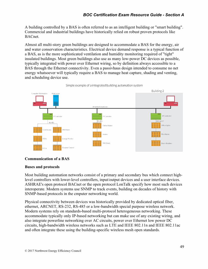
BOC Certification Exam Resource Guide - Section A
49 © 2017 Northwest Energy Efficiency Council
A building controlled by a BAS is often referred to as an intelligent building or "smart building". Commercial and industrial buildings have historically relied on robust proven protocols like BACnet.
Almost all multi-story green buildings are designed to accommodate a BAS for the energy, air and water conservation characteristics. Electrical device demand response is a typical function of a BAS, as is the more sophisticated ventilation and humidity monitoring required of "tight" insulated buildings. Most green buildings also use as many low-power DC devices as possible, typically integrated with power over Ethernet wiring, so by definition always accessible to a BAS through the Ethernet connectivity. Even a passivhaus design intended to consume no net energy whatsoever will typically require a BAS to manage heat capture, shading and venting, and scheduling device use.
Communication of a BAS
Buses and protocols
Most building automation networks consist of a primary and secondary bus which connect high-level controllers with lower-level controllers, input/output devices and a user interface devices. ASHRAE's open protocol BACnet or the open protocol LonTalk specify how most such devices interoperate. Modern systems use SNMP to track events, building on decades of history with SNMP-based protocols in the cmputer networking world.
Physical connectivity between devices was historically provided by dedicated optical fiber, ethernet, ARCNET, RS-232, RS-485 or a low-bandwidth special purpose wireless network. Modern systems rely on standards-based multi-protocol heterogeneous networking. These accommodate typically only IP-based networking but can make use of any existing wiring, and also integrate powerline networking over AC circuits, power over Ethernet low power DC circuits, high-bandwidth wireless networks such as LTE and IEEE 802.11n and IEEE 802.11ac and often integrate these using the building-specific wireless mesh open standards.
BOC Certification Exam Resource Guide - Section A
50 © 2017 Northwest Energy Efficiency Council
Current systems provide interoperability at the application level, allowing users to mix-and-match devices from different manufacturers, and to provide integration with other compatible building control systems. These typically rely on SNMP, long used for this same purpose to integrate diverse computer networking devices into one coherent network.
Types of inputs and outputs
Analog inputs are used to read a variable measurement. Examples are temperature, humidity and pressure sensors. A digital input indicates if a device is turned on or not. Analog outputs control the speed or position of a device, such as a variable frequency drive or a valve or damper actuator. Digital outputs are used to open and close relays and switches. An example would be to turn on the parking lot lights when a photocell indicates it is dark outside.
Air-Side Economizer Operation & Verification Pacific Northwest National Laboratory
http://buildingretuning.pnnl.gov/documents/pnnl_sa_86706.pdf
Review this guide to understand how to verify economizer functionality and to detect deficiencies in operation and control.
STUDY QUESTIONS: What data is needed to verify economizer control?
______________________________________________________________________
What trends do you look for to analyze economizer operation?
______________________________________________________________________
What is the formula for determining Outside Air Fraction (OAF)?
______________________________________________________________________
Summary
The purpose of the air-side economizer control guide is to show, through use of examples of good and bad operation, how air-side economizers should be utilized and efficiently controlled.
An air-side economizer is a duct/damper arrangement in an air-handling unit (AHU) along with automatic controls that allow an AHU to use outdoor-air to reduce or eliminate the need for mechanical cooling. When there is a need for cooling and if the outdoor-air conditions are favorable for economizing (outdoor-air temperature is less than return-air temperature), unconditioned outdoor-air can be used to meet all of the cooling energy needs or supplement mechanical cooling. In a properly configured economizer control sequence, the outdoor-, return- and exhaust-air dampers sequence together to mix and balance the air-flow streams to meet the AHU discharge-air temperature set point.

BOC Certification Exam Resource Guide - Section A
51 © 2017 Northwest Energy Efficiency Council
In humid climates, the use of dry-bulb temperature based economizers is not recommended. However, if used, the outdoor-air temperature should be 5 to 10oF lower than the return-air temperature. There are times when economizing should not be used. This includes during building warm-up periods and cool-down periods, when the outdoor conditions are not favorable for economizing, or during unoccupied periods, when the supply fan is operating (unless introduction of outdoor-air is advantageous to the unoccupied or cool-down period).
When an economizer is not controlled correctly, it may go unnoticed because mechanical cooling will compensate to maintain the discharge-air at the desired discharge-air set point. This may include periods of time where too much outdoor-air is being introduced to the AHU (when the economizer control is attempting to maintain a minimum outdoor-air set point) or when there is not enough outdoor-air being introduced to the AHU (when the economizer control is attempting to bring in the maximum amount of outdoor-air). Failure to correct/mitigate this situation, in all likelihood, will lead to increased fan, cooling and heating energy consumption.
Data need to verify the air-side economizer control
To analyze and detect deficiencies in economizer operation and control, for single-duct variable-air-volume (SDVAV) AHU(s), the following parameters must be monitored using the trending capabilities of the building automation system (BAS):
• Outdoor-air temperature (OAT) • Mixed-air temperature (MAT) • Discharge-air temperature and set point (DAT and DATSP) • Return-air temperature (RAT) • Outdoor-air damper position signal (OAD) • Cooling-coil-valve signal (CCV) • Outdoor-air fraction (OAF).
In most BAS’s, the outdoor-air fraction is probably not computed and trended. If OAF is not recorded in the BAS, it can be computed externally using the outdoor-, return- and mixed-air temperatures:
OAF = [(MAT – RAT)/(OAT – RAT)]
The recommended frequency of data collection is between 5- and 30-minutes. When analyzing the air-side economizer operation, the trends to look for include:
• How close is the outdoor-air fraction compared to the outdoor-air damper position signal? • Is the minimum outdoor-air damper position reasonable (between 10% and 20%)? • Is the outdoor-air damper open when outdoor conditions are not favorable (outdoor-air
temperature > return-air temperature)? • Is the outdoor-air damper closed or at minimum position when outdoor conditions are
favorable for economizing and the AHU is in cooling mode? • Does the cooling coil operate during economizer mode? • Does the cooling coil operate when the outdoor-air temperature is lower than the
discharge-air temperature set point?

BOC Certification Exam Resource Guide - Section A
52 © 2017 Northwest Energy Efficiency Council
• When the cooling coil is open, is the outdoor-air damper fully open, if the conditions are favorable for economizing?
• Do outdoor-air dampers close to minimum position for freeze protection? • Is the mixed-air temperature between the outdoor-air and return-air temperatures?
Air Flow Measurements https://www.krueger-hvac.com/files/white%20papers/white_paper_airflow_measurements.pdf
STUDY QUESTIONS: What four issues does proper air flow control address?
______________________________________________________________________
What are two examples of where air flow set points can waste energy?
______________________________________________________________________
If minimum air flows are set too high, what can happen?
______________________________________________________________________
OVERVIEW
The control of airflow rate in VAV systems is important for several reasons, including acoustics, ventilation, energy management and occupant comfort. Most VAV terminals today are supplied with pressure independent controllers of some type (pneumatic, analog electronic and digital electronic), and all require an inlet flow sensor supplied by the VAV box manufacturer. Indeed, upcoming revisions to ASHRAE Standard 62 will likely require pressure independent controls to assure minimum ventilation rates in spaces. In 2003, Krueger introduced an advanced design cross flow sensor (the K4 “LineaCross”) that provides the most powerful set of inlet sensor attributes available in the industry today. This paper discusses many aspects regarding inlet sensing of VAV terminals.
CONTROL ISSUES
The goals of a flow control design must be understood before deciding on the best solution to inlet flow sensing.
• Acoustics: In order to have the lowest sound generation, a VAV terminal box is usually selected as large as possible. A larger size usually (but not always) results in lower sound generation due to the lower velocities for a given flow rate, than a smaller one. At the same time, units are selected at the highest flow-rate as possible, to achieve the best flow signal at minimum flows. Additionally, the supply diffusers are selected as small as possible, to maximize air distribution performance (see white paper on diffuser selection). If a unit delivers more air than designed during maximum flow conditions, it is therefore probable that excessive noise will be noticed in the occupied space. Therefore, maximum flow limiting needs to be as accurate as possible. At the low end of the control
BOC Certification Exam Resource Guide - Section A
53 © 2017 Northwest Energy Efficiency Council
range, if the airflow set-point is below the working range of the velocity controller, the unit may cycle between closed and partially open, causing some varying sound levels leading to occupant complaints.
• Ventilation: Minimum ventilation rates demand that low-end flows be as accurate as possible to ensure that adequate ventilation is supplied during periods of low sensed load. This requires the flow at the low end of the scale be as accurate as possible. In addition to poor ventilation, space sub-cooling can create occupant comfort problems if minimum flows are set at too high a level.
• Energy Management: The temperature feedback loop with pressure independent controls probably takes care of any flow errors that might be experienced in the mid range of a VAV boxes flow range, which should be most of the time if the unit is sized properly. As a space becomes too warm or too cold, the damper will be adjusted to respond to the sensed temperature change. With Single Duct VAV boxes during reheat, however, the heating airflow set point is typically constant, and if more air is supplied than desired, energy is wasted as excessive chilled primary air is reheated. With Series Fan Terminals, excessive primary airflow at the maximum VAV damper flow setting can cause overpressure of the unit, sending chilled primary air into the plenum, with a number of negative consequences.
• Occupant Comfort: The purpose of the pressure independent VAV controller is to maintain occupant comfort at the lowest possible airflow rate. Poor airflow sensing can create uncomfortable temperature swings, again resulting in occupant complaints. This often results in excessive energy use from uncontrolled supplemental fans or space heaters employed by occupants to augment a poorly controlled system. Therefore, the maximum, minimum and minimum reheat flow points are probably critical for acoustical and energy control. Intermediate control is not as sensitive, but excessive swings in flow are to be avoided. The selection and design of an inlet sensor can have a significant impact on the resulting space conditions and building energy consumption.

BOC Certification Exam Resource Guide - Section A
54 © 2017 Northwest Energy Efficiency Council
Turning Vanes Turning Vane. (n.d.) McGraw-Hill Dictionary of Architecture and Construction. (2003). Retrieved April 14 2017 from http://encyclopedia2.thefreedictionary.com/turning+vane
STUDY QUESTION: What purpose does a turning vane serve?
______________________________________________________________________
One of a number of curved fins which are placed in air-conditioning ductwork at a point where the duct changes direction; used to promote a more uniform airflow and to reduce pressure drop.
Turning Vane
Area 3 - Document equipment maintenance
Preventive Maintenance Practices http://www.auditor.leg.state.mn.us/ped/pedrep/0006all.pdf; Best Practices & Actions for Successful Preventative Maintenance; Office of the Legislature Auditor State of Minnesota (OLA), Report #00-06, 4/12/2000
[See Figure 2.1 below]

BOC Certification Exam Resource Guide - Section A
55 © 2017 Northwest Energy Efficiency Council
BOC Certification Exam Resource Guide - Section A
56 © 2017 Northwest Energy Efficiency Council
Computerized maintenance management system O&M Best Practices Guide, Release 3.0
https://energy.gov/sites/prod/files/2013/10/f3/omguide_complete.pdf
STUDY QUESTIONS: What are some examples of how a CMMS could improve an existing maintenance program?
______________________________________________________________________
What is one of the greatest benefits of implementing a CMMS?
______________________________________________________________________
What is essential information to collect on an HVAC log sheet?
______________________________________________________________________
What are examples of useful equipment analysis reports?
______________________________________________________________________
What information is provided in an equipment failure analysis report?
______________________________________________________________________
What information does a CMMS’s preventive maintenance report provide?
______________________________________________________________________
What basic information should appear on a maintenance log sticker for Tracking of Air Handler Maintenance And Air Filter Change-Outs?
______________________________________________________________________
4.1 Introduction
A computerized maintenance management system (CMMS) is a type of management software that performs functions in support of management and tracking of O&M activities.
4.2 CMMS Needs Assessment
In determining the need for a CMMS, facility managers should assess their current mode of operation. Key questions to ask include:
• Do you have an effective way to generate and track work orders? How do you verify the work was done efficiently and correctly? What is the notification function upon completion?
• Are you able to access historical information on the last time a system was serviced, by whom, and for what condition?

BOC Certification Exam Resource Guide - Section A
57 © 2017 Northwest Energy Efficiency Council
• How are your spare-parts inventories managed and controlled? Do you have either excess inventories or are you consistently waiting for parts to arrive?
• Do you have an organized system to store documents (electronically) related to O&M procedures, equipment manuals, and warranty information?
• When service staff are in the field what assurances do you have that they are compliant with all life, health and safety issues (e.g., lock and tag) and are using the right tools/equipment for the task?
• How are your assets, i.e., equipment and systems, tracked for reporting and planning?
If the answers to these questions are not well defined or lacking – you may consider investigating the benefits a well implemented CMMS may offer.
HVAC PM Log
http://www.state.nj.us/health/workplacehealthandsafety/documents/peosh/hvacpmlog.pdf
Review log sheet. See PDF in Appendix.
Equipment of a CMMS
http://www.wbdg.org/om/cmms.php; uploaded to Whole Building Design Guide (WBDG), National Institute of Building Sciences, © 2015
The CMMS may include a module that allows an operator to keep accurate and detailed records of each piece of equipment. This module would include equipment-related data, such as bill of material, Preventive Maintenance (PM) schedule, service contracts, safety procedures, measurement points, multiple meters, inspection routes, specification data (name plate), equipment downtime, and related documentation. This equipment data is used for managing day-to-day operations and also as historical data that can be used to help make cost-effective "replace or repair" decisions. The data can also be used to develop additional management information, such as building equipment downtime failure code hierarchies for use in maintenance management metrics.
CMMS Types and Features
A. In a Computerized Maintenance Management System. https://en.wikipedia.org/wiki/Computerized_maintenance_management_system
Computerized maintenance management system (CMMS), also known as computerized maintenance management information system (CMMIS), is a software package that maintains a computer database of information about an organization's maintenance operations.[1] This information is intended to help maintenance workers do their jobs more effectively (for example, determining which machines require maintenance and which storerooms contain the spare parts they need) and to help management make informed decisions (for example, calculating the cost of machine breakdown repair versus preventive maintenance for each machine, possibly leading to better allocation of resources). CMMS data may also be used to verify regulatory compliance.
BOC Certification Exam Resource Guide - Section A
58 © 2017 Northwest Energy Efficiency Council
CMMS packages may be used by any organization that must perform maintenance on equipment, assets and property. Some CMMS products focus on particular industry sectors (e.g. the maintenance of vehicle fleets or health care facilities). Other products aim to be more general.
CMMS packages can produce status reports and documents giving details or summaries of maintenance activities. The more sophisticated the package, the more analysis facilities are available.
Many CMMS packages can be either web-based, meaning they are hosted by the company selling the product on an outside server, or LAN based, meaning that the company buying the software hosts the product on its own server.
B. In a preventive maintenance service report for the facility.
Preventive Maintenance Reports Use the following reports to analyze your PM workload, craftsperson performance, equipment maintenance, and so forth. By carefully analyzing these reports, you can assess how to better manage your labor resources and proactively maintain your facility. For all of these reports you must first enter a date range during which work is to completed or has been completed.
Forecasting Reports
• Overdue PM Work -- Review this report to check the scheduled PM jobs that have missed any scheduled maintenance since the last time work orders were created for them. This report displays all scheduled PM jobs for which the difference between the system date and the Date of Last PM is greater than the maintenance interval. For each schedule, this report uses the frequency interval set with the Current Frequency field of the PM Schedules table.
• PM Work Forecast -- Use this report to display PM schedules coming due during a time period that you specify. Narrow the list of work by setting additional filter options if you wish. Use the tabs to display the upcoming work according to date, trade, or trade by building. For each schedule, the report displays the currently set frequency interval, the forecast date, and other PM schedule data.
• PM Resources Requirement Forecast -- For the PM work due during the period you specify (and meeting other optional filters that you specify), this task offers the following reports to document resource requirements for executing the upcoming work. The reports use the currently set frequency level for each schedule.
o Labor -- Review this tab to see the estimated hours for each trade for each day in the specified period.
o Parts -- Review this tab to check estimated part requirements for each day in the specified period.
o Tools -- Review this tab to see estimated tool type requirements for each day in the specified period.
• Labor, Parts, and Tools -- Review this tab to check trade, part, and tool type requirements for each day in the specified date range. These forecasts can be used in
BOC Certification Exam Resource Guide - Section A
59 © 2017 Northwest Energy Efficiency Council
conjunction with other statistics, such as part lead times, to estimate when resources should be purchased.
• 52 Week PM Work Schedule -- This set of reports document the scheduled PM work coming due during for each week during the specified time period, up to 365 days from the starting date. From this report, you can also adjust schedules in order to balance workloads. See 52 Week PM Work Schedule report.
Equipment Analysis Reports
• Equipment Maintenance History -- This report displays the on demand and preventive maintenance performed on each piece of equipment during the time specified period. Examine this report to see the frequency of on demand work; equipment with a lot of on demand work may require more preventive maintenance work. To display pie charts of equipment maintenance costs by equipment, equipment standard, and problem type, click the "Show Chart" option. Click on a section of the pie chart to see the work requests contributing to this data.
• Equipment Failure Analysis -- For each piece of equipment for which work has been performed during the specified date range, this report calculates and displays the causes of breakdowns, Mean-Time-Between-Failures (MTBF) statistics, Mean-Time-To-Repair (MTTR) statistics, the number of failures, and downtime versus up-time statistics.
o Changes in MTBF over time can indicate the effectiveness of your maintenance efforts. MTBF is determined from the total number of days in the time period divided by (number of failures - 1). For example, suppose you have four failures in a 100 day period: on days 1, 33, 66, and 100. The MTBF is 33.33; that is, 100/(4-1).
o The formula includes decreasing the number of failures by 1 to ensure that the statistic measures the time between failures, and not the number of failures. MTTR is calculated as the average time between the date and time work is requested and it is completed.
o Downtime is determined by summing up the downtime values recorded on work requests completed in the specified time period. Up-time is calculated by multiplying the "# of Normal Operating Hours/day" value by the number of days in the specified time period.
• Equipment Replacement Analysis -- Use this report to check equipment that should be replaced due to age or excessive maintenance costs. The report lists equipment exceeding age of life expectancy or whose maintenance costs for the past 365 days exceed the original purchase price.
Labor Analysis Reports
• Trades Workload -- For each trade, this report displays the active work requests whose assigned dates are within the specified date range. Review this report to check the workload for each trade per day.
• Trades Availability -- This report lists the total available and committed hours for each trade on each day of the specified time period. Review this report to check how many hours are still available for each trade per day. The committed hours per trade are
BOC Certification Exam Resource Guide - Section A
60 © 2017 Northwest Energy Efficiency Council
determined from all the work requests that are not yet completed and have assigned trade requirements.
• Trades Performance -- This report displays each trade and the completed work requests to which the trade was assigned as a resource. For each trade, the report totals and averages the estimated and actual work time for work requests completed during the specified date range. Review this report to check how each trade is performing relative to estimate.
Note: With preventive maintenance systems, you estimate work time at the trade level, but you then record actual time worked at the craftsperson level. Therefore, to generate this report, the system sums the actual hours of the craftspersons of each trade to determine the actual hours worked per trade.
• Craftspersons Workload -- This report displays the active work requests assigned to each craftsperson. The work requests, sorted by their assigned date range, display the total estimated hours for each day. Run this report to see how much work each craftsperson has on each day during the specified date range.
• Craftspersons Availability -- For each date of the specified time period, this report lists each craftsperson's total available and committed hours . Review this report to check how many hours each craftsperson has available per day. The availability is based on the craftsperson's value for the Standard Hours Available field. Hours committed derive from work request assignments. When assigning craftspersons to work orders, supervisors can consult this report to see availability. You can also view this data in a chart form.
• Craftspersons Performance -- For each craftsperson, the report displays closed work requests assigned to this craftsperson with estimated and actual work time. Use this report to see each craftsperson's performance relative to estimated work time.
• Craftspersons Time Usage by Work Type -- For each craftsperson, this report shows all assigned closed work requests. The assigned work is sorted by work type so that you can see how much time was used for each type of work (travel time, setup time, and work time). Review this report to check how craftspersons have used their time. Note that craftspersons and supervisors can record Work Type information when they update work request with details about the job.
• Craftspersons Time Usage by Date and Time -- For each craftsperson, this report shows all assigned closed work requests, sorted by date and time the work was assigned to the craftsperson. Review this report to check how craftspersons have used their time.
Current PM Work
Overdue PM Work Requests -- This report lists PM Work Requests that are overdue, and charts the number overdue by the number of days. If you have developed SLAs to define service windows for response and completion times, the report additionally color-codes any work requests that have not met these time frames and are escalated.
You can filter the overdue work requests according to the assigned supervisor or work team by entering these parties in the filter.
BOC Certification Exam Resource Guide - Section A
61 © 2017 Northwest Energy Efficiency Council
For detailed information on the component work requests of a bar in the chart, double-click on the bar and the system presents a pop-up listing the work requests contributing to this data. The requests highlighted in orange are escalated for a response; those highlighted in red are escalated for completion
The number of days overdue is calculated by comparing the current date with the wr.date_assigned for all PM Work Requests (problem_type = “PREVENTIVE MAINT”) where wr.status IN (‘AA’, ‘I’) AND wr.date_assigned is less than current date
On a maintenance log sticker attached to equipment.
https://hdsupplysolutions.com/shop/p/maintenance-log-sticker-package-of-100-p259825
Electrical Systems
STUDY QUESTIONS: State energy codes in the United States require automatic shutoff of lighting in commercial buildings greater than 5,000 square feet in size, with few exceptions. What three field adjustments might be necessary for occupancy sensors to ensure effective operation?
______________________________________________________________________
What are the three components of the Ohm’s Law formula?
______________________________________________________________________
The color of the ceilings, walls, floors and furniture have a major impact on the effectiveness of a building’s daylighting strategy. In order of importance, the lightest colors should be installed where?
______________________________________________________________________
Ohm's Law http://www.rapidtables.com/electric/ohms-law.htm; Ohm’s Law Calculator (Short Form), 2014 RapidTables.com
Ohm's law shows a linear relationship between the voltage and the current in an electrical circuit. The resistor's voltage drop and resistance set the DC current flow through the resistor. With water flow analogy we can imagine the electric current as water current through pipe, the resistor as a thin pipe that limits the water flow, the voltage as height difference of the water that enables the water flow.
Check out Ohm’s Law Calculator http://www.rapidtables.com/calc/electric/ohms-law-calculator.htm

BOC Certification Exam Resource Guide - Section A
62 © 2017 Northwest Energy Efficiency Council
Energy Code Requirements for Occupancy Sensors http://ecmweb.com/lighting-amp-control/occupancy-sensors-101;
Occupancy Sensors 101 – Five Steps to an Effective Installation, by Craig DiLouie, 4/1/2007 EC&M (Electrical Construction & Maintenance).
State energy codes in the United States, which must be at least as stringent as the ASHRAE/IES 90.1-1999 standard, require automatic shutoff of lighting in commercial buildings greater than 5,000 square feet in size, with few exceptions. Scheduling devices, such as intelligent control panels or occupancy sensors, can accomplish this task.
According to the U.S. Environmental Protection Agency, energy savings from using such devices can range from 40% to 46% in classrooms, 13% to 50% in private offices, 30% to 90% in restrooms, 22% to 65% in conference rooms, 30% to 80% in corridors, and 45% to 80% in storage areas. Besides providing a means of minimizing energy consumption, additional uses of occupancy sensors include security (by indicating that an area is occupied), and minimizing light pollution (by reducing the usage of lighting operating at night), whether it be outdoor lighting or indoor lighting emitting through windows or skylights.
NOTE: The article covers five steps. Below is Step 5: Installation and commissioning. See article for Steps 1-4
Step 5: Installation and commissioning
To ensure occupant satisfaction with a sensor installation, the manufacturer and installer may collaborate on startup and field commissioning. This is because occupancy sensor settings should be calibrated to the specific application needs.
Commissioning begins during the design process, in ensuring that the right sensor technology was selected, and that it was placed correctly on the plans. For example, if an ultrasonic sensor is placed near a source of high airflow, it can experience false “ONs.” Similarly, if a PIR sensor is placed in such a way that it has a blind spot in part of the room, it will not detect occupancy in that part of the room and produce false “OFFs”.
The first step for the installer in performing field commissioning is to ensure that the wiring connecting the sensor or power pack to the power and loads is correct. Occupancy sensors must be installed according to manufacturer instructions and wiring diagrams. The next step is to verify proper placement and, if applicable, orientation of the sensors, so that they match the specifications and construction drawings.
Otherwise, there are two or three possible primary adjustments that may need to be tuned in the field. This should be coordinated with furniture placement, as occasionally furniture or equipment may be moved or relocated, which can affect sensor placement and/or orientation.
1. The time delay provides control of the time in which the sensor will turn off the load after the room is unoccupied. While a lower time delay offers more energy savings, it might cause occupant dissatisfaction if the lights prematurely turn off. A longer time delay

BOC Certification Exam Resource Guide - Section A
63 © 2017 Northwest Energy Efficiency Council
offers more assurances that the light will not turn off if there is little activity in the room. Generally, a 15-minute delay is recommended.
2. The sensitivity setting allows the installer a way of controlling the range and sensitivity to movement of the sensor.
3. The light level setting, available with models that offer a daylight-switching feature, allows the installer to hold off turning on the electric lights if the daylight level in the room is adequate.
The project may use self-calibrating and self-adaptive sensors, which automatically adjust their delay and sensitivity settings over time.
After commissioning is completed, users should be told about the intent and functionality of the controls. This is critical because if users do not understand the controls, they will complain and attempt to override or bypass them. Documentation and instructions should be given to the owner's maintenance personnel so that they can maintain and re-tune the system as needed.
Select light colors for interior finishes Guide for Daylighting Schools, developed by Innovative Design, 2004
http://www.lrc.rpi.edu/programs/daylighting/pdf/guidelines.pdf;
The color of the ceilings, walls, floors and furniture have a major impact on the effectiveness of a building’s daylighting strategy. When considering finish surfaces, install light colors (white is best) to ensure daylight is reflected throughout the space. In order of importance, the lightest colors should be installed at the sky wells, ceiling, walls, furniture and floor.
All have an impact. The darker these surfaces are, the more glazing will be required to access daylight to achieve the same net effect.
How to Read a Motor Nameplate http://www.vfds.com/blog/how-to-read-a-motor-nameplate
Review the terminology and definitions at this URL.
Review BOC 211 – Motors in Facilities section on motor nameplate terminology.
STUDY QUESTION: When re-ordering a motor, what information on the motor nameplate is needed?
______________________________________________________________________
Ever order a motor on power, speed, and enclosure? PO says maybe "5 hp, 1,800 rpm, TEFC."
New-motor nameplate says "HP 5, RPM 1748, Enclosure TEFC, Des B, Frame 184T, Amps 7.0,
PH 3, HZ 60, Duty Cont, Volts 460, Type P, Amb 40 C, SF 1.15, INS CL F, EFF 82.5, P.F. 80, DE bearing 35BC02JGG30A26, ODE bearing 3OBC02JGG3OA26."

BOC Certification Exam Resource Guide - Section A
64 © 2017 Northwest Energy Efficiency Council
Should you reject the motor because it is not rated at 1,800 rpm? What does all that extra information on the nameplate mean? Do you care? The answers are "maybe," "we'll discuss it in a minute," and "you probably should."
HVAC Systems http://www.epa.gov/Ozone/title6/608/608fact.html; Complying with the Section 608 Refrigerant Recycling Rule, posting last updated 1/26/2013
STUDY QUESTIONS: What ozone-depleting substances are found in refrigeration equipment?
______________________________________________________________________
What are the regulatory requirements for preventing the release of these substances into the atmosphere when maintaining, servicing, repairing or disposing of refrigeration equipment?
______________________________________________________________________
What is the minimum information required in a refrigerant charge record?
______________________________________________________________________
The best two seasons for HVAC maintenance are ______________________?
General Maintenance Checklist for HVAC Contractors https://www.energystar.gov/index.cfm?c=heat_cool.pr_maintenance
Maintenance Checklist
Maintain your equipment to prevent future problems and unwanted costs. Keep your cooling and heating system at peak performance by having a contractor do annual pre-season check-ups. Contractors get busy once summer and winter come, so it's best to check the cooling system in the spring and the heating system in the fall. To remember, you might plan the check-ups around the time changes in the spring and fall.
A typical maintenance check-up should include the following.
• Check thermostat settings to ensure the cooling and heating system keeps you comfortable when you are home and saves energy while you are away.
• Tighten all electrical connections and measure voltage and current on motors. Faulty electrical connections can cause unsafe operation of your system and reduce the life of major components.
• Lubricate all moving parts. Parts that lack lubrication cause friction in motors and increases the amount of electricity you use.

BOC Certification Exam Resource Guide - Section A
65 © 2017 Northwest Energy Efficiency Council
• Check and inspect the condensate drain in your central air conditioner, furnace and/or heat pump (when in cooling mode). A plugged drain can cause water damage in the house and affect indoor humidity levels.
• Check controls of the system to ensure proper and safe operation. Check the starting cycle of the equipment to assure the system starts, operates, and shuts off properly.
Cooling Specific
• Clean evaporator and condenser air conditioning coils. Dirty coils reduce the system's ability to cool your home and cause the system to run longer, increasing energy costs and reducing the life of the equipment.
• Check your central air conditioner's refrigerant level and adjust if necessary. Too much or too little refrigerant will make your system less efficient increasing energy costs and reducing the life of the equipment.
• Clean and adjust blower components to provide proper system airflow for greater comfort levels. Airflow problems can reduce your system's efficiency by up to 15 percent.
Heating Specific
• Check all gas (or oil) connections, gas pressure, burner combustion and heat exchanger. Improperly operating gas (or oil) connections are a fire hazard and can contribute to health problems. A dirty burner or cracked heat exchanger causes improper burner operation. Either can cause the equipment to operate less safely and efficiently.
Refrigerant charging records https://www.epa.gov/sites/production/files/documents/RealZeroGuidetoGoodLeakTesting.pdf
The amount of refrigerant charge is important:
• Undercharged systems are less efficient, have higher running costs and might not be able to meet the load.
• Overcharged systems have greater potential leakage. In extreme cases, over charging will increase head pressure and reduce performance and efficiency.
Charging to a known weight is the most accurate method of achieving the correct charge - use this when possible, especially on systems without a receiver. If you are charging to a full liquid line sight glass ensure there is a load on the system, otherwise you may not charge enough refrigerant to meet a high load. Be aware that bubbling in the sight glass can also indicate that the liquid line filter drier is blocked or the condenser is significantly undersized or blocked.
Charging to a pressure or frost line are not accurate methods of achieving the correct charge amount.
Records
BOC Certification Exam Resource Guide - Section A
66 © 2017 Northwest Energy Efficiency Council
US based regulation for the US Clean Air Act Section 608 record keeping requirement referenced here: https://www.epa.gov/section608/major-recordkeeping-requirements-stationary-refrigeration
Major Recordkeeping Requirements for Stationary Refrigeration EPA regulations (40 CFR Part 82, Subpart F) under Section 608 of the Clean Air Act include recordkeeping requirements that are specific to different persons or companies involved with stationary refrigeration and air-conditioning equipment. This page provides a brief overview of these requirements.
Technicians
Technicians must keep a copy of their proof of certification at their place of business.
Technicians servicing appliances that contain 50 or more pounds of ozone depleting refrigerant must provide the owner with an invoice that indicates the amount of refrigerant added to the appliance. Starting January 1, 2019, this requirement will also apply to HFC and other non-exempt substitute refrigerants. At that date technicians will also be required to provide records of leak inspections and tests performed to verify repairs of leaking appliances.
Starting January 1, 2018, technicians disposing of appliances containing between 5 and 50 pounds of refrigerant must keep records of the disposal. These are typically field-installed appliances such as residential AC split systems. This requirement applies to appliances containing ozone depleting or HFC refrigerant. The records primarily include: location and date of recovery, type of refrigerant recovered, monthly totals of the amounts recovered, and amounts sent for reclamation.
Additional information about servicing stationary refrigeration and air-conditioning equipment.
Owners or Operators
Owners or operators of appliances that contain 50 or more pounds of ozone depleting refrigerant must keep servicing records documenting the date and type of service, as well as the quantity of refrigerant added. Starting January 1, 2019, this requirement will also apply to HFC and other non-exempt substitute refrigerants. At that date owners or operators will also be required to maintain records of leak inspections and tests performed to verify repairs of leaking appliances.
Also starting January 1, 2019, owners or operators must submit a report to EPA for any appliance containing 50 or more pounds of refrigerant that leaks 125 percent or more of the full charge in a calendar year. This report must describe efforts to identify leaks and repair the appliance.
Additional information for owners or operators of:
• Commercial stationary refrigeration and air-conditioning equipment. • Residential stationary refrigeration and air-conditioning equipment.

BOC Certification Exam Resource Guide - Section A
67 © 2017 Northwest Energy Efficiency Council
Retro-Commissioning http://www.oregon.gov/energy/energy-oregon/Documents/SB1149Retrocommissioning%20Handbook%20for%20Facility%20Managers.pdf
Objectives of the Retro-commissioning Process, Retro-commissioning Handbook for Facility Managers, prepared for the Oregon Office of Energy by Portland Energy Conservation, Inc. (PECI), 3/2001
STUDY QUESTIONS: What are the objectives of the retrocommissioning process?
______________________________________________________________________
Repair work is a component of retro-commissioning – True or False?
______________________________________________________________________
Objectives of the Retro-commissioning Process
Commissioning of existing buildings or “retro-commissioning,” is a systematic process applied to existing buildings for identifying and implementing operational and maintenance improvements and for ensuring their continued performance over time. Retro-commissioning assures system functionality. It is an inclusive and systematic process that intends not only to optimize how equipment and systems operate, but also to optimize how the systems function together. Although retro-commissioning may include recommendations for capital improvements, the primary focus is on using O&M tune-up activities and diagnostic testing to optimize the building systems. Retro-commissioning is not a substitute for major repair work. Repairing major problems is a must before retro-commissioning can be fully completed.
The following have been identified by owners as the primary objectives for retro-commissioning a project:
• Bring equipment to its proper operational state • Reduce complaints • Reduce energy and demand costs • Increase equipment life • Improve indoor air quality • Increase tenant satisfaction • Improve facility operation and maintenance • Reduce staff time spent on emergency calls
Definition
Existing-building commissioning, also known as retrocommissioning, is an event in the life of a building that applies a systematic investigation process for improving or optimizing a building’s operation and maintenance. It may or may not emphasize bringing the building back to its

BOC Certification Exam Resource Guide - Section A
68 © 2017 Northwest Energy Efficiency Council
original intended design. In fact, the original design documentation may no longer exist or be relevant. The goals and objectives for applying the process, as well as the level of rigor, may vary depending on the current needs of the owner, budget, and condition of the equipment. The retrocommissioning process most often focuses on dynamic energy-using systems with the goal of reducing energy waste, obtaining energy cost savings, and identifying and fixing existing problems.
4. Practice Questions and Answers The practice questions below are retired exam questions from early versions of the certification exam. Candidates should review the questions and answers, and be prepared to answer questions of similar content.
1. When evaluating water-glycol systems, which of the following is the most critical concern?
a) That the glycol-water solution is constantly circulated even when the facility is not in use. b) That the desired proportion of glycol to water is maintained. c) That the color of the glycol matches a test standard provided by the chemical manufacturer. d) That the temperature of the glycol-water loop is always above 32°F
2. Which of the following is the least likely detail to be included in a schedule for balancing valves in an O&M manual?
a) The normal position of the valve b) The desired water flow through the valve c) The type of valve d) The size of the valve
3. What is the primary function of a capacitor in an electrical circuit?
a) To store electrical flow b) To resist the flow of electricity c) To store electrical charge d) To open or close a circuit
4. The intention of a refrigerant metering device in refrigeration systems is to …
a) Convert the gas refrigerant into a liquid b) Raise the temperature of the refrigerant c) Maintain a pressure differential, a high (and low) pressure in the system d) Lubricate the refrigeration loop

BOC Certification Exam Resource Guide - Section A
69 © 2017 Northwest Energy Efficiency Council
5. In pneumatics, what is the typical main air pressure to the controller?
a) 5 PSI b) 20 PSI c) 50 PSI d) 100 PSI
6. If a 12 Volt DC electrical circuit is drawing 2.5 amperes, what is the resistance of the circuit?
a) 2 ohms b) 2.4 ohms c) 3.0ohms d) 4.8 ohms
7. Evaporators in refrigeration systems perform which of the following functions?
a) Regulate the amount of outside air entering a facility. b) Drip water across a coil to accelerate the cooling process. c) Regulate the pressure across a refrigerant system. d) It is where heat absorbed from a media converts a liquid refrigerant into a gas.
8. Which document is the most likely place to find an itemized list of all equipment to be maintained in a facility including the known maintenance requirements for each component?
a) The as-built drawings b) The latest test and balance report c) The O&M manual d) The service log for the facility
9. Refrigeration tubing is measured by
a) the inside diameter (ID) b) rounding to the nearest 1/8” c) the outside diameter (OD) d) the wall thickness
10. Putting a system under vacuum
a) raises the boiling point b) lowers the boiling point c) has no effect on the boiling point d) prevents air and contaminants from entering the system
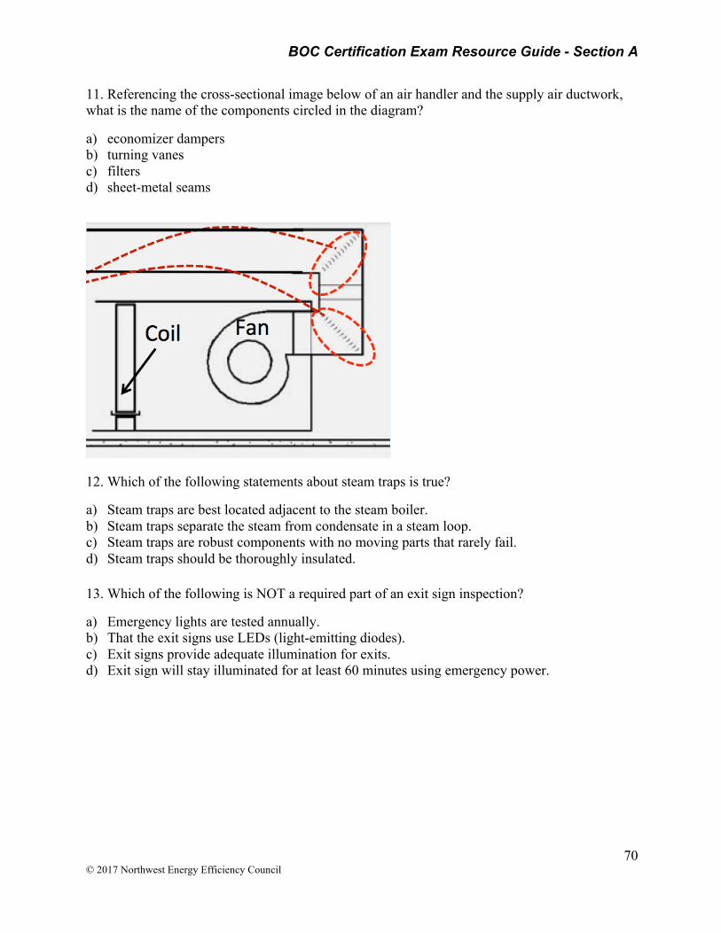
BOC Certification Exam Resource Guide - Section A
70 © 2017 Northwest Energy Efficiency Council
11. Referencing the cross-sectional image below of an air handler and the supply air ductwork, what is the name of the components circled in the diagram?
a) economizer dampers b) turning vanes c) filters d) sheet-metal seams
12. Which of the following statements about steam traps is true?
a) Steam traps are best located adjacent to the steam boiler. b) Steam traps separate the steam from condensate in a steam loop. c) Steam traps are robust components with no moving parts that rarely fail. d) Steam traps should be thoroughly insulated.
13. Which of the following is NOT a required part of an exit sign inspection?
a) Emergency lights are tested annually. b) That the exit signs use LEDs (light-emitting diodes). c) Exit signs provide adequate illumination for exits. d) Exit sign will stay illuminated for at least 60 minutes using emergency power.
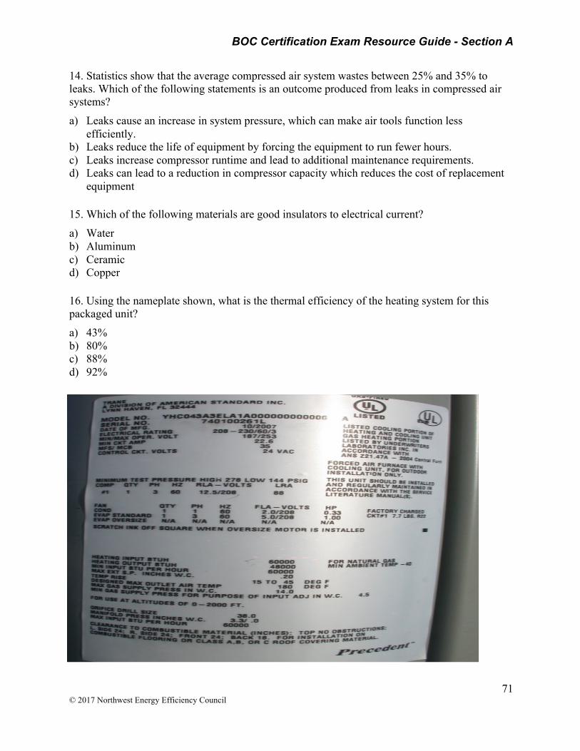
BOC Certification Exam Resource Guide - Section A
71 © 2017 Northwest Energy Efficiency Council
14. Statistics show that the average compressed air system wastes between 25% and 35% to leaks. Which of the following statements is an outcome produced from leaks in compressed air systems?
a) Leaks cause an increase in system pressure, which can make air tools function less efficiently.
b) Leaks reduce the life of equipment by forcing the equipment to run fewer hours. c) Leaks increase compressor runtime and lead to additional maintenance requirements. d) Leaks can lead to a reduction in compressor capacity which reduces the cost of replacement
equipment
15. Which of the following materials are good insulators to electrical current?
a) Water b) Aluminum c) Ceramic d) Copper
16. Using the nameplate shown, what is the thermal efficiency of the heating system for this packaged unit?
a) 43% b) 80% c) 88% d) 92%

BOC Certification Exam Resource Guide - Section A
72 © 2017 Northwest Energy Efficiency Council
Practice Question Answers:
1. B 2. B 3. C 4. C 5. B 6.D 7. D 8. C 9. C 10. B 11. B 12. B 13. B
14. C 15. C 16. B
###