Embed Size (px)
Citation preview

SECTION 8-3. WELDING
8-3.__ WELDINGGENERALUnless otherwise specified, Section 8-3, "Welding," shall apply to any welding that is
specified to conform to an AWS welding code.Requirements of the AWS welding codes shall apply unless otherwise specified in the
Standard Specifications, on the plans, or in these special provisions. Wherever the abbreviation AWS is used, it shall be equivalent to the abbreviations ANSI/AWS or AASHTO/AWS.
Wherever reference is made to the following AWS welding codes in the Standard Specifications, on the plans, or in these special provisions, the year of adoption for these codes shall be as listed:
AWS Code Year of AdoptionD1.1 2008D1.3 2008D1.4 2005D1.5 2008D1.6 2007D1.8 2009
Flux cored welding electrodes conforming to the requirements of AWS A5.20 E6XT-4 or E7XT-4 shall not be used to perform welding for this project.
Unless otherwise specified, Clause 6.1.3 of AWS D1.1, paragraph 1 of Section 7.1.2 of AWS D1.4, and Clause 6.1.1.2 of AWS D1.5, are replaced with the following:
The QC Inspector shall be the duly designated person who acts for and on behalf of the Contractor for inspection, testing, and quality related matters for all welding.
Quality Assurance (QA) is the prerogative of the Engineer. The QA Inspector is the duly designated person who acts for and on behalf of the Engineer.
The QC Inspector shall be responsible for quality control acceptance or rejection of materials and workmanship.
When the term "Inspector" is used without further qualification, it shall refer to the QC Inspector.
Inspection and approval of all joint preparations, assembly practices, joint fit-ups, welding techniques, and the performance of each welder, welding operator, and tack welder shall be documented by the QC Inspector on a daily basis for each day welding is performed. For each inspection, including fit-up, Welding Procedure Specification (WPS) verification, and final weld inspection, the QC Inspector shall confirm and document compliance with the requirements of the AWS or other specified code criteria and the requirements of these special provisions on all welded joints before welding, during welding, and after the completion of each weld.
The Engineer shall have the authority to verify the qualifications or certifications of any welder, QC Inspector, or NDT personnel to specified levels by retests or other means approved by the Engineer.
When joint weld details that are not prequalified to the details of Clause 3 of AWS D1.1 or to the details of Figure 2.4 or 2.5 of AWS D1.5 are proposed for use in the work, the joint details, their intended locations, and the proposed welding parameters and essential variables, shall be approved by the Engineer. The Contractor shall allow the Engineer 15 days to complete the review of the proposed joint detail locations.
In addition to the requirements of AWS D1.1, welding procedure qualifications for work welded in conformance with this code shall conform to the following:
When a nonstandard weld joint is to be made using a combination of WPSs, a single test may be conducted combining the WPSs to be used in production, provided the essential variables, including weld bead placement, of each process are limited to those established in Table 4.5.
Upon approval of the proposed joint detail locations and qualification of the proposed joint details, welders and welding operators using these details shall perform a qualification test plate using the WPS variables and the joint detail to be used in production. The test plate shall have the maximum thickness to be used in production and a minimum length of 18 inches. The test plate shall be mechanically and radiographically tested. Mechanical and radiographic testing and acceptance criteria shall be as specified in the applicable AWS codes.
The Engineer will witness all qualification tests for WPSs that were not previously approved by the Department.
In addition to the requirements specified in the applicable code, the period of effectiveness for a welder's or welding operator's qualification shall be a maximum of 3 years for the same weld process, welding position, and weld type. If welding will be performed without gas shielding, then qualification shall also be without gas shielding. Excluding welding of fracture critical members, a valid qualification at the beginning of work on a contract will be acceptable for the entire period of the contract, as long as the welder's or welding operator's work remains satisfactory.
The Contractor shall notify the Engineer 7 days prior to performing any procedure qualification tests. Witnessing of qualification tests by the Engineer shall not constitute approval of the intended joint locations, welding parameters, or essential variables. The Contractor shall notify the Engineer using the "Standard TL-38 Inspection Form" located at:
http://www.dot.ca.gov/hq/esc/Translab/OSM/smbforms.htm
Clause 6.14.6, "Personnel Qualification," of AWS D1.1, Section 7.8, "Personnel Qualification," of AWS D1.4, and Clause 6.1.3.4, "Personnel Qualification," of AWS D1.5 are replaced with the following:
Personnel performing nondestructive testing (NDT) shall be qualified and certified in conformance with the requirements of the American Society for Nondestructive Testing (ASNT) Recommended Practice No. SNT-TC-1A and the Written Practice of the NDT firm. The Written Practice of the NDT firm shall meet or exceed the guidelines of the ASNT Recommended Practice No. SNT-TC-1A. Individuals who perform NDT, review the results, and prepare the written reports shall be either:
A. Certified NDT Level II technicians, or;B. Level III technicians who hold a current ASNT Level III certificate in that discipline
and are authorized and certified to perform the work of Level II technicians.
Clause 6.6.5, "Nonspecified NDT Other than Visual," of AWS D1.1, Section 7.6.5 of AWS D1.4 and Clause 6.6.5 of AWS D1.5 shall not apply.
For any welding, the Engineer may direct the Contractor to perform NDT that is in addition to the visual inspection or NDT specified in the AWS or other specified welding codes, in the
Standard Specifications, or in these special provisions. Except as provided for in these special provisions, additional NDT required by the Engineer, and associated repair work, will be paid for as extra work as provided in Section 4-1.03D, "Extra Work," of the Standard Specifications. Prior to release of welded material by the Engineer, if testing by NDT methods other than those originally specified discloses an attempt to defraud or reveals a gross nonconformance, all costs associated with the repair of the deficient area, including NDT of the weld and of the repair, and any delays caused by the repair, shall be at the Contractor’s expense. A gross nonconformance is defined as the sum of planar type rejectable indications in more than 20 percent of the tested length.
When less than 100 percent of NDT is specified for any weld, it is expected that the entire length of weld meet the specified acceptance-rejection criteria. Should any welding deficiencies be discovered by additional NDT directed or performed by the Engineer that utilizes the same NDT method as that originally specified, all costs associated with the repair of the deficient area, including NDT of the weld and of the weld repair, and any delays caused by the repair, shall be at the Contractor's expense.
Repair work to correct welding deficiencies discovered by visual inspection directed or performed by the Engineer, and any associated delays or expenses caused to the Contractor by performing these repairs, shall be at the Contractor's expense.
WELDING QUALITY CONTROLWelding quality control shall conform to the requirements in the AWS or other specified
welding codes, the Standard Specifications, and these special provisions.Unless otherwise specified, welding quality control shall apply to work welded in
conformance with the provisions in the following:
A. Section 49, "Piling," Section 52, "Reinforcement," Section 55, "Steel Structures," and Section 75-1.035, "Bridge Joint Restrainer Units," of the Standard Specifications
B. "Structural Steel for Building Work" of these special provisions
Unless otherwise specified, Clauses 6.1.4.1 and 6.1.4.3 of AWS D1.1, paragragh 2 of Section 7.1.2 of AWS D1.4, and Clauses 6.1.3.2 through 6.1.3.3 of AWS D1.5 are replaced with the following:
The QC Inspector shall be currently certified as an AWS Certified Welding Inspector (CWI) in conformance with the requirements in AWS QC1, "Standard for AWS Certification of Welding Inspectors."
The QC Inspector may be assisted by an Assistant QC Inspector provided that this individual is currently certified as an AWS Certified Associate Welding Inspector (CAWI) in conformance with the requirements in AWS QC1, "Standard for AWS Certification of Welding Inspectors." The Assistant QC Inspector may perform inspection under the direct supervision of the QC Inspector provided the assistant is always within visible and audible range of the QC Inspector. The QC Inspector shall be responsible for signing all reports and for determining if welded materials conform to workmanship and acceptance criteria. The ratio of QC Assistants to QC Inspectors shall not exceed 5 to 1.
The Contractor shall designate in writing a welding Quality Control Manager (QCM). The QCM shall be responsible directly to the Contractor for the quality of welding, including materials and workmanship, performed by the Contractor and subcontractors.

The QCM shall be the sole individual responsible to the Contractor for submitting, receiving, reviewing, and approving all correspondence, required submittals, and reports to and from the Engineer. The QCM shall be a registered professional engineer or shall be currently certified as a CWI.
Unless the QCM is hired by a subcontractor providing only QC services, the QCM shall not be employed or compensated by any subcontractor, or by other persons or entities hired by subcontractors, who will provide other services or materials for the project. The QCM may be an employee of the Contractor.
The QCM shall sign and furnish to the Engineer, a Certificate of Compliance in conformance with the provisions in Section 6-1.07, "Certificates of Compliance," of the Standard Specifications for each item of work for which welding was performed. The certificate shall state that all of the materials and workmanship incorporated in the work, and all required tests and inspections of this work, have been performed in conformance with the details shown on the plans, the Standard Specifications, and these special provisions.
Welding inspection personnel or NDT firms to be used in the work shall not be employed or compensated by any subcontractor, or by other persons or entities hired by subcontractors, who will provide other services or materials for the project, except for the following conditions:
A. The work is welded in conformance with AWS D1.5 and is performed at a permanent fabrication or manufacturing facility that is certified under the AISC Quality Certification Program, Category CBR, Major Steel Bridges and Fracture Critical endorsement F, when applicable.
B. Structural steel for building work is welded in conformance with AWS D1.1 and is performed at a permanent fabrication or manufacturing facility that is certified under the AISC Quality Certification Program, Category STD, Standard for Steel Building Structures.
For welding performed at such facilities, the inspection personnel or NDT firms may be employed or compensated by the facility performing the welding provided the facility maintains a QC program that is independent from production.
Unless otherwise specified, an approved independent third party will witness the qualification tests for welders or welding operators. The independent third party shall be a current CWI and shall not be an employee of the contractor performing the welding. The Contractor shall allow the Engineer 15 days to review the qualifications and copy of the current certification of the independent third party.
Prior to submitting the Welding Quality Control Plan (WQCP) required herein, a prewelding meeting between the Engineer, the Contractor's QCM, and a representative from each entity performing welding or inspection for this project, shall be held to discuss the requirements for the WQCP.
Information regarding the contents, format, and organization of a WQCP, is available at the Transportation Laboratory and at:
http://www.dot.ca.gov/hq/esc/Translab/OSM/smbresources.htm
The Contractor shall submit to the Engineer, in conformance with the provisions in Section 5-1.02, "Plans and Working Drawings," of the Standard Specifications, 2 copies of a separate WQCP for each subcontractor or supplier for each item of work for which welding is to be performed.
The Contractor shall allow the Engineer 15 days to review the WQCP submittal after a complete plan has been received. No welding shall be performed until the WQCP is approved in writing by the Engineer.
An amended WQCP or any addendum to the approved WQCP shall be submitted to, and approved in writing by the Engineer, for proposed revisions to the approved WQCP. An amended WQCP or addendum will be required for revisions to the WQCP, including but not limited to a revised WPS; additional welders; changes in NDT firms, QC, or NDT personnel or procedures; or updated systems for tracking and identifying welds. The Engineer shall have 7 days to complete the review of the amended WQCP or addendum. Work affected by the proposed revisions shall not be performed until the amended WQCP or addendum has been approved.
After final approval of the WQCP, amended WQCP, or addendum, the Contractor shall submit 7 copies to the Engineer of the approved documents. A copy of the Engineer approved document shall be available at each location where welding is to be performed.
All welding will require inspection by the Engineer. The Contractor shall request inspection at least 3 business days prior to the beginning of welding for locations within California and 5 business days for locations outside of California. The Contractor shall request inspection at:
http://www.dot.ca.gov/hq/esc/Translab/OSM/smbforms.htm
Continuous inspection shall be provided when any welding is being performed. Continuous inspection, as a minimum, shall include having a QC Inspector within such close proximity of all welders or welding operators so that inspections by the QC Inspector of each welding operation at each welding location does not lapse for a period exceeding 30 minutes.
A daily production log for welding shall be kept for each day that welding is performed. The log shall clearly indicate the locations of all welding. The log shall include the welders' names, amount of welding performed, any problems or deficiencies discovered, and any testing or repair work performed, at each location. The daily report from each QC Inspector shall also be included in the log.
The following items shall be included in a Welding Report that is to be submitted to the Engineer within 15 days following the performance of any welding:
A. A daily production log.B. Reports of all visual weld inspections and NDT.C. Radiographs and radiographic reports, and other required NDT reports.D. A summary of welding and NDT activities that occurred during the reporting period.E. Reports of each application of heat straightening.F. A summarized log listing the rejected lengths of weld by welder, position, process, joint
configuration, and piece number.G. Documentation that the Contractor has evaluated all radiographs and other nondestructive
tests and corrected all rejectable deficiencies, and that all repaired welds have been reexamined using the required NDT and found acceptable.
The following information shall be clearly written on the outside of radiographic envelopes: name of the QCM, name of the nondestructive testing firm, name of the radiographer, date, contract number, complete part description, and all included weld numbers, report numbers, and station markers or views, as detailed in the WQCP. In addition, all interleaves shall have clearly written on them the part description and all included weld numbers and station markers or views, as detailed in the WQCP. A maximum of 2 pieces of film shall be used for each interleave.

Reports of all visual inspections and NDT shall be signed by the inspector or technician and submitted daily to the QCM for review and signature prior to submittal to the Engineer. Corresponding names shall be clearly printed or typewritten next to all signatures. Reports of all NDT, whether specified, additional, or informational, performed by the Contractor shall be submitted to the Engineer.
The Engineer will review the Welding Report to determine if the Contractor is in conformance with the WQCP. Except for field welded steel pipe piling, the Engineer shall be allowed 15 days to review the report and respond in writing after the complete Welding Report has been received. Prior to receiving notification from the Engineer of the Contractor's conformance with the WQCP, the Contractor may encase in concrete or cover welds for which the Welding Report has been submitted. However, should the Contractor elect to encase or cover those welds prior to receiving notification from the Engineer, it is expressly understood that the Contractor shall not be relieved of the responsibility for incorporating material in the work that conforms to the requirements of the plans and specifications. Material not conforming to these requirements will be subject to rejection.
For field welded steel pipe piling, including bar reinforcement in the piling, the Contractor shall allow the Engineer 2 business days to review the Welding Report and respond in writing after the required items have been received. No field welded steel pipe piling shall be installed, and no reinforcement in the piling shall be encased in concrete until the Engineer has approved the above requirements in writing.
In addition to the requirements in AWS D1.1 and AWS D1.5, third-time excavations of welds or base metal to repair unacceptable discontinuities, regardless of NDT method, and all repairs of cracks require prior approval of the Engineer.
The Engineer shall be notified immediately in writing when welding problems, deficiencies, base metal repairs, or any other type of repairs not submitted in the WQCP are discovered, and also of the proposed repair procedures to correct them. For requests to perform third-time excavations or repairs of cracks, the Contractor shall include an engineering evaluation of the proposed repair. The engineering evaluation, at a minimum, shall address the following:
A. What is causing each defect?B. Why the repair will not degrade the material properties?C. What steps are being taken to prevent similar defects from happening again?
The Contractor shall allow the Engineer 7 days to review these procedures. No remedial work shall begin until the repair procedures are approved in writing by the Engineer.
Clause 6.5.4 of AWS D1.5 is replaced with the following:
The QC Inspector shall inspect and approve each joint preparation, assembly practice, welding technique, joint fit-up, and the performance of each welder, welding operator, and tack welder to make certain that the applicable requirements of this code and the approved Welding Procedure Specification (WPS) are met. The QC Inspector shall examine the work to make certain that it meets the requirements of Clauses 3 and 6.26. The size and contour of all welds shall be measured using suitable gages. Visual inspection for cracks in welds and base metal, and for other discontinuities shall be aided by strong light, magnifiers, or such other devices as may be helpful. Acceptance criteria different from those specified in this code may be used when approved by the Engineer.

In addition to the requirements of AWS D1.5, Clause 5.12 or 5.13, welding procedures qualification for work welded in conformance with that code shall conform to the following requirements:
A. Unless considered prequalified, fillet welds shall be qualified in each position. The fillet weld soundness test shall be conducted using the essential variables of the WPS as established by the Procedure Qualification Record (PQR).
B. For qualification of joints that do not conform to Figures 2.4 and 2.5 of AWS D1.5, a minimum of 2 WPS qualification tests are required. The tests shall be conducted using both Figure 5.1 and Figure 5.3. The test conforming to Figure 5.1 shall be conducted in conformance with AWS D1.5, Clause 5.12 or 5.13. The test conforming to Figure 5.3 shall be conducted using the welding electrical parameters that were established for the test conducted conforming to Figure 5.1. The ranges of welding electrical parameters established during welding per Figure 5.1 in conformance with AWS D1.5, Clause 5.12, shall be further restricted according to the limits in Table 5.3 during welding per Figure 5.3.
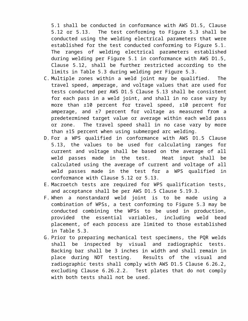
C. Multiple zones within a weld joint may be qualified. The travel speed, amperage, and voltage values that are used for tests conducted per AWS D1.5 Clause 5.13 shall be consistent for each pass in a weld joint, and shall in no case vary by more than ±10 percent for travel speed, ±10 percent for amperage, and ±7 percent for voltage as measured from a predetermined target value or average within each weld pass or zone. The travel speed shall in no case vary by more than ±15 percent when using submerged arc welding.
D. For a WPS qualified in conformance with AWS D1.5 Clause 5.13, the values to be used for calculating ranges for current and voltage shall be based on the average of all weld passes made in the test. Heat input shall be calculated using the average of current and voltage of all weld passes made in the test for a WPS qualified in conformance with Clause 5.12 or 5.13.
E. Macroetch tests are required for WPS qualification tests, and acceptance shall be per AWS D1.5 Clause 5.19.3.
F. When a nonstandard weld joint is to be made using a combination of WPSs, a test conforming to Figure 5.3 may be conducted combining the WPSs to be used in production, provided the essential variables, including weld bead placement, of each process are limited to those established in Table 5.3.
G. Prior to preparing mechanical test specimens, the PQR welds shall be inspected by visual and radiographic tests. Backing bar shall be 3 inches in width and shall remain in place during NDT testing. Results of the visual and radiographic tests shall comply with AWS D1.5 Clause 6.26.2, excluding Clause 6.26.2.2. Test plates that do not comply with both tests shall not be used.
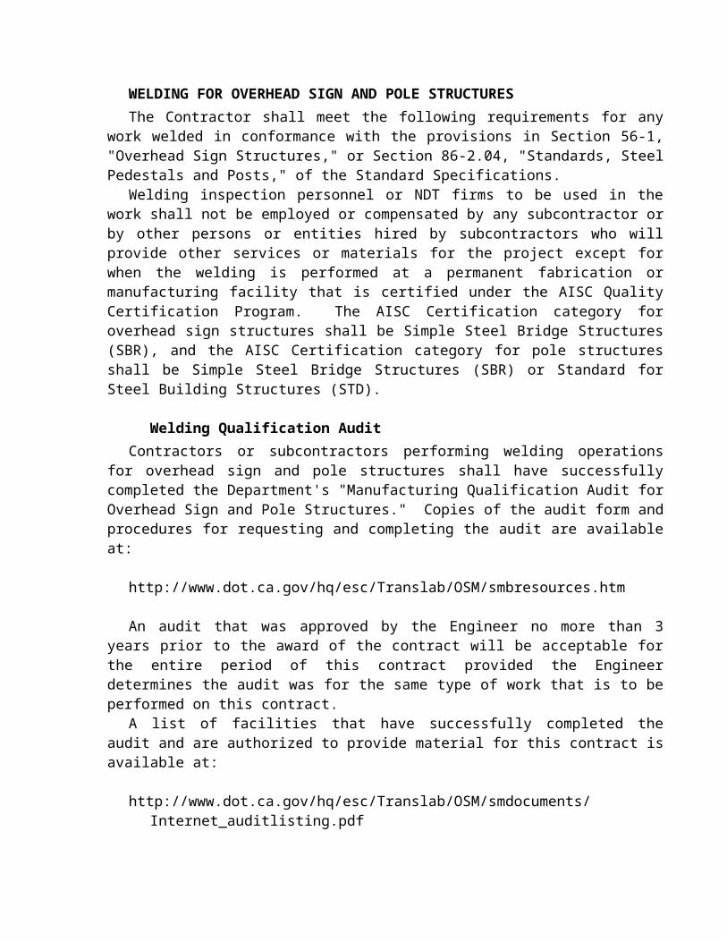
WELDING FOR OVERHEAD SIGN AND POLE STRUCTURESThe Contractor shall meet the following requirements for any work welded in conformance
with the provisions in Section 56-1, "Overhead Sign Structures," or Section 86-2.04, "Standards, Steel Pedestals and Posts," of the Standard Specifications.
Welding inspection personnel or NDT firms to be used in the work shall not be employed or compensated by any subcontractor or by other persons or entities hired by subcontractors who will provide other services or materials for the project except for when the welding is performed at a permanent fabrication or manufacturing facility that is certified under the AISC Quality Certification Program. The AISC Certification category for overhead sign structures shall be Simple Steel Bridge Structures (SBR), and the AISC Certification category for pole structures shall be Simple Steel Bridge Structures (SBR) or Standard for Steel Building Structures (STD).
Welding Qualification AuditContractors or subcontractors performing welding operations for overhead sign and pole
structures shall have successfully completed the Department's "Manufacturing Qualification Audit for Overhead Sign and Pole Structures." Copies of the audit form and procedures for requesting and completing the audit are available at:
http://www.dot.ca.gov/hq/esc/Translab/OSM/smbresources.htm
An audit that was approved by the Engineer no more than 3 years prior to the award of the contract will be acceptable for the entire period of this contract provided the Engineer determines the audit was for the same type of work that is to be performed on this contract.
A list of facilities that have successfully completed the audit and are authorized to provide material for this contract is available at:
http://www.dot.ca.gov/hq/esc/Translab/OSM/smdocuments/Internet_auditlisting.pdf
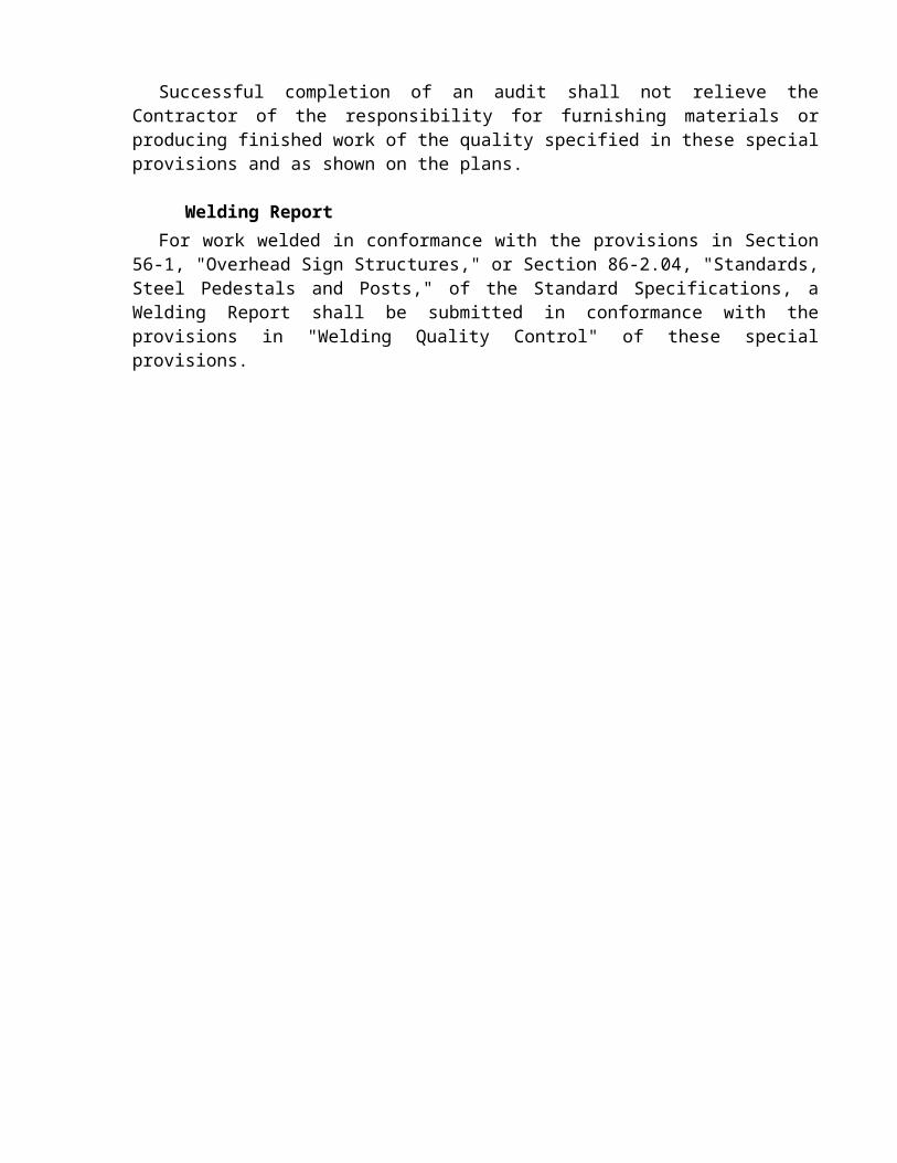
Successful completion of an audit shall not relieve the Contractor of the responsibility for furnishing materials or producing finished work of the quality specified in these special provisions and as shown on the plans.
Welding ReportFor work welded in conformance with the provisions in Section 56-1, "Overhead Sign
Structures," or Section 86-2.04, "Standards, Steel Pedestals and Posts," of the Standard Specifications, a Welding Report shall be submitted in conformance with the provisions in "Welding Quality Control" of these special provisions.

PAYMENTFull compensation for conforming to the requirements of "Welding" shall be considered as
included in the contract prices paid for the various items of work involved and no additional compensation will be allowed therefor.

10-1.__ PILINGGENERALPiling shall conform to the provisions in Section 49, "Piling," of the Standard Specifications,
and these special provisions.Unless otherwise specified, welding of any work performed in conformance with the
provisions in Section 49, "Piling," of the Standard Specifications, shall be in conformance with the requirements in AWS D1.1.
Attention is directed to "Project Information," "Precast Concrete Quality Control," and "Welding" of these special provisions.
Difficult pile installation is anticipated due to the presence of soft bay mud overlying dense soils, caving soils, hazardous and contaminated materials, serpentine materials, tidal flow fluctuation, high ground water, cobbles and boulders, subsurface concrete debris, low overhead clearance, underground utilities, overhead utilities, the requirements of pile embedment into rock, sound control, vibration monitoring and traffic control.
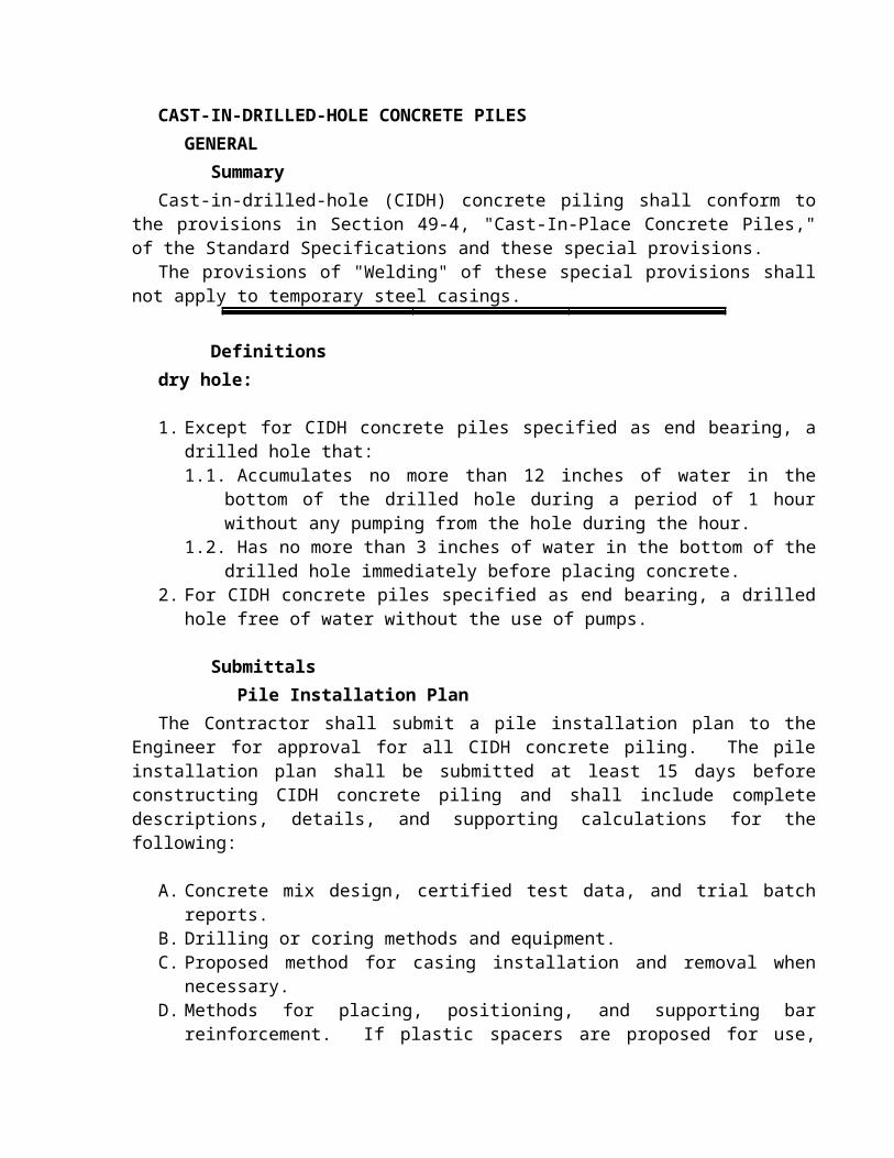
CAST-IN-DRILLED-HOLE CONCRETE PILESGENERAL
SummaryCast-in-drilled-hole (CIDH) concrete piling shall conform to the provisions in Section 49-4,
"Cast-In-Place Concrete Piles," of the Standard Specifications and these special provisions.The provisions of "Welding" of these special provisions shall not apply to temporary steel
casings.
Definitionsdry hole:
1. Except for CIDH concrete piles specified as end bearing, a drilled hole that:1.1. Accumulates no more than 12 inches of water in the bottom of the drilled hole
during a period of 1 hour without any pumping from the hole during the hour.1.2. Has no more than 3 inches of water in the bottom of the drilled hole immediately
before placing concrete.2. For CIDH concrete piles specified as end bearing, a drilled hole free of water without the
use of pumps.
SubmittalsPile Installation Plan
The Contractor shall submit a pile installation plan to the Engineer for approval for all CIDH concrete piling. The pile installation plan shall be submitted at least 15 days before constructing CIDH concrete piling and shall include complete descriptions, details, and supporting calculations for the following:
A. Concrete mix design, certified test data, and trial batch reports.B. Drilling or coring methods and equipment.C. Proposed method for casing installation and removal when necessary.D. Methods for placing, positioning, and supporting bar reinforcement. If plastic spacers are
proposed for use, include the manufacturer's data and a sample of the plastic spacer.E. Methods and equipment for determining the depth of concrete and actual and theoretical
volume placed, including effects on volume of concrete when any casings are withdrawn.F. Methods and equipment for verifying that the bottom of the drilled hole is clean before
placing concrete.G. Methods and equipment for preventing upward movement of reinforcement, including
the Contractor's means of detecting and measuring upward movement during concrete placement operations.
For concrete placed under slurry, the pile installation plan shall also include complete descriptions, details, and supporting calculations for the following:
A. Concrete batching, delivery, and placing systems, including time schedules and capacities. Time schedules shall include the time required for each concrete placing operation at each pile.
B. Concrete placing rate calculations. When requested by the Engineer, calculations shall be based on the initial pump pressures or static head on the concrete and losses throughout the placing system, including anticipated head of slurry and concrete to be displaced.
C. Suppliers’ test reports on the physical and chemical properties of the slurry and any proposed slurry chemical additives, including Material Safety Data Sheet.
D. Slurry testing equipment and procedures.E. Methods of removal and disposal of excavation, slurry, and contaminated concrete,
including removal rates.F. Methods and equipment for slurry agitating, recirculating, and cleaning.
QUALITY ASSURANCEConcrete Test Batch
Before concrete is deposited under slurry, a concrete test batch shall be produced and delivered to the project under conditions and in time periods similar to those expected during placement of concrete in the piles. Concrete shall be placed in an excavated hole or suitable container of adequate size to allow for testing as specified herein. Depositing of concrete under slurry will not be required. In addition to meeting the specified nominal slump, the concrete test batch shall meet the following requirements:
A. For piles where the time required for each concrete placing operation, as submitted in the placing plan, will be 2 hours or less, the concrete test batch shall demonstrate that the proposed concrete mix design achieves a slump of at least 7 inches after twice that time has elapsed.
B. For piles where the time required for each concrete placing operation, as submitted in the placing plan, will be more than 2 hours, the concrete test batch shall demonstrate that the proposed concrete mix design achieves a slump of at least 7 inches after that time plus 2 hours has elapsed.
The time period shall begin at the start of placement. Concrete shall not be vibrated or agitated during the test period. Slump tests will be performed in conformance with the requirements in California Test 556.
Upon completion of testing, concrete shall be disposed of in conformance with the provisions in Section 7-1.13, "Disposal of Material Outside the Highway Right of Way," of the Standard Specifications.
Preconstruction MeetingA preconstruction meeting for CIDH concrete pile construction shall be held (1) at least 5
business days after submitting the pile installation plan and (2) at least 10 days before the start of CIDH concrete pile construction.
The meeting shall include the Engineer, the Contractor, and any subcontractors involved in the CIDH concrete pile construction.
The purpose of this meeting is to:
A. Establish contacts and communication protocol between the Contractor, any subcontractors involved in CIDH concrete pile construction, and the Engineer
B. Review the construction process, acceptance testing, and anomaly mitigation of CIDH concrete piles
The Contractor shall schedule the meeting and provide a facility for the meeting. The Engineer will conduct the meeting. The following will be discussed:
A. Pile placement plan, dry and wetB. Acceptance testing, including gamma-gamma logging, cross-hole sonic logging, and
coringC. Pile Design Data FormD. Mitigation processE. Timeline and critical path activitiesF. Structural, geotechnical, and corrosion design requirementsG. Future meetings, if necessary, for pile mitigation and pile mitigation plan reviewH. Safety requirements, including Cal/OSHA and Tunnel Safety Orders
MATERIALSConcrete
Concrete deposited under slurry shall have a nominal slump equal to or greater than 7 inches, contain not less than 675 pounds of cementitious material per cubic yard, and be proportioned to prevent excessive bleed water and segregation. The nominal and maximum slump and penetration requirements in Section 90-6.06, "Amount of Water and Penetration," of the Standard Specifications shall not apply.
Concrete shall conform to the requirements in "Corrosion Control for Portland Cement Concrete" of these special provisions.
Concrete for portions of CIDH concrete piling to be formed shall contain not less than 675 pounds of cementitious material per cubic yard and shall contain 6.0±1.5 percent air entrainment in the freshly mixed concrete.
Aggregate GradingThe combined aggregate grading shall be either the 1-inch maximum grading, the 1/2-inch
maximum grading, or the 3/8-inch maximum grading and shall conform to the requirements in Section 90-3, "Aggregate Gradings," of the Standard Specifications.
When concrete is placed under slurry, the combined aggregate grading shall be either the 1/2-inch maximum grading or the 3/8-inch maximum grading and shall conform to the requirements in Section 90-3, "Aggregate Gradings," of the Standard Specifications.
SpacersSpacers shall conform to Section 52-1.07, "Placing," of the Standard Specifications, except
plastic spacers may be used.Plastic spacers shall conform to Sections 3.4 and 3.5 of the Concrete Reinforcing Steel
Institute's "Manual of Standard Practice" and shall have at least 25 percent of their gross plane area perforated to compensate for the difference in the coefficient of thermal expansion between the plastic and concrete. Plastic spacers shall be commercial quality.
Slurry
Mineral SlurryMineral slurry shall be mixed and thoroughly hydrated in slurry tanks, and slurry shall be
sampled from the slurry tanks and tested before placement in the drilled hole.

Slurry shall be recirculated or continuously agitated in the drilled hole to maintain the specified properties.
Recirculation shall include removal of drill cuttings from the slurry before discharging the slurry back into the drilled hole. When recirculation is used, the slurry shall be sampled and tested at least every 2 hours after beginning its use until tests show that the samples taken from the slurry tank and from near the bottom of the hole have consistent specified properties. Subsequently, slurry shall be sampled at least twice per shift as long as the specified properties remain consistent.
Slurry that is not recirculated in the drilled hole shall be sampled and tested at least every 2 hours after beginning its use. The slurry shall be sampled mid-height and near the bottom of the hole. Slurry shall be recirculated when tests show that the samples taken from mid-height and near the bottom of the hole do not have consistent specified properties.
Slurry shall also be sampled and tested before final cleaning of the bottom of the hole and again just before placing concrete. Samples shall be taken from mid-height and near the bottom of the hole. Cleaning of the bottom of the hole and placement of the concrete shall not start until tests show that the samples taken from mid-height and near the bottom of the hole have consistent specified properties.
Mineral slurry shall be tested for conformance to the requirements shown in the following table:
MINERAL SLURRYPROPERTY REQUIREMENT TESTDensity (pcf )
- before placement in the drilled hole- during drilling
- before final cleaning
- immediately before placing
concrete
64.3* to 69.1*
64.3* to 75.0*
Mud Weight (Density)
API 13B-1Section 1
Viscosity (seconds/quart)
bentonite
attapulgite
28 to 50
28 to 40
Marsh Funnel and Cup
API 13B-1Section 2.2
pH 8 to 10.5 Glass Electrode pH Meter or pH Paper
Sand Content(percent)
- before final cleaning
- immediately before placing
concrete
less than or equal to 4.0
SandAPI 13B-1Section 5
*When approved by the Engineer, slurry may be used in salt water, and the allowable densities may be increased up to 2 pcf.
Slurry temperature shall be at least 40°F when tested.

Any caked slurry on the sides or bottom of hole shall be removed before placing reinforcement. If concrete is not placed immediately after placing reinforcement, the reinforcement shall be removed and cleaned of slurry, the sides of the drilled hole cleaned of caked slurry, and the reinforcement again placed in the hole for concrete placement.
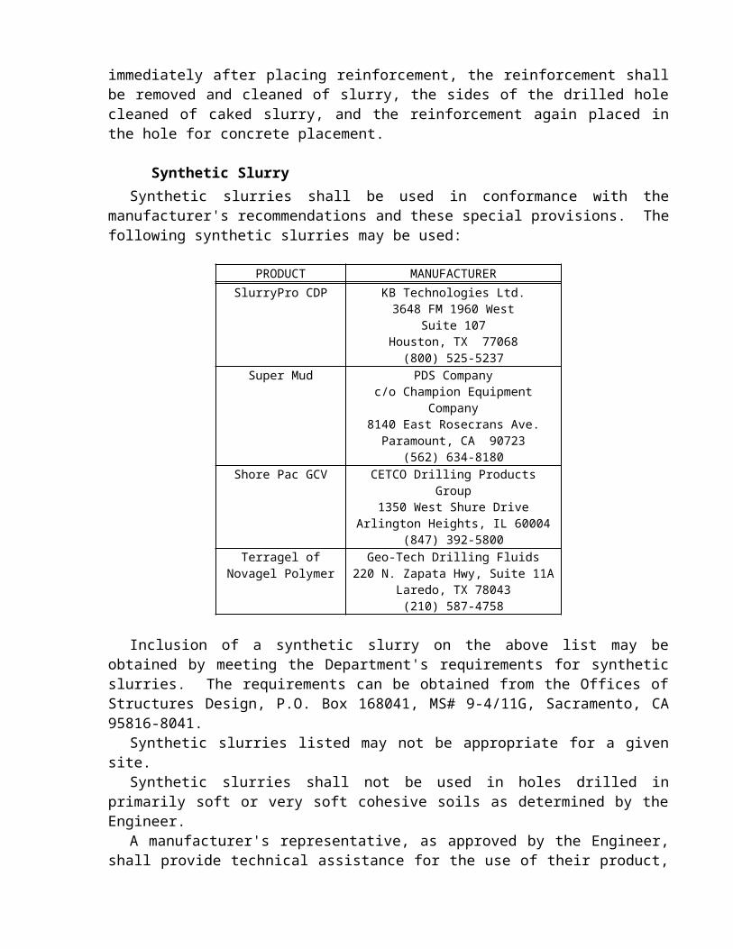
Synthetic SlurrySynthetic slurries shall be used in conformance with the manufacturer's recommendations
and these special provisions. The following synthetic slurries may be used:
PRODUCT MANUFACTURERSlurryPro CDP KB Technologies Ltd.
3648 FM 1960 WestSuite 107
Houston, TX 77068(800) 525-5237
Super Mud PDS Companyc/o Champion Equipment Company
8140 East Rosecrans Ave.Paramount, CA 90723
(562) 634-8180Shore Pac GCV CETCO Drilling Products Group
1350 West Shure DriveArlington Heights, IL 60004
(847) 392-5800Terragel of Novagel
PolymerGeo-Tech Drilling Fluids
220 N. Zapata Hwy, Suite 11ALaredo, TX 78043
(210) 587-4758
Inclusion of a synthetic slurry on the above list may be obtained by meeting the Department's requirements for synthetic slurries. The requirements can be obtained from the Offices of Structures Design, P.O. Box 168041, MS# 9-4/11G, Sacramento, CA 95816-8041.
Synthetic slurries listed may not be appropriate for a given site.Synthetic slurries shall not be used in holes drilled in primarily soft or very soft cohesive
soils as determined by the Engineer.A manufacturer's representative, as approved by the Engineer, shall provide technical
assistance for the use of their product, shall be at the site before introduction of the synthetic slurry into a drilled hole, and shall remain at the site until released by the Engineer.
Synthetic slurries shall be sampled and tested at both mid-height and near the bottom of the drilled hole. Samples shall be taken and tested during drilling as necessary to verify the control of the properties of the slurry. Samples shall be taken and tested when drilling is complete, but before final cleaning of the bottom of the hole. When samples are in conformance with the requirements shown in the following tables for each slurry product, the bottom of the hole shall be cleaned and any loose or settled material removed. Samples shall be obtained and tested after final cleaning and immediately before placing concrete.
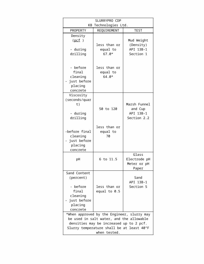
SlurryPro CDP synthetic slurries shall be tested for conformance to the requirements shown in the following table:
SLURRYPRO CDPKB Technologies Ltd.
PROPERTY REQUIREMENT TESTDensity (pcf )
- during drilling
- before final cleaning
- just before placing concrete
less than or equal to 67.0*
less than or equal to 64.0*
Mud Weight (Density)
API 13B-1Section 1
Viscosity (seconds/quart)
- during drilling
-before final cleaning
- just before placing concrete
50 to 120
less than or equal to 70
Marsh Funnel and Cup
API 13B-1Section 2.2
pH 6 to 11.5Glass Electrode pH Meter or pH Paper
Sand Content (percent)
- before final cleaning
- just before placing concrete
less than or equal to 0.5
SandAPI 13B-1Section 5
*When approved by the Engineer, slurry may be used in salt water, and the allowable densities may be increased up to 2 pcf.
Slurry temperature shall be at least 40°F when tested.
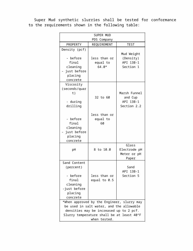
Super Mud synthetic slurries shall be tested for conformance to the requirements shown in the following table:
SUPER MUD PDS Company
PROPERTY REQUIREMENT TESTDensity (pcf)
- before final cleaning
- just before placing concrete
less than or equal to 64.0*
Mud Weight (Density)
API 13B-1Section 1
Viscosity (seconds/quart)
- during drilling
- before final cleaning
- just before placing concrete
32 to 60
less than or equal to 60
Marsh Funnel and Cup
API 13B-1Section 2.2
pH 8 to 10.0Glass Electrode pH Meter or pH Paper
Sand Content (percent)
- before final cleaning
-just before placing concrete
less than or equal to 0.5
SandAPI 13B-1Section 5
*When approved by the Engineer, slurry may be used in salt water, and the allowable densities may be increased up to 2 pcf.
Slurry temperature shall be at least 40°F when tested.
Shore Pac GCV synthetic slurries shall be tested for conformance to the requirements shown in the following table:
Shore Pac GCV CETCO Drilling Products Group
PROPERTY REQUIREMENT TESTDensity (pcf)
- before final cleaning
- just before placing concrete
less than or equal to 64.0*
Mud Weight (Density)
API 13B-1Section 1
Viscosity (seconds/quart)
- during drilling
- before final cleaning
- just before placing concrete
33 to 74
less than or equal to 57
Marsh Funnel and Cup
API 13B-1Section 2.2
pH 8.0 to 11.0Glass Electrode pH Meter or pH Paper
Sand Content (percent)
- before final cleaning
-just before placing concrete
less than or equal to 0.5
SandAPI 13B-1Section 5
*When approved by the Engineer, slurry may be used in salt water, and the allowable densities may be increased up to 2 pcf.
Slurry temperature shall be at least 40°F when tested.

Terragel or Novagel Polymer synthetic slurries shall be tested for conformance to the requirements shown in the following table:
TERRAGEL OR NOVAGEL POLYMER Geo-Tech Drilling Fluids
PROPERTY REQUIREMENT TESTDensity (pcf)
- during drilling
- before final cleaning
- just before placing concrete
less than or equal to 67.0*
less than or equal to 64.0*
Mud Weight (Density)
API 13B-1Section 1
Viscosity (seconds/quart)
- during drilling
- before final cleaning
- just before placing concrete
45 to 104
less than or equal to 104
Marsh Funnel and Cup
API 13B-1Section 2.2
pH 6.0 to 11.5Glass Electrode pH Meter or pH Paper
Sand Content (percent)
- before final cleaning
-just before placing concrete
less than or equal to 0.5
SandAPI 13B-1Section 5
*When approved by the Engineer, slurry may be used in salt water, and the allowable densities may be increased up to 2 pcf.
Slurry temperature shall be at least 40°F when tested.
Water SlurryAt the option of the Contractor, water may be used as slurry when casing is used for the
entire length of the drilled hole.Water slurry shall be tested for conformance to the requirements shown in the following
table:
WATER SLURRYPROPERTY REQUIREMENT TESTDensity (pcf)
- before final cleaning
- just before placing concrete
63.5*
Mud Weight (Density)
API 13B-1Section 1
Sand Content(percent)
- before final cleaning
-just before placing concrete
less than or equal to 0.5
SandAPI 13B-1Section 5
*When approved by the Engineer, salt water slurry may be used and the allowable densities may be increased up to 2 pcf.
CONSTRUCTIONGeneral
CIDH concrete piling 24 inches in diameter or larger may be constructed by excavation and depositing concrete under slurry.
Disposal of drill cuttings shall conform to the provisions in of these special provisions.Portions of CIDH concrete piling shown on the plans to be formed shall be formed and
finished in conformance with the provisions for concrete structures in Section 51, "Concrete Structures," of the Standard Specifications.
Unless otherwise shown on the plans, the bar reinforcing steel cage shall have at least 3 inches of clear cover measured from the outside of the cage to the sides of the hole or casing.
Spacers shall be placed at least 5 inches clear from any inspection tubes. Plastic spacers shall be placed around the circumference of the cage and at intervals along the length of the cage, as recommended by the manufacturer of the plastic spacer.
Placing ConcreteConcrete deposited under slurry shall be carefully placed in a compact, monolithic mass and
by a method that will prevent washing of the concrete. Concrete deposited under slurry need not be vibrated. Placing concrete shall be a continuous operation lasting not more than the time required for each concrete placing operation at each pile, as submitted in the placing plan, unless otherwise approved in writing by the Engineer. Concrete shall be placed with concrete pumps and delivery tube system of adequate number and size to complete the placing of concrete in the time specified. The delivery tube system shall consist of one of the following:
A. A tremie tube or tubes, each of which are at least 10 inches in diameter, fed by one or more concrete pumps.

B. One or more concrete pump tubes, each fed by a single concrete pump.
The delivery tube system shall consist of watertight tubes with sufficient rigidity to keep the ends always in the mass of concrete placed. If only one delivery tube is utilized to place the concrete, the tube shall be placed near the center of the drilled hole. Multiple tubes shall be uniformly spaced in the hole. Internal bracing for the steel reinforcing cage shall accommodate the delivery tube system. Tremies shall not be used for piles without space for a 10-inch tube.
Spillage of concrete into the slurry during concrete placing operations shall not be allowed. Delivery tubes shall be capped with a watertight cap, or plugged above the slurry level with a good quality, tight fitting, moving plug that will expel the slurry from the tube as the tube is charged with concrete. The cap or plug shall be designed to be released as the tube is charged. The pump discharge or tremie tube shall extend to the bottom of the hole before charging the tube with concrete. After charging the delivery tube system with concrete, the flow of concrete through a tube shall be induced by slightly raising the discharge end. During concrete placement, the tip of the delivery tube shall be maintained as follows to prevent reentry of the slurry into the tube. Until at least 10 feet of concrete has been placed, the tip of the delivery tube shall be within 6 inches of the bottom of the drilled hole, and then the embedment of the tip shall be maintained at least 10 feet below the top surface of the concrete. Rapid raising or lowering of the delivery tube shall not be permitted. If the seal is lost or the delivery tube becomes plugged and must be removed, the tube shall be withdrawn, the tube cleaned, the tip of the tube capped to prevent entrance of the slurry, and the operation restarted by pushing the capped tube 10 feet into the concrete and then reinitiating the flow of concrete.
When slurry is used, a fully operational standby concrete pump, adequate to complete the work in the time specified, shall be provided at the site during concrete placement. The slurry level shall be maintained 10 feet above the piezometric head or within 12 inches of the top of the drilled hole, whichever is higher.
A log of concrete placement for each drilled hole shall be maintained by the Contractor when concrete is deposited under slurry. The log shall show the pile location, tip elevation, dates of excavation and concrete placement, total quantity of concrete deposited, length and tip elevation of any casing, and details of any hole stabilization method and materials used. The log shall include a 8-1/2" x 11" sized graph of the concrete placed versus depth of hole filled. The graph shall be plotted continuously throughout placing of concrete. The depth of drilled hole filled shall be plotted vertically with the pile tip oriented at the bottom and the quantity of concrete shall be plotted horizontally. Readings shall be made at least at each 5 feet of pile depth, and the time of the reading shall be indicated. The graph shall be labeled with the pile location, tip elevation, cutoff elevation, and the dates of excavation and concrete placement. The log shall be delivered to the Engineer within 1 working day of completion of placing concrete in the pile.
After placing reinforcement and before placing concrete in the drilled hole, if drill cuttings settle out of the slurry, the bottom of the drilled hole shall be cleaned. The Contractor shall verify that the bottom of the drilled hole is clean.
If a temporary casing is used, maintain concrete placed under slurry at a level at least 5 feet above the bottom of the casing. The equivalent hydrostatic pressure inside the casing must be greater than the hydrostatic pressure on the outside of the casing. The withdrawal of the casing must not cause contamination of the concrete with slurry.
Material resulting from using slurry shall be disposed of in conformance with the provisions in Section 7-1.13, "Disposal of Material Outside the Highway Right of Way," of the Standard Specifications.
Disposal of material resulting from using slurry shall conform to the provisions in of these special provisions.

Acceptance Testing and MitigationVertical inspection pipes for acceptance testing shall be provided in all CIDH concrete piling
24 inches in diameter or larger, except when the holes are dry or when the holes are dewatered without the use of temporary casing in a manner that controls ground water.
The furnishing and placing of inspection pipes shall conform to the following:
A. Inspection pipes shall be Schedule 40 PVC pipe conforming to ASTM D 1785 with a nominal pipe size of 2 inches. Watertight PVC couplers conforming to ASTM D 2466 are permitted to facilitate pipe lengths in excess of those which are commercially available. The Contractor shall log the location of the inspection pipe couplers with respect to the plane of pile cut off, and these logs shall be delivered to the Engineer upon completion of the placement of concrete in the drilled hole.
B. Each inspection pipe shall be capped at the bottom and shall extend from 3 feet above the pile cutoff down to the bottom of the reinforcing cage. A temporary top cap or similar means shall be provided to keep the pipes clean before testing. If pile cutoff is below the ground surface or working platform, inspection pipes shall be extended to 3 feet above the ground surface or working platform. Approved covers or railings shall be provided and inspection pipes shall be located as necessary to minimize exposure of testing personnel to potential falling hazards.
C. Inspection pipes shall be completely clean, dry, and unobstructed at the time of testing providing a 2-inch diameter clear opening.
D. The inspection pipes shall be installed in straight alignment, parallel to the main reinforcement, and securely fastened in place to prevent misalignment during installation of the reinforcement and placing of concrete in the hole. The CIDH concrete piling shall be constructed so that the relative distance of inspection pipes to vertical steel reinforcement shall remain constant.
E. When any changes are made to the tip of CIDH concrete piling, the Contractor shall also extend the inspection pipes to the bottom of the reinforcing cage.
The following additional requirements apply if inspection pipes are not shown on the plans:
A. Inspection pipes shall be placed radially around the pile, inside the outermost spiral or hoop reinforcement and no more than 1 inch clear of the outermost spiral or hoop reinforcement.
B. Inspection pipes shall be placed around the pile at a uniform spacing not exceeding 33 inches measured along the circle passing through the centers of inspection pipes. A minimum of 2 inspection pipes per pile shall be used. Inspection pipes shall be placed to provide the maximum diameter circle that passes through the centers of the inspection pipes while maintaining the spacing required herein.
C. Inspection pipes shall be placed a minimum of 3 inches clear of the vertical reinforcement. When the vertical reinforcement configuration does not permit this clearance while achieving radial location requirements, distance to vertical rebar shall be maximized while still maintaining the requirement for radial location.
D. Where the dimensions of the pile reinforcement do not permit inspection pipes to be placed per these requirements, a plan for tube placement shall be submitted to the Engineer for approval in the Pile Placement Plan with a request for deviation before fabricating pile reinforcement.

After placing concrete, inspection pipes shall be filled with water to prevent debonding of the pipe. Before requesting acceptance tests, each inspection pipe shall be tested by the Contractor in the presence of the Engineer by passing a 1-1/4-inch-diameter rigid cylinder 4.5 feet long through the length of pipe. If an inspection pipe fails to pass the 1-1/4-inch-diameter cylinder, the Contractor shall immediately fill all inspection pipes in the pile with water.
For each inspection pipe that does not pass the 1-1/4-inch-diameter cylinder, the Contractor shall core a nominal 2-inch diameter hole through the concrete for the entire length of the pile. Cored holes shall be located as close as possible to the inspection pipes they are replacing and shall be no more than 5 inches clear from the reinforcement.
Coring shall not damage the pile reinforcement. Cored holes shall be made with a double wall core barrel system utilizing a split tube type inner barrel. Coring with a solid type inner barrel will not be allowed. Coring methods and equipment shall provide intact cores for the entire length of the pile. The coring operation shall be logged by an Engineering Geologist or Civil Engineer licensed in the State of California and experienced in core logging. Coring logs shall be in conformance with the Department's "Soil and Rock Logging, Classification, and Presentation Manual." Coring logs shall include Core Recovery (REC), Rock Quality Designation (RQD), locations of breaks, and complete descriptions of inclusions and voids encountered during coring, and shall be delivered to the Engineer upon completion. Concrete cores shall be preserved, identified with the exact location the core was recovered from within the pile, and delivered to the Engineer upon completion. The Engineer will evaluate the portion of the pile represented by the cored hole based on the submitted core logs.
Acceptance tests of the concrete will be made by the Engineer, without cost to the Contractor. Acceptance tests will evaluate the homogeneity of the placed concrete. Tests will include gamma-gamma logging conducted in conformance with California Test 233. The Contractor shall not conduct operations within 25 feet of the gamma-gamma logging operations. The Contractor shall separate reinforcing steel as necessary to allow the Engineer access to the inspection pipes to perform gamma-gamma logging or other acceptance testing. After requesting acceptance tests and providing access to the piles, the Contractor shall allow 15 days for the Engineer to conduct these tests and make determination of acceptance.
If acceptance testing performed by the Engineer determines that a pile does not meet the requirements of the specifications and California Test 233, Part 5C, then that pile will be rejected and all depositing of concrete under slurry or concrete placed using temporary casing for the purpose of controlling groundwater shall be suspended until written changes to the methods of pile construction are approved in writing by the Engineer.
The Engineer will determine whether the rejected pile requires mitigation due to structural, geotechnical, or corrosion concerns. The Engineer will consider the estimated size and location of the anomaly and potential effects upon the design. The Engineer will provide the conclusions of this analysis to the Contractor for development of a mitigation plan, if required. The Contractor shall allow 30 days for the Engineer to determine whether the pile requires mitigation and provide information to the Contractor. Day 1 of the 30 days shall be the 1st day after access has been provided to the Engineer to perform acceptance testing. If the Contractor submits additional information to the Engineer that modifies the size, shape, or nature of the anomaly, the Contractor shall allow 10 additional days for the subsequent analysis.
The Engineer may elect to perform additional tests to further evaluate a rejected pile. These tests may include crosshole sonic logging and other means of inspection selected by the Engineer. The pile acceptance test report will indicate if the Department intends to perform any additional testing and when the testing will be performed. The Contractor shall allow the Department 20 additional days for a total of 50 days to perform these tests and to provide
supplemental results. The Contractor may progress with the mitigation plan process without waiting for these supplemental results.
Inspection pipes and cored holes shall be dewatered and filled with grout after notification by the Engineer that the pile is acceptable. Grout shall conform to the provisions in Section 50-1.09, "Bonding and Grouting," of the Standard Specifications. Inspection pipes and holes shall be filled using grout tubes that extend to the bottom of the pipe or hole or into the grout already placed.
If a rejected pile does not require mitigation, the Contractor may repair the pile per an approved mitigation plan or the Department will deduct the amount shown in the table for each anomaly up to the maximum total deduction:
Anomaly DeductionAnomaly Location D < 4 feet 4 ≤ D < 6 D ≥ 6
Entirely or partially within the upper 2/3 of the pile length
$1,000 $2,000 $4,000
Entirely within the lower 1/3 of the pile length
$500 $1,000 $2,000
Maximum total deduction $2,000 $4,000 $8,000Note:D = Nominal pile diameter
The Department deducts the amount from any moneys due, or that may become due to the Contractor under the Contract.
If the Engineer determines that a rejected pile requires mitigation, the Contractor shall submit to the Engineer for approval a mitigation plan for repair, supplementation, or replacement for each rejected CIDH concrete pile conforming to the provisions in Section 5-1.02, "Plans and Working Drawings," of the Standard Specifications. If the Engineer determines that it is not feasible to repair the rejected pile, the Contractor shall not include repair as a means of mitigation and shall proceed with the submittal of a mitigation plan for replacement or supplementation of the rejected pile.
If the Engineer determines it is not feasible to use one of ADSC's standard mitigation plans to mitigate the pile, the Contractor shall schedule a meeting and meet with the Engineer before submitting a nonstandard mitigation plan. The meeting attendees shall include the Contractor's representatives and the Engineer's representatives involved in the pile mitigation. The purpose of the meeting is to discuss the type of pile mitigation that would be acceptable to the Department. The Contractor shall provide the meeting facility. The Engineer will conduct the meeting.
Pile mitigation plans shall include the following:
A. The designation and location of the pile addressed by the mitigation plan.B. A review of the structural, geotechnical, and corrosion design requirements of the
rejected pile.C. A step by step description of the mitigation work to be performed, including drawings if
necessary.D. An assessment of how the proposed mitigation work will address the structural,
geotechnical, and corrosion design requirements of the rejected pile.E. Methods for preservation or restoration of existing earthen materials.F. A list of affected facilities, if any, with methods and equipment for protection of these
facilities during mitigation.

G. The State assigned contract number, bridge number, full name of the structure as shown on the contract plans, District-County-Route-Post Mile, and the Contractor's (and Subcontractor's if applicable) name on each sheet.
H. A list of materials, with quantity estimates, and personnel, with qualifications, to be used to perform the mitigation work.
I. The seal and signature of an engineer who is licensed as a Civil Engineer by the State of California. This requirement is waived for mitigation plans when either of the following conditions are present:
1. The proposed mitigation will be performed in conformance with the most recent Department-published version of "ADSC Standard Mitigation Plan 'A' - Basic Repair" without exception or modification.
2. The Engineer has determined that the rejected pile does not require mitigation due to structural, geotechnical, or corrosion concerns, and the Contractor elects to repair the pile using most recent Department-published version of "ADSC Standard Mitigation Plan 'B' - Grouting Repair" without exception or modification.
The most recent Department published version of the "ADSC Standard Mitigation Plan" is available at:
http://www.dot.ca.gov/hq/esc/geotech/ft/adscmitplan.htm
For rejected piles to be repaired, the Contractor shall submit a pile mitigation plan that contains the following additional information:
A. An assessment of the nature and size of the anomalies in the rejected pile.B. Provisions for access for additional pile testing if required by the Engineer.
For rejected piles to be replaced or supplemented, the Contractor shall submit a pile mitigation plan that contains the following additional information:
A. The proposed location and size of additional piles.B. Structural details and calculations for any modification to the structure to accommodate
the replacement or supplemental piles.
All provisions for CIDH concrete piling shall apply to replacement piles.The Contractor shall allow the Engineer 20 days to review the mitigation plan after a
complete submittal has been received.When repairs are performed, the Contractor shall submit a mitigation report to the Engineer
within 10 days of completion of the repair. This report shall state exactly what repair work was performed and quantify the success of the repairs relative to the submitted mitigation plan. The mitigation report shall be stamped and signed by an engineer that is licensed as a Civil Engineer by the State of California. The mitigation report shall show the State assigned contract number, bridge number, full name of the structure as shown on the contract plans, District-County-Route-Post Mile, and the Contractor (and subcontractor if applicable) name on each sheet. The Engineer will be the sole judge as to whether a mitigation proposal is acceptable, the mitigation efforts are successful, and to whether additional repairs, removal and replacement, or construction of a supplemental foundation is required.
MEASUREMENT AND PAYMENT (PILING)Measurement and payment for the various types and classes of piles shall conform to the
provisions in Sections 49-6.01, "Measurement," and 49-6.02, "Payment," of the Standard Specifications and these special provisions.
Full compensation for furnishing all labor, materials, tools, equipment, and incidentals, and for doing all the work involved in drilling or coring holes, disposing of the material resulting from drilling or coring holes, furnishing and placing concrete, slurry, depositing concrete under slurry, test batches, inspection pipes, filling inspection holes and pipes with grout, drilling oversized cast-in-drilled-hole concrete piling, filling cave-ins and oversized piles with concrete, and redrilling through concrete shall be considered as included in the contract prices paid per linear foot for cast-in-drilled-hole concrete piling of the types and sizes listed in the Engineer's Estimate, complete in place, as shown on the plans, as specified in the Standard Specifications and these special provisions, as directed by the Engineer, and no additional compensation will be allowed therefor.
10-1.__ STEEL STRUCTURESConstruction of steel structures shall conform to the provisions in Section 55, "Steel
Structures," of the Standard Specifications and these special provisions.Attention is directed to "Welding" in Section 8, "Materials," of these special provisions.
MATERIALSHigh-strength fastener assemblies and other bolts attached to structural steel with nuts and
washers shall be zinc coated. When direct tension indicators are used in these assemblies, the direct tension indicator and all components of the fastener assembly shall be zinc coated by the mechanical deposition process.
ROTATIONAL CAPACITY TESTING PRIOR TO SHIPMENT TO JOB SITERotational capacity tests shall be performed on all lots of high-strength fastener assemblies
prior to shipment of these lots to the project site. Zinc-coated assemblies shall be tested after all fabrication, coating, and lubrication of components has been completed. One hardened washer shall be used under each nut for the tests.
The requirements of this section do not apply to high-strength cap screws or high-strength bolts used for slip base plates.
Each combination of bolt production lot, nut lot, and washer lot shall be tested as an assembly.
A rotational capacity lot number shall be assigned to each combination of lots tested. Each shipping unit of fastener assemblies shall be plainly marked with the rotational capacity lot number.
Two fastener assemblies from each rotational capacity lot shall be tested.The following equipment, procedure, and acceptance criteria shall be used to perform
rotational capacity tests on and determine acceptance of ASTM A 325 long bolts. Fasteners are considered to be long bolts when full nut thread engagement can be achieved when installed in a bolt tension measuring device:
A. Long Bolt Test Equipment:
1. Calibrated bolt tension measuring device with adequate tension capacity for the bolts being tested.
2. Calibrated dial or digital torque wrench. Other suitable tools will be required for performing Steps 7 and 8 of the Long Bolt Test Procedure. A torque multiplier may be required for large diameter bolts.
3. Spacer washers or bushings. When spacer washers or bushings are required, they shall have the same inside diameter and equal or larger outside diameter as the appropriate hardened washers conforming to the requirements in ASTM Designation: F 436.
4. Steel beam or member, such as a girder flange or cross frame, to which the bolt tension measuring device will be attached. The device shall be accessible from the ground.
B Long Bolt Test Procedure:
1. Measure the bolt length. The bolt length is defined as the distance from the end of the threaded portion of the shank to the underside of the bolt head.
2. Install the nut on the bolt so that 3 to 5 full threads of the bolt are located between the bearing face of the nut and the underside of the bolt head. Measure and record the thread stickout of the bolt. Thread stickout is determined by measuring the distance from the outer face of the nut to the end of the threaded portion of the shank.
3. Insert the bolt into the bolt tension measuring device and install the required number of washers, and additional spacers as needed, directly beneath the nut to produce the thread stickout measured in Step 2 of this procedure.
4. Tighten the nut using a hand wrench to a snug-tight condition. The snug tension shall not be less than the Table A value but may exceed the Table A value by a maximum of 2 kips.
Table AHigh-Strength Fastener Assembly Tension Values to Approximate Snug-Tight Condition
Bolt Diameter(inches)
Snug Tension(kips)
1/2 15/8 23/4 37/8 41 5
1-1/8 61-1/4 71-3/8 91-1/2 10
5. Match-mark the assembly by placing a heavy reference start line on the face plate of the bolt tension measuring device which aligns with (1) a mark placed on one corner of the nut and (2) a radial line placed across the flat on the end of the bolt or on the exposed portions of the threads of tension control bolts. Place an additional mark on the outside of the socket that overlays the mark on the nut corner such that this mark will be visible while turning the nut. Make an additional mark on the face plate, either 2/3 of a turn, one turn, or 1-1/3 turn clockwise from the heavy reference start line, depending on the bolt length being tested as shown in Table B.
Table BRequired Nut Rotation for Rotational Capacity Tests(a) (b)
Bolt Length (measured in Step 1) Required Rotation (turn)4 bolt diameters or less 2/3Greater than 4 bolt diameters but no more than 8 bolt diameters 1Greater than 8 bolt diameters, but no more than 12 bolt diameters(c) 1-1/3(a) Nut rotation is relative to bolt, regardless of the element (nut or bolt) being turned. For bolts installed by 1/2 turn and less, the tolerance shall be plus or minus 30 degrees; for bolts installed by 2/3 turn and more, the tolerance shall be plus or minus 45 degrees.(b) Applicable only to connections in which all material within grip of the bolt is steel.(c) When bolt length exceeds 12 diameters, the required rotation shall be determined by actual tests in a suitable tension device simulating the actual conditions.
6. Turn the nut to achieve the applicable minimum bolt tension value listed in Table C. After reaching this tension, record the moving torque, in foot-pounds, required to turn the nut, and also record the corresponding bolt tension value in

pounds. Torque shall be measured with the nut in motion. Calculate the value, T, where T = [(the measured tension in pounds) x (the bolt diameter in inches) / 48].
Table CMinimum Tension Values for High-Strength Fastener Assemblies
Bolt Diameter(inches)
Minimum Tension(kips)
1/2 125/8 193/4 287/8 391 51
1-1/8 561-1/4 711-3/8 851-1/2 103
7. Turn the nut further to increase bolt tension until the rotation listed in Table B is reached. The rotation is measured from the heavy reference line made on the face plate after the bolt was snug-tight. Record this bolt tension.
8. Loosen and remove the nut and examine the threads on both the nut and bolt.
C. Long Bolt Acceptance Criteria:
1. An assembly shall pass the following requirements to be acceptable: (1) the measured moving torque (Step 6) shall be less than or equal to the calculated value, T (Step 6), (2) the bolt tension measured in Step 7 shall be greater than or equal to the applicable turn test tension value listed in Table D, (3) the nut shall be able to be removed from the bolt without signs of thread stripping or galling after the required rotation in Step 7 has been achieved, (4) the bolt does not shear from torsion or fail during the test, and (5) the assembly does not seize before the final rotation in Step 7 is reached. Elongation of the bolt in the threaded region between the bearing face of the nut and the underside of the bolt head is expected and will not be considered a failure. Both fastener assemblies tested from one rotational capacity lot shall pass for the rotational capacity lot to be acceptable.
Table DTurn Test Tension Values
Bolt Diameter(inches)
Turn Test Tension(kips)
1/2 145/8 223/4 327/8 451 59
1-1/8 641-1/4 821-3/8 981-1/2 118
The following equipment, procedure, and acceptance criteria shall be used to perform rotational capacity tests on and determine acceptance of ASTM A 325 short bolts. Fasteners are
considered to be short bolts when full nut thread engagement cannot be achieved when installed in a bolt tension measuring device:
A. Short Bolt Test Equipment:
1. Calibrated dial or digital torque wrench. Other suitable tools will be required for performing Steps 7 and 8 of the Short Bolt Test Procedure. A torque multiplier may be required for large diameter bolts.
2. Spud wrench or equivalent.3. Spacer washers or bushings. When spacer washers or bushings are required, they
shall have the same inside diameter and equal or larger outside diameter as the appropriate hardened washers conforming to the requirements in ASTM Designation: F 436.
4. Steel plate or girder with a hole to install bolt. The hole size shall be 1/16 inch greater than the nominal diameter of the bolt to be tested. The grip length, including any plates, washers, and additional spacers as needed, shall provide the proper number of threads within the grip, as required in Step 2 of the Short Bolt Test Procedure.
B. Short Bolt Test Procedure:
1. Measure the bolt length. The bolt length is defined as the distance from the end of the threaded portion of the shank to the underside of the bolt head.
2. Install the nut on the bolt so that 3 to 5 full threads of the bolt are located between the bearing face of the nut and the underside of the bolt head. Measure and record the thread stickout of the bolt. Thread stickout is determined by measuring the distance from the outer face of the nut to the end of the threaded portion of the shank.
3. Install the bolt into a hole on the plate or girder and install the required number of washers and additional spacers as needed between the bearing face of the nut and the underside of the bolt head to produce the thread stickout measured in Step 2 of this procedure.
4. Tighten the nut using a hand wrench to a snug-tight condition. The snug condition shall be the full manual effort applied to the end of a 12-inch long wrench. This applied torque shall not exceed 20 percent of the maximum allowable torque in Table E.
Table EMaximum Allowable Torque for High-Strength Fastener Assemblies
Bolt Diameter(inches)
Torque(ft-lb)
1/2 1455/8 2853/4 5007/8 8201 1220
1-1/8 15001-1/4 21301-3/8 28001-1/2 3700

5. Match-mark the assembly by placing a heavy reference start line on the steel plate or girder which aligns with (1) a mark placed on one corner of the nut and (2) a radial line placed across the flat on the end of the bolt or on the exposed portions of the threads of tension control bolts. Place an additional mark on the outside of the socket that overlays the mark on the nut corner such that this mark will be visible while turning the nut. Make 2 additional small marks on the steel plate or girder, one 1/3 of a turn and one 2/3 of a turn clockwise from the heavy reference start line on the steel plate or girder.
6. Using the torque wrench, tighten the nut to the rotation value listed in Table F. The rotation is measured from the heavy reference line described in Step 5 made after the bolt was snug-tight. A second wrench shall be used to prevent rotation of the bolt head during tightening. Measure and record the moving torque after this rotation has been reached. The torque shall be measured with the nut in motion.
Table FNut Rotation Required for Turn-of-Nut Installation(a) (,b)
Bolt Length (measured in Step 1) Required Rotation (turn)4 bolt diameters or less 1/3
(a) Nut rotation is relative to bolt, regardless of the element (nut or bolt) being turned. For bolts installed by 1/2 turn and less, the tolerance shall be plus or minus 30 degrees.(b) Applicable only to connections in which all material within grip of the bolt is steel.
7. Tighten the nut further to the 2/3-turn mark as indicated in Table G. The rotation is measured from the heavy reference start line made on the plate or girder when the bolt was snug-tight. Verify that the radial line on the bolt end or on the exposed portions of the threads of tension control bolts is still in alignment with the start line.
Table GRequired Nut Rotation for Rotational Capacity Test
Bolt Length (measured in Step 1) Required Rotation (turn)4 bolt diameters or less 2/3
8. Loosen and remove the nut and examine the threads on both the nut and bolt.
C. Short Bolt Acceptance Criteria:
1. An assembly shall pass the following requirements to be acceptable: (1) the measured moving torque from Step 6 shall be less than or equal to the maximum allowable torque from Table E, (2) the nut shall be able to be removed from the bolt without signs of thread stripping or galling after the required rotation in Step 7 has been achieved, (3) the bolt does not shear from torsion or fail during the test, and (4) the assembly shall not seize before the final rotation in Step 7 is reached. Elongation of the bolt in the threaded region between the bearing face of the nut and the underside of the bolt head will not be considered a failure. Both fastener assemblies tested from one rotational capacity lot shall pass for the rotational capacity lot to be acceptable.

INSTALLATION TENSION TESTING AND ROTATIONAL CAPACITY TESTING AFTER ARRIVAL ON THE JOB SITEInstallation tension tests and rotational capacity tests on high-strength fastener assemblies
shall be performed by the Contractor prior to acceptance or installation and after arrival of the fastener assemblies on the project site. Installation tension tests and rotational capacity tests shall be performed at the job site, in the presence of the Engineer, on each rotational capacity lot of fastener assemblies.
The requirements of this section do not apply to high-strength cap screws or high-strength bolts used for slip base plates.
Installation tension tests shall be performed on 3 representative fastener assemblies in conformance with the provisions in Section 8, "Installation," of the RCSC Specification. For short bolts, Section 8.2, "Pretensioned Joints," of the RCSC Specification shall be replaced by the "Pre-Installation Testing Procedures," of the "Structural Bolting Handbook," published by the Steel Structures Technology Center, Incorporated.
The rotational capacity tests shall be performed in conformance with the requirements for rotational capacity tests in "Rotational Capacity Testing Prior to Shipment to Job Site" of these special provisions.
At the Contractor's expense, additional installation tension tests, tests required to determine job inspecting torque, and rotational capacity tests shall be performed by the Contractor on each rotational capacity lot, in the presence of the Engineer, if:
1. Any fastener is not used within 3 months after arrival on the job site,2. Fasteners are improperly handled, stored, or subjected to inclement weather prior to final
tightening,3. Significant changes are noted in original surface condition of threads, washers, or nut
lubricant, or4. The Contractor's required inspection is not performed within 48 hours after all fasteners
in a joint have been tensioned.
Failure of a job-site installation tension test or a rotational capacity test will be cause for rejection of unused fasteners that are part of the rotational capacity lot.
When direct tension indicators are used, installation verification tests shall be performed in conformance with Appendix Section X1.4 of ASTM Designation: F 959, except that bolts shall be initially tensioned to a value 5 percent greater than the minimum required bolt tension.
SURFACE PREPARATIONFor all bolted connections, the contact surfaces and inside surfaces of bolt holes shall be
cleaned and coated before assembly in conformance with the provisions for cleaning and painting structural steel of these special provisions.
SEALINGThe perimeter around all direct tension indicator gaps shall be completely sealed with non-
silicone type sealing compound conforming to the requirements in ASTM Designation: C 920. The sealant shall be gray in color and have a minimum thickness of 50 mils. If painting is required, the sealing compound shall be applied prior to painting.
When zinc-coated tension control bolts are used, the sheared end of each fastener shall be completely sealed with non-silicone type sealing compound conforming to the requirements in ASTM Designation: C 920. The sealant shall be gray in color and shall have a minimum

thickness of 50 mils. The sealant shall be applied to a clean sheared surface on the same day that the splined end is sheared off.
WELDINGTable 2.2 of AWS D1.5 is superseded by the following table:
Base Metal Thickness of theThicker Part Joined, inches
Minimum Effective Partial JointPenetration Groove Weld Size*, inches
Over 1/4 to 1/2 inclusive 3/16Over 1/2 to 3/4 inclusive 1/4Over 3/4 to 1-1/2 inclusive 5/16Over 1-1/2 to 2-1/4 inclusive 3/8Over 2-1/4 to 6 inclusive 1/2Over 6 5/8* Except the weld size need not exceed the thickness of the thinner part
Dimensional details and workmanship for welded joints in tubular and pipe connections shall conform to the provisions in Part A, "Common Requirements of Nontubular and Tubular Connections," and Part D, "Specific Requirements for Tubular Connections," in Section 2 of AWS D1.1.
The requirement of conformance with AWS D1.5 shall not apply to work conforming to Section 56-1, "Overhead Sign Structures," or Section 86-2.04, "Standards, Steel Pedestals and Posts," of the Standard Specifications.
10-1.__ SIGN STRUCTURESSign structures and foundations for overhead signs shall conform to the provisions in
Section 56-1, "Overhead Sign Structures," of the Standard Specifications, "Steel Structures" of these special provisions, and the following requirements.
Before commencing fabrication of sign structures, the Contractor shall submit 2 sets of working drawings to the Engineer in conformance with the provisions in Section 5-1.02, "Plans and Working Drawings," of the Standard Specifications. The working drawings shall include sign panel dimensions, span lengths, post heights, anchorage layouts, proposed splice locations, a snugging and tensioning pattern for anchor bolts and high-strength bolted connections, and details for permanent steel anchor bolt templates. The working drawings shall be supplemented with a written quality control program that includes methods, equipment, and personnel necessary to satisfy the requirements specified herein.
Working drawings shall be 22" x 34" or 11" x 17" in size and each drawing and calculation sheet shall include the State assigned designations for the sign structure type and reference as shown on the contract plans, District-County-Route-Post Mile, and contract number.
The Engineer shall have 30 days to review the sign structure working drawings after a complete submittal has been received. No fabrication or installation of sign structures shall be performed until the working drawings are approved in writing by the Engineer.
The time to be provided for the Engineer's review of the working drawings for specific structures, or portions thereof, shall be as follows:
Sign Structure Name/No. Location Review Time – (Days)
Steel bolts not designated on the plans as high strength (HS) or stainless steel shall be for general applications and shall conform to the requirements in ASTM Designation: A 307.
A permanent steel template shall be used to maintain the proper anchor bolt spacing.One top nut, one leveling nut, and 2 washers shall be provided for the upper threaded portion
of each anchor bolt.Flatness of surfaces for the following shall conform to the requirements in ASTM
Designation: A 6/A 6M:
1. Base plates that are to come in contact with concrete, grout, or washers and leveling nuts2. Plates in high-strength bolted connections
No holes shall be made in members unless the holes are shown on the plans or are approved in writing by the Engineer.
Partial joint penetration longitudinal seam welds for tapered tubular members shall have at least the minimum penetration shown but not less than 60 percent penetration, except that within 6 inches of circumferential welds, longitudinal seam welds shall be complete joint penetration groove welds. Longitudinal seam welds on structures having telescopic pole segment splices shall be complete joint penetration groove welds on the female end for a length on each end equal to the designated slip-fit splice length plus 6 inches.
Except for welds at posts shown as partial joint penetration welds, longitudinal seam welds of fabricated pipe posts shall be complete joint penetration groove welds.
The length of telescopic slip-fit splices shall be at least 1.5 times the inside diameter of the exposed end of the female section.
Steel members used for overhead sign structures shall receive nondestructive testing (NDT) in conformance with AWS D1.1 and the following:
1.Weld Location Weld Type Minimum Required NDT
Splice welds around the perimeter of tubular sections, poles, and arms.
CJP groove weld with backing ring
100% UTa or RTb
Longitudinal seam welds CJP or PJPc groove weld
Random 25% MTd
Longitudinal seam welds within 6 inches of a circumferential splice.
CJP groove weld 100% UT or RT
Welds attaching base plates, flange plates, or pole or mast arm plates, to poles or arm tubes.
CJP groove weld with backing ring and reinforcing fillet
t≥ 5/16 inch: 100%UT and MTt< 5/16 inch: 100% MT after root weld pass and final weld pass
t = pole or arm thicknessExternal (top) fillet weld for socket-type connections
100% MT
a ultrasonic testingb radiographic testingc partial joint penetrationd magnetic particle testing
2. The acceptance and repair criteria for UT of welded joints where any of the members are less than 5/16 inch thick or where tubular sections are less than 13 inches in diameter shall conform to the requirements in AWS D1.1, Clause 6.13.3.1. A written procedure approved by the Engineer shall be used when performing this UT. These written procedures shall conform to the requirements in AWS D1.1, Annex K. The acceptance and repair criteria for other welded joints receiving UT shall conform to the requirements in AWS D1.1, Clause, Table 6.3 for cyclically loaded nontubular connections.
3. The acceptance and repair criteria for radiographic or real time image testing shall conform to the requirements of AWS D1.1 for tensile stress welds.
4. For longitudinal seam welds, the random locations for NDT will be selected by the Engineer. The cover pass shall be ground smooth at the locations to be tested. If repairs are required in a portion of a tested weld, the repaired portion shall receive NDT, and additional NDT shall be performed on untested portions of the weld. The additional NDT shall be performed on 25 percent of that longitudinal seam weld. After this additional NDT is performed and if more repairs are required, then that entire longitudinal seam weld shall receive NDT.
Circumferential welds and base plate to post welds may be repaired only one time without written permission from the Engineer.
All ferrous metal parts of tubular sign structures shall be galvanized and shall not be painted.Full compensation for furnishing anchor bolt templates and for testing of welds shall be
considered as included in the contract price paid per pound for furnish sign structure, and no additional compensation will be allowed therefor.