Embed Size (px)
Citation preview

Section 8 SEISMIC DESIGN REQUIREMENTS (SDR)
81 GENERAL
Bridges classified as SDR in accordance with Table 37-2 of Article 37 shall conform to all of the requirements of this section
82 DESIGN FORCES
821 Ductile Substructures (Rgt1) mdash Flexural Capacity
8211 SDAP C
The sum of the capacities of all columns must satisfy Article 541
8212 SDAP D and E
Column design forces are the maximum of those obtained from an elastic analysis and reduced using the appropriate R-Factor as specified in Steps 2 3 and 4 of Article 45 and combined in accordance with Article 36
822 Capacity Protected Elements or Actions
The design provisions of Article 48 apply to capacity protected elements and actions
Capacity design principles require that those elements not participating as part of the primary energy dissipating system (flexural hinging in columns) such as column shear joints and cap beams spread footings pile caps and foundations be ldquocapacity protectedrdquo This is achieved by ensuring the maximum overstrength moment and shear from plastic hinges in the columns can be dependably resisted by adjoining elements
Exception Elastic design of all substructure elements (Article 410) seismic isolation design (Article 810) and in the transverse direction of a column when a ductile diaphragm is used (Article 8782)
823 Elastically Designed Elements
There may be instances where a designer chooses to design all of the substructure supports elastically (ie R=10 for all substructures) or in some cases a limited number of substructure elements are designed elastically If so the provisions of Article 410 apply
824 Abutments and Connections
The seismic design forces for abutments are obtained by SDAP D or E when required and given in Article 85 The seismic design forces for connections are the lower of those obtained from Article 822 or the elastic forces divided by the appropriate R-Factor from Table 47-2
825 Single Span Bridges
For single-span bridges regardless of seismic zone and in lieu of a rigorous analysis the minimum design force at the connections in the restrained direction between the superstructure and the substructure shall not be less than the product of F S 25 and the tributary permanent load a S
83 DESIGN DISPLACEMENTS
831 General
For this section displacement is the displacement at the center of mass for a pier or bent in the transverse or longitudinal direction determined from the seismic analysis except in Article 832 where the displacement occurs at the bearing seat
832 Minimum Seat Width Requirement
The seat width shall not be less than 15 times the displacement of the superstructure at the seat according to Equation (834-2) or
8-1
8-2 HIGHWAY BRIDGES SECTION 8
2 B 1 125FvS1 N 010 00017L 0007H 005 H 1 2
L cos
(832-1)
where
L = distance between joints in meters H = tallest pier between the joints in meters B = width of the superstructure in meters a = skew angle
The ratio BL need not be taken greater than 38
833 Displacement Compatibility
All components that are not designed to resist seismic loads must have deformation capacity sufficient to transfer non-seismic loads
834 P-∆ Requirements
The displacement of a pier or bent in the longitudinal and transverse direction must satisfy
025C H (834-1)c
where
Rd e (834-2)
( 1 ) 125 T 1 d
ssR = 1 - + for T lt 125 T (834-3)
R T R
where Ts is defined in Figure 341-1 otherwise Rd = 1
e is the displacement demand from the seismic analysis R is the ratio between elastic lateral force and the lateral strength of the pier or bent Cc is the seismic coefficient based on the lateral strength of the pier or bent (Cc = VW where V is the lateral strength) and H is the height of the pier from the point of fixity for the foundation
If a nonlinear time history seismic analysis is performed the displacement demand may be obtained directly from the analysis in lieu of
Equation 834-2 However the displacement shall not be taken less than 067 of the displacement determined from an elastic response spectrum analysis
835 Minimum Displacement Requirements for Lateral Load Resisting Piers and Bents
For SDAP E the maximum permitted displacement capacity from the Displacement Capacity Verification must be greater than the displacement demand according to the following requirement
15 capacity (835-1)
where the is defined in Article 834 and capacity is the maximum displacement capacity per Article 543
When a nonlinear dynamic analysis is performed the displacement demand may not be taken less than 067 times the demand from a elastic response spectrum analysis nor may the displacement capacity be taken greater than the capacity from the Displacement Capacity Verification
84 FOUNDATION DESIGN REQUIREMENTS
841 Foundation Investigation
8411 General
A subsurface investigation including borings and laboratory soil tests shall be conducted in accordance with the provisions of Appendix B to provide pertinent and sufficient information for the determination of the Site Class of Article 3421 The type and cost of foundations should be considered in the economic environmental and aesthetic studies for location and bridge type selection
8-3 SECTION 8 2001 GUIDELINES
8412 Subsurface Investigation
Subsurface explorations shall be made at pier and abutment locations sufficient in number and depth to establish a reliable longitudinal and transverse substrata profile Samples of material encountered shall be taken and preserved for future reference andor testing Boring logs shall be prepared in detail sufficient to locate material strata results of penetration tests groundwater any artesian action and where samples were taken Special attention shall be paid to the detection of narrow soft seams that may be located at stratum boundaries
8413 Laboratory Testing
Laboratory tests shall be performed to determine the strength deformation and flow characteristics of soils andor rocks and their suitability for the foundation selected In areas of higher seismicity (eg SDR 3 or 4) it may be appropriate to conduct special dynamic or cyclic tests to establish the liquefaction potential or stiffness and material damping properties of the soil at some sites if unusual soils exist or if the foundation is supporting a critical bridge
842 Spread Footings
The design of spread footing foundations located in SDR 4 shall be based on column moments and shears developed using capacity design principles as described in Section 48
Foundation flexibility (Article 534) shall be modeled for Soil Types C D and E if foundation flexibility results in more than a 20 percent change in response (Article C534) For Soil Types A and B soil flexibility does not need to be considered because of the stiffness of the soil or rock The potential for and effects of liquefaction and dynamic settlement shall also be determined for spread footing foundations subject to SDR 4 Normally spread footings shall not be located at sites within SDR 4 where liquefaction is predicted to occur unless
bull The foundation is located below the liquefiable layer
bull It can be demonstrated by special studies that liquefaction and its effects are very limited or
bull The ground will be improved such that liquefaction will not occur
Owner approval shall be obtained before proceeding with a spread footing design at a site where liquefaction is predicted to occur
8421 Spring Constants for Footing (Nonliquefiable Sites)
When required to represent foundation flexibility spring constants shall be developed for spread footing using equations given in Tables 8421-1 and 8421-2 Alternate procedures given in FEMA 273 (1997) are also suitable for estimating spring constants These computational methods are appropriate for sites that do not liquefy or lose strength during earthquake loading See Article 8423 for sites that are predicted to liquefy
The shear modulus (G) used to compute the stiffness values in Table 8421-1 shall be determined by adjusting the low-strain shear modulus (Gmax) for the level of shearing strain using the following strain adjustment factors unless other methods are approved by the Owner
FvS1 lt 040
bull GGmax = 050 for 50 in 75-year event bull GGmax = 025 for 3 in 75-year event
FvS1 gt 040
bull GGmax = 025 for 50 in 75-year event bull GGmax = 010 for 3 in 75-year event
Uplift shall be allowed for footings subject to SDR 4 The following area adjustment factors (Ra) shall be applied to the equivalent area to account for geometric nonlinearity introduced by uplift unless the Owner approves otherwise
FvS1 lt 040
bull Ra = 10 for the 50 in 75-year event bull Ra = 075 for the 3 in 75-year event
8-4 HIGHWAY BRIDGES SECTION 8
Table 8421-1 Surface Stiffnesses for a Rigid Plate on a Semi-Infinite Homogeneous Elastic Half-Space (adapted from Gazetas 1991)1
Stiffness Parameter Rigid Plate Stiffness at Surface Ki Vertical Translation Kz ( )GL B
L1 0 73 154
_ +
[
]
v
075
Horizontal Translation Ky (toward long side) ( )GL B
L2 2 2 5
-+
[
] v
085
Horizontal Translation Kx (toward short side) ( )GL B
L GL B
L2 2 2 5
0 75 01 1
-+
[
]
-
--
(
)
[
]
v v
085
Rotation Kex (about x axis)
G I L B
B LX1
2 4 0 5 0 75 0 25
Rotation Key (about y axis)
G I L BY1
30 75 015
1 See Figure 8421-1 for definitions of terms
Table 8421-2 Stiffness Embedment Factors for a Rigid Plate on a Semi-Infinite Homogeneous Elastic Half-Space (adapted from Gazetas 1991)1
Stiffness Parameter Embedment Factors ei
Vertical Translation ez ( )1 0 095 1 13 1 0 2
2 2 + +
(
r
[
[
l
] +
+(
r
[
[[ [
l
]] ]
D B
B L
L B LB
d 067
Horizontal Translation ey (toward long side)
( )1 015 2 1 0 52 2
160 5
2
0 4
+(
)
[
l
+
-(
)
+[
l
jj
j j
jj
j j
D B
D d L B d
B L
Horizontal Translation ex (toward short side)
( )1 015 2 1 0 52 2
160 5
2
0 4
+(
)
[
l
+
-(
)
+[
l
jj
j j
jj
j j
D L
D d L B d
L B
Rotation eex (about x axis)
1 2 52 1 2 0 20 0 50 + +
(
r
(
r
(
r
d
B d
B d D
B L
Rotation eey (about y axis)
1 0 92 2 15 20 60 19 0 60 +
(
r
+(
r
(
r
(
r
r
d
L d L
d D
Note Embedment factors multiplied by spring
8-5 SECTION 8 2001 GUIDELINES
L (length)
y
x xB (width)
y
Plan
z
z
d (thickness)
D (depth)
Homogeneous Soil Properties G (shearing modulus)
V ( Poissons ratio)
Section
Figure 8421-1 Properties of a Rigid Plate on a Semi-infinite Homogeneous Elastic Half-Space for Stiffness Calculations
FvS1 gt 040
bull Ra = 075 for the 50 in 75-year event bull Ra = 05 for the 3 in 75-year event
Values of Gmax shall be determined by seismic methods (eg crosshole downhole or SASW) by laboratory testing methods (eg resonant column with adjustments for time) or by empirical equations (Kramer 1996) The uncertainty in determination of Gmax shall be considered when establishing strain adjustment factors
No special computations are required to determine the geometric or radiation damping of the foundation system Five percent system damping shall be used for design unless special studies are performed and approved by the Owner
8422 Moment-Rotation and Shear-Displacement Relationships for Footing (Nonliquefiable Sites)
The moment and shear capacity of the foundation shall be confirmed for design loads given in Article 48 Moment-rotation and shear force-displacement relationships shall be developed as required by Article 534 Unless approved otherwise by the Owner the moment-rotation curve for SDAP E shall be represented by
a bilinear moment-rotation curve The initial slope of the bi-linear curve shall be defined by the rotational spring constant given in Article 8421
The maximum resisting force (ie plastic capacity) on the force-deformation curve shall be defined for the best-estimate case The footing liftoff shall be no more that 50 percent at peak displacement during the push-over analysis unless special studies are performed and approved by the Owner A bilinear force displacement relationship shall also be developed for the shear component of resistance
This approach shall not be used at sites that will liquefy during seismic loading See Article 8423 for sites that liquefy
8423 Liquefaction and Dynamic Settlement
An evaluation of the potential for liquefaction within near-surface soil shall be made in accordance with requirements given in Article 86 and Appendix D of these Specifications If liquefaction is predicted to occur under the design ground motion spread footings foundations shall not be used unless
bull the footing is located below the liquefiable layer
bull ground improvement is performed to mitigate the occurrence of liquefaction or
bull special studies are conducted to demonstrate that the occurrence of liquefaction will not be
8-6 HIGHWAY BRIDGES SECTION 8
detrimental to the performance of the bridge support system
The Ownerrsquos approval shall be obtained before initiating ground improvement or special studies
843 Driven Piles
8431 General
Resistance factors for pile capacities shall be as specified in Table 1054-2 of the AASHTO LRFD provisions with the exception that resistance factors of 10 shall be used for seismic loads
For the effect of settling ground and downdrag loads unfactored load and resistance factors (y = 10 = 10) shall be used unless required otherwise by the Owner
Batter piles shall not be used where downdrag loads are expected unless special studies are performed
For seismic loading the groundwater table location shall be the average groundwater location unless the Owner approves otherwise
8432 Design Requirements
The design of driven pile foundations shall be based column loads determined by capacity design principles (Article 48) or elastic seismic forces whichever is smaller Both the structural and geotechnical elements of the foundation shall be designed for the capacity design forces of Article 48
Foundation flexibility (Article 534) shall be incorporated into design for Soil Profile Types C D and E if the effects of foundation flexibility contribute more than 20 percent to the displacement of the system For SDAP E foundations flexibility shall be included in the push-over analysis whenever it is included in the dynamic analysis
Liquefaction shall be considered when applicable during the development of spring constants and capacity values for these seismic design and analysis procedures
8433 Axial and Rocking Stiffness for Driven PilePile Cap Foundations (Nonliquefiable Sites)
The axial stiffness of the driven pile foundations shall be determined for design cases in which foundation flexibility is included For many applications the axial stiffness of a group of piles can be estimated within sufficient accuracy using the following equation
Ksv = L 125AEL (8432-1)
where A = cross-sectional area of the pile
E = modulus of elasticity of the piles
L = length of the piles
N = number of piles in group and is represented by the summation symbol in the above equations
The rocking spring stiffness values about each horizontal pile cap axis can be computed assuming each axial pile spring acts as a discrete Winkler spring The rotational spring constant (ie moment per unit rotation) is then given by
Ksrv = L kvn Sn2 (8432-2)
where kvn = axial stiffness of the nth pile
Sn = distance between the nth pile and the axis of rotation
The effects of group action on the determination of stiffness shall be considered if the center-to-center spacing of piles for the group in the direction of loading is closer than 3 pile diameters
8434 Lateral Stiffness Parameters for Driven PilePile Cap Foundations (Nonliquefiable Sites)
The lateral stiffness parameters of driven pile foundations shall be estimated for design cases in which foundation flexibility is included Lateral response of a pile foundation system depends on
8-7 SECTION 8 2001 GUIDELINES
the stiffness of the piles and very often the stiffness of the pile cap Procedures for defining the stiffness of the pile component of the foundation system are covered in this article Methods for introducing the pile cap stiffness are addressed in Article 8435
For preliminary analyses involving an estimate of the elastic displacements of the bridge pile stiffness values can be obtained by using a series of charts prepared by Lam and Martin (1986) These charts are reproduced in Figures 8434-1 through 8434-6 The charts are applicable for mildly nonlinear response where the elastic response of the pile dominates the nonlinear soil stiffness
For push-over analyses the lateral load displacement relationship must be extended into the nonlinear range of response It is usually necessary to use computer methods to develop the load-displacement relationship in this range as both the nonlinearity of the pile and the soil must be considered Programs such as LPILE (Reese et al 1997) COM 624 (Wang and Reese 1991) and FLPIER (Hoit and McVay 1996) are used for this purpose These programs use nonlinear p-y curves to represent the load-displacement response of the soil they also can accommodate different types of pile-head fixity Procedures for determining the p-y curves are discussed by Lam and Martin (1986) and more recently by Reese et al (1997)
The effects of group action on lateral stiffness shall be considered if the center-to-center spacing of the piles is closer than 3 pile diameters
8435 Pile Cap Stiffness and Capacity
The stiffness and capacity of the pile cap shall be considered in the design of the pile foundation The pile cap provides horizontal resistance to the shear loading in the column Procedures for evaluating the stiffness and the capacity of the footing in shear shall follow procedures given in Article C8422 for spread footings except that the base shear resistance of the cap shall be neglected
When considering a system comprised of a pile and pile cap the stiffness of each shall be considered as two springs in parallel The
composite spring shall be developed by adding the reaction for each spring at equal displacements
8436 Moment and Shear Design (Nonliquefiable Sites)
The capacity of the structural elements of driven pile foundations shall be designed to resist the capacity design forces of Article 48 or the elastic design force within the column whichever is smaller Unfactored resistance ( = 10) shall be used in performing the geotechnical capacity check The leading row piles during overturning shall not exceed the plunging capacity of the piles Separation between the pile tip and the soil (ie gapping) shall be allowed only in the most distant row of trailing piles Forces on all other rows of piles shall either be compressive or not exceed the nominal tension capacity of the piles The maximum shear force on the pile(s) shall be less than the structural shear capacity of the piles
If the plunging capacity is exceeded or gapping of other than the trailing row of piles occurs special studies shall be conducted to show that performance of the pile system is acceptable Special studies shall be performed only with the prior consent of the Owner and require SDAP E
8437 Liquefaction and Dynamic Settlement Evaluations
If liquefaction is predicted to occur at the site effects of liquefaction on the bridge foundation shall be evaluated This evaluation shall consider the potential for loss in lateral bearing support flow and lateral spreading of the soil settlement below the toe of the pile and settlement from drag loads on the pile as excess porewater pressures in liquefied soil dissipate Procedures given in Appendix D shall be followed when making these evaluations
If liquefaction causes unacceptable bridge performance consideration should be given to the use of ground improvement methods to meet design requirements In light of the potential costs of ground improvement the Owner shall be consulted before proceeding with a design for ground improvement to review the risks associated with liquefaction relative to the costs for remediating the liquefaction potential
8-8 HIGHWAY BRIDGES SECTION 8
Figure 8434-1 Recommendations for Coefficient of Variation in Subgrade Modulus with Depth for Sand (ATC 1996)
8-9 SECTION 8 2001 GUIDELINES
Figure 8434-2 Recommendations for Coefficient of Variation in Subgrade Modulus with Depth for Clay (ATC 1996)
8-10 HIGHWAY BRIDGES SECTION 8
Figure 8434-3 Coefficient of Lateral Pile Head Stiffness for Free-Head Pile Lateral Stiffness (ATC 1996)
8-11 SECTION 8 2001 GUIDELINES
Figure 8434-4 Coefficient for Lateral Pile-Head Stiffness for Fixed-Head Pile Lateral Stiffness (ATC 1996)
8-12 HIGHWAY BRIDGES SECTION 8
Figure 8434-5 Coefficient for Pile Head Rotation (ATC 1996)
8-13 SECTION 8 2001 GUIDELINES
Figure 8434-6 Coefficient for Cross-Coupling Stiffness Term (ATC 1996)
8-14 HIGHWAY BRIDGES SECTION 8
844 Drilled Shafts
Procedures identified in Article 843 including liquefaction and dynamic settlement generally apply with the exceptions that (1) the ultimate capacity of single shaft foundations in compression and uplift shall not be exceeded under maximum seismic loads and (2) the flexibility of the drilled shaft shall be represented using either the estimated depth of fixity or soil springs in a lateral pile analysis
Checks shall be conducted to confirm that minimum shaft lengths occur The stable length can be determined by conducting nonlinear computer modeling or by using a length (L) gt nA where
A = [EIpEs]025 for cohesive soils and A = [EIpf]020 for cohesionless soils
and
E = Youngs modulus of the shaft Ip = moment of inertia of the shaft f = coefficient of variation of subgrade
modulus Es = subgrade modulus of soil = f x z Z = embedded depth of the shaft The nonlinear properties of the shaft shall be
considered in evaluating the lateral response of the pile to lateral loads during a seismic event Diameter adjustments shall be considered during lateral analyses of shafts with a diameter greater than 600 mm if the shaft is free to rotate as in the case of a column extension (ie no pile cap) Contributions from base shear shall also be considered
85 ABUTMENT DESIGN REQUIREMENTS
851 General
The effect of earthquakes shall be investigated using the extreme event limit state of Table 32-1 with resistance factors φ = 10 Requirements for static design should first be met as detailed in Articles 1161 through 1164 of the AASHTO LRFD provisions Selection of abutment types prior to static design shall recognize type selection
criteria for seismic conditions as described in Articles 33 331 Section 4 Table 331-1 and Figure C331-4
8511 Abutments and Wingwalls
The participation of abutment walls and wingwalls in the overall dynamic response of bridge systems to earthquake loading and in providing resistance to seismically induced inertial loads shall be considered in the seismic design of bridges as outlined in these provisions Damage to walls that is allowed to occur during earthquakes shall be consistent with the performance criteria Abutment participation in the overall dynamic response of the bridge systems shall reflect the structural configuration the load-transfer mechanism from the bridge to the abutment system the effective stiffness and force capacity of the wall-soil system and the level of expected abutment damage The capacity of the abutments to resist the bridge inertial load shall be compatible with the structural design of the abutment wall (ie whether part of the wall will be damaged by the design earthquake) as well as the soil resistance that can be reliably mobilized The lateral load capacity of walls shall be evaluated based on an applicable passive earth-pressure theory
852 Longitudinal Direction
Under earthquake loading the earth pressure action on abutment walls changes from a static condition to one of generally two possible conditions depending on the magnitude of seismically induced movement of the abutment walls the bridge superstructure and the bridgeabutment configuration For seat-type abutments where the expansion joint is sufficiently large to accommodate both the cyclic movement between the abutment wall and the bridge superstructure (ie superstructure does not push against abutment wall) the seismically induced earth pressure on the abutment wall would be the dynamic active pressure condition However when the gap at the expansion joint is not sufficient to accommodate the cyclic wallbridge movements a transfer of forces will occur from the superstructure to the abutment wall As a result the active earth pressure condition will not
8-15 SECTION 8 2001 GUIDELINES
be valid and the earth pressure approaches a passive pressure condition behind the backwall
For stub or integral abutments the abutment stiffness and capacity under passive pressure loading are primary design concerns as discussed in Articles 8521 and 8522 However for partial depth or full depth seat abutment walls earthquake-induced active earth pressures will continue to act below the backwall following separation of a knock-off backwall These active pressures need to be considered in evaluating wall stability
8521 SDAP B and C
Abutments designed for service load conditions in these categories should resist earthquake loads with minimal damage with the exception of bridges in Seismic Hazard Level IV using SDAP C For seat-type abutments minimal abutment movement could be expected under dynamic active pressure conditions However bridge superstructure displacement demands could be 100 mm or more and potentially impact the abutment backwall Where expected displacement demands are greater than a normal expansion gap of 25 to 50 mm a knock-off backwall detail is recommended to minimize foundation damage or alternatively a cantilever deck slab to extend the seat gap should be provided with a knock-off backwall tip
In the case of integral abutments sufficient reinforcing should be provided in the diaphragm to accommodate higher lateral pressures For spread footing foundations knock-off tabs or other fuse elements should be provided to minimize foundation damage For pile-supported foundations fuse elements should be used or connection detailing should ensure increased moment ductility in the piles
8522 SDAP D and E
For these design categories passive pressure resistance in soils behind integral abutment walls and knock-off walls for seat abutments will usually be mobilized due to the large longitudinal superstructure displacements associated with the inertial loads For design purposes static passive pressures may be used without potential reductions associated with inertial loading in abutment
backfill Inclusion of abutment stiffness and capacity in bridge response analyses will reduce ductility demands on bridge columns as discussed in Article C33
Case 1 To ensure that the columns are always able to resist the lateral loads designers may choose to assume zero stiffness and capacity of abutments In this case designers should check abutment damage potential and performance due to abutment displacement demand Knock-off backwall details for seat abutments should be utilized to protect abutment foundations and increased reinforcing used in diaphragms or integral abutments to accommodate passive pressures
Case 2 Where abutment stiffness and capacity is included in the design it should be recognized that the passive pressure zone mobilized by abutment displacement extends beyond the active pressure zone normally adapted for static service load design as illustrated schematically in Figure 8522-1 Whether presumptive or computed passive pressures are used for design as described in the commentary paragraphs backfill in this zone should be controlled by specifications unless the passive pressure that is used in less than 70 of the presumptive value
Abutment stiffness and passive pressure capacity for either (1) SDAP D or (2) SDAP E two-step analysis methods should be characterized by a bi-linear relationship as shown in Figure 8522-2 For seat type abutments knock-off backwall details should be utilized with superstructure diaphragms designed to accommodate passive pressures as illustrated in Figure C331-4 For integral abutments the end diaphragm should be designed for passive pressures and utilize a stub pile footing or normal footing for support with a sliding seat Passive pressures may be assumed uniformly distributed over the height (H) of the backwall or diaphragm Thus the total passive force is
Pp = pp H (8522-1)
where
H = wall height in meters
pp = passive pressure behind backwall
8-16 HIGHWAY BRIDGES SECTION 8
Figure 8522-1 Design Passive Pressure Zone
Figure 8522-2 Characterization of Abutment Capacity and Stiffness
Calculation of Best-Estimate Passive Force Pp
If the strength characteristics of compacted or natural soils in the passive pressure zone (total stress strength parameters c and ) are known then the passive force for a given height H may be computed using accepted analysis procedures These procedures should account for the interface friction between the wall and the soil The properties used shall be those indicative of the entire ldquopassive pressure zonerdquo as indicated in Figure 8522-1 Therefore the properties of backfill that is only placed adjacent to the wall in the active pressure zone may not be appropriate
If presumptive passive pressures are to be used for design then the following criteria should apply
(1) Soil in the passive pressure zone should be compacted to a dry density greater than 95 percent of the maximum per ASTM Standard Method D1557 or equivalent
(2) For cohesionless non-plastic backfill (fines content less than 30 percent) the passive
pressure pp may be assumed equal to H10 MPa per meter of length of wall (2H3 ksf per foot length of wall)
(3) For cohesive backfill (clay fraction gt 15 percent) the passive pressure pp may be assumed equal to 025 MPa (5 ksf) provided the estimated unconfined compressive strength is greater than 020 MPa (4 ksf)
The presumptive values given above apply for use in the Permissible with Ownerrsquos Approval category as defined in Article 331 If the design is based upon presumptive resistances that are no larger than 70 percent of the values listed above then the structure may be classified in the Permissible category
In all cases granular drainage material must be placed behind the abutment wall to ensure adequate mobilization of wall friction
Calculation of Stiffness
For SDAP D one-step analyses and for the demand calculation of SDAP E analyses an equivalent linear secant stiffness Keffn is required for analyses For integral or diaphragm abutments an initial secant stiffness (Figure 8522-2) may be calculated as follows
KeffI = Pp002H (8522-2)
If computed abutment forces exceed the capacity the stiffness should be softened iteratively (Keff2 to Keffn) until abutment displacements are consistent (within 30 percent) with the assumed stiffness For seat abutments the expansion gap should be included in the initial estimate of the secant stiffness Thus
KeffI = Pp(002H + Dg) (8522-3)
where
Dg = gap width
For SDAP E two-step analyses where push-over analyses are conducted values of Pp and the initial estimate of Keff1 should be used to define a
8-17 SECTION 8 2001 GUIDELINES
bilinear load-displacement behavior of the abutment for the capacity assessment
For partial depth or full-depth seat abutment walls where knock-off backwalls are activated the remaining lower wall design and stability check under the action of continuing earthquake-induced active earth pressures should be evaluated For a no-collapse performance criteria and assuming conventional cantilever retaining wall construction horizontal wall translation under dynamic active pressure loading is acceptable However rotational instability may lead to collapse and thus must be prevented
The design approach is similar to that of a free-standing retaining wall except that lateral force from the bridge superstructure needs to be included in equilibrium evaluations as the superstructure moves outwards from the wall Earthquake-induced active earth pressures should be computed using horizontal accelerations at least equal to 50 percent of the site peak ground acceleration (ie FaSs 50) Using less than the expected site acceleration implies that limited sliding of the wall may occur during the earthquake A limiting equilibrium condition should be checked in the horizontal direction To ensure safety against potential overturning about the toe a restoring moment of at least 50 percent more than the driving overturning moment should exist If necessary wall design (initially based on a static loading condition) should be modified to meet the above condition
853 Transverse Direction
In general abutments shall be designed to resist earthquake forces in the transverse direction elastically for the 50 PE in 75-year earthquake For the 3 PE in 75-year15 mean deterministic event the abutment may either be designed to resist transverse forces elastically or a fuse shall be provided to limit the transverse force transfer at the abutment If a fuse is used then the effects of internal force redistribution resulting from fusing shall be taken into account in the design of the bridge Limitations on the use of fusing for the various Seismic Design and Analysis Procedures are listed below
In the context of these provisions elastic resistance includes the use of elastomeric sliding or isolation bearings designed to accommodate the
design displacements soil frictional resistance acting against the base of a spread footing-supported abutment pile resistance provided by piles acting in their elastic range or passive resistance of soil acting at displacements less that 2 percent of the wall height
Likewise fusing includes breakaway elements such as isolation bearings with a relatively high yield force shear keys yielding elements such as wingwalls yielding at their junction with the abutment backwall elastomeric bearings whose connections have failed and upon which the superstructure is sliding spread footings that are proportioned to slide in the rare earthquake or piles that develop a complete plastic mechanism Article 331 outlines those mechanisms that are permissible with the Ownerrsquos approval
The stiffness of abutments under transverse loading may be calculated based on the procedures given in Article 84 for foundation stiffnesses Where fusing elements are used allowance shall be made for the reduced stiffness of the abutment after fusing occurs
8531 SDAP B and C
Connection design forces also apply to shear restraint elements such as shear keys
8532 SDAP D and E
For structures in these categories either elastic resistance or fusing shall be used to accommodate transverse abutment loading The elastic forces used for transverse abutment design shall be determined from an elastic demand analysis of the structure
For short continuous superstructure bridges (LengthWidth lt 4) with low skew angles (lt20 degrees) low plan curvature (subtended angle lt 30 degrees) and which also are designed for sustained soil mobilization in the transverse direction the elastic forces and displacements for the transverse earthquake design may be reduced by 14 to account for increased damping provided by the soil at the abutments Herein transverse earthquake is defined as acting perpendicular to a chord extending between the two abutments Sustained soil mobilization requires resistance to be present throughout the range of cyclic motion
8-18 HIGHWAY BRIDGES SECTION 8
Where combined mechanisms provide resistance at least 50 percent of the total resistance must be provided by a sustained mechanism for the system to qualify for the 14 reduction
The design of concrete shear keys should consider the unequal forces that may develop in a skewed abutment particularly if the intermediate piers are also skewed (This effect is amplified if intermediate piers also have unequal stiffness such as wall piers) The shear key design should also consider unequal loading if multiple shear keys are used The use of recessed or hidden shear keys should be avoided if possible since these are difficult to inspect and repair
86 LIQUEFACTION DESIGN REQUIREMENTS
861 General
An evaluation of the potential for and consequences of liquefaction within near-surface soil shall be made in accordance with the following requirements A liquefaction assessment is required unless one of the following conditions is met or as directed otherwise by the Owner
bull Mean magnitude for the 3 PE in 75-year event is less than 60 (Figures 861-1 to 861-4)
bull Mean magnitude of the 3 PE in 75-year event is less than 64 and equal to or greater than 60 and the normalized Standard Penetration Test (SPT) blow count [(N1)60] is greater than 20
bull Mean magnitude for the 3 PE in 75-year event is less than 64 and equal to or greater than 60 (N1)60 is greater than 15 and FaSs is between 025 and 0375 or
If the mean magnitude shown in Figures 861-1 to 861-4 is greater than or equal to 64 or if the above requirements are not met for magnitudes between 60 and 64 or if for the 50 PE in 75 year event FaSs is greater than 0375 evaluations of liquefaction and associated phenomena such as lateral flow lateral spreading and dynamic settlement shall be evaluated in accordance with these Specifications
862 Evaluation of Liquefaction Potential
Procedures given in Appendix D shall be used to evaluate the potential for liquefaction
863 Evaluation of the Effects of Liquefaction and Lateral Ground Movement
Procedures given in Appendix D shall be used to evaluate the potential for and effects of liquefaction and liquefaction-related permanent ground movement (ie lateral spreading lateral flow and dynamic settlement) If both liquefaction and ground movement occur they shall be treated as separate and independent load cases unless agreed to or directed otherwise by the Owner
864 Design Requirements if Liquefaction and Ground Movement Occurs
If it is determined from Appendix D that liquefaction can occur at a bridge site then one or more of the following approaches shall be implemented in the design
Bridges shall be supported on deep foundations unless (1) the footing is located below the liquefiable layer (2) special design studies are conducted to demonstrate that the footing will tolerate liquefaction or (3) the ground is improved so that liquefaction does not occur If spread footings are being considered for use at a liquefiable site Owner approval shall be obtained before beginning the design process
If liquefaction occurs then the bridge shall be designed and analyzed in two configurations as follows
1 Nonliquefied Configuration The structure shall be analyzed and designed assuming no liquefaction occurs using the ground response spectrum appropriate for the site soil conditions
2 Liquefied Configuration The structure as designed in Nonliquefied Configuration above shall be reanalyzed and redesigned if necessary assuming that the layer has liquefied and the liquefied soil provides whatever residual resistance is appropriate (ie ldquop-y curvesrdquo or modulus of subgrade reaction values for lateral pile response analyses consistent with liquefied soil
8-19 SECTION 8 2001 GUIDELINES
Figure 861-1 Mean Earthquake Magnitude Map for Western United States
8-20 HIGHWAY BRIDGES SECTION 8
Figure 861-2 Mean Earthquake Magnitude Map for Eastern United States
8-21 SECTION 8 2001 GUIDELINES
Figure 861-3 Mean Earthquake Magnitude Map for Alaska
8-22 HIGHWAY BRIDGES SECTION 8
Figure 861-4 Mean Earthquake Magnitude Map for Southeast Alaska
8-23 SECTION 8 2001 GUIDELINES
conditions) The design spectra shall be the same as that used in Nonliquefied Configuration unless a site-specific response spectra has been developed using nonlinear effective stress methods (eg computer program DESRA or equivalent) that properly account for the buildup in pore-water pressure and stiffness degradation in liquefiable layers The reduced response spectra resulting from the site-specific nonlinear effective stress analyses shall not be less than 23rsquos of that used in Nonliquefied Configuration The Designer shall provide a drawing of the load path and energy dissipation mechanisms in this condition as required by Article 33 since it is likely that plastic hinges will occur in different locations than for the non-liquefied case Shear reinforcement given in Article 8823 shall be used in all concrete and prestressed concrete piles to a depth of 3 pile diameters below the liquefied layer
If lateral flow or lateral spreading occurs the following options shall be considered
1 Design the piles to resist the forces generated by the lateral spreading
2 If the structure cannot be designed to resist the forces assess whether the structure is able to tolerate the anticipated movements and meet the geometric and structural constraints of Table C32-1 The maximum plastic rotation of the piles is 005 radians as per Article 879 and 886
3 If the structure cannot meet the performance requirements of Table 32-1 assess the costs and benefits of various mitigation measures to minimize the movements to a tolerable level to meet the desired performance objective If a higher performance is desired so that the piles will not have to be replaced the allowable plastic rotations in-ground hinges of Article 8792 and 8862 shall be met
865 Detailed Foundation Design Requirements
Article 84 contains detailed design requirements for each of the different foundation types
866 Other Collateral Hazards
The potential occurrence of collateral hazards resulting from fault rupture landsliding differential ground compaction and flooding and inundation shall be evaluated Procedures for making these evaluations are summarized in Appendix D
87 STRUCTURAL STEEL DESIGN REQUIREMENTS
871 General
The provisions of this article shall apply only to a limited number of specially detailed steel components designed to dissipate hysteretic energy during earthquakes This article does not apply to steel members that are designed to remain elastic during earthquakes
For the few specially designed steel members that are within the scope of this article the other requirements of Section 6 of the LRFD provisions are also applicable (unless superseded by more stringent requirements in this article)
Continuous and clear load path or load paths shall be assured Proper load transfer shall be considered in designing foundations substructures superstructures and connections
Welds shall be designed as capacity protected elements Partial penetration groove welds shall not be used in ductile substructures
Abrupt changes in cross sections of members in ductile substructures are not permitted within the plastic hinge zones defined in Article 49 unless demonstrated acceptable by analysis and supported by research results
872 Materials
Ductile substructure elements and ductile end-diaphragms as defined in Articles 874 through 878 shall be made of either (a) M270 (ASTM 709M) Grade 345 and Grade 345W steels (b) ASTM A992 steel or (c) A500 Grade B or A501 steels (if structural tubing or pipe)
Other steels may be used provided that they are comparable to the approved Grade 345 steels
8-24 HIGHWAY BRIDGES SECTION 8
Nominal resistance is defined as the resistance of a member connection or structure based on the expected yield strength (Fye) other specified material properties and the nominal dimensions and details of the final section(s) chosen calculated with all material resistance factors taken as 10
Overstrength capacity is defined as the resistance of a member connection or structure based on the nominal dimensions and details of the final section(s) chosen calculated accounting for the expected development of large strains and associated stresses larger than the minimum specified yield values
The expected yield strength shall be used in the calculation of nominal resistances where expected yield strength is defined as Fye = Ry Fy where Ry shall be taken as 11 for the permitted steels listed above
Welding requirements shall be compatible with AWSAASHTO D15-96 Structural Bridge Welding Code However under-matched welds are not permitted for special seismic hysteretic energy dissipating systems (such as ductile substructures and ductile diaphragms)
Steel members expected to undergo significant plastic deformations during a seismic event shall meet the toughness requirements of A709A709M Supplementary Requirement S84 (Fracture Critical) Welds metal connecting these members shall meet the toughness requirements specified in the AWS D15 Bridge Specification for Zone III
873 Sway Stability Effects
The sway effects produced by the vertical loads acting on the structure in its displaced configuration shall be determined from a second-order analysis Alternatively recognized approximate methods for P- analysis or the provisions in Article 834 can be used
874 Ductile Moment Resisting Frames and Single Column Structures
This article applies to ductile moment-resisting frames and bents constructed with I-shape beams and columns connected with their webs in a common plane Except as noted in Article 874-1 columns shall be designed as ductile structural elements while the beams the
panel zone at column-beam intersections and the connections shall be designed as Capacity Protected Elements
8741 Columns
Width-to-thickness ratios of compression elements of columns shall be in compliance with Table 874-2 Full penetration flange and web welds are required at column-to-beam (or beam-to-column) connections
The resistance of columns to combined axial load and flexure shall be determined in accordance with Article 6922 of the AASHTO LRFD provisions The factored axial compression due to seismic load and permanent loads shall not exceed 020AgFy
The shear resistance of the column web shall be determined in accordance with Article 6107 of the AASHTO LRFD provisions
The potential plastic hinge zones (Article 49) near the top and base of each column shall be laterally supported and the unsupported distance from these locations shall not exceed 17250 r Fy y
These lateral supports shall be provided either directly to the flanges or indirectly through a column web stiffener or a continuity plate Each column flange lateral support shall resist a force of not less than 2 of the nominal column flange strength (btFy) at the support location The possibility of complete load reversal shall be considered
When no lateral support can be provided the column maximum slenderness shall not exceed 60 and transverse moments produced by the forces otherwise resisted by the lateral bracing (including the second order moment due to the resulting column displacement) shall be included in the seismic load combinations
Splices that incorporate partial joint penetration groove welds shall be located away from the plastic hinge zones as defined in Article 49 at a minimum distance equal to the greater of
(a) one-fourth the clear height of column (b) twice the column depth and (c) one meter (39 inches)
8742 Beams
The factored resistance of the beams shall be determined in accordance with Article 6102 of the LRFD provisions At a joint between beams
Table 874-1 Limiting Width-to-Thickness Ratios
Description of element Width-to-thickness ratio (bt)1
Limiting width-to-thickness ratio
tp 2
Limiting width-to-thicknessratio
k3
Flanges of I-shaped sections and channels in compression
2 f
f
b t
135
yF 030
Webs in combined flexural and axial compression
c
w
h t
For s lt
0125 u
b y
P P
[ )- lt
154 1365 1 u
b yy
P PF
For gt lt
0125 u
b y
P P
[ )- lt
500 665233 u
b yy y
P PF F
For s lt
0125 u
b y
P P
[ )- lt
154 305 1 u
b y
P P
For gt lt
0125 u
b y
P P
[ )- lt
112 233 148 u
b y
P P
Hollow circular sections (pipes)
D t
yF 8950
yF 200
Unstiffened rectangular tubes
b t
300
yF 067
Legs of angles b t
145
yF 032
1 Width-to-thickness ratios of compression elements ndash Note that these are more stringent for members designed to dissipate hysteretic energy during earthquake than for other members (Article 6942)
b2 Limits expressed in format to satisfy the requirement t s p
b E3 Limits expressed in format to satisfy the requirement s k t Fy
4 Note In the above bf and tf are respectively the width and thickness of an I-shaped section hc is the depth of that section and tw is the thickness of its web
8-25
and columns the sum of the factored resistances of the beams shall not be less than the sum of the probable resistances of the column(s) framing into the joint The probable flexural resistance of columns shall be taken as the product of the overstrength factor (defined in Article 48) times the columns nominal flexural resistance determined either in accordance to Article 6922 of the AASHTO LRFD provisions or by
PuM 118 M 1 M (8741-1) nx px pxAF ye
unless demonstrated otherwise by rational analysis and where Mpx is the column plastic moment under pure bending calculated using Fye
8743 Panel Zones and Connections
Column-beam intersection panel zones moment resisting connections and column base connections shall be designed as Capacity Protected Elements
Panel zones shall be designed such that the vertical shearing resistance is determined in accordance with Article 61072 of the AASHTO LRFD provisions
Beam-to-column connections shall have resistance not less than the resistance of the beam stipulated in Article 8742
Continuity plates shall be provided on both sides of the panel zone web and shall finish with total width of at least 08 times the flange width of the opposing flanges Their bt shall meet the limits for projecting elements of Article 6942 of the AASHTO LRFD provisions These continuity plates shall be proportioned to meet the stiffener requirements stipulated in Article 61082 of the AASHTO LRFD provisions and shall be connected to both flanges and the web
Flanges and connection plates in bolted connections shall have a factored net section ultimate resistance calculated by Equation 6821-2 at least equal to the factored gross area yield resistance given by Equation 6821-1 with Ag and An in Article 6821 taken here as the area of the flanges and connection plates in tension These referenced equations and article are from the AASHTO LRFD provisions
8744 Multi-tier Frame Bents
For multi-tier frame bents capacity design principles as well as the requirements of Article 8741 may be modified by the engineer to achieve column plastic hinging only at the top and base of the column and plastic hinging at the ends of all intermediate beams Column plastic hinging shall not be forced at all joints at every tier
875 Ductile Concentrically Braced Frames
Braces are the Ductile Substructure Elements in ductile concentrically braced frames
8751 Bracing Systems
Diagonal braces shall be oriented such that a nearly identical ultimate strength is achieved in both sway directions when considering only the strength contribution of braces in tension To achieve this it is required that at any level in any planar frame the sum of the horizontal components of the strength of the braces in tension when the frame sway in one direction shall be within 30 of the same value for sway in the other direction
Article 875 is only applicable to braced frames for which all bracesrsquo action lines meet at beam-to-column intersection points (such as X-braces)
8752 Design Requirements for Ductile Bracing Members
Bracing members shall have a slenderness ratio KLr less than 2600 F y or Article 693 of the AASHTO LRFD Provisions
The width-to-thickness ratios of bracing members should be limited as indicated in Table 874-1 For back-to-back legs of double angle bracing members for which buckling out of the plane of symmetry governs the width-to-thickness ratio shall not exceed 200 F y rather than the limit of Table 874-1
In built-up bracing members the slenderness ratio of the individual parts between stitches shall be not greater than 04 times the slenderness ratio of the member as a whole When it can be shown that braces will buckle without causing shear in the stitches the spacing of the stitches shall be
8-26
8-27 SECTION 8 2001 GUIDELINES
such that the slenderness ratio of the individual parts does not exceed 075 times the slenderness ratio of the built-up member
8753 Brace Connections
The controlling overstrength capacity shall be taken as the axial tensile yield strength of the brace (AgFye) Brace connections shall be designed as Capacity Protected Elements
Connections must be designed to ensure that the bracing member is capable of yielding the gross section Consequently brace strength calculated based on tension rupture on the effective net section and block shear rupture shall be greater that the design tensile strength of brace given by gross section yielding
Eccentricities in bracing connections shall be minimized
Brace connections including gusset plates shall be detailed to avoid brittle failures due to rotation of the brace when it buckles This ductile rotational behavior shall be allowed for either in the plane of the frame or out of it depending on the slenderness ratios
The design of gusset plates shall also include consideration of buckling
Stitches that connect the separate elements of built-up bracing members shall if the overall buckling mode induces shear in the stitches have a strength at least equal to the design tensile strength of each element The spacing of stitches shall be uniform and not less than two stitches shall be used Bolted stitches shall not be located within the middle one-fourth of the clear brace length
8754 Columns Beams and Other Connections
Columns beams beam-to-column connections and column splices that participate in the lateral-load-resisting system shall be designed as Capacity Protected Elements with the following additional requirements
(a) Columns beams and connections shall resist forces arising from load redistribution following brace buckling or yielding The brace compressive resistance shall be taken as 03 cPn if this creates a more critical condition
(b) Column splices made with partial penetration groove welds and subject to net tension forces due to overturning effects shall have Factored Resistances not less than 50 of the flange yield load of the smaller member at the splice
876 Concentrically Braced Frames with Nominal Ductility
Braces are the Ductile Substructure Elements in nominally ductile concentrically braced frames
8761 Bracing Systems
Diagonal braces shall be oriented such that a nearly identical ultimate strength is achieved in both sway directions when considering only the strength contribution of braces in tension To achieve this it is required that at any level in any planar frame the sum of the horizontal components of the strength of the braces in tension when the frame sway in one direction shall be within 30 of the same value for sway in the other direction
The categories of bracing systems permitted by this Article includes
(a) tension-only diagonal bracing (b) chevron bracing (or V-bracing) and (c) direct tension-compression diagonal
bracing systems of the geometry permitted in Article 8751 but that do not satisfy all the requirements for ductile concentrically braced frames
Tension-only bracing systems in which braces are connected at beam-to-column intersections are permitted in bents for which every column is fully continuous over the entire bent height and where no more than 4 vertical levels of bracing are used along the bent height
8762 Design Requirements for Nominally Ductile Bracing Members
Bracing members shall have a slenderness ratio KLr less than 3750 F y or Article 693 of the AASHTO LRFD provisions This limit is waived for members designed as tension-only bracing
8-28 HIGHWAY BRIDGES SECTION 8
In built-up bracing members the slenderness ratio of the individual parts shall be not greater than 05 times the slenderness ratio of the member as a whole
For bracing members having KLr less than 2600 F y or Article 693 of the AASHTO LRFD Provisions the width-to-thickness ratios of bracing members should be limited as indicated in Table 874-1 For bracing members that exceed that value the width-to-thickness ratio limits can be obtained by linear interpolation between the values in Table 874-1 when KLr is equal to 2600 F y and 13 times the values in Table 874-1 when KLr is equal to 3750 F y
For back-to-back legs of double angle bracing members for which buckling out of the plane of symmetry governs the width-to-thickness ratio limit can be taken as 200 F y
No width-to-thickness ratio limit is imposed for braces designed as tension-only members and having KLr greater than 3750 F y
8763 Brace Connections
Brace connections shall be designed as Capacity Protected Elements The controlling overstrength capacity shall be taken as the axial tensile yield strength of the brace (AgFye)
For tension-only bracing the controlling probable resistance shall be multiplied by an additional factor of 110
Connections must be designed to ensure that the bracing member is capable of yielding the gross section Consequently brace strength calculated based on tension rupture on the effective net section and block shear rupture shall be less that the design tensile strength of brace given by gross section yielding
Stitches that connect the separate elements of built-up bracing members shall if the overall buckling mode induces shear in the stitches have a strength at least equal to one-half of the design tensile strength of each element The spacing of stitches shall be uniform and not less than two stitches shall be used Bolted stitches shall not be located within the middle one-fourth of the clear brace length
8764 Columns Beams and Other Connections
Columns beams and connections shall be designed as Capacity Protected Elements
8765 Chevron Braced and V-Braced Systems
Braces in chevron braced frames shall conform to the requirements of Article 8762 except that bracing members shall have a slenderness ratio KLr less than 2600 Fy Tension-only designs are not permitted
The beam attached to chevron braces or V-braces shall be continuous between columns and its top and bottom flanges shall be designed to resist a lateral load of 2 of the flange yield force (Fybftbf) at the point of intersection with the brace
Columns beams and connections shall be designed to resist forces arising from load redistribution following brace buckling or yielding including the maximum unbalanced vertical load effect applied to the beam by the braces The brace compressive resistance shall be 03 cPn if this creates a more critical condition
A beam that is intersected by chevron braces shall be able to support its permanent dead and live loads without the support provided by the braces
877 Concrete Filled Steel Pipes
Concrete-filled steel pipes use as columns piers or piles expected to develop full plastic hinging of the composite section as a result of seismic response shall be designed in accordance with Articles 6922 695 612322 of the AASHTO LRFD provisions as well as the requirements in this article
8771 Combined Axial Compression and Flexure
Concrete-filled steel pipe members required to resist both axial compression and flexure and intended to be ductile substructure elements shall be proportioned so that
Pu BM u 10 (8771-1)
Pr Mrc
SECTION 8 2001 GUIDELINES 8-29
and
Mu 10 (8771-2)
Mrc
where Pr is defined in Articles 6921 and 6951 of the AASHTO LRFD provisions and Mrc is defined in Article 8772
P Pro rc B (8771-3) Prc
Pro = factored compressive resistance (Articles 6921 and 6951 of the AASHTO LRFD provisions) with = 0
Prc = cAcfrsquoc (8771-4)
Mu is the maximum resultant moment applied to the member in any direction calculated as specified in Article 45322 of the AASHTO LRFD provisions
8772 Flexural Strength
The factored moment resistance of a concrete filled steel pipe for Article 8771 shall be calculated using either of the following two methods
(a) Method 1 ndash Using Exact Geometry
M [C e C e ] (8772-1) rc f r r
where
DtCr = Fy j 2
(8772-2)
l D2 b ( D )lC r = f c - - a (8772-3)c 8 2 2
1 1 e b (8772-4) c (2 )
I 1 bc 2 l
e = bc l + (8772-5) J j ) 15 jD2 - 6bc (05 D - a) (2 -
bc a tan (8772-6) 42
b D sin (8772-7) c 2
where f is in radians and found by the recursive equation
2 2A F + 025 D f [ sin( J 2) - sin ( J 2)tan( J 4) ]s y c J =
2( 0125 D f + DtF y )c
(8772-8)
(b) Method 2 ndash Using Approximate Geometry
A conservative value of Mrc is given by
[ 2 [ 2 3 2 ] ]rc = centf (Z - 2 n ) + (05 D t ) - (05 D t h ) n f c M th Fy - -
3
(8772-9)
where
A f c chn (8772-10) Df 4 (2 F 2 t f )c y c
and Z is the plastic modulus of the steel section alone
For capacity design purposes in determining the force to consider for the design of capacity protected elements the moment calculated by this approximate method shall be increased by 10
8773 Beams and Connections
Capacity-protected members must be designed to resist the forces resulting from hinging in the concrete-filled pipes calculated from Article 8772
878 Other Systems
This Article provides minimum considerations that must be addressed for the design of special systems
8-30 HIGHWAY BRIDGES SECTION 8
8781 Ductile Eccentrically Braced Frames
Ductile eccentrically braced frames for bents and towers may be used provided that the system and in particular the eccentric link and link beam can be demonstrated to remain stable up to the expected level of inelastic response This demonstration of performance shall be preferably achieved through full-scale cyclic tests of specimens of size greater or equal to that of the prototype
Seismic design practice for eccentrically braced frames used in buildings can be used to select width-to-thickness ratios stiffeners spacing and size and strength of the links as well as to design diagonal braces and beams outside of the links columns brace connections and beam-to-column connections
Only the eccentric brace configuration in which the eccentric link is located in the middle of a beam is permitted
8782 Ductile End-Diaphragm in Slab-on-Girder Bridge
Ductile end-diaphragms in slab-on-girder bridges can be designed to be the ductile energy dissipating elements for seismic excitations in the transverse directions of straight bridges provided that
(a) Specially detailed diaphragms capable of dissipating energy in a stable manner and without strength degradation upon repeated cyclic testing are used
(b) Only ductile energy dissipating systems whose adequate seismic performance has been proven through cycling inelastic testing are used
(c) Design considers the combined and relative stiffness and strength of end-diaphragms and girders (together with their bearing stiffeners) in establishing the diaphragms strength and design forces to consider for the capacity protected elements
(d) The response modification factor to be considered in design of the ductile diaphragm is given by
K DED
KSUB R (8782-1) K DED 1 K SUB
where J is the ductility capacity of the end-diaphragm itself and KDEDKSUB is the ratio of the stiffness of the ductile end-diaphragms and substructure unless the engineer can demonstrated otherwise J should not be taken greater than 4
(e) All detailsconnections of the ductile end-diaphragms are welded
(f) The bridge does not have horizontal wind-bracing connecting the bottom flanges of girders unless the last wind bracing panel before each support is designed as a ductile panel equivalent and in parallel to its adjacent vertical end-diaphragm
(g) An effective mechanism is present to ensure transfer of the inertia-induced transverse horizontal seismic forces from the slab to the diaphragm
Overstrength factors to be used to design the capacity-protected elements depend on the type of ductile diaphragm used and shall be based on available experimental research results
8783 Ductile End Diaphragms in Deck Truss Bridges
Ductile end-diaphragms in deck-truss bridges can be designed to be the ductile energy dissipating elements for seismic excitations in the transverse directions of straight bridges provided that
(a) Specially detailed diaphragms capable of dissipating energy in a stable manner and without strength degradation upon repeated cyclic testing are used
(b) Only ductile energy dissipating systems whose adequate seismic performance has been proven through cycling inelastic testing are used
(c) The last lower horizontal cross-frame before each support is also designed as a ductile panel equivalent and in parallel to its adjacent vertical end-diaphragm
8-31 SECTION 8 2001 GUIDELINES
(d) Horizontal and vertical energy dissipating ductile panels are calibrated to have a ratio of stiffness approximately equal to their strength ratio
(e) The concrete deck is made continuous between supports (and end-diaphragms) and an effective mechanism is present to ensure transfer of the inertia-induced transverse horizontal seismic forces from the deck to the diaphragms
(h) The response modification factor to be considered in design of the ductile diaphragm is given by
KDED
KSUB R (8782-2) K1 DED
KSUB
where J is the ductility capacity of the end-diaphragm itself and KDEDKSUB is the ratio of the stiffness of the ductile end-diaphragms and substructure unless the engineer can demonstrated otherwise J should not be taken greater than 4
(i) All capacity-protected members are demonstrated able to resist without damage or instability the maximum calculated seismic displacements
Overstrength factors to be used to design the capacity-protected elements depend on the type of ductile diaphragm used and shall be based on available experimental research results
8784 Other Systems
Other framing systems and frames that incorporate special bracing active control or other energy absorbing devices or other types of special ductile superstructure elements shall be designed on the basis of published research results observed performance in past earthquakes or special investigation and provide a level of safety comparable to those in the AASHTO LRFD Specifications
879 Plastic Rotational Capacities
The plastic rotational capacity shall be based on the appropriate performance limit state for the
bridge In lieu of the prescriptive values given below the designer may determine the plastic rotational capacity from tests andor a rational analysis
8791 Life Safety Performance
A conservative values of p=0035 radians may be assumed
8792 Immediate Use Limit State
To ensure the immediate use of the bridge structure following a design ground motion the maximum rotational capacity should be limited to p=0005 radians
8793 In Ground Hinges
The maximum rotational capacity for in-ground hinges should be restricted to p=001 radians
88 REINFORCED CONCRETE DESIGN REQUIREMENTS
881 General
Reinforcing bars deformed wire cold-drawn wire welded plain wire fabric and welded deformed wire fabric shall conform to the material standards as specified in Article 92 of the AASHTO LRFD Bridge Construction Specifications
High strength high alloy bars with an ultimate tensile strength of up to 1600 MPa may be used for longitudinal column reinforcement for seismic loading providing it can be demonstrated through tests that the low cycle fatigue properties is not inferior to normal reinforcing steels with yield strengths of 520 MPa or less
Wire rope or strand may be used for spirals in columns if it can be shown through tests that the modulus of toughness exceeds 100MPa
In compression members all longitudinal bars shall be enclosed by perimeter hoops Ties shall be used to provide lateral restraint to intermediate longitudinal bars within the reinforced concrete cross section
The size of transverse hoops and ties that shall be equivalent to or greater than
8-32 HIGHWAY BRIDGES SECTION 8
bull No 10 bars for No 29 or smaller bars bull No 16 bars for No 32 or larger bars and bull No 16 bars for bundled bars
The spacing of transverse hoops and ties shall not exceed the least dimension of the compression member or 300 mm Where two or more bars larger than No 36 are bundled together the spacing shall not exceed half the least dimension of the member or 150 mm
Deformed wire wire rope or welded wire fabric of equivalent area may be used instead of bars
Hoops and ties shall be arranged so that every corner and alternate longitudinal bar has lateral support provided by the corner of a tie having an included angle of not more than 135deg Except as specified herein no bar shall be farther than 150 mm center-to-center on each side along the tie from such a laterally supported bar
Where the column design is based on plastic hinging capability no longitudinal bar shall be farther than 150 mm clear on each side along the tie from such a laterally supported bar Where the bars are located around the periphery of a circle a complete circular tie may be used if the splices in the ties are staggered
Ties shall be located vertically not more than half a tie spacing above the footing or other support and not more than half a tie spacing below the lowest horizontal reinforcement in the supported member
882 Column Requirements
For the purpose of this article a vertical support shall be considered to be a column if the ratio of the clear height to the maximum plan dimensions of the support is not less than 25 For a flared column the maximum plan dimension shall be taken at the minimum section of the flare For supports with a ratio less than 25 the provisions for piers of Article 883 shall apply
A pier may be designed as a pier in its strong direction and a column in its weak direction
The piles of pile bents as well as drilled shaft and caissons shall be regarded as columns for design and detailing purposes
If architectural flares or other treatments are provided to columns adjacent to potential plastic hinge zones they shall be either ldquostructurally
isolatedrdquo in such a way that they do not add to the flexural strength capacity of the columns or the column and adjacent structural elements shall be designed to resist the forces generated by increased flexural strength capacity
The size of the gap required for structural separation is 005 times the distance from the center of the column to the extreme edge of the flare or 15 times the calculated plastic rotation from the pushover analysis times the distance from the center of the column to the extreme edge of the flare Equation 886-4 provides an estimate of the reduced plastic hinge length at this location
For oversized or architectural portions of piers or columns minimum longitudinal and transverse reinforcement that complies with temperature and shrinkage requirements elsewhere in these specifications shall be provided
8821 Longitudinal Reinforcement
The area of longitudinal reinforcement shall not be less than 0008 or more than 004 times the gross cross-section area Ag
8822 Flexural Resistance
The biaxial strength of columns shall not be less than that required for flexure as specified in Article 36 The column shall be investigated for both extreme load cases (50 PE in 75 year and 3 PE in 75 year15 mean deterministic as per Articles 44 45 and 46 The resistance factors of Article 5542 of the AASHTO LRFD provisions shall be replaced for both spirally and tied reinforcement columns by the value = 10 providing other member actions have been designed in accordance with the principles of capacity design
8823 Column Shear and Transverse Reinforcement
Provision of transverse reinforcement for shear shall be determined by one of the following
8-33 SECTION 8 2001 GUIDELINES
two methods implicit approach or an explicit approach The implicit approach may be used for all Seismic Hazard Levels However for Seismic Hazard Level IV with a two-step design (SDAP E) the shear strength shall be checked using the explicit approach
83231 Method 1 Implicit Shear Detailing Approach
(a) In potential plastic hinge zones (Article 49)
bull For circular sections bull For rectangular sections
Pv = KshapeA Ppound fsu Ag tana tant (8823-1) d f Ayh cc
in which
lt = 085
bull for rectangular sections
Ashp = (8823-2) v b sw
and
bull for circular columns
2As bh v (8823-3) 2 sD
where Ash = the area of the transverse hoops and cross-ties
transverse to the axis of bending Abh = the area of one spiral bar or hoop in a circular
section S = the center-to-center spacing of hoopsets or
the pitch the spiral steel bw = the web width resisting shear in a rectangular
section D = center-to-center diameter of perimeter hoop or spiral
The terms in equation (8823-1) are defined below
Kshape = factor that depends on the shape of the section and shall be taken as
bull for circular sections Kshape = 032 bull for rectangular sections with 25 percent of the
longitudinal reinforcement placed in each face Kshape = 0375
bull for walls with strong axis bending Kshape = 025 bull for walls with weak axis bending Kshape = 05
A = fixity factor in the direction considered A = 1 fixed-free (pinned one end) A = 2 fixed-fixed fsu= the ultimate tensile stress of the longitudinal
reinforcement If fsu is not available from coupon tests then it shall be assumed that fsu = 15 fy
B = angle of the principal crack plane given by
025
(
]= ratio of transverse reinforcement given by 16 AvPvPv (8823-4) tant =either equation 8823-2 or 8823-3 P
t AgA
with e 25deg and B 2 a B may be taken as 45deg as a default value
a = geometric aspect ratio angle given by
D tana =
L
where D = center-to-center diameter of the longitudinal reinforcement in a circular section or the distance between the outer layers of the longitudinal steel in other section shapes
Av = shear area of concrete which may be taken as 08Ag for a circular section or Av = bwd for a rectangular section
The spacing of the spirals or hoopsets shall not exceed 250mm or one-half the member width
(b) Outside the Potential Plastic Hinge Zone
Outside the potential plastic hinge zone (Article 49) the transverse reinforcement may be reduced to account for some contribution of the concrete in shear resistance The required amount of transverse reinforcement outside the potential plastic hinge zone pv
shall be given by
8-34 HIGHWAY BRIDGES SECTION 8
f [c Pv = Pv - 017
f (8823-5) yh
where Pv = the steel provided in the potential plastic
hinge zone Pv
shall not be less than the minimum amount of transverse reinforcement required elsewhere in these specifications based on non-seismic requirements
88232 Method 2 Explicit Approach
The design shear force Vu on each principal axis of each column and pile bent shall be determined from considerations of the flexural overstrength being developed at the most probable locations of critical sections within the member with a rational combination of the most adverse end moments
In the end regions the shear resisting mechanism shall be assumed to be provided by a combination of truss (Vs) and arch (strut) action (Vp) such that
V V (V V ) (8823-6) s u p c
where Vp = the contribution due to arch action given by
Vp Pe tan (8823-7) 2
where Dtana = (8823-8)
L
A = fixity factor defined above
Vc = the tensile contribution of the concrete towards shear resistance At large displacement ductilities only a minimal contribution can be assigned as follows
fc Av (8823-9) V 005c
Outside the plastic hinge zone
fc Av (8823-10) V 017c
where fc = concrete strength in MPa bw = web width of the section and d = effective depth Vs = the contribution of shear resistance provided by
transverse reinforcement given by
(i) for circular columns f A
Vs = bh f yh D cote (8823-12) 2 s
(ii) for rectangular sections AvVs = f yh D cote (8823-13) s
where Abh = area of one circular hoopspiral reinforcing
bar Ash = total area of transverse reinforcement in
one layer in the direction of the shear force f yh = transverse reinforcement yield stress
D = center-to-center dimension of the perimeter
spiralhoops in the direction of loading ( = principal crack angleplane calculated as
follows Pe = compressive axial force including seismic 025
[16p Av veffects (8823-14) tan θ = tan αAgAp
pound
D = center to center diameter of the longitudinal reinforcement in a circular column or the where distance Pv = volumetric ratio of shear
between the outermost layers of bars in a reinforcement given by rectangular column
shPv =
A for rectangular section bwsL = column length
8-35 SECTION 8 2001 GUIDELINES
P s 2Abh P = = for circular columns
v 2 sD and Av = shear area of concrete which may be
taken as 08Av for a circular section or Av = bwd for a rectangular section
88233 Extent of Shear Steel
Shear steel shall be provided in all potential plastic hinge zones as defined in Article 49
8824 Transverse Reinforcement for Confinement at Plastic Hinges
The core concrete of columns and pile bents shall be confined by transverse reinforcement in the expected plastic hinge regions The spacing shall be taken as specified in Article 8826
For a circular column the volumetric ratio of spiral reinforcement p s shall not be less than
a) for circular sections
2 2 fc1 l [[ Pe f y ]] [
[ Ag ]] jρ = 0008 12 + pf -1s l [ ] j[ f 1 Ag f 1 ]Usf l c c Acc j
(8824-1)
b) for rectangular sections
4AbPs = = ratio of transverse reinforcement
D s
where Abh = area of one circular hoopspiral
reinforcing bar
D = center-to-center diameter of perimeter hoop or spiral Within plastic hinge zones splices in spiral reinforcement shall be made by full-welded splices or by full-mechanical connections
s = vertical spacing of hoops not exceeding 100 mm within plastic hinge zones
Acc = area of column core concrete measured to the centerline of the perimeter hoop or spiral (mm2)
Ag = gross area of column (mm2)
Ash = total area of transverse reinforcement in the direction of the applied shear
As h = total area of transverse reinforcement
perpendicular to direction of the applied shear
B amp D = center-to-center dimension of the transverse hoops of a tied column in the direction under consideration (mm) 2 2
[[
[15
[
f
]
[ Ag Acc
]Ash fc sB sD Usf
Ash
f y
c Pe
c 0008+ = + pf -
Transverse hoop reinforcement may beAg f ll
l1
provided by single or overlapping hoops Cross-ties having the same bar size as the hoop may be used Each end of the cross-tie shall engage a peripheral longitudinal reinforcing bar All cross-ties shall have seismic hooks as specified in Article 51022 of the AASHTO LRFD provisions
Transverse reinforcement meeting the
(8824-2)
where fc = specified compressive strength of concrete
at 28 days unless another age is specified (MPa)
fy = yield strength of reinforcing bars (MPa) Pe = factored axial load (N) including seismic
following requirements shall be considered to be a cross-tie
effects Seismic axial loads may consider the reduction due to the effect of plastic
bull The bar shall be a continuous bar having a hinging hook of not less than 135deg with an extension
Usf = strain energy capacity (modulus of of not less than six diameters but not less than toughness) of the transverse reinforcement 75 mm at one end and a hook of not less than = 110 MPa
8-36 HIGHWAY BRIDGES SECTION 8
90deg with an extension not less than six diameters at the other end
bull Hooks shall engage all peripheral longitudinal bars
Transverse reinforcement meeting the following requirements shall be considered to be a hoop
bull The bar shall be closed tie or continuously wound tie
bull A closed tie may be made up of several reinforcing elements with 135deg hooks having a six diameter but not less than a 75 mm extension at each end
bull A continuously wound tie shall have at each end a 135deg hook with a six diameter but not less than a 75 mm extension that engages the longitudinal reinforcement
8825 Transverse Reinforcement for Longitudinal Bar Restraint in Plastic Hinges
The longitudinal reinforcement in the potential plastic hinge zone shall be restrained by antibuckling steel as follows
(i) s 6db (8825-1)
where db = diameter of longitudinal reinforcing bars
being restrained by circular hoop or spiral
8826 Spacing for Transverse Reinforcement for Confinement and Longitudinal Bar Restraint
Transverse reinforcement for confinement and longitudinal bar restraint (Articles 8824 and 8825 shall be provided at all plastic hinge zones as defined in Article 49 except that the requirements of Article 8824 need not apply to the pile length from 3D to 10D below a buried pile cap
The spacing of transverse reinforcement shall not be greater than
l(8826-1)
MM V
[1-
y
M po
The spacing of transverse reinforcement shall not exceed one-quarter of the minimum member dimension or 150 mmplastic hinge zones
center-to-center outside
8827 Splices
The provisions of Article 5115 of the AASHTO LRFD provisions shall apply for the design of splices
Lap splices in longitudinal reinforcement shall be used only within the center half of column height and the splice length shall not be less than 400mm or 60-bar diameters
The spacing of the transverse reinforcement over the length of the splice shall not exceed one-quarter of the minimum member dimension
Full-welded or full-mechanical connection splices conforming to Article 5115 of the AASHTO LRFD provisions may be used provided that not more than alternate bars in each layer of longitudinal reinforcement are spliced at a section and the distance between splices of adjacent bars is greater than 450mm measured along the longitudinal axis of the column
8828 Flexural Overstrength
Article 48 provides several alternate methods for calculating the flexural moment overstrength capacity (Mpo) for columns piles drilled shafts that are part of the ERS The plastic moment-axial load interaction formula of Equation C8828-1 may be used to calculate the overstrength moment of a column or drilled shaft
883 Limited Ductility Requirements for Wall Type Piers
These limited ductility provisions herein specified shall apply to the design for the strong direction of a pier Providing ductile detailing is used either direction of a pier may be designed as a column conforming to the provisions of Article 882 with the response modification factor for columns used to determine the design forces If the pier is not designed as a column in either direction then the limitations for factored shear resistance herein specified shall apply
SECTION 8 2001 GUIDELINES 8-37
The minimum reinforcement ratio both horizontally p h and vertically p v in any pier shall not be less than 00025 The vertical reinforcement ratio shall not be less than the horizontal reinforcement ratio
Reinforcement spacing either horizontally or vertically shall not exceed 450 mm The reinforcement required for shear shall be continuous and shall be distributed uniformly
The factored shear resistance Vr in the pier shall be taken as the lesser of
Vr 0253 fc bd (883-1)
Vr Vn (883-2)
for which [ V = 0063 f + P y ] bd (883-3)n c h y
Horizontal and vertical layers of reinforcement should be provided on each face of a pier Splices in horizontal pier reinforcement shall be staggered and splices in the two layers shall not occur at the same location
884 Moment Resisting Connection Between Members (ColumnBeam and ColumnFooting Joints)
8841 Implicit Approach Direct Design
Flexural reinforcement in continuous restrained or cantilever members or in any member of a rigid frame shall be detailed to provide continuity of reinforcement at intersections with other members to develop the nominal moment resistance of the joint
Joints shall be detailed to resist shears resulting from horizontal loads through the joint
Transverse reinforcement in cap beam-to-column or pile cap-to-column joints should consist of the greater of
(a) Confinement reinforcement given in Article 8824
(b) Longitudinal bar restraint reinforcement given by Article 8825 this article can be waived if the longitudinal bars framing into the joint are surrounded by sufficient concrete to inhibit bar buckling For the purpose of waiving this article cover to the longitudinal steel shall be taken as the greater of 150 mm or 6 longitudinal bar diameters
(c) Shear reinforcement given by Article 8823 where the principal crack angle e is given by the aspect ratio of the member and is defined by the joint dimensions as follows
Dtanamp = tana = H c
where D = width or diameter of the column framing
into the joint H c = the height of the cap beamjoint Thus
the joint shear horizontal (transverse) reinforcement is given by
For circular columns with spirals or circular hoops Ppound f su Ag 2P s 076 tan a (8841-1) cent f Ayh cc
for rectangular sections with rectilinear hoops andor ties
+ 05 P f AA B Dsh t su g 2 12 tan a (8841-2)
sB 2B D + 2 f yh Acc
If the above equations lead to congested steel placement details then alternative details may be adopted through the use of rational strut and tie models as given in Article 8842
where P s = ratio of transverse hoopsspirals ( 4Abh ) Ps = sD
8-38 HIGHWAY BRIDGES SECTION 8
Ppound = ratio of longitudinal reinforcement area to
gross area of section Ash = area of transverse reinforcement in the
direction of the applied shear fsu = yield strength of transverse reinforcement Ag = gross area of section
Acc = confined core area (take as 08Ag for a circular section
cent = resistance factor for seismic shear (085) B = center-to-center dimension of extreme
longitudinal column reinforcement bars in the direction perpendicular to applied shear
D = center to center dimension of extreme longitudinal column reinforcement bars in the direction of applied shear
8842 Explicit Approach Detailed Design
88421 Design Forces and Applied Stresses
Moment-resisting connections between members shall be designed to transmit the maximum forces applied by the connected members Connection forces shall be based on the assumption of maximum plastic moment
Forces acting on the boundaries of connections shall be considered to be transmitted by mechanisms involving appropriate contributions by concrete and reinforcement actions Mechanisms shall be based on rational analysis of force-transfer within the connection such as strut and tie models
Principal stresses is any vertical plane within a connection shall be calculated in accordance with Eq (8842-1) and (8842-2)
Principal tension stress is given by
2
( f + f ) -
( fh - fv )l+ v2 (8842-1) h v
2 2 hv
Principal compression stress is given by
2( f + f ) ( h v r 2f f p = h v + + v (8842-2) c hv2 2
where fh and f = the average axial stresses in the v
horizontal and vertical directions within the plane of the connection under consideration as defined in Article C88421 (compression stress positive) and
vhv = the average shear stress within the plane of the connection
88422 Minimum Required Horizontal Reinforcement
When the principal tension stress is less than Ppound = 029 f [ MPa the minimum amount ofc
horizontal joint shear reinforcement to be provided shall be capable of transferring 50 percent of the cracking stress resolved to the horizontal direction For circular columns or columns with intersecting spirals the volumetric ratio of transverse reinforcement in the form of spirals or circular hoops to be continued into the cap or footing shall not be less than
029 fc Ps = (8842-3)
f yh
where f yh = yield stress of horizontal hooptie
reinforcement in the joint
88423 Maximum Allowable Compression Stresses
Principal compression stress in a connection calculated in accordance with Equation 8842-2 shall not exceed pc = 025 fc
8843 Reinforcement for Joint Force Transfer
88431 Acceptable Reinforcement Details
Where the magnitude of principal tension stress values (calculated in accordance with Equation 8842-1) exceed P
pound = 029 fc[ MPa vertical and horizontal joint reinforcement placed in accordance with Articles 88432 88433 and 88434is required
SECTION 8 2001 GUIDELINES 8-39
88432 Vertical Reinforcement
Stirrups
On each side of the column or pier wall the beam member or footing that is subject to bending forces shall have vertical stirrups with a total area A = 016Ast located within a distance 05D or
jv
05h from the column or pier wall face These vertical stirrups shall be distributed over a width not exceeding 2D
where Ast = total area of longitudinal steel D = diameter of circular column h = depth of rectangular column
Clamping Reinforcement
Longitudinal reinforcement contributing to cap beam or footing flexural strength (ie superstructure top reinforcement cap top reinforcement footing bottom reinforcement) shall be clamped into the joint by vertical bars providing a total area of 008AST These bars shall be hooked around the restrained longitudinal reinforcement and extend into the joint a distance not less than two-thirds of the joint depth If more than 50 percent of the superstructure moment capacity andor cap-beam moment capacity is provided by prestress this reinforcement may be omitted unless needed for the orthogonal direction of response
88433 Horizontal Reinforcement
Additional longitudinal reinforcement in the cap beam superstructure and footing of total amount 008AST over and above the required for flexural strength shall be placed in the face adjacent to the column (ie bottom of cap beam or superstructure top of footing) extending through the joint and for a sufficient distance to develop its yield strength at a distance of 05D from the column face as shown in Figure 8842-1
Figure 8842-1 Additional cap beam bottom reinforcement for joint force transfer
88434 Hoop or Spiral Reinforcement
The required volumetric ratio of column joint hoop or spiral reinforcement to be carried into the cap or footing shall not be less than
04A
ST (8843-1) s 2 ac
where lac is the length of embedment of longitudinal column reinforcement Hoop or spiral reinforcement shall be continued into the cap or footing for the full length of straight column reinforcement or the straight portion of hooked column reinforcement unless a rational analysis
8844 Footing Strength
In determining the flexural strength of footings resisting gravity plus seismic overloads with monolithic columnfooting connections the effective width of the footing shall not be taken to be greater than the width of the column plus a tributary footing width equal to the effective depth of the footing on either side of the column
The effective width for determining the shear strength of footings for gravity plus seismic overloads shall be as for flexural overstrength
When the nominal shear strength in footings arising from the maximum flexural overstrength vertical stirrups or ties shall be provided to carry the deficit in shear strength These stirrups shall be placed within the effective width as defined above
8-40 HIGHWAY BRIDGES SECTION 8
885 Concrete Piles
8851 Transverse Reinforcement Requirements
The upper end of every pile shall be reinforced and confined as a potential plastic hinge region as specified in Article 49 except where it can be established that there is no possibility of any significant lateral deflection in the pile If an analysis of the bridge and pile system indicates that a plastic hinge can form at a lower level the plastic hinge zone shall extend 3D below the point of maximum moment The transverse reinforcement in the top 3D of the pile shall be detailed for the maximum of shear confinement and longitudinal bar restraint as for concrete columns described in Article 882 The top 10D of the pile shall be detailed for the maximum of shear and confinement as for concrete columns and described in Articles 8823 and 8824
8852 Volumetric Ratio of Transverse Reinforcement
In lieu of a precise soil structure interaction analysis to ascertain the shear demand a value of a = 25 degrees may be assumed for use in the implicit shear design equations
8853 Cast-in-Place and Precast Concrete Piles
For cast-in-place and precast concrete piles longitudinal steel shall be provided for the full length of the pile In the upper two-thirds of the pile the longitudinal steel ratio provided by not less than four bars shall not be less than 0008
886 Plastic Rotation Capacities
The plastic rotational capacity shall be based on the appropriate performance limit state for the bridge In lieu of the prescriptive values given below the designer may determine the plastic rotational capacity from tests andor a rational analysis
8861 Life Safety Performance
The plastic rotational capacity of hinges shall be based on
DL
( f )-05 p
B = 011 N rad (886-1)p
in which
Nf = number of cycles of loading expected at the maximum displacement amplitude which may be estimated from
X
N f = 35 ( fTn
13
(886-2)2 N f 10
where Tn = natural period of vibration of the structure
For liquifiabile soils and piled foundation assessment use N f = 2
Lp = effective plastic hinge length give by ML = 008 + 4400amp d (886-3)p y bV
where MV = shear span of the member (M = end moment V = shear force) amp y = yield strain of the longitudinal reinforcement
When an isolation gap of length Lg is provided between a structurally separated flare and an adjacent structural element the plastic hinge length is given by
Lp Lg 8800 ydb (886-4) where Lg is the gap between the flare and the adjacent element
Drsquo = the distance between the outer layers of the longitudinal reinforcement on opposite faces of the member equal to the pitch circle diameter for a circular section
db = diameter of the main longitudinal reinforcing bars
8-41 SECTION 8 2001 GUIDELINES
In lieu of the precise analysis given above a conservative value of B p = 0035 rad shall be assumed
For life-safety assessment of pile foundations that are potentially liquifiable then e p = 005rad
8862 Immediate Use Performance
To ensure the immediate use of the bridge structure following a design ground motion the maximum rotational capacity should be limited to e p = 001 rad
8863 In-Ground Hinges
The maximum rotational capacity for in-ground hinges shall be restricted to e p = 002 rad
89 BEARING DESIGN REQUIREMENTS
There are three design or testing alternates for bearings that are not designed and tested as seismic isolation bearings as per Article 810 Alternate 1 requires both prototype and quality control testing of bearings as per Article 891 If testing of bearings is not performed for the required forces and displacements then Alternate 2 provides a design option to provide a positive restraint system for the bearing The restraint shall be capable of resisting the forces generated in the 3 PE in 75 year15 mean deterministic event utilizing an analytical model that assumes that all bearings so designed are restrained Alternate 3 provides a design option that permits a bearing to fail provided there is a flat surface on which the girders can slide The bearing or masonry plinth cannot impede the movement The bridge must be analyzed in this condition and allowance for 150 of the calculated movement shall be provided
If Alternate 3 is selected then a non-linear time history analysis is required using an appropriate coefficient of friction for the sliding surface to determine the amount of displacement that will result The bearings shall be assumed to have failed early in the time history so a conservative value of the displacement is obtained
891 Prototype and Quality Control Tests
Prototype Tests ndash each manufacturer shall perform a set of prototype tests on two full size bearings to qualify that particular bearing type and size for the rated forces or displacements of itrsquos application The sequence of tests shall be those given in Article 15102 for the displacement or force for which it is to be qualified For fixed bearings the sequence of tests shall be performed for 110 of the lateral force capacity of the bearing where 110 of the force capacity replaces the total design displacement in Article 15102 For bearings that permit movement the total design displacement shall be 110 of the displacement for which they are to be qualified
Quality Control Tests ndash a set of quality control tests shall be performed on 1 out of every 10 bearings of a given type and size The tests shall be similar to those required for isolation bearings as specified in Articles 15122 15142 and 15156 For fixed bearings the total design displacement shall be replaced by the lateral force capacity for which they are qualified
810 SEISMIC ISOLATION DESIGN REQUIREMENTS
The design and testing requirements for the isolators are given in Articles 1512 through 1515
The analysis requirements for a seismically isolated bridge are given in Article 536 and Article 5411 for the capacity spectrum method and Article 5423 for a multi-mode analysis and Article 544 for a nonlinear time-history analysis Other analysis and modeling issues are given in Article 154 and design properties of the isolators are given in Article 155 If an upper and lower bound analysis is performed as per Article 154 then the design forces and displacement shall be the maximum of those obtained from the upper and lower bound analyses respectively
The supporting substructures may be all designed elastically using the provisions of Article 410 If an R of 15 as per Table 47-1 is used to design the substructure all other elements connected to the column shall be designed using the Capacity Design procedures of Article 48 The design and testing of the isolator units is given in Article 1510 and other design issues related to the isolators are given in Section 15
8-42 HIGHWAY BRIDGES SECTION 8
811 SUPERSTRUCTURE DESIGN REQUIREMENTS
The provisions of this section apply in SDAP C D and E for SDR 4 Unless noted otherwise these provisions apply to both levels of earthquake
8111 General
The superstructure shall either be capacity-protected such that inelastic response is confined to the substructure or designed for the elastic seismic forces of the 3 PE in 75-year event15 mean deterministic If capacity protection is used the overstrength forces developed in the piers and the elastic forces at the abutments shall be used to define the forces that the superstructure must resist In addition to the earthquake forces the other applicable forces for the Extreme Event combination shall be used The combined action of the vertical loads and the seismic loads shall be considered The superstructure shall remain essentially elastic using nominal properties of the members under the overstrength forces or elastic forces corresponding to the 3 PE in 75-year15 mean deterministic earthquake whichever are selected by the designer
8112 Load Paths
Load paths for resistance of inertial forces from the point of origin to the points of resistance shall be engineered Positive connections between elements that are part of the earthquake resisting system (ERS) shall be provided Bridges with a series of multi ndash simple spans cannot use the abutments to resist longitudinal forces from spans other than the two end spans Longitudinal forces from interior spans may only be transferred to the abutments when the superstructure is continuous
8113 Effective Superstructure Width
The width of superstructure that is effective in resisting longitudinal seismic forces is dependent on the ability of the piers and abutments to effectively resist such forces In the case of longitudinal moment transfer from the
superstructure to the substructure the pier cap beam shall be designed to resist forces transferred at the connection locations with the substructure If such resistance is not provided along the cap beam then a reduced effective superstructure width shall be used This width shall be the sum of the column width along the transverse axis and the superstructure depth for open-soffit superstructures (eg I-girder bridges) or the column width plus twice the superstructure depth for box girders and solid superstructures The effective width is to be taken transverse to the column at the pier and may be assumed to increase at a 45-degree angle as one moves along the superstructure until the full section becomes effective
For superstructures with integral cap beams at the piers the effective width of the cap beam may be as defined in Section 4626 of the AASHTO LRFD provisions
8114 Superstructure to Substructure Connections
The provisions of this section apply in SDAP B D and E These provisions apply to both levels of earthquake
81141 Connection Design Forces
The forces used for the design of connection elements shall be the lesser of the 3 PE in 75-year15 mean deterministic elastic forces or the overstrength forces developed in the substructure below the connection as per Article 48
81142 Fuse Elements and Abutment Connections
Where connections or adjacent structure is designed to fuse (eg shear keys at abutments that might be intended to breakaway in the 3 in 75-year15 mean deterministic earthquake) the design forces shall correspond to an upper-bound estimate of the force required to fuse the element The materials and details used to create fuse elements shall be chosen such that reasonable predictability of the fuse strength is assured
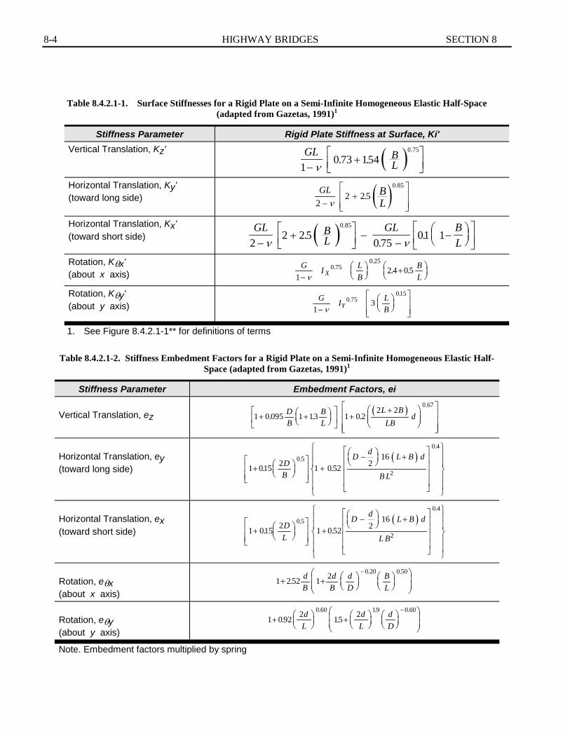
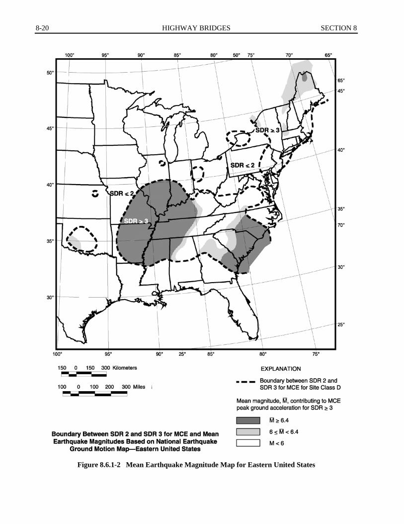
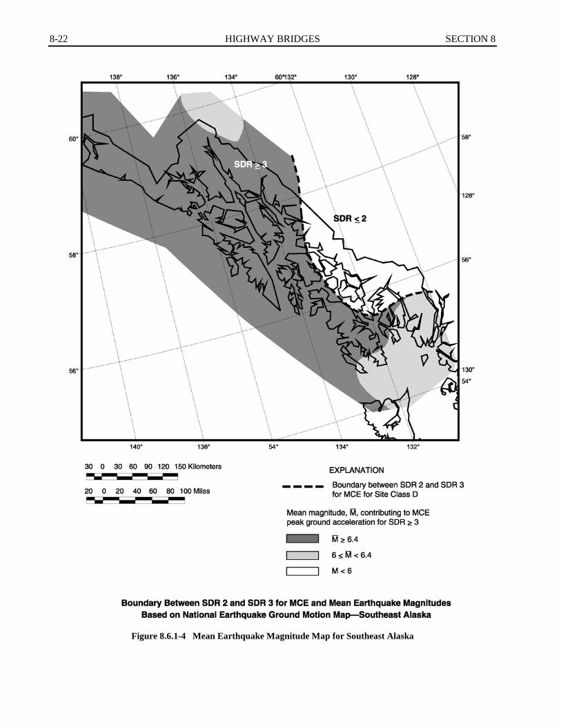
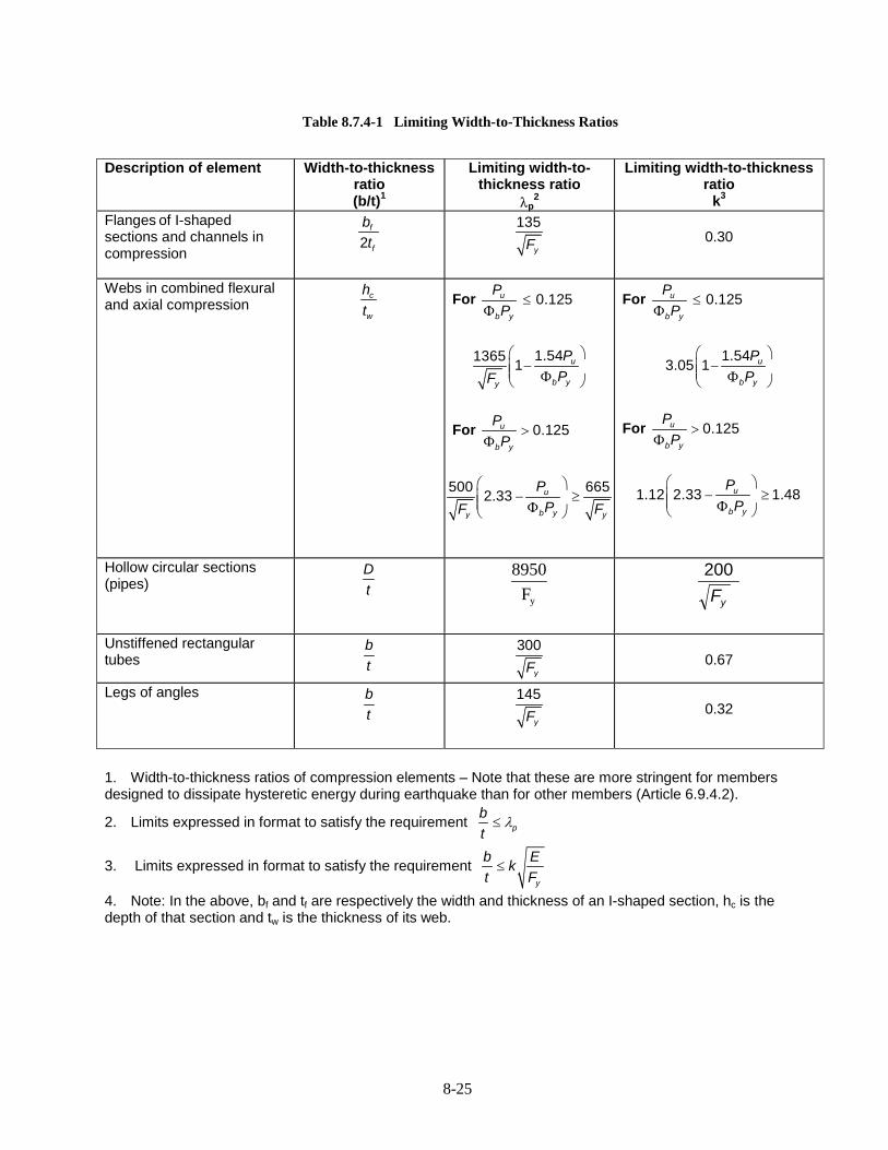
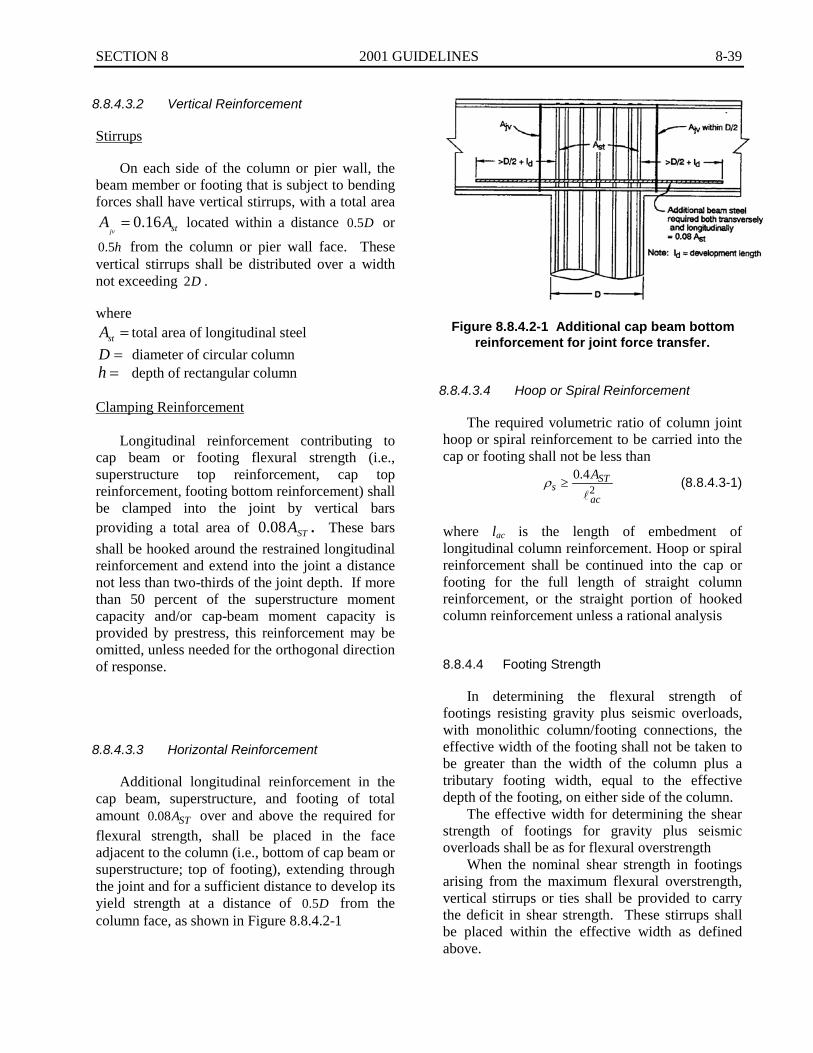