Embed Size (px)
Citation preview
SECTION 700 ROADWAY DESIGN, TRAFFIC CONTROL DEVICES AND STREET
LIGHTING
701.00 GENERAL CONDITIONS ........................................................................ 4 710.00 SCOPE ........................................................................................................ 4
710.01 Roadway Inspections ..................................................................................... 4 720.00 ROADWAY DESIGN ............................................................................... 4
721.00 Planning Principles for Local Circulation Systems ............................................. 4 721.01 Local Type I (gravel) ..................................................................................... 6 721.02 Local Type II .................................................................................................. 8 721.03 Local Type III .............................................................................................. 10 721.04 Local Type IV Commercial & Industrial ..................................................... 12
722.00 Collector............................................................................................................. 14 722.01 Minor Collector ............................................................................................ 14 722.02 Major Collector ............................................................................................ 15
723.00 Arterial ............................................................................................................... 18 723.01 Minor Arterial .............................................................................................. 18 723.02 Major Arterial (4 Lane) ................................................................................ 20 723.03 Major Arterial (6 Lane) ................................................................................ 22
724.00 Rural Roads........................................................................................................ 24 724.01 Rural Local Type V ..................................................................................... 24 724.02 Rural Local Type VI .................................................................................... 26 724.03 Rural Local/Collector ................................................................................... 28 724.04 Rural Major Collector .................................................................................. 30
725.00 Major Structures ................................................................................................ 40 726.00 Emergency Access ............................................................................................. 40 727.00 Parking Lots and Private Street Systems ........................................................... 40 728.00 Street Lane Design Criteria ................................................................................ 41
728.01 Acceleration and Deceleration Lanes .......................................................... 41 728.02 Required Turning Lane Length .................................................................... 41 728.03 Redirect Tapers for Through Lanes ............................................................. 41 728.04 Entering Sight Distance ............................................................................... 41 728.05 Roundabouts ................................................................................................ 42
729.00 Structural Sections ............................................................................................. 42 729.01 Structural Sections for Streets ...................................................................... 42 729.02 Structural Sections for Parking Lots ............................................................ 43 729.03 Structural Sections for Reconstruction of Existing Low Volume Roadways
....................................................................................................................... 43 729.04 Edge Drains .................................................................................................. 45
730.00 SIGNAGE AND PAVEMENT MARKINGS .......................................... 46 731.00 Signs................................................................................................................... 46
731.01 Street Name Signs ........................................................................................ 46 731.02 Illuminated Signs ......................................................................................... 46 731.03 Stop Signs .................................................................................................... 48 731.04 Other Signs ................................................................................................... 48
ROADWAY DESIGN, TRAFFIC CONTROL DEVICES AND STREET LIGHTING SECTION 700
CONSTRUCTION STANDARDS & SPECIFICATIONS 2019 Edition PAGE 700-2
731.05 ‘No Parking’ Signs ....................................................................................... 48 731.06 Sign Dimensions .......................................................................................... 48 731.07 Sign Installation ........................................................................................... 49
732.00 Sign Posts and Support Posts ............................................................................. 49 733.00 Pavement Markings ........................................................................................... 49
733.01 General ......................................................................................................... 50 733.02 Typical Pavement Markings ........................................................................ 50 733.03 Typical Crosswalks and Stop Bars .............................................................. 50 733.04 Crosswalks and Stop Bars at Signalized Intersections or Mid-Crossings ... 50 733.05 Surface Preparation ...................................................................................... 50 733.06 Prior to Placement of Pavement Marking Materials .................................... 51 733.07 Placement of Pavement Markings................................................................ 51
740.00 TRAFFIC SIGNALS ................................................................................ 52 741.00 Control of Work ................................................................................................. 52
741.01 Regulations and Code .................................................................................. 52 741.02 Inspection ..................................................................................................... 52 741.03 Traffic Control ............................................................................................. 56 741.04 Equipment List and Drawings ..................................................................... 56 741.05 Coordination with Other Agencies and Contractors .................................... 56 741.06 Signal Pole and Signal Head Colors ............................................................ 56
742.00 Conduit............................................................................................................... 57 742.01 General ......................................................................................................... 57 742.02 Materials ...................................................................................................... 57 742.03 Installation .................................................................................................... 57
743.00 Cable and Conductors ........................................................................................ 59 743.01 General ......................................................................................................... 59 743.02 Multiconductor Cable .................................................................................. 59 743.03 Wiring Installation ....................................................................................... 59 743.04 Connections to Signal Heads, Pushbutton Switches and Traffic Controllers
....................................................................................................................... 60 743.05 Wire Splicing Locations .............................................................................. 60 743.06 Wire Bonding and Grounding ...................................................................... 60
744.00 Electric Service Connection............................................................................... 60 745.00 Concrete Foundations ........................................................................................ 61
745.01 General ......................................................................................................... 61 745.02 Poles, Standards and Pedestal Foundations ................................................. 61
746.00 Traffic Signal Controllers .................................................................................. 61 746.01 Signal Phasing and Tape Colors .................................................................. 61 746.02 Controller Type ........................................................................................... 62 746.03 Cabinet Type ................................................................................................. 62 746.04 Signal Cabinet Base ..................................................................................... 64 746.05 Signal Cabinet Locations ............................................................................. 64 746.06 Cycle Length ................................................................................................ 64 746.07 Spread Spectrum .......................................................................................... 64 747.08 Uninterruptible Power System ..................................................................... 65 746.09 Video Detection System .............................................................................. 68
747.00 Light Emitting Diode (LED) Lights .................................................................. 71
ROADWAY DESIGN, TRAFFIC CONTROL DEVICES AND STREET LIGHTING SECTION 700
CONSTRUCTION STANDARDS & SPECIFICATIONS 2019 Edition PAGE 700-3
747.01 Wattage ........................................................................................................ 71 747.02 Voltage ......................................................................................................... 71 747.03 Circuit Configuration ................................................................................... 72 747.04 Enclosure ...................................................................................................... 72 747.05 Operating Temperature ................................................................................ 72 747.06 Lens .............................................................................................................. 72 747.07 Candlepower Distribution ............................................................................ 72 747.08 Beam Spread ................................................................................................ 72 747.09 Manufacturer’s Warranty ............................................................................. 72
748.00 Speed Monitor Display (Speed Awareness Sign) .............................................. 72 748.01 Size ............................................................................................................... 73 748.02 Programming ................................................................................................ 73 748.03 Violator Alert ............................................................................................... 73 748.04 Radar Unit .................................................................................................... 73
749.00 Traffic Signal Start-Up Procedures.................................................................... 73 750.00 STREET LIGHTING ............................................................................... 73
751.00 Street Lighting Procedure .................................................................................. 73 760.00 PRIVATE DRIVEWAY DESIGN SPECIFICATIONS .......................... 74
761.00 Width: ................................................................................................................ 74 762.00 Vertical Clearance: ............................................................................................ 74 763.00 Surface – Sub-Base: .......................................................................................... 74
763.01 Aggregate surface – sub-base. ..................................................................... 75 763.02 Driveways accessing paved Elbert County/private roads. ........................... 75
764.00 Approach:.......................................................................................................... 75 765.00 Turning Radii: .................................................................................................... 76 766.00 Slope: ................................................................................................................. 78 767.00 Bridges And Water Crossings: .......................................................................... 79 768.00 Livestock Crossings: ......................................................................................... 79 769.00 Gates and Limited Access Appliances: ............................................................. 79
770.00 COMMERCIAL DRIVEWAY REQUIREMENTS ................................ 80 771.00 Width: ................................................................................................................ 80 772.00 Surface: .............................................................................................................. 80 773.00 Approach:......................................................................................................... 80 774.00 Culverts ............................................................................................................. 80 775.00 Paved surfaces................................................................................................... 81
780.00 CULVERTS ............................................................................................ 81
ROADWAY DESIGN, TRAFFIC CONTROL DEVICES AND STREET LIGHTING SECTION 700
CONSTRUCTION STANDARDS & SPECIFICATIONS 2019 Edition PAGE 700-4
SECTION 700 ROADWAY DESIGN, TRAFFIC CONTROL DEVICES AND STREET
LIGHTING 701.00 GENERAL CONDITIONS Refer to Section 100 Title, Scope And General Conditions of these CONSTRUCTION STANDARDS & SPECIFICATIONS for additional requirements that apply to all projects within Elbert County. This section sets forth the minimum design and technical criteria and specifications to be used in the preparation of all roadway plans. 710.00 SCOPE All residential and commercial/industrial developments shall provide a Traffic Analysis Report that complies with Section 16.00 Engineering Reports of these CONSTRUCTION STANDARDS & SPECIFICATIONS. All requirements of Elbert County’s Subdivision and Zoning Ordinances shall be met. Roadway design and R.O.W. modifications shall conform to AASHTO: A Policy on Geometric Design of Highways and Streets, these CONSTRUCTION STANDARS & SPECIFICATIONS and any other requirements determined by Elbert County. The design and installation of traffic control devices and street lighting shall comply with all applicable portions of the latest edition of the CDOT Standard Specifications for Road and Bridge Construction, the latest edition of the Manual on Uniform Traffic Control Devices (MUTCD), these CONSTRUCTION STANDARS & SPECIFICATIONS and any other requirements determined by the DPW Director or designee.
710.01 Roadway Inspections
Refer to Section 154.00 Inspections and Section 931.00 Roadway Inspections of these CONSTRUCTION STANDARDS & STANDARDS & SPECIFICATIONS for required inspections during roadway construction.
720.00 ROADWAY DESIGN Roadway Design and Technical Criteria Elbert County has identified a Functional Street Classification Plan based on traffic volumes, land use and expected growth. This Functional Street Classification Plan designates streets as local (Types I, II, III & IV), collector (major and minor), arterial (major and minor). The following criteria apply to each classification.
721.00 Planning Principles for Local Circulation Systems
ROADWAY DESIGN, TRAFFIC CONTROL DEVICES AND STREET LIGHTING SECTION 700
CONSTRUCTION STANDARDS & SPECIFICATIONS 2019 Edition PAGE 700-5
Basic considerations in the design of local circulation systems must recognize the following factors:
Safety – for both vehicular and pedestrian traffic
Efficiency of Service –for all users Livability – especially as affected by traffic elements in the circulation system Economy – of both construction and use of land
Each of the following principles is an elaboration on one or more of these four factors. The principles are not intended as absolute criteria, since instances may appear where certain principles conflict. The principles should, therefore, be used as guides to proper systems layout.
Ensure Vehicular and Pedestrian Access
The primary function of local streets is to serve abutting properties. Street widths, placement of sidewalks, patterns of street and number of intersections are related to safe and efficient access to abutting lands.
Minimize Through Trips Through traffic on local and collector streets increases the average speed and volume and thus the accident potential, thereby reducing residential amenities. Through traffic can be discouraged by creating a circuitous route between neighborhoods and higher volume streets and by channelizing or controlling median crossings along peripheral routes.
Control Access to Arterials Local circulation systems and land development patterns should not detract from the efficiency of peripheral arterial facilities. Ideally, land development should occur so that no local streets require direct access to arterial routes. The number of access points between the local circulation system and the arterial routes should be properly spaced for efficient signalization and traffic flow. The streets that do intersect the arterial system will tend to have high volumes since they are the only exit points.
Discourage Speeding Residential streets should be designed to discourage fast movement (more than 25 M.P.H.), through the use of curvilinear alignments and circuitous routes in the street system.
Minimize Pedestrian – Vehicular Conflicts Pedestrian travel from within the area to points outside should require a minimum of street crossings. Sometimes this may be achieved through proper design of street patterns, land arrangements and pedestrian routes. Typical methods include use of cul-de-sacs and loop streets, special pedestrian routes or walkways and the proper placement of high pedestrian traffic generators. In general, while vehicular flow must be outward oriented to the peripheral arterials, pedestrian travel should be inward-oriented to avoid these heavier vehicular flows.
ROADWAY DESIGN, TRAFFIC CONTROL DEVICES AND STREET LIGHTING SECTION 700
CONSTRUCTION STANDARDS & SPECIFICATIONS 2019 Edition PAGE 700-6
Minimize Space Devoted to Street Use It is desirable to minimize local street mileage to reduce construction and maintenance costs as well as to permit the most economic land use. Street should also have an appearance commensurate with their function. They should be in keeping with the residential character.
Relate Street to Topography Local streets will be more attractive and economical if they are constructed to closely adhere to topography. The important role that streets play in the overall storm drainage system can be enhanced by using the topography of the area.
Layout Street to Achieve Optimum Subdivision of Land The arrangements of streets should permit economical and practical patterns, shapes and sizes of development parcels. Streets as a function of land use must not unduly hinder the development of land. Distances between streets, number of streets, and related elements all have a bearing on efficient subdivision of an area. Access to adjoining properties should also be encouraged, and in some cases may be required Any subdivision of land greater than seven (7) lots will require two (2) points of access/egress unless otherwise specified. A subdivision of land that includes greater than seven (7) lots will be required to pave the roadway(s) within the subdivision when accessed from an existing County maintained paved roadway regardless if the subdivision roadway(s) are public or private. Subdivision applications for properties that are contiguous to an existing platted subdivision(s) and utilizing roadways through such subdivision(s) or share adjacent roads will be analyzed using the combined density of both subdivisions. This will generally require paving of the roadway(s) through the combined communities. (Example: an application for a seven (7) lot subdivision adjacent to and utilizing or sharing access to a five (5) lot subdivision will be evaluated as a twelve (12) lot subdivision). Elbert County Public Works reserves the right to accept or reject any roadway not constructed in compliance with County specifications. Elbert County discourages the construction of gravel roadways in a platted subdivision with greater than seven (7) lots. A subdivision of three (3) lots or less will be reviewed on a case by case basis.
721.01 Local Type I (gravel)
a Posted Speed Limit – 25
Posted or prima facie speeds for the various street classifications shall be 5 miles per hour less than the design speed of that street.
ROADWAY DESIGN, TRAFFIC CONTROL DEVICES AND STREET LIGHTING SECTION 700
CONSTRUCTION STANDARDS & SPECIFICATIONS 2019 Edition PAGE 700-7
b Traffic Volumes
Less than 200 vehicles per day.
c Limited Continuity d Safety
Designed for the ease of access to adjacent parcels of land.
e Traffic Control Stop signs.
f Function
Local streets provide direct access to adjacent property. Traffic carried by local streets should have an origin or a destination within the neighborhood. 10’utility, snow storage, and Signage easements shall be dedicated. When intersecting with paved road, pavement shall extend to right-of way.
g Right-of-Way
60 feet
h Number of Moving Lanes Two
i Access Conditions Intersections at grade with direct access to abutting property permitted.
j Planning Characteristic
Local Streets should be designed to discourage through traffic from moving through the neighborhood. Local streets should not intersect major collectors or arterial streets. This category of Local Street shall be for residential developments. No on-street parking shall be allowed.
k Type of Curb and Gutter
None. Gravel shoulders.
l Cul-De-Sacs
ROADWAY DESIGN, TRAFFIC CONTROL DEVICES AND STREET LIGHTING SECTION 700
CONSTRUCTION STANDARDS & SPECIFICATIONS 2019 Edition PAGE 700-8
Shall all have a minimum driving radius of fifty (50) feet, and can be no longer than 600 feet in length, unless a secondary access is provided.
m Sidewalk Width
None required.
n Street Widths
Single-family residential; 24’ graveled width plus 2-4’ gravel shoulders, parking restricted on both sides.
o Minimum Radius or Curvature on Centerline (Horizontal)
See Table 7.2
p Minimum Length of Vertical Curves See Table 7.5
q Street Grades
A minimum longitudinal centerline grade of 2.0% shall be required on all Local streets. Maximum grade is 8.0%. See Table 7.1.
r Curb Return Radii No curb returns however, asphalt radius at intersections shall comply with Table If a gravel road intersects or has access off of a paved County maintained roadway the gravel road shall have a full width paved apron tying into the paved roadway 50 feet beyond the PCR from where the gravel road intersects the County roadway-maintained roadway. Subdivisions with greater than (7) lots will be required to pave the entire roadway(s) within that subdivision.
721.02 Local Type II
a Posted Speed Limit
25 mph minimum. Posted or prima facie speeds for the various street classifications shall be 5 miles per hour less than the design speed of that street.
b Traffic Volumes
ROADWAY DESIGN, TRAFFIC CONTROL DEVICES AND STREET LIGHTING SECTION 700
CONSTRUCTION STANDARDS & SPECIFICATIONS 2019 Edition PAGE 700-9
Stop signs.
c Limited Continuity
d Safety Designed for ease of access to adjacent parcels of land.
e Traffic Control Less than 1,280 vehicles per day or 160 dwelling units.
f Function
Local streets provide direct access to adjacent property. Traffic carried by local streets should have an origin of a destination within the neighborhood. Utility, snow storage, and signage easements shall be dedicated.
g Right-of-Way
50 feet with curb and gutter, 60 feet gravel shoulders.
h Number of Moving Lanes Two
i Access Conditions Intersections at grade with direct access to abutting property permitted.
j Planning Characteristics
Local streets should be designed to discourage through traffic from moving through the neighborhood. This category of Local Street shall be for residential developments. No on street parking shall be allowed.
k Type of Curb and Gutter
Mountable type curb.
l Cul-De-Sacs
ROADWAY DESIGN, TRAFFIC CONTROL DEVICES AND STREET LIGHTING SECTION 700
CONSTRUCTION STANDARDS & SPECIFICATIONS 2019 Edition PAGE 700-10
Shall all have a minimum radius of fifty (50’) feet to flow line or EOA (See Exhibits SP.21b and SP.21c) and can be no longer than 600 feet in length, unless a secondary access is provided.
m Sidewalk Width
None required.
n Street Width
Single-family residential; 24’ paved width plus 2-4’ gravel shoulders or 24’ flowline – flowline ((20’ paved width plus 2-2’ gutter pans) with parking restricted on both sides.
o Minimum Radius of Curvature on Centerline (Horizontal)
See Table 7.2
p Minimum Length of Vertical Curves See Table 7.5
q Street Grades
A minimal longitudinal flowline grade of 1.0% shall be required on all Local streets. See Table 7.1.
r Curb Return Radii
See Table 7.3.
721.03 Local Type III
a POSTED SPEED LIMIT – 25 mph
Posted or prima facie speeds for the various street classifications shall be 5 miles per hour less than the design speed of that street.
b TRAFFIC VOLUMES
Less than 1500 vehicles per day.
c LIMITED CONTINUITY
d SAFETY
ROADWAY DESIGN, TRAFFIC CONTROL DEVICES AND STREET LIGHTING SECTION 700
CONSTRUCTION STANDARDS & SPECIFICATIONS 2019 Edition PAGE 700-11
Designed for the safety of pedestrians and bicyclist, and the ease of access to adjacent parcels of land.
e TRAFFIC CONTROL
Stop signs, yield signs, or right-of way rules for uncontrolled intersections.
f FUNCTION
Local streets provide direct access to adjacent property. Traffic carried by local streets should have an origin or a destination within the neighborhood. Utility line easements should be available.
g RIGHT-OF-WAY – 50 feet
h NUMBER OF MOVING LANES – Two
i ACCESS CONDITIONS
Intersections at grade with direct access to abutting property permitted.
j PLANNING CHARACTERISTICS
Local streets should be designed to discourage through traffic from moving through the neighborhood.
k TYPE OF CURB AND GUTTER
Mountable type with attached sidewalk.
l CUL-DE-SACS, KNUCKLES, & EYEBROWS
Shall all have a minimum flowline radius of forty-five (45) feet. Cul-de-sacs can be no longer than 600 feet in length, unless a secondary assess is provided, or with more than 25 dwelling units, may require all units to be sprinkled per NFPA-13D.
m SIDEWALK WIDTH
Single-family residential: 4’ wide combination w/curb.
n STREET WIDTHS
Single – family residential: 24’ paved width plus 2-2’ gutter pans. (28’ flowline – flowline with parking restricted on one side.)
ROADWAY DESIGN, TRAFFIC CONTROL DEVICES AND STREET LIGHTING SECTION 700
CONSTRUCTION STANDARDS & SPECIFICATIONS 2019 Edition PAGE 700-12
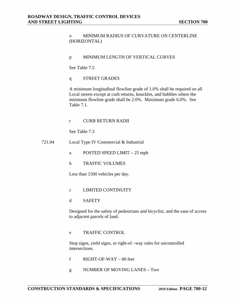
o MINIMUM RADIUS OF CURVATURE ON CENTERLINE (HORIZONTAL)
p MINIMUM LENGTH OF VERTICAL CURVES See Table 7.5
q STREET GRADES
A minimum longitudinal flowline grade of 1.0% shall be required on all Local streets except at curb returns, knuckles, and bubbles where the minimum flowline grade shall be 2.0%. Maximum grade 6.0%. See Table 7.1.
r CURB RETURN RADII See Table 7.3
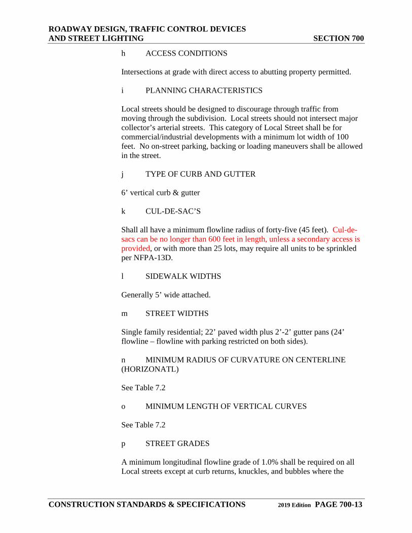
721.04 Local Type IV Commercial & Industrial
a POSTED SPEED LIMIT – 25 mph
b TRAFFIC VOLUMES
Less than 1500 vehicles per day.
c LIMITED CONTINUITY
d SAFETY
Designed for the safety of pedestrians and bicyclist, and the ease of access to adjacent parcels of land.
e TRAFFIC CONTROL
Stop signs, yield signs, or right-of –way rules for uncontrolled intersections.
f RIGHT-OF-WAY – 60 feet
g NUMBER OF MOVING LANES – Two
ROADWAY DESIGN, TRAFFIC CONTROL DEVICES AND STREET LIGHTING SECTION 700
CONSTRUCTION STANDARDS & SPECIFICATIONS 2019 Edition PAGE 700-13
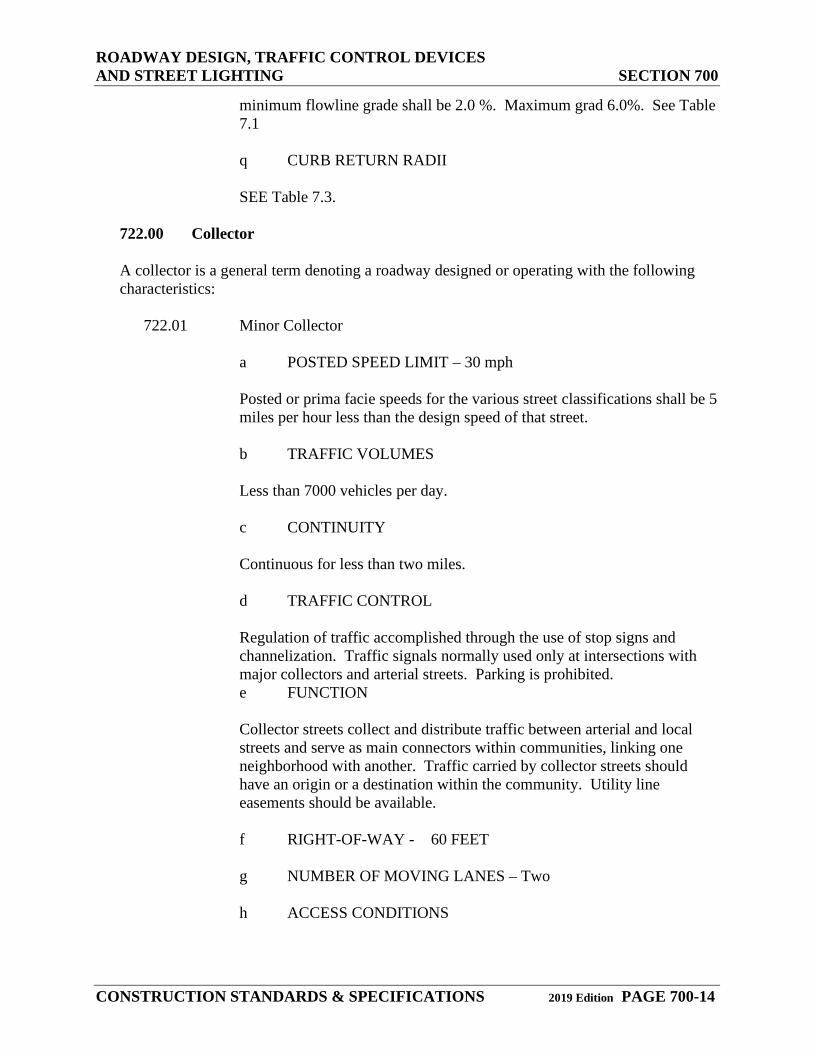
h ACCESS CONDITIONS
Intersections at grade with direct access to abutting property permitted.
i PLANNING CHARACTERISTICS
Local streets should be designed to discourage through traffic from moving through the subdivision. Local streets should not intersect major collector’s arterial streets. This category of Local Street shall be for commercial/industrial developments with a minimum lot width of 100 feet. No on-street parking, backing or loading maneuvers shall be allowed in the street.
j TYPE OF CURB AND GUTTER
6’ vertical curb & gutter
k CUL-DE-SAC’S
Shall all have a minimum flowline radius of forty-five (45 feet). Cul-de-sacs can be no longer than 600 feet in length, unless a secondary access is provided, or with more than 25 lots, may require all units to be sprinkled per NFPA-13D.
l SIDEWALK WIDTHS
Generally 5’ wide attached.
m STREET WIDTHS
Single family residential; 22’ paved width plus 2’-2’ gutter pans (24’ flowline – flowline with parking restricted on both sides). n MINIMUM RADIUS OF CURVATURE ON CENTERLINE (HORIZONATL)
See Table 7.2
o MINIMUM LENGTH OF VERTICAL CURVES See Table 7.2
p STREET GRADES
A minimum longitudinal flowline grade of 1.0% shall be required on all Local streets except at curb returns, knuckles, and bubbles where the
ROADWAY DESIGN, TRAFFIC CONTROL DEVICES AND STREET LIGHTING SECTION 700
CONSTRUCTION STANDARDS & SPECIFICATIONS 2019 Edition PAGE 700-14
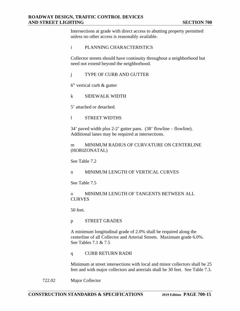
minimum flowline grade shall be 2.0 %. Maximum grad 6.0%. See Table 7.1
q CURB RETURN RADII
SEE Table 7.3.
722.00 Collector
A collector is a general term denoting a roadway designed or operating with the following characteristics:
722.01 Minor Collector
a POSTED SPEED LIMIT – 30 mph
Posted or prima facie speeds for the various street classifications shall be 5 miles per hour less than the design speed of that street.
b TRAFFIC VOLUMES
Less than 7000 vehicles per day.
c CONTINUITY Continuous for less than two miles.
d TRAFFIC CONTROL
Regulation of traffic accomplished through the use of stop signs and channelization. Traffic signals normally used only at intersections with major collectors and arterial streets. Parking is prohibited. e FUNCTION
Collector streets collect and distribute traffic between arterial and local streets and serve as main connectors within communities, linking one neighborhood with another. Traffic carried by collector streets should have an origin or a destination within the community. Utility line easements should be available.
f RIGHT-OF-WAY - 60 FEET
g NUMBER OF MOVING LANES – Two
h ACCESS CONDITIONS
ROADWAY DESIGN, TRAFFIC CONTROL DEVICES AND STREET LIGHTING SECTION 700
CONSTRUCTION STANDARDS & SPECIFICATIONS 2019 Edition PAGE 700-15
Intersections at grade with direct access to abutting property permitted unless no other access is reasonably available.
i PLANNING CHARACTERISTICS
Collector streets should have continuity throughout a neighborhood but need not extend beyond the neighborhood.
j TYPE OF CURB AND GUTTER
6” vertical curb & gutter
k SIDEWALK WIDTH 5’ attached or detached.
l STREET WIDTHS
34’ paved width plus 2-2’ gutter pans. (38’ flowline – flowline). Additional lanes may be required at intersections.
m MINIMUM RADIUS OF CURVATURE ON CENTERLINE (HORIZONATAL)
See Table 7.2
n MINIMUM LENGTH OF VERTICAL CURVES
See Table 7.5
o MINIMUM LENGTH OF TANGENTS BETWEEN ALL CURVES
50 feet.
p STREET GRADES
A minimum longitudinal grade of 2.0% shall be required along the centerline of all Collector and Arterial Streets. Maximum grade 6.0%. See Tables 7.1 & 7.5
q CURB RETURN RADII
Minimum at street intersections with local and minor collectors shall be 25 feet and with major collectors and arterials shall be 30 feet. See Table 7.3.
722.02 Major Collector
ROADWAY DESIGN, TRAFFIC CONTROL DEVICES AND STREET LIGHTING SECTION 700
CONSTRUCTION STANDARDS & SPECIFICATIONS 2019 Edition PAGE 700-16
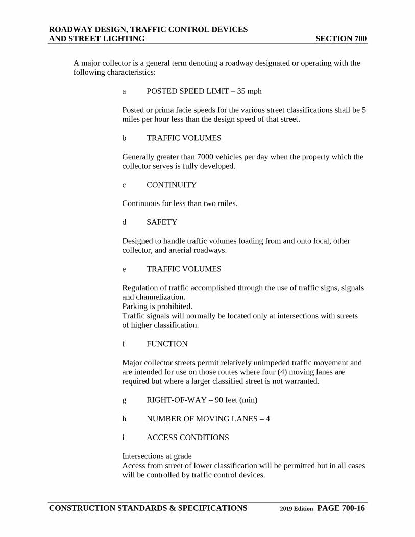
A major collector is a general term denoting a roadway designated or operating with the following characteristics:
a POSTED SPEED LIMIT – 35 mph
Posted or prima facie speeds for the various street classifications shall be 5 miles per hour less than the design speed of that street.
b TRAFFIC VOLUMES
Generally greater than 7000 vehicles per day when the property which the collector serves is fully developed.
c CONTINUITY
Continuous for less than two miles.
d SAFETY
Designed to handle traffic volumes loading from and onto local, other collector, and arterial roadways.
e TRAFFIC VOLUMES
Regulation of traffic accomplished through the use of traffic signs, signals and channelization.
Parking is prohibited. Traffic signals will normally be located only at intersections with streets of higher classification.
f FUNCTION
Major collector streets permit relatively unimpeded traffic movement and are intended for use on those routes where four (4) moving lanes are required but where a larger classified street is not warranted.
g RIGHT-OF-WAY – 90 feet (min)
h NUMBER OF MOVING LANES – 4
i ACCESS CONDITIONS
Intersections at grade
Access from street of lower classification will be permitted but in all cases will be controlled by traffic control devices.
ROADWAY DESIGN, TRAFFIC CONTROL DEVICES AND STREET LIGHTING SECTION 700
CONSTRUCTION STANDARDS & SPECIFICATIONS 2019 Edition PAGE 700-17
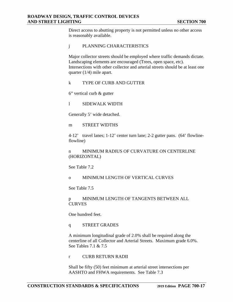
Direct access to abutting property is not permitted unless no other access is reasonably available.
j PLANNING CHARACTERISTICS
Major collector streets should be employed where traffic demands dictate. Landscaping elements are encouraged (Trees, open space, etc). Intersections with other collector and arterial streets should be at least one quarter (1/4) mile apart.
k TYPE OF CURB AND GUTTER
6” vertical curb & gutter
l SIDEWALK WIDTH Generally 5’ wide detached.
m STREET WIDTHS 4-12’ travel lanes; 1-12’ center turn lane; 2-2 gutter pans. (64’ flowline-
flowline)
n MINIMUM RADIUS OF CURVATURE ON CENTERLINE (HORIZONTAL)
See Table 7.2
o MINIMUM LENGTH OF VERTICAL CURVES See Table 7.5
p MINIMUM LENGTH OF TANGENTS BETWEEN ALL CURVES
One hundred feet.
q STREET GRADES
A minimum longitudinal grade of 2.0% shall be required along the centerline of all Collector and Arterial Streets. Maximum grade 6.0%. See Tables 7.1 & 7.5
r CURB RETURN RADII
Shall be fifty (50) feet minimum at arterial street intersections per AASHTO and FHWA requirements. See Table 7.3
ROADWAY DESIGN, TRAFFIC CONTROL DEVICES AND STREET LIGHTING SECTION 700
CONSTRUCTION STANDARDS & SPECIFICATIONS 2019 Edition PAGE 700-18
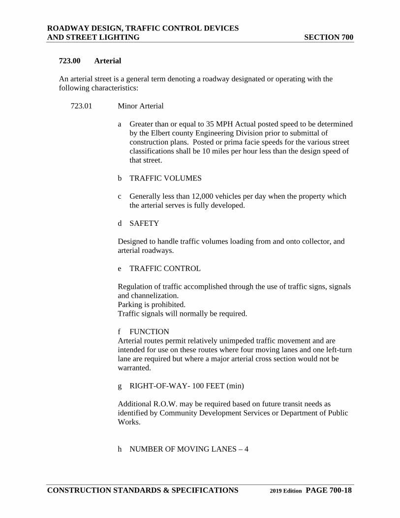
723.00 Arterial
An arterial street is a general term denoting a roadway designated or operating with the following characteristics:
723.01 Minor Arterial
a Greater than or equal to 35 MPH Actual posted speed to be determined
by the Elbert county Engineering Division prior to submittal of construction plans. Posted or prima facie speeds for the various street classifications shall be 10 miles per hour less than the design speed of that street.
b TRAFFIC VOLUMES
c Generally less than 12,000 vehicles per day when the property which
the arterial serves is fully developed.
d SAFETY
Designed to handle traffic volumes loading from and onto collector, and arterial roadways.
e TRAFFIC CONTROL
Regulation of traffic accomplished through the use of traffic signs, signals and channelization.
Parking is prohibited. Traffic signals will normally be required.
f FUNCTION Arterial routes permit relatively unimpeded traffic movement and are intended for use on these routes where four moving lanes and one left-turn lane are required but where a major arterial cross section would not be warranted.
g RIGHT-OF-WAY- 100 FEET (min)
Additional R.O.W. may be required based on future transit needs as identified by Community Development Services or Department of Public Works.
h NUMBER OF MOVING LANES – 4
ROADWAY DESIGN, TRAFFIC CONTROL DEVICES AND STREET LIGHTING SECTION 700
CONSTRUCTION STANDARDS & SPECIFICATIONS 2019 Edition PAGE 700-19
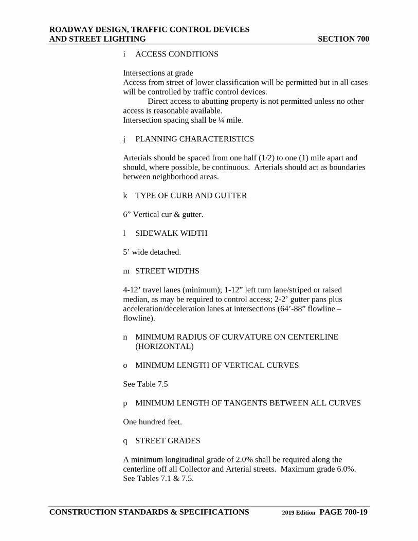
i ACCESS CONDITIONS Intersections at grade
Access from street of lower classification will be permitted but in all cases will be controlled by traffic control devices. Direct access to abutting property is not permitted unless no other access is reasonable available.
Intersection spacing shall be ¼ mile.
j PLANNING CHARACTERISTICS
Arterials should be spaced from one half (1/2) to one (1) mile apart and should, where possible, be continuous. Arterials should act as boundaries between neighborhood areas.
k TYPE OF CURB AND GUTTER
6” Vertical cur & gutter.
l SIDEWALK WIDTH 5’ wide detached.
m STREET WIDTHS
4-12’ travel lanes (minimum); 1-12” left turn lane/striped or raised median, as may be required to control access; 2-2’ gutter pans plus acceleration/deceleration lanes at intersections (64’-88” flowline – flowline).
n MINIMUM RADIUS OF CURVATURE ON CENTERLINE
(HORIZONTAL) o MINIMUM LENGTH OF VERTICAL CURVES
See Table 7.5
p MINIMUM LENGTH OF TANGENTS BETWEEN ALL CURVES
One hundred feet.
q STREET GRADES
A minimum longitudinal grade of 2.0% shall be required along the centerline off all Collector and Arterial streets. Maximum grade 6.0%. See Tables 7.1 & 7.5.
ROADWAY DESIGN, TRAFFIC CONTROL DEVICES AND STREET LIGHTING SECTION 700
CONSTRUCTION STANDARDS & SPECIFICATIONS 2019 Edition PAGE 700-20
r CURB RETURN RADII
Shall be fifty (50) feet minimum at arterial street intersections per AASHTO and FHWA requirements. See Table 7.3.
723.02 Major Arterial (4 Lane)
a POSTED SPEED LIMIT – Greater than or equal to 35 MPH
Actual posted speed to be determined by Elbert County Road & Bridge prior to submittal of construction plans. Posted or prima facie speeds for the various street classifications shall be 10 miles per hour less than the design speed of that street.
b TRAFFIC VOLUMES
Generally greater than 12,000 vehicles per day when the property which the collector serves is fully developed.
c CONTINUITY
Continuous for several miles, generally connecting with inter-county and intra-county routes.
d SAFETY
Major arterial streets permit rapid and relatively unimpeded traffic movement throughout the county, connecting major land use elements as well as communities with one another. Designed to handle traffic volumes loading from and onto collector, and arterial roadways.
e TRAFFIC CONTROL Regulation of traffic accomplished through the use of traffic signals and channelization.
Parking shall be prohibited. Roadways should have a median strip between them.
f FUNCTION
Major arterial routes permit rapid and relatively unimpeded traffic movement throughout the county, connecting major land use elements as well as communities with one another.
g RIGHT-OF-WAY – 120 feet (min)
ROADWAY DESIGN, TRAFFIC CONTROL DEVICES AND STREET LIGHTING SECTION 700
CONSTRUCTION STANDARDS & SPECIFICATIONS 2019 Edition PAGE 700-21
Additional R.O.W. may be required based on future transit needs as identified by Community Development Services or Department of Public Works.
h NUMBER OF MOVING LANES – 4
i ACCESS CONDITIONS
1. Intersections at grade 2. Intersections will normally be located at ¼ mile intervals. 3. Access from collector and arterial streets shall be controlled
by traffic control devices. 4. Normally, direct access to abutting property is not
permitted. 5. Abutting properties should not face on the roadway unless
separated from it by a frontage road.
j PLANNING CHARACTERISTICS
Major arterials should be spaced approximately one (1) mile apart and should traverse an entire city and/or county. Major arterial streets should not bisect neighborhoods but should act as boundaries between them.
k TYPE OF CURB AND GUTTER
6” vertical curb & gutter.
l SIDEWALK WIDTH
5’ wide detached.
m STREET WIDTH
4-12’ travel lanes (minimum); 4’ to 26’ medians, striped or raised median as may be required to control access; 2-1’; median gutter pans plus necessary left turn and acceleration/deceleration lanes and 4’ median at intersections plus 2-2’ gutter pans (80’ – 102’ flowline-flowline).
n MINIMUM RADIUS OF CURVATURE ON CENTERLINE
(HORIZONTAL)
o MINIMUM LENGTH OF VERTICAL CURVES
See Table 7.5
p MINIMUM LENGTH OF TANGENTS BETWEEN ALL CURVES
ROADWAY DESIGN, TRAFFIC CONTROL DEVICES AND STREET LIGHTING SECTION 700
CONSTRUCTION STANDARDS & SPECIFICATIONS 2019 Edition PAGE 700-22
One hundred feet
q STREET GRADES
A minimum longitudinal grade of 2.0% shall be required along the centerline of all Collector and Arterial streets. Maximum grade 6.0%. See Tables 7.1 & 7.5.
r CURB RETURN RADII
Shall be fifty (50) feet minimum at arterial street intersections per AASHTO and FHWA requirements. See Table 7.3.
723.03 Major Arterial (6 Lane)
a POSTED SPEED LIMIT – Greater than or equal to 35 MPH
Actual posted speed to be determined by Elbert County Road & Bridge prior to submittal of construction plans. Posted or prima facie speeds for the various street classifications shall be 10 miles per hour less than the design speed of that street.
b TRAFFIC VOLUMES
Generally greater than 12,000 vehicles per day when the property which the collector serves is fully developed.
c CONTINUITY
Continuous for several miles, generally connecting with inter county and intra-county routes.
d SAFETY
Major arterial streets permit rapid and relatively unimpeded traffic movement throughout the county, connecting major land use elements as well as communities with one another. Designed to handle traffic volumes loading from and onto collector, and arterial roadways.
e TRAFFIC CONTROL
Regulation of traffic accomplished through the use of traffic signals and channelization.
Parking shall be prohibited. Roadways should have a median strip between them.
f FUNCTION
ROADWAY DESIGN, TRAFFIC CONTROL DEVICES AND STREET LIGHTING SECTION 700
CONSTRUCTION STANDARDS & SPECIFICATIONS 2019 Edition PAGE 700-23
Major arterial routes permit rapid and relatively unimpeded traffic movement throughout the county, connection major land use elements as well as communities with one another.\
g RIGHT-OF-WAY – 140 feet (min)
Additional R.O.W. may be required based on future transit needs as identified by the Planning Department.
h NUMBER OF MOVING LANES – 6
i ACCESS CONDITIONS
Intersections will generally be at grade
Intersections will normally be located at ¼ mile intervals Access from collector and arterial streets shall be controlled by traffic control devices.
Normally, direct access to abutting property is not permitted. Abutting properties should not face on the roadway unless separated from it by a frontage road.
j PLANNING CHARACTERISTICS
Major arterials should be spaced approximately one (1) mile apart and should traverse an entire city and/or county. See Section 13.2 for intersection spacing criteria. Major arterial streets should no bisect neighborhoods but should act as boundaries between them.
k TYPE OF CURB AND GUTTER
6” vertical curb & gutter.
l SIDEWALK WIDTH 5’ wide detached.
m STREET WIDTHS
6-12” travel lanes (minimum); 4’ to 26’ medians, striped or raised median as may be required to control access; 2-1’, median gutter pans plus necessary left turn and acceleration/deceleration lanes and 4’ median at intersections plus 2-2’ gutter pans (104’-126’ flowline-flowline).
n MINIMUM RADIUS OF CURVATURE ON CENTERLINE (HORIZONTAL)
ROADWAY DESIGN, TRAFFIC CONTROL DEVICES AND STREET LIGHTING SECTION 700
CONSTRUCTION STANDARDS & SPECIFICATIONS 2019 Edition PAGE 700-24
650’. See Table 7.2.
o MINIMUM LENGTH OF VERTICAL CURVES
See Table 7.5
p MINIMUM LENGTH OF TANGENTS BETWEEN ALL CURVES
One hundred feet
q STREET GRADES
A minimum longitudinal grade of 2.0% shall be required along the centerline of all Collector and Arterial streets. Maximum grade 6.0%. See Tables 7.1 & 7.5.
r CURB RETURN RADII
Shall be fifty (50) feet minimum at arterial street intersections per AASHTO and FHWA requirements. See Table 7.3.
724.00 Rural Roads
Residential developments in rural areas of Elbert County having a lot size of least 2.5 acres (gross) may use the following design criteria;
724.01 Rural Local Type V
a POSTED SPEED LIMIT – 25 mph
Posted or prima facie speeds for the various street classifications shall be 5miles per hour less than the design speed of that street.
b TRAFFIC VOLUMES
Less than 1500 vehicles per day.
c LIMITED CONTINUITY
d SAFETY
Designated for the safety of pedestrians and bicyclists, and the ease of access to adjacent parcels of land.
e TRAFFIC CONTROL
ROADWAY DESIGN, TRAFFIC CONTROL DEVICES AND STREET LIGHTING SECTION 700
CONSTRUCTION STANDARDS & SPECIFICATIONS 2019 Edition PAGE 700-25
Stop signs, yield signs, or right-of –way rules for uncontrolled intersections.
f FUNCTION
Local streets provide direct access to adjacent property. Traffic carried by local streets should have an origin or a destination within the neighborhood. Utility line easements should be provided.
g RIGHT-OF-WAY – 60 feet
h NUMBER OF MOVING LANES - Two
i ACCESS CONDITIONS
Intersections at grade with direct access to abutting property permitted.
j PLANNING CHARACTERISTICS
Local streets should be designed to discourage through traffic from moving through the neighborhood. Local streets should not intersect major collectors or arterial streets. This category of Local Street shall be for residential developments with a minimum lot size of 2.5 acres (gross). No on-street parking shall be allowed.
k TYPE OF CURB AND GUTTER
None. Gravel shoulders.
l CUL-DE-SACS
Shall all have minimum pavement radius of thirty-eight (38) feet. Cul-de sacs can be no longer than 600 feet in length without a secondary access, or with more than 25 dwelling units, may require all units to be sprinkled per NFPA-13D.
m SIDEWALK WIDTHS
None required.
n STREET WIDTHS
Single-family residential; 24’ paved width plus 2-4’ gravel shoulders, parking restricted on both sides.
MINIMUM RADIUS OF CURVATURE ON CENTERLINE (HORIZONTAL)
ROADWAY DESIGN, TRAFFIC CONTROL DEVICES AND STREET LIGHTING SECTION 700
CONSTRUCTION STANDARDS & SPECIFICATIONS 2019 Edition PAGE 700-26
See Table 7.2
o MINIMUM LENGTH OF VERTICAL CURVES
See Table 7.5
p STREET GRADES
A minimum longitudinal flowline grade of 1.0% shall be required on all Local streets except at curb returns, knuckles, and bubbles where the minimum flowline grade shall be 2.0%. Maximum grade 6.0%. See Table 7.1, and Table 7.5.
q CURB RETURN RADII No curb returns, however, asphalt radius at intersections shall comply with Table 7.3.
724.02 Rural Local Type VI
a POSTED SPEED LIMIT – 25 mph
Posted or prima facie speeds for the various street classifications shall be 5 miles per hour less than the design speed of that street.
b TRAFFIC VOLUMES
Less than 1500 vehicles per day.
c LIMITED CONTINUITY
d SAFETY
Designated for the safety of pedestrians and bicyclists, and the ease of access to adjacent parcels of land.
e TRAFFIC CONTROL
Stop signs, yield signs, or right-of-way rules for uncontrolled intersections.
f FUNCTION
Local streets provide direct access to adjacent property. Traffic carried by local streets should have an origin or a destination within the neighborhood. Utility line easements should be provided.
ROADWAY DESIGN, TRAFFIC CONTROL DEVICES AND STREET LIGHTING SECTION 700
CONSTRUCTION STANDARDS & SPECIFICATIONS 2019 Edition PAGE 700-27
g RIGHT OF WAY – 60 feet
h NUMBER OF MOVING LANES – Two
i ACCESS CONDITIONS
Intersections at grade with direct access to abutting property permitted.
j PLANNING CHARACTERISTICS
Local streets should be designed to discourage through traffic from moving through the neighborhood. Local streets should not intersect major collectors or arterial streets. This category of Local Street shall be for residential developments with a minimum lot size of 2.5 acres (gross). No on-street parking shall be allowed.
k TYPE OF CURB AND GUTTER
Mountable type curb.
l CUL-DE-SACS
Shall all have a minimum pavement radius of fort-five (45) feet. Cul-de-sacs can be no longer than 600 feet in length without a secondary access, or with more than 25 dwelling units, may require all units to be sprinkled per NFPA-13D.
m SIDEWALK WIDTH
None required.
n STREET WIDTH
Single-family residential; 22’ paved width plus 2-2’ gutter pans (24’flowline with parking restricted on both sides).
o MINIMUM RADIUS OF CURVATURE ON CENTERLINE
(HORIZONTAL)
p MINIMUM LENGTH OF VERTICAL CURVES
See Table 7.2
q STREET GRADES
A minimum longitudinal flowline grade of 1.0% shall be required on all Local streets except at curb returns, knuckles, and bubbles where the
ROADWAY DESIGN, TRAFFIC CONTROL DEVICES AND STREET LIGHTING SECTION 700
CONSTRUCTION STANDARDS & SPECIFICATIONS 2019 Edition PAGE 700-28
minimum flowline grade shall be 2.0%. Maximum grade 6.0%. See Table 7.1 and Table 7.5. r CURB RETURN RADII
No curb returns, however, asphalt radius at intersections shall comply with Table 7.3.
724.03 Rural Local/Collector
a POSTED SPEED LIMIT – 30 mph Posted or prima facie speeds for the various street classifications shall be 5 miles per hour less than the design speed of that street.
b TRAFFIC VOLUMES
Less than 5000 vehicles per day.
c CONTINUITY
Continuous for less than two miles.
d SAFETY
Designated to handle traffic volumes loading from and onto local, other collector, and arterial roadways.
e TRAFFIC CONTROL
Regulation of traffic accomplished through the use of stop signs and channelization. Parking is prohibited.
f FUNCTION
Collector streets collect and distribute traffic between arterial and local streets and serve as main connectors within communities, lining one neighborhood with another. Traffic carried by collector streets should have an origin or a destination within the community. Utility line easements should be provided.
g RIGHT OF WAY – 70 feet
h NUMBER OF MOVING LANES – Two
i ACCESS CONDITIONS
ROADWAY DESIGN, TRAFFIC CONTROL DEVICES AND STREET LIGHTING SECTION 700
CONSTRUCTION STANDARDS & SPECIFICATIONS 2019 Edition PAGE 700-29
Intersections at grade with direct access to abutting property not permitted unless no other access is reasonably available.
j PLANNING CHARACTERISTICS
Collector streets should have continuity throughout a neighborhood but need not extend beyond the neighborhood. Landscaping elements are encouraged (trees, open space, etc.). This category of rural street shall be for residential developments with a minimum lot size of 2.5 acres (gross). No parking.
k TYPE OF CURB AND GUTTER
Normally none.
l SIDEWALK WIDTH
None required.
m STREET WIDTHS
Thirty-two (32’) foot width plus two 4’ gravel shoulders. Additional lanes may be required at intersections.
n MINIMUM RADIUS OF CURVATURE ON CENTERLINE
(HORIZONTAL)
See Table 7.2
o MINIMUM LENGTH OF VERTICAL CURVES
See Table 7.5
p MINIMUM LENGTH OF TANGENTS BETWEEN ALL CURVES
50 feet.
q STREET GRADES
A minimum longitudinal flowline grade of 1.0% shall be required on all Local streets except at curb returns, knuckles, and bubbles where the minimum flowline grade shall be 2.0%. Maximum grade 6.0%. See Table 7.1 and Table 7.5.
r CURB RETURN RADII
ROADWAY DESIGN, TRAFFIC CONTROL DEVICES AND STREET LIGHTING SECTION 700
CONSTRUCTION STANDARDS & SPECIFICATIONS 2019 Edition PAGE 700-30
See Table 7.3. If no curbs, pavement radii at street intersections with local and minor collectors shall be 25 feet and with major collectors and arterials shall be 30 feet.
724.04 Rural Major Collector
A major collector is a general term denoting a roadway designated or operating with the following characteristics:
a POSTED SPEED LIMIT – 35 mph
b TRAFFIC VOLUMES
Generally greater than 5000 vehicles per day when the property which the collector serves is fully developed.
c CONTINUITY
Continuous for two or more miles.
d SAFETY
Designed to handle traffic volumes loading from and onto local, other collector, and arterial roadways.
e TRAFFIC CONTROL
Regulation of traffic accomplished through the use of traffic signs, signals and channelization. Parking is prohibited. Traffic signals will normally be located only at intersections with streets of higher classification.
f FUNCTION
Major collector streets permit relatively unimpeded traffic movement and are intended for use on those routes where tow moving lanes and a center turn lane are required but where a larger classified street is not warranted.
g RIGHT-OF-WAY-80 feet
h NUMBER OF MOVING LANES – Two
i ACCESS CONDITIONS
j PLANNING CHARACTERISTICS
ROADWAY DESIGN, TRAFFIC CONTROL DEVICES AND STREET LIGHTING SECTION 700
CONSTRUCTION STANDARDS & SPECIFICATIONS 2019 Edition PAGE 700-31
Major collector streets should be employed where traffic demands dictate. Landscaping elements are encouraged (trees, open space, etc.). Intersections with other collector and arterial streets should be at least one-quarter (1/4) mile apart. This category of rural street shall be for residential developments with a minimum lot size of 2.5 acres (gross). No parking. More lanes and ROW may be required at intersections.
k TYPE OF CURB AND GUTTER
Normally none; 4’paved plus 4’gravel shoulders. l SIDEWALK WIDTH
None required.
m STREET WIDTHS
2-12’ travel lanes; 1-12” center turn lane; 2-4’ paved plus 2-4’ gravel shoulders (44’ total pavement width).
n MINIMUM RADIUS OF CURVATURE ON CENTERLINE
(HORIZONTAL
o MINIMUM LENGTH OF VERTICAL CURVES
See Table 7.5
p MINIMUM LENGTH OF TANGENTS BETWEEN ALL CURVES
One hundred (100) feet.
q STREET GRADES
A minimum longitudinal flowline grade of 2.0% shall be required along the centerline of all Collector and Arterial streets. Maximum grade 6.0%. See Tables 7.1 & 7.5.
r CURB RETURN RADII
See Table 7.3. If no curbs, pavement radius shall comply with Table 7.3.
ROADWAY DESIGN, TRAFFIC CONTROL DEVICES AND STREET LIGHTING SECTION 700
CONSTRUCTION STANDARDS & SPECIFICATIONS 2019 Edition PAGE 700-32
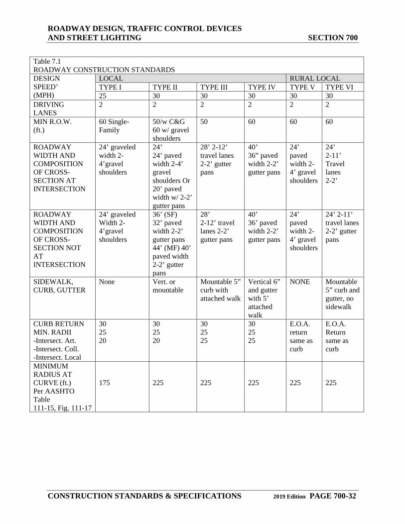
Table 7.1 ROADWAY CONSTRUCTION STANDARDS DESIGN SPEED’ (MPH)
LOCAL RURAL LOCAL TYPE I TYPE II TYPE III TYPE IV TYPE V TYPE VI 25 30 30 30 30 30
DRIVING LANES
2 2 2 2 2 2
MIN R.O.W. (ft.)
60 Single- Family
50/w C&G 60 w/ gravel shoulders
50 60 60 60
ROADWAY WIDTH AND COMPOSITION OF CROSS-SECTION AT INTERSECTION
24’ graveled width 2-4’gravel shoulders
24’ 24’ paved width 2-4’ gravel shoulders Or 20’ paved width w/ 2-2’ gutter pans
28’ 2-12’ travel lanes 2-2’ gutter pans
40’ 36” paved width 2-2’ gutter pans
24’ paved width 2-4’ gravel shoulders
24’ 2-11’ Travel lanes 2-2’
ROADWAY WIDTH AND COMPOSITION OF CROSS-SECTION NOT AT INTERSECTION
24’ graveled Width 2-4’gravel shoulders
36’ (SF) 32’ paved width 2-2’ gutter pans 44’ (MF) 40’ paved width 2-2’ gutter pans
28’ 2-12’ travel lanes 2-2’ gutter pans
40’ 36’ paved width 2-2’ gutter pans
24’ paved width 2-4’ gravel shoulders
24’ 2-11’ travel lanes 2-2’ gutter pans
SIDEWALK, CURB, GUTTER
None Vert. or mountable
Mountable 5” curb with attached walk
Vertical 6” and gutter with 5’ attached walk
NONE Mountable 5” curb and gutter, no sidewalk
CURB RETURN MIN. RADII -Intersect. Art. -Intersect. Coll. -Intersect. Local
30 25 20
30 25 20
30 25 25
30 25 25
E.O.A. return same as curb
E.O.A. Return same as curb
MINIMUM RADIUS AT CURVE (ft.) Per AASHTO Table 111-15, Fig. 111-17
175
225
225
225
225
225
ROADWAY DESIGN, TRAFFIC CONTROL DEVICES AND STREET LIGHTING SECTION 700
CONSTRUCTION STANDARDS & SPECIFICATIONS 2019 Edition PAGE 700-33
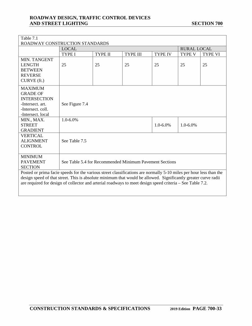
Table 7.1 ROADWAY CONSTRUCTION STANDARDS LOCAL RURAL LOCAL
TYPE I TYPE II TYPE III TYPE IV TYPE V TYPE VI MIN. TANGENT LENGTH BETWEEN REVERSE CURVE (ft.)
25
25
25
25
25
25
MAXIMUM GRADE OF INTERSECTION -Intersect. art. -Intersect. coll. -Intersect. local
See Figure 7.4
MIN., MAX. STREET GRADIENT
1.0-6.0% 1.0-6.0%
1.0-6.0%
VERTICAL ALIGNMENT CONTROL
See Table 7.5
MINIMUM PAVEMENT SECTION
See Table 5.4 for Recommended Minimum Pavement Sections
Posted or prima facie speeds for the various street classifications are normally 5-10 miles per hour less than the design speed of that street. This is absolute minimum that would be allowed. Significantly greater curve radii are required for design of collector and arterial roadways to meet design speed criteria – See Table 7.2.
ROADWAY DESIGN, TRAFFIC CONTROL DEVICES AND STREET LIGHTING SECTION 700
CONSTRUCTION STANDARDS & SPECIFICATIONS 2019 Edition PAGE 700-34
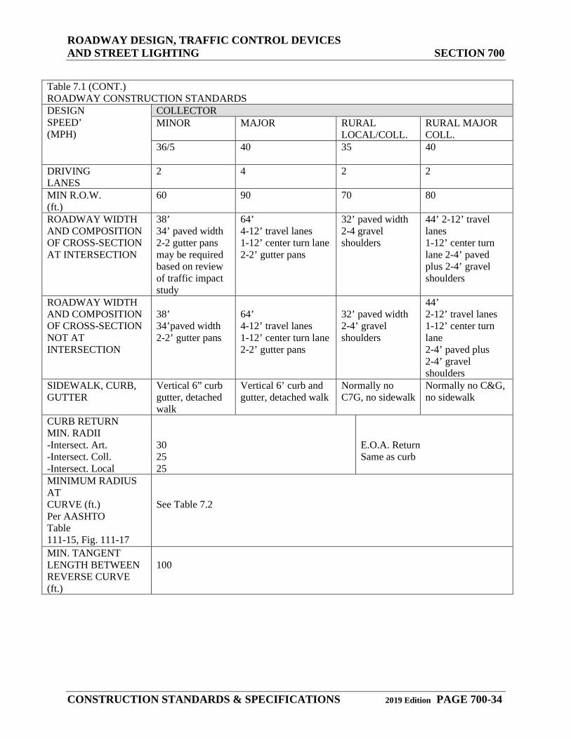
Table 7.1 (CONT.) ROADWAY CONSTRUCTION STANDARDS DESIGN SPEED’ (MPH)
COLLECTOR MINOR MAJOR RURAL
LOCAL/COLL. RURAL MAJOR COLL.
36/5
40 35 40
DRIVING LANES
2 4 2 2
MIN R.O.W. (ft.)
60 90 70 80
ROADWAY WIDTH AND COMPOSITION OF CROSS-SECTION AT INTERSECTION
38’ 34’ paved width 2-2 gutter pans may be required based on review of traffic impact study
64’ 4-12’ travel lanes 1-12’ center turn lane 2-2’ gutter pans
32’ paved width 2-4 gravel shoulders
44’ 2-12’ travel lanes 1-12’ center turn lane 2-4’ paved plus 2-4’ gravel shoulders
ROADWAY WIDTH AND COMPOSITION OF CROSS-SECTION NOT AT INTERSECTION
38’ 34’paved width 2-2’ gutter pans
64’ 4-12’ travel lanes 1-12’ center turn lane 2-2’ gutter pans
32’ paved width 2-4’ gravel shoulders
44’ 2-12’ travel lanes 1-12’ center turn lane 2-4’ paved plus 2-4’ gravel shoulders
SIDEWALK, CURB, GUTTER
Vertical 6” curb gutter, detached walk
Vertical 6’ curb and gutter, detached walk
Normally no C7G, no sidewalk
Normally no C&G, no sidewalk
CURB RETURN MIN. RADII -Intersect. Art. -Intersect. Coll. -Intersect. Local
30 25 25
E.O.A. Return Same as curb
MINIMUM RADIUS AT CURVE (ft.) Per AASHTO Table 111-15, Fig. 111-17
See Table 7.2
MIN. TANGENT LENGTH BETWEEN REVERSE CURVE (ft.)
100
ROADWAY DESIGN, TRAFFIC CONTROL DEVICES AND STREET LIGHTING SECTION 700
CONSTRUCTION STANDARDS & SPECIFICATIONS 2019 Edition PAGE 700-35
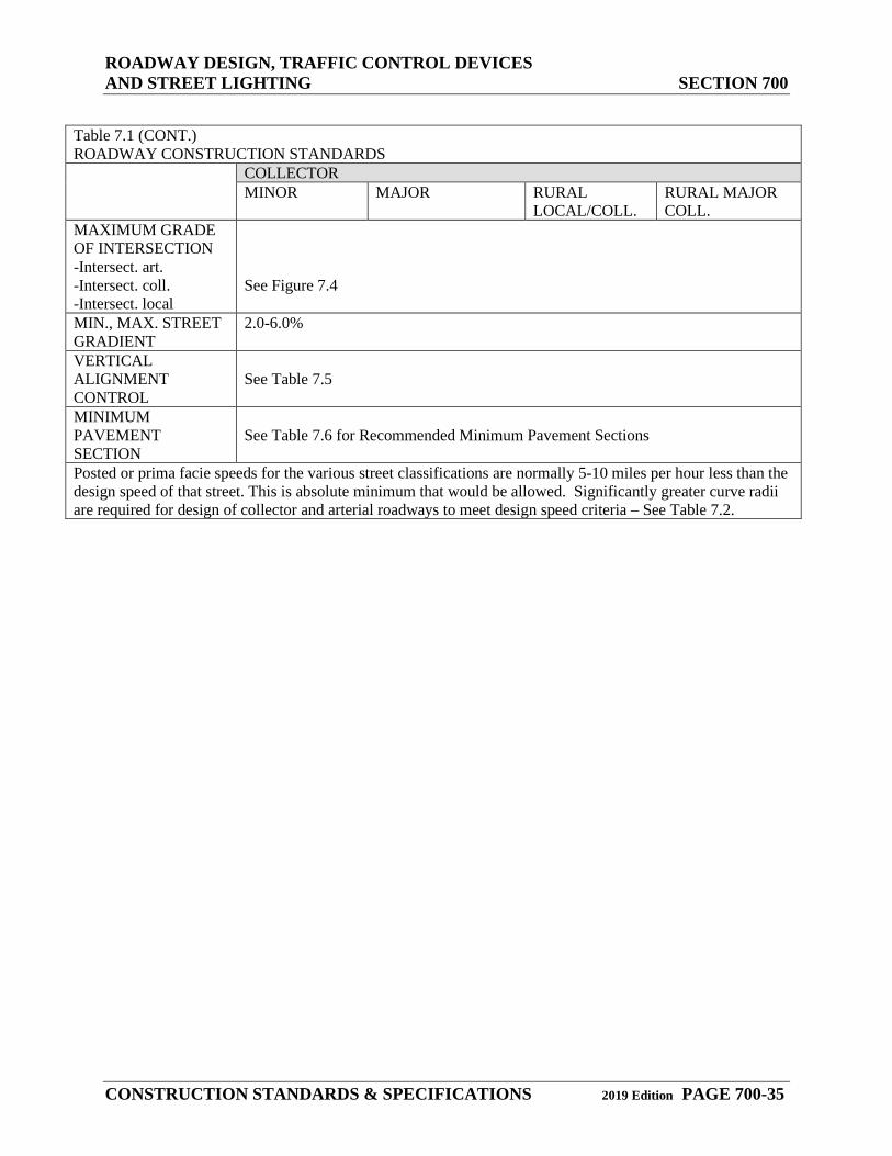
Table 7.1 (CONT.) ROADWAY CONSTRUCTION STANDARDS COLLECTOR
MINOR MAJOR RURAL LOCAL/COLL.
RURAL MAJOR COLL.
MAXIMUM GRADE OF INTERSECTION -Intersect. art. -Intersect. coll. -Intersect. local
See Figure 7.4
MIN., MAX. STREET GRADIENT
2.0-6.0%
VERTICAL ALIGNMENT CONTROL
See Table 7.5
MINIMUM PAVEMENT SECTION
See Table 7.6 for Recommended Minimum Pavement Sections
Posted or prima facie speeds for the various street classifications are normally 5-10 miles per hour less than the design speed of that street. This is absolute minimum that would be allowed. Significantly greater curve radii are required for design of collector and arterial roadways to meet design speed criteria – See Table 7.2.
ROADWAY DESIGN, TRAFFIC CONTROL DEVICES AND STREET LIGHTING SECTION 700
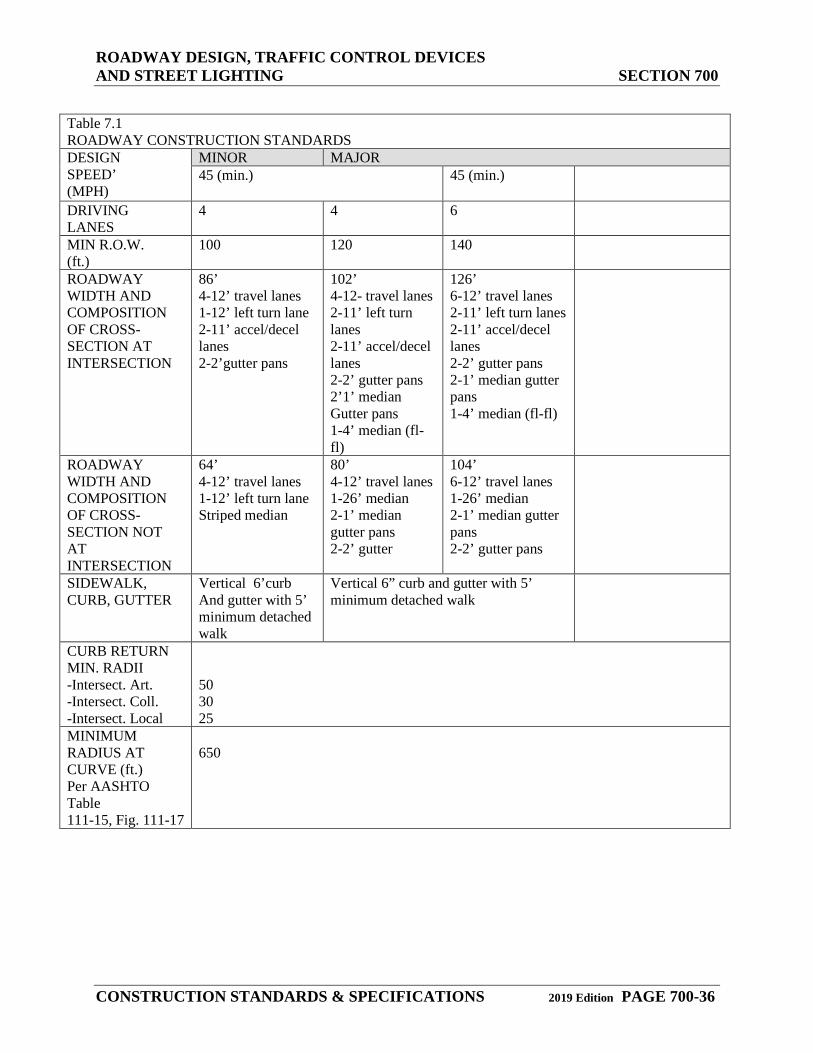
CONSTRUCTION STANDARDS & SPECIFICATIONS 2019 Edition PAGE 700-36
Table 7.1 ROADWAY CONSTRUCTION STANDARDS DESIGN SPEED’ (MPH)
MINOR MAJOR 45 (min.) 45 (min.)
DRIVING LANES
4 4 6
MIN R.O.W. (ft.)
100 120 140
ROADWAY WIDTH AND COMPOSITION OF CROSS-SECTION AT INTERSECTION
86’ 4-12’ travel lanes 1-12’ left turn lane 2-11’ accel/decel lanes 2-2’gutter pans
102’ 4-12- travel lanes 2-11’ left turn lanes 2-11’ accel/decel lanes 2-2’ gutter pans 2’1’ median Gutter pans 1-4’ median (fl-fl)
126’ 6-12’ travel lanes 2-11’ left turn lanes 2-11’ accel/decel lanes 2-2’ gutter pans 2-1’ median gutter pans 1-4’ median (fl-fl)
ROADWAY WIDTH AND COMPOSITION OF CROSS-SECTION NOT AT INTERSECTION
64’ 4-12’ travel lanes 1-12’ left turn lane Striped median
80’ 4-12’ travel lanes 1-26’ median 2-1’ median gutter pans 2-2’ gutter
104’ 6-12’ travel lanes 1-26’ median 2-1’ median gutter pans 2-2’ gutter pans
SIDEWALK, CURB, GUTTER
Vertical 6’curb And gutter with 5’ minimum detached walk
Vertical 6” curb and gutter with 5’ minimum detached walk
CURB RETURN MIN. RADII -Intersect. Art. -Intersect. Coll. -Intersect. Local
50 30 25
MINIMUM RADIUS AT CURVE (ft.) Per AASHTO Table 111-15, Fig. 111-17
650
ROADWAY DESIGN, TRAFFIC CONTROL DEVICES AND STREET LIGHTING SECTION 700
CONSTRUCTION STANDARDS & SPECIFICATIONS 2019 Edition PAGE 700-37
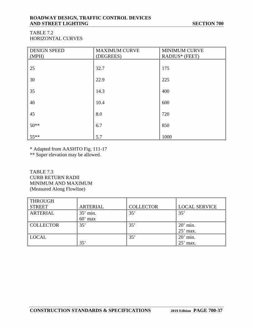
TABLE 7.2 HORIZONTAL CURVES DESIGN SPEED (MPH)
MAXIMUM CURVE (DEGREES)
MINIMUM CURVE RADIUS* (FEET)
25 30 35 40 45 50** 55**
32.7 22.9 14.3 10.4 8.0 6.7 5.7
175 225 400 600 720 850 1000
* Adapted from AASHTO Fig. 111-17 ** Super elevation may be allowed. TABLE 7.3 CURB RETURN RADII MINIMUM AND MAXIMUM (Measured Along Flowline) THROUGH STREET
ARTERIAL
COLLECTOR
LOCAL SERVICE
ARTERIAL 35’ min. 60’ max
35’ 35’
COLLECTOR 35’
35’ 20’ min. 25’ max.
LOCAL 35’
35’ 20’ min. 25’ max.
ROADWAY DESIGN, TRAFFIC CONTROL DEVICES AND STREET LIGHTING SECTION 700
CONSTRUCTION STANDARDS & SPECIFICATIONS 2019 Edition PAGE 700-38
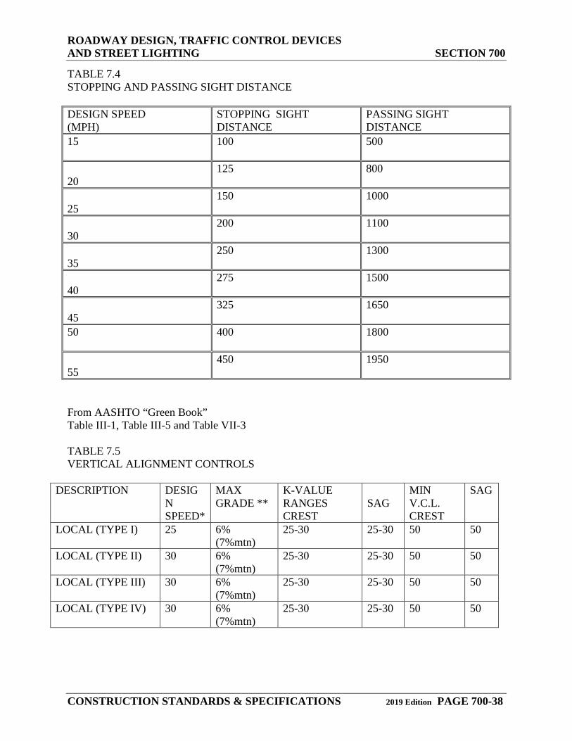
TABLE 7.4 STOPPING AND PASSING SIGHT DISTANCE DESIGN SPEED (MPH)
STOPPING SIGHT DISTANCE
PASSING SIGHT DISTANCE
15
100 500
20
125 800
25
150 1000
30
200 1100
35
250 1300
40
275 1500
45
325 1650
50
400 1800
55
450 1950
From AASHTO “Green Book” Table III-1, Table III-5 and Table VII-3 TABLE 7.5 VERTICAL ALIGNMENT CONTROLS
DESCRIPTION DESIGN SPEED*
MAX GRADE **
K-VALUE RANGES CREST
SAG
MIN V.C.L. CREST
SAG
LOCAL (TYPE I) 25 6% (7%mtn)
25-30 25-30 50 50
LOCAL (TYPE II) 30 6% (7%mtn)
25-30 25-30 50 50
LOCAL (TYPE III) 30 6% (7%mtn)
25-30 25-30 50 50
LOCAL (TYPE IV) 30 6% (7%mtn)
25-30 25-30 50 50
ROADWAY DESIGN, TRAFFIC CONTROL DEVICES AND STREET LIGHTING SECTION 700
CONSTRUCTION STANDARDS & SPECIFICATIONS 2019 Edition PAGE 700-39
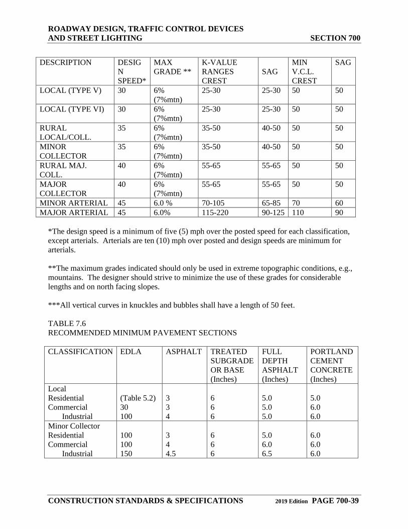
DESCRIPTION DESIG
N SPEED*
MAX GRADE **
K-VALUE RANGES CREST
SAG
MIN V.C.L. CREST
SAG
LOCAL (TYPE V) 30 6% (7%mtn)
25-30 25-30 50 50
LOCAL (TYPE VI) 30 6% (7%mtn)
25-30 25-30 50 50
RURAL LOCAL/COLL.
35 6% (7%mtn)
35-50 40-50 50 50
MINOR COLLECTOR
35 6% (7%mtn)
35-50 40-50 50 50
RURAL MAJ. COLL.
40 6% (7%mtn)
55-65 55-65 50 50
MAJOR COLLECTOR
40 6% (7%mtn)
55-65 55-65 50 50
MINOR ARTERIAL 45 6.0 % 70-105 65-85 70 60 MAJOR ARTERIAL 45 6.0% 115-220 90-125 110 90
*The design speed is a minimum of five (5) mph over the posted speed for each classification, except arterials. Arterials are ten (10) mph over posted and design speeds are minimum for arterials. **The maximum grades indicated should only be used in extreme topographic conditions, e.g., mountains. The designer should strive to minimize the use of these grades for considerable lengths and on north facing slopes. ***All vertical curves in knuckles and bubbles shall have a length of 50 feet. TABLE 7.6 RECOMMENDED MINIMUM PAVEMENT SECTIONS CLASSIFICATION EDLA ASPHALT TREATED
SUBGRADE OR BASE (Inches)
FULL DEPTH ASPHALT (Inches)
PORTLAND CEMENT CONCRETE (Inches)
Local Residential Commercial Industrial
(Table 5.2) 30 100
3 3 4
6 6 6
5.0 5.0 5.0
5.0 6.0 6.0
Minor Collector Residential Commercial Industrial
100 100 150
3 4 4.5
6 6 6
5.0 6.0 6.5
6.0 6.0 6.0
ROADWAY DESIGN, TRAFFIC CONTROL DEVICES AND STREET LIGHTING SECTION 700
CONSTRUCTION STANDARDS & SPECIFICATIONS 2019 Edition PAGE 700-40
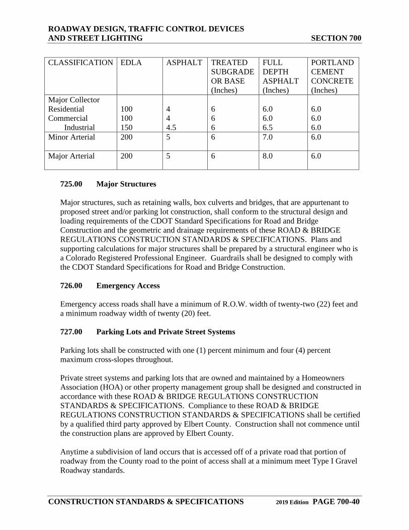
CLASSIFICATION EDLA ASPHALT TREATED
SUBGRADE OR BASE (Inches)
FULL DEPTH ASPHALT (Inches)
PORTLAND CEMENT CONCRETE (Inches)
Major Collector Residential Commercial Industrial
100 100 150
4 4 4.5
6 6 6
6.0 6.0 6.5
6.0 6.0 6.0
Minor Arterial 200 5 6 7.0 6.0
Major Arterial 200 5 6 8.0 6.0
725.00 Major Structures
Major structures, such as retaining walls, box culverts and bridges, that are appurtenant to proposed street and/or parking lot construction, shall conform to the structural design and loading requirements of the CDOT Standard Specifications for Road and Bridge Construction and the geometric and drainage requirements of these ROAD & BRIDGE REGULATIONS CONSTRUCTION STANDARDS & SPECIFICATIONS. Plans and supporting calculations for major structures shall be prepared by a structural engineer who is a Colorado Registered Professional Engineer. Guardrails shall be designed to comply with the CDOT Standard Specifications for Road and Bridge Construction.
726.00 Emergency Access
Emergency access roads shall have a minimum of R.O.W. width of twenty-two (22) feet and a minimum roadway width of twenty (20) feet.
727.00 Parking Lots and Private Street Systems
Parking lots shall be constructed with one (1) percent minimum and four (4) percent maximum cross-slopes throughout.
Private street systems and parking lots that are owned and maintained by a Homeowners Association (HOA) or other property management group shall be designed and constructed in accordance with these ROAD & BRIDGE REGULATIONS CONSTRUCTION STANDARDS & SPECIFICATIONS. Compliance to these ROAD & BRIDGE REGULATIONS CONSTRUCTION STANDARDS & SPECIFICATIONS shall be certified by a qualified third party approved by Elbert County. Construction shall not commence until the construction plans are approved by Elbert County. Anytime a subdivision of land occurs that is accessed off of a private road that portion of roadway from the County road to the point of access shall at a minimum meet Type I Gravel Roadway standards.
ROADWAY DESIGN, TRAFFIC CONTROL DEVICES AND STREET LIGHTING SECTION 700
CONSTRUCTION STANDARDS & SPECIFICATIONS 2019 Edition PAGE 700-41
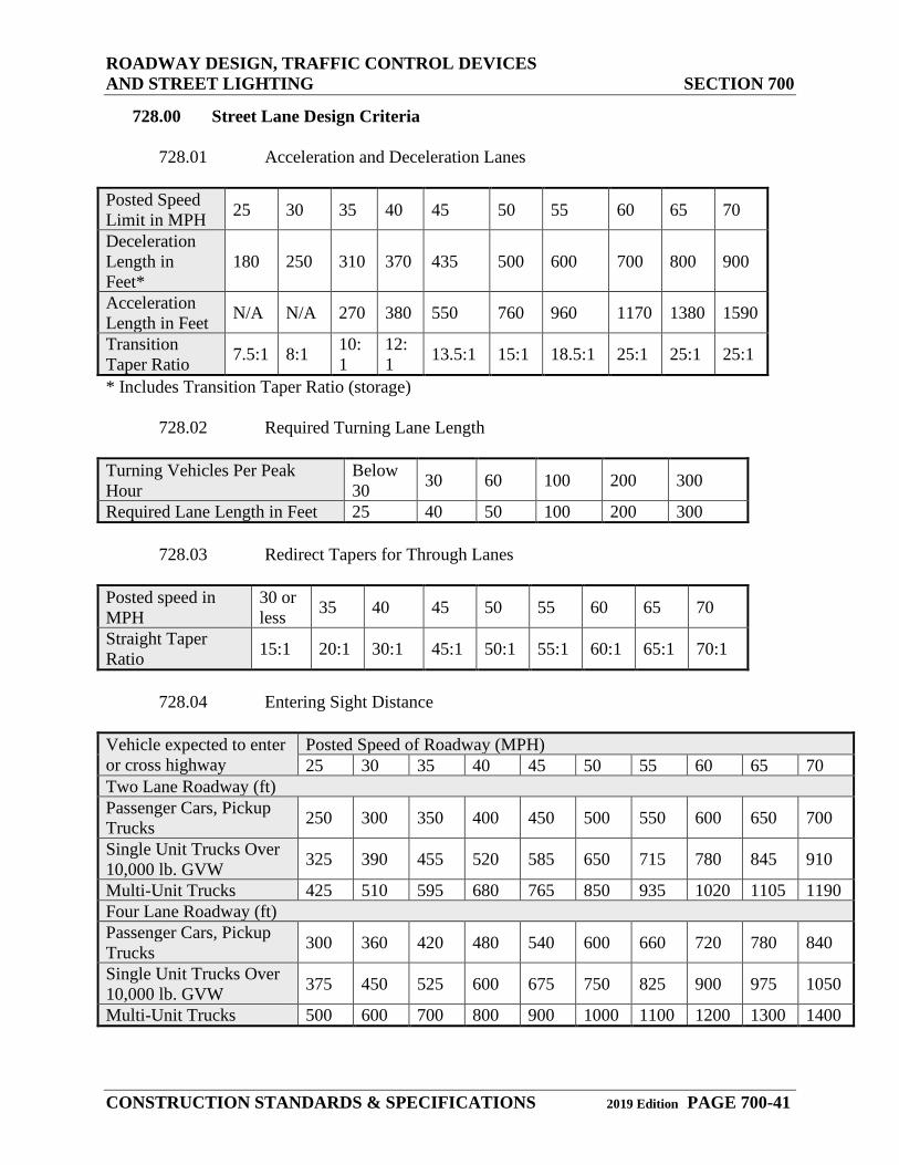
728.00 Street Lane Design Criteria
728.01 Acceleration and Deceleration Lanes Posted Speed Limit in MPH 25 30 35 40 45 50 55 60 65 70
Deceleration Length in Feet*
180 250 310 370 435 500 600 700 800 900
Acceleration Length in Feet N/A N/A 270 380 550 760 960 1170 1380 1590
Transition Taper Ratio 7.5:1 8:1 10:
1 12:1 13.5:1 15:1 18.5:1 25:1 25:1 25:1
* Includes Transition Taper Ratio (storage)
728.02 Required Turning Lane Length Turning Vehicles Per Peak Hour
Below 30 30 60 100 200 300
Required Lane Length in Feet 25 40 50 100 200 300
728.03 Redirect Tapers for Through Lanes Posted speed in MPH
30 or less 35 40 45 50 55 60 65 70
Straight Taper Ratio 15:1 20:1 30:1 45:1 50:1 55:1 60:1 65:1 70:1
728.04 Entering Sight Distance
Vehicle expected to enter or cross highway
Posted Speed of Roadway (MPH) 25 30 35 40 45 50 55 60 65 70
Two Lane Roadway (ft) Passenger Cars, Pickup Trucks 250 300 350 400 450 500 550 600 650 700
Single Unit Trucks Over 10,000 lb. GVW 325 390 455 520 585 650 715 780 845 910
Multi-Unit Trucks 425 510 595 680 765 850 935 1020 1105 1190 Four Lane Roadway (ft) Passenger Cars, Pickup Trucks 300 360 420 480 540 600 660 720 780 840
Single Unit Trucks Over 10,000 lb. GVW 375 450 525 600 675 750 825 900 975 1050
Multi-Unit Trucks 500 600 700 800 900 1000 1100 1200 1300 1400
ROADWAY DESIGN, TRAFFIC CONTROL DEVICES AND STREET LIGHTING SECTION 700
CONSTRUCTION STANDARDS & SPECIFICATIONS 2019 Edition PAGE 700-42
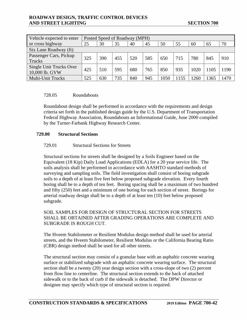
Vehicle expected to enter or cross highway
Posted Speed of Roadway (MPH) 25 30 35 40 45 50 55 60 65 70
Six Lane Roadway (ft) Passenger Cars, Pickup Trucks 325 390 455 520 585 650 715 780 845 910
Single Unit Trucks Over 10,000 lb. GVW 425 510 595 680 765 850 935 1020 1105 1190
Multi-Unit Trucks 525 630 735 840 945 1050 1155 1260 1365 1470
728.05 Roundabouts
Roundabout design shall be performed in accordance with the requirements and design criteria set forth in the published design guide by the U.S. Department of Transportation Federal Highway Association, Roundabouts an Informational Guide, June 2000 compiled by the Turner-Farbank Highway Research Center.
729.00 Structural Sections
729.01 Structural Sections for Streets
Structural sections for streets shall be designed by a Soils Engineer based on the Equivalent (18 Kip) Daily Load Applications (EDLA) for a 20 year service life. The soils analysis shall be performed in accordance with AASHTO standard methods of surveying and sampling soils. The field investigation shall consist of boring subgrade soils to a depth of at least five feet below proposed subgrade elevation. Every fourth boring shall be to a depth of ten feet. Boring spacing shall be a maximum of two hundred and fifty (250) feet and a minimum of one boring for each section of street. Borings for arterial roadway design shall be to a depth of at least ten (10) feet below proposed subgrade.
SOIL SAMPLES FOR DESIGN OF STRUCTURAL SECTION FOR STREETS SHALL BE OBTAINED AFTER GRADING OPERATIONS ARE COMPLETE AND SUBGRADE IS ROUGH CUT.
The Hveem Stabilometer or Resilient Modulus design method shall be used for arterial streets, and the Hveem Stabilometer, Resilient Modulus or the California Bearing Ratio (CBR) design method shall be used for all other streets.
The structural section may consist of a granular base with an asphaltic concrete wearing surface or stabilized subgrade with an asphaltic concrete wearing surface. The structural section shall be a twenty (20) year design section with a cross-slope of two (2) percent from flow line to centerline. The structural section extends to the back of attached sidewalk or to the back of curb if the sidewalk is detached. The DPW Director or designee may specify which type of structural section is required.
ROADWAY DESIGN, TRAFFIC CONTROL DEVICES AND STREET LIGHTING SECTION 700
CONSTRUCTION STANDARDS & SPECIFICATIONS 2019 Edition PAGE 700-43
The following standards shall be used in the design of pavement sections for public and private roadways in Elbert County. These minimum pavement thicknesses may be used for preliminary planning purposes only. Final pavement designs shall be based on actual subgrade support test results. Structural credit for lime stabilized subgrade may be allowed at the discretion of the DPW Director or designee if field verification and testing documents are provided. The DPW Director or designee may require additional subgrade testing to confirm whether the pavement design thickness is satisfactory.
The following structural strength coefficients should be the maximum used for pavement design:
Asphalt………………………………………………………. 0.40 CDOT Class 6 Base Course…………………………………. 0.12 Other Base Material with R value ≥ 75……………………… 0.12
At the discretion of the DPW Director or designee, a maximum coefficient of up to 0.12 may be used for stabilized subgrade. Portland cement concrete pavement designs may be allowed with the DPW Director or designee approval.
729.02 Structural Sections for Parking Lots
Structural sections for parking lots shall be designed by a Soils Engineer based on a soil’s analysis in accordance with AASHTO T-86 standard methods of surveying and sampling soils. The Hveem Stabilometer, Resilient Modulus or the California Bearing Ratio (CBR) design method shall be used for parking lots. The structural section may consist of a granular base with an asphaltic concrete wearing surface, a full-depth asphalt section, or stabilized subgrade with an asphaltic concrete wearing surface. Based on the structural sections and the typical daily traffic volumes (shown in the Street Design Criteria table), the DPW Director or designee shall determine into which category a parking lot is placed and consequently which of these CONSTRUCTION STANDARDS & SPECIFICATIONS shall apply.
729.03 Structural Sections for Reconstruction of Existing Low Volume Roadways
Periodically, it is necessary to completely reconstruct existing roadways. It is Elbert County’s desire to accomplish reconstruction in a manner that results in a roadway surface that satisfies a 20-year pavement life in a cost-effective manner with minimal inconvenience to surrounding residences, businesses or other potential users. Such reconstruction programs shall have minimal impact to existing facilities, utilities, subgrades, or otherwise usable structures/improvements. Additionally, all design and construction techniques and procedures shall be performed in a manner that balances overall cost with impact and inconvenience to Elbert County residents. The following are guidelines that shall be considered in the design. Consultants, designers, and Contractors shall also consider other feasible options to achieve practical roadway reconstruction that is acceptable to Elbert County and the affected public.
ROADWAY DESIGN, TRAFFIC CONTROL DEVICES AND STREET LIGHTING SECTION 700
CONSTRUCTION STANDARDS & SPECIFICATIONS 2019 Edition PAGE 700-44
The geotechnical report shall address the following items:
Why the roadway is to be reconstructed Why failure is taking place and what type(s) of failure: Drainage Saturated sub-grade Heaving Oxidation Age of roadway and number of overlays placed Existing subsurface problems Drainage issues
729.03.01 Site Exploration
The DPW Director or designees shall identify the limits of proposed reconstruction for the roadway surfaces, concrete curbs and gutters, crosspans, etc. The Project Geotechnical Engineer shall perform site exploration(s) as follows:
Borings shall be conducted at a frequency of at least one (1) per five hundred (500) linear feet of roadway per lane or as necessary to achieve proper design recommendations or a minimum of two (2) per street segment or where obvious surface problems/failures features exist. Borings shall extend to a minimum of five (5) feet below existing grade or to a depth of the proposed utility, unless utility conflicts are prohibitive. Every fourth boring shall be advanced to a minimum of ten (10) feet below the existing grade. Sufficient sampling, including relatively undisturbed sampling, shall be performed at depths just below the surface to two (2) feet below the surface to address the stability of the existing subgrade soils. A minimum of one (1) undisturbed sample per soil type per roadway shall be obtained within this shallow zone. Additional samples shall be obtained to evaluate the characteristics of the subsurface soils with respect to soil classification, in-situ moisture content, swell / settlement potential, subgrade support, and stability within the five (5) foot layer under the pavement. Observations shall be made of the existing grades, drainages, landscaping, nearby water features, and other factors that may influence moisture infiltration into the pavement subgrade.
729.03.02 Pavement Reconstruction Design and Reports
The pavement design shall be based on information obtained from subsurface soil characteristics and site observations during the site exploration program and from expected traffic loading. The pavement design shall also consider the impact to the public, as well as relative cost of reconstruction. The following guidelines shall be adhered to in the design of pavement section(s) and subgrade preparation:
ROADWAY DESIGN, TRAFFIC CONTROL DEVICES AND STREET LIGHTING SECTION 700
CONSTRUCTION STANDARDS & SPECIFICATIONS 2019 Edition PAGE 700-45
The default subgrade preparation for reconstructed Low Volume Pavements (EDLA < 40) shall consist of either removing the existing asphalt surface and paving the designed pavement layer over the existing subgrade OR recycling the existing asphalt surface into the underlying subgrade to a depth of at least twelve (12) inches using an in-place recycling machine, blading to the design grades, compacting to the recommended density (as determined by either AASHTO T99 or T180, depending upon subgrade classification) and paving. The Pavement Design Report shall address the feasibility of utilizing one of the above procedures for the subgrade preparation. For subgrades with near-optimum moisture likely to exhibit minor stability problems, the asphalt shall be rotomilled into the underlying subgrade to a depth of at least twelve (12) inches, bladed to the design elevation and stabilized with twelve (12) percent Type C Fly-Ash to a depth of at least twelve (12) inches. A maximum structural coefficient of 0.10 may be used for this twelve (12) inch layer. This shall be reduced to as low as 0.06 for subgrades with clay content exceeding fifty (50) percent, based upon the Project Geotechnical Engineer’s recommendation. If it is determined that the subgrade preparations detailed within this section may result in a poor paving platform or pose a long-term concern with respect to heave or settlement, then alternative recommendations shall be provided by the Project Geotechnical Engineer and approved by the DPW Director or designee Such alternates shall consider cost, time, and performance and may include limited over-excavation, moisture treatment, chemical and/or aggregate stabilization, edge drains, and/or increased pavement thickness.
729.04 Edge Drains
Edge drains shall be required along public roadways at the discretion of the DPW Director or designee. Edge drains shall be located in order to intercept water infiltration from landscaping and storm runoff.
Edge drains shall be installed in the following locations:
Along landscaped medians; Where final roadway pavement slope is less than one and one-half (1.5) percent; Along the “uphill” roadway edge where the roadway is located on a cut slope and the roadway pavement slope is less than two (2) percent; Along both roadway edges where the roadway is located at the bottom of a “valley”, with the toe of slopes on both sides of the roadway; Along roadways that may have poor drainage due to unusual circumstances
Edge drains are not required in areas where final grade slopes away from a paved surface at a minimum slope of two (2) percent.
All edge drains should be placed behind the curb and at a depth specified on the approved plans and backfilled with free draining three-quarters (¾) inch washed gravel protected by geotextile fabric.
ROADWAY DESIGN, TRAFFIC CONTROL DEVICES AND STREET LIGHTING SECTION 700
CONSTRUCTION STANDARDS & SPECIFICATIONS 2019 Edition PAGE 700-46
730.00 SIGNAGE AND PAVEMENT MARKINGS
731.00 Signs
731.01 Street Name Signs
Street name signs shall be furnished and installed by the Contractor or Developer and may be inspected by Elbert County before and after installation. Street name signs shall have white letters on a green background, and shall comply with the following:
All signs shall be constructed with 0.080 aluminum blanks. They shall have three-eighths (⅜) inch holes punched in the center two (2) inches from the bottom and top edges, green high intensity, retro-reflective sheeting, high intensity retro-reflective letters or numbers. The street name blank shall be nine (9) inches in height, with six (6) inch Series C upper case letters or numbers and three (3) inch FHWA Series C upper case prefix or suffix. Plate must be dog bone style. No border, logo, or county designator shall be included with the sign The length of the sign shall vary due to the length of the street name. FHWA Series B letters may be permitted to maintain the length of the street name sign. Silk-screened signs are acceptable if they are manufactured with high intensity, retro-reflective sheeting and 3M “Scotchlite” Brand Process Colors transparent inks or equivalent. Signs fabricated with high intensity sheeting with translucent 3M “EC” film or equivalent are also allowed. At every cross intersection, two (2) street name signs shall be provided for each named street. At every tee intersection, one (1) street name sign shall be provided for each named street. Signs manufactured with sheeting and letters placed back to back on the same sign blank are not permitted.
Prior to installing custom signs and/or posts in a development, the Developer or Contractor shall obtain a signed maintenance agreement with the DPW Director or designee.
731.02 Illuminated Signs
Signalized intersections shall have eight (8) foot internally illuminated street name signs which shall be furnished and installed by the Contractor or Developer and shall be inspected by Elbert County. Signs shall be supplied by a manufacturing company approved by the County Engineer. Signs shall be provided for installation on each traffic signal mast arm at each intersection. All sign lettering shall be uppercase. Sign lettering shall be ten (10) inches in height, FHWA Series C letters. The use of FHWA Series B letters may be allowed when space requirements are limited. Suffixes shall be five (5) inches in height. Lettering shall be at least four (4) inches in height where a two-line
ROADWAY DESIGN, TRAFFIC CONTROL DEVICES AND STREET LIGHTING SECTION 700
CONSTRUCTION STANDARDS & SPECIFICATIONS 2019 Edition PAGE 700-47
application is desired or three (3) inches in height where a three-line application is desired.
Borders. Signs shall not include a border, logo, or county designator. Spacing. The spacing to the top and bottom borders should be equal. The lateral spacing to the vertical borders should also be equal. Spacing used in words, words and arrow, a letter and arrow, or a word and numeral in a line copy should be approximately one (1) to one and one-half (1½) times the uppercase letter height used in that line of copy. Excessively long street names may be allowed to have modified kern or letter widths but shall maintain the ten (10) inch required letter height. Arrows. Arrows shall comply with the MUTCD Standard Highway Sign Handbook. A twelve (12) inch Elbert County logo shall be placed on the left face side of the sign and centered accordingly. Color. Letters and numbers shall be white with a green background face. The sign panel shall consist of placing White 3M “3990t” translucent, high intensity, retro-reflective sheeting under green 3M “1175c” EC Film. The colors shall not fade when exposed to an accelerated test of ultraviolet light equivalent to five years of outdoor exposure. Mechanical Specifications. The outer dimensions of the sign assembly shall be standard nominal heights of 22, or 24, inches, and standard nominal width of 8 feet. The maximum thickness of the sign shall be 1.60 inches. The maximum weight shall not exceed 75 lbs. The long edges of the sign shall be made from a single section of 6000 series aluminum extrusion. The ends caps shall be affixed to the frame with stainless steel screws. The power supply shall be mounted internally in one of the end caps. The non-electrical end cap shall be removable to enable replacing panels and components. The sign shall have a front panel that is UV, weather, abrasion and impact resistant. The front panel shall be replaceable so that maintaining agencies have the option to supply their own sheeting and electrocut film for the sign faces. Mounting System. Signs must be supplied with underhang mounting brackets on two positions on the top of the sign. Mounting bracket shall pivot to allow the sign to swing freely. Bracket shall have a bolt hole pattern to accept Pelco SE-5015, SE-5146, or equivalent. Environmental Specifications. The sign shall be designed and constructed to withstand 178 Km/h (110 mph) wind loads in conformance with the requirements of the AASHTO publication, "Standard Specifications for Structural Supports of Highway Signs, Luminaries and Traffic Signals", 4th Edition 2001. The sign and power supply should be able to withstand and operate at temperature extremes of -22 deg F to +140 deg F. Signs shall be tested and certified for the following environmental conditions: Exclusion of Water Test, Strain Relief Test, Temperature Test and Dielectric Voltage-Withstand Test A representative sample of the product shall be tested in accordance with the Standards for Electric Signs (UL 48). Luminance. The entire surface of the sign panel must be evenly illuminated with a minimum average brightness reading at the letters of 300 lux and a variation of no more than 40% for any reading from the average (minimum of 10 readings). Each background reading measured must not vary by more than 40% (minimum of 10 readings) from the average of the background brightness readings. The light transmission factor of the sign panel must provide a letter to background ratio of a minimum of 4:1.
ROADWAY DESIGN, TRAFFIC CONTROL DEVICES AND STREET LIGHTING SECTION 700
CONSTRUCTION STANDARDS & SPECIFICATIONS 2019 Edition PAGE 700-48
Light Source. The light source for the sign shall be LEDs (light emitting diodes). mounted along the edges of the sign. The LEDs shall evenly illuminate a light panel that is the same dimensions of the sign face. The LEDs shall have a minimum projected life of 50,000 hours. A maximum of four LEDs per square foot shall be used. Energy Requirements. The overall power required shall not exceed 4 Watts per square foot. Energy Star Partner. The sign shall be an Energy Star Qualified Product. Quality Assurance. Manufacturer must be ISO 9001:2000 certified. Electrical Standards. Sign shall be listed and approved to UL 48 Standards. The outside of the sign shall be marked with the authorized listing agency mark. Product Guarantee. Sign must be guaranteed for a minimum of three years. Final Layout. Final layout and lettering details shall be submitted to Elbert County prior to fabrication.
731.03 Stop Signs
Stop signs shall be installed at all approaches to streets designated by Elbert County as through streets. Stop signs shall be mounted on the same support posts as street name signs where possible. All signs shall have Diamond Grade Reflective sheeting and meet the MUTCD Conventional Road Dimension charts and the MUTCD Standard Highway Signs.
731.04 Other Signs
Regulatory, warning, guide, informational, and custom signs shall be installed at locations designated by the DPW Director or designee. All signs shall have Diamond Grade Reflective sheeting and shall meet the MUTCD Conventional Road Dimension charts and the MUTCD Standard Highway Signs. School and pedestrian warning signs shall be fluorescent yellow/green with diamond grade, retro-reflective sheeting.
731.05 ‘No Parking’ Signs
‘No Parking’ signs shall have high Diamond Grade Reflective sheeting. Both the sign post and the support post shall be of the square telescoping type, twelve (12) gauge. Holes shall be punched on all four (4) sides and along the entire length of the post. The sign post shall be two (2) inches square by ten (10) feet, and the support post shall be two and one-quarter (2¼) inches square by three (3) feet.
731.06 Sign Dimensions
The signs shall be fabricated in accordance with the dimensions described on the MUTCD Conventional Road Dimension charts and the MUTCD Standard Highway Signs.

ROADWAY DESIGN, TRAFFIC CONTROL DEVICES AND STREET LIGHTING SECTION 700
CONSTRUCTION STANDARDS & SPECIFICATIONS 2019 Edition PAGE 700-49
731.07 Sign Installation
Install per the MUTCD guidelines and the CDOT Standard Specifications for Road and Bridge Construction.
732.00 Sign Posts and Support Posts
All sign supports and sign posts shall conform to specifications for perforated square steel tubing and to ASTM A366, Standard Specifications for Cold Rolled Carbon Steel Sheets, Commercial Quality. Tubing with plain finish shall be roll-formed from 10-gauge (.135 U.S.S. Gauge) and 12-gauge (.105 U.S.S Gauge) hot rolled steel, ASTM A1011 Grade 50 pickled and oiled. Tubing with galvanized finish shall be roll-formed from 10-gauge (.135 U.S.S. Gauge) and 12-gauge (.105 U.S.S. Gauge) hot rolled steel, galvanized material ASTM A653 Grade 50. The average minimum yield strength after cold forming shall be 60,000 PSI. Posts shall conform to the following sign dimensions:
The finished members shall be straight and shall have a smooth, uniform finish. Consecutive sizes of tubes shall freely telescope with a minimum amount of play. All holes and cut-off ends shall be free of burrs. Seven-sixteenth (3/8) inch diameter holes shall be punched on one (1) inch centers on the entire length of all sides of the tube. All posts shall be galvanized.
733.00 Pavement Markings
The Contractor shall submit a Pavement Marking Plan to the County Engineer for approval prior to beginning work. The Pavement Marking Plan shall meet the requirements outlined in the MUTCD. Markings shall consist of extrusion applied, preformed plastic, or thermoplastic material conforming to Sections 713.12 and 713.14 of the CDOT Standard Specifications for Road and Bridge Construction. The Contractor is solely responsible for placement and maintenance of all necessary temporary and permanent pavement markings until Construction Acceptance is issued.
All temporary pavement markings shall comply with Section 627 of the CDOT Standard Specifications for Road and Bridge Construction.
All permanent pavement markings shall be thermoplastic. No Low VOC Solvent Paint or Epoxy shall be installed in Elbert County R.O.W or easements. Waterborne Paint or plastic preformed materials may be allowed at the discretion of the County Engineer.
Total Sign Area Sign Post Dimensions Support Post Dimensions Less than 2 sq. ft. 2” x 2” x 10’ 2 ¼” x 3’ 2 to 9 sq. ft. 2” x 2” x 12’ 2 ¼” x 3’ Over 9 sq. ft. 2” x 2” x 12’ 2 ¼” x 3’
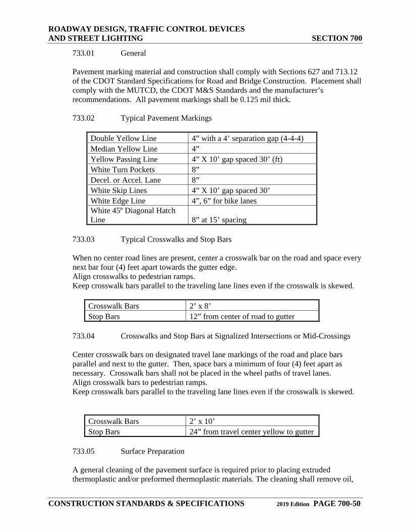
ROADWAY DESIGN, TRAFFIC CONTROL DEVICES AND STREET LIGHTING SECTION 700
CONSTRUCTION STANDARDS & SPECIFICATIONS 2019 Edition PAGE 700-50
733.01 General
Pavement marking material and construction shall comply with Sections 627 and 713.12 of the CDOT Standard Specifications for Road and Bridge Construction. Placement shall comply with the MUTCD, the CDOT M&S Standards and the manufacturer’s recommendations. All pavement markings shall be 0.125 mil thick.
733.02 Typical Pavement Markings
Double Yellow Line 4” with a 4’ separation gap (4-4-4) Median Yellow Line 4” Yellow Passing Line 4” X 10’ gap spaced 30’ (ft) White Turn Pockets 8” Decel. or Accel. Lane 8” White Skip Lines 4” X 10’ gap spaced 30’ White Edge Line 4”, 6” for bike lanes White 45º Diagonal Hatch Line 8” at 15’ spacing
733.03 Typical Crosswalks and Stop Bars
When no center road lines are present, center a crosswalk bar on the road and space every next bar four (4) feet apart towards the gutter edge. Align crosswalks to pedestrian ramps. Keep crosswalk bars parallel to the traveling lane lines even if the crosswalk is skewed.
Crosswalk Bars 2’ x 8’ Stop Bars 12” from center of road to gutter
733.04 Crosswalks and Stop Bars at Signalized Intersections or Mid-Crossings
Center crosswalk bars on designated travel lane markings of the road and place bars parallel and next to the gutter. Then, space bars a minimum of four (4) feet apart as necessary. Crosswalk bars shall not be placed in the wheel paths of travel lanes. Align crosswalk bars to pedestrian ramps. Keep crosswalk bars parallel to the traveling lane lines even if the crosswalk is skewed.
Crosswalk Bars 2’ x 10’ Stop Bars 24” from travel center yellow to gutter
733.05 Surface Preparation
A general cleaning of the pavement surface is required prior to placing extruded thermoplastic and/or preformed thermoplastic materials. The cleaning shall remove oil,
ROADWAY DESIGN, TRAFFIC CONTROL DEVICES AND STREET LIGHTING SECTION 700
CONSTRUCTION STANDARDS & SPECIFICATIONS 2019 Edition PAGE 700-51
dirt, dust, grease, and other foreign materials. It is recommended that new thermoplastic pavement markings be applied immediately after new asphalt has been placed, thereby reducing the necessary surface preparation and allowing the asphalt rollers to inlay preformed pavement marking material. If the roadway striping cannot be placed immediately following paving operations, then it is the sole responsibility of the Contractor to apply and maintain temporary pavement markings to sufficiently delineate travel lanes until permanent pavement markings can be placed. Pavement markings shall be placed within two (2) weeks of completion of paving operations.
733.06 Prior to Placement of Pavement Marking Materials Control Points. Set control points to ensure compliance with the approved Pavement Marking Plan. Conflicts. Verify that there are no conflicts between the approved Pavement Marking Plan and existing pavement markings. Material. Verify the pavement marking materials to be installed.
Surface Preparation. Ensure the surface is cleaned and free of moisture, oil, dirt, dust, grease, and other foreign materials. Verify whether sandblasting or primer is required. Temperature. Check that air temperature complies with the manufacturer’s recommendations. Signing Conflicts. Check for conflicts with signage.
733.07 Placement of Pavement Markings
During the placement of pavement markings, regular checks shall be performed to ensure that the surface is clean and dry. The Contractor shall regularly check pavement markings for good workmanship and straightness. When placing pavement markings, the following requirements apply:
Application Procedures. Application procedures shall comply with the manufacturer's recommendations and these CONSTRUCTION STANDARDS & SPECIFICATIONS. Application Rate. Application rate of pavement marking materials shall comply with these CONSTRUCTION STANDARDS & SPECIFICATIONS. Reflective Beads. Check that the application rate of reflective beads complies with specified requirements. Protection. Traffic cones shall be used to prevent damage to new pavement markings. Permanent Markings. Verify proper application of all permanent markings. Conflicting Pavement Markings. Pavement markings shall not be conflicting or confusing. Extruded Thermoplastic Pavement Markings. Ensure that extrusion equipment provides proper heating, mixing, and flow of material. Preformed Thermoplastic Pavement Markings. For the application of preformed pavement markings, consider the following: Heating. Ensure that equipment provides proper heating and placement of material. Existing Pavement. When placed on existing cold pavement, check for a clean, dry, and properly prepared surface. Verify if sandblasting is required. Ensure that primer, if required, has been properly applied. Check for appropriate splicing sequence.
ROADWAY DESIGN, TRAFFIC CONTROL DEVICES AND STREET LIGHTING SECTION 700
CONSTRUCTION STANDARDS & SPECIFICATIONS 2019 Edition PAGE 700-52
Inlay. For hot bituminous inlay placement, ensure that the material is applied in the proper location and sequence on the new mat. Check that the pavement surface is at the recommended temperature to obtain proper inlay.
740.00 TRAFFIC SIGNALS
741.00 Control of Work
741.01 Regulations and Code
All electrical equipment shall comply with the CDOT Standard Specifications for Road and Bridge Construction. In addition to the requirements of the approved plans, all material and work shall comply with the National Electrical Code (NEC) and these CONSTRUCTION STANDARDS & SPECIFICATIONS.
741.02 Inspection
All material delivered to the site shall be subject to inspection—prior to or during installation—as deemed necessary by the Elbert County Inspector/Representative. The Elbert County Inspector/Representative may request samples of certain materials from the factory or warehouse for testing purposes prior to delivery on the site. Material which has been rejected by Elbert County shall not be delivered to the work site, and any material rejected at the work site shall be immediately removed from the site. Failure by Elbert County to note faulty material or workmanship during progress of the work shall not relieve the Contractor of the responsibility of removing and/or replacing faulty materials at the Contractor’s expense during the warranty period.
Any work within the public R.O.W. shall require two working days [forty-eight (48) hours] prior notice to Elbert County by the Contractor or Developer.
New Traffic Signal or Design Modification, Pre-acceptance Inspection Checklist
The following checklist is a guideline offered to electrical contractors building traffic signals within Elbert County. It is recommended contractors review checklist prior to and during construction to facilitate the final inspection processes. This is offered as a guideline only and may or may not include all Elbert County requirements. It remains the contractor’s responsibility to review all applicable documents to ensure compliance with Elbert County CONSTRUCTION STANDARS & SPECIFICATIONS. Elbert County encourages contractor input. Please submit requests or comments to the Elbert County Road & Bridge Superintendent/Elbert County Engineer.:
New Traffic Signal or Design Modification
Pre-acceptance Inspection Checklist Intersection:
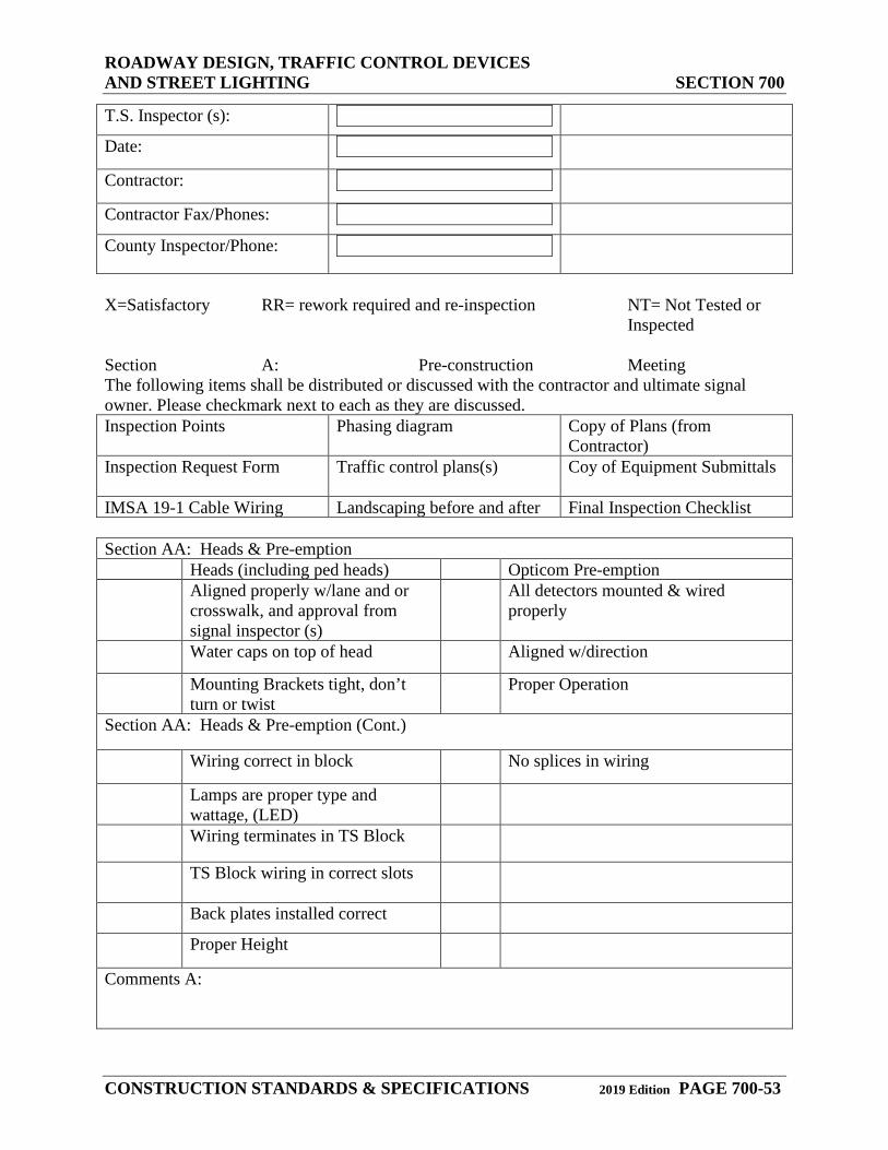
ROADWAY DESIGN, TRAFFIC CONTROL DEVICES AND STREET LIGHTING SECTION 700
CONSTRUCTION STANDARDS & SPECIFICATIONS 2019 Edition PAGE 700-53
T.S. Inspector (s):
Date:
Contractor:
Contractor Fax/Phones:
County Inspector/Phone:
X=Satisfactory RR= rework required and re-inspection NT= Not Tested or Inspected Section A: Pre-construction Meeting The following items shall be distributed or discussed with the contractor and ultimate signal owner. Please checkmark next to each as they are discussed. Inspection Points Phasing diagram Copy of Plans (from
Contractor) Inspection Request Form Traffic control plans(s) Coy of Equipment Submittals
IMSA 19-1 Cable Wiring Landscaping before and after Final Inspection Checklist Section AA: Heads & Pre-emption Heads (including ped heads) Opticom Pre-emption
Aligned properly w/lane and or crosswalk, and approval from signal inspector (s)
All detectors mounted & wired properly
Water caps on top of head
Aligned w/direction
Mounting Brackets tight, don’t turn or twist
Proper Operation
Section AA: Heads & Pre-emption (Cont.)
Wiring correct in block
No splices in wiring
Lamps are proper type and wattage, (LED)
Wiring terminates in TS Block
TS Block wiring in correct slots
Back plates installed correct
Proper Height
Comments A:
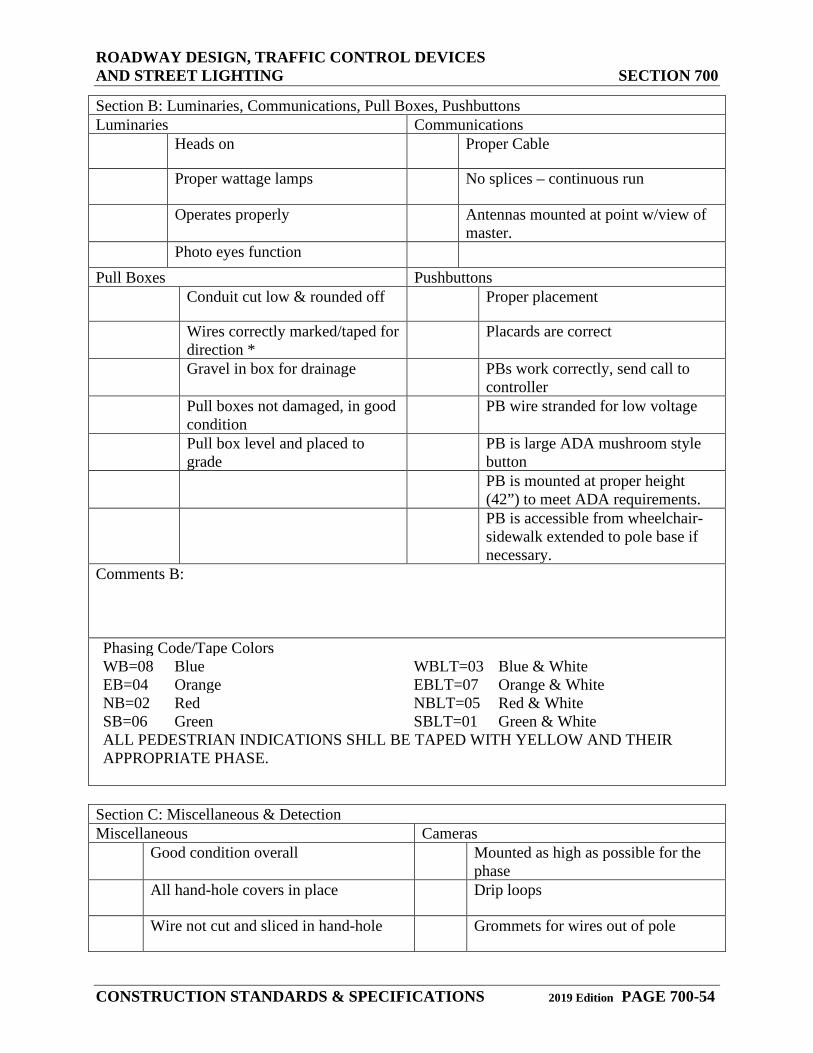
ROADWAY DESIGN, TRAFFIC CONTROL DEVICES AND STREET LIGHTING SECTION 700
CONSTRUCTION STANDARDS & SPECIFICATIONS 2019 Edition PAGE 700-54
Section B: Luminaries, Communications, Pull Boxes, Pushbuttons Luminaries Communications
Heads on
Proper Cable
Proper wattage lamps
No splices – continuous run
Operates properly
Antennas mounted at point w/view of master.
Photo eyes function
Pull Boxes Pushbuttons
Conduit cut low & rounded off
Proper placement
Wires correctly marked/taped for direction *
Placards are correct
Gravel in box for drainage
PBs work correctly, send call to controller
Pull boxes not damaged, in good condition
PB wire stranded for low voltage
Pull box level and placed to grade
PB is large ADA mushroom style button
PB is mounted at proper height (42”) to meet ADA requirements.
PB is accessible from wheelchair- sidewalk extended to pole base if necessary.
Comments B: Phasing Code/Tape Colors WB=08 Blue WBLT=03 Blue & White EB=04 Orange EBLT=07 Orange & White NB=02 Red NBLT=05 Red & White SB=06 Green SBLT=01 Green & White ALL PEDESTRIAN INDICATIONS SHLL BE TAPED WITH YELLOW AND THEIR APPROPRIATE PHASE.
Section C: Miscellaneous & Detection Miscellaneous Cameras Good condition overall
Mounted as high as possible for the phase
All hand-hole covers in place
Drip loops
Wire not cut and sliced in hand-hole
Grommets for wires out of pole
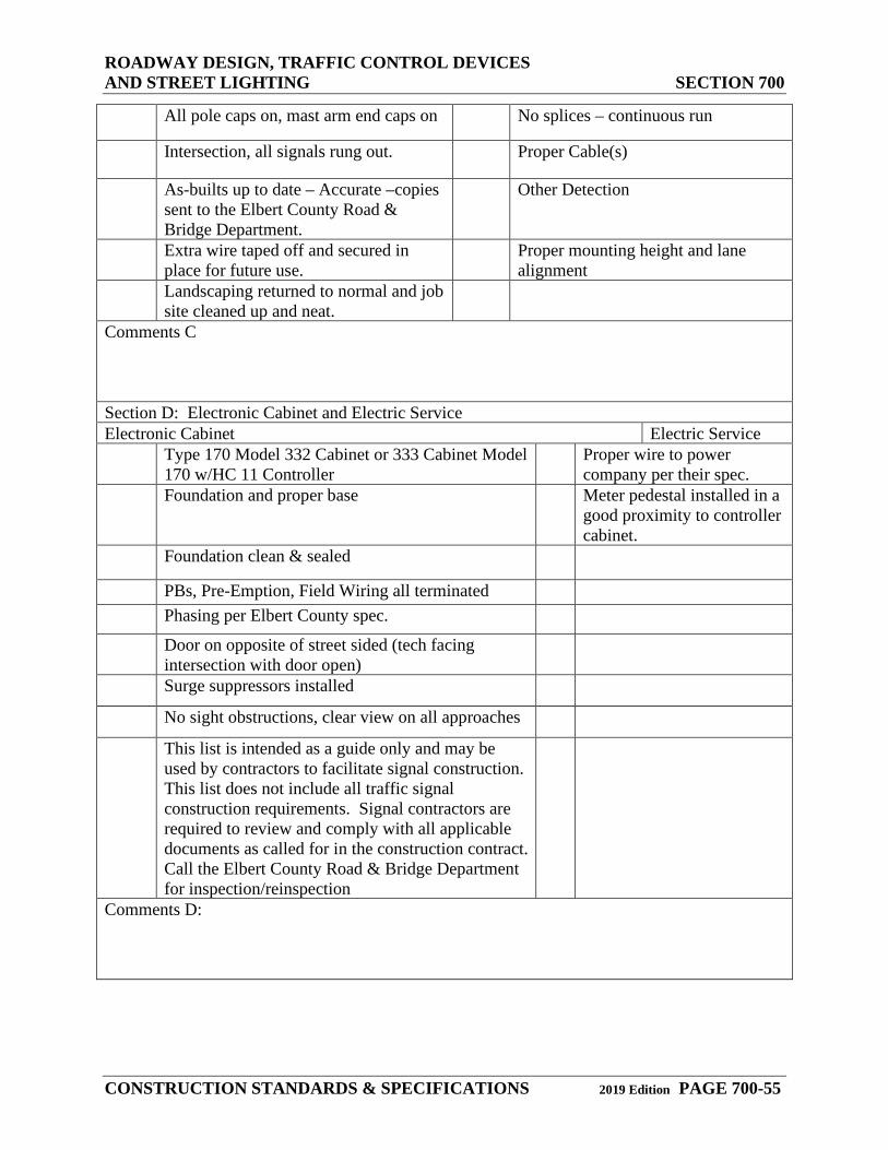
ROADWAY DESIGN, TRAFFIC CONTROL DEVICES AND STREET LIGHTING SECTION 700
CONSTRUCTION STANDARDS & SPECIFICATIONS 2019 Edition PAGE 700-55
All pole caps on, mast arm end caps on
No splices – continuous run
Intersection, all signals rung out.
Proper Cable(s)
As-builts up to date – Accurate –copies sent to the Elbert County Road & Bridge Department.
Other Detection
Extra wire taped off and secured in place for future use.
Proper mounting height and lane alignment
Landscaping returned to normal and job site cleaned up and neat.
Comments C Section D: Electronic Cabinet and Electric Service Electronic Cabinet Electric Service
Type 170 Model 332 Cabinet or 333 Cabinet Model 170 w/HC 11 Controller
Proper wire to power company per their spec.
Foundation and proper base
Meter pedestal installed in a good proximity to controller cabinet.
Foundation clean & sealed
PBs, Pre-Emption, Field Wiring all terminated
Phasing per Elbert County spec.
Door on opposite of street sided (tech facing intersection with door open)
Surge suppressors installed
No sight obstructions, clear view on all approaches
This list is intended as a guide only and may be used by contractors to facilitate signal construction. This list does not include all traffic signal construction requirements. Signal contractors are required to review and comply with all applicable documents as called for in the construction contract. Call the Elbert County Road & Bridge Department for inspection/reinspection
Comments D:
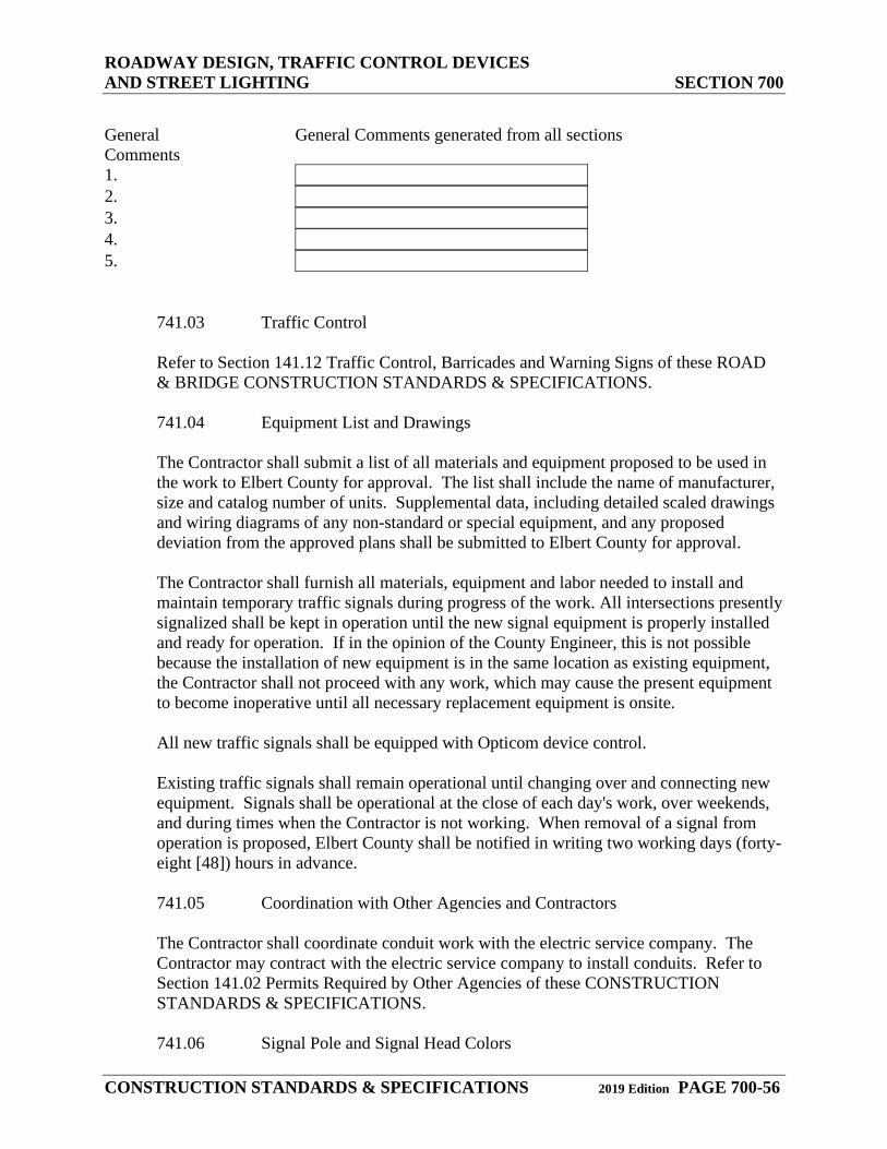
ROADWAY DESIGN, TRAFFIC CONTROL DEVICES AND STREET LIGHTING SECTION 700
CONSTRUCTION STANDARDS & SPECIFICATIONS 2019 Edition PAGE 700-56
General Comments
General Comments generated from all sections
1.
2.
3.
4.
5.
741.03 Traffic Control
Refer to Section 141.12 Traffic Control, Barricades and Warning Signs of these ROAD & BRIDGE CONSTRUCTION STANDARDS & SPECIFICATIONS.
741.04 Equipment List and Drawings
The Contractor shall submit a list of all materials and equipment proposed to be used in the work to Elbert County for approval. The list shall include the name of manufacturer, size and catalog number of units. Supplemental data, including detailed scaled drawings and wiring diagrams of any non-standard or special equipment, and any proposed deviation from the approved plans shall be submitted to Elbert County for approval.
The Contractor shall furnish all materials, equipment and labor needed to install and maintain temporary traffic signals during progress of the work. All intersections presently signalized shall be kept in operation until the new signal equipment is properly installed and ready for operation. If in the opinion of the County Engineer, this is not possible because the installation of new equipment is in the same location as existing equipment, the Contractor shall not proceed with any work, which may cause the present equipment to become inoperative until all necessary replacement equipment is onsite.
All new traffic signals shall be equipped with Opticom device control.
Existing traffic signals shall remain operational until changing over and connecting new equipment. Signals shall be operational at the close of each day's work, over weekends, and during times when the Contractor is not working. When removal of a signal from operation is proposed, Elbert County shall be notified in writing two working days (forty-eight [48]) hours in advance.
741.05 Coordination with Other Agencies and Contractors
The Contractor shall coordinate conduit work with the electric service company. The Contractor may contract with the electric service company to install conduits. Refer to Section 141.02 Permits Required by Other Agencies of these CONSTRUCTION STANDARDS & SPECIFICATIONS.
741.06 Signal Pole and Signal Head Colors
ROADWAY DESIGN, TRAFFIC CONTROL DEVICES AND STREET LIGHTING SECTION 700
CONSTRUCTION STANDARDS & SPECIFICATIONS 2019 Edition PAGE 700-57
Traffic signal pole primer/rust inhibitor shall be Benjamin Moore & Co. Acrylic Metal Primer MO4-01. The finish coat shall be Benjamin Moore & Co. Impervex Latex High Gloss Metal & Wood Enamel 309, “Gray” Paint Spec. 3091B-10RX-3BK-9BB-8TG per gallon.
All traffic signal heads shall be Federal Yellow in color, and the specific color shall be determined by the County Engineer.
742.00 Conduit
742.01 General
Conduit runs shown on the approved plans are tentative as to routing and may be changed, as directed by the Elbert County Inspector/Representative, to avoid underground obstructions. Any change in location from those shown on the approved plans shall require the prior approval of the County Engineer and shall be accurately recorded on as-built drawings in accordance with Section 161.00 Construction Plan Requirements of these CONSTRUCTION STANDARDS & SPECIFICATIONS.
742.02 Materials
All conductors shall be run in conduit except when run in metal poles. Conduit shall be Schedule 40, Type 2 PVC as specified in the NEC. Conduits shall be high-impact type that complies with industry standards and Commercial Standard No. CS-207-60. Each length of conduit and all PVC fittings (expansion joints, couplings, adapters, etc.) shall bear the label of Underwriters Laboratories, Inc. Conduit shall be sized as indicated on the approved plans.
PVC conduit shall be cut with a hacksaw and all ends squared and trimmed after cutting to remove rough edges. Connections shall be the solvent weld type except where the connection is made to a steel conduit, in which case the coupling shall be threaded on the metal conduit side.
Solvent weld joints shall conform to the PVC manufacturer's recommendations. PVC conduit shall be used only for underground installations. All conduit used above ground shall be galvanized steel.
A bare or green insulated #10 AWG copper conductor shall be run continuously in all conduit used for traffic signal circuits for bonding and grounding purposes.
Existing underground conduit that is incorporated into a new system shall be cleaned with a mandrel and compressed air.
742.03 Installation
ROADWAY DESIGN, TRAFFIC CONTROL DEVICES AND STREET LIGHTING SECTION 700
CONSTRUCTION STANDARDS & SPECIFICATIONS 2019 Edition PAGE 700-58
Excavations for conduit shall be two (2) inches wider than the outside diameter of the conduit. Backfilling of the conduit trenches shall be accomplished in accordance with all applicable portions of Section 350.00 Trenching, Backfilling and Compacting of these CONSTRUCTION STANDARDS & SPECIFICATIONS. A nylon pull string shall be left in each conduit run for any future pulling of conductors. When trenching in pavement, the cut in the pavement shall be no wider than the width of the trench Road & Bridge Superintendent / Elbert County Engineer approval shall be required for cutting pavement less than five (5) years old, and special requirements may apply.
Conduit shall be installed not less than thirty (30) inches below the top back of curb grade. Conduits under railroad tracks shall not be less than forty-two (42) inches below the bottom of the tie, and/or as specified by railroad code. Conduit smaller than three-fourths (¾) inch electrical trade size shall not be used unless otherwise specified on the approved plans; however, grounding jumpers at service points may be enclosed in one-half (½) inch conduit.
Conduit size shall be consistent for the entire length of the run from outlet to outlet, and no reducing couplings shall be allowed. Conduits terminating in poles, cabinets, or pedestal bases shall extend above the foundation a maximum of four (4) inches and a minimum of two (2) inches and slope toward pole hand holes or transformer base openings.
Conduit entering pull boxes shall terminate a minimum of one (1) inch and a maximum of three (3) inches inside the box wall and two (2) inches minimum or four (4) inches maximum above the bottom and shall be sloped to facilitate convenient pulling of the wires or cables. Conduit entering through the side of a pull box shall be located near the sides and ends of the box in order to leave the major portion of the box clear. Conduits shall enter freely through boxes for allowance of expansion and contraction. Conduit required to be terminated, stubbed, and plugged shall be shown on the plans as directed by the County Engineer. All conduit ends shall be capped with standard conduit caps until the wiring is started. When caps are removed, the threaded ends shall be provided with approved insulated metal ground bushings.
The location of all conduit ends under curbs or behind structures shall be marked with a “Y”, which is at least three (3) inches high, cut into the face of the curb or wall directly above the conduit. These locations shall be shown on the Record Documents. Refer to Section 211.02 Record Documents of these CONSTRUCTION STANDARDS & SPECIFICATIONS.
Conduit bends, except for factory bends, shall have a radius of not less than six (6) times the inside diameter of the conduit. Where factory bends are not used, conduit shall be bent without crimping or flattening, using the longest radius practicable. Conduit entering controller cabinets shall be packed with duct seal after wiring is installed to prevent the entrance of gases. Existing underground conduit to be incorporated into a new system shall be cleaned with a mandrel and compressed air.
ROADWAY DESIGN, TRAFFIC CONTROL DEVICES AND STREET LIGHTING SECTION 700
CONSTRUCTION STANDARDS & SPECIFICATIONS 2019 Edition PAGE 700-59
Bends in all PVC conduit shall comply with the NEC or local codes governing bending radius and number of bends allowed for rigid conduit.
When PVC conduit is installed for future use, each end shall be capped with a PVC cap. For locating purposes, a galvanized, l2-gauge steel plate twelve (12) inches square shall be placed over each conduit end.
743.00 Cable and Conductors
743.01 General
Cable and conductors shall comply with the International Municipal Signal Association (IMSA) and the approved plans. All wire shall bear the label of Underwriters Laboratories, Inc.
Insulated conductors shall be shipped in splice-free continuous lengths, in cartons or on new-bolted-type non-returnable reels plainly and indelibly marked with the name of the manufacturer, net weight, size (AWG) and length of the wire. NO SPLICES SHALL BE ALLOWED IN THE WIRE. A heavy covering of cardboard or burlap shall be used to protect the wire and reels during shipment and handling.
743.02 Multiconductor Cable
Multiconductor cable shall comply with IMSA Specification 19.1, except that the conductors shall be stranded. Conductor color-coding shall comply with Table II of IMSA Specification 19.1 for unpaired conductor cables. Color-coding for tracers shall run spiral and be impregnated into the conductor insulation.
The wiring of signal heads shall comply with IMSA Specification 7. Single conductor wire shall not be used for wiring signal heads.
743.03 Wiring Installation
Wiring shall comply with the NEC and the National Electric Manufacturers Association (NEMA) Code. Wiring within cabinets and junction boxes shall be neatly arranged and laced. Flaxsoap, or other approved lubricant, may be used for inserting conductors in conduit. No splices of cable shall be permitted in the conduit.
In all signal designs, separate conduits shall be shown for separate low voltage and high voltage conductors on the plane. Signal conductors shall be run in conduits separate from the low voltage detector lead-in.
All loop detector and lead-in wire shall run from loop detectors to the cabinet with no splicing.
Tags for identification of wires shall be furnished and installed by the contractor at cabinet locations, at pull boxes, and at terminating points, or as directed by the Elbert
ROADWAY DESIGN, TRAFFIC CONTROL DEVICES AND STREET LIGHTING SECTION 700
CONSTRUCTION STANDARDS & SPECIFICATIONS 2019 Edition PAGE 700-60
County Inspector/Representative. A permanent fiber or PVC tag shall be used. Tags shall be marked as indicated on the wire layout sheets and shall indicate the direction of the run and pole number of other locations of termination points for the wire run. Confirm that spare wires are not connected to any junction. All spare wires shall be tagged and identified as spare with appropriate numbers as shown on the layout sheets. The ends of the spare wires shall be pulled into the terminal compartment or cabinet.
All wiring between the controller and the signal faces shall be multiconductor cable. The individual conductor shall be l4 gauge stranded copper wire. Separate multiconductor cables for each signal phase shall be installed around the intersection and marked with colored phasing tape at the controller and at each splice point in the pull boxes and pole bases.
743.04 Connections to Signal Heads, Pushbutton Switches and Traffic Controllers
All cable wires shall be secured to screw-type terminals in traffic signal heads, pedestrian pushbutton switches, and the traffic controller. The connectors shall be the spade-tongue type and affixed to the conductors using a tool designed specifically for the connection of the connectors to the conductors, unless Phoenix blocks are being used in the cabinet.
743.05 Wire Splicing Locations
Splices shall only be made in pole bases.
743.06 Wire Bonding and Grounding
Metallic cable sheaths, conduit, metal poles and pedestals shall be bonded to form a continuous and effectively grounded system. Bonding jumpers shall be #l0 AWG copper wire, or larger, as required. Grounding of conduit and neutral at the service point shall be #8 AWG copper wire, or larger, as required. At each controller, a ground rod (electrode) shall be installed. Each ground rod shall be a one-piece solid copper rod, a minimum of one-half (½) inch in diameter and eight (8) feet in length. The rod shall be driven into the ground to a minimum depth of seven (7) feet. The ground wire shall be spliced together at the termination points and shall connect to the neutral bar at the service facility, load center cabinet, or control cabinet.
744.00 Electric Service Connection
The Contractor shall be responsible for coordinating the electric service connection with the electric service company. Electric service connections shall be made by the Electric Service Company. The contractor shall furnish two (2) conductor 6-gauge wire from the controller to the pull box, leaving two (2) feet extra of wire in the pull box.
Service points shown on the approved plans are approximate. The exact location shall be determined in the field by the Contractor, the Elbert County Inspector/Representative, and the electric service company.
ROADWAY DESIGN, TRAFFIC CONTROL DEVICES AND STREET LIGHTING SECTION 700
CONSTRUCTION STANDARDS & SPECIFICATIONS 2019 Edition PAGE 700-61
The Contractor shall furnish and install conduit and conductors to the service points as shown on the approved plans. Conduit for traffic signal service shall not be less than two (2) inches in size.
Conduit and wiring specified in the wire layout sheets and shown on the approved plans shall be furnished and installed from service pole to the controller cabinet, or to the location shown on the approved plans.
745.00 Concrete Foundations
745.01 General
Foundations shall be composed of concrete that complies with Section 800 Concrete Mix Design and Construction of these. Foundations for all poles, standards, pedestals, and cabinets as shown on the approved plans, shall rest on firm ground. Forms required for cast-in-place bases shall be true to line and grade, rigid, and securely braced.
Both forms and ground, which contact the concrete, shall be thoroughly moistened prior to placing concrete. Conduit stubs and anchor bolts shall be placed in proper position and securely held in place by a template while concrete is being placed and until the concrete has properly set. After placing concrete, the anchor bolts shall be raised and lowered individually to eliminate air pockets and to align the anchor bolts prior to concrete setting. Any deviations in foundation location proposed by Contractor shall require County Engineer approval.
745.02 Poles, Standards and Pedestal Foundations
Poles, standards and pedestals shall not be installed until the foundation concrete has set at least seven (7) days. Foundations of high-strain poles shall set a minimum of ten (10).
Foundations for all poles shall have a flush top. In each case, the maximum distance behind the curb for pole locations is desired. In locations where the roadway is not curbed, the top of the foundations shall be six and one-quarter (61/4) inches above the grade of the edge of the pavement. Where foundations are located in the sidewalk, the foundation shall be two (2) inches above the surface of the sidewalk, and expansion material shall be placed between the foundation and the sidewalk, with the top of the expansion material level with the sidewalk surface. Foundations for traffic signal control cabinets that are located in sidewalks shall extend above the sidewalk surface as shown on the plans.
746.00 Traffic Signal Controllers
746.01 Signal Phasing and Tape Colors
Refer to Section 741.02 Inspection of these CONSTRUCTION STANDARDS & SPECIFICATIONS.
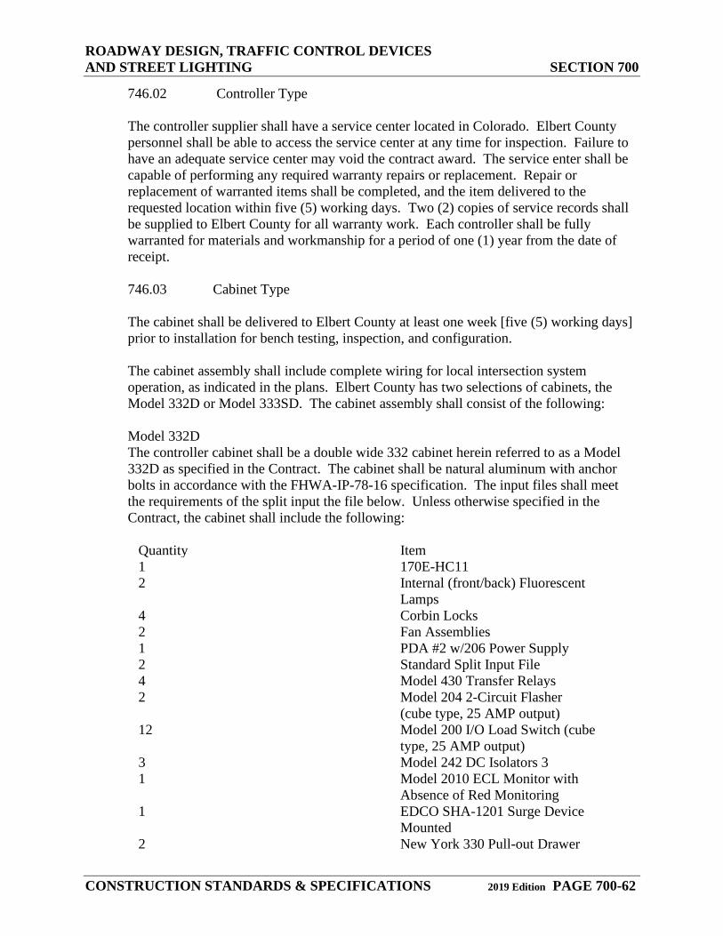
ROADWAY DESIGN, TRAFFIC CONTROL DEVICES AND STREET LIGHTING SECTION 700
CONSTRUCTION STANDARDS & SPECIFICATIONS 2019 Edition PAGE 700-62
746.02 Controller Type
The controller supplier shall have a service center located in Colorado. Elbert County personnel shall be able to access the service center at any time for inspection. Failure to have an adequate service center may void the contract award. The service enter shall be capable of performing any required warranty repairs or replacement. Repair or replacement of warranted items shall be completed, and the item delivered to the requested location within five (5) working days. Two (2) copies of service records shall be supplied to Elbert County for all warranty work. Each controller shall be fully warranted for materials and workmanship for a period of one (1) year from the date of receipt.
746.03 Cabinet Type
The cabinet shall be delivered to Elbert County at least one week [five (5) working days] prior to installation for bench testing, inspection, and configuration.
The cabinet assembly shall include complete wiring for local intersection system operation, as indicated in the plans. Elbert County has two selections of cabinets, the Model 332D or Model 333SD. The cabinet assembly shall consist of the following:
Model 332D The controller cabinet shall be a double wide 332 cabinet herein referred to as a Model 332D as specified in the Contract. The cabinet shall be natural aluminum with anchor bolts in accordance with the FHWA-IP-78-16 specification. The input files shall meet the requirements of the split input the file below. Unless otherwise specified in the Contract, the cabinet shall include the following:
Quantity Item 1 170E-HC11 2 Internal (front/back) Fluorescent
Lamps 4 Corbin Locks 2 Fan Assemblies 1 PDA #2 w/206 Power Supply 2 Standard Split Input File 4 Model 430 Transfer Relays 2 Model 204 2-Circuit Flasher
(cube type, 25 AMP output) 12 Model 200 I/O Load Switch (cube
type, 25 AMP output) 3 Model 242 DC Isolators 3 1 Model 2010 ECL Monitor with
Absence of Red Monitoring 1 EDCO SHA-1201 Surge Device
Mounted 2 New York 330 Pull-out Drawer
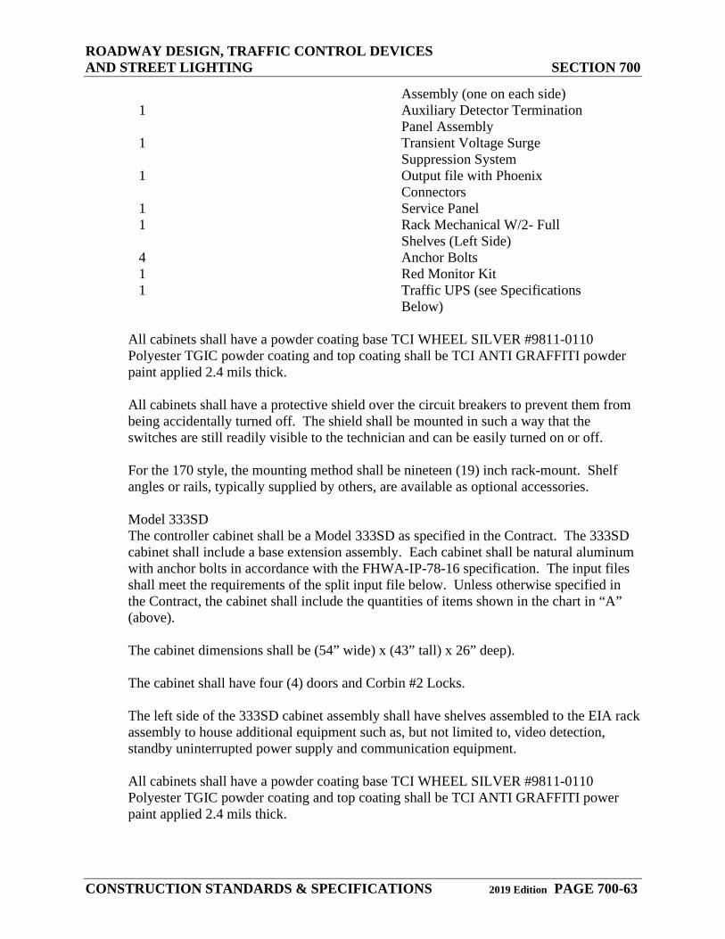
ROADWAY DESIGN, TRAFFIC CONTROL DEVICES AND STREET LIGHTING SECTION 700
CONSTRUCTION STANDARDS & SPECIFICATIONS 2019 Edition PAGE 700-63
Assembly (one on each side) 1 Auxiliary Detector Termination
Panel Assembly 1 Transient Voltage Surge
Suppression System 1 Output file with Phoenix
Connectors 1 Service Panel 1 Rack Mechanical W/2- Full
Shelves (Left Side) 4 Anchor Bolts 1 Red Monitor Kit 1 Traffic UPS (see Specifications
Below)
All cabinets shall have a powder coating base TCI WHEEL SILVER #9811-0110 Polyester TGIC powder coating and top coating shall be TCI ANTI GRAFFITI powder paint applied 2.4 mils thick.
All cabinets shall have a protective shield over the circuit breakers to prevent them from being accidentally turned off. The shield shall be mounted in such a way that the switches are still readily visible to the technician and can be easily turned on or off.
For the 170 style, the mounting method shall be nineteen (19) inch rack-mount. Shelf angles or rails, typically supplied by others, are available as optional accessories.
Model 333SD The controller cabinet shall be a Model 333SD as specified in the Contract. The 333SD cabinet shall include a base extension assembly. Each cabinet shall be natural aluminum with anchor bolts in accordance with the FHWA-IP-78-16 specification. The input files shall meet the requirements of the split input file below. Unless otherwise specified in the Contract, the cabinet shall include the quantities of items shown in the chart in “A” (above).
The cabinet dimensions shall be (54” wide) x (43” tall) x 26” deep).
The cabinet shall have four (4) doors and Corbin #2 Locks.
The left side of the 333SD cabinet assembly shall have shelves assembled to the EIA rack assembly to house additional equipment such as, but not limited to, video detection, standby uninterrupted power supply and communication equipment.
All cabinets shall have a powder coating base TCI WHEEL SILVER #9811-0110 Polyester TGIC powder coating and top coating shall be TCI ANTI GRAFFITI power paint applied 2.4 mils thick.
ROADWAY DESIGN, TRAFFIC CONTROL DEVICES AND STREET LIGHTING SECTION 700
CONSTRUCTION STANDARDS & SPECIFICATIONS 2019 Edition PAGE 700-64
All cabinets shall have a protective shield over the circuit breakers to prevent them from being accidentally turned off. The shield shall be mounted in such a way that the switches are still readily visible to the technician and can be easily turned on or off.
For the 170 style, the mounting method shall be nineteen (19) inch rack-mount. Shelf angles or rails, typically supplied by others, are available as optional accessories.
746.04 Signal Cabinet Base
The ground mounted fiberglass signal cabinet base shall be installed level and as shown on the approved plans or as directed by the County Engineer. The seam between the base and the cabinet shall be caulked both inside and outside the controller base to prevent water seepage. The cabinet shall be set flush on the cabinet base.
746.05 Signal Cabinet Locations
Visual aesthetics should be considered in the location of signal cabinets. The location of the cabinets shall be approved by the DPW DIRECTOR DESIGNEE.
746.06 Cycle Length
The County Engineer shall determine signal timing.
746.07 Spread Spectrum
The following shall be the minimum requirements for a Wireless Interconnect Package: Operate in the license-free, spread spectrum band (902-928 MHz), utilizing frequency hopping technology 139 user-selectable channels, with 62 available hopping sequences. Two (2) shall be non-overlapping. Completely configurable via included software. Software features to provide “remote programming, remote maintenance and spectrum analyzer” included. An RS232 interface capable of 1200 bps to 115.2 Kbps with an 8 or 9 bit format or 1200 bps Bell 202 FSK (2 or 4-wire) A maximum of 8 msec end-to-end latency LED indicators for PWR, TX DATA, RX DATA and the active data port DB9F connector for RS232 port and RJ22 for FSK Receiver sensitivity of -110dBm @ 10-6 BER Operating temperature of -40 to +80 degrees C Operate with voltages between 6 VDC and 30 VDC., with a typical current draw of <100mA Radio sleep mode with a maximum current draw of <1 uA Programmable for RF output levels of 1mW, 10mW, 100mW or 1 Watt Provide 16-bit CRC error checking with auto re-transmit Available as Shelf Mounted, Rack-Mounted, or NEMA 4X Weatherproof Versions
ROADWAY DESIGN, TRAFFIC CONTROL DEVICES AND STREET LIGHTING SECTION 700
CONSTRUCTION STANDARDS & SPECIFICATIONS 2019 Edition PAGE 700-65
Controller hardware and software ready for use upon installation Built-in store-and-forward repeater Encom COMMPAKTM Model 5100R or equivalent Compatible with, and plug directly into, 170/ TSI detector rack Draws operating power from detector card cage RP TNC-F antenna connector RSSI signal strength LEDS
747.08 Uninterruptible Power System
Operation: The Traffic UPS shall be capable of producing-simultaneously—fully regenerated, conditioned and true sine wave, standby and continuous AC outputs. Suggested operating mode for respective outputs during power failure: Continuous output provided for signal controllers and modems; Standby output provided for signals in flash mode operation (optional delay timer available for short-term battery run under full cycling operation). Up to the maximum rating, the Traffic UPS shall be capable of running any combination of signal heads, whether Incandescent, LED or Neon, by any manufacturer, regardless of power factor, without overdriving the power factor LED heads which may cause early degradation, low luminosity or early signal failure. Upon loss of utility power, the Traffic UPS shall insert battery power into the system via a supplied Power Interface Module (PIM). In case of UPS failure and/or battery depletion, the PIM will ensure that the UPS will drop out and, upon return of utility power, the traffic control system will default to normal operating mode. The Power Interface Module shall enable removal and replacement of the Traffic UPS without shutting down the traffic control system (i.e. “hot swap” capability). Connectors shall be equipped with a “safety interlock” feature. For 170 or “California” style cabinets, upon loss of power the Traffic UPS shall actuate the existing Flash Transfer Relays (FRS) and Mercury Contractor (MC) to force the traffic control system into Flash Mode operation. Existing Flasher Modules and Flash Transfer Relays shall be utilized. To facilitate emergency crews and police activities, the Traffic UPS shall be compatible with police panel functions (i.e. “Signals OFF” switch must remove power to the field wiring even when on UPS/battery power). The Traffic UPS shall not duplicate or take over flash operation or flash transfer relay functions. The Traffic UPS shall be capable of providing continuous, fully conditioned, regulated, sinusoidal (AC) power to selected devices such as signal controllers, modems, communications, hubs, NTCIP adapters and video equipment.
The Traffic UPS shall consist of three major components: The Electronics Module, the Power Interface Module and the Battery System.
The Electronics Module shall consist of the following: Dimensions: Rack-mount: Width = 19”, Depth = 12”, Height = 3.5” (2U)
ROADWAY DESIGN, TRAFFIC CONTROL DEVICES AND STREET LIGHTING SECTION 700
CONSTRUCTION STANDARDS & SPECIFICATIONS 2019 Edition PAGE 700-66
Shelf-mount: Width = 19”, Depth = 12”, Height = 3.5” Wall-mount/Unistrut Rail mount: Width = 6.9”, Depth = 9.5”, Height = 16” Separate Power-Interface Module = Width = 6”, Depth = 2.8”, Height = 9” Weight: UPS: 20lbs., Shipping weight: 25lbs. True sine wave, high frequency inverter utilizing IGBT technology 3-stage, temperature compensated, battery charger For connection from the electronics module to the power interface module and battery system, dedicated harnesses shall be provided with quick-release, keyed, circular connections and braided nylon sleeving over all conductors Local and remote control of UPS functions Local and remote communications capabilities Shall be capable of accepting an NTCIP ready adapter or a spread spectrum radio modem Separate Power Interface Module (PIM) for inserting power safely and reliably.
Mounting Configuration: NEMA Style: mounting method shall be shelf-mount or wall-mount. 170 Style: mounting method shall be 19” rack-mount. Shelf angles or rails, typically supplied by others, are available as optional accessories. External: A separate, stand-alone, pad-mounted, outdoor (NEMA 3R) enclosure shall be available should there be inadequate room in the signal cabinet, or should the consulting/Engineer prefer independent, external mounting. Batter System: The battery shall be comprised of extreme temperature, deep cycle, AGM/VRLA (Absorbed Glass Mat/Valve Regulated Lead Acid) batteries that have been field proven and tested. The battery system shall consist of one or more strings of 6 batteries per string of extreme temperature, deep cycle, AGM/VRLA (Absorbed Glass Mat/Valve Regulated Lad Acid) batteries. Batteries shall be certified to operate at extreme temperatures from -40 degrees C 10 +74 degrees C. The batteries shall be provided with appropriate interconnect wiring and a corrosion-resistant mounting trays and/or brackets appropriate for all the cabinet into which they shall be installed. The interconnect cable shall be protected with abrasion-resistant nylon sheathing. The interconnect cable shall connect to the base module via a quick release circular connector. The circular battery connector shall have interlocking pins to prevent turn-on if batteries are not connected, and to shut off the UPS should the batteries be disconnected. Battery construction shall include heavy-duty, inter-cell connections for low impedance between cells, and heavy-duty plates to withstand shock and vibration. The top cover shall use tongue and groove construction and shall be epoxied to the battery case for maximum strength and durability. An optional lifting handle shall be available on most battery models.
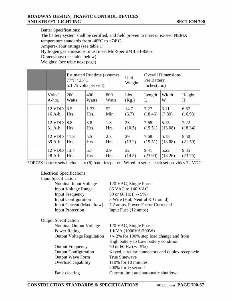
ROADWAY DESIGN, TRAFFIC CONTROL DEVICES AND STREET LIGHTING SECTION 700
CONSTRUCTION STANDARDS & SPECIFICATIONS 2019 Edition PAGE 700-67
Batter Specifications: The battery system shall be certified, and field proven to meet or exceed NEMA temperature standards from -40°C to +74°C. Ampere-Hour ratings (see table 1) Hydrogen gas emissions: must meet Mil-Spec #MIL-B-8565J Dimensions: (see table below) Weights: (see table next page)
Estimated Runtime (assumes
77°F / 25°C, to1.75 volts per cell).
Unit Weight
Overall Dimensions Per Battery Inches(cm.)
Volts/ A-hrs.
200 Watts
400 Watts
800 Watts
Lbs. (Kg.)
Length L
Width W
Height H
12 VDC/ 16 A-h
3.5 Hrs.
1.73 Hrs.
52 Min.
14.7 (6.7)
7.27 (18.46)
3.11 (7.89)
6.67 (16.93)
12 VDC/ 31 A-h
8.8 Hrs.
3.8 Hrs.
1.8 Hrs.
23 (10.5)
7.68 (19.51)
5.15 (13.08)
7.22 (18.34)
12 VDC/ 39 A-h
11.3 Hrs.
5.5 Hrs.
2.3 Hrs.
29 (13.2)
7.68 (19.51)
5.15 (13.08)
8.50 (21.59)
12 VDC/ 48 A-h
13.7 Hrs.
6.7 Hrs.
2.9 Hrs.
32 (14.5)
9.41 (23.90)
5.22 (13.26)
9.35 (23.75)
*OP72X battery sets include six (6) batteries per et. Wired in series, each set provides 72 VDC.
Electrical Specifications: Input Specification
Nominal Input Voltage 120 VAC, Single Phase Input Voltage Range 85 VAC to 140 VAC Input Frequency 50 or 60 Hz (+/- 5%) Input Configuration 3 Wire (Hot, Neutral & Ground) Input Current (Max. draw) 7.2 amps, Power-Factor Corrected Input Protection Input Fuse (12 amps)
Output Specification Nominal Output Voltage 120 VAC, Single Phase Power Rating 1 KVA (1000VA/700W) Output Voltage Regulation +/- 2% for 100% step load change and from High battery to Low battery condition Output Frequency 50 or 60 Hz (+/- 5%) Output Configuration Keyed, circular connectors and duplex receptacle Output Wave Form True Sinewave Overload capability 110% for 10 minutes 200% for ½ second Fault clearing Current limit and automatic shutdown
ROADWAY DESIGN, TRAFFIC CONTROL DEVICES AND STREET LIGHTING SECTION 700
CONSTRUCTION STANDARDS & SPECIFICATIONS 2019 Edition PAGE 700-68
Short circuit protection Current limit and automatic shutdown Efficiency 85% at full load Load Power Factor .7 lagging through unity to .7 leading
Communication, Controls and Diagnosis: Alarm function monitoring through the UPS shall be through a standard DB-9F connector with open collectors 40V@20mA indicating loss of utility power, inverter failure and low battery An RS 232 interface shall be provided via a DB-9F connector to allow full interactive remote computer monitoring and control of the UPS functions Front panel controls shall consist of no less than: Power On, Cold (DC) Start, Alarm Silence, Battery, Test, Bypass Breaker, and DC/Breaker
Environmental Specifications: The UPS shall meet or exceed NEMA temperature standards from -40°C to +74°C. The UPS shall be certified, and field proven to meet or exceed NEMA temperature standards. A certificate of compliance shall be made available upon request.
Reliability: Calculated MTBF shall be 100,000 hours based on component ratings When Bypass and Power Interface Module are included, system MTBF shall increase to 150,000 hours
Options: Battery Tray to hold six (6) OP72A batteries, up to four (4) OP72B or OP72C batteries, and up to three (3) OP72D batteries. Tray is 19” wide for use in 170 type cabinets and mounts on standard RETMA rails. Swing-out Battery Box, mounts on right rail inside back door of 170 type cabinets. Box is designated to hold six (6) OP72A batteries, up to four (4) OP72B or OP72C batteries, and up to three (3)OP72D batteries. Adjustable Delay-timer to provide up to 10 hours of full cycling while on battery before switching to flash mode (only available where 100% low-power/LED signals and ped heads are used). Batteries must be sized properly to fully utilize this feature. Service pedestal-mounting option. One-shot ground pulse to trigger External Start upon return of AC power. Dial-out modem for wireless or land line communication Enhanced battery charger provides accelerated charging capacity (contact factory for details and proper application).
Serviceability & Maintainability: MTTR (Mean-Time-To-Replace or Repair) Electronics: 15 minutes or less Battery System: 15 minutes or less
746.09 Video Detection System
Detection zones shall be installed by Elbert County at signal turn-on.
ROADWAY DESIGN, TRAFFIC CONTROL DEVICES AND STREET LIGHTING SECTION 700
CONSTRUCTION STANDARDS & SPECIFICATIONS 2019 Edition PAGE 700-69
The video detection system shall consist of one video camera, a video detection processor (VDP) that mounts in a standard detector rack, and a detector rack mounted extension module (EM).
The system shall include software that detects vehicles in multiple lanes using only the video image. Detection zones shall be defined using only a video menu and a pointing device to place the zones on a video image. Up to twenty-four (24) detection zones per camera shall be available.
The functional characteristics shall include the following: The VDP shall process video from one source. The source may be a video camera or video tape player. The video shall be input to the VDP in RS170 format and shall be digitized and analyzed in real time. The VDP shall detect the presence of vehicles in up to 24 detection zones per camera. A detection zone shall be approximately the width and length of one car. Detector zones shall be programmed via a menu displayed on a video monitor and a pointing device connected to the VDP. The menu shall facilitate placement of the detection zones. A separate computer shall not be required for programming detection zones. The VDP shall store up to three different detector zone patterns. The VDP can switch to any one of the three different detector patterns within 1 second of user request via menu selection with the pointing device. The VDP shall detect vehicles in real time as they travel across each detector zone. The VDP shall have an RS232 port for communications with an external computer. The VDP shall accept new detector patterns from an external computer through the RS-232 port. The VDP shall send its detector patterns to an external computer through the RS-232 port when requested. The extension module (EM) shall be available to avoid the need to rewire the detector rack, by enabling the user to plug an extension module into the appropriate slot in the detector rack. The extension module shall be connected to the VDP by a 10-wire cable with modular connectors and shall output contact closures in accordance with user selectable channel assignments.
The following describes vehicle detection at the intersection: A single detection zone shall be able to replace multiple loops. Detection zones may be placed together to indicate vehicle presence on a single phase of traffic movement. Layout of detection zones shall be done by using a pointing device and a graphical interface built into the VDP to mark the detection zones on the video image from each video camera. Up to three (3) detection zone patterns shall be saved within the VDP memory to prevent loss during power outages. The selection of the detection zone pattern for current use shall be done through a menu. It shall be possible to activate a detection zone pattern for a camera from VDP memory and have that detection zone pattern displayed within 1 second of activation. When a vehicle is detected crossing a detection zone, the detection zone shall flash a symbol on the screen to confirm the detection of the vehicle.
ROADWAY DESIGN, TRAFFIC CONTROL DEVICES AND STREET LIGHTING SECTION 700
CONSTRUCTION STANDARDS & SPECIFICATIONS 2019 Edition PAGE 700-70
Detection shall be at least 98% accurate in good weather conditions and at least 96% accurate under adverse weather conditions (rain, snow, or fog). Detection accuracy is dependent upon site geometry, camera placement, camera quality and detection zone location, and these accuracy levels do not include allowances for occlusion or poor video due to camera location or quality. Detector placement shall not be more distant from the camera than a distance of ten times the mounting height of the camera. The VDP shall provide up to 8 channels of vehicle presence detection through a standard detector rack edge connector and one or more extension modules. The VDP shall provide DZR to enable normal detector operation of existing zones except the one being added or modified during the setup process. The VDP shall output a constant call on any detection channel corresponding to a zone being modified.
For VDP and EM Hardware: The VDP and extension module shall be specifically designed to mount in a standard detector rack, using the edge connector to obtain power and provide contact closure outputs. No adapters shall be required to mount the VDP in a standard detector rack. No detector rack rewiring shall be required. The VDP and extension module shall operate satisfactorily in a temperature range from -29 degrees F to +140 degrees F and a humidity range from 0% Relative Humidity (RH) to 95%RH, non-condensing. The VDP and extension module shall be powered by 24 volts dc. VDP power consumption shall not exceed 450 milliamps. The EM power consumption shall not exceed 100 milliamps. The VDP shall include an RS232 port for serial communications with a remote computer. This port shall be a “D” subminiature connector on the front of the VDP. The VDP shall utilize flash memory technology to enable the loading of modified or enhanced software through the RS232 port and without modifying the VDP hardware. The VDP and extension module shall include detector output pin out compatibility with industry standard detector racks. The front of the VDP shall include detection indications for each channel of detection that display detector outputs in real time when the system is operational. The front of the VDP shall include one BNC video input connection suitable for RS170 video inputs. The video input shall include a switch selectable 75 ohm or high impedance termination to allow camera video to be routed to other devices, as well as input to the VDP for vehicle detection. The front of the VDP shall include one BNC video output providing real time video output which can be routed to other devices.
The following describes the camera: The camera shall produce a useable video image of the bodies of vehicles under all roadway lighting conditions, regardless of time of day. The minimum range of scene luminance over which the camera shall produce a useable video image shall be the minimum range from nighttime to daytime, but not less than the range 0.5 lux to 10,000 lux. The camera shall use a CCD sensing element and shall output monochrome video with resolution of not less than 350 lines vertical and 380 lines horizontal. The camera shall include automatic electronic shutter control based upon average scene luminance. The camera shall include a variable focal length lens with variable focus and zoom that can be adjusted, without opening up the camera housing, to suit the site geometry.
ROADWAY DESIGN, TRAFFIC CONTROL DEVICES AND STREET LIGHTING SECTION 700
CONSTRUCTION STANDARDS & SPECIFICATIONS 2019 Edition PAGE 700-71
The camera shall be housed in an environmentally sealed enclosure. The camera enclosure shall be equipped with a sun shield that prevents sunlight from directly entering the lens. The sunshield shall include a provision for water diversion to prevent water from flowing in the cameras field of view. The camera enclosure with sunshield shall be less than 6” diameter, less than 26” long, and shall weigh less than 12 pounds when the camera and lens are mounted inside the enclosure. The camera enclosure shall include a thermostatically controlled heater to assure proper operation of the lens iris at low temperatures and prevent moisture condensation on the optical faceplate of the enclosure. When mounted outdoors in the enclosure, the camera shall operate satisfactorily in a humidity range from 0% RH to 100% RH. The camera shall be powered by 120 VAC 60 Hz. Power consumption shall be less than 40 watts under all conditions. Recommended camera placement shall be 33 feet above the roadway, and over the traveled way on which vehicles shall be detected. The camera shall view approaching vehicles at a distance not to exceed 350 feet for reliable detection. The camera enclosure shall be equipped with separate, weather-tight connections for power and video cables at the rear of the enclosure to allow diagnostic testing and viewing of video at the camera while the camera is installed on a mast arm or pole. Video and power shall not be connected with the same connector. The video signal output by the camera shall be in RS170 format. The video signal shall be fully isolated from the camera enclosure and power cabling. Coaxial cable for transmission of video signals shall be Belden #8281 or equivalent. This cable shall be suitable for installation in conduit or overhead with appropriate span wire. BNC plug connectors should be used at both the camera and cabinet ends. The coaxial cable, BNC connector and crimping tool shall be approved by the supplier of the video detection system and the manufacturer's instructions shall be followed to ensure proper connection. The power cabling shall be 16 AWG three conductor cable. The cabling shall comply with the National Electric Code, as well as local electrical codes.
747.00 Light Emitting Diode (LED) Lights
When specified in the plans, the optical units of the red indications in all vehicle signal faces shall be LED Traffic Signal Section Optical Units. The LED optical units shall be installed in accordance with the manufacturer’s instructions. The LED optical units shall not be paid for separately but shall be included in the cost of the traffic signal face.
747.01 Wattage
The wattage shall be a maximum of thirty-five (35) watts for a 12-inch ball display.
The maximum total harmonic current distortion (THD) shall be less than 20%, and the power factor shall be greater than 90%.
THD and power factor requirements shall be waived for products designed to operate at less than fourteen (14) watts.
747.02 Voltage
ROADWAY DESIGN, TRAFFIC CONTROL DEVICES AND STREET LIGHTING SECTION 700
CONSTRUCTION STANDARDS & SPECIFICATIONS 2019 Edition PAGE 700-72
Operating voltage shall be between eighty-five (85) and one hundred thirty (130) VAC. Electronic circuitry shall assure proper operation of the load switch and monitor in the control cabinet.
747.03 Circuit Configuration
The LEDs shall be connected to form multiple series circuits. All series circuits shall be interconnected at intervals, forming sub circuits not exceeding fifteen (15) LEDs for the ball and arrow signals. In the event of an LED failure, these sub circuits shall limit the number of extinguished LEDs to no more than four (4) percent of the total on the ball and six (6) percent of the total on the arrow lamp.
747.04 Enclosure
The enclosure shall be dust and water-resistant and shall be approved by the County Engineer.
747.05 Operating Temperature
Operating temperature shall be between -40 degrees F and 185 degrees F.
747.06 Lens
The lens shall be replaceable, polycarbonate (UV stabilized “Lexan”) convex lens; meet ITE color standards; minimum of one-eighth (⅛) inch thickness; and minimum light transmittance of 92%, free from bubbles, flaws and other imperfections. Non-polycarbonate tinted lenses shall be accepted provided that these meet ITE color standards. Chromacity shall be uniform across the face of the lens. Non-polycarbonate lenses shall also meet three and one-half (3-½) foot drop tests.
747.07 Candlepower Distribution
Candlepower distribution shall meet minimum ITE specifications. Intensity shall be measured uniform across the face of the lens. Brightness shall be maintained in the event of voltage fluctuations or voltage drops.
747.08 Beam Spread
The beam spread shall be thirty (30) degrees to each side.
747.09 Manufacturer’s Warranty
The manufacturer’s warranty shall include a repair or replacement guarantee of five (5) years and shall cover all except for accidental damage.
748.00 Speed Monitor Display (Speed Awareness Sign)
ROADWAY DESIGN, TRAFFIC CONTROL DEVICES AND STREET LIGHTING SECTION 700
CONSTRUCTION STANDARDS & SPECIFICATIONS 2019 Edition PAGE 700-73
748.01 Size
For speeds of forty-five (45) mph and faster, a sign should have as a minimum eighteen (18) inch LED display. In residential areas a twelve (12) inch LED display is required as a minimum. The radar antenna and display to be mounted behind the display windows shall be three-sixteenths (3/16) inch thick non-glare Lexan polycarbonate material or approved equal. The housing shall be at least one-eighth (⅛) inch thick aluminum with a baked powder coat enamel finish. Stainless steel tamper resistant hardware shall be standard. Brightness shall adjust automatically to ambient light conditions.
748.02 Programming
Programming of the display shall be with “one-button” access. Button shall be accessed by a key lock.
748.03 Violator Alert
Violator alert shall be set with “one button” programming in increments of five (5) mph. The display shall not indicate a speed if vehicle is exceeding the pre-set threshold limit. The display shall show violator alert option “Slow Down” in red LED or shall show flashing red and blue bars in LED.
748.04 Radar Unit
The radar unit shall be Decatur Electronics S12 or equal. The unit should use K band frequency or higher. The unit shall be single direction only. The unit shall be Federal Communications Commission (FCC) certified.
749.00 Traffic Signal Start-Up Procedures
Elbert County shall install all signal timings prior to the first turn-on. At the first turn-on, the signal shall be set in “Flash” mode for one week—to include a weekend—prior to starting normal operation. The Contractor shall have a representative present at the first turn-on (“Flash” mode) and at the start of normal operation.
750.00 STREET LIGHTING
751.00 Street Lighting Procedure
The Developer shall submit a written request for streetlight design to the electric service company. The Developer shall submit the final streetlight design to the DPW Director or designee Engineer for review and approval. At the time of inspection, all streetlights shall be installed in accordance with these CONSTRUCTION STANDARDS & SPECIFICATIONS and as shown on the approved plans. Developer shall pay the electric service company the total cost of design, materials and installation for all street lighting.
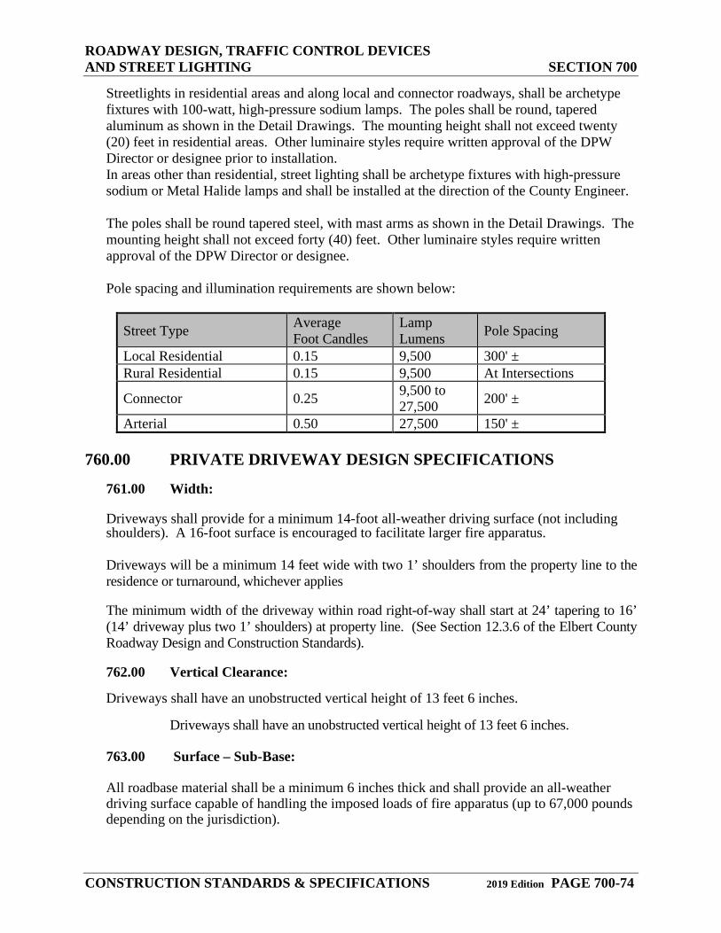
ROADWAY DESIGN, TRAFFIC CONTROL DEVICES AND STREET LIGHTING SECTION 700
CONSTRUCTION STANDARDS & SPECIFICATIONS 2019 Edition PAGE 700-74
Streetlights in residential areas and along local and connector roadways, shall be archetype fixtures with 100-watt, high-pressure sodium lamps. The poles shall be round, tapered aluminum as shown in the Detail Drawings. The mounting height shall not exceed twenty (20) feet in residential areas. Other luminaire styles require written approval of the DPW Director or designee prior to installation. In areas other than residential, street lighting shall be archetype fixtures with high-pressure sodium or Metal Halide lamps and shall be installed at the direction of the County Engineer.
The poles shall be round tapered steel, with mast arms as shown in the Detail Drawings. The mounting height shall not exceed forty (40) feet. Other luminaire styles require written approval of the DPW Director or designee.
Pole spacing and illumination requirements are shown below:
Street Type Average Foot Candles
Lamp Lumens Pole Spacing
Local Residential 0.15 9,500 300' ± Rural Residential 0.15 9,500 At Intersections
Connector 0.25 9,500 to 27,500 200' ±
Arterial 0.50 27,500 150' ± 760.00 PRIVATE DRIVEWAY DESIGN SPECIFICATIONS
761.00 Width:
Driveways shall provide for a minimum 14-foot all-weather driving surface (not including shoulders). A 16-foot surface is encouraged to facilitate larger fire apparatus.
Driveways will be a minimum 14 feet wide with two 1’ shoulders from the property line to the residence or turnaround, whichever applies
The minimum width of the driveway within road right-of-way shall start at 24’ tapering to 16’ (14’ driveway plus two 1’ shoulders) at property line. (See Section 12.3.6 of the Elbert County Roadway Design and Construction Standards).
762.00 Vertical Clearance:
Driveways shall have an unobstructed vertical height of 13 feet 6 inches. Driveways shall have an unobstructed vertical height of 13 feet 6 inches.
763.00 Surface – Sub-Base:
All roadbase material shall be a minimum 6 inches thick and shall provide an all-weather driving surface capable of handling the imposed loads of fire apparatus (up to 67,000 pounds depending on the jurisdiction).
ROADWAY DESIGN, TRAFFIC CONTROL DEVICES AND STREET LIGHTING SECTION 700
CONSTRUCTION STANDARDS & SPECIFICATIONS 2019 Edition PAGE 700-75
763.01 Aggregate surface – sub-base.
All roadbase material shall be a minimum 6” (compacted) and shall provide an all-weather driving surface – sub-base capable of handling the imposed loads of fire apparatus (up to 67,000 pounds depending on the jurisdiction).
The acceptable materials for an all-weather driving surface – sub-base is
Class 5-6 aggregate Class 5-6 recycled concrete Class 5-6 recycled asphalt
Asphalt and concrete paved surfaces accompanied by a Geotech report will also be considered an all-weather surface.
Owner/contractor shall provide Elbert County with test results of the materials used.
763.02 Driveways accessing paved Elbert County/private roads.
All driveways that meet or join paved roads must be paved with asphalt and tacked at the seam.
Depth or thickness of pavement will be 4” minimum compacted.
Drive must be paved from the property line to the edge of the paved portion of the Elbert County/private road. Sub-base under pavement must be 6” (compacted) of the following:
Class 4-7 aggregate Class 4-7 recycled concrete Class 4-7 recycled asphalt
Asphalt and concrete paved surfaces accompanied by a Geotech report will also be considered an all-weather surface.
Paved driveway access from shoulder of road to property line will be part of the final driveway inspection.
Any surface (asphalt, concrete, chip seal, etc.) applied over approved sub-base from property line to house will not be approved or inspected by Elbert County.
764.00 Approach:
All driveways must approach the roadway at a 70 -90 degree angle perpendicular to the intersecting roadway.
All driveways must approach the roadway at a 70 -90 degree angle perpendicular to the intersecting roadway.
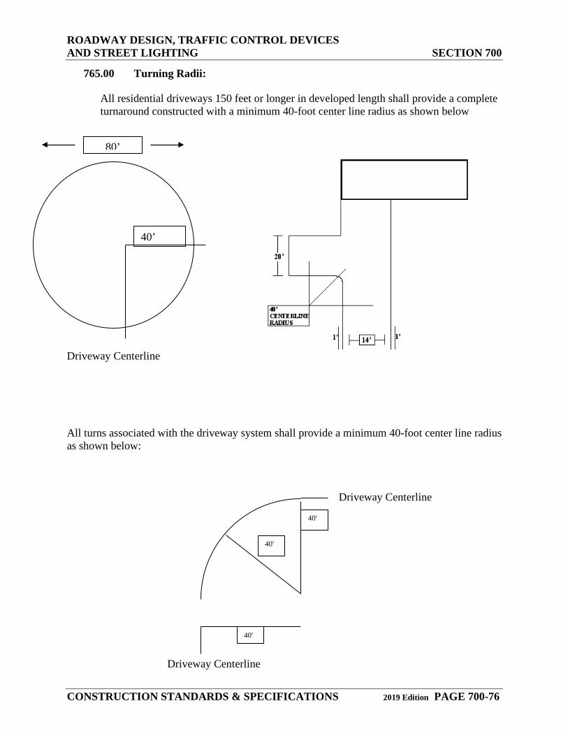
ROADWAY DESIGN, TRAFFIC CONTROL DEVICES AND STREET LIGHTING SECTION 700
CONSTRUCTION STANDARDS & SPECIFICATIONS 2019 Edition PAGE 700-76
765.00 Turning Radii:
All residential driveways 150 feet or longer in developed length shall provide a complete turnaround constructed with a minimum 40-foot center line radius as shown below
Driveway Centerline All turns associated with the driveway system shall provide a minimum 40-foot center line radius as shown below: Driveway Centerline
Driveway Centerline
80’
40’
40'
40'
40'
ROADWAY DESIGN, TRAFFIC CONTROL DEVICES AND STREET LIGHTING SECTION 700
CONSTRUCTION STANDARDS & SPECIFICATIONS 2019 Edition PAGE 700-77
Exceptions: A: Driveways greater than 20 feet in width. B: Houses equipped with an approved automatic sprinkler system installed and
maintained in accordance with NFPA 13D, Standard for the Installation of Sprinkler Systems in Single-family Dwellings.
C: Turning radius may be modified when approved by the authority having. jurisdiction.
All residential driveways 150 feet or longer in developed length shall provide a complete turnaround constructed with a minimum 40-foot center line radius as shown below.
All turns associated with the driveway system shall provide a minimum 40-foot center line radius as shown below:
Regulations on turn outs and turning radiuses may be superseded by local Fire District regulations, which may include the following.
Driveways greater than 20 feet in width.
Houses equipped with an approved automatic sprinkler system installed and maintained in accordance with NFPA 13D, Standard for the Installation of Sprinkler Systems in Single-family Dwellings.
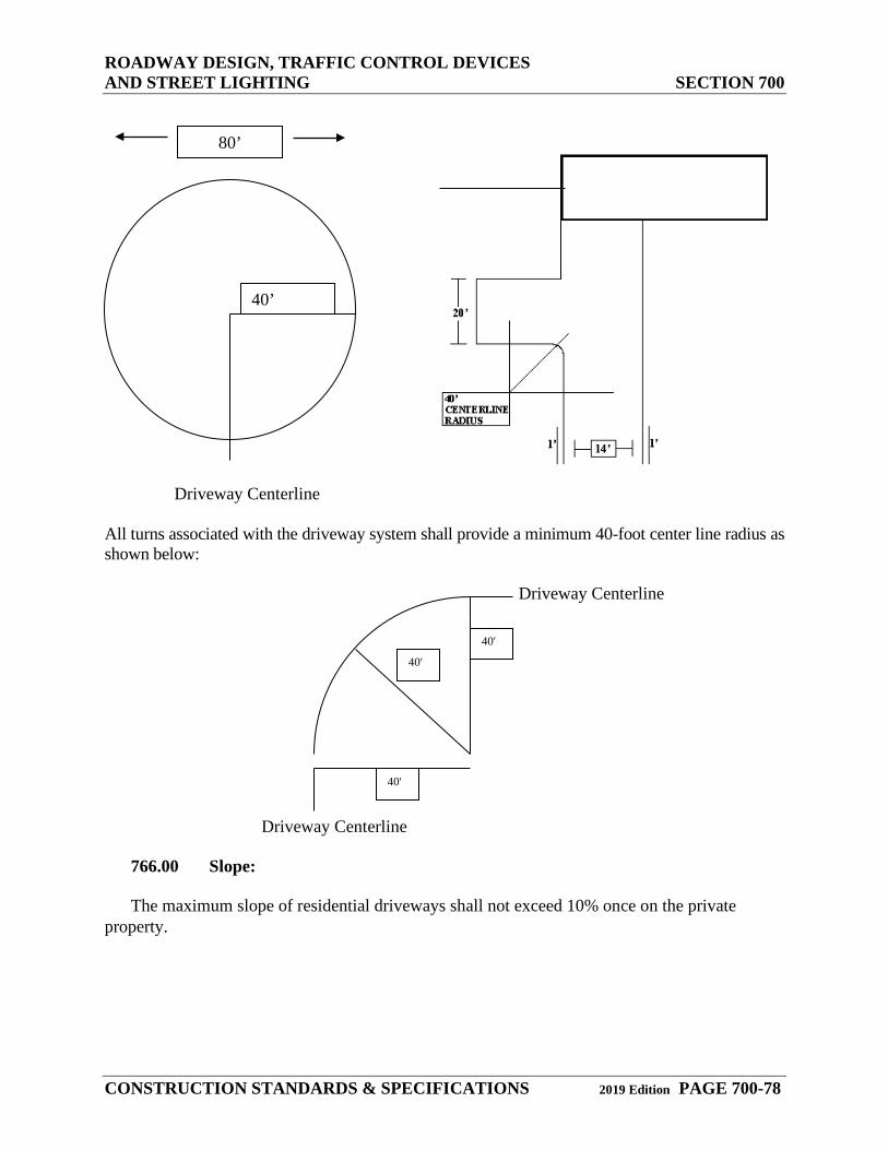
ROADWAY DESIGN, TRAFFIC CONTROL DEVICES AND STREET LIGHTING SECTION 700
CONSTRUCTION STANDARDS & SPECIFICATIONS 2019 Edition PAGE 700-78
Driveway Centerline
All turns associated with the driveway system shall provide a minimum 40-foot center line radius as shown below: Driveway Centerline
Driveway Centerline
766.00 Slope: The maximum slope of residential driveways shall not exceed 10% once on the private property.
80’
40’
40'
40'
40'
ROADWAY DESIGN, TRAFFIC CONTROL DEVICES AND STREET LIGHTING SECTION 700
CONSTRUCTION STANDARDS & SPECIFICATIONS 2019 Edition PAGE 700-79
Exceptions: A: Houses equipped with an approved automatic sprinkler system installed and
maintained in accordance with NFPA 13D, Standard for the Installation of Sprinkler Systems in Single-family dwellings.
B: When approved by the authority having jurisdiction.
Maximum slope of a driveway will be determined by the Fire District under whose jurisdiction the residence falls under.
767.00 Bridges and Water Crossings:
Bridges and other water crossing appliances shall be designed and constructed to handle the imposed loads of fire apparatus in all-weather situations. In many cases, bridges and crossings may require the approval stamp of a professional engineer.
Bridges and other water crossing structures will be designed and constructed to handle the imposed loads of fire apparatus in all-weather situations. In many cases, bridges and crossings will require the approval stamp of a professional engineer.
768.00 Livestock Crossings:
Livestock crossings and grates shall be designed and constructed to withstand the imposed loads of fire apparatus (up to 67,000 pounds depending on the jurisdiction)
Exceptions. A: When approved alternate means of access are provided around the grate, the
provisions of 2-8 may be modified.
Livestock crossings and grates will be designed and constructed to withstand the imposed loads of fire apparatus (up to 67,000 pounds depending on the jurisdiction) In many cases, livestock crossings will require the approval stamp of a professional engineer.
When approved by the Elbert County Road and Bridge Department and the Fire District, an alternate means of access around the grate can be used. (See Section 12.3.6.3.1.2 of the Elbert County Roadway Design Construction Manual.)
769.00 Gates and Limited Access Appliances:
(See Section 12.3.6.9 of the Elbert County Roadway Design Construction Manual.) Private dwelling gates shall provide a minimum 14-foot unobstructed width and shall be operable without special knowledge or force.
Exception:
ROADWAY DESIGN, TRAFFIC CONTROL DEVICES AND STREET LIGHTING SECTION 700
CONSTRUCTION STANDARDS & SPECIFICATIONS 2019 Edition PAGE 700-80
A. Gates that utilize an approved access control device to ensure immediate access to the dwelling. Device information can be obtained by contacting the appropriate fire protection agency.
Gates shall be located a minimum of 30 feet off the roadway to ensure a safe and unobstructed traffic flow during emergency response.
Private dwelling gates will provide a minimum 16-foot unobstructed width and will be operable without special knowledge or force.
Gates that utilize a control device must be approved by the Fire District. All gates shall open inward, outward opening gates are prohibited.
Gates will be located a minimum 30’ off the roadway shoulder to ensure a safe and unobstructed traffic flow during emergency response.
770.00 COMMERCIAL DRIVEWAY REQUIREMENTS
771.00 Width:
Driveways shall provide for a minimum of 40 foot turning radius at county road/private road.
32 feet from property line to edge of county road/private road.
Road base must be a CDOT Class VI material.
772.00 Surface:
All roadbase material shall be a minimum 6 inches thick and shall provide an all-weather driving surface capable of handling 85,000 lbs.
773.00 Approach:
All driveways must approach the roadway at a 70-90-degree angle perpendicular to the intersecting roadway.
774.00 Culverts
The minimum type is corrugated metal pipe. Depending on engineering recommendations reinforced concrete pipe might be required.
Culvert diameter-dependent on-site plan
Culvert length-minimum length is 44 feet plus flared ends
ROADWAY DESIGN, TRAFFIC CONTROL DEVICES AND STREET LIGHTING SECTION 700
CONSTRUCTION STANDARDS & SPECIFICATIONS 2019 Edition PAGE 700-81
775.00 Paved surfaces
All driveways that meet or join paved roads must be paved with asphalt. Concrete may be used on a case by case basis.
Pavement thickness must be capable of handling 85,000 lbs.
Drive must be paved from the property line to the edge of the paved portion of the county road/private road. This is the minimum requirement.
Adequate sight distance for the driveway must meet County code.
Drive must have a 1% fallback measured from the centerline ditch to the property line. All major Commercial Developments shall be required to submit a Site Plan for access
approval. 780.00 CULVERTS
A minimum 18" diameter corrugated metal pipe (CMP) culvert or equivalent volume, shall be required at the established ditch flow line. A sketch plan of the installation must be submitted with the access permit application.