Embed Size (px)
Citation preview

Adopted December 13, 2016 600 - i
SECTION 600
TRANSPORTATION SYSTEMS
Page
600.01 DEFINITIONS 600-1
601.00 TRANSPORTATION SYSTEMS - GENERAL POLICY
AND REQUIREMENTS
601.01 Street Design .............................................................................. 600-2
601.02 Functional Classification of Streets ........................................ 600-3
601.03 Street Dedication ....................................................................... 600-5
601.04 Street Access ............................................................................. 600-5
601.05 Street ......................................................................................... 600-7
601.06 Street Extensions to the Property Line ...................................... 600-7
601.07 Service Drives .......................................................................... 600-8
601.08 Street Curb and Gutter .............................................................. 600-8
601.09 Street Lights ............................................................................. 600-9
602.00 TRANSPORTATION SYSTEMS - PLANNING AND DESIGN
602.01 Traffic Impact Analysis (TIA) .................................................. 600-09
602.02 Transportation Demand Management (TDM) ......................... 600-10
602.02.1 Purpose ...................................................................................... 600-10
602.02.2 When a TDM Plan is Required ................................................. 600-10
602.03 Trip Generation Standards ........................................................ 600-11
602.04 Design Speed Standards ........................................................... 600-11
602.05 Sight Distance Standards ........................................................... 600-11
602.06 Median Crossovers..................................................................... 600-12
602.07 Street Intersections .................................................................... 600-12
602.08 Street Cul-de-sacs .................................................................... 600-14
602.09 Street Grade and Layout ........................................................... 600-15
602.10 Street Pavement Design ............................................................ 600-16
602.11 Alternate Pavement Design ....................................................... 600-16
602.12 Paved Ditches, Underdrains and Guardrails .............................. 600-17
602.13 Street Lights .............................................................................. 600-18
602.14 Privately Maintained Travelways and Parking Areas ............... 600-18
602.15 Privately Maintained Travelway Pavement Design ................. 600-20
602.16 Pipestem Driveways and Alleyways ......................................... 600-20
602.16.1 Pipestem Driveways ................................................................. 600-20
602.16.2 Alleyways in Planned Districts .................................................. 600-23
602.17 Common Driveways for Two Lots .......................................... 600-24
602.18 Sidewalks/Shared Use Paths ...................................................... 600-24
602.19 Sidewalk/Shared Use Path Maintenance .................................. 600-25

Adopted December 13, 2016 600 - ii
602.20 Trail/Shared Use Path Safety Considerations ........................... 600-25
602.21 Trail/Shared Use Path Easements ............................................ 600-26
602.22 Trail/Shared Use Path Grade and Drainage .............................. 600-26
602.23 Trail/Shared Use Path Bridges ................................................... 600-27
602.24 Trail/Shared Use Path Steps ..................................................... 600-27
602.25 Street Planting .......................................................................... 600-27
603.00 TRANSPORTATION SYSTEMS - SUBMISSION REQUIREMENTS
603.01 Traffic Impact Analysis (TIA) .................................................. 600-28
603.02 Plans ........................................................................................... 600-28
603.03 Topographic Information and Grading Plans for Streets ......... 600-28
603.04 Street Station Points and Centerline Curve Information ........... 600-29
603.05 Street Sight Distances ............................................................... 600-29
603.06 Building Restriction Line Profiles for Streets ........................... 600-29
603.07 Street Centerline Profiles .......................................................... 600-30
603.08 Street Grade Lines and Cross Sections .................................... 600-30
603.09 Street Cul-de-sacs ..................................................................... 600-31
603.10 Street Pavement ....................................................................... 600-31
603.11 Street Curb and Gutter ............................................................. 600-31
603.12 Street Landings ......................................................................... 600-31
603.13 Street Entrances ....................................................................... 600-31
603.14 Street Ditches ............................................................................ 600-32
603.15 Guardrails ................................................................................. 600-32
603.16 Storm Sewer and Utility Lines in Relation to Streets ................ 600-32
603.17 Stream Profiles in Relation to Streets ....................................... 600-33
603.18 Street Slope Easements ............................................................ 600-33
603.19 Erosion Control for Streets ...................................................... 600-33
603.20 Street Lighting Plan .................................................................. 600-33
603.21 Street Barricades ....................................................................... 600-34
603.22 Street Names ............................................................................ 600-34
603.23 Street Names in Relation to Street Type .................................. 600-35
603.24 Street Addresses ........................................................................ 600-36
603.25 Plats .......................................................................................... 600-36
604.00 TRANSPORTATION SYSTEMS - CONSTRUCTION STANDARDS
604.01 Street Construction ................................................................... 600-37
604.02 Street Curb and Gutter/Sidewalks ............................................. 600-38
604.03 Paved Ditches, Guardrails and Retaining Walls and Noise
Abatement Facilities ................................................................ 600-38
604.04 Street Signs ............................................................................... 600-39
604.05 Street Traffic Control Signs ...................................................... 600-40
604.06 Street Name Signs ..................................................................... 600-40
604.07 Privately Maintained Travelways and Streets ........................... 600-42
604.08 Privately Maintained Travelway Signs ..................................... 600-42

Adopted December 13, 2016 600 - iii
604.09 Traffic Signal – VDOT and PWC Pre-Emption Systems ......... 600-42
610.00 TRANSPORTATION SYSTEMS - OFF-STREET PARKING
610.01 General Requirements for Off-Street Parking ......................... 600-42
610.02 Parking and Loading Spaces Required ..................................... 600-44
610.03 Parking Credit Allowance ........................................................ 600-44
610.04 Parking Deferrals ...................................................................... 600-45
610.05 Setbacks .................................................................................... 600-45
610.06 Layout and Design .................................................................... 600-45
610.07 Off-Street Stacking Spaces ....................................................... 600-48
610.08 Accessible Parking ................................................................... 600-48
610.09 Layout and Design for Motor Vehicle Fuel Sales and
Convenience Food Stores ........................................................ 600-49
610.10 Parking Lot Landscaping .......................................................... 600-49
610.11 Outdoor/Roadway Lighting ...................................................... 600-49
620.00 TRANSPORTATION SYSTEMS - TRAFFIC IMPACT ANALYSIS
620.01 Title and Purpose ...................................................................... 600-49
620.02 Administration .......................................................................... 600-50
620.03 Study Area ............................................................................... 600-50
620.04 Design Year .............................................................................. 600-51
620.05 Traffic Data Requirements and Existing Conditions ................ 600-51
620.06 Trip Generation ......................................................................... 600-52
620.07 Future Traffic Conditions ........................................................ 600-53
620.08 Trip Distribution and Assignment ........................................... 600-53
620.09 Analysis .................................................................................... 600-54
620.10 Recommendations ..................................................................... 600-55
630.00 TRANSPORTATION DEMAND MANAGEMENT (TDM)
630.01 What to Include in a TDM ........................................................ 600-55
630.02 Administration .......................................................................... 600-57
640.00 TRANSPORTATION CONSTRUCTION AND INSPECTIONS
640.01 Comprehensive Inspection Program ......................................... 600-59
640.02 Pre-Construction ....................................................................... 600-59
640.03 Street Construction Inspection .................................................. 600-60
640.04 Special Agreements .................................................................. 600-60
640.05 Street Acceptance ...................................................................... 600-61
Adopted December 13, 2016 600 - iv
TABLES
Table 6-1 Trip Generation ......................................................................... 600-62
Table 6-2 Design Speed for New Streets .................................................. 600-62
Table 6-3 Design Speed for Existing Streets ............................................ 600-62
Table 6-4 Stopping Sight Distance ........................................................... 600-63
Table 6-5 Intersection Sight Distance ....................................................... 600-63
Table 6-6 Crossover Spacing ................................................................... 600-64
Table 6-7 Minimum Turn Lane Requirements .......................................... 600-64
Table 6-8 Required Loading and Off-street Parking Spaces .................... 600-65
Table 6-9 Pump Island Setback ................................................................ 600-73
Table 6-10 Minimum Off-street Parking Area Dimensions ........................ 600-74
Table 6-11 Parallel Parking and Aisle Dimensions .................................... 600-74
Table 6-12 TIA Guidelines for Study Design Year Horizons .................... 600-75
650.00 TRANSPORTATION SYSTEMS - DETAILS
650.01 Standard Pavement Design ...................................................... SPD-1
650.02 Residential Local Streets Without Curb and Gutter
(Fixed Traffic) ............................................................................ RL-1
650.03 Residential Minor Collector Streets Without Curb and Gutter . RM-1
650.04 Residential Local Streets With Curb and Gutter
(Fixed Traffic) .......................................................................... RL-2
650.05 Residential Minor Collector Streets With Curb and Gutter ..... RM-2
650.06 Travelways for Industrial, Institutional, Office, Commercial,
Single-family Attached and Multifamily Developments .......... TS-1
650.07 Condominium, Mobile Home and Apartment
Streets With No Residential Frontage ....................................... MF-1
650.08 Commercial and Industrial Streets With Curb and Gutter ....... CI-1
650.09 Major Collector Streets as Designated by the Comprehensive
Plan (4-lane Divided With Curb and Gutter) ............................. MC-1
650.10 Major Collector/ Minor Arterial Streets as Designated by the
Comprehensive Plan (4-lane Divided Without Curb & Gutter) MC-2/
.................................................................................................... MA-2
650.11 Minor Arterial Streets as Designated by the Comprehensive
Plan (6-lane Divided With Curb and Gutter) ............................ MA-1
650.12 Principal Arterial /Parkways as Designated by the
Comprehensive Plan (8-lane Divided With Curb and Gutter) .. PA-1
650.13 Principal Arterial /Parkways as Designated by the
Comprehensive Plan (4-lane Divided Initially) ....................... PA-2
650.14 Through Boulevard in Urban Centers ........................................ UTB-1
650.15 Boulevard in Urban Centers ...................................................... UB-1
650.16 Avenue and Street in Urban Centers .......................................... UAS-1
650.17 Private Residential Street in Urban Centers ............................... UPS-1
650.18 Private Alley in Urban Centers ................................................. UA-1

Adopted December 13, 2016 600 - v
650.19 Street Tree Planting for Urban Centers ...................................... UST-1
650.20 Curb Extension Layout Design ................................................ CSL-1
650.21 Curb and Gutter for Service Drives .......................................... SD-1
650.22 Standard Cul-de-sac With Curb, Gutter and Sidewalk ............. CS-1
650.23 Offset (Left) Cul-de-sac With Curb, Gutter and Sidewalk ....... CS-2
650.24 Offset (Right) Cul-de-sac with Curb, Gutter and Sidewalk ..... CS-3
650.25 Offset Cul-de-sac With Curb, Gutter and Sidewalk (With
Center Island) ............................................................................ CCI-1
650.26 Standard Cul-de-sac With Curb, Gutter and Sidewalk
(With Center Island) ............................................................... CCI-2
650.27 Standard Cul-de-sac on Ditch Section Street ............................ DS-1
650.28 Offset (Left) Cul-de-sac on Ditch Section Street ...................... DS-2
650.29 Offset (Right) Cul-de-sac on Ditch Section Street ................... DS-3
650.30 Travelway Turnaround Standards ............................................. TT-1
650.31 Travelway Turnaround for Emergency Vehicles and
Service Trucks ......................................................................... TT-2
650.32 Pipestem Entrance Design With Curb and Gutter .................... PP-1
650.33 Typical Acceptable Pipestem Lot Layouts
(Double Stacking) ..................................................................... PP-2
650.34 Intersection Landing Requirements .......................................... IL-1
650.35 Intersection Sight Distance Requirements ............................... ISD-1
650.36 Bicycle Trail/Shared Use Path Standards for VDOT
Maintenance .............................................................................. BT-1
650.37 Asphalt Park Trail (Not Eligible for VDOT Maintenance) ...... PT-1
650.38 Full Bench Cut Trail (Not Eligible for VDOT Maintenance) ... CT-1
650.39 Hiking Trail (Not Eligible for VDOT Maintenance) ................ HT-1
650.40 Equestrian Trail (Not Eligible for VDOT Maintenance) .......... ET-1
650.41 Standard Sidewalk With Underdrains ...................................... SS-1
650.42 Alternative Entrance With Curb and Gutter ............................. DE-1
650.43 Driveway Entrance With Curb and Gutter
(Single family Detached) ........................................................ DE-2
650.44 Driveway Entrance With Curb and Gutter
(Single family Attached with Garage) ..................................... DE-3
650.45 Driveway Entrance With Ditch Section ................................... DE-4
650.46 Curb Cut Ramp ......................................................................... CCR-1
650.47 Standard Road Edge Delineators .............................................. ED-1
650.48 Special Road Edge Delineators ................................................ ED-2
650.49 Standard Type III Traffic Barricade ........................................ TB-1
650.50 Shoulder Stabilization at Intersections ...................................... SI-1
650.51 Mailbox Location ...................................................................... MBL-1
650.52 Street Name Sign Standard ....................................................... SNS-1
650.53 Street Name Signs on Tapered Aluminum Signal Poles .......... SNS-2
650.54 Thru Street Sign Standard ........................................................ TSS-1
650.55 Dead End/No Outlet Street Sign Standard ............................... DES-1
650.56 Private Street Sign Standard ..................................................... PSS-1
650.57 Accessible Parking Space Standard .......................................... HP-1
Adopted December 13, 2016 600 - vi
650.58 Accessible Parking Standard for Two Adjacent
Parking Spaces ......................................................................... HP-2
650.59 Electric Vehicle (EV) Charging Station .................................... EV-1
650.60 Range Address Sign for Pipestems ........................................... RAS-1
650.61 Street Light Installation ............................................................. SLI-1
650.62 Private Travelway Speed Humps .............................................. PTS-1
650.63 Asphalt Pavement Widening for Widening Subject to Traffic .. APW-1
650.64 State Maintenance Road Sign ................................................... SMS-1

Adopted December 13, 2016 600 - 1
SECTION 600
TRANSPORTATION SYSTEMS
600.01 Definitions:
A. AASHTO: The American Association of State Highways and Transportation Officials.
B. Alleyway: a privately maintained travelway primarily designed to provide a secondary access
to the side or rear of properties whose primary frontage is on another street. Alleys may be
allowed on single family residential, multi family, townhouse/single family attached, and
commercial uses of town center developments.
C. Bridge: A structure erected over a watercourse, depression, or obstacle (Webster’s Collegiate
Dictionary). As distinguished from a culvert, it is a large structure spanning a watercourse, the
bed of which is left comparatively undisturbed. The opening width is generally large compared
to the length (in the direction of flow). The structure generally consists of a deck or
superstructure supported on two or more abutments or piers.
D. Care Facilities: Hospitals, adult and/or child day care centers, nursing convalescent homes
and their buildings and associated parking.
E. Channelization: The design of a street intersection which separates conflicting traffic
movements into definite paths of travel by the application of pavement markings, raised median
or other appropriate means to facilitate the safe and orderly movement of both vehicles and
pedestrians.
F. Commercial/Retail: Buildings with uses that are primarily retail, or retail-related, including
shopping centers, motor vehicle fuel sales, etc.
G. Institutional uses: Churches, cemeteries, rescue squads, fire departments, police departments,
libraries, school (public and private) and their related building and parking lots.
H. MUTCD: The Manual of Uniform Traffic Control Devices.
I. Office: Buildings with primarily administrative activities, including financial institutions.
J. Pipestem driveway: Driveway or shared driveway servicing up to five (5) pipestem lots.
K. Pipestem lot: A lot in a cluster development for which the minimum frontage for the zoning
district in which it is located is not required to be met.
L. Street, Public: A thoroughfare (street, drive, avenue, boulevard, etc.) which has been or is
intended to be dedicated for public use, and which has been accepted or is intended to be
accepted into the State system.

Adopted December 13, 2016 600 - 2
M. Street, Private: Where permitted, a privately maintained thoroughfare designed to provide
access to private property.
N. Traffic study: A study conducted to assess the impact of traffic generated by a new use or
change in use on existing or future road network, and to obtain the required information in
evaluating any potential road network improvements.
O. Travelways: A directional path primarily used for vehicular movement, that is designed to
provide access to parking bays and/or adjacent parking spaces and to and from privately
maintained properties, commercial, industrial, single family attached and multifamily
developments, whether or not in an easement or built to design standards. They are considered
as private streets or roadways and are not intended for acceptance into State or County
maintained roadway systems.
P. Use group: The classification of a building or structure based on the purpose for which it is
used, as listed in the Virginia Uniform Statewide Building Code.
Q. VDOT: The Virginia Department of Transportation.
R. vpd: Vehicles per day
601.00 TRANSPORTATION SYSTEMS - GENERAL POLICY AND REQUIREMENTS
601.01 Street Design:
A. The provisions of this section shall apply to all street design and construction in the County.
Where no specific roadway construction, design standard, or specification is set forth in this
manual, the provisions of the Virginia Department of Transportation (VDOT) Road and Bridge
Standards, Secondary Street Acceptance Requirements, Minimum Standards for Entrances to
State Highways, Road Design Manual - Appendix A, A Policy on Geometric Design of Highway
and Streets Manual Current Edition of American Association of State Highway and
Transportation Officials (AASHTO) and the Virginia supplement to the Manual of Uniform
Traffic Control Devices (MUTCD) shall be used.
B. Northern Virginia has been designated as an urban area by VDOT subdivision standards. All
streets shall be designed as set forth in this manual or by VDOT standards, whichever is more
stringent.
C. The arrangement of major streets in a development shall provide for their proper continuation
with developed adjoining properties, and for their proper extension into undeveloped adjoining
properties. The proper interparcel connecting arrangement shall be accomplished by the use of
stub streets and temporary cul-de-sacs, etc., which is intended to provide and maintain access for
basic public services, to allow movement of vehicular, bicycle, and pedestrian traffic, and to
provide a corridor for public utilities. If a waiver is requested, it is the developer’s responsibility
to provide a detailed narrative why an interparcel connection between developments could not be

Adopted December 13, 2016 600 - 3
achieved or provided or why such connection would not be beneficial to the County as required
by this section.
D. Interparcel connecting streets shall be designed in consideration of the anticipated future
traffic from undeveloped adjacent tracts based on the land use classifications of the Long Range
Future Land Use Plan Map of the Comprehensive Plan.
E. The Thoroughfare Plan of the Comprehensive Plan indicates the necessity for major collector
and arterial streets. The design and provision for the continuation of these streets shall be
addressed in the design of all developments.
F. The street network proposed by a development shall be designed to provide an orderly access
progression from local streets, to collector streets, to arterial streets. The planning and/or design
of intersections to arterial or higher category roadways, shall only be allowed with the same or
next category of street (major collector) unless it can be properly demonstrated that existing
and/or projected traffic counts do not require a major collector or arterial category for the
connecting road and no other alternative means of access is deemed feasible by the Director of
Transportation.
G. When interparcel connections are made, residential local streets shall be laid out to
discourage cut-through movements of vehicles, and to minimize or avoid four-way intersections.
H. Where interparcel connections are planned and required in developments where they are
appropriately essential, traffic calming devices such as multi-way stop signs, roundabouts,
choker islands, chicanes, etc. shall be provided as necessary and as required by the Director of
Transportation.
601.02 Functional Classification of Streets: Functional classification is the process by which
streets and highways are grouped together into systems according to the character of service they
provide or are intended to provide. The following types of systems shall be utilized as guidelines
to describe functional classifications within a street network, and shall not be utilized for the
design or cross section of specific streets. Street design shall be based on traffic generation,
existing and projected future traffic, adequate levels of service, and the Thoroughfare Plan of the
Comprehensive Plan.
A. Local Street: A local street represents the lowest category of the functional classification
system. Its sole function is to provide direct access to individual abutting parcels. Its traffic is
local in nature and extent, rather than intracounty, intercounty, or regional. Generally, traffic
volume should not exceed one thousand (1,000) vehicles per day (vpd).
B. Minor Collector Street: A minor collector street is designed primarily to serve the collection
function for a group of local streets. Additionally, its purpose is to provide direct access to
individual abutting parcels. It is designed to serve internal traffic movements within an area of
the County, and connect with the arterial system. It is not meant to handle long through trips.
Generally, traffic volume should range from one thousand one (1,001) vehicles per day (vpd) to
seven thousand (7,000) vehicles per day (vpd).

Adopted December 13, 2016 600 - 4
C. Major Collector Street: A major collector street has a primary function to provide intra-
neighborhood linkages and aggregate traffic, carrying it to the arterial system. It may also
penetrate a neighborhood, distributing trips to ultimate destinations and, in rare instances,
provide direct access to individual abutting parcels. Generally, traffic volume should range from
seven thousand one (7,001) vehicles per day (vpd) to fifteen thousand (15,000) vehicles per day
(vpd). This facility may carry local bus routes.
D. Arterial Street: An arterial street is designed to convey major movements of traffic
within or through the County. It interconnects the principal traffic generators within the County
and, in extremely rare instances, provides direct access to individual abutting parcels. There are
three (3) types of arterial classifications:
1. Minor Arterial: A street designed for intracounty circulation and designation of
neighborhood boundaries. It generally does not penetrate identifiable neighborhoods.
Access to neighboring development is achieved by good design and the appropriate
intersection spacing established in this section. Generally, traffic volume exceeds fifteen
thousand (15,000) vehicles per day (vpd). The facility may carry local bus routes.
2. Parkway: A street designed primarily for through traffic and intracounty movement. On
a parkway facility, service to the abutting land is subordinate to the provision of travel
service to major traffic movements. Access to abutting land is achieved at designated
intersections, rather than curb cuts, travelways and entrances. This facility is designed as a
scenic urban linear park containing a wide grass median with landscape plantings and/or
woodland conservation areas along each side. The landscape design is intended to be
consistent along its route to define and enhance the visual integrity of the roadway. The
facility also includes a sidewalk/shared use path for non-motorized traffic. Generally, traffic
volume exceeds fifteen thousand (15,000) vehicles per day (vpd).
3. Principal Arterial: A street designed primarily for through traffic and intra and
intercounty movement. On the principal arterial system, service to the abutting land is
subordinate to the provision of travel service to major traffic movements. Access to the
abutting land is minimized and is consolidated into service roads, shared entrances and
appropriate designated intersections. Almost all fully and partially controlled access
facilities are part of this functional class. Principal arterials also include a sidewalk/shared
use path for non-motorized traffic. Generally, traffic volume exceeds fifteen thousand
(15,000) vehicles per day (vpd). The facility may carry local bus routes.
E: Urban Street: Urban streets are streets that are designed to create safe movement for all users
including transit, motor vehicles, bicycles, and pedestrians within urban centers of the County.
All urban streets in urban centers shall be designed to accommodate the needs of users who want
to access or pass through the community, neighborhood, surroundings or areas planned as urban
centers. Urban centers refer to centers of commerce, centers of community, and urban mixed use
(UMU) areas as shown on the Comprehensive Plan Long Range Land Use Map. Urban centers
also refer to areas considered as a Town Center with Special Use Permit or are zoned Village
(V). Typical elements that may make up an urban street include sidewalks, bicycle lanes, on-
street parking areas, shared-use paths, transit stops, and pedestrian facilities including
crosswalks, median islands, accessible access/ramps, and curb extensions all integrated to allow

Adopted December 13, 2016 600 - 5
easier and safe access balancing safety and convenience for everyone using the street. Any
element of the urban street standards may be waived by the Director of Transportation with
reasonable and acceptable justifications.
1. Through Boulevard: A Through Boulevard is the street type of highest multimodal
capacity. It has higher speeds, medians, and street trees. It is intended to move traffic
at a high level of service in urban centers.
2. Boulevard: A Boulevard has the highest density of destinations, activity, and mix of
modes. Because of the close proximity of destinations, pedestrians and street activity
are common. It is intended to have on-road bicyclists and pedestrian crossings;
therefore traffic should move at a lower speed than on a Through Boulevard.
3. Avenue: An Avenue serves to connect Boulevards and Streets to Through
Boulevards. It provides access to businesses and residential areas as a primary
function.
4. Street: A Street connects to Avenues, Boulevards, or Through Boulevards and is
intended for more residential urban areas with lower traffic volumes than the Avenue.
5. Private Side Street: A Private Side Street is intended for urban residential areas with
on street parking and choker islands for landscaping. These streets will not be
maintained by VDOT.
6. Private Alley: A Private Alley is intended to serve the rear of properties providing
access to parking and service areas as well as to provide an easement for utilities.
Private Alleys will not be maintained by VDOT.
601.03 Street Dedication: When a development abuts one side of a state maintained
street(s),the developer shall be responsible for any right-of-way dedication, grading, surfacing,
and drainage along such street(s) as may be deemed necessary by the Director of Transportation
or VDOT and, to the extent commensurate with the additional traffic generated, to provide a safe
entrance into the development. The development should also address the dedication of sufficient
right-of-way and the construction of a half-section improvement of the street(s) for its entire
frontage, to conform to the design standard for that street(s) as shown in the Thoroughfare Plan
of the Comprehensive Plan, County approved functional plan, six-year secondary road plan as
approved by the Board of County Supervisors, centerline studies, engineering plans, and the
appropriate standards of this manual. The area dedicated for future roadway improvements may
be used, provided it is not for the purpose of satisfying minimum requirements of the DCSM or
Zoning Ordinance (i.e., parking storage, etc.). The placement of utilities within the dedicated
area will be allowed when they are consistent with the ultimate roadway construction. If the
dedicated area is used for any other purpose other than roadway construction, the developer shall
escrow funds for the removal of any improvements not consistent with the planned roadway
construction.
601.04 Street Access:
A. When the traffic generated from an entire development is projected to exceed two thousand
five hundred (2,500) vehicles per day (vpd), the development shall access an existing state street
in two locations. If approved by the Director of Transportation, one of the required connections
may be made to a street constructed to state standards to be included in the State street system.

Adopted December 13, 2016 600 - 6
A VDOT permit shall be required prior to any construction within the state maintained
right-of-way.
B. In situations where two (2) access points in accordance with the above cannot be physically
made (due to restrictions in topography or sight distance, or due to limitations in state street
frontage), a single connection may be allowed where specifically approved by the Director of
Transportation, subject to the following conditions:
1. The single access shall be of a four (4) lane divided standard, extending at least three
hundred (300) feet into the development for the first two thousand five hundred (2,500)
vehicles per day (vpd) generated. For every additional five hundred (500) vehicle trips
generated, or portion thereof, the four (4) lane divided street standard shall be extended an
additional one hundred (100) feet.
2. Private entrances shall not access a proposed four (4) lane divided street when that street
is designed in accordance with Section 601.04B(1). Internal streets and travelways in a
development shall access an arterial street where a crossover is permitted.
C. All single-family detached dwelling lots, unless otherwise specified in the Zoning Ordinance,
shall have frontage on and access to existing state maintained public streets or streets approved
and bonded to be constructed to a standard acceptable for addition to the State street system. The
amount of frontage shall be established in accordance with the regulations for the zoning district,
as provisioned in the Zoning Ordinance.
D. Commercial, institutional, and industrial lots may be approved for recording without public
street frontage, provided that lots have an access easement which meets the approval of the
Director of Transportation. To assure maintenance of the access easement, an association of
owners must be established prior to the approval of any plats or plans. Improvements within the
access easement must be sufficient to accommodate the type and volume of traffic anticipated
and constructed to the standards satisfactory to the Director of Transportation.
E. Single-family attached, multifamily, mobile home, commercial, and industrial development
shall have access to a state maintained street. This access may be via private travelways,
provided they meet the appropriate design standards in accordance with Details 650.06, 650.07,
and 650.08 of this manual. An association must be established for the ownership and perpetual
maintenance of travelways in a development. Travelways serving residential development shall
not carry greater than one thousand (1,000) vehicles per day (vpd).
F. Travelways in single-family attached and multifamily developments, where the design traffic
count exceeds one thousand (1,000) vehicles per day (vpd) shall be designed and constructed in
accordance with Detail 650.07 of this manual. These streets do not provide on-street parking and
are to be utilized only in developments where there is adequate off-street parking in separate
parking bays, and no individual unit fronts directly on the street.
G. In a residential mobile home (RMH) development, streets with projected vehicle counts
greater than four hundred twenty (420) vehicles per day (vpd) shall be designed and constructed
to a standard acceptable for incorporation into the State street system. All streets in any RMH
Adopted December 13, 2016 600 - 7
shall be named and signed accordingly to include directional signs to the addresses as well as the
units displaying legible address lettering. In addition, all streets shall have appropriate traffic
control signs according to the MUTCD.
H. Privately-maintained travelways shall be platted such that all lot owners are assured perpetual
right-of-access to a state maintained street. When permitted by the Zoning Ordinance,
single-family lots approved for suburban cluster standards may be platted with frontage and
access consisting of a pipestem driveway. In such cases, the development shall conform to the
requirements for pipestem driveways in accordance with Section 602.16.1 of this manual.
I. In commercial, institutional and industrial lots or developments, adequate interparcel
travelways shall be required to provide perpetual interparcel access for the movement of
vehicles. An adequate easement shall be provided for the interparcel access. The recorded plat
shall note the perpetual interparcel access as "privately owned and privately maintained by the
lot owner(s)."
601.05 Street Intersections:
A. Existing and proposed crossovers planned or approved by the Director of Transportation and
VDOT shall serve as the intersections for all development along existing and future divided
highways.
B. The number of intersections of local streets with collector or arterial streets shall be held to a
minimum to avoid hazard, delay, and preserve their integrity, and shall be coordinated with the
crossover locations planned or approved by the Director of Transportation and VDOT for
existing and future divided highways.
601.06 Street Extensions to the Property Line:
A. All streets shall be constructed to the property boundary with any adjoining properties if
eligible to be accepted into the state secondary system, and shall terminate with an on-site
temporary turnaround. However, off-site temporary turnarounds may be allowed if the
developer can obtain temporary turnaround easements from the adjacent property owners. If said
easements are provided, the developer shall escrow funds for the maintenance and removal of the
temporary turnaround. The construction of the temporary turnaround shall conform to the
pavement design of the street where they are located.
B. All planned interparcel connections shall be constructed to the subdivision or site boundary
limit with adjoining properties. If a temporary turnaround is required onsite, the right of way for
the turnaround shall be dedicated and all setback requirements referred from the right-of-way
line or the temporary turnaround easement whichever is more restrictive. In the event that the
interparcel connection is not constructed due to topographic or other physical constraints and/or
a change in the needs of the community, the temporary turn around shall be converted to a
permanent cul-de-sac acceptable to VDOT and the temporary easement converted to a permanent
right-of-way.

Adopted December 13, 2016 600 - 8
C. If the aforementioned construction of streets or interparcel connection to the property line
causes hardship to the developer, the Director of Transportation may allow the street
construction to stop a distance from the property line, to be determined at the time of site
development plan review.
D. The developer shall provide on-site temporary construction easements of sufficient width and
the right-of-way dedication to accommodate the permanent turnaround in the event such planned
interparcel connection will not be realized. The dedicated right-of-way area shall be vacated in
the event the connection is made.
E. Escrow shall be obtained for the following:
1. Maintenance and removal of the temporary turnaround.
2. Future completion of the street to the property line.
3. Grading and stabilization of disturbed areas within the easement.
601.07 Service Drives:
A. The reverse frontage concept, which allows internal public street frontage, is encouraged
such that no lot has direct ingress or egress along a major collector, minor arterial or primary
arterial street. If this is not feasible, common driveways and interparcel connectors shall be
utilized.
B. Development that cannot be served by common driveways and interparcel connectors shall
have a service drive fronting on major collectors, minor arterials or primary arterials to prevent
direct access to such streets. The service drive shall extend the full frontage of the development
along such streets, tie into neighboring development as an interparcel connector, and provide
limited access at the appropriate designated intersection. Service drive design and construction
shall be in accordance with Detail 650.21 of this manual.
601.08 Street Curb and Gutter:
A. Curb and gutter shall be provided within subdivisions requiring urban street sections. This
excludes rural residential zoning districts requiring a minimum lot size of one (1) acre and
greater and in low impact developments (LID).
B. Any required improvements to existing state maintained streets, necessitated by
development, shall provide curb and gutter and sidewalk/shared use paths if the adjoining
properties meet the requirements for curb and gutter.
C. On privately-maintained travelways, curb and gutter contiguous to a fire hydrant shall be
painted yellow, fifteen (15) feet to each side of the fire hydrant. This clear access area shall be
marked as fire lane.
Adopted December 13, 2016 600 - 9
601.09 Street Lights:
A. All roadway luminaires shall be installed, owned, and maintained by the supplying utility
company, upon approval of the County.
B. The developer shall pay for the cost of installation.
C. On public roadways, the County shall assume the operation and maintenance costs of the
luminaires once they are energized.
D. Bonding for the cost of installation of roadway luminaires is required.
E. Prior to the issuance of occupancy permits for lots in the vicinity of the roadway luminaires,
the luminaires shall be installed, as per the approved plans. If the installations are delayed due to
the utility company's scheduling procedures, a County-approved form, “Acknowledgement of
Street Lights Installation” must be completed by the contract purchasers. The completed form
and a paid receipt from the utility company shall be submitted to the site inspector before
occupancy is granted.
F. As part of the construction of all new developments, high pressure sodium vapor (HPSV)
roadway luminaires and related wiring must be installed by the servicing utility company in a
dedicated utility easement.
G. Estimates for both roadway luminaire(s) and main line installations must be requested by the
developer from the servicing utility company. Roadway luminaires and main line should be
installed simultaneously.
H. All roadway luminaire installations shall conform to VDOT specifications.
I. The utility company will inform the developer of any modifications that may require
compliance with current VDOT specifications.
J. The developer must submit a County-approved plan and bond sheet to the servicing utility
company with roadway luminaire locations.
K. Street lighting at the entrances of residential communities and commercial developments
shall be the cobra head type fixtures or the expressway/interstate type fixtures. Decorative, area,
or security lighting fixtures are acceptable as internal roadway lighting if the fixtures provide
Type III light distribution.
602.00 TRANSPORTATION SYSTEMS - PLANNING AND DESIGN
602.01 Traffic Impact Analysis (TIA):
A. If a previous TIA was submitted at the rezoning or special use permit review stage, and the
assumptions used in the TIA are consistent with the submitted site plan, no additional TIA will
Adopted December 13, 2016 600 - 10
be required. However, if a previous TIA was not submitted in conjunction with the proposed
development, a TIA shall be required for all developments, if the total generated additional trips
meet or exceed one (1) or more of the following thresholds:
1. One hundred (100) or more total site generated peak hour trips or 1,200 trips per day as
defined by the current edition of the Institute of Transportation Engineers (ITE) Trip
Generation Manual or by a trip generation study acceptable to the County.
2. Anticipated new trip generation that uses any reserve roadway capacity to a point which
changes the existing level of service on a roadway or each lane group at the intersection to
"D" or below, based on the highway capacity manual thresholds.
3. The study area contains a segment of roadway and/or intersection considered unsafe. A
location is considered unsafe when five (5) reportable accidents have occurred in the prior
twelve (12) month period, or if it is on the County's annual list of most hazardous locations,
provided by the Prince William County Police Department.
4. The Director of Transportation deems that it is prudent to require such assessment in the
plan review process.
A TIA shall be prepared and submitted in accordance with Section 620.00 of this manual.
602.02 Transportation Demand Management (TDM)
602.02.1 Purpose
The purpose of these requirements is to provide a clear, concise set of guidelines for the area to
be studied, the analysis and methodology to be employed, and recommendations to assess the
effectiveness of a development proposal’s Transportation Demand Management (TDM)
strategies in reducing congestion while promoting alternative forms of transportation on the
existing and future transportation network. In addition, they are designed to advise applicants
what constitutes a comprehensive acceptable TDM plan for development proposals.
602.02.2 When A TDM Plan Is Required:
A. A TDM plan is required if the development proposal consists of Mixed-Use urban/suburban
activity centers including a Neo-Traditional Development and/or Transit Oriented Development
and the applicant is requesting trip generation credits or reductions in conjunction with the
proposed development. These types of developments typically include higher intensities of land
use than normally anticipated by the zoning ordinance. The TDM plan shall identify and
mitigate the effects of these higher intensities.
B. A TDM plan shall be prepared and submitted in accordance with Section 630.00 of this
manual.

Adopted December 13, 2016 600 - 11
C. A Traffic Impact Analysis (TIA) shall be required in conjunction with the submission of a
TDM plan, either separately or as a part thereof. The TIA shall be prepared and submitted in
accordance with Section 620.00 of this manual.
D. Strategies identified in the TDM Plan shall be measurable, monitorable, and enforceable
through proffer.
E. Implementation of the TDM plan shall be designated in the plan.
602.03 Trip Generation Standards:
A. For residential development, the twenty-four (24) hour trip generation rate per dwelling unit
shall be utilized in accordance with Table 6-1.
B. For commercial, industrial, institutional, and other development, the rates shown in the
current edition of the Institute of Transportation Engineers’ Reference Book, “Trip Generation
Manual,” shall be utilized.
C. All projected average daily trips (ADT) or design traffic volumes should be shown at each
site entrance and roadway.
602.04 Design Speed Standards:
A. Design speeds are used to determine the geometric design of streets to accommodate safe
operation of vehicles to address sight distance requirements for all streets, travelways, access
points, and commercial entrances.
B. The minimum design speed for new streets shall be based on the projected average daily trips
(ADT) as shown in Table 6-2.
C. On existing streets, the design speed shall be determined by Table 6-3.
602.05 Sight Distance Standards:
A. Each new street shall be designed with horizontal and vertical curves meeting or
exceeding the minimum stopping sight distance outlined in Table 6-4, and the minimum
horizontal/intersection sight distance outlined in Table 6-5. Vertical curves shall have a
minimum length of one hundred (100) feet except on cul-de-sac roll outs and intersections
(Sec 650.34).
B. Sag vertical curves are required to provide not less than the sight distance shown in
Table 6-4.
C. Sight distance for sag vertical curves shall be calculated for all ranges of algebraic
difference in grade based on a headlight of two (2) feet and one degree upward divergence of the
headlight beams. For horizontal sight distances, the location of the driver's eye should be set
Adopted December 13, 2016 600 - 12
fourteen and a half (14.5) feet from the edge of outermost through lane of the roadway in
question, as shown and specified in Detail 650.35 of this manual. (approved 8-4-15)
D. Table 6-4 assumes an eye height of three (3) feet, six (6) inches and a height of object (2) two
feet.
E. Desirable sight distance values in Table 6-4 shall be used as the minimum values on all
streets which carry greater than seven thousand (7,000) vehicles per day (vpd).
F. The K value in Table 6-4 is a coefficient by which the algebraic difference in grade may be
multiplied to determine the length in feet of the vertical curve which will provide the minimum
sight distance. K value shall be used to provide the minimum sight distance.
G. Table 6-5 assumes an eye height of three (3) feet, six (6) inches and a height of object of
three (3) feet, six (6) inches.
H. The term "major street" in Table 6-5 refers to the street with the highest vehicles per day
(vpd) of the two (2) intersecting roads.
I. All existing VDOT maintained streets are considered major streets. For divided streets where
the median widths are greater than sixty (60) feet, each direction can be considered separately.
J. For more than four (4) lanes on a major street, or for large truck volumes on a minor street
with twenty percent (20%) to twenty-five percent (25%) of the average daily trips (ADT),
crossover or commercial entrance, use values in the latest edition of the "Policy on Geometric
Design of Highways and Streets" published by AASHTO.
K. After each street has been designed in accordance with the criteria above, each intersection
shall be checked for compliance with Table 6-5, and other intersection items such as standard
landings (Detail 650.34), channelization, etc. Each connection to existing streets shall be
checked to insure that the proper sight distances are achieved. The verification of these sight
distances should be done graphically, checking both the horizontal and vertical alignments.
602.06 Median Crossovers:
Minimum crossover spacing along a divided street shall be provided in accordance with Table
6-6 or if the street is a state maintained road, the spacing shall be in accordance with VDOT
Access Management Standards. The values for desirable distance between crossovers shown in
the table shall be utilized in the design of all streets which will carry greater than seven thousand
(7,000) vehicles per day (vpd).
602.07 Street Intersections:
A. Along arterial and major collector streets, the centerline separation of street intersections
within the same lot, parcel, or development shall follow the minimum distance between
crossovers as noted on Table 6-6 or if the street is a state maintained road, the spacing shall be in
accordance with VDOT Access Management Standards. Along minor collector streets, the

Adopted December 13, 2016 600 - 13
separation of accessing streets shall be three hundred (300) feet, unless proven to be undesirable
by an approved intersection study.
B. A distance of at least two hundred (200) feet shall be maintained between centerlines of local
street intersections.
C. All streets designed to carry traffic volume up to one thousand (1,000) vehicles per day (vpd)
shall intersect at right angles for a minimum tangent distance of one hundred (100) feet. The
tangent shall be measured from the face of curb or edge of pavement of the major street. For
streets designed to carry traffic volumes exceeding one thousand (1,000) vehicles per day (vpd),
a minimum tangent distance of two hundred (200) feet shall be required.
D. All shoulders of ditch type streets shall be paved at intersections in accordance with
Detail 650.50 of this manual.
E. Along roadways classified as Category VI and above, left and right turn lanes shall be
provided at all intersections, crossovers and/or entrances to developments. In addition, a
signalized dual left turn lane shall be provided where existing or projected turning volume counts
exceed three hundred (300) peak hour volumes (PHV) or design hourly volumes (DHV) or as
otherwise warranted.
F. A right turn lane and taper shall be required at any intersection approach on a roadway that
carries six thousand (6,000) or more vehicles per day (vpd).
G. All required standard deceleration or turn lanes and tapers shall be designed in accordance
with VDOT and AASHTO standards (see Table 6-7).
H. When deemed necessary by a traffic impact analysis, the Director of Transportation and
VDOT, a protected left turn lane shall be required at all street intersections where existing or
projected turning volume count on either street exceeds three thousand (3,000) vehicles per day
(vpd).
I. All curb returns shall have a minimum of thirty-five (35) feet radius for streets with curb and
gutter. However, on industrial intersections and streets without curb and gutter, a minimum fifty
(50) feet pavement return radius is required.
J. A standard CG-11 entrance shall be used for commercial and residential street intersections
and commercial entrances. A minimum curb return radius of twenty-five (25) feet shall be
required for commercial entrances. For street intersections, a thirty-five (35) foot curb return
radius shall be required. Other entrances may also be used for access to VDOT maintained
streets, with VDOT approval.
K. For all roadways classified as Category V and below, a distance of at least one hundred thirty
(130) feet shall be maintained between the ends and beginnings (PTCR and PCCR) of curb
returns of all commercial entrances (including single-family attached and multifamily). For all
roadways classified as Category VI and above, a distance of at least two hundred eighty (280)
feet shall be maintained between ends and beginnings (PTCR and PCCR) of curb returns of

Adopted December 13, 2016 600 - 14
commercial entrances (including entrances for single-family attached and multifamily). The
separation shall be the same between curb returns of an entrance and a roadway intersection.
L. Corner lots on street intersections, especially on curvilinear streets, shall be designed taking
into consideration intersection sight distance easement requirements. Intersection sight distance
easements should not occupy twenty-five percent (25%) or more of the total area of corner lots.
M. In general, driveway entrances on corner lots shall be located on minor streets or on the
street where a stop sign is posted and outside of sight distance easements.
N. All parking spaces on single-family attached, multifamily, commercial, institutional and
industrial developments should be designed such that their locations shall not obstruct the line of
sight as graphically shown on Detail 650.35.
O. In general, standard intersection landings shall be required for all streets with lower traffic
counts intersecting with streets carrying a higher volume of traffic in accordance with Detail
650.34 of this manual. The Director of Transportation or VDOT may approve alternative
intersection landing locations if future traffic movements and intersection conditions justify such
alternatives.
P. All entrances, except single-family detached driveways carrying less than one thousand
(1,000) vehicles per day (vpd), which access a public street, shall incorporate a two percent (2%)
landing for a minimum of twenty-five (25) feet from the existing edge of pavement.
Q. Entrances intended to carry over one thousand (1,000) vehicles per day (vpd) shall
incorporate the use of standard landings in accordance with Detail 650.34 of this manual.
R. Pedestrian accessible ramps in accordance with IIM-LD-55 shall be provided at all curbed
intersections, even when sidewalks and shared use paths are not present and shall be constructed
in accordance with VDOT standards, or ADAAG (American with Disability Act Accessibility
Guidelines) whichever is more restrictive.
S. A divided or channelized entrance will be provided for any entrance projected to carry 5,000
or more vehicles per day (vpd) in commercial, office or industrial developments. To enhance
development aesthetics, the median shall be landscaped. Entrances to residential subdivisions
that have medians shall also be landscaped.
T. All vehicles that are permitted to be parked or stored on residential properties on one (1) acre
or less shall be parked or stored only on areas that are improved. Such parking or storage areas
and similarly improved driveways shall not occupy more than thirty-five (35) percent of or seven
hundred and twenty (720) square feet of the minimum required front yard, whichever is greater.
In the case of pipestem lots, areas that are contained within the ingress and egress easement shall
not be included when calculating the coverage of the front yard by parking areas and driveways.
This maximum coverage requirement may be modified as a part of the consideration of a
modified dwelling unit type as indicated in the Zoning Ordinance.

Adopted December 13, 2016 600 - 15
602.08 Street Cul-de-sacs:
A. A cul-de-sac serving a residential development shall be designed to a length that will carry a
maximum of two hundred fifty (250) vehicles per day (vpd). The minimum pavement radius of
the cul-de-sac shall be forty-five (45) feet to either the face of the curb for urban streets or the
edge of the pavement for rural streets.
B. In the case where a residential cul-de-sac street intersects with a street presently
carrying, or projected to carry, greater than three thousand (3,000) vehicles per day (vpd),
the Director of Transportation may require a cul-de-sac radius of fifty (50) feet.
C. A cul-de-sac serving a commercial and industrial development shall be designed to a
maximum length of one thousand (1,000) feet. The minimum pavement radius of the cul-de-sac
shall be fifty (50) feet to the face of curb or edge of pavement.
D. For offset cul-de-sacs where the minimum required radius is fifty (50) feet, the layout of the
offset segment as shown in Details 650.23, 650.24, 650.28 and 650.29 should be considered in
the design.
E. On the circular segment of a public street cul-de-sac, only one entrance (CG-11) to a
single-family attached or multifamily development shall be permitted. The entrance shall
align at one hundred eighty (180) degrees with the centerline of the public street. If feasible,
three (3) entrances shall be allowed for commercial and industrial developments, provided their
centerlines align at ninety (90) degrees to each other.
602.09 Street Grade and Layout:
A. The minimum grade for streets with curb and gutter shall be five-tenths of a percent (0.5%).
The maximum street grade shall be as specified in the standards for each typical section. The
minimum grade for streets without curb and gutter shall be one percent (1%).
B. The maximum centerline grade at the cul-de-sac shall not exceed five percent (5%). Any
slope within the cul-de-sac pavement area shall not exceed five percent (5%). The cross slope of
the street leading to the cul-de-sac shall be a minimum of two percent (2%).
C. Design of reverse and compound centerline curves on roadways functionally classified as
Category VI and above, shall conform to minimum standard requirements of AASHTO-Policy
on Geometric Design of Highways and Streets.
D. Except as provided in Section 601.07 single family residential lots shall not access arterials
or major collector streets.
E. Loop or through roads shall have a standard typical cross section through their entire length
F. Lengths of horizontal centerline curves shall be in accordance with VDOT standards. The
minimum allowed arc length shall not be less than one hundred (100) feet.

Adopted December 13, 2016 600 - 16
G. Sharp centerline curves such as ninety (90) degree bends shall be avoided in the design of
roadways. If unavoidable, the centerline radius shall be increased to the extent possible to
achieve a roadway cross section that can accommodate two-way traffic of emergency vehicles
with consideration of parallel parking along it.
H. Along roadways classified as Category VI and above, the design of intersections on
horizontal curves should generally be avoided.
602.10 Street Pavement Design:
A. The required thickness of the subbase, base course, and top or surface course shall be in
accordance with the street standard in Detail 650.01 of this manual. CBR tests are required for
streets within single family detached, single family attached and condominium developments.
CBR tests are not required for private streets within multi-family, commercial, office, industrial
or institutional developments. Subbase and/or base thickness is based on a subgrade CBR value
of ten (10).
B. Final pavement design shall be determined after a CBR test is run to determine the true
support values of the various soils in the subgrade. A representative from the Department of
Transportation shall be present to verify the locations and minimum numbers of CBR tests
required at the time samples are acquired from the subgrade. With the prior approval of the
Director of Transportation, instead of a representative being present at the time of sample taking,
a licensed engineer may certify that the samples tested were acquired from the same locations as
indicated on the test results.
C. CBR test results shall be submitted in a form approved by the Director of Transportation and
certified by a licensed engineer.
D. CBR values less than ten (10) shall require redesign by the Vaswani method.
E. All pavement designs for streets with traffic volume exceeding one thousand (1,000) vehicles
per day (vpd) shall provide 21B, Type I aggregate as subbase or base material. This will also
necessitate consideration of underdrains in the design.
602.11 Alternate Pavement Design: When using alternate equivalent pavement design as a result of the CBR tests referenced in
Section 602.10 of this manual, the following minimum and maximum thickness of layers shall
apply:
A. Six (6) inches shall be the minimum thickness of the aggregate layer used as the base in a
one- or two-layer system.
B. Four (4) inches shall be the minimum thickness of the aggregate layer used as the subbase.
C. The minimum thickness of the bituminous concrete base layer for BM-25.0A shall be three
(3) inches.

Adopted December 13, 2016 600 - 17
D. One and one-half (1-1/2) inches shall be the minimum thickness of the bituminous concrete
surface lift (SM-9.5A or SM-9.5D) used on top of the bituminous concrete base layer (BM-
25.0A) or binder (IM-19.0A).
E. Two (2) inches shall be the minimum thickness of the bituminous concrete surface layer
(SM-9.5A or SM-9.5D) used on top of aggregate material (treated or untreated).
F. Six (6) inches shall be the minimum thickness of the stabilized soil layer (cement, lime, etc.).
G. Two (2) inches shall be the maximum thickness of the bituminous concrete surface
(SM-9.5A or SM-9.5D) for one lift.
H. For staged construction, two and one-half (2-1/2) inches shall be the maximum thickness of
the bituminous concrete surface (SM-9.5A or SM-9.5D). The thickness of each lift shall be of
one and one quarter (1-1/4) inches.
I. If staged construction is performed, a four (4) foot radius area, measured from the center of
the manhole cover around protruding utility manholes, shall be paved with leveling asphalt
concrete surface mix (SM-9.5A) to provide a relatively smooth riding surface. In addition, the
asphalt concrete paved peripheries shall be painted with twelve (12) inch wide white colored
paint acceptable to County inspectors. The maximum exposure limit for staged construction
shall be two (2) years, unless it is extended by the Director of Transportation.
J. One-half (1/2) inch integrals shall be utilized for aggregate materials (i.e., eight (8) inches or
eight and one-half (8-1/2) inches, but not eight and one quarter (8 1/4) inches
K. Eight (8) inches shall be the maximum thickness of the aggregate base or subbase material.
If eight (8) inches is exceeded, a bituminous material (BM-25.0A) shall be substituted.
L. When the bituminous concrete base is equal to or exceeds three (3) inches, the underlying
material shall be considered subbase.
M. As long as the total bituminous concrete thickness does not exceed four (4) inches, the first
eight (8) inches of the underlying material may use the thickness equivalency value for the base.
The remaining depth shall use the subbase value.
N. Six (6) inches shall be the maximum thickness of the aggregate layer used over soil cement
or cement treatment aggregate.
O. Six (6) inches shall be the minimum thickness of cement treated aggregate placed directly on
untreated subgrade.
602.12 Paved Ditches, Underdrains and Guardrails:
A. Paved ditches, underdrains and guardrails shall be designed and constructed in accordance
with VDOT specifications.
Adopted December 13, 2016 600 - 18
B. A standard VDOT combination underdrain UD-1 and/or UD-2 shall be provided at all low
points of street vertical curves.
C. UD-1 must be used with high water table. UD-2 must be used with raised grass median.
D. UD-4 shall be provided in the pavement design when 21-B aggregate material is used.
E. A guardrail shall be required when fill exceeds ten (10) feet in height and there is not a
recoverable slope.
F. In general, design and locations of guardrails will necessitate the need of additional right-of-
way especially in fill conditions. In the event that guardrail has to be located outside the
standard ROW width, additional right-of- way dedication must be provided to accommodate the
guardrail.
G. Guardrails shown on the approved plan shall be installed after the asphalt base course of the
roadways is in place and/or prior to the issuance of occupancy permit for uses within the
development.
602.13 Street Lights:
A. Utility easements shall be provided on the utility plats along the frontage of all lots in a
residential development. The developer will be responsible for granting utility easements and
ensuring that all bonded roadway luminaires are installed.
B. Roadway luminaire poles must be either breakaway type or be located outside the
right-of-way or the minimum required clear zone, whichever is greater. Roadway luminaires
may have arm brackets which mount the luminaires two (2) feet over the edge of pavement.
C. In single-family detached residential developments, a minimum of two (2) luminaires shall be
provided at all entrances to the development. A minimum of two (2) luminaires shall be
provided at all street intersections where the minor street carries greater than four hundred (400)
vehicles per day (vpd). One (1) luminaire shall be provided at all public and private cul-de-sacs,
stub-outs, and dead ends, including temporary cul-de-sacs. (approved 8-4-15)
D. Intersection luminaires must overhang the approach lanes of the street carrying the larger
volume of traffic. The overhang should be at ninety (90) degrees from the edge of pavement.
E. In single-family attached and multifamily developments, a minimum of two (2) luminaires
shall be provided at all primary entrances to each section of the development accessing onto the
main public roadway and all secondary entrances which carry greater than four hundred (400)
vehicles per day (vpd). One (1) luminaire shall be provided at all public and private cul-de-sacs,
stub-outs, and dead ends, including temporary cul-de-sacs. (approved 8-4-15)
F. Two (2) roadway luminaires shall be provided at all entrances of commercial and industrial
developments that carry greater than six hundred (600) vehicles per day (vpd).
Adopted December 13, 2016 600 - 19
602.14 Privately Maintained Travelways and Parking Areas:
A. Privately maintained travelways, where permitted, with traffic counts up to one thousand
(1,000) vehicles per day (vpd) shall be designed and constructed in accordance with Detail
650.06 of this manual.
B. Main travelways carrying greater than six hundred (600) vehicles per day (vpd) shall not
have direct access from parking spaces, except travelways serving parking bays in office,
commercial and industrial developments, and unless otherwise permitted by the Director of
Transportation.
C. Entrances and travelways into commercial and industrial development may carry greater than
one thousand (1,000) vehicles per day (vpd), provided that these entrances and travelways are
designed with the appropriate pavement width, pavement categories, channelization, and
controlled access based on the projected traffic counts and movements.
D. Travelways and parking areas permitted in industrial, institutional, office, commercial,
multifamily, and single-family attached developments shall be designed and constructed in
accordance with Detail 650.06 of this manual.
E. In planned mixed residential districts such as PMR, RPC and PMD, residential mobile homes
(RMH), and single-family attached developments where the standard private travelway (TS-1) is
allowed, the required eight (8) feet wide separation on both sides of the travelway shall be
provided throughout the street layout, including along corner lots. The separation width will be
measured eight (8) feet from the face of the curb to the property line. All other elements of the
travelway such as sidewalk and utility or grass strip shall also be provided.
F. Industrial, institutional, office, commercial, multifamily, and single-family attached
developments which are located in the Development Areas (except semi-rural residential areas),
as designated by the Comprehensive Plan, are required to have curb and/or gutter along all
travelways and paved parking areas. Additionally, this requirement applies to developments that
access state roadways that have and/or are planned to have curb and gutter. Curb and gutter will
not be required if the area drains to a low impact development (LID) that applies integrated
management practices (IMP). Curb cuts are also acceptable that drain to a LID.
G. Residential development in the Rural Areas as designated by the Comprehensive Plan may
have privately-maintained streets designed and constructed in accordance with Detail 650.02 of
this manual and VDOT requirements.
H. A cul-de-sac or appropriate turnaround shall be provided at the end of all privately-
maintained travelways. Otherwise, travelways must interconnect within the development to
provide for adequate emergency vehicular access. If a turnaround is provided, it shall be
designed to allow for the safe movement of emergency vehicles, service trucks, and school
buses. Any design variations of the turnaround not in accordance with Detail 650.31 shall
require prior approval by the Director of Transportation.

Adopted December 13, 2016 600 - 20
I. Short parking courts, bays or cul-de-sacs shall be designed with turnarounds that will
accommodate car turning characteristics.
J. On gated communities, access control gates and queuing areas when provided on privately-
maintained travelways shall be designed, installed, and located acceptable to the Director of
Transportation and Fire Marshal’s Office. Access control gates and all appurtenances, facilities
and equipment shall not be allowed on public right-of-way. An adequate vehicle queuing area as
determined by the Director of Transportation must be provided to prevent spill over or blockage
of public roadways. When provided, a separate pedestrian gate exclusive of the vehicle
movement area may also be provided.
602.15 Privately Maintained Travelway Pavement Design:
A. Association/owner maintained travelways for commercial development shall be designed in
accordance with the following:
1. Owner or association maintained travelways and parking areas for commercial
development shall have at a minimum a six (6) inch base and a one and one-half (1-1/2) inch
bituminous surface to insure a dustless surface.
2. CBR tests shall not be required. The methods and materials used in the construction of
these facilities shall conform to the current VDOT road and bridge specifications, or the
standards specified in this manual.
B. Association/owner maintained travelways for residential development shall be designed in
accordance with the following:
1. Parking areas shall have, at a minimum, a six (6) inch base and two (2) inch bituminous
surface. The curb and gutter shall have a minimum of four (4) inches aggregate base
material which will extend six (6) inches behind the back of the curb.
2. Privately-maintained travelways shall have pavement sections that conform to Detail
650.06 of this manual.
3. If subgrade CBR is ten (10) or greater, no additional subbase shall be required. Alternate
pavement design may be substituted with the approval of the Director of Transportation,
when designed by the Vaswani method.
4. A privately maintained travelway serving a multifamily development that intersects with a
state maintained street shall have a standard landing in accordance with Detail 650.34 of this
manual.

Adopted December 13, 2016 600 - 21
602.16 Pipestem Driveways and Alleyways:
602.16.1 Pipestem Driveways:
A. When permitted by the Zoning Ordinance, the lots served by pipestem driveways shall be
limited to twenty percent (20%) of all lots within a subdivision.
B. The length of the pipestem driveway shall not exceed a distance of three hundred fifty
(350) feet where the required lot size is ten thousand (10,000) square feet or less, and shall not
exceed four hundred (400) feet where the required lot size is greater than ten thousand (10,000)
square feet but less than fifteen thousand (15,000) square feet. Longer driveway lengths may be
permitted where the lot size exceeds the minimum requirements of the Zoning Ordinance but
must be designed with an adequate turnaround in accordance with Details 650.30 and 650.31.
C. When allowed by the Zoning Ordinance and unless specifically waived by the Director of
Transportation, a pipestem driveway shall serve a maximum of five (5) lots, and shall be
designed in accordance with Detail 650.32 of this manual.
D. When more than one (1) pipestem driveway is proposed on the same side of an existing street
or street to be dedicated to public use, the centerlines of the pipestem driveways shall be spaced
at least two (2) lot widths apart, but in no case less than one hundred forty (140) feet. For
acceptable typical pipestem layouts, refer to Detail 650.33A of this manual.
E. Ingress and egress easements shall be provided for a pipestem driveway. An easement for a
pipestem driveway serving one (1) lot shall be a minimum of eighteen (18) feet in width, and for
a pipestem driveway serving two (2) or more lots, the easement shall be forty (40) feet in width.
A street name may be required for such easements as deemed necessary by the Director of
Transportation. The paved portion of the pipestem driveway shall be ten (10) feet in width when
serving one (1) lot, and eighteen (18) feet in width when serving two (2) or more lots.
F. Lots with public street frontage and contiguous to a pipestem driveway shall not contain a
structure within fifteen (15) feet of the access easement line.
G. When a pipestem driveway is proposed opposite an existing or proposed street, its centerline
shall be either aligned with the centerline of the opposing street, or offset from its centerline by
at least two hundred (200) feet.
H. Lots served by a pipestem driveway shall have a combined frontage width not to exceed the
width of the access and maintenance easement for that driveway.
I. The slope of a pipestem driveway shall not exceed eight percent (8%). A landing sloped at
two percent (2%) shall be incorporated into a pipestem driveway for the first twenty (20) feet.
Landings shall be constructed in accordance with Detail 650.32 of this manual.
J. Each cluster pipestem lot shall have a paved driveway large enough to accommodate three (3)
vehicles exclusive of the garage. The required parking shall not be located within the pipestem
portion and shall be located outside of the ingress/egress easement.
Adopted December 13, 2016 600 - 22
K. Mailboxes shall be located adjacent to a public street according to a coordinated standard, to
serve all lots on a pipestem driveway.
L. Suitable turnarounds shall be provided at the end of a pipestem driveway serving three or
more lots in accordance with Details 650.30 and 650.31 of this manual. When the length of a
pipestem driveway exceeds 250’ measured from the edge of pavement of the road to the first
edge of the last driveway entrance; a turnaround that could accommodate an emergency vehicle
used by the Fire Marshal’s Office should be provided. The design should conform to Detail
650.31. Pipestem driveways that are 100’ or less in length shall be provided with turnarounds
conforming to Detail 650.30 and for 100’-250’long driveways, Geometric Shape #4 that can
accommodate 30’ long SU truck of Detail 650.31 respectively. Turnaround shall not be allowed
between dwelling units or lots. The turnaround slope shall not exceed five percent (5%).
M. All pipestem driveways shall have a minimum centerline radius of sixty (60) feet.
N. To insure that appropriate drainage is achieved, grading for the pipestem driveways shall
include cuts and fills defining the ditch lines and the locations and size of driveway culverts.
O. Pipestem driveway elements shall include two (2) feet wide gravel shoulders with
well-prepared, compacted subgrade, and sloped eight percent (8%) grade away from the edge of
pavement. Where appropriate, well-defined swales or side ditches shall be provided. Alternative
shoulder treatment may be approved by the Director of Transportation where positive drainage
can be demonstrated.
P. On ditch section pipestem driveways, driveway entrances for the lots shall be designed in
accordance with Detail 650.45 (DE-4) of this manual.
Q. The typical cross section for a pipestem shall have a normal crown with two and eight-
hundredths percent (2.08%) slopes. Straight slope with two and eight-hundredths percent
(2.08%) maximum can be considered, provided that the drainage design shall insure positive
drainage away from the pavement structure.
R. The pavement design for pipestem driveways shall be the same as of the adjacent street
where they are connected. Five (5) inches of plain Portland cement concrete is acceptable as an
alternative subject to the following:
1. Class of concrete shall be Class A-3 in accordance with VDOT standards.
2. The methods of construction such as forming, crack controls, jointing, finishing, curing,
and protection of concrete pavement from the initial traffic should be in accordance with
VDOT road and bridge specifications.
3. Spacing of transverse control joints shall be a maximum of fifteen (15) feet. Longitudinal
control joints shall be provided in all pavement sections wider than twelve (12) feet.
Adopted December 13, 2016 600 - 23
4. Drainage or storm water runoff shall not be allowed to flow longitudinally within the
paved portion of the pipestem driveway. Positive drainage shall be maintained. Storm
runoff shall be channeled away from the pavement, through the side ditches or gutter pan, if
any.
S. A centerline profile for the pipestems serving two (2) or more lots shall be provided to ensure
appropriate landings; grade ties and appropriate drainage design are achieved.
T. Grading plans for all pipestem driveways serving two (2) or more lots shall be provided and
included on construction plans, together with the appropriate turnarounds and necessary
easements.
U. Design configuration of pipestem layouts shall be in accordance with Detail 650.33A of this
manual.
V. The methods and materials used in the construction of pipestem driveways shall conform to
the current VDOT road and bridge specifications unless specified herein.
W. Entrance/intersection and vertical sight distance shall be verified and maintenance easement
required when necessary on all pipestem driveway entrances.
602.16.2 Alleyways in Planned Districts: Alleyways shall be discouraged in proposed
residential developments where street networks are planned and designed to be publicly
maintained. However, they may be allowed in town centers subject to Special Use Permit (SUP)
Conditions and in any PMD or PMR Zoning Districts.
A. Alleyways shall be a minimum of twelve feet (12’) wide if one-way and twenty- two feet
(22’) wide if two-way, measured from face of curb to face of curb. Parking along alleyways
shall not be allowed and traffic control signs (“No Parking,” “Stop” signs etc.) shall be required.
B. Ingress/egress and maintenance easements shall be required for all alleyways. The easement
width for a one-way alley shall be eighteen feet (18’) and for a two-way alley shall be twenty-
eight feet (28’). Additional easement width will be required at the intersections to accommodate
signage and ensure clear intersection sight distance
C. Standard maintenance note for alleyways will require the notification of owners of lots being
served by the street of their obligation for the maintenance of the road.
D. Geometric, vertical and horizontal design of alleyways shall be in conformance with the
requirements of Section 602.15 of the DCSM unless deemed not necessary by the Director of
Transportation.
E. The length of the driveway accessing an alleyway shall be eighteen feet (18’) measured from
the edge of pavement (EP) or face of curb (FC) of the alleyway to the edge of the garage.

Adopted December 13, 2016 600 - 24
F. Dead-end alleyways are generally discouraged, but if allowed due to special circumstances, a
standard turnaround that will accommodate a forty foot (40’) long fire truck or emergency
vehicle shall be provided if required by the Fire Marshal.
G. If parking is not available in the main roadway fronting single family detached lots served by
rear alleyways, three (3) on-site parking spaces, exclusive of the garage, shall be provided for
each lot.
H. Adequate intersection sight distance shall be required and verified on alleyway intersections.
On-street parking shall not be allowed on street intersection approaches where lines of sights are
verified to achieve clear adequate sight distance.
I. Entrances to and exits from alleyways should be designed with turning radii adequate to
accommodate the size and type of vehicle expected to access the alleyways. Alleyways will
require the review and approval of the Fire Marshal if it is designated as a fire access road.
602.17 Common Driveways for Two Lots:
A. Where permitted by the Director of Transportation and by the Zoning Ordinance in large lot
subdivisions, two (2) lots may be served by a common driveway. An adequate access easement
at least forty (40) feet) wide shall be provided.
B. The width of the common driveway shall be eighteen (18) feet.
602.18 Sidewalks/Shared Use Paths:
A. Sidewalks or shared use paths shall be required along all proposed streets and where
improvements to such streets are necessitated by development.
B. In general, and to the extent set forth in subsection A above, sidewalks or shared use paths
shall be required within the street right-of-way of any development or subdivision with curb and
gutter (urban section) streets. Sidewalks shall be provided as shown on the standard typical
street section and as determined in the plan approval process. In some cases, pedestrian
trails/shared use paths may be located outside the street right-of-way, in lieu of the standard
sidewalk required and, in this case, shall be maintained by the developer and/or homeowners
association.
C. Where required by VDOT or designated in the Comprehensive Plan, Class I and Class II bike
trails should be provided. The design for Class I and Class II bike trails shall conform to the
requirements and standards of VDOT and AASHTO.
D. Sidewalks or shared use paths shall interconnect with those of surrounding development to
ensure safe and direct access to schools.
E. No occupancy permit shall be issued until all sidewalks and/or shared use paths in the
general area of the units scheduled for occupancy, have been constructed, inspected, and
approved.

Adopted December 13, 2016 600 - 25
F. Trails/shared use paths shall be designed and constructed in accordance with the Details
650.36, 650.37, 650.38, 650.39 or 650.40 of this manual.
G. A sidewalk or trail/shared use path system shall be provided in an R-4-and R-2 cluster
development in accordance with Section 32-300.61 of the Zoning Ordinance.
H. Substitution of sidewalks for trails/shared use paths or vice versa in cluster development shall
only be approved in instances where safe and sufficient pedestrian circulation is provided
between recreation facilities, passive open space areas, and other off-site amenities likely to be
used by residents.
I. In multifamily and single-family attached development, sidewalk and shared use path systems
shall be designed to be continuous and connect to a public street. Sidewalks shall be provided on
both sides of the privately-maintained travelways in accordance with Detail 650.06 of this
manual.
J. A profile of the proposed trail/shared use path construction shall be included in the plans.
Typical cross sections shall be provided for all critical (e.g., deep cuts, change in alignment, etc.)
points along the length of the trail/shared use path.
602.19 Sidewalk/Shared Use Path Maintenance:
A. When sidewalks/shared use paths located within the right-of-way are not eligible for VDOT
acceptance and maintenance pursuant to the Subdivision Street Requirements Manual, a standard
tri-party maintenance agreement, developed by the County, shall be executed among the County,
the developer, and the homeowners association prior to the final subdivision or site plan
approval. This agreement shall be deemed a part of the final subdivision or site plan. The
Director of Transportation is hereby authorized to endorse the agreements and amendments
described in this section on behalf of the Board of County Supervisors as the County's agent.
B. If a homeowners association is not established at the time of plan approval, the developer
shall enter into a written agreement, developed by the County, under which the developer will
assume full responsibility to maintain the sidewalks/shared use paths. When a homeowners
association is created and enters into a written amendment to the agreement signed by the
County and developer, which amendment is signed by the homeowners association, the County,
and the developer, under which the homeowners association assumed maintenance responsibility
for the sidewalks/shared use paths, the developer will be relieved of the maintenance
responsibility undertaken by the homeowners association. This agreement, and all amendments
to the agreement, whenever executed, shall be deemed part of the final approved subdivision or
site plan.
602.20 Trail/Shared Use Path Safety Considerations:
A. The safety of pedestrians and bicyclists shall be a prime consideration in trail/shared use path
design. Shared use paths shall be constructed adjacent to the street curb or pavement. Shared
use paths which are located adjacent to streets with speed limits exceeding twenty-five (25) miles
per hour and have slopes greater than six percent (6%), may require special safety measures,

Adopted December 13, 2016 600 - 26
such as the installation of barriers or other safety devices, or an increase in the distance between
the shared use path and the street.
B. Standard signing and markings, as specified by the Department of Parks and Recreation or
the Manual of Uniform Traffic Control Devices (MUTCD), shall be included in the design and
construction of the trail/shared use path.
C. The design engineer shall address stopping and intersection sight distances at all trail/shared
use path intersections, curves and, particularly, where steep grades are proposed at trail/shared
use path/street intersections.
D. Standard curb ramps for persons with mobility impairments shall be provided at all
trail/shared use path curb crossings to allow continuity of trail/shared use path use by pedestrians
and bicyclists. Curb depressions shall be equal to the trail/shared use path slope and shall not be
steeper than twelve-to-one (12:1).
E. Barricades shall be provided at all trail access locations to prevent unauthorized vehicular
access. The barricades shall have locking/unlocking devices to permit access by authorized
maintenance and emergency vehicles. Barricade designs are subject to approval by the Director
of Transportation.
602.21 Trail/Shared Use Path Easements:
A. Where the typical road section does not include sufficient width to meet the minimum
required trail/shared use path, additional area shall be placed in an easement adjacent to the street
right-of-way and dedicated to the County in the form of a public trail/shared use path easement.
B. Trail easements shall have minimum widths in accordance with Details 650.37, 650.38,
650.39 and 650.40 of this manual. Additional temporary grading easements may also be
required, depending on the slopes.
C. Where trail design requires the construction of a retaining wall, the wall shall be located
completely within the easement. This may require the expansion of the easement to
accommodate the wall.
D. Where trail easements are proposed to encroach in utility easement areas, appropriate
coordination must be accomplished with, and approval obtained from, the affected utility owner.
602.22 Trail/Shared Use Path Grade and Drainage:
A. A minimum grade of one percent (1%) shall be required for trails/shared use paths, except in
sags where proper drainage is provided by the cross slope. A slope of one percent (1%) to six
percent (6%) is generally required for all trails/shared use paths. If, due to topography, this
requirement cannot be met, then a slope of six percent (6%) to ten percent (10%) may be allowed
with the approval of the Director of Transportation.
Adopted December 13, 2016 600 - 27
B. Cross slope shall be a minimum of one quarter (1/4) inch per foot width of trail/shared use
path with a maximum of a half (1/2) inch per foot width of trail. Where slopes exceed these
standards, the design engineer shall submit a special design, including use and safety
considerations, for review and approval by the Director of Transportation.
C. Trail/shared use path centerline turning radii shall be in accordance with Detail 650.36 of this
manual; however, with the approval of the Director of Transportation, the actual design may be
based upon the expected use and site conditions.
D. Drainage design for trails/shared use paths outside the right-of-way shall be designed in
accordance with the storm drainage requirements in Section 700.00 of this manual. Shared use
paths within VDOT right-of-way shall meet the VDOT standards for drainage.
E. As a general guide, where a trail/shared use path is cut into a hillside, a swale shall be placed
along the high side of the path to prevent sheet flow across its width. Appropriate drainage
improvements shall be provided along longitudinal slopes exceeding six percent (6%).
602.23 Trail/Shared Use Path Bridges:
A. Where a crossing of a watercourse is required, a pedestrian bridge or a fair weather crossing
shall be required.
B. Pedestrian bridges shall be designed using a prefabricated standardized steel truss and with
pressure treated timber decking. Bridge specifications may be obtained from the Department of
Parks and Recreation. Special designs shall be reviewed for locations requiring spans greater
than fifty (50) feet or other special design considerations.
C. If a bridge is required for trails/shared use paths greater than 6 feet in width, the bridge must
be a minimum of 1 foot wider on each side of the center line of the trail/shared use path (total of
2 feet).
602.24 Trail/Shared Use Path Steps:
A. Trail/shared use path steps shall be provided only in instances where requested by the
Director of Transportation.
B. Trail/shared use path steps shall be concrete and construction shall be in conformance with
VDOT standards.
602.25 Street Planting:
A. If required by Section 800.00 of this manual, street planting shall be provided in the
right-of-way in accordance with VDOT's current Guidelines for Planting Along Virginia's
Roadways.
B. When landscaping located within the right-of-way is not eligible for VDOT acceptance and
maintenance, a standard tri-party maintenance agreement shall be executed among the County,

Adopted December 13, 2016 600 - 28
the developer, and the homeowners association prior to the final subdivision or site plan
approval. The Director of Transportation is hereby authorized by the Board of County
Supervisors to sign all agreements described in this section on behalf of the County as its agent.
Such agreements shall be deemed a part of the approved final subdivision or site plan.
C. If a homeowners association is not established at the time of plan approval, the developer
shall be responsible for maintaining the landscaping located within the right-of-way until such
time that the homeowners association is established and enters into a written amendment to the
landscaping agreement, signed by all parties, under which the homeowners association accepts
landscaping maintenance responsibility from the developer. This agreement, along with any
amendments, whenever executed, shall be deemed part of the final subdivision or site plan.
603.00 TRANSPORTATION SYSTEMS - SUBMISSION REQUIREMENTS
603.01 Traffic Impact Analysis: A traffic impact analysis (TIA) required by Section 602.01
shall be submitted as part of the site development plan application and shall conform to the
Prince William County traffic impact analysis requirements in accordance with Section 620.00
of this manual.
603.02 Plans:
A. Plans for public streets and privately-maintained travelways, access aisles, and parking areas
shall include either a typical section or a reference to a specific standard and pavement design.
The plans shall include the items listed in this section and the design standards of Section 602.00
of this manual.
B. The plans shall indicate street construction for the full frontage of all lots. All street
construction, including sidewalks, shall be within the dedicated street right-of-way. Grading or
filling may be done in adjoining easements.
C. Plans for street construction within the one hundred (100) year floodplain, shall be in
accordance with Section 700.00 of this manual.
D. All site plan names are subject to approval by OIT and shall comply with the following:
1. Duplication or close approximation of names already in use shall not be permitted.
2. The name of the recorded subdivision shall apply.
3. Names shall not be changed subsequent to approval of the name during site development
plan review.
E. A profile of proposed sidewalk/shared use path construction shall be included in the plans.
F. A sign and pavement marking plan shall be submitted for all development that will generate
greater than five hundred (500) vehicles per day. The plan shall utilize the latest requirements in
the MUTCD and VA Supplement to the MUTCD for Streets and Highways.

Adopted December 13, 2016 600 - 29
603.03 Topographic Information and Grading Plans for Streets:
A. Existing topography, and all proposed grading for streets, shall be shown at two (2) foot
intervals.
B. Plans which propose coordinated street and site grading shall indicate house or building
locations in accordance with grading requirements in Section 700.00 of this manual.
C. Plans limited to street design shall not indicate grading beyond twenty-five (25) feet from the
right-of-way line. However, if grading beyond twenty-five (25) feet from the right-of-way line is
deemed necessary, a grading permit shall be required.
D. The site development plan shall provide a note that a smooth grade shall be maintained from
the centerline of the existing street to the proposed curb and gutter, to preclude the forming of
false gutters and/or the ponding of water on the roadway.
603.04 Street Station Points and Centerline Curve Information:
A. Station points shall be indicated on the plans for the following:
1. Every one hundred (100) feet on the street centerline.
2. Points of curvature (PC's), points of intersection (PI's), and points of tangents (PT's).
3. Centerline intersections.
4. Subdivision or section limits.
5. Turnaround radius points.
B. Center line curve information shall be provided on the plan by:
1. Labeling of all proposed roadway centerline curves.
2. Providing centerline curve data (delta, tangent, length of curve, chord etc.).
603.05 Street Sight Distances:
A. Sight distances for all horizontal curves, and at all intersections, shall be shown on the plans.
B. Sight distances and design “K” values for all vertical curves shall be shown on the profile
sheets.
C. The profile sheets must indicate the sight distances of existing streets for a minimum distance
of three hundred fifty (350) feet or the applicable sight distance, whichever is greater in each
direction.

Adopted December 13, 2016 600 - 30
D. Adequate horizontal sight distance easements shall be indicated on the plans. The easements
shall be located outside the right-of-way to assure that the line of sight will be kept clear of any
obstructions that may diminish the available sight distance. An appropriate note to identify the
maintenance responsibility of the sight distance easement shall be shown on the plans and plats.
603.06 Building Restriction Line Profiles for Streets:
A. A profile along the building restriction line shall be included in the plans.
B. Where there is no building restriction line, a profile of twenty-five (25) feet from the
right-of-way line shall be included in the plans. Any profile distance greater than twenty-five
(25) feet shall require approval by the Director of Transportation.
C. A building restriction line profile shall be extended three hundred (300) feet beyond the
property line or boundary of an adjoining property for all streets that provide access to an
adjoining property.
D. A building restriction line profile for a cul-de-sac shall be radial to the existing profile at the
face of curb and proposed curb grade.
603.07 Street Centerline Profiles:
A. A centerline profile shall be provided when a proposed street is an extension of an existing
street. The profile shall be provided for a minimum distance of three hundred (300) feet to
insure proper grade ties.
B. A centerline profile shall be provided when a proposed street intersects with an existing
street. The profile shall be provided for a minimum distance of three hundred fifty (350) feet in
each direction to ensure an appropriate sight distance in accordance with Section 602.05 of this
manual.
C. A centerline profile shall be extended three hundred (300) feet beyond the property line or
boundary of an adjoining property on all streets that provide access to an adjoining property.
603.08 Street Grade Lines and Cross Sections:
A. Elevations shall be provided at the beginning and end of all vertical curves.
B. Centerline elevations shall be computed and shown on the plans at fifty (50) foot intervals.
Centerline elevations in vertical curves shall be computed and shown on the plans at twenty-five
(25) foot intervals. Centerline elevations shall be shown on the plans for all street intersections,
all street intersections with subdivision boundaries, and all curb returns.
C. Points of finished grade shall be shown on a typical section (i.e., for the centerline, top of
curb, drainage way, etc.).

Adopted December 13, 2016 600 - 31
D. Superelevation rates and transition lengths shall be shown on the profiles in accordance with
current VDOT standards.
E. Sanitary sewer and storm sewer manholes that are in the paved area of the road shall be
shown on the plans with finished elevations.
F. Typical cross sections of all streets either standard or modified shall be shown on the plans.
Categories and names of the streets shall be indicated on each typical cross section.
G. All cross sections of streets including those designed with modifications such as, but not
limited to, provisions of sidewalk on only one side of the street, superelevation, or any other
modifications, shall be provided on the plans with appropriate station limits.
603.09 Street Cul-de-sacs:
A. Grade profiles for cul-de-sacs with curb and gutter shall be indicated for the beginning of the
curb return, following along the face of the curb around the cul-de-sac, and then to the end of the
return, opposite the point of beginning.
B. Grade ties of the street entering the cul-de-sac shall be shown on each end of the cul-de-sac
grade profile to insure proper grade connection. Other approved methods may be used, subject
to approval of the Director of Transportation and VDOT.
C. If a cul-de-sac is proposed as a temporary turnaround at the end of a street, final grading of
the proposed extension of the street shall be shown on the grading plans for a distance of three
hundred (300) feet beyond the property line.
603.10 Street Pavement: A note shall be provided on the plans that subbase depth is based on
CBR value of ten (10). CBR tests on subgrade material shall be performed for actual
determination of required pavement thickness prior to the placement of subbase/base material.
CBR tests are required for streets within single family detached, single family attached and
condominium developments. CBR tests are not required for private streets within multi-family,
commercial, office, industrial or institutional developments.
603.11 Street Curb and Gutter: If the proposed curb grades differ from one side of the street
to the other, top of right curb elevation and top of left curb elevation shall be shown on the plans.
603.12 Street Landings: Standard street landings shall be shown on the plans with an
indication of adequate sight distance.
603.13 Street Entrances:
A. Driveway entrances (including pipestem driveways) shall be shown on the plans, with the
size, length, and type of entrance culvert, where required.
B. The distance of the entrance to the nearest intersection in both directions shall be shown on
the plans.

Adopted December 13, 2016 600 - 32
C. The intersection sight distance shall be shown on the plans and verified through a profile.
Sight distance easements shall be provided in accordance with sections 602.05 and 603.05 of this
manual.
D. Adequate vehicular clearances and entrance radii shall be shown on the plans at all entrances
to insure the safe movement of the projected traffic volumes and the types of vehicles using the
site.
603.14 Street Ditches:
A. All roadside ditches shall be shown in plan view. Ditches shall also be shown in profile view
where the depth of cut is not in conformance with typical sections.
B. The computations for determining the need for a paved ditch shall be shown on the plans.
C. Paved street ditches shall be shown on the plans. The limits of paved ditches shall be labeled
on the plans and profiles. Easements for ditches shall be shown on the plans when required.
D. The plans shall provide the following note: "A joint inspection will be held with the
developer and representatives of the County and VDOT to determine if and where paved ditches
will be needed. The developer shall be responsible for providing paved ditches as determined by
this joint inspection."
603.15 Guardrails:
A. Guardrails shall be shown on the plans when required in accordance with Section 602.12 of
this manual. Their cost shall be included in the performance bond estimate.
B. The plans shall provide the following note: “A joint inspection will be held with the
developer and representatives of the County and VDOT to determine if and where guardrails will
be needed. The developer shall be responsible for providing guardrails as determined by this
joint inspection. The guardrails shall be installed per VDOT standards prior to granting the first
occupancy in each section, in which streets are constructed and the guardrails are determined
necessary.”
603.16 Storm Sewer and Utility Lines in Relation to Streets: Proposed and existing storm
sewer culverts, storm sewer crossings, sanitary sewer crossings, and utility crossings shall be
shown on all street profiles at the proper location and grade.
A. In general, the allowable pipe types for storm sewer systems under or within the public street
right-of-ways shall be concrete. However, other types such as high density polyethylene pipes
(HDPE), corrugated steel, corrugated aluminum alloy or other similar types may be considered
subject to compliance with the Virginia Department of Transportation (VDOT) current standards
and specifications.

Adopted December 13, 2016 600 - 33
B. High density polyethylene (HDPE) corrugated culverts and storm drain pipes, where allowed
and approved by VDOT, shall conform to specification requirements of the most current edition
of the Road and Bridge Specifications Manual. They shall also conform to the requirements
M252, M294 or MP6-95 of AASHTO and circular IIM-LD-121. Installation shall be in
accordance with ASTM D2321. High density polyethylene (HDPE) pipes for storm drains and
entrances shall conform to classification Type S. For all other applications, they shall be
Type C.
C. High density polyethylene (HDPE) pipes and fittings shall be certified by the manufacturer
before installation. The certification shall indicate that they have been tested and conform to the
VDOT polyethylene-corrugated products quality assurance program. The certification shall be
stamped on all shipping bill or invoice forms and be made available upon request of the County
inspectors.
603.17 Stream Profiles in Relation to Streets:
A. Stream profiles of the top of a stream bank shall be provided when a street is proposed
parallel to, or near an existing stream or drainageway. In addition, the plans shall provide the
computed water elevations and invert (or flow line) of the stream or the open drainageway.
B. The stream profile shall show the relationship of the proposed street grade to the existing
profile of the stream or open drainageway.
603.18 Street Slope Easements:
A. Slope and maintenance easements shall be shown on the plans where required.
B. The end of street construction shall indicate a three-to-one (3:1) maximum slope with the
necessary easement shown on the plans.
603.19 Erosion Control for Streets: The erosion control measures at the end of curb and
gutter construction shall be shown on the plans.
603.20 Street Lighting Plan:
A. A roadway lighting plat showing the proposed roadway luminaire easements shall be shown
on utility plats, prepared and recorded by the servicing utility company.
B. A roadway luminaire symbol must appear on the final site plan at the required locations. The
symbol must be coded as follows:
Street Classification Standard Lumina
Rating Symbol
Residential Local and
Minor Collector
8,000 lumens
100-watt HPSV SL-10
Major Collector 14,000 lumens
150-watt HPSV SL-15

Adopted December 13, 2016 600 - 34
Arterial Type 1, 2, and 3 23,000 lumens
250-watt HPSV SL-25
HPSV - High Pressure Sodium Vapor
C. The installation of turnpike, expressway, or interstate type roadway lighting fixtures are
required for roadways with clear zone distances exceeding twenty (20) feet. The final site plan
symbol must be coded as SL-40. This represents a 44,000 lumens 400-watt HPSV luminaire.
D. Lighting plan details or references shall be submitted to the Department of Transportation as
part of site development plan review. All luminaires should be designed to be full cut off styles
in order to minimize the impact to night skies.
E. The design of the lighting plan shall be coordinated with the existing and future locations of
sidewalks, driveway entrances, street signs, tree locations, traffic signal poles, and existing
roadway luminaires.
F. Alternative roadway lighting fixtures and plans must be submitted to the Department of
Transportation and VDOT for review and approval.
603.21 Street Barricades: Traffic barricades shall be shown on the plans, where required.
This shall be provided in accordance with Detail 650.49 of this manual.
603.22 Street Names:
A. All new street names shall be reviewed and approved by the Department of Information
Technology (DoIT) prior to approval of the preliminary site or subdivision plan.
B. Proposed street names shall be shown on all preliminary and final site development plans and
plats. DoIT shall require a symbol on the plans that street signs shall be placed in locations that
best identify named travelways and streets.
C. Subdivision plats shall not be signed and released for recordation, or building permits issued,
until approved street names are shown thereon.
D. Street type designations which appear on the plans or plats, prior to assignment by DoIT may
be voided and changed.
E. Names shown and approved on the preliminary plan or the final plan shall be reserved only
for the period that the plan remains valid.
F. An applicant may submit street names for conditional approval by telephone or letter prior to
the submission of the plans. Reservation of street names for future use shall not mean that the
name has been approved for use.
G. Duplication of existing street names in Prince William County or cities and towns surrounded
by Prince William County shall not be approved.
Adopted December 13, 2016 600 - 35
H. Near duplications in spelling, confusing spelling, or street names that are phonetically similar
shall not be approved.
I. Street names shall not exceed seventeen (17) characters in length, including spaces between
words and excluding the street type designation. Names containing hyphens, apostrophes, or
other nonletter characters shall not be approved.
J. Street names shall not contain more than three (3) words, with the exclusion of the street type.
K. Streets continuing through an intersection shall keep the same name. Exceptions to this
requirement may be authorized by DoIT in the event that a street crosses a major arterial road.
Cul-de-sacs directly opposite each other which intersect with a common street shall have
differing street names.
L. Commercial, multifamily, and single-family attached developments that have an entrance or
access from a publicly maintained cul-de-sac, may be required to have a separate street name for
the entrance or access street. This requirement shall apply if the entrance or access street serves,
or is intended to serve, a structure(s) which requires assignment of more than three (3) address
numbers.
M. Compass points, such as "north" and "south" shall not be used in street names.
603.23 Street Names in Relation to Street Type:
A. Once the street type is determined during the review of the site development plan (usually the
last part of the street name) the street name shall be approved in accordance with the street
classifications related to the following street type designation guide. These street type
designators are the only designators which will be approved by the County.
1. Principal Arterial - multilane highway normally four (4) lanes, controlled access, divided:
Parkway, Boulevard, Pike, Expressway, Throughway.
2. Minor Arterial - multilane, controlled access, secondary traffic arteries carrying high
volume traffic: Highway, Avenue, Road.
3. Collector Street - two (2) or four (4) lanes providing access: Avenue, Street, Road, Drive.
4. Local street providing access to individual lots within a subdivision or commercial area:
Lane, Drive, Way, Trail, Loop, Circle.
5. Local street having one way in and out such as a cul-de-sac: Court, Place, Terrace, Turn.
6. Ingress/egress to shopping centers or malls: Square, Arcade, Center, Plaza.
7. Travelway usually behind housing and not used for normal through travel: Alley.
8. Pipestem driveways requiring names: Mews.
Adopted December 13, 2016 600 - 36
B. All permitted private streets and travelways shall be named in accordance with Section
603.22 of this manual.
C. Street names shall also be subject to the provisions of Chapter 24 of the County Code.
603.24 Street Addresses:
A. Street addresses shall be assigned during the final site development plan review and/or site
development plan permit application. The assigned addresses shall be returned to the engineer or
developer handwritten on the plat or plan or as a typed attachment plan review comments sheet.
B. Determination of the proper street address for corner lots shall be based upon the street from
which the driveway is accessed. If a driveway accesses more than one street, the proper address
shall be determined by the Department of Information Technology. (DoIT).
C. Addresses shall be drafted onto the original final recorded plat and site plan, and resubmitted
to the County for review. Plats and/or plans will not be approved without street addresses.
D. A sign showing the range of addresses for each lot served by a pipestem driveway shall be
provided at the entrance of a pipestem driveway. The sign shall meet all applicable provisions of
Detail 650.60 of this manual. A note or symbol referenced to a note shall be placed on the site
development plan at the proposed location of the address range sign. The note shall include the
proper numbers for each address as assigned by DoIT.
E. Multifamily apartment or condominium developments, including conversions, shall have
apartment or unit numbers assigned by DoIT with the street numbers.
F. The entrance to each commercial or residential building and to units within a building must
be clearly identified on the final plans. Floor plans detailing the configuration of the building,
separate levels, location of sprinkler rooms, fire alarm control panel rooms, electric rooms and
common entrances, as well as individual unit entrances, shall be submitted to DoIT.
G. Plans for variable office, warehouse, and retail space shall specify the maximum number of
units possible within the overall structure. The number shall be broken down by level for
multistory structures.
H. Addresses will be assigned only after receipt of the information required to properly assign
addresses.
603.25 Plats:
A. Privately maintained streets and travelways shall be platted such that all lot owners are
assured perpetual right of access to a state maintained road.
Adopted December 13, 2016 600 - 37
B. The final recorded plat shall note ownership and maintenance responsibility of private streets,
travelways, pipestem driveways, and common driveways.
C. The plat recorded for residential development served by private roads shall contain the
following statement highlighted in a box: "The road serving this development is private and is
not eligible for acceptance into the State street system. Maintenance of the road, including snow
removal, is not a public responsibility."
D. The final plat shall also note the following: "An adequate easement for ingress, egress,
construction, maintenance of utilities for County and other emergency vehicles shall be provided
where a common access easement is used." This shall also apply to travelways that provide
access to multi-structure commercial, industrial, and residential development. The final plat
shall note that the easement is privately owned and maintained by the owners or association.
E. Lots served by pipestem driveways shall be noted on the plat as follows: "Owners of lots that
access through common driveways assume an obligation for maintenance of the common
driveway, which obligation is a condition of their ownership of the property and which runs with
the land. Parking shall not be permitted within the minimum ingress/egress easement section
required by the Design and Construction Standards Manual."
F. For lots located on a temporary turnaround easement, minimum front setback requirements
shall be maintained from the easement line instead of the lot line.
604.00 TRANSPORTATION SYSTEMS - CONSTRUCTION STANDARDS
604.01 Street Construction:
A. The methods and materials used in the construction of all streets shall be in conformance
with requirements of the current VDOT road and bridge specifications, Virginia Erosion and
Sediment Control Handbook, and this manual.
B. All street construction, including sidewalks, shall be within the dedicated street right-of-way
or the required easements. Grading may be done in adjoining easements.
C. Street construction shall be for the full frontage of all lots.
D. The required thickness of subbase, base course, and top or surface course shall be as shown
in Detail 650.01 of this manual. Subbase and/or base thickness is based on subgrade CBR value
of ten (10). The final pavement design shall be determined after CBR tests are performed at the
developer's cost in accordance with sections 602.10 and 602.11 of this manual. CBR test results
for ultimate pavement design shall be submitted in a form approved by the Director of
Transportation.
E. For streets under construction which are not yet accepted into the State system, the developer
shall be responsible for providing traffic controls in accordance with VDOT specifications.

Adopted December 13, 2016 600 - 38
F. No occupancy permit will be issued to dwelling unit(s) unless the frontage improvements and
all roadways within the specific phase including the main entrance are paved. Full pavement
depth, with the exception of the final top coat, is acceptable provided it is agreed to by
Transportation.
G. At the conclusion of street construction, all equipment, forms, barriers, excess material and
related items shall be removed from the site. Final approval of the construction shall include
proper clean up of the site.
H. All construction sites shall be provided with temporary signs acceptable to Transportation
referencing the requirements of Section 14-4(c) of the Prince William County’s Noise
Ordinance. The signs shall be conspicuously posted in all construction sites and fully visible to
all construction personnel. The signs should be bi-lingual (written in English and in Spanish).
Adherence to this requirement shall be the responsibility of the developer(s) and/or contractor(s)
and shall be monitored by the Department of Transportation. Violation of this sign posting
requirement is a class II misdemeanor.
The temporary warning signs (one in English and one in Spanish), smaller than two square feet,
shall be installed by the developer and/or contractor at each construction entrance of a project
prior to the commencement of land disturbing activities. The signs shall read:
WARNING PRINCE WILLIAM COUNTY CODE PROHIBITS CONSTRUCTION WORK
MONDAY – FRIDAY: BEFORE 6:00 A.M. & AFTER 10:00 P.M.
WEEKENDS AND HOLIDAYS: BEFORE 9:00 A.M. & AFTER 10:00 P.M
AVISO LA LEY DEL CONDADO DE PRINCE WILLIAM PROHIBE EL TRABAJO DE
CONSTRUCCION LUNES A VIERNES: ANTES DE LAS 6:00 A.M.Y DESPUES DE
LAS 10:00 P.M. SABADOS Y DOMINGOS Y DIAS FERIADOS : ANTES DE LAS
9:00 A.M. Y DESPUES DE LAS 10:00 P.M.
The developer must maintain these signs in good condition during the active life of a project.
These signs shall be removed at the recommendation of the Department of Transportation prior
to final site acceptance and bond release inspection.
These signs shall be exempt from zoning approval or permit requirements.
604.02 Street Curb and Gutter/Sidewalks:
A. The curb and gutter shall have uniform sections, approximately ten (10) feet in length, and no
section shall be less than six (6) feet in length.
B. The aggregate material shall extend under the curb and gutter a minimum distance of six (6)
inches beyond the back of the curb.

Adopted December 13, 2016 600 - 39
C. The aggregate thickness under the curb and gutter or curb shall be a minimum of four (4)
inches.
D. The base and subbase material and subgrade for sidewalks and curb and gutter shall be
compacted as per current VDOT road and bridge specifications.
604.03 Paved Ditches, Guardrails, and Retaining Walls and Noise Abatement Facilities:
A. A joint inspection shall be held with the developer, representatives of the County, and VDOT
to determine if and where paved ditches and/or guardrails shall be needed. The developer
shall be responsible for providing paved ditches and guardrails as determined by the joint
inspection. The guardrails shall be installed per VDOT standards prior to granting the first
occupancy in each section, in which streets are constructed and the guardrails are determined
necessary.
B. All retaining walls shall be required to comply with Section 710.06 of this manual, the
VUSBC and the VDOT road and bridge specifications. A single retaining wall or a tiered
retaining wall system that retains a total elevation difference greater than forty-eight (48) inches
needs a vehicular barrier treatment when travelways or parking spaces are located within 10 feet
of the face of wall. This barrier treatment is in addition to pedestrian fall protection devices such
as railings or fences. Barrier treatment may include guardrail (strong post system), concrete
traffic barriers, raising the height of the retaining wall a minimum of twenty-seven (27) inches
(height of standard guardrail) or other means as approved by the Director of Transportation. If
guardrail is used, there must be a minimum of three (3) feet between the face of wall and the
guardrail post. Retaining walls shall be shown in plan and cross section view showing the
retaining wall, barrier device, and appropriate dimensions.
C. When a residential development is proposed adjacent to an existing interstate roadway a
noise impact assessment study is required. If it is determined that the traffic noise levels (based
on ultimate roadway improvements) exceed VDOT’s minimum standards, noise abatement
facilities acceptable to VDOT and the County shall be provided.
D. When a residential development is proposed adjacent to a planned or existing principal
arterial roadway a noise impact assessment study is required.
E. Site plans addressing noise abatement facilities must be designed separately and shall be
submitted to the Department of Transportation and VDOT for approval, prior to their
incorporation in the final development plans. The facilities shall be designed to reduce traffic
noise levels using acceptable engineering criteria and methods such as the use of berms, wide
buffers, masonry or sound walls, and/or grading.
F. Noise abatement facilities associated with residential developments shall be provided outside
the right-of-way and contained in an easement. Maintenance, including removal of graffiti, shall
be the responsibility of the homeowners association (HOA).

Adopted December 13, 2016 600 - 40
G. In lieu of noise abatement facilities, the developer may provide a five hundred foot (500’)
undisturbed buffer measured from the right-of-way line to the residential lot property line. This
buffer shall be shown on the subdivision plat.
604.04 Street Signs:
A. Streets that end in a temporary cul-de-sac, but are to be ultimately extended to provide access
to adjacent development, shall be posted with signs indicating possible extension of the street.
The sign shall read: “THIS STREET MAY BE EXTENDED IN THE FUTURE. FOR INFO,
CALL Prince William County Department of Transportation at 703-792-6825”. At least two
signs shall be provided, one at the temporary cul-de-sac and another at the entrance to the street
to be extended. These signs shall be installed prior to placement of the base asphalt.
B. Dead end streets with cul-de-sac lengths exceeding two hundred fifty (250) feet and streets
on which cul-de-sacs are not visible from the intersecting streets shall be posted with warning
signs stating the following: “NO OUTLET” or “DEAD END.” The design and construction of
these warning signs shall conform to Detail 650.55 of this manual.
C. Street name signs shall not be installed until the street name is approved by DoIT.
D. Street name and other signs may be purchased through the Prince William County sign shop
and paid for by the developer.
E. Street name signs and stop signs shall be posted at all street intersections, and at all entrances
to parking bays for residential development. Temporary street signs must be posted before the
use of vehicular traffic, inclusive of construction vehicles. Permanent street signs and stop signs
must be posted prior to the occupancy of any house or unit being served by the street.
604.05 Street Traffic Control Signs:
A. Prior to acceptance of a street in the state secondary system, the developer shall be required
to post the necessary traffic control signs, inclusive of pavement markings.
B. Prior to school opening, all necessary pavement markings, traffic control signs, traffic safety
devices and/or equipment required by VDOT and the County shall be provided or installed on
roadway(s) adjacent to and within the school site.
C. Traffic control signs shall conform to VDOT standards and the current edition of the Manual
on Uniform Traffic Control Devices (MUTCD).
D. Stop signs and other traffic control signs shall be posted at all intersections of streets or
travelways that each carry greater than five hundred (500) vehicles per day (vpd), including
those intersections with state maintained streets and, if warranted, using the latest requirements
in MUTCD and VA Supplement to MUTCD for Streets and Highways.

Adopted December 13, 2016 600 - 41
E. Prior to the release of the performance bond, county inspectors may require safety features
such as no parking regulation signs, speed limit signs, stop signs, pavement markings, and traffic
barricades. These items shall be installed at the developer's expense.
604.06 Street Name Signs:
A. Street name signs shall be installed at all street intersections in accordance with Details
650.52 and 650.53 of this manual.
B. Street name signs shall have a minimum height of nine (9) inches a minimum width of
twenty-four (24) inches and a maximum width of forty-two (42) inches. Widths greater than
forty-two (42) inches may be allowed in special cases upon approval of the Director of
Transportation.
C. Spacing between letters within a street name should conform to the spacing dimension shown
in the Virginia Supplement to the Manual on Uniform Traffic Control Devices for Streets and
Highways unless this will result in a sign width greater than specified in Section 604.06B. In
such cases, the space between letters may be reduced proportionately to a minimum of one-half
(0.5) inch at the closest point between two adjoining letters. If further reduction is required,
series B letters may be used.
D. The normal spacing between words shall be the width of the letter "H" in the same series and
height used in the words. If block names are used, they shall be the same letter series and height
as the suffix and shall be placed directly above the suffix.
E. As a minimum, all street name signs shall be fabricated with high intensity reflectorized sign
sheeting. Sign text and numerals shall be white and the background shall be green.
F. For streets constructed in accordance with Details 650.02 thru 650.05, 650.07 and 650.08, at
least one street name sign assembly should be mounted at each intersection. Signs naming both
streets should be erected at each location with their faces mounted parallel to the streets they
name.
For streets constructed in accordance with Details 650.09 thru 650.13, street name sign
assemblies should be placed at least on diagonally opposite corners. Signs naming both streets
should be erected at each location with their faces mounted parallel to the streets they name.
Street name signs shall be placed in a manner that will allow them to be plainly seen by
approaching motorists and not interfere with or block the motorists' view of other signs.
G. All street name signs shall have a blank space at least two and one half (2.5) inches high and
nine (9) inches wide provided in the lower right-hand corner of the sign to accommodate a decal,
provided and installed by the developer once VDOT assigns the appropriate route number
preceded by the letter “SR”. Decals may be purchased from the Prince William County sign
shop.
H. The shorter name plate shall be mounted over the longer name plate in assembly.
Adopted December 13, 2016 600 - 42
I. For ditch section streets, the street name sign shall be installed so that the longest name plate
is a minimum of two (2) feet behind the ditch line.
J. For curb and gutter streets, the street name sign shall be installed in the grass utility strip near
its terminus at an intersection.
K. Street name signs that are to be installed on galvanized poles shall be provided in accordance
with Detail 650.52 (SNS-1) of this manual.
L. Street name signs (SNS-2) (Detail 650.53) shall be installed on traffic signal poles of major
intersections of streets designated to carry traffic volume exceeding seven thousand (7,000)
vehicles per day (vpd).
M. For privately maintained streets and travelways constructed in accordance with Detail
650.06, the street name shall be installed in accordance with Detail 650.52 of this manual.
604.07 Privately Maintained Travelways and Streets: The design specifications methods
and materials used in the construction of all private streets and travelways not maintained by
VDOT shall conform to the current VDOT road and bridge specifications, Virginia Erosion and
Sediment Control Handbook, and this manual.
604.08 Privately Maintained Travelway Signs:
A. Any street or travelway within a development which is not incorporated into the state
secondary system shall be identified with a sign attached to the street sign or address sign (for
pipestem driveways), and shall state the following: “Private Street, Not Public Maintained.”
The sign shall be twelve (12) inches by eighteen (18) inches, and shall conform with Detail
650.56 of this manual.
B. Private maintenance designation signs and address range signs may be purchased by the
developer through the Prince William County sign shop and installed in conformance with
Details 650.56 and 650.60 of this manual.
C. On privately maintained streets and travelways, stop signs shall be provided and posted at all
intersections of roads or travelways that each carry greater than five hundred (500) vehicles per
day (vpd), including those with state maintained streets and, if warranted, using the latest
requirements in MUTCD and VA Supplement to MUTCD for Streets and Highways.
604.09 Traffic Signal – VDOT and PWC Pre-Emption Systems: New traffic signals shall
include pre-emption systems that are approved by both VDOT and PWC. Signal modifications
shall also include VDOT and PWC approved traffic signal pre-emption equipment to be
incorporated into existing traffic signals. This is to be coordinated with the Department of Fire
and Rescue who will determine which approaches should have the equipment and will be a
requirement for traffic signal plan approval.
610.00 TRANSPORTATION SYSTEMS - OFF-STREET PARKING
Adopted December 13, 2016 600 - 43
610.01 General Requirements for Off-Street Parking:
A. The off-street parking and loading spaces required by the schedule in Section 610.02 below
are minimum standards. Additional parking and loading spaces may be required as part of the
site plan review, special use permit and zoning map amendment processes. All uses shall
provide off-street parking and loading spaces in a number sufficient to handle the normal
demand of employees, customers, and deliveries. When separate parking tabulations are
required for components of a use, the square footage used for a component use shall be deducted
from the square footage of the total use for general parking tabulation requirements. For uses not
specifically listed in Section 610.02, Table 6-8, the Director of Transportation, with the
concurrence of the zoning administrator, shall require a minimum number of parking and loading
spaces, based on the most similar use that is listed. For any individual use, the Director of
Transportation may require additional off-street parking and loading spaces when the operation
of that use shows a repeated need for more spaces, based upon the intensity of a particular use
proposed, by reference to the general standards provided in these sections.
B. The off-street parking and loading spaces required by Section 610.02 shall be reserved for,
and located upon the same property, as the use for which they are required, except as provided in
sections 610.03 and 610.04 of this manual. No off-street parking shall extend into any public
right-of-way or required buffer area. Parking and loading spaces required for all uses, except
one-family and two-family residential uses, shall have direct access from an interior driveway,
and shall not necessitate backing from the space into any public street.
C. Parking and loading spaces (based on the square footage of a building) shall be calculated on
the net floor area. Spaces based on the number of employees shall be calculated on the
maximum number of employees normally present at any one time. Spaces based on the capacity
of a building shall be calculated on the occupancy load allowed by the VUSBC. Spaces based on
the number of seats, when benches are used, shall be calculated on every eighteen (18) inches of
bench space counting as one seat.
When the calculations of parking and loading spaces result in a fraction of five-tenths (0.5) or
greater, the next greatest whole number shall be used. Parking and loading spaces required for
two (2) or more uses on the same property shall be the sum of each use, except when a parking
credit allowance is approved, as set forth in Section 610.03 of this manual.
D. Up to fifty percent (50%) of the required off-street parking may be located on an adjacent or
abutting property if allowed by the Zoning Ordinance. In addition, where pedestrian access in
the off-street parking requires traversing a public or private street designated or presently
carrying traffic volumes equal or greater than major collector or arterial roadways, a pedestrian
underpass, overpass, or traffic signal shall be required. Wherever parking is permitted pursuant
to this section, appropriate instruments noting the restricted use of the adjacent property for
parking purposes shall be recorded among the land records.
E. For churches or places of religious worship or assembly or religious institutions with related
facilities in the agricultural and residential zoning district, up to fifty percent (50%) of the
required off-street parking may be located on one (1) adjacent lot per Section 610.01D of this
Adopted December 13, 2016 600 - 44
manual, or on one (1) satellite parking lot with special use permit (in accordance with sections
32-300.07 of the Zoning Ordinance, provided appropriate instruments noting the restricted use of
the adjacent or satellite property for church, religious institution, or public use (such as a
commuter lot) parking purposes shall be recorded among the land records, and provided the
satellite parking lot is zoned agricultural or residential.
F. In circumstances when no customer or public entrance or access is located at the rear, no
more than five percent (5%) of the required spaces shall be located in the rear of buildings or
retail uses.
G. In the event a question shall arise regarding the classification of a use for application of these
standards, the Director of Transportation shall determine the classification after consultation with
the zoning administrator.
H. All required access streets, aisles, travelways, and parking lots, except those used for
single-family detached lots or areas used for vehicle storage in the M-1 and M-2 zones, shall be
constructed and maintained with a paved surface. In commercial developments, paved parking
areas shall be required or demonstrated to be available for each tenant requesting an occupancy
permit. Paved parking areas and structures shall be designed in accordance with this section and
Detail 650.06 of this manual. The Director of Transportation may allow a waiver for the use of
alternate surfaces such as dustless surface, GEO GRID or grass reinforcing for aisles, travelways,
off-street parking in commercial developments or developments maintained by the property
owner. It will be based upon determination that such alternative of modifications will not have
an adverse impact on the surrounding area and on the site. The adverse impact may include but
not be limited to, circulation, public safety, storm drainage and/or storm water management,
water quality and erosion and sediment controls.
I. Visitor parking spaces should be dispersed evenly throughout the development in close
proximity to the units they serve.
610.02 Parking and Loading Spaces Required:
A. Off-street parking and loading spaces shall be provided for every use allowed by the Zoning
Ordinance in accordance with the provisions of Table 6-8.
B. When ancillary uses are itemized in conjunction with a calculation for nonresidential uses,
the square footage calculated for the ancillary use shall be deducted from the square footage of
the overall use.
610.03 Parking Credit Allowance: The Director of Transportation, with concurrence of the
zoning administrator, may authorize, upon request of a property owner, a parking credit
allowance. Such requests shall be in writing, shall state the reasons for the request, and shall
include studies, surveys, reports or other evidence to support the request. A parking credit
allowance may be authorized as follows:
A. Up to thirty percent (30%) of the required parking spaces may be waived when the use is
located in an area of development that is so intense that normal individual demand will not be
Adopted December 13, 2016 600 - 45
generated. In considering this waiver request, weight shall be given to the availability of public
transportation, the proximity of commercial parking garages or lots, and the expected overlap of
commercial and employment activities in the area.
B. Credit may be given for parking spaces required for one use when parking spaces required for
another use on the same lot, or on an adjacent lot, approved under Section 610.01D of this
manual, can be used because of a difference in normal operating hours. This credit may be given
for up to seventy-five percent (75%) of the required spaces when no overlap in normal operating
hours occurs, and up to twenty-five percent (25%) of the required spaces when an overlap of less
than four (4) hours per day occurs, provided a legally sufficient agreement is executed when
different property owners are involved.
C. All parking credit allowances shall be subject to the authority of the zoning administrator to
increase spaces under the provisions of Section 610.01A of this manual
610.04 Parking Deferrals: Up to fifty percent (50%) of the required spaces may be deferred
provided there is sufficient area, as shown on the site plan, to construct the deferred spaces, and
provided a written agreement, binding on all present and future property owners, is submitted
stating that the deferred spaces shall be constructed when, in the opinion of the Director of
Transportation and the zoning administrator, such construction becomes necessary.
610.05 Setbacks: Parking and loading spaces, and travelways, except for one-family and
two-family residential use, shall be set back as follows:
A. At least ten (10) feet from any street right-of-way.
B. At least ten (10) feet from all other property lines, except at least fifteen (15) feet from
property lines where a nonresidential use abuts a residential district.
C. Interior driveways or travelways shall be subject to the setbacks in paragraphs A and B of
this section, except where joint driveways or travelways are authorized by the Director of
Transportation. Entrances and exits off a public street shall be subject to the setbacks in
Minimum Standards of Entrances to State Highways Manual of VDOT, except where joint
entrances and exits are authorized by the Director of Transportation.
D. Motor vehicle service fuel sales facilities shall have a minimum setback distance from the
pump islands to the ultimate right-of-way line in accordance with Table 6-9.
E. All setback areas required under this section shall be landscaped and/or screened in
accordance with Section 800.00 of this manual.
F. Self-service gas stations shall be approved by the Fire Marshal's Office and installed in
accordance with their specifications, and the requirements of VUSBC.
610.06 Layout and Design:

Adopted December 13, 2016 600 - 46
A. All parking and loading spaces (including required accessible parking), driveways, entrances
and exits shall be designed and surfaced in accordance with Detail 650.00 of this manual.
B. For single-family attached/fee simple and condominium development except on medium to
high rise (3 story and above) development with private driveways and parking areas owned by a
homeowners association, required off-street parking, except parking required for boats, trailers,
and similar vehicles, shall be provided on each lot or within one hundred fifty (150) feet of each
dwelling unit measured over sidewalks or other paved surfaces. Parking spaces must be labeled
(e.g., street address, lot number, etc.), either to designate the single-family attached dwelling unit
they serve or to indicate that they are reserved for visitors.
C. For single-family attached and multifamily developments, required off-street parking spaces
shall be demarcated by four (4) inch white lines painted on the pavement or the curb. Any other
proposed color and size will require prior approval of the Director of Transportation. Full
delineation by 4” wide lines painted on the pavement showing the full width or length of the
parking stall or parking spaces shall be required on commercial, office and industrial
developments. Where paved parking areas are not required, delineation of parking spaces shall
be by the use of individual wheel stops or other acceptable means for each unpaved parking
space.
D. Before occupancy of any single-family attached unit, the parking spaces assigned to the
particular unit should be demarcated or marked (labeled) on the curb.
E. In general, private travelways and parking areas owned by the homeowners association
(HOA) which are not illuminated by the required street entrance lights shall be illuminated. The
average illumination level required shall be 0.2 to 0.5 foot-candles (2.20 to 5.50 lux). High
pressure sodium (HPS) luminaires with 3,800 initial lumens on mounting height not to exceed
eighteen (18) feet are desirable. At a minimum, four (4) luminaires (two on each side) spaced at
one hundred (100) feet maximum within the parking bays and/or travelways shall be provided.
However, at the discretion of the engineer and the utility company, an equivalent type of fixture
will be allowed with the approval of the Director of Transportation. The luminaires shall be
directed downward. Areas opposite the single-family attached units or main entrances of
multifamily buildings will require illumination on one (opposite of building or row of units) side
only.
F. Outdoor lighting shall be provided in accordance with section 250.200 of the Zoning
Ordinance. All outdoor lighting fixtures shall be designed, shielded, aimed, located and
maintained to shield adjacent properties and to prevent glare onto adjacent properties or
roadways. Parking lot light fixtures and light fixtures on buildings shall be full cut-off fixtures.
G. The engineer or developer can provide different design, arrangement and/or types of
luminaires if approved by the utility company. Such design will require the approval of the
Director of Transportation prior to installation.
H. The cost of luminaires shall be bonded with the County during the site plan approval. The
luminaires shall be installed prior to occupancy of any unit in which the luminaires service.

Adopted December 13, 2016 600 - 47
Deviation from this requirement, due to utility company policies, will be reviewed and approved
on a case-by-case basis by the Director of Transportation.
I. For commercial and office developments, required off-street parking spaces shall be
demarcated by four (4) inch white lines painted on the pavement. Any other proposed color and
size will require prior approval of the Director of Transportation.
J. Off-street parking areas shall have appropriate bumper guards where needed, as determined
by the Director of Transportation. Header curb may be substituted for bumper guards, provided
it is located at least ten (10) feet from any property line. This will avoid vehicle overhang into
adjacent properties.
K. When a nonresidential use abuts a residential use, the parking and loading spaces in the
nonresidential use shall be set back fifteen (15) feet from the property line and the screening
requirements shall be met.
L. Off-street parking is to be provided with safe and convenient access to a street. Where spaces
and travelways are located contiguous to a street, they shall be set back at least ten (10) feet from
the right-of-way. The side of the parking area and travelways adjacent to the street shall be
curbed, allowing for ingress and egress through approved driveway locations. Design
necessitating backing from a space into a street or entrance shall not be permitted.
M. Generally, parking areas shall be graded at a slope not to exceed five percent (5%);
maximum slope shall not exceed ten percent (10%) with the exception of accessible spaces.
However, design should take into consideration accessibility requirements.
N. Travelways shall be a minimum width of twenty-two (22) feet. One-way travelways may be
permitted by the Director of Transportation, due to site limitations. A one-way travelway may
be a minimum of twelve (12) feet in width, provided there is no perpendicular parking along its
length, it is clearly marked with signs and pavement markings and provided is not labeled as a
fire lane. Angled parking may be provided in accordance with Table 6-10 of this manual.
O. The minimum dimensions of an off-street standard parking space should be in accordance
with Tables 6-10 and 6-11 of this manual. When the angle of parking is ninety (90) degrees to
the aisle and wheel stops are provided, a two (2) foot overhang measured from the face of the
wheel stop contacted by vehicle tires shall be allowed, provided it does not overlap with the
required area of surrounding spaces, encroach on the required landscape setback, or restrict
pedestrian access. For angle parking other than ninety (90) degrees, the minimum dimensions
required shall be in accordance with Table 6-10.
P. The minimum dimension of a standard loading space shall be at least twelve (12) feet by
forty-five (45) feet and shall have a minimum vertical clearance of at least fourteen (14) feet
However, in a commercial, industrial project of more than one building, some of the required
loading spaces could be reduced in length to thirty-five (35) feet as long as one standard loading
space of twelve by forty-five (12 x 45) feet provided for each building.
Q. Parking spaces designated for compact cars may be provided. Each space shall be
Adopted December 13, 2016 600 - 48
clearly marked. Such spaces shall not constitute more than twenty percent (20%) of the entire
parking space requirement and meet the minimum dimensions outlined in Table 6-10.
R. Parallel parking spaces shall have a minimum length of twenty-two (22) feet and a minimum
width of nine (9) feet.
S. All structured parking not below ground level shall meet the definition of "parking deck or
garage" as defined by the Zoning Ordinance. Parking decks or garages are subject to the
building setbacks for the zoning district in which they are located.
Adopted December 13, 2016 600 - 49
610.07 Off-Street Stacking Spaces:
A. For all uses with a drive-up window (banks, kiosks, etc., except restaurants) and for all uses
involving customers waiting in line while in their vehicles (car washes, drive-in theaters, etc.), in
addition to the parking space requirements of this section, off-street stacking spaces for at least
six (6) motor vehicles shall be provided for the first window or unit, and thereafter five (5)
off-street stacking spaces shall be provided for each additional window or unit. Where
development uses require fewer than the required stacking spaces by a justifiable study, a waiver
request may be considered on a case-by-case basis by the Director of Transportation.
B. For restaurants with drive-in, drive-up, or drive-through units or windows, eleven (11) on-site
stacking spaces with at least six (6) queuing spaces from each order board shall be required.
Five (5) stacking spaces shall be required between the order board and pick-up window.
C. For pharmacies with drive-up, or drive-through units or windows, four (4) stacking spaces
shall be required for each window.
D. The minimum dimension for a stacking space shall be eighteen (18) feet by eleven (11) feet
in its entirety. The stacking spaces shall not interfere with the travelways, parking, loading
spaces, or island curbs.
E. The design of drive-through lanes for businesses that provide no more than one drive-through
lane shall include provisions for an unencumbered lane that allows customers to by-pass stacked vehicles.
610.08 Accessible Parking:
A. Accessible parking and building or sidewalk accessibility shall be provided in accordance
with the current edition of the Virginia Uniform Statewide Building Code (VUSBC).
B. Accessible parking spaces shall be identified by above grade signs and demarcated in
accordance with Details 650.57 and 650.58 of this manual and ADAAG (Americans with
Disabilities Act Accessibility Guidelines) standards.
C. Accessible parking spaces shall be located as close as possible to a main building entrance
ramp or walkway. However, the Director of Transportation may require some spaces at alternate
locations to provide greater accessibility for the entire development. A combination of ramps,
walkways, crosswalks or curb ramps shall be required in conjunction with those spaces.
D. Where curb exists between the parking lot and sidewalk, an inclined approach shall be
provided to allow convenient access for wheelchairs. Built-up curb ramps shall be located so
that they do not project into vehicular traffic lanes. This approach shall have a slope of not more
than one (1) foot in twelve (12) feet and be three (3) feet wide, exclusive of flare sides. Inclined
approaches shall be provided and arranged to allow convenient access to a building entrance and
from one (1) curb area to another. Such approaches shall be provided at intervals not exceeding
one hundred (100) feet.
Adopted December 13, 2016 600 - 50
E. A request for modification of any of the requirements of this section must be submitted in
writing to the Director of Transportation.
610.09 Layout and Design for Motor Vehicle Fuel Sales and Convenience Food Stores:
A. Off-street parking spaces shall be demarcated with paint and equipped with wheel stops
where deemed necessary by the Director of Transportation.
B. Stacking spaces shall not interfere with the travelway traffic or the designated parking spaces.
The width of a drive-through travel lane shall not be less than eleven (11) feet. A stacking space
shall have a minimum length of eighteen (18) feet.
C. Each gasoline pump island shall be located so that there is a refueling area of at least ten (10)
feet in width on both sides of the pump island. A minimum of twenty (20) feet is required
between pump islands. Gasoline pump islands shall be protected at each corner by a vertically
imbedded metal post filled with concrete at least thirty (30) inches in height above the ground
and three (3) inches in diameter.
D. Travel lanes shall be a minimum of twenty-two (22) feet in width between any refueling area
at the pumps and any parking spaces provided on-site.
610.10 Parking Lot Landscaping: Parking lots shall be landscaped in accordance with
Section 800.00 of this manual.
610.11 Outdoor/Roadway Lighting: Where required by the Zoning Ordinance site plans
submitted to the County shall include illumination plans conforming to the policy, details,
illumination level standards and requirements of Sections 32-250.200 of the Zoning Ordinance,
VDOT/AASHTO Roadway Lighting Standards and street lighting standards of this manual.
Photometric plans, illumination plans and details prepared by an illumination engineer shall be
provided for review and approval.
620.00 TRANSPORTATION SYSTEMS - TRAFFIC IMPACT ANALYSIS
620.01 Title and Purpose:
A. A traffic impact analysis (TIA) is a study which provides information on the impacts of
vehicle trips generated from the proposed land uses on traffic safety and operation within a
designated area and provides recommended solutions to mitigate the impacts.
B. The purpose of these requirements is to provide a clear, concise set of guidelines for the
designation of the area to be studied, the analysis and methodology, and the recommendations to
assess the traffic impacts of development proposals on the existing and future transportation
network. In addition, they are designed to advise applicants what constitutes a comprehensive
acceptable traffic impact analysis for development proposals in Prince William County.
C. Any TIA not meeting the requirements of this section shall be considered incomplete and
unacceptable.
Adopted December 13, 2016 600 - 51
D. The requirement of TIAs for rezoning and site plan submission may differ. The primary
focus of a site plan shall be on site access, circulation and internal roads. The rezoning study
will focus on site access, internal roads and off-site assessments.
620.02 Administration:
A. A TIA shall conform to all of the provisions of this section unless the requirements of
specific subsections are modified or deemed not necessary by the Director of Transportation as a
result of the pre-submission meeting. The applicant shall meet with the Director of
Transportation or designee prior to preparation of any TIA to determine the scope of the TIA,
which shall include the following:
1. The study area.
2. Size and phasing of the proposed development.
3. Clarification, justification, and agreement for all assumptions and methodologies to be
used in the analysis.
4. Submitted or approved plans, within the study area for estimation of background traffic.
5. The future street construction/improvements in the study area which may impact the
subject site.
6. The applicant shall provide a written summary of the pre-submission agreements of the
proposed analysis before proceeding.
B. The applicant shall provide three (3) copies of the TIA at the time of submission of the site
development plan application. Two (2) copies of the TIA shall contain computer disk(s) (CDs)
containing computer files used in the analysis.
C. If the applicant fails to comply with the technical requirements and the scope of study
outlined in the pre-submission meeting, the applicant shall be advised that the TIA must be
revised.
D. Each TIA shall contain a signed and sealed Certification of Statement of the responsible
person for the contents of the documents. The responsible person shall be certified or licensed to
do traffic engineering or planning (PE, PTOE, AICP) professional work in the Commonwealth
of Virginia.
620.03 Study Area:
A. The study area shall be determined with staff during the scoping meeting. However,
generally, the study area shall consist of the area containing and/or surrounding the proposed
development within which the transportation network is impacted in one of the following ways:
Adopted December 13, 2016 600 - 52
1. At a minimum, the study area shall include all site access driveways and intersections on
adjacent roadways and all major internal intersections.
2. At least five percent (5%) of the average daily traffic (ADT) or peak hour(s) traffic of the
roadways and/or intersections within the study area is composed of the development's new
trips.
3. The generated trips from the proposed development changes the level of service of a
roadway or intersection.
4. An identified dangerous roadway or intersection within the area identified above.
B. The study area shall also include any additional area deemed appropriate based on
acceptable transportation engineering criteria.
620.04 Design Year: The design year shall be in accordance with the Table 6-12.
620.05 Traffic Data Requirements and Existing Conditions:
A. All existing traffic counts used shall have been conducted within the prior twelve (12) month
period. The Director of Transportation shall determine if and what growth rate factor shall be
used to update the counts (i.e., utilizing historical traffic counts or available data from a
transportation model).
B. The peak hour(s) shall be determined using a minimum three (3) hour counting period on an
average weekday (Tuesday - Thursday) not on a holiday, and conducted in favorable weather
conditions or other period as deemed necessary. All count data, including daily traffic volumes,
shall be presented in the study.
C. Existing conditions of the study area shall be documented including some or all of the
following:
1. Roadway configurations (number and length of lanes and lane usage).
2. On-street parking availability and regulations.
3. Driveways serving developments on roadways adjacent to subject site.
4. Transit stops.
5. Posted speeds and current traffic count data.
6. Substandard roadway design features.
7. Adjacent land use.
8. Roadway geometrics and traffic controls such as traffic signals and stop and yield signs.

Adopted December 13, 2016 600 - 53
620.06 Trip Generation:
A. The estimated trip generation for each land use shall be obtained by utilizing the current
edition of the Institute of Transportation Engineers (ITE) Trip Generation Manual. The
appropriate land use code and independent variable units from the manual shall be indicated for
each category.
B. The fitted curve equation shall be used for all trip generation estimates. For those land uses
for which the equation is not available, average trip rates shall be used.
C. In addition to peak hour trip generation, the daily trip generation for all uses shall also be
included in the report.
D. For commercial development (e.g., shopping centers), calculations for weekend trip
generation, and capacity analysis shall be included in the report.
E. The peak hour trip generation for single-family attached dwelling shall be calculated by using
the single-family detached housing category (land use category #210, ITE Trip Generation
Manual, current edition). If an adopted local trip generation rate exists for a specific category, it
shall be utilized.
F. A pass-by trip reduction factor up to fifteen percent (15%) may be considered for commercial
development, upon concurrence of the Director of Transportation prior to preparation of the
report. A pass-by trip reduction factor up to 49% AM/50% PM/50% Saturday for gas stations,
convenience stores and fast food restaurants that front on a minor or primary arterial street will
be considered by the Director of Transportation prior to the preparation of the TIA. Each case
shall be considered individually. An internal capture rate reduction up to fifteen (15) percent
may be considered on mixed use development.
G. Any trip reduction based on a mixed-use concept, pass-by trips, or transportation demand
management (TDM) program, etc., shall be considered during the pre-submission meeting of the
TIA. Only the following justifications shall be considered by staff for the purpose of defining a
trip reduction rate:
1. Transit service (i.e., bus or rail service).
2. Developments which provide for less than two thousand (2,000) feet of uninterrupted
walking or biking distance or uninterrupted pedestrian movement facilities (such as,
pedestrian bridge or signals) between non-similar uses (i.e., residential to commercial or
office to commercial).
3. Any trip reduction rate based on the TDM program concept must include a concise
binding plan/program and funding mechanisms for implementation of the proposed TDM
program. Any study of a TDM program within the Washington metropolitan area, which is
similar in nature to the proposed development, may be submitted to staff to assist them in
evaluating the proposed TDM program prior to preparation of the TIA.
Adopted December 13, 2016 600 - 54
620.07 Future Traffic Conditions: The documented total future traffic in the report shall
include the following:
A. Background traffic which may be calculated using one or both of the following techniques.
1. Existing traffic adjusted by an annual growth rate factor and based on the design year(s),
and the total estimated traffic generated at build-out of submitted and approved development
plans within the designated study area; or
2. Projected traffic volumes from approved regional or local traffic forecasting models.
B. Estimated generated trips to and from the site.
620.08 Trip Distribution and Assignment:
A. Any one of the following trip distribution and assignment methodologies shall be acceptable
with the concurrence of staff. Justifications for trip generation and assignment shall be discussed
and approved by staff at the pre-submission meeting. One of the following techniques shall be
used:
1. The gravity distribution model technique may be acceptable, but may require calibration
prior to its use, particularly if utilizing an old gravity model for the study area.
2. Metropolitan Washington Council of Government (MWCOG) latest trip assignments.
Portions of MWCOG's trip assignment report related to the study area must be included in
the TIA.
3. Utilization of local and/or regional demographic data.
4. The current directional distribution based on observed traffic counts is acceptable if
justification is provided indicating the directional distribution will not change before the
design year, due to future changes in the land use or transportation system improvements.
B. Assignment of traffic to the network shall be in accordance with the agreed upon percentage
distribution and type of transportation facility. The Director of Transportation shall approve and
may provide recommendations prior to preparation of the report.
C. Inbound/outbound traffic may not always have similar distribution or assignments, therefore,
the approach and/or departure routes may be different. The calculations for inbound/outbound
traffic are subject to discussion and concurrence of the Director of Transportation.
D. The twenty-four (24) hour (daily) volume shall be distributed and assigned according to the
method used for peak hour distribution and assignment.
Adopted December 13, 2016 600 - 55
620.09 Analysis:
A. Capacity analysis shall be performed for all intersections, streets, ramps, weaving sections,
internal circulation and access points as identified in the TIA scoping meeting.
B. The latest version of the Highway Capacity Software (HCS) operational module shall be
used. All worksheets indicating the inputs and outputs of the HCS program shall be presented in
the study. Any deviation from the default values in the program must be proposed, documented
and agreed to by the Director of Transportation.
C. If approved by the Director of Transportation, Highway Capacity Manual (HCM) "planning
procedure" may be used for any proposed intersections being analyzed, subject to the evaluation
of ten (10) years or more into the future.
D. A level of service (LOS) "D" or better is the minimum acceptable level of service on existing
or planned freeway segments, interchanges, signalized/unsignalized intersections and ramp
terminals, multi-lane, two-lane and urban roadways. A level of service "D" also must be
maintained for the segment or link of roadways and all individual movements at all analyzed
intersections.
E. A level of service (LOS) "C" or better is the minimum acceptable level of service for
subdivision streets.
F. The Director of Transportation may require all intersections be analyzed for off-site/on-site
queuing (i.e., queuing analysis to determine the length of a left and right-turn lane[s] and storage
area[s]) to assess potential spill-back effects.
G. The TIA shall include a capacity analysis for all identified locations within the study area
before and after each phase of the proposed development to determine the development's impact
and necessary improvements.
H. If roadways and/or intersections within the study area are currently operating or are projected
to operate under hazardous conditions or unacceptable levels of service, the improvements
needed to mitigate the conditions shall be noted in the recommendations.
I. Use of any reserve capacity of a roadway or intersection resulting at a level of service "D" or
below shall warrant recommendations in the study for future improvements.
J. On-site traffic circulation analysis may be included in the TIA. The analysis shall include, but
not be limited to, major internal intersections, access points, travelways, and parking circulation
and queuing analysis.
K. If required by the Director of Transportation, a progression analysis shall be performed for
arterials having two or more signalized intersections within a mile of the proposed development.
Transportation/traffic computer software or programs such as Synchro, HCS or SIDRA may be

Adopted December 13, 2016 600 - 56
utilized for the analysis. Other software may be used when approved by the Director of
Transportation.
L. Diagrams included in the study should include and identify the existing and proposed
spacing(s) of all intersections/entrances and/or crossovers of divided roadways.
620.10 Recommendations:
A. At a minimum, the TIA shall include recommendations on the following items to mitigate the
traffic impacts on the study area:
1. Widening and/or construction of roadways and intersections.
2. Intersection signalization, including but not limited to, signal warrant analysis, timing,
phasing, and optimization and VDOT approved priority control equipment for Fire and
Rescue.
3. Transportation demand management (TDM) programs which reduce the number of
vehicle trips being generated by the proposed development.
4. Pedestrian, bicycle or transit facilities which reduce the number of vehicle trips being
generated by the proposed development.
5. Transportation system management (TSM) techniques, such as traffic signal coordination,
which optimizes the capacity of the transportation network.
B. The recommended improvements must be achievable. The DCSM, HCM, VDOT standards,
and American Association of State Highway and Transportation Officials (AASHTO) manuals
shall be utilized to design the recommended improvements. Whether or not the recommended
improvements can be constructed shall not preclude acceptance of the TIA.
C. All recommended roadway improvements shall include the description, timing, funding, and
source of the construction of said improvements.
D. A traffic impact analysis (TIA) which does not contain specific recommendations to mitigate
any noted negative impacts shall not be considered complete.
630.00 TRANSPORTATION DEMAND MANAGEMENT (TDM)
630.01 What to include in a TDM:
A. A Transportation Demand Management (TDM) plan is a general plan of actions which is
designed to change travel behavior in order to improve performance of transportation facilities
and to reduce the need for additional road capacity. Methods may include but are not limited to
the use of alternative modes, ride-sharing and vanpool programs, and other single-occupied
vehicle (SOV) trip-reduction strategies. The TDM plan details mode choice not trip generation.
Adopted December 13, 2016 600 - 57
B. Any TDM plan not meeting the requirements of this section shall be considered incomplete
and unacceptable.
C. A TDM plan submitted as part of a rezoning study will focus on site access, and off-site
impacts. The primary focus of a TDM plan submitted with a site plan shall be site access,
circulation and internal roads. However, the TDM Plan requirements may include but are not
limited to the following strategies or any others:
1. Cycling/Pedestrian Improvements - If included, the applicant should proffer the provision
of bicycle lanes and/or shared use paths along or adjacent to streets, which are consistent
with the DCSM requirements including when the facilities will be operational and who will
be responsible for construction and maintenance.
2. Multi-Modal Integration - If included, the TDM plan should address the integration of
alternative modes of transportation within the existing and planned roadway network, as well
as who will provide the alternative modes and when.
3. Guaranteed Ride Home (GRH) - If included, the applicant should address a guaranteed
ride home program. The applicant shall provide receipts from taxis used in the GRH
program periodically as a means of monitoring the effectiveness of this program.
4. Non-motorized Facilities - If included, the applicant should address the provision of non-
motorized facilities including but not limited to walkways, sidewalks and courtyards, public
paths, shared use paths, trails, and pedestrian streets linking residential and commercial
components of the development independent of street layout.
5. Traffic Calming- If included, the applicant shall proffer traffic calming measures per
PWC Residential Traffic Management Guide, such as median islands, raised crosswalks,
roundabouts, etc., approved by the Director of Transportation which mitigate the additional
impacts of the proposed development. The effectiveness of the applicant’s traffic calming
measures shall be included in the TDM.
6. Transit/Private Shuttle Improvements - If included, the applicant shall proffer transit
and/or shuttle improvements which may include bus shelters, bus stop/pullouts, and other
transit/shuttle improvements, including who will provide, when operational, etc. as approved
by the Director of Transportation during the scoping session.
7. Live/Work & Telecommuting - If included, the applicant should address the provision of
surveying telecommuters and/or teleworkers periodically to measure the effectiveness of this
program. An effective telecommute/telework program is defined as telecommuting from one
to three days per week; how will the program be implemented; when will the program be
operational; and who will be responsible for monitoring the program.
D. The applicant shall demonstrate how each strategy used in the TDM plan will be monitored
periodically. The monitoring strategy must be discussed and approved by the Director of
Transportation in the pre-submission meeting for the TDM plan.

Adopted December 13, 2016 600 - 58
1. A Transportation Management Association (TMA) shall be developed as the tool for
measuring, quantifying and enforcing the strategies included in the TDM plan.
2. The applicant must show that the TMA will be established before construction can begin
on the proposed development.
630.02 Administration:
A. A TDM plan shall conform to all of the provisions of this section unless the requirements of
specific subsections are modified or deemed not necessary by the Director of Transportation as a
result of the pre-submission meeting.
B. The applicant shall meet with the Director of Transportation prior to preparation of any TDM
plan to determine the scope of the TDM plan (pre-submission/scoping meeting). All
requirements for a TIA (Section 620.00 of this manual) must be met in addition to the additional
criteria for a TDM plan.
C. Analysis: The TDM strategies should be analyzed for their impact on the adopted levels of
service. The applicant shall analyze the TDM strategies used in the TDM plan to determine if
the strategy improves the overall mode choice by reducing vehicle demand or by maximizing the
person throughput of the system. The analysis shall also show if the TDM strategies reduce
vehicle trips and/or vehicle miles traveled by encouraging alternative choices. The results of the
TIA (Section 620.00) shall be included in the analysis and strategy recommendations of the
TDM plan.
1. The latest version of highway capacity software (HCS) operational module, Florida
Department of Transportation LOS standards or a highway transportation model equivalent,
shall be used in the analysis when appropriate. All worksheets indicating the inputs and
outputs of the HCS program shall be presented in the study. Any deviation from the default
values in the program must be proposed, documented and agreed to by the Director of
Transportation.
2. The TDM plan must be consistent with Metropolitan Washington Council of Government
(MWCOG’s) TDM program.
3. The TDM plan analysis shall show demographics by Traffic Analysis Zones (TAZs).
4. The TDM plan analysis shall provide travel behavior data with TDM strategies and
without TDM strategies, including commute mode choice and average vehicle ridership.
5. The TDM plan analysis shall provide market information (i.e., surveys of potential
participants) to help determine demand for potential new transportation services and the
effects of possible transportation improvements, and to identify barriers and potential
problems.
6. The TDM plan shall show achievement of at least 10 percent reduction in vehicle miles
traveled (VMT) per capita over a 20-year period.

Adopted December 13, 2016 600 - 59
D. Recommendations and Implementation: The applicant shall recommend TDM strategies if
the strategy improves the overall system level of service by reducing vehicle demand or by
maximizing the person throughput (pedestrian network) of the system.
1. A TDM plan must be a concise binding plan/program with funding mechanisms for
implementation of the proposed strategy. Any study of a TDM program within the
Washington metropolitan area, which is similar in nature to the proposed development, may
be submitted to staff to assist them in evaluating the proposed strategy prior to preparation on
the TDM plan.
2. The recommended improvements must be achievable. The DCSM, HCM, VDOT
standards, American Association of State Highway and Transportation Officials (AASHTO),
as well as other known and acceptable standards, guides and manuals shall be utilized to
design the recommended improvements.
3. All recommended TDM strategies shall include description, timing and funding for
provision of said improvements.
4. The TDM plan recommendations must be enforceable by written agreement and
approved.
5. A TDM plan which does not contain specific recommendations to mitigate any noted
negative impacts (impacts which would be made upon the system if the applicant were not to
do a TDM plan) shall not be considered complete.
E. Monitoring and Evaluation: Monitoring and evaluation will enable the County to determine
how well TDM strategies are contributing to the TDM plan’s goals and objectives. Through the
monitoring and evaluation of TDM strategies, the applicant shall document and assess activities
undertaken to implement and maintain the plan; assess the results of the program and
achievement of plan’s goals; spotlight activities that need improvement or added emphasis; and
identify activities that are ineffective or inefficient.
1. The applicant shall demonstrate how each strategy used in the TDM plan will be
monitored. The monitoring strategy and duration and frequency of strategy monitoring will
need to be discussed and approved by the Director of Transportation in the pre-submission
meeting for the TDM plan.
2. TDM strategies effectiveness will be assessed in two phases related to the time of
implementation.
3. Short Term Measures: Number of vehicle trips reduced at the development site compared
to the expected number generated without TDM strategies.
4. Long Term Measures: Reduction in vehicle delay (roadway segments) in areas around
project sites compared to that expected without TDM strategies. Improvement in roadway
LOS in areas around the project site compared to that expected without TDM strategies.

Adopted December 13, 2016 600 - 60
5. The applicant shall hold follow-up meetings with Transportation staff periodically after
the implementation of the recommended strategy to access the effectiveness of the strategy.
If the applicant does not achieve the trip reductions from the implemented strategy as
originally expected, the applicant shall address what will be done to reinforce the strategy.
640.00 TRANSPORTATION CONSTRUCTION AND INSPECTIONS
640.01 Comprehensive Inspection Program:
A. In 1982 the Board of County Supervisors approved the adoption of the Comprehensive
Inspection Program. The Program was developed to address the costs and the time delays
associated with street inspection, testing, and acceptance of streets into the Secondary System
of State Highways. The program allows Prince William County Department of
Transportation Inspections to provide all inspections of public streets constructed by private
development. This program is also referred to in the VDOT Subdivision Street Requirements,
(SSR) as Comprehensive Subdivision Construction Inspection and in the VDOT Secondary
Street Acceptance Requirements, (SSAR) as “Comprehensive Street Construction
Inspection.” The year of plan approval should be used for document applicability.
B. All streets inspected and tested under the Comprehensive Inspection Program must be
constructed using methods which meet all applicable VDOT requirements. All provisions
and/or agreements related to the Comprehensive Inspection Program must result in a quality
road and the related processes must be equivalent to or greater than the documentation
requirements contained within the VDOT Land Development Inspection Documentation Best
Practices Manual.
C. The use of independent testing laboratories and technicians for the purpose of testing
materials is acceptable but must be approved.
D. Laboratories and technicians must use VDOT approved methods and maintain VDOT
approved certifications. Technicians, when testing onsite, must possess their certifications on
their person at all times.
E. Transportation Inspections shall provide direct oversight of testing by independent material
technicians and laboratories, verifying that all testing is being performed in accordance with
VDOT requirements including, but not limited to, the Materials Manual of Instruction, Road
and Bridge Specifications, and Virginia Test Methods (VTM).
F. Transportation Inspections shall require certifications of the quality of materials and verify
that the manufacturers or producers of the materials are VDOT approved.
640.02 Pre–Construction:
A. Prior to the release of a site development, early grading or any type of land disturbance
permit, a Pre-Construction meeting must take place with the Department of Transportation
Inspections and Department of Public Works Watershed Management Inspections.
Adopted December 13, 2016 600 - 61
B. A Pre-Construction Package will be provided by the Department of Transportation
Inspections at each Pre- Construction meeting. The representatives of the development are
responsible for compliance of all parts of the Pre-Construction Package pertinent to their
development. The development’s representatives to the Pre-Construction meeting will sign
for this document acknowledging receipt. This document and the approved plans will be kept
onsite at all times.
640.03 Street Construction Inspection:
A. All public streets will be inspected and tested as per the requirements of the Comprehensive
Inspection Program and the VDOT Land Development Inspections Documentation Best
Practices Manual.
B. Prior to placement of aggregate, the developer’s representative will contact the
Transportation inspector to inspect the subgrade. The subgrade will be inspected by the
review of all test results, stringline, and proof rolled if required by the Transportation
inspector. Placement of aggregate cannot occur until the Transportation inspector approves
the subgrade.
C. Prior to placement of base asphalt, the developer’s representative will contact the
Transportation inspector to schedule an inspection of the aggregate placed on the approved
subgrade. The aggregate will be inspected by the review of test results and proof rolled if
required by the Transportation inspector. Placement of base asphalt cannot occur until the
Transportation inspector approves the aggregate.
D. Prior to the placement of base and surface asphalt, the developer’s representative will contact
the Transportation inspector to schedule inspections of the asphalt placement and the testing
by the technician. Prior to placement of the surface asphalt the base asphalt must be approved
by the Transportation inspector.
E. Placement of asphalt will meet or exceed the approved design depths.
F. Open cut of asphalt for the placement of utilities is prohibited without prior approval from
the Director of Transportation.
640.04 Special Agreements:
A. Any item placed within the proposed or existing right of way dedicated or to be dedicated to
public use and accepted into the Secondary System of State Highways and does not meet a
VDOT standard must be identified during the plan review and approval process. Once
identified it must be determined acceptable by the Transportation Department and VDOT to
be allowed in the right of way by Special Agreement.
B. Examples of non-standard items are landscaping, BMP and detention drainage structures, and
retaining walls.

Adopted December 13, 2016 600 - 62
C. Major utility crossings of streets to be accepted into the Secondary System of State Highways
such as electric transmissions lines and petrochemical transmission lines will require a
Subordination of Rights Agreement executed for street acceptance.
640.05 Street Acceptance:
A. All streets proposed for public use and maintained by VDOT must be accepted into the
Secondary System of State Highways.
B. Streets eligible for acceptance must be inspected and tested under the Comprehensive
Inspection Program.
C. Prior to acceptance, the Board of County Supervisors must request by resolution that VDOT
take the street into the Secondary System of State Highways for maintenance. Once the
resolution has passed and the street paperwork package is approved by VDOT, a joint
inspection of the street by Transportation inspectors and VDOT must occur. See the Pre-
Construction Package for additional details on the street acceptance process.

Adopted December 13, 2016 600 - 63
TABLES
TABLE 6-1
TRIP GENERATION
Dwelling Unit Type Trip Generation (ADT)
Single-family Detached
Single-family Attached
Multifamily
10.1
8.7
6.4
TABLE 6-2
DESIGN SPEED FOR NEW STREETS
Projected Average Daily Trips
(ADT)
Design Speed
mph
0 – 250 20
251 – 400 20
401 – 1,000 25
1,000 – 2,000 30
2,001 – 4,000 30
4,001 – 7,000 40
7,001 – 15,000 45
Over 15,000 50
Note: For Principal Arterials and Parkways, the design speed shall be
sixty (60) mph.
TABLE 6-3
DESIGN SPEED FOR EXISTING STREETS
Posted Speed
mph
Design Speed
mph
15 20
20 25
25 30
30 35
35 40
40 45
45 50
50 65
55 70
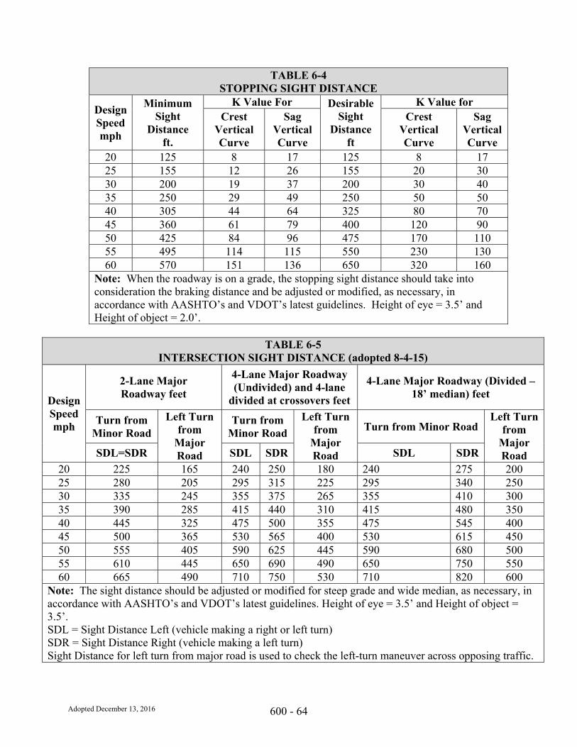
Adopted December 13, 2016 600 - 64
TABLE 6-4 STOPPING SIGHT DISTANCE
Design Speed mph
Minimum Sight
Distance ft.
K Value For Desirable Sight
Distance ft
K Value for Crest
Vertical Curve
Sag Vertical Curve
Crest Vertical Curve
Sag Vertical Curve
20 125 8 17 125 8 17 25 155 12 26 155 20 30 30 200 19 37 200 30 40 35 250 29 49 250 50 50 40 305 44 64 325 80 70 45 360 61 79 400 120 90 50 425 84 96 475 170 110 55 495 114 115 550 230 130 60 570 151 136 650 320 160
Note: When the roadway is on a grade, the stopping sight distance should take into consideration the braking distance and be adjusted or modified, as necessary, in accordance with AASHTO’s and VDOT’s latest guidelines. Height of eye = 3.5’ and Height of object = 2.0’.
TABLE 6-5
INTERSECTION SIGHT DISTANCE (adopted 8-4-15)
Design Speed mph
2-Lane Major Roadway feet
4-Lane Major Roadway (Undivided) and 4-lane
divided at crossovers feet
4-Lane Major Roadway (Divided – 18’ median) feet
Turn from Minor Road
Left Turn from
Major Road
Turn from Minor Road
Left Turn from
Major Road
Turn from Minor Road Left Turn
from Major Road SDL=SDR SDL SDR SDL SDR
20 225 165 240 250 180 240 275 200 25 280 205 295 315 225 295 340 250 30 335 245 355 375 265 355 410 300 35 390 285 415 440 310 415 480 350 40 445 325 475 500 355 475 545 400 45 500 365 530 565 400 530 615 450 50 555 405 590 625 445 590 680 500 55 610 445 650 690 490 650 750 550 60 665 490 710 750 530 710 820 600
Note: The sight distance should be adjusted or modified for steep grade and wide median, as necessary, in accordance with AASHTO’s and VDOT’s latest guidelines. Height of eye = 3.5’ and Height of object = 3.5’. SDL = Sight Distance Left (vehicle making a right or left turn) SDR = Sight Distance Right (vehicle making a left turn) Sight Distance for left turn from major road is used to check the left-turn maneuver across opposing traffic.
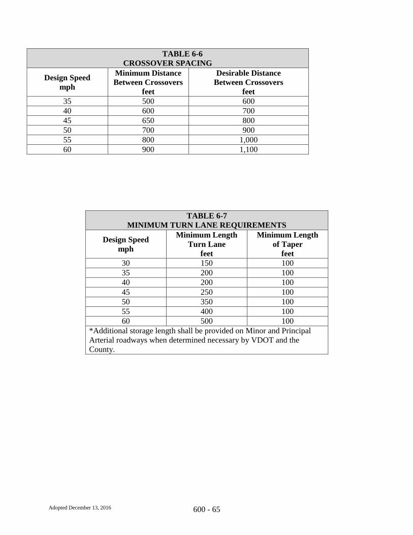
Adopted December 13, 2016 600 - 65
TABLE 6-6
CROSSOVER SPACING
Design Speed
mph
Minimum Distance
Between Crossovers
feet
Desirable Distance
Between Crossovers
feet
35 500 600
40 600 700
45 650 800
50 700 900
55 800 1,000
60 900 1,100
TABLE 6-7
MINIMUM TURN LANE REQUIREMENTS
Design Speed
mph
Minimum Length
Turn Lane
feet
Minimum Length
of Taper
feet
30 150 100
35 200 100
40 200 100
45 250 100
50 350 100
55 400 100
60 500 100
*Additional storage length shall be provided on Minor and Principal
Arterial roadways when determined necessary by VDOT and the
County.
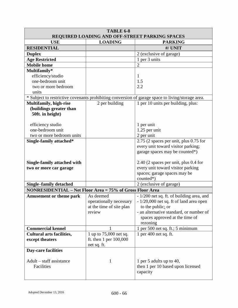
Adopted December 13, 2016 600 - 66
TABLE 6-8
REQUIRED LOADING AND OFF-STREET PARKING SPACES
USE LOADING PARKING
RESIDENTIAL #/ UNIT
Duplex 2 (exclusive of garage)
Age Restricted 1 per 3 units
Mobile home 2
Multifamily*
efficiency/studio
one-bedroom unit
two or more bedroom
units
1
1.5
2.2
* Subject to restrictive covenants prohibiting conversion of garage space to living/storage area.
Multifamily, high-rise
(buildings greater than
50ft. in height)
efficiency studio
one-bedroom unit
two or more bedroom units
2 per building 1 per 10 units per building, plus:
1 per unit
1.25 per unit
2 per unit
Single-family attached*
Single-family attached with
two or more car garage
2.75 (2 spaces per unit, plus 0.75 for
every unit toward visitor parking;
garage spaces may be counted*)
2.40 (2 spaces per unit, plus 0.4 for
every unit toward visitor parking
spaces; garage spaces may be
counted*)
Single–family detached 2 (exclusive of garage)
NONRESIDENTIAL – Net Floor Area = 75% of Gross Floor Area
Amusement or theme park As deemed
operationally necessary
at the time of site plan
review
- 1/200 net sq. ft. of building area, and
- 1/20,000 net sq. ft of land area open
to the public; or
- an alternative standard, or number of
spaces approved at the time of
rezoning
Commercial kennel 1 1 per 500 net sq. ft.; 5 minimum
Cultural arts facilities,
except theaters
1 up to 75,000 net sq.
ft. then 1 per 100,000
net sq. ft.
1 per 400 net sq. ft.
Day-care facilities
Adult – staff assistance
Facilities
1
1 per 5 adults up to 40,
then 1 per 10 based upon licensed
capacity

Adopted December 13, 2016 600 - 67
TABLE 6-8
REQUIRED LOADING AND OFF-STREET PARKING SPACES
USE LOADING PARKING
Adult – senior citizen
center
-----------------------------------
Child
1
---------------------------
none; 1 bus turnaround
area is to be provided
1 per 200 net sq. ft.
-----------------------------------------------
1 per 5 children up to 40 children,
then 1 per 10 children, based upon
licensed capacity
Farmer’s market 1 per 50,000 net sq. ft.;
2 minimum
1 per 400 net sq. ft. of sales area
Flea market 1 per 50,000 net sq. ft.;
2 minimum
1 per 200 net sq. ft.
Food store 1 up to 10,000 net. sq.
ft., then 1 per 20,000
net sq. ft.
1 per 200 net sq. ft.; 10 minimum
Fraternal lodge/civic club 1 1 per 150 net sq. ft.
Garden Center/
greenhouse/nursery
1 per 50,000 net sq. ft.
of interior floor area; 2
minimum
1 per 200 net. sq. ft. of indoor sales
plus 1 per 1,000 net sq. ft. of outdoor
and greenhouse sales (up to 100
spaces)
Heliport 1 10, plus 5 per tiedown
Helistop none 5 per tiedown or pad
Home Improvement
Center/hardware store
1, plus 1 per 30,000 sq.
ft. including outside
sales and storage.
1 per 200 net sq. ft. of indoor sales;
plus 1 per 2,000 net sq. ft. outdoor
sales and storage area.
Hospitals and other health
service facilities
Hospital – major surgical
or short term visits
----------------------------------
Medical center, offices
and clinics
----------------------------------
Nursing, convalescent or
Personal care facility
1 plus 1 per 75,000 net
sq. ft.
----------------------------
1 up to 75,000 net sq.
ft., then 2
---------------------------
1 up to 75,000 net sq.
ft., then 2
1.25 per bed
-----------------------------------------------
1 per 150 net sq. ft. up to 15,000 net
sq. ft., then 1 per 200 net sq. ft. up to
30,000 net sq. ft., then
1 per 250 net sq. ft. above 30,000 net
sq. ft.
-----------------------------------------------
1 per 2 beds, by licensed capacity
Hotels and motels (subject
to additional loading and
parking for ancillary uses)
1 1.2 per room
Libraries 1 1 per 125 net sq. ft.
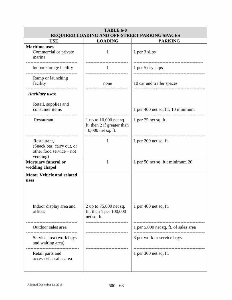
Adopted December 13, 2016 600 - 68
TABLE 6-8
REQUIRED LOADING AND OFF-STREET PARKING SPACES
USE LOADING PARKING
Maritime uses
Commercial or private
marina
----------------------------------
Indoor storage facility
----------------------------------
Ramp or launching
facility
----------------------------------
Ancillary uses:
Retail, supplies and
consumer items
----------------------------------
Restaurant
----------------------------------
Restaurant,
(Snack bar, carry out, or
other food service – not
vending)
1
----------------------------
1
----------------------------
none
----------------------------
----------------------------
1 up to 10,000 net sq.
ft. then 2 if greater than
10,000 net sq. ft.
----------------------------
1
1 per 3 slips
----------------------------------------------
1 per 5 dry slips
-----------------------------------------------
10 car and trailer spaces
-----------------------------------------------
1 per 400 net sq. ft.; 10 minimum
-----------------------------------------------
1 per 75 net sq. ft.
-----------------------------------------------
1 per 200 net sq. ft.
Mortuary funeral or
wedding chapel
1 1 per 50 net sq. ft.; minimum 20
Motor Vehicle and related
uses
Indoor display area and
offices
----------------------------------
Outdoor sales area
----------------------------------
Service area (work bays
and waiting area)
-----------------------------------
Retail parts and
accessories sales area
2 up to 75,000 net sq.
ft., then 1 per 100,000
net sq. ft.
----------------------------
----------------------------
----------------------------
1 per 400 net sq. ft.
-----------------------------------------------
1 per 5,000 net sq. ft. of sales area
-----------------------------------------------
3 per work or service bays
-----------------------------------------------
1 per 300 net sq. ft.

Adopted December 13, 2016 600 - 69
TABLE 6-8
REQUIRED LOADING AND OFF-STREET PARKING SPACES
USE LOADING PARKING
Heavy equipment sales
and services
Indoor display area and
offices
Outside sales area
----------------------------------
Service area (work bays
and waiting area)
----------------------------------
Retail parts and
accessories
----------------------------------
Additional Buildings
----------------------------------
Recreational vehicle
sales and services
Indoor display area and
offices
----------------------------------
Outside sales area
----------------------------------
Service area (work bays
and waiting area)
----------------------------------
Retail parts and
accessories
----------------------------------
Retail fuel sales
Fuel only
----------------------------------
Fuel with service
----------------------------------
Fuel with convenience
retail
1 per 25,000 net sq. ft.
----------------------------
----------------------------
----------------------------
----------------------------
1 per 25,000 net sq. ft.
----------------------------
----------------------------
----------------------------
----------------------------
1
----------------------------
1
----------------------------
1
1 per 500 net sq. ft., minimum 5
1 per 5,000 net sq. ft. of sales area
-----------------------------------------------
2 per work bay
-----------------------------------------------
1 per 300 net sq. ft.
-----------------------------------------------
1 per 1,000 net sq. ft.
-----------------------------------------------
1 per 400 net sq. ft.
-----------------------------------------------
1 per 2,500 net sq. ft. of sales area
-----------------------------------------------
2 per work bay
-----------------------------------------------
1 per 300 net sq. ft.
-----------------------------------------------
5
-----------------------------------------------
1 per 200 net sq. ft. of office/retail area
plus 3 per work bay; 10 minimum
-----------------------------------------------
5 plus 1 per 150 net sq. ft. of building
area; 10 minimum

Adopted December 13, 2016 600 - 70
TABLE 6-8
REQUIRED LOADING AND OFF-STREET PARKING SPACES
USE LOADING PARKING
Office, Financial
Institutions
----------------------------------
Office with ancillary retail
or service uses
Quick service food store
None for buildings with
less than 20,000 net sq.
ft. of building area;
then 1 for each
additional 20,000 net
sq. ft. Maximum of 5
loading spaces for each
building
---------------------------
1 per 20,000 net sq. ft.
up to 100,000 net sq.
ft., then 1 per 50,000
net sq. ft.
1
1 per 250 net sq. ft. of building area;
10 minimum
-----------------------------------------------
1 per 250 net sq. ft. plus 5%
1 per 150 net sq. ft. plus 2 up to 5,000
net sq. ft., plus 4 if greater than 5,000
net sq. ft.
Racetrack
Equestrian
-----------------------------------
Motorized vehicles
4, or as established by
SUP
---------------------------
4
1 per 2 seats plus 1 per 10 net sq. ft. of
designated standing area, or as
established by SUP
-----------------------------------------------
1 per 2 seats plus 1 per 10 net sq. ft. of
designated standing area, plus 1 trailer
space per work or service bay; 10
minimum
Recreational uses
Commercial
Arcade
----------------------------------
Billiard parlor
----------------------------------
Bowling Alley
----------------------------------
Alleys
----------------------------------
Retail area
Restaurant
none
----------------------------
1, if sales facility is on
premise
----------------------------
1, if sales facility or
restaurant is on premise
----------------------------
----------------------------
1 per 150 net sq. ft.
-----------------------------------------------
1 per 150 net sq. ft.
-----------------------------------------------
-----------------------------------------------
4 per lane
-----------------------------------------------
1 per 300 net sq. ft.
1 per 400 net sq. ft. of restaurant area

Adopted December 13, 2016 600 - 71
TABLE 6-8
REQUIRED LOADING AND OFF-STREET PARKING SPACES
USE LOADING PARKING
----------------------------------
Court sports facility
(single use)
----------------------------------
Fairground/carnival/
circus
----------------------------
none
----------------------------
4
-----------------------------------------------
4 per court plus 1 per 3 seats on stands
-----------------------------------------------
1 per 400 net sq. ft. of area
Golf course and service
facilities, single use
----------------------------------
Miniature golf/driving
range (single use)
----------------------------------
Petting farms
-----------------------------------
Pony rides/kiddie parks
----------------------------------
Private recreational facility
or club
plus parking per the
following uses
Restaurant, ancillary
-----------------------------------
Retail, ancillary
-----------------------------------
Active recreational uses
(not courts or golf
courses)
----------------------------------
Hard or soft courts
----------------------------------
Regulation sports fields
(softball, baseball, soccer,
football, lacrosse, etc.)
----------------------------------
Swimming pools
-----------------------------------
Public recreational
facility/club
none
----------------------------
none
----------------------------
none
---------------------------
none
----------------------------
1 if over 30,000 net sq.
ft.
1
----------------------------
none
----------------------------
none
----------------------------
none
----------------------------
none
----------------------------
1
----------------------------
1 if over 30,000 net sq.
ft.
3 per hole
-----------------------------------------------
2 per tee for the first 36 tees, then 1
per tee
-----------------------------------------------
1 per 20,000 net sq. ft. of the area open
to the public
-----------------------------------------------
1 per 20,000 net sq. ft. of the area open
to the public
-----------------------------------------------
1 per 150 net sq. ft.
1 per 200 net sq. ft.
-----------------------------------------------
1 per 300 net sq. ft.
-----------------------------------------------
3 per acre
-----------------------------------------------
4 per court
-----------------------------------------------
30 per field
-----------------------------------------------
1 per 150 sq. ft. of water surface area
-----------------------------------------------
1 per 150 net sq. ft.
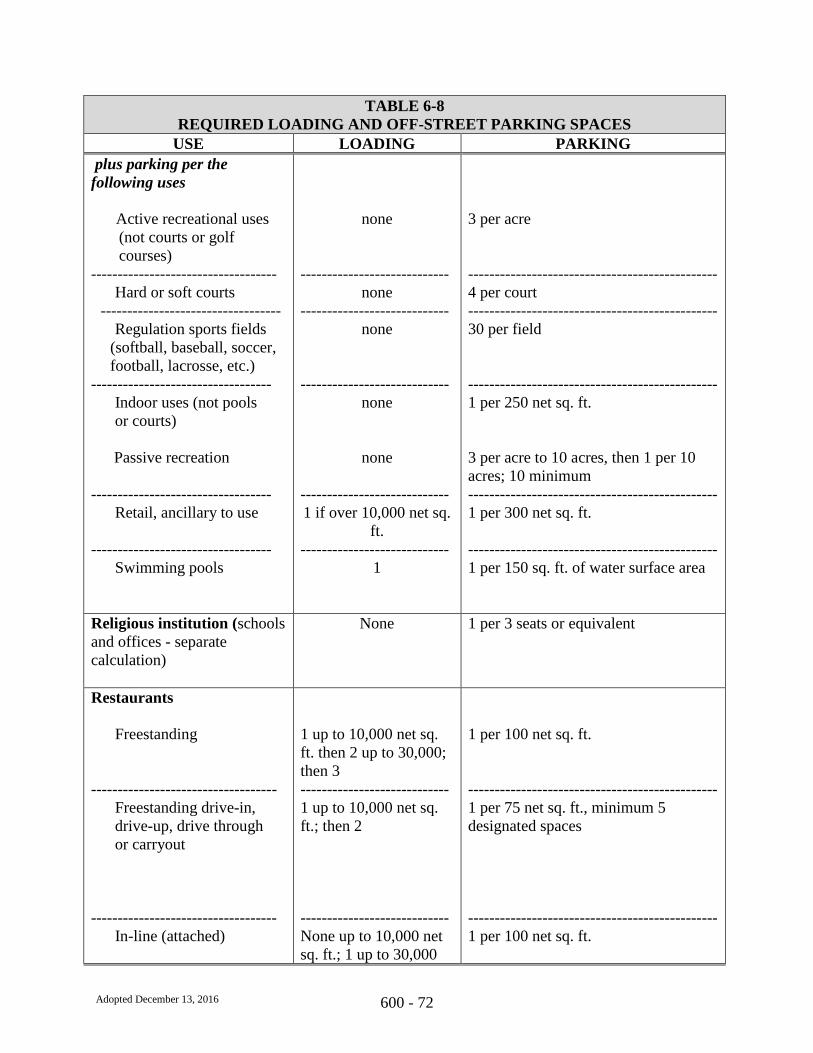
Adopted December 13, 2016 600 - 72
TABLE 6-8
REQUIRED LOADING AND OFF-STREET PARKING SPACES
USE LOADING PARKING
plus parking per the
following uses
Active recreational uses
(not courts or golf
courses)
-----------------------------------
Hard or soft courts
----------------------------------
Regulation sports fields
(softball, baseball, soccer,
football, lacrosse, etc.)
----------------------------------
Indoor uses (not pools
or courts)
Passive recreation
----------------------------------
Retail, ancillary to use
----------------------------------
Swimming pools
none
----------------------------
none
----------------------------
none
----------------------------
none
none
----------------------------
1 if over 10,000 net sq.
ft.
----------------------------
1
3 per acre
-----------------------------------------------
4 per court
-----------------------------------------------
30 per field
-----------------------------------------------
1 per 250 net sq. ft.
3 per acre to 10 acres, then 1 per 10
acres; 10 minimum
-----------------------------------------------
1 per 300 net sq. ft.
-----------------------------------------------
1 per 150 sq. ft. of water surface area
Religious institution (schools
and offices - separate
calculation)
None 1 per 3 seats or equivalent
Restaurants
Freestanding
-----------------------------------
Freestanding drive-in,
drive-up, drive through
or carryout
-----------------------------------
In-line (attached)
1 up to 10,000 net sq.
ft. then 2 up to 30,000;
then 3
----------------------------
1 up to 10,000 net sq.
ft.; then 2
----------------------------
None up to 10,000 net
sq. ft.; 1 up to 30,000
1 per 100 net sq. ft.
-----------------------------------------------
1 per 75 net sq. ft., minimum 5
designated spaces
-----------------------------------------------
1 per 100 net sq. ft.

Adopted December 13, 2016 600 - 73
TABLE 6-8
REQUIRED LOADING AND OFF-STREET PARKING SPACES
USE LOADING PARKING
net sq. ft.; then 1 per
50,000 net sq. ft.
Retail sales and services and
similar uses not specifically
addressed including
shopping centers
None up to 10,000 net
sq. ft.; then 1 for up to
30,000 net sq. ft.; then
1 for up to 50,000 net
sq. ft.; then 1 for up to
100,000 net sq. ft.; then
1 per 100,000 net sq. ft.
after that
1 per 200 net sq. ft. up to 50,000 net
sq. ft.; then 1 per 225 net sq. ft. up to
300,000 net sq. ft.; then 1 per 250 net
sq. ft. after that.
School of special instruction,
business or trade
none 1 per 200 net sq. ft.
Schools, public and private
Learning Center
-----------------------------------
Elementary or Middle
Schools
-----------------------------------
High Schools
----------------------------------
Junior colleges,
colleges, universities
1
----------------------------
2
----------------------------
2
----------------------------
2
1/seat
-----------------------------------------------
1 space for every 20 classroom seats
plus 5 visitor spaces, plus one space
for every 5 seats in an auditorium or
multipurpose room
-----------------------------------------------
1 space for every 5 students, plus one
per faculty member, plus 10 spaces for
visitors, plus one space for every 4
seats in an auditorium or multipurpose
room
-----------------------------------------------
1 space for every 5 classroom seats,
plus 20 spaces for visitors, plus one
space for every 3 seats in an
auditorium or multipurpose room
Self-storage center none 3.2 spaces per 1,000 net sq. ft. of
office plus 1 space per employee and 2
spaces for the resident manager
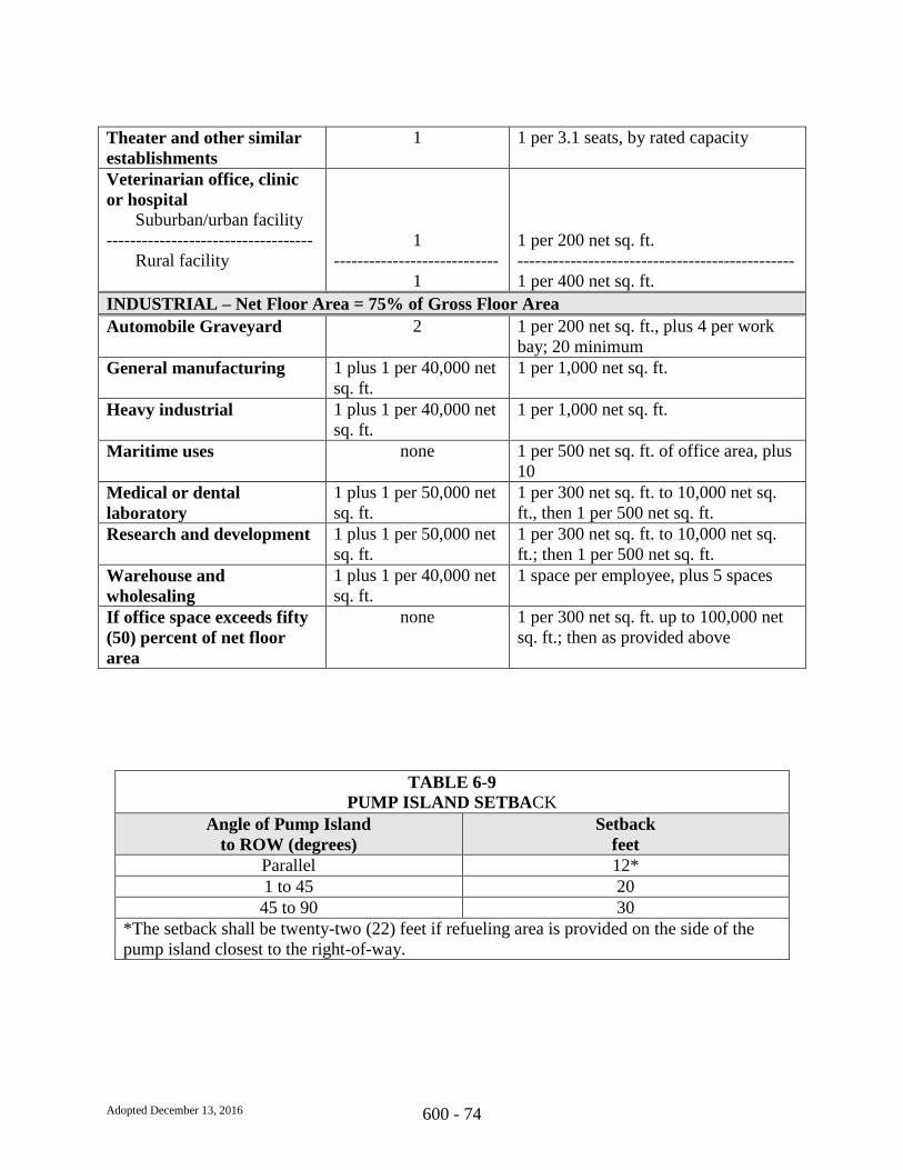
Adopted December 13, 2016 600 - 74
Theater and other similar
establishments
1 1 per 3.1 seats, by rated capacity
Veterinarian office, clinic
or hospital Suburban/urban facility
-----------------------------------
Rural facility
1
----------------------------
1
1 per 200 net sq. ft.
-----------------------------------------------
1 per 400 net sq. ft.
INDUSTRIAL – Net Floor Area = 75% of Gross Floor Area
Automobile Graveyard 2
1 per 200 net sq. ft., plus 4 per work
bay; 20 minimum
General manufacturing 1 plus 1 per 40,000 net
sq. ft.
1 per 1,000 net sq. ft.
Heavy industrial 1 plus 1 per 40,000 net
sq. ft.
1 per 1,000 net sq. ft.
Maritime uses none 1 per 500 net sq. ft. of office area, plus
10
Medical or dental
laboratory
1 plus 1 per 50,000 net
sq. ft.
1 per 300 net sq. ft. to 10,000 net sq.
ft., then 1 per 500 net sq. ft.
Research and development 1 plus 1 per 50,000 net
sq. ft.
1 per 300 net sq. ft. to 10,000 net sq.
ft.; then 1 per 500 net sq. ft.
Warehouse and
wholesaling
1 plus 1 per 40,000 net
sq. ft.
1 space per employee, plus 5 spaces
If office space exceeds fifty
(50) percent of net floor
area
none 1 per 300 net sq. ft. up to 100,000 net
sq. ft.; then as provided above
TABLE 6-9
PUMP ISLAND SETBACK
Angle of Pump Island
to ROW (degrees)
Setback
feet
Parallel 12*
1 to 45 20
45 to 90 30
*The setback shall be twenty-two (22) feet if refueling area is provided on the side of the
pump island closest to the right-of-way.
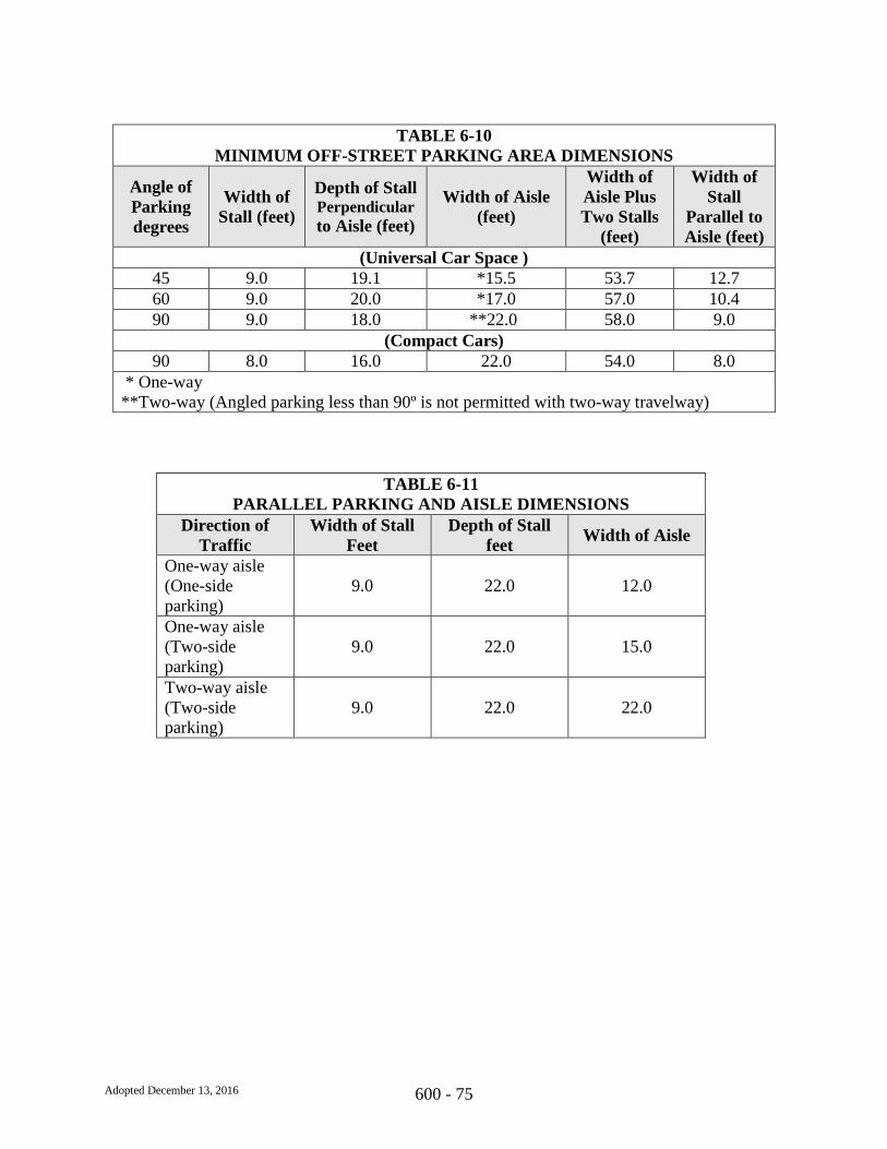
Adopted December 13, 2016 600 - 75
TABLE 6-10
MINIMUM OFF-STREET PARKING AREA DIMENSIONS
Angle of
Parking
degrees
Width of
Stall (feet)
Depth of Stall Perpendicular
to Aisle (feet)
Width of Aisle
(feet)
Width of
Aisle Plus
Two Stalls
(feet)
Width of
Stall
Parallel to
Aisle (feet)
(Universal Car Space )
45 9.0 19.1 *15.5 53.7 12.7
60 9.0 20.0 *17.0 57.0 10.4
90 9.0 18.0 **22.0 58.0 9.0
(Compact Cars)
90 8.0 16.0 22.0 54.0 8.0
* One-way
**Two-way (Angled parking less than 90º is not permitted with two-way travelway)
TABLE 6-11
PARALLEL PARKING AND AISLE DIMENSIONS
Direction of
Traffic
Width of Stall
Feet
Depth of Stall
feet Width of Aisle
One-way aisle
(One-side
parking)
9.0 22.0 12.0
One-way aisle
(Two-side
parking)
9.0 22.0 15.0
Two-way aisle
(Two-side
parking)
9.0 22.0 22.0
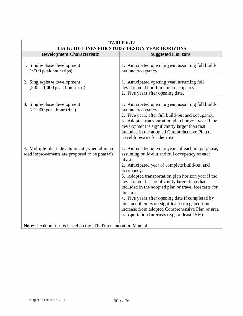
Adopted December 13, 2016 600 - 76
TABLE 6-12
TIA GUIDELINES FOR STUDY DESIGN YEAR HORIZONS
Development Characteristic Suggested Horizons
1. Single-phase development
(<500 peak hour trips)
1. Anticipated opening year, assuming full build-
out and occupancy.
2. Single-phase development
(500 – 1,000 peak hour trips)
1. Anticipated opening year, assuming full
development build-out and occupancy.
2. Five years after opening date.
3. Single-phase development
(>1,000 peak hour trips)
1. Anticipated opening year, assuming full build-
out and occupancy.
2. Five years after full build-out and occupancy.
3. Adopted transportation plan horizon year if the
development is significantly larger than that
included in the adopted Comprehensive Plan or
travel forecasts for the area.
4. Multiple-phase development (when ultimate
road improvements are proposed to be phased)
1. Anticipated opening years of each major phase,
assuming build-out and full occupancy of each
phase.
2. Anticipated year of complete build-out and
occupancy.
3. Adopted transportation plan horizon year if the
development is significantly larger than that
included in the adopted plan or travel forecasts for
the area.
4. Five years after opening date if completed by
then and there is no significant trip generation
increase from adopted Comprehensive Plan or area
transportation forecasts (e.g., at least 15%)
Note: Peak hour trips based on the ITE Trip Generation Manual
Adopted December 13, 2016 600 - 77
650.00 TRANSPORTATION SYSTEMS - DETAILS

THESEALPRIN
CEWILLIAMCOU
NTYVA
COUNTY OFPRINCE WILLIAM
VIRGINIADate
Detail No.
7/15/14650.01STANDARD PAVEMENT DESIGN
(SHEET 1 OF 3)
*For traffic volumes over 10,000 vehicles per day, use SM-9.5D for surface course.
9 inches Asph. Conc Type BM-25.0A
and 2 inches Asph. Conc. Type IM-19.0A4 inches Asph. Conc Type BM-25.0A
3 inches Asph. Conc Type BM-25.0A
5 inches Asph. Conc Type BM-25.0A6 inches Asph. Conc Type BM-25.0A
7 inches Asph. Conc Type BM-25.0A8 inches Asph. Conc Type BM-25.0A5 inches Asph. Conc Type BM-25.0
6 inches Agg. Base Material4 inches Asph. Conc Type BM-25.0A6 inches Asph. Conc Type BM-25.0A
4 inches Asph. Conc Type BM-25.0A3 inches Asph. Conc Type BM-25.0A3 inches Asph. Conc Type BM-25.0A3 inches Asph. Conc Type BM-25.0A8 inches Agg. Base Material
4 inches Agg. Base Material6 inches Agg. Base Material
TABLE II PAVEMENT STRUCTURE DESIGN
7,001 (PLUS) VPD
4,001 TO 7,000 VPD
2,001 TO 4,000 VPD
1,001 TO 2,000 VPD
401 TO 1,000 VPD
251 TO 400 VPD
UP TO 250 VPD
2. 6 inches Cement Treated Aggregate
2. 8 inches Agg. Subbase or Base Material
1. 6 inches Cement Treated Aggregate
3. 6 inches Cement Treated Aggregate2. 8 inches Agg. Subbase or Base Material1. 8 inches Agg. Subbase or Base Material
3. 8 inches Agg. Subbase or Base Material2. 8 inches Agg. Subbase or Base Material
5 inches Agg. Subbase or Base Material1. 6 inches Cement Treated Aggregate &
3. 8 inches Agg. Subbase or Base Material2. 8 inches Agg. Subbase or Base Material1. 6 inches Cement Treated Aggregate
3. 8 inches Agg. Subbase or Base Material
VII*
1. 8 inches Agg. Subbase or Base Material
2. 6 inches Agg. Subbase or Base Material
2. 4 inches (Select Material Type I, II or III)
SUBBASE
1. N/A
1. N/A
CATEGORY
I1-1/2 inches A.C.
2 inches Asph. Conc
2 inches Asph. Conc
1-1/2 inches Asph. Conc
2 inches Asph. Conc2 inches Asph. Conc
TYPE SM-9.5ASURFACE
BASE
2 inches Asph. Conc2 inches Asph. Conc
2 inches Asph. Conc2 inches Asph. Conc
2 inches Asph. Conc2 inches Asph. Conc1-1/2 inches Asph. Conc
1-1/2 inches Asph. Conc
1-1/2 inches Asph. Conc
1-1/2 inches Asph. Conc
2 inches Asph. Conc2 inches Asph. Conc
(SM-9.5D)
SPD-1

THESEALPRINC
EWILLIAMCOU
NTYVA
COUNTY OFPRINCE WILLIAM
VIRGINIADate
Detail No.
7/15/14650.01
GENERAL NOTES:
SPD-1 STANDARD PAVEMENT DESIGN(SHEET 2 OF 3)
1. When the projected traffic requires a four lane facility, 80% of the projected traffic shall be the basis fordetermining the applicable class for the pavement structure design.
2. Subgrade support soils, immediately under the pavement, with CBR values of less than ten will require anadditional six (6) inches of subbase or base. In lieu of this, the CBR value may be improved by any otheracceptable means. In any case, the subbase aggregate shall not exceed twelve (12) inches.
3. Sufficient engineer certified CBR tests must be run to determine the soil support value (SSV) of the various soils inthe subgrade. Details to the VDOT approved method may be obtained through any VDOT District or Residency Officeor its Central Office.
4. Pavement design in accordance with "Pavement Design Guide of Subdivision and Secondary Roads in Virginia" ofVDOT is acceptable an alternate to any of the above.
5. Each street should have continuity of design throughout. Therefore, multiple and/or variable base design will onlyoccur at the intersections.
6. Designs within a specific traffic category may not be structurally equal because of differences in the materials'flexural strengths and practical construction consideration.
7. Cement Treated Aggregate (CTA) or full depth Bituminous Concrete can be substituted for any aggregate, subgradestabilization, or select material on a basis of one (1) inch of CTA or Bituminous Concrete for two (2) inches of theother materials. Neither CTA nor Bituminous Concrete should be placed directly on a resilient soil unless the soil isstabilized with cement or other stabilizing agent. CTA should have a minimum of four (4) inches of aggregatematerial under it when less than four (4) inches of bituminous concrete is used on top of the CTA.
8. UD-1's must be used with high water tables. UD-2's must be used for all pavement sections with grassed medians.
9. Subsurface and pavement drainage problems must be corrected in accordance with current VDOT standards.
10. The pavement designs in the tables are based on an assumed CBR value of 10 and are recommended as aguide. The actual designs shall be based upon the traffic volume and CBR values for specific projects.
11. Categories IV thru VII or any street intended to carry a design traffic volume exceeding 1,000 VPD shall utilize21B aggregate as subbase or base material. Pavement drainage, such as the use of underdrains, should be providedin the pavement design when 21B aggregate is used.

THESEALPRINC
EWILLIAMCOU
NTYVA
COUNTY OFPRINCE WILLIAM
VIRGINIADate
Detail No.
7/15/14650.01
GENERAL NOTES (continued):
STANDARD PAVEMENT DESIGN(SHEET 3 OF 3)SPD-1
12. The maximum combined thickness of subbase and base layers of aggregate materials shall be twelve (12)inches. Any thickness index that requires an aggregate layer over twelve (12) inches should be developedthrough appropriate treatment of subgrade or through the use of thicker asphalt concrete layers.
13. Plain aggregate should be primed with liquid asphalt material in accordance with VDOT specifications wheneverFour (4) inches or less of asphalt is to be placed on a plain or cement stabilized aggregate.
14. Paved shoulders, where required, should be designed in accordance with VDOT standards and specifications.
15. Superpave mixes when required by Department of Transportation and VDOT, shall be designed in accordance withthe minimum requirements of VDOT and this manual. Pavement layers thickness design, material requirements,mix design criteria, job mix formula and specifications shall be in accordance Section 211 of VDOT Road andBridge Specifications Manual and current Special Provisions.

COUNTY OF
PRINCE WILLIAMVIRGINIA
Date
Detail No.
7/15/14650.02RL-1
STANDARD TYPICAL SECTION FOR
RESIDENTIAL LOCAL STREETS WITHOUT CURB AND GUTTER
(FIXED TRAFFIC)
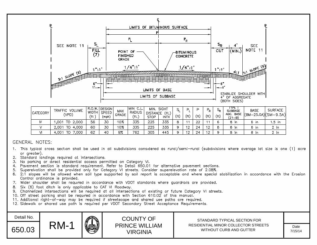
COUNTY OF
PRINCE WILLIAMVIRGINIA
Date
Detail No.
7/15/14650.03 RM-1STANDARD TYPICAL SECTION FOR
RESIDENTIAL MINOR COLLECTOR STREETS
WITHOUT CURB AND GUTTER

COUNTY OF
PRINCE WILLIAM
VIRGINIA
Date
Detail No.
01/20/2017650.04
SYMMETRICAL
RL-2
STANDARD TYPICAL SECTION FOR
RESIDENTIAL LOCAL STREETS
WITH CURB AND GUTTER
(FIXED TRAFFIC)

COUNTY OF
PRINCE WILLIAMVIRGINIA
Date
Detail No.
7/15/14650.05 RM-2STANDARD TYPICAL SECTION FOR
RESIDENTIAL MINOR COLLECTOR STREETS
WITH CURB AND GUTTER
SYMMETRICAL

COUNTY OF
PRINCE WILLIAMVIRGINIA
Date
Detail No.
7/15/14650.06 TS-1TRAVELWAY STANDARDS FOR
INDUSTRIAL, INSTITUTIONAL, OFFICE,
COMMERCIAL, SINGLE FAMILY ATTACHED,
AND MULTIFAMILY DEVELOPMENTS

COUNTY OF
PRINCE WILLIAMVIRGINIA
Date
Detail No.
7/15/14650.07 MF-1STANDARD TYPICAL SECTION FOR
CONDOMINIUM, MOBILE HOME,AND APARTMENT STREETS
WITH NO RESIDENTIAL FRONTAGE
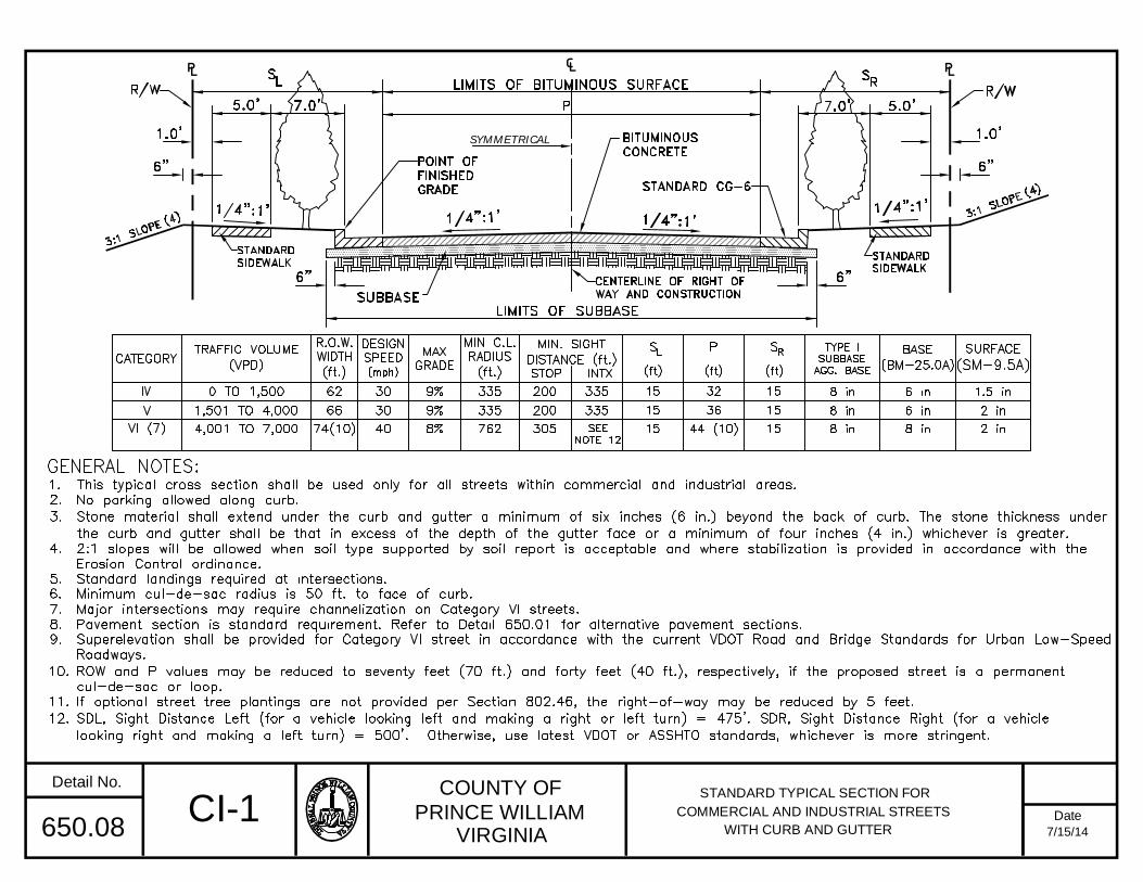
COUNTY OF
PRINCE WILLIAMVIRGINIA
Date
Detail No.
7/15/14650.08CI-1
STANDARD TYPICAL SECTION FOR
COMMERCIAL AND INDUSTRIAL STREETS
WITH CURB AND GUTTER
SYMMETRICAL

COUNTY OF
PRINCE WILLIAMVIRGINIA
Date
Detail No.
7/15/14650.09 MC-1STANDARD TYPICAL SECTION FOR MAJORCOLLECTOR STREETS AS DESIGNATED BY
THE COMPREHENSIVE PLAN (4 LANEDIVIDED WITH CURB AND GUTTER

COUNTY OF
PRINCE WILLIAMVIRGINIA
Date
Detail No.
7/15/14650.10
MC-2STANDARD TYPICAL SECTION FOR
MAJOR COLLECTOR STREETS AND MINOR
ARTERIAL STREETS AS DESIGNATED BY THE
MA-2 COMPREHENSIVE PLAN (4 LANE DIVIDEDWITHOUT CURB AND GUTTER)

COUNTY OF
PRINCE WILLIAMVIRGINIA
Date
Detail No.
7/15/14650.11 MA-1STANDARD TYPICAL SECTION FOR URBAN
MINOR ARTERIAL STREETS AS DESIGNATEDBY THE COMPREHENSIVE PLAN
(6 LANE DIVIDED WITH CURB AND GUTTER)
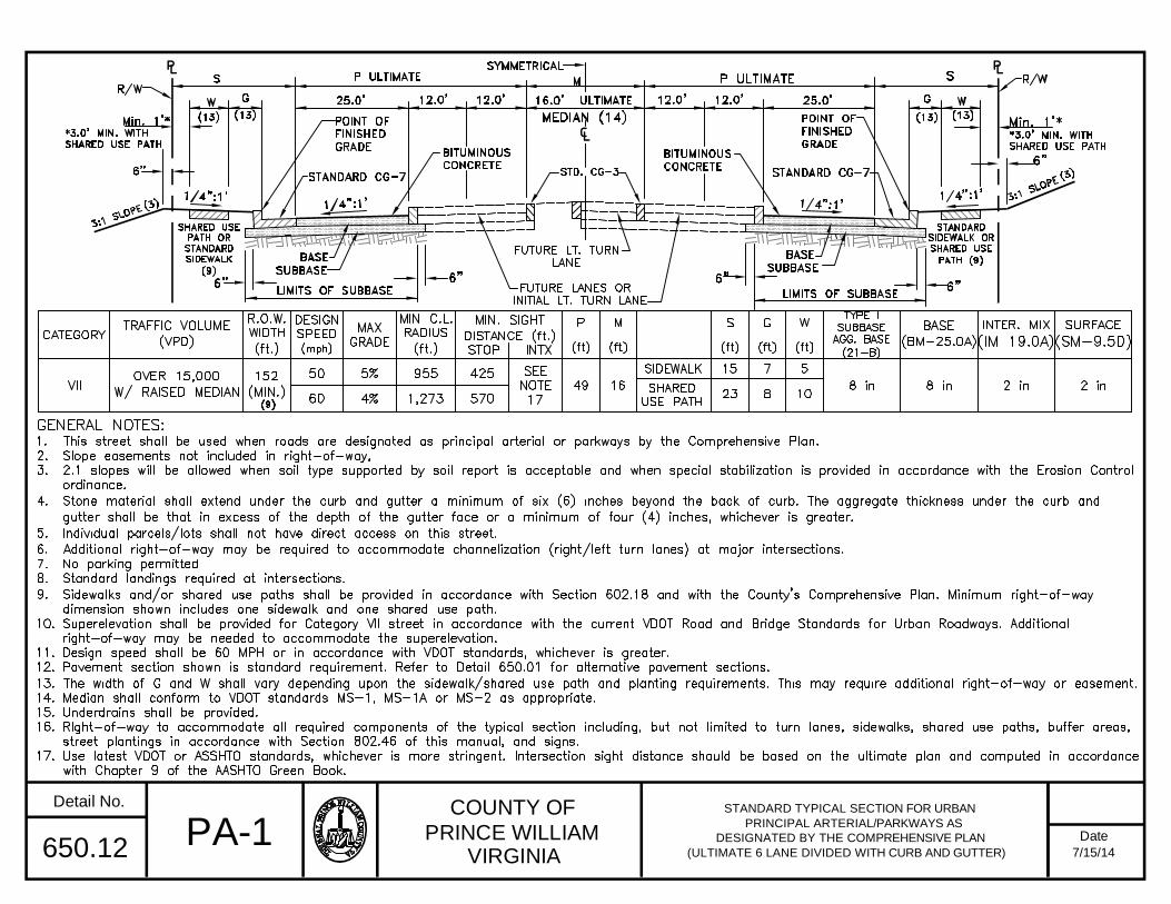
COUNTY OF
PRINCE WILLIAMVIRGINIA
Date
Detail No.
7/15/14650.12 PA-1 PRINCIPAL ARTERIAL/PARKWAYS AS
DESIGNATED BY THE COMPREHENSIVE PLAN
(ULTIMATE 6 LANE DIVIDED WITH CURB AND GUTTER)
STANDARD TYPICAL SECTION FOR URBAN

COUNTY OF
PRINCE WILLIAMVIRGINIA
Date
Detail No.
7/15/14650.13 PA-2STANDARD TYPICAL SECTION FOR
PRINCIPAL ARTERIAL/PARKWAYS ASDESIGNATED BY THE COMPREHENSIVE PLAN
(4 LANE DIVIDED INITIALLY)
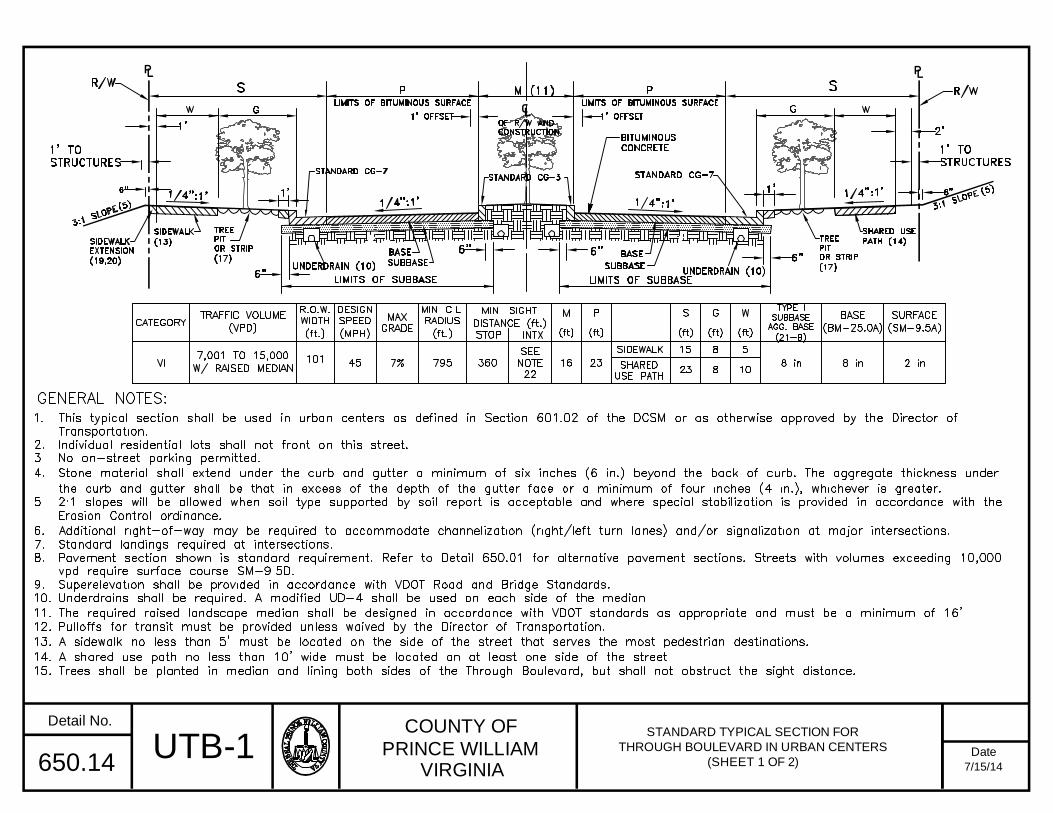
COUNTY OF
PRINCE WILLIAMVIRGINIA
Date
Detail No.
7/15/14650.14UTB-1
STANDARD TYPICAL SECTION FOR
THROUGH BOULEVARD IN URBAN CENTERS
(SHEET 1 OF 2)
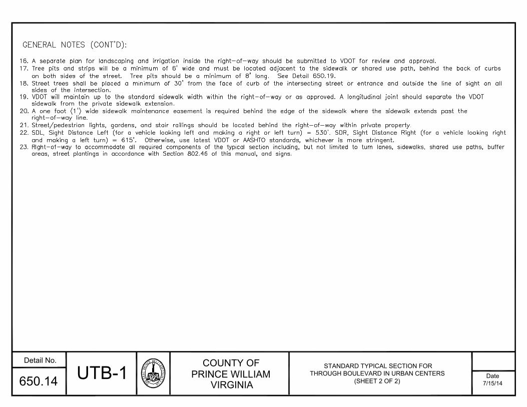
THESEALPRINC
EWILLIAMCOU
NTYVA
COUNTY OFPRINCE WILLIAM
VIRGINIADate
Detail No.
7/15/14650.14
16. A separate plan for landscaping and irrigation inside the right-of-way should be submitted to VDOT for review and approval.17. Tree pits and strips will be a minimum of 6' wide and must be located adjacent to the sidewalk or shared use path, behind the back of curbs
on both sides of the street. Tree pits should be a minimum of 8' long. See Detail 650.19.18. Street trees shall be placed a minimum of 30' from the face of curb of the intersecting street or entrance and outside the line of sight on all
sides of the intersection.19. VDOT will maintain up to the standard sidewalk width within the right-of-way or as approved. A longitudinal joint should separate the VDOT
sidewalk from the private sidewalk extension.20. A one foot (1') wide sidewalk maintenance easement is required behind the edge of the sidewalk where the sidewalk extends past the
right-of-way line.21. Street/pedestrian lights, gardens, and stair railings should be located behind the right-of-way within private property.22. SDL, Sight Distance Left (for a vehicle looking left and making a right or left turn) = 530'. SDR, Sight Distance Right (for a vehicle looking right
and making a left turn) = 615'. Otherwise, use latest VDOT or AASHTO standards, whichever is more stringent.23. RIght-of-way to accommodate all required components of the typical section including, but not limited to turn lanes, sidewalks, shared use paths, buffer
areas, street plantings in accordance with Section 802.46 of this manual , and sig ns.
GENERAL NOTES (CONT'D):
STANDARD TYPICAL SECTION FORTHROUGH BOULEVARD IN URBAN CENTERS
(SHEET 2 OF 2)UTB-1

COUNTY OF
PRINCE WILLIAMVIRGINIA
Date
Detail No.
7/15/14650.15
SYMMETRICAL
SYMMETRICAL
(SHEET 1 OF 3)
STANDARD TYPICAL SECTION FOR
BOULEVARD
IN URBAN CENTERSUB-1
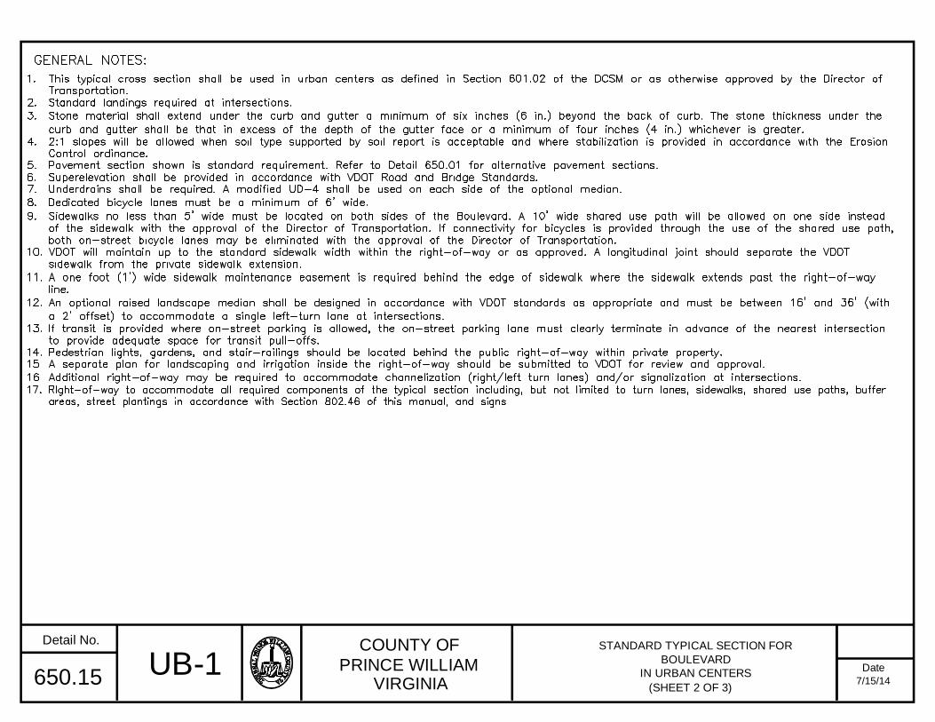
COUNTY OF
PRINCE WILLIAMVIRGINIA
Date
Detail No.
7/15/14650.15
STANDARD TYPICAL SECTION FOR
BOULEVARD
IN URBAN CENTERS
(SHEET 2 OF 3)
UB-1

COUNTY OF
PRINCE WILLIAMVIRGINIA
Date
Detail No.
7/15/14650.15
OPTION WITH CURB EXTENSION (5)OPTION WITHOUT CURB EXTENSION
LAYOUT DESIGN FOR BOULEVARD IN
URBAN CENTERS
(SHEET 3 OF 3)UB-1

COUNTY OF
PRINCE WILLIAMVIRGINIA
Date
Detail No.
7/15/14650.16
STANDARD TYPICAL SECTION FOR
AVENUE AND STREET IN URBAN CENTERS
(SHEET 1 OF 4)
SYMMETRICAL
SYMMETRICAL
UAS-1
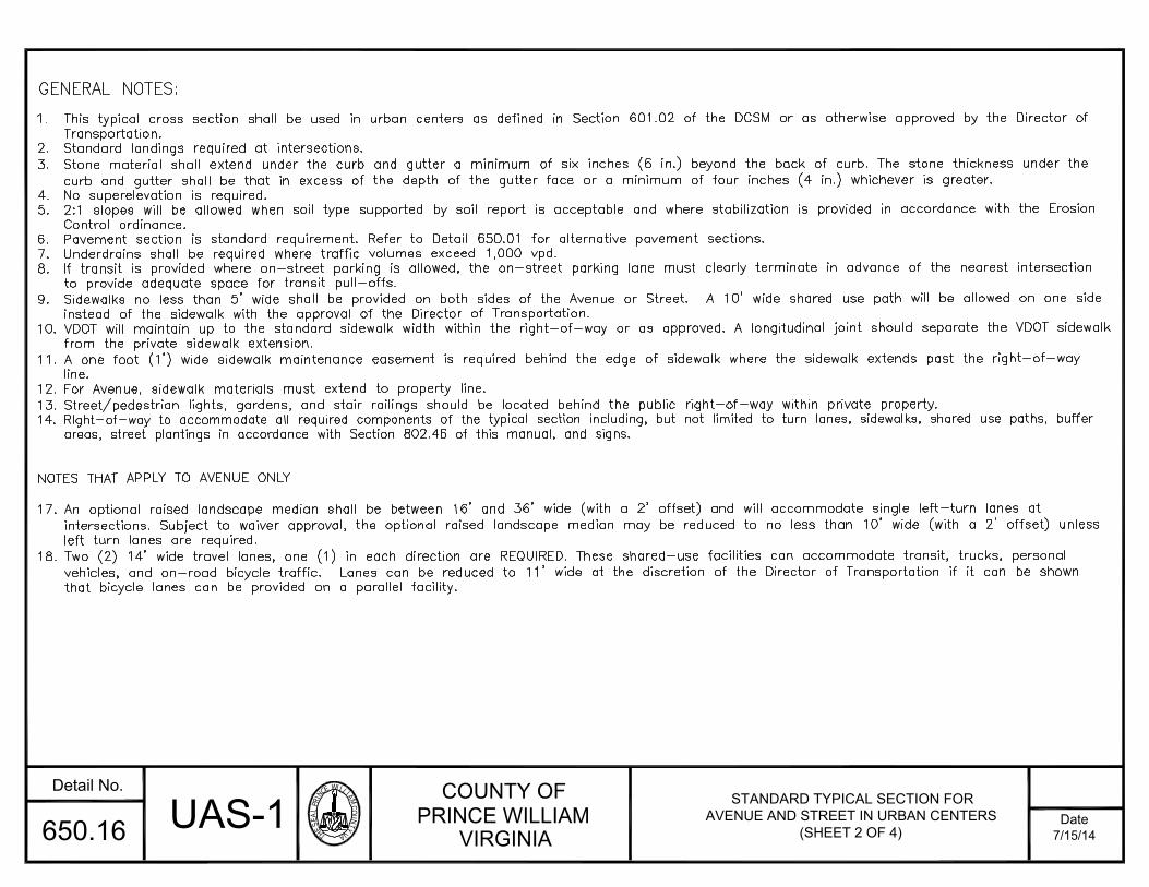
THESEALPRINC
EWILLIAMCOU
NTYVA
COUNTY OFPRINCE WILLIAM
VIRGINIADate
Detail No.
7/15/14650.16
1. This typical cross section shall be used in urban centers as defined in Section 601.02 of the DCSM or as otherwise approved by the Director ofTransportation.
2. Standard landings required at intersections.3. Stone material shall extend under the curb and gutter a minimum of six inches (6 in.) beyond the back of curb. The stone thickness under the
curb and gutter shall be that in excess of the depth of the gutter face or a minimum of four inches (4 in.) whichever is greater.4. No superelevation is required.5. 2:1 slopes will be allowed when soil type supported by soil report is acceptable and where stabilization is provided in accordance with the Erosion
Control ordinance.6. Pavement section is standard requirement. Refer to Detail 650.01 for alternative pavement sections.7. Underdrains shall be required where traffic volumes exceed 1,000 vpd.8. If transit is provided where on-street parking is allowed, the on-street parking lane must clearly terminate in advance of the nearest intersection
to provide adequate space for transit pull-offs.9. Sidewalks no less than 5' wide shall be provided on both sides of the Avenue or Street. A 10' wide shared use path will be allowed on one side
instead of the sidewalk with the approval of the Director of Transportation.10. VDOT will maintain up to the standard sidewalk width within the right-of-way or as approved. A longitudinal joint should separate the VDOT sidewalk
from the private sidewalk extension.11. A one foot (1') wide sidewalk maintenance easement is required behind the edge of sidewalk where the sidewalk extends past the right-of-way
line.12. For Avenue, sidewalk materials must extend to property line.13. Street/pedestrian lights, gardens, and stair railings should be located behind the public right-of-way within private property.14. RIght-of-way to accommodate all required components of the typical section including, but not limited to turn lanes, sidewalks, shared use paths, buffer
areas, street plantings in accordance with Section 802.46 of this manual , and sig ns.
NOTES THAT APPLY TO AVENUE ONLY
17. An optional raised landscape median shall be between 16' and 36' wide (with a 2' offset) and will accommodate single left-turn lanes atintersections. Subject to waiver approval, the optional raised landscape median may be reduced to no less than 10' wide (with a 2' offset) unlessleft turn lanes are required.
18. Two (2) 14' wide travel lanes, one (1) in each direction are REQUIRED. These shared-use facilities can accommodate transit, trucks, personalvehicles, and on-road bicycle traffic. Lanes can be reduced to 11' wide at the discretion of the Director of Transportation if it can be shownthat bicycle lanes can be provided on a parallel facility.
GENERAL NOTES:
STANDARD TYPICAL SECTION FORAVENUE AND STREET IN URBAN CENTERS
(SHEET 2 OF 4)UAS-1

THESEALPRINC
EWILLIAMCOU
NTYVA
COUNTY OFPRINCE WILLIAM
VIRGINIADate
Detail No.
7/15/14650.16
BCR
ECR
BCR
ECR
B
A
A
SIDEWALK
B
30'
MIN(1)
CURBRAMP
(4)
6.0'
8.0
'
CURB
RAMP
(4)
6.0' MIN.CROSSWALK
2.0' STOPBAR
25.0' MINNO PARKING
ZONE (3)
22.0' MINTYP. PARKING
SPACE (2) 14.0'8.0'
1.0'
4.0'
TR
AV
EL
LANE
PA
RK
ING
1.0'
5.0'
25.0' MINNO PARKING
ZONE (3)22.0' MIN
TYP. PARKING
SPACE (2)
OPTIONALMEDIAN
1.0' R/W
1. Street trees shall be placed a minimum of 30' from the face of curb of the intersecting street or entrance and outside the line of sight on allsides of the intersection.
2. Parallel parking spaces are 22' long and 8' wide.3. "No Parking Zone" is measured from the end or beginning of curb radius for a minimum distance of 25' or longer to accommodate intersection
sight distance, transit, and turning movemen ts.
4. Refer to current VDOT CG-12 standards for design of curb ramps and other available curb ramp options.5. An optional curb extension to the edge of parking at intersection corners is permitted. The turning characteristics of a 45' long bus must be
adequately demonstrated.6. Street trees must be planted centered within a tree pit. See Detail 650.19.7. Tree pits shall be located between sidewalk and the back of curb and shall be no less than 6' wide and 8' long.8. Sidewalk width at corners must be maintained by truncating property boundary if necessary.9. Extra right-of-way may be needed at signalized intersections.10. A separate plan for landscaping and irrigation inside the right-of-way should be submitted to VDOT for review and approval.11. Shared bicycle lane markings should be placed in accordance with the latest version of the Manual of Uniform Traffic Control Devices (MUTCD).
GENERAL NOTES:
5.0'
(8)
OPTION WITH CURB EXTENSION (5)OPTION WITHOUT CURB EXTENSION
14.0' 8.0'
TR
AV
EL
LANEPARKING
1.0' OFFSET FROMF.O.C. TO TRAVELLANE
1.0'
1.0'
4.0'
6.0'
8.0
'
5.0'
1.0' R/W
2.0'28' MIN. + MED.WIDTH + 2' OFFSET
6.0' MIN.CROSSWALK
4.0'
MIN.
4.0'
MIN.LAYOUT DESIGN FOR AVENUE
IN URBAN CENTERS(SHEET 3 OF 4)
UAS-1
TREE PIT
(6,7)
TREE PIT (6,7)
A
SIDEWALK
B
CURVE RADIUS
25.0' MIN.
20.0'
B
B
30'
MIN(1)
ALL RADII SHOWN FOR FACEOF CURB
ECR - END CURB RADIUS
BCR - BEGIN CURB RADIUS
TREE PIT (6,7)
TREE PIT (6,7)
1.0'
1.0'
1.0'
1.0'
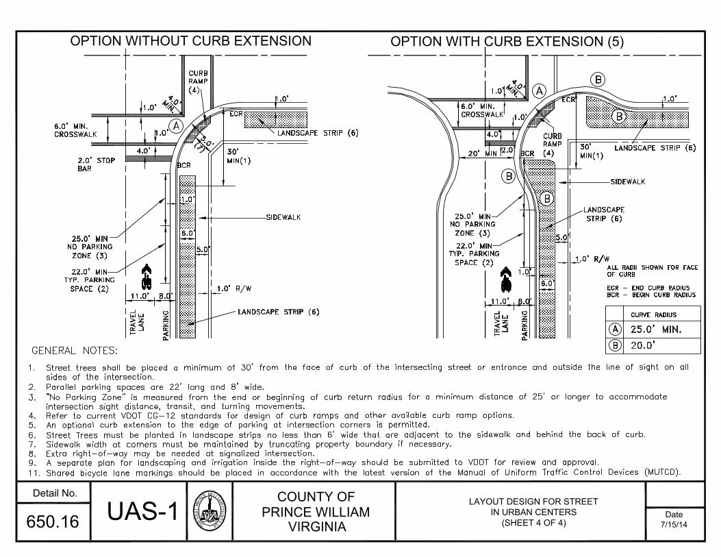
THESEALPRINC
EWILLIAMCOU
NTYVA
COUNTY OFPRINCE WILLIAM
VIRGINIADate
Detail No.
7/15/14650.16
A
BCR
SIDEWALK
B
CURVE RADIUS
25.0' MIN.
20.0'
ECR
BCR
ECR
B
BA
A
SIDEWALK
B
LANDSCAPE STRIP (6)
B
30'
MIN(1)
CURBRAMP
(4)
6.0'
CURBRAMP
(4)30'
MIN(1)
6.0' MIN.CROSSWALK
2.0' STOPBAR
25.0' MINNO PARKING
ZONE (3)
22.0' MINTYP. PARKING
SPACE (2)
ALL RADII SHOWN FOR FACEOF CURB
ECR - END CURB RADIUS
BCR - BEGIN CURB RADIUS8.0'
1.0'
4.0'
LANDSCAPE STRIP (6)
LANDSCAPE STRIP (6)
TR
AV
EL
LAN
E
PA
RK
ING
1.0'
5.0'
25.0' MINNO PARKING
ZONE (3)22.0' MIN
TYP. PARKING
SPACE (2)
1.0' R/W
1. Street trees shall be placed a minimum of 30' from the face of curb of the intersecting street or entrance and outside the line of sight on allsides of the intersection.
2. Parallel parking spaces are 22' long and 8' wide.3. "No Parking Zone" is measured from the end or beginning of curb return radius for a minimum distance of 25' or longer to accommodate
intersection sight distance, transit, and turning movemen ts.
4. Refer to current VDOT CG-12 standards for design of curb ramps and other available curb ramp options.5. An optional curb extension to the edge of parking at intersection corners is permitted.6. Street Trees must be planted in landscape strips no less than 6' wide that are adjacent to the sidewalk and behind the back of curb.7. Sidewalk width at corners must be maintained by truncating property boundary if necessary.8. Extra right-of-way may be needed at signalized intersection.9. A separate plan for landscaping and irrigation inside the right-of-way should be submitted to VDOT for review and approval.11. Shared bicycle lane markings should be placed in accordance with the latest version of the Manual of Uniform Traffic Control Devices (MUTCD).
GENERAL NOTES:
LANDSCAPE
STRIP (6)
5.0'(7)
OPTION WITH CURB EXTENSION (5)OPTION WITHOUT CURB EXTENSION
8.0'
TR
AV
EL
LAN
E
PARK
ING
1.0'
1.0'
4.0'
6.0'
5.0'
1.0' R/W
20' MIN 2.0'
11.0' 11.0'6.0' MIN.CROSSWALK
4.0'
MIN.
4.0'
MIN.LAYOUT DESIGN FOR STREET
IN URBAN CENTERS(SHEET 4 OF 4)
UAS-1
1.0'
1.0'
1.0'
1.0'

COUNTY OF
PRINCE WILLIAMVIRGINIA
Date
Detail No.
7/15/14650.17
SYMMETRICAL
STANDARD TYPICAL SECTION FOR
PRIVATE RESIDENTIAL SIDE STREET
IN URBAN CENTERS
(SHEET 1 OF 2)
UPS-1

COUNTY OF
PRINCE WILLIAMVIRGINIA
Date
Detail No.
7/15/14650.17
PRIVATE SIDE STREET CURB AND
CHOKER LAYOUT DESIGN IN URBAN
CENTERS
(SHEET 2 OF 2)
UPS-1

THESEALPRINC
EWILLIAMCOU
NTYVA
COUNTY OFPRINCE WILLIAM
VIRGINIADate
Detail No.
7/15/14650.18
VARIABLE WIDTH
UTILITY EASEMENT
AS REQUIRED (9)
6"
4'LIMITS OF SUBBASE
1/4":1' 1/4":1'
PL LC
P
P
6"
20' PARKING
STANDARD TYPICAL SECTION FORPRIVATE ALLEY IN URBAN
CENTERS
GENERAL NOTES:
1/4":1' 1/4":1'
(MIN.) FORRESIDENTIAL OPT.
OPTIONALDRAINAGE
TRENCH (8)
6"
OPTIONALDRAINAGE
STRUCTURE (7)CONCRETE
BITUMINOUS
1. This typical cross section shall be used as a 5-10 mph vehicular driveway located to the rear of properties, providing access to parking, servicesareas, rear uses such as secondary units, as well as an easement for utilities in urban centers as defined by Section 601.02 of the DCSM or asotherwise approved by the Director of Transportation.
2. Standard landings required at intersections.3. Pavement section is standard requirement. Refer to Detail 650.01 for alternative pavement sections. Alternative materials such as pervious pavement,
cobblestone, etc. may be allowed subject to approval by the Director of Transportation.4. Private loading and parking access, at least 20' deep, must be located on both sides of the alleyway. (20' for residential uses, 24' for mixed uses)5. Building edges must meet the easement where vehicular access is not necessary.6. Curbs must be flush with street surface.
7. Drainage may flow to center inlet. Alley cross slopes may be modified to eliminate center inlet provided that the drainage design shall insurepositive drainage.
8. An optional 4' wide trench with grass surface can be located on one or both sides of the alleyway. Trench would require driveway crossovers, surfacewater flow to be revised, and an addition of 4' or 8' to the access easement.
9. An optional alley easement for dry utilities (i.e. cable, gas, telephone, and electric) could be located on one side of the alley as an alternative toutility placement under the alley. Variable width utility easement shall be provided only as required.
10. Alley entrances shall conform to VDOT CG-11 standards and VDOT Road Design Manual Appendix B(1), Section B(1)-6.11. Utilities should be located within the travel lane so that manholes and valve covers are not within the typical wheel path area.
4'
OPTIONALDRAINAGE
TRENCH (8)
ACCESS EASEMENT
24' PARKING
(MIN.) FOR MIXEDUSE OPTION
(MIXED USE TRAVELWAY) (RESIDENTIAL TRAVELWAY)
OPTIONALFLUSH
CURB (6)
SUBBASE
UA-1
UP TO 250 20 MIN. 5-10 125120
10%
225 6 in.
P
(ft)10
TRAFFIC VOLUME
(VPD)CATEGORY
ACCESSEASEMENT
WIDTH (ft.)
DESIGNSPEED
(mph)
MAX
GRADE
MIN C.L.RADIUS
(ft.)
MIN. SIGHT
DISTANCE (ft.)STOP INTX
TYPE ISUBBASE
AGG. BASE
(3)
BASE
(BM-25.0A)(3)
SURFACE
(SM-9.5A)(3)(ft) (ft)
PR
P
20 10
2 in.251 TO 400 20 MIN. 5-10 12512010% 225 8 in.10 20 10 2 in.
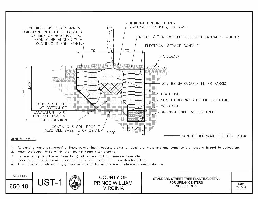
THESEALPRINC
EWILLIAMCOU
NTYVA
COUNTY OFPRINCE WILLIAM
VIRGINIADate
Detail No.
7/15/14650.19 UST-1 STANDARD STREET TREE PLANTING DETAILFOR URBAN CENTERS
SHEET 1 OF 5
GENERAL NOTES
1. At planting prune only crossing limbs, co-dominent leaders, broken or dead branches, and any branches that pose a hazard to pedestrians.2. Water thoroughly twice within the first 48 hours after planting.3. Remove burlap and basket from top 13 of of root ball and remove from site.
4. Sidewalk shall be constructed in accordance with the approved construction plans.5. Tree stabilization stakes or guys are to be installed as per manufacturers recommendations.
4.00
'3.00'
6.00' 1.50'
EQ.EQ.
OPTIONAL GROUND COVER,SEASONAL PLANTINGS, OR GRATE
MULCH (3"-4" DOUBLE SHREDDED HARDWOOD MULCH)
ELECTRICAL SERVICE CONDUIT
SIDEWALK
NON-BIODEGRADABLE FILTER FABRIC
ROOT BALL
NON-BIODEGRADEABLE FILTER FABRIC
AGGREGATE
DRAINAGE PIPE, AS REQUIRED
CONTINUOUS SOIL PROFILEALSO SEE SHEET 2 OF DETAIL
VERTICAL RISER FOR MANUALIRRIGATION. PIPE TO BE LOCATED
ON SIDE OF ROOT BALL 90°FROM CURB ALIGNED WITHCONTINUOUS SOIL PANEL.
NON-BIODEGRADABLE FILTER FABRIC
LOOSEN SUBSOILAT BOTTOM OF
EXCAVATION TO 6"MIN. AND TAMP AT
TREE LOCATION

THESEALPRINC
EWILLIAMCOU
NTYVA
COUNTY OFPRINCE WILLIAM
VIRGINIADate
Detail No.
7/15/14650.19 UST-1 STANDARD STREET TREE PLANTING DETAILFOR URBAN CENTERS
SHEET 2 OF 5
MIN.
3.0'
4.0
0'
1.00'
1.50'
6.00'
SUPPORTED SIDEWALK (SEE NOTESON SHEET 5)
COMPACTED SOIL BASE
CONTINUOUS SOIL PROFILE
(SEE TABLE ON SHEET 5 FORREQUIRED VOLUME IN ORDER
TO DETERMINE THE LENGTH)NON-BIODEGRADABLE FILTERFABRIC
DRAINAGE PIPE, AS REQUIRED
AGGREGATE
MAINTAIN 1:1 BEARING PLANEFROM BASE OF CURB
UNDISTURBED COMPACTED SUBSOIL
NON-BIODEGRADABLE FILTER FABRIC

THESEALPRINC
EWILLIAMCOU
NTYVA
COUNTY OFPRINCE WILLIAM
VIRGINIADate
Detail No.
7/15/14650.19 UST-1 STANDARD STREET TREE PLANTING DETAIL FOR URBANCENTERS
SHEET 3 OF 5
12
OPTIONAL TREE GRATE W/EXPANDABLE CENTER RING
VERTICAL RISER FORMANUAL IRRIGATION
CONTINUOUS UNCOMPACTED SOIL
PANEL UNDER SUSPENDED,REINFORCED SIDEWALK
STANDARD C&G
BACK EDGE OF SIDEWALK
6.0
' CO
NT
.S
OIL
PA
NE
L 1.0'
30' MIN. 30' MIN. (TYP.)8.0'
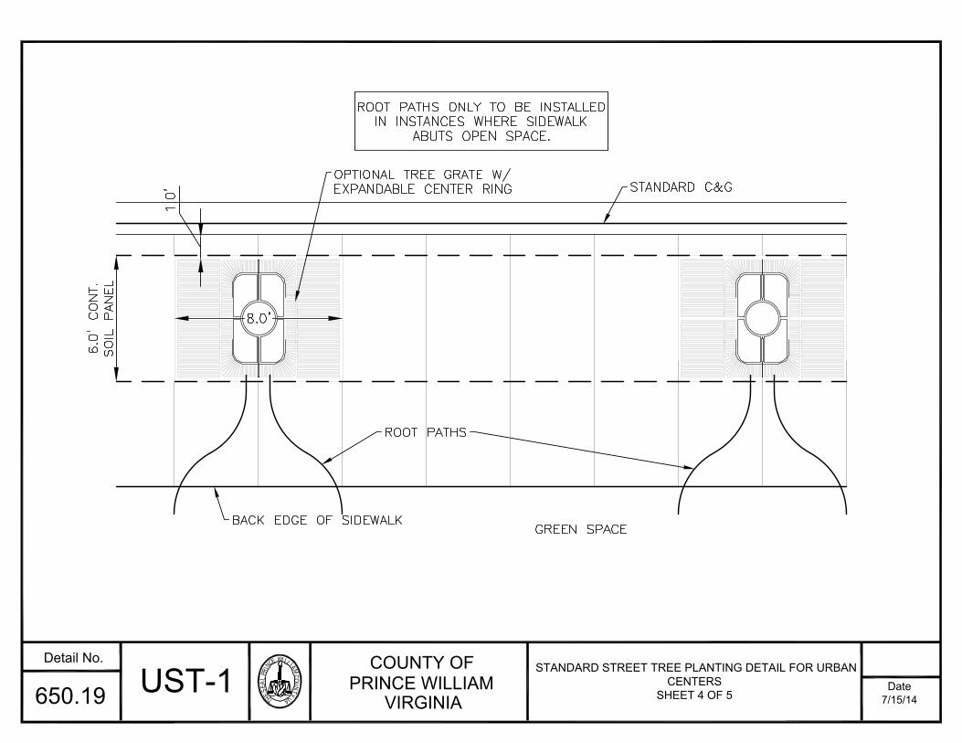
THESEALPRINC
EWILLIAMCOU
NTYVA
COUNTY OFPRINCE WILLIAM
VIRGINIADate
Detail No.
7/15/14650.19 UST-1 STANDARD STREET TREE PLANTING DETAIL FOR URBANCENTERS
SHEET 4 OF 5
GREEN SPACE
ROOT PATHS ONLY TO BE INSTALLED
IN INSTANCES WHERE SIDEWALKABUTS OPEN SPACE.
BACK EDGE OF SIDEWALK
ROOT PATHS
STANDARD C&GOPTIONAL TREE GRATE W/EXPANDABLE CENTER RING
6.0
' CO
NT
.S
OIL
PA
NE
L
1.0
'
8.0'

Tree Size Minimum Volume**Large Street Tree 970 cf
Medium Street Tree 750 cfSmall Street Tree 500 cf
Street Type Street Tree Size*Through Boulevard Large
Boulevard LargeAvenue MediumStreet Medium
Private Residential Side Street SmallPrivate Side Street Small
Private Alley N/A
THESEALPRINC
EWILLIAMCOU
NTYVA
COUNTY OFPRINCE WILLIAM
VIRGINIADate
Detail No.
7/15/14650.19 UST-1 STANDARD STREET TREE PLANTING DETAIL FOR URBANCENTERS
SHEET 5 OF 5
GENERAL NOTES
1. When tree pits and/or landscape strips are used for urban road sections, a continuous soil profile shall be provided for each street tree basedon the required soil volume noted above.
2. Sidewalk over the continuous soil profile must be structurally supported by means that will allow the tree to root within the soil profile. Optionsfor structural support include but are not limited to structural soil, silva cells, and cantilevered sidewalks. The method of support must beapproved by the Prince William County Department of Transportation and the the Department of Public Works prior to construction.
3. The method of support for the sidewalk must provide adequate protection to the tree root zone from compaction that may occur above thetree root zone.
4. Within the VDOT ROW the sidewalk will be maintained by VDOT. However, VDOT nor Prince William County maintain the street trees located withinthe ROW. Maintenance must be provided by others as a condition of plan approval.
5. Trees spaced 30' apart may share volume in one continuous soil profile.6. Storm sewer structures (inlets, manholes, etc.) should not be placed within tree pits. The top of storm sewer pipes shall be under the
continuous soil profile.
**Minimum Volume Based on Table 8-8 of DCSM.
*See DCSM Section 800 Table I-2-T.
NOTE: Variation from these tables
may be permitted subject toapproval by the Prince WilliamCounty Department of Transportationand Department of Public Works.
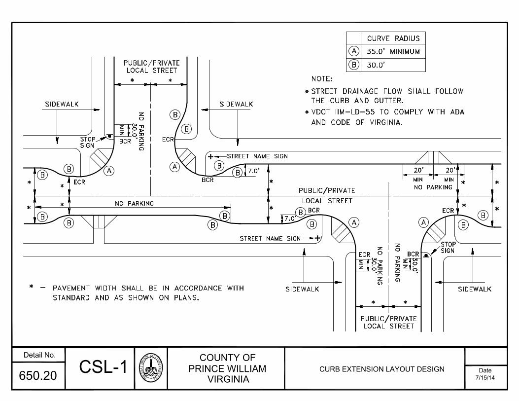
THESEALPRINC
EWILLIAMCOU
NTYVA
COUNTY OFPRINCE WILLIAM
VIRGINIADate
Detail No.
7/15/14650.20
LOCAL STREETPUBLIC/PRIVATE* *
*
*
*
*
LOCAL STREETPUBLIC/PRIVATE
* *
* -
30.0
'
A
MIN
BCRN
O P
AR
KIN
G
SIDEWALK SIDEWALK
SIDEWALK SIDEWALKMIN
BCR
NO
PA
RK
ING
ECR
30.0
'M
INNO PARKING
20'MINNO PARKING
20'
MIN
ECR
B
CURVE RADIUS
35.0' MINIMUM
30.0'
NOTE:
STREET DRAINAGE FLOW SHALL FOLLOW
*
*
** EC
R
NO PARKING
PUBLIC/PRIVATELOCAL STREET
**7.0'
7.0'
PAVEMENT WIDTH SHALL BE IN ACCORDANCE WITH
STANDARD AND AS SHOWN ON PLANS.
BCR
BCR
ECR
BB
BB
B
B
BB
B
BB
B
B
B
AA
A A
30.0
'
THE CURB AND GUTTER.
CSL-1 CURB EXTENSION LAYOUT DESIGN
VDOT IIM-LD-55 TO COMPLY WITH ADA
AND CODE OF VIRGINIA.
STREET NAME SIGN
STREET NAME SIGN
STOPSIGN
STOPSIGN

THESEALPRINC
EWILLIAMCOU
NTYVA
COUNTY OFPRINCE WILLIAM
VIRGINIADate
Detail No.
7/15/14650.21
STD. CG-6
STD. CG-2
MAIN TRAVEL WAY
1) Use pavement Category IV for this street standard.
20.0' GRASS
GENERAL NOTES:
STD. CG-6
STD. CG-6
MIN. SLOPE 1/4":1'1/4":1'1.0'
6"
26.0' SERVICE DRIVE 6.0'
6"
STD. CG-6
STD. SIDEWALK
1/4":1'
1/4":1'STD. CG-2
STD. SIDEWALK
24.0' 2.0'
R/W
1/4":1'1.0'
1/4":1'
L
5.0'
P
1/4":1' MIN. SLOPE 1/4":1'
2) Parking along service drive shall not be allowed.
*3) Wider sidewalk or shared use path may be required by VDOT or County.
SD-1STANDARD TYPICAL STREET SECTION
WITH CURB AND GUTTER FORSERVICE DRIVES
1.0'
(*3)
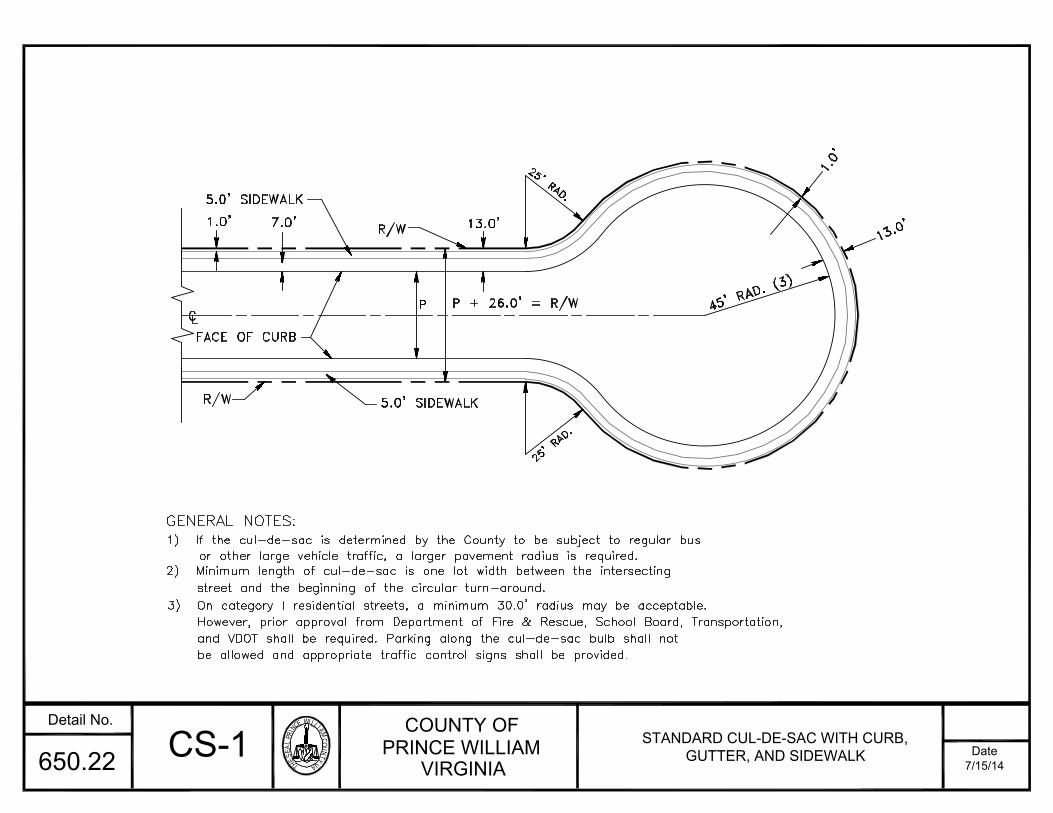
THESEALPRINC
EWILLIAMCOU
NTYVA
COUNTY OFPRINCE WILLIAM
VIRGINIADate
Detail No.
7/15/14650.22
street and the beginning of the circular turn-around.2) Minimum length of cul-de-sac is one lot width between the intersecting
or other large vehicle traffic, a larger pavement radius is required.1) If the cul-de-sac is determined by the County to be subject to regular bus
5.0' SIDEWALK
FACE OF CURB
GENERAL NOTES:
R/W25' RAD.
R/W
5.0' SIDEWALK
7.0
'L
C 1.0
'
P + 26.0' = R/WP
13.0'25' RAD.
13.0'
1.0'
45' RAD. (3)
3) On category I residential streets, a minimum 30.0' radius may be acceptable.However, prior approval from Department of Fire & Rescue, School Board, Transportation,and VDOT shall be required. Parking along the cul-de-sac bulb shall notbe allowed and appropriate traffic control signs shall be provided.
CS-1 STANDARD CUL-DE-SAC WITH CURB,GUTTER, AND SIDEWALK
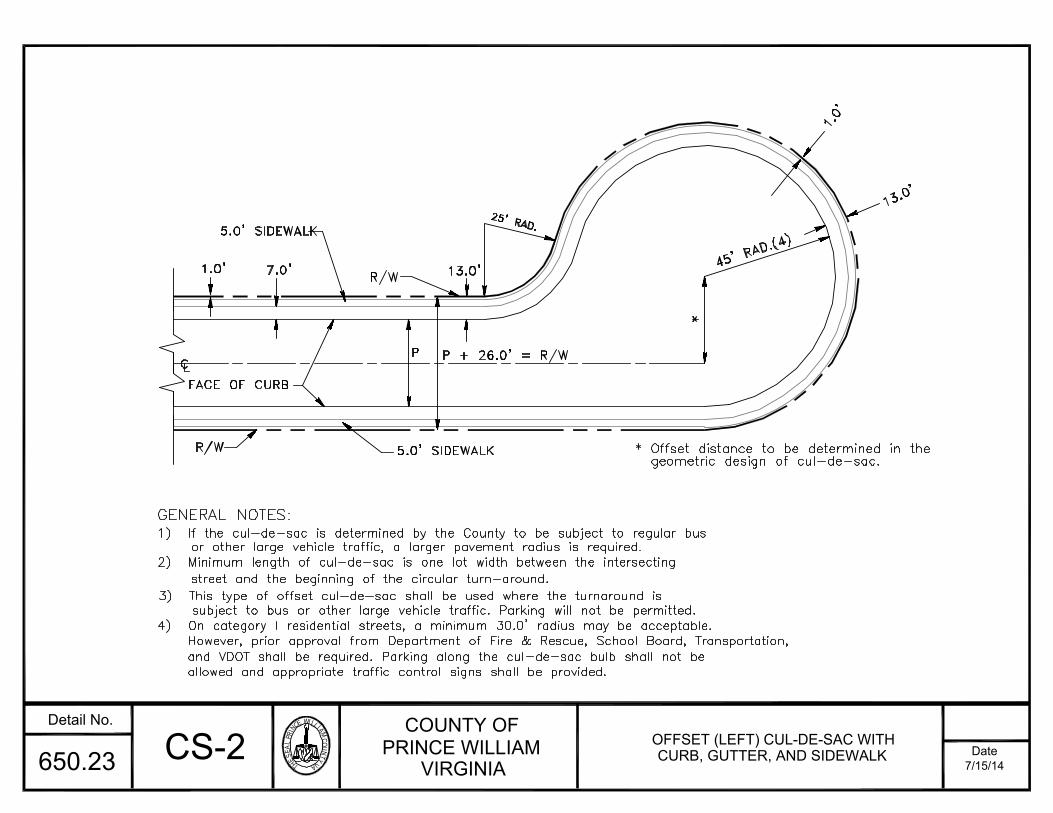
THESEALPRINC
EWILLIAMCOU
NTYVA
COUNTY OFPRINCE WILLIAM
VIRGINIADate
Detail No.
7/15/14650.23
3) This type of offset cul-de-sac shall be used where the turnaround is
2) Minimum length of cul-de-sac is one lot width between the intersecting
1) If the cul-de-sac is determined by the County to be subject to regular busGENERAL NOTES:
subject to bus or other large vehicle traffic. Parking will not be permitted.
street and the beginning of the circular turn-around.
or other large vehicle traffic, a larger pavement radius is required.
FACE OF CURB
R/W
CL5.0' SIDEWALK
P + 26.0' = R/WP
5.0' SIDEWALK1.0
' 7.0' R/W 13.0' 25' RAD. 45' RAD.(4)
1.0'
13.0'
*
* Offset distance to be determined in thegeometric design of cul-de-sac.
4) On category I residential streets, a minimum 30.0' radius may be acceptable.However, prior approval from Department of Fire & Rescue, School Board, Transportation,and VDOT shall be required. Parking along the cul-de-sac bulb shall not beallowed and appropriate traffic control signs shall be provided.
CS-2 OFFSET (LEFT) CUL-DE-SAC WITHCURB, GUTTER, AND SIDEWALK

THESEALPRINC
EWILLIAMCOU
NTYVA
COUNTY OFPRINCE WILLIAM
VIRGINIADate
Detail No.
7/15/14650.24
25' RAD.
3) Design of cul-de-sac should consider counter-clockwise movement on the
2) Minimum length of cul-de-sac is one lot width between the intersecting
1) If the cul-de-sac is determined by the County to be subject to regular bus
GENERAL NOTES:
street and the beginning of the circular turn-around.
or other large vehicle traffic, a larger pavement radius is required.
entry into the offset segment.
5.0' SIDEWALKR/W
FACE OF CURB1.0
'CL 7.0
'
R/WP + 26.0' = R/WP13.0'
1.0'
13.0'
geometric design of cul-de-sac.* Offset to be determined in the
45'RAD.(4)*
4) On category I residential streets, a minimum 30.0' radius may be acceptable.However, prior approval from Department of Fire & Rescue, School Board,Transportation, and VDOT shall be required. Parking along the cul-de-sacbulb shall not be allowed and appropriate traffic control signs shall be provided.
CS-3 OFFSET (RIGHT) CUL-DE-SAC WITHCURB, GUTTER, AND SIDEWALK

THESEALPRINC
EWILLIAMCOU
NTYVA
COUNTY OFPRINCE WILLIAM
VIRGINIADate
Detail No.
7/15/14650.25
NO
R8-1
24" X 30"
CUL-DE-SACON
3) Design of cul-de-sac should consider counter-clockwise movement on the
2) Minimum length of cul-de-sac is one lot width between the intersecting
1) If the cul-de-sac is determined by the County to be subject to regular busGENERAL NOTES:
street and the beginning of the circular turn-around.
or other large vehicle traffic, a larger pavement radius is required.
entry into the offset segment.
FACE OF CURB
R/W
CL P + 26.0' = R/WP
5.0' SIDEWALK
1.0
' 7.0' R/W 13.0' 25' RAD.
geometric design of cul-de-sac.* Offset to be determined in the
5.0'50'RAD.*
126.0' DIA. 20.0'
1.0'
13.0'
7.0'
4) Parking along the cul-de-sac shall not be allowed. Appropriate trafficcontrol (no parking, one-way, and do not enter) signs shall be installed
5) Lots along the cul-de-sac bulb shall be provided with three (3) off-streetparking spaces exclusive of the garage or similar car shelter.
CG-3
prior to occupancy of any unit.
P PARKINGNO
R8-1
24" X 30"
CIRCLEON
CCI-1OFFSET CUL-DE-SAC WITH CURB,
GUTTER, AND SIDEWALK(WITH CENTER ISLAND)
PARKING
MIN
SEE NOTE
1,3,4,&5
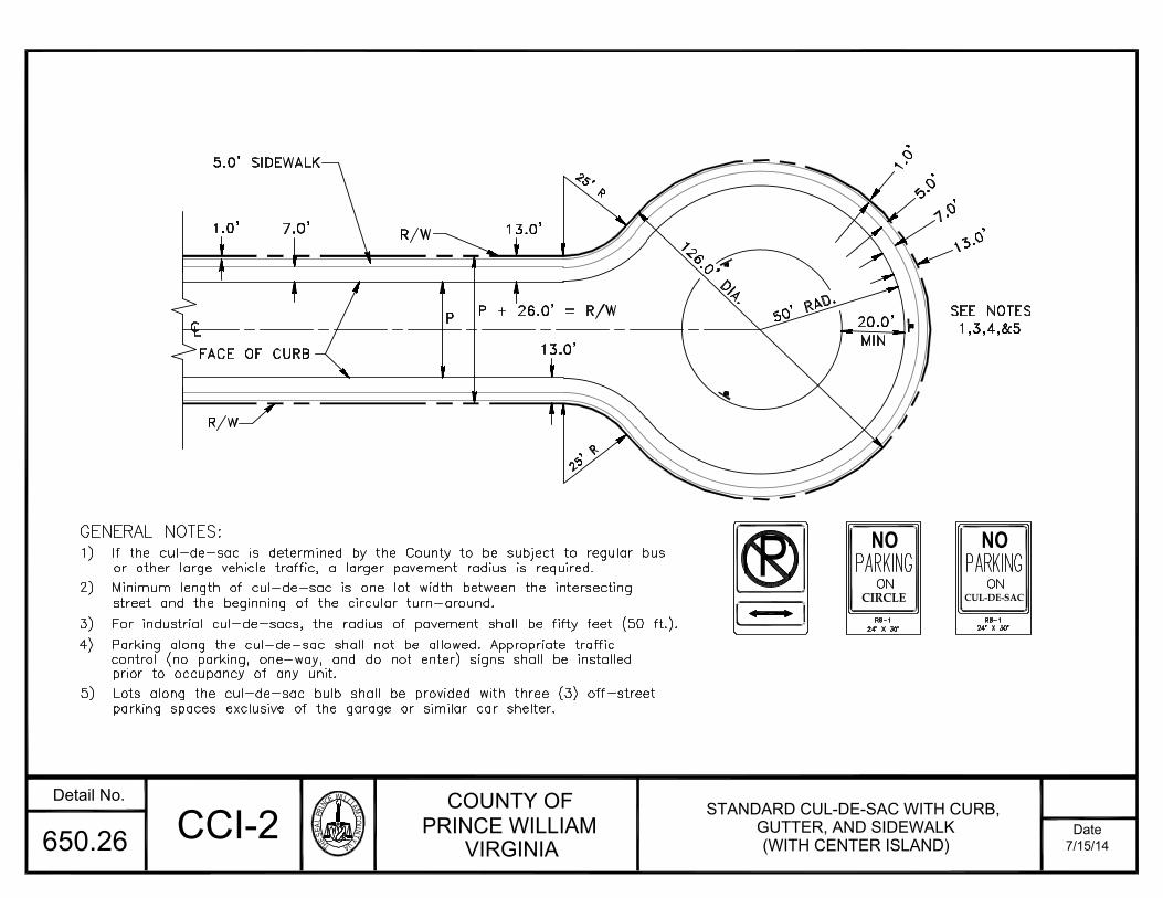
THESEALPRINC
EWILLIAMCOU
NTYVA
COUNTY OFPRINCE WILLIAM
VIRGINIADate
Detail No.
7/15/14650.26
3) For industrial cul-de-sacs, the radius of pavement shall be fifty feet (50 ft.).
2) Minimum length of cul-de-sac is one lot width between the intersecting
1) If the cul-de-sac is determined by the County to be subject to regular busGENERAL NOTES:
street and the beginning of the circular turn-around.
or other large vehicle traffic, a larger pavement radius is required.
FACE OF CURB
R/W 13.0
'
25' R
R/W
5.0' SIDEWALK
7.0
'L
C 1.0
'
P + 26.0' = R/WP13.0'
25' R13.0'
1.0'
50' RAD.126.0' DIA. 7.0'5.0
'
4) Parking along the cul-de-sac shall not be allowed. Appropriate trafficcontrol (no parking, one-way, and do not enter) signs shall be installed
5) Lots along the cul-de-sac bulb shall be provided with three (3) off-streetparking spaces exclusive of the garage or similar car shelter.
prior to occupancy of any unit.
P NO
R8-1
24" X 30"
CUL-DE-SACON
PARKINGNO
R8-1
24" X 30"
CIRCLEON
CCI-2 STANDARD CUL-DE-SAC WITH CURB,GUTTER, AND SIDEWALK(WITH CENTER ISLAND)
PARKING
SEE NOTES
1,3,4,&520.0'MIN
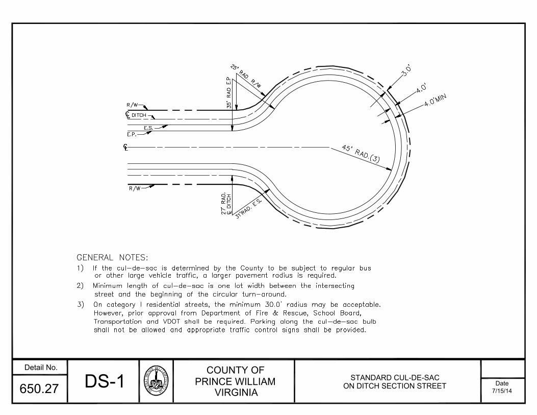
THESEALPRINC
EWILLIAMCOU
NTYVA
COUNTY OFPRINCE WILLIAM
VIRGINIADate
Detail No.
7/15/14650.27
2) Minimum length of cul-de-sac is one lot width between the intersecting
1) If the cul-de-sac is determined by the County to be subject to regular busGENERAL NOTES:
street and the beginning of the circular turn-around.
or other large vehicle traffic, a larger pavement radius is required.
R/W
31'RAD. E.S.C D
ITC
H2
7' R
AD
. L
E.P.
R/WE.S. 35' R
AD
E.P25' RAD. R/W
45' RAD.(3)4.0'MIN4.0
'
3.0'
3) On category I residential streets, the minimum 30.0' radius may be acceptable.However, prior approval from Department of Fire & Rescue, School Board,Transportation and VDOT shall be required. Parking along the cul-de-sac bulbshall not be allowed and appropriate traffic control signs shall be provided.
DS-1 STANDARD CUL-DE-SACON DITCH SECTION STREET
DITCH
LC
LC

THESEALPRINC
EWILLIAMCOU
NTYVA
COUNTY OFPRINCE WILLIAM
VIRGINIADate
Detail No.
7/15/14650.28
LC
3) This type of offset cul-de-sac shall be used where the turnaround is
2) Minimum length of cul-de-sac is one lot width between the intersecting
1) If the cul-de-sac is determined by the County to be subject to regular bus
GENERAL NOTES:
subject to bus or other large vehicle traffic. Parking will not be permitted.
street and the beginning of the circular turn-around.
or other large vehicle traffic, a larger pavement radius is required.
R/W
C DITCHLE.S.E.P.
35' RAD E.P.
25' RAD. R/W
R/W
15'
3.0'
4.0'45' RAD.(4)4.0'MIN*
* Offset distance to be determined in
the geometric design of cul-de-sac.
4) On category I residential streets, a minimum 30.0 radius may be acceptable.However, prior approval from Department of Fire & Rescue, School Board,Transportation and VDOT shall be required. Parking along the cul-de-sacbulb shall not be allowed and appropriate traffic control signs shall be provided.
DS-2 OFFSET (LEFT) CUL-DE-SACON DITCH SECTION STREET

COUNTY OF
PRINCE WILLIAMVIRGINIA
Date
Detail No.
7/15/14650.29 DS-3 OFFSET (RIGHT) CUL-DE-SACON DITCH SECTION STREET

THESEALPRINC
EWILLIAMCOU
NTYVA
COUNTY OFPRINCE WILLIAM
VIRGINIADate
Detail No.
7/15/14650.30
R=50'
PAVING SECTION TO BE SAME AS STREET
PAVING SECTION TO BE SAME AS STREET
GEOMETRICAL SHAPE #2
GEOMETRICAL SHAPE #4
PAVING SECTION TO BE SAME AS STREET
GEOMETRICAL SHAPE #3
MAX.12'R=10'
R=60' R=10'MAX.12'
PAVING SECTION TO BE SAME AS STREET
GEOMETRICAL SHAPE #1
R=15'20'
12'
R=10'
R=10'12'
9.0'
R=10'
60'
9.0'
12'R=10'
9.0'
R=10'
20'
12'
NOTE: ABOVE DESIGNS ARE MINIMUM REQUIREMENTS. DESIGNS CONFORMING TOVDOT'S MINIMUM REQUIREMENTS WHICHEVER IS MORE STRINGENT SHALL BEPROVIDED.
TT-1 TRAVELWAY TURNAROUNDSTANDARDS

THESEALPRINC
EWILLIAMCOU
NTYVA
COUNTY OFPRINCE WILLIAM
VIRGINIADate
Detail No.
7/15/14650.31
4) "No Parking" signs shall be required in the turning area and where required.
private travelway or street exceeds 250 feet measured from the face of curb of the3) The turnarounds (Geometric shapes #1-#3) shall be provided when the length of
2) Geometric shapes shown are guidelines only. Other designs shall requireand single unit trucks for service vehicles.
1) Design based on 40 ft. (Bus) design vehicle for emergency vehicles
GEOMETRIC SHAPE #2
GEOMETRIC SHAPE #4
22'
FOR SERVICE VEHICLESMINIMUM TURNING AREA
20'
R=20' R=20' 30'
70' 30'
22'
prior approval.
GENERAL NOTES:
TRAVELWAY 22' ( MIN.)
GEOMETRIC SHAPE #1
20'R=22'
18'
15'
25'R=50'
45
R=45'
15'10'
(MIN)22'22' (MIN
)15'SPACESPARKING
80'
TRAVELWAY 22' (MIN)
R=34'
GEOMETRIC SHAPE #3
R=34
'
15'
16'
R=6
0'
27'
25'16'
15' 27'
MINIMUM TURNING AREA FOR EMERGENCY VEHICLES
requirements or whichever is more stringent shall be provided.
FOR SERVICE VEHICLES ONLY
TT-2 TRAVELWAY TURNAROUND FOREMERGENCY VEHICLES AND
SERVICE TRUCKS
driveway entrance to the edge of the driveway of the last dwelling unit. Turnaround(Geometric shape #4) shall be required where the length is 100-250 feet.
5) Above designs are minimum requirements. Designs conforming to VDOT's minimum

THESEALPRINC
EWILLIAMCOU
NTYVA
COUNTY OFPRINCE WILLIAM
VIRGINIADate
Detail No.
7/15/14650.32
4) The entrance section of the driveway within
3) For ditch section also refer to detail 650.38
2) Two percent (2%) landing required for first
1) For pavement design refer to Detail 650.01.
GENERAL NOTES:
NUMBER a b c d w
R/W
F.C
.
w
SEE NOTE NO.4
WIDTH OF R/W LINE
7.0'
R/W
5.0' S/W
c
13.0'
a
WIDTH OF PAVEMENT
LC
b
WIDTH OF EASEMENT
with curb and gutter standard DE-2 orin accordance with the alternative entrancethe right-of-way limits should be designed
CG-9D standard of VDOT.
for DE-4.
twenty (20) feet.
(ft)
2-5 40 18 12 24 28
1 18 10 STD. DE-2
LOTS
OF (ft) (ft) (ft) (ft)
5.0' S/W 1.0'
d
PP-1 PIPESTEM ENTRANCE DESIGNWITH CURB AND GUTTER
5) Design of entrance apron shall conform to Countyor VDOT requirements whichever is more stringent.
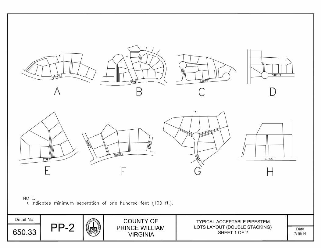
THESEALPRINC
EWILLIAMCOU
NTYVA
COUNTY OFPRINCE WILLIAM
VIRGINIADate
Detail No.
7/15/14650.33
Indicates minimum seperation of one hundred feet (100 ft.).NOTE:*
E
STREETSTREET
F
STRE
ETSTREET
ASTREET* BSTREET*
STREET
HG
STREET
*C
STREETSTRE
ET
DSTREET
TYPICAL ACCEPTABLE PIPESTEMLOTS LAYOUT (DOUBLE STACKING)
SHEET 1 OF 2PP-2
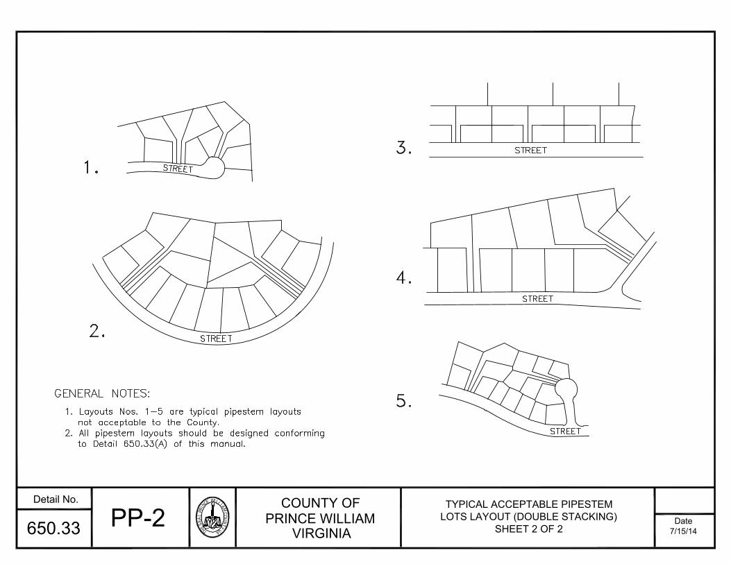
THESEALPRINC
EWILLIAMCOU
NTYVA
COUNTY OFPRINCE WILLIAM
VIRGINIADate
Detail No.
7/15/14
1. Layouts Nos. 1-5 are typical pipestem layouts
GENERAL NOTES:
1.
STREET
STREETSTREET
2.
3.
4.
STREET5.
not acceptable to the County.2. All pipestem layouts should be designed conforming
to Detail 650.33(A) of this manual.
STREET
PP-2TYPICAL ACCEPTABLE PIPESTEM
LOTS LAYOUT (DOUBLE STACKING)SHEET 2 OF 2650.33
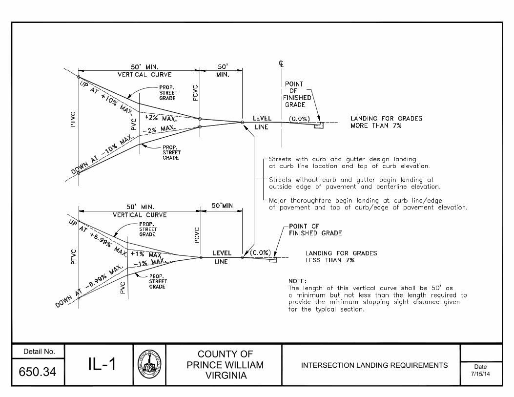
THESEALPRINC
EWILLIAMCOU
NTYVA
COUNTY OFPRINCE WILLIAM
VIRGINIADate
Detail No.
7/15/14650.34
for the typical section.provide the minimum stopping sight distance givena minimum but not less than the length required toThe length of this vertical curve shall be 50' as
of pavement and top of curb/edge of pavement elevation.Major thoroughfare begin landing at curb line/edge
outside edge of pavement and centerline elevation.Streets without curb and gutter begin landing at
at curb line location and top of curb elevation.Streets with curb and gutter design landing
LANDING FOR GRADESLESS THAN 7%
DOWN AT -6.99% MAX.PVC PROP.STREETGRADE
VERTICAL CURVEUP AT +6.99% MAX.
PTVC
GRADESTREET
+1% MAX
PROP.
50' MIN.
NOTE:
(0.0%)
POINT OF
FINISHED GRADELEVEL
PCVC
LINE
UP AT +10% MAX.
DOWN AT -10% MAX.
PT
VC
PROP.STREETGRADE
-2% MAX.
+2% MAX.
PV
C
VERTICAL CURVE50' MIN.
PROP.STREETGRADE GRADELINE
LEVEL (0.0%)
50'
MIN.
PCVC
L
POINT
FINISHEDOF
C
MORE THAN 7%LANDING FOR GRADES
IL-1 INTERSECTION LANDING REQUIREMENTS
50'MIN
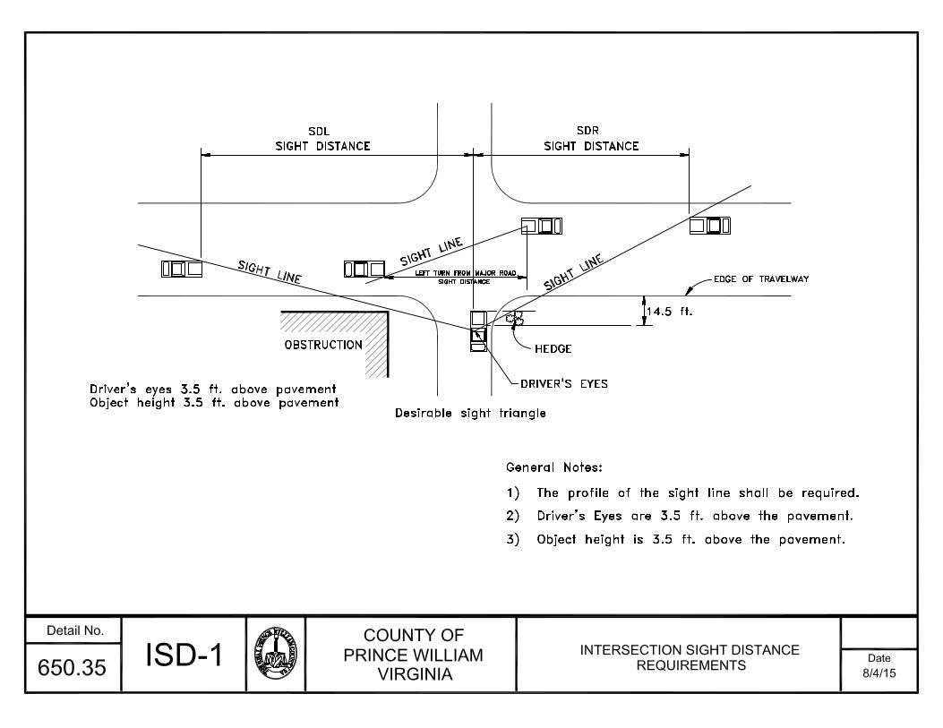

THESEALPRINC
EWILLIAMCOU
NTYVA
COUNTY OFPRINCE WILLIAM
VIRGINIADate
Detail No.
7/15/14650.36
12) For Design, Drainage, and other Specifications not in this manual, refer to current VDOT Standards and/or AASHTO Manual for the
11) Standard UD-3 shall be used when the longitudinal gradient is three percent (3%) or more and when the underlying soil has 34% or10) Base layer (21A or 21B) shall be primed with liquid asphalt at 0.4 gals/s.y. in accordance with VDOT I&II LD - 91(D) 157.3.9) Profile shall be shown on plans when required by the Department of Public Works.8) A side slope of 2:1 will be allowed where special stabilization is provided in accordance with the Erosion Control ordinance.7) Superelevation shall be used on all curves following the rates specified in the above table.
5) Pavement cross-slope of 1/4 in.:1 ft. required. Pavement surface may be crowned in the middle or sloped to one side.
- 2 percent for length up to 1500 feet
- 10 percent for length up to 100 feet1) Maximum grades must conform to maximum allowed street grades. Minor variations from the following may be permitted with approval:
AGGREGATE 21A OR 21B
ASPHALT SM-9.5A
FIRMLY COMPACTED
development of bicycle facilities.
more passing the Number 200 sieve and has a P.I. of 13 or less.
6) Maximum design speed shall be 25 MPH.
4) Minimum vertical clearance of ten feet (10').3) Minimum horizontal clearance of fourteen feet (14.0') total.2) Minimum horizontal radius of curvature is fifteen feet (15').
GENERAL NOTES:
- 5 percent for length up to 300 feet
3:1 SLOPE5/8":1'
6"
(8)
SUBGRADE
2.0'
3:1 SLOPE6"
5/8":1'
10.0' 2.0'
(8)6"
2"
DESIGN SPEED - VMINIMUM RADII FOR PAVED BICYCLE PATHS(mph)
25
20
(feet)MINIMUM RADIUS - R
FRICTION FACTOR - F
e = 2% (Percent) minimum
0.250.27
155
100
BT-1BICYCLE TRAIL/SHARED USE PATH
STANDARDSFOR VDOT MAINTENANCE
2"
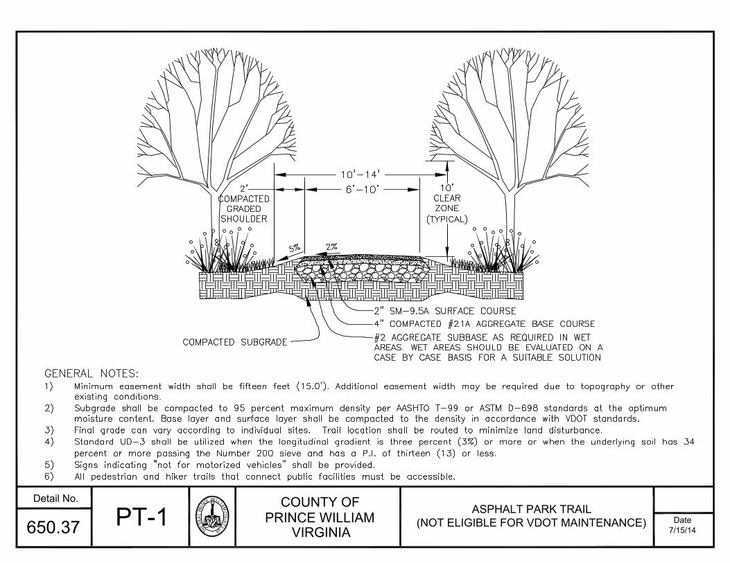
THESEALPRINC
EWILLIAMCOU
NTYVA
COUNTY OFPRINCE WILLIAM
VIRGINIADate
Detail No.
7/15/14650.37 PT-1 ASPHALT PARK TRAIL(NOT ELIGIBLE FOR VDOT MAINTENANCE)
6'-10'
5% 2%
2'COMPACTED
GRADEDSHOULDER2" SM-9.5A SURFACE COURSE
4" COMPACTED #21A AGGREGATE BASE COURSE
COMPACTED SUBGRADE #2 AGGREGATE SUBBASE AS REQUIRED IN WETAREAS. WET AREAS SHOULD BE EVALUATED ON A
CASE BY CASE BASIS FOR A SUITABLE SOLUTION
10'-14'
GENERAL NOTES:
1) Minimum easement width shall be fifteen feet (15.0'). Additional easement width may be required due to topography or otherexisting conditions.
2) Subgrade shall be compacted to 95 percent maximum density per AASHTO T-99 or ASTM D-698 standards at the optimummoisture content. Base layer and surface layer shall be compacted to the density in accordance with VDOT standards.
3) Final grade can vary according to individual sites. Trail location shall be routed to minimize land disturbance.4) Standard UD-3 shall be utilized when the longitudinal gradient is three percent (3%) or more or when the underlying soil has 34
percent or more passing the Number 200 sieve and has a P.I. of thirteen (13) or less.5) Signs indicating "not for motorized vehicles" shall be provided.6) All pedestrian and hiker trails that connect public facilities must be accessible.
10'CLEAR
ZONE
(TYPICAL)
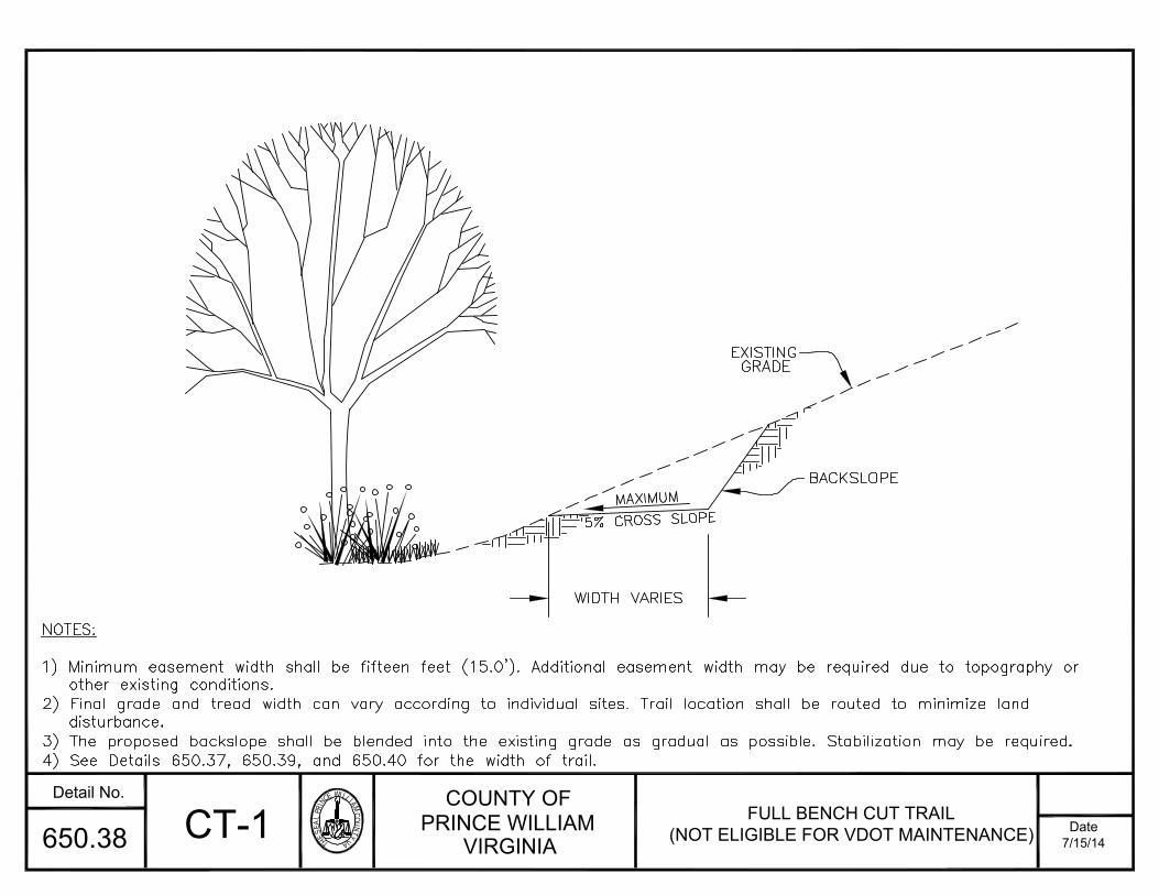
THESEALPRINC
EWILLIAMCOU
NTYVA
COUNTY OFPRINCE WILLIAM
VIRGINIADate
Detail No.
7/15/14650.38 CT-1 FULL BENCH CUT TRAIL(NOT ELIGIBLE FOR VDOT MAINTENANCE)
NOTES:
1) Minimum easement width shall be fifteen feet (15.0'). Additional easement width may be required due to topography orother existing conditions.
2) Final grade and tread width can vary according to individual sites. Trail location shall be routed to minimize landdisturbance.
3) The proposed backslope shall be blended into the existing grade as gradual as possible. Stabilization may be required.4) See Details 650.37, 650.39, and 650.40 for the width of trail.
MAXIMUM
5% CROSS SLOPE
WIDTH VARIES
EXISTINGGRADE
BACKSLOPE
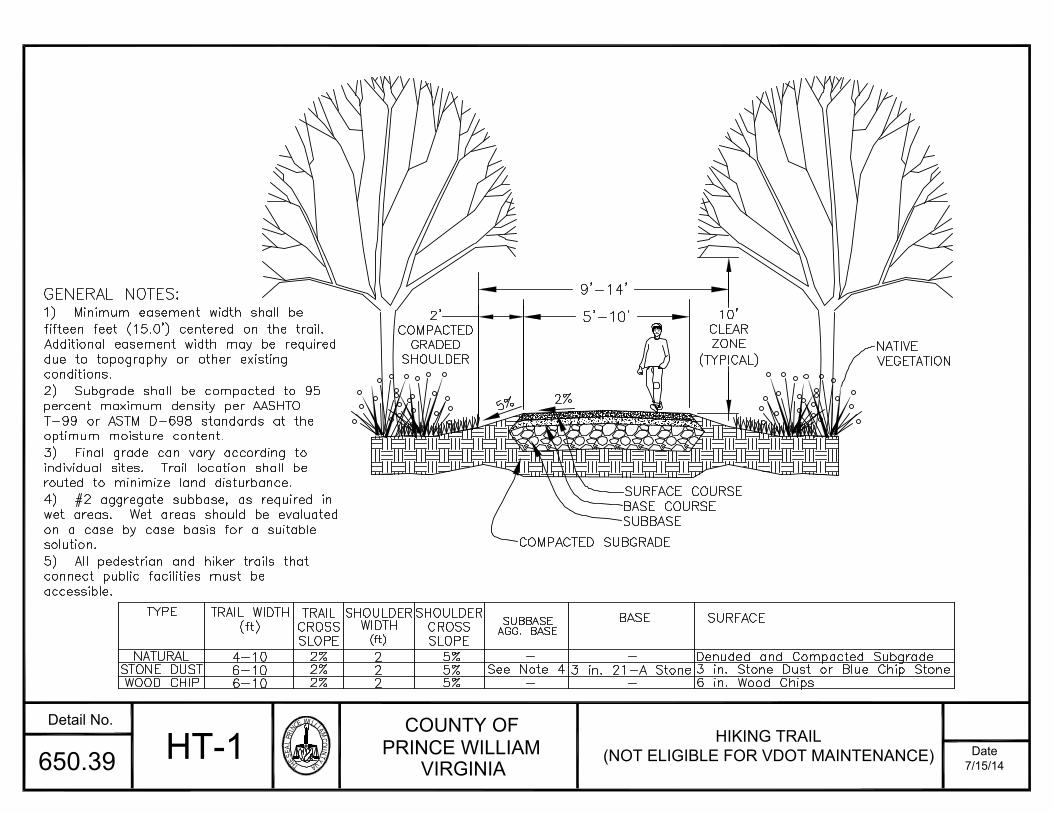
THESEALPRINC
EWILLIAMCOU
NTYVA
COUNTY OFPRINCE WILLIAM
VIRGINIADate
Detail No.
7/15/14650.39 HT-1 HIKING TRAIL(NOT ELIGIBLE FOR VDOT MAINTENANCE)
5'-10'
5% 2%
2'COMPACTED
GRADEDSHOULDER NATIVEVEGETATION
SURFACE COURSE
BASE COURSE
COMPACTED SUBGRADE
SUBBASE
9'-14'
SHOULDERTRAILTRAIL WIDTHTYPE
WOOD CHIPSTONE DUST
NATURAL(ft)
WIDTH
6-106-104-10
(ft)
2%
CROSS
2 5%
BASE
3 in. 21-A StoneSee Note 4
AGG. BASESUBBASE SURFACE
SLOPE
2%2% 6 in. Wood Chips
3 in. Stone Dust or Blue Chip StoneDenuded and Compacted Subgrade
22
SHOULDERCROSSSLOPE
5%5%
GENERAL NOTES:
1) Minimum easement width shall befifteen feet (15.0') centered on the trail.Additional easement width may be requireddue to topography or other existingconditions.
2) Subgrade shall be compacted to 95percent maximum density per AASHTOT-99 or ASTM D-698 standards at the
optimum moisture content.3) Final grade can vary according toindividual sites. Trail location shall berouted to minimize land disturbance.
4) #2 aggregate subbase, as required inwet areas. Wet areas should be evaluated
on a case by case basis for a suitablesolution.
5) All pedestrian and hiker trails thatconnect public facilities must beaccessible.
10'CLEARZONE
(TYPICAL)

THESEALPRINC
EWILLIAMCOU
NTYVA
COUNTY OFPRINCE WILLIAM
VIRGINIADate
Detail No.
7/15/14650.40 ET-1 EQUESTRIAN TRAIL(NOT ELIGIBLE FOR VDOT MAINTENANCE)
10'
12'CLEARZONE
(TYPICAL)
5% 2%
3'
CLEAR
ZONE(TYPICAL) NATIVEVEGETATION
SURFACE COURSE
COMPACTED SUBGRADE
SUBBASE
5'
BASE COURSE
SHOULDERTRAILTRAIL WIDTHTYPE
STONE DUSTNATURAL
(ft)WIDTH
10
10
(ft)
2%
CROSS
3 5%
BASE
2 in. 21-A StoneSee Note #4
AGG. BASESUBBASE SURFACE
SLOPE
2% 2 in. Stone Dust or Blue Chip StoneDenuded and Compacted Subgrade
3
SHOULDERCROSSSLOPE
5%
GENERAL NOTES:
1) Minimum easement width shall befifteen feet (15.0'). Additional easementwidth may be required due to topographyor other existing conditions.2) Subgrade shall be compacted to 95percent maximum density per AASHTOT-99 or ASTM D-698 standards at the
optimum moisture content.3) Final grade can vary according toindividual sites. Trail location shall be
routed to minimize land disturbance.
4) #2 aggregate subbase, as required inwet areas. Wet areas should be evaluated
on a case by case basis for a suitablesolution.
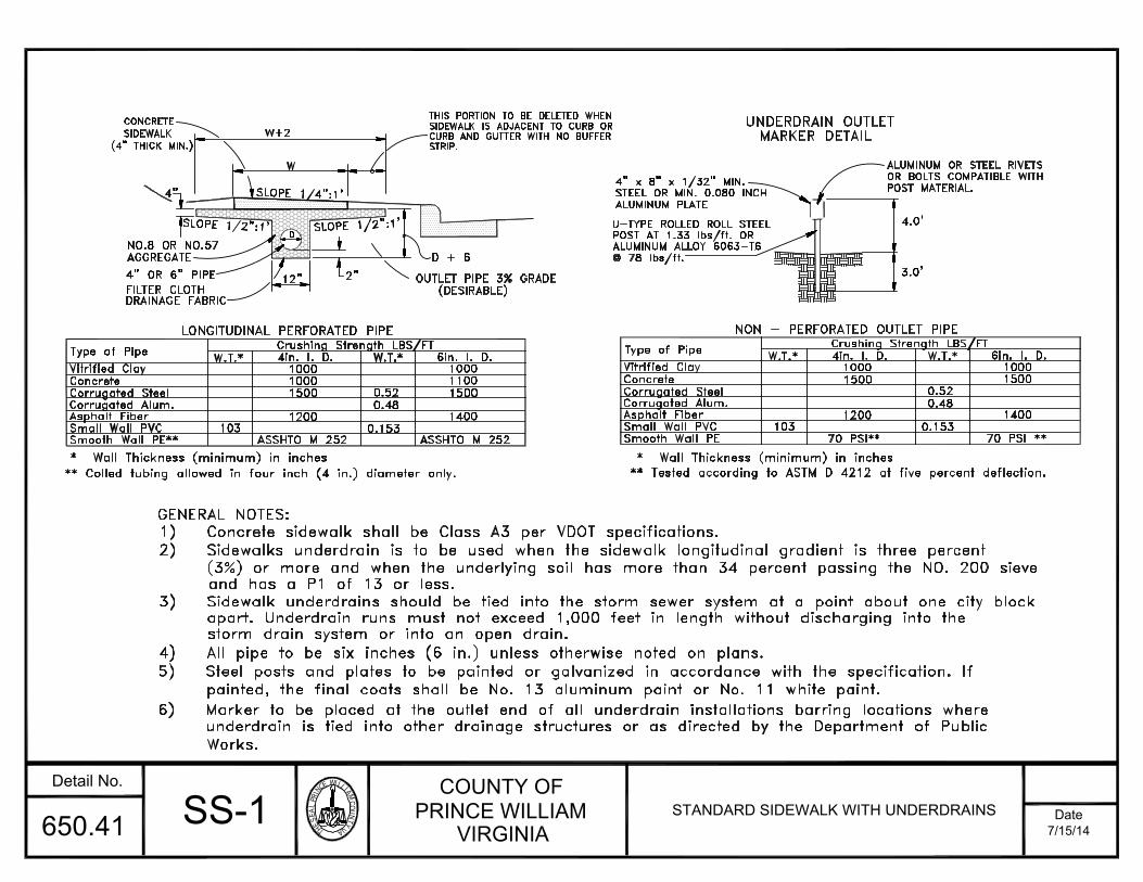
THESEALPRINC
EWILLIAMCOU
NTYVA
COUNTY OFPRINCE WILLIAM
VIRGINIADate
Detail No.
7/15/14650.41
ALUMINUM ALLOY 6063-T6
U-TYPE ROLLED ROLL STEEL
STEEL OR MIN. 0.080 INCH4" x 8" x 1/32" MIN.
underdrain is tied into other drainage structures or as directed by the Department of Public6) Marker to be placed at the outlet end of all underdrain installations barring locations where
painted, the final coats shall be No. 13 aluminum paint or No. 11 white paint.5) Steel posts and plates to be painted or galvanized in accordance with the specification. If
apart. Underdrain runs must not exceed 1,000 feet in length without discharging into the3) Sidewalk underdrains should be tied into the storm sewer system at a point about one city block
2) Sidewalks underdrain is to be used when the sidewalk longitudinal gradient is three percent1) Concrete sidewalk shall be Class A3 per VDOT specifications.
4) All pipe to be six inches (6 in.) unless otherwise noted on plans.
GENERAL NOTES:
storm drain system or into an open drain.
Works.
and has a P1 of 13 or less.
6" PIPE4" OR
AGGREGATENO.8 OR NO.57
(4" THICK MIN.)SIDEWALK
CONCRETE
4"
SLOPE 1/2":1'SLOPE 1/2":1'FILTER CLOTHDRAINAGE FABRIC
12"D
2"
W+2SLOPE 1/4":1'W
OUTLET PIPE 3% GRADE(DESIRABLE)
D + 6
CURB AND GUTTER WITH NO BUFFERSIDEWALK IS ADJACENT TO CURB ORTHIS PORTION TO BE DELETED WHEN
STRIP.
ALUMINUM PLATE
POST MATERIAL.OR BOLTS COMPATIBLE WITHALUMINUM OR STEEL RIVETS
3.0'
MARKER DETAILUNDERDRAIN OUTLET
4.0'
Vitrified ClayType of Pipe
Concrete
Corrugated SteelCorrugated Alum.Asphalt FiberSmall Wall PVC
Smooth Wall PE**
Crushing Strength LBS/FTLONGITUDINAL PERFORATED PIPEW.T.* 4in. I. D. W.T.* 6in. I. D.
100010001500
1200
ASSHTO M 252103
0.52
0.153
0.48
100011001500
1400
ASSHTO M 252
* Wall Thickness (minimum) in inches** Colled tubing allowed in four inch (4 in.) diameter only.
POST AT 1.33 lbs/ft. OR@ 78 lbs/ft.
0.521500Corrugated Steel
70 PSI**
** Tested according to ASTM D 4212 at five percent deflection.* Wall Thickness (minimum) in inches
Corrugated Alum.Asphalt FiberSmall Wall PVCSmooth Wall PE
1031200 1400
70 PSI **
0.48
0.153
Crushing Strength LBS/FT4in. I. D.
NON - PERFORATED OUTLET PIPE
Vitrified Clay
Type of Pipe
Concrete
W.T.*1000
15001000
6in. I. D.W.T.*
SS-1 STANDARD SIDEWALK WITH UNDERDRAINS
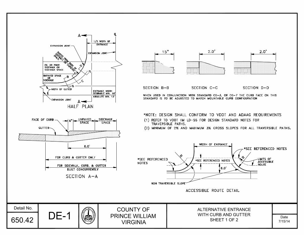
THESEALPRINC
EWILLIAMCOU
NTYVA
COUNTY OFPRINCE WILLIAM
VIRGINIADate
Detail No.
7/15/14650.42
STANDARD IS TO BE ADJUSTED TO MATCH MOUNTABLE CURB CONFIGURATIONWHEN USED IN CONJUNCTION WITH STANDARD CG-3, OR CG-7 THE CURB FACE ON THIS
SECTION B-B SECTION C-C SECTION D-D
NON TRAVERSIBLE SLOPE
FOR SIDEWALK, CURB, & GUTTERSECTION A-A
FOR CURB & GUTTER ONLYBUILT CONCURRENTLY
FACE OF CURB
GUTTER
6.0'
SPACE
UNPAVED
6"SPACE
SIDEWALK
R
SIDEWALK OR UNPAVEDRADIUS FROM BACK OF
HALF PLAN
B
EXPANSION JOINTWIDTH OF GUTTER
SIDEWALK SPACE
EX. OR PROP.
UNPAVED SPACE
SIDEWALKOR
SIDEWALK OR
C
B
C
D
D
EXPANSION JOINT
SPACEEXPANSION JOINT
ENTRANCE1/2 WIDTH OF
LC
15"
ACCESSIBLE ROUTE DETAIL6.0'
WIDTH OF ENTRANCE
R ACCESSIBLEROUTE
LIMITS OF
2.0' 2.0'
ENTRANCE WIDTHDESIRABLE MIN. 16'
ABSOLUTE MIN. 12'
AA
*NOTE: DESIGN SHALL CONFORM TO VDOT AND ADAAG REQUIREMENTS
DE-1ALTERNATIVE ENTRANCEWITH CURB AND GUTTER
SHEET 1 OF 2
(1) REFER TO VDOT IIM LD-55 FOR DESIGN STANDARD NOTES FORTRAVERSIBLE PATHS.
(2) MINIMUM OF 2% AND MAXIMUM 3% CROSS SLOPES FOR ALL TRAVERSIBLE PATHS.
*SEE REFERENCED NOTES
*SEE REFERENCED
NOTES*SEE REFERENCED NOTES
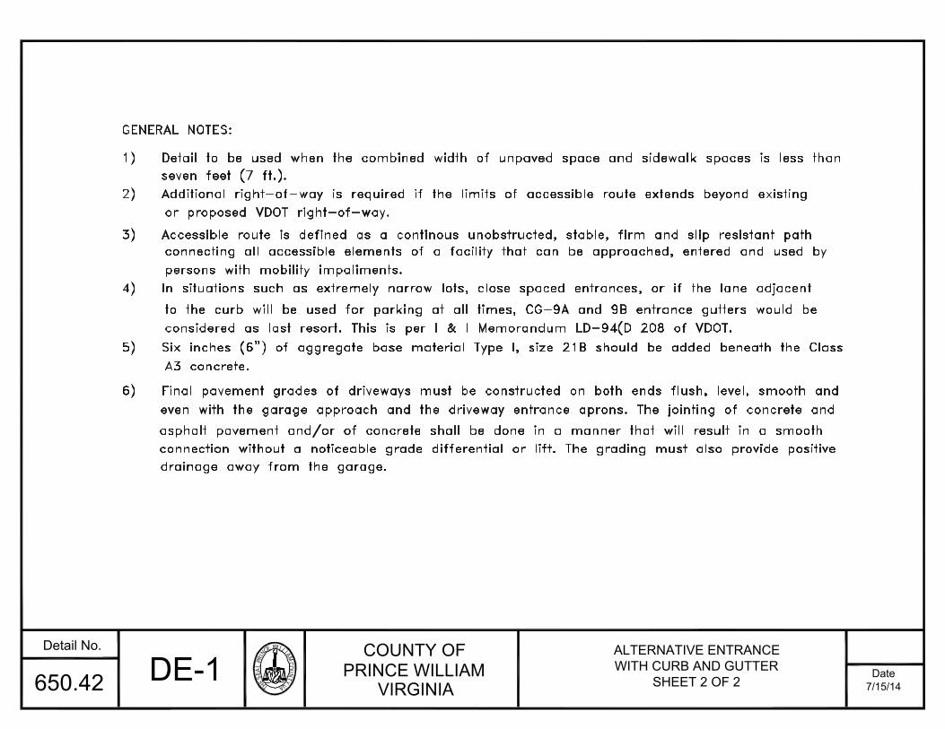
THESEALPRINC
EWILLIAMCOU
NTYVA
COUNTY OFPRINCE WILLIAM
VIRGINIADate
Detail No.
7/15/14650.42
5) Six inches (6") of aggregate base material Type I, size 21B should be added beneath the Classconsidered as last resort. This is per I & I Memorandum LD-94(D 208 of VDOT.to the curb will be used for parking at all times, CG-9A and 9B entrance gutters would be
4) In situations such as extremely narrow lots, close spaced entrances, or if the lane adjacent
connecting all accessible elements of a facility that can be approached, entered and used by3) Accessible route is defined as a continous unobstructed, stable, firm and slip resistant path
2) Additional right-of-way is required if the limits of accessible route extends beyond existing
1) Detail to be used when the combined width of unpaved space and sidewalk spaces is less than
GENERAL NOTES:
persons with mobility impaliments.
A3 concrete.
or proposed VDOT right-of-way.
seven feet (7 ft.).
6) Final pavement grades of driveways must be constructed on both ends flush, level, smooth andeven with the garage approach and the driveway entrance aprons. The jointing of concrete and
asphalt pavement and/or of concrete shall be done in a manner that will result in a smoothconnection without a noticeable grade differential or lift. The grading must also provide positivedrainage away from the garage.
DE-1ALTERNATIVE ENTRANCEWITH CURB AND GUTTER
SHEET 2 OF 2

THESEALPRINC
EWILLIAMCOU
NTYVA
COUNTY OFPRINCE WILLIAM
VIRGINIADate
Detail No.
7/15/14650.43
4) Six inches (6") of aggregate base material type I, size 21B should be added beneath the class A3 concrete.
with the garage and the length or depth is less than 40 ft. measured from the right of way to the garage.double garage dwelling units and where the lot frontage is less than 70'. The driveway is to be aligned
2) The driveway entrance widths shown are to be used on RPC, R-4C, R-4, R-2, and PMR zoning districts with1) For streets without sidewalk, the entrance apron may be constructed 2.5 feet beyond the back of the curb.
CONSTRUCTION
3) Slip forms will be allowed initially in the construction of CG-6.
GENERAL NOTES:
16.0' (MIN.)22.0' (SEE NOTE #2) JOINTS
F.C.
OPTIONAL
JOINT FILLER *1/2" EXPANSION
6" JOINT
1.0'SCORED SEE NOTE #1
R/W
18.0' (see note 2)12.0'(MIN)
SPACE2.0'
UNPAVED5.0'SIDEWALK
ACCESSIBLE ROUTELIMIT OF
SIDEWALK TO BE EXTENDED AS SHOWN.IF ACCESSIBLE ROUTE IS REQUIRED,
#5 DOWELS x 8" LONG @ 12" O.C.
0% - 2%
SIDEWALK5.0'
COMPACTED SUBGRADE
7"
CG-6 12:1 MAX
2.0'
AREATRANSITIONR/W
5) Final pavement grades of driveways must be constructed on both ends flush, level, smooth and even with thegarage approach and the driveway entrance aprons. The jointing of concrete and asphalt pavement and/or ofconcrete shall be done in a manner that will result in a smooth connection without a noticeable grade differential
10.0'MIN
DE-2 DRIVEWAY ENTRANCEWITH CURB AND GUTTER
(SINGLE FAMILY DETACHED)
1.0'
1.0'
(1) REFER TO VDOT IIM LD-55.15 FOR DESIGN STANDARD NOTESFOR TRAVERSIBLE PATHS.
(2) MINIMUM OF 2% AND MAXIMUM 3% CROSS SLOPES FOR
*NOTES:
*SEE
REFERENCEDNOTES
*SEEREFERENCEDNOTES
FOR ALL TRAVERSIBLE PATHS.
or lift. The grading must also provide positive drainage away from the garage.6) Design shall conform to VDOT and ADAAG requirements.
1.0' MINIMUM
TRANSITION
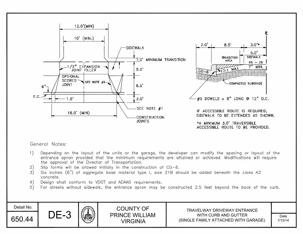
THESEALPRINC
EWILLIAMCOU
NTYVA
COUNTY OFPRINCE WILLIAM
VIRGINIADate
Detail No.
7/15/14650.44
SEE NOTE #1
General Notes:
16.0' (MIN)CONSTRUCTION
JOINTS
6"
F.C.
OPTIONAL
JOINT FILLER1/2" EXPANSIONJOINT
1.0'SCOREDSEE NOTE #5
10' (MIN.)
6.5'2.0'5.0'
SIDEWALK
ACCESSIBLE ROUTE TO BE PROVIDED.*A MINIMUM 3.0' TRAVERSIBLE
SIDEWALK TO BE EXTENDED AS SHOWN.IF ACCESSIBLE ROUTE IS REQUIRED,
#5 DOWELS x 8" LONG @ 12" O.C.
3.0'*
5.0'
0% - 2%
COMPACTED SUBGRADE
7" MIN.CG-6 12:1 MAX
2.0'
AREATRANSITION
8.5'LP
SIDEWALK
DE-3 TRAVELWAY DRIVEWAY ENTRANCEWITH CURB AND GUTTER
(SINGLE FAMILY ATTACHED WITH GARAGE)
12.0'(MIN)
1.0' MINIMUM TRANSITION
1) Depending on the layout of the units or the garage, the developer can modify the spacing or layout of theentrance apron provided that the minimum requirements are attained or achieved. Modifications will requirethe approval of the Director of Transportation.
2) Slip forms will be allowed initially in the construction of CG-6.3) Six inches (6") of aggregate base material type I, size 21B should be added beneath the class A3
concrete.
4) Design shall conform to VDOT and ADAAG requirements.5) For streets without sidewalk, the entrance apron may be constructed 2.5 feet beyond the back of the curb.

THESEALPRINC
EWILLIAMCOU
NTYVA
COUNTY OFPRINCE WILLIAM
VIRGINIADate
Detail No.
7/15/14650.45
DRIVEWAY CULVERT PIPE INSTALLATION
6"
3:1 SLOPE
9" MIN. STONECOVER OVER PIPE
COVER OVER PIPE
9" MIN. STONE
erosion and sedimentation control ordinance.stablization is provided in accordance with2:1 slopes will be allowed where special
and runoff velocities will cause erosion.A paved ditch is required where soil conditions
WITH PAVED ROADSIDE DITCH
36.0'LOW POINT
CL L
EDGE OF PAVEMENT
EDGE OF SHOULDER
C
CONCRETE IF APPLICABLEAGGREGATE (MIN.) OR 5"2" SM-9.5A AND 6' OFTO R/W LINE SHALL BETHE PAVEMENT STRUCTURE
IS GREATERIS DISTURBED WHICHEVERLINE OR AS FAR AS GROUND9"STONE SURFACE TO R/W
GR
AD
E A
ND
SU
RF
AC
ED
SLO
PE
COVER OVER PIPECOLLAR TO MINIMUMCONCRETE OR ASPHALT
R/W
IF NECESSARYPIPE CULVERT
C OF DITCHR/W12.0'L
12.0'
10.0'
6"x 6" WIRE MESH
6"
SHOULDER SLOPE
WITH PAVED ROADSIDE DITCH
DRIVEWAYLOW POINT
1.0'(MIN)
SHOULDER SLOPEDRIVEWAYWITH UNPAVED ROADSIDE DITCH
3:1 SLOPE 4:1 SLOPE
4.0' (min.)
LOW POINT
OR AS NOTED ABOVE.
NOTE: Design shall conform to County or VDOTrequirements whichever is more stringent.
4.0' (min.)
DE-4DRIVEWAY ENTRANCEWITH DITCH SECTION
SHEET 1 OF 2
DEPTH REQUIREDOR MIN PAVEMENT
FOR THE ROAD.
DEPTH REQUIREDOR MIN. PAVEMENT
FOR THE ROAD
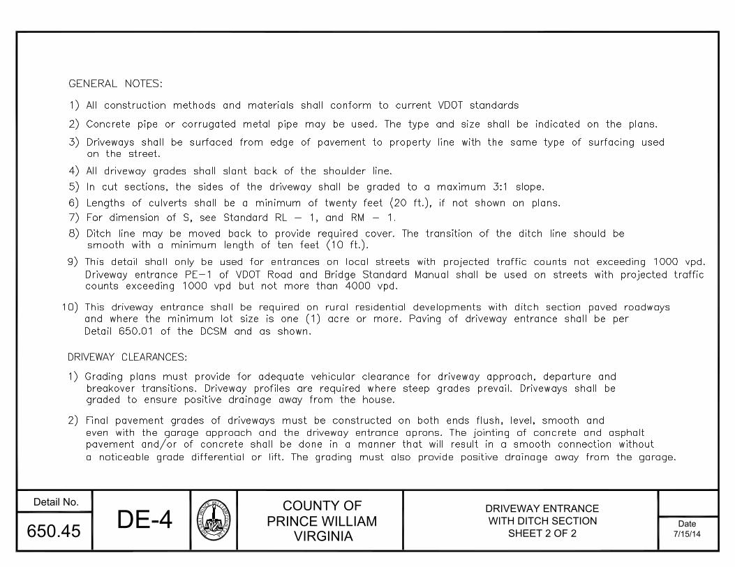
THESEALPRINC
EWILLIAMCOU
NTYVA
COUNTY OFPRINCE WILLIAM
VIRGINIADate
Detail No.
7/15/14650.45
breakover transitions. Driveway profiles are required where steep grades prevail. Driveways shall be1) Grading plans must provide for adequate vehicular clearance for driveway approach, departure and
8) Ditch line may be moved back to provide required cover. The transition of the ditch line should be
6) Lengths of culverts shall be a minimum of twenty feet (20 ft.), if not shown on plans.5) In cut sections, the sides of the driveway shall be graded to a maximum 3:1 slope.
3) Driveways shall be surfaced from edge of pavement to property line with the same type of surfacing used
2) Concrete pipe or corrugated metal pipe may be used. The type and size shall be indicated on the plans.
1) All construction methods and materials shall conform to current VDOT standards
graded to ensure positive drainage away from the house.
DRIVEWAY CLEARANCES:
7) For dimension of S, see Standard RL - 1, and RM - 1.
4) All driveway grades shall slant back of the shoulder line.
GENERAL NOTES:
smooth with a minimum length of ten feet (10 ft.).
on the street.
and where the minimum lot size is one (1) acre or more. Paving of driveway entrance shall be per10) This driveway entrance shall be required on rural residential developments with ditch section paved roadways
Detail 650.01 of the DCSM and as shown.
pavement and/or of concrete shall be done in a manner that will result in a smooth connection withouta noticeable grade differential or lift. The grading must also provide positive drainage away from the garage.
even with the garage approach and the driveway entrance aprons. The jointing of concrete and asphalt2) Final pavement grades of driveways must be constructed on both ends flush, level, smooth and
9) This detail shall only be used for entrances on local streets with projected traffic counts not exceeding 1000 vpd.Driveway entrance PE-1 of VDOT Road and Bridge Standard Manual shall be used on streets with projected trafficcounts exceeding 1000 vpd but not more than 4000 vpd.
DE-4 DRIVEWAY ENTRANCEWITH DITCH SECTION
SHEET 2 OF 2
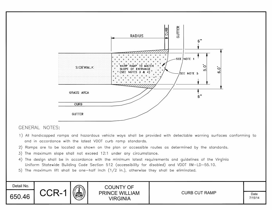
THESEALPRINC
EWILLIAMCOU
NTYVA
COUNTY OFPRINCE WILLIAM
VIRGINIADate
Detail No.
7/15/14650.46
GRASS AREA
RADIUS
CURB
CU
RB
GUTTER
GUTTER
5.0
'
6.0
'
6"
6"
GENERAL NOTES:
2) Ramps are to be located as shown on the plan or accessible routes as determined by the standards.3) The maximum slope shall not exceed 12:1 under any circumstance.4) The design shall be in accordance with the minimum latest requirements and guidelines of the Virginia
Uniform Statewide Building Code Section 512 (accessibility for disabled) and VDOT IIM-LD-55.10.5) The maximum lift shall be one-half inch (1/2 in.), otherwise they shall be eliminated.
SEE NOTE 5WARP RAMP TO MATCH
SLOPE OF ENTRANCE
(SEE NOTES 3 & 4)
SIDEWALK
and in accordance with the latest VDOT curb ramp standards.
1) All handicapped ramps and hazardous vehicle ways shall be provided with detectable warning surfaces conforming to
CCR-1 CURB CUT RAMP
SEE NOTE 1
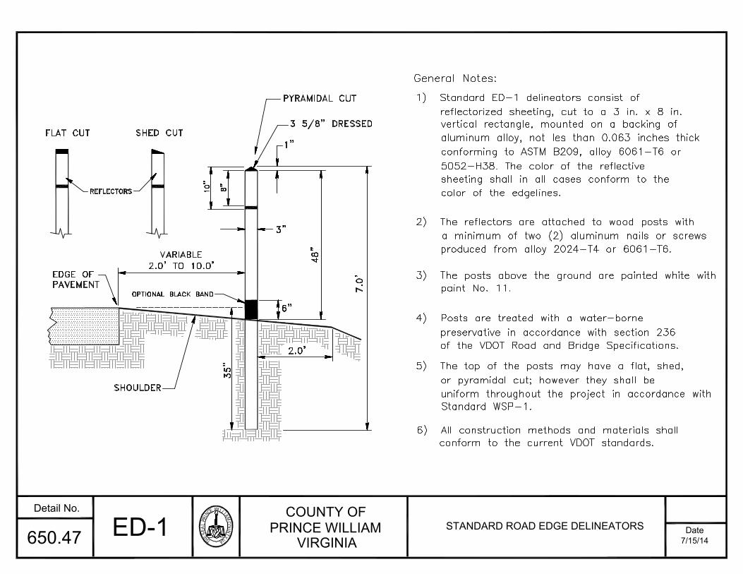
THESEALPRINC
EWILLIAMCOU
NTYVA
COUNTY OFPRINCE WILLIAM
VIRGINIADate
Detail No.
7/15/14650.47
6) All construction methods and materials shall
5) The top of the posts may have a flat, shed,
4) Posts are treated with a water-borne
3) The posts above the ground are painted white with
2) The reflectors are attached to wood posts with
1) Standard ED-1 delineators consist of
General Notes:
48"VARIABLE
PAVEMENTEDGE OF
35"
SHOULDER
OPTIONAL BLACK BAND
2.0' TO 10.0'
2.0'
6"
7.0
'
FLAT CUT
REFLECTORS 8"10"SHED CUT 1"
3"
PYRAMIDAL CUT
3 5/8" DRESSED
of the VDOT Road and Bridge Specifications.
conform to the current VDOT standards.
or pyramidal cut; however they shall beuniform throughout the project in accordance with
preservative in accordance with section 236
paint No. 11.
produced from alloy 2024-T4 or 6061-T6.
sheeting shall in all cases conform to the5052-H38. The color of the reflective
conforming to ASTM B209, alloy 6061-T6 oraluminum alloy, not les than 0.063 inches thickvertical rectangle, mounted on a backing ofreflectorized sheeting, cut to a 3 in. x 8 in.
color of the edgelines.
ED-1 STANDARD ROAD EDGE DELINEATORS
a minimum of two (2) aluminum nails or screws
Standard WSP-1.
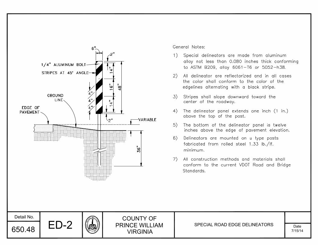
THESEALPRINC
EWILLIAMCOU
NTYVA
COUNTY OFPRINCE WILLIAM
VIRGINIADate
Detail No.
7/15/14650.48
48"
16"
14"
14"
2"
2"
VARIABLE
36"
EDGE OFPAVEMENT
GROUND
LINE
General Notes:
1) Special delineators are made from aluminumalloy not less than 0.080 inches thick conformingto ASTM B209, alloy 6061-T6 or 5052-h38.
2) All delineator are reflectorized and in all casesthe color shall conform to the color of the
edgelines alternating with a black stripe.
3) Stripes shall slope downward toward thecenter of the roadway.
4) The delineator panel extends one inch (1 in.)above the top of the post.
5) The bottom of the delineator panel is twelveinches above the edge of pavement elevation.
6) Delineators are mounted on u type postsfabricated from rolled steel 1.33 lb./lf.minimum.
7) All construction methods and materials shallconform to the current VDOT Road and BridgeStandards.
6"
1/4" ALUMINUM BOLT
4"
4"
4"
STRIPES AT 45° ANGLE
ED-2 SPECIAL ROAD EDGE DELINEATORS

THESEALPRINC
EWILLIAMCOU
NTYVA
COUNTY OFPRINCE WILLIAM
VIRGINIADate
Detail No.
7/15/14650.49
7) Where provision must be made for access of equipment and authorized vehicles, lockable gates may be provided in
6) Where necessary for safety of pedestrian traffic, a full extension of the barricade may be required to the limits of4 in. lag screws with washers. Bolts or screws are to be placed two inches (2 in.) from edge of planks.
5) Each plank shall be secured to each post with (2)-3/8 in x 6-1/2 in. carriage bolts or with (2) 7/16 in. x
4) Good quality oil base exterior grade paint must be used. Six inch (6 in.) high intensity reflective orange and white(6 in.) of the ground level.
1) Barricades shall be used at the end of pavement on all dead end streets.
4"X4" POSTS, 8.0' LONG
2) Posts and planks shall be in accordance with Section 236.02 (c) of VDOT's Road and Bridge Specifications.
GENERAL NOTES:
stripe tape on one side for the full length of the barricade.
one section of the barricade.
the right of way.
GROUND LINE
MIDDLE UNIT
6"
10.0' OC
44"
-6 If facing traffic in two directions-3 if facing traffic in one direction
Number of reflectorized rail faces:Width of rail - 8" min. to - 12" max.Color of stripes-Reflective orange and whiteCharacteristics:
20"
456"
20"9.0' OC
END UNIT 6"
5.0
'(M
IN)
3) Planks shall be painted completeley white. Posts shall be painted white on all sides to within six inches
TB-1 STANDARD TYPE IIITRAFFIC BARRICADE

THESEALPRINC
EWILLIAMCOU
NTYVA
COUNTY OFPRINCE WILLIAM
VIRGINIADate
Detail No.
7/15/14650.50
2) Minimum intersection turning radius shall
1) The pavement structure of the mainline
GENERAL NOTES:
POINT OF TANGENCY
(TYPICAL)25'(MIN.)
areas requiring stabilization shall be pavedshoulder. The remainder of the shoulderfoot (1 ft.) at the same slope into theroadway pavement shall be extended one
be fifty feet (50').
with one and one-half inch (1-1/2 in.)SM-9.5A.
SI-1 SHOULDER STABILIZATION ATINTERSECTIONS
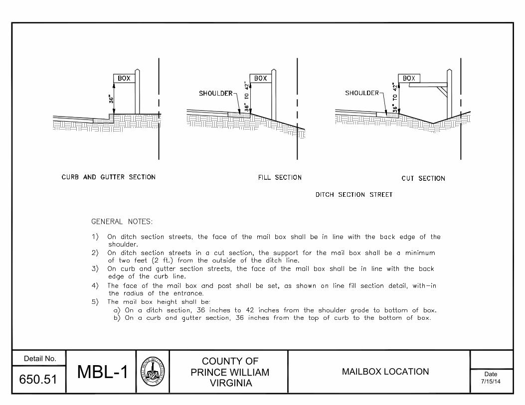
THESEALPRINC
EWILLIAMCOU
NTYVA
COUNTY OFPRINCE WILLIAM
VIRGINIADate
Detail No.
7/15/14650.51
DITCH SECTION STREET
b) On a curb and gutter section, 36 inches from the top of curb to the bottom of box.a) On a ditch section, 36 inches to 42 inches from the shoulder grade to bottom of box.
4) The face of the mail box and post shall be set, as shown on line fill section detail, with-in
3) On curb and gutter section streets, the face of the mail box shall be in line with the back
2) On ditch section streets in a cut section, the support for the mail box shall be a minimum
1) On ditch section streets, the face of the mail box shall be in line with the back edge of the
5) The mail box height shall be:
GENERAL NOTES:
of two feet (2 ft.) from the outside of the ditch line.
the radius of the entrance.
edge of the curb line.
CURB AND GUTTER SECTION
shoulder.
FILL SECTION
BOX
36"
BOX
36"
TO
42"
SHOULDER
CUT SECTION
BOX
SHOULDER
36"
TO
42"
MBL-1 MAILBOX LOCATION

THESEALPRINC
EWILLIAMCOU
NTYVA
COUNTY OFPRINCE WILLIAM
VIRGINIADate
Detail No.
7/15/14650.52
ROUTE # DECAL3/4" RADIUS, DIE CUT, ALL CORNERS
1234
1234
AV
DR
SR
SR
BACKGROUND TO BE GREEN HIGH INTENSITY
SNS-1 STREET NAME SIGN STANDARDSHEET 1 OF 2
2013
FHWA, SERIES "B" WHITE HIGH INTENSITYLETTERS (USE UPPER AND LOWER CASELETTERS)
YEAR SIGN INSTALLED OR REPLACED
1. POST MAY BE SET IN TAMPED EARTH OR
CONCRETE CLASS A3 IN ACCORDANCE WITH VDOT'SSTP-1 DETAIL.2. BREAK-AWAY POSTS ARE OPTIONAL.
CAST ALUMINUM ALLOY (ASTM B26-356-T6)BRACKET AND POST CAP WITH 5/16"CADMIUM PLATED, ALLEN HEAD, KNURLED SETSCREWS CAST OR MACHINED FOR 0.080THICK BLANKS SET SCREWS TO BE ONOPPOSITE SIDES OF SLOTS.
Kansas
2 3/8" OUTSIDE DIAMETERGALVANIZED STEEL POST
Lee

THESEALPRINC
EWILLIAMCOU
NTYVA
COUNTY OFPRINCE WILLIAM
VIRGINIADate
Detail No.
7/15/14650.52
* Dimensions may be modified as approved by the Director of Transportation.
Vertical 6 in. min. 9 in. min.
Horizontal 48 in. max. 48 in. max.
Horizontal 24 in. min. 30 in. min.
1. Street name signs shall conform to the standards in the table below for sizes as follows:
Message
Capitals/Numerals 1 in. C 2 in. C
Suffix Capitals 3 in. C 4 in. C
Street Name 4 in. C 6 in. C
Vertical 1.25 in. 2.50 in.
Horizontal (Field) 4 in. 6 in.
Route Decal
* Street Name Sign - Use Upper and Lower Case Letters
Route Decal
Color
Shape Horizontal Rectangle
GENERAL NOTES:
Field: Green (Reflectorized)Message: White (Reflectorized)
Size B: Arterials, parkways and collector streets
Size A: Subdivision streets
Street Name Sign
SNS-1 STREET NAME SIGN STANDARDSHEET 2 OF 2
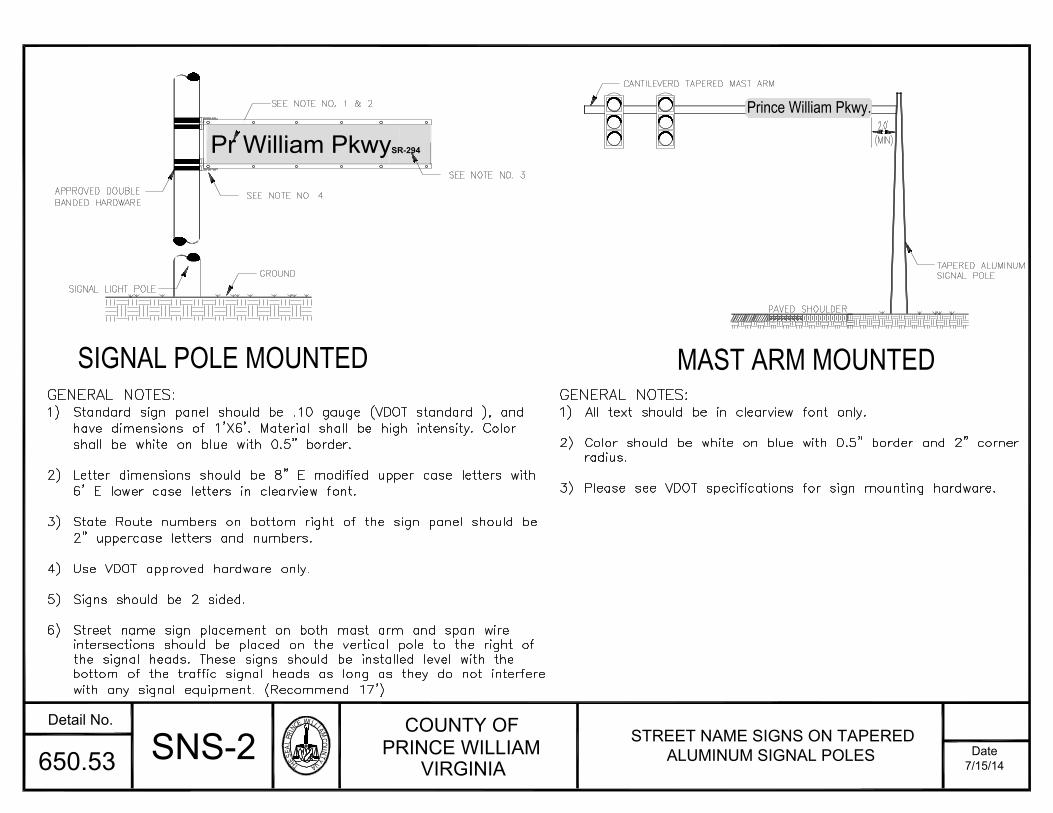
THESEALPRINC
EWILLIAMCOU
NTYVA
COUNTY OFPRINCE WILLIAM
VIRGINIADate
Detail No.
7/15/14650.53
SIGNAL POLE MOUNTED MAST ARM MOUNTED
SIGNAL LIGHT POLE
GROUND
APPROVED DOUBLESEE NOTE NO. 1 & 2
SEE NOTE NO. 4
Prince William Pkwy.CANTILEVERD TAPERED MAST ARM
TAPERED ALUMINUM
SIGNAL POLE
GENERAL NOTES:
1) Standard sign panel should be .10 gauge (VDOT standard ), andhave dimensions of 1'X6'. Material shall be high intensity . Color
shall be white on blue with 0.5" border.
2) Letter dimensions should be 8" E modified upper case letters with6' E lower case letters in clearview font.
3) State Route numbers on bottom right of the sign panel should be2" uppercase letters and numbers.
4) Use VDOT approved hardware only .
5) Signs should be 2 sided.
6) Street name sign placement on both mast arm and span wireintersections should be placed on the vertical pole to the right ofthe signal heads. These signs should be installed level with thebottom of the traffic signal heads as long as they do not interferewith any signal equipment. (Recommend 17' )
PAVED SHOULDER
GENERAL NOTES:
1) All text should be in clearview font only.
2) Color should be white on blue with 0.5" border and 2" cornerradius.
3) Please see VDOT specifications for sign mounting hardware.
(MIN)2.0'
BANDED HARDWARE
SNS-2 STREET NAME SIGNS ON TAPEREDALUMINUM SIGNAL POLES
SEE NOTE NO. 3
Pr William PkwySR-294
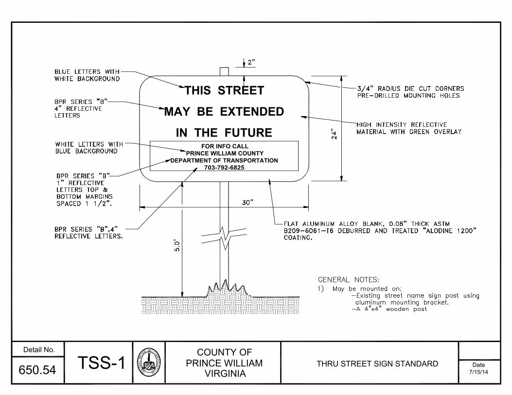
THESEALPRINC
EWILLIAMCOU
NTYVA
COUNTY OFPRINCE WILLIAM
VIRGINIADate
Detail No.
7/15/14650.54
B209-6061-T6 DEBURRED AND TREATED "ALODINE 1200"FLAT ALUMINUM ALLOY BLANK, 0.08" THICK ASTM
1) May be mounted on:GENERAL NOTES:
LETTERS TOP &REFLECTIVE LETTERS.BPR SERIES "B",4"
SPACED 1 1/2".BOTTOM MARGINS
5.0
' 30" COATING.1" REFLECTIVEBPR SERIES "B"
BLUE BACKGROUNDWHITE LETTERS WITH
LETTERS4" REFLECTIVEBPR SERIES "B"
WHITE BACKGROUNDBLUE LETTERS WITH
2"
-A 4"x4" wooden postaluminum mounting bracket.
-Existing street name sign post using
PRE-DRILLED MOUNTING HOLES3/4" RADIUS DIE CUT CORNERS
24"
TSS-1 THRU STREET SIGN STANDARD
HIGH INTENSITY REFLECTIVE
MATERIAL WITH GREEN OVERLAY
THIS STREET
MAY BE EXTENDED
IN THE FUTUREFOR INFO CALL
PRINCE WILLIAM COUNTYDEPARTMENT OF TRANSPORTATION
703-792-6825

THESEALPRINC
EWILLIAMCOU
NTYVA
COUNTY OFPRINCE WILLIAM
VIRGINIADate
Detail No.
7/15/14650.55
GENERAL NOTES:
NO OUTLET
DEAD END
W14-2P36"x12"36"x12"
W14-IPEND
30"x30"
W14-1
DEADOUTLET
W14-2
NO
30"x30"
DES-1 DEAD END/NO OUTLETSTREET SIGN STANDARD
1) Refer to the current VDOT Road and Bridge Standard STP-1, Square Tube Sign Post for post specifications andinstallation.
2) Post may be set in tamped earth or concrete class A3 in accordance with VDOT's STP-1 detail.3) The lowest portion of the signs shall be a minimum of seven (7) feet above the curb and gutter and five (5)feet above the crown on ditch section streets.
4) If plaques (W14-1P, 2P) are used in combination with the stop signs or the route markers, their placement shallbe per Note 3 above.5) Placement, sizes, and material specifications shall be in accordance with the requirements of the Manual onUniform Traffic Control Devices (MUTCD) unless otherwise directed by VDOT.
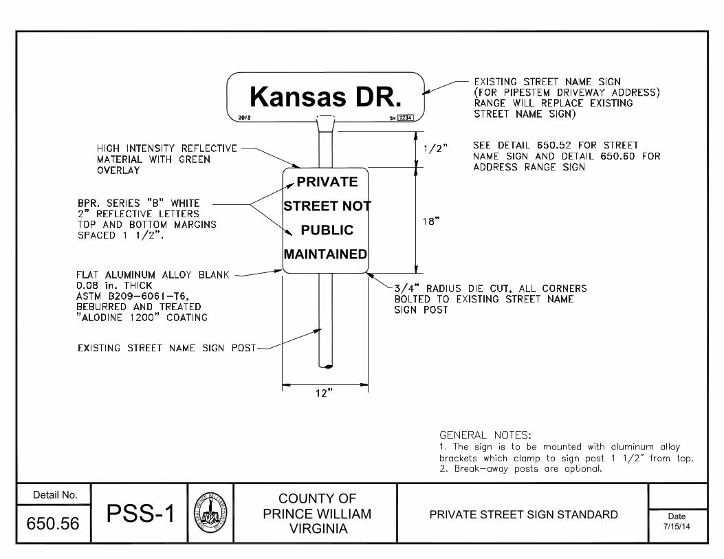
THESEALPRINC
EWILLIAMCOU
NTYVA
COUNTY OFPRINCE WILLIAM
VIRGINIADate
Detail No.
7/15/14650.56
SIGN POSTBOLTED TO EXISTING STREET NAME3/4" RADIUS DIE CUT, ALL CORNERS
18"
1/2"
EXISTING STREET NAME SIGN POST
"ALODINE 1200" COATINGBEBURRED AND TREATEDASTM B209-6061-T6,
FLAT ALUMINUM ALLOY BLANK0.08 in. THICK
12"
TOP AND BOTTOM MARGINS2" REFLECTIVE LETTERSBPR. SERIES "B" WHITE
SPACED 1 1/2".
RANGE WILL REPLACE EXISTING(FOR PIPESTEM DRIVEWAY ADDRESS)
STREET NAME SIGN)
EXISTING STREET NAME SIGN
PSS-1 PRIVATE STREET SIGN STANDARD
1234SR2013
GENERAL NOTES:
1. The sign is to be mounted with aluminum alloybrackets which clamp to sign post 1 1/2" from top.2. Break-away posts are optional.
HIGH INTENSITY REFLECTIVEMATERIAL WITH GREENOVERLAY
SEE DETAIL 650.52 FOR STREET
NAME SIGN AND DETAIL 650.60 FORADDRESS RANGE SIGN
Kansas DR.
PRIVATE
STREET NOT
PUBLIC
MAINTAINED
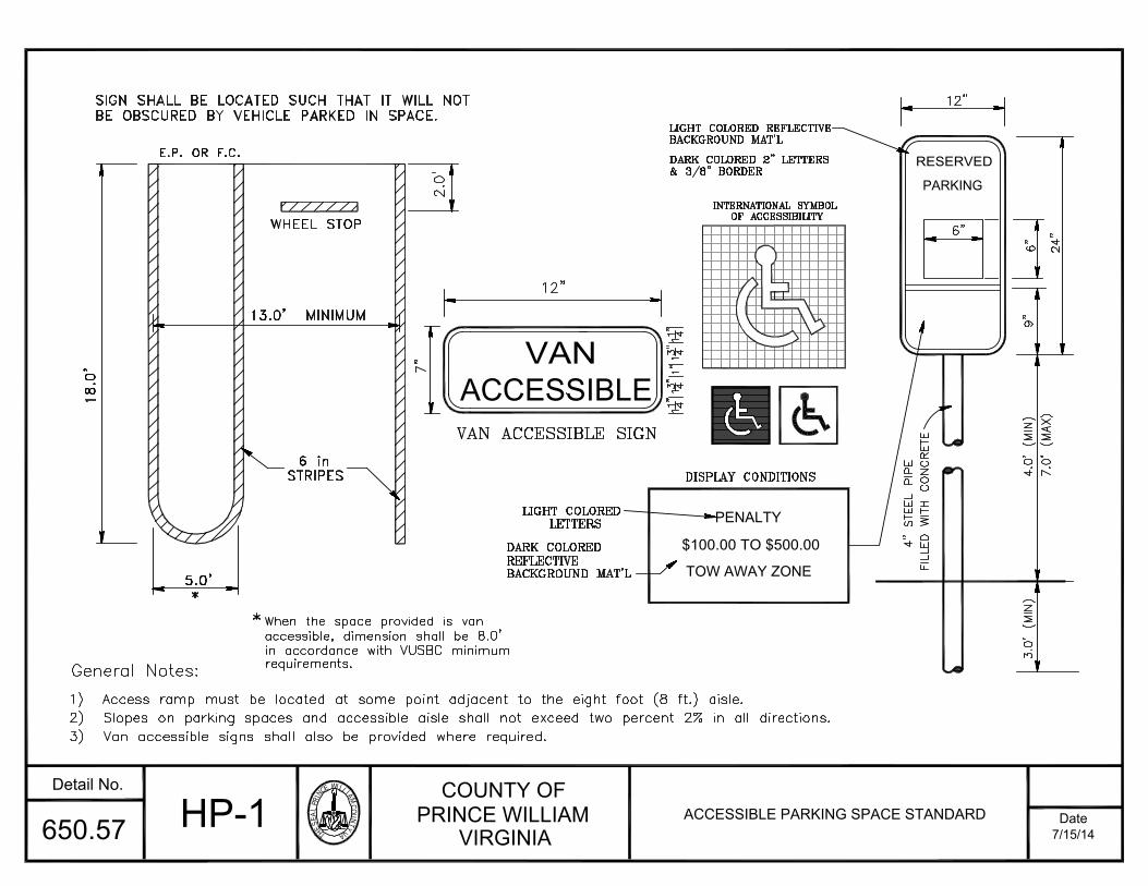
THESEALPRINC
EWILLIAMCOU
NTYVA
COUNTY OFPRINCE WILLIAM
VIRGINIADate
Detail No.
7/15/14650.57
2) Slopes on parking spaces and accessible aisle shall not exceed two percent 2% in all directions.
& 3/8" BORDERDARK COLORED 2" LETTERS
BACKGROUND MAT'LLIGHT COLORED REFLECTIVE
OF ACCESSIBILITYINTERNATIONAL SYMBOL
DISPLAY CONDITIONS
18.0
'
3) Van accessible signs shall also be provided where required.
1) Access ramp must be located at some point adjacent to the eight foot (8 ft.) aisle.
General Notes:
5.0'*
STRIPES
BACKGROUND MAT'LREFLECTIVEDARK COLORED
LETTERSLIGHT COLORED
BE OBSCURED BY VEHICLE PARKED IN SPACE.SIGN SHALL BE LOCATED SUCH THAT IT WILL NOT
13.0' MINIMUM
WHEEL STOP
E.P. OR F.C.
2.0
'
in accordance with VUSBC minimum
When the space provided is van
FIL
LE
D W
ITH
CO
NC
RE
TE
4"
ST
EE
L P
IPE
requirements.
*
7.0'
(MA
X)
4.0' (MIN)
12"
9"24"
6 in
6"
6"
VAN ACCESSIBLE SIGN
7"4
1"
12"
1"1
3"41
1
1"4
1
3"4
accessible, dimension shall be 8.0'
HP-1 ACCESSIBLE PARKING SPACE STANDARD
3.0' (MIN)
VANACCESSIBLE
PENALTY
$100.00 TO $500.00
TOW AWAY ZONE
RESERVED
PARKING
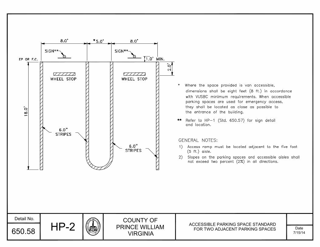
THESEALPRINC
EWILLIAMCOU
NTYVA
COUNTY OFPRINCE WILLIAM
VIRGINIADate
Detail No.
7/15/14650.58
8.0' 5.0' 8.0'*
WHEEL STOP1.0' MIN.
2.0
'
18.0
'
SIGN**SIGN**
6.0"STRIPES
STRIPES6.0"
* Where the space provided is van accessible,dimensions shall be eight feet (8 ft.) in accordancewith VUSBC minimum requirements. When accessibleparking spaces are used for emergency access,they shall be located as close as possible tothe entrance of the building.
Refer to HP-1 (Std. 650.57) for sign detailand location.
**
GENERAL NOTES:
1) Access ramp must be located adjacent to the five foot
not exceed two percent (2%) in all directions.
EP OR F.C.
(5 ft.) aisle.2) Slopes on the parking spaces and accessible aisles shall
HP-2 ACCESSIBLE PARKING SPACE STANDARDFOR TWO ADJACENT PARKING SPACES
WHEEL STOP
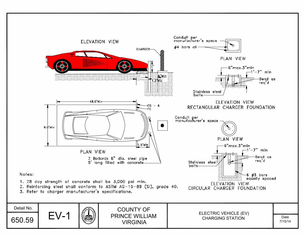
THESEALPRINC
EWILLIAMCOU
NTYVA
COUNTY OFPRINCE WILLIAM
VIRGINIADate
Detail No.
7/15/14650.59
Notes:
RECTANGULAR CHARGER FOUNDATION
PLAN VIEW
ELEVATION VIEWCIRCULAR CHARGER FOUNDATION
3. Refer to charger manufacturer's specifications.2. Reinforcing steel shall conform to ASTM AG-15-89 (SI), grade 40.1. 28 day strength of concrete shall be 3,000 psi min.
5' long filled with concrete2 Bollards 6" dia. steel pipe
9.0'Min
PLAN VIEWboltsStainless steel
1.5'Min
FC
Conduit permanufacturer's specs
equally spaced6 #3 bars
req'dBend as
6"max.3"min1'-7" min
Stainless steel
ELEVATION VIEW18.0'Min
ELEVATION VIEWCG - 6
1.5'Min
6"Min
bolts
CHARGER2'#4 bars all
manufacturer's specsConduit per
PLAN VIEW
req'dBend as1'-7" min6"max.3"min
EV-1 ELECTRIC VEHICLE (EV)CHARGING STATION

THESEALPRINC
EWILLIAMCOU
NTYVA
COUNTY OFPRINCE WILLIAM
VIRGINIADate
Detail No.
7/15/14650.60
5) The sign shall be located outside the existing or
3.0'
proposed roadway right of way.
pipestem driveway and outside of the sight1) The sign shall be placed on right side of the
pipestem driveway, house numbers and the words2) The sign shall include the street name of the
3) The lettering on the sign should be 2" inheight. The background shall be made of green
4) Alternate design will require pre-approval fromthe Director of Transportation.
ALL CORNERS3/4" RADIUS
5.0'
24"
18"
distance easement.
"Private Street" or "Private Drive."
reflective materials.
General Notes:
ARS-1 ADDRESS RANGE SIGN FOR PIPESTEMS
2 3/8" OUTSIDE DIAMETERGALVANIZED STEEL POST
6) Break-away posts are optional.
JAVIER DRIVE12600-1260212604-1260612606-12608
PRIVATEDRIVE
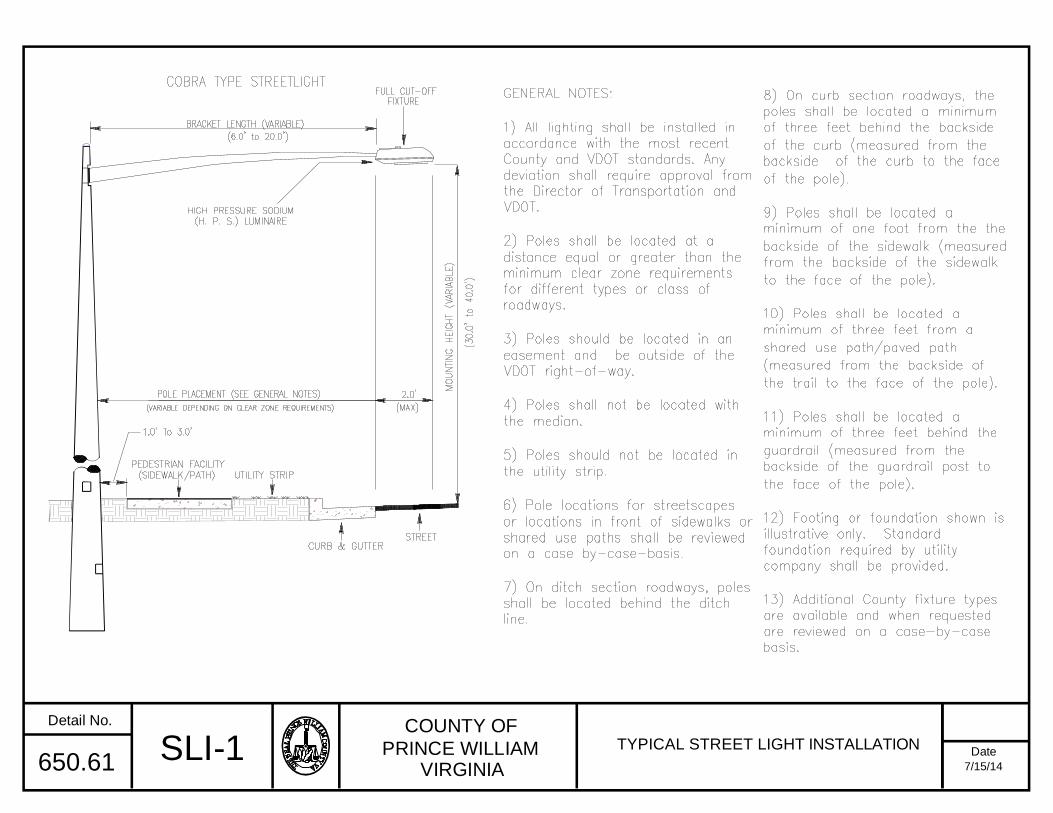
COUNTY OF
PRINCE WILLIAMVIRGINIA
Date
Detail No.
7/15/14650.61 SLI-1 TYPICAL STREET LIGHT INSTALLATION

THESEALPRINC
EWILLIAMCOU
NTYVA
COUNTY OFPRINCE WILLIAM
VIRGINIADate
Detail No.
7/15/14650.62
1) Applicable for use on commercial, shopping center,
2) Speed humps locations shall require approval of the
water valves, roof drains, and handicapped crossings.4) Locations of speed humps should avoid manholes,
of 300 to 500 feet spacing.3) Speed humps should be used in series
Transportation prior to installation.Department of Fire and Rescue and Director of
GENERAL NOTES:
1'
1'
1'
1'
2'
2'
2'
2'
2'1'
CENTER OF
1'
2' DIRECTION OFTRAFFIC
EDGE OF
GUTTER
PLAN VIEW
CURB FACEEDGE DETAIL
DIRECTION OFTRAFFIC
TRAVELWAY
HUMP
30"x30"SPECIAL
SPEED
W13 - 1
24"x24"
15M.P.H.
office and other land use sites approved by theDirector of Transportation.
2'
2'
2'
2'
1'
1'
1'
SIDEWALKSIDEWALK1 FOOT WIDE STRIPES TYP.
NOTE : NUMBER OF 1 FOOT WIDE STRIPES DEPENDSON THE WIDTH OF HUMP. START 1ST STRIPEIN CENTER OF TRAVELWAY.
5) Signs and pavement markings shall be in accordance
CROSS SECTION
12'-0"
TYPICAL TRAFFIC SIGN
1'-0"
Typ.1.7" 2.3" 2.7" 2.9" 3.0"1.0"TRAFFIC SIGNTRAFFIC SIGN
12"
2 FOOT WIDE TYP.
PTS-1 PRIVATE TRAVELWAYSPEED HUMPS
3"

THESEALPRINC
EWILLIAMCOU
NTYVA
COUNTY OFPRINCE WILLIAM
VIRGINIADate
Detail No.
7/15/14650.63 APW-1 ASPHALT PAVEMENT WIDENING FORWIDENING SUBJECT TO TRAFFIC
NOTES:
1) Asphalt pavement widening shall have a pavement design in accordance with current VDOT procedures and be approved bythe Engineer.2) The pavement design for asphalt pavement widening shall meet or exceed the depths and types of the layers of existingpavement. Subsurface drainage of the existing and proposed pavement shall be addressed in the pavement design.3) A minimum of three cores shall be taken along the center of the adjacent travel lane to determine the type and thicknessof existing pavement layers. These cores shall be spaced no more than 500 feet apart.4) The adjacent travel lane shall be milled a minimum depth of 1-1/2 inches and replaced with an asphalt surface course tomatch the proposed pavement widening surface course, unless waived by the Engineer.5) The Engineer may required the milling depth of the existing pavement to be adjusted to achieve an acceptable pavementcross slope and effective surface drainage.6) Existing pavement markings and markers within the project limits shall be restored subject to the approval of the Engineer.7) Final transverse pavement tie-in shall conform to the requirements of Section 315.05 (c) of the specifications except thatall joints at tie-in locations shall be tested using a 10-foot straightedge in accordance with the requirements of Section315.07 (a) of the latest VDOT Road and Bridge Specifications Manual.
ADJACENT TRAVEL LANE ASPHALT PAVEMENT WIDENING
12"*
EDGE OF EXISTING PAVEMENT
(AS DETERMINED IN FIELD)
TACK COAT THE PROPOSEDCONSTRUCTION JOINT
EXISTING SURFACE PROPOSED SUBBASE
PROPOSED ASPHALT LAYERSEXISTING ASPHALTLAYERS
COMPACTED SUBGRADE
CONSTRUCTION JOINT DETAILRemove existing asphalt layers to existing subbase and replace with proposed asphaltwidening layers.
Proposed minimum 1-1/2 inch thick asphalt surface course (See Note 5).
Minimum 12 inches or greater as necessary to abut the full thickness of existingasphalt layers as determined by cores (See Note 3).
*
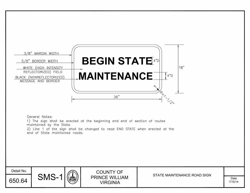
THESEALPRINC
EWILLIAMCOU
NTYVA
COUNTY OFPRINCE WILLIAM
VIRGINIADate
Detail No.
7/15/14650.64 SMS-1 STATE MAINTENANCE ROAD SIGN
General Notes:
1) The sign shall be erected at the beginning and end of section of routesmaintained by the State.2) Line 1 of the sign shall be changed to read END STATE when erected at theend of State maintained roads.
BEGIN STATEMAINTENANCE
3/8" MARGIN WIDTH
5/8" BORDER WIDTH
WHITE (HIGH INTENSITYREFLECTORIZED) FIELD
BLACK (NONREFLECTORIZED)MESSAGE AND BORDER
4"D4"D
36"
18"
R=1-1/2"