Embed Size (px)
Citation preview
600-1 REV 05/15/15
SECTION 600: STREET LIGHTING & TRAFFIC SIGNALS
Page No. Description 600-2 601 GENERAL 600-2 601.1 SPECIFICATIONS 600-2 601.2 RESOLUTION OF CONFLICTS 600-2 601.3 START OF CONSTRUCTION 600-2 601.4 AS-BUILTS 600-3 602 MATERIALS 600-3 602.1 GENERAL 600-3 602.2 STREET LIGHTING POLES 600-5 602.3 BREAK-AWAY DEVICE 600-5 602.4 STREET LIGHTING POLE FOUNDATIONS 600-7 602.5 LUMINAIRES 600-9 602.6 PHOTO-CELL 600-10 602.7 UNDERGROUND CONDUITS AND ELECTRICAL CABLE 600-11 602.8 ELECTRICAL CABLE, 600 VOLT 600-11 602.9 LIGHTING CABLE FUSE KITS 600-12 602.10 STREET LIGHTING HANDHOLES 600-12 602.11 COMPOSITE CONCRETE JUNCTION BOX 600-13 602.12 GROUNDING 600-13 602.13 GROUND ROD 600-14 602.14 STREET LIGHTING CONTROLLER 600-20 603 CONSTRUCTION REQUIREMENTS 600-20 603.1 TRAFFIC SIGNAL SYSTEMS CONTRACTOR PRE-QUALIFICATIONS 600-20 603.2 TRENCH AND BACKFILL FOR ELECTRICAL WORK 600-20 603.3 YELLOW WARNING TAPE OVER STREET LIGHTING CABLE 600-20 603.4 TRAFFIC SIGNAL SYSTEM SERVICE INSTALLATION 600-22 604 INSPECTIONS AND TESTING 600-22 604.1 STREET LIGHTING SYSTEMS 600-22 604.2 TRAFFIC SIGNAL SYSTEMS 600-23 690 STANDARD DETAILS
Section 6: Street Lighting & Traffic Signals Naperville Standard Specification
600-2 REV 05/15/15
601 GENERAL The standards and requirements found in this article are for the materials and construction of street lighting and traffic signal systems within the City of Naperville, Illinois. 601.1 SPECIFICATIONS All work and equipment performed and installed under this section shall be governed by and shall comply with the following specifications, manuals, and codes listed in Section 102.2. The most current editions and all subsequent revisions and alterations for the specifications are required. 601.2 RESOLUTION OF CONFLICTS In the event of conflict between the City Standard Specifications and the documents listed in Section 102.2, the City Standard Specifications shall take precedence and/or the City Engineer’s decision will prevail. Any questions arising from these specifications should be directed in writing to the City Engineer for a determination. 601.3 START OF CONSTRUCTION The contractor shall not begin construction until all required permits have been obtained. Copies of all permits obtained by outside agencies must be provided to the city prior to the start of construction. 601.4 AS-BUILTS Upon completion of work, the contractor shall provide as-built information in conformance with the requirements of Section 110.
Section 6: Street Lighting & Traffic Signals Naperville Standard Specification
600-3 REV 05/15/15
602 MATERIALS 602.1 GENERAL The materials and equipment for installation of street lighting on public streets in Naperville are detailed in the following sections. Other street lighting equipment, such as the East Central Homeowners Organization (ECHO) decorative neighborhood street lights, the Central Business District (CBD) lights, and the Riverwalk lights are restricted for use on public streets in their designated areas (ECHO, the CBD and the Riverwalk), unless otherwise directed by the City Council. Specialized lighting equipment for CBD, ECHO, and other designated areas within the City shall be identical to existing equipment unless otherwise directed by the City Engineer. CBD lighting equipment shall meet the specifications in the CBD Downtown Streetscape Plan unless otherwise directed by the City Engineer. 602.2 STREET LIGHTING POLES
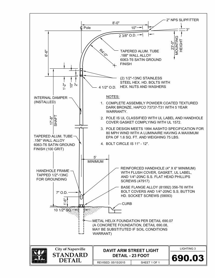
602.2.1 RESIDENTIAL AND NEIGHBORHOOD CONNECTOR STREETS
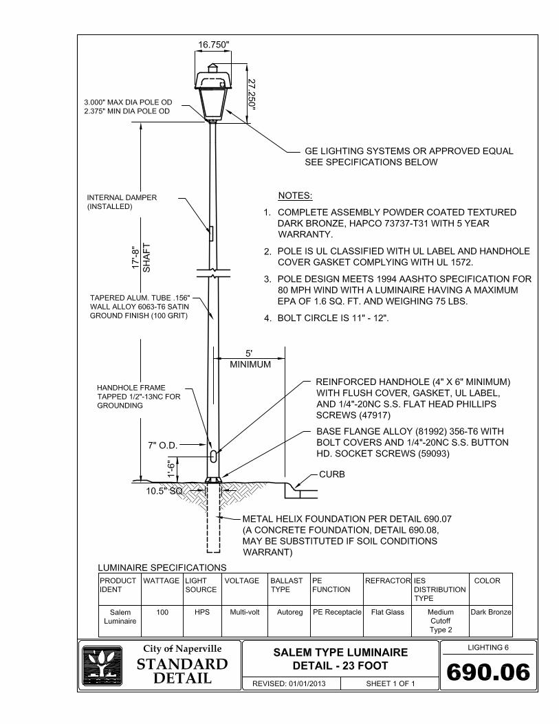
a) Street lighting poles for residential and neighborhood connector streets shall be of aluminum material, for a 23 foot mounting height of the luminaire, with an 8 foot luminaire arm, on a 5 foot metal foundation in accordance with the IDOT Standard Specifications. The contractor shall submit the technical information, to include catalog cut sheets, for each electrical material item for approval prior to ordering the equipment. The pole shall be “UL Listed” with a UL Classification label as complying with UL Standard 1572.
b) The outside diameter of the top of the pole shall not be less than 4.5 inches. c) The outside diameter of the pole at the base shall not be less than 7 inches. d) The wall thickness shall be a minimum of 0.156 inches. e) The bolt circle of the pole base shall be a minimum of 10 inches and a maximum of 11
inches in diameter. f) Anchor bolt covers shall be made of aluminum, conforming to ASTM B 208, S5A-F, or
B 26, SG70A. The anchor bolt covers shall be fastened to the base with 1/4 inch - 20 threaded stainless steel hex head bolts. The bolts shall be coated with an anti-seize compound during installation.
g) All poles shall be equipped with a flush mounting aluminum handhole of minimum size
of 4 inches by 6 inches. Handhole covers shall be fastened to the pole with 1/4 inch - 20 x 1/2 inch stainless steel philips head screws. The screws shall be coated with an anti-seize compound during installation.
Section 6: Street Lighting & Traffic Signals Naperville Standard Specification
600-4 REV 05/15/15
h) The luminaire mast arm shall be a davit “fishing pole” of 4 1/2 inch diameter tapered to 2 3/8 inch diameter of bending radius 4 feet. The davit arm shall be fastened to the pole by 1/2 inch stainless steel bolts, nuts, and lockwashers.
i) The pole and davit arm shall be finished in a Dark Bronze Powder Coat finish over 100
grit polished finished surface. The Dark Bronze Powder Coat finish shall have a minimum 5-year guarantee by the manufacturer.
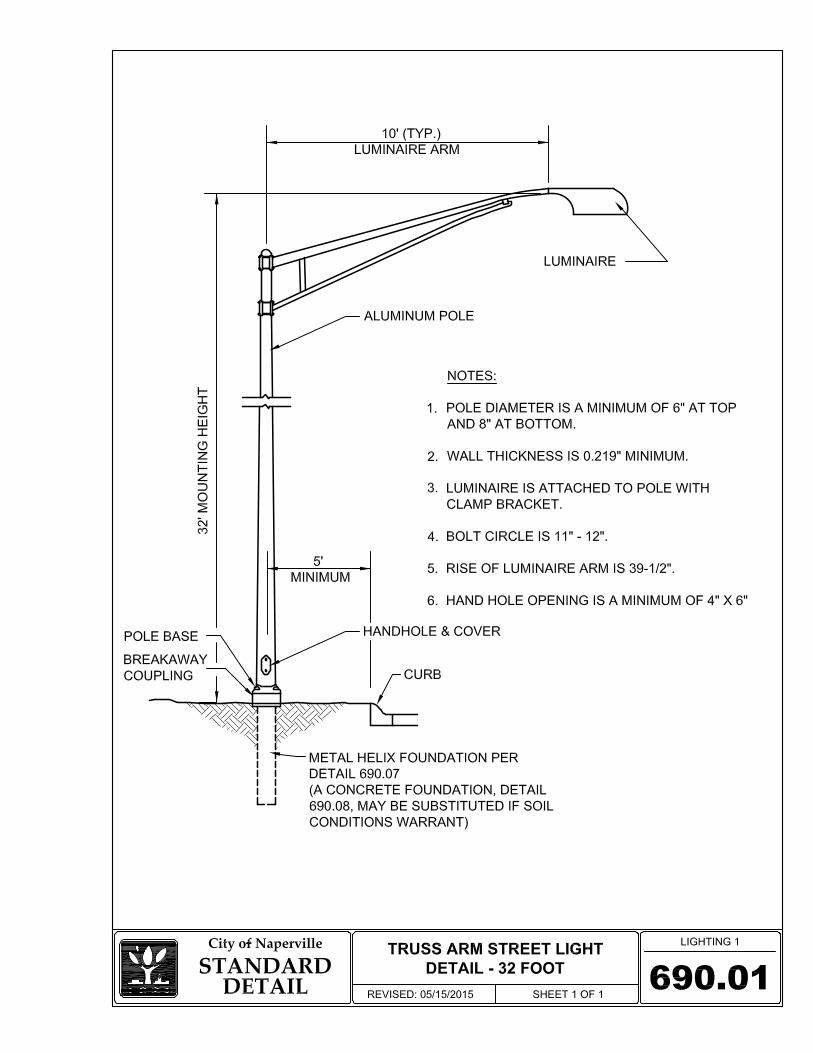
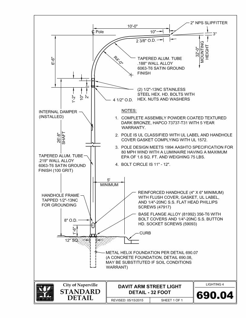
602.2.2 COLLECTOR AND ARTERIAL STREETS
a) Street lighting poles for collector and arterial streets shall be of aluminum material, for 32 foot and 40 foot mounting height of the luminaire, with 10 foot and 12 foot luminaire arms, on a 7 foot metal foundation in accordance with the IDOT Standard Specifications. The contractor shall submit the technical information, to include catalog cut sheets, for each electrical material item for approval prior to ordering the equipment. The pole shall be “UL Listed” with a UL Classification label as complying with UL Standard 1572.
b) The outside diameter of the top of the pole shall not be less than 6 inches. c) The outside diameter of the pole at the base shall not be less than 8 inches. d) The wall thickness shall be a minimum of 0.219 inches. e) The bolt circle of the pole base shall be a minimum of 11 inches and a maximum of 12
inches in diameter. f) Anchor bolt covers shall be made of aluminum, conforming to ASTM B 208, S5A-F, or
B 26, SG70A. The anchor bolt covers shall be fastened to the base with 1/4 inch – 20 threaded stainless steel hex head bolts. The bolts shall be coated with an anti-seize compound during installation.
g) All poles shall be equipped with a flush mounting aluminum handhole of minimum size
of 4 inches by 6 inches. Handhole covers shall be fastened to the pole with 1/4 inch - 20 x 1/2 inch stainless steel philips head screws. The screws shall be coated with an anti-seize compound during installation.
h) The luminaire mast arm for 10 foot shall be either of the truss type or may be a davit
“fishing pole” of 4 1/2 inch diameter tapered to 2 3/8 inch diameter of bending radius 5 feet. The luminaire mast arm for 12 foot arms shall be of the truss type. The rise of the truss arm shall be 39 inches. The mast arm shall be secured to the pole shaft by a clamp type bracket. The mast arm shall be mounted to the pole by a clamp style bracket by four 1/2 inch stainless steel bolts, nuts, and lockwashers. Top members of the mast arm shall have raceway openings extending through the bracket. Raceway openings shall be free of burrs and rough edges that may injure or damage pole wiring.

Section 6: Street Lighting & Traffic Signals Naperville Standard Specification
600-5 REV 05/15/15
i) The pole and davit arm for a 32 foot mounting height and a 10 davit arm shall be finished in a Dark Bronze Powder Coat finish over 100 grit polished finished surface. The Dark Bronze Powder Coat finish shall have a minimum 5-year guarantee by the manufacturer
602.3 BREAK-AWAY DEVICE Each collector or arterial lighting pole shall be connected to the foundation by a breakaway device of a frangible box design. Frangible coupling bolts are not acceptable. The breakaway device shall comply with the IDOT Standard Specifications. The device shall be approximately 9 inches tall and shall have an aluminum access door. Certification shall be submitted from the supplier of a breakaway device that the particular design meets the 1985 AASHTO breakaway specification. The contractor shall submit the technical information, to include catalog cut sheets. Breakaway devices installed on powder coated poles shall be powder coated to match the color of the pole. 602.4 STREET LIGHTING POLE FOUNDATIONS
602.4.1 METAL FOUNDATION – RESIDENTIAL AND NEIGHBORHOOD CONNECTOR
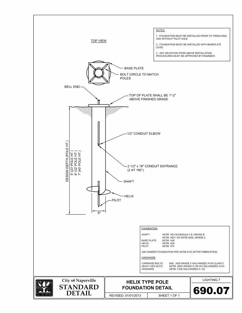
a) Metal foundations for street lighting poles for residential and neighborhood connector streets shall be 5 feet in length. The contractor shall submit the technical information, to include catalog cut sheets, for the metal foundation for approval prior to ordering the equipment.
b) The metal foundation, 5 foot, shall comply with the requirements of Section 1070.01 of
the IDOT Standard Specifications and be manufactured and certified by A.B. Chance Company or approved equal by the Engineer.
c) The base plate shall be 12 inch by 12 inch by 1 inch thick and shall be hot dipped
galvanized per ASTM-A123. The bolt circle shall be 10-1/2 inch in diameter. The base plate shall have holes drilled and tapped to accept 1 inch diameter threaded studs. The base plate shall be clearly and permanently marked to easily identify the location of the two cable way openings in the shaft. The shaft shall be from ASTM-A252, grade 2 steel.
d) The shaft shall be 8 inches in diameter, machine flame cut to a 5 foot length, with two 12
inch by 3 inch cable ways located 9 inches below the base plate separated by 180 degrees. The shaft shall be hot dipped galvanized per ASTM-A123 and be capable of withstanding 13,000-foot pounds of torque after being joined to the base plate.
e) The helix shall be produced by welding 3/8 inch thick steel in a 16 inch diameter helix
with a 3 inch pitch to allow for the passage of thicker gravel. f) The pilot point shall be sheared on a 45 degree angle from 1-1/4 inch round steel bar
made of ASTM-M183 steel and at least 6 inches in length. g) The studs shall be 1 inch diameter in accordance with AASHTO M 314. Nuts shall be
hexagon nuts according to AASHTO M 291M and washers shall be according to
Section 6: Street Lighting & Traffic Signals Naperville Standard Specification
600-6 REV 05/15/15
AASHTO M293. Studs, nuts, and washers shall be hot dip galvanized according to AASHTO 232.
602.4.2 METAL FOUNDATION – COLLECTOR AND ARTERIAL STREETS
a) Metal foundations for street lighting poles for arterial and collector streets shall be 7 feet
in length. The contractor shall submit the technical information, to include catalog cut sheets, for the metal foundation for approval prior to ordering the equipment. Metal foundations for use with a 32 foot mounting height pole may be 6 feet in length with the approval of the engineer.
b) The metal foundation, 7 foot, shall comply with the requirements of the IDOT Standard
Specifications and be manufactured and certified by A.B. Chance Company or approved equal by the engineer.
c) The base plate shall be 1-1/4 inches thick and shall be hot dipped galvanized per ASTM-
A123. The bolt circle shall be 11-1/2 inches in diameter. The base plate shall have holes drilled and tapped to accept 1 inch diameter threaded studs. The base plate shall be clearly and permanently marked to easily identify the location of the two cable way openings in the shaft.
d) The shaft shall be from ASTM-A252, grade 2 steel. The shaft shall be 10 inches in
diameter, machine flame cut to a 7 foot length, with two 27 inch by 3 inch cable ways located 9 inches below the base plate separated by 180 degrees. The shaft shall be hot dipped galvanized per ASTM-A123 and be capable of withstanding 13,000-foot pounds of torque after being joined to the base plate.
e) The helix shall be produced by welding 3/8 inch thick steel in a 16 inch diameter helix
with a 3 inch pitch to allow for the passage of thicker gravel. f) The pilot point shall be sheared on a 45 degree angle from 1-1/4 inch round steel bar
made of ASTM-M183 steel and at least 6 inches in length. g) The studs shall be 1 inch diameter in accordance with AASHTO M 314. Nuts shall be
hexagon nuts according to AASHTO M 291M and washers shall be according to AASHTO M293. Studs, nuts, and washers shall be hot dip galvanized according to AASHTO 232.
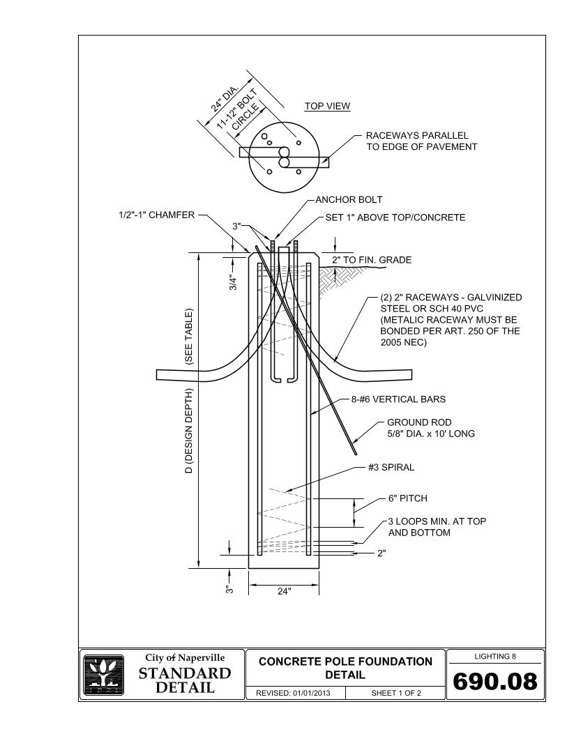
602.4.3 CONCRETE FOUNDATION Where soil conditions make it impossible to install metal foundations for street lighting poles, reinforced concrete foundations may be used.
a) The concrete foundation shall comply with the requirements of the IDOT Standard
Specifications.
Section 6: Street Lighting & Traffic Signals Naperville Standard Specification
600-7 REV 05/15/15
b) Studs, Fasteners, Rods: Studs or rods shall be 1 inch diameter and shall be according to AASHTO M 314. Nuts shall be hexagon nuts according to AASHTO M 291 M (M291) and washers shall be according to AASHTO M293. Studs or rods, nuts and washers shall be hot dip galvanized according to AASHTO M232.
c) Each foundation shall include a copper coated steel ground rod not less than 3/4 inch in
diameter and not less than 10 feet in length. d) Reinforced street lighting pole foundations shall be a minimum of 24 inches in diameter.
The outside top edge of the foundation shall have a 3/4 inch chamfer. The top of the finished foundation shall not protrude more than 4 inches above the finished grade. The anchor bolts, studs, or rods shall protrude a minimum of 3 inches above the concrete foundation.
e) The bolt circle shall be 11-1/2 inches in diameter unless otherwise specified for
residential street light poles. The anchor bolts shall be inside the cage of reinforcing steel.
f) Concrete shall be class SI concrete. g) Conduit raceways shall be 2 inches for insertion of 1-1/4 inch unit duct conduit.
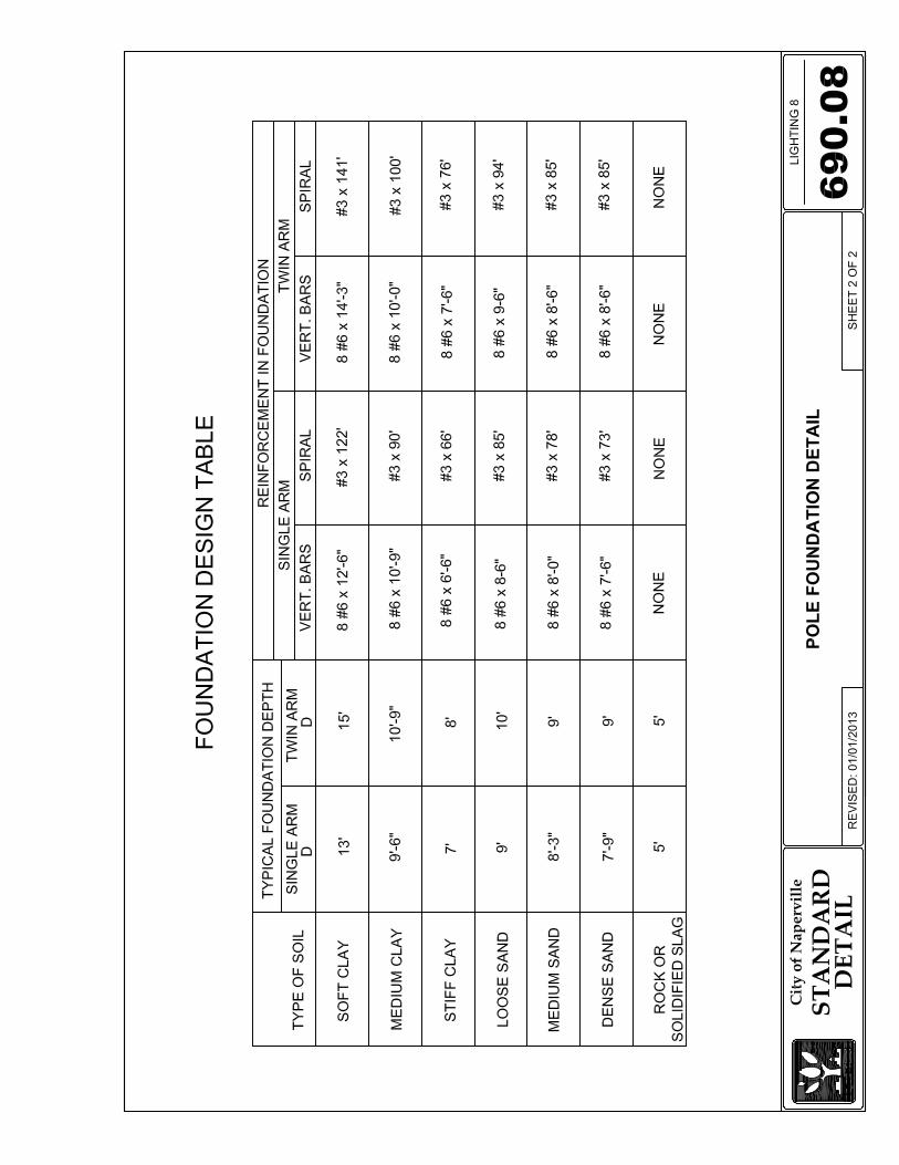
Raceways shall exit the foundation into the soil a minimum of 30 inches below the grade. h) The depth of the foundation shall be as directed by the City Engineer and constructed as
shown in Naperville Standard Detail 690.08, based upon an evaluation of the soil conditions encountered.
602.5 LUMINAIRES
602.5.1 RESIDENTIAL AND NEIGHBORHOOD CONNECTOR STREETS
a) The reflector, refractor or lens and the entire optical assembly shall not develop any discoloration over the normal life span of the luminaire.
b) The luminaire shall have a low loss, auto regulator type ballast for multi-volt
(120/208/240/277) operation set for 120 volt connection. c) The luminaire shall be of the modular component design with “power door”. d) Each luminaire shall be equipped with a 120/240 volt photocell receptacle and a photo-
cell which meets the requirements of Section 602.6. e) Street lighting luminaires for residential streets shall be a 100 watt HPS flat lens fixture
with medium cut-off photometrics for a Type II distribution. The 100 watt HPS
Section 6: Street Lighting & Traffic Signals Naperville Standard Specification
600-8 REV 05/15/15
luminaire shall be a General Electric M2AC10S0A2GMC21 or equal as approved by the Engineer.
f) Street lighting luminaires for neighborhood connector streets shall be a 150 watt HPS flat
lens fixture with medium cut-off photometrics for a Type II distribution. The 150 watt HPS luminaire shall be a General Electric M2AC15S0A2GMC21 or equal as approved by the engineer.
g) The lamp shall be of clear finish, be heat and shock resistant, and be capable of operating
in a horizontal burning position, and shall meet the applicable requirements of the IDOT Standard Specifications.
h) Street lighting luminaries installed on dark bronze powder coated poles shall be dark
bronze in color.
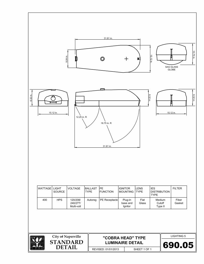
602.5.2 COLLECTOR AND ARTERIAL STREETS
a) Street lighting luminaires for collector streets shall be 250 watt HPS flat lens fixture with medium cut-off photometrics for a Type II distribution.
b) Street lighting luminaires for arterial streets shall be a 310 and 400 watt HPS flat lens
fixture with medium cut-off photometrics for a Type II distribution. c) The reflector, refractor or lens and the entire optical assembly shall not develop any
discoloration over the normal life span of the luminaire. d) The luminaire shall have a low loss, auto regulator type ballast for multi-volt
(120/208/240/277) operation set for 120 volt connection. e) The luminaire shall be of the modular component design with “power door”. f) Each luminaire shall be equipped with a 120/240 volt photo-cell receptacle and a shorting
cap or photo-cell which meets the requirements of Section 602.6. g) The luminaires shall be one of the following.
1) The 400 watt H.P.S. luminaire shall be General Electric MDCL40S0A22FMC21 or equal as approved by the Engineer.
2) The 310 watt H.P.S. luminaire shall be General Electric MDCL31S0A22FMC21 or
equal as approved by the Engineer. 3) The 250 watt H.P.S. luminaire shall be General Electric MDCL25S0A22FMC21 or
equal as approved by the Engineer.
Section 6: Street Lighting & Traffic Signals Naperville Standard Specification
600-9 REV 05/15/15
h) The lamp shall be of clear finish, be heat and shock resistant, and be capable of operating in a horizontal burning position, and shall meet the applicable requirements of the IDOT Standard Specifications.
i) Street lighting luminaries installed on dark bronze powder coated poles shall be dark
bronze in color. 602.6 PHOTO-CELL Photo cells shall be DTL D124-1.5-STJ or Sunrise Technologies S124-1.5-STM with time delay and pointed photo-electric controls (photo cells) cover unless otherwise approved by Engineer. Photo-electric control, dual volt, locking type (Twistlock) must meet or exceed the following requirements:
a) ANSI C136.10-1988. b) Line voltage Operating Range of 105 to 300 VAC at 60 Hz. c) Load Rating of 1000 watts tungsten and 1800 VA ballast. d) Failure mode (per ANSI) shall be to “on” mode. e) Photosensor shall be Cadmium Sulfide shall be sealed to prevent moisture and
contamination damage. This is to be accomplished by a conformal coating, epoxy encapsulation, or a glass to metal hermetic seal.
f) Turn “on” mode calibrated at 1.6 +/- 0.3 foot candles at 120 VAC with turn “off”
maximum ratio to turn “on” of 1.5:1. g) Time delay: Control shall have an instantaneous “on” response to allow for easy testing.
Operating temperature shall have a minimal effect on time delay duration. h) Surge protection shall be in the form of a Metal Oxide Varistor (MOV) wired line to
neutral. MOV shall be a minimum of 160 joules. Secondary surge protection across the electronic circuit is required.
i) Calibration: Each unit shall be calibrated in production using a photometer whose accuracy
is traceable to the NIST. A quality control inspection shall be performed after calibration and final assembly.
j) Contact “Chatter” on opening of contacts (TURN OFF of photoelectric control) shall not
exceed 6 milliseconds.
Section 6: Street Lighting & Traffic Signals Naperville Standard Specification
600-10 REV 05/15/15
k) Housing strength: The cover of the photo-electic control shall be of an impact and UV resistant material. Impact resistance of greater than 1.0 ft-lbs over the intended operating temperature range of the device is required.
l) Drop Test: The photoelectric control must be capable of withstanding a drop of 3 feet to a
concrete floor without causing damage to the housing and without changing the electrical operation.
m) Housing Size: The diameter of the photo-electric control skirt shall be a minimum of 3
inches. n) Plug blades shall be 3-prong, of brass construction and of the locking-type. o) Markings: The following information shall be marked upon the exterior of the photo-
electric control upon the base: month and year of manufacture, individual serial numbers, complete model description, operating voltage range, load rating, and provisions for marking installation and removal dates.
p) Warranty: The warranty for the photo-electric control shall be a minimum of 4 years.
602.7 UNDERGROUND CONDUITS AND ELECTRICAL CABLE Wiring to distribute electrical energy to street lighting will be installed underground. All wiring and cabling shall be copper conductor.
602.7.1 UNIT DUCT, 1-1/4 INCH, WITH 4/C - #6 XLP USE-2 CABLE Unless otherwise directed by the City Engineer, the electrical distribution wiring for street lighting from the service point to the pole for individually fed lights and from the controller out to the poles for a street lighting system shall be 4/C - #6 XLP USE-2 electrical cable (colored insulated jacket of black, white, red, and green), 600 volt in 1-1/4 inch Unit Duct installed in accordance with Section 816 of the IDOT Standard Specifications.
602.7.2 UNIT DUCT, 2 INCH, WITH 4/C - #2 XLP USE-2 CABLE Unless otherwise directed by the City Engineer, the service distribution wiring between the NDPU-E electrical service point and a street lighting system controller shall be 3/C - #2 XLP USE-2 electrical cable (colored insulated jacket of black, white, and red), 600 volt in 2 inch galvanized conduit installed in accordance with Section 810 of the IDOT Standard Specifications. The cabling in conduit shall be placed not less than 3 feet deep.
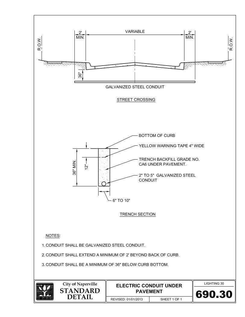
602.7.3 GALVANIZED STEEL CONDUIT – 2 INCH, 3 INCH OR 4 INCH Where underground street lighting cables cross public streets or commercial driveways, all electrical cables and all electrical cables in Unit Duct shall be in an appropriate sized galvanized steel conduit. The galvanized steel conduit shall be placed not less than 3 feet deep.
Section 6: Street Lighting & Traffic Signals Naperville Standard Specification
600-11 REV 05/15/15
602.8 ELECTRICAL CABLE, 600 VOLT The material supplied shall be XLP USE-2, 600 volt cable (colored insulated jacket of black, white, red, and green) of the specified number of conductors and cable size per the IDOT Standard Specifications.
602.8.1 POLE WIRE Pole Wire shall be 1/C No. 10 AWG 600 volt insulated copper conductor, XLP USE-2, stranded in conformance with ASTM B-8 from the luminaire terminal blocks to the pole handhole per IDOT Standard Specifications Sections 817 and 1066.06 for Roadway Lighting pole wire and from the pole handhole to the underground distribution system in a moisture-proof manner. Connection of pole wire to the terminals in the street lighting luminaire is incidental to the installation of the pole wire.
a) Pole wire shall be insulated with cross-linked polyethylene, (XLP) insulation jackets of
black or red or white or green colored insulation. The wire is to run inside the pole and mast arm.
b) For aluminum poles, two 1/C - #10 pole wire conductors in black and white colors will
be used. c) For concrete poles, three 1/C - #10 pole wire conductors in black, white, and green color
will be used. The green conductor will be connected to the ground lug of the luminaire and to the ground lug/ground cable in the base of the pole.
602.8.2 SPLICING Splicing of Electrical Cable shall be in accordance with the IDOT Standard Specifications with the following additional requirements.
a) Splices above grade, such as in poles and junction boxes, shall have a waterproof sealant
and a heat-shrinkable plastic cap. The cap shall be of a size suitable for the splice and shall have a factory-applied sealant within.
b) Additional seal of the splice shall be assured by the application of sealant tape or the use
of a sealant insert prior to the installation of the cap. Either method shall be assured compatible with the cap sealant.
c) Tape sealant shall be applied in not less than one half-lapped layer for a length of at least
1/4 inch longer than the cap length and the tape shall also be wrapped into the crotch of the splice. Insert sealant shall be placed between the wires of the splice and shall be positioned to line up flush or extend slightly past the open base of the cap.
602.9 LIGHTING CABLE FUSE KITS In-line fuse holder(s) and fuse(s) on all leads shall be in accordance with the IDOT Standard Specifications and as follows:
Section 6: Street Lighting & Traffic Signals Naperville Standard Specification
600-12 REV 05/15/15
a) Fuse holders of the in-line quick disconnect breakaway type shall be used on all light pole installations in the base of each lighting standard. The fuse holder shall have a minimum rating of 30 amps and be sized for 13/32 inch x 1 1/2 inch fuses. Fuse holder shall be Edison HEB-AW-RLC-A 30A 600V for load/line and HET-AW-RLC-A for neutral or equal as approved by Engineer.
b) Wires shall be carefully stripped only as far as needed for connection to the device. Over-
stripping shall be avoided. An oxide inhibiting lubricant shall be applied to the wire for minimum connection resistance before the terminals are crimped-on.
c) Crimping shall be performed in accordance with the fuse holder manufacturer’s
recommendations. d) The exposed metal connecting portion of the assembly shall be taped with two half-lapped
wraps of electrical tape and then covered by the specified insulating boot. e) The fuse holder shall be installed such that the fuse side is connected to the pole wire (load
side) and the receptacle side of the holder connected to the line side. f) In-line fuse holder(s) shall be provided on all neutral conductors with a solid slug in place
of the fuse in the base of each lighting standard. g) Fuses for fuse holders on line/load cable to pole wire connection shall be time delay, rated
for 12 ampere, Type MEQ or MEM, or equal. 602.10 STREET LIGHTING HANDHOLES Street lighting handholes shall be used on the far side of any street crossing opposite a street lighting controller or a specified by the Engineer. Street lighting handholes shall be constructed in accordance with the IDOT Standard Specifications with the following provisions:
a) The handhole shall be poured in place concrete with inside dimensions of 21-1/2 inches minimum. Frames and lid openings shall match this dimension. Hinged lids shall not be used. The legend “STREET LIGHTING” shall be cast in the lid.
b) All conduits shall enter the handhole at depth of at least 30 inches. c) Cable hooks are required, one per side of handhole. All cable hooks are to be hot-dipped
galvanized in accordance with AASHTO Specification M111.
602.11 COMPOSITE CONCRETE JUNCTION BOX Composite concrete junction boxes shall be constructed in accordance with the provisions of the IDOT Standard Specifications and for the connecting conduits into the junction box. The size shall be a minimum of 11 inches x 18 inches x 18 inches deep PC Style gasketed box with open base. The junction box shall be a:
Section 6: Street Lighting & Traffic Signals Naperville Standard Specification
600-13 REV 05/15/15
a) 4 bolt cover by Quixote Compolsolite with a design load of 8000 pounds or greater, or, b) 2 bolt cover by Synertech with a design load of 10,000 pounds or greater,
unless otherwise specified in the plans and approved by the City Engineer. The cover shall bear a legend of “STREET LIGHTING”. There shall be no holes cut into the sides of the junction box without approval from the Engineer. 602.12 GROUNDING Street lighting equipment shall be grounded in accordance with the IDOT Standard Specifications with the following provisions:
a) Metal poles installed on metal foundations do not require a separate ground rod installation. b) Metal light poles installed connected directly to a NDPU service point must have a white
1/C #10 XLP/USE-2 bonding jumper installed between the pole grounding lug and the neutral conductor.
c) Metal light poles installed on a controller circuit do not require a separate bonding jumper
at each pole. 602.13 GROUND ROD Installation of ground rods are required for the grounding of individual electrical service non-metallic street lighting poles/foundations and for supplementing the equipment grounding system via connection at poles or other equipment throughout the street lighting system. All materials and work shall be in accordance with Article 250 of the NEC.
a) Grounding of concrete street light poles shall be by a 3/4 inch x 10 foot ground rod in accordance with the IDOT Standard Specifications, and connection by colored covered cable in accordance with the provisions of the IDOT Standard Specifications to the lighting system green 1/C #6 ground cable.
b) Grounding for concrete foundation street lighting poles shall be by installation of the
ground rod in the concrete foundation projecting out into the ground or by installation adjacent to a concrete foundation for a street lighting pole, and connection by bare cable in accordance with the provisions of the IDOT Standard Specifications to the lighting system green 1/C #6 ground cable.
c) Grounding for controller cabinets shall be by installation of a ground rod in the concrete
foundation projecting out into the ground and connected to the ground terminal bar in the cabinet by bare cable in accordance with the provisions of the IDOT Standard Specifications.

Section 6: Street Lighting & Traffic Signals Naperville Standard Specification
600-14 REV 05/15/15
d) Where connections to ground rods are made to insulated conductors, the connection shall be wrapped with at least four layers of electrical tape extending 6 inches below finished grade.
602.14 STREET LIGHTING CONTROLLER A street lighting controller shall be constructed as part of any lighting system for four or more street lights. This item shall consist of furnishing and installing a roadway lighting electrical control cabinet complete with foundation and wiring for control of roadway lighting as specified herein and as directed by the City Engineer. Unless otherwise indicated, the cabinet, including all components, shall be new. Controllers located in the Central Business District shall provide separate circuits and contactors for roadway, pedestrian, and holiday lights as specified in the City of Naperville CBD specifications.
602.14.1 STREET LIGHTING CABINET
a) The cabinet shall be a ground mounted and shall be 30 inches minimum width by 48 inches in height by 17-3/4 inches minimum depth (IDOT Type III) and shall be fabricated from aluminum alloy of 0.125 inches in thickness. The surfaces shall have a smooth, natural aluminum finish.
b) The main door is of NEMA type construction with a cellular neoprene gasket which is
rain and dirt tight without louver slots in the lower portion of the door to exclude the entry of moisture, dirt, and insects. Hinges are 14 gauge stainless steel. Standard equipment includes a three point locking system which secures the door at the top, bottom, and center. A Corbin lock with two keys is also furnished. The main door is equipped with a two position door stop, one stop at 90 degrees and the other at 120 degrees. A nameplate with the legend “City of Naperville Street Lighting” shall be fabricated and mounted on the main door. Below the nameplate, a 2nd plate with the legend “Contact the Department of Public Works at (630) 420-6187 to report problems” shall be mounted.
c) The cabinet shall be equipped with a vent in the underside of the overhang above the
cabinet door, which is designed to resist moisture, dirt, and insects. d) The equipment mounting panel shall be made of 1/4 inch minimum non-asbestos,
inorganic, non-conducting material and shall be drilled and tapped for front mounting of the equipment. The panel shall be easily installed and removed from the front of the panel.
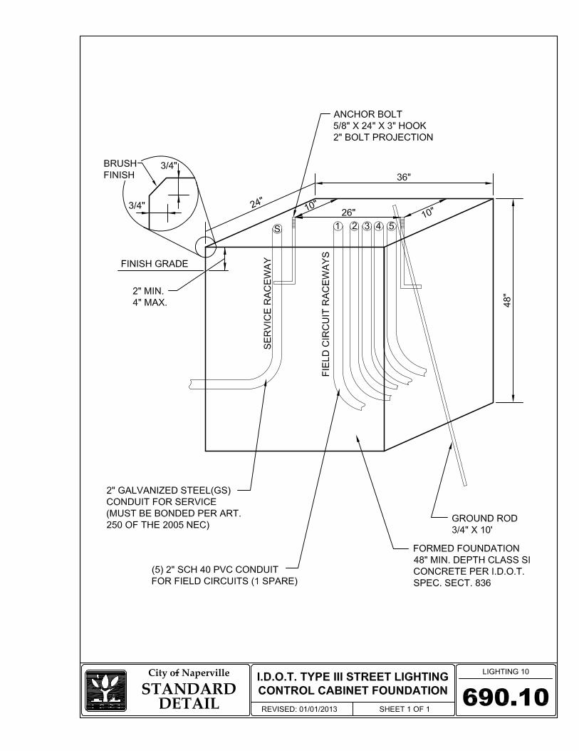
602.14.2 CONTROLLER FOUNDATION
a) The foundation shall be furnished and installed in place per the dimensions shown on the
attached Street Lighting Controller Cabinet Foundation Detail for Type III Cabinet.
Section 6: Street Lighting & Traffic Signals Naperville Standard Specification
600-15 REV 05/15/15
b) The anchor bolts shall comply with ASTM A576. The top 6 inches of the anchor bolts shall be hot dipped galvanized steel according to ASTM 153. The nuts and lock washers shall be galvanized also. There shall be a minimum of 4 anchor bolts for each controller.
c) The foundation shall include a 2 inch galvanized steel conduit raceway for the service,
four 2 inch rigid plastic raceways (for 1-1/4 inch unit duct) for the field circuits, and one spare raceway of 2 inch rigid plastic.
d) The foundation shall include a copper coated steel ground rod 3/4 inch in diameter and 10
feet in length, including copper bonding wire as shown in Street Lighting Controller Cabinet Foundation Detail for Type III Cabinet.
e) For the conditions of controller cabinet being a replacement/retrofit of an existing
pedestal mounted street light controller, the foundation will include removal of the top 6 inches of the existing foundation, expose the remaining existing concrete foundation to a depth of 48 inch below the finished grade of the new foundation, setting of four anchor bolts into the remaining foundation at a depth to be a minimum of 12 inches below the finished grade of the new foundation to tie the existing foundation into the new ground mount cabinet foundation. Installation of new foundation includes raceways noted in c) above.
602.14.3 CONTROLLER OPERATION
a) The street light controller shall control and provide over current protection for up to eight
individual street light circuits. Each circuit is to be protected by the use of individual thermal-magnetic circuit breakers. Provisions shall be made for connection of up to #6 stranded copper conductors for the individual circuits.
b) The street light controller shall be actuated by a remotely mounted photocell, which will
operate through an auxiliary on-delay relay to pick up the controller’s main mechanically held contactor. The operation of the photocell will insure that the street light circuits are energized during nighttime hours and de-energized during daytime hours.
602.14.4 CONTOLLER EQUIPMENT The controller must include the following:
a) 100 ampere main breaker, 2 pole, 240 volt, JDB 2100 b) 100 ampere contactor, 2 pole, single throw, electrically operated and mechanically held
remote switch, 120 volt, ASCO 2P, 100 amp, model number 920210031. c) Eight 35 ampere, 1 pole circuit breakers, 120 volt, “I-Line”. d) Control breaker, 1 pole, 15 amp, WE GC1015
Section 6: Street Lighting & Traffic Signals Naperville Standard Specification
600-16 REV 05/15/15
e) Relay, DPDT, 120 v, on-delay, Magnacraft W211ACPSOX-7 f) 15 ampere, HOA switch, 120 volt, Square D Manual Return KS43FBH13 NEMA 4X
enclosure g) SPST 20 ampere switch h) Incandescent light fixture of the enclosed and gasketed type, Crouse Hinds VXHF15GP i) 20 ampere duplex receptacle, GFCI j) Photocell terminal block k) Thermostat, Grainger 2E552 l) Heating Strip, 150 watt Grainger 2E919 (shall not be mounted to equipment mounting
panel) m) Surge Protector, Square D SP-11100 n) Neutral bus bar, 1/4 inch by 1 inch by 12 inches, color coded white, labeled “neutral” o) Ground bus bar, 1/4 inch by 1 inch by 12 inches, color coded green labeled “ground”. p) Secondary Pedestal shall be installed by the Naperville Department of Public Utilities -
Electric
602.14.5 SERVICE TO STREET LIGHTING CONTROLLER
a) This section includes the installation of conduit and wire from the secondary pedestal to the street lighting controller. The secondary pedestal is installed by the Naperville Department of Public Utilities – Electric at a minimum of 5 feet from the NDPU-E service point.
b) The service wiring from the secondary pedestal to the street lighting controller shall be
3/C - #2 XLP/USE-2 colored insulation of black, red, and white in 2 inch galvanized steel conduit.
c) A metallic threaded bushing with lug shall be installed on the 2 inch galvanized steel
conduit for the service and connected by a 1/C #6 XLP/USE-2 cable (green) to the ground rod.
d) A minimum of 8 feet of 4/C-#2 shall be provided at the secondary pedestal for the
purpose of making the connections to the source by NDPU-E. Additionally, 10 feet of “tails” should be included in the service to the street lighting controller.

Section 6: Street Lighting & Traffic Signals Naperville Standard Specification
600-17 REV 05/15/15
602.14.6 BUS BARS All bus bars shall be of a size to handle the rated current of the connected equipment. Exposed bus bars shall be insulated, except for ground and neutral bus bars.
Separate ground and neutral bus bars shall be provided. The ground bus bar shall be copper and mounted on the equipment panel. The neutral bar shall be similar. The heads of the screws shall be painted white for the neutral bar and green for the ground bar.
602.14.7 WIRING AND IDENTIFICATION
a) All wiring shall be of a size to handle the rated current of the connected equipment.
b) Wiring within the cabinet shall be of the size specified for the corresponding service conductors and branch circuits and shall be rated RHH/RHW or MTW, 600 volts.
c) Control and auxiliary wiring shall be a minimum of #10 copper and rated RHH or MTW
with jacket, 600 volt, stranded copper of appropriate colored insulation of red, black, white, and green.
d) All power and control wiring shall be tagged with self-sticking cable markers and shall be
stranded copper. e) All switches, controls and the like shall be identified as to function and position (as
applicable) by means of engraved 2 color nameplates attached with screws. 602.14.8 CIRCUIT BREAKERS
a) All feeders, branch circuits, and auxiliary and control circuits shall have over current protection per the requirements of the NEC and as shown on the engineering plans. The over current protection shall be by means of circuit breakers.
b) Circuit breakers shall be standard UL-listed molded case, thermal magnetic “I-Line”
breakers with trip free indicating handles with terminals adequate for #6 single conductor copper cable.
c) Circuit breakers shall have a UL-listed interrupting rating of not less than 10,000 rms
symmetrical amperes at rated voltage. d) The eight branch circuit breakers shall be as specified on the circuit schematic, unless a
lesser number is specified.

Section 6: Street Lighting & Traffic Signals Naperville Standard Specification
600-18 REV 05/15/15
602.14.9 CONTACTOR(S)
a) The contactor shall be electrically operated, mechanically held, with the number of poles required for the service and with 120 volt operating coil voltage as indicated or otherwise required. Unless otherwise indicated in the engineering plans, the contactor shall be an ASCO 2P, 100 amp, model number 920210031.
b) Contactor(s) shall be complete with a non-conducting inorganic, non-asbestos sub-panel
for mounting. c) Contactor(s) shall be mechanically held, and shall be complete with coil-clearing contacts
to interrupt current through the coil once the contactor is held in position. d) The main contactor contacts shall be double break, silver to silver type. They shall be
spring-loaded and provide a wiping action when opening and closing. The contacts shall be renewable from the front panel, self-aligning, and protected by auxiliary arcing contacts.
e) The line and load terminals shall be pressure type terminals of copper construction and of
the proper size for the ampere rating of the contactor. f) The contactor operating coil shall be rated for nominal 120 volt, single phase. g) Protection from accidental contact with current carrying parts, when operating the
contactor manually, shall be provided. h) Contactors shall be clearly marked to indicate whether they are in the open or closed
position.
602.14.10 AUTO/MANUAL CONTROL
a) The cabinet shall be equipped with automatic and manual operating controls via a one-pole, double-throw switch. The switch shall be premium specification grade, rated for the applied duty, but not less than 20 amperes at 120 volts and shall be mounted in a 4 inch square box with cover.
b) The cabinet control and auxiliary device circuit shall have over current protection as
indicated and as required by NEC. c) Each street lighting controller shall be wired to an individual photocell located on top of
the nearest street light pole. The photocell shall operate at 120 volts, 60 Hertz, AC, and be rated at 1,000 watts. The photocell shall be grounded to the luminaire. The photocell shall be wired to the street lighting controller in unit duct, 1-1/4 inch minimum size, 3/C - #10, 600V, XLP/USE-2 of colored insulation of red, black, and white, if the cabling to the photo-cell cannot be pulled into a field circuit conduit.
Section 6: Street Lighting & Traffic Signals Naperville Standard Specification
600-19 REV 05/15/15
602.14.11 INTERIOR LIGHTING AND RECEPTACLE
a) The auxiliary device circuit shall provide 120 volts single phase to supply the
convenience receptacle and cabinet light. b) The cabinet shall be equipped with an interior, 60 watt incandescent lighting fixture of
the enclosed and gasketed type switched from a single pole, single throw, 20 amperes switch. The switch shall be premium specification grade in a suitable 4 inch box with a cover.
c) The cabinet shall be equipped with a 120 volt, 20 ampere G.F.I. duplex receptacle,
premium specification grade in a 4 inch square box with a cover. d) The cabinet shall be equipped with a heating strip that shall maintain the temperature
within the cabinet at a minimum of 40 degrees Fahrenheit.
602.14.12 TESTING OF THE ASSEMBLED CABINET Prior to shipment of the completed cabinet, the control cabinet shall be tested for load, short circuits and complete operation of the cabinet as specified herein and as shown on the plans.
602.14.13 ACCEPTANCE AND CONNECTION Upon final inspection and approval of the street light system by the Naperville Departments of Transportation and Engineering and Public Utilities, NDPU-E will provide all labor and material necessary to provide 120/240 volt, two-phase, electrical service connection at the service point.

Section 6: Street Lighting & Traffic Signals Naperville Standard Specification
600-20 REV 05/15/15
603 CONSTRUCTION REQUIREMENTS 603.1 TRAFFIC SIGNAL SYSTEMS CONTRACTOR PRE-QUALIFICATIONS All contractors working on traffic signals under City of Naperville jurisdiction shall be pre-qualified for traffic signal work with the Illinois Department of Transportation in accordance with the IDOT Standard Specifications.
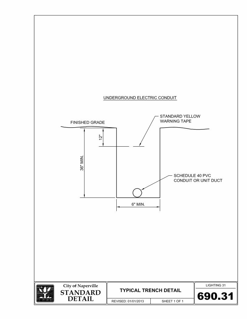
603.2 TRENCH AND BACKFILL FOR ELECTRICAL WORK Constructing a trench for the accommodation of conduit and backfilling shall be carried out in accordance with the IDOT Standard Specifications except that the 3rd paragraph of Article 819.04 is deleted. Backfill material shall be CA-6 under all paved surfaces.
The trench shall not be less than 36 inches deep with cable installation at a minimum of 32 inches in depth.
603.3 YELLOW WARNING TAPE OVER STREET LIGHTING CABLE A 4 inch wide yellow warning tape shall be installed over the street light duct at all locations where new cable is placed by the trench and backfill method. The warning tape shall be placed approximately 1 foot below grade. 603.4 TRAFFIC SIGNAL SYSTEM SERVICE INSTALLATION Electrical service for traffic signals is to be provided by the City of Naperville Department of Public Utilities - Electric (NDPU-E) from a pad-mounted transformer. The Contractor shall install a meter socket, Milbank #U8980-0-KK supplied by the Contractor. The Milbank shall be located as shown in the plans. The meter shall be supplied and installed by NDPU-E. Standard service shall be 120/240 volt, two phase, 3 wire between the service point and the Milbank (meter) and shall be 120 volt, one phase, 4 wire between the Milbank (meter) and the traffic signal controller cabinet. The contractor is to contact NDPU-E Engineering Department for Specifications if another service voltage is required. The Contractor shall install #6 CU, STR, XLP, U.S.E., 600 volt cable (color coded black, white, and red) in 2 inch galvanized steel conduit between the meter socket and the service connection point. For underground service connections, the service conductors and conduit shall extend to within 2 feet of the service connection point. The Contractor shall coil 8 feet of 3C cable at the connection point for NPDU-E personnel to make the hook-up. The conductor shall be sealed, for overhead service connections, unit duct and service conductors shall be attached to utility pole and up to a minimum of ten feet above grade. The service conductors shall be coiled to provide a minimum of 20 feet of available conductor. The conductor shall be sealed. A schematic detail drawing illustrating the connection to the Milbank and the traffic signal controller is shown as detail.
Section 6: Street Lighting & Traffic Signals Naperville Standard Specification
600-21 REV 05/15/15
The entire installation will be grounded in a manner satisfactory to NDPU-E and to the City Engineer.
Section 6: Street Lighting & Traffic Signals Naperville Standard Specification
600-22 REV 05/15/15
604 INSPECTIONS AND TESTING 604.1 STREET LIGHTING SYSTEMS New street lights must be inspected by the city’s Inspection Team prior to their acceptance. The contractor should contact the Transportation, Engineering and Development Business Group Inspection Dispatch at (630) 420-6082 to schedule an inspection. The inspection must be scheduled at least 48 hours in advance. 604.2 TRAFFIC SIGNAL SYSTEMS
604.2.1 CONCRETE All concrete work associated with the installation of a traffic signal must be tested by the contractor.
604.2.2 FIELD INSPECTION A field inspection is required prior to maintenance transfer of a signal from the contractor to the city. It is the intent to have all electrical work completed and equipment field tested by the vendor prior to the city's "turn-on" field inspection. If in the event the Engineer determines work is not complete and the inspection will require more than two hours to complete, the inspection shall be cancelled and the contractor will be required to reschedule at another date. The maintenance of the traffic signals will not be accepted until all punch list work is corrected and re-inspected.
When the road is open to traffic, except as otherwise provided in the IDOT Special Provisions, the contractor may request a turn-on and inspection of the completed traffic signal installation at each separate location. This request must be made to the City Engineer at (630) 420-6100 a minimum of 7 working days prior to the time of the requested inspection. The city will not grant a field inspection until written certification is provided by the contractor and the equipment has been field tested and the intersection is operating according to contract requirements. The city's facsimile number is (630) 305-5986.

Section 6: Street Lighting & Traffic Signals Naperville Standard Specification
600-23 REV 05/15/15
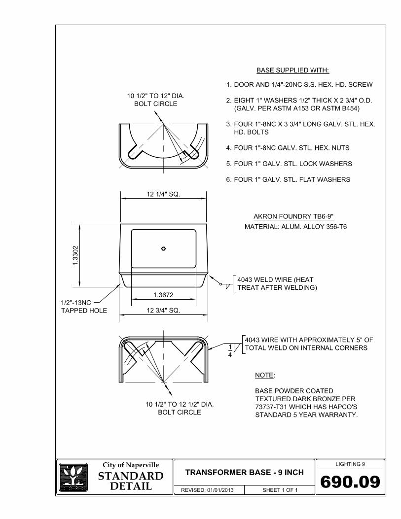
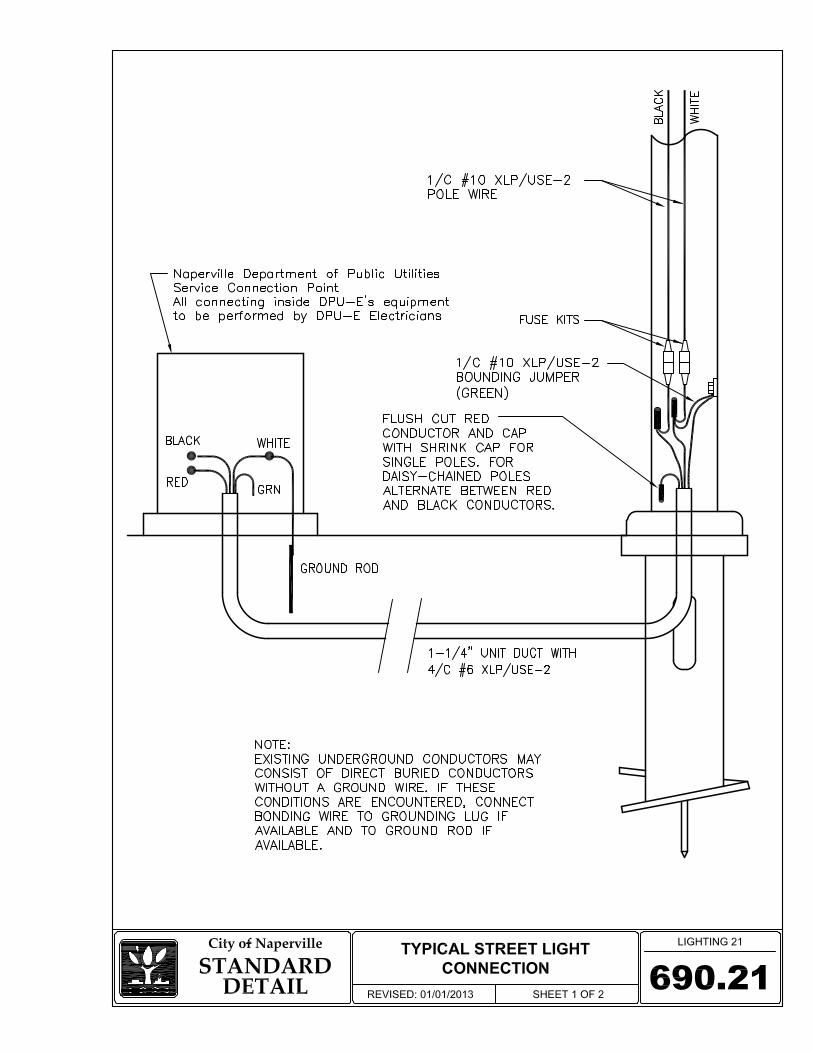
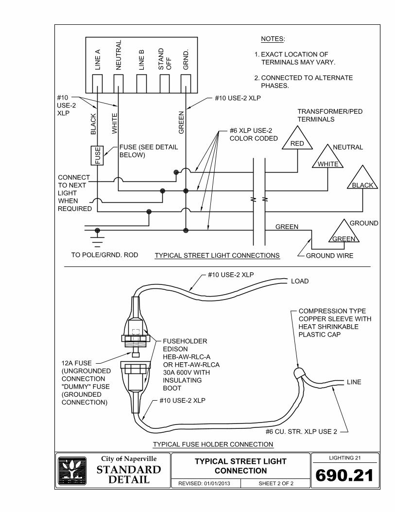
690 STANDARD DETAILS Structures 690.01 Truss Arm Street Light Detail – 32 Foot 690.02 Truss Arm Street Light Detail – 40 Foot 690.03 Davit Arm Street Light Detail – 23 Foot 690.04 Davit Arm Street Light Detail – 32 Foot 690.05 “Cobra Head” Type Luminare Detail 690.06 Salem Type Luminaire Detail – 23 Foot 690.07 Helix Type Pole Foundation Detail 690.08 Concrete Pole Foundation Detail (2 sheets) 690.09 Transformer Base – 9 Inch 690.10 I.D.O.T. Type III Street Lighting Control Cabinet Foundation Electrical 690.21 Typical Street Light Connection (2 sheets) 690.22 Street Lighting Controller Schematic Conduit & Trenching 690.30 Electric Conduit Under Pavement 690.31 Typical Trench Detail 690.99 COMMON NAMES All standard details in this section may be referred to by a common name in associated construction documents. The common name shall be “LIGHTING xx” where the xx is the section of the detail number to the right of the decimal point. For instance, Detail #690.07 Helix Type Pole Foundation Detail may also be referred to as “LIGHTING 7”.