Embed Size (px)
Citation preview
209
SECTION 501 PORTLAND CEMENT
CONCRETE PAVEMENT 501.01 DESCRIPTION
This work is the construction of PCCP on a prepared subgrade or base course.
501.02 MATERIALS
501.02.1 Concrete Furnish concrete in accordance with Section 551 for Class Pave concrete. A. Cement. Furnish Type I or II portland cement listed on the QPL, in accordance with
Subsection 551.02.1. B. Air-entraining Admixtures. Furnish air-entraining admixtures in accordance with
Subsection 551.02.2. C. Aggregates. Furnish aggregates in accordance with Subsection 701.01. D. Water. Furnish water for concrete in accordance with Subsection 713.01.
501.02.2 Reinforcing Steel Steel-wire fabric and steel bar mat sizes and dimensions are specified in the contract. Furnish steel-wire fabric reinforcement in flat sheets. Furnish bar mats and bars of structural or intermediate grade, as specified in the contract. Furnish all reinforcing steel in accordance with Subsection 711.01.
501.02.3 Dowel Bars and Sleeves Furnish Grade 40 plain round dowel bars in accordance with AASHTO M 31. Bar dimensions and placement in the pavement are specified in the contract. Do not use bars having burrs or other deformation that restrict slipping in the concrete. Before delivery to the project, coat one-half the length of each dowel bar with one coat of
zinc or tar paint. Furnish sleeves for dowel bars meeting the contract requirements.
501.02.4 Tie Bars Furnish Grade 40 deformed steel bars in accordance with Subsection 711.01. The length,
size, and spacing of the bars are specified in the contract.
501.02.5 Expansion Joint Filler and Joint Sealing Material Furnish expansion joint filler and joint sealing material listed on the QPL and in accordance
with Subsection 707.01.
501.02.6 Curing Compound Furnish Type 2 curing compound in accordance with Subsection 717.01.3.
501.03 CONSTRUCTION REQUIREMENTS
501.03.1 Equipment A. General. Do not begin paving operations until all equipment and tools for the pavement
construction are available at the site. Ensure the equipment is in good mechanical condition, adjustment, design, and
capacity. Adjust, repair, or replace equipment failing to produce the specified work. Use handling, batching, mixing, and concrete transporting equipment in accordance
with Section 551 and the following.
501 – PORTLAND CEMENT CONCRETE PAVEMENT 2014 EDITION
210
Use batch plants for projects having 300 cubic yards (229.5 m3) or more PCCP that proportion aggregates and cement by weight using automatic and interlocked proportioning devices.
Use non-agitating hauling equipment with smooth, mortar-tight metal bodies that completely discharge the concrete at a uniform rate without segregation. Provide covers when necessary to prevent the concrete from drying out or being exposed to weather-related moisture.
Use belly-dump trucks only with the Project Manager’s written approval. Remove and dispose of concrete remaining in haul units before reloading with fresh
concrete. B. Stationary Side Forms. Use metal side forms strong enough to resist displacement from
concrete and mechanical equipment pressures. Use flexible or curved forms for curves with 100-foot (30.5 m) radii or less. Forms must:
1. Hold abutting sections in alignment; 2. Be adjustable for vertical and horizontal curvature; 3. Have a minimum depth equal to the specified concrete edge thickness; 4. Not have horizontal joints; 5. Have a base width greater than or equal to the depth; 6. Have at least 3 staking points for each 10 feet (3 m) of length that securely lock to the
form stake; and 7. Have flange braces and staking pockets that extend outward on the base at least ⅔
the height of the form. Use wooden forms only with the Project Manager’s written approval. Include in the
request to use wooden forms complete details showing they meet the requirements for steel forms regarding strength, lines, grades, and depth.
Do not use forms in poor condition in the work. Repaired forms must be inspected and approved before use.
C. Placing, Consolidating, and Finishing Equipment. Place, consolidate, and finish concrete in accordance with Section 551.
Operate only rubber-tired equipment on adjacent pavement. Pad crawler units to prevent pavement damage.
Keep the adjacent pavement and form tops clean to provide good contact with tires or crawler units. 1. Slip-form Pavers. Use slip-form pavers having automatic controls for longitudinal
and transverse grade from continuous wire control lines. Maintain the control wire tension, support interval, and sensor operating pressure
to prevent control wire deflection in excess of 3⁄16-inch (5 mm) below supports at mid-span. Immediately stop paving operations when deflection exceeds 3⁄16-inch (5 mm) and resume once corrected.
Use self-propelled slip-form pavers to place and finish the concrete that are capable of negotiating all grades without external tractive force.
Equip the slip-form paver with an auger or other approved strike-off device to distribute the concrete to a uniform depth ahead of the screed.
Use sliding forms that are laterally rigid to prevent spreading. Use slip-form pavers that consolidate the plastic concrete by internally vibrating
the full paving width and depth. Use transverse vibrating units that do not project outside the specified paving section thickness and are positioned ahead of the screed a minimum distance equal to the pavement thickness. A series of longitudinal
2014 EDITION PORTLAND CEMENT CONCRETE PAVEMENT – 501
211
vibrating units may be used as an alternate. Vibrators may be the immersed tube type or a series of equally spaced longitudinal vibrating units.
The maximum spacing of each unit in a series of longitudinal units is 24 inches (610 mm) measured center-to-center of the units.
Each vibratory unit must provide at least 7000 vibrations per minute with the amplitude visibly perceptible on the concrete surface within 1-foot (305 mm) of the entire length of the vibrating unit. Equip the paver with a tachometer or other approved device for measuring the actual vibration frequency.
2. Auxiliary Finishing Equipment. Use finishing equipment behind the slip-form paver that automatically maintains alignment from an external reference.
Provide hand floats, edging tools, and other hand-finishing equipment to finish the surface as specified. Steel concrete hand tools are prohibited from being used on the project as a finishing aid.
3. Stationary Side Form Method. Submit details for all equipment proposed for spreading, strike-off, consolidating, screeding, and floating before use.
4. Roadbed Planers. Equip the roadbed planer with adjustable steel cutting edges mounted in a rigid frame to trim the roadbed to the specified elevation and crown under all operating conditions. The planer wheels must ride on the forms or adjacent pavement.
5. Concrete Spreaders. Use a self-propelled spreader that uniformly spreads the concrete between forms and has an adjustable blade or head for striking off the concrete to the required height and crown.
6. Vibrators. Use full-width concrete slab vibrators of the surface pan type or the internal type with immersed tube or multiple spuds.
The vibrators may be mounted on the spreader, the finishing machine, or on a separate carriage.
Do not allow the vibrators to come in contact with the joint load transfer devices, the subgrade, or side forms.
Use vibrators in accordance with the following: • Surface vibrators having a minimum frequency of at least 3,500 impulses per
minute. • Tube vibrators with a minimum frequency of at least 5,000 impulses per
minute. • Spud vibrators with a minimum frequency of 7,000 impulses per minute. • Hand-operated or machine-mounted spud-type internal vibrators next to forms
having a minimum frequency of 3,500 impulses per minute. 7. Bridge Deck Finishing Machines. Use transverse-finishing rotating drum bridge
deck finishing machines when stationary side forms are allowed. 8. Mechanical Floats. Use mechanical floats that produce a surface true to the required
crown and smoothness, free from honeycomb or excessive mortar. Ensure the float makes accurate incremental adjustments to the required crown
without interrupting the float operation. The mechanical float may be self-propelled or attached to the rear of the
transverse finishing machine.
501.03.2 Pre-paving Conference Attend a pre-paving conference, conducted by the Department, to be held at least 24 hours
before paving starts.
501 – PORTLAND CEMENT CONCRETE PAVEMENT 2014 EDITION
212
The conference topics will include equipment, construction methods, specification requirements, and lines of communication.
The conference must include the foreman, other Contractor personnel that will supervise the concrete paving operations and key Department inspection personnel.
501.03.3 Aggregate Sampling and Testing Furnish aggregates that meet the gradation requirements, fineness modulus, and deleterious
material limits specified in Subsection 701.01. Provide all sampling and testing to meet these requirements during aggregate production.
501.03.4 Aggregate Production Produce aggregate in accordance with Section 551. Produce and stockpile at least ⅓ of the quantity of each size aggregate necessary to
produce the plan quantity of PCCP before paving operations begin.
501.03.5 Acceptance of Aggregate A. Sampling and Testing. The Project Manager will determine when samples are taken
and will test the aggregate for acceptance. Furnish and operate the aggregate sampling devices, witnessed by the Project
Manager. Take samples at a point immediately before the aggregates are combined and enter the mixer, witnessed by the Project Manager. Samples may be split to a minimum 50 pounds (23 kg). Furnish the samples to the Project Manager immediately after sampling.
Acceptance samples will be randomly selected. The approximate quantity represented by each sample is specified in MT 601. Additional samples may be selected and tested.
B. Lot Size. The concrete quantity in each day’s production constitutes a lot whenever production schedules and material continuity permit.
The Project Manager may establish a lot consisting of the quantity represented by any number of consecutive random samples from 3 to 7 inclusive if the Project Manager determines it is necessary due to production runs, significant material changes, or other unusual characteristics of the work.
C. Acceptance. PCCP is evaluated for price adjustment on a lot-by-lot basis in accordance with Subsection 105.03.2, when deviation from specified aggregate gradation limits, fineness modulus limits for fine aggregate, or percent passing the No. 200 (0.075 mm) sieve for coarse aggregate occurs on 1 or more tests for a lot.
Payment for a lot where a price reduction applies in accordance with Subsection 105.03.2 is calculated using the following formula:
Price Reduction = Contract Unit Price x 0.40 x P/100 x Lot Quantity
Where: P = the percent reduction in contract unit price as defined in
Subsection 105.03.2. Lot Quantity = the plan quantity in cubic yards (m3) or square yards (m2) of the
pavement section where the lot was placed.
501.03.6 Mixing Mix concrete in accordance with Subsection 551.03.3.
501.03.7 Transporting Concrete Transport concrete in equipment in accordance with Subsections 501.03.1 and 551.03.4.
2014 EDITION PORTLAND CEMENT CONCRETE PAVEMENT – 501
213
501.03.8 Placing and Finishing Concrete Submit a plan for placing and curing PCCP to the Project Manager for approval a minimum
of 15 business days before the start of paving work. Include specific detail of joint layout at manholes, water valves, drop inlets, monument boxes and other structures in the PCCP section.
Place and finish concrete using either the slip-form method or the stationary side form method using bridge deck finishing equipment.
Place the fresh concrete on the prepared roadbed as close as possible in front of the paving machine to minimize concrete handling. Do not routinely use front-end loaders or other equipment at the paver for moving the fresh concrete once it’s placed on the roadbed.
Place concrete hauled in non-agitating equipment within 45 minutes from when the ingredients were charged into the mixer. Dispose of concrete hauled in non-agitating equipment that does not meet slump requirements at Contractor expense.
Place concrete hauled in agitator trucks within the time limits in Subsection 551.03.4(A). Distribute the concrete to the specified slab thickness, with the finished surface at the
specified grade, once the concrete is consolidated and finished. Do not use vibrators to distribute concrete. Place concrete only after the foundation course or subgrade has been approved by the
Project Manager. Prepare the foundation course ahead of the paving operation equal to the anticipated daily
production. Place concrete around manholes or other structures once the structures are brought up to
the required grade and alignment. Dampen the base or subgrade with a fine water mist immediately before placing concrete.
Do not permit free-standing water to puddle on the surface. If concrete placing is delayed or stopped in excess of 1 hour, construct an emergency
transverse construction joint as directed. Except for emergency transverse joints, do not construct a joint at any location other than as
directed or specified. Construct the pavement in full lane widths in a single operation. Construct longitudinal joints between lanes or sections in accordance with Subsection
501.03.13(F). Do not place concrete in longitudinal sections until the adjacent slab is 14 days old or has
reached a minimum compressive strength of 2,000 psi (13,800 kPa), determined by testing the standard cylinders cured under the same environmental conditions as the slab.
A. Slip-form Method. 1. General. Place the concrete with a slip-form paver in accordance with Subsection
501.03.1(C) that spreads, consolidates, screeds, and float-finishes the fresh placed concrete in 1 pass.
Operate the slip-form paver to maintain a continuous, forward movement. Ensure all concrete mixing, delivering, and spreading provides uniform progress without stopping and starting the paver. If it is necessary to stop the paver, immediately stop the vibrators and tamping.
Maintain a uniform consistency in the concrete with a slump of 1 to 2-inch (25 - 50 mm).
The paver may be set to form a 3-inch (75 mm) or less battered edge while maintaining the top riding surface at the specified width.
Apply additional hand vibration at construction joints as required for consolidation. 2. Finishing. Finish the concrete surface to meet Subsection 501.03.14.
501 – PORTLAND CEMENT CONCRETE PAVEMENT 2014 EDITION
214
Correct any pavement edge slump, excluding specified edging, exceeding ¼-inch (6 mm) before the concrete has hardened.
If the edge slump on any 1-foot (305 mm) or longer length of hardened concrete exceeds 1-inch (25 mm), remove and replace the entire panel between the transverse and longitudinal joints.
Before the initial concrete set, round the pavement edges on each side of the transverse expansion joints, formed joints, transverse construction joints, and emergency construction joints to the required radius. Construct a well-defined, smooth, dense mortar finish radius.
Hand finishing is permitted only for finishing sections with narrow irregular dimensions and to finish any concrete already deposited on the grade should a machinery breakdown occur.
Grind high spots exceeding ¼-inch (6 mm) using approved methods. Fill low spots exceeding ¼-inch (6 mm) with an approved epoxy-bonded grout as directed.
B. Stationary Side Form Method. 1. Preparation of Subgrade or Foundation Course. Once the roadbed is finished and
compacted in accordance with Section 203, trim, shape, and compact the subgrade or foundation course in accordance with Section 301 to the specified lines, grades, and cross sections.
Extend the finished subgrade 2 feet (610 mm) beyond each side of the planned pavement width.
Once the forms are set, re-shape and re-compact all disturbed subgrade or foundation course using rollers or compactors working between the fine grading equipment and the paver.
Test the subgrade or foundation course in advance of the paver for section and grade using an approved template. Mount the template on visible rollers with the tooth edge conforming to the required shape of the subgrade when riding vertically on the forms. Remove excess material and fill low areas to the finish elevation with subgrade or foundation material and compact to the specified density.
Maintain the finished subgrade or foundation course in a smooth, compacted, undisturbed condition until the pavement is placed.
Moisten the subgrade or foundation course as specified in Subsection 501.03.8 when placing the concrete.
2. Form Setting. Do not permit the forms to deviate more than ⅛-inch (3 mm) from the true plane of the form face or top. Do not permit the forms to warp, bend, or kink. Clean and oil forms before each use.
Cut the compacted foundation course or the subgrade to grade providing firm contact for each form for its entire length at the specified grade. Fill low areas to grade in ½-inch (13 mm) lifts or less for 18 inches (455 mm) on each side of the base of the form and compact to the specified density. Settlement or springing of forms under the finishing machine is not allowed.
The forms will be checked for alignment and grade. Make any corrections before placing the concrete.
Correct unstable or disturbed forms or foundation courses and re-check the forms.
Prepare the foundation course and forms ahead of the paving operation equal to the average daily production.
2014 EDITION PORTLAND CEMENT CONCRETE PAVEMENT – 501
215
Leave the forms in place at least 12 hours after the concrete has been placed unless earlier removal is necessary to permit sawing of transverse weakened plane joints.
Exercise care in removing forms to avoid damage to the pavement edges. 3. Strike-off and Consolidation. Strike-off, screed, and consolidate the concrete with
mechanical equipment to the specified crown and cross section providing a uniform surface texture. Avoid prolonged work over any area.
Maintain a uniform ridge of concrete ahead of the front screed of the finishing machine except when making construction joints.
4. Floating. Following strike-off and consolidation, finish the concrete surface with a mechanical float in accordance with Subsection 501.03.1(C)(8).
5. Finishing. Finish the concrete surface to meet Subsection 501.03.14(A) or (B). C. Final Surface Finish. Hand-float the surface only as needed to produce a uniform
surface and sharp corners. Adding finishing water to unfinished concrete is prohibited. Do not use excess mortar to build up slab edges or round the slab corners. Before the concrete’s initial set, work the pavement edges along each side of transverse isolation joints, transverse construction joints, and fixed forms to produce a ¼-inch (6 mm) continuous radius and a smooth, dense mortar finish. Check the surface of the fresh concrete with a long-handled straightedge that is 10 feet (3 m) or longer. Remove high areas indicated by the straightedge.
D. Texturing. After surface finishing, texture all concrete surfaces within the travel lanes. Use either hand operated or mechanical tools to produce a uniform texture that conforms to the dimensions shown in the contract.
For artificial carpet and burlap drag, furnish carpet or burlap that is long and wide enough to cover the entire pavement width and that produces a uniform texture. Clean drag periodically to remove encrusted mortar or replace with new burlap or carpet.
Meet an average surface texture of 0.040 to 0.060-inch (1 - 1.5 mm), as measured by MT 113 (sand patch test).
If repair of high spots or low spots results in surface texture loss, repair the affected area to the specified texture at the Contractor’s expense. 1. Design Speed Greater than 50 MPH (80 km/h). Produce the final surface finish with
transverse tining, followed by longitudinal artificial carpet or burlap drag. Space transverse tines randomly as follows: • Minimum spacing ½-inch (13 mm); • Maximum spacing 1½-inch (38 mm); and • No more than 50% of the tines apart by more than 1-inch (25mm). Use tines that are ⅛-inch (3 mm) wide, with a tolerance of ± 0.02 inch (± 0.5 mm)
and apply them to a depth of ⅛ to ¼-inch (3 - 6 mm) (provided minimum dislodging of the aggregate particles result).
2. Design Speed Less than 50 MPH (80 km/h). Produce the final surface finish by broom texturing, followed by a longitudinal artificial carpet or burlap drag.
Produce a uniform texture with corrugations 1⁄16-inch (1.5 mm) deep.
501.03.9 Protection of Concrete from Rain Maintain materials at the project site to protect all un-hardened concrete surfaces from rain. When rain appears imminent, stop paving operations and cover all surfaces of the un-
hardened concrete with the protective covering.
501 – PORTLAND CEMENT CONCRETE PAVEMENT 2014 EDITION
216
501.03.10 Evaluation and Repair of Rain-damaged Concrete Follow The American Concrete Paving Association Technical Bulletin No. 17 for the
evaluation of and acceptable repair methods for rain-damaged concrete. All protective, remedial, and corrective work to produce acceptable pavement is at Contractor
expense.
501.03.11 Curing A. Membrane. After the concrete is finished and the free water has left the surface, seal the
entire surface area by machine spraying a uniform application of curing compound in accordance with Subsection 501.02.6.
Apply the curing compound following the manufacturer’s recommendations before surface hair checking develops.
Do not apply curing compound to the inside faces of joints to be sealed. If the groove coverage is not complete after the first application, apply a second
coverage in the opposite direction from the first. Apply the second application within 30 minutes of the first application.
Ensure the equipment controls the curing compound application rate and uniformity. Use the coverage rate of 1 gallon per 150 square feet (0.27 L/m2) or follow the manufacturer’s recommendations.
Re-apply membrane curing compound to areas protected for less than 72 hours and that are damaged by sawing, rain, or other causes.
B. Other Methods. The Contractor may submit for approval, other curing methods.
501.03.12 Handling and Placing Reinforcement Keep reinforcing steel clean, rust free, straight and distortion free, placed and held in position
as specified. Store reinforcing steel out of the weather, distributing only the steel needed for immediate
placing within the work. Assemble and place reinforcement for bar mats as specified. Maintain bar mat placement
during concreting operations. Tie all intersections. Lap all adjacent ends at least 40 bar diameters.
501.03.13 Joints Construct the joints as shown in the contract. Submit an alternate plan for longitudinal and
transverse joint layout with details that are determined by Contractor sequencing to the Project Manager for approval a minimum of 15 business days before the start of paving work.
A. Transverse Expansion Joints. Construct transverse expansion joints in accordance with the contract.
B. Expansion Joints at Structures. Construct and seal joints between concrete approach slabs and structures or concrete pavement as specified.
C. Transverse Construction Joints. Make transverse construction joints as detailed in the contract, at the end of each day’s run, or where concrete work is interrupted for more than 1 hour.
Form the joint using a clean plank cut to the plan cross section with an attached beveled strip to form a key-way. Remove the header and clean excess concrete on the subgrade and joint face before placing fresh concrete against the joint.
D. Transverse Contraction Joints. Saw transverse contraction joints to the specified width, depth, and spacing using a power-driven gang saw with at least 4 separate blades.
Saw initial or “control” transverse contraction joints at 54-foot (16.5 m) intervals or another multiple of the specified joint spacing that reduces uncontrolled cracking with the
2014 EDITION PORTLAND CEMENT CONCRETE PAVEMENT – 501
217
least number of initial contraction joints. Saw initial contraction joints as soon as possible after the concrete is placed. Do not permit the saw to tear or ravel the adjacent concrete. Saw the remaining contraction joints typically within 24 to 48 hours after concrete is placed.
Be responsible for determining joint-sawing methods, sequences, and timing to prevent random cracking. Immediately revise methods that cause random cracking. Repair or replace concrete defects resulting from errors in the work methods at Contractor expense.
Repair or replace broken slabs, random cracks, nonworking contraction joints near cracks, and spalls along joints and cracks in accordance with Subsection 501.03.15.
Protect saw cuts in concrete 60 hours old or less from rapid drying using twisted paper, fiber or rope cords, waterproof covering, or other approved methods.
Have at least one stand-by saw in good condition and additional saw blades at the job site during sawing operations.
Cut curbs and gutters to the required depth to prevent erratic cracking. Immediately after the joints are sawed, flush the groove with pressurized water and
blow the groove out with compressed air to remove all dust, water, and slurry. Clean the groove using compressed air just before filling with joint filler.
Place hot-poured joint sealer in sawed joints to within ¼ to 3⁄16-inch (6 - 5 mm) of the pavement surface when the pavement temperature is at least 40 °F (4 °C).
Do not use polyethylene strips to form transverse contraction joints. E. Longitudinal Joints. Saw longitudinal joints to the specified width and depth within 3
days of placing the concrete. Do not use plastic tape as a joint sealer. Saw and apply hot-poured joint sealer in accordance with Subsection 501.03.13(D). Ensure the finished joint alignment is parallel to the centerline of the pavement and
does not have irregularities exceeding 0.04-foot (12 mm), measured by a 12-foot (3.6 m) straightedge, except for normal centerline curvature.
F. Key-way Longitudinal Joints. Construct key-way joints as specified when adjacent pavement slabs are constructed separately.
501.03.14 Surface Test Test pavement surfaces in accordance with the following criteria using the straightedge
method. • Sections less than 300 feet (91.5 m) in length. • Sections within 50 feet (15.2 m) of existing pavements or bridge ends. • Sections within 50 feet (15.2 m) of intersections requiring warping to match side
streets. • Sections having horizontal curves with a centerline radius less than 1000 feet (305 m)
and the superelevation transitions of those curves. • Sections having vertical curves with L/A (K-value) less than 100 where L is the length
of the curve in feet and A is the grade change in percent (L/A less than 30.5 where L is in meters).
Test all other surfaces in accordance with Subsection 501.03.14(B). A. Straightedge. Once the concrete has hardened, test the pavement surface with a 10-foot
(3 m) straightedge placed parallel to the pavement centerline. Span each low spot and touch each high spot with the testing edge revealing all
irregularities.
501 – PORTLAND CEMENT CONCRETE PAVEMENT 2014 EDITION
218
Correct all pavement showing a variation from the testing edge exceeding 1⁄16-inch per foot (2 mm per 305 mm) from the nearest contact point with the testing edge or showing a total variation exceeding ¼-inch (6 mm) from the 10 foot (3 m) straightedge by grinding until the areas are within the above limits.
Where the grinding methods would result in an unsatisfactory surface or in a slab thickness less than specified, the affected pavement may require an adjustment in the contract unit price or removal and replacement in accordance with Subsection 501.03.20.
B. Profilograph. Furnish a 25-foot (7.6 m) wheel base California type profilograph and a competent operator to measure the surface smoothness before joint sealing. Do not exceed a maximum 3 mph (4.8 km/h) operational speed. Calibrate, adjust, and operate the profilograph following the manufacturer’s instructions and California Test Method 526.
Provide the Project Manager 24 hours advance notice before using the profilograph. The Project Manager will witness all profilograph recordings. The profilogram must record a scale of 1-inch to 25 feet (25 mm to 7.6 m) longitudinally and 1-inch to 1-inch (25 mm to 25 mm) vertically. Take a profile on a line parallel to and 3 feet (0.9 m) inside the outside edges of each traffic lane. Run the profilograph parallel to the pavement edge at all times. Additional profiles may be taken to define the limits of an out-of-tolerance surface. The Project Manager will determine the profile index using California Test Method 526.
Calculate an average profile index in 0.1-mile (161 m) lane segments, and segments greater than 300 feet (91 m) with no adjacent lanes. If a segment less than 0.1 mile (161 m) remains for a lane, that segment will be combined with the adjacent segment for an average profile index.
Perform corrective work when the lane average profile index exceeds the value specified in Table 501-1. Remove all high points in excess of 0.3-inch (8 mm) in 25 feet (7.6 m) or less using a method approved by the Project Manager. Re-profile corrected areas to demonstrate that the segment is acceptable.
Use the following definitions for Category 1 and Category 2 surfaces. Category 1 surfaces are through lanes with a speed limit of 45 mph or greater. Category 2 surfaces include ramps, acceleration lanes, turn lanes, and all other lanes not meeting the criteria of Category 1. Lane segments containing both Category 1 and Category 2 criteria will be evaluated as Category 2.
Contract unit price adjustments are made following Table 501-1. The Contractor may elect to perform corrective work to reduce the average profile index when it is less than the corrective index but greater than the incentive index. Incentive will not be paid on sections with an initial index requiring corrective work.
2014 EDITION PORTLAND CEMENT CONCRETE PAVEMENT – 501
219
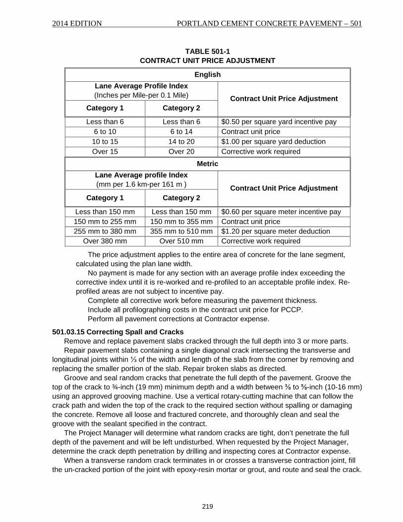
TABLE 501-1 CONTRACT UNIT PRICE ADJUSTMENT
English Lane Average Profile Index (Inches per Mile-per 0.1 Mile) Contract Unit Price Adjustment
Category 1 Category 2
Less than 6 Less than 6 $0.50 per square yard incentive pay 6 to 10 6 to 14 Contract unit price
10 to 15 14 to 20 $1.00 per square yard deduction Over 15 Over 20 Corrective work required
Metric Lane Average profile Index (mm per 1.6 km-per 161 m ) Contract Unit Price Adjustment
Category 1 Category 2
Less than 150 mm Less than 150 mm $0.60 per square meter incentive pay 150 mm to 255 mm 150 mm to 355 mm Contract unit price 255 mm to 380 mm 355 mm to 510 mm $1.20 per square meter deduction
Over 380 mm Over 510 mm Corrective work required
The price adjustment applies to the entire area of concrete for the lane segment, calculated using the plan lane width.
No payment is made for any section with an average profile index exceeding the corrective index until it is re-worked and re-profiled to an acceptable profile index. Re-profiled areas are not subject to incentive pay.
Complete all corrective work before measuring the pavement thickness. Include all profilographing costs in the contract unit price for PCCP. Perform all pavement corrections at Contractor expense.
501.03.15 Correcting Spall and Cracks Remove and replace pavement slabs cracked through the full depth into 3 or more parts. Repair pavement slabs containing a single diagonal crack intersecting the transverse and
longitudinal joints within ⅓ of the width and length of the slab from the corner by removing and replacing the smaller portion of the slab. Repair broken slabs as directed.
Groove and seal random cracks that penetrate the full depth of the pavement. Groove the top of the crack to ¾-inch (19 mm) minimum depth and a width between ⅜ to ⅝-inch (10-16 mm) using an approved grooving machine. Use a vertical rotary-cutting machine that can follow the crack path and widen the top of the crack to the required section without spalling or damaging the concrete. Remove all loose and fractured concrete, and thoroughly clean and seal the groove with the sealant specified in the contract.
The Project Manager will determine what random cracks are tight, don’t penetrate the full depth of the pavement and will be left undisturbed. When requested by the Project Manager, determine the crack depth penetration by drilling and inspecting cores at Contractor expense.
When a transverse random crack terminates in or crosses a transverse contraction joint, fill the un-cracked portion of the joint with epoxy-resin mortar or grout, and route and seal the crack.
501 – PORTLAND CEMENT CONCRETE PAVEMENT 2014 EDITION
220
When a transverse random crack nearly parallels the planned contraction joint and is within 5 feet (1.5 m) from a contraction joint, route, seal, and fill the crack with epoxy-resin grout or mortar.
When a transverse random crack is more than 5 feet (1.5 m) from the nearest contraction joint in the pavement, seal both the joint and the crack. Thoroughly clean the joints before filling with epoxy-resin mortar or grout.
Repair spalls by making a saw cut at least 1-inch (25 mm) outside the spalled area and to a minimum depth of 2 inches (50 mm). When the spalled area abuts a joint, make a saw-cut 2 inches (50 mm) deep or 1⁄6 the slab thickness, whichever is greater. Chip out the concrete between the saw cut and the joint or primary crack to solid concrete. Thoroughly clean the resulting cavity of all loose material. Apply a prime coat of epoxy-resin binder to the dry, cleaned surface of all cavity sides, except the working joint faces to be retained. Apply the prime coat by scrubbing it into the surface with a stiff bristle brush. Place hydraulic cement concrete or epoxy-resin concrete or mortar immediately following the prime coat application.
For spalled areas abutting working joints or working cracks penetrating full depth, place an insert or other bond breaker to maintain the joint or crack during the patch repair.
501.03.16 Opening to Traffic Do not permit traffic or Contractor equipment, excluding joint sawing and sealing equipment,
on the concrete until flex beam test results indicate the concrete has developed a minimum 350 psi (2,415 kPa) modulus of rupture.
Prepare the concrete flex beams in accordance with MT 101 and test for modulus of rupture using AASHTO T 97.
One test set consists of 3 beams. Take the concrete for the test beams from different concrete batches for each 2,500 square yards (2,100 m2) of concrete pavement and make at least 2 sets per day. Test the beam sets for modulus of rupture. Cure the test beams under the same environmental conditions as the pavement they represent. The pavement, represented by the beams, may be opened to traffic when the average modulus of rupture of the set exceeds 350 psi (2,415 kPa) and no individual beam’s modulus of rupture is less than 300 psi (2,070 kPa).
The Contractor may select the time for testing the beams. Test the flex beams on or near the project, using Contractor furnished equipment and with a Department Inspector witnessing the tests.
Include all costs to make, cure and test the flex beams in the contract unit price for PCCP. Opening to traffic does not constitute a final acceptance of the pavement. The pavement is
accepted upon confirmation of the 28-day flexural strength. Repair all concrete damaged prior to the final acceptance at Contractor expense.
501.03.17 Integral Curb Construct the curb monolithically with the pavement. Construct the inside face of the curb true to the lines and grades in the contract using the
finish specified for the concrete pavement, including longitudinal floating and burlap drag finishing.
Test the surface for longitudinal trueness with a straightedge while the concrete is still plastic. Meet the same surface requirements specified for the concrete pavement.
Continue concrete pavement joints through the integral curb at the same locations, of the same type, and constructed in the same manner.
Cure the integral curb as specified for concrete pavement.
2014 EDITION PORTLAND CEMENT CONCRETE PAVEMENT – 501
221
501.03.18 Weather and Night Limitations Place concrete at night only with the Project Manager’s written approval. Stop concrete work when the ambient temperature falls below 40 °F (4 °C) and do not
resume until the ambient air temperature reaches 35 °F (2 °C) and is rising. Do not place concrete on a frozen foundation course or subgrade. Remove and replace all concrete damaged by frost at Contractor expense.
501.03.19 Protection of Concrete Cover the concrete with an approved commercial insulating blanket, covering all pavement if
the ambient temperature falls below 35 °F (2 °C) during the cure period. Leave in place for 7 days.
The Project Manager may direct the leaving the blanketing in place beyond the 7-day curing period.
501.03.20 Pavement Thickness Construct concrete pavement to the specified thickness. Pavement not meeting the required
thickness will be subject to replacement in accordance with Subsection 501.03.20(B) or to the price adjustments according to Table 501-2. Tolerances allowed for subgrade or base course construction do not modify the thickness requirements.
A primary unit of pavement is the pavement area placed in each day’s paving operations. Within each primary unit there may be several secondary units as specified in 501.03.20(B)(2).
A. Thickness Verification. 1. Survey Method. Thickness measurement locations will be determined by random
sampling in accordance with MT 606. A minimum of 10 random locations will be tested for each 12,000 square feet (1,115 m2) of pavement placed within the primary unit. Elevations will be recorded to the nearest 0.01-foot (3 mm). Measurements will be taken as follows:
The locations will be selected on the finished surface before paving and at the same location on the finished concrete surface.
The thickness variation will be determined by subtracting the planned thickness from the constructed thickness at each surveyed location. Variations exceeding the planned thickness will be considered as a 0.00 feet (0.0 mm) deviation in the average. The average of the measurements will represent the variation for that primary unit.
2. Coring Method. The Project Manager reserves the right to verify the thickness or resolve discrepancies by coring using MT 106, recording that measurement to the nearest 0.01-foot (3 mm). Fill core holes with concrete of the same quality as used for the pavement at no cost to the Department.
B. Thickness Deficiency. 1. Variation less than or equal to 0.07-foot (21 mm). If the thickness variation in a
primary unit is less than 0.07-foot (21 mm), a deduction will be applied in the amount determined in Table 501-2 times the area of pavement in the primary unit. No incentive or contract adjustment will be allowed for constructed thicknesses exceeding the planned thickness.
501 – PORTLAND CEMENT CONCRETE PAVEMENT 2014 EDITION
222
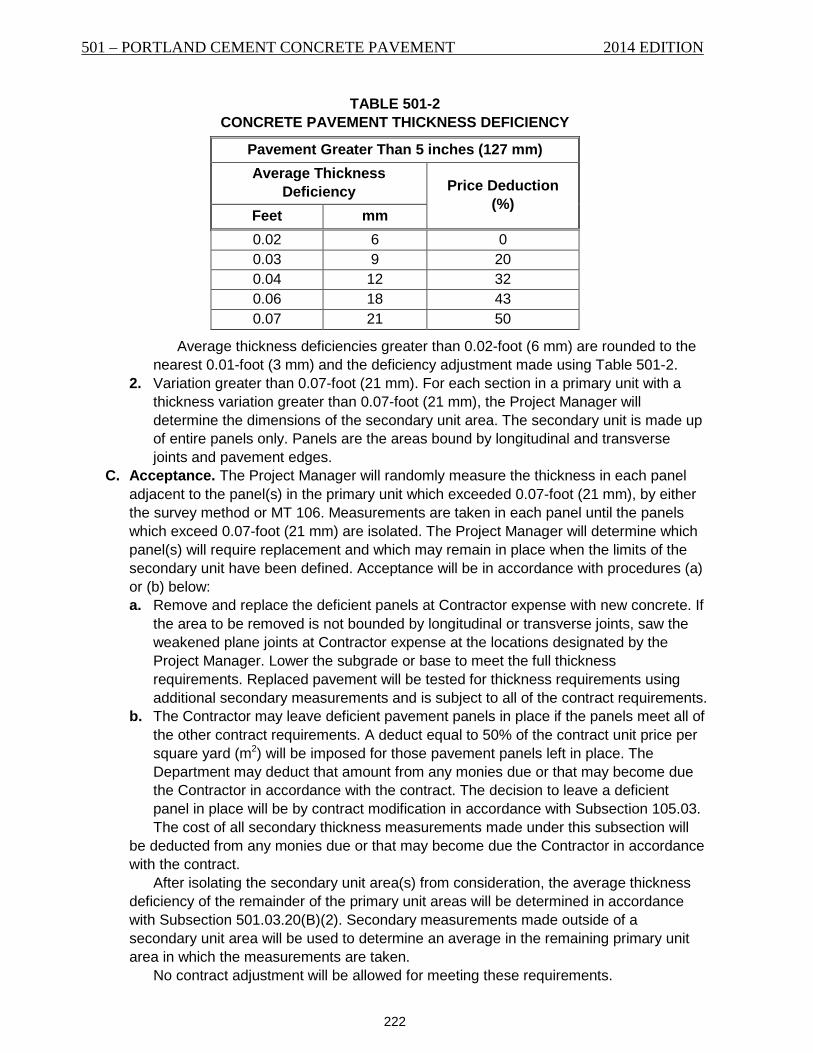
TABLE 501-2 CONCRETE PAVEMENT THICKNESS DEFICIENCY
Pavement Greater Than 5 inches (127 mm) Average Thickness
Deficiency Price Deduction (%)
Feet mm 0.02 6 0 0.03 9 20 0.04 12 32 0.06 18 43 0.07 21 50
Average thickness deficiencies greater than 0.02-foot (6 mm) are rounded to the nearest 0.01-foot (3 mm) and the deficiency adjustment made using Table 501-2.
2. Variation greater than 0.07-foot (21 mm). For each section in a primary unit with a thickness variation greater than 0.07-foot (21 mm), the Project Manager will determine the dimensions of the secondary unit area. The secondary unit is made up of entire panels only. Panels are the areas bound by longitudinal and transverse joints and pavement edges.
C. Acceptance. The Project Manager will randomly measure the thickness in each panel adjacent to the panel(s) in the primary unit which exceeded 0.07-foot (21 mm), by either the survey method or MT 106. Measurements are taken in each panel until the panels which exceed 0.07-foot (21 mm) are isolated. The Project Manager will determine which panel(s) will require replacement and which may remain in place when the limits of the secondary unit have been defined. Acceptance will be in accordance with procedures (a) or (b) below: a. Remove and replace the deficient panels at Contractor expense with new concrete. If
the area to be removed is not bounded by longitudinal or transverse joints, saw the weakened plane joints at Contractor expense at the locations designated by the Project Manager. Lower the subgrade or base to meet the full thickness requirements. Replaced pavement will be tested for thickness requirements using additional secondary measurements and is subject to all of the contract requirements.
b. The Contractor may leave deficient pavement panels in place if the panels meet all of the other contract requirements. A deduct equal to 50% of the contract unit price per square yard (m2) will be imposed for those pavement panels left in place. The Department may deduct that amount from any monies due or that may become due the Contractor in accordance with the contract. The decision to leave a deficient panel in place will be by contract modification in accordance with Subsection 105.03. The cost of all secondary thickness measurements made under this subsection will
be deducted from any monies due or that may become due the Contractor in accordance with the contract.
After isolating the secondary unit area(s) from consideration, the average thickness deficiency of the remainder of the primary unit areas will be determined in accordance with Subsection 501.03.20(B)(2). Secondary measurements made outside of a secondary unit area will be used to determine an average in the remaining primary unit area in which the measurements are taken.
No contract adjustment will be allowed for meeting these requirements.
2014 EDITION PORTLAND CEMENT CONCRETE PAVEMENT – 501
223
501.03.21 Accelerated Paving Techniques Submit a request with details for any proposed accelerated paving techniques to the Project
Manager a minimum of 7 calendar days before use. Accelerated paving techniques may include but are not limited to; admixtures, cement, alternative curing methods, sawing methods, and joint sealing.
501.04 METHOD OF MEASUREMENT Furnishing and installing all tie bars, dowels, setting and maintaining wire control lines,
sawing longitudinal and transverse joints, sealant, reinforcing steel, accelerated paving techniques, and testing for opening to traffic is not measured for payment. Include all costs in the unit price of PCCP.
501.04.1 Area Measurement PCCP is measured by the square yard (m2). The measured width is from outside to outside of completed pavement including integral
curb, not exceeding the specified width or the width ordered by the Project Manager. The length is measured along the centerline of the pavement surface. Fillets for widened sections or at drainage structures and similar locations placed monolithic
with the pavement are measured as pavement. Areas constructed other than as pavement are deducted from the pavement area. No
deduction is made for any fixture located within the pavement limits that has a surface area in the plane of the pavement surface of 1 square yard (0.80 m2) or less.
Integral curb included in the completed pavement is not measured separately for payment.
501.05 BASIS OF PAYMENT Payment for the completed and accepted quantities is made under the following:
Pay Item Pay Unit Cement Concrete Pavement Square Yard (m2)
Payment at the contract unit price is full compensation for resources necessary to complete the item of work in accordance with the contract.

501 – PORTLAND CEMENT CONCRETE PAVEMENT 2014 EDITION
224
225
SECTION 551 HYDRAULIC CEMENT CONCRETE
551.01 DESCRIPTION These are the general requirements for designing hydraulic cement concrete mixtures, the
ingredients, mixing, transporting, placing, curing, testing and acceptance for all classes and uses of hydraulic cement concrete.
551.02 MATERIALS Provide cementitious materials and admixtures from sources listed on the QPL.
551.02.1 Cement Furnish low-alkali hydraulic cements meeting the following requirements as specified in the
contract: A. Furnish low-alkali portland cement in accordance with AASHTO M 85, Type I, II, III, or V. B. Furnish low-alkali hydraulic blended cement in accordance with AASHTO M 240, Type IP
or IS. When fly ash or ground granulated blast furnace slag (GGBFS) is used in blended cement, limit the replacement amount to the maximums specified in Subsections 551.02.2 and 551.02.3 respectively.
C. Furnish low-alkali hydraulic cement in accordance with ASTM C1157, Type GU, HE, MS, HS, MH, or LH.
D. Meet the following requirements for all types of cement: 1. The total alkali content does not exceed 0.6%, calculated as the percentage of
sodium oxide (NaO) plus 0.658 times the percentage of potassium oxide (K2O). 2. Use only 1 brand of any 1 type of cement on the contract except by written approval
from the Project Manager. Different brands or grades, if approved, cannot be used alternately in any 1 pour.
3. Do not use air-entraining cements.
551.02.2 Fly Ash When included in the mix design, furnish fly ash in accordance AASHTO M 295, Class C or
F, including optional chemical requirements as set forth in Table 2.
551.02.3 Ground Granulated Blast Furnace Slag (GGBFS) When included in the mix design, furnish GGBFS in accordance with AASHTO M 302, Grade
100 or Grade 120.
551.02.4 Microsilica Fume (Silica Fume) When included in the mix design, furnish microsilica in accordance with AASHTO M 307.
551.02.5 Admixtures When included in the mix design, furnish admixtures in accordance with AASHTO M 194.
Ensure that the total contribution of chloride ions from all admixtures and air-entraining agents does not exceed 50 parts per million chloride ions (Cl-) by weight of cementitious material. All admixtures must be compatible with other constituents including cement, silica fume, GGBFS, fly ash, and other admixtures. Dose all chemical admixtures according to manufacturer’s recommendations unless trial batches provide adequate information for different dosage rates.
551.02.6 Air-entraining Agents Include an air-entraining agent in the mix design unless otherwise specified. Furnish an air-
entraining agent in accordance with AASHTO M 154.
551 – HYDRAULIC CEMENT CONCRETE 2014 EDITION
226
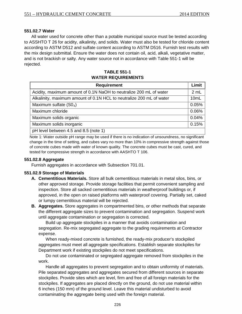
551.02.7 Water All water used for concrete other than a potable municipal source must be tested according
to ASSHTO T 26 for acidity, alkalinity, and solids. Water must also be tested for chloride content according to ASTM D512 and sulfate content according to ASTM D516. Furnish test results with the mix design submittal. Ensure the water does not contain oil, acid, alkali, vegetative matter, and is not brackish or salty. Any water source not in accordance with Table 551-1 will be rejected.
TABLE 551-1 WATER REQUIREMENTS
Requirement Limit Acidity, maximum amount of 0.1N NaOH to neutralize 200 mL of water 2 mL Alkalinity, maximum amount of 0.1N HCL to neutralize 200 mL of water 10mL Maximum sulfate (S04) 0.05% Maximum chloride 0.06% Maximum solids organic 0.04% Maximum solids inorganic 0.15% pH level between 4.5 and 8.5 (note 1)
Note 1: Water outside pH range may be used if there is no indication of unsoundness, no significant change in the time of setting, and cubes vary no more than 10% in compressive strength against those of concrete cubes made with water of known quality. The concrete cubes must be cast, cured, and tested for compressive strength in accordance with AASHTO T 106.
551.02.8 Aggregate Furnish aggregates in accordance with Subsection 701.01.
551.02.9 Storage of Materials A. Cementitious Materials. Store all bulk cementitious materials in metal silos, bins, or
other approved storage. Provide storage facilities that permit convenient sampling and inspection. Store all sacked cementitious materials in weatherproof buildings or, if approved, in the open on raised platforms with waterproof covering. Partially set, caked or lumpy cementitious material will be rejected.
B. Aggregates. Store aggregates in compartmented bins, or other methods that separate the different aggregate sizes to prevent contamination and segregation. Suspend work until aggregate contamination or segregation is corrected.
Build up aggregate stockpiles in a manner that avoids contamination and segregation. Re-mix segregated aggregate to the grading requirements at Contractor expense.
When ready-mixed concrete is furnished, the ready-mix producer’s stockpiled aggregates must meet all aggregate specifications. Establish separate stockpiles for Department work if existing stockpiles do not meet specifications.
Do not use contaminated or segregated aggregate removed from stockpiles in the work.
Handle all aggregates to prevent segregation and to obtain uniformity of materials. Pile separated aggregates and aggregates secured from different sources in separate stockpiles. Provide sites which are level, firm and free of all foreign materials for the stockpiles. If aggregates are placed directly on the ground, do not use material within 6 inches (150 mm) of the ground level. Leave this material undisturbed to avoid contaminating the aggregate being used with the foreign material.
2014 EDITION HYDRAULIC CEMENT CONCRETE – 551
227
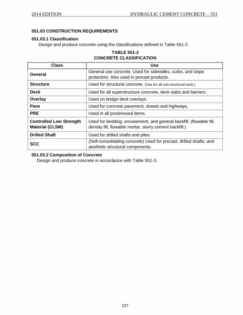
551.03 CONSTRUCTION REQUIREMENTS
551.03.1 Classification Design and produce concrete using the classifications defined in Table 551-2.
TABLE 551-2 CONCRETE CLASSIFICATION
Class Use
General General use concrete. Used for sidewalks, curbs, and slope protectors. Also used in precast products.
Structure Used for structural concrete. (Use for all sub-structural work.)
Deck Used for all superstructure concrete, deck slabs and barriers. Overlay Used on bridge deck overlays. Pave Used for concrete pavement, streets and highways. PRE Used in all prestressed items.
Controlled Low Strength Material (CLSM)
Used for bedding, encasement, and general backfill. (flowable fill, density fill, flowable mortar, slurry cement backfill.)
Drilled Shaft Used for drilled shafts and piles.
SCC (Self-consolidating concrete) Used for precast, drilled shafts, and aesthetic structural components.
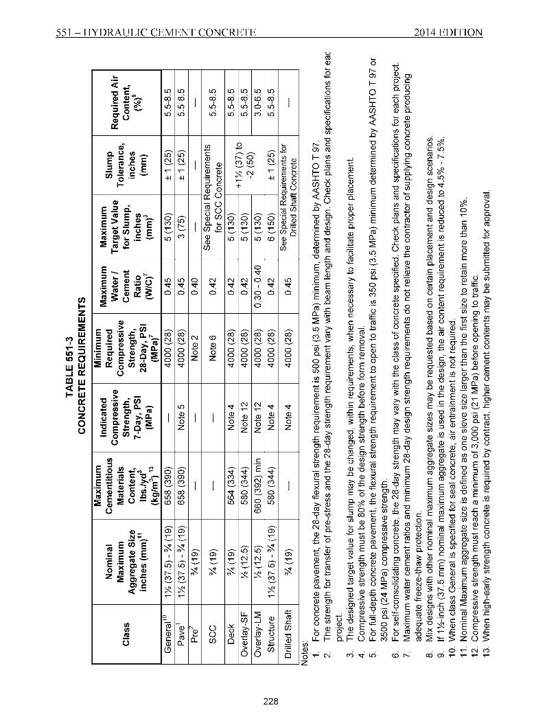
551.03.2 Composition of Concrete Design and produce concrete in accordance with Table 551-3.
2014 EDITION HYDRAULIC CEMENT CONCRETE – 551
229
Furnish the names of proposed suppliers and locations of proposed aggregate sources upon notice of award. Sources must be sampled, tested, and approved annually.
Coordinate with the Project Manager for submitting samples for testing. A. Design. Design the concrete mix as follows:
1. Submit a concrete mix design for each class of concrete to be used on a project. Meet all the requirements of MT 100.
2. Design the concrete mix to meet Table 551-3 requirements or the requirements stated below for specific classes of concrete. State the design proportions in terms of aggregates in a saturated, surface dry condition. Submit the proposed aggregate source and proportion computations. Submit a final mix design for approval at least 15 business days before intended use on form MTPCC-1.
3. Furnish materials meeting the requirements of Subsection 551.02. 4. Submit a new design when proposing any change in material sources. 5. The following supplementary cementitious materials (SCMs) may be used as partial
replacement for hydraulic cement in the mix design. a. Fly ash may be included in the mix design for up to 30% by weight of the total
cementitious material. Combinations of various classes of fly ash may not exceed 30% by weight of the total cementitious material.
b. Microsilica Fume may be included in the mix design for up to 10% by weight of the total cementitious material when a minimum of 15% fly ash or GGBFS is also included in the mix design or when the mix design incorporates acceptable blended cement.
c. Metakaolin may be included in the mix design for up to 20% by weight of the total cementitious material.
d. Ground granulated blast furnace slag may be included in the mix design for up to 50% by weight of the total cementitious material. When multiple SCMs are used in a design, the total replacement rate may not
exceed 50% by weight of the total cementitious material. Calculate the W/C ratio as the total weight of water divided by the total weight of
cementitious material. 6. Blended cements in accordance with Subsection 551.02 may be used in the mix
design. 7. When Type V cement is specified for sulfate resistance, other cementitious material
mixtures tested in accordance with ASTM C1012 may be submitted for approval. Acceptance will be based on expansion less than 0.10% at 18 months.
8. The mix design may include provisions that address special conditions of the project that would otherwise not be allowed. The following provisions may be included in the mix design: a. Delayed Initial Set. The mix may be designed for delayed set time to allow for
long haul or other project conditions. When delayed set is included in the mix design, the time requirements for placing the concrete in final position in accordance with Subsection 551.03.4 may be replaced by time to final placement requirements included in the mix design. Include in the mix design information on the delayed set provisions of the design and specific time to final placement requirements. Support the time to final placement with test results from trial batches.
b. Slow Strength Gain. The mix design may include cementitious materials or other admixtures that result in slow strength gain. When a slow strength gain is included in the mix design, include a recommendation for the age in days at which the
551 – HYDRAULIC CEMENT CONCRETE 2014 EDITION
230
strength will be obtained. The recommended age must be no less than 28 days and no more than 56 days. Support this recommendation with test results from trial batches. Upon acceptance, the recommended age will be used in all provisions that refer to 28-day strength.
B. Class Deck and Overlay-SF. Design and produce class Deck and Overlay-SF concrete in accordance with Table 551-3 and the following:
• Include silica fume and fly ash or GGBFS as SCMs in combination with compatible air entraining, water reducing and/or super-plasticizing admixtures. SCMs replacement quantities must meet the requirements of Subsection 551.02.
• Mix requires trial batch rapid chloride permeability test results in accordance with AASHTO T 277 less than 1500 coulombs at 28 days or surface resistivity test results in accordance with AASHTO TP 95 greater than 35 kilohm-centimeters at 28 days.
• Submit a batching sequence procedure with the mix design including the amount of material charged and the time before the next material will be added. Include approximate mixer revolutions for each stage of the sequence.
Alternative mix designs not in accordance with Table 551-3 may be accepted provided the following requirements are met: 1. Include in the design compressive strength test results according to AASHTO T 22 for
3, 7, and 28 days. The design must produce strengths in accordance with Table 551-3 by the specified age.
2. Include in the mix design shrinkage test results according to AASHTO T 160. The maximum allowed shrinkage for mix design acceptance is .0300% at 28 days.
3. Include in the mix design rapid chloride permeability (RCP) test results according to AASHTO T 277. The design must demonstrate a maximum of 1500 coulombs at 28 days. Alternatively, include in the mix design test results according to AASHTO TP 95, surface resistivity indication of concrete’s ability to resist chloride ion penetration. The design must demonstrate a minimum of 35 Kilohms-centimeters at 28 days.
4. Include in the mix design creep test results at 28 days according to ASTM C512. 5. Include in the mix design modulus of elasticity (MOE) results according to ASTM
C469. 6. Include in the mix design air-void spacing results according to ASTM C457 modified
point-count method at 100x magnification. The average of all tests must not exceed 0.009 inches (0.230 mm) with no single test greater than 0.010 inches (0.260 mm). The total air content must exceed 5.5%.
7. Design and produce concrete maintaining a plastic air content of 5.5% - 8.5%. 8. Submit a batching sequence procedure with the mix design including the amount of
material charged and the time before the next material will be added. Include approximate mixer revolutions for each stage of the sequence.
C. Class Drilled Shaft. Drilled shaft concrete is a highly workable concrete that can flow through dense reinforcement and adequately fill voids without segregation or excessive bleeding without the need for vibration. Drilled shaft concrete should not begin initial set until the placement is complete. Design and produce Class Drilled Shaft concrete in accordance with Table 551-3 and the following: 1. Set a target slump that meets the needs of the project. Set the target slump no lower
than 8 inches (200 mm). Do not place drilled shaft concrete having a slump of less than 7 inches (175 mm).
2. Include with the mix design an estimate of the maximum time from producing the 1st batch of concrete for a shaft to the anticipated completion of that shaft. All concrete
2014 EDITION HYDRAULIC CEMENT CONCRETE – 551
231
used for the drilled shaft must maintain a minimum of a 6-inch (150 mm) slump until 2 hours after the estimated completion.
3. Air entrainment may be used in drilled shaft concrete if needed to reduce bleed water or achieve certain placement properties
4. Self-consolidating concrete may be used for drilled shaft mix designs. When used, meet the above requirements and those of Subsection 551.03.2(F).
D. Latex-Modified Overlay Concrete (Overlay-LM). Design and produce overlay-LM concrete in accordance with the following requirements: 1. Use only Type I or Type II hydraulic cement. 2. Furnish concrete with a latex emulsion admixture rate of 25 gallons per cubic yard
(123.8 L/m3). Use a latex admixture containing a polymer of 66% ± 5% styrene and 34% ± 5% butadiene, with the polymer comprising between 46% and 49% of the total emulsion. The emulsion must have a sodium alkyl sulfate stabilizer acting as an anionic surfactant, polymer average particle size between 1,900 and 2,500 angstroms, a weight of 8.43 to 8.52 pounds per gallon (1.01 - 1.02 kg/L) at 75 °F (24 °C), and a pH between 9.5 and 11.0.
3. Protect the latex admixture from temperatures below 32 °F (0 °C) and above 85 °F (29 °C) at all times. Provide a thermometer capable of storing minimum and maximum temperatures and place it with any admixture stored on site. Replace admixture subjected to temperatures outside the range above at no expense to the Department.
E. Controlled Low Strength Material (CLSM). CLSM is a mixture of hydraulic cement, SCMs, aggregate, natural sands, silty sands, air entraining admixture and water. CLSM contains a low cementitious content for reduced strength development. Submit a mix design for approval including aggregate gradations, cement and SCM mill certifications, proportioning, and trial batch information. 1. Excavatable. Design and produce excavatable CLSM in accordance with the
following requirements: a. Unconfined compressive strength between 35 psi and 150 psi (0.24 - 1 MPa)
determined by ASTM D4832. b. Air content between 5% and 40% determined by ASTM D6023. c. Unit weight of 80 – 110 lbs/ft3 (1,280 – 1,760 kg/m3) determined by ASTM D6023. d. Consistent flow producing a self-leveling product free of segregation determined
by ASTM D6103 e. Do not use coarse aggregate in excavatable CLSM. (Maximum ⅜-inch (9.5 mm)
nominal maximum aggregate size designs.) 2. Non-Excavatable. Design and produce non-excavatable CLSM in accordance with
the following requirements: a. Unconfined compressive strength greater than 150 psi (1 MPa) determined by
ASTM D4832 b. Air content between 5% and 30% determined by ASTM D6023. c. Unit weight of 100-130 lbs/ft3 (1,600 – 2,080 kg/m3) determined by ASTM D6023. d. Consistent flow producing a self-leveling product free of segregation determined
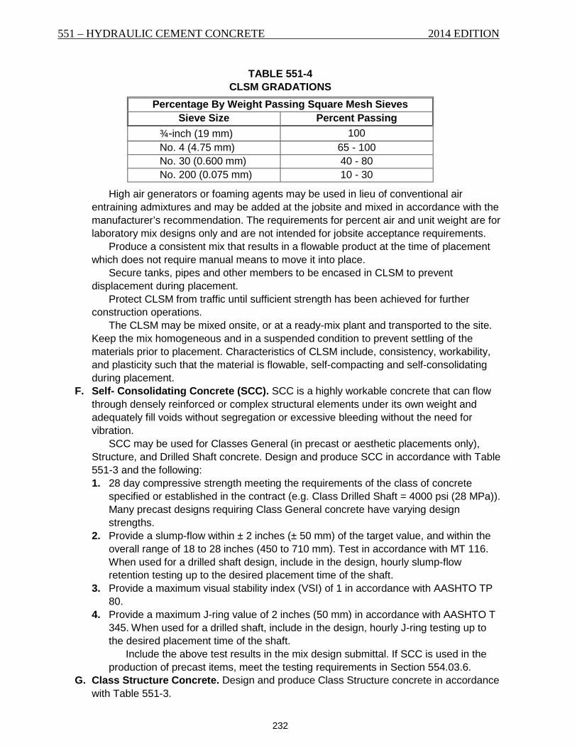
by ASTM D6103. Do not use materials in CLSM with a plasticity index over 4 according to MT 208. Furnish aggregates in accordance with Table 551-4.
551 – HYDRAULIC CEMENT CONCRETE 2014 EDITION
232
TABLE 551-4 CLSM GRADATIONS
Percentage By Weight Passing Square Mesh Sieves Sieve Size Percent Passing
¾-inch (19 mm) 100 No. 4 (4.75 mm) 65 - 100 No. 30 (0.600 mm) 40 - 80 No. 200 (0.075 mm) 10 - 30
High air generators or foaming agents may be used in lieu of conventional air entraining admixtures and may be added at the jobsite and mixed in accordance with the manufacturer’s recommendation. The requirements for percent air and unit weight are for laboratory mix designs only and are not intended for jobsite acceptance requirements.
Produce a consistent mix that results in a flowable product at the time of placement which does not require manual means to move it into place.
Secure tanks, pipes and other members to be encased in CLSM to prevent displacement during placement.
Protect CLSM from traffic until sufficient strength has been achieved for further construction operations.
The CLSM may be mixed onsite, or at a ready-mix plant and transported to the site. Keep the mix homogeneous and in a suspended condition to prevent settling of the materials prior to placement. Characteristics of CLSM include, consistency, workability, and plasticity such that the material is flowable, self-compacting and self-consolidating during placement.
F. Self- Consolidating Concrete (SCC). SCC is a highly workable concrete that can flow through densely reinforced or complex structural elements under its own weight and adequately fill voids without segregation or excessive bleeding without the need for vibration.
SCC may be used for Classes General (in precast or aesthetic placements only), Structure, and Drilled Shaft concrete. Design and produce SCC in accordance with Table 551-3 and the following: 1. 28 day compressive strength meeting the requirements of the class of concrete
specified or established in the contract (e.g. Class Drilled Shaft = 4000 psi (28 MPa)). Many precast designs requiring Class General concrete have varying design strengths.
2. Provide a slump-flow within ± 2 inches (± 50 mm) of the target value, and within the overall range of 18 to 28 inches (450 to 710 mm). Test in accordance with MT 116. When used for a drilled shaft design, include in the design, hourly slump-flow retention testing up to the desired placement time of the shaft.
3. Provide a maximum visual stability index (VSI) of 1 in accordance with AASHTO TP 80.
4. Provide a maximum J-ring value of 2 inches (50 mm) in accordance with AASHTO T 345. When used for a drilled shaft, include in the design, hourly J-ring testing up to the desired placement time of the shaft.
Include the above test results in the mix design submittal. If SCC is used in the production of precast items, meet the testing requirements in Section 554.03.6.
G. Class Structure Concrete. Design and produce Class Structure concrete in accordance with Table 551-3.
2014 EDITION HYDRAULIC CEMENT CONCRETE – 551
233
Alternative mix designs not in accordance with Table 551-3 may be accepted provided the following requirements are met. 1. Include in the design compressive strength test results according to AASHTO T 22 for
3, 7, and 28 days. The 28-day results must exceed specified strength. 2. Include in the mix design shrinkage test results according to AASHTO T 160. The
maximum allowed shrinkage for mix design acceptance is .0350% at 28 days. 3. Include in the mix design creep test results at 28 days according to ASTM C512. 4. Include in the mix design MOE results according to ASTM C469. 5. Include in the mix design air-void spacing results according to ASTM C457 modified
point-count method at 100x magnification. The average of all tests must not exceed 0.009-inch (230 μm) with no single test greater than 0.010-inch (260 μm). The total air content must exceed 5.5%.
6. Design and produce concrete maintaining a plastic air content of 5.5% - 8.5%. H. Class Pre Concrete. Design and produce Class Pre concrete in accordance with Table
551-3. Include the following in the mix design. 1. Include in the design compressive strength test results according to AASHTO T 22 for
3, 7, and 28 days. Also include strength tests at intended de-tensioning/release times (e.g. 12 hrs, 16 hrs, 24 hrs, etc.) The 28-day results must exceed specified strength.
2. Include in the mix design shrinkage test results according to AASHTO T 160. The maximum allowed shrinkage for mix design acceptance is .0350% at 28 days.
3. Include in the mix design creep test results at 28 days according to ASTM C512. 4. Include in the mix design MOE results according to ASTM C469.
I. Prepackaged Concrete. Prepackaged concrete or rapid set patching material must contain a product data sheet proving the product will meet the specifications required for its intended use. Prepackaged concrete is subject to Project Manager approval.
551.03.3 Batching, Mixing, Handling and Sampling Produce each class of specified concrete from approved material batched in the proportions
specified in the approved mix design. Correct for moisture content variations. All concrete aggregates are sampled using methods
described in MT 201 using sample sizes used in MT 202. MT 224 will be used to calculate combined gradations.
The water may be proportioned by weight or volume. Proportion the cement and aggregates by weight.
The temperature of the combined material must be less than 130 °F (54 °C) before the addition of cementitious materials.
Concrete batch plants and operations must meet the requirements of ASTM C94 prior to producing concrete for any work, including concrete for any field trial batches, and shall meet the requirements throughout the production of concrete including the following:
A. Quality Control. When requested, furnish documentation for all the plant’s equipment including each plants quality control procedures, calibration records, maintenance records, and any other information pertinent to proper concrete production. All measuring devices, batching equipment, trucks, and mixers are subject to approval.
B. Water. 1. Weigh Measurement. Ensure the weigh equipment measurements are not effected
by pressure variations in the water supply lines. The Project Manager may require an auxiliary tank for filling the weighing tank.
551 – HYDRAULIC CEMENT CONCRETE 2014 EDITION
234
2. Metering. Measure water volume by metering through a recording water-meter device, accurate to within plus or minus 1.0% of the required volume or plus or minus 1 gallon (3.8 L), whichever is less.
Completely discharge wash water from the mixer before starting any batching operation.
C. Cementitious Materials. 1. Proportion cementitious materials by weight on all projects for all classes of concrete. 2. Ensure equipment for weighing cementitious material is accurate to within 0.5% of the
true weight. 3. Weigh cementitious material to within 1.0% of the total cementitious material batch
weight. 4. Weigh each cementitious material separately.
D. Admixtures. If using 2 or more admixtures in a single concrete batch, add each admixture separately to prevent interaction of the different admixtures before mixing with other batch materials. Agitate admixtures to ensure homogeneous concentrations in accordance with the manufacturer’s recommendations.
If using a mechanical dispenser for proportioning admixtures, provide a site gauge or meter. Ensure unobstructed flow and accurate dosing of admixtures.
Batch admixtures in accordance with ASTM C94. E. Aggregate. Proportion aggregate by weight on all projects for all classes of concrete.
Ensure equipment for weighing aggregates is accurate to within 0.5% of the true weight.
Weigh aggregates to within 1.5% of the total aggregate batch weight. Weigh each size of aggregate separately.
F. Batch Ticket. Furnish the Project Manager a printed record of each batch in accordance with ASTM C94. Include on the ticket any water or admixture added after the record is printed and the initials of the person making the additions. Approval is required before any addition to the mix after batching and initial mixing has been completed.
G. Mixers. Use mixers that combine cementitious materials, aggregates, water, and admixtures within the specified time to form a uniformly mixed mass.
Meet the requirements of ASTM C94. Operate mixers following the manufacturer’s recommendations. The Department may require uniformity testing. When required, meet the
requirements of Subsection 106.04. Do not place concrete improperly or inadequately mixed in the work. If incorporated,
remove the concrete at no cost to the Department. Do not mix, transport, or place concrete using equipment with aluminum or aluminum
parts that contact the concrete. Produce concrete in such quantity and at such a rate as proper placement and
finishing will permit. Do not re-temper partially set concrete. Do not use mixed concrete that has remained in the truck mixer drum longer than 10
minutes without agitation. When silica fume is incorporated in the mix design, the maximum mixer revolutions
will be waived. Ensure a minimum of 50 revolutions at mixing speed when the concrete is in a low-slump stage [2 to 3 inches (50 to 75 mm)] to properly disperse silica fume particles.
H. Job-Site Additions. Do not make any additions to the plastic concrete without the approval of the Project Manager. On-site dosing of water or admixture in no way relieves the contractor of producing passing plastic and hardened concrete test results.
2014 EDITION HYDRAULIC CEMENT CONCRETE – 551
235
1. Water. Do not exceed the approved W/C ratio. The addition of water is allowed only 1 time and a minimum of 30 revolutions at
mixing speed are required before discharge of concrete. Do not add water if part of the batch has been discharged as a W/C ratio cannot be determined.
Do not add water if the slump is within specified range. 2. Admixture. Do not exceed manufacturer’s recommended dosage rates unless
otherwise approved in the mix design stage. Only admixtures included in the approved mix design may be dosed on-site. A
minimum of 30 revolutions at mixing speed are required before discharge of concrete. Do not add admixtures if any concrete has been discharged from the mixer other
than the minimal amount for initial testing. When the measured plastic air content or slump exceeds the upper test limit and
there is time available within the discharge time limit specified, rotate the load at agitation speed and re-test the air content and/or slump. Do not use additives to reduce the air content and/or slump.
No other materials may be added to the concrete mixture.
551.03.4 Transporting Concrete Ensure that the capacity of the plant and transportation equipment provides a delivery rate to
permit handling, placing, and finishing of the work. Time the delivery of loads to prevent the in-place concrete from taking initial set before
succeeding layers or lifts are placed. Do not permit any layer or lift of concrete to remain exposed in excess of 20 minutes before being covered by fresh concrete.
Document the method and time of delivery by batch tickets issued to the driver and signed by the Inspector at the plant if present. Deliver the ticket to the Inspector upon arriving at the project.
Place concrete with a temperature between 50 and 85 °F (10 and 29 °C). Meet the requirements of ASTM C94 and the following: A. Revolving Drum Mixers. Discharge the concrete at the job and place it in final position
within 1½ hours after introducing the mixing water and cement. If long hauls or other project conditions are expected, meet the requirements of Subsection 551.03.2(A)(7)(a).
When the ambient temperature is 85 °F (29 °C) or above, place the concrete in final position within 1 hour after the water and cement are introduced.
B. Non-agitating Transportation Equipment. Do not use non-agitating transport equipment to transport concrete except when placing concrete pavement in accordance with Section 501.
551.03.5 Placing Concrete Place concrete in accordance with Sections 501, 552, and 553. Always place concrete as near as possible to its final position. Do not place concrete that has taken initial set. Do not place concrete: 1. On frozen or ice-coated ground or subgrade; 2. Against or on ice-coated forms, reinforcing steel, structural steel, conduits, precast
members, or construction joints; 3. Under rainy conditions; stop the placement of concrete before the quantity of surface
water is sufficient to effect or damage surface mortar quality, cause a flow, or wash the concrete surface;
4. In any foundation until the Project Manager has approved its depth and character;
551 – HYDRAULIC CEMENT CONCRETE 2014 EDITION
236
5. In any form until the Project Manager has approved it and the placement of any reinforcing in it; or
6. In any work area when vibrations from nearby work may harm the concrete’s initial set or strength.
Ensure all reinforcement and other embedded items are clean and free from dried mortar, rust, scale, oil, or foreign matter before placing concrete.
Remove all sawdust, chips, other construction debris and extraneous matter from the interior of forms before placing concrete.
Treat the forms interior surfaces to prevent mortar adhesion. Moisten all foundations, forms, and contacting concrete surfaces with water just before the
concrete is placed. Remove any standing water on surfaces which will contact with the concrete. Provide a method of concrete placement that has a consistent, minimal impact on the
concrete properties. All equipment proposed for use in mixing, conveying, placing and compacting the concrete is subject to Project Manager approval prior to its use. All the necessary equipment for any particular pour must be on site and proven to be in working condition before the pour commences. Ensure the equipment is well maintained, suitable in kind and adequate in capacity for the work.
Support bars to maintain their position as shown in the contract. Place and secure all reinforcing, dowels, and other embedded items as specified. Deposit concrete in small quantities at many points and then work or run it along the forms.
Carefully fill each part of the forms, depositing the concrete as close as possible to its final position, working the coarse aggregates back from the face and forcing the concrete under and around the reinforcing bars.
Deposit concrete around steel shapes and closely spaced reinforcing bars, on 1 side of the steel, uniformly working it until the concrete flushes under the steel to the opposite side before any concrete is placed on the opposite side or over the steel.
Place concrete with means as to avoid segregation of the materials and the displacement of the reinforcement. Remove and discard any concrete that is segregated, is too wet for use, or is not of uniform consistency. Deposit concrete through an approved means when placement operations involve a free drop of concrete by more than 5 feet (1.5 m) to prevent segregation.
Place concrete in a continuous operation between expansion or construction joints. Thoroughly clean all chutes, troughs, and pipes after each run. Discharge any flushing water away from the forms and in place concrete. Once the concrete has taken initial set, avoid jarring the forms or straining the projecting
reinforcement ends. A. Placement Methods. All placement methods are subject to approval.
1. Truck Chute. Use metal or metal-lined troughs and chutes that extend to the point of deposit. Regulate the discharge.
2. Pumping Concrete. When concrete pumps are used for placement, prior to use on the first placement of each day, visually inspect the pumps water chamber for water leakage. Do not use a pump that allows free water to flow past the piston.
If a concrete pump is used as the placing system, discard the pump priming slurry before placement. Eliminating the priming slurry from the concrete may require that several cubic yards of concrete are discharged through the pumping system and discarded.
Use of a concrete pump requires a written plan to place the remaining concrete if the pump breaks down.
Provide a pump that produces a continuous flow of concrete without air pockets. Arrange equipment so that the impact on the plastic air content of the concrete is
2014 EDITION HYDRAULIC CEMENT CONCRETE – 551
237
affected as little as possible, and that the freshly placed concrete is not damaged by any form of vibration. If boom angles will vary significantly, furnish means to control air content variation.
3. Conveying Concrete. When a conveyor is used for placement, prior to use on the 1st placement of each day, visually inspect the conveyor to ensure proper operation. Provide a belt free of tears and holes and operates smooth and free of bouncing and jarring to prevent segregation of the concrete. Protect the concrete while on the conveyor to prevent the concrete’s plastic properties from changing.
Do not use a conveyor exceeding 200 feet (60 m). Equip all conveyors with a drop-chute and scraper to prevent segregation and
mortar loss respectively. Once concrete placement begins, ensure that there is proper and equal edge-
distance between the edge of the belt and windrow of concrete. 4. Bucketing Concrete. When a bucket is used for concrete placement, prior to use on
the first placement of each day, visually inspect the bucket for proper working condition and contaminants. The bucket should be clean and free of hardened concrete and excess of release agent.
Once concrete has been discharged into the bucket, do not place concrete back into a mixer to be altered or remixed.
B. Consolidation. Thoroughly consolidate concrete, except SCC, during and immediately after depositing into the work. Consolidate the concrete by mechanical vibration subject to the following: 1. Apply the vibration internally unless otherwise approved or as provided herein. 2. Vibrate the concrete at a minimum 4,500 impulses per minute or as recommended by
the vibrator manufacturer. 3. The vibration must visibly affect the concrete mass, producing a 1-inch (25 mm)
slump over a minimum 18-inch (455 mm) radius. 4. Use enough vibrators to consolidate each batch immediately after it’s placed. 5. Vibrate the concrete around the reinforcement and imbedded fixtures and into the
form corners and angles. 6. Vibrate at the point of deposit in areas of freshly deposited concrete. Slowly insert
and remove the vibrators from the concrete. Vibrate to thoroughly consolidate the concrete without causing segregation or forming localized grout areas.
7. Vibrate at uniformly spaced points and no farther apart than twice the radius over which the vibration is visible.
8. Do not apply vibration directly to or through the reinforcement or to non-plastic sections or layers of concrete. Do not use vibrators to transport concrete in the forms. Use plastic or rubber tipped vibrator heads when placing concrete near epoxy coated reinforcing steel.
9. Supplement vibration by spading and tamping to produce smooth surfaces and dense concrete along form surfaces, in corners and locations impractical to reach with the vibrators.
Refer to Section 501 for consolidation requirements for concrete paving.
551.03.6 Weather and Temperature Limitations Concreting during hot or cold weather requires an approved written plan to be implemented
upon abrupt changes in weather conditions or equipment failures. A. Hot Weather Concreting. Defined as job-site conditions that accelerate the rate of
moisture loss or rate of cement hydration of freshly mixed concrete. Do not place Classes
551 – HYDRAULIC CEMENT CONCRETE 2014 EDITION
238
Deck or Overlay concrete in temperatures exceeding 95 °F (35 °C). Other classes of concrete may be placed in temperatures exceeding 95 °F (35 °C) with Project Manager approval.
When hot weather concreting is anticipated, submit a hot weather concreting plan for review and approval. Include detailed procedures, including production, placement, finishing, curing and protection of concrete during hot weather concreting.
Do not place concrete when the ambient temperature is 85 °F (29 °C) and rising and/or the evaporation rate is greater than 0.2 lb/ft2/hr. (1 kg/m2/h) without an approved hot weather concreting plan. Do not place Classes Deck or Overlay without an approved plan when the ambient temperature is greater than 80 °F (27 °C) and/or when the evaporation rate is greater than 0.15 lb/ft2/hr. (0.75 kg/m2/h).
When hot weather as defined above exists, monitor site conditions (air temperature, humidity, wind speed) to assess the need for evaporation control measures beginning no later than 1 hour before the start of concrete placing operations. Continue to monitor site conditions at intervals of 30 minutes or less until specified curing procedures have been applied. 1. Materials. Produce concrete at a temperature such that its maximum temperature at
discharge will not exceed the specified maximum allowable concrete temperature. Acceptable production methods to reduce the temperature of the concrete include: shading aggregate stockpiles, sprinkling water on coarse aggregate stockpiles; using chilled water for concrete production; substituting chipped or shaved iced for portions of the mixing water; and cooling concrete materials using liquid nitrogen.
Include in the submittals for hot weather concreting which methods will be used and in what order they will be initiated when multiple methods are to be used. The substitution of other cooling methods will be considered by the Department when requested in the submittal and accompanied by satisfactory supporting data.
2. Construction. Include in the plan methods that will be used to maintain surfaces that will come in contact with the plastic concrete below 85 °F (29 °C). Include methods and equipment that will be used to keep the plastic concrete from cracking (e.g. fogging equipment, burlap, plastic, curing compounds, etc.). Describe devices or procedures that will be used to monitor wind speed, temperature, humidity, and other weather variables determining evaporation rate. Also include a detailed description of curing practices that will be used to supplement standard requirements in hot weather placements. Protect the concrete against thermal shrinkage cracking due to rapid drops in
concrete temperature greater than 40 °F (22 °C) during the first 48 hours unless otherwise specified.
Under hot weather conditions, scheduling placements at other-than-normal hours may be advisable. Concrete showing evidence of plastic shrinkage cracking or thermal cracking will be removed and replaced at no cost to the Department.
B. Cold Weather Concreting. Defined as when the weather forecast predicts air temperatures below 35 °F (2 °C) at any time during the specified curing and protection period following concrete placement. Assume all risk for placing concrete during cold weather. Replace frozen or damaged concrete at Contractor expense.
Remove ice, snow, and frost from the forms, subgrade, adjacent concrete, and reinforcing bars before placing concrete. Do not place concrete on frozen base or subgrade.
When cold weather concreting is anticipated, submit a cold weather concreting plan for review and approval. Include detailed procedures for production, transportation,
2014 EDITION HYDRAULIC CEMENT CONCRETE – 551
239
placement, curing, and temperature monitoring of the concrete during cold weather. Submit the plan a minimum of 15 calendar days prior to any concrete which is scheduled to be placed during cold weather. Prepare and submit a separate cold weather concreting plan for each concrete component which requires different methods of protection from cold weather. Clearly indicate which concrete components are covered by each submittal. 1. Cold Weather Plan. Include, as a minimum, the following items in the cold weather
concreting plans: a. Materials, details, and locations for insulating blankets, enclosures, or other
methods to be used to protect concrete from cold weather. b. Method for verifying the minimum concrete compressive strength has been
reached to allow formwork and cold weather protection removal. Indicate whether cylinder testing or maturity method will be used.
c. Recording thermometer information and location. Provide product data including type, manufacturer, model number, and temperature range. Include proposed number and location of thermometers in the concrete.
d. Heating equipment and locations, if used. Provide product information on heating equipment and equipment placement.
2. Fresh Concrete Temperatures. Place fresh concrete with a temperature between 50 and 85 °F (15 and 32 °C).
Eliminate frozen lumps, ice, and snow before aggregates are used in production. The Contractor may warm stockpiled aggregates with dry heat or steam, but not
by applying flame directly or under sheet metal. If the aggregates are in bins, steam or water coils or other heating methods may be used if aggregate quality is not affected. Live steam heating is not permitted on or through aggregates in bins. If using dry heat, increase mixing times enough to permit the dry aggregates to absorb moisture.
Use equipment and methods that heat the materials evenly. Do not add chlorides, chemical admixtures, or other ingredients to the concrete to
prevent freezing. 3. Protection of Concrete. Enclose the structure in such a way that the concrete and
air within the enclosure can be kept above 60 °F (15 °C) for a period of 7 calendar days or the specified curing period after placing the concrete. Ensure that the relative humidity remains above 80% within the enclosure.
Before placing concrete, provide adequate preheat to raise the temperature of the formwork, reinforcing steel, adjacent concrete, and subgrade to at least 35 °F (2 °C).
Submit documentation for a temperature recording device for approval. The device must be capable of recording temperatures a minimum of once per hour, 24 hours a day, for the entire curing period. Furnish and place enough temperature probes within the concrete to ensure the temperature of the concrete is adequately monitored. Install a minimum of 3 temperature probes within each concrete element. Ensure that the temperature probes cannot be dislodged by the placement of concrete, vibration, or workers. Include at least 1 additional temperature probe to record ambient outside air temperature. Where heated enclosures are used, include a temperature recording device inside the heated enclosure. Temperature probe locations are subject to approval. Submit the temperature recording device data to the Project Manager daily.
4. End of Curing Period. The conclusion of the curing period is defined when field cured cylinders meet design strength, maturity meter readings are satisfactory, or the
551 – HYDRAULIC CEMENT CONCRETE 2014 EDITION
240
specified curing days are reached and all temperature recording data has been submitted. a. Field Cured Specimens. Mold a minimum of 6 field cured cylinders per lot. Cast
field-cured cylinders in accordance with MT 101. Place the cylinders at locations designated by the Project Manager and expose them to the same conditions as the concrete being placed until they are removed for testing.
Test field-cured cylinders within 24 hours after removal from cold weather protection according to AASHTO T 22, except that the moist cure period is omitted. Perform tests using a certified testing laboratory. Furnish the Project Manager certified copies of the test results.
Cast enough cylinders to guarantee the required strength has been met for protection removal.
The Department reserves the right to witness selected tests and testing procedures.
Two cylinders constitute a test with the test value being the average of the 2 compressive strengths. The average of all sets must meet the specified strength. Continue curing and protection until the tests indicate the specified compressive strength is reached.
b. Removing Protection. When the curing period has ended and the design strength is met, withdraw protection and heating in such a manner so as not to induce thermal shock stresses in the concrete.
Gradually reduce the temperature of the concrete at a rate not exceeding 15 °F (9 °C) per hour. Do not exceed a temperature differential of 40 °F (4 °C) between the core of the element and the surface of the element. In addition the temperature differential between the surface of the element and the ambient air shall not exceed 15 °F (9 °C). Ambient air temperature is defined as the temperature at mid-height of the element and 12 inches (305 mm) from the surface of the element.
All concrete must achieve a minimum of 4000 psi (28 MPa) before being exposed to freeze/thaw cycles.
The Contractor is solely responsible for protecting concrete from inclement weather during the entire curing period. Permission given by the Project Manager to place concrete during cold weather in no way ensures acceptance of the work by the Department. Should the concrete placed under such conditions prove unsatisfactory in any way, the Project Manager has the right to reject the work although the plan and the work were carried out with the Project Manager’s permission.
551.03.7 Curing Concrete Continuously water cure any class of concrete used for bridge deck construction for 14
calendar days as specified below. Continuously water cure class Overlay-SF for 7 calendar days as specified below. Continuously water cure class Overlay-LM for 72 hours as specified below, followed by a dry
cure. Begin the dry cure at the end of the 72-hour wet cure period by removing the burlap and the polyethylene. Allow the concrete to undergo 48 hours of dry cure. Keep the bridge closed to traffic an additional 48 hours if the air temperature falls below 50 °F (10 °C) during the cure. Allow no traffic on the overlay surface until the end of the dry cure and the transverse deck grooving has been completed.
Continuously cure all other concrete surfaces for 7 calendar days by either water curing or liquid membrane-forming curing compound as specified below. Design strength must be verified by field-cured cylinders in accordance with AASHTO T 22.
2014 EDITION HYDRAULIC CEMENT CONCRETE – 551
241
Do not place curing compounds on concrete that is still bleeding. Protect freshly placed concrete from freezing, high temperatures, large temperature
differentials, premature drying, excessive moisture, and moisture loss for the period of time necessary to develop the desired concrete properties.
Protect exposed concrete surfaces from premature drying by covering with canvas, plastic sheets with sealed joints, burlap, or other approved materials. Keep the concrete moist. Continually moisten uncovered surfaces by fogging. Do not allow water to drip, flow, or puddle on the concrete surface during fog misting, when placing the burlap, or at any time before the concrete has achieved final set.
The concrete surfaces against forms may be cured by leaving the forms in place for at least 7 calendar days.
Keep the concrete surfaces moist after removing forms until surface repair is completed and one of the final cure methods described below is used. Surface repair includes removal of irregularities and repair of all depressions, voids, and air holes.
After placement, cure concrete surfaces as follows: A. Water Cure. Keep all finished top surface concrete moist with a fine water mist until the
burlap is placed. Place wet burlap in accordance with Subsection 717.01.2 immediately behind
concreting operations no later than 15 minutes after finishing. Do not use products having a laminated moisture barrier. Soak burlap for a minimum of 24 hours before use. Keep the burlap wet until concrete reaches sufficient strength to place soaker hoses or other effective means of providing moisture without marring the surface. Once a watering system is placed, place an approved reflective type sheeting or blanket over the watering system in accordance with Subsection 717.01.1 and cover to reduce evaporation. The entire concrete surface must remain moist throughout the full cure period. Ensure the temperature of all water used in the water cure is within 20 °F (11 °C) of the in-place concrete temperature. Secure covers and sheeting to prevent them from being lifted or displaced.
If an intermediate monomolecular film curing agent (evaporation retarder) is used, apply the monomolecular film in a light-fog application, using a pressure spray tank with an adjustable nozzle. Use a water-to-curing agent ratio and rate of application, both according to the manufacturer’s recommendations. Agitate the solution before each application.
Apply the monomolecular film immediately after the final finishing operation is completed on any area. Do not perform finishing after application of the curing agent.
Use of an evaporation retarder must be approved before use by the Project Manager. Furnish a product data sheet to the Project Manager before approval.
B. Liquid Membrane-Forming Curing Compound. Furnish and uniformly apply a liquid membrane-forming curing compound in accordance with Subsection 717.01.3 over exposed surfaces.
Deliver membrane-curing compound to the job in the manufacturer’s original container, clearly labeled with the manufacturer’s name and contents.
The compound must be ready to use as shipped by the manufacturer. Do not dilute the compound.
Do not use curing compound without providing the Project Manager a manufacturer’s product data sheet.
Use white-pigmented compound for pavements. Use a clear compound containing a fugitive dye on curbs, sidewalks, barrier rail,
substructure components, and superstructure components other than those requiring a
551 – HYDRAULIC CEMENT CONCRETE 2014 EDITION
242
water cure. The clear compound must contain a fugitive dye that makes the film visible on the concrete for at least 4 hours after application but does not affect the concrete surfaces natural color after curing.
Thoroughly mix and apply the compound following the manufacturer’s instructions or apply at a rate exceeding 1 gallon per 150 square feet (0.27 L/m2) and ensure complete coverage with no transparent areas showing obvious color differential.
Apply the curing compound immediately after the finishing operation using a mechanical pressure distribution system to provide uniform coverage. During windy conditions, equip the spray nozzles with hoods.
When concrete is placed in forms, immediately apply the curing compound after form removal if the concrete has not reached its design strength.
A hand-operated sprayer providing uniform coverage may be used to apply liquid curing compound to areas where a mechanical sprayer is impractical.
If the curing membrane is damaged from any cause during the curing period, re-coat the damaged areas immediately.
Do not apply membrane-curing compound to construction joint surfaces. Protect exposed steel during application of curing compounds.
C. Steam-Cure for Precast Concrete Items. Completely enclose or cover the casting beds for steam-cured members using curing blankets or other approved flexible coverings. Provide a minimum 6 inches (150 mm) of free air space between the enclosure or coverings and all concrete surfaces.
Secure flexible coverings to prevent moisture loss. Provide moisture before the cure cycle to aid hydration and prevent surface cracks caused by rapid water loss from the concrete.
Steam may be introduced before starting the cure cycle if the enclosure temperatures are maintained between 50 and 70 °F (10 and 21 °C). Fog-spray or cover the top surfaces of the members with wet blankets within 15 minutes after placing concrete to prevent moisture loss for a 3 hour period before the cure cycle.
Begin the steam-cure cycle after the concrete has been in place at least 3 hours. Maintain steam at 100% relative humidity, applied so it does not damage the surface of the concrete, forms, or tendons.
Raise the ambient temperature within the enclosures no faster than 40 °F (22 °C) per hour to a maximum temperature between 120 and 160 °F (49 and 71 °C). Maintain the temperature until the concrete has reached strength for transfer of prestress or design strength.
Once the cure cycle is complete, cool the precast items by decreasing the temperature within the enclosures no faster than 40 °F (22 °C) per hour until the temperature difference between the inside and outside air is within 25 °F (14 °C), unless otherwise approved.
Keep a curing time-temperature record for each concrete pour in the casting bed. Provide 1 automatic temperature-recording thermometer for each 200 feet (61 m), or fraction thereof, of continuous bed length used. Record curing temperatures continuously for the full curing cycle. Place the temperature sensors at approved locations. Supplement automatic recording thermometers with standard bulb-type thermometers placed at approved locations. Certify the accuracy of automatic recorders once each year or when the recorder accuracy is in question. Steam curing is not permitted without automatic recorders.
2014 EDITION HYDRAULIC CEMENT CONCRETE – 551
243
The sideforms may be removed at the Contractor’s discretion. Assume all responsibility removing forms before breaking the release cylinders. Concrete members damaged from early form removal will be rejected.
The cure cycle may be interrupted a maximum 20 minutes for form removal. Do not expose the members to below-freezing temperatures within 6 calendar days of
casting. In place of the 6-day requirement, the cure time may be based on the concrete strength. The concrete strength is determined by the average strengths of 3 standard 6 x 12-inch (152 x 305 mm) or 4 x 8-inch (102 x 203 mm) cylinders cast from different batches of concrete used in each casting. Expose these cylinders to the same cure and temperature conditions as the precast items. Immediately test the cylinders according to AASHTO T 22 without further curing, once they are removed from the cure area.
Curing may be discontinued if the average strengths of the 3 cylinders equals or exceeds specified strengths. Protect the member from freezing temperatures for the 6-day period if the average compressive strength fails to meet specified strength. Cool all members as specified in this Subsection.
Cast compression cylinders for field tests of the 28-day strengths following MT 101. Cast the number of test cylinders as required in Subsection 551.03.8(C) and MT 111.
The Contractor may submit in writing, alternate curing methods, for approval.
551.03.8 Testing and Acceptance of Concrete A. Sampling and Testing. Furnish an adequate and representative sample of concrete in
accordance with MT 105 from the point of placement to an area designated by the Project Manager for testing of concrete properties and molding of test specimens. The Department will take possession of the sample and begin the following applicable tests. 1. Compressive Strength Testing. Furnish samples for determining compressive
strength following MT 105. Test cylinders will be cast and cured following MT 101 and tested in accordance with AASHTO T 22 at a frequency determined by MT 601. Test cylinders for SCC will be cast and cured in accordance with MT 117. Compressive strength tests may be molded at any time if inconsistency between batches is identified or suspected. A compressive strength set consists of 4 test cylinders made at the same time from the same batch of concrete. Tests for plastic properties will also be run from the same sample used for compressive strength tests.
The Contractor may make additional cylinders to determine strength gain and to maintain job control. Make additional cylinders anytime strengths must be determined before 7 days for cure times, form removal, post-tensioning, or any other scenario requiring field-cured strength tests.
Standard compressive strength tests will be made at 7 and 28 days, except as specified below for concrete used in prestressed members.
The compressive strength results of the cylinders tested will determine if the concrete meets the required compressive strength in Table 551-3 or specified in the contract.
2. Testing of Plastic Concrete. Perform quality control sampling/testing during the concrete placement, including air content, temperature, and slump to maintain job control.
Furnish samples for determining slump, air, and temperature in accordance with MT 105. Slump will be tested in accordance with MT 104. Air content will be determined in accordance with MT 102. Temperature will be tested in accordance with ASTM C1064 at a frequency determined in accordance with MT 601. Plastic
551 – HYDRAULIC CEMENT CONCRETE 2014 EDITION
244
properties tests may be run at any time if inconsistency between batches is identified or suspected.
Slump flow and air content for SCC will be evaluated in accordance with MT 116 and MT 119.
Plastic concrete will also be subjected to a visual test for segregation. If segregation is identified by a “halo”, bleeding, aggregate agglomerations, or aggregate settlement (identified by a high sheen or bubbling) during the slump test, do not place the concrete. Take immediate steps to resolve the problem. Remove and replace any concrete placed showing signs of segregation at no expense to the department.
3. Flexural Strength Testing. In addition to the compressive strength requirements, Class Pave hydraulic cement concrete pavements require beam tests to determine the concretes flexural strength.
The number of flexural strength tests required for acceptance is determined by the Department on a random basis. The flexural strength results from 1 or a combination of the beams tested will be used to determine whether the concrete meets the required flexural strength specified in Table 551-3.
Flexural beams made in the field will be cast and cured in accordance with MT 101 and tested in accordance with AASHTO T 97.
4. Durability Testing. When applicable, furnish samples for determining permeability following MT 105. Test cylinders will be cast and cured following MT 101 and tested in accordance with AASHTO T 277 or AASHTO TP 95.
The Department may test hardened air content in accordance with ASTM C457 for acceptance.
5. Gradations. Samples for determining gradations of aggregates for concrete will be sampled in accordance with MT 201 and tested in accordance with MT 202. Combined gradations are determined in accordance with MT 215.
B. Acceptance of Concrete. The concrete must meet all contract specifications and the following: 1. Classes General, Deck, Pave, Structure, Overlay and Drilled Shaft Concrete.
These classes of concrete are evaluated for acceptance on a lot-by-lot basis. An individual lot is defined as a single days pour or every 200 yd3 (150 m3) of
concrete poured (i.e. 200 yd3 = 1 lot, 400 yd3 = 2 lots, etc.) whichever is less, excluding Class Pave. An individual lot of Class Pave concrete is defined as a single day’s pour or every 1,000 yd3 (750 m3) of concrete poured, whichever is less. Partial lots may be created or added to the preceding lot at the Project Manager’s discretion. Each lot is accepted or rejected based on the lot acceptance air tests, strength tests, gradation tests and when applicable, permeability tests. The pay factors for each lot accepted are determined from Table 551-5, 551-6, 551-7 and 551-8. a. Strength. A minimum of 2 standard compressive strength sets will be made for
each lot. Each set will be made from concrete taken from a separate batch or load randomly selected from all loads or batches in the lot. For a lot less than 30 cubic yards (23 m3), the Project Manager may elect to make 1 set of compressive strength cylinders to represent that lot.
Three cylinders from each set of cylinders are tested for compressive strength at 28 days and the fourth is tested at 7 days. The test result is the average of the strengths of the 3 individual 28 day cylinder specimens unless an outlier is identified. An outlier is defined here as 1 compressive strength specimen with a result differing from the average of the 2 closest compressive strength specimens
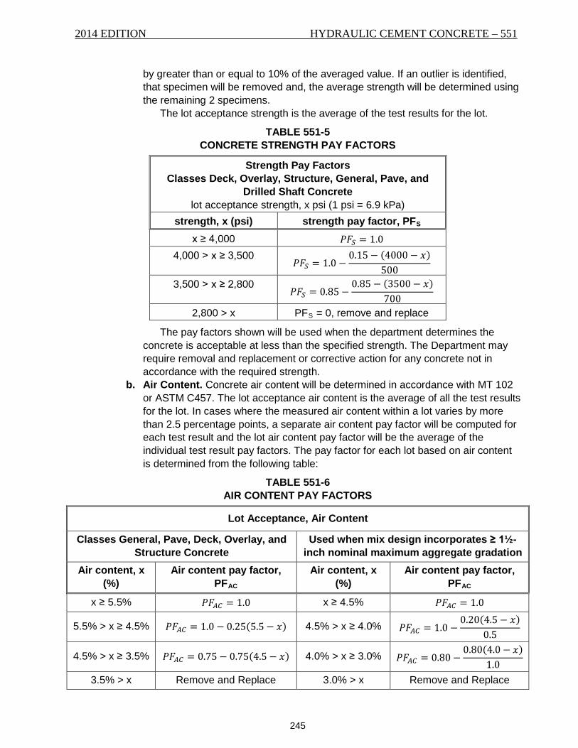
2014 EDITION HYDRAULIC CEMENT CONCRETE – 551
245
by greater than or equal to 10% of the averaged value. If an outlier is identified, that specimen will be removed and, the average strength will be determined using the remaining 2 specimens.
The lot acceptance strength is the average of the test results for the lot.
TABLE 551-5 CONCRETE STRENGTH PAY FACTORS
Strength Pay Factors Classes Deck, Overlay, Structure, General, Pave, and
Drilled Shaft Concrete lot acceptance strength, x psi (1 psi = 6.9 kPa)
strength, x (psi) strength pay factor, PFS
x ≥ 4,000 𝑃𝐹𝑆 = 1.0 4,000 > x ≥ 3,500
𝑃𝐹𝑆 = 1.0 −0.15− (4000 − 𝑥)
500
3,500 > x ≥ 2,800 𝑃𝐹𝑆 = 0.85−
0.85 − (3500− 𝑥)700
2,800 > x PFS = 0, remove and replace
The pay factors shown will be used when the department determines the concrete is acceptable at less than the specified strength. The Department may require removal and replacement or corrective action for any concrete not in accordance with the required strength.
b. Air Content. Concrete air content will be determined in accordance with MT 102 or ASTM C457. The lot acceptance air content is the average of all the test results for the lot. In cases where the measured air content within a lot varies by more than 2.5 percentage points, a separate air content pay factor will be computed for each test result and the lot air content pay factor will be the average of the individual test result pay factors. The pay factor for each lot based on air content is determined from the following table:
TABLE 551-6 AIR CONTENT PAY FACTORS
Lot Acceptance, Air Content
Classes General, Pave, Deck, Overlay, and Structure Concrete
Used when mix design incorporates ≥ 1½-inch nominal maximum aggregate gradation
Air content, x (%)
Air content pay factor, PFAC
Air content, x (%)
Air content pay factor, PFAC
x ≥ 5.5% 𝑃𝐹𝐴𝐶 = 1.0 x ≥ 4.5% 𝑃𝐹𝐴𝐶 = 1.0
5.5% > x ≥ 4.5% 𝑃𝐹𝐴𝐶 = 1.0 − 0.25(5.5− 𝑥) 4.5% > x ≥ 4.0% 𝑃𝐹𝐴𝐶 = 1.0 −0.20(4.5− 𝑥)
0.5
4.5% > x ≥ 3.5% 𝑃𝐹𝐴𝐶 = 0.75− 0.75(4.5− 𝑥) 4.0% > x ≥ 3.0% 𝑃𝐹𝐴𝐶 = 0.80−0.80(4.0− 𝑥)
1.0
3.5% > x Remove and Replace 3.0% > x Remove and Replace
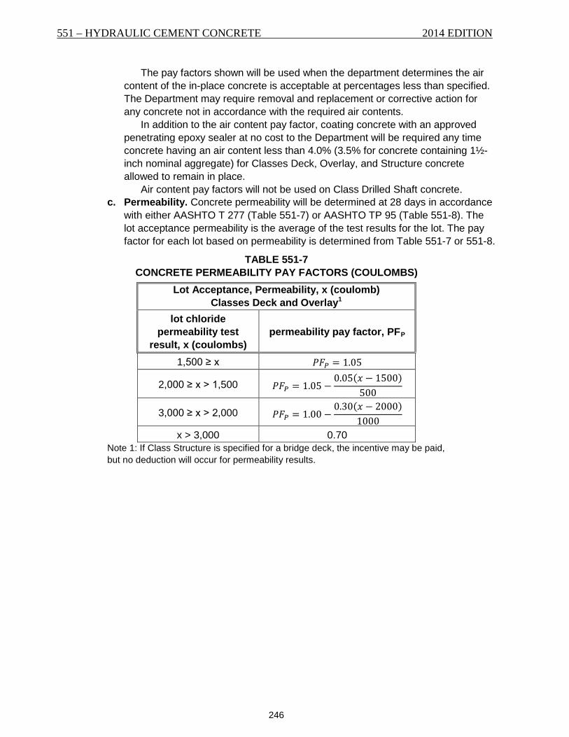
551 – HYDRAULIC CEMENT CONCRETE 2014 EDITION
246
The pay factors shown will be used when the department determines the air content of the in-place concrete is acceptable at percentages less than specified. The Department may require removal and replacement or corrective action for any concrete not in accordance with the required air contents.
In addition to the air content pay factor, coating concrete with an approved penetrating epoxy sealer at no cost to the Department will be required any time concrete having an air content less than 4.0% (3.5% for concrete containing 1½-inch nominal aggregate) for Classes Deck, Overlay, and Structure concrete allowed to remain in place.
Air content pay factors will not be used on Class Drilled Shaft concrete. c. Permeability. Concrete permeability will be determined at 28 days in accordance
with either AASHTO T 277 (Table 551-7) or AASHTO TP 95 (Table 551-8). The lot acceptance permeability is the average of the test results for the lot. The pay factor for each lot based on permeability is determined from Table 551-7 or 551-8.
TABLE 551-7 CONCRETE PERMEABILITY PAY FACTORS (COULOMBS)
Lot Acceptance, Permeability, x (coulomb) Classes Deck and Overlay1
lot chloride permeability test
result, x (coulombs) permeability pay factor, PFP
1,500 ≥ x 𝑃𝐹𝑃 = 1.05
2,000 ≥ x > 1,500 𝑃𝐹𝑃 = 1.05 −0.05(𝑥 − 1500)
500
3,000 ≥ x > 2,000 𝑃𝐹𝑃 = 1.00 −0.30(𝑥 − 2000)
1000
x > 3,000 0.70 Note 1: If Class Structure is specified for a bridge deck, the incentive may be paid, but no deduction will occur for permeability results.
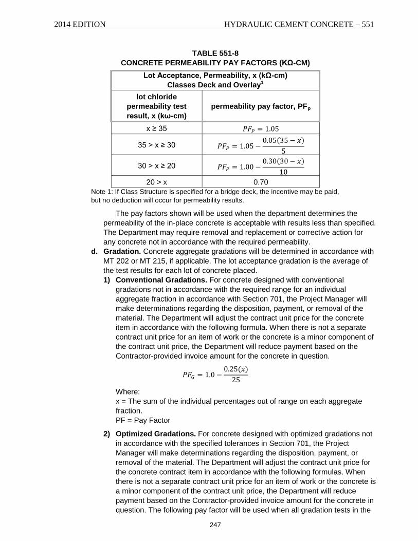
2014 EDITION HYDRAULIC CEMENT CONCRETE – 551
247
TABLE 551-8 CONCRETE PERMEABILITY PAY FACTORS (KΩ-CM)
Lot Acceptance, Permeability, x (kΩ-cm) Classes Deck and Overlay1
lot chloride permeability test result, x (kω-cm)
permeability pay factor, PFp
x ≥ 35 𝑃𝐹𝑃 = 1.05
35 > x ≥ 30 𝑃𝐹𝑃 = 1.05−0.05(35− 𝑥)
5
30 > x ≥ 20 𝑃𝐹𝑃 = 1.00−0.30(30− 𝑥)
10
20 > x 0.70 Note 1: If Class Structure is specified for a bridge deck, the incentive may be paid, but no deduction will occur for permeability results.
The pay factors shown will be used when the department determines the permeability of the in-place concrete is acceptable with results less than specified. The Department may require removal and replacement or corrective action for any concrete not in accordance with the required permeability.
d. Gradation. Concrete aggregate gradations will be determined in accordance with MT 202 or MT 215, if applicable. The lot acceptance gradation is the average of the test results for each lot of concrete placed. 1) Conventional Gradations. For concrete designed with conventional
gradations not in accordance with the required range for an individual aggregate fraction in accordance with Section 701, the Project Manager will make determinations regarding the disposition, payment, or removal of the material. The Department will adjust the contract unit price for the concrete item in accordance with the following formula. When there is not a separate contract unit price for an item of work or the concrete is a minor component of the contract unit price, the Department will reduce payment based on the Contractor-provided invoice amount for the concrete in question.
𝑃𝐹𝐺 = 1.0 −0.25(𝑥)
25
Where: x = The sum of the individual percentages out of range on each aggregate fraction. PF = Pay Factor
2) Optimized Gradations. For concrete designed with optimized gradations not in accordance with the specified tolerances in Section 701, the Project Manager will make determinations regarding the disposition, payment, or removal of the material. The Department will adjust the contract unit price for the concrete contract item in accordance with the following formulas. When there is not a separate contract unit price for an item of work or the concrete is a minor component of the contract unit price, the Department will reduce payment based on the Contractor-provided invoice amount for the concrete in question. The following pay factor will be used when all gradation tests in the
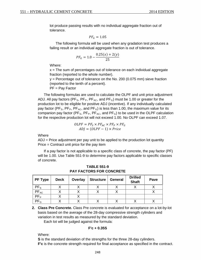
551 – HYDRAULIC CEMENT CONCRETE 2014 EDITION
248
lot produce passing results with no individual aggregate fraction out of tolerance.
𝑃𝐹𝐺 = 1.05
The following formula will be used when any gradation test produces a failing result or an individual aggregate fraction is out of tolerance.
𝑃𝐹𝐺 = 1.0−0.25(𝑥) + 2(𝑦)
25
Where: x = The sum of percentages out of tolerance on each individual aggregate fraction (reported to the whole number). y = Percentage out of tolerance on the No. 200 (0.075 mm) sieve fraction (reported to the tenth of a percent). PF = Pay Factor
The following formulas are used to calculate the OLPF and unit price adjustment ADJ. All pay factors (PFS, PFP, PFAC, and PFG) must be 1.00 or greater for the production lot to be eligible for positive ADJ (incentive). If any individually calculated pay factor (PFS, PFP, PFAC, and PFG) is less than 1.00, the maximum value for its companion pay factor (PFS, PFP, PFAC, and PFG) to be used in the OLPF calculation for the respective production lot will not exceed 1.00. No OLPF can exceed 1.07.
𝑂𝐿𝑃𝐹 = 𝑃𝐹𝑆 × 𝑃𝐹𝐴𝐶 × 𝑃𝐹𝑃 × 𝑃𝐹𝐺 𝐴𝐷𝐽 = (𝑂𝐿𝑃𝐹 − 1) × 𝑃𝑟𝑖𝑐𝑒
Where ADJ = Price adjustment per pay unit to be applied to the production lot quantity Price = Contract unit price for the pay item
If a pay factor is not applicable to a specific class of concrete, the pay factor (PF) will be 1.00. Use Table 551-9 to determine pay factors applicable to specific classes of concrete.
TABLE 551-9 PAY FACTORS FOR CONCRETE
PF Type Deck Overlay Structure General Drilled Shaft Pave
PFS X X X X X X PFAC X X X X X PFP X X PFG X X X X X X
2. Class Pre Concrete. Class Pre concrete is evaluated for acceptance on a lot-by-lot basis based on the average of the 28-day compressive strength cylinders and variation in test results as measured by the standard deviation.
Each lot will be judged against the formula:
F'c + 0.35S
Where: S is the standard deviation of the strengths for the three 28-day cylinders. F'c is the concrete strength required for final acceptance as specified in the contract.
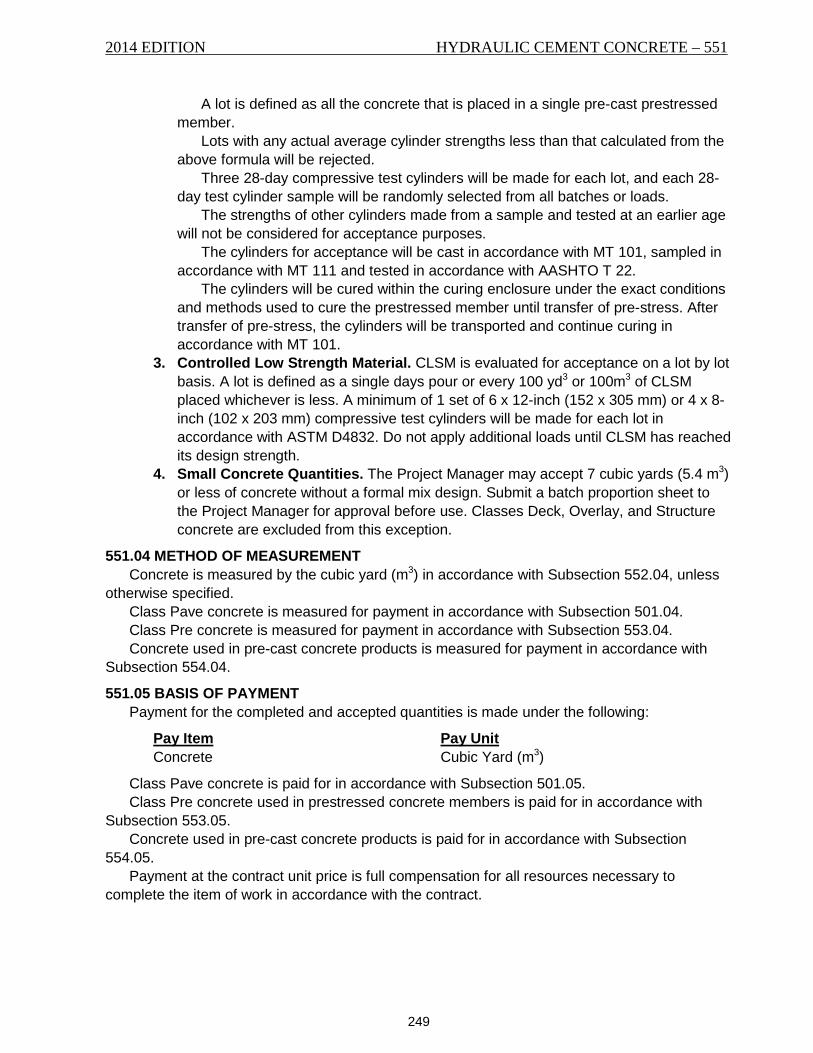
2014 EDITION HYDRAULIC CEMENT CONCRETE – 551
249
A lot is defined as all the concrete that is placed in a single pre-cast prestressed member.
Lots with any actual average cylinder strengths less than that calculated from the above formula will be rejected.
Three 28-day compressive test cylinders will be made for each lot, and each 28-day test cylinder sample will be randomly selected from all batches or loads.
The strengths of other cylinders made from a sample and tested at an earlier age will not be considered for acceptance purposes.
The cylinders for acceptance will be cast in accordance with MT 101, sampled in accordance with MT 111 and tested in accordance with AASHTO T 22.
The cylinders will be cured within the curing enclosure under the exact conditions and methods used to cure the prestressed member until transfer of pre-stress. After transfer of pre-stress, the cylinders will be transported and continue curing in accordance with MT 101.
3. Controlled Low Strength Material. CLSM is evaluated for acceptance on a lot by lot basis. A lot is defined as a single days pour or every 100 yd3 or 100m3 of CLSM placed whichever is less. A minimum of 1 set of 6 x 12-inch (152 x 305 mm) or 4 x 8-inch (102 x 203 mm) compressive test cylinders will be made for each lot in accordance with ASTM D4832. Do not apply additional loads until CLSM has reached its design strength.
4. Small Concrete Quantities. The Project Manager may accept 7 cubic yards (5.4 m3) or less of concrete without a formal mix design. Submit a batch proportion sheet to the Project Manager for approval before use. Classes Deck, Overlay, and Structure concrete are excluded from this exception.
551.04 METHOD OF MEASUREMENT Concrete is measured by the cubic yard (m3) in accordance with Subsection 552.04, unless
otherwise specified. Class Pave concrete is measured for payment in accordance with Subsection 501.04. Class Pre concrete is measured for payment in accordance with Subsection 553.04. Concrete used in pre-cast concrete products is measured for payment in accordance with
Subsection 554.04.
551.05 BASIS OF PAYMENT Payment for the completed and accepted quantities is made under the following:
Pay Item Pay Unit Concrete Cubic Yard (m3)
Class Pave concrete is paid for in accordance with Subsection 501.05. Class Pre concrete used in prestressed concrete members is paid for in accordance with
Subsection 553.05. Concrete used in pre-cast concrete products is paid for in accordance with Subsection
554.05. Payment at the contract unit price is full compensation for all resources necessary to
complete the item of work in accordance with the contract.

551 – HYDRAULIC CEMENT CONCRETE 2014 EDITION
250
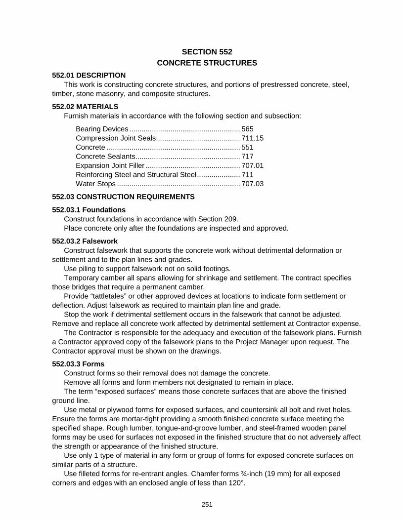
251
SECTION 552 CONCRETE STRUCTURES
552.01 DESCRIPTION This work is constructing concrete structures, and portions of prestressed concrete, steel,
timber, stone masonry, and composite structures.
552.02 MATERIALS Furnish materials in accordance with the following section and subsection:
Bearing Devices ...................................................... 565 Compression Joint Seals ......................................... 711.15 Concrete ................................................................. 551 Concrete Sealants ................................................... 717 Expansion Joint Filler .............................................. 707.01 Reinforcing Steel and Structural Steel ..................... 711 Water Stops ............................................................ 707.03
552.03 CONSTRUCTION REQUIREMENTS
552.03.1 Foundations Construct foundations in accordance with Section 209. Place concrete only after the foundations are inspected and approved.
552.03.2 Falsework Construct falsework that supports the concrete work without detrimental deformation or
settlement and to the plan lines and grades. Use piling to support falsework not on solid footings. Temporary camber all spans allowing for shrinkage and settlement. The contract specifies
those bridges that require a permanent camber. Provide “tattletales” or other approved devices at locations to indicate form settlement or
deflection. Adjust falsework as required to maintain plan line and grade. Stop the work if detrimental settlement occurs in the falsework that cannot be adjusted.
Remove and replace all concrete work affected by detrimental settlement at Contractor expense. The Contractor is responsible for the adequacy and execution of the falsework plans. Furnish
a Contractor approved copy of the falsework plans to the Project Manager upon request. The Contractor approval must be shown on the drawings.
552.03.3 Forms Construct forms so their removal does not damage the concrete. Remove all forms and form members not designated to remain in place. The term “exposed surfaces” means those concrete surfaces that are above the finished
ground line. Use metal or plywood forms for exposed surfaces, and countersink all bolt and rivet holes.
Ensure the forms are mortar-tight providing a smooth finished concrete surface meeting the specified shape. Rough lumber, tongue-and-groove lumber, and steel-framed wooden panel forms may be used for surfaces not exposed in the finished structure that do not adversely affect the strength or appearance of the finished structure.
Use only 1 type of material in any form or group of forms for exposed concrete surfaces on similar parts of a structure.
Use filleted forms for re-entrant angles. Chamfer forms ¾-inch (19 mm) for all exposed corners and edges with an enclosed angle of less than 120°.
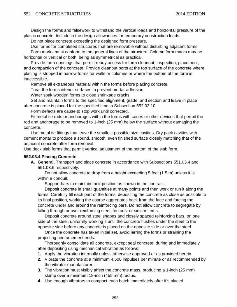
552 – CONCRETE STRUCTURES 2014 EDITION
252
Design the forms and falsework to withstand the vertical loads and horizontal pressure of the plastic concrete. Include in the design allowances for temporary construction loads.
Do not place concrete exceeding the designed form pressure. Use forms for completed structures that are removable without disturbing adjacent forms. Form marks must conform to the general lines of the structure. Column form marks may be
horizontal or vertical or both, being as symmetrical as practical. Provide form openings that permit ready access for form cleanout, inspection, placement,
and compaction of the concrete. Provide cleanout ports at the top surface of the concrete where placing is stopped in narrow forms for walls or columns or where the bottom of the form is inaccessible.
Remove all extraneous material within the forms before placing concrete. Treat the forms interior surfaces to prevent mortar adhesion. Water soak wooden forms to close shrinkage cracks. Set and maintain forms to the specified alignment, grade, and section and leave in place
after concrete is placed for the specified time in Subsection 552.03.10. Form defects are cause to stop work until corrected. Fit metal tie rods or anchorages within the forms with cones or other devices that permit the
rod and anchorage to be removed to 1-inch (25 mm) below the surface without damaging the concrete.
Use metal tie fittings that leave the smallest possible size cavities. Dry pack cavities with cement mortar to produce a sound, smooth, even finished surface closely matching that of the adjacent concrete after form removal. Use deck slab forms that permit vertical adjustment of the bottom of the slab form.
552.03.4 Placing Concrete A. General. Transport and place concrete in accordance with Subsections 551.03.4 and
551.03.5 respectively. Do not allow concrete to drop from a height exceeding 5 feet (1.5 m) unless it is
within a conduit. Support bars to maintain their position as shown in the contract. Deposit concrete in small quantities at many points and then work or run it along the
forms. Carefully fill each part of the forms, depositing the concrete as close as possible to its final position, working the coarse aggregates back from the face and forcing the concrete under and around the reinforcing bars. Do not allow concrete to segregate by falling through or over reinforcing steel, tie rods, or similar items.
Deposit concrete around steel shapes and closely spaced reinforcing bars, on one side of the steel, uniformly working it until the concrete flushes under the steel to the opposite side before any concrete is placed on the opposite side or over the steel.
Once the concrete has taken initial set, avoid jarring the forms or straining the projecting reinforcement ends.
Thoroughly consolidate all concrete, except seal concrete, during and immediately after depositing using mechanical vibration as follows: 1. Apply the vibration internally unless otherwise approved or as provided herein. 2. Vibrate the concrete at a minimum 4,500 impulses per minute or as recommended by
the vibrator manufacturer. 3. The vibration must visibly affect the concrete mass, producing a 1-inch (25 mm)
slump over a minimum 18-inch (455 mm) radius. 4. Use enough vibrators to compact each batch immediately after it’s placed.
2014 EDITION CONCRETE STRUCTURES – 552
253
5. Vibrate the concrete around the reinforcement and imbedded fixtures and into the form corners and angles.
Vibrate at the point of deposit in areas of freshly deposited concrete. Slowly insert and remove the vibrators from the concrete. Vibrate to thoroughly consolidate the concrete without causing segregation or forming localized grout areas.
Vibrate at uniformly spaced points and no farther apart than twice the radius over which the vibration is visible.
6. Do not apply vibration directly to or through the reinforcement or to non-plastic sections or layers of concrete. Do not use vibrators to transport concrete in the forms. Use plastic or rubber tipped vibrator heads when placing concrete near epoxy coated reinforcing steel.
7. Supplement vibration by spading and tamping to produce smooth surfaces and dense concrete along form surfaces, in corners and locations impractical to reach with the vibrators. These requirements apply to precast piling, concrete cribbing, and other precast
members unless the manufacturer’s vibration methods are approved. Place and secure all reinforcing, dowels, and other embedded items as specified.
Clean rust, scale, oil, dried mortar deposits or foreign material from all embedded materials before placing the concrete.
Continuously place concrete in each section of the work in horizontal layers, working continuously if necessary, to prevent stoppage planes.
Place the concrete in layers to thoroughly consolidate them with the concrete beneath. Place the succeeding layer before the previous layer has reached initial set.
Compact each layer to prevent separation planes between the preceding layer and the layer being placed.
The Project Manager may require an emergency bulkhead if concrete placement in a section is delayed longer than 20 minutes.
A construction joint is any place where concrete placement has stopped and the concrete has taken initial set. Make construction joints in accordance with Subsection 552.03.6.
Inset construction joints where a “feather edge” might be produced in the succeeding layer. Provide a minimum thickness of 6 inches (150 mm) in all succeeding layers.
Place concrete so all construction joints are across low shear stress regions and out of view to the greatest extent possible.
Place deck slab concrete a minimum of 7 calendar days after placing diaphragm concrete or when standard compressive strength test results verify that the diaphragm concrete has attained a compressive strength of 1,360 psi (9.5 MPa).
B. Pumping Concrete. Pump concrete in accordance with Subsection 551.03.5(A). C. Concrete Columns. Place concrete in one continuous operation, unless otherwise
specified. Allow columns to set at least 12 hours before placing the caps. Place concrete in the superstructure after the column forms have been stripped and
the column is inspected by the Project Manager. The superstructure load may be placed on the columns when the column concrete
reaches 80% of the required 28-day compressive strength, determined by testing standard 6 x 12-inch (152 x 305 mm) or 4 x 8-inch (102 x 203 mm) test cylinders.
D. Reserved. E. Concrete Slab and Girder Spans. Place slabs and girders having spans less than 30
feet (9.1 m) in one continuous operation.
552 – CONCRETE STRUCTURES 2014 EDITION
254
Concrete slabs with girders spanning 30 feet (9.1 m) or more may be placed in two operations, first placing the girder stems to the bottom of the slab haunches, and then placing the slab.
Use shear keys made of beveled timber blocks inserted at least 1½ inches (38 mm) in the fresh concrete at the top of each girder stem. Place the blocks to uniformly cover about ½ of the girder stem top surface. Remove the blocks when the concrete has set enough to retain its shape.
Do not place the slab until the girders have been in place for at least 24 hours. Check all falsework for shrinkage, settlement, and tighten all wedges to ensure
minimum deflection of the stems caused by the slab weight before placing the slab. Place concrete in girder haunches less than 3 feet (915 mm) high at the same time as
the girder stem. When any haunch or filler has a vertical height of 3 feet (915 mm) or more, place the
abutment or columns, the haunch, and the girder in 3 successive stages: • First, up to the lower side of the haunch. • Second, to the lower side of the girder. • Third, to completion.
F. Concrete Slip-forming. Concrete barrier rails on bridges may be slip-formed. Hand-finish the traffic face and top of the barrier to remove air holes and other
blemishes, followed by a light broomed finish. Sections with concrete slumps or bulges causing barrier rail misalignment or
inadequate concrete cover for reinforcing steel will be rejected.
552.03.5 Depositing Concrete Underwater Use Class General or Drilled Shaft concrete for seals specified in the contract. All costs for concrete placed outside of the plan dimensions and any change in the seal mix
design for the Contractor’s convenience is at Contractor expense. Do not place concrete underwater without Project Manager approval. When it is impractical or inadvisable to de-water an excavation before placing concrete,
place a seal course underwater to seal the cofferdam. Place the entire seal in one continuous operation, in accordance with the following:
• Use a tremie system; • Pump directly into a tremie hopper; or • Pump directly to the deposit point.
Use tremie systems made of rigid, watertight steel tube having a minimum diameter of 10 inches (255 mm) with a hopper at the top. Keep the tremie’s discharge end submerged in the deposited concrete, and the tremie tube full to the hopper bottom at all times during the concrete placement. When a load is dumped into the hopper, raise the tremie to start the flow of concrete until the load discharges to the hopper bottom. Use a tremie support that allows free movement of the discharge end and permits rapid lowering of the tremie to retard or stop the flow.
Pump seal concrete in accordance with Subsection 551.03.5(A). Have a backup concrete pump or tremie available at the site to ensure uninterrupted placing
of the entire foundation seal. Pump concrete into a tremie meeting the placing requirements for tremie-placed concrete. When concrete is pumped directly, the discharge tube must be a rigid pipe extending at least
5 feet (1.5 m) above the water level during placement. The discharge line from the top of the rigid pipe to the concrete pump may be flexible.
Prevent water from entering the tube while placing concrete. Fill the tubes without washing the concrete.
2014 EDITION CONCRETE STRUCTURES – 552
255
Place concrete in a consolidated mass without disturbing it once deposited. Do not place concrete in running water or expose it to the action of water before it has
reached final set. Keep water still at the point of deposit. Do not pump from the cofferdam while depositing concrete underwater. Make all formwork retaining concrete underwater practically watertight. Deposit concrete to produce horizontal surfaces. After the seal concrete has cured and can withstand the hydrostatic pressure, de-water the
cofferdam and place the remaining concrete in the dry. Prepare the top surface of the foundation seal in accordance with Subsection 552.03.6
before joining fresh concrete to the seal concrete. Remove high spots to provide the clearances for reinforcing steel or projection of embedded piling.
552.03.6 Construction Joints Obtain the Project Managers approval for construction joint locations. If the concrete develops initial set due to placement delays, the stopping point is considered
a construction joint. Place concrete continuously from joint to joint. Make the joints perpendicular to the principal
lines of stress and locate them at points of minimum shear. Place a gauge strip, at least 2 inches (50 mm) thick, at all horizontal construction joints and
at other directed locations inside the forms along all exposed faces to provide a straight line for the joints.
Before placing fresh concrete against set concrete, draw the forms tightly against the set concrete face and remove all gage strips and key forms. Remove all latence, loose and foreign materials from the surface by sandblasting, high-pressure water cutting, or light bushhammering. Keep the surface moist until resuming concrete placement. Apply a thin coat of neat cement to the surface or coat as specified just before resuming concrete placement.
Bond the successive courses by keying or doweling, as shown in the contract, at the top layer of each day’s work and at other points where work is interrupted.
552.03.7 Joints for Bridge Approach Slabs Construct and seal joints between concrete approach slabs and structures or concrete
pavement as specified. Use forms for joints that are removable without damaging the concrete. Protect the joint from damage and prevent debris and foreign material from entering the joint
before installing the seal. Limit construction equipment and other vehicles operated directly across the joint to rubber-
tired equipment, unless approved joint protection is used. Repair all spalls, fractures, breaks, or voids in the concrete joint surfaces as approved. Before placing the seal, clean the joints by abrasive blast or other similar methods, followed
with high-pressure air jets to remove all residue and foreign material. Protect expansion joint filler from the blast.
Make joint surfaces surface-dry when placing the seal.
552.03.8 Cold Weather Concreting Perform cold weather concreting in accordance with Subsection 551.03.6.
552.03.9 Curing Concrete Cure concrete in accordance with Subsections 551.03.6 and 551.03.7.
552.03.10 Removal of Forms and Falsework Do not release, loosen, or remove forms or falsework without the Project Manager’s
approval. This approval does not relieve the Contractor of responsibility for the safety of work.
552 – CONCRETE STRUCTURES 2014 EDITION
256
Remove all forms, blocks and bracing. Remove mortar lips and all irregularities caused by form joints.
The presence of honeycombed areas may cause rejection of the work, and upon written notice, require removal and rebuilding of the work in whole or part at Contractor expense.
After the forms are removed, cut back and repair all projecting wires, tie bolts, and other metal form ties passing through the concrete in accordance with Subsection 552.03.3.
Repair honeycombed concrete in all parts of the work and voids and depressions in exposed portions of the work as follows:
1. Chip back all coarse and broken material to a dense, uniform concrete surface with exposed solid coarse aggregate.
2. Cut back feather edges to form faces perpendicular to the surface being patched. 3. Saturate all cavity surfaces with water, and apply a thin layer of neat cement. 4. Fill the cavity with a thick mortar mixed in the same proportions as the concrete used in
the work and at the same temperature as the surface against which the mortar is placed. Use a blend of hydraulic cement, white hydraulic cement and sand, proportioned to match
the color of the concrete being repaired. Tamp the mortar into place, and float the surface using a wooden float before initial set takes place. Cure the patch in accordance with Subsection 551.03.7.
For patching large or deep areas, add coarse aggregate to the patching material to provide a dense, well-bonded, and cured patch.
Pull or remove all falsework piling 1-foot (305 mm) below the finished ground line or streambed unless otherwise specified.
552.03.11 Concrete Finish A. Broomed Finish. Finish the surface of concrete curbs and sidewalks to the lines and
grades in the contract. Work the concrete until the coarse aggregate is forced into the body of the concrete and no coarse aggregate is exposed. Float the surface with a wooden float producing a smooth and uniform surface.
Apply a broom finish to curbs or sidewalks. The texturing broom may be any medium-stiff bristled broom. Broom at right angles to the curb face or sidewalk and produce a uniform close spaced texture not exceeding ⅛-inch (3 mm) deep.
B. Bridge Decks. Finish deck slabs by the machine method, excluding small or irregularly shaped areas where a machine is impractical. 1. Machine Method. Use a self-propelled transverse finishing machine to strike off and
finish the surface of deck-slab concrete. Furnish the Project Manager information on the location and method of rail support, size of rail members, and a description of the machine.
Trial-run the finishing machine over the entire deck area to be finished before placing any concrete. Make the trial run with the machine and rails set to the specified grade and section. Attach a spacer to the bottom of the strike-off ⅛-inch (3 mm) in thickness less than the concrete cover shown in the contract. Adjust the support rails to compensate for dead-load deflections in the bridge girders. Adjust transverse strike-off support rails to match any changes in the deck section. Make transverse rail adjustments to maintain the specified surface tolerances. Record trial run transverse rail adjustments for use during the deck finishing operations. Make all adjustments to maintain proper grade, section, concrete cover over slab reinforcement, and slab thickness before any concrete is placed.
While placing the concrete, make enough strike-off passes to produce the required profile and section.
2014 EDITION CONCRETE STRUCTURES – 552
257
Maintain the heading of concrete placement nearly parallel to and not more than 10 feet (3 m) ahead of the strike-off. The concrete carried ahead of the strike-off must not cause wheel slippage or other unsatisfactory operation.
Orient the transverse axis of the finishing machine parallel to centerline of bearing on all pre-stress and steel girder spans skewed more than 15°. Make the concrete placement heading parallel to the strike-off heading to produce equal loads on each girder.
2. Hand Finishing. Obtain the Project Manager’s approval for hand finishing on deck slabs.
Strike off concrete using a template or vibrating screed and finish to a smooth, even surface meeting the required profile and section using longitudinal and transverse floating. Power trowels are not allowed.
3. Straight-edging. Test the plastic concrete surface for surface smoothness behind the finishing machine with a 10-foot (3 m) straightedge. Ensure the straightedge contacts the surface in successive positions parallel to the centerline of roadway across the entire slab width. Make longitudinal advances in maximum 5-foot (1.5 m) increments.
Immediately fill depressions with fresh concrete, consolidate, strike off, and finish. Remove high areas with a 10-foot (3 m) cutting straightedge and refinish. Correct all other surface defects using a 10-foot (3 m) float or combination float and cutting straightedge.
Provide footbridge(s) that clear span the fresh concrete for complete finishing, texturing, curing, straightedge testing, and surface correction.
Continue straightedge testing and surface correction until the entire surface meets the specified surface-smoothness requirements.
Limited hand floating may be used to correct defects left by the finishing machine. Hand floating is not required if the machine-finished surface meets surface-smoothness requirements and is free of defects.
4. Bridge Deck Surface Texture. Perform transverse deck grooving prior to allowing traffic on the new deck. After the Project Manager has approved the finished deck surface and concrete has cured for the specified cure period, saw cut transverse grooves into the finished deck. Use grooving equipment capable of saw cutting ⅛ ± 1⁄16-inch (3 ± 2 mm) wide and 3⁄16 ± 1⁄16-inch (5 ± 2 mm) deep at 1¼ ± 1⁄16-inch (30 ± 2 mm) center-to-center spacing. Do not overlap grooves during succeeding passes. Terminate grooves 1-foot (305 mm) from the face of rail or face of barriers and 4 inches (100 mm) from the paving notch, guard angles or expansion joints.
5. Broom Texture. Hand-finish the traffic surface of curbs, sidewalks, and other horizontal surfaces to receive a broom finish in accordance with Subsection 552.03.11(A).
6. Surface Smoothness. The finished surface must not vary more than 3⁄16-inch (5 mm) from a 10-foot (3 m) straightedge placed parallel to the roadway centerline.
High spots are measured as ½ the distance between the end of the straightedge and the pavement surface with the straightedge centered on the apex and the opposite end held in contact with the surface. Low spot variations are measured as the distance from the straightedge to the surface with the straightedge centered on the low point. Correct unacceptable surface variations by grinding off high spots and patching or filling low areas.
Subsequent surface sealing will not be required where the grooved surface is produced using a diamond-faced saw-type cutter for grinding.
552 – CONCRETE STRUCTURES 2014 EDITION
258
Perform surface sealing as follows for areas ground using conventional star-wheel-type cutters.
Seal all areas where removal exceeds ¼-inch (6 mm) in depth with an approved, concrete-colored, low-viscosity epoxy-resin adhesive. Produce a non-skid texture using a steel-tine broom or by applying medium-coarse silica sand to the plastic epoxy surface. Meet the surface smoothness requirements.
7. Protective, Remedial, and Corrective Work on Deck Slab Concrete. Do not place concrete for deck slabs and stop work when rain appears imminent. Take immediate action to strike off all concrete in place to promote drainage and prevent ponding.
Do not perform placing or finishing work that manipulates the concrete during precipitation.
Deck slabs areas where precipitation has been incorporated into the concrete may be rejected. Make a maximum 3 light passes with a straightedge float to remove excess water after the precipitation stops.
Protective work is that work necessary to protect unhardened concrete from damage by hail and rain. This includes covering the concrete with a protective covering when conditions warrant.
Remedial work is that work to restore a surface profile and texture on unhardened, rain-damaged concrete. Concrete damaged by rain to the extent the texture is obliterated and has a sandy appearance may be repaired by removing excess water and restoring it to the specified surface smoothness and texture.
Hardened concrete is concrete that is non-plastic and does not allow the vibrator to penetrate under its own weight.
Corrective work is work to provide an acceptable profile and texture on hardened, rain-damaged concrete.
Do not place fresh concrete against hardened concrete until a construction joint is placed in accordance with Subsection 552.03.6.
Correct areas exceeding the specified surface-smoothness tolerance and areas where the specified texture cannot be produced by grinding and grooving using concrete grinding machines.
Use a diamond saw type grooving machine. Grooves may be either longitudinal or transverse. Space grooves at ¾-inch
(19 mm) centers and be ⅛-inch (3 mm) wide by ⅛ to 3⁄16-inch deep (3 to 5 mm). Grooving is not required on areas that measure 10 feet (3.0 m) or less in length
parallel to centerline of roadway. Do not grind or groove so that concrete cover is reduced over the top reinforcing
bars to less than 2 inches (50 mm). Remove, replace, or overlay areas that cannot be corrected to the required
surface smoothness and texture by grinding and grooving. Submit proposed overlay methods in writing to the Project Manager for approval before use.
Remove all latence and hardened, excess concrete from construction joints before placing curbs, barriers, or other concrete.
Furnish all protective, remedial, and corrective work to provide an approved deck slab at Contractor expense.
C. Bridge Seats and Tops of Walls. Bring the concrete at bridge seats and tops of walls up to the required grade elevation, strike off with a straightedge, and float to a smooth, uniform texture.
Slope the concrete surfaces in areas of bridge bearing assemblies to drain water away from the bearing devices as specified.
2014 EDITION CONCRETE STRUCTURES – 552
259
Bushhammering is permitted only for leveling the concrete surface under the bearing plate and removing latence and loose and foreign material. Bushhammer to produce full, level bearing.
When necessary, place shims in accordance with Subsection 565.03.2. D. Ordinary Finish. An ordinary finish is the concrete surface left once the forms are
removed and all holes caused by form ties, trapped air, and all other defects are repaired. The finished surface must be true and even, free from stone pockets, depressions, or projections beyond the surface.
Ordinary finish is produced as follows: • Soak the concrete surface with water, and use the patching mortar specified in
Subsection 552.03.10, working it into the small air holes and other voids in the concrete face with a sponge float or wooden float.
• Rub off excess mortar after the mortar is partially set using burlap or carpet. • Remove uneven mortar surfaces that have set too hard by rubbing the entire
surface with a carborundum stone and water. • Produce a finished surface that is uniform in texture and color. Rub-finish all surfaces not repairable by the ordinary finish method in accordance with
Subsection 552.03.11(E). The ordinary finish may not be required for exposed vertical concrete surfaces listed
below, if the forming produces a true and uniform surface and minor defects are repaired as specified:
• Interior surfaces of box type concrete structures such as culverts, stockpasses, and minor grade separations; or
• Concrete diaphragms for prestress girders; or • Pier shafts, abutment walls, columns, struts, crossbeams, or other substructure
components located where they are not readily subject to public access or view. In general, substructure elements on bridges in undeveloped rural areas and more than 25 feet (7.6 m) from the edge of the public road, located in or over streams not used extensively for recreation, or exclusively over railway property are not considered subject to public access and view.
Good forming practice is considered as: • Using materials with a smooth surface free from holes, tears, dents, and gouges; • Using the largest practical pieces to minimize joints; • Arranging joints to be vertically or horizontally symmetrical; and • Using bracing to prevent bulges, offsets, and other major defects in the concrete
surface. Repair major surface defects, and finish the substructure unit surface or other
structural components to a uniform appearance. Major surface defects are large rock pockets, offsets at form joints exceeding ¼-inch
(6 mm), bulges, projections and depressions that deviate from the surface plane by more than ¼-inch (6 mm) in any 4-foot (1.2 m) length, and all other defects that reduce plan reinforcing bar cover by more than ¼-inch (6 mm).
Minor surface defects may be corrected without finishing the surrounding surface. Remove mortar fins even with the surrounding surface. Fill air holes exceeding ¾-inch (19 mm) in the longest dimension with mortar and strike off even with the surrounding surface. Patch minor rock pockets, tie holes, and the like as specified in Subsection 552.03.10.
552 – CONCRETE STRUCTURES 2014 EDITION
260
E. Rubbed Finish. After concrete has hardened, saturate the surface with water and rub using a medium-coarse carborundum stone with a small quantity of mortar on its face. Approved bonding agents may be used.
Use mortar consisting of cement and fine sand in the same proportions used in the concrete being rubbed.
When forms are removed while the concrete is “green”, wet the surface and rub it with a wooden float. If approved the thin mortar described above may be used for rubbing.
Continue rubbing until all form marks, projections, and irregularities are removed, all voids filled, and a uniform surface is obtained. Keep the paste produced by rubbing moist and allow it to set for at least 5 days. Smooth the surface by rubbing with a fine carborundum stone and water. Rub to produce a smooth texture and uniform color over the entire surface. After the final rubbing is complete and the surface has dried, rub the entire surface with burlap to remove loose mortar. The finished surface cannot have unsound patches, paste, powder, or objectionable marks.
F. Special Tooled Finish. Produce special tooled finishes using a bushhammer, a pick, a crandall, or other approved tool. Use air tools unless otherwise directed. Do not begin tooling until the concrete has set for at least 7 days, or longer if necessary, to prevent “picking” the aggregate out of the surface. Produce a finished surface showing broken aggregate in a matrix of mortar, each aggregate particle being in slight relief.
552.03.12 Installation of Expansion and Contraction Joints Construct expansion and contraction joints in accordance with the contract. A. Open Joints. Construct open joints by inserting and removing a template made of wood,
metal, or other approved material. Remove the template without chipping or breaking the concrete corners.
Do not extend reinforcement across an open joint unless specified. B. Filled Joints. Construct poured expansion joints similar to open joints. Use filler material
listed on the QPL and in accordance with Subsection 707.01. When pre-molded expansion joints are specified, the thickness of installed filler is
specified in the contract. Match the joint filler to the shape and size of the surfaces to be joined and fix it firmly against the existing surface. Do not displace the joint filler while placing concrete.
Where more than one piece of filler is used to cover any joint surface, place the abutting pieces in close contact and join them together with a layer of asphalt-saturated roofing felt. Use a minimum 20-pound (1 kg/m2) grade roofing felt having one side covered with hot asphalt.
The filled joints will be inspected immediately after the forms are removed. Neatly cut and remove all concrete or mortar that has sealed across the joint. Fill openings in deck slab joints during construction with an approved tar or asphalt as directed.
Place the necessary dowels, load-transfer devices, and other devices as specified. C. Steel Joints. Fabricate and paint the joints as specified. Ensure that the surface in the
finished plane is true and free of warping. Hold joints in the correct position during concrete placement. Use the openings at expansion joints shown in the contract, correcting for installation
temperature. Maintain the required clearance. D. Water Stops. Place water stops as specified.
552.03.13 Placing Anchor Bolts Install anchor bolts and dowel bars by one of the following methods:
• Securing in position prior to casting concrete;
2014 EDITION CONCRETE STRUCTURES – 552
261
• Drilling and grouting; or • Forming holes and grouting.
Determine the final bolt and dowel locations, making allowance for thermal effects on the superstructure at the time of grouting.
Ensure that all anchor bolts for shoe assemblies project above the plane of the substructure concrete to provide full anchor bolt and nut engagement after the final placement of the shoe assemblies.
Form holes by inserting treated wood plugs or metal pipe sleeves into the plastic concrete and withdrawing the devices after the concrete has partially set. Form holes at least 3 inches (75 mm) in diameter to allow for horizontal adjustment.
Drill holes at least 1-inch (25 mm) larger than the diameter of the anchor bolts. Verify diameter and depth before setting the beams.
Use an approved non-shrink or epoxy grout and fill holes ⅔ full. Force bolts and dowels down using uniform, even pressure or light blows with a hammer until the grout rises to the top of each hole and the bolts and dowels are inserted to the correct depth. Remove all excess grout, and clean the metal surfaces for painting. If below freezing temperatures are expected, a non-shrink or epoxy grout product formulated specifically for use at temperatures below freezing must be submitted for approval prior to grouting.
Protect holes against damage from ice by filling with a non-evaporating antifreeze solution. Before grouting, remove the antifreeze and thoroughly flush the holes with clean water.
Install the anchor bolt nuts as shown in the contract. Tighten the upper nut against the lower nut so neither nut can be turned by hand.
Correct all inaccuracies in bolt and dowel locations using approved methods at Contractor expense.
552.03.14 Setting Shoes and Bearing Plates Set shoes and bearing plates in accordance with Subsection 565.03.2.
552.03.15 Drainage Holes and Weep Holes Construct drainage holes and weep holes as specified. Place ports and vents for equalizing
hydrostatic pressure where required. Forms for weep holes through concrete may be wood, clay pipe, PVC pipe, concrete drain
pipe, wooden boxes, or metal. Remove wooden forms, if used, after the concrete is placed. Paint or galvanize exposed metal drain surfaces as specified.
552.03.16 Pipes, Conduits, and Ducts Install and rigidly brace pipes, conduits, and ducts encased in concrete before the concrete is
placed. Furnish and install 3-inch (75 mm) length plastic, PVC pipe or approved equal in the bottom
slab at the low point of each box girder cell to provide drainage for each cell. Extend the pipe ¼-inch (6 mm) below the bottom of the slab and flush with the slab’s top surface.
552.03.17 Loading of Piers and Abutments Do not place any superstructure load on finished bents, piers, or abutments until approved.
The minimum time before any superstructure load is placed on the substructure is 7 days, unless otherwise approved.
552.03.18 Silane Sealer Apply Silane sealer after the deck has been cast for at least 28 days and after transverse
deck grooving is completed.
552 – CONCRETE STRUCTURES 2014 EDITION
262
Remove any grease, oil or other contaminants on the deck surface by sandblasting the contaminated areas. Sandblast all area of the deck surface where vehicular traffic has been present.
Power wash the entire deck surface to remove concrete swarf, dirt, dust and other debris. Allow the deck to dry until it is visibly dry with no ponding or dark areas indicating moisture in the concrete surface.
Temporarily plug any deck drains and take any other precautions as necessary to ensure that the sealer is not allowed to drip off the deck.
Apply sealer in accordance with manufacturer’s recommendations until refusal. Refusal means that additional applications remain on the surface of the concrete and does not soak in. Provide the Project Manager with the manufacturer’s recommendations for application and storage.
552.03.19 Bridge Deck Crack Sealing A. Submittals. Submit 2 copies of the following to the Project Manager for review prior to
beginning work: 1. A MSDS for each shipment of the crack sealant components. 2. If high molecular weight methacrylate (HMWM) is supplied, provide certification from
an independent testing laboratory that the materials meet the contract requirements. 3. The dates of manufacture of the deck sealant materials, their lot numbers and date of
shelf-life expiration for each lot number. 4. A table showing the likely cure time in minutes for the allowable ambient temperature
range, in increments of 10 °F (6 °C). 5. A work plan for each structure that includes estimated times for surface preparation
and sealant application. B. Material Delivery and Storage. Store sufficient quantities of sealant materials at the site
to perform the entire application. Store these materials in their original containers and according to the manufacturer’s direction. These containers must bear the manufacturer’s label. The label must show the manufacture date, the batch number, the trade name brand, and quantity. Store containers of promoters and initiators in a manner that prevents leakage or spillage.
C. Surface Preparation. Clean all concrete surfaces for bridge deck crack sealant according to the manufacturer’s recommendations. Remove curing compound, laitance, grease, dirt, dust, salt, oil, asphalt, coating, and other foreign materials. Select the size of shot or sand, and travel speed of the equipment to provide a uniformly clean surface with a uniform profile. Sand blast areas that are not cleaned with the shot blast equipment. Remove striping to the maximum extent determined to be practical by the Project Manager using up to 3 passes with shot blasting, sandblasting or other approved equipment.
D. Application. Follow the manufacturer’s recommendations. The deck surface must appear dry to a visual inspection at the time of bridge deck crack sealant operations. The application rates may vary depending on field conditions. Pretreat visible cracks if required. Fill the cracks and keep them full. Continue the pretreating process until refusal of the crack to accept the material.
Apply the resin to the deck within 5 minutes of complete mixing. Redistribute excess material continuously, using squeegees or brooms, and stop before resin gels.
For HMWM applications, provide a manufacturer’s representative on site for the duration of the work, to provide expert assistance on storage, mixing, application, clean-
2014 EDITION CONCRETE STRUCTURES – 552
263
up and disposal of materials. The manufacturer’s representative is required to assist the Contractor in determining the application rates.
Broadcast sand mechanically over the entire treated area of the bridge deck to obtain a visually uniform coverage of 2.5 pounds per square yard (1.3 kg/m2). Spot sand as necessary to ensure complete coverage. Apply the sand prior to deck sealant cure to ensure adequate bonding. Remove excess sand as required.
E. Limitations. Do not use material after the shelf life date. Cover membrane and elastomeric material in deck joints, plug deck drain scuppers, seal cracks on underside of deck, and use other protective measures to protect waterways and bridge components. Replace or repair bridge components if materials or solvents harm their appearance or function, at no cost to the Department.
The following conditions govern work on each individual portion of a structure unless otherwise approved by the Project Manager in writing. 1. Do not apply deck sealant materials within 48 hours after a rain or when more than
10% probability of rain is forecast within 4 hours following the application. 2. Conduct the work in a continuous operation with the bridge deck crack sealant
application immediately following surface preparation. 3. Apply HMWM treatment only if the deck surface temperature and the air temperatures
are between 50 and 90 °F (10 and 32 °C) and the weather forecast shows air temperatures will remain within that range for at least 12 hours after the end of the application. Apply Epoxy treatment at temperature requirements in accordance with manufacturer recommendations. Do not permit traffic on the treated surface until the sand cover adheres sufficiently so
that no tracking will occur. F. New Bridge Slab Construction. Upon completion of the water cure and prior to
transverse grooving and Silane treatment, treat all visible cracks with crack sealer. In areas where crack sealer has puddled, spread sand on the surface in an amount to ensure adequate skid resistance. Visible cracks are cracks that can be seen unaided from about 4 feet (1.2 m) above the deck. The Project Manager will determine the locations where crack sealing is required.
552.03.20 Opening to Traffic Open concrete deck bridges to traffic only with the Project Manager’s approval. Do not open concrete bridge decks to traffic when the air temperature during the cure period
is 50 °F (10 °C) or higher, until one of the following is met: 1. Twenty-one days after placing concrete unless standard strength test results indicate
more time is required; or 2. Test results on field-cured test cylinders indicate that at least 90% of the required
minimum strength has been attained. Two cylinders constitute a test, with the test strength being the average of the strengths of the 2 individual cylinders.
The Project Manager will determine the opening date when the ambient temperature during the cure period has been lower than 50 °F (10 °C).
552.03.21 Acceptance Repair or replace all defective work at Contractor expense. Remove and replace the entire
section at Contractor expense when the Project Manager determines the repair is not adequate. Acceptance of the bridge deck concrete placement and water cure is based on meeting the
following requirements: 1. Proper use of fogging; 2. Proper water cure; and
552 – CONCRETE STRUCTURES 2014 EDITION
264
3. Application of silane sealer. The Project Manager will determine if these items meet this specification. The Project
Manager may apply a 10% deduct on each separate pour, for each item that does not meet specifications.
No incentive will be awarded for pay factors calculated from Subsection 551.03.8, if any deductions are applied. The Department may require corrective action for any concrete not in accordance with the contract at Contractor expense.
552.04 METHOD OF MEASUREMENT Concrete is measured in cubic yards (m3) from the plan dimensions. Plan quantities will not
be re-measured except as specified in Subsection 552.05. Fillets, scorings, and chamfers 2 inches (50 mm) or less in the greatest dimension are
omitted from the quantity calculations. No deductions are made for the concrete volume displaced by reinforcing steel, structural
steel, prestressed beams, anchor bolts, drains, weep holes, joint fillers, conduits, or junction boxes.
Deductions are made for the concrete volume displaced by steel and concrete piles. When ordered in writing by the Project Manager, concrete quantities placed outside neat
lines, are calculated and added for payment. No measurement is made for forms, falsework, cofferdams, bracing, and the like. Crack sealing is measured by the square yard (m2) of deck surface area treated. When
required as part of new bridge construction, crack sealing will be measured in accordance with Subsection 109.04.
Fogging, water cure and Silane sealer are not measured for payment. Transverse deck grooving is measured in square yards (m2) for the actual area grooved.
552.05 BASIS OF PAYMENT Payment for the completed and accepted quantities is made in accordance with the
following: A. The calculated quantities involved in changes ordered in writing by the Project Manager
are added or deducted from the contract quantities. B. A re-calculation will be made and the corrected quantity included for payment, in lieu of
the contract quantity, when the contract quantity of any complete structure element is in error by 2% or more. A complete structure element is the smallest portion of a total structure for which a quantity is included in the Estimated Plan Quantities Table shown in the contract. The party to the contract requesting an adjustment in quantity must present to the other party 3 copies of the description and location and recalculated quantities of the structure element that has the quantity error.
C. All Classes of concrete placed in bridges are subject to a payment reduction based on lot payment factors in accordance with Subsection 551.03.8(B)(1).
Partial payments for structure elements will be made based on the contract quantities as follows:
1. 40% of superstructure concrete when deck forms are complete in place. 2. 80% when all types of concrete are placed. 3. 85% when curing is complete. 4. 95% when all finishing is complete. 5. 100% when the structure element area is cleaned up to the Project Manager’s
satisfaction.
2014 EDITION CONCRETE STRUCTURES – 552
265
Pay Item Pay Unit Bridge Deck Crack Seal Square Yard (m2) Concrete Cubic Yard (m3) Transverse Deck Grooving Square Yard (m2)
Payment at the contract unit price is full compensation for all necessary resources to complete the item of work in accordance with the contract.

552 – CONCRETE STRUCTURES 2014 EDITION
266
267
SECTION 553 PRESTRESSED CONCRETE
MEMBERS 553.01 DESCRIPTION
This work is the furnishing and placing of precast, prestressed concrete beams, slabs, piling, and other structural members.
553.02 MATERIALS
553.02.1 Concrete Furnish concrete in accordance with Section 551.
553.02.2 Reinforcing Steel Furnish reinforcing steel in accordance with Subsection 711.01.1. Obtain the Project
Manager’s written approval for reinforcing steel substitutions. State on the fabrication drawings showing reinforcing steel details the following or similar
words: “All dimensions are out-to-out”.
553.02.3 Steel Rods and Bolts Furnish rods used as dowels and bolts in accordance with Subsection 711.07.
553.02.4 Prestress Steel Furnish high tensile strength steel wire in accordance with Subsection 711.11. Furnish the typical load-elongation curves for all shipments of prestress steel to the
fabrication plant. Ensure all prestress steel used in the work is free of rust, corrosion, dirt, oil, spatter from
welding or flame cutting, kinks, bends, nicks, broken wires, or other defects. Prestress steel is sampled in accordance with MT 111.
553.02.5 Enclosures Use metallic enclosures, excluding aluminum, or forms using removable cores or ducts made
of rubber or other approved material. Remove cores and ducts before installing the prestress steel.
Use enclosures that are mortar tight and maintain their shape when subjected to loading. Use enclosures that are ¼-inch (6 mm) larger in internal diameter than the bar, cable, strand,
or group of wires being enclosed. Equip cores or ducts with pipes or other connections for grout injection when pressure
grouting is specified.
553.02.6 Structural Steel Furnish structural steel in accordance with Subsection 711.02.
553.02.7 Elastomeric Bearing Devices Furnish elastomeric bearing devices in accordance with Subsection 711.14.
553.02.8 Fiber Reinforced Pads for Bearing Plates Furnish fiber reinforced pads in accordance with Subsection 711.16.
553.02.9 Deck Sealer Furnish deck sealer for precast prestressed deck sections which is listed on the QPL and in
accordance with Subsection 717.02.
553 – PRESTRESSED CONCRETE MEMBERS 2014 EDITION
268
553.02.10 Leveling Inserts Furnish Leveling inserts for precast prestressed deck sections designed for a minimum
working tension of 5,500 lbs. (24.4 kN) and have machine threaded ferrules. Use ¾-inch (19 mm) minimum diameter structural connection type leveling inserts.
553.03 CONSTRUCTION REQUIREMENTS
553.03.1 Fabrication Fabricate all prestressed concrete members using a manufacturing plant currently certified
by the Prestressed Concrete Institute or the National Precast Concrete Association in the category applicable to the member being fabricated. The Department will make an exemption for new manufacturing plants that are of the same ownership as an existing certified plant, provided the new manufacturing plant operates under the same quality assurance and control programs as the certified plants, modified to address any production differences, and all fabrication is performed under the direct supervision of a quality assurance and control manager provided by an existing pre-qualified plant. Direct supervision means that the quality assurance and control manager is on site during all fabrication performed in the new fabrication plant and is responsible for the quality assurance and control activities.
Furnish a copy of the plant’s current certification in the applicable category along with the fabrication drawings for the elements to be fabricated. For new manufacturing plants, submit and receive approval of any proposed modifications to the parent plant’s quality assurance and control program prior to beginning production. Allow 30 business days from the date submitted for Department review and approval.
The fabricator may prestress by pretension or post-tensioning the member, subject to the contract requirements.
Obtain written approval before changing the prestressing details.
553.03.2 Fabrication Drawings Before casting members, submit fabrication drawings and designs calculations to the Project
Manager. Show complete details of the method, materials, and equipment proposed for use in prestressing.
Include in the fabrication drawings the following information: 1. An erection layout of the members placed in the structure or structures with each
prestress member assigned a production number. Mark each completed member with an assigned number;
2. A tentative fabrication schedule; 3. The proposed mix design, including admixtures; 4. The prestress steel manufacturer’s name and the applicable specifications; 5. Details of the method and sequence of stressing including the numbered or lettered
layout to be followed to stress the member. Show complete details of the proposed method for tensioning the draped strands. Include in the details gauge and elongation readings for initial, intermediate, and final tensioning, as well as the deflection sequence, where applicable;
6. Complete details, including anticipated camber, tensioning forces (initial and final), and required concrete strengths (transfer and 28-day);
7. A complete detensioning procedure for the castings; 8. Details of items to be incorporated into the beam, such as chairs, inserts, hold-downs,
etc., listed by source, type, size or capacity, and supplier;
2014 EDITION PRESTRESSED CONCRETE MEMBERS – 553
269
9. Show all items incidental to the beams, such as bearing plates, rocker assemblies, anchor bolts, etc., if supplied by the beam fabricator. Include the specification and grade of all steel items;
10. All information and data required for fabrication; 11. Show the tack welding procedures; 12. Detail the use of all external weights or hold-downs if used. If weights are not required,
note it on the fabrication drawings; 13. Show the finish for all steel members incorporated in the beams. For galvanized items,
identify the applicable specification. For painted items specify paint type, manufacturer and recommended dried film thickness for each coat applied in the shop. Also identify surface preparation for each item to be painted. For paint requirements, refer to Section 612;
14. Submit welder certifications and welding procedure specifications for all welding done to any member incorporated into the beam. For welding requirements see Subsections 556.03.1 and 556.03.10; and
15. For precast prestressed deck sections: a) Show the location of the leveling inserts; and b) Drawings of the proposed leveling system.
Show all changes from the prestressed details in the contract. Submit 5 copies of shop drawings on 11ʺ x 17" or larger sheets and 5 copies of welding
procedures and design calculations on 8½" x 11" or larger sheets to the Project Manager. Shop drawings, design calculations, and welding procedures may be furnished in Adobe Acrobat Reader (.pdf) format in lieu of the hard copies. Ensure the submittal includes all information required to check the structural accuracy and fabrication procedures for the structure.
Structural shop drawings must be designed, and stamped by a professional engineer registered and licensed to conduct engineering in the State of Montana.
Do not begin fabrication until the Department approved drawings are received by both the plant and the Department Inspector. Coordinate the fabrication schedule with the Department Inspector.
553.03.3 Design of Concrete Mixtures The prestressed girder concrete must have a minimum ultimate compressive strength of
4,000 psi (27.6 MPa) at transfer of prestress and 5,000 psi (34.5 MPa) at 28 days. The actual required strengths are specified in the contract.
Furnish a concrete mix design that produces concrete meeting the specified compressive strengths before use. Approved changes to the mix design may be permitted during fabrication.
Use a concrete design of between 6.5 to 8.0 sacks of cement per cubic yard (350 - 450 kg/m3) of concrete.
Establish the Class Pre concrete slump range between 1 and 4½ inches (25 and 115 mm). The high and low limits of the range may not exceed 1½ inches (38 mm). The range may be changed with the Engineer’s approval.
553.03.4 Forms Use steel side and bottom forms. End bulkhead forms may be steel or plywood. Form joints and strand exits through bulkhead forms that are mortar tight. Check the grade and alignment of side forms before casting. Check the beam bed alignment
for displacement while placing the concrete. Construct beam bed forms to limit movement to not exceed ¼-inch (6 mm) from a straight
line in any 50-foot (15.25 m) length of the bed. Use clean forms that are free from warp, bulge, and other defects.
553 – PRESTRESSED CONCRETE MEMBERS 2014 EDITION
270
Do not exceed a maximum offset of 1⁄16-inch (2 mm) where form sections are joined. Treat the form facing with a bond breaker before each casting. Form treating materials that
stain or react with concrete are not permitted. Apply form oil or other bond breaker materials without contaminating the prestress strand and reinforcing steel. Clean soiled strand or reinforcing with a non-contaminating solvent.
Chamfer all exposed concrete edges, excluding the beam top, with an enclosed angle of less than 120°. Use chamfer strips having no irregularities, and maintain smooth joints with the chamfer tightly fitted against abutting forms.
Fit forms with a grade strip or other positive control to establish the nominal depth of the beam.
Use forms that can be removed from the member without damaging the concrete. Identify production form dimensions that vary from the contract beam dimensions on the
fabrication drawings.
553.03.5 Placing Reinforcing Steel Place and secure all reinforcing steel as shown in the contract before placing concrete. Fasten all bars at all intersections with adjacent bars. Do not tack weld reinforcing steel if the reinforcing bar is a stress-carrying member. Welding
non-stress reinforcing bars may be permitted with the Engineer’s approval. Reinforcing steel welds not shown on the approved tacking detail or fabrication drawings are prohibited.
For convenience, additional reinforcing steel may be tied in for securing inserts, void ducts, etc., or may be secured by tack welding.
Protect the tensioning strand from weld spatter using wet burlap or other protective covering. Replace all strands with weld spatter at Contractor expense.
Provide the distance between the reinforcing and side forms using approved stays, ties, or chairs. Do not use precast mortar blocks, pebbles, pieces of broken stone or brick, metal pipe, or wooden blocks.
Provide clearance between the beam stirrups and the beam bed using metal chair supports with stainless steel or other approved, corrosion-resistant legs.
Use reinforcing steel in the ends of prestressed beams to provide clearance for the paving notch block out, void ducts, embed plates and anchorages, and inserts without interfering with the reinforcement spacing.
Reinforcement in the prestressed member will be inspected in place and approved by the Inspector before the concrete is placed. Concrete placed before inspection may be rejected.
553.03.6 Prestressing Equipment Use approved jacking equipment for prestressing. Equip hydraulic jacks with pressure gauges. Have a certified testing laboratory calibrate each
jack and gauge combination as a unit with the cylinder extension in the approximate position that it will be in at the final jacking force. Have a certified calibration chart for each jack.
Other types of jacks may be used with proving rings or other approved devices calibrated by a qualified testing laboratory.
Calibrate jacking equipment once each year and after each repair. Re-calibration may be required if any jack or gauge gives erratic results or if the difference between the gauge reading and elongations exceed allowable limits.
Equip tensioning systems with hydraulic gauges that prevent the gauge pointer from fluctuating until the jacking load is released from the tendon. The gauge must read loads directly in pounds (Newtons) or have a chart to convert the dial reading into pounds (Newtons). Ensure the gauge readings are accurate to within ± 2%.
2014 EDITION PRESTRESSED CONCRETE MEMBERS – 553
271
Locate the gauges to provide the operator and Inspector a clear view of elongation measurements and gauge readings. Use gauge dials graduated in increments not exceeding 100 pounds (700 kPa) pressure. The gauge range or load cells must not use the lower 10% of the manufacturer’s rated capacity in determining the jacking stress, unless calibration data establishes accuracy within the 2% requirement at the lower range.
Ensure the end anchorages and prestressed member stressing blocks can maintain the required tension in all prestressed tendons until the concrete has been placed and reached transfer strength. Equip the end anchorages and stressing blocks to detect deflection while prestressing. The Inspector will check for deflection.
Provide the equipment to determine concrete compressive strengths at the location the prestressed members are manufactured. The test equipment may be mechanical or hydraulic, capable of applying and measuring the required load. Error for loads within the loading range of the test equipment may not exceed an error of ± 1.5%. Have a certified calibration diagram covering the entire use range with the equipment at all times. The indicated load of the testing equipment does not have to be corrected by calculation or by the calibration diagram to obtain values when the values are within the required variation of + 1.5%.
Certify the concrete strength testing equipment every 2 years; after each repair or adjustment of the equipment; when a non-portable machine has been moved; and whenever accuracy is in question.
553.03.7 Pretensioning Hold the prestressing elements in position using jacks when stressing. Keep a record of the
jacking force and the elongations. Multiple units may be cast in a continuous line and stressed at one time. Leave a space
between the ends of the units to permit cutting of the strands. Furnish strand in coils, reel-less packs, or on reels. Stringing may be performed by pulling
single or multiple strands. Pull to gradually relieve strand rotation on coil or reel-less packs. Strand with gripped points are not permitted within the lengths to be stressed. Bring all prestress tendons to the uniform initial tension on the approved fabrication
drawings. Initial tension is the minimum force required to equalize stresses and eliminate slack in the strand. Submit alternate initial loading proposals for approval.
The initial load may be applied by the jack used for single strand tensioning or by any other approved method that provides a definite, uniform load. Regardless of the method used, measure the initial load within ± 100 pounds (450 N). Compute elongation measurements for initial tensioning but do not use as a measurement of the initial force.
Once initial tensioning is complete, reference mark the strand as directed. The mark must provide an accurate measurement of elongation by final tensioning.
Measure the induced stress by gauge and check it by elongation, load cell, or both. The results must agree within 5%. Do not permit jacking stress to exceed 75% of the specified minimum ultimate tensile strength of the prestressing steel. Measure the strand elongation to within 1% of the theoretical elongation or ⅛-inch (3 mm), whichever is smaller. If a discrepancy between measured elongations and gauge readings exceeds 5%, check and correct the entire operation before proceeding with the work.
All uplift devices, hold-down devices, and strand openings in end bulkheads must have rounded, smooth surfaces at all contact points with the strand.
Take gauge readings, elongation measurements, and make calculations for elongation and include allowances for operational losses for the tensioning system used. These allowances must include losses for strand slippage, anchor movement, friction, strand rotation, and other forces acting on the strand.
553 – PRESTRESSED CONCRETE MEMBERS 2014 EDITION
272
If the temperature difference between the strand at the time of tensioning and the concrete at the time of pouring exceeds 30 °F (16 °C), correct the computed elongation measurements for the temperature differences.
Provide copies of the elongation calculations to fabrication and inspection personnel at the beginning of production to ensure all allowances for the method of tensioning have been considered.
553.03.8 Final Tensioning A. Single Strand Tensioning. After the initial load is applied and the reference marks are
established, individually pull the strands to the final load. Tension each strand to the load required by the gauge reading.
The elongation measurement must be within ± 5% of the load indicated by the gauge reading. If the load indicated by gauge reading doesn’t agree with the measured elongation within the required tolerance, discontinue tensioning and inspect the bed for restrictions that could affect the accuracy of the applied load.
If the measurements agree, three more strands may be tensioned. If elongation measurement and gauge readings are within the required tolerance, the remaining strands may be tensioned.
As some variation in the modulus of elasticity and the cross-sectional area of a strand does exist, the strand tensioning may be accepted, if the difference between the load determined by elongation and that indicated by the gauge does not exceed 5%. A maximum 10% of the total number of straight strands for any one line of casting will be accepted on this basis.
If the difference between the elongation load and gauge readings exceed the limits, discontinue tensioning and correct the problem.
B. Multiple Strand Tensioning. Mark each strand, once pre-loaded and seated in the anchorage, at both end anchorages to determine elongation and slippage. The Inspector will establish references to verify parallel movement.
Measure the stressing force by the gauge system and check it by the elongation measurement.
Use 2 load cells to verify the applied design load and check the uniformity of pull. Place one load cell on each side of the line of pull, preferably on the outermost strands of an upper row of straight strands.
If the hydraulic gauge and the load cells agree with the elongation measurements within ± 5%, the strands are acceptably tensioned. If the gauge reading is within 5% but either or both of the load cells exceed that limit, re-tension the strands including pre-loading. Locate and place the load cells on the strands nearest to those previously gauged.
If, upon re-tensioning, the load cells are within the 5% tolerance, no excess strand slippage has occurred, and the movable anchorage has traveled the required distance, the tensioning may be accepted.
If the difference between the gauge readings, load cell readings, and elongation measurements exceed the tolerance limit, stop tensioning and correct the problem.
Lubricate the jacking ram or rams, guide rods, and movable anchorage rails to minimize friction and run the ram through its length of travel at least four times before tensioning the strand.
C. Tensioning Draped Strands. Draped, pre-tensioned strands may be tensioned by partial jacking at the stressing block and subsequent depressing or uplifting to the deflected position or by tensioning to the initial and final loads with the tendons held in
2014 EDITION PRESTRESSED CONCRETE MEMBERS – 553
273
the final design position using pins, rollers, or other devices. Use low-friction devices at all points of slope change of the draped strand.
When draped strands are partially tensioned in the straight condition and then depressed to the final design position, determination of the final load is made as follows:
1. Before starting the tensioning operation, place a load cell at the dead end anchorage on one of the strands to be deflected in each line of beams.
2. The Inspector will select the strand to which the load cell will be placed. 3. Once tensioning is complete, the load cell reading must be within ± 6% of the final
design load. Should the load cell reading exceed the allowable tolerance, use additional deflecting
jacks to distribute friction and restraint at the deflection points or, if necessary, revise the entire method for applying the final design load within tolerances.
If the tensioning of draped strands indicates readings within the tolerances, the Inspector may require load cells for occasional checks.
If tensioning of the draped strands is performed by partial tensioning and uplift or, by tensioning in the draped position, submit the method for approval before use.
Strand splicing using approved devices is permitted. One splice is allowed on any one strand between anchorages. Splices must not fall within a beam. For single strand tensioning, the number of strands spliced is not restricted. When multiple strand tensioning is used, the number of strands spliced may not exceed 10% of the total number of strands in the casting line, or all the strands must be spliced.
Use only one manufacturer’s strand in any one tensioning operation. Use the same direction of twist of strand wires in all spliced strands. One wire failure in 7 wire strands may remain in the casting, subject to the following:
For beams with: a. Less than 20 strands ................................... No wire breaks permitted b. 20 to 39 strands ........................................... 1 wire break permitted c. 40 to 59 strands ........................................... 2 wire breaks permitted d. 60 or more strands ...................................... 3 wire breaks permitted Should wire breaks exceed these limits, or more than one wire break in any individual
strand, remove and replace that strand or strands. Locate all wire breaks allowed to remain in the casting, and securely wrap the broken
ends with tie wire to prevent unraveling. The Fabricator may be ordered to check the prestressing steel in a tensioned
member for loss of prestress before placing concrete. The Project Manager will approve the checking method for loss of prestress. Re-tension all strands showing a loss of prestress exceeding 3% of the original computed jacking stress.
Except as permitted in Subsection 553.03.5, do not weld, flame-cut, or ground welding equipment to the bed or forms after the prestress strand has been tensioned.
553.03.9 Placing Concrete A. General. Batch and mix concrete in accordance with Subsection 551.03.3, except as
provided below: 1. Provide master batch sheets to the Project Manager for review before production. 2. A timing device that locks the discharge gates of a stationary mixer is not required,
however, the mixer must not be emptied until the materials have been mixed the specified time.
3. Ready-mix delivery slips are not required unless specifically requested.
553 – PRESTRESSED CONCRETE MEMBERS 2014 EDITION
274
The batching operation and equipment may be inspected at any time. The work will be stopped for failure to use approved procedures or equipment.
B. Method and Manner. Place concrete in accordance with Subsection 552.03.4 and the following.
Obtain the Project Manager’s approval before placing concrete in large members. Concrete may be placed in the member in a single lift if satisfactory results are obtained, or in multiple horizontal lifts provided cold joints are not formed. Remove and replace concrete containing cold joints. When concrete is placed in layers, place the first lift to fill the form slightly above the juncture of the bottom flange and the beam web.
Compact the concrete immediately after pouring with high-frequency mechanical vibrators operating at a minimum 4,500 impulses per minute. Apply vibration internally, externally, or a combination of both methods to flush the mortar to the surface of the forms. Vibrate succeeding concrete layers to extend into the previously placed layer. Use vibrators to thoroughly consolidate the concrete to a plastic mass without causing segregation. Do not permit vibrator heads to contact reinforcing steel, prestressing steel, or other embedded items to aid consolidation. Slowly insert and remove internal vibrators from the concrete.
Have one additional vibrator available at the site at all times during concrete pours. C. Concreting in Adverse Weather Conditions. Perform concrete work in accordance with
Subsection 551.03.6 when the ambient air temperature falls below 40 °F (4 °C), except that the placement temperature for steam-cured Class Pre concrete must be between 50 and 90 °F (10 and 32 °C) at placement.
When the ambient temperature before concrete is placed is 35 °F (2 °C) or less, pre-heat forms to a minimum 50 °F (10 °C) removing all frost, snow, and ice from the forms and components to be embedded in the concrete.
Do not permit the concrete temperature to exceed 90 °F (32 °C). Cover open buckets of concrete with wet burlap mats or other approved coverings,
when necessary, to prevent slump loss or premature drying.
553.03.10 Curing Water-cure or steam-cure prestressed concrete members in accordance with Subsection
551.03.7.
553.03.11 Transfer of Prestress Prestressed strands may be released when the concrete has: 1. Reached the minimum compressive strength for transfer of prestress; 2. The cure cycle is complete; and 3. Restrictive forms are removed. If delays are anticipated, maintain the temperature in the curing enclosure at a minimum 50 °F (10 °C) until transfer of prestress. Use positive, external hold-downs or weights to offset the uplifting forces in the member
when the hold-down strands are released, when required. Use a method of harped and straight strands release to hold the lateral eccentricity of
prestress to a minimum. Detail the bed release and the strand-cutting pattern on the fabrication drawings. Changes to the release procedures shown on the approved drawings are not permitted except by written request and the Engineer’s written approval.
Cast cylinders to determine prestressed transfer strengths using MT 101 and MT 111 as modified below:
• Cast and cure the release cylinders under the exact conditions the prestressed members were cured.
2014 EDITION PRESTRESSED CONCRETE MEMBERS – 553
275
• The concrete sample for each cylinder will be selected at random from different batches.
Once the cure cycle is complete, test the release cylinders in accordance with AASHTO T 22. Test 3 cylinders to determine the prestressed transfer strengths for each round of beam castings. The average strengths of the 3 cylinders must equal or exceed:
F'r + 0.35S
Where: S = the standard deviation of the strengths for the 3 cylinders F'r = the required concrete transfer strength as specified in the contract
Test all 3 cylinders within 30 minutes. Furnish the number of release cylinders required to perform these tests. The Contractor may cast additional back-up test cylinders. Should the release strengths not be reached and all back-up cylinders are broken, put the
casting through at least one additional complete cure cycle. The Project Manager may direct other tests to determine release strengths.
Test compression specimens using AASHTO T 22. While testing, apply the last ½ of the load at a rate between 1,200 to 3,000 psi (8.28 - 20.7 MPa) per minute.
The Inspector will witness the Fabricator’s casting and testing of release cylinders.
553.03.12 Post-tensioning Begin tensioning of the prestress reinforcing steel when the concrete cylinders representing
the member to be prestressed reach the compressive strength shown on the approved fabrication drawings.
Stress the prestress reinforcing steel, using jacks, to the specified tension with the stress transferred to the end anchorage.
Measure the tension and elongation at all times. Make a record of gauge pressures and elongation while post tensioning and submit it for
review.
553.03.13 Bonding Steel Bond post-tensioned steel to the concrete unless otherwise specified. Clean all dirt, loose rust, grease, or other deleterious material from all pre-stress reinforcing
steel. Flush all conduits with water and blow them out with compressed air after post-tensioning. Remove rubber sheaths used as enclosures, then flush and blow out the voids as described
above. Once cleaned, pressure-grout the conduit or void using a pressure not exceeding 100 psi
(690 kPa). Continue grouting until a steady flow of grout exits from the pipe outlet. Close the outlet, then the inlet with the grout under pressure. Maintain the final grout pressure at between 50 to 100 psi (345 - 690 kPa).
553.03.14 Concrete Surface Finish Perform the concrete finish work immediately after de-tensioning. Give the exterior surfaces
of exterior members and the entire bottom flange of all girders to the juncture with the beam web an ordinary finish as specified in Subsection 552.03.11(D).
All other beam surfaces may be left with the surface created by the forms, if the surfaces are true, even, and free of stone pockets, depressions, or surface projections. Point with mortar and strike off even with the surrounding surface, all air holes in the concrete measuring ½-inch (13 mm) or more in any direction. Repair rough, uneven, and non-uniform concrete surfaces
553 – PRESTRESSED CONCRETE MEMBERS 2014 EDITION
276
using power grinders, carborundum stones, brushhammers, or other approved equipment and then apply an ordinary finish.
Match the appearance of the surface adjacent to the repair. Apply an ordinary finish to the entire adjoining surface of the member if a match is not possible.
Repair rock pockets identified for repair. Chip rock pockets back to sound concrete, clean, and permit inspection before patching. Rock pockets affecting the member’s strength will be further evaluated before repair.
Notify the Inspector of all members having the prestress strand exposed for 8 inches (200 mm) or more on any one strand or any exposure of multiple strands before repair.
Provide an ordinary finish on beam ends not embedded in concrete. The Contractor may use approved epoxy or quick-setting grout products, provided the colors blend with the surrounding surface. Before finishing the beam ends, cut the strands back a minimum of ½-inch (13 mm) and fill the depressions with an approved epoxy.
When beam ends are to be embedded in concrete, the ends may be left rough and strands cut back to extend a maximum 1-inch (25 mm) beyond the surface of the concrete. Cut the strands in the area of the paving notch flush with the concrete surface.
Screed and rough-float the top surface of prestressed girders to the required depth of the member, bringing grout to the surface, and covering all aggregate.
Clean all projecting reinforcing stirrups of mortar and other foreign materials before starting the cure cycle.
553.03.15 Workmanship and Tolerances All tolerances are applied to the theoretical positions and dimensions shown in the contract
and approved fabrication drawings. The tolerances from the plan and theoretical dimensions listed in Table 553-1 are the
maximum acceptable cumulative deviations. The Project Manager will verify that the girders are within the allowable tolerances when the girders alignment is not influenced by temporary temperature differences between the girders surfaces. Tolerances in other manufacturing sequences cannot accumulate to supersede any individual tolerance. Members having dimensions outside the tolerance limits may be rejected.
2014 EDITION PRESTRESSED CONCRETE MEMBERS – 553
277
TABLE 553-1 TOLERANCES FOR PRESTRESSED CONCRETE MEMBERS
Element Tolerance Length of beam, end-to-end, measured at centerline of beam, top or bottom flange ± ¾-inch (19 mm)
Centerline-to-centerline of end bearing plates ⅛-inch per 10 feet (3 mm per 3 m), but no greater than ½-inch (13 mm)
Depth of flanges, fillets, and web ± ¼-inch (5 mm) Depth overall + ½ to ¼-inch (13 to 5 mm) Width of flanges, fillets, and web + ⅜ to ¼-inch (10 to 5 mm)
Beam ends - deviation from square or specified skew
horizontal ± ¼-inch (5 mm), vertical ⅛-inch per foot (3 mm per 300 mm) of beam height or ½-inch (13 mm), whichever is less
Side insert, center-to-center and center to beam end ± ½-inch (13 mm)
Horizontal alignment (deviation from a straight line parallel to centerline of the member)
⅛-inch per 10 feet (3 mm per 3 m) of beam length but not greater than 1-inch (25 mm)
Camber differential between adjacent beams measured at release of prestress (to be applied only to identical members cast in same line)
⅛-inch per 10 feet (3 mm per 3 m) of span to a maximum of 1-inch (25 mm)
Stirrup bars (specified projection above beam top) ± ½-inch (13 mm)
Tendon position ± ¼-inch (5 mm) in center of gravity of strand group and individual tendons
Position of deflection points for deflected strands ± 6-inch (150 mm) Position of handling devices along centerline of beam ± 6-inch (150 mm) Centerline of bearing plates to end of beam ± ¼-inch (5 mm) Bearing plates (deviation from a plane perpendicular to the vertical axis of the beam) ± 1⁄16-inch (2 mm)
Stirrup bars (longitudinal spacing) ± 1-inch (25 mm) Position of post-tensioning ducts ± ¼-inch (5 mm)
553.03.16 Storage and Transportation Exercise care during transporting, storing, hoisting, and handling of the precast units to
prevent cracking or damage. Transport precast girders and slabs in an upright position, with the points of support and
directions of the reactions with respect to the members being approximately the same during transport and storage as when the members are in the final planned position.
Lift the beams using the lifting eyes. During lifts, use spreaders between slings to eliminate the horizontal component of the lifting force from being applied to the beam. A spreader is not required when the angle between the sling and the top of the beam exceeds 45°.
Do not move prestressed members from the casting yard until the concrete has reached the 28 day strength and the Project Manager has been notified of the intent to transport the beams.
Replace units damaged by improper storing, handling, or transporting at Contractor expense.
553.03.17 Placing Place precast, prestressed structural members as specified. Place piling in accordance with
Section 559.
553 – PRESTRESSED CONCRETE MEMBERS 2014 EDITION
278
553.03.18 Bearing and Anchorage Place masonry bearing plates in accordance with Subsection 565.03.2. Place anchor bolts in accordance with Subsection 552.03.13.
553.03.19 Precast Prestressed Deck Sections A. Fabrication Control. Schedule fabrication so that camber differences between adjacent
deck sections are minimized. Measure camber on each deck section immediately after transfer of prestress forces. At transfer of prestress, the difference in camber between adjacent deck sections of the same design must not exceed ¼-inch (6 mm) per 10 feet (3 meters) of span length or a maximum difference of ¾-inch (19 mm), whichever is less.
B. General. Locate the leveling inserts so that the specified camber corrections are achieved. Center the leveling inserts over the beams web, install a minimum of ⅛-inch (3 mm) below the finished deck surface and cast into the member. Fill all insert holes with a non-shrink epoxy grout in accordance with Subsection 713.04.
C. Leveling. Make adjustments by use of a leveling beam and jack assembly. Attach the leveling beam to the inserts and jack the deck sections to within ⅜-inch (10 mm) at the center of the span prior to placement of the weld tie connections and diaphragms. More than one leveling beam and jack assembly may be necessary to adjust adjacent sections.
If the prescribed tolerance between deck sections cannot be attained by the approved leveling system, shim the bearings of the deck sections so that the required tolerance is met throughout the span.
D. Acceptance. Remove any grease, oil or other contaminants on the deck surface by sandblasting. After sandblasting, power-wash the entire deck surface to remove concrete swarf, dirt, dust and other debris. Allow the deck to dry until it is visibly dry with no ponding or dark areas indicating moisture in the concrete surface. Apply deck sealer by spray until refusal to the cleaned, dry deck. Refusal means that additional spray applications remain on the surface of the concrete and do not soak in. Ensure that a minimum of 28 calendar days have passed from the time the deck is cast to the application of the deck seal. Prevent chloride contamination of the deck during all stages of construction.
553.04 METHOD OF MEASUREMENT Precast, prestressed concrete members, excluding piling, are measured by the foot (meter)
for each specified type and/or size, installed and accepted. Prestress beams are measured by the foot (meter) from centerline bearing to centerline
bearing along the beam centerline. Precast prestressed deck sections are measured by foot (meter) for each type installed and
accepted.
553.05 BASIS OF PAYMENT Payment for the completed and accepted quantities is made under the following:
Pay Item Pay Unit Precast Member Foot (m) Prestress Member Foot (m) Prestressed Beam – (Type) Foot (m)
Payment at the contract unit price is full compensation for all necessary resources to complete the item of work in accordance with the contract.
279
SECTION 554 PRECAST CONCRETE PRODUCTS
554.01 DESCRIPTION This work is the furnishing and installing of reinforced precast concrete bridge members,
precast curbs, barrier rails, cattle guard bases, guardrail posts, and other precast concrete products.
554.02 MATERIALS
554.02.1 Concrete Furnish hydraulic cement concrete in accordance with Section 551.
554.02.2 Reinforcing Steel Furnish reinforcing steel in accordance with Section 555 and Subsection 711.01.
554.02.3 Structural Steel Furnish Structural steel in accordance with Subsection 711.02.
554.03 CONSTRUCTION REQUIREMENTS
554.03.1 Fabrication Drawings Prior to casting members, submit fabrication drawings and design calculations to the Project
Manager. Include on/with the fabrication drawings the following information: 1. An erection layout with each member assigned a production number; 2. A tentative fabrication schedule; 3. The proposed mix design, including admixtures, and; 4. All other information necessary to fabricate and install the product. Submit 5 copies of shop drawings on 11" x 17" or larger sheets and 5 copies of welding
procedures and design calculations on 8½" x 11" or larger sheets to the Project Manager. Shop drawings, design calculations, and welding procedures may be furnished in Adobe Acrobat Reader (.pdf) format in lieu of the hard copies. Ensure the submittal includes all information required to check the structural accuracy and fabrication procedures for the structure.
Structural shop drawings must be designed, and stamped by a professional engineer registered and licensed to conduct engineering in the State of Montana.
Do not begin fabrication until the Department approved drawings are received by both the plant and the Department Inspector. Coordinate the fabrication schedule with the Department Inspector.
554.03.2 Design of Concrete Mixtures Submit a proposed mix design with the shop drawings for approval. The Contractor may request to change aggregate size and gradation to use aggregates in an
established plant. Submit the request in writing and include sizes and gradation limits for each size aggregate. Furnish evidence of satisfactory performance of concrete produced from the aggregates. Do not make changes in the aggregates without approval.
554.03.3 Sampling, Handling, Batching, and Mixing Sample, handle, batch, and mix materials for concrete in accordance with Subsection
551.03.3.
554.03.4 Forms and Forming Meet the form requirements in Subsection 552.03.3.
554 – PRECAST CONCRETE PRODUCTS 2014 EDITION
280
554.03.5 Placing Concrete Place concrete in accordance with Subsection 552.03.4.
554.03.6 Curing and Testing Concrete Cure precast concrete products by water curing, impervious membrane curing, elevated
temperature curing, or a combination of these methods. Perform water curing and impervious membrane curing in accordance with Subsection
551.03.7. Perform elevated-temperature steam process curing in accordance with Subsection
553.03.10. Submit procedures for curing by the elevated-temperature electric coil process or a
combination of methods in writing for approval before use. Perform at least 1 test per 50 cubic yards (35 m3) or per each day’s production if less than 50
cubic yards (35 m3) to verify reaching the compressive strength required to discontinue curing. A test is the average strengths of 3 cylinders, each cast from different batches of concrete
used in the day’s production. Take the 3 samples from as many different batches as possible if more than 2 batches are used.
Sample and cast cylinders in accordance with MT 101. Cure until the compressive strength of the standard 6 x 12-inch (152 x 305 mm) or 4 x 8-inch
(102 x 203 mm) cylinders, cured under the same conditions as the concrete represented, reaches the required strength for the class of concrete or the specified strength.
Field-cure cylinders a maximum 28 days and test for compressive strength within 24 hours after removal from the field curing conditions. Perform strength testing in accordance with AASHTO T 22. Furnish the certified laboratory test results or arrange for the tests to be witnessed the Department.
Test results are acceptable if the average of the 3 cylinder strengths exceed the strength for the concrete class or the specified strength and no individual cylinder tested has a strength less than 90% of the specified strength.
Continue un-interrupted curing until test results are obtained. Should all cylinders be tested without reaching the specified strength, the concrete represented by the cylinders may be rejected.
554.03.7 Cold-weather Concreting Furnish concrete at between 50 to 85 °F (15 and 32 °C) for placing when the air temperature
is less than 35 °F (2 °C). Heat the concrete in accordance with Subsection 551.03.6(B). Clear form work of snow, ice, and frost before placing concrete. Protect the concrete from freezing for at least 48 hours after its placed or until it reaches the
strength required to discontinue curing. After 48 hours, provide freeze protection to develop the required strength. Construct and protect bridge components in accordance with Subsection 551.03.6(B). Assume all risk of concrete work during cold weather.
554.03.8 Form Removal Remove lateral support forms only when it does not damage the concrete. Do not interrupt
curing and protection in excess of 30 minutes for form removal.
554.03.9 Finish on Exposed Surfaces Produce concrete surfaces free from rock pockets, depressions, or projections. Scattered holes from surface trapped air are not considered defects. Point holes larger than
½-inch (13 mm) in any direction with mortar and strike off even with the surface. Apply an
2014 EDITION PRECAST CONCRETE PRODUCTS – 554
281
ordinary finish to surfaces not smooth and uniform in texture and appearance in accordance with Subsection 552.03.11.
554.03.10 Handling, Transporting, and Storage Do not remove, handle, or transport items designed to carry loads from the casting bed
before they reach the required strength. Other items may be moved from the casting bed to other curing locations when they have
reached the strength to prevent damage. Replace all cracked or broken items at Contractor expense. Handle, transport, and store precast concrete items without damage. Replace or repair all
damaged items at Contractor expense.
554.03.11 Placement Place precast concrete members as specified.
554.04 METHOD OF MEASUREMENT
554.04.1 Precast Concrete Curb Precast concrete curb is measured in accordance with Subsection 609.04.
554.04.2 Precast Concrete Barrier Rail Precast concrete barrier rail is measured in accordance with Subsection 606.04.
554.04.3 Plain Reinforced Precast Concrete Bridge Members Plain reinforced precast concrete bridge members are measured in accordance with
Subsection 553.04.
554.04.4 Precast Concrete Cattle Guard Bases Precast concrete cattle guard bases are not measured or paid for separately but are included
in the payment for cattle guards in accordance with Subsection 611.05.
554.04.5 Precast Concrete Guardrail Posts Precast concrete guardrail posts are not measured or paid for separately but are included in
the payment for metal guardrail in accordance with Subsection 606.05.
554.04.6 Other Precast Concrete Products Other specified precast concrete products are measured and paid for as specified in the
contract.
554.05 BASIS OF PAYMENT Payment for the completed and accepted quantities is made under the following:
Pay Item Pay Unit Precast Concrete Curb See Subsection 609.05 Precast Concrete Bridge Members See Subsection 553.05 Precast Concrete Median Barrier Rail See Subsection 606.05
Payment at the contract unit price is full compensation for all necessary resources to complete the item of work in accordance with the contract.

554 – PRECAST CONCRETE PRODUCTS 2014 EDITION
282
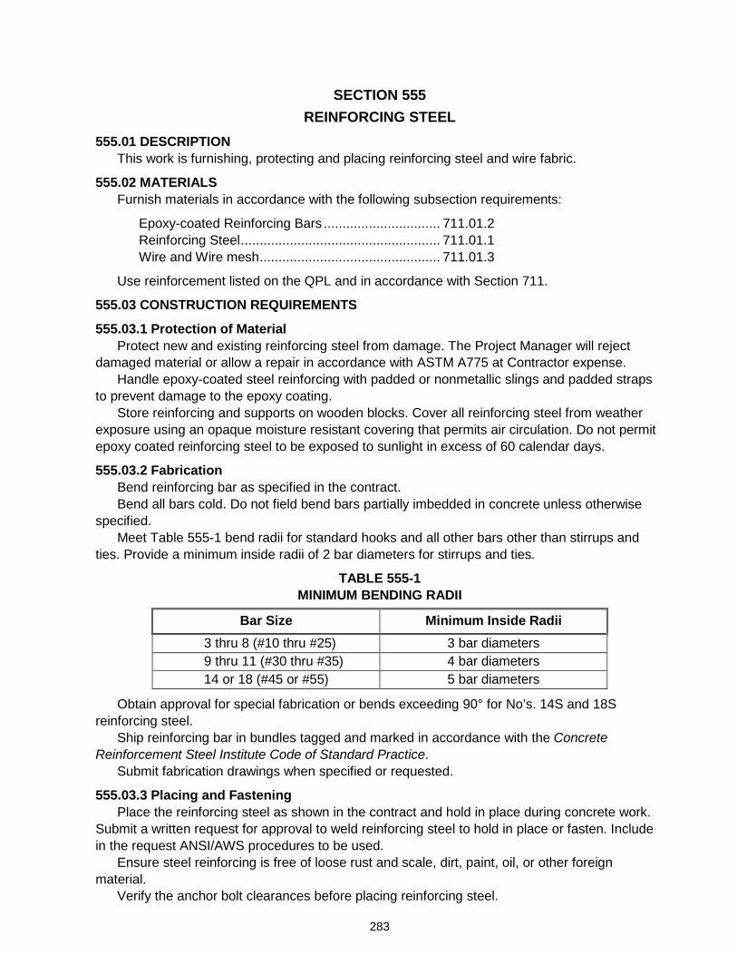
283
SECTION 555 REINFORCING STEEL
555.01 DESCRIPTION This work is furnishing, protecting and placing reinforcing steel and wire fabric.
555.02 MATERIALS Furnish materials in accordance with the following subsection requirements:
Epoxy-coated Reinforcing Bars ............................... 711.01.2 Reinforcing Steel ..................................................... 711.01.1 Wire and Wire mesh ................................................ 711.01.3
Use reinforcement listed on the QPL and in accordance with Section 711.
555.03 CONSTRUCTION REQUIREMENTS
555.03.1 Protection of Material Protect new and existing reinforcing steel from damage. The Project Manager will reject
damaged material or allow a repair in accordance with ASTM A775 at Contractor expense. Handle epoxy-coated steel reinforcing with padded or nonmetallic slings and padded straps
to prevent damage to the epoxy coating. Store reinforcing and supports on wooden blocks. Cover all reinforcing steel from weather
exposure using an opaque moisture resistant covering that permits air circulation. Do not permit epoxy coated reinforcing steel to be exposed to sunlight in excess of 60 calendar days.
555.03.2 Fabrication Bend reinforcing bar as specified in the contract. Bend all bars cold. Do not field bend bars partially imbedded in concrete unless otherwise
specified. Meet Table 555-1 bend radii for standard hooks and all other bars other than stirrups and
ties. Provide a minimum inside radii of 2 bar diameters for stirrups and ties.
TABLE 555-1 MINIMUM BENDING RADII
Bar Size Minimum Inside Radii 3 thru 8 (#10 thru #25) 3 bar diameters 9 thru 11 (#30 thru #35) 4 bar diameters 14 or 18 (#45 or #55) 5 bar diameters
Obtain approval for special fabrication or bends exceeding 90° for No’s. 14S and 18S reinforcing steel.
Ship reinforcing bar in bundles tagged and marked in accordance with the Concrete Reinforcement Steel Institute Code of Standard Practice.
Submit fabrication drawings when specified or requested.
555.03.3 Placing and Fastening Place the reinforcing steel as shown in the contract and hold in place during concrete work.
Submit a written request for approval to weld reinforcing steel to hold in place or fasten. Include in the request ANSI/AWS procedures to be used.
Ensure steel reinforcing is free of loose rust and scale, dirt, paint, oil, or other foreign material.
Verify the anchor bolt clearances before placing reinforcing steel.
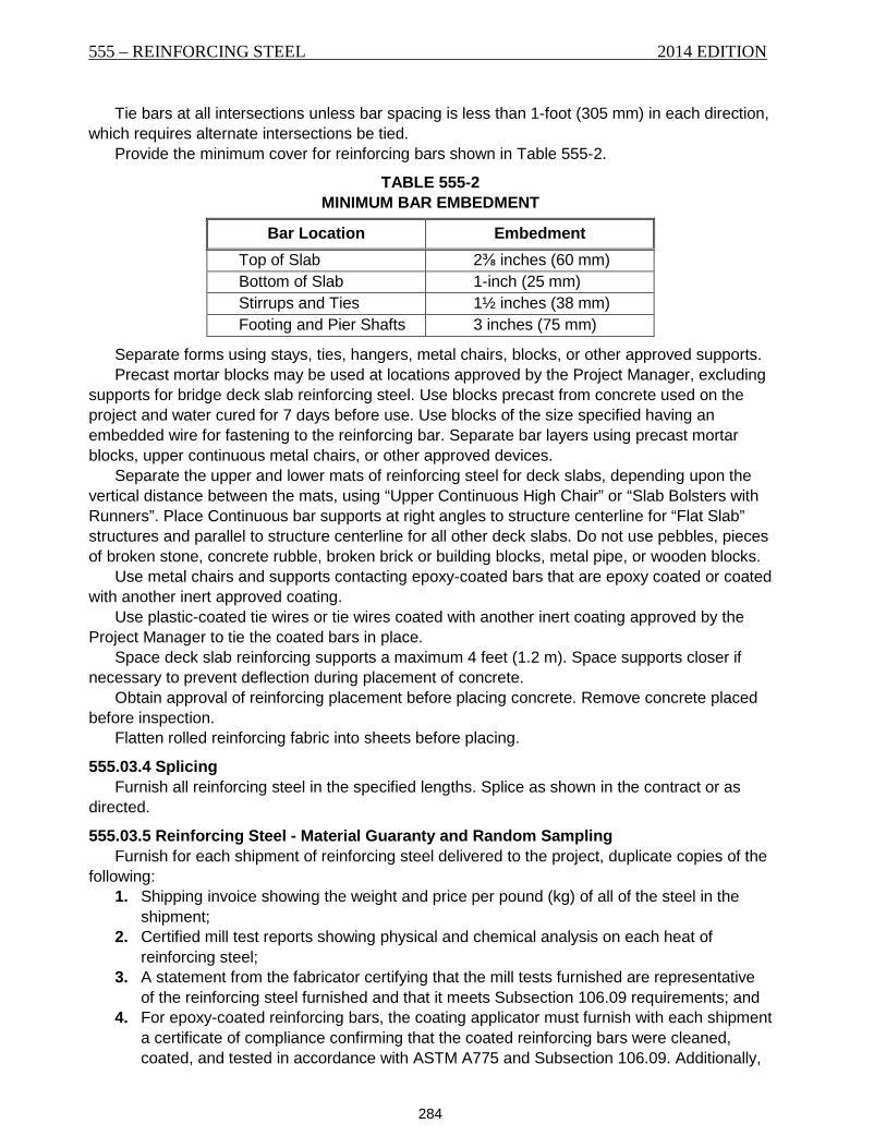
555 – REINFORCING STEEL 2014 EDITION
284
Tie bars at all intersections unless bar spacing is less than 1-foot (305 mm) in each direction, which requires alternate intersections be tied.
Provide the minimum cover for reinforcing bars shown in Table 555-2.
TABLE 555-2 MINIMUM BAR EMBEDMENT
Bar Location Embedment Top of Slab 2⅜ inches (60 mm) Bottom of Slab 1-inch (25 mm) Stirrups and Ties 1½ inches (38 mm) Footing and Pier Shafts 3 inches (75 mm)
Separate forms using stays, ties, hangers, metal chairs, blocks, or other approved supports. Precast mortar blocks may be used at locations approved by the Project Manager, excluding
supports for bridge deck slab reinforcing steel. Use blocks precast from concrete used on the project and water cured for 7 days before use. Use blocks of the size specified having an embedded wire for fastening to the reinforcing bar. Separate bar layers using precast mortar blocks, upper continuous metal chairs, or other approved devices.
Separate the upper and lower mats of reinforcing steel for deck slabs, depending upon the vertical distance between the mats, using “Upper Continuous High Chair” or “Slab Bolsters with Runners”. Place Continuous bar supports at right angles to structure centerline for “Flat Slab” structures and parallel to structure centerline for all other deck slabs. Do not use pebbles, pieces of broken stone, concrete rubble, broken brick or building blocks, metal pipe, or wooden blocks.
Use metal chairs and supports contacting epoxy-coated bars that are epoxy coated or coated with another inert approved coating.
Use plastic-coated tie wires or tie wires coated with another inert coating approved by the Project Manager to tie the coated bars in place.
Space deck slab reinforcing supports a maximum 4 feet (1.2 m). Space supports closer if necessary to prevent deflection during placement of concrete.
Obtain approval of reinforcing placement before placing concrete. Remove concrete placed before inspection.
Flatten rolled reinforcing fabric into sheets before placing.
555.03.4 Splicing Furnish all reinforcing steel in the specified lengths. Splice as shown in the contract or as
directed.
555.03.5 Reinforcing Steel - Material Guaranty and Random Sampling Furnish for each shipment of reinforcing steel delivered to the project, duplicate copies of the
following: 1. Shipping invoice showing the weight and price per pound (kg) of all of the steel in the
shipment; 2. Certified mill test reports showing physical and chemical analysis on each heat of
reinforcing steel; 3. A statement from the fabricator certifying that the mill tests furnished are representative
of the reinforcing steel furnished and that it meets Subsection 106.09 requirements; and 4. For epoxy-coated reinforcing bars, the coating applicator must furnish with each shipment
a certificate of compliance confirming that the coated reinforcing bars were cleaned, coated, and tested in accordance with ASTM A775 and Subsection 106.09. Additionally,
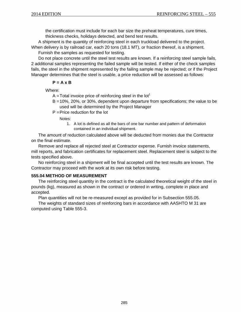
2014 EDITION REINFORCING STEEL – 555
285
the certification must include for each bar size the preheat temperatures, cure times, thickness checks, holidays detected, and bend test results.
A shipment is the quantity of reinforcing steel in each truckload delivered to the project. When delivery is by railroad car, each 20 tons (18.1 MT), or fraction thereof, is a shipment.
Furnish the samples as requested for testing. Do not place concrete until the steel test results are known. If a reinforcing steel sample fails,
2 additional samples representing the failed sample will be tested. If either of the check samples fails, the steel in the shipment represented by the failing sample may be rejected; or if the Project Manager determines that the steel is usable, a price reduction will be assessed as follows:
P = A x B
Where: A = Total invoice price of reinforcing steel in the lot1 B = 10%, 20%, or 30%, dependent upon departure from specifications; the value to be
used will be determined by the Project Manager P = Price reduction for the lot
Notes: 1. A lot is defined as all the bars of one bar number and pattern of deformation
contained in an individual shipment. The amount of reduction calculated above will be deducted from monies due the Contractor
on the final estimate. Remove and replace all rejected steel at Contractor expense. Furnish invoice statements,
mill reports, and fabrication certificates for replacement steel. Replacement steel is subject to the tests specified above.
No reinforcing steel in a shipment will be final accepted until the test results are known. The Contractor may proceed with the work at its own risk before testing.
555.04 METHOD OF MEASUREMENT The reinforcing steel quantity in the contract is the calculated theoretical weight of the steel in
pounds (kg), measured as shown in the contract or ordered in writing, complete in place and accepted.
Plan quantities will not be re-measured except as provided for in Subsection 555.05. The weights of standard sizes of reinforcing bars in accordance with AASHTO M 31 are
computed using Table 555-3.
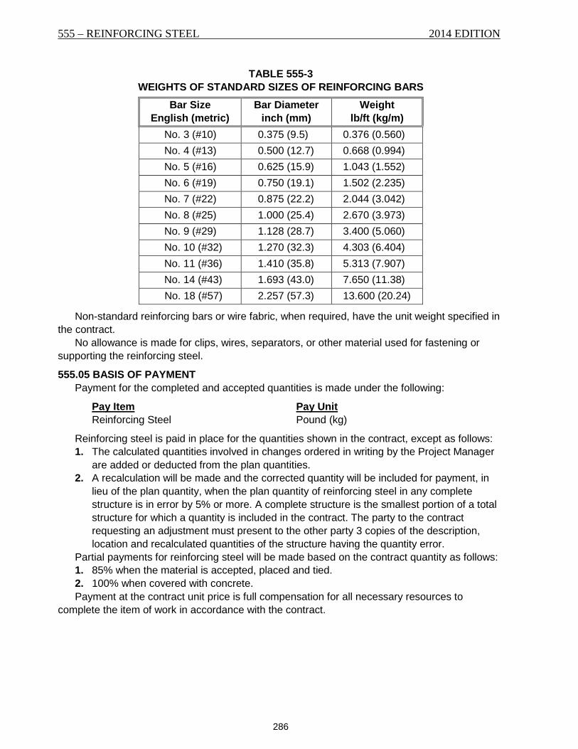
555 – REINFORCING STEEL 2014 EDITION
286
TABLE 555-3 WEIGHTS OF STANDARD SIZES OF REINFORCING BARS
Bar Size English (metric)
Bar Diameter inch (mm)
Weight lb/ft (kg/m)
No. 3 (#10) 0.375 (9.5) 0.376 (0.560) No. 4 (#13) 0.500 (12.7) 0.668 (0.994) No. 5 (#16) 0.625 (15.9) 1.043 (1.552) No. 6 (#19) 0.750 (19.1) 1.502 (2.235) No. 7 (#22) 0.875 (22.2) 2.044 (3.042) No. 8 (#25) 1.000 (25.4) 2.670 (3.973) No. 9 (#29) 1.128 (28.7) 3.400 (5.060) No. 10 (#32) 1.270 (32.3) 4.303 (6.404) No. 11 (#36) 1.410 (35.8) 5.313 (7.907) No. 14 (#43) 1.693 (43.0) 7.650 (11.38) No. 18 (#57) 2.257 (57.3) 13.600 (20.24)
Non-standard reinforcing bars or wire fabric, when required, have the unit weight specified in the contract.
No allowance is made for clips, wires, separators, or other material used for fastening or supporting the reinforcing steel.
555.05 BASIS OF PAYMENT Payment for the completed and accepted quantities is made under the following:
Pay Item Pay Unit Reinforcing Steel Pound (kg)
Reinforcing steel is paid in place for the quantities shown in the contract, except as follows: 1. The calculated quantities involved in changes ordered in writing by the Project Manager
are added or deducted from the plan quantities. 2. A recalculation will be made and the corrected quantity will be included for payment, in
lieu of the plan quantity, when the plan quantity of reinforcing steel in any complete structure is in error by 5% or more. A complete structure is the smallest portion of a total structure for which a quantity is included in the contract. The party to the contract requesting an adjustment must present to the other party 3 copies of the description, location and recalculated quantities of the structure having the quantity error.
Partial payments for reinforcing steel will be made based on the contract quantity as follows: 1. 85% when the material is accepted, placed and tied. 2. 100% when covered with concrete. Payment at the contract unit price is full compensation for all necessary resources to
complete the item of work in accordance with the contract.
287
SECTION 556 STEEL STRUCTURES
556.01 DESCRIPTION This work is the furnishing, fabricating, painting, and erecting of steel structures and the steel
structure portions of composite structures. The Department uses 490 pounds per cubic foot (7,850 kg/m3) to calculate the weight of
structural steel. The weights of rolled shapes and plates up to and including 36 inches (915 mm) in width are
computed based on their nominal weights and dimensions as shown on the shop drawings. One-half of the allowed percentage of overrun in weight as tabulated in ASTM A6 will be added to the nominal weights of plates exceeding 36 inches (915 mm) in width. The weight is computed on the basis of rectangular dimensions for all plates and overall lengths for all structural shapes with no deductions for copes, slips, sheared edges, punching, borings, milling, or planing. When parts can be economically cut in multiples from materials of larger dimension, the calculated weight is that of the material from which the parts are cut.
Bolts, nuts, and washer weights are the calculated weight in the AISC Manual of Steel Construction.
Weld metal weight is not computed.
556.02 MATERIALS Furnish materials in accordance with the following subsection requirements:
Bearing Assembly Anchor Bolts for Bridges ............ 711.13 Bolts and Nuts ......................................................... 711.07 Castings .................................................................. 711.12 Compression Joint Seals ......................................... 711.15 Elastomeric Bearing Devices................................... 711.14 Fiber-reinforced Pads for Bearing Plates ................. 711.16 Galvanized Metal .................................................... 711.08 High Strength Bolts ................................................. 711.06 Pins and Rollers ...................................................... 711.04 Structural Steel ....................................................... 711.02 Structural Steel Tubing ............................................ 711.03 Welding Electrodes ................................................. 711.05 Welded Stud Shear Connectors .............................. 711.09
556.03 CONSTRUCTION REQUIREMENTS For the fabrication of steel structures, follow AASHTO LRFD Bridge Construction
Specifications, unless otherwise specified in the contract.
556.03.1 Pre-Qualification for Steel Fabricators Use metal fabricators that are pre-qualified under the AISC Quality Certification Program for
the items listed below. The Department will make an exemption for new manufacturing plants that are of the same ownership as an existing certified plant, provided the new manufacturing plant operates under the same quality assurance and control programs as the certified plants, modified to address any production differences, and all fabrication is performed under the direct supervision of a quality assurance and control manager provided by an existing pre-qualified plant. Direct supervision means that the quality assurance and control manager is on site during all fabrication performed in the new fabrication plant and is responsible for the quality assurance and control activities. For new manufacturing plants, submit and receive approval of any
556 – STEEL STRUCTURES 2014 EDITION
288
proposed modifications to the parent plant’s quality assurance and control program prior to beginning production. Allow 30 business days from the date submitted for Department review and approval. Items not listed may be fabricated by non-certified shops. Use metal fabricators having the following AISC quality certification categories:
1. Use fabricators having Advanced Bridge certification to fabricate the following: a. Fracture critical members and attachments. Fabricators must have the Fracture
Critical Endorsement (F). b. Main members, (including spliced rolled beams). c. Welded floor beams. d. Diaphragms for horizontally curved girders.
2. Use fabricators having Intermediate Bridge certification to fabricate the following: a. Non-spliced rolled beams. b. Non-spliced floor beams. c. Diaphragms for straight girders (does not include diaphragms used for concrete
beams). 3. Use fabricators having a Simple, Intermediate, or Advanced Bridge certification to
fabricate the following: a. Modular expansion joints. b. Steel grid decking. c. Overhead sign bridge and cantilever sign structures. d. Lighting poles and anchor bases.
556.03.2 Submittals A. Fabrication Drawings. Prior to fabricating members, submit fabrication drawings to the
Project Manager. Include the following information: 1. An erection layout with each member assigned a production number; 2. A tentative fabrication schedule; 3. Denote any changes from the details in the contract; 4. All dimensions, geometrical information, details and other data required for
fabrication. Include camber information, blocking diagrams and shop splices; 5. Denote specification, grade, finish, required toughness testing and required surface
preparation for all steel plates, shapes, pipes, tubes, bars and all miscellaneous hardware such as shear studs, bolts, stud bolts, threaded rods, nuts and washers;
6. For galvanized items, identify the applicable specification. For painted items, specify paint type, manufacturer and recommended dried film thickness for each coat applied in the shop. Also identify surface preparation for each item to be painted. For paint requirements see Sections 612 and 710;
7. A list of field bolts and other items furnished by the fabricator: 8. Appropriate weld sizes, symbols, requirements for non-destructive testing, heat
cambering and bending procedures. Provide welding certifications and welding procedure specifications and any supporting documentation for all welding required for fabrication. For welding requirements see Section 624; and
9. Welding Procedure Specification (WPS) identification is required in the weld symbol tail for all weld symbols shown on the shop drawings.
Submit 5 copies of shop drawings on 11" x 17" or larger sheets and 5 copies of welding procedures and design calculations on 8½" x 11" or larger sheets to the Project Manager. Shop drawings, design calculations, and welding procedures may be furnished in Adobe Acrobat Reader (.pdf) format in lieu of the hard copies. Ensure the submittal includes all information required to check the structural accuracy and fabrication procedures for the structure.
2014 EDITION STEEL STRUCTURES – 556
289
Structural shop drawings must be designed, and stamped by a professional engineer registered and licensed to conduct engineering in the State of Montana.
Do not begin fabrication until the Department approved drawings are received by both the plant and the Department Inspector. Coordinate the fabrication schedule with the Department Inspector.
B. Certificate of Compliance. Furnish a manufacturer’s Certificate of Compliance for all bolts, nuts, washers and load indicator washers. Include certified mill test reports and test reports performed on the finished bolt confirming that all of the materials provided meet the requirements of the applicable AASHTO or ASTM specification. The documentation must include the name and address of the test laboratory, the date of testing, lot identification and the sample sizes of bolts and nuts used for each test performed for the certification.
Submit the following items to the Project Manager before installation: 1. One copy of the certification from the supplier showing that all tests required by the
AASHTO and ASTM specifications have been performed. Include the date and location of those tests, as well as the production lot numbers and the sample sizes used for each test performed with the certification.
2. One copy of the certification from the supplier, showing that the wedge tests and rotational capacity tests have been performed. Also show production lot numbers, dates, locations, and sample sizes of these tests and who performed them.
3. Three bolt, nut, and washer assemblies from each rotational capacity test lot for verification by the Department. Do not install fasteners prior to receiving approval.
556.03.3 Mill and Shop Inspection 1. Inspection of Work. Do not begin manufacturing or shop fabrication until the
Department’s Inspector has inspected the shop. 2. Facilities for Inspection. Furnish facilities for inspecting the material and workmanship
in the mill and shop. Allow the Inspector free access to the work at all times. 3. Inspector’s Authority. The Inspector may reject material or work not in accordance with
the specifications. In case of dispute, the Contractor may appeal the Inspector’s decision to the Project Manager.
4. Mill Test Reports. Furnish the Project Manager a complete certified mill test report showing chemical analysis and physical tests for each heat of steel for all members. Identify each piece of steel with a mark number on the mill test report.
5. Facilities for Testing. Furnish, at Contractor expense, test specimens, labor, testing machines, and tools to make the specimens and tests.
6. Rejections. Material or finished members accepted by the Inspector may be rejected if the material is subsequently found defective. Replace or repair rejected material at Contractor expense.
556.03.4 Storage and Handling of Materials Mark alloy and high-strength steels as required by the AASHTO LRFD Bridge Construction
Specifications. Mark material required to meet a Charpy requirement for identification. 1. Store materials off the ground and keep them clean and dry. 2. Place and store girders upright. 3. Support long members, including but not limited to columns, chords, and girders on
blocks spaced to prevent deflection. 4. Store high-strength fastener components in accordance with the manufacturer’s
recommendations.
556 – STEEL STRUCTURES 2014 EDITION
290
5. Store the bolts and nuts in the original containers until used. 6. Protect from dirt and moisture. 7. Remove only as many fasteners from protected storage as can be tightened during a
work shift and return unused fasteners to protected storage at the end of each work shift.
556.03.5 Quality Control Prepare and follow a quality control (QC) plan for ensuring the quality of all work and
conformance to specifications. Submit 1 copy of the QC plan to the Project Manager for review 30 calendar days prior to fabrication.
Ensure that all nondestructive testing (NDT) is performed by personnel qualified in conformance with the American Society for Nondestructive Testing (ASNT) Recommended Practice No. SNT-TC-1A to minimum Testing Level II for the individual methods. Ensure that the QC plan meets the following minimum requirements:
1. NDT, Radiographic Inspection. Inspect 100% of all complete joint penetration (CJP) groove welds.
2. NDT, Ultrasonic Inspection. Inspect 100% of all CJP groove welds on plates thicker than ¼-inch (6 mm).
3. NDT, Magnetic Particle Inspection. Randomly inspect 25% of all welding for each member throughout the entire structure in accordance with AWS D1.5 bridge welding code. The Project Manager reserves the right to select locations for testing.
4. Personnel qualifications. Include the qualifications of the specific individuals that will be performing the QC testing.
5. Quality control manager. Identify the QC manager that will be the primary contact person for all QC communication. Ensure that this person is in charge of all QC work.
Provide reports of all QC testing as the testing is completed. Identify in the reports any deviations from specifications, standards, or the QC plan and a discussion of why the deviation occurred.
At the completion of fabrication, and before shipment, provide a certification signed by the quality control manager that contains the following statement and supporting information:
Required Statement: “This is to certify that the quality control plan was followed and that the results of the quality control program indicate that the materials and the construction operations controlled by the quality control plan are in conformity with the approved plans and specifications. Exceptions to the plans, specifications, and quality control plan are described below.”
556.03.6 Pilot and Driving Nuts. Furnish 2 pilot nuts and 2 driving nuts for each size of pin unless otherwise specified. Pilot
and driving nuts are not required when shoes are assembled at the fabrication plant.
556.03.7 Bolts and Bolted Connections A. General. Make bolted connections in accordance with the contract requirements.
1. Furnish bolts that are free of rust. 2. When galvanized fasteners are specified, furnish assemblies manufactured with a
visible dye, so a visual check verifies the lubricant’s presence at installation. Use black fasteners oily to the touch at installation.
3. Use beveled washers to provide full bearing to the head or nut where bolts are used on beveled surfaces.
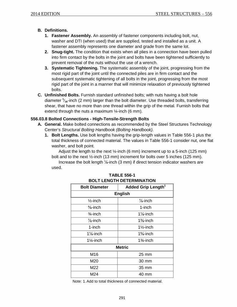
2014 EDITION STEEL STRUCTURES – 556
291
B. Definitions. 1. Fastener Assembly. An assembly of fastener components including bolt, nut,
washer and DTI (when used) that are supplied, tested and installed as a unit. A fastener assembly represents one diameter and grade from the same lot.
2. Snug-tight. The condition that exists when all plies in a connection have been pulled into firm contact by the bolts in the joint and bolts have been tightened sufficiently to prevent removal of the nuts without the use of a wrench.
3. Systematic Tightening. The systematic assembly of the joint, progressing from the most rigid part of the joint until the connected piles are in firm contact and the subsequent systematic tightening of all bolts in the joint, progressing from the most rigid part of the joint in a manner that will minimize relaxation of previously tightened bolts.
C. Unfinished Bolts. Furnish standard unfinished bolts; with nuts having a bolt hole diameter 1⁄16-inch (2 mm) larger than the bolt diameter. Use threaded bolts, transferring shear, that have no more than one thread within the grip of the metal. Furnish bolts that extend through the nuts a maximum ¼-inch (6 mm).
556.03.8 Bolted Connections - High-Tensile-Strength Bolts A. General. Make bolted connections as recommended by the Steel Structures Technology
Center’s Structural Bolting Handbook (Bolting Handbook). 1. Bolt Lengths. Use bolt lengths having the grip-length values in Table 556-1 plus the
total thickness of connected material. The values in Table 556-1 consider nut, one flat washer, and bolt point.
Adjust the length to the next ¼-inch (6 mm) increment up to a 5-inch (125 mm) bolt and to the next ½-inch (13 mm) increment for bolts over 5 inches (125 mm).
Increase the bolt length ⅛-inch (3 mm) if direct tension indicator washers are used.
TABLE 556-1 BOLT LENGTH DETERMINATION
Bolt Diameter Added Grip Length1 English
½-inch ⅞-inch ⅝-inch 1-inch ¾-inch 1⅛-inch ⅞-inch 1⅜-inch 1-inch 1½-inch
1⅛-inch 1⅝-inch 1¼-inch 1¾-inch
Metric M16 25 mm M20 30 mm M22 35 mm M24 40 mm
Note: 1. Add to total thickness of connected material.
556 – STEEL STRUCTURES 2014 EDITION
292
Where beveled washers are used, adjust bolt lengths to account for the use of nonstandard or beveled washers.
2. Bolted Parts. Ensure bolted surfaces in contact with the bolt head and nut do not have a slope of more than 1V:20H to a plane normal to the bolt axis.
Ensure bolted parts fit solidly when assembled. Provide a Class A finish, per AASHTO LRFD Bridge Construction Specifications
for all faying surfaces. 3. Washers. Install fastener assemblies with hardened washer(s) in accordance with the
Bolting Handbook. B. Pre-Installation. Submit 1 of the following bolt methods for use:
a. Turn of the nut, b. Calibrated wrench, c. Direct Tension Indicator (DTI), or d. Tension Control Bolts (twist-off)
1. Pre-Installation Verification Testing. Perform Pre-installation verification procedures in accordance with the Bolting Handbook. Retest when directed by the Project Manager.
2. Reuse of bolts previously tightened. Reuse of bolts previously tightened is not permissible except as described in the Bolting Handbook.
C. Production Bolting. Tighten bolts in accordance to the pre-tensioning procedures given in the Bolting
Handbook. Fully erect continuously supported girder sections between expansion joints before
production bolt tightening. Tightening is dependent upon consistency of torque and is dependent on condition of
the fastener assembly. Verify that the condition of assembly is similar to those used in the Pre-installation Verification test. Conditions of the assembly and the efficiency of the lubricant can be affected by the following:
1. Exposure to the elements during storage. 2. High temperatures during storage. 3. High temperatures during tightening. 4. Low temperatures during tightening. 5. Additional moisture from snow and rain during tightening. 6. Passing of time between the snugging operation and tightening. If these condition changes occur, repeat the pre-installation verification test on a
representative sample of fastener assemblies to be tightened. Lubricate bolts in accordance to the Bolting Handbook. Re-lubricating of tension
control bolts may only be performed by the manufacturer. D. Metric Bolt Substitution. Allowable bolt substitutions are shown in Table 556-2.
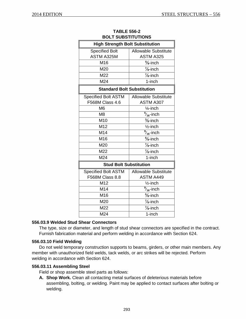
2014 EDITION STEEL STRUCTURES – 556
293
TABLE 556-2 BOLT SUBSTITUTIONS
High Strength Bolt Substitution Specified Bolt ASTM A325M
Allowable Substitute ASTM A325
M16 ⅝-inch M20 ⅞-inch M22 ⅞-inch M24 1-inch
Standard Bolt Substitution Specified Bolt ASTM
F568M Class 4.6 Allowable Substitute
ASTM A307 M6 ¼-inch M8 5⁄16-inch M10 ⅜-inch M12 ½-inch M14 9⁄16-inch M16 ⅝-inch M20 ⅞-inch M22 ⅞-inch M24 1-inch
Stud Bolt Substitution Specified Bolt ASTM
F568M Class 8.8 Allowable Substitute
ASTM A449 M12 ½-inch M14 9⁄16-inch M16 ⅝-inch M20 ⅞-inch M22 ⅞-inch M24 1-inch
556.03.9 Welded Stud Shear Connectors The type, size or diameter, and length of stud shear connectors are specified in the contract. Furnish fabrication material and perform welding in accordance with Section 624.
556.03.10 Field Welding Do not weld temporary construction supports to beams, girders, or other main members. Any
member with unauthorized field welds, tack welds, or arc strikes will be rejected. Perform welding in accordance with Section 624.
556.03.11 Assembling Steel Field or shop assemble steel parts as follows: A. Shop Work. Clean all contacting metal surfaces of deleterious materials before
assembling, bolting, or welding. Paint may be applied to contact surfaces after bolting or welding.
556 – STEEL STRUCTURES 2014 EDITION
294
Shop assemble and adjust to line and camber all bolted trusses, continuous plate girders, curved steel elements, box girders, I-beam spans, skew portals, skew connections, rigid frames, bents, and towers.
Drill and ream the field splice holes during assembly. Holes for other field connections may be shop drilled or reamed with the connecting parts assembled or drilled or reamed to metal templates with hardened bushings, without assembling.
Use an approved alternate procedure where shop space prevents complete shop assembly of continuous span girders or trusses. The procedure may require adjusting the line and camber of at least two abutting sections of girder for drilling or reaming of field splices if all girder lines for the complete structure are assembled consecutively.
Field butt joints for welded girders may be assembled with abutting members adjusted for line and camber and prepared to fit for welding, subject to Project Manager approval.
Bridge expansion devices must be initially shop assembled to establish the proper fit between the joint parts.
B. Field Work. Assemble the parts as specified in the contract, following the match-marks. Prevent damaging the material while handling. Clean all bearing and member surfaces in permanent contact before assembly.
Splices and field connections must have a minimum of ½ of the holes filled with bolts or erection pins before removing temporary supports or releasing the load from erecting equipment. Splices and connections carrying traffic during erection must have ¾ of the holes pinned or bolted.
Do not begin production bolt tightening of the field splice bolts until the complete girder line is aligned and erected matching the full camber line.
Use erection pins 1⁄32-inch (1 mm) larger than the nominal diameter of the permanent bolts.
Erect truss spans on blocking, unless they are erected using the cantilever method, to provide truss camber. Leave the blocking in place until the tension cord splices are fully bolted and all other truss connections pinned and bolted. Do not tension bolts in butt joint splices of compression members and in railings until the span is swung.
C. Drifting of Holes. Only use drift pins during assembly to the extent necessary to bring the parts into position without enlarging or distorting the holes or metal. Do not ream holes during field fitting without approval from the Project Manager.
D. Match-marking. Match-mark parts assembled in the shop for reaming field connection holes and furnish the Project Manager a diagram showing the marks.
556.03.12 Marking and Shipping Paint or mark each member with an erection mark, and furnish the Project Manager an
erection diagram detailing the erection marks. Furnish copies of material orders, shipping statements, and erection diagrams. Show the
individual member weights on the statements. A shipping statement must accompany the material and be marked to clearly identify it with
the delivered material and mill test reports. Mark the weight on members weighing 3 tons (2.7 MT) or more. Load and unload structural
members on trucks or cars without stressing or causing damage. Pack bolts, loose nuts or washers of each size separately. Ship pins, small parts, bolts,
washers, and nuts in boxes, crates, kegs, or barrels, with the gross weight of each package not exceeding 300 pounds (136 kg). Plainly mark each shipping container, listing and describing the contents on the outside of each shipping container.
2014 EDITION STEEL STRUCTURES – 556
295
Keep structural material clean and free from damage.
556.03.13 Painting Clean and paint all iron and steel surfaces in accordance with Section 612.
556.03.14 Erection Furnish a steel erection plan and specifications that ensures safety, prevents overstressing
of the steel, maintains stability, prevents damage to the work or surroundings, and achieves the proper final geometry. Furnish a complete erection plan and specifications for erection of the steel and for any falsework necessary, including temporary bracing, guy-wires, or other required items to the Project Manager a minimum of 14 calendar days prior to construction of the superstructure.
The erection plan and specifications must bear the signature and the professional seal of a professional engineer licensed to practice in Montana.
556.03.15 Falsework Design, construct, and maintain falsework to support the maximum construction loadings.
Check and approve falsework drawings before submitting. The Department has 20 business days to review and return the falsework drawings. The contract time will be extended day for day for any delay beyond the 20-day review period if the Department’s delay affects the Contractor’s operation as shown on the current work schedule.
556.03.16 Bearing and Anchorage Place masonry bearing plates in accordance with Subsection 565.03.2.
556.03.17 Placing Anchor Bolts Place anchor bolts in accordance with Subsection 552.03.13.
556.03.18 Straightening Bent Material Straighten bent plates, angles or other shapes without damaging the material. The metal
may be heated if approved. Do not exceed 1,000 °F (537 °C). Once heated, cool the metal slowly.
All straightened metal will be inspected for defects.
556.03.19 Pin Connections Furnish the Project Manager the pilot and driving nuts provided with the steelwork once the
work is complete. The members must take full bearing on the pins. Bring pin nuts up tight, and burr the threads at the nut face.
556.03.20 Misfits Correct all misfits, errors, and injuries as a part of the assembly and erection work. Report to
the Project Manager all shop work errors that prevent the assembly and fitting of parts with a minimum use of drift pins, reaming, slight chipping or cutting. Obtain Department approval for the correction method. Corrections must be inspected and approved.
556.03.21 Cleanup Remove all falsework, excavated or unused materials, rubbish, and temporary buildings.
Restore all public and private property damaged during construction to its original condition. Pull, cut off or otherwise remove all falsework piling 1-foot (305 mm) below finished the
ground line or streambed, unless otherwise directed. Perform all work affecting the stream channel in accordance with Subsection 208.03.4 before final acceptance.
556 – STEEL STRUCTURES 2014 EDITION
296
556.03.22 Rejections An Inspector’s acceptance of material or finished members does not prevent later rejection if
defects are found. Replace or repair rejected material and work at Contractor expense.
556.04 METHOD OF MEASUREMENT Structural steel is measured by the lump sum.
556.05 BASIS OF PAYMENT Payment for the completed and accepted quantities is made under the following:
Pay Item Pay Unit Structural Steel Lump Sum
The weight of structural steel in the contract is an estimate only. No guarantee is made that the estimated weight is the correct weight to be furnished. No adjustment in the contract unit price is made if the weight furnished is more or less than the estimated weight.
If changes in the work ordered by the Project Manager vary the weight of steel to be furnished, the lump sum payment is adjusted as follows:
The value per pound (kg) of a decrease or increase in the weight of structural steel involved is determined by the following:
Value per Pound (kilogram) = Contract Lump Sum Bid Estimated Contract Weight
The adjusted contract lump sum amount paid is the contract lump sum bid plus or minus the value of steel involved in the change.
Should the ordered change materially alter the character of the work and the unit cost, compensation for that work is made at an agreed price established before the work is performed. Detail in writing, the changes in procedures and the resulting costs for labor, equipment, and materials to support the agreed price.
Partial payments for structural steel will be made based on the lump sum contract unit price as follows:
1. 90% when erected. 2. 97% when bolted and spot painted. 3. 100% when painted in compliance with the plans and specifications. Payment at the contract unit price is full compensation for all resources necessary to
complete the item of work in accordance with the contract.
297
SECTION 557 STEEL BRIDGE RAILING
557.01 DESCRIPTION This work is the furnishing and installing of steel bridge railing.
557.02 MATERIALS Furnish materials in accordance with the following subsection requirements:
Fiber-reinforced Pads for Rail Post Base Plates ...... 711.16 Galvanized Metal .................................................... 711.08 High Tensile Strength Anchor Bolts ......................... 711.06 Steel Beam Guardrail and Wood Blocks ................. 705.01 Structural Steel ....................................................... 711.02 Structural Steel Tubing ............................................ 711.03
557.03 CONSTRUCTION REQUIREMENTS
557.03.1 Fabrication Drawings Furnish fabrication drawings for steel bridge railing in accordance with Subsection 556.03.2.
557.03.2 Fabrication Fabricate steel bridge railing in accordance with Section 556.
557.03.3 Erection Construct steel bridge railing as shown in the contract. Adjust the completed railing to
compensate for any unevenness in the structure. Ensure all rail posts are vertical. Do not place railing on a span until centering or falsework is removed. Place rail post base plates on fiber-reinforced pads, sized and positioned to project a minimum ½-inch (13 mm) on all sides of the base plates.
557.03.4 Painting Clean and paint steel bridge railing specified to be painted in accordance with Section 612.
557.04 METHOD OF MEASUREMENT Steel bridge railing of the type or types specified is measured by the foot (m). Measurement
is based on the computed horizontal distance between the centerlines of end base plates.
557.05 BASIS OF PAYMENT Payment for the completed and accepted quantities is made under the following:
Pay Item Pay Unit Bridge Railing Foot (m)
Partial payments of steel bridge railing will be made based on the total quantity as follows: 1. 90% when erected. 2. 95% when bolted and spot painted. 3. 100% when painted in compliance with the contract. Payment at the contract unit price is full compensation for all resources necessary to
complete the item of work in accordance with the contract.

557 – STEEL BRIDGE RAILING 2012 EDITION
298
299
SECTION 558 DRILLED SHAFTS
558.01 DESCRIPTION This work is constructing reinforced concrete shafts cast in cylindrically excavated holes that
extend into soil or rock to support the structure and externally applied loads at the locations and to the lines and grades shown in the contract.
558.02 MATERIALS
558.02.1 Drilled Shaft Concrete Use Drilled Shaft Concrete for all concrete placed between the bottom of the shaft and the
top of the casing, unless otherwise shown in the contract. Obtain the Project Manager’s approval before using a SCC mix design.
558.02.2 Permanent Drilled Shaft Casing Furnish casing in accordance with the size and thickness requirements specified and casing
material that meets the requirements of AASHTO M 270, Grade 36. Furnish, fabricate and inspect casing materials in accordance with Section 556.
558.03 CONSTRUCTION REQUIREMENTS
558.03.1 Submittals Submit 4 copies of the following information to the Project Manager a minimum of 30
calendar days before start of drilling operations. A. Drilled Shaft ASC and WN outlining:
1. Bent and shaft construction sequence. If more than one shaft will be worked on at any time, include that information in the submittal.
2. Method of shaft excavation. 3. Method to clean shaft excavation. 4. Temporary and permanent casing installation and removal methods. Include casing
top and bottom elevations and diameters. 5. The effects of hydrostatic pressure differentials that may occur during excavation and
shaft construction. Include a description of procedures relating to hydrostatic effects that will be used to ensure that the stability of the excavation is not compromised.
6. Method of concrete placement. State the planned initial elevation of the bottom of placement pipe. Provide descriptions of methods or devices used to prevent the injection of air or water into the drilled shaft concrete when starting concrete placement and in the event the placement is stopped and restarted. Include descriptions of methods or devices that will be used to control the rate of concrete discharge in order to minimize turbulence that could result in concrete washout or other detrimental effects.
7. Time necessary for complete concrete placement. B. Name and experience record of Contractor, and Superintendent and driller(s) to that will
perform the drilled shaft work on this project. Include all experience in the last 10 years. C. List of proposed drilling equipment to be used, including any cranes, drills, augers, bits,
temporary casings and cleaning tools. Include diameter of augers and cleaning buckets. D. Proposed size and location of all reinforcing steel used to support or maintain the shape
of the reinforcing steel cage.
558 – DRILLED SHAFTS 2014 EDITION
300
558.03.2 Shaft Pre-construction Meeting Schedule a shaft pre-construction meeting with the Project Manager for a time 7 to 14
calendar days prior to drilling. The minimum required attendees are the superintendent, concrete supplier, and Project Manager. The purpose of the meeting is to review the requirements of this specification, discuss the drilled shaft installation plan, and to discuss logistical and contingency plans.
558.03.3 Geotechnical Logging The Department may provide a geotechnical representative on-site during drilling and
installation operations to log the excavation. Notify the Project Manager at least 7 calendar days prior to start of drilled shaft excavation so that the Project Manager may schedule the on-site representative.
558.03.4 Shaft Excavation Use excavation methods that provide contact with firm, undisturbed soil or rock with the sides
and bottom of the shaft concrete when the temporary casing is removed. Do not excavate holes larger than the outside diameter of permanent casings.
558.03.5 Shaft Locations, Alignment and Tolerances Drill all shafts to the bottom elevations specified or as directed by the Project Manager.
Construct the shaft so the vertical centerline axis of the finished shaft is within 3 inches (75 mm) of the plan location at the top of the shaft. Drill all shafts to within 2% of vertical the entire depth of the shaft excavation.
558.03.6 Sloughing and Caving Use tools and tool withdrawal rates that will not cause suction effects that result in soil
intrusion or instability of the excavation. Use construction methods that will ensure no sloughing or caving of the shaft side walls. In the event any sloughing or caving does occur, remove all sloughed material. Ensure that concrete completely fills the shaft. If caving occurs during placement of drilled shaft concrete, immediately stop the flow of concrete and undertake corrective measures to completely remove the sloughed materials from the shaft. If necessary to facilitate material removal, remove the concrete and reinforcing steel already placed in the shaft.
558.03.7 Permanent Casing A. Furnish and install permanent casing when specified in the contract. Permanent casing
remains in place and is included in the design of the drilled shaft. The permanent casing diameter may be oversized up to 3 inches (75 mm) if necessary to facilitate temporary casing installation.
B. If field welding, submit 4 copies of the weld procedures to the Project Manager for approval 30 calendar days prior to welding.
C. Provide corrosion protection for all permanent casing. Galvanize the permanent casing to AASHTO M 111 and ASTM A653 specifications or paint. If painting, meet the following requirements: 1. Furnish paint in accordance with Subsection 710.02(B)(3). 2. Prepare the casing surface following the paint manufacturer’s recommendations. 3. Follow the paint manufacturer’s recommendations for paint application. Apply paint to
the casing before installation, starting 24 inches (610 mm) below ground surface, continuing to the top of exposed steel.
4. Apply the first two paint coats to produce a minimum 12 mil (0.300 mm) dry film thickness. Provide 2 copies of the painter’s certification that the paint was applied following the manufacturer’s recommendations and the paint coat thickness on the casing.
2014 EDITION DRILLED SHAFTS – 558
301
5. Repair paint damage caused by transport, handling and welding following the paint manufacturer’s recommendations before applying the finish coat.
For the finish coat, use the same paint or paint compatible with the first 2 coats. Provide a finish coat with a minimum 3 mil (75 µm) dry film thickness. Provide the finish coat paint that meets Federal specification 595B, pigment code 36440 (concrete gray).
558.03.8 Temporary Casing Do not use slurry construction methods as an alternative to or in conjunction with temporary
casing unless specified in the contract. Use temporary casing to facilitate shaft construction and prevent sloughing and caving of the shaft sidewalls. Place temporary casing to a minimum elevation as shown in the contract. Place the temporary casing deeper if necessary to prevent material from entering the shaft excavation. Use casing with an outside diameter no less than the specified diameter of the shaft. Limit the excavation in advance of the casing tip to no more than 10 feet (3 m) unless synthetic slurry is being used. During casing extraction, maintain a sufficient level of fluid in the casing to counteract external hydrostatic pressures but no less than 5 feet (1.5 m) of positive head. Maintain an adequate level of concrete within the casing to ensure that fluid trapped behind the casing is displaced upward and discharged at the ground surface without contaminating or displacing the shaft concrete. Temporary casings that have become bound or fouled during shaft construction and cannot be removed are considered to be a defect in the drilled shaft. Correct defective shafts using approved methods at no cost to the Department. Corrective action may consist of, but is not limited to, the following:
1. Removing the drilled shaft concrete and extending the drilled shaft deeper to compensate for the loss of frictional capacity to the cased zone.
2. Providing straddle drilled shafts to compensate for capacity loss. 3. Providing a replacement drilled shaft.
558.03.9 Obstructions An obstruction is defined as a specific object (including, but not limited to, boulders, logs, and
man-made objects) encountered during the shaft excavation which prevents the advance of the shaft excavation. If an obstruction is encountered promptly notify the Project Manager. Submit 4 copies of a proposed obstruction removal method to the Project Manager for approval within 2 business days of encountering the obstruction.
558.03.10 Cleaning Remove all loose or disturbed material from the bottom of the shaft excavation immediately
prior to placing reinforcing steel and concrete. After cleaning, no more than 1-inch (25 mm) of loose or disturbed material permitted in the bottom of the shaft. Maintain a sufficient level of fluid to counteract external hydrostatic pressures but no less than 5 feet (1.5 m) of positive head.
558.03.11 Installation of Cross-hole Sonic Logging (CSL) Tubes Install the CSL access tubes evenly spaced around the reinforcing cage and inside of all
hoops and spiral reinforcing steel, as shown in the contract. Use 1½-inch (38 mm) nominal diameter schedule 40 PVC CSL access tubes. Provide an end plug at the lower end of the pipe and make all joints watertight. Ensure tubes extend to the shaft bottom. In the event that CSL access tubes are not installed to the shaft bottom, the Department may require coring of the shaft to verify shaft integrity at Contractor’s expense. Fill the CSL access tubes with a 1:1 mixture of potable water and biodegradable antifreeze prior to or immediately after placing concrete in the drilled shaft. Temporarily cap the top of the tubes to prevent debris or concrete from entering the tubes. Clean any spilled antifreeze from the reinforcing steel and CSL tubes.
558 – DRILLED SHAFTS 2014 EDITION
302
558.03.12 Reinforcing Steel Tie bars at all intersections. After inspection and approval of the drilled shaft excavation by
the Project Manager, place the reinforcing steel cage into the shaft as one unit. Support the steel cage from the top so that racking and distortion are prevented. Remove internal stiffeners as necessary as the steel cage is placed in the excavation to prevent interference with the placement of concrete. Use non-corrosive, roller-type spacers or other non-corrosive devices as approved by the Project Manager along the steel cage length and around the steel cage perimeter to align and maintain clearance from reinforcing cage to edge of casing during concrete placement. Begin placing the drilled shaft concrete immediately after the Project Manager has inspected and approved the location and alignment of the cage within the drilled shaft. Remove the steel cage and re-inspect the excavation if the concrete placement is not started within 3 hours of placing the steel cage in position.
558.03.13 Concrete Placement Record Complete the Department’s Drilled Shaft Concrete Placement Log. Accurately record all data
required on the form as the concrete is placed. After the drilled shaft concrete has been placed and before the end of the day, furnish the completed form to the Project Manager. The Department will provide copies to the Contractor upon request.
558.03.14 Drilled Shaft Concrete Place concrete in the drilled shaft as specified for either dry excavations or wet excavations. A. Dry Excavations. Place concrete by gravity tremie tube or pumping. Concrete may free
fall into the shaft if the concrete can be directed so that it does not strike the reinforcing steel, the excavation wall or any other obstruction during the fall.
B. Wet Excavations. 1. Place all drilled shaft concrete by tremie tube, pumping, or other approved method to
avoid separation and segregation of the concrete mix components. 2. Separate the first concrete placed from the fluid in the excavation using a plug in the
tube, or other approved device. 3. Begin concrete placement in a manner that minimizes mixing of the concrete with the
water and material in the shaft. 4. Maintain a minimum 10 feet (3 m) of tremie pipe embedment and continuously place
drilled shaft concrete to ensure upward displacement of all contaminated concrete. If at any time during the placement, it is necessary to temporarily stop or the tremie pipe orifice is removed from the concrete, stop and restart concrete placement in a manner that ensures that air, water, or other undesirable material is not allowed to be mixed into the concrete or incorporated into the drilled shaft. Concrete that is discharged above the rising concrete level in the shaft is considered undesirable material.
5. Once concrete has reached the top of the drilled shaft, remove and dispose of the top layer of concrete and any concrete contaminated with mud or fluid from the drilled shaft. Remove sufficient concrete to fully expose sound, homogeneous and uncontaminated concrete in the shaft.
558.03.15 Shaft Testing and Acceptance A. Cross-Hole Sonic Logging. The Project Manager may use CSL to check the structural
soundness of any completed drilled shaft. The CSL testing will be performed when the concrete has cured sufficiently to give consistent test readings. Schedule construction activities to allow twelve calendar days from the time concrete is placed in the shaft until the shaft is tested. Provide a stable 110-Volt AC or a 12-Volt DC electrical supply if requested. When the CSL testing access tubes are no longer needed for testing, as
2014 EDITION DRILLED SHAFTS – 558
303
determined by the Project Manager, cut off the tubes flush with the top surface of the drilled shaft and remove the antifreeze solution to a depth of 4 inches (100 mm) from the top of the tubes. Permanently cap the CSL access tubes to provide a watertight seal that does not interfere with the subsequent construction operations. The Project Manager will accept or reject the shaft based on the CSL testing or a subsequent drilled core sample. For any drilled shaft determined by CSL testing to be of uncertain quality, drill core samples with a minimum diameter of 2½ inches (65 mm), at locations and to depths specified by the Project Manager. Use a core drilling method that provides complete core recovery and minimizes abrasion and erosion of the core. Grout all core holes when directed by the Project Manager.
B. Corrective Action. If the CSL or subsequent coring identifies any defect in the shaft that compromises the capacity of the shaft; repair the shaft by a method approved by the Project Manager. Submit a repair plan no later than 14 calendar days after notification. Include 4 copies of calculations and working drawings, stamped by a professional engineer licensed in Montana, to the Project Manager. Furnish all materials and work necessary to correct shaft defects at Contractor expense. Prior to constructing other shafts, submit 4 copies of a written proposal to the Project Manager that describes changes in construction methods or materials designed to avoid defects in subsequent drilled shafts.
558.04 METHOD OF MEASUREMENT
558.04.1 Drilled Shaft Drilled shaft will be measured by the linear foot (m) of shaft between the actual bottom
elevation of the drilled shaft and the top of shaft elevation shown on the contract.
558.04.2 Drilled Shaft Concrete Drilled shaft concrete will be measured by the cubic yard (m3) of concrete placed calculated
from the planned cross sectional area times the as built length of the drilled shaft.
558.04.3 Reinforcing Steel Drilled shaft reinforcing steel will be measured by the pound (kg) in accordance with
Subsection 555.04.
558.04.4 Drilled Shaft Casing Permanent drilled shaft casing will be measured by the linear foot (m) of permanent casing
installed as shown in the contract or as directed by the Project Manager in writing.
558.04.5 Temporary Casing When the Contract contains the pay item Temporary Drilled Shaft Casing, temporary drilled
shaft casing will be measured by the linear foot (m) of temporary casing measured from the higher of the ground or water surface elevation down to the bottom elevation of the installed temporary casing.
558.04.6 CSL Tubes and Testing Include all costs associated with furnishing and installing CSL access tubes and any required
extensions and providing a power source in the Drilled Shaft pay item. No measurement or payment will be made for construction delays resulting from the initial CSL drilled shaft testing. The Department will extend the contract time by 1 day for each day over 12 calendar days required to complete the CSL drilled shaft testing. The Department will pay the costs for the initial CSL drilled shaft testing. Pay for all costs associated with coring, engineering design, cost required to correct the defect and any construction delay costs, if a defect is found based on the CSL drilled shaft testing or coring. Pay the costs of CSL drilled shaft retesting of the repaired
558 – DRILLED SHAFTS 2014 EDITION
304
drilled shafts. If no defect is found in the drilled shaft based on the coring, the Department will pay all costs of coring and any delays necessitated by the coring.
558.05 BASIS OF PAYMENT Payment for the completed and accepted quantities is made under the following:
Pay Item Pay Unit Drilled Shaft Linear Foot (m) Reinforcing Steel Pound (kg) Drilled Shaft Casing Linear Foot (m) Drilled Shaft Concrete Cubic Yard (m3)
Payment at the contract unit price is full compensation for all resources necessary to complete the item of work in accordance with the contract. Temporary casings remain the property of the Contractor.
If the Contract contains the pay item Temporary Drilled Shaft Casing, all costs associated with temporary casing including, but not limited to, procurement, fabrication, transportation, installation and removal, are included in the pay item Temporary Drilled Shaft Casing. If the Contract does not contain the pay item Drilled Shaft Temporary Casing, no measurement or payment will be made. Include all costs associated with temporary casing including, but not limited to, fabrication, providing, transporting, installation and removal in the Drilled Shaft pay item.
Payment for obstruction removal will be made on a force account basis.
305
SECTION 559 PILING
559.01 DESCRIPTION This work consists of furnishing and placing piling.
559.02 MATERIALS Furnish materials in accordance with the following section and subsection requirements:
Hydraulic Cement Concrete .................................... 551 Steel Pipe Piles ....................................................... 711.10.2 Structural Steel Piles ............................................... 711.10.1
559.02.1 Inspection of Steel Pile Steel pile may be inspected at the rolling mill and will be inspected at the project. Furnish copies of the mill test reports showing the chemical and physical test results for each
steel pile heat number included in the shipment. Provide steel pile with a maximum camber or sweep of 0.013 inches per foot (1 mm/m) of
pile length. Store and handle steel piles to prevent damage. Bent, deformed, or kinked piles will be
rejected.
559.02.2 Furnish Pile Furnish pile quantities shown in the contract. The specified lengths are those required below cutoff. Adjust lengths for the difference
between the cut off length and the pile position in the driving equipment and as necessary to meet the requirements of Subsection 559.02.5. Increase pile lengths 1.0-foot (305 mm) for steel pile. Remove and dispose of excess pile length after the pile is driven.
559.02.3 Metal Pile End Protection Furnish prefabricated cast steel driving point or cutting shoe conforming to AASHTO M 103
requirements. Furnish cast steel driving point for H-pile. Furnish cast steel inside-flanged, open-end cutting shoe or 60°, inside-flanged conical driving point for pipe pile as specified. Weld driving point or cutting shoe to steel pile in accordance with ANSI/AASHTO/AWS D1.1 or D1.5, as applicable. Use welders certified by the Department or a Certified Welding Inspector.
559.02.4 Splicing Piles When directed by the Project Manager, splice piles driven to plan grade that do not obtain
the required driving resistance and continue driving until the required bearing resistance is obtained. Weld steel pile in accordance with AWS D1.5 requirements. Use 10-foot (3-m) minimum spacing for steel pile splice welds. When steel piles are driven less than 10 feet (3 m) below the cutoff elevation specified, use 1 splice to obtain the required cutoff elevation.
559.02.5 Holes in Piling Pile segments with 1 drilled hole having a diameter of ⅞-inch (22 mm) or less in any cross-
section may be incorporated into the finished structure. Pile with more than 1 hole in a cross-section, flame cut hole(s), or a hole greater than ⅞-inch (22 mm), must be cut off to remove the hole(s).This requirement does not apply to holes drilled for attaching dynamic testing equipment, holes shown in the contract or holes within 12 inches (305 mm) of the cutoff elevation.
559 – PILING 2014 EDITION
306
559.03 CONSTRUCTION REQUIREMENTS
559.03.1 Equipment for Driving Pile A. Pile Hammers. Drive piles with impact hammers that include air, steam, diesel or
hydraulic hammers. For air or steam hammers, provide equipment that maintains the volume as specified
by the manufacturer of the hammer as the pile is driven. Provide equipment with accurate pressure gauges that are easily read from ground level. Ensure that the striking parts of the hammer are at least ⅓ the weight of the helmet and the pile being driven or 2,750 lbs. (1,250 kg), whichever is greater.
Provide open-end (single-acting) diesel hammers with rings or other indicators on the ram that permit visual determination of the hammer stroke as the pile is driven. Submit a copy of the hammer manufacturer’s chart that equates the stroke and blows per minute for the hammer being used.
Provide closed-end (double-acting) hammers with an accurate bounce chamber pressure gauge that is easily read from ground level. Submit a copy of a chart, calibrated to the actual hammer performance that equates the bounce chamber pressure to the equivalent energy or stroke of the hammer.
Provide equipment for hydraulic hammers that are sized to maintain the manufacturer’s specified volume and pressure during driving. Provide equipment with accurate pressure gauges that are easily read from ground level.
Delays and additional costs resulting from load tests or other extra work required to verify approval of the vibratory hammer or driving aids is at Contractor expense. If a vibratory hammer is used, re-drive each pile with an impact hammer having the energy to verify the required bearing resistance during driving, as required in Subsection 559.03.3.
B. Pile Driving Aids and Accessories. 1. Followers. Do not use followers. 2. Helmet. Provide metal helmets for pile to be driven by impact drivers. Helmets must
fit around the pile top, align axially with the hammer and pile, distribute the hammer energy to the total pile head cross section and have leads to guide them.
3. Hammer Cushion. When driving pile with an impact hammer, use a cushion to prevent damage to the pile and hammer. Use a cushion recommended and approved by the hammer manufacturer. Use a striker plate recommended by the hammer manufacturer on the hammer cushion to provide uniform compression of the cushion material.
4. Leads. Support the piles in line and position during driving. Use pile hammer leads that permit free movement of the hammer, maintain hammer and pile alignment and provide concentric impact for each blow.
5. Jets. Do not use water jets. 6. Caps. Follow the pile manufacturer’s recommendations regarding caps, driving
heads, mandrels or other required devices. C. Pile Pre-drilling. When specified in the contract, use the prescribed drilling methods
discussed in this specification. Do not impair the bearing resistance of previously installed pile or the safety of adjacent structures. If drilling reduces the bearing resistance of previously placed pile, restore the disturbed pile to conditions in accordance with this specification by re-driving after drilling operations in the area have been completed. 1. Pile Pre-bore. When pile pre-bore is specified, use an auger, wet-rotary drill or other
approved method. Drill pre-bore holes to the specified diameter and depth. Drive the pile in the pre-bore hole, starting from the bottom of the hole, with an impact hammer
2014 EDITION PILING – 559
307
evaluated in accordance with Subsection 559.03.2. Continue driving the pile to the required bearing resistance and the depth specified. After driving, fill the annular void around the pile with dry, fine concrete aggregate in accordance with Subsection 701.01.1 and Table 701-2.
2. Pile Drill and Socket. At each pile location, drill pilot holes a maximum of 1-inch (25 mm) in diameter less than the outside diameter of the round pile and a maximum of 4 inches (100 mm) less than the outside diagonal cross sectional measurement of square or H-pile, to the elevation specified. Drive the pile into the pre-drilled pilot hole to the bottom of the hole with an impact hammer evaluated in accordance with Subsection 559.03.2. Continue driving the pile below the bottom of the drilled hole to the design tip elevation specified in the contract, or deeper if directed by the Project Manager.
559.03.2 Evaluation of Pile Driving Equipment The Department will evaluate pile-driving equipment provided by the Contractor. Furnish
equipment with the capability to drive the project pile to the design pile tip elevation and required bearing resistance during driving without damage to the pile. Provide pile driving equipment that produces the following results from the wave equation analysis:
• 35 to 120 blows per 1-foot (0.3 m) at the required bearing resistance; and • Maximum compressive driving stress less than 90% of the minimum pile material
yield strength. The Department will base hammer evaluations on a wave equation analysis. Submit the pile
driving equipment information on Form CSB 559_03_2. The Project Manager will notify the Contractor of results of the pile driving equipment
evaluation within 14 calendar days after receipt of the Pile and Driving Equipment Data form. If the Department’s wave equation analysis indicates that pile damage may occur or that the proposed pile driving equipment cannot drive the pile to the specified required bearing resistance and design tip elevation, re-submit a plan that modifies the equipment or the method to ensure the ability to drive pile to the specified required bearing resistance and design tip elevation without pile damage. The Project Manager will notify the Contractor of results of the revised pile driving submission within 7 calendar days after receipt of the re submittal.
Do not vary from the evaluated driving system without prior written approval. The Department will consider proposed changes to the pile driving equipment or method only after submittal of revised information for a new wave equation analysis. The Project Manager will notify the Contractor of evaluation results of the pile driving system changes within 7 calendar days after receipt of the submittal. Delays and additional costs associated with developing, submitting and obtaining evaluation results for pile driving proposals and resulting changes in the pile driving equipment and work methods are at Contractor’s expense.
559.03.3 Pile Bearing Resistance A. Driven Pile Bearing Resistance. Drive the pile to the design tip elevation shown on
the contract, or deeper, if necessary and to the required bearing resistance during driving shown in the contract. The Project Manager will use the wave equation analyses to determine the required bearing resistance and the service pile driving criteria. The Department will determine ultimate pile capacity based on a wave equation analysis. Drive piles with the pile driving equipment evaluated in accordance with Subsection 559.03.2 to the depths necessary to obtain the required bearing resistance. Do not use other methods to aid pile penetration, unless specified or approved after a revised driving resistance is established from the wave equation analysis. Unless otherwise specified, adequate pile penetration consists of reaching
559 – PILING 2014 EDITION
308
the specified wave equation resistance criteria within 1-foot (0.3 m) of the pile tip elevation. Drive pile not achieving the specified resistance within these limits to penetrations established by the Project Manager.
B. Compression Load Tests. 1. Static Load Tests. If specified, perform compression load tests to meet the
requirements of ASTM D1143 using the Quick Load test method. Load the test pile to the required bearing resistance shown in the contract. Provide testing equipment and measuring systems in accordance with ASTM D1143, except the loading system must be capable of applying 150% of the required bearing resistance. Provide a load cell and spherical bearing plate. Submit detailed plans for the proposed loading system prepared by a professional engineer licensed in the State of Montana for approval. The load system must gradually and incrementally place the load on the test pile without vibration. If the static load test method includes tension (reaction) anchor pile, provide anchor pile of the same type and size as the service pile. Drive the anchor pile in a permanent pile location, unless the Project Manager approves another location.
Determine top elevation of the test and anchor pile immediately after driving and again just before load testing to check for heave. Re-drive all pile that heaved in excess of ¼-inch (6 mm) or jack the pile to the original elevation before testing. Wait 72 hours between driving the anchor pile or the load test pile and performing the load test.
Define the failure load for a tested pile as the axial compressive load that produces a settlement of the pile head equal to: a. For piles 2 feet (610 mm) or less in diameter or width:
sf = Δ + (0.15 + 0.008b) (english)
sf = Δ + (4.0 + 0.008b) (metric)
b. For piles greater than 2 feet (610 mm) in diameter or width:
sf = Δ + b / 30 (english and metric)
Where: sf = Settlement at failure in inches (mm) b = Pile diameter or diagonal width in inches (mm) Δ = Elastic deformation of total pile length in inches (mm)
If the Project Manager determines that the pile has failed before achieving the required bearing resistance, perform additional load tests. The Department will measure and pay for each additional load test.
When load testing is complete, remove all test or anchor pile not part of the finished structure or cut them off at least 1-foot (305 mm) below the bottom of the footing or below the finished ground elevation, if the pile fall outside the footing area.
2. Dynamic Load Tests. If specified, perform dynamic load tests in accordance with ASTM D4945 on pile designated for dynamic load tests. Use a pile specialty consultant with at least 3 years experience in dynamic load testing and analysis to perform the dynamic load test, Case Pile Wave Analysis Program (CAPWAP) and the wave equation analysis. Use a geotechnical engineer licensed as a professional engineer in Montana who has achieved at least advanced level on the Foundation QA Examination for Providers of PDA Testing Services to perform the CAPWAP analysis. Use a technician with a basic level classification on the Foundation QA Examination
2014 EDITION PILING – 559
309
for Providers of PDA Testing Services Operation to operate the pile driving analyzer. Provide the specialty consultant on site during the dynamic load tests. Submit the specialty consultant’s resume for approval.
Furnish digital data acquisition system equipment with a display screen and printer.
With dynamic testing equipment attached, drive the pile in one continuous operation to the design tip elevation, or deeper if directed by the Project Manager. The Project Manager may lower the required tip elevation based on the bearing resistance measurements at the time of driving or re-driving. Reduce the driving energy to the pile to maintain pile stresses below the values specified in Subsection 559.03.3(A)(2), using additional cushions or reduction of the hammer’s output energy. If eccentric driving is indicated, immediately re-align the driving system. Provide a printed summary of the dynamic load test results and recommendations for service pile driving criteria (blow count and stroke) and pile tip elevation. The Project Manager will determine the service pile driving criteria and minimum pile tip elevations based on the dynamic load test results.
Perform a re-drive of the test pile when required by the Project Manager. After initial driving, wait the minimum time specified, then re-drive each dynamic load test pile with the instruments attached. Apply at least 20 resistance blows to warm the hammer before re-driving. Do not warm the hammer using the dynamic load test pile. Re-drive the dynamic load test pile for a maximum penetration of 6 inches (150 mm) or a maximum of 50 blows, whichever occurs first.
Verify the assumption used in the initial wave equation analysis submitted in Subsection 559.03.3(A)(1) using CAPWAP. Analyze one blow from the original driving and one blow from the re-driving for each pile tested.
Perform additional wave equation analysis with adjustments based on the CAPWAP results. Provide a graph showing blow count versus bearing resistance. For open-ended diesel hammers, provide a blow count versus stroke graph for the bearing resistance. Provide the driving stresses, transferred energy and pile bearing resistance as a function of depth for each dynamic load test. Submit a written report with numerical and graphical results of the dynamic load testing, CAPWAP analysis and wave equation analysis.
C. Vibratory Hammer. Base the bearing resistance of pile driven with vibratory hammers on the driving resistance recorded during impact driving after the vibratory equipment has been removed. Splice vibrated pile not reaching the bearing resistance at the design tip elevation at the Contractor’s expense, then drive with an impact hammer until the required bearing resistance is achieved as indicated by the requirements of Subsection 559.03.3.
559.03.4 Pile Driving Location and Alignment Drive piles so the pile head at cutoff elevation is horizontally within 2 inches (50 mm) of the
plan location for bent caps supported by piles and within 6 inches (150 mm) of plan location for piles capped below final grade. Ensure no pile is within 4 inches (100 mm) of a cap edge.
The allowable alignment tolerance from a plumb line is ¾-inch per yard (20 mm per meter) of pile length.
The Project Manager may suspend driving if the either the pile location or alignment is not maintained as the pile is driven.
Submit a written plan for correcting piles that do not meet the alignment or location tolerances.
559 – PILING 2014 EDITION
310
Do not laterally pull on misaligned pile. Do not splice a properly aligned section on a misaligned pile.
559.03.5 Service Pile Do not initiate driving of the service piles until all test piles and analysis are complete unless
authorized by the Project Manager. Drive the pile to the design tip elevation shown in the contract, or deeper if necessary to achieve the required bearing resistance during driving. If specified, establish pile tip elevation and bearing resistance by compression load testing or dynamic load testing.
Furnish the service pile lengths specified in the contract. Adjust pile lengths for the difference between cutoff length and the pile position in the driving equipment.
The Project Manager will observe the pile driving and calculate the predicted bearing resistance as it is being driven.
When a re-drive of the service pile is required, re-drive the pile not less than 24 hours or more than 72 hours after initial driving and do not drive the pile below cut off elevation. If the Project Manager determines pile stresses during driving are damaging the pile, the Department may require other installation methods or equipment to obtain pile penetration.
Correct or replace improperly driven, damaged or defective pile at Contractor’s expense. Temporary welded plates for aligning field splices or hoisting may be used with the Project
Manager’s approval. Remove temporary plates and grind welds smooth.
559.03.6 Cutting Off Steel Pile or Steel Pipe Pile Cut steel pile heads square and furnish a driving cap before driving the pile. After driving
piles to the required bearing resistance and receiving approval from the Project Manager, cut piles off at the specified elevation.
559.03.7 Steel Pipe Pile Securely cover driven pipe piling to prevent open-hole hazards. Remove water in steel pipe piles before placing concrete or place the concrete using a
tremie when water is present in the pile. Provide lighting to illuminate the full pile length when requested to aid inspection of the pile
before placing concrete. Fill steel pipe piles to an elevation no less than 2 feet (610 mm) below the cut off elevation with Class General hydraulic cement concrete a minimum of 12 hours prior to pouring the cap.
Do not place concrete in pipe piles until all piles for the bent have been driven.
559.03.8 Painting Steel Pile or Steel Pipe Pile Paint steel pile having a portion of the pile exposed to the atmosphere in accordance with the
following requirements. A. Paint. Furnish paint in accordance with Subsection 710.02(B)(3). B. Surface Preparation. Prepare the pile surface to the paint manufacturer’s
recommendations. C. Painting. Before driving, apply two coats of paint to the pile starting a minimum of 2 feet
(610 mm) below finish ground surface or finish channel bottom to the top of exposed steel.
Apply the first two paint coats to produce a minimum 12 mils (0.300 mm) dry film thickness. Field repair paint damage caused by transport, splicing and handling following the paint manufacturer’s recommendations before applying the finish coat.
When piles are in the final location in the structure, apply the finish coat paint. Provide a finish coat with a minimum 3 mils (0.075 mm) dry film thickness on all surfaces exposed
2014 EDITION PILING – 559
311
to the air at time of paint application. The Project Manager will select the finish coat paint color from one of the following:
TABLE 559-1 FINISH COAT PAINT COLOR
Color Federal Specification 595b Pigment Code
Montana Brown 33578 Montana Blue 35450 Montana Green 34138 Concrete Gray 36440
559.04 METHOD OF MEASUREMENT
559.04.1 Load Tests Static and dynamic load tests, and test pile re-drives, completed and accepted are measured
by the unit. Include all materials, tools, the first 24 hours of standby time for items dedicated solely to this work, and equipment required to perform each test or test pile re-drive in the unit bid price for the item.
Furnishing, driving, splices, re-driving of service piles and pile end protection are measured for payment as outlined in other Subsections. Do not include these costs in the static and dynamic load tests.
559.04.2 Furnish Pile Furnish pile is measured by the foot (m) based on the plan quantity.
559.04.3 Drive Pile Drive pile is measured by the foot (m) of pile driven into the ground. Drive pile is measured
by the foot (m) of pile driven through pile drill and socket pilot holes. Pile driven through pre-bore holes is not measured for payment.
559.04.4 Pile Pre-drilling Pile pre-bore and pile drill and socket pilot holes are measured by the foot (m) drilled below
the existing or finished ground elevation to the bottom of the hole.
559.04.5 Pile Splice When the pile tip extends more than 1-foot (305 mm) below the plan estimated pile tip
elevation, splices required to obtain specified cutoff elevation are measured for payment. Pile splices are measured by the number of pile splices performed in the field and approved by the Project Manager.
Splices made for Contractor convenience, to facilitate driving operations, or to produce pile sections in accordance with specified design lengths are not measured for payment.
559.04.6 Pile Driving Point and Cutting Shoe Pile driving point and cutting shoe are measured by the unit for the quantity specified in the
contract.
559.04.7 Filler Concrete Filler concrete is not measured for payment.
559.04.8 Painting Steel Pile and Steel Pipe Pile Painting steel pile and steel pipe pile is not measured for payment.
559 – PILING 2014 EDITION
312
559.05 BASIS OF PAYMENT The Department will not pay for:
• Furnishing or driving falsework pile; • Pile driven out of place and not accepted; • Defective pile, or pile damaged in handling or driving; • Forming holes; • Lengths of pile cut off according to Subsection 559.02; or • Welding temporary plates, removing the plates and grinding the welds smooth.
Include payment for the costs associated with painting steel pile and steel pipe piles and filler concrete in the contract unit price per foot (m) of drive pile.
Pile furnished, based on the plan quantities, but not incorporated in the finished structure, is paid for at the contract unit price per foot (m) of furnish pile and becomes the property of the Contractor. Pile furnished and incorporated in the finished structure in addition to plan quantity, is paid for by lump sum agreed price or in accordance with Subsection 109.04.2.
Payment for the completed and accepted quantities is made under the following:
Pay Item Pay Unit Drive Pile Foot (m) Dynamic Load Test Each Furnish Pile Foot (m) Pile Conical Driving Point Each Pile Cutting Shoe Each Pile Drill and Socket Foot (m) Pile Driving Point Each Pile Pre-bore Foot (m) Pile Splice Force Account Re-drive Test Pile Each Re-drive of Service Pile Force Account Static Load Test Each
Partial payments for drive pile will be made based on the total quantity as follows: 1. 95% when the piles are driven to final penetration. 2. 100% when the piles are cut off and painted as specified. Payment at the contract unit price is full compensation for all resources necessary to
complete the item of work in accordance with the contract.
313
SECTION 561 BRIDGE DECK MILLING
561.01 DESCRIPTION This work involves milling of deck concrete using hydrodemolition or mechanical
scarification.
561.02 RESERVED
561.03 CONSTRUCTION REQUIREMENTS
561.03.1 Submittals At least 2 weeks before beginning construction, submit to the Project Manager for approval a
written plan detailing the methods, materials, equipment and personnel to be used. If hydrodemolition is used, include in the submittal how wastewater will be managed for each hydrodemolition site and controlling the wastewater from the time it leaves the hydro milling machinery until its final disposal. Do not begin concrete removal until receiving approval.
Ensure adequate capacity to handle the amount of wastewater generated.
561.03.2 Equipment A. Hydrodemolition. Use a self-propelled hydrodemolition machine with high-pressure
water jets capable of removing concrete to the removal depth shown in the contract. Use equipment of sufficient capacity and size to remove rust and concrete from the reinforcing steel. The equipment must have means to control the removal depth to within a tolerance of ⅜-inch (10 mm) above or below the plan depth. The equipment must have controls adequate to vary the water pressure, traverse and progression of the nozzle, oscillation or rotation of the nozzle head and the distance between the nozzle and the concrete surface. Provide accurate working pressure gauges at pumps and at the hydrodemolition unit.
B. Scarification. Use self-propelled mechanical scarifying equipment capable of removing ¼-inch (6 mm) depth minimum across the cutting path in one pass.
561.03.3 Procedures A. Hydrodemolition. Mechanical scarification equipment may be used in conjunction with
hydrodemolition to remove the portion of the deck above the top mat of reinforcement. If the milling equipment snags reinforcing steel, adjust the depth of removal to prevent further snagging. Remove the remaining concrete to the specified depth using hydrodemolition.
Before beginning hydrodemolition, configure the hydrodemolition unit by adjusting water pressure, nozzle size and angle, nozzle travel speed and unit travel speed to remove sound concrete to the plan depth. Record all the settings and provide them to the Project Manager. During hydrodemolition, verify the removal depth every 30 feet (10 m) along the length of the deck and along the width of the hydrodemolition path. Record the settings at each of these points and provide them to the Project Manager.
Remove any remaining unsound concrete. Do not operate the hammers at an angle greater than 45° from the deck.
Use only potable water for hydrodemolition. Do not use stream or lake water. Plug all deck drains. Install dams of clean, washed aggregate, hay bales, sand bags, or other materials as needed to strain and to direct the flow of runoff. Provide and use settlement basins if necessary to produce visibly clear water before disposal. Do not allow wastewater or waste-cement slurry to run across active travel lanes. Obtain necessary permits before beginning the work and comply with applicable water quality regulations
561 – BRIDGE DECK MILLING 2014 EDITION
314
when disposing of the wastewater. Protect all adjacent areas and the traveling public from flying debris during removal operations.
B. Mechanical Scarification. Scarify the deck to the depth indicated in the contract. If the equipment snags reinforcing steel, stop work immediately and notify the Project Manager.
Remove concrete in areas designated for milling that the mechanical scarification equipment cannot reach with chipping hammers no larger than a nominal 15 pound (7 kg) class or other equipment as approved by the project manager.
Thoroughly clean the deck of all aggregate, paste, residue, oil, and any other substance that may interfere with the repair or overlay concrete.
Keep heavy loads off of reinforcing steel left unsupported by concrete due to concrete removal.
561.04 METHOD OF MEASUREMENT Bridge deck milling is measured by the square yard of deck surface removed. No
measurement will be made for mechanical scarification used in conjunction with hydromilling. Include costs associated with mechanical scarification used in conjunction with hydromilling in the unit price bid for Bridge Deck Milling.
561.05 BASIS OF PAYMENT Payment for the completed and accepted work is made under the following:
Pay Item Pay Unit Bridge Deck Milling Square Yard (m2)
Payment at the contract unit price is full compensation for all resources necessary to complete the item of work in accordance with the contract.
315
SECTION 562 BRIDGE DECK REPAIR
562.01 DESCRIPTION This work involves Class A and B deck repair as specified in the contract or identified by the
Project Manager. A. Class A Repair. Areas of removal and replacement of existing unsound deck concrete,
no deeper than the top of the bottom mat of reinforcing steel. B. Class B Repair. Areas of removal and replacement of existing unsound concrete full
depth through the slab.
562.02 MATERIALS Use Class Structure or Deck concrete for Class A and B repair unless otherwise approved.
Obtain the Project Manager’s approval before using rapid-setting concrete or polymeric concrete.
562.03 CONSTRUCTION REQUIREMENTS
562.03.1 Submittals Submit for review, a minimum of 14 calendar days before placement, the following: 1. Any proposed rapid set or polymeric concrete product data sheets. 2. Description of deck preparation measures that will be used to promote a competent bond
between existing and new concrete.
562.03.2 Equipment Provide equipment in accordance with the following requirements: 1. Power-driven hand tools for removal of concrete with the following limitations:
a) Jackhammers of a nominal 30 pound (14 kg) class or smaller. b) Operate jackhammers or other mechanical chipping tools at an angle of 45° or less
from the deck surface. c) To remove concrete from beneath a reinforcing bar in a Class A repair, use chipping
hammers in a nominal 15 pound (7 kg) class or smaller. 2. Hand tools such as hammers and chisels for removing final particles of unsound concrete
and to achieve final required depth.
562.03.3 Location and Inspection of Repair Areas. 1. Complete milling operations, if included in the contract, prior to locating Class A or B
repair areas 2. Use compressed air to dry the deck and to blow it clean of debris. The Project Manager
will then locate nominal areas of Class A and Class B deck repair. 3. Notify the Project Manager if areas differ significantly from the nominal areas. 4. If the Project Manager determines that an area of Class A repair or bridge deck milling
has exposed more than minimal amounts of the bottom mat of reinforcing steel, the Project Manager may require Class B repair in that area. Do not perform Class B repair without prior approval.
562.03.4 Concrete Removal 1. For unmilled surfaces, first saw cut ½-inch (13 mm) deep around all Class A and B repair
area edges. 2. Remove all delaminated, cracked, disintegrated, loose, or otherwise unsound concrete
using mechanical equipment. Finish the removal with lightweight hand tools. If the bond between existing concrete and reinforcing steel breaks, remove concrete around the
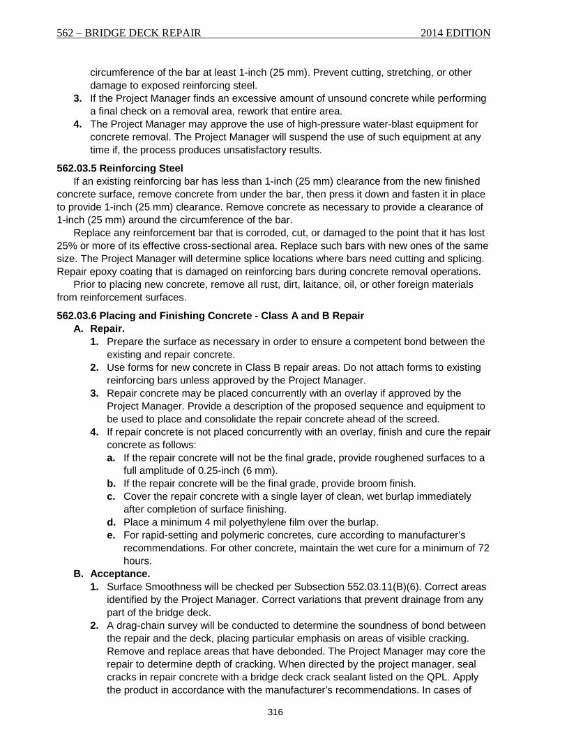
562 – BRIDGE DECK REPAIR 2014 EDITION
316
circumference of the bar at least 1-inch (25 mm). Prevent cutting, stretching, or other damage to exposed reinforcing steel.
3. If the Project Manager finds an excessive amount of unsound concrete while performing a final check on a removal area, rework that entire area.
4. The Project Manager may approve the use of high-pressure water-blast equipment for concrete removal. The Project Manager will suspend the use of such equipment at any time if, the process produces unsatisfactory results.
562.03.5 Reinforcing Steel If an existing reinforcing bar has less than 1-inch (25 mm) clearance from the new finished
concrete surface, remove concrete from under the bar, then press it down and fasten it in place to provide 1-inch (25 mm) clearance. Remove concrete as necessary to provide a clearance of 1-inch (25 mm) around the circumference of the bar.
Replace any reinforcement bar that is corroded, cut, or damaged to the point that it has lost 25% or more of its effective cross-sectional area. Replace such bars with new ones of the same size. The Project Manager will determine splice locations where bars need cutting and splicing. Repair epoxy coating that is damaged on reinforcing bars during concrete removal operations.
Prior to placing new concrete, remove all rust, dirt, laitance, oil, or other foreign materials from reinforcement surfaces.
562.03.6 Placing and Finishing Concrete - Class A and B Repair A. Repair.
1. Prepare the surface as necessary in order to ensure a competent bond between the existing and repair concrete.
2. Use forms for new concrete in Class B repair areas. Do not attach forms to existing reinforcing bars unless approved by the Project Manager.
3. Repair concrete may be placed concurrently with an overlay if approved by the Project Manager. Provide a description of the proposed sequence and equipment to be used to place and consolidate the repair concrete ahead of the screed.
4. If repair concrete is not placed concurrently with an overlay, finish and cure the repair concrete as follows: a. If the repair concrete will not be the final grade, provide roughened surfaces to a
full amplitude of 0.25-inch (6 mm). b. If the repair concrete will be the final grade, provide broom finish. c. Cover the repair concrete with a single layer of clean, wet burlap immediately
after completion of surface finishing. d. Place a minimum 4 mil polyethylene film over the burlap. e. For rapid-setting and polymeric concretes, cure according to manufacturer’s
recommendations. For other concrete, maintain the wet cure for a minimum of 72 hours.
B. Acceptance. 1. Surface Smoothness will be checked per Subsection 552.03.11(B)(6). Correct areas
identified by the Project Manager. Correct variations that prevent drainage from any part of the bridge deck.
2. A drag-chain survey will be conducted to determine the soundness of bond between the repair and the deck, placing particular emphasis on areas of visible cracking. Remove and replace areas that have debonded. The Project Manager may core the repair to determine depth of cracking. When directed by the project manager, seal cracks in repair concrete with a bridge deck crack sealant listed on the QPL. Apply the product in accordance with the manufacturer’s recommendations. In cases of
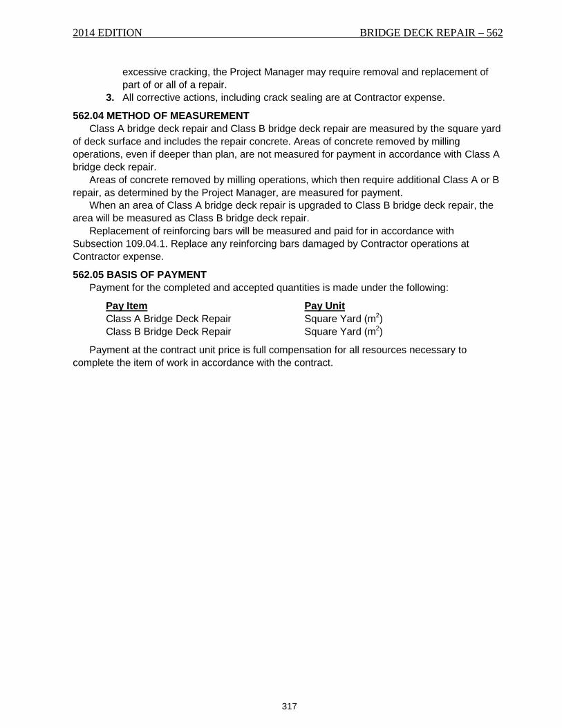
2014 EDITION BRIDGE DECK REPAIR – 562
317
excessive cracking, the Project Manager may require removal and replacement of part of or all of a repair.
3. All corrective actions, including crack sealing are at Contractor expense.
562.04 METHOD OF MEASUREMENT Class A bridge deck repair and Class B bridge deck repair are measured by the square yard
of deck surface and includes the repair concrete. Areas of concrete removed by milling operations, even if deeper than plan, are not measured for payment in accordance with Class A bridge deck repair.
Areas of concrete removed by milling operations, which then require additional Class A or B repair, as determined by the Project Manager, are measured for payment.
When an area of Class A bridge deck repair is upgraded to Class B bridge deck repair, the area will be measured as Class B bridge deck repair.
Replacement of reinforcing bars will be measured and paid for in accordance with Subsection 109.04.1. Replace any reinforcing bars damaged by Contractor operations at Contractor expense.
562.05 BASIS OF PAYMENT Payment for the completed and accepted quantities is made under the following:
Pay Item Pay Unit Class A Bridge Deck Repair Square Yard (m2) Class B Bridge Deck Repair Square Yard (m2)
Payment at the contract unit price is full compensation for all resources necessary to complete the item of work in accordance with the contract.

562 – BRIDGE DECK REPAIR 2014 EDITION
318
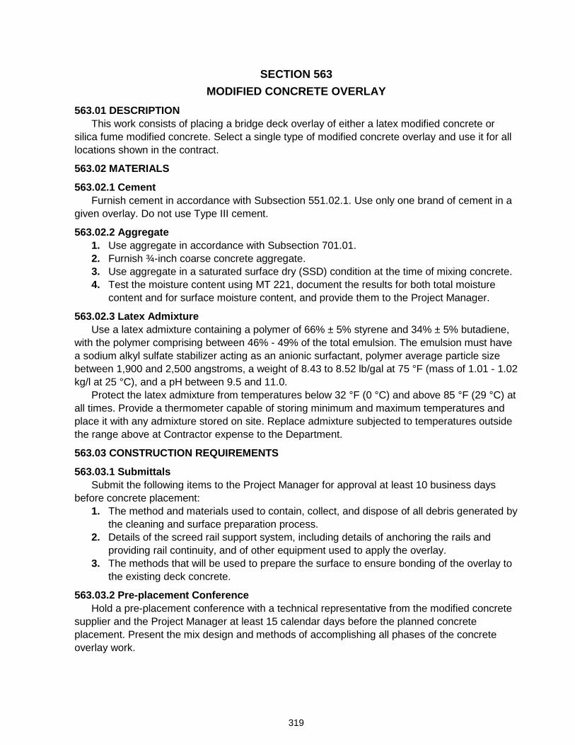
319
SECTION 563 MODIFIED CONCRETE OVERLAY
563.01 DESCRIPTION This work consists of placing a bridge deck overlay of either a latex modified concrete or
silica fume modified concrete. Select a single type of modified concrete overlay and use it for all locations shown in the contract.
563.02 MATERIALS
563.02.1 Cement Furnish cement in accordance with Subsection 551.02.1. Use only one brand of cement in a
given overlay. Do not use Type III cement.
563.02.2 Aggregate 1. Use aggregate in accordance with Subsection 701.01. 2. Furnish ¾-inch coarse concrete aggregate. 3. Use aggregate in a saturated surface dry (SSD) condition at the time of mixing concrete. 4. Test the moisture content using MT 221, document the results for both total moisture
content and for surface moisture content, and provide them to the Project Manager.
563.02.3 Latex Admixture Use a latex admixture containing a polymer of 66% ± 5% styrene and 34% ± 5% butadiene,
with the polymer comprising between 46% - 49% of the total emulsion. The emulsion must have a sodium alkyl sulfate stabilizer acting as an anionic surfactant, polymer average particle size between 1,900 and 2,500 angstroms, a weight of 8.43 to 8.52 lb/gal at 75 °F (mass of 1.01 - 1.02 kg/l at 25 °C), and a pH between 9.5 and 11.0.
Protect the latex admixture from temperatures below 32 °F (0 °C) and above 85 °F (29 °C) at all times. Provide a thermometer capable of storing minimum and maximum temperatures and place it with any admixture stored on site. Replace admixture subjected to temperatures outside the range above at Contractor expense to the Department.
563.03 CONSTRUCTION REQUIREMENTS
563.03.1 Submittals Submit the following items to the Project Manager for approval at least 10 business days
before concrete placement: 1. The method and materials used to contain, collect, and dispose of all debris generated by
the cleaning and surface preparation process. 2. Details of the screed rail support system, including details of anchoring the rails and
providing rail continuity, and of other equipment used to apply the overlay. 3. The methods that will be used to prepare the surface to ensure bonding of the overlay to
the existing deck concrete.
563.03.2 Pre-placement Conference Hold a pre-placement conference with a technical representative from the modified concrete
supplier and the Project Manager at least 15 calendar days before the planned concrete placement. Present the mix design and methods of accomplishing all phases of the concrete overlay work.
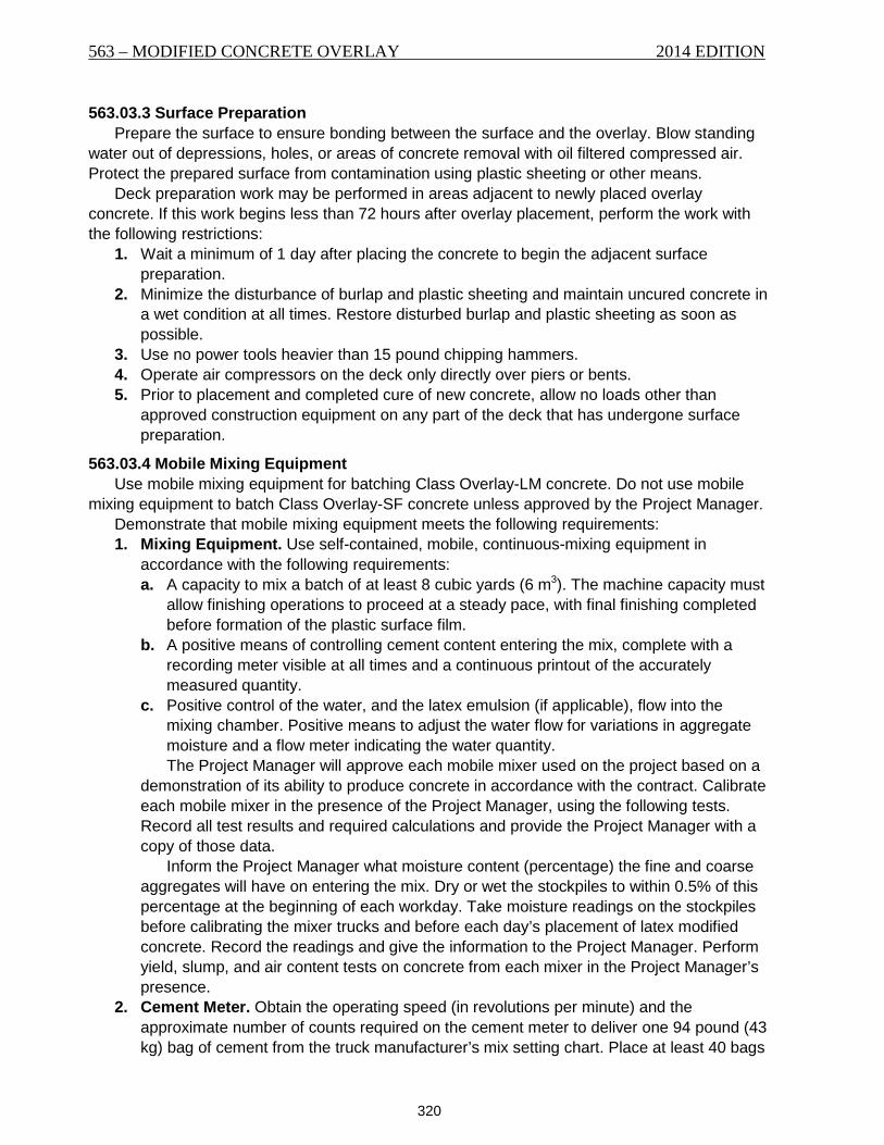
563 – MODIFIED CONCRETE OVERLAY 2014 EDITION
320
563.03.3 Surface Preparation Prepare the surface to ensure bonding between the surface and the overlay. Blow standing
water out of depressions, holes, or areas of concrete removal with oil filtered compressed air. Protect the prepared surface from contamination using plastic sheeting or other means.
Deck preparation work may be performed in areas adjacent to newly placed overlay concrete. If this work begins less than 72 hours after overlay placement, perform the work with the following restrictions:
1. Wait a minimum of 1 day after placing the concrete to begin the adjacent surface preparation.
2. Minimize the disturbance of burlap and plastic sheeting and maintain uncured concrete in a wet condition at all times. Restore disturbed burlap and plastic sheeting as soon as possible.
3. Use no power tools heavier than 15 pound chipping hammers. 4. Operate air compressors on the deck only directly over piers or bents. 5. Prior to placement and completed cure of new concrete, allow no loads other than
approved construction equipment on any part of the deck that has undergone surface preparation.
563.03.4 Mobile Mixing Equipment Use mobile mixing equipment for batching Class Overlay-LM concrete. Do not use mobile
mixing equipment to batch Class Overlay-SF concrete unless approved by the Project Manager. Demonstrate that mobile mixing equipment meets the following requirements: 1. Mixing Equipment. Use self-contained, mobile, continuous-mixing equipment in
accordance with the following requirements: a. A capacity to mix a batch of at least 8 cubic yards (6 m3). The machine capacity must
allow finishing operations to proceed at a steady pace, with final finishing completed before formation of the plastic surface film.
b. A positive means of controlling cement content entering the mix, complete with a recording meter visible at all times and a continuous printout of the accurately measured quantity.
c. Positive control of the water, and the latex emulsion (if applicable), flow into the mixing chamber. Positive means to adjust the water flow for variations in aggregate moisture and a flow meter indicating the water quantity. The Project Manager will approve each mobile mixer used on the project based on a
demonstration of its ability to produce concrete in accordance with the contract. Calibrate each mobile mixer in the presence of the Project Manager, using the following tests. Record all test results and required calculations and provide the Project Manager with a copy of those data.
Inform the Project Manager what moisture content (percentage) the fine and coarse aggregates will have on entering the mix. Dry or wet the stockpiles to within 0.5% of this percentage at the beginning of each workday. Take moisture readings on the stockpiles before calibrating the mixer trucks and before each day’s placement of latex modified concrete. Record the readings and give the information to the Project Manager. Perform yield, slump, and air content tests on concrete from each mixer in the Project Manager’s presence.
2. Cement Meter. Obtain the operating speed (in revolutions per minute) and the approximate number of counts required on the cement meter to deliver one 94 pound (43 kg) bag of cement from the truck manufacturer’s mix setting chart. Place at least 40 bags
2014 EDITION MODIFIED CONCRETE OVERLAY – 563
321
of cement in the cement bin. Place the mixer on a level surface and provide an electrical ground.
Adjust the engine throttle to obtain the specified revolutions per minute (rpm). Discharge cement until the belt has made 1 complete revolution. Stop the belt and reset the cement meter to zero. Discharge approximately 1 bag of cement into a container while timing the discharge with a stopwatch. Record the number of counts on the cement meter and determine the mass of cement discharged on the Field Calibration form included in this specification. Repeat the process of discharging 1 bag at a time for a total of 6 runs. Reset the cement meter to zero each time.
At the end of the 6 runs, total the number of cement counts, the mass of cement discharged, and the times of each of the runs, in seconds.
Perform the following calculations: a. Mass of cement per cement meter count. Divide the total mass of cement discharged
in the 6 runs by the total number of counts on the meter for the 6 runs. b. Counts per bag of cement. Divide 94 pounds (43 kg) by the mass of cement per
cement meter count. c. Cement discharge rate. Divide the total mass of cement for the 6 runs by the total of
the times for each of the 6 discharges. d. Discharge time for 1 bag. Divide 94 pounds (43 kg) by the cement discharge rate.
3. Latex Throttling Valve. Clear the latex strainer of any obstructions. Adjust the latex throttling valve to deliver 3.5 gallons (13.2 L) of latex, or 30 pounds (13.3 kg) for each bag, or 94 pounds (43 kg) of cement, using the calculation results from Subsection 563.03.4(2), where necessary.
With the unit operating at the specified rpm, discharge latex into a container for the discharge time for 1 bag calculated above and determine the weight of the latex discharged. Adjust the valve until the machine discharges 30 lbs. (13.6 kg) in the discharge time for 1 bag. Verify the accuracy of this setting by repeating the latex discharge 3 more times.
4. Water Flow Meter. Set the water flow meter to flow at the rate of 0.5 gallons (1.9 L) per minute. Collect and weigh the water discharged during 1 minute with the equipment operating at the specified rpm to verify the discharge rate. Repeat the process with the flow meter adjusted to 1.5 gallons (5.7 L) per minute.
5. Aggregate Bin Gates. Set the gate openings to provide aggregate at a rate matching the specified concrete mix proportions.
563.03.5 Concrete Placement Place concrete in accordance with Section 551. Install necessary bulkheads to the required grade and profile before placing any concrete.
Alternatively, over-pour the end of the overlay by a minimum of 6 inches (150 mm). Saw cut and remove the over-pour from the rest of the overlay.
Dispose of materials that dry out, set, or show evidence of loss of cement paste. Stop overlay placement on discovering those conditions and do the surface preparation again.
Strike off the modified concrete at a level ¼-inch (6.0 mm) above final grade. Complete hand finishing and texturing within 15 feet (4.5 m) of the finishing machine. Float and vibrate the concrete as needed to provide a tight finished surface.
Vibrate concrete more than 3 inches (75 mm) thick internally, in addition to the vibration of the surface screed. After finishing the concrete, check for surface irregularities with a 10 foot (3 m) straight edge. Correct surface areas that vary more than ⅛-inch (3 mm) in that distance.
563 – MODIFIED CONCRETE OVERLAY 2014 EDITION
322
563.03.6 Curing Cure the overlay per Subsection 551.03.7.
563.03.7 Phased Construction If the overlay is placed in phases, apply a bridge deck crack sealant to the phase line joint(s)
after the overlay has cured. Furnish a bridge deck crack sealant in accordance with Subsection 717.02.2. 563.03.8 Acceptance
1. Cast at least 1 latex modified concrete cylinder for each day’s overlay placement. Cure the cylinders with their matching deck segments. Break the cylinders at the end of the dry curing process to demonstrate the strength the overlay concrete has attained.
2. Correct areas identified by the Project Manager. Correct variations that prevent drainage from any part of the bridge deck. Do not start the process of saw cutting the transverse deck grooves until the Project Manager has approved all of the finished repair work.
3. A drag-chain survey will be conducted to determine the soundness of bond between the repair and the deck, placing particular emphasis on areas of visible cracking. Remove and replace areas that have debonded. The Project Manager may core the repair to determine depth of cracking. When directed by the Project Manager, seal cracks in repair concrete with a bridge deck crack sealant listed on the QPL. Apply the product in accordance with the manufacturer’s recommendations. In cases of excessive cracking, the Project Manager may require removal and replacement of part of or all of a repair.
All corrective actions required for acceptance are at Contractor expense.
563.04 METHOD OF MEASUREMENT Bridge deck overlay is measured by the cubic yard (m3) of modified concrete overlay placed.
Include the cost of trial batches in the unit cost of modified concrete overlay. Transverse deck grooving is measured by the square yard (m2) in accordance with
Subsection 552.04. Bridge deck crack sealant applied to phase line joint(s) is not measured for payment. Include
all costs associated with bridge deck crack sealant applied to phase line joint(s) in the modified concrete overlay item.
563.05 BASIS OF PAYMENT Payment for the completed and accepted work is made under the following:
Pay Item Pay Unit Modified - Concrete Overlay Cubic Yard (m3)
Payment at the contract unit price is full compensation for all resources necessary to complete the item of work in accordance with the contract.
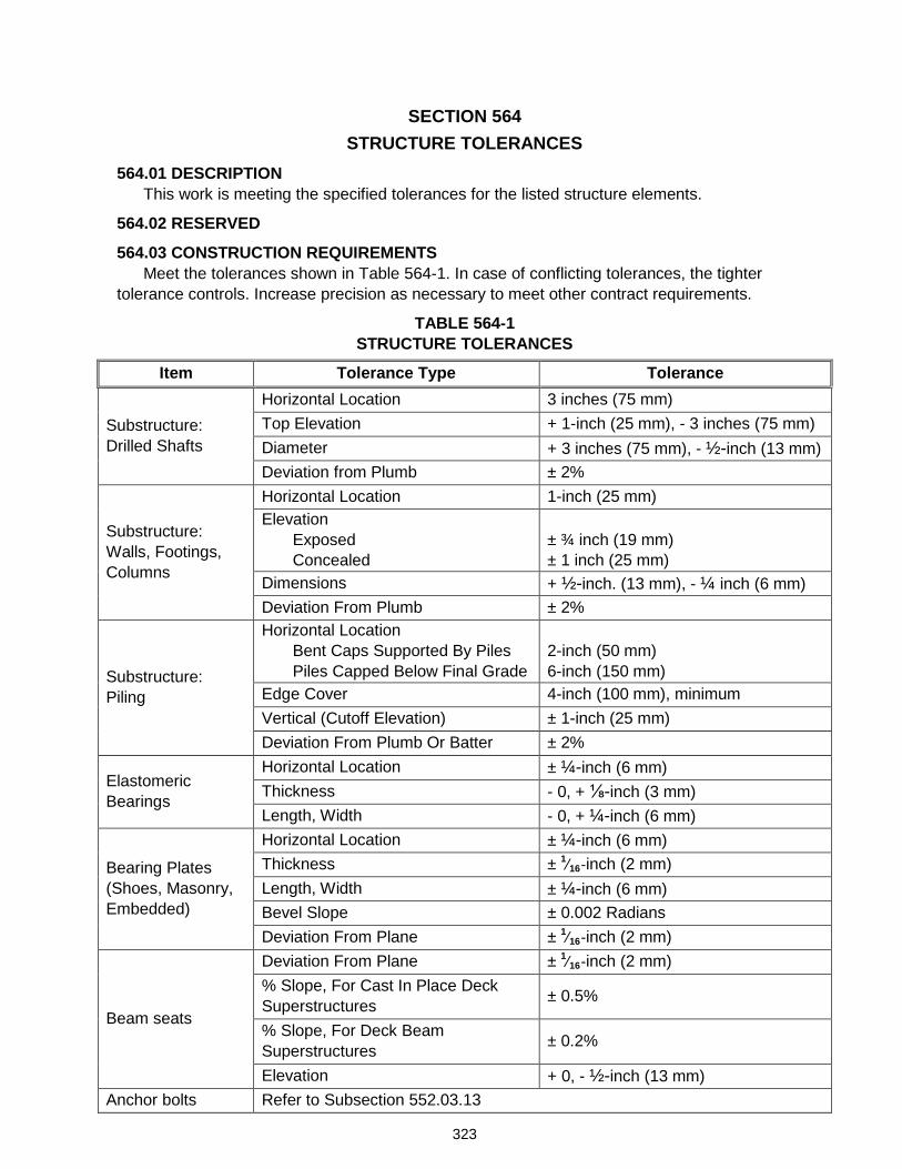
323
SECTION 564 STRUCTURE TOLERANCES
564.01 DESCRIPTION This work is meeting the specified tolerances for the listed structure elements.
564.02 RESERVED
564.03 CONSTRUCTION REQUIREMENTS Meet the tolerances shown in Table 564-1. In case of conflicting tolerances, the tighter
tolerance controls. Increase precision as necessary to meet other contract requirements.
TABLE 564-1 STRUCTURE TOLERANCES
Item Tolerance Type Tolerance
Substructure: Drilled Shafts
Horizontal Location 3 inches (75 mm) Top Elevation + 1-inch (25 mm), - 3 inches (75 mm) Diameter + 3 inches (75 mm), - ½-inch (13 mm) Deviation from Plumb ± 2%
Substructure: Walls, Footings, Columns
Horizontal Location 1-inch (25 mm) Elevation
Exposed Concealed
± ¾ inch (19 mm) ± 1 inch (25 mm)
Dimensions + ½-inch. (13 mm), - ¼ inch (6 mm) Deviation From Plumb ± 2%
Substructure: Piling
Horizontal Location Bent Caps Supported By Piles Piles Capped Below Final Grade
2-inch (50 mm) 6-inch (150 mm)
Edge Cover 4-inch (100 mm), minimum Vertical (Cutoff Elevation) ± 1-inch (25 mm) Deviation From Plumb Or Batter ± 2%
Elastomeric Bearings
Horizontal Location ± ¼-inch (6 mm) Thickness - 0, + ⅛-inch (3 mm) Length, Width - 0, + ¼-inch (6 mm)
Bearing Plates (Shoes, Masonry, Embedded)
Horizontal Location ± ¼-inch (6 mm) Thickness ± 1⁄16-inch (2 mm) Length, Width ± ¼-inch (6 mm) Bevel Slope ± 0.002 Radians Deviation From Plane ± 1⁄16-inch (2 mm)
Beam seats
Deviation From Plane ± 1⁄16-inch (2 mm) % Slope, For Cast In Place Deck Superstructures ± 0.5%
% Slope, For Deck Beam Superstructures ± 0.2%
Elevation + 0, - ½-inch (13 mm) Anchor bolts Refer to Subsection 552.03.13
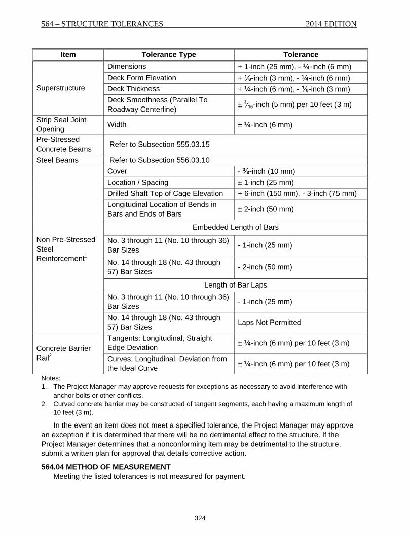
564 – STRUCTURE TOLERANCES 2014 EDITION
324
Item Tolerance Type Tolerance
Superstructure
Dimensions + 1-inch (25 mm), - ¼-inch (6 mm) Deck Form Elevation + ⅛-inch (3 mm), - ¼-inch (6 mm) Deck Thickness + ¼-inch (6 mm), - ⅛-inch (3 mm) Deck Smoothness (Parallel To Roadway Centerline) ± 3⁄16-inch (5 mm) per 10 feet (3 m)
Strip Seal Joint Opening Width ± ¼-inch (6 mm)
Pre-Stressed Concrete Beams Refer to Subsection 555.03.15
Steel Beams Refer to Subsection 556.03.10
Non Pre-Stressed Steel Reinforcement1
Cover - ⅜-inch (10 mm) Location / Spacing ± 1-inch (25 mm) Drilled Shaft Top of Cage Elevation + 6-inch (150 mm), - 3-inch (75 mm) Longitudinal Location of Bends in Bars and Ends of Bars ± 2-inch (50 mm)
Embedded Length of Bars
No. 3 through 11 (No. 10 through 36) Bar Sizes - 1-inch (25 mm)
No. 14 through 18 (No. 43 through 57) Bar Sizes - 2-inch (50 mm)
Length of Bar Laps No. 3 through 11 (No. 10 through 36) Bar Sizes - 1-inch (25 mm)
No. 14 through 18 (No. 43 through 57) Bar Sizes Laps Not Permitted
Concrete Barrier Rail2
Tangents: Longitudinal, Straight Edge Deviation ± ¼-inch (6 mm) per 10 feet (3 m)
Curves: Longitudinal, Deviation from the Ideal Curve ± ¼-inch (6 mm) per 10 feet (3 m)
Notes: 1. The Project Manager may approve requests for exceptions as necessary to avoid interference with
anchor bolts or other conflicts. 2. Curved concrete barrier may be constructed of tangent segments, each having a maximum length of
10 feet (3 m).
In the event an item does not meet a specified tolerance, the Project Manager may approve an exception if it is determined that there will be no detrimental effect to the structure. If the Project Manager determines that a nonconforming item may be detrimental to the structure, submit a written plan for approval that details corrective action.
564.04 METHOD OF MEASUREMENT Meeting the listed tolerances is not measured for payment.

2014 EDITION STRUCTURE TOLERANCES – 564
325
564.05 BASIS OF PAYMENT Meeting listed tolerances is incidental to the work. Include all costs associated with meeting
the listed tolerances in the bid item that includes the structure item listed.

564 – STRUCTURE TOLERANCES 2014 EDITION
326
327
SECTION 565 BEARING DEVICES
565.01 DESCRIPTION This work is the furnishing and placing of bearing devices.
565.02 MATERIALS Furnish material in accordance with the following subsection requirements: A. Elastomeric Devices
1. Elastomeric Bearing Devices ............................. 711.14 2. Steel Laminates ................................................. 711.14 3. Polytetrafluoroethylene (PTFE) ......................... 711.20 4. Stainless Steel Sheets ....................................... 711.20
B. Fiber Reinforced Pads .......................................... 711.16 C. Steel Bearing Plates .............................................. 711.02
565.03 CONSTRUCTION REQUIREMENTS
565.03.1 General Submit shop drawings as directed by the contract. Do not fabricate bearings prior to
receiving approved drawings. A. Packaging. Package and protect the bearings from damage and prevent contamination
of the contact surfaces of the sliding elements during handling, transporting, and storage. Replace any bearing damaged by handling, transporting or storage at no cost to the State.
B. Installation of Elastomeric Devices. Place bearings on a level surface. Correct any misalignment of the support to form a level surface. The instantaneous temperatures of the sole plates must not exceed 300 °F (149 °C) when field welding the sole plate to the steel girder or base plates embedded in concrete beams. Replace any bearing damaged during installation at Contractor expense.
565.03.2 Bearing and Anchorage Place masonry bearing plates on bearing areas that meet the contract requirements. Install
bearing plates level to provide full bearing on the masonry. Place masonry bearing plates on fiber reinforced pads in accordance with Subsection 711.16
that project a minimum ½-inch (13 mm) on all sides of the bearing plate. Finish the bearing area to a level plane. The surface must not vary by more than 1⁄16-inch
(2 mm) from a straightedge placed in any direction across the area. Extend the bearing area at least 1-inch (25 mm) beyond the bearing contact area. The finished elevation of the bearing surface must not vary by more than ⅛-inch (3 mm) from the specified beam-seat elevation unless otherwise approved by the Project Manager.
A. Steel Structures. Make allowances for bottom chord elongation due to dead load when setting shoes or bearing plates for steel truss spans.
Install bridge rocker shoes to be vertical under full dead load at 32 °F (0 °C). Raise spans and make adjustments if the rockers are not correctly positioned with the final dead load on spans.
B. Steel Shims. Use steel shims when necessary to bring the masonry plates up to grade. Use shims of the same size as the masonry plate and a minimum ¼-inch (6 mm) thick.
565.03.3 PTFE Bearings Furnish PTFE bearings composed of pure, unreinforced, polytetrafluoroethylene fluorocarbon
resin sheets bonded to the elastomeric pads. Weld stainless steel sheets to the sole plates as
565 – BEARING DEVICES 2014 EDITION
328
shown in the contract. Use only new materials for the manufacture of the bearings with no reclaimed material incorporated into a finished bearing. The dimensions of the finished bearings must meet the tolerances as specified in Section 564.
Unless otherwise approved by the Project Manager, furnish bearing assemblies, including the sole plates, as a complete unit from one manufacturing source.
Polish stainless steel in contact with the PTFE surface to a mirror bright finish as specified in ASTM A480, finish No. 8.
Edge weld the stainless steel sheets to the sole plates using E308L or E309L electrodes as specified in ASW A5.4 and Section 624, sized for the stainless steel sheet. Any portion of the weld that extends above the surface of the finish of the stainless steel sheet must be ground to the surface of the sheet. Repair any imperfections in the finish of the stainless steel sheet caused by welding or grinding prior to shipment.
Vulcanize bond steel backing plates and masonry plates, if any, to the elastomeric pad.
565.04 METHOD OF MEASUREMENT Elastomeric devices are measured by each device required for 1 beam seat. Fiber reinforced pads are not measured for payment. Steel bearing plates are included in the cost of concrete beams, but are measured in
accordance with Subsection 556.04 if steel girders are supplied.
565.05 BASIS OF PAYMENT Payment for the completed and accepted quantities is made under the following:
Pay Item Pay Unit Elastomeric Bearing Devices Each Elastomeric Bearing Devices-PTFE Each
Payment at the contract unit price is full compensation for all resources necessary to complete the item of work in accordance with the contract.