Embed Size (px)
Citation preview
1
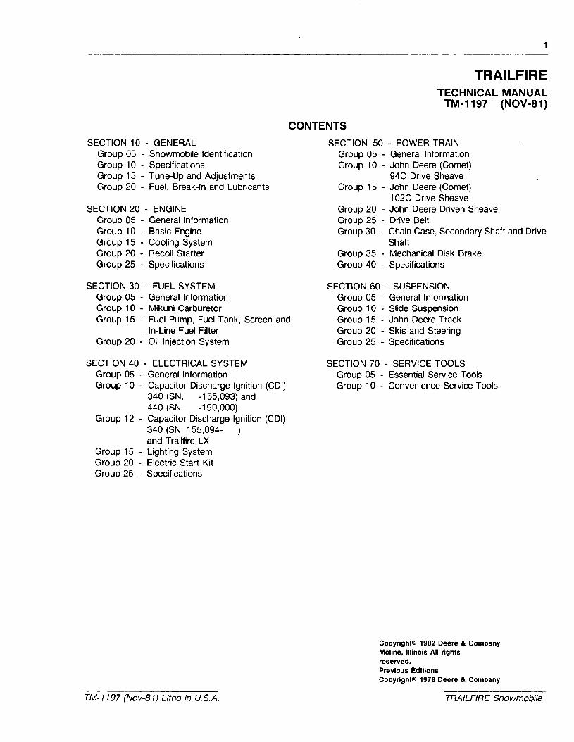
TRAILFIRETECHNICAL MANUAL
TM-1197 (NOV-81)
SECTION 10 - GENERALGroup 05 - Snowmobile IdentificationGroup 10 - SpecificationsGroup 15 - Tune-Up and AdjustmentsGroup 20 - Fuel, Break-In and Lubricants
SECTION 20 - ENGINEGroup 05 - General InformationGroup 10 - Basic EngineGroup 15 - Cooling SystemGroup 20 - Recoil StarterGroup 25 - Specifications
CONTENTS
SECTION 50 - POWER TRAINGroup 05 - General InformationGroup 1°-John Deere (Comet)
94C Drive SheaveGroup 15 - John Deere (Comet)
102C Drive SheaveGroup 20 - John Deere Driven SheaveGroup 25 - Drive BeltGroup 30 - Chain Case, Secondary Shaft and Drive
ShaftGroup 35 - Mechanical Disk BrakeGroup 40 - Specifications
SECTION 30 - FUEL SYSTEMGroup 05 - General InformationGroup 10 - Mikuni CarburetorGroup 15 - Fuel Pump, Fuel Tank, Screen and
In-Line Fuel FilterGroup 20 -- Oil Injection System
SECTION 40 - ELECTRICAL SYSTEMGroup 05 - General InformationGroup 10 - Capacitor Discharge Ignition (CDI)
340 (SN. -155,093) and440 (SN. -190,000)
Group 12 - Capacitor Discharge Ignition (COl)340 (SN. 155,094- )and Trailfire LX
Group 15 - Lighting SystemGroup 20 - Electric Start KitGroup 25 - Specifications
TM-1197 (Nov-81) Litho in U.S.A.
SECTION 60 - SUSPENSIONGroup 05 - General InformationGroup 1°-Slide SuspensionGroup 15 - John Deere TrackGroup 20 - Skis and SteeringGroup 25 - Specifications
SECTION 70 - SERVICE TOOLSGroup 05 - Essential Service ToolsGroup 1°-Convenience Service Tools
Copyright© 1982 Deere & CompanyMoline, Illinois All rightsreserved.Previous EditionsCopyright© 1978 Deere & Company
TRAILFIRE Snowmobile
Section 10GENERAL SNOWMOBILE IDENTIFICATION
CONTENTS
Page
GROUP 5 - SNOWMOBILE IDENTIFICATION
Snowmobile Serial Number 10-05-1Engine Serial Number 10-05-1Vintage Information 10-05-1
GROUP 10 - SPECIFICATIONS
Snowmobile Specifications . . . . . . . . . . . .10-10-1Engine Specifications 10-10-2
Page
GROUP 15 - TUNE-UP ANDADJUSTMENT
Tune-Up Guide 10-15-1Adjustments 10-15-1Spark Plug 10-15-1
GROUP 20 - FUEL, BREAK-IN ANDLUBRICANTS
Break-In Period 10-20-1Fuel. 10-20-1Lubricants 10-20-1
1197/100QA/050681
Litho in U.S.A. 10-00-1 TM-1197 (Nov-81)

Litho in U.S.A.
General Snowmobile Identification
10-00-2 TM-11.97 (Nov..81)
Group 5
SNOWMOBILE IDENTIFICATION
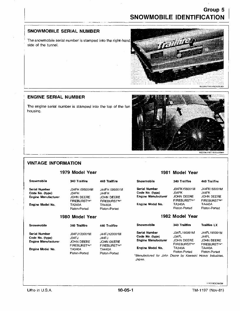
SNOWMOBILE SERIAL NUMBER
The snowmobile serial number is stamped into the nnnT-nr:lnn
side of the tunnel.
M23295/1197/1005A/050681
ENGINE SERIAL NUMBER
The engine serial number is stamped into the top of the fanhousing.
M23296/1197/1005B/050681
1981 Model Year
Snowmobile
Serial NumberCode No. (type)Engine Manufacturer
Engine Model No.
340 Trailfire
J34FK155001MJ34FKJOHN DEEREFIREBURSTTM*TA340APiston-Ported
440 Trailfire
J44FK155001MJ44FKJOHN DEEREFIREBURSTTM*TA440APiston-Ported
Snowmobile
1982 Model Year
340 Trailfire Trailfire LX
Litho in U.S.A. 101Q05-1
Serial Number J34FL 190001M J44FL190001MCode No. (type) J34FL J44FLEngine Manufacturer JOHN DEERE JOHN DEERE
FIREBURSTTM* FIREBURSTTM*Engine Model No. TA340A TA440A
Piston-Ported Piston-Ported*Manufactured for John Deere by Kawaski Heavy Industries,Japan.
1197/1005C/060581
TM-1197 (Nov-81)

Litho in U.S.A.
Snowmobile Identification
10-05-2 TM-1197 (Nov-81)
Group 10
SPECIFICATIONS
SNOWMOBILE SPECIFICATIONS
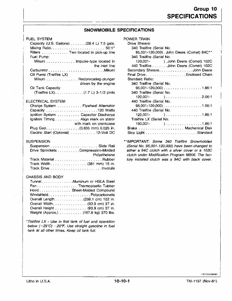
FUEL SYSTEMCapacity (U.S. Gallons) (28.4 L) 7.5 gals.Mixing Ratio 50:1 *Filters Two located in pick-up lineFuel Pump:
Mikuni Impulse-type located inthe inlet line
Carburetor . . . . . . . . . . . . . . . . . . . . . . . . .MikuniOil Pump (Trailfire LX)
Mikuni . . . . . . . . . . . . . . Reciprocating-plungerdriven by the engine
Oil Tank Capacity(Trailfire LX) (1.7 L) 3-1/2 pints
ELECTRICAL SYSTEMCharge System . . . . . . . . . . . Flywheel AlternatorCapacity 120 WattsIgnition System . . . . . . . . . . Capacitor DischargeIgnition Timing Align mark on stator
.with mark on crankcasePlug Gap (0.635 mm) 0.025 in.Electric Start (Optional) 12-Volt DC
SUSPENSIONSuspension . . . . . . . . . . . . . . . . . . . . . Slide RailDrive Sprockets . . . . . . . . . .Compression-Molded
PolyetheleneTrack Material RubberTrack Width (381 mm) 15 in.Track Drive Involute
CHASSIS AND BODYTunnel Aluminum or HSLA SteelPan Thermoplastic TubberHood. . . . . . . . . . . . . . Sheet-Molded CompoundWindshield. . . . . . . . . . . . . . . . . . . PolycarbonateOverall Length (259.1 cm) 102 in,Overall Width. . . . . . . . . . . . . . . (93.9 cm) 37 in.Overall Height . . . . . . . . . . . . . . (93.9 em) 37 in.Weight (Approx.) (167.8 kg) 370 Ibs.
*Trailfire LX - Use in first tank of fuel and operationbelow (-29°C) -20°F. Use straight gasoline in fueltank at all other times. Keep oil tank full.
POWER TRAINDrive Sheave:
340 Trailfire (Serial No.95,001-120,000) . John Deere (Comet) 94C**
340 Tralltire (Serial No.120,001- ) .John Deere (Comet) 102C
440 Trailfire John Deere (Comet) 102CSecondary Sheave. . . . . . . . . . . . . . .John DeereFinal Drive Enclosed ChainStandard Ratio:
340 Trailfire (Serial No.95,001-120,000) 1.86:1
340 Trailfire (Serial No.120,001- ) 2.06:1
440 Trailfire (Serial No.95,001-120,000) 1.56:1
440 Trailfire (Serial No.120,001- ) . . . . . . . . . . . . . . . . 1.86:1
Trailfire LX (Serial No.190,001- ) 1.86:1
Brake . . . . . . . . . . . . . . . . . . . . Mechanical DiskStop Light . . . . . . . . . . . . . . . . . . . . . . .Standard
**/MPORTANT: Some 340 Trailfire Snowmobiles(Serial No. 95,001-120,000) have been changed toeither a 94C clutch with a silver cover or a 102Cclutch under Modification Program M906. The factory installed clutch was a 94C with black cover.
1197/1010A/060581
Litho in U.S.A. 10-10-1 TM-1197 (Nov-81)
Specifications
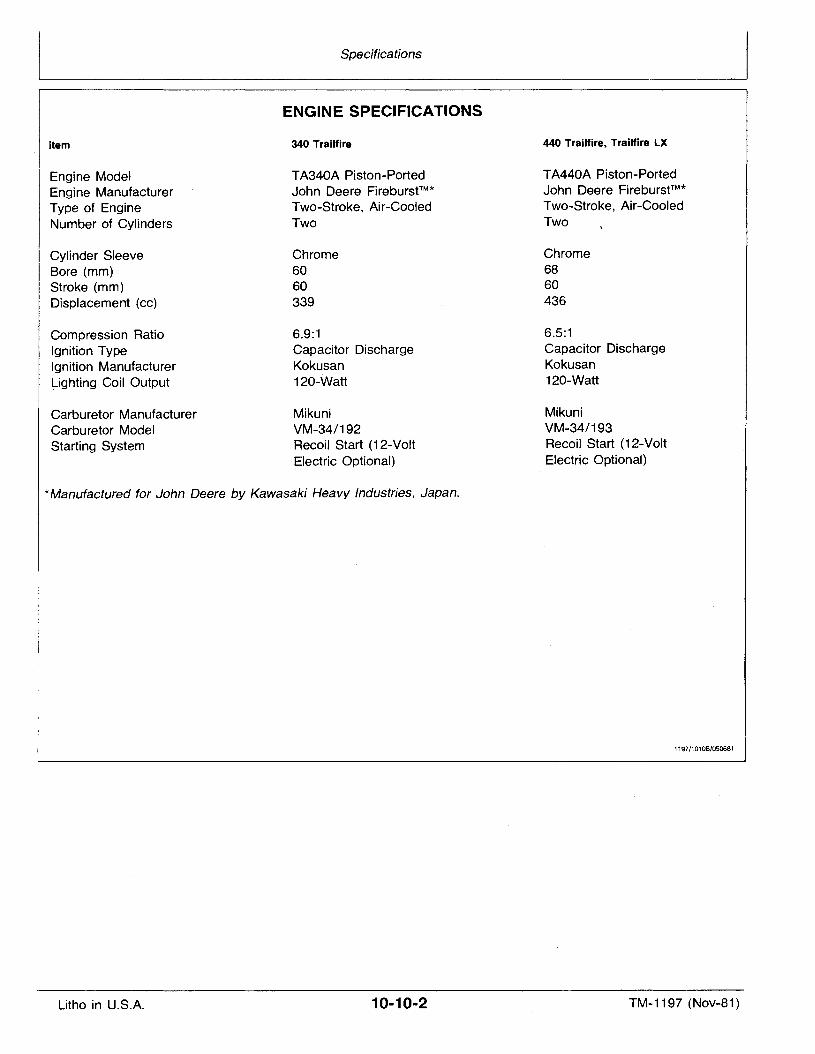
ENGINE· SPECIFICATIONS
Item
Engine ModelEngine ManufacturerType of EngineNumber of Cylinders
Cylinder SleeveBore (mm)Stroke (mm)Displacement (cc)
Compression RatioIgnition TypeIgnition Manufacturer~ighting Coil Output
Carburetor ManufacturerCarburetor ModelStarting System
340 Trailfire
TA340A Piston-PortedJohn Deere Flreburst?"Two-Stroke, Air-CooledTwo
Chrome6060339
6.9:1Capacitor DischargeKokusan120-Watt
MikuniVM-34/192Recoil Start (12-VoltElectric Optional)
440 Trailfire, Trailfire LX
TA440A Piston-PortedJohn Deere Flreburst?"Two-Stroke, Air-CooledTwo
Chrome6860436
6.5:1Capacitor DischargeKokusan120-Watt
MikuniVM-34/193Recoil Start (12-VoltElectric Optional)
*Manufactured for John Deere by Kawasaki Heavy Industries, Japan.
1197/10108/050681
Litho in U.S.A. 10-10-2 TM-1197 (Nov-81)
Group 15
TUNE-UP AND ADJUSTMENTSI10..-- _
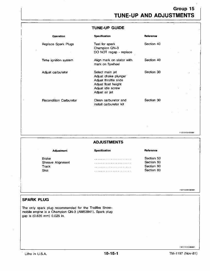
TUNE-UP.GUIDE
Operation
Replace Spark Plugs
Time ignition system
Adjust carburetor
Recondi"tion Carburetor
Adjustment
BrakeSheave AlignmentTrackSkis
SPARK PLUG
Specification
Test for sparkChampion QN-3DO NOT regap - replace
Align mark on stator withmark on flywheel
Select main jetAdjust choke plungerAdjust throttle slideAdjust float heightAdjust idle' screwAdjust air jet
Clean carburetor andinstall carburetor kit
ADJUSTMENTS
Specification
Reference
Section 40
Section 40
Section 30
Section 30
Reference
Section 50Section 50Section 60Section 60
1197/1015A/050681
1197/10158/080681
The only spark plug recommended for the Trailfire Snowmobile engine is a Champion QN-3 (AM53941). Spark pluggap is (0.635 mm) 0.025 in.
1197/1015C/080681
Litho' in U.S.A. 10-15-1 TM-1197 (Nov-81)

Litho in U.S.A.
Tune-Up and Adjustments
10-15-2 TM-1197 (Nov-81)
Group 20
.FUEL, BREAK-IN AND LUBRICANTS
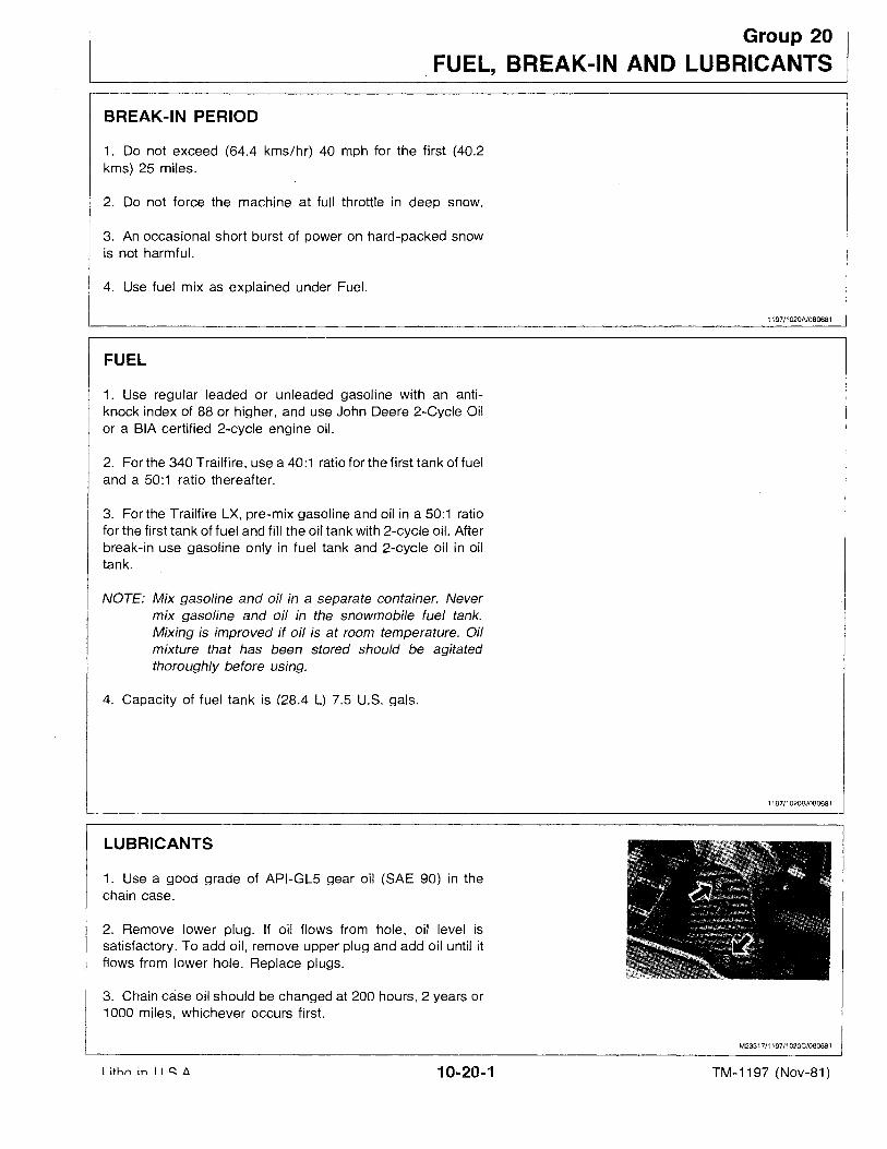
BREAK-IN PERIOD
1. Do not exceed (64.4 kms/hr) 40 mph for the first (40.2kms) 25 miles.
2. Do not force the machine at full throttle in deep snow.
3. An occasional short burst of power on hard-packed snowis not harmful.
4. Use fuel mix as explained under Fuel.
1197/1020A/080681
FUEL
1. Use regular leaded or unleaded gasoline with an antiknock index of 88 or higher, and use John Deere 2-Cycle Oilor a BIA certified 2-cycle engine oil.
2. For the 340 Trailfire, use a 40:1 ratio for the first tank of fueland a 50:1 ratio thereafter.
3. For the Trailfire LX, pre-mix gasoline and oil in a 50:1 ratiofor the first tank of fuel and fill the oil tank with 2-cycle oil. Afterbreak-in use gasoline only in fuel tank and 2-cycle oil in oiltank.
NOTE: Mix gasoline and oil in a separate container. Nevermix gasoline and oil in the snowmobile fuel tank.Mixing is improved if oil is at room temperature. Oilmixture that has been stored should be agitatedthoroughly before using.
4. Capacity of fuel tank is (28.4 L) 7.5 U.S. gals.
1197/10208/080681
LUBRICANTS
1. Use a good grade of API-GL5 gear oil (SAE 90) in thechain case.
2. Remove lower plug. If oil flows from hole, oil level issatisfactory. To add oil, remove upper plug and add oil until itflows from lower hole. Replace plugs.
3. Chain case oil should be changed at 200 hours, 2 years or1000 miles, whichever occurs first.
M23317/1197/1020C/080681
I ithn in I I ~ A 10-20-1 TM-1197 (Nov-81)

Litho in U.S.A.
Fuel, Break-In and Lubricants
10-20-2 TM-1197 (Nov-81)
Section 20ENGINE
CONTENTS
Page
GROUP 5 - GENERAL INFORMATIONPower Stroke 20-05-1Exhaust Stroke 20-05-1Fuel Transfer Stroke 20-05-1Compression and Intake Stroke 20-05-1Diagnose Malfunctions 20-05-2Engine Spark Test 20-05-3Engine Compression Test. 20-05-3
GROUP 10 - BASIC ENGINERemove Engine. . . . . . . . . . . . . . . . . . . .20-10-1Remove Engine Exterior Components 20-10-2Remove Fan Housing 20-10-2Remove Flywheel. . . . . . . . . . . . . . . . . . .20-10-3Remove Stator 20-10-3Remove Manifolds . . . . . . . . . . . . . . . . . .20-10-4Check Crankshaft Runout 20-10-4Remove Cylinders and Heads 20-10-4Remove Pistons 20-10-4Separate Crankcase Halves 20-10-5Remove Crankshaft 20-10-5Inspect Cylinder Heads 20-10-6Inspect Cylinders 20-10-6Inspect Pistons and Rings 20-10-7Inspect Crankshaft 20-10-8Inspect Crankcase 20-10-9Replace Outer Crankshaft Bearings 20-10-9
Page
GROUP 10 - BASIC ENGINE-ContinuedInstall Crankshaft Seals . . . . . . . . . . . . .20-10-10Install Crankshaft. . . . . . . . . . . . . . . . . .20-10-10Install Lower Crankcase Half 20-10-11Install Pistons 20-10-11Install Cylinders and Heads 20-10-11Install Stator and Time Ignition 20-10-12Install Flywheel 20-10-12Install Flywheel Housing 20-10-12Install Exterior Components 20-10-14Pressure Test Engine 20-10-15Install Engine 20-10-15
GROUP 15 - COOLING SYSTEMCheck Fan Belt Tension 20-15-1Adjust Fan Belt Tension 20-15-1Replace Fan Belt ' 20-15-2Replace Fan or Fan Bearings 20-15-3
GROUP 20 - RECOIL STARTERRemove Starter 20-20-1Disassemble Starter 20-20-1Assemble Starter 20-20-3Install Starter 20-20-6
GROUP 25 - SPECIFICATIONS340 Engine Specifications. . . . . . . . . . . . .20-25-1440 and Trailfire LX Engine Specifications 20-25-1Spark Plug Specification 20-25-1Torque Specifications 20-25-2
1197J2000Al100681
Litho in U.S.A. 20-00-1 TM-1197 (Nov-81)

Litho in U.S.A.
Engine
20-00-2 TM-1197 (Nov-81)
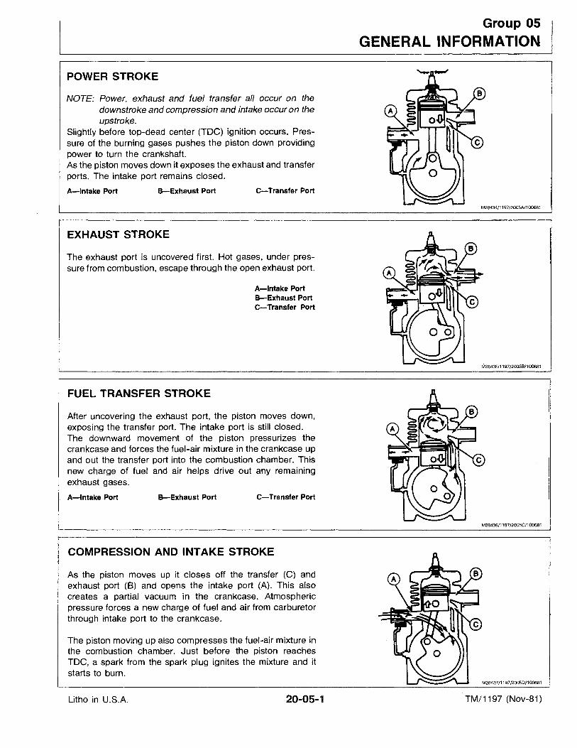
POWER STROKE
NOTE: Power, exhaust and fuel transfer all occur on thedownstroke and compression and intake occur on theupstroke.
Slightly before top-dead center (TOG) ignition occurs. Pressure of the burning gases pushes the piston down providingpower to turn the crankshaft.As the piston moves down it exposes the exhaust and transferports. The intake port remains closed.
A-Intake Port B-Exhaust Port C-Transfer Port
Group 05
GENERAL INFORMATION
M28434/1197/2005A/100681
EXHAUST STROKE
The exhaust port is uncovered first. Hot gases, under pressure from combustion, escape through the open exhaust port.
A-Intake PortB-Exhaust Porte-Transfer Port
M28435/1197/2005B/100681
FUEL TRANSFER STROKE
After uncovering the exhaust port, the piston moves down,exposing the transfer port. The intake port is still closed.The downward movement of the piston pressurizes thecrankcase and forces the fuel-air mixture in the crankcase upand out the transfer port into the combustion chamber. Thisnew charge of fuel and air helps drive out any remainingexhaust gases.
A-Intake Port B-Exhaust Port C-Transfer Port
M28436/1197/2005C/100681
COMPRESSION AND INTAKE STROKE
As the piston moves up it closes off the transfer (C) andexhaust port (8) and opens the intake port (A). This alsocreates a partial vacuum in the crankcase. Atmosphericpressure forces a new charge of fuel and air from carburetorthrough intake port to the crankcase.
The piston moving up also compresses the fuel-air mixture inthe combustion chamber. Just before the piston reachesTOG, a spark from the spark plug ignites the mixture and itstarts to burn.
M28437/1197/2005D/100681
Litho in U.S.A. 20-05-1 TM/1197 (Nov-81)
General Information
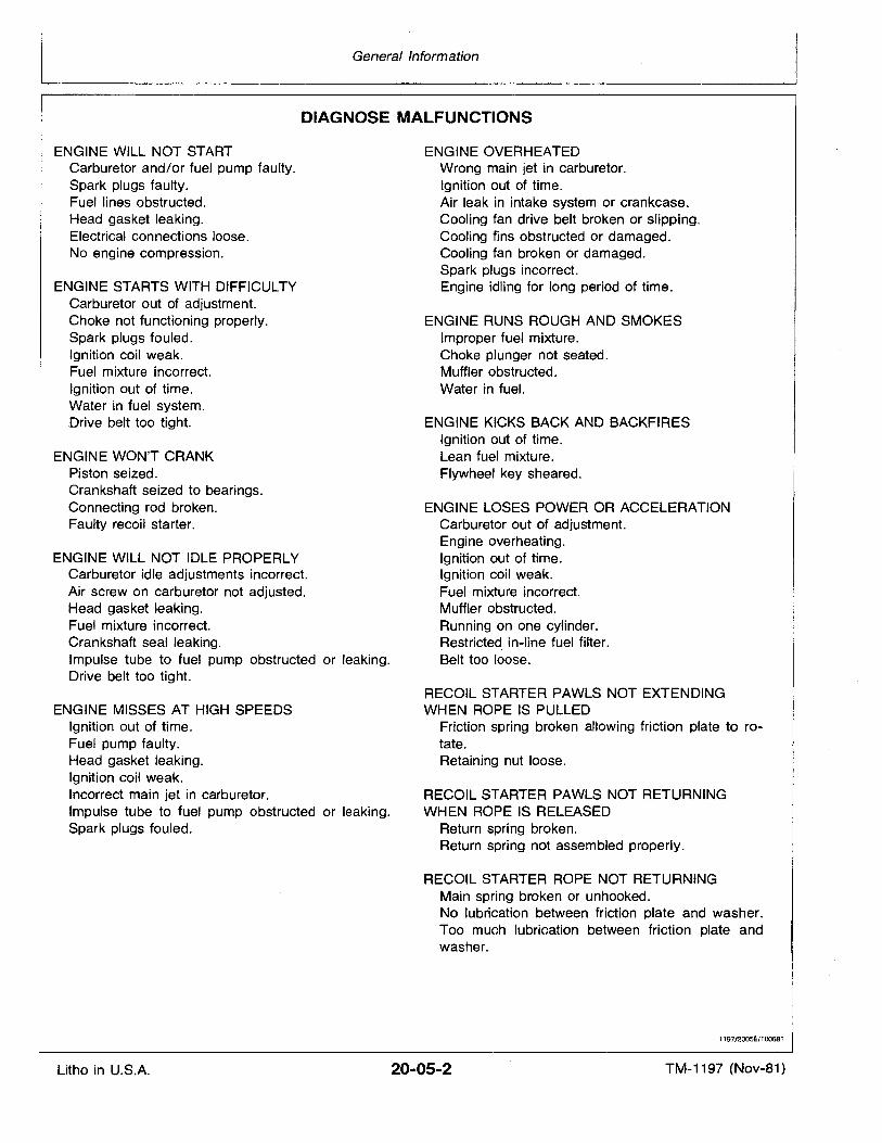
DIAGNOSE MALFUNCTIONS
ENGINE WILL NOT STARTCarburetor and/or fuel pump faulty.Spark plugs faulty.Fuel lines obstructed.Head gasket leaking.Electrical connections loose.No engine compression.
ENGINE STARTS WITH DtFFICULTYCarburetor out of adjustment.Choke not functioning properly.Spark plugs fouled.Ignition coil weak.Fuel mixture incorrect.Ignition out of time.Water in fuel system..Drive belt too tight.
ENGINE WON'T CRANKPiston seized.Crankshaft seized to bearings.Connecting rod broken.Faulty recoil starter.
ENGINE WILL NOT IDLE PROPERLYCarburetor idle adjustments incorrect.Air screw on carburetor not adjusted.Head gasket leaking.Fuel mixture incorrect.Crankshaft seal leaking.Impulse tube to fuel pump obstructed or leaking.Drive belt too tight.
ENGINE MISSES AT HIGH SPEEDSIgnition out of time.Fuel pump faulty.Head gasket leaking.Ignition coil weak.Incorrect main jet in carburetor.Impulse tube to fuel pump obstructed or leaking.Spark plugs fouled.
ENGINE OVERHEATEDWrong main jet in carburetor.Ignition out of time.Air leak in intake system or crankcase.Cooling fan drive belt broken or slipping.Cooling fins obstructed or damaged.Cooling fan broken or damaged.Spark plugs incorrect.Engine idling for long period of time.
ENGINE RUNS ROUGH AND SMOKESImproper fuel mixture.Choke plunger not seated.Muffler obstructed.Water in fuel.
ENGINE KICKS BACK AND BACKFIRESIgnition out of time.Lean fuel mixture.Flywheel key sheared.
ENGINE LOSES POWER OR ACCELERATIONCarburetor out of adjustment.Engine overheating.Ignition out of time.Ignition coil weak.Fuel mixture incorrect.Muffler obstructed.Running on one cylinder.Restricted in-line fuel filter.Belt too loose.
RECOIL STARTER PAWLS NOT EXTENDINGWHEN ROPE IS PULLED
Friction spring broken allowing friction plate to rotate.Retaining nut loose.
RECOIL STARTER PAWLS NOT RETURNINGWHEN ROPE IS RELEASED
Return spring broken.Return spring not assembled properly.
RECOIL STARTER ROPE NOT RETURNINGMain spring broken or unhooked.No lubrication between friction plate and washer.Too much lubrication between friction plate andwasher.
1197J200SE/100681
Litho in U.S.A. 20-05-2 TM-1197 (Nov-81)
General Information
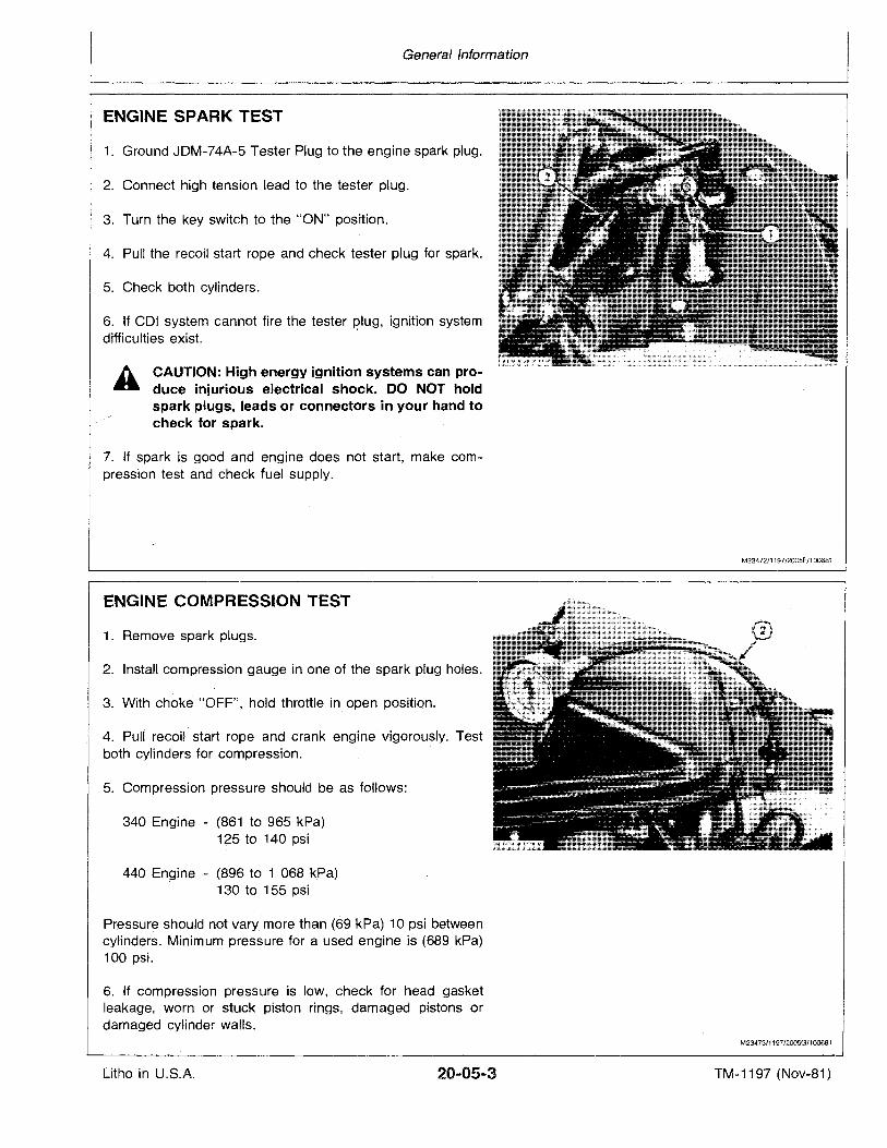
5. Check both cylinders.
1. Ground JDM-74A-5 Tester Plug to the engine spark plug.
4. Pull the recoil start rope and check tester plug for spark.
CAUTION: High energy ignition systems can produce injurious electrical shock. DO NOT holdspark plugs, leads or connectors in your hand tocheck for spark.
A
2. Connect high tension lead to the tester plug.
6. If COl system ·cannot fire the tester plug, ignition systemdifficulties exist. I
3. Turn the key switch to the "ON" position.
ENGINE SPARK TEST
7. If spark is good and engine does not start, make compression test and check fuel supply.
M23472/1197/2005F/100681
ENGINE COMPRESSION TEST
1. Remove spark plugs.
2. Install compression gauge in one of the spark plug holes.
3. With choke "OFF", hold throttle in. open position.
4. Puli recoil start rope and crank engine vigorously. Testboth cylinders for compression.
5. Compression ·pressure should be as follows:
340 Engine - (861 to 965 kPa)125 to 140 psi
440 En~ine- (896 to 1 068 kPa)130 to 155 psi
Pressure should not vary more than (69 kPa) 10 psi betweencylinders. Minimum pressure for a used engine is (689 kPa)100 psi.
6. If compression pressure is low, check for head gasketleakage, worn or stuck piston rings, damaged pistons ordamaged cylinder walls.
M23473/1197/2005G/1Q0681
Litho in U.S.A. 20-05-3 TM-1197 (Nov-81)

Litho in U.S.A.
General Information
20-05-4 TM-1197 (Nov-81)
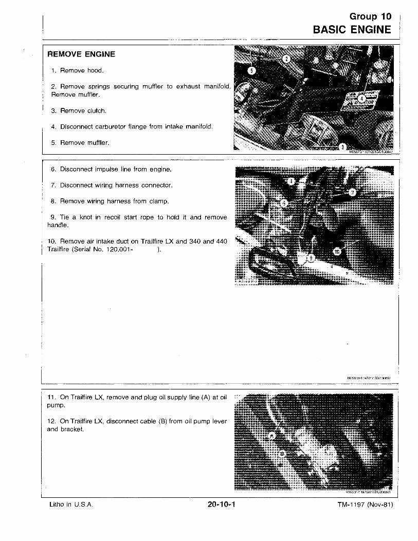
REMOVE ENGINE
1. Remove hood.
2. Remove springs securing muffler to exhaust manifold.Remove muffler.
3. Remove clutch.
4. Disconnect carburetor flange from intake manifold.
5. Remove muffler.
6. Disconnect impulse line from engine.
7. Disconnect wiring harness connector.
8. Remove wiring harness from clamp.
9. Tie a knot in recoil start rope to hold it and removehandle.
10. Remove air intake duct on Trailfire LX and 340 and 440Trailfire (Serial No. 120,001- ).
11. On Trailfire LX, remove and plug oil supply line (A) at oilpump.
12. On Trailfire LX, disconnect cable (8) from oil pump leverand bracket.
Group 10
BASIC ENGINE
M25680/1197/201 08/1 00681
.-:.;:;:\tti?M29231/1197/201081/200881
Litho in U.S.A. 20-10-1 TM-1197 (Nov-81)
Basic Engine
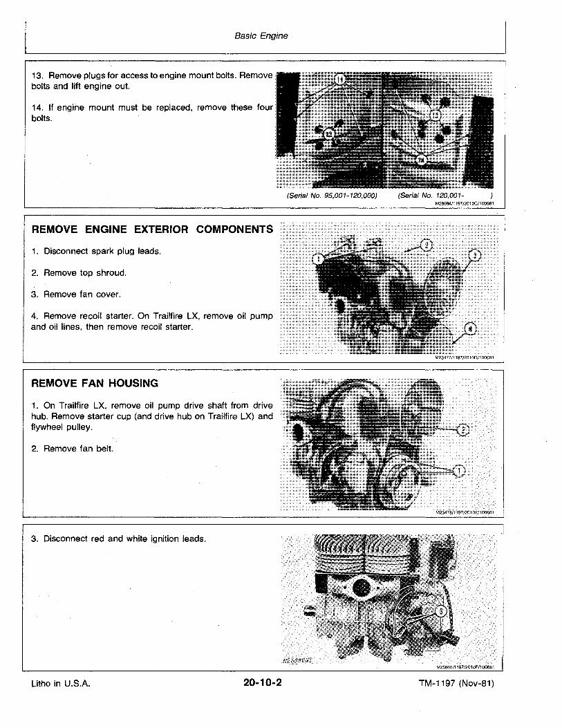
13. Remove plugs for access to engine mount bolts. Removebolts and lift engine out.
14. If engine' mount must be replaced, remove these fourbolts.
(Serial No. 95,001-120,000) (Serial No. 120,001M28694/1197/201OC/100681
REMOVE ENGINE EXTERIOR COMPONENTS
1. Disconnect spark plug leads.
2. Remove top shroud.
3. Remove fan cover.
4. Remove recoil starter; On Trailfire LX, remove oil pumpand oil lines, then remove recoil starter.
REMOVE FAN HOUSING
1. On Trailfire LX, remove oil pump drive shaft from drivehub. Remove starter cup (and drive hub on Trailfire LX) andflywheel pulley.
2.' Remove fan belt.
3. Disconnect red and white ignition leads.
Litho in U.S.A. 20-10-2 TM-1197 (Nov-81)
Basic Engine
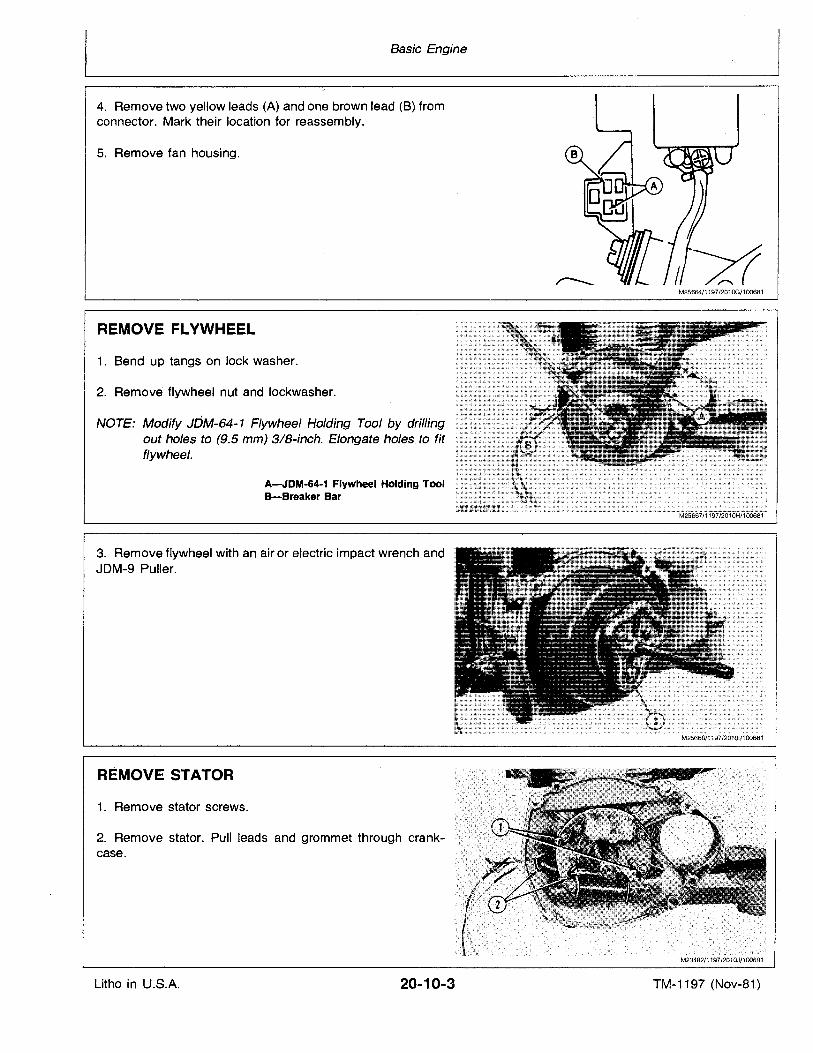
4. Remove two yellow leads (A) and one brown lead (B) fromconnector. Mark their location for reassembly.
5. Remove fan housing.
M25664/1197/201OG/100681
REMOVE FLVWHEEL
1. Bend up tangs on lock washer.
2. Remove flywheel nut and lockwasher.
NOTE: Modify JDM-64-1 Flywheel Holding Tool by drillingout holes to (9.5 mm) 3IB-inch. Elongate holes.to fitflywheel.
A-JDM·64-1 Flywheel Holding ToolB-Breaker Bar
3. Remove flywheel with an air or electric impact wrench andJDM-9 Puller.
REMOVE STATOR
1. Remove stator screws.
2. Remove stator. Pull leads and grommet through crankcase.
M23482/1197/201OJ/100681
Litho in U.S.A. 20-10-3 TM-1197 (Nov-at)
Basic Engine
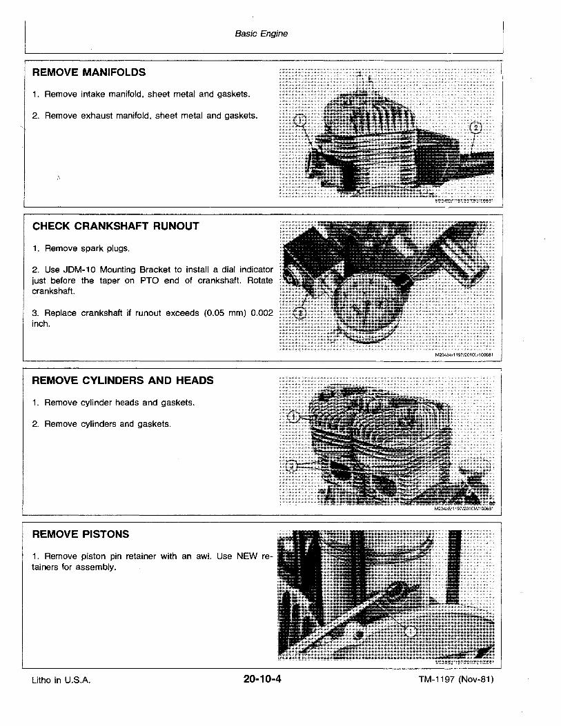
REMOVE MANIFOLDS
1. Remove intake manifold, sheet metal and gaskets.
2. Remove exhaust manifold, sheet metal and gaskets.
CHECK CRANKSHAFT RUNOUT
1. Remove spark plugs.
2. Use JDM-10 Mounting Bracket to install a dial indicatorjust before the taper on PTO end of crankshaft. Rotatecrankshaft.
3. Replace crankshaft if runout exceeds (0.05 mm) 0.002inch.
REMOVE CYLINDERS AND HEADS
1. Remove cylinder heads and gaskets.
2. Remove cylinders and gaskets.
REMOVE PISTONS
1. Remove piston pin retainer with an awl. Use NEW retainers for assembly.
M23484/1197/2010L/100681
Litho in U.S.A. 20-10-4 TM-1197 (Nov-81)
Basic Engine
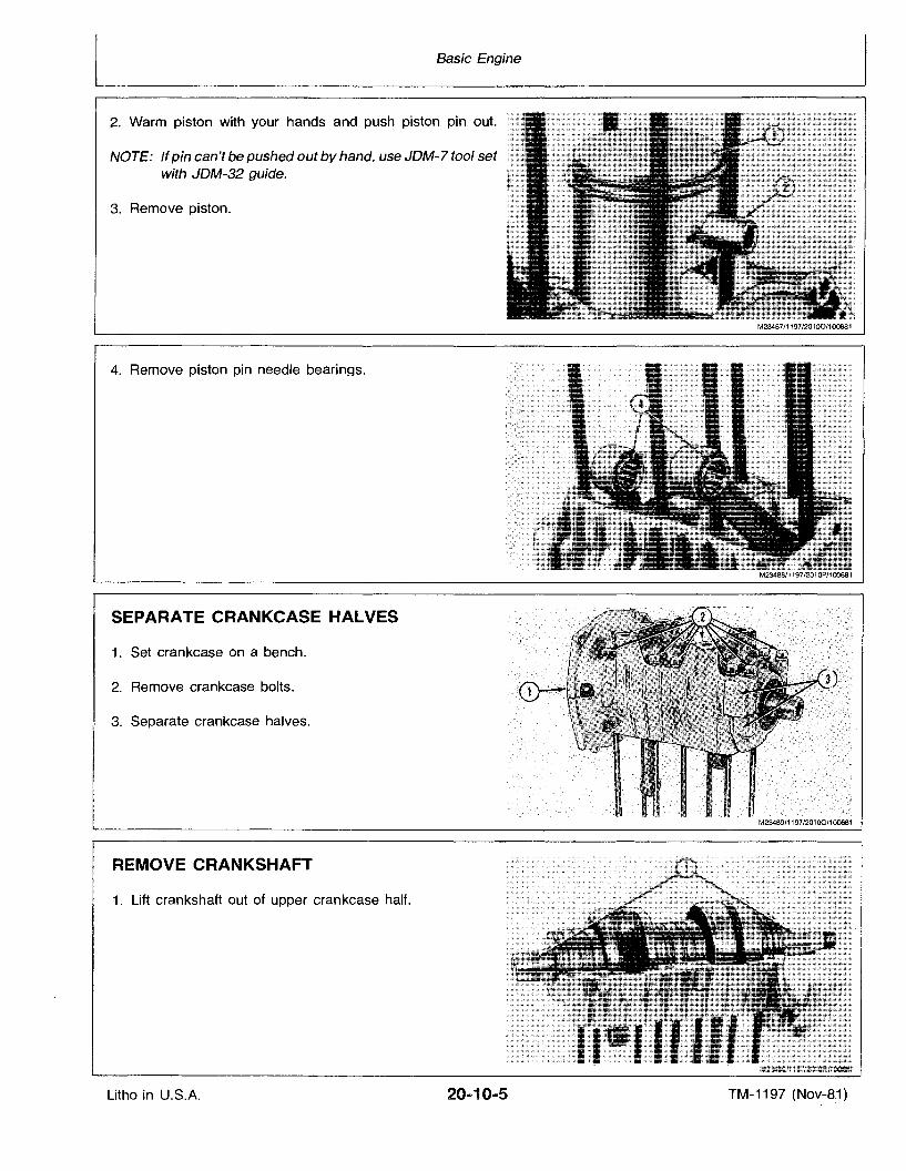
2. Warm piston with your hands and push piston pin out.
NOTE: If pin can't be pushed out by hand, use JDM-7 tool setwith JDM-32 guide.
3. Remove piston.
4. Remove piston pin needle bearings.
SEPARATE CRANKCASE HALVES
1. Set crankcase on a bench.
2. Remove crankcase bolts.
3. Separate crankcase halves.
M23489/1197/201 00/1 o06s1
REMOVE CRANKSHAFT
1. Lift crankshaft out of upper crankcase half.
Litho in U.S.A. 20 ...10-5 TM-1197 (Nov~8:1)
Basic Engine
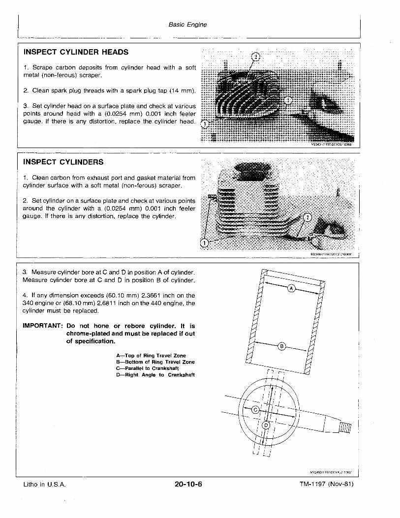
INSPECT CYLINDER HEADS
1. Scrape carbon deposits from cylinder head with a softmetal (non-ferous) scraper.
2. Clean spark plug threads with a spark plug tap (14 mm).
3. Set cylinder head on a surface plate and check at variouspoints around head with a (0.0254 mm) 0.001 inch feelergauge. If there is any distortion, replace the cylinder head.
M23491/1197/2010S/100681
INSPECT CYLINDERS
1. Clean carbon from exhaust port and gasket material fromcylinder surface with a soft metal (non-ferous) scraper.
2. Set cylinder on a surface plate and check at various pointsaround the cylinder with a (0.0254 mm) 0.001 inch feelergauge. If there is any distortion, replace the cylinder.
3. Measure cylinder bore at C and 0 in position A of cylinder.Measure cylinder bore at C and D in position B of cylinder.
4. If any dimension exceeds (60.10 mm) 2.3661 inch on the340 engine or (68.10 mm) 2.6811 inch on the 440 engine, thecylinder must be replaced.
IMPORTANT: Do not hone or rebore cylinder. It ischrome-plated and must be replaced if outof specification.
A-Top of Ring Travel Zonea-Bottom of Ring Travel ZoneC-Parallel to CrankshaftD-Right Angle to Crankshaft
M23492/1197J2010T/100681
M23493/1197/201OU/110681
Litho in U.S.A. 20-10-6 TM-1197 (Nov-81)
Basic Engine
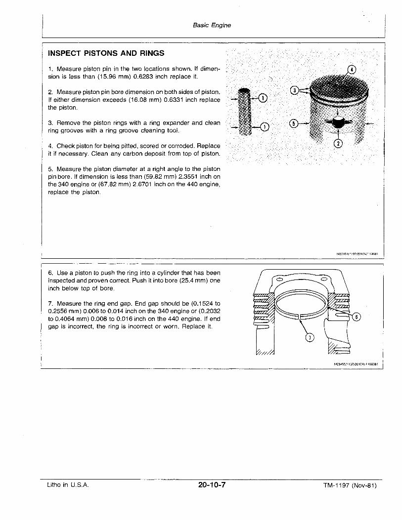
INSPECT PISTONS AND RINGS
1. Measure piston pin in the two locations shown. If dimension is less than (15.96 mm) 0.6283 inch replace it.
2. Measure piston pin bore dimension on both sides of piston.If either dimension exceeds (16.08 mm) 0.6331 inch replacethe piston.
3. Remove the piston rings with a ring expander and cleanring grooves with a ring groove cleaning tool.
4. Check piston for being pitted, scored or corroded. Replaceit if necessary. Clean any carbon deposit from top of piston.
5. Measure the piston diameter at a right angle to the pistonpin bore. If dimension is less than (59.82 mm) 2.3551 inch onthe 340 engine or (67.82 mm) 2.6701 inch on the 440 engine,replace the piston.
6. Use a piston to push the ring into a cylinder that has beeninspected and proven correct. Push it into bore (25.4 mm) oneinch below top of bore.
7. Measure the ring end gap. End gap should be (0.1524 to0.2556 mm) 0.006 to 0.014 inch on the 340 engine or (0.2032to 0.4064 mm) 0.008 to 0.016 inch on the 440 engine. If endgap is incorrect, the ring is incorrect or worn. Replace it.
M23494/1197/2010V/110681
M2349S/1197/2010W/1106081
Litho in U.S.A. TM-1197 (Nov-81)
Basic Engine
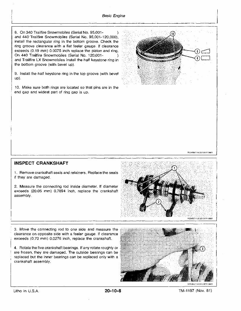
8. On 340 Trailfire Snowmobiles (Serial No. 95,001- )and 440:-Trailfire Snowmobiles (Serial No. 95,001-i20,000),installthe rectangular ring in the bottom groove. Check thering groove clearance with a flat feeler gauge. If clearanceexceeds (0.19 mm) 0.0075 inch replace the piston and ring.On 440 Trailfire Snowmobiles (Serial No. 120,001- )and Trailfire LX Snowmobiles install the half keystone ring inthe bottom groove (with bevel up).
9. Install the half keystone ring in the top groove (with bevelup).
10. Make sure both rings are located so that pins are in theend gap and widest part of ring gap is up.
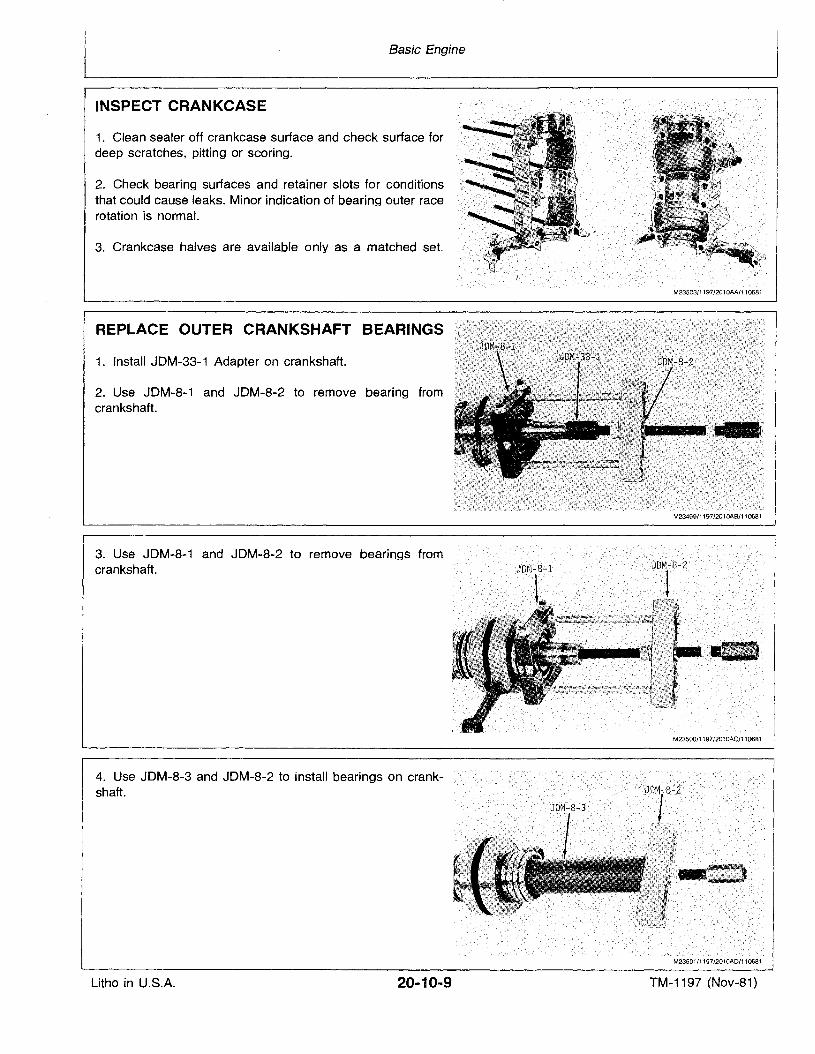
INSPECT CRANKSHAFT
1. Remove crankshaft seals and retainers. Replace the sealsif they are damaged.
2. Measure the connecting rod inside diameter. If diameterexceeds (20.05 mm) 0.7894 inch, replace the crankshaftassembly.
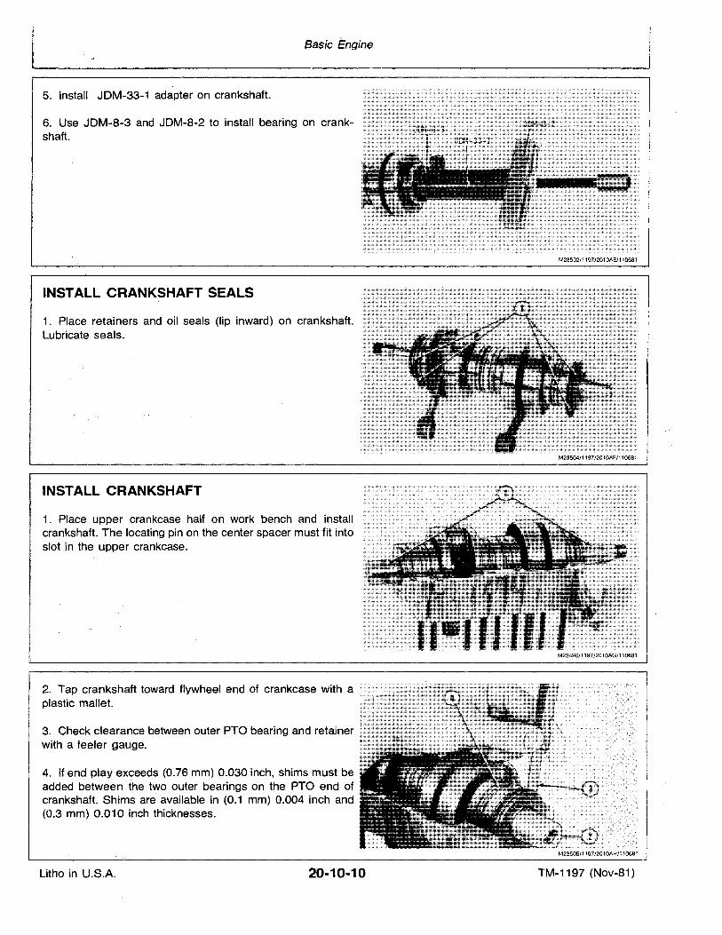
3. Move the connecting rod to one side and measure theclearance on opposite side with a feeler gauge. If clearanceexceeds (0.70 mm) 0.0276 inch, replace the crankshaft.
4. Rotate the five crankshaft bearings. If any rotate roughly orare frozen, they are damaged. The outside bearings can bereplaced but the inner bearings can be replaced only with acrankshaft assembly.
M23496/1197/2010X/110681
M23497/1197/2010Y/110681
M25398/1197/2010Z/110681
Litho in U.S.A. 20-10-8 TM-1197 (Nov. 81)
Basic Engine
INSPECT CRANKCASE
1. Clean sealer off crankcase surface and check surface fordeep scratches, pitting or scoring.
2. Check bearing surfaces and retainer slots for conditionsthat could cause leaks. Minor indication of bearing outer racerotation is normal.
3. Crankcase halves are available only as a matched set.
REPLACE OUTER CRANKSHAFT BEARINGS
1. Install JDM-33-1 Adapter on crankshaft.
2. Use JDM-8-1 and JDM-8-2 to remove bearing fromcrankshaft.
3. Use JDM-8-1 and JDM-8-2 to remove bearings fromcrankshaft.
4. Use JDM-8-3 and JDM-8-2 to install bearings on crankshaft.
M23503/1197/2010AA/110681
M23499/1197/2010AB/110681
M23500/1197/201 OAC/110681
'''." " ".M23501/1197/201QAD/110681
Litho in U.S.A. 20-10-9 TM-1197 (Nov-81)
Basic Engine
5. Install JDM-33-1 adapter on crankshaft.
6. Use JDM-8-3 and JDM-8-2 to install bearing on crankshaft.
INSTALL CRANKSHAFT SEALS
1. Place retainers and oil seats (lip inward) on crankshaft.Lubricate seals.
INSTALL CRANKSHAFT
1. Place upper crankcase half on work bench and installcrankshaft. The locating pin on the center spacer must fit intoslot in the upper crankcase.
2. Tap crankshaft toward flywheel end of crankcase with aplastic mallet.
3. Check clearance between outer PTO bearing and retainerwith a feeler gauge.
4. If end play exceeds (0.76 mm) 0.030 inch, shims must beadded between the two outer bearings on the PTO end ofcrankshaft. Shims are available in (0.1 mm) 0.004 inch and(0.3 mm) 0.010 inch thicknesses.
M23502/1197/2010AE/110681
M23490/1197/2010AG/110681
M23505/1197/2010AH/110681
Litho in U.S.A. 20-10-10 TM-1197 (Nov-81)
Basic Engine
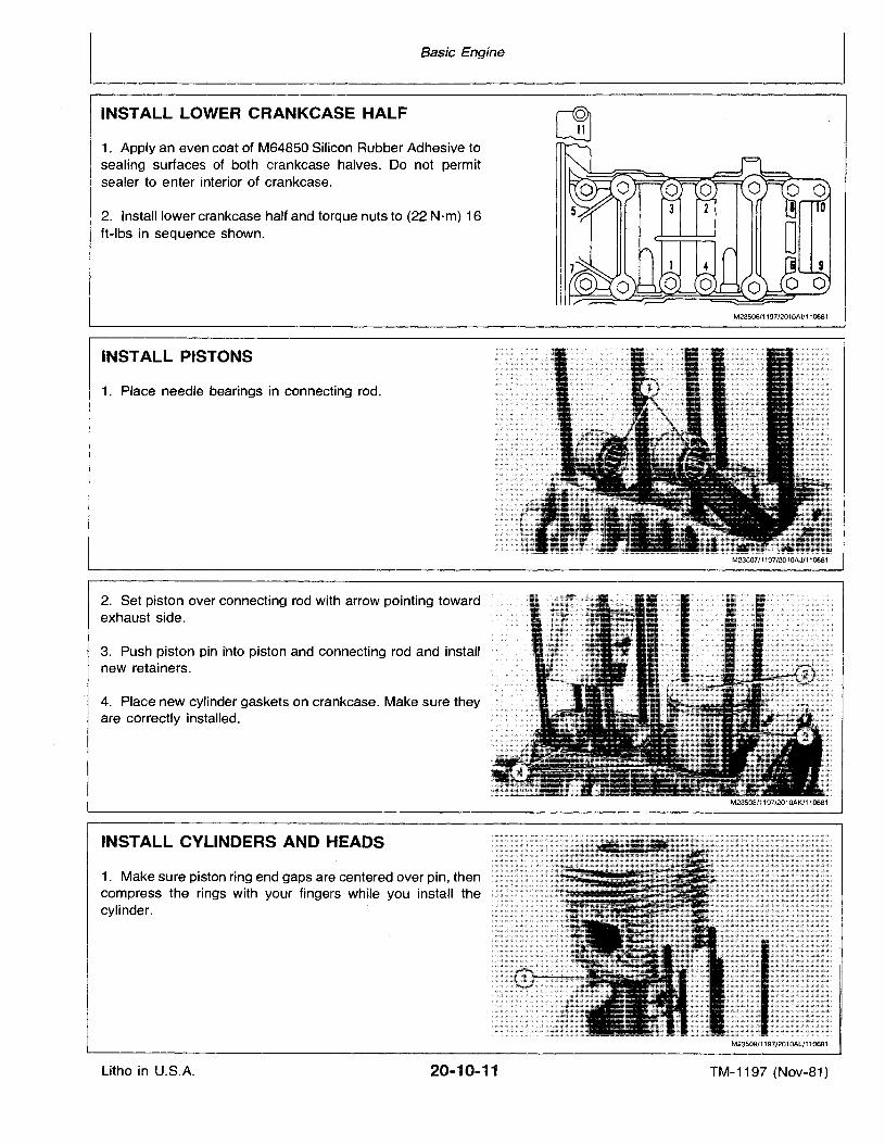
INSTALL LOWER CRANKCASE HALF
1. Apply an even coat of M64850 Silicon Rubber Adhesive tosealing surfaces of both crankcase halves. Do not permitsealer to enter interior of crankcase.
2. Install lower crankcase half and torque nuts to (22 N·m) 16ft-Ibs in sequence shown.
M23506/1197/2010AI/110681
INSTALL PISTONS
1. Place needle bearings in connecting rod.
2. Set piston over connecting rod with arrow pointing towardexhaust side.
3. Push piston pin into piston and connecting rod and installnew retainers.
4. Place new cylinder gaskets on crankcase. Make sure theyare correctly installed.
INSTALL CYLINDERS AND HEADS
1. Make sure piston ring end gaps are centered over pin, thencompress the rings with your fingers while you install thecylinder.
M23507/1197/2010AJ/110681
M23509/1197/2010Al/110681
Litho in U.S.A. 20-10-11 TM-1197 (Nov-81)
Basic Engine
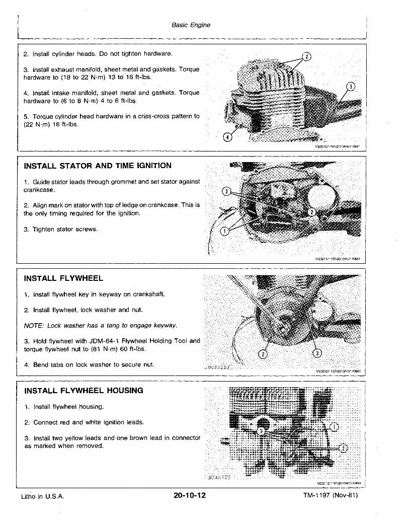
2. Install cylinder heads. Do not tighten hardware.
3. Install exhaust manifold, sheet metal and gaskets. Torquehardware to (18 to 22 N'm) 13 to 16 ft-Ibs.
4. Install intake manifold, sheet metal and gaskets. Torquehardware to (6 to 8 N·m) 4 to 6 ft-Ibs.
5. Torque cylinder head hardware in a criss-cross pattern to(22 N·m) 16 ft-Ibs.
INSTALL STATOR AND TIME IGNITION
1. Guide stator leads through grommet and set stator againstcrankcase.
2. Align mark on stator with top of ledge on crankcase. This isthe only timing required for the ignition.
3. Tighten stator screws.
INSTALL FLYWHEEL
1. Install flywheel key in keyway on crankshaft.
2. Install flywheel, lock washer and nut.
NOTE: Lock washer has a tang to engage keyway.
torque flywheel nut to (81 N·m) 60 ft-Ibs.
4. Bend tabs on lock washer to secure nut.
INSTALL FLYWHEEL HOUSING
1. Install flywheel housing.
2. Connect red and white ignition leads.
3. Install two yellow leads and one brown lead in connectoras marked when removed.
M23510/1197J2010AM/110681
M23513/1197/2010AP/110681
Litho in U.S.A. 20-10-12 TM-1197 (Nov-81)
Basic Engine
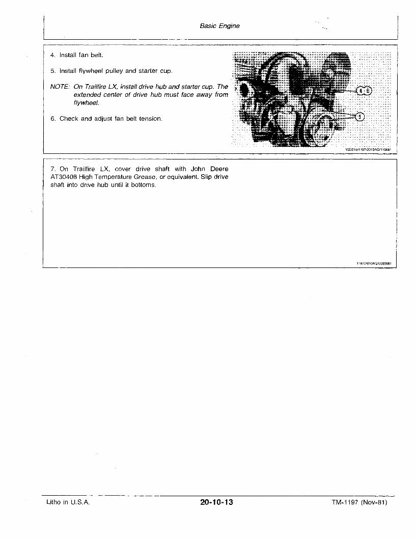
4. Install Ian belt.
5. Instafl flywheel pulley and starter cup.
NOTE: On Trailfire LX, install drive hub and starter cup. Theextended center of drive hub must face away fromflywheel.
6. Check and adjust fan belt tension.
7. On Trailfire LX, cover drive shaft with John DeereAT3040B High Temperature Grease, or equivalent. Slip driveshaft into drive hub until it bottoms.
M23514/1197/2010AQ/110681
1197/2010AQ1/200881
Litho in U.S.A. 20-10-13 TM-1197 (Nov-81)
Basic Engine
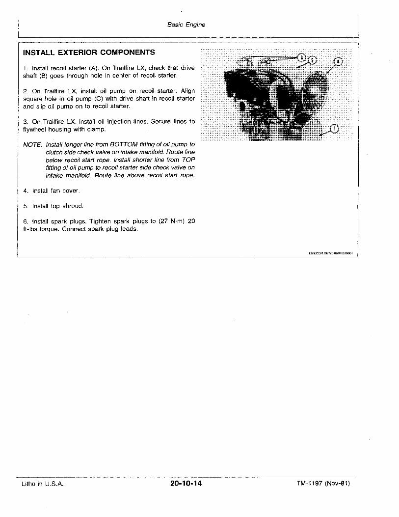
INSTALL EXTERIOR COMPONENTS
1. Install recoil starter (A). On Trailfire LX, check that driveshaft (8) goes through hole in center of recoil starter.
2. On Trailtire LX, install oil pump on recoil starter. Alignsquare hole in oil pump (C) with drive shaft in recoil starterand slip oil pump on to recoil starter.
3. On Trailfire LX, install oil injection lines. Secure lines toflywheel housing with clamp.
NOTE: Install longer line from BOTTOM fitting of oil pump toclutch side check valve on intake manifold. Route linebelow recoil start rope. Install shorter line from TOPfitting of oil pump to recoil starter side check valve onintake manifold. Route line above recoil start rope.
4. Install fan cover.
5. Install top shroud,
6. Install spark plugs. Tighten spark plugs to (27 N·m) 20ft-Ibs torque. Connect spark plug leads.
M29233/1197/2010AR/200881
Litho in U.S.A. 20-10-14 TM-1197 (Nov-81)
·Basic Engine
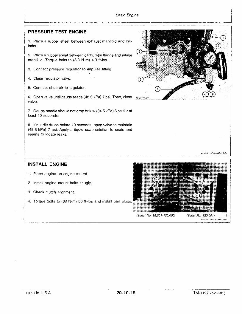
PRESSURE TEST ENGINE
1. Place a rubber sheet between exhaust manifold and cylinder.
2. Place a rubber sheet between carburetor flange and intakemanifold. Torque bolts to (5.8 N·m) '4.3 ft-Ibs.
3. Connect pressure regulator to impulse fitting.
4. Close regulator valve.
5. Connect shop air to regulator.
6. Open valve until gauge reads (48.3 kPa) 7 psi. Then, closevalve.
7. Gauge needle should not drop below (34.5 kPa) 5 psi for atleast 10 seconds.
8. If needle drops before 10 seconds, open valve to maintain(48.3 kPa) 7 psi. Apply a liquid soap solution to seals andseams to locate leaks.
INSTALL ENGINE
1. Place engine on engine, mount.
2. Install engine mount bolts snugly.
3. Check clutch alignment.
4. Torque bolts to (68 N·m) 50 ft-Ibs and install pan plugs.
M23516/1197/2010AS/11Q681
Litho in U.S.A. 20-10..15
(Serial No. 95,001-120,000) (Serial No. 120,001-M30171/1197/2010AT/11Q681
TM-1197 (Nov-81)
Basic Engine
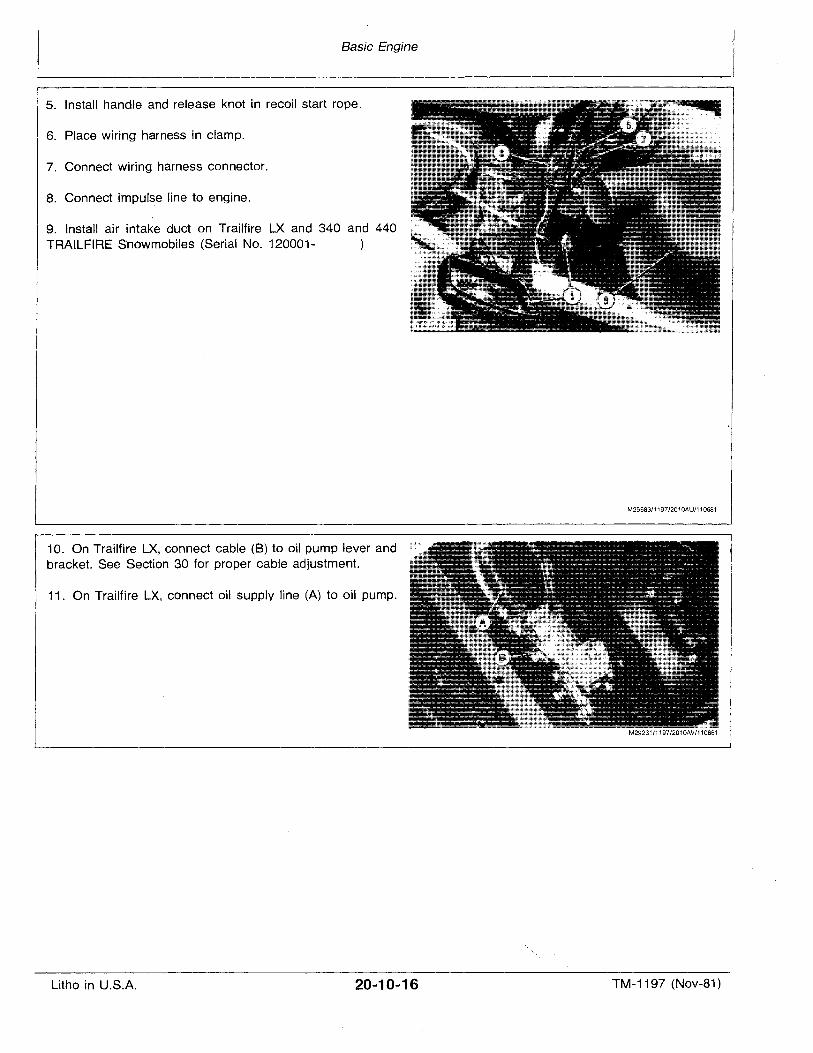
5. Install handle and release knot in recoil start rope.
6. Place wiring harness in clamp.
7. Connect wiring harness connector.
8. Connect impulse line to engine.
9. Install air intake duct on Trailfire LX and 340 and 440TRAILFIRE Snowmobiles (Serial No. 120001-
10. On Trailfire LX, connect cable (B) to oil pump lever andbracket. See Section 30 for proper cable adjustment.
11. On Trailfire LX, connect oil supply line (A) to oil pump.
M25683/1197/2010AU/110681
M29231/1197/2010AV/110881
Litho in U.S.A. 20-10-16 TM-1197 (Nov-81)
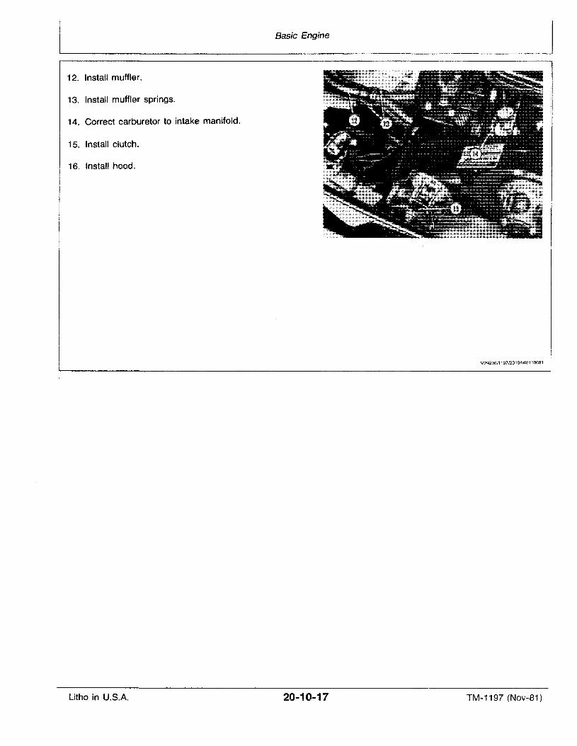
12. Install muffler.
13. Install muffler springs.
14. Correct carburetor to intake manifold.
15. Install clutch.
16. Install hood.
Basic Engine
M29236/1197/2010AW/110681
Litho in U.S.A. 20-10-17 TM-1197 (Nov-81)

Litho in U.S.A.
Basic Engine
20-10-18 TM-1197 (Nov-81)
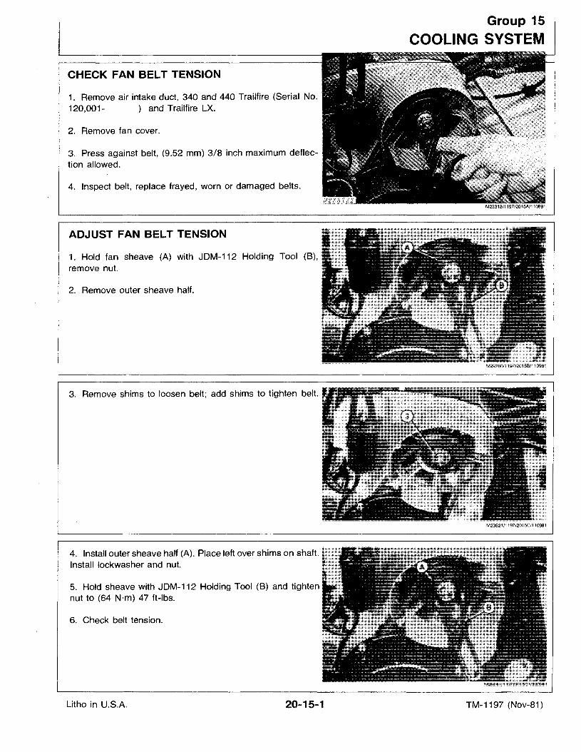
CHECK FAN BELT TENSION
1. Remove air intake duct, 340 and 440 Trailfire (Serial No.120,001- ) and Trailfire LX.
2. Remove fan cover.
3. Press against belt, (9.52 mm) 3/8 inch maximum deflection allowed.
4. Inspect belt, replace frayed, worn or damaged belts.
ADJUST FAN BELT TENSION
1. Hold fan sheave (A) with JDM-112 Holding Tool (B),.remove nut.
2. Remove outer sheave half.
3. Remove shims to loosen belt; add shims to tighten belt.:'
4. Install outer sheave half (A). Place left over shims on shaft.Install lockwasher and nut.
5. Hold sheave with JDM-112 Holding Tool (8) and tighten i
nut to (64 N·m) 47 ft-Ibs.
6. Check belt tension.
Group 15
COOLING SYSTEM
Litho in U.S.A. 20-15-1 TM-1197 (Nov-81)
Cooling System
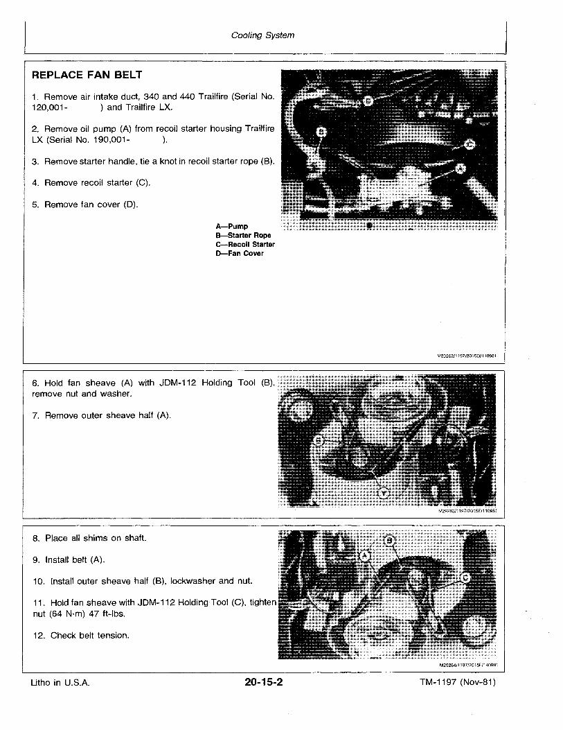
REPLACE FAN BELT
1. Remove air intake duct, 340 and 440 Trailfire (Serial No.120,001- ) and Trailfire LX.
2. Remove oil pump (A) from recoil starter housing TrailfireLX (Serial No. 190,001- ).
3. Remove starter handle, tie a knot in recoil starter rope (B).
4. Remove recoil starter (C).
5. Remove fan cover (D).
A-PumpB-Starter Ropee-Recoil StarterD-Fan Cover
6. Hold fan sheave (A) with JDM-112 Holding Tool (B),remove nut and washer.
7. Remove outer sheave half (A).
8. Place all shims on shaft.
9. Install belt (A).
10. Install outer sheave half (B), lockwasher and nut.
11. Hold fan sheave with JDM-112 Holding-Tool (C), tightennut (64 N·m) 47 ft-Ibs.
12. Check belt tension.
M29262/1197/2015D/110981
M29264/1197/2015F/140981
Litho in U.S.A. 20-15-2 TM-1197 (Nov-81)
Cooling System
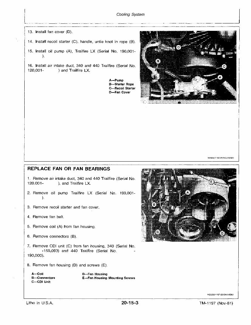
13. Install fan cover (0).
14. Install recoil starter (C), handle, untie knot in rope (8).
15. Install oil pump (A), Trailfire LX (Serial No. 190,001).
16. Install air intake duct, 340 and 440 Trailfire (Serial No.120,001- ) and Trailfire LX.
A-PumpB-Starter RopeC-Recoil StarterD-Fan Cover
REPLACE FAN OR FAN BEARINGS
1. Remove air intake duct, 340 and 440 Trailfire (Serial No.120,001- ), and Trailfire LX.
2. Remove oil pump Trailfire LX (Serial No. 190,001).
3. Remove recoil starter and fan cover.
4. Remove fan belt.
5. Remove coil (A) from fan housing.
6. Remove connectors (8).
7. Remove COl unit (C) from fan housing, 340 (Serial No.-155,093) and 440 Trailfire (Serial No.
190,000).
8. Remove fan housing (0) and screws (E).
M29262/1197/2015G/220981
A-CoilB-ConnectorsC-CDI Unit
Litho in U.S.A.
D-Fan HousingE-Fan Housing Mounting Screws
20-15-3
M29266/1197/2015H/140981
TM-1197 (Nov-81)
Cooling System
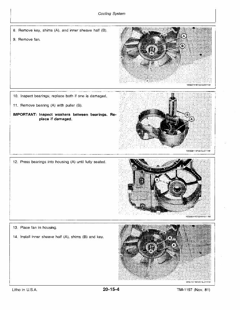
8. Remove key, shims (A), and inner sheave half (B).
9. Remove fan.
10. Inspect bearings; replace both if one is damaged.
11. Remove bearing (A) with puller (B).
IMPORTANT: Inspect washers between bearings. Replace if damaged.
12. Press bearings into housing (A) until fully seated.
13. Place fan in housing.
14. Install inner sheave half (A), shims (B) and key.
M29267/1197/20151/211181
M29268/1197/2015J/211181
M29269/1197/2015K/211181
M29270/1197/2015L/211181
Litho in U.S.A. 20-15-4 TM-1197 (Nov. 81)
Cooling System
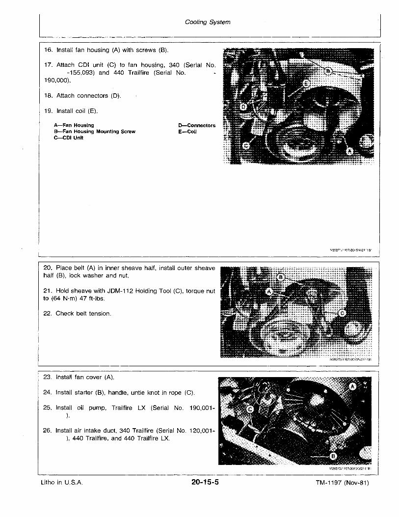
16. Install fan housing (A) with screws (B).
18. Attach connectors (0).
17. Attach COl unit (C) to fan housing, 340 (Serial No.-155,093) and 440 Trailfire (Serial No.
190,000).
D-ConnectorsE-Coil
A-Fan HousingB-Fan Housing Mounting ScrewC-CDI Unit
19. Install coil (E).
M29271/1197/2015M/211181
20. Place belt (A) in inner sheave half, install outer sheavehalf (B), lock washer and nut.
21. Hold sheave with JOM-112 Holding Tool (C), torque nutto (64 N'm) 47 ft-Ibs.
22. Check belt tension.
23. Install fan cover (A).
24. Install starter (8), handle, untie knot in rope (C).
25. Install oil pump, Trailfire LX (Serial No. 190,001).
26. Install air intake duct, 340 Trailfire (Serial No. 120,001), 440 Trailfire, and 440 Trailfire LX.
M29273/1197/20150/211181
Litho in U.S.A. 20-15-5 TM-1197 (Nov-81)

Litho in U.S.A.
Cooling System
20-15-6 TM-1197 (Nov-81)
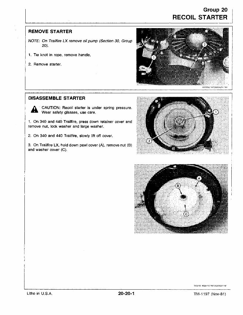
REMOVE STARTER
NOTE: On Trai/fire LX remove oil pump (Section 30, Group20).
1. Tie knot in rope, remove handle,
2. Remove starter.
DISASSEMBLE STARTER
A CAUTION: Recoil starter is under spring pressure.- Wear safety glasses, use care.
1. On 340 and 440. Trailfire, press down retainer cover andremove nut, lock washer and large washer.
2. On 340 and 440 Trailfire, slowly lift off cover.
3. On Trailfire LX, hold down pawl cover (A), remove nut (B)and washer cover (e).
Group 20
RECOIL STARTER
M23533 M29274/1197/2020B/211181
Litho in U.S.A. 20-20-1 TM-1197 (Nov-81)
Recoil Starter
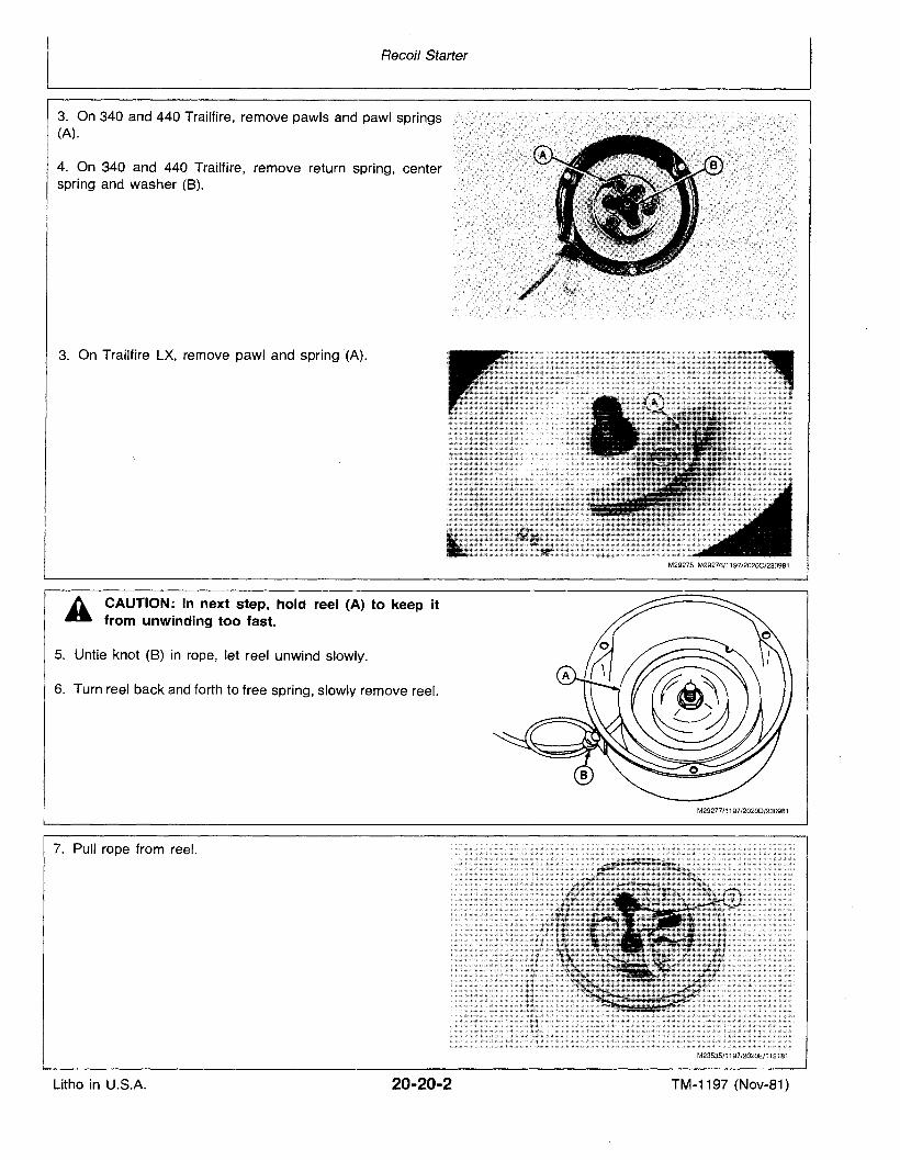
3. On 340 and 440 Trailfire, remove pawls and pawl springs(A).
4. On 340 and 440 Trailfire, remove return spring, centerspring and washer (B).
3. On Trailfire LX, remove pawl and spring "(A).
A CAUTION: In next step, hold reel (A) to keep it~ from unwinding too fast.
5. Untie knot (8) in rope, let reel unwind slowly.
6. Turn reel back and forth to free spring, slowly remove reel.
7. Pull rope from reel.
M29275 M29276/1197/202OC/230981
M29277/1197 /2020D/230981
M23535/1197/2020E/112181
Litho in U.S.A. 20-20-2 TM-1197 (Nov-81)
Recoil Starter
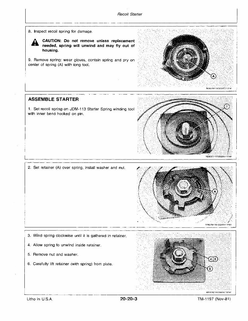
8. Inspect recoil spring for damage.
9. Remove spring: wear gloves, contain spring and pry oncenter of spring (A) with long tool.
A CAUTION: Do not remove unless replacementneeded, spring will unwind and may fly out ofhousing.
M29278/1197/2020F/112181
ASSEMBLE STARTER
1. Set recoil spring on JDM-113 Starter Spring winding toolwith inner bend hooked on pin.
2. Set retainer (A) over spring, install washer and nut.
3. Wind spring clockwise until it is gathered in retainer.
4. Allow spring to unwind inside retainer.
5. Remove nut and washer.
6. Carefully lift retainer (with spring) from plate.
./,f
M23537/1197/2020G/112181
M29279/1197/2020H/112181
M23539/1197/20201/112181
Litho in U.S.A. TM-1197 (Nov-81)
Recoil Starter
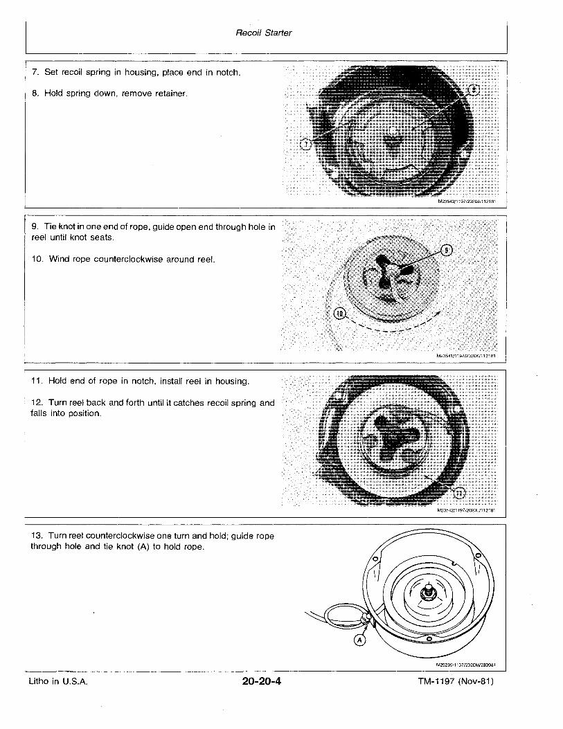
7. Set recoil spring in housing, place end in notch.
8. Hold spring down, remove retainer.
9. Tie knot in one end of rope, guide open end through hole inreel until knot seats.
10. Wind rope counterclockwise around reel.
11. Hold end of rope in notch, install reel in housing.
12. Turn reel back and forth until it catches recoil spring andfalls into position.
13. Turn reel counterclockwise one turn and hold; guide ropethrough hole and tie knot (A) to hold rope.
M23540/1197/202OJ/112181
M23541/1197/2020K/112181
M23542/1197J2020l/112181
M29295/1197/2020MJ230981
Litho in U.S.A. 20-20-4 TM-1197 (Nov-81)
Recoil Starter
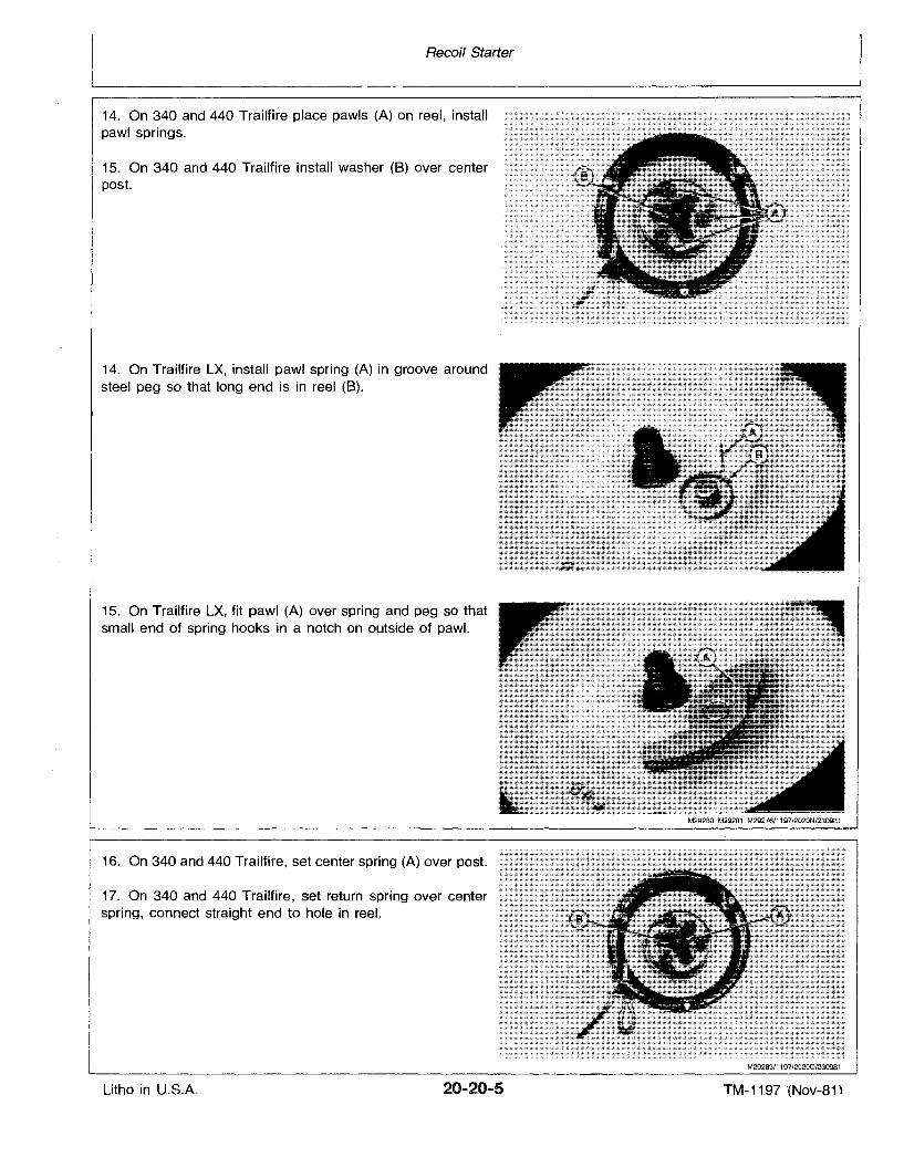
14. On 340 and 440 Trailfire place pawls (A) on reel, installpawl springs.
15. On 340 and 440 Trailfire install washer (B) over centerpost.
14. On Trailfire LX, install pawl spring (A) in groove aroundsteel peg so that long end is in reel (B).
15. On Trailfire LX, fit pawl (A) over spring and peg so thatsmall end of spring hooks in a notch on outside of pawl.
16. On 340 and 440 Trailfire, set center spring (A) over post.
17. On 340 and 440 Trailfire, set return spring over centerspring, connect straight end to hole in reel.
M29283/1197/20200/230981
Litho in U.S.A. 20-20-5 TM-1197 "(Nov-81 \
Recoil Starter
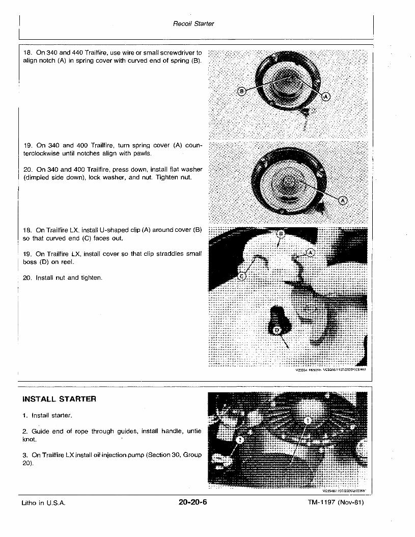
18. On 340 and 440 Trailfire, use wire or small screwdriver toalign notch (A) in spring cover with curved end of spring (B).
19. On 340 and 400 Trailfire, turn spring cover (A) counterclockwise until notches align with pawls.
20. On 340 and 400 Trailfire, press down, install flat washer(dimpled side down), lock washer, and nut. Tighten nut.
18. On Trailfire LX, install U-shaped clip (A) around cover (8)so that curved end (C) faces out.
19. On Trailfire LX, install cover so that clip straddles smallboss (D) on reel.
20. Install nut and tighten.
INSTALL STARTER
1. Install starter.
2. Guide end of rope through guides, install handle, untieknot.
3. On Trailfire LX install oil injection pump (Section 30, Group20).
M23548/1197/20200/230981
Litho in U.S.A. 20-20-6 TM-1197 (Nov-81)
Group 25
SPECIFICATIONS
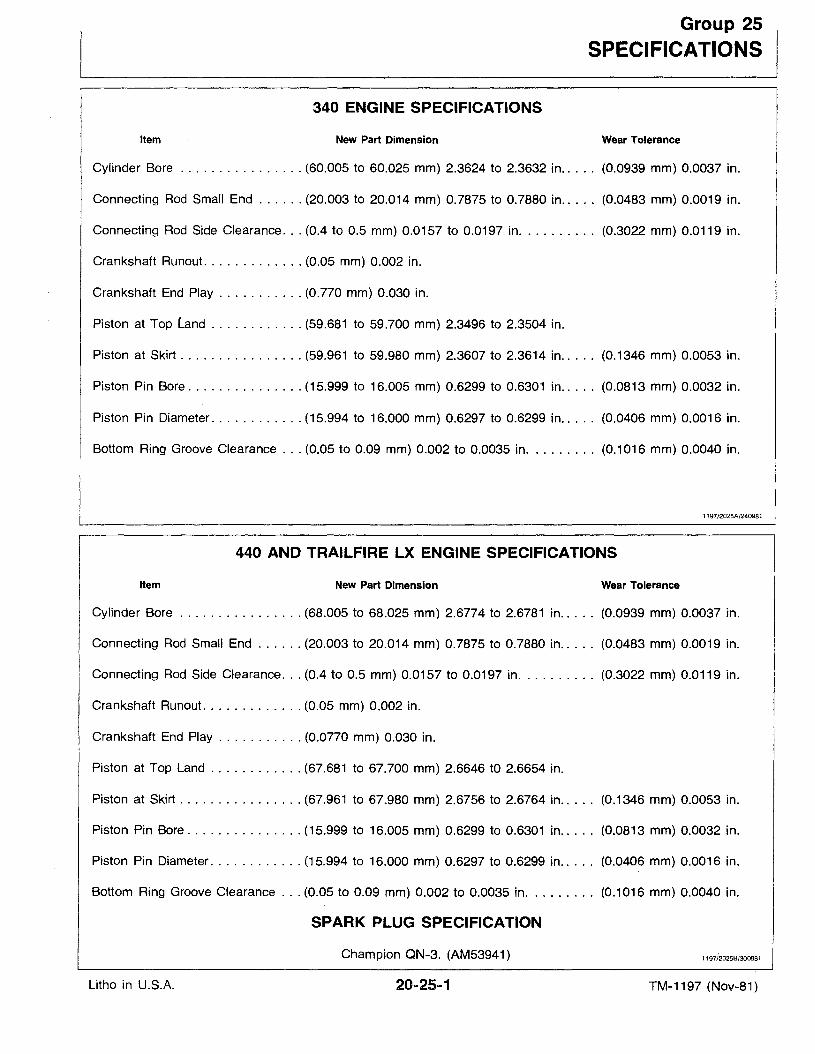
340 ENGINE SPECIFICATIONS
Item New Part Dimension Wear Tolerance
Cylinder Bore (60.005 to 60.025 mm) 2.3624 to 2.3632 in.. . .. (0.0939 mm) 0.0037 in.
Connecting Rod Small End (20.003 to 20.014 mm) 0.7875 to 0.7880 in (0.0483 mm) 0.0019 in.
Connecting Rod Side Clearance... (0.4 to 0.5 mm) 0.0157 to 0.0197 in. . . . . . . . . . (0.3022 mm) 0.0119 in.
Crankshaft Runout (0.05 mm) 0.002 in.
Crankshaft End Play (0.770 mm) 0.030 in.
Piston at Top land (59.681 to 59.700 mm) 2.3496 to 2.3504 in.
Piston at Skirt (59.961 to 59.980 mm) 2.3607 to 2.3614 in (0.1346 mm) 0.0053 in.
Piston Pin Bore (15.999 to 16.005 mm) 0.6299 to 0.6301 in.. . . . (0.0813 mm) 0.0032 in.
Piston Pin Diameter (15.994 to 16.000 mm) 0.6297 to 0.6299 in.. . . . (0.0406 mm) 0.0016 in.
Bottom Ring Groove Clearance (0.05 to 0.09 mm) 0.002 to 0.0035 in (0.1016 mm) 0.0040 in.
1197/2025A/240981
440 AND TRAILFIRE LX ENGINE SPECIFICATIONS
Item New Part Dimension Wear Tolerance
Cylinder Bore (68.005 to 68.025 mm) 2.6774 to 2.6781 in (0.0939 mm) 0.0037 in.
Connecting Rod Small End (20.003 to 20.014 mm) 0.7875 to 0.7880 in (0.0483 mm) 0.0019 in.
Connecting Rod Side Clearance (0.4 to 0.5 mm) 0.0157 to 0.0197 in (0.3022 mm) 0.0119 in.
Crankshaft Runout (0.05 mm) 0.002 in.
Crankshaft End Play (0.0770 mm) 0.030 in.
Piston at Top Land (67.681 to 67.700 mm) 2.6646 to 2.6654 in.
Piston at Skirt (67.961 to 67.980 mm) 2.6756 to 2.6764 in (0.1346 mm) 0.0053 in.
Piston Pin Bore (15.999 to 16.005 mm) 0.6299 to 0.6301 in (0.0813 mm) 0.0032 in.
Piston Pin Diameter (15.994 to 16.000 mm) 0.6297 to 0.6299 in.. . . . (0.0406 mm) 0.0016 in.
Bottom Ring Groove Clearance ... (0.05 to 0.09 mm) 0.002 to 0.0035 in. . . . . . . . . (0.1016 mm) 0.0040 in.
SPARK PLUG SPECIFICATION
Litho in U.S.A.
Champion ON-3. (AM53941) 1197/~025B/300981
TM-1197 (Nov-81)
Specifications
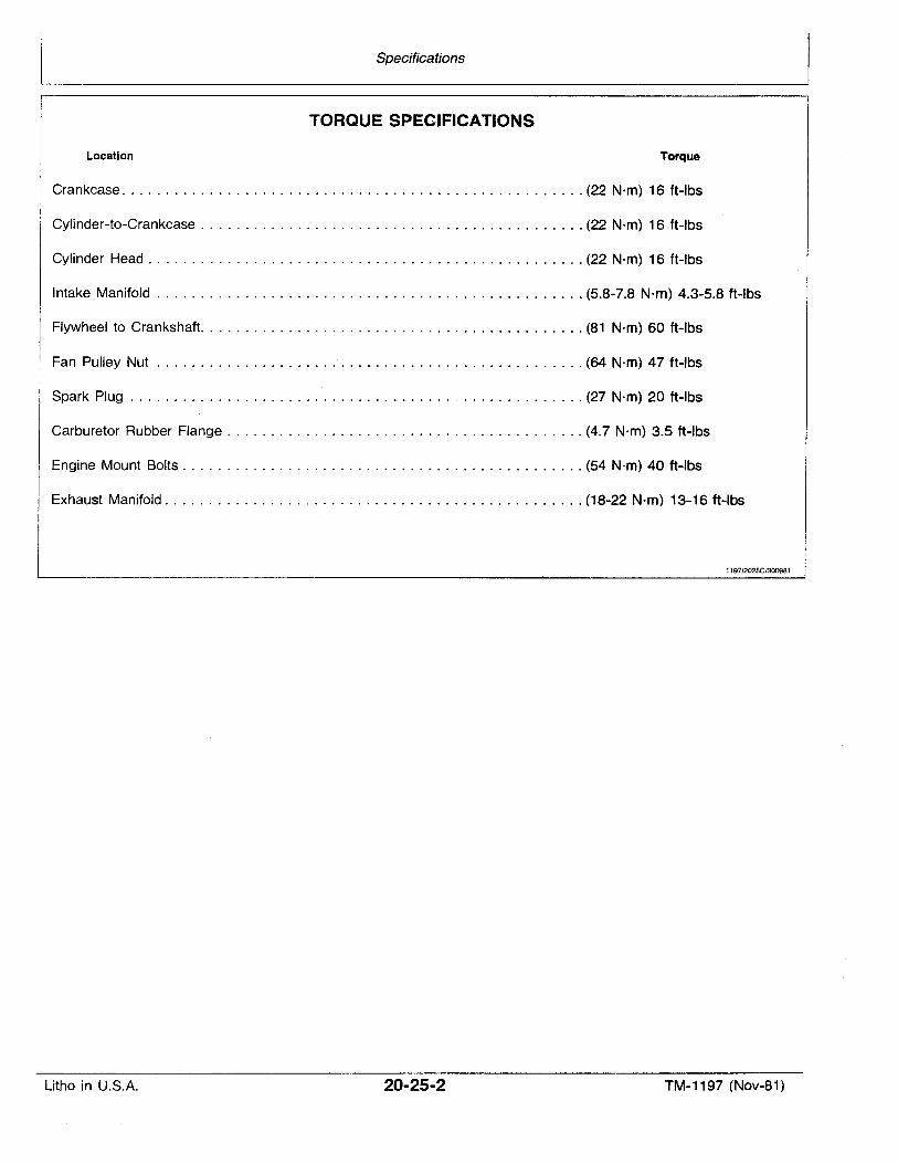
TORQUE SPECIFICATIONS
Location Torque
Crankcase (22 N'm) 16 ft-Ibs
Cylinder-to-Crankcase (22 Nrn) 16 ft-Ibs
Cylinder Head (22 Nrn) 16 ft-Ibs
Intake Manifold (5.8-7.8 N·m) 4.3-5.8 ft-Ibs
Flywheel to Crankshaft. (81 N·m) 60 ft-Ibs
Fan Pulley Nut (64 N·m) 47 ft-Ibs
Spark Plug ' (27 N·m) 20 ft-Ibs
Carburetor Rubber Flange (4.7 N'm) 3.5 ft-Ibs
Engine Mount Bolts (54 N·m) 40 ft-Ibs
Exhaust Manifold (18-22 N·m) 13-16 ft-Ibs
1197/2025C/300981
Litho in U.S.A. 20-25-2 TM-1197 (Nov-81)
Section 30FUEL SYSTEM
CONTENTS
PageGROUP 5 - GENERAL INFORMATIONPrinciple of Operation (340 and 440
Trailfire) . . . . . . . . . . . . . . . . . . . . . . . . .. 30-05-1Principle of Operation (Trailfire LX) 30-05-2Carburetor . . . . . . . . . . . . . . . . . . . . . . . .30-05-3Choke System . . . . . . . . . . . . . . . . . . . . .30-05-4Float System 30-05-4Pilot System (Idle and Slow Speed) 30-05-5Main System ....'. . . . . . . . . . . . . . . . . . . 30-05-5Diagnose Malfunctions. . . . . . . . . . . . . . . . 30-05-6
GROUP 10 - MIKUNI CARBURETORRemove Carburetor 30-10-1Disassemble Carburetor 30-10-1Inspect and Repair Carburetor 30-10-3Assemble Carburetor . . . . . . . . . . . . . . . .30-10-3Install Carburetor 30-10-5340 Trailfire Snowmobile
Altitude Chart 30-10-8440 Trailfire and Trailfire LX
Altitude Chart 30-10-8
PageGROUP 15 - FUEL PUMP, FUEL TANK, SCREEN
AND IN-LINE FUEL FILTERGeneral Information 30-15-1Service Screen 30-15-1Service Fuel Tank and In-Line Filter 30-15-1Check Fuel Pump 30-15-2
GROUP 20 - OIL INJECTION SYSTEMSet Up to Test Oil Injection Pump 30-20-1Test Oil Injection Pump 30-20-1Remove Oil Injection Pump 30-20-2Install Oil Injection Pump 30-20-2Adjust Oil Injection Pump 30-20-3Bleed Pump and Lines 30-20-3
1197/30051/240981
Litho in U.S.A. 30-00-1 TM-1197 (Nov-81)

Litho in U.S.A.
Fuel System
30-00-2 TM-1197 (Nov-81)
GROUP 05
GENERAL INFORMATION
PRINCIPLE OF OPERATION(340 and 440 Trailfire)
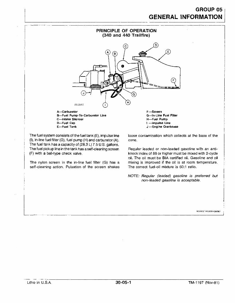
A-CarburetorB-Fuel Pump-To-Carburetor LineC-Intake SilencerD-Fuel CapE-Fuel Tank
The fuel system consists of the fuel tank (E), impulse line(I), in-line fuel filter (G), fuel pump (H)and carburetor (A).The fuel tank has a capacity of (28.3 L) 7.5 U.S. gallons.The fuel pickup line in the tank has a self-cleaningscreen(F) with a ball-type check valve.
The nylon screen in the in-line fuel filter (G) has aself-cleaning action. Pulsation of the screen shakes
F-ScreenG-In-Line Fuel FilterH-Fuel PumpI -Impulse LineJ -Engine Crankcase
loose contamination which collects at the base of thecone.
Regular leaded or non-leaded gasoline with an antiknock index of 88 or higher must be mixed with 2-cycleoil. The oil must be BIA certified oil. Gasoline and oilmixing is improved if the oil is at room temperature.The correct fuel-oil mixture is 50:1 ratio.
NOTE: Regular (leaded) gasoline is preferred butnon-leaded gasoline is acceptable.
M23563/1197/3005A/240981
Litho in U.S.A. 30u05-1 TM-1197 (Nov-81)
General Information
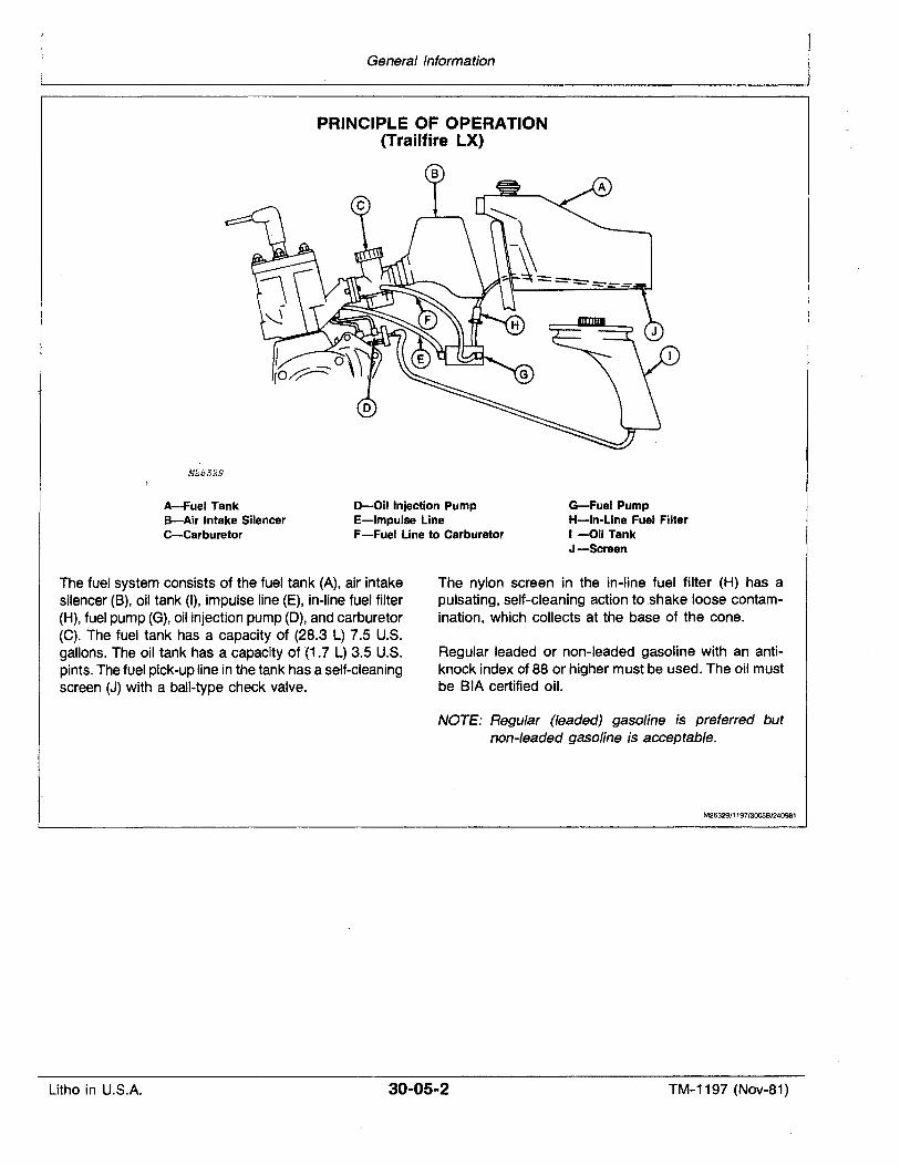
PRINCIPLE OF OPERATION(Trailfire LX)
M25329
A-Fuel TankB-Air Intake SilencerC-Carburetor
D-Oil Injection PumpE-Impulse LineF-Fuel Line to Carburetor
G-Fuel PumpH-In-Line Fuel FilterI-Oil TankJ-Screen
The fuel system consists of the fuel tank (A), air intakesilencer (8), oil tank (I), impulse line (E), in-line fuel filter(H), fuel pump (G), oil injection pump (0), and carburetor(C). The fuel tank has a capacity of (28.3 L) 7.5 U.S.gallons. The oil tank has a capacity of '(1.7 L) 3.5 U.S.pints. The fuel pick-up line in the tank has a self-cleaningscreen (J) with a ball-type check valve.
The nylon screen in the in-line fuel filter (H) has apulsating, self-cleaning action to shake loose contamination, which collects at the base, of the cone.
Regular leaded or non-leaded gasoline with an antiknock index of 88 or higher must be used. The oil mustbe BIA certified oil.
NOTE: Regular (leaded) gasoline is preferred butnon-leaded gasoline is acceptable.
M25329/1197/3005B/240981
Litho in U.S.A. 30-05-2 TM-1197 (Nov-81)
General Information
CARBURETOR
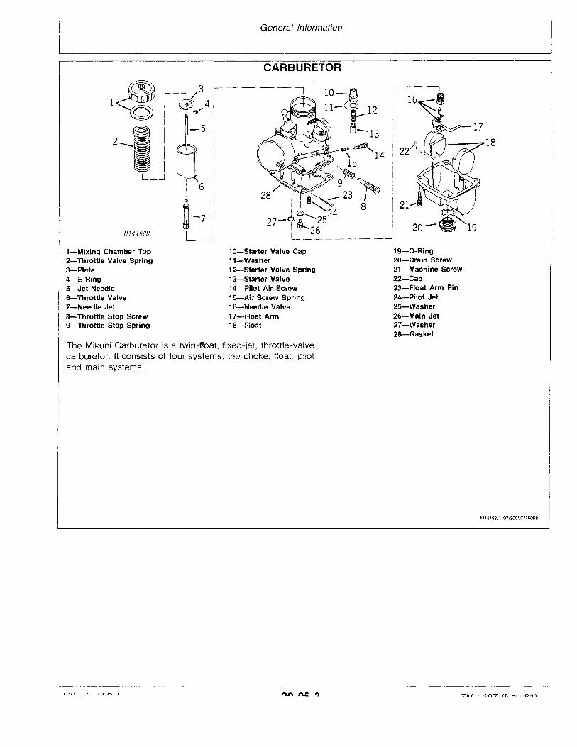
1-Mixing Chamber Top2-Throttle Valve Spring3-Plate4-E..Ring5-Jet Needle6-Throttle Valve7-Needle Jet8-Throttle Stop Screw9-Throttle Stop Spring
10-Starter Valve Cap11-Washer12-Starter Valve Spring13-Starter Valve14-Pilot Air Screwis-AiL'' Screw Spring16-Needle Valve17-Float Arm18-Float
19-0-Ring20-Drain Screw21-Machine Screw22-Cap23-Float Arm Pin24-Pilot Jet25-Washer26-Main Jet27-Washer28-Gasket
The Mikuni Carburetor is a twin-float} fixed-let, throttle-valvecarburetor. It consists of four systems; the choke, float, pilotand main systems.
M144B8/1197/3005C/160981
General Information
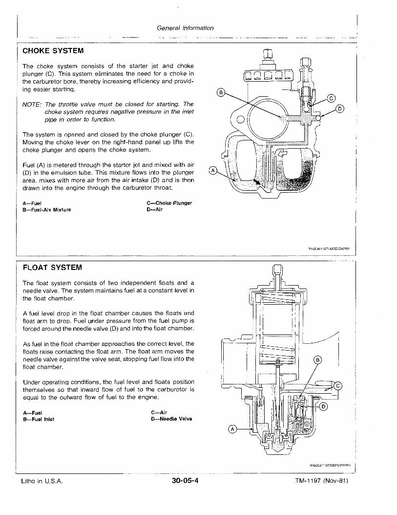
CHOKE SYSTEM
The choke system consists of the starter jet and chokeplunger (C). This system eliminates the need for a choke inthe carburetor bore, thereby increasing efficiency and providing easier starting.
NOTE: The throttle valve must be closed for starting. Thechoke system requires negative pressure in the inletpipe in order to function.
The system is opened and closed by the choke plunger (C).Moving the choke lever on the right-hand panel up lifts thechoke plunger and opens the choke system.
Fuel (A) is metered through the starter jet and mixed with air(0) in the emulsion tube. This mixture flows into the plungerarea, mixes with more air from the air intake (0) and is thendrawn into the engine through the carburetor throat.
A-FuelB-Fuel-Aix Mixture
C-Choke PlungerD-Air
M18208/1197/3005D/240981
The float system consists of two independent floats and aneedle valve. The system maintains fuel at a constant level inthe float chamber.
A fuel level drop in the float chamber causes the floats andfloat arm to drop. Fuel under pressure from the fuel pump isforced around the needle valve (0) and into the float chamber.
Under operating conditions, the fuel level and floats positionthemselves so that inward flow of fuel to the carburetor isequal to the outward flow of fuel to the engine.
C-AirD-Needle Valve
A-FuelB-Fuel Inlet
FLOAT SYSTEM
As fuel in the float chamber approaches the correct level, thefloats raise contacting the float arm. The float arm moves theneedle valve against the valve seat, stopping fuel flow into thefloat chamber.
M18209/1197/3005E/240981
Litho in U.S.A. 30-05-4 .TM-1197 (Nov-81)
General Information
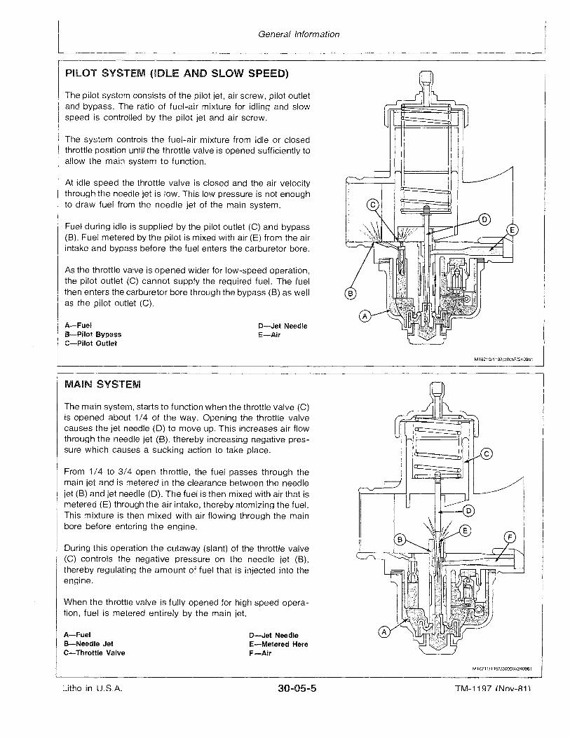
PILOT SYSTEM (IDLE AND SLOW SPEED)
Fuel during idle is supplied by the pilot outlet (C) and bypass(8). Fuel metered by the pilot is mixed with air (E) from the airintake and bypass before the fuel enters the carburetor bore.
The system controls the fuel-air mixture from idle or closedthrottle position until the throttle valve is opened sufficiently toallow the main system to function.
D-Jet NeedleE-Air
A-FuelB-Pilot BypassC-Pilot Outlet
At idle speed the throttle valve is closed and the air velocitythrough the needle jet is low. This low pressure is not enoughto draw fuel from the needle jet of the main system.
As the throttle valve is opened wider for low-speed operation,the pilot outlet (C) cannot supply the required fuel. The fuelthen enters the carburetor bore through the bypass (8) as wellas the pilot outlet (C).
The pilot system consists of the pilot jet, air screw, pilot outletand bypass. The ratio of fuel-air mixture for idling and slowspeed is controlled by the pilot jet and air screw.
M18210/1197/3005F/240981
When the throttle valve is fully opened for high speed operation, fuel is metered entirely by the main jet.
During this operation the cutaway (slant) of the throttle valve(C) controls the negative pressure on the needle jet (8),thereby regulating the amount of fuel that is injected into theengine.
The main system, starts to function when the throttle valve (C)is opened about 1/4 of the way. Opening the throttle valvecauses the jet needle (D) to move up. This increases air flowthrough the needle jet (8), thereby increasing negative pressure which causes a sucking action to take place.
D-Jet NeedleE-Metered HereF-Air
MAIN SYSTEM
From 1/4 to 3/4 open throttle, the fuel passes through themain jet and is metered in the clearance between the needlejet (B) and jet needle (D). The fuel is then mixed with air that ismetered (E) through the air intake, thereby atomizing the fuel.This mixture is then mixed with air flowing through the mainbore before entering the engine.
A-FuelB-Needle JetC-Throttle Valve
M18211/1197/3005G/240981
Litho in U,S.A. 30...05-5 TM-11 ~7 (Nov-Ai)
CARBURETOR TOO RICH
General Information
DIAGNOSE MALFUNCTIONS
CARBURETOR TOO LEAN
Float level incorrect.Dirt under inlet needle valve.Silencer restricted.Wrong main jet.Choke system adjusted incorrectly.Jet needle clip positioned incorrectly.Air jet restricted.
In-line fuel filter plugged or restricted.Dirty fuel pickup strainer in fuel tank.Fuel pump impulse line plugged.Hole in fuel impulse line.Jet needle clip positioned incorrectly.Wrong main jet.Faulty fuel pump.Pinched fuel lines.Hole in intake silencer boot.Head gasket leaking.Operating with air intake silencer removed.Air leakage at intake manifold gaskets.Air leakage at crankshaft seals or crankcase mating
surfaces.Jnlet needle valve restricted.
1197/3005H/240981
Litho in U.S.A. 30-05-6 TM-1197 (Nov-81)
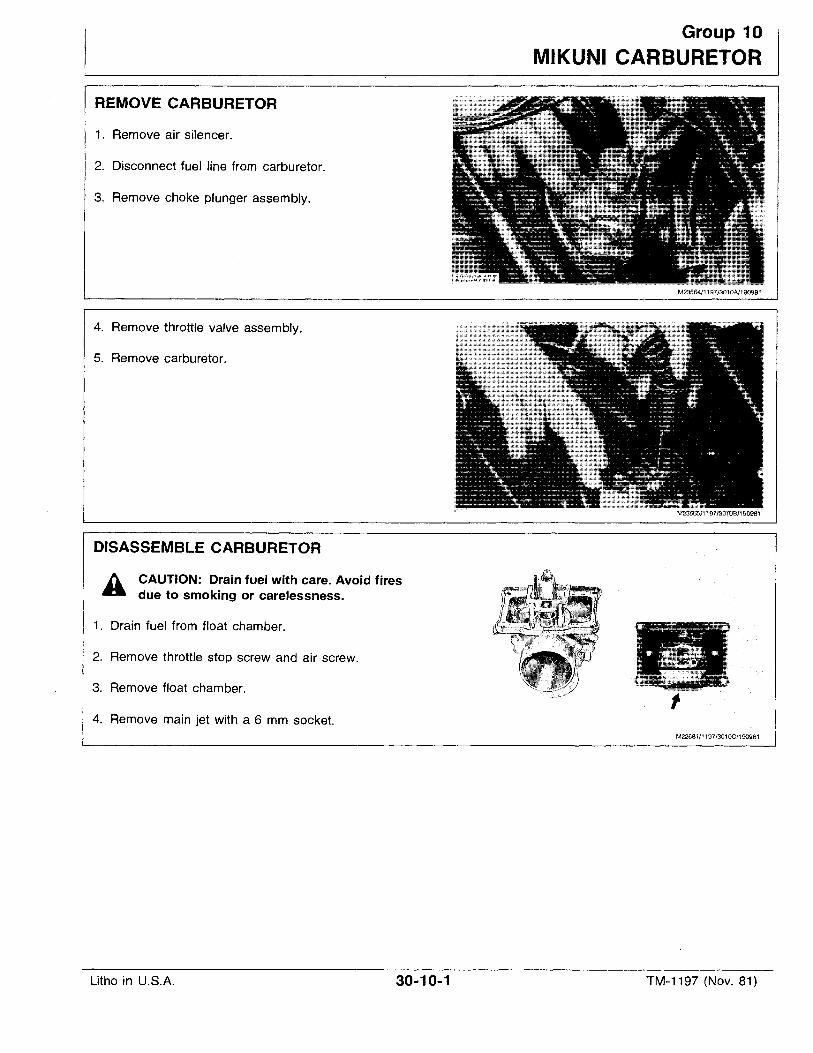
REMOVE CARBURETOR
1. Remove air silencer.
2. Disconnect fuel .line from carburetor.
3. Remove choke plunger assembly.
4. Remove throttle valve assembly.
5. Remove carburetor.
DISASSEMBLE CARBURETOR
h CAUTION: Drain fuel with care. Avoid firesa due to smoking or carelessness.
1. Drain fuel from float chamber.
2. Remove throttle stop screw and air screw.
3. Remove float chamber.
4. Remove main jet with a 6 mm socket.
Group 10
MIKUNI CARBURETOR
M23564/1197/3010A/190981
M23565/1197/3010B/190981
M22681/1197/3010C/190981
Litho in U.S.A. 30-10-1 TM-1197 (Nov. 81)
Mikuni Carburetor
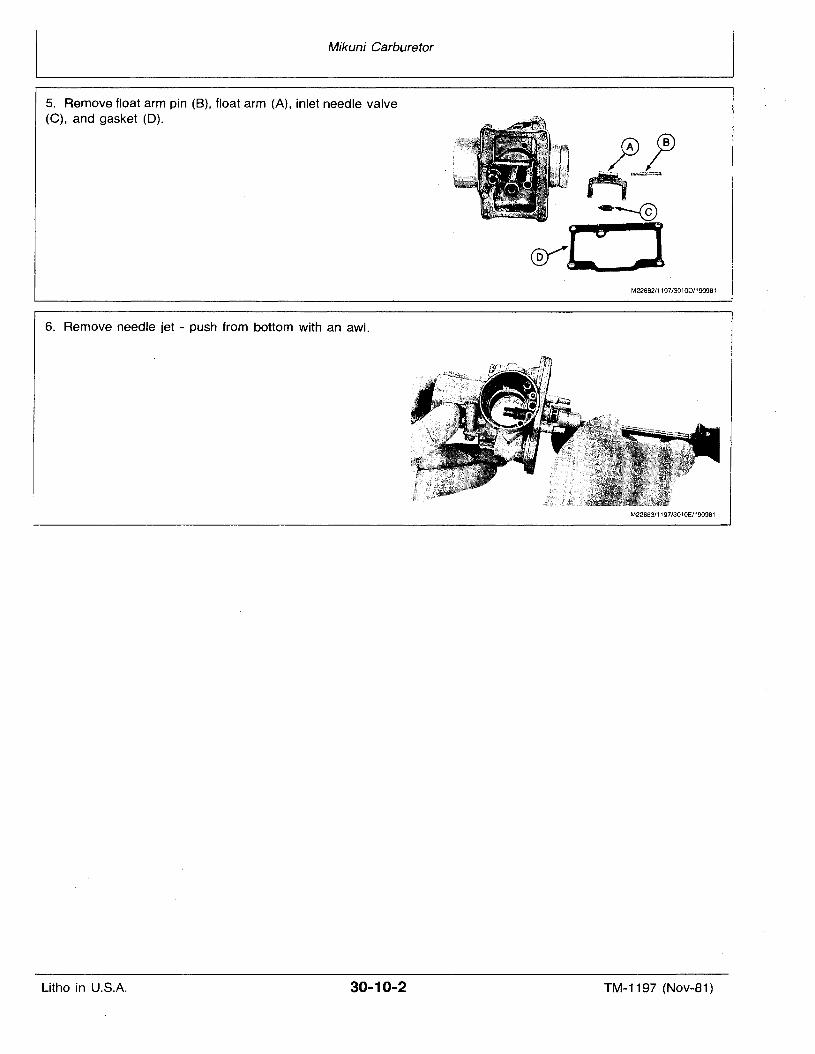
5. Remove float arm pin (B), float arm (A), inlet needle valve(C), and gasket (D).
6. Remove needle jet - push from bottom with an awl.
M22682/1197/301OD/190981
M22683/1197/3010E/190981
Litho in U.S.A. 30-10-2 TM-1197 (Nov-81)
Mikuni Carburetor
INSPECT AND REPAIR CARBURETOR
IMPORTANT: Never clean jets or passages with smalldrills or wire. Replace jets if varnished.
1. Place carburetor parts except gaskets in PT503 Cleaner orequivalent for 1 to 2 hours.
2. Rinse parts in solvent.
IMPORTANT: Do not use rags or paper to dry parts - lintmay plug jets, passages.
3. Dry parts with compressed air, be sure all holes are open.
4. Rinse mixing chamber body and float chamber in hot waterto stop cleaner action on aluminum.
5. Check mixing chamber body, float chamber for cracks ordamage.
6. Check all springs for damage or distortion.
7. Check throttle stop screw, set screw for damage to seatingsurface or stripped threads.
8. Check main, pilot jets for damage or stripped threads.
NOTE: Jets must be clean, shiny. Abrasives cause leanfuel-air mixture, possible engine damage.
9. Remove retainer and inlet valve, check seat and seatsurface of valve for damage.
NOTE: Make sure retainer does not hinder motion of inletvalve.
10. Check jet and needle for damage; needle should slidefreely.
11. Install float, move up and down - they should not bind onguides.
12. Check that float arm does not bind on pin.
13. Check that choke plunger moves freely.
14. Install throttle valve, check for sticking.
15. Check that guide pin is not broken - this allows throttle1197/301OF/19Q981
ASSEMBLE CARBURETOR
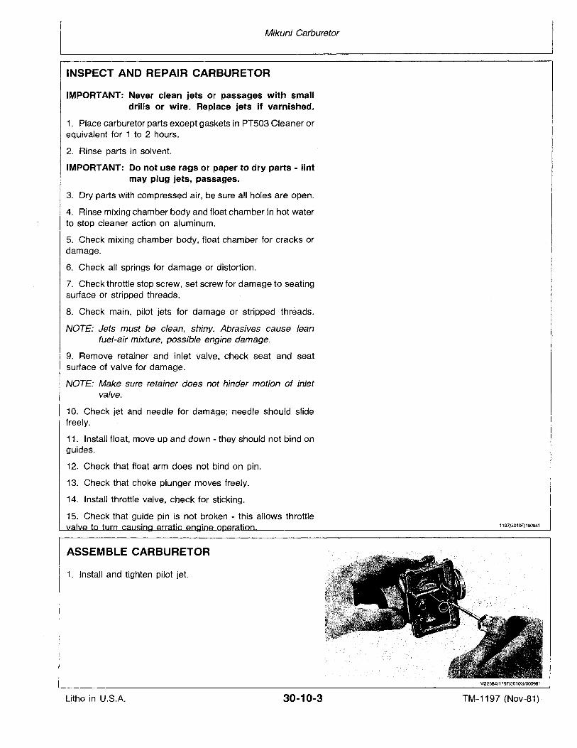
1. Install and tighten pilot jet.
M22684/1197/301OG/000981
Litho in U.S.A. 30-10-3 TM-1197 (Nov-81)
Mikuni Carburetor
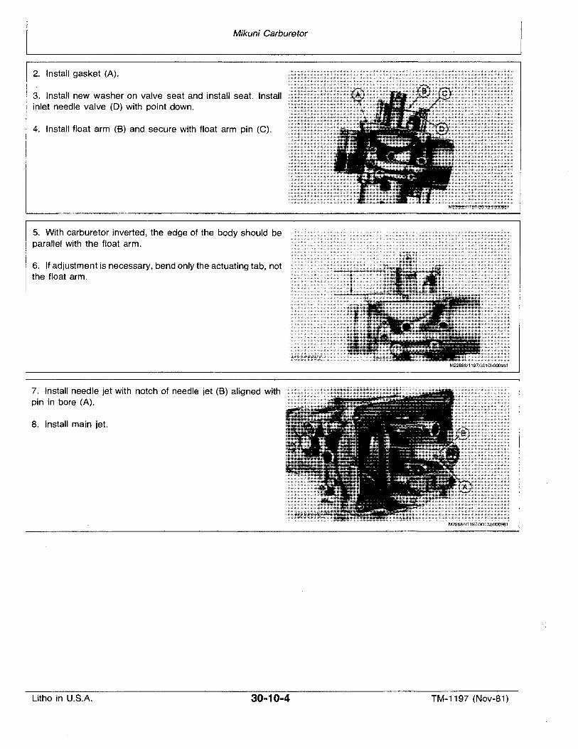
2. Install gasket (A).
3. Install new washer on valve seat and install seat. Installinlet needle valve (0) with point down.
4. Install float arm (B) and secure with float arm pin (C).
5. With carburetor inverted, the edge of the body should beparallel with the float arm.
6. If adjustment is necessary, bend only the actuating tab, notthe float arm.
7. Install needle jet with notch of needle jet (B) aligned withpin in bore (A).
8. Install main jet.
M22686/1197/30101/0009B1
M226B7/1197/301OJ/000981
Litho in U.S.A. 30-10-4 TM-1197 (Nov-81)
Mikuni Carburetor
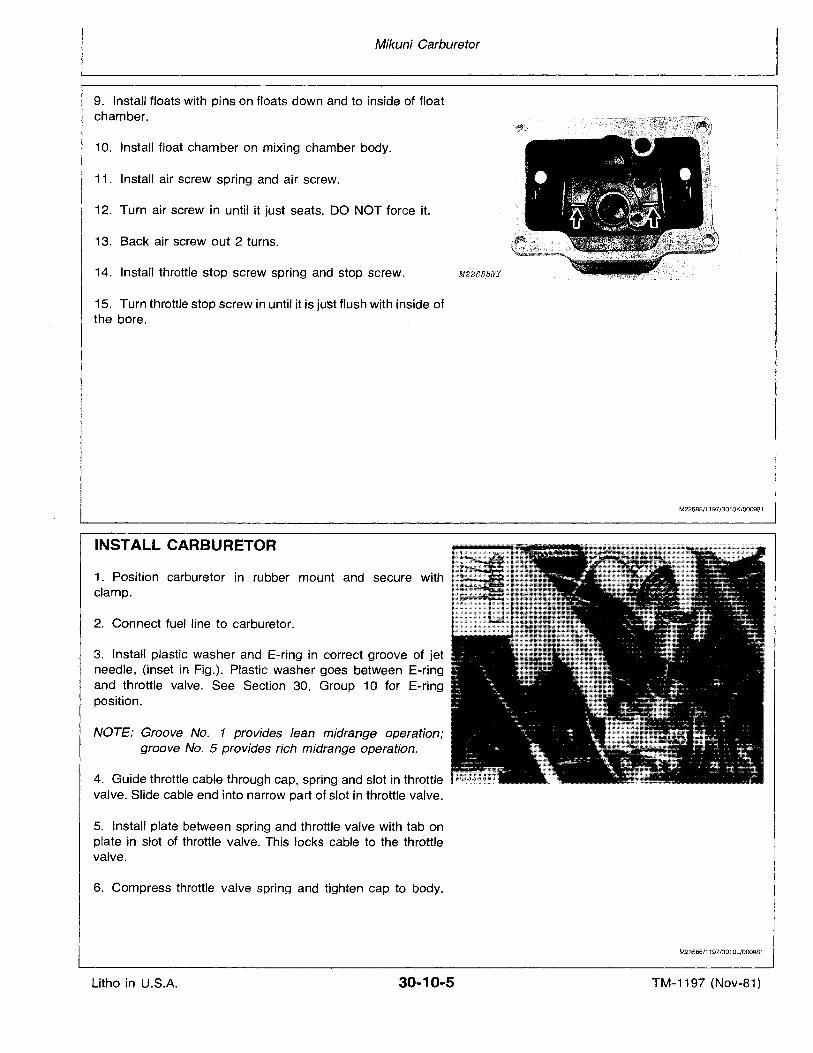
9. Install floats with pins on floats down and to inside of floatchamber.
10. Install float chamber on mixing chamber body.
11. Install air screw spring and air screw.
12. Turn air screw in until it just seats. DO NOT force it.
13. Back air screw out 2 turns.
14. Install throttle stop screw spring and stop screw.
15. Turn throttle stop screw in until it is just flush with inside ofthe bore.
M2.?688NY
M22688/1197/3010K/000981
INSTALL CARBURETOR
1. Position carburetor in rubber mount and secure withclamp.
2. Connect fuel line to carburetor.
3. Install plastic washer and E-ring in correct groove of jetneedle, (inset in Fig.). Plastic washer goes between E-ringand throttle valve. See Section 30, Group 10 for E-ringposition.
NOTE: Groove No. 1 provides lean midrange operation;groove No. 5 provides rich midrange operation.
4. Guide throttle cable through cap, spring and slot in throttle IM23b66!1.Y
valve. Slide cable end into narrow part of slot in throttle valve.
5. Install plate between spring and throttle valve with tab onplate in slot of throttle valve. This locks cable to the throttlevalve.
6. Compress throttle valve spring and tighten cap to body.
M23566/1197/3010L/000981
Litho in U.S.A. 30-10-5 TM-1197 (Nov-81)
Mikuni Carburetor
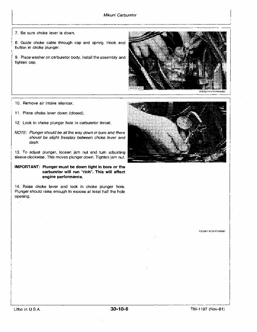
7. Be sure choke lever is down.
8:~. Guide choke cable through cap and spring. Hook endbutton in choke plunger.
9. Place washer on carburetor body. Install the assembly andtighten cap.
10. Remove air intake silencer.
11. Place choke lever down (closed).
12. Look in choke plunger hole in carburetor throat.
NOTE: Plunger should be all the way down in bore and thereshould be slight freep/ay between choke lever anddash.
13. To adjust plunger, loosen jam nut and turn adjustingsleeve clockwise. This moves plunger down. Tighten jam nut.
IMPORTANT: Plunger must be down tight in bore or thecarburetor will run "rich". This will affectengine performance.
14. Raise choke lever and look in choke plunger hole.Plunger should raise enough to expose at least half the holeopening.
M23564/1197/3010M/000981
M23306/1197/3010N/000981
Litho in U.S.A. 30-10-6 TM-1197 (Nov-81)
Mikuni Carburetor
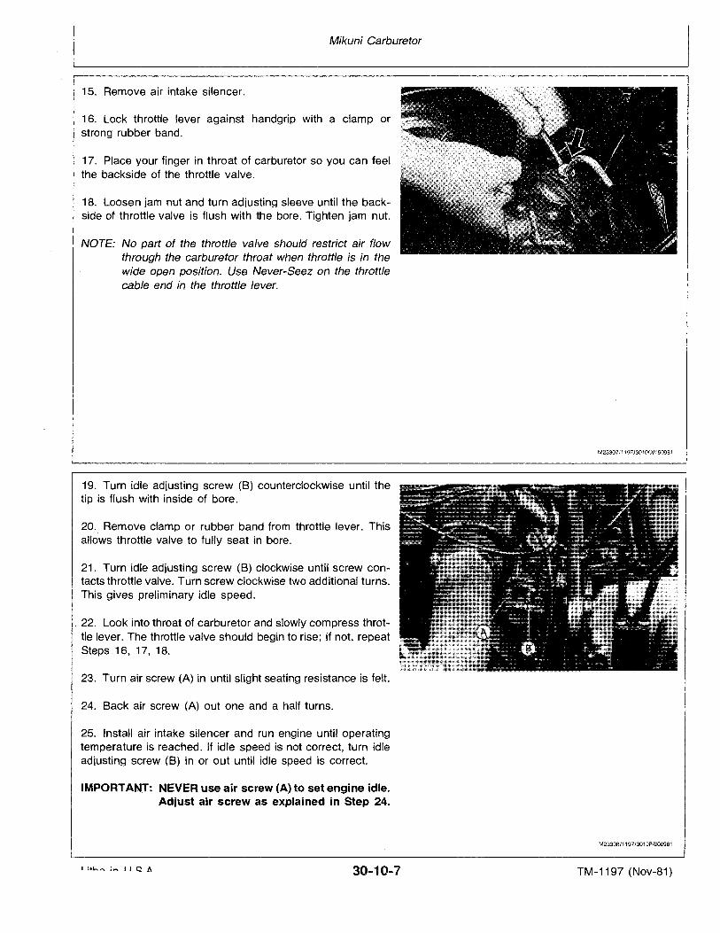
15. Remove air intake silencer.
16. Lock throttle lever against handgrip with a clamp orstrong rubber band.
17. Place your finger in throat of carburetor so you can feelthe backside of the throttle valve.
18. Loosen jam nut and turn adjusting sleeve until the backside of throttle valve is flush with the bore. Tighten jam nut.
NOTE: No part of the throttle valve should restrict air flowthrough the carburetor throat when throttle is in thewide open position. Use Never-Seez on the throttlecable end in the throttle lever.
19. Turn idle adjusting screw (B) counterclockwise until thetip is flush with inside of bore.
20. Remove clamp or rubber band from throttle lever. Thisallows throttle valve to fully seat in bore.
21. Turn idle adjusting screw (B) clockwise until screw contacts throttle valve. Turn screw clockwise two additional turns.This gives preliminary idle speed .
. 22. Look into throat of carburetor and slowly compress throttle lever. The throttle valve should begin to rise; if not, repeatSteps 16, 17, 18.
23. Turn air screw (A) in until slight seating resistance is felt.
24. Back air screw (A) out one and a half turns.
25. Install air intake silencer and run engine until operatingtemperature is reached. If idle speed is not correct, turn idleadjusting screw (B) in or out until idle speed is correct.
IMPORTANT: NEVER use air screw (A) to set engine idle.Adjust air screw as explained in Step 24.
M23307/1197/30100/160981
M2330B/1197/3010P/000981
30-10-7 TM-1197 (Nov-81)
Carburetor
Temperature
Below (-18°C) O°F
Above (-18°C) O°F
ALLTEMPERATURES
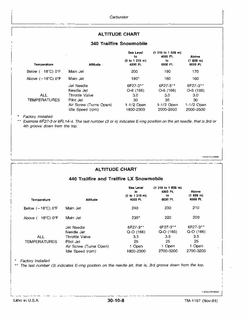
ALTITUDE CHART
340 Trailfire Snowmobile
Sea Level (1 219 to 1 828 m)to 4000 Ft. Above
(0 to 1 219 m) to (1 828 m)Altitude 4000 -:=t. 6000 Ft. 6000 Ft.
Main Jet 200 190 170
'Main Jet 190* 180 160
Jet Needle 6F27-3** 6F27-3** 6F27-3**Needle Jet 0-6 (166) 0-6 (166) 0-6 (166)Throttle Valve 3.0 3.0 3.0Pilot Jet 30 30 30Air Screw (Turns Open) 1-1/2 Open 1-1/2 Open 1-1/2 OpenIdle Speed (rpm) 1800-2300 2000-2500 2000-2500
* Factory Installed** Example 6F27-3 or 6FL 14-4. The last number (3 or 4) indicates E-ring position on the jet needle, that is 3rd or
4th groove down from the top.
1197/30100/000981
ALTITUDE CHART
440 Trailfire and Trailfire LX Snowmobile
Temperature
ALLTEMPERATURES
Sea Level (1 219 to 1 828 m)to 4000 Ft. Above
(0 to 1 219 m) to (1 828 m)Altitude 4000 Ft. 6000 Ft. 6000 Ft.
Main Jet 240 230 210
Main Jet 230* 220 200
Jet Needle 6F27-3** 6F27-3** 6F27-3**Needle Jet 0-0 (166) 0-0 (166) 0-0 (166)
Throttle Valve 3.5 3.5 3.5
Pilot Jet 25 25 25Air Screw (Turns Open) 1 Open 1 Open 1 OpenIdle Speed (rpm) 1800-2300 2700-3200 2700-3200
* Factory Installed** The last number (3) indicates E-ring position on the needle jet, that is, 3rd groove down from the top.
11Q7/3010R/000981
Litho in U.S.A. 30-10-8 TM-1197 (Nov-81)
Group 15FUEL PUMP, FUEL TANK, SCREEN AND
IN-LINE FUEL FILTER
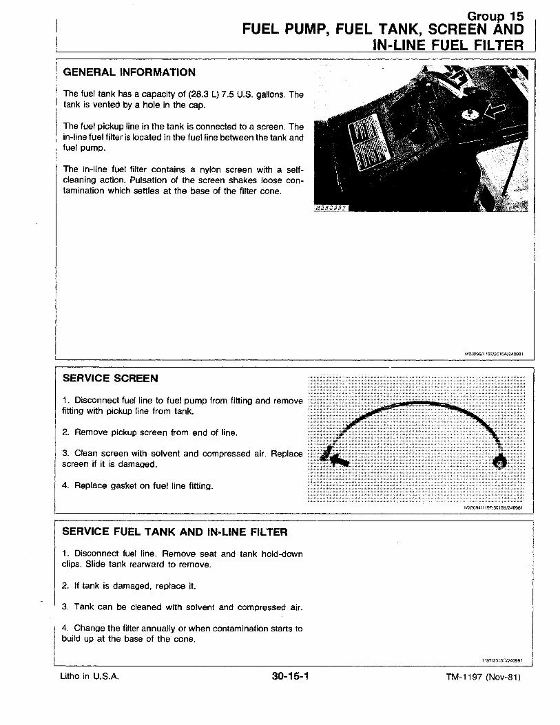
GENERAL INFORMATION
The fuel tank has a capacity of (28.3 L) 7.5 U.S. gallons. Thetank is vented by a hole in the cap.
The fuel pickup line in the tank is connected to a screen. Thein-line fuel filter is located in the fuel line between the tank andfuel pump.
The in-line fuel filter contains a nylon screen with a selfcleaning action. Pulsation of the screen shakes loose contamination which settles at the base of the filter cone.
M2329911197/3015A/240981
SERVICE SCREEN
1. Disconnect fuel line to fuel pump from fitting and removefitting with pickup line from tank.
2. Remove pickup screen from end of line.
3. Clean screen with solvent and compressed air. Replacescreen if it is damaged.
4. Replace gasket on fuel line fitting.
M22694/1197/3015B/240981
SERVICE FUEL TANK AND IN-LINE FILTER
1. Disconnect fuel line. Remove seat and tank hold-downclips. Slide tank rearward to remove.
2. If tank is damaged, replace it.
3. Tank can be cleaned with solvent and compressed air.
4. Change the filter annually or when contamination starts tobuild up at the base of the cone.
i 197/3015C/240981
Litho in U.S.A. 30-15-1 TM-1197 (Nov-81)
Fuel Pump, Fuel Tank, Screen and In-Line Fuel Filter
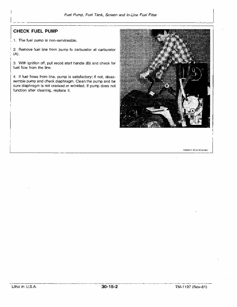
CHECK FUEL PUMP
1. The fuel pump is non-serviceable.
2. Remove fuel line from pump to carburetor at carburetor(A).
3. With ignition off, pull recoil start handle (B) and check forfuel flow from the line.
4. If fuel flows from line, pump is satisfactory; if not, disassemble pump and check diaphragm. Clean the pump and besure diaphragm is not cracked or wrinkled. If pump does notfunction after cleaning, replace it.
M29287/1197/3015D/240981
Litho in U.S.A. 30-15-2 TM-1197 (Nov-81)
Group 20
OIL INJECTION SYSTEM
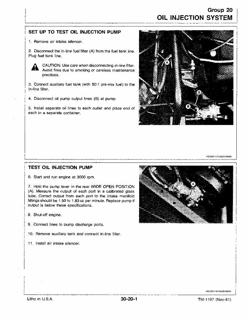
1. Remove air intake silencer.
4. Disconnect oil pump output lines (B) at pump.
SET UP TO TEST OIL INJECTION PUMP
CAUTION: Use care when disconnecting in-line filter.Avoid fires due to smoking or careless maintenancepractices.
A
2. Disconnect the in-line fuel filter (A) from the fuel tank line.Plug fuel tank line.
3. Connect auxiliary fuel tank (with 50:1 pre-mix fuel) to thein-fine filter.
5. Install separate oil lines to each outlet and place end ofeach in a separate container.
M29288/1197/3020A/000981
TEST OIL INJECTION PUMP
6. Start and run engine at 3000 rpm.
7. Hold the pump lever in the rear WIDE OPEN POSITION(A). Measure the output of each port in a calibrated glasstube. Correct output from each port to the intake manifoldfittings should be 1.50 to 1.83 cc per minute. Replace pump ifoutput is below these specifications.
8. Shut-off enqlne,
9. Connect lines to pump discharge ports.
10. Remove auxiliary tank and connect in-line filter.
11. Install air intake silencer.
M29289/1197/3020B/000981
Litho in U.S.A. 30-20-1 TM-1197 (Nov-81)
Oil Injection System
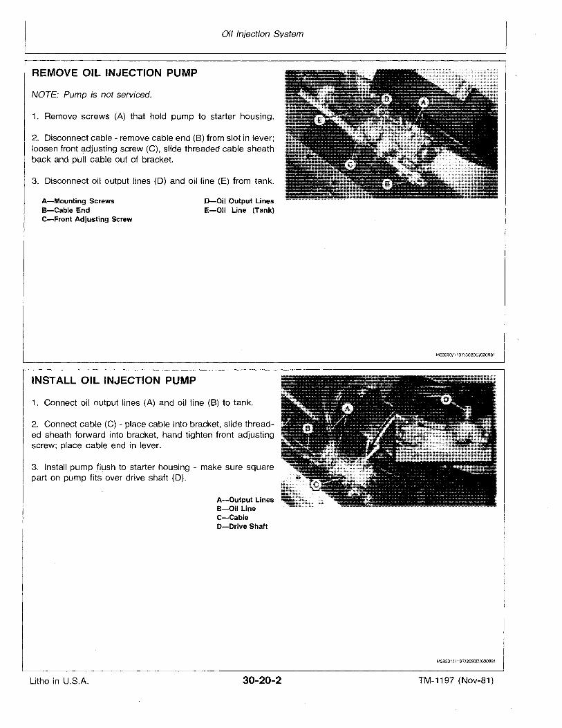
NOTE: Pump is not serviced.
3. Disconnect oil output lines (D) and oil line (E) from tank.
1. Remove screws (A) that hold pump to starter housing.
D-Oil Output LinesE-Oil Line (Tank)
A-Mounting ScrewsB-Cable EndC-Front Adjusting Screw
2. Disconnect cable - remove cable end (B) from slot in lever;loosen front adiustinq screw (C), slide threaded cable sheathback and pull cable out of bracket.
REMOVE OIL INJECTION PUMP
M29290/1197/3020C/OOO981
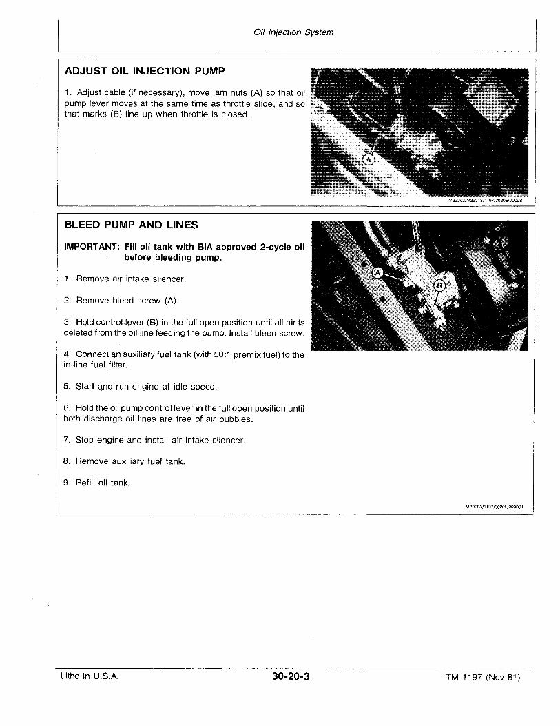
INSTALL OIL INJECTION PUMP
1. Connect oil output lines (A) and oil line (8) to tank.
2. Connect cable (C) - place cable into bracket, slide threaded sheath forward into bracket, hand tighten front adjustingscrew; place cable end in lever.
3. Install pump' flush to starter housing - make sure squarepart on pump fits over drive shaft (D).
A-Output LinesB-Oil LineC-CableD-Drive Shaft
M29291/1197/3020D/OOO981
Litho in U.S.A. 30-20-2 TM-1197 (Nov-81)
Oil Injection System
ADJUST OIL INJECTION PUMP
1. Adjust cable (if necessary), move jam nuts (A) so that oilpump lever moves at the same time as throttle slide, and sothat marks (8) line up when throttle is closed.
BLEED PUMP AND LINES
IMPORTANT: Fill oil tank with BIA approved 2-cycle oilbefore bleeding pump.
1. Remove air intake silencer.
2. Remove bleed screw (A).
3. Hold control ,lever (B) in the full open position until all air isdeleted from the oiJ line feeding the pump. Install bleed screw.
4. Connect anauxiliary fuel tank (with 50:1 premix fuel) to thein-line fuel filter.
5. Start and run engine at idle speed.
6. Hold the oil pump control lever in the full open position untilboth discharge oil lines are free of air bubbles.
7. Stop engine and install air intake silencer.
8. Remove auxiliary fuel tank.
9. Refill oil tank.
M29293/1197/3020F/OOO981
Litho in U.S.A. 30-20-3 TM-1197 (Nov-81) .

Litho in U.S.A.
Oil Injection System
30-20-4 TM-1197 (Nov-81)
Section 40ELECTRICAL SYSTEM
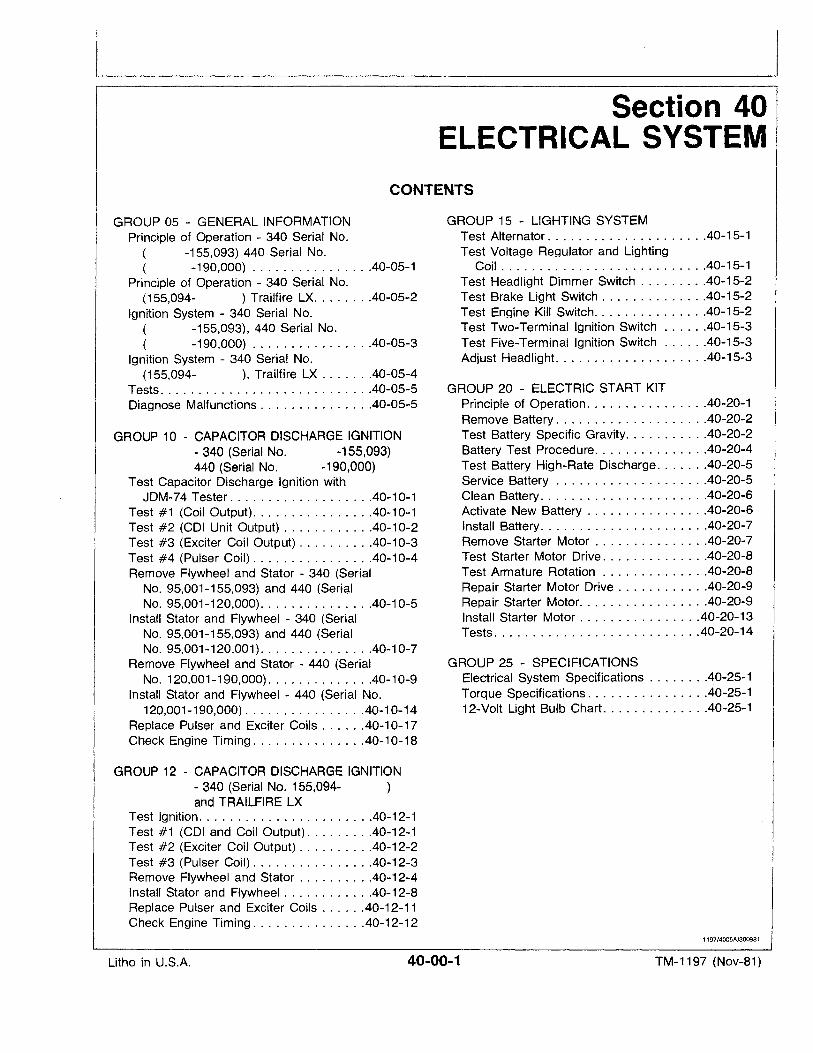
CONTENTS
GROUP 05· - GENERAL INFORMATIONPrinciple of Operation - 340 Serial No.
( -155,093) 440 Serial No.( -190,000) 40-05-1
Principle of Operation - 340 Serial No.(155,094- ) Trailfire LX 40-05-2
Ignition System - 340 Serial No.( -155,093), 440 Serial No.( -190,000) 40-05-3
Ignition System - 340 Serial No.(155,094- ), Trailfire LX 40-05-4
Tests 40-05-5Diagnose Malfunctions 40-05-5
GROUP 10 - CAPACITOR DISCHARGE IGNITION- 340 (Serial No. -155,093)440 (Serial No. -190,000)
Test Capacitor Discharge Ignition withJDM-74 Tester 40-10-1
Test #1 (Coil Output) 40-10-1Test #2 (COl Unit Output) 40-10-2Test #3 (Exciter Coil Output) 40-10-3Test #4 (Pulser Coil) 40-10-4Remove Flywheel and Stator - 340 (Serial
No. 95,001-155,093) and 440 (SerialNo. 95,001-120,000) 40-10-5
Install Stator and Flywheel - 340 (SerialNo. 95,001-155,093) and 440 (SerialNo. 95,001-120,001) 40-10-7
Remove Flywheel and Stator - 440 (SerialNo. 120,001-190,000) 40-10-9
Install Stator and Flywheel - 440 (Serial No.120,001-190,000) 40-10-14
Replace Pulser and Exciter Coils 40-10-17Check Engine Timing 40-10-18
GROUP 12 - CAPACITOR DISCHARGE IGNITION- 340 (Serial No. 155,094- )and TRAILFIRE LX
Test Ignition. . . . . . . . . . . . . . 40-12-1Test #1 (COl and Coil Output) 40-12-1Test #2 (Exciter Coil Output) 40-12-2Test #3 (Pulser Coil) 40-12-3Remove Flywheel and Stator 40-12-4Install Stator and Fly.wheel 40-12-8Replace Pulser and Exciter Coils 40-12-11Check Engine Timing 40-12-12
GROUP 15 - LIGHTING SYSTEMTest Alternator. . . . . . . . . . . . . . . . . . . . .40-15-1Test Voltage Regulator and Lighting
Coil 40-15-1-Test Headlight Dimmer Switch 40-15-2Test Brake Light Switch 40-15-2Test Engine Kill SWitch 40-15-2Test Two-Terminal Ignition Switch 40-15-3Test Five-Terminal Ignition Switch 40-15-3Adjust Headlight 40-15-3
GROUP 20 - ELECTRIC START KITPrinciple of Operation. . . . . . . . . . . . . . . .40-20-1Remove Battery 40-20-2Test Battery Specific Gravity 40-20-2Battery Test Procedure 40-20-4Test Battery High-Rate Discharge 40-20-5Service Battery . . . . . . . . . . . . . . . . . . . .40-20-5Clean Battery. . . . . . . . . . . . . . . . . . . . . .40-20-6Activate New Battery 40-20-6Install Battery 40-20-7Remove Starter Motor 40-20-7Test Starter Motor Drive 40-20-8Test Armature Rotation 40-20-8Repair Starter Motor Drive 40-20-9Repair Starter Motor. . . . . . . . . . . . . . . . .40-20-9Install Starter Motor 40-20-13Tests. . . . . . . . . . . . . . . . . . . . . . . . . . .40-20-14
GROUP 25 - SPECIFICATIONSElectrical System Specifications . . . . . . . .40-25-1Torque Specifications 40-25-112-Volt Light Bulb Chart 40-25-1
1197/4005A/300981
Litho in U.S.A. 40-00-1 TM-1197 (Nov-81)

Litho in U.S.A.
Contents
40-00-2 TM-1197 (Nov-81)
Group 05
GENERAL INFORMATION
BLACK
SPEEDOMETER
YElLmJ
GREEN
HEAD LIGHT
H@OW
PINK
BLACK
BLACK
YELLOW
BLACK &WHITE
I~------~~-~BLACK &WHITEWHITE~ ~~BLACK YELLOW~~1f~GREEN ~TAN~ PINK'~ ORANGE~
KILL SWITCH HI-LOW BEAM BRAKE LIGHTCLOSED OPEN CLOSED OPEN CLOSED OPENIOFF IA&BI I HI A&B C IOFFI IA&B I
ON - A&B LOW B&C A ON A&B -
IGNITIONCOIL ,-.oro
I ; YELLOW>.J IL_.1~
VOLTAGEREGULATORAM52886
M26337
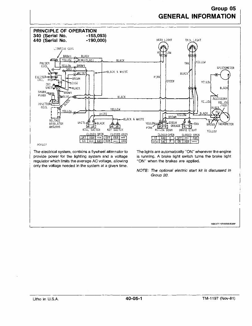
PRINCIPLE OF OPERATION340 (Serial No. -155,093)440 (Serial No. -190,000)
The electrical system, contains a flywheel alternator toprovide power for the lighting system and a voltageregulator which limits the average AC voltage, allowingonly the voltage needed in the system at a given time.
The lights are automatically "ON" whenever the engineis running. A brake light switch turns the brake light"ON" when the brakes are applied.
NOTE: The optional electric stert kit is discussed inGroup 20.
M26337/11974005B/250981
Litho in U.S.A. 40-05-1 TM-1197 (Nov-81)
General Information
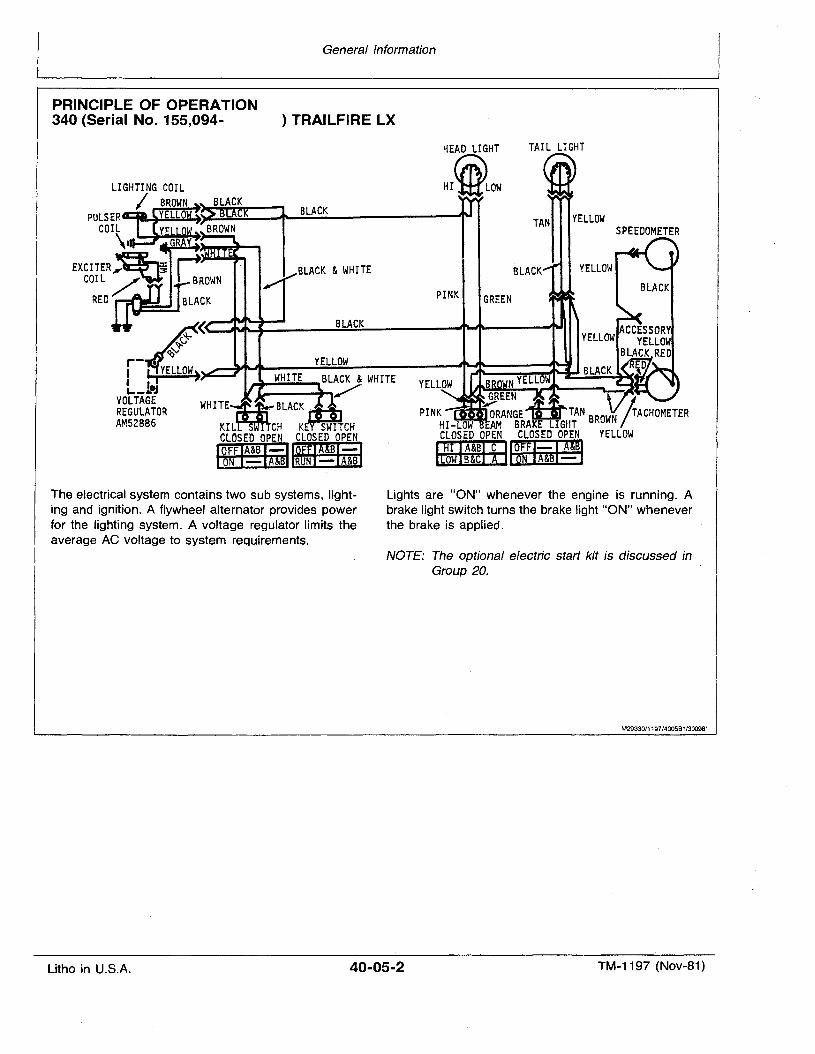
PRINCIPLE OF OPERATION340 (Serial No. 155,094- ) TRAILFIRE LX
SPEEDOMETER
TAIL LIGHT
BLACK
GREEN
HEAD LIGHT
HIiLow
PINK
GREEN:";;RANGEDTAN BROWN r IrACHOMETER
HI-L W AM BRAKE LIGHT / J
CLOSED OPEN CLOSED OPEN YELLOWnrnmm~1r2mEID~
BLACK
BLACK
BLACK &WHITE
~ ~~-Awt~ ~m------'f'-'P----""II
~<Qv
r- •I I YELLOW)I I i'-_....
VOLTAGEREGULATORAM52886
The electrical system contains two sub systems, I,ighting and ignition. A flywheel alternator provides powerfor the lighting system. A voltage regulator limits theaverage AC voltage to system requirements.
Lights are "ON" whenever the engine is running. Abrake light switch turns the brake light "ON" wheneverthe brake is applied.
NOTE: The optional electric start kit is discussed inGroup 20.
M29330/1197/4005B1/300981
Litho in U.S.A. 40-05-2 TM-1197 (Nov-81)
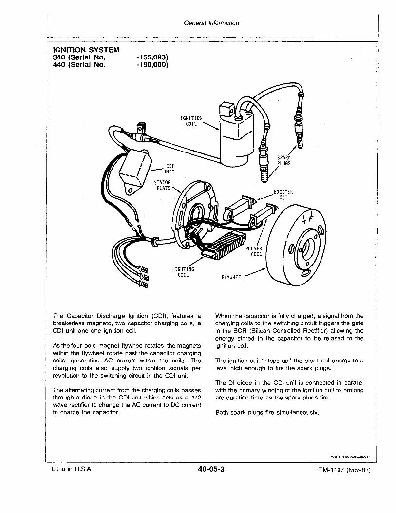
IGNITION SYSTEM340 (Serial No.440 (Serial No.
-155,093)-190,000)
General Information
The Capacitor Discharge Ignition (COl), features abreakerless magneto, two capacitor charging coils, aCOl unit and one ignition coil.
As the four-pole-magnet-flywheel rotates, the magnetswithin the flywheel rotate past the capacitor chargingcoils, generating AC current within the coils. Thecharging coils also supply two igntiion signals perrevolution to the switching circuit in the COl unit.
The alternating current from the charging coils passesthrough a diode in the CDI unit which acts as a 1/2wave rectifier to change the AC current to DC currentto charge the capacitor.
When the capacitor is fully charged, a signal from thecharging coils to the switching circuit triggers the gatein the SCR (Silicon Controlled Rectifier) allowing theenergy stored in the capacitor to be relased to theignition coil.
The ignition coil "steps-up" the electrical energy to alevel high enough to fire the spark plugs.
The 01 diode in the COl unit is connected in parallelwith the primary winding of the ignition coil to prolongarc duration time as the spark plugs fire.
Both spark plugs fire simultaneously.
f\129331J1197400SCJ250981
Litho in U.S.A. 40-05-3 TM-1197 (Nov-81)
General Information
IGNITION SYSTEM340 (Serial No. 155,094- )TRAILFIRE LX
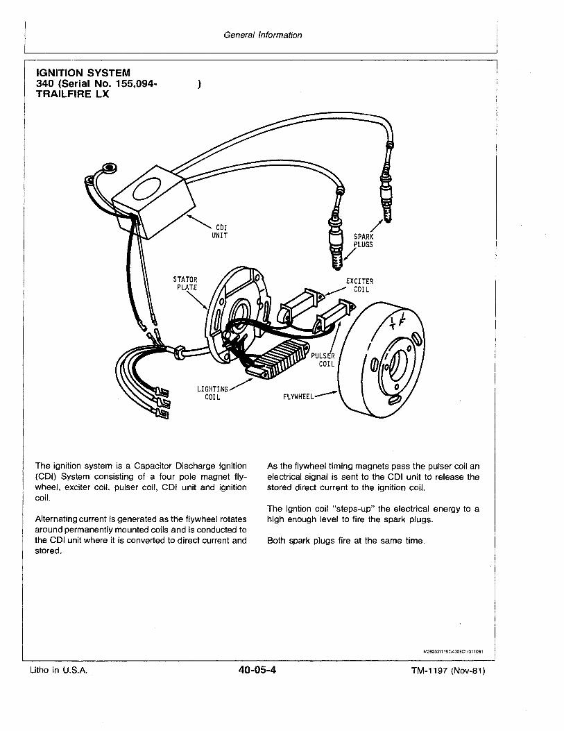
The ignition system is a Capacitor Discharge Ignition(COl) System consisting of a four pole magnet flywheel, exciter coil, pulser coil, COl unit and ignitioncoil.
Alternating current is generated as the flywheel rotatesaround permanently mounted coils and is conducted tothe COl unit where it is converted to direct current andstored.
As the flywheel timing magnets pass the pulser coil anelectrical signal is sent to the COl unit to release thestored direct current to the ignition coil.
The igntion coil "steps-up" the electrical energy to ahigh enough level to fire the spark plugs.
Both spark pluqs fire at the same time.
M29~3211197/4005Cl/011081
Litho in U.S.A. 40-05-4 TM-1197 (Nov-81)
General Information
TESTS
Instructions are provided in each group for testing components. The tests isolate the problem in the lighting or ignitionsystems. _.
High quality test equipment is a must for accurate diagnosis.Always follow the procedures outlined by the equipmentmanufacturer to supplement instructions contained in thismanual.
NOTE: Because there are many manufacturers of testequipment, it is important to follow the manufacturer'srecommendations if the procedures in this manualshould contradict those of the manufacturer.
1197/40050/300981
DIAGNOSE MALFUNCTIONS
Lights Will Not Light
Electric connections loose or wires damaged.Alternator faulty.Bulbs burned out.Voltage regulator faulty.
Brake Light Will Not Light
Brake light switch faulty.Electrical connections loose or wires damaged.Bulb burned out.
Bulbs Burn Out Often
Wrong type bulbs used.Voltage regulator faulty.
Lights Too Bright or Too Dim
Voltage.·regulator faulty.Defective alternator.
Engine Hard To Start
Spark plugs fouled or defective.Engine not. timed properly.Electrical connections loose or corroded.
Engine Misfires
Spark plugs fouled or defective.Electrical connections loose or corroded.Engine not timed properly.
Engine Overheating
Engine not timed properly.
Engine Kicks Back and Backfires
Engine not timed properly,
1197/400sE/300981
Litho in U.S.A. 40-05-5 TM-1197 (Nov-81)

Litho :in U.S.A.
General Information
40-05-6 TM-1197 (Nov-81)
340 (Serial No.
Group 10CAPACITOR DISCHARGE IGNITION (CO'I)
-155,093) and 440 (Serial No. -190,000)
TEST CAPACITOR DISCHARGE IGNITIONWITH JDM-74 TESTER
A CAUTION: Capacitor discharge ignition systemscan produce injurious electrical shock. Alwaysstop engine before touching or working on anyignition components. DO NOT hold spark plugs,leads or connectors in your hand to check forspark.
IMPORTANT: Never use a 12-volt test light on COlor thesystem will be destroyed.
1. Make sure all connections are clean and tight.2. Check all wiring for damage.3. Install new spark plugs.4. Read and understand' all test procedures.5. Perform all tests in sequence.6. Test ignition and kill switches before performing tests onignition. They must be functioning properly.
1197/4010A/280981
TEST #1 (COIL OUTPUT)
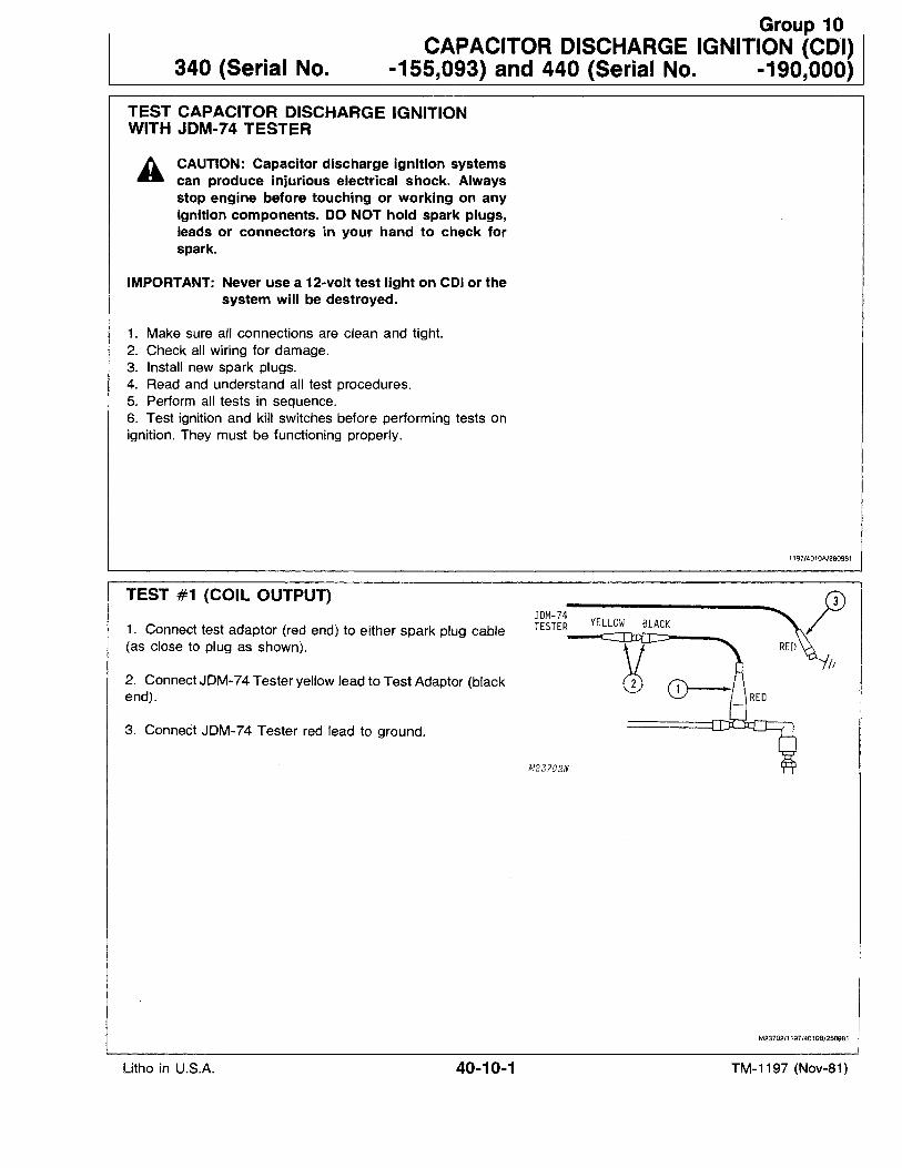
1. Connect test adaptor (red end) to either spark plug cable(as close to plug as shown).
2. Connect JDM-74 Tester yellow lead to Test Adaptor (blackend).
3. Connect JDM-74 Tester red lead to ground.
M23702/1197/401OB/250981
Litho in U.S.A. 40-10-1 TM-1197 (Nov-81)
Capacitor Discharge Ignition (COl) 340 (Serial No.and 440 (Serial No. -190,000)
-155,093)
4. Set tester for "LOW" range.
80
50
10 90
o 100LOWe€) HIGH
20RESET INDICATOR
© 0
5.. Turn tester dial to "25".
7. Crank engine with starter rope and observe tester indicatorlight.
6. Turn key switch "ON" and place emergency stop switch incenter position.
NOTE: If engine starts, allow it to idle while observing indicator. Then, shut engine off.
8. Push reset button and repeat Step 6 twice.
9.. Repeat procedure on remaining spark plug.
Test Results
*Indicator lights on both spark plugs.Ignition system is OK. Remove test leads and check for
other causes.
*Indicator does not light on one or both spark plugs.Remove test leads and proceed to Test #2.
M23703/1197/4010C/250981
TEST #2 (COl UNIT OUTPUT)
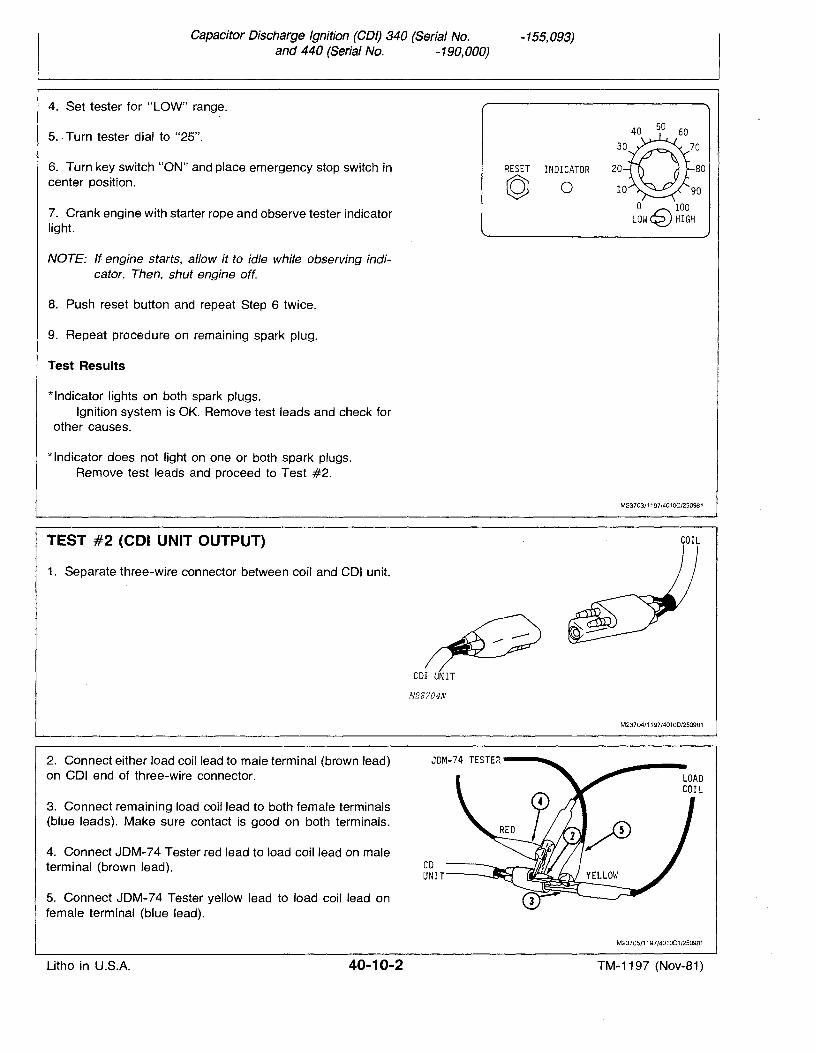
1. Separate three-wire connector between coil and COl unit.
COIL
COl UNIT
M23?04N
M23704/1197/4010D/250981
2. Connect either load coil lead to male terminal (brown lead)on COl end of three-wire connector.
3. Connect remaining load coil lead to both female terminals(blue leads). Make sure contact is good on both terminals.
4. Connect JDM-74 Tester red lead to load coil lead on maleterminal (brown lead).
5. Connect JDM-74 Tester yellow lead to load coil lead onfemale terminal (blue lead).
JDM-74 TESTER ......~
CDUNIT
M2370S/1197/4010D1/250981
Litho in U.S.A. 40-10-2 TM-1197 (Nov-81)
Capacitor Discharge Ignition (CDI) 340 (Serial No.and 440 (Serial No. -190,000)
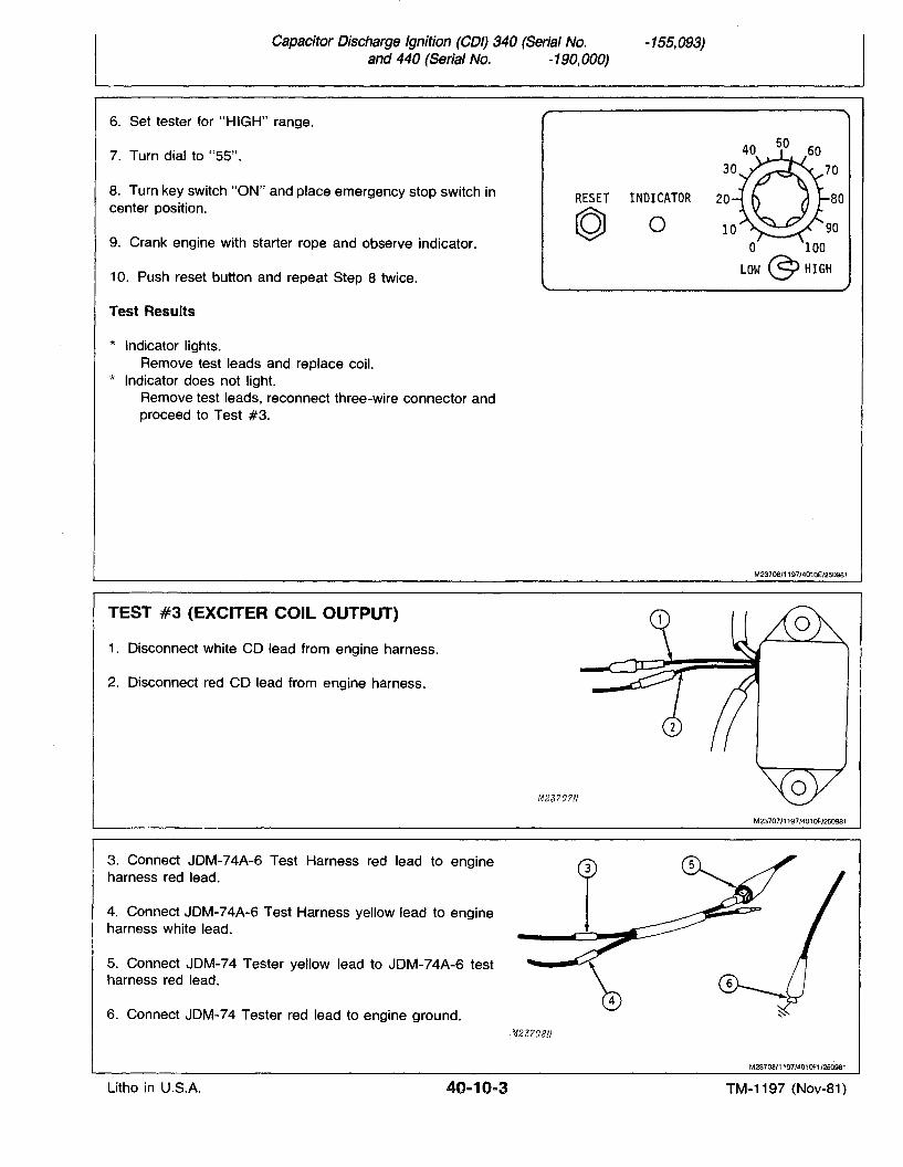
6. Set tester for "HIGH" range.
-155,093)
7. Turn dial to "55".
8. Turn key switch "ON" and place emergency stop switch incenter position.
9. Crank engine with starter rope and observe indicator.
10. Push reset button and repeat Step 8 twice.
Test Results
* Indicator lights.Remove test leads and replace coil.
* Indicator does not light.Remove test leads, reconnect three-wire connector andproceed to Test #3.
RESET INDICATOR
© 0
50
20 80
90o 100
lOW C9 HIGH
M23706/1197/4010E/250981
TEST #3 (EXCITER COIL OUTPUT)
1. Disconnect white CD lead from engine harness.
2. Disconnect red CD lead from engine harness.
M23?O?N
M23707/1197/401OF/250981
3. Connect JDM-74A-6 Test Harness red lead to engineharness red lead.
4. Connect JDM-74A-6 Test Harness yellow lead to engineharness white lead.
5. Connect JDM-74 Tester yellow lead to JDM-74A-6 testharness red lead.
6. Connect JDM-74 Tester red lead to engine ground..~-123?08N
M23708/1197/401OF1/250981
Litho in U.S.A. 40-10-3 TM-1197 (Nov-81)
Capacitor Discharge Ignition (COl) 340 (Serial No.and 440 (Serial No. -190,000)
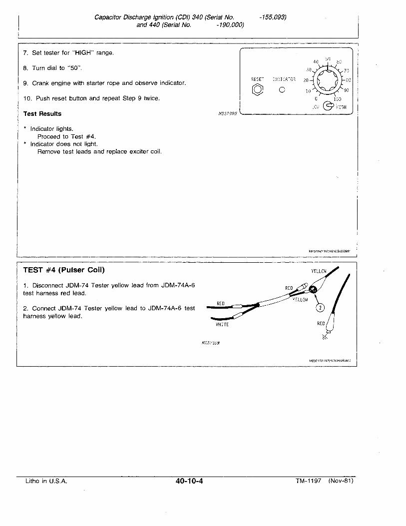
7. Set tester for "HIGH" range.
-155,093)
8. Turn dial to "50".
9. Crank engine with starter rope and observe indicator.
10. Push reset button and repeat Step 9 twice.
Test Results
* Indicator lights.Proceed to Test #4.
* Indicator does not light.Remove test leads and replace exciter coil.
TEST #4 (Pulser Coil)
1. Disconnect JDM-74 Tester yellow lead from JDM-74A-6test harness red lead.
2. Connect JDM-74 Tester yellow lead to JDM-74A-6 testharness yellow lead.
RESET rrWICATOR 20 gO
© 0o 100
LmJ @'HIGH
M23?09N ---------------'
M23709/1197/4010G/250981
RED
WHITE
M23?10N
M23710/1197/4010H/250981
Litho in U.S.A. 40-10-4 TM-1197 (Nov-81)
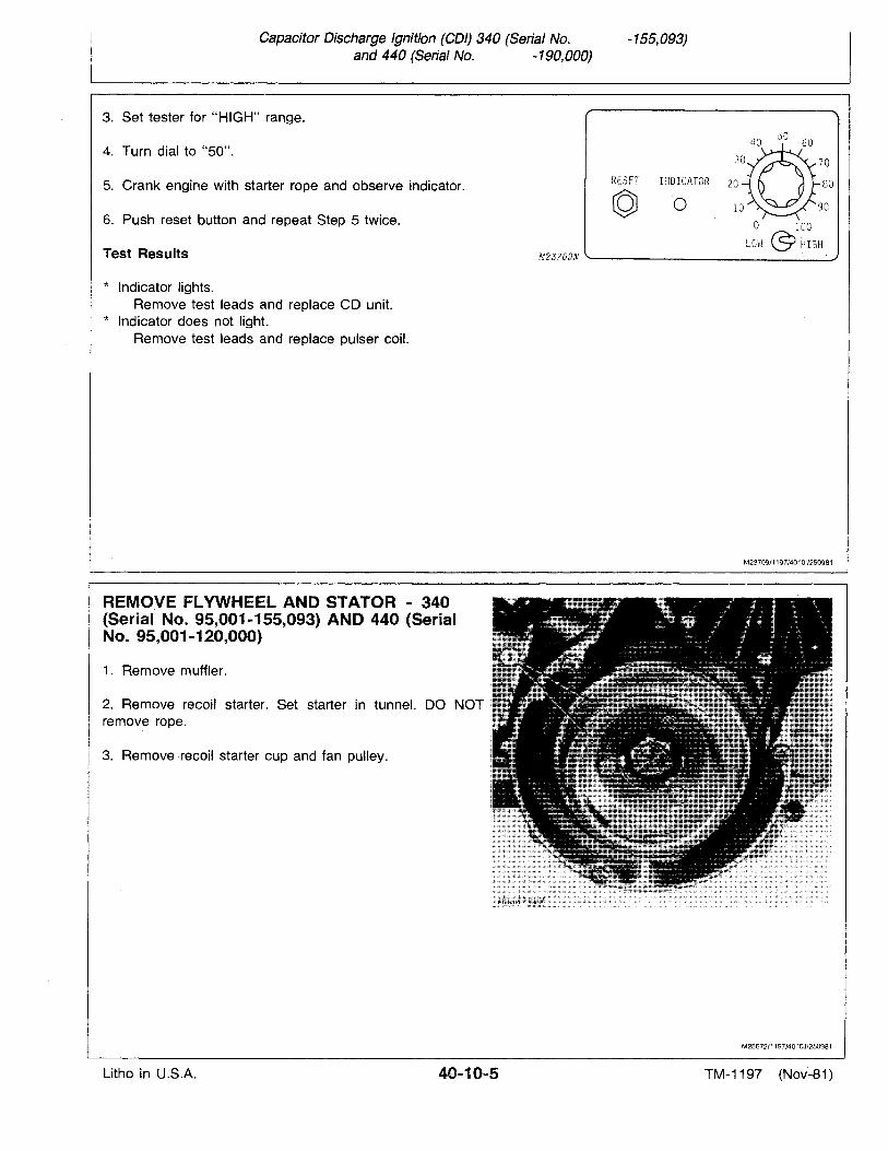
Capacitor Discharge Ignition (COl) 340 (Serial No.and 440 (Serial No. -190,000)
3. Set tester for "HIGH" range.
-155,093)
4. Turn dial to "50".
5. Crank engine with starter rope and observe indicator.
6. Push reset button and repeat Step 5 twice.
Test Results
* Indicator lights.Remove test leads and replace CD unit.
* Indicator does not light.Remove test leads and replace pulser coil.
REMOVE FLYWHEEL AND STATOR - 340(Serial No. 95,001-155,093) AND 440 (SerialNo. 95,001-120,000)
1. Remove muffler.
2. Remove recoil starter. Set starter in tunnel. DO NOTremove rope.
3. Remove recoil starter cup and fan pulley.
RESET I~OICATOR 20 80
© 0
M23?09N '--- ----"
M23709/1197/40101/250981
M25672/1197/401OJ/250981
Litho in U.S.A. 40...10-5 TM-1197 (Nov-81)
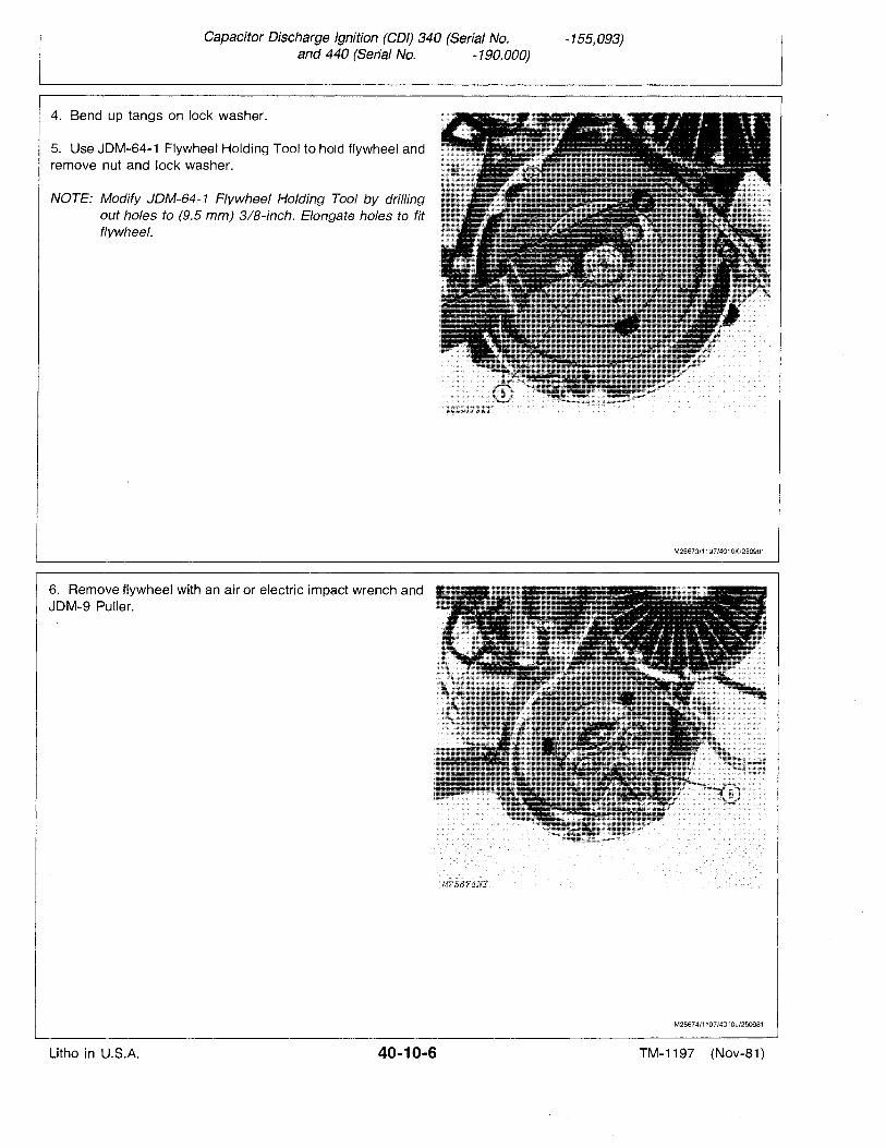
Capacitor Discharge Ignition (COl) 340 (Serial No.and 440 (Serial No. -190,000)
-155,093)
4. Bend up tangs on lock washer.
5. Use JDM-64-1 Flywheel Holding Tool to hold flywheel andremove nut and lock washer.
NOTE: Modify JDM-64-1 Flywheel Holding Tool by drillingout holes to (9.5 mm) 3IB-inch. Elongate holes to fitflywheel.
6. Remove flywheel with an air or electric impact wrench andJDM~9 Puller.
M25673/1197/4010K/250981
M25674/1197/401 OL/250981
Litho in U.S.A. 40-10-6 TM-1197 (Nov-81 )
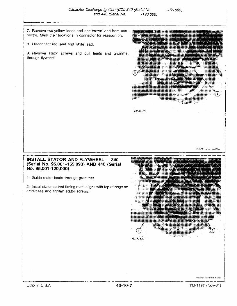
Capacitor Discharge Ignition (COl) 340 (Serial No.and 440 (Serial No. -190,000)
-155,093)
7. Remove two yellow leads and one brown lead from connector. Mark their locations in connector for reassembly.
8. Disconnect red lead and white lead.
9. Remove stator screws and pull leads and grommetthrough flywheel.
INSTALL STATOR AND FLYWHEEL - 340(Serial No. 95,001-155,093) AND 440 (SerialNo. 95,001-120,000)
1. Guide stator leads through grommet.
2. Install stator so that timing mark aligns with top of ridge oncrankcase and tighten stator screws.
M25675/1197/4010M/250981
M25676/1197/401ON/250981
Litho in U.S.A. 40-10-7 TM-1197 (Nov-81)
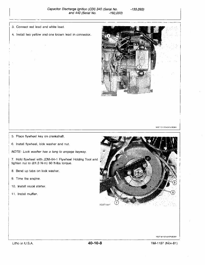
Capacitor Discharge Ignition (COl) 340 (Serial No.and 440 (Serial No. -190,000)
-155,093)
3. Connect red lead and white lead.
4. Install two yellow and one brown lead in connector.
5. Place flywheel key on crankshaft.
6. Install flywheel, lock washer and nut.
NOTE: Lock washer has a tang to engage keyway.
7. Hold flywheel with JDM-64-1 Flywheel Holding Tool andtighten nut to (81.3 N·m) 60 ft-Ibs torque.
8. Bend up tabs on lock washer.
9. Time the engine.
10. Install recoil starter.
11. Install muffler.
M23717/1197/40100/2509B1
M2371B/1197/4010P/2509B1
Litho in U.S.A. 40-10-8 TM-1197 (Nov-81)
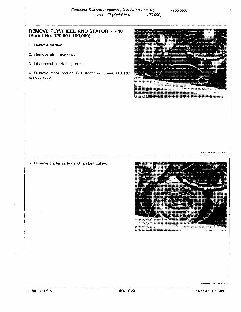
Capacitor Discharge Ignition (COl) 340 (Serial No.and 440 (Serial No. -190,000)
-155,093)
REMOVE FLYWHEEL AND STATOR - 440(Serial No. 120,001-190,000)
1. Remove muffler.
2. Remove air intake duct.
3. Disconnect spark plug leads.
4. Remove recoil starter. Set starter in tunnel. DO NOTremove rope.
5. Remove starter pulley and fan belt pulley.
M25685/1197/401OQ/250981
M25686/1197/4010R/250981
Litho in U.S.A. 40-10-9 TM-1197 (Nov-81)
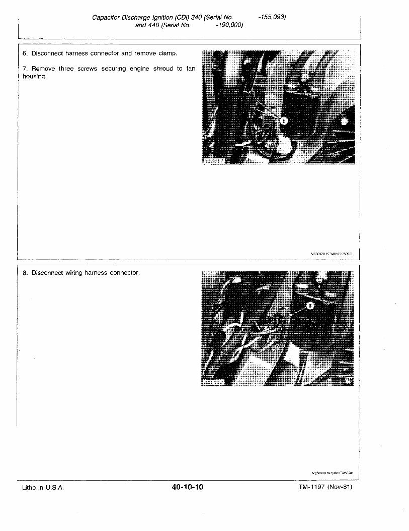
Capacitor Discharge Ignition (COl) 340 (Serial No.and 440 (Serial No. -190,000)
-155,093)
6. Disconnect harness connector and remove clamp.
7. Remove three screws securing engine shroud to fanhousing.
8. Disconnect wiring harness connector.
M25687/1197/401OS/250981
M25688/1197/4010T/2509B1
Litho in U.S.A. 40-10-10 TM-1197 (Nov-81)
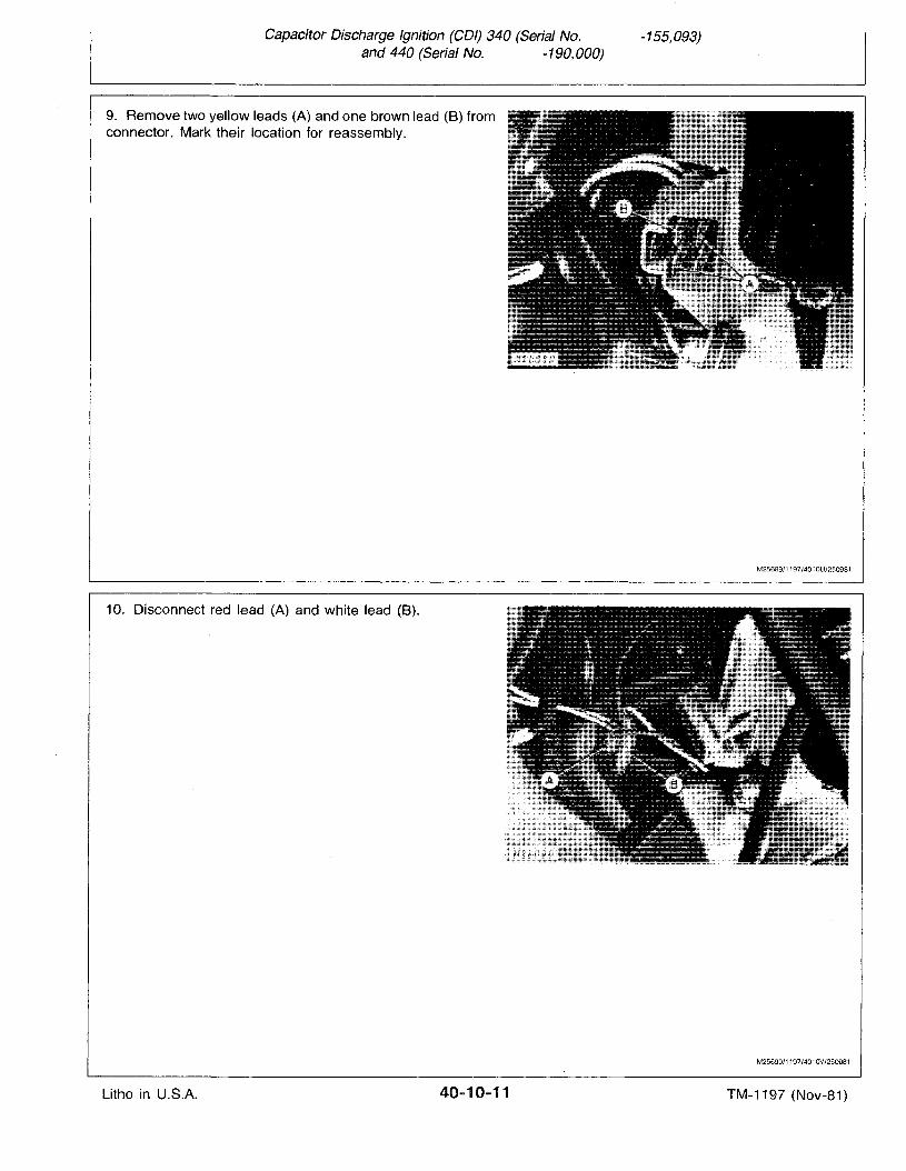
Capacitor Discharge Ignition (COl) 340 (Serial No.and 440 (Serial No. -190,000)
-155,093)
9. Remove two yellow leads (A) and one brown lead (B) fromconnector. Mark their location for reassembly.
10. Disconnect red lead (A) and white lead (B).
M25689/1197/4010U/250981
M25690/1197/401 OV/250981
Litho in U.S.A. 40-10-11 TM-1197 (Nov-81)
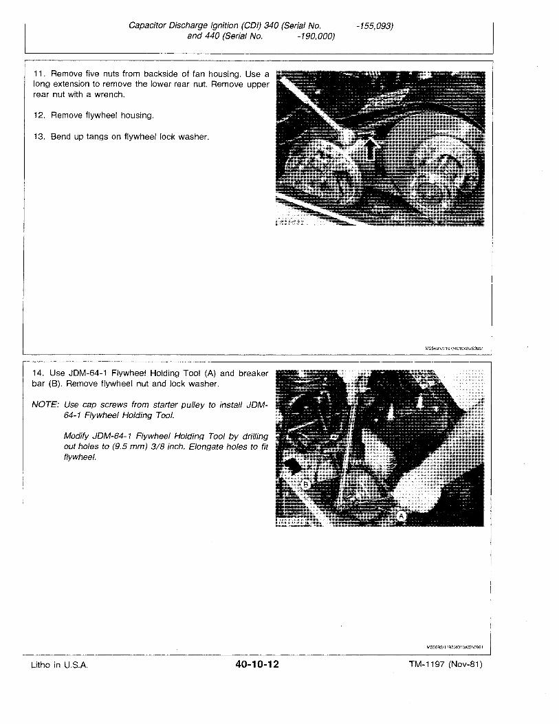
Capacitor Discharge Ignition (COl) 340 (Serial No.and 440 (Serial No. -190,000)
-155,093)
11. Remove five nuts from backside of fan housing. Use along extension to remove the lower rear nut. Remove upperrear nut with a wrench.
12. Remove flywheel housing.
13. Bend up tangs on flywheel lock washer.
14. Use JDM-64-1 Flywheel Holding Tool (A) and breakerbar (8). Remove flywheel nut and lock washer.
NOTE: Use cap screws from starter pulley to install JDM64-1' Flywheel Holding Tool.
Modify JDM-64-1 Flywheel Holding Tool by drillingout holes to (9.5 mm) 3/8 inch. Elongate holes to fitflywheel.
M25691/1197/4010W/2509B1
M25692/1197/401 OX/2509B1
Litho in U.S.A. 40-10-12 TM-1197 (Nov-81)
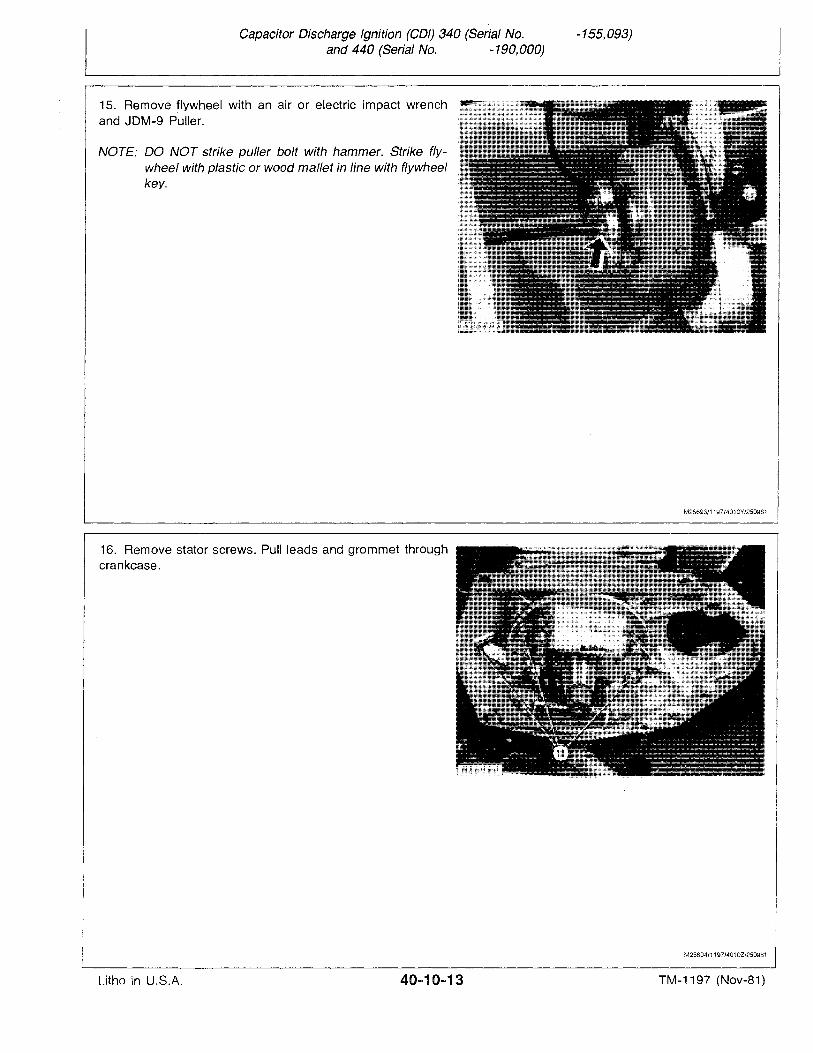
Capacitor Discharge Ignition (COl) 340 (Serial No.and 440 (Serial No. -190,000)
-155,093)
15. Remove flywheel with an air or electric impact wrenchand JDM-9 Puller.
NOTE: DO NOT strike puller bolt with hammer. Strike flywheel with plastic or wood mallet in line with flywheelkey.
16. Remove stator screws. Pull leads and grommet throughcrankcase.
M25693/1197/4010Y/250981
M25694/1197/401 OZ/250981
Litho in U.S.A. 40...10-13 TM-1197 (Nov-81)
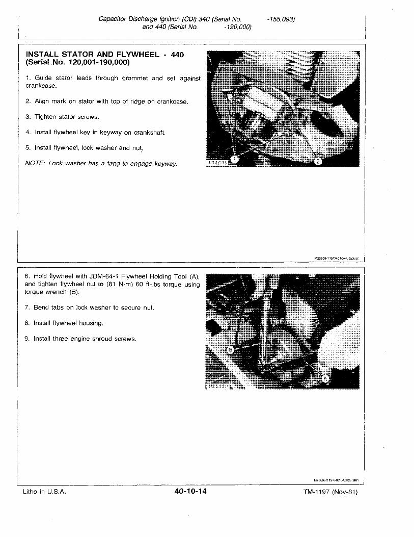
Capacitor Discharge Ignition (COl) 340 (Serial No.and 440 (Serial No. -190,000)
-155,093)
INSTALL STATOR AND FLYWHEEL - 440(Serial ..No. 120,001-190,000)
1. Guide stator leads through grommet and set againstcrankcase.
2. Align mark on statqr with top of ridge on crankcase.
3. Tighten stator screws.
4. Install flywheel key in keyway on crankshaft.
5. Install flywheel, lock washer and nut,
NOTE: Lock washer has a tang to engage keyway.
6. Hold flywheel with JDM-64-1 Flywheel Holding Tool (A),and tighten flywheel nut to (81 Nrn) 60 ft-Ibs torque usingtorque wrench (8).
7. Bend tabs on lock washer to secure nut.
8. Install flywheel housing.
9. Install three engine shroud screws.
M25695/1197/4010AA/250981
M25696/1197/4010AB/250981
Litho in U.S.A. 40-10-14 TM-1197 (Nov-B1)
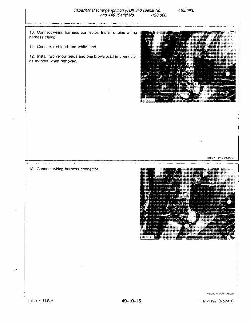
Capacitor Discharge Ignition (COl) 340 (Serial No.and 440 (Serial No. -190,000)
-155,093)
10. Connect wiring harness connector. Install engine wiringharness clamp.
11. Connect red lead and white lead.
12. Install two yellow leads and one brown lead in connectoras marked when removed.
13. Connect wiring harness connector.
M25697/1197/4010AC/250981
M2569B/1197/4010AD/250981
Litho in U.S.A. 40-10-15 TM-1197 (Nov-81)
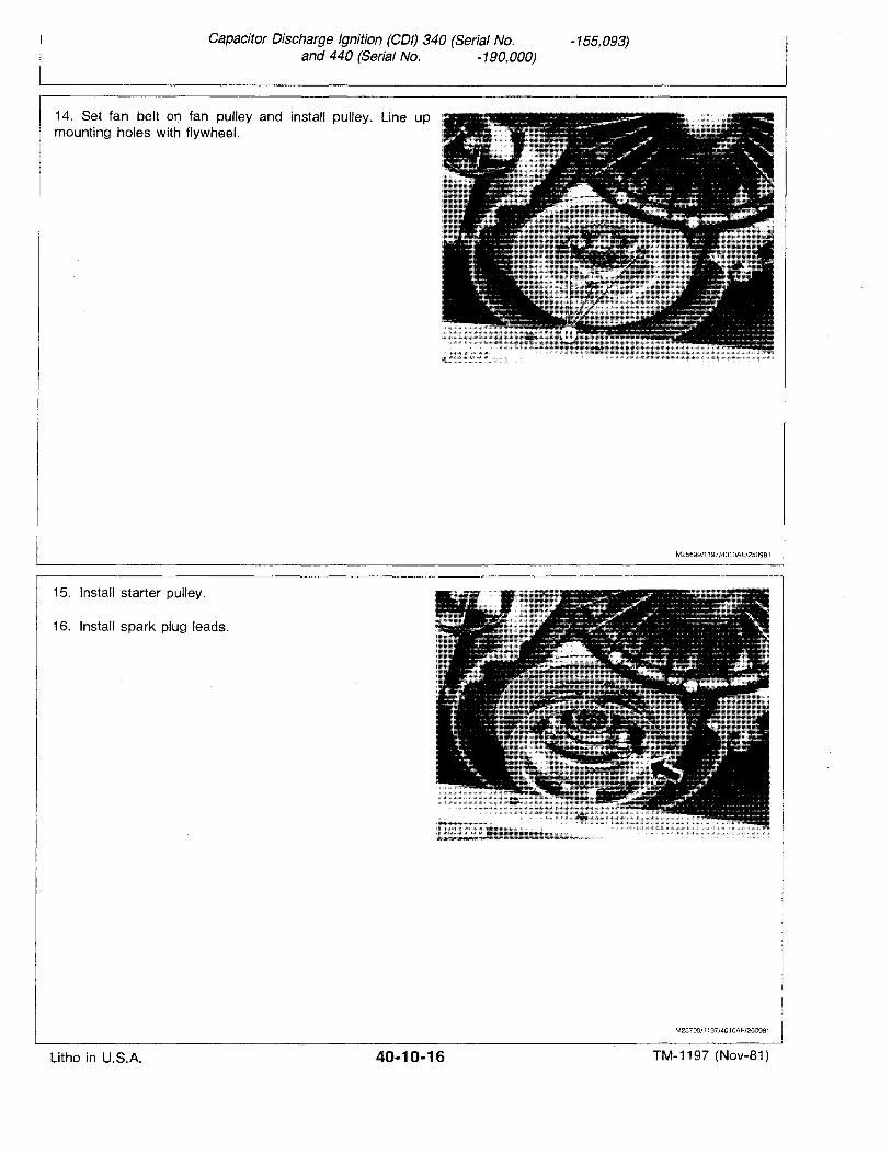
Capacitor Discharge Ignition (COl) 340 (Serial No.and 440 (Serial No. -190,000)
-155,093)
14-. Set fan belt on fan pulley and install pulley. Line upmounting holes with flywheel.
15. Install starter pulley.
16. Install spark plug leads.
M25699/1197/401 OAE/2509B1
M25700/1197/4010AF/2509B1
Litho in U.S.A. 40-10-16 TM-1197 (Nov-81)
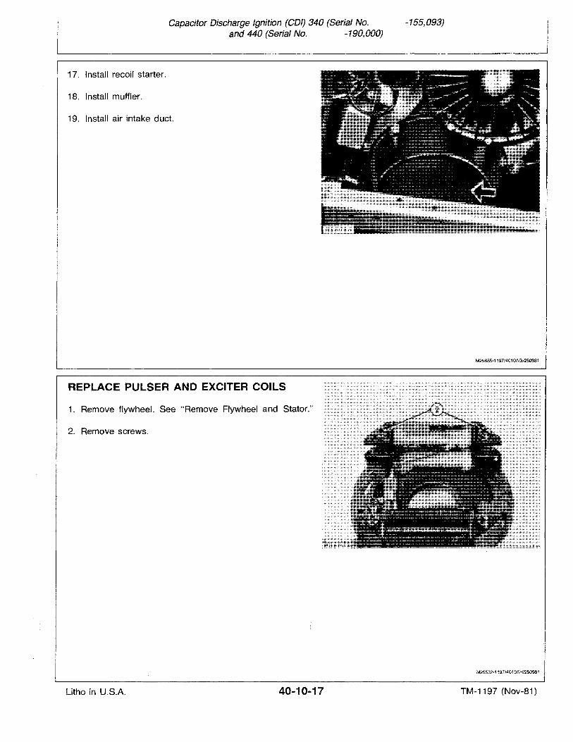
Capacitor Discharge Ignition (COl) 340 (Serial No.and 440 (Serial No. -190,000)
-155,093)
17. Install recoil starter.
18. Install muffler.
19. Install air intake duct.
REPLACE PULSER AND EXCITER COILS
1. Remove flywheel. See "Remove Flywheel and Stator."
2. Remove screws.
M25685/1197/4010AG/250981
M25532/1197/4010AH/250981
Litho in U.S.A. 40-10-17 TM-1197 (Nov-81)
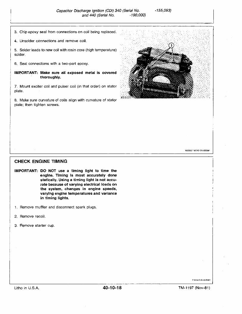
Capacitor Discharge Ignition (COl) 340 (Serial No.and 440 (Serial No. -190,000)
-155,093)
3. Chip epoxy seal from connections on coil being replaced.
4. Unsolder connections and remove coil.
5. Solder leads to new coil with rosin core (high temperature)solder.
6. Seal connections with a two-part epoxy.
IMPORTANT: Make sure all exposed metal is coveredthoroughly.
7. Mount exciter coil and pulser coil (in that order) on statorplate.
8. Make sure curvature of coils align with curvature of statorplate; then tighten screws.
CHECK ENGINE TIMING
IMPORTANT: DO NOT use a timing light to time theengine. Timing is most accurately donestatically. Using a timing light is not accurate because of varying electrical loads onthe system, changes in engine speeds,varying engine temperatures and variancein timing lights.
1. Remove muffler and disconnect spark plugs.
2. Remove recoil.
3. Remove starter cup,
M25533/1197/4010AI/250981
1197/4010AJ/300981
Litho in U.S.A. 40-10-18 TM-1197 (Nov";81)
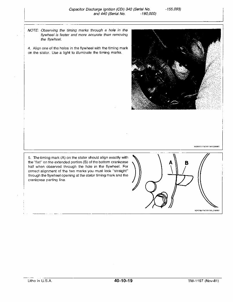
Capacitor Discharge Ignition (COl) 340 (Serial No.and 440 (Serial No. -190,000)
-155,093)
NOTE: Observing the timing marks through a hole in theflywheel is faster and more accurate than removingthe flywheel.
4. Align one of the holes in the flywheel with the timing markon the stator. Use a light to illuminate the timing marks.
M29327/1197/4010AK/300981
5. The timing mark (A) on the stator should align exactly withthe "flat" on the extended portion (B) of the bottom crankcasehalf when observed through the hole in the flywheel. Forcorrect alignment of the two marks you must look "straight"through the flywheel opening at the stator timing mark and thecrankcase parting line.
M29328/1197/4010Al/300981
Litho in U.S.A. 40-10-19 TM-1 1'97 (Nov-81)
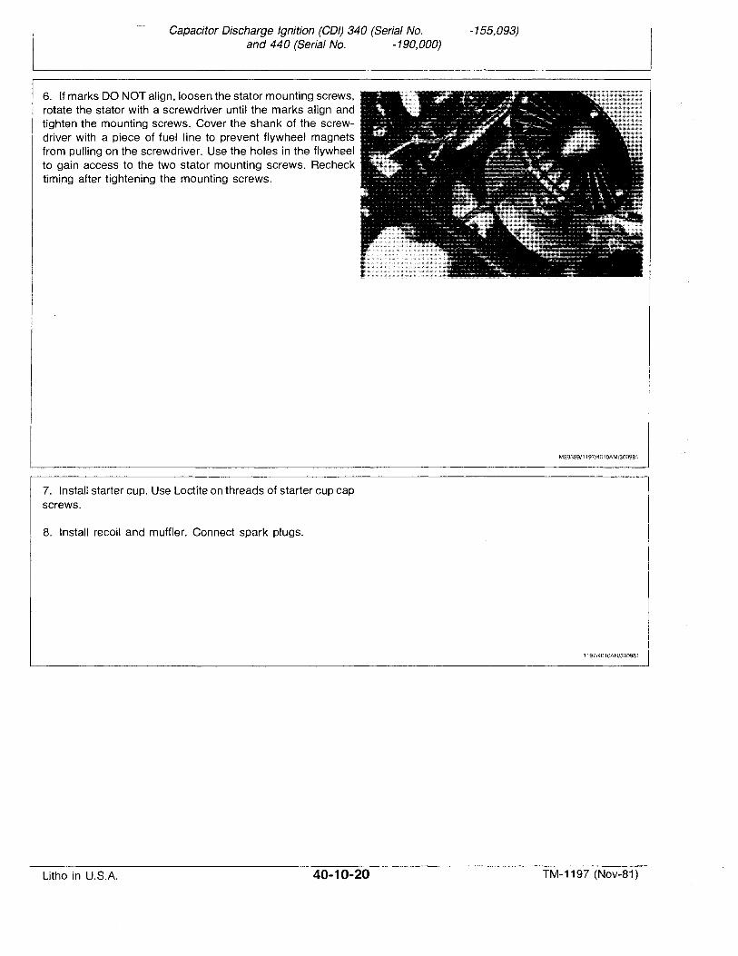
Capacitor Discharge Ignition (COl) 340 (Serial No.and 440 (Serial No. -190,000)
-155,093)
6. If marks DO NOT align, loosen the stator mounting screws,rotate the stator with a screwdriver until the marks align andtighten the mounting screws. Cover the shank of the screwdriver with a piece of fuel line to prevent flywheel magnetsfrom pulling on the screwdriver. Use the holes in the flywheelto gain access to the two stator mounting screws. Rechecktiming after tightening the mounting screws.
7. Install starter cup. Use Loctite on threads of starter cup capscrews.
8. Install recoil and muffler. Connect spark plugs.
M29329/1197/4010AM/3009B1
1197/401 DAN/3009B 1
Litho in U.S.A. 40-10-20 TM-1197 (Nov-81)
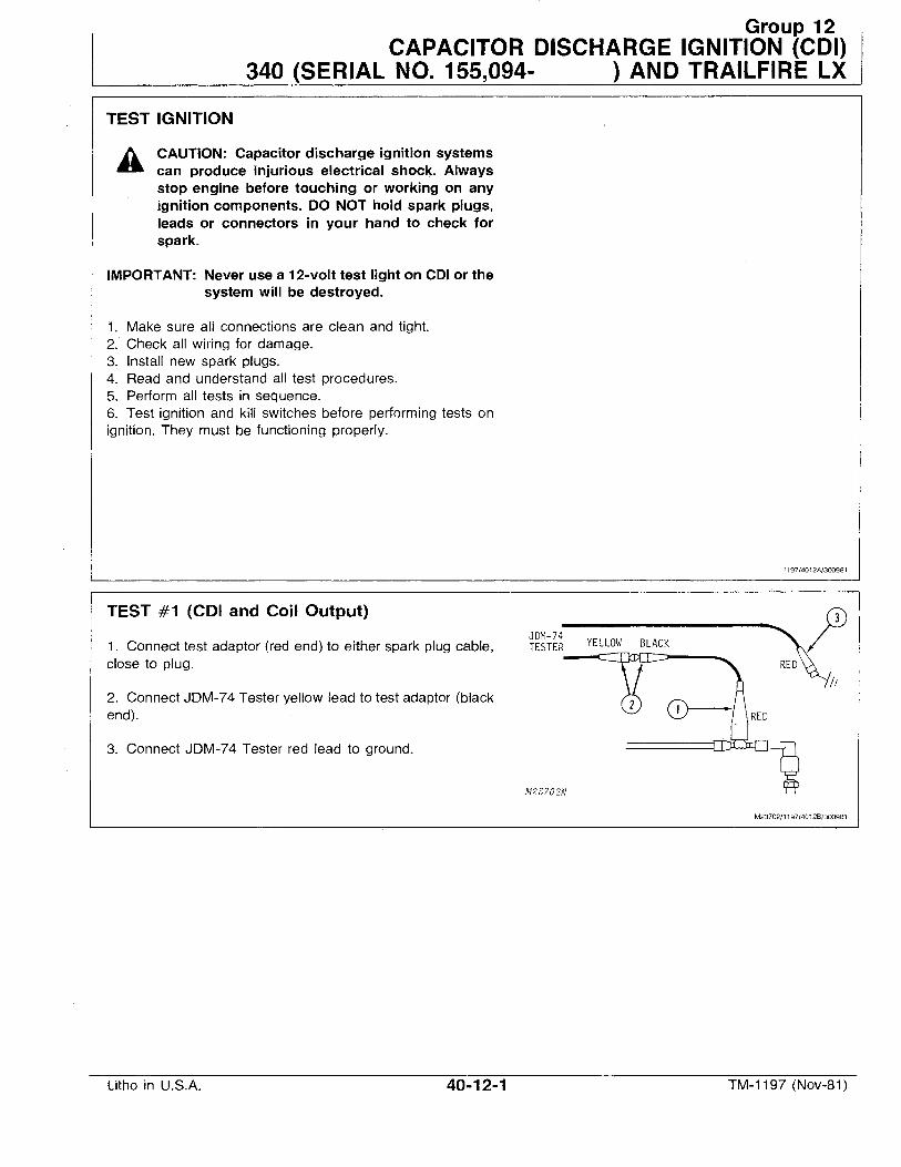
Group 12CAPACITOR DISCHARGE IGNITION (COl)
340 (SERIAL NO. 155,094- ) AND TRAILFIRE LX
TEST IGNITION
A CAUTION: Capacitor discharge ignition systemscan produce injurious electrical shock. Alwaysstop engine before touching or working on anyignition components. DO NOT hold spark plugs,leads or connectors in your hand to check forspark.
IMPORTANT: Never use a 12-volt test light on COlor thesystem will be destroyed.
1. Make sure all connections are clean and tight.2. Check all wiring for damage.3. Install new spark plugs.4. Read and understand all test procedures.5. Perform all tests in sequence.6. Test ignition and kill switches before performing tests onignition. They must be functioning properly.
1197/4012A/300981
TEST #1 (COl and Coil Output)
1. Connect test adaptor (red end) to either spark plug cable,close to plug.
2. Connect JDM-74 Tester yellow lead to test adaptor (blackend).
3. Connect JDM-74 Tester red lead to ground.
JDM-74TESTER YELLOW BLACK
----';--"""'"
M23?02N
M23702/1197/4012B/300981
Litho in U.S.A. 40-12-1 TM-1197 (Nov-81)
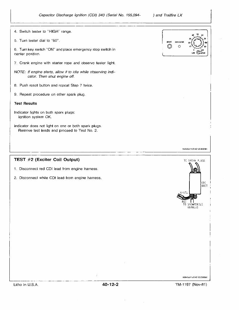
Capacitor Discharge Ignition (COl) 340 (Serial No. 155,094-
4. Switch tester to "HIGH" range.
5. Turn tester dial to "60".
6. Turn key switch "ON" and place emergency stop switch incenter position.
7. Crank engine with starter rope and observe tester light.
NOTE: If engine starts, allow it to idle while observing indicator. Then shut engine off.
8. Push reset button and repeat Step 7 twice.
9. Repeat procedure on other spark plug.
Test Results
Indicator lights on both spark plugs:Ignition system OK.
Indicator does not light on one or both spark plugs.Remove test leads and proceed to Test NO.2.
) and Trailfire LX
RES!T '"OICATO~
ro 0
30@"05060
7020- 80
10 90
o '00LOW ©IGH
TEST #2 (Exciter Coil Output)
1. Disconnect red COl lead from engine harness.
2. Disconnect white COl lead from engine harness.
Litho in U.S.A. 40-12-2
M25593/1197/4012C/300981
TO SPARK PLUGS
M28439/1197/40120/3OO981
TM-1197 (Nov-81)
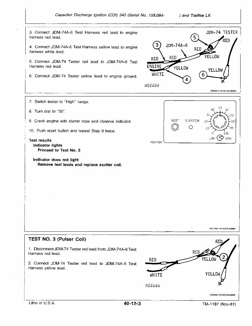
Capacitor Discharge Ignition (COl) 340 (Serial No. 155,094-
3. Connect JDM-74A-6 Test Harness red lead to engineharness red lead.
4. Connect JDM-74A-6 Test Harness yellow lead to engineharness white lead.
5. Connect JDM-74 Tester red lead to JDM-74A-6 TestHarness red lead.
6. Connect JDM-74 Tester yellow lead to engine ground.
7. Switch tester to "High" range.
) and Trailfire LX
(5) JDM-74 TESTER
~ REDJDM-74A-6
RED
M25594/1197/4012E/300981
8. Turn dial to "50".
9. Crank engine with starter rope and observe indicator.
10. Push reset button and repeat Step 9 twice,
Test resultsIndicator lights
Proceed to Test No.3
Indicator does not lightRemove test leads and replace exciter coil.
TEST NO. 3 (Pulser Coil)
1. Disconnect JDM-74 Tester red lead from JDM-74A-6 TestHarness red lead.
2. Connect JDM-74 Tester red lead to JDM-74A-6 TestHarness yellow lead.
RESET I1WICATOR 20 no
© 0o 100
LOH @:> "HIGHM23709N -- ----'
M23709/1197/4012F/300981
RED
M25595
M2559511197/4012G/300981
Litho in U.S.A. TM-1197 (Nov-81)
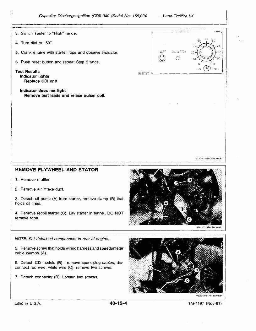
Capacitor Discharge Ignition (COl) 340 (Serial No. 155,094-
3. Switch Tester to "High" range.
) and Trailfire LX
o 100
Lm·l @ ~1IGH
4. Turn dial to "50".
5. Crank engine with starter rope and observe indicator.
6. Push reset button and repeat Step 5 twice.
Test ResultsIndicator lights
Replace COl unit
Indicator does not lightRemove test leads and relace pulser coil.
REMOVE FLYWHEEL AND STATOR
1. Remove muffler.
2. Remove air intake duct.
3. Detach oil pump (A) from starter, remove clamp (B) thatholds oil lines.
4. Remove recoil starter (C). Lay starter in tunnel. DO NOTremove rope.
NOTE: Set detached components to rear of engine.
5. Remove screw that holds wiring harness and speedometercable clamps (A).
6. Detach CD module (B) - remove spark plug cables, disconnect red wire, white wire (C), remove two screws.
7. Detach connector (0). Loosen two screws.
RESET rrwrCATOR 20 no
© 0
M23?09N '---------------
M23709/1197/4012H/300981
M29321/1197/4012J/300981
Litho in U.S.A. 40-12-4 TM-1197 (Nov-81)
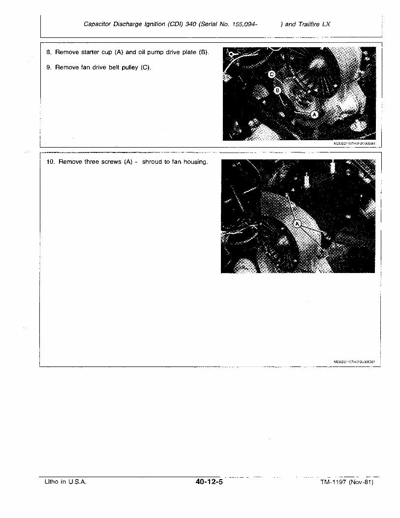
Capacitor Discharge Ignition (COl) 340 (Serial No. 155,094- ) and Trailfire LX
8. Remove starter cup (A) and oil pump drive plate (B).
9. Remove fan drive belt pulley (C).
10. Remove three screws (A) - shroud to fan housing.
M29322/1197/4012K/300981
M29323/1197/4012L/300981
Litho in U.S.A. 40-12-5 TM-1197 (Nov-81)

Capacitor Discharge Ignition (COl) 340 (Serial No. 155,094- ) and Trailfire LX
11. Remove five nuts from backside of fan housing. Use along extension to remove the lower rear nut. Remove upperrear nut with a wrench.
12. Remove flywheel housing.
13. Bend up tangs on flywheel lock washer.
14. Use JDM-64-1 Flywheel Holding Tool (A) and breakerbar (B). Remove flywheel nut and lock washer.
NOTE: Use cap screws from starter pulley to install JDM64-1 Flywheel. Holding Tool.
Modify JDM-64-1 Flywheel Holding Tool by drilling out holesto (9.5 mm) 3/8 inch. Elongate holes to fit flywheel.
M25691/1197/4012L1/300981
M25692/1197/4012M/300981
Litho in U.S.A. 40-12-6 TM-11 97 (Nov-81)
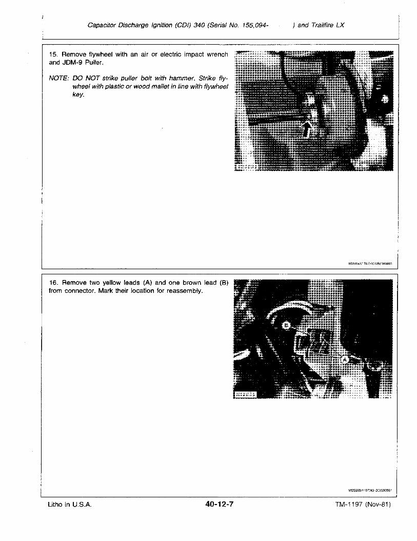
Capacitor Discharge Ignition (COl) 340 (Serial No. 155,094- ) and Trailfire LX
15. Remove flywheel with an air or electric impact wrenchand JDM-9 Puller.
NOTE: DO NOT strike puller bolt with hammer. Strike flywheel with plastic or wood mallet in line with flywheelkey.
16. Remove two yellow leads (A) and one brown lead (8)from connector. Mark their location for reassembly.
M25693/1197/4012N/300981
M25689/1197/40120/300981
Litho in U.S.A. 40-12-7 TM-1197 (Nov-81)
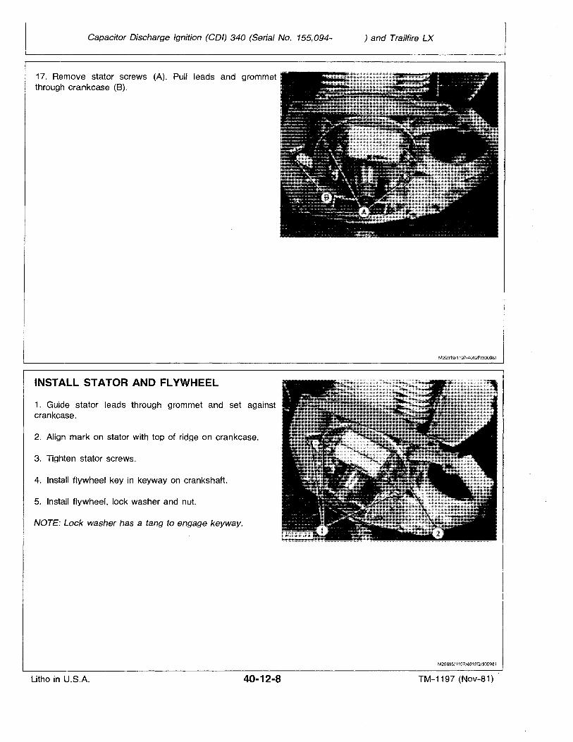
Capacitor Discharge Ignition (COl) 340 (Serial No. 155,094- ) and Trailfire LX
17. Remove stator screws (A). Pull leads and grommetthrough crankcase (8).
INSTALL STATOR AND FLYWHEEL
1. Guide stator leads through grommet and set againstcrankcase.
2. Align mark on stator with top of ridge on crankcase.
3. Tighten stator screws.
4. Install flywheel key in keyway on crankshaft.
5. Install flywheel, lock washer and nut.
NOTE: Lock washer has a tang to engage keyway.
M29319/1197/4012P/300981
M25695/1197/4012Q/300981
Litho in U.S.A. 40-12-8 TM-1197 (Nov-81)
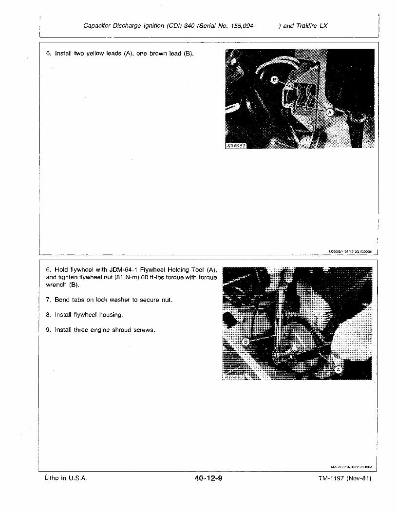
Capacitor Discharge Ignition (COl) 340 (Serial No. 155,094-
6. Install two yellow leads (A), one brown lead (8).
) and Trailfire LX
M25689/1197/4012Q1/300981
6. Hold flywheel with JDM-64-1 Flywheel Holding Tool (A),and tighten flywheel nut (81 N"m) 60 ft-Ibs torque with torquewrench (B).
7. Bend tabs on lock washer to secure nut.
8. Install flywheel housing.
9. Install three engine shroud screws.
M25696/1197/4012R/300981
Litho in U.S.A. 40...12-9 TM-1197 (Nov-81)
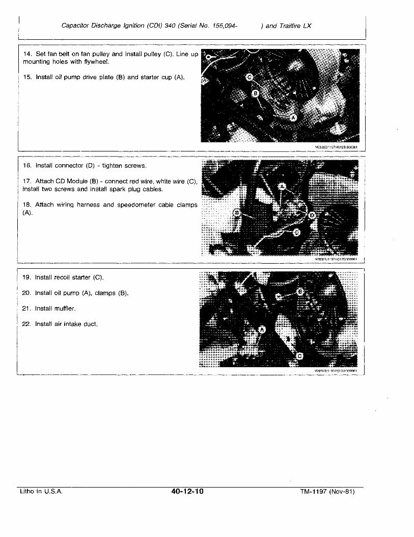
Capacitor Discharge Ignition (COl) 340 (Serial No. 155,094- ) and Trailfire LX
14. Set fan belt on fan pulley and install pulley (C). Line upmounting holes with flywheel.
15. Install oil pump drive plate (B) and starter cup (A).
16. Install connector (D) - tighten screws.
17. Attach CD Module (B) - connect red wire, white wire (C),install two screws and install spark plug cables.
18. Attach wiring harness and speedometer cable clamps(A).
19. Install recoil starter (C).
20. Install oil pump (A), clamps (B).
21. Install muffler.
22. Install air intake duct.
M29322/1197/4012S/300981
M29321/1197/4012T/300981
M29320/1197/4Q12U/300981
Litho in U.S.A. 40-12-10 TM-1197 (Nov-81)
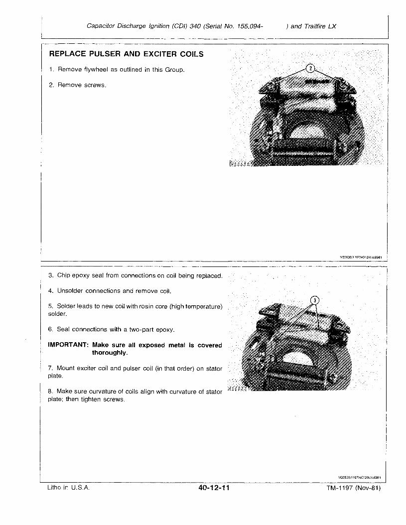
Capacitor Discharge Ignition (COl) 340 (Serial No. 155,094- ) and Trailfire LX
REPLACE PULSER AND EXCITER COILS
1. Remove flywheel as outlined in this Group.
2. Remove screws.
3. Chip epoxy seal from connections on coil being replaced.
4. Unsolder connections and remove coil.
5. Solder leads to new coil with rosin core (high temperature)solder.
6. Seal connections with a two-part epoxy.
IMPORTANT: Make sure all exposed metal is coveredthoroughly.
7. Mount exciter coil and pulser coil (in that order) on statorplate.
8. Make sure curvature of coils align with curvature of statorplate; then tighten screws.
M25532/1197/4012V/300981
M25533/1197/4012W/300981
Litho in U.S.A. TM-1197 (Nov-81)
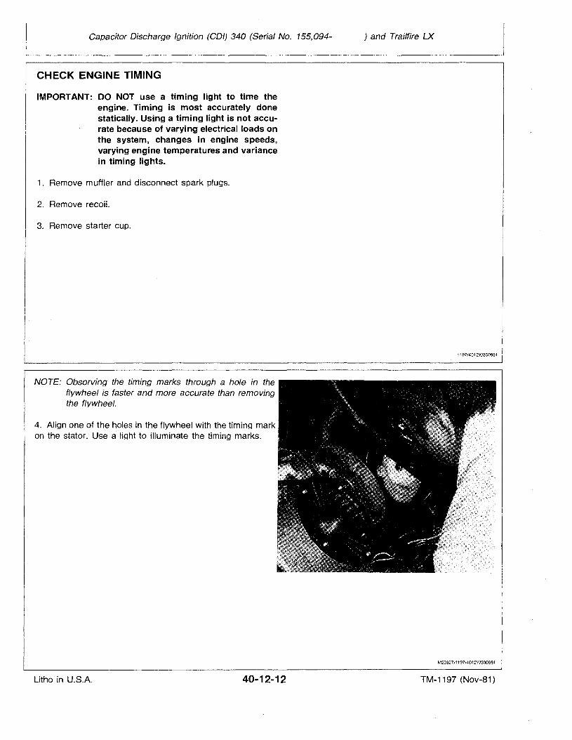
Capacitor Discharge Ignition (COl) 340 (Serial No. 155,094-
CHECK ENGINE TIMING
IMPORTANT: DO NOT use a timing light to time theengine. Timing is most accurately donestatically. Using a timing light is not accurate because of varying electrical loads onthe system, changes in engine speeds,varying engine temperatures and variancein timing lights.
1. Remove muffler and disconnect spark plugs.
2. Remove recoil.
3. Remove starter cup.
) and Trailfire LX
1197/4012X/3009B1
NOTE: Observing the timing marks through a hole in theflywheel is faster and more accurate than removingthe flywheel.
4. Align one of the holes in the flywheel with the timing markon the stator. Use a light to illuminate the timing marks.
M29327/1197J4012Y/300981
Litho in U.S.A. 40-12-12 TM-1197 (Nov-81)
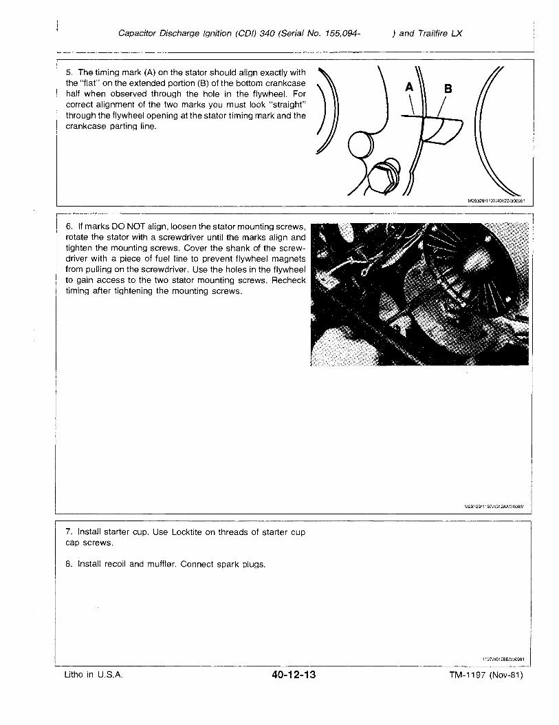
Capacitor Discharge Ignition (COl) 340 (Serial No. 155,094- ) and Trailfire LX
5. The timing mark (A) on the stator should align exactly withthe "flat" on the extended portion (8) of the bottom crankcasehalf when observed through the hole in the flywheel. Forcorrect alignment of the two marks you must look "straight"through the flywheel opening at the stator timing mark and thecrankcase parting line.
M29328/1197/4012Z/300981
6. If marks DO NOT align, loosen the stator mounting screws,rotate the stator with a screwdriver until the marks align andtighten the mounting screws. Cover the shank of the screwdriver with a piece of fuel line to prevent flywheel magnetsfrom pulling on the screwdriver. Use the holes in the flywheelto gain access to the two stator mounting screws. Rechecktiming after tightening the mounting screws.
7. Install starter cup. Use Locktite on threads of starter cupcap screws.
8. Install recoil and muffler. Connect spark plugs.
M29329/1197/4012AA/300981
1197/401288/300981
Litho in U.S.A. 40-12-13 TM-1197 (Nov-81)

Litho in U.S.A.
Capacitor Discharge Ignition (COl) 340 (Serial No. 155,094-
40-12-14
) ena Trailfire LX
TM-1197 (Nov-81)
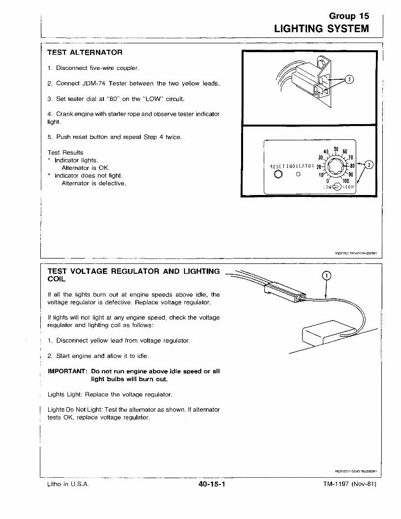
TEST ALTERNATOR
1. Disconnect five-wire coupler.
2. Connect JDM-74 Tester between the two yellow leads.
3. Set tester dial at "80" on the "LOW" circuit.
4. Crank engine with starter rope and observe tester indicatorlight.
5. Push reset button and repeat Step 4 twice.
Test Results* Indicator lights.
Alternator is OK.* Indicator does not light.
Alternator is defective.
TEST VOLTAGE REGULATOR AND LIGHTINGCOIL
If all the lights burn out at engine speeds above idle, thevoltage regulator is defective. Replace voltage regulator.
If lights will not light at any engine speed, check the voltageregulator and lighting coil as follows:
1. Disconnect yellow lead from voltage regulator.
2. Start engine and allow it to idle.
IMPORTANT: Do not run engine above idle speed or alllight bulbs will burn out.
Lights Light: Replace the voltage regulator.
Lights Do Not Light: Test the alternator as shown. If alternatortests OK, replace voltage regulator.
Group 15
LIGHTING SYSTEM
3~0050 6070
RESETIN 0 I CAT 0 R 20 80ro 0 10 90o 100LOW~HIGH
M23726/1197/4015A/250981
M23727/1197/4015B/250981
Litho in U.S.A. 40-15-1 TM-1197 (Nov-81)
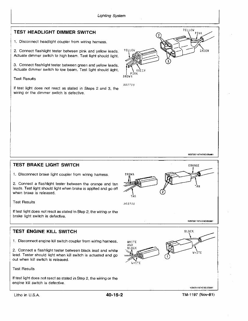
Lighting System
TEST HEADLIGHT DIMMER SWITCH
1. Disconnect headlight coupler from wiring harness.
2. Connect flashlight tester between pink and yellow leads.Actuate dimmer switch to high beam. Test light should light.
3. Connect flashlight tester between green and yellow leads.Actuate dimmer switch to low beam. Test light should light.
Test Results
M23?28
If test light does not react as stated in Steps 2 and 3, thewiring or the dimmer switch is defective.
TEST BRAKE LIGHT SWITCH
M23728/1197/4015C/250981
ORANGE
1. Disconnect brake light coupler from wiring harness.
2. Connect a flashlight tester between the orange and tanleads. Test light should light when brake is applied and go offwhen brake is released.
Test Results
If test light does not react as stated in Step 2, the wiring or thebrake light switch is defective.
TAN
M23?29
M2372911197/4015D/250981
TEST ENGINE KILL SWITCH
1. Disconnect engine kill switch coupler from wiring harness.
2. Connect a flashlight tester between black lead and whitelead. Tester should light when kill switch is actuated and goout when kill switch is released.
Test Results
If test light does not react as stated in Step 2, the wiring or theengine kill switch is defective.
BLACK
M28476/1197/4015E/250981
Litho in U.S.A. 40·15·2 TM-1197 (Nov-81)
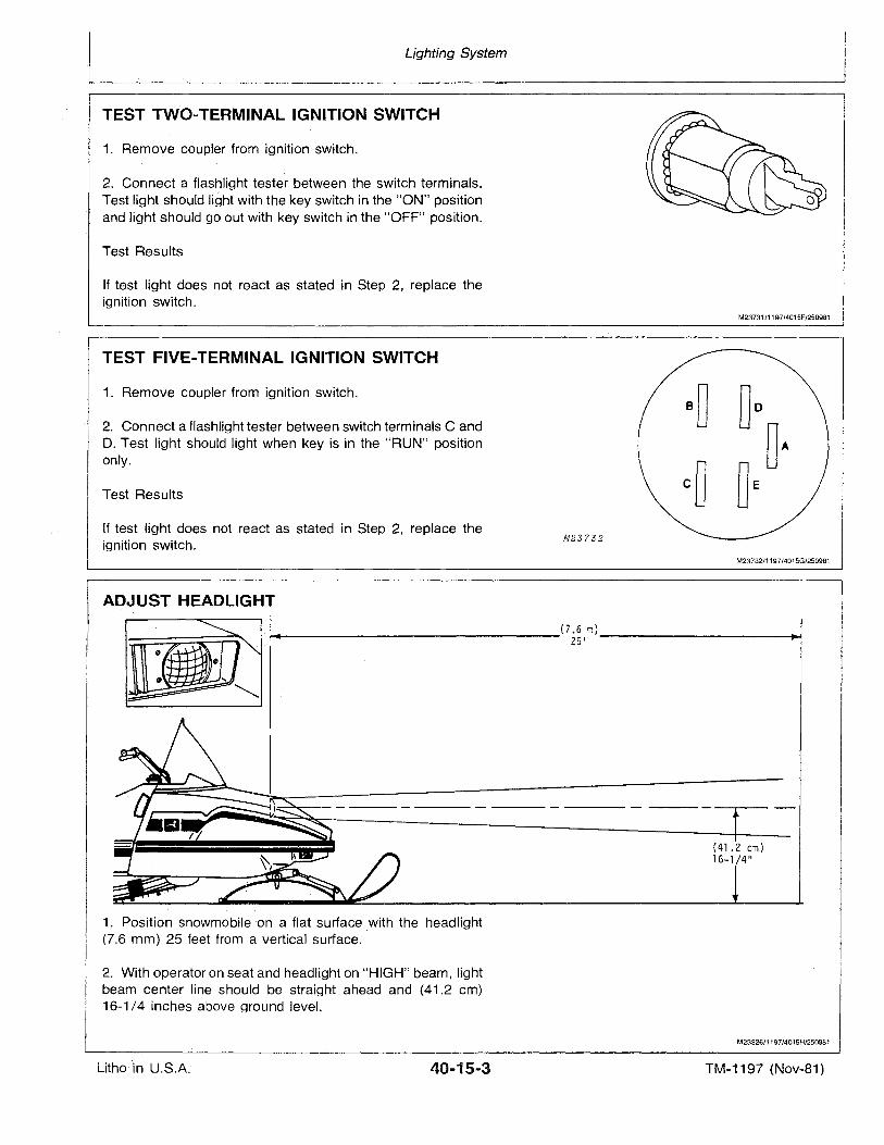
Lighting System
TEST TWO-TERMINAL IGNITION SWITCH
1. Remove coupler from ignition switch.
2. Connect a flashlight tester between the switch terminals.Test light should light with the key switch in the "ON" positionand light should go out with key switch in the "OFF" position.
Test Results
If test light does not react as stated in Step 2, replace theignition switch.
M23731/1197/4015F/250981
TEST FIVE-TERMINAL IGNITION SWITCH
1. Remove coupler from ignition switch.
2. Connect a flashlight tester between switch terminals C andD. Test light should light when key is in the "RUN" positiononly.
Test Results
If test light does not react as stated in Step 2, replace theignition switch.
M23?32
M23732/1197/4015G/250981
'1 ADJUST HEADLIGH.T~ {7.6 m) ~
25'
(41.2 em)16-1/4"
1. Position snowmobile on a flat surface with the headlight(7.6 mm) 25 feet from a vertical surface.
2. With operator on seat and headlight on "HIGH" beam, lightbeam center line should be straight ahead and (41.2 em)16-1/4 inches above ground level.
M23326/1197/4015H/250981
Litho in U.S.A.' 40-15-3 TM-1197 (Nov-81)
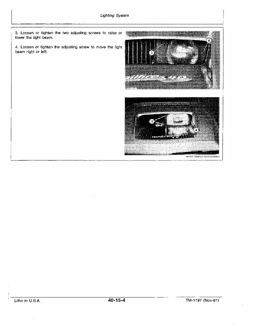
Lighting System
3. Loosen or tighten the two adjusting screws to raise orlower the light beam.
4. Loosen or tighten the adjusting screw to move the light I
beam right or left.
M23327 M29294/1197/40151/250981
Litho in U.S.A. 40-15-4 TM-1197 (Nov-81)
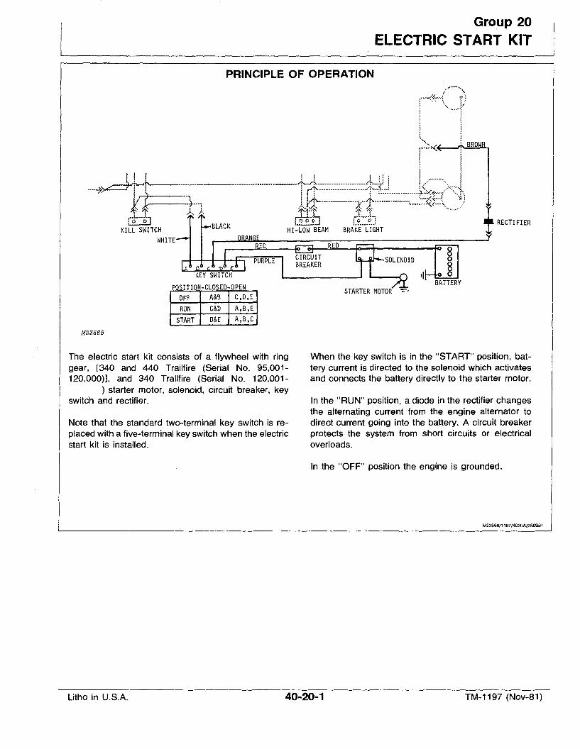
Group 20
ELECTRIC START KIT
PRINCIPLE OF OPERATION
r--<~-(=f; tl
I J.
<, ~:.....;..<:~
!----t ! I \I i I ."-'. I
------- I
I [,.1..._;,,.0 Q « .9....9.._!.
HI-LOW BEAM BRAKE LIGHT
II ~'"-7>~)~---''''·1
tk t"""1..l -J' /', .•-\
[~--:tI
KILL SWITCHWHITE
OFF A&B C,D,ERUN C&D A,B,E
START D&E A,B,C
M23568
'I BATTERYSTARTER MOTOR - .
tRECTIFIER
The electric start kit consists of a flywheel with ringgear, [340 and 440 Trailfire (Serial No. 95,001120,000)], and 340 Trailfire (Serial No. 120,001-
) starter motor, solenoid, circuit breaker, keyswitch and rectifier.
Note that the standard two-terminal key switch is replaced Witha five-terminal key switch when the electricstart kit is installed.
When the key switch is in the "START" position,battery currerit is directed to the solenoid which activatesand connects the battery directly to the starter motor.
In the "RUN" position, a diode in the rectifier changesthe alternating current from the engine alternator todirect current going into the battery. A circuit breakerprotects the system from short circuits or electricaloverloads.
In the "OFF" position the engine is grounded.
M23568/1197/4020AJ250981
Litho in U.S.A. 40-20-1 TM-1197 (Nov-81)
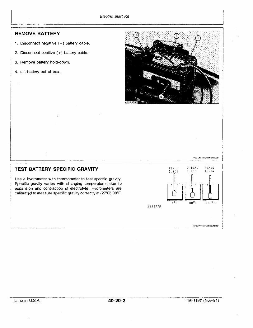
Electric Start Kit
REMOVE BATTERY
1. Disconnect negative (-) battery cable.
2. Disconnect positive (+) battery cable.
3. Remove battery hold-down.
4. Lift battery out of box.
M23733/1197/4020B/250981
TEST BATTERY SPECIFIC GRAVITY READS1.282
ACTUAL READS1.250 1.234
Use a hydrometer with thermometer to test specific gravity.Specific gravity varies with changing temperatures due toexpansion and contraction of electrolyte. Hydrometers arecalibrated to measure specific gravity correctly at (27°C) BO°F.
M16377N
M16377/1197/402OC/250981
Litho in U.S.A. 40-20-2 TM-1197 (Nov-81)
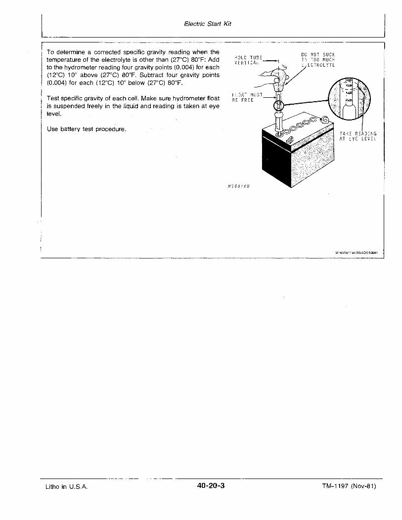
Electric Start Kit
To determine a corrected specific gravity reading when thetemperature of the electrolyte is other than (27°C) 80°F: Addto the hydrometer reading four gravity points (0.004) for each(12°C) 10° above (27°C) 80°F. Subtract four gravity points(0.004) for each (12°C) 10° below (27°C) 80°F.
Test specific gravity of each cell. Make sure hydrometer floatis suspended freely in the liquid and reading is taken at eyelevel.
Use battery test procedure.
HOLD TUBEVERTICAL ~I
FLOAT MUSTBE FREE
M16378N
DO NOT SUCKIN TOO MUCH
ECTROLYTE
M16378/1197/4020D/250981
Litho in U.S.A. 40-20-3 TM-1197 (Nov-81)
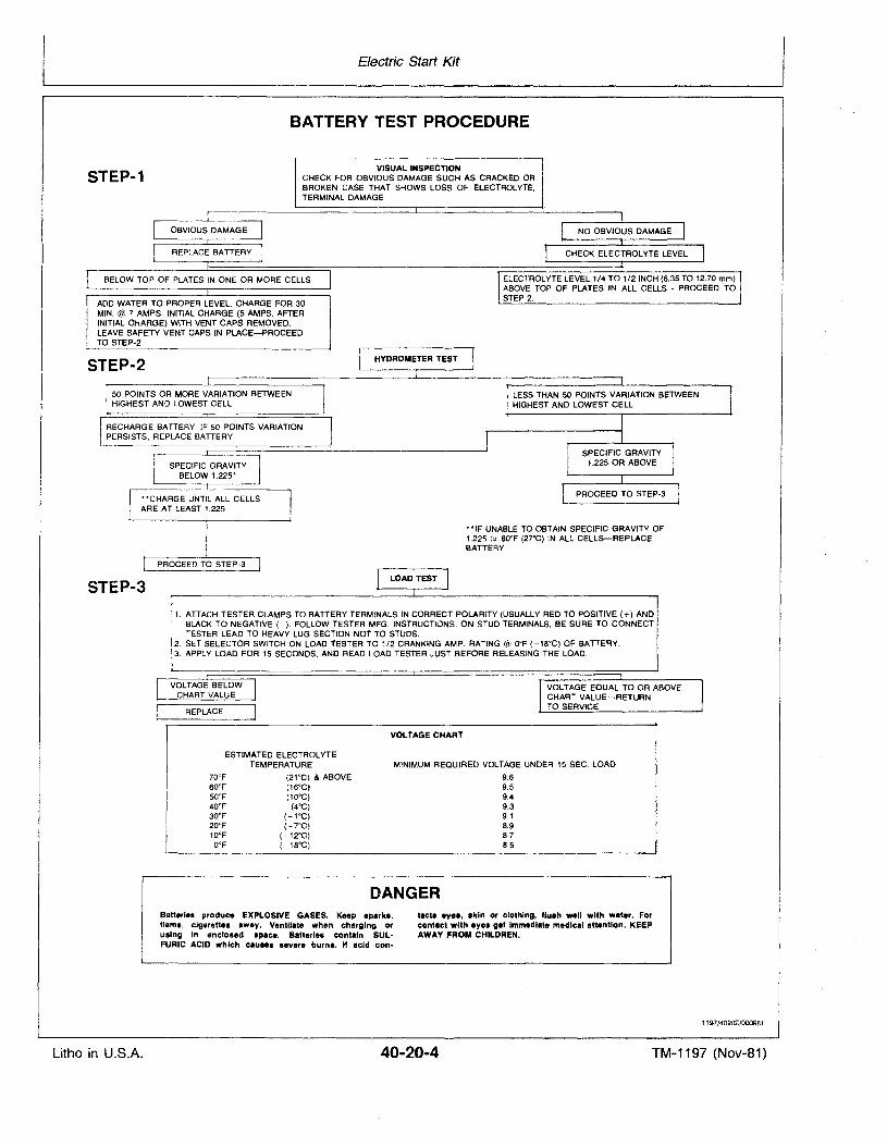
Electric Start Kit
BATTERY TEST PROCEDURE
STEP-1VISUAL INSPECTION
CHECK FOR OBVIOUS DAMAGE SUCH AS CRACKED ORBROKEN CASE THAT SHOWS LOSS OF ELECTROLYTE,TERMINAL DAMAGE
ADD WATER TO PROPER LEVEL. CHARGE FOR 30MIN. @ 7 AMPS. INITIAL CHARGE (5 AMPS. AFTERINITIAL CHARGE) WITH VENT CAPS REMOVED.LEAVE SAFETY VENT CAPS IN PLACE-PROCEEDTO STEP-2
STEP-2
50 POINTS OR MORE VARIATION BETWEENHIGHEST AND LOWEST CELL
STEP-3
ELECTROLYTE LEVEL 1/4 TO 1/2 INCH (6.35 TO 12.70 mm)ABOVE TOP OF PLATES IN ALL CELLS - PROCEED 'TOSTEP 2.
LESS THAN 50 POINTS VARIATION BETWEENHIGHEST AND LOWEST CELL
**IF UNABLE TO OBTAIN SPECIFIC GRAVITY OF1.225 (u 80°F (27°C) IN ALL CELLS-REPLACEBATTERY
1. ATIACH TESTER CLAMPS TO BATTERY TERMINALS IN CORRECT POLARITY (USUALLY RED TO POSITIVE (+) ANDBLACK TO NEGATIVE (-). FOLLOW TESTER MFG. INSTRUCTIONS. ON STUD TERMINALS, BE SURE TO CONNECTTESTER LEAD TO HEAVY LUG SECTION NOT TO STUDS.
2. SET SELECTOR SWITCH ON LOAD TESTER TO 1/2 CRANKING AMP. RATING (SL. OaF (-18°C) OF BATTERY.3. APPLY LOAD FOR 15 SECONDS, AND READ LOAD TESTER JUST BEFORE RELEASING THE LOAD.
VOLTAGE BELOWCHART VALUE
REPLACE
ESTIMATED ELECTROLVTETEMPERATURE
70°F (21°C) & ABOVE60°F (16°C)50°F (10°C)40°F (4°C)30°F (-1°C)20°F (-7°C)10°F (-12°C)
OaF (-18°C)
VOLTAGE EaUAL TO OR ABOVECHART VALUE-RETURNTO SERVICE
VOLTAGE CHART
MINIMUM REaUIRED VOLTAGE UNDER 15 SEC. LOAD
9.69.59.49.39.18.98.78.5
DANGERBatteries produce EXPLOSIVE GASES. Keep sparka,flame, cigarettes away. Yentllate when charging orusing in encloled Ipace. Batterlea contain SULFURIC ACID which causes levere burna. " acid con-
tacta eyea, akin or clothing, f1uah well with water. Forcontact with eye. get Immediate medicil Ittentlon. KEEPAWAY FROM CHILDREN.
1197/4020E/000981
Litho in U.S.A. 40-20-4 TM-1197 (Nov-81)
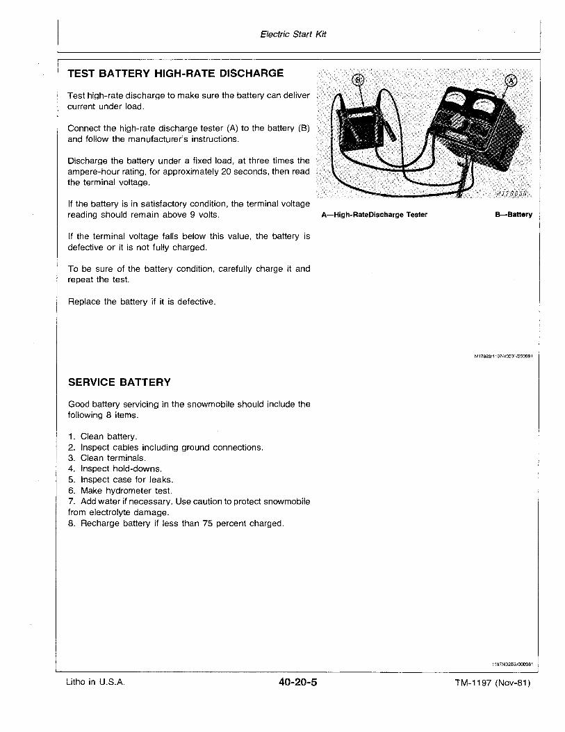
Electric Start Kit
TEST BATTERY HIGH-RATE DISCHARGE
Test high-rate discharge to make sure the battery can delivercurrent under load.
Connect the high-rate discharge tester (A) to the battery (B)and follow the manufacturer's instructions.
Discharge the battery under a fixed load, at three times theampere-hour rating, for approximately 20 seconds, then readthe terminal voltage.
If the battery is in satisfactory condition, the terminal voltagereading should remain above 9 volts. A-High-RateDischarge Tester
If the terminal voltage falls below this value, the battery isdefective or it is not fully charged.
To be sure of the battery condition, carefully charge it andrepeat the test.
Replace the battery if it is defective.
SERVICE BATTERY
Good battery servicing in the snowmobile should include thefollowing 8 items.
1. Clean battery.2. Inspect cables including ground connections.3. Clean terminals.4. Inspect hold-downs.5. Inspect case for leaks.6. Make hydrometer test.7. Add water ifnecessary. Use caution to protect snowmobilefrom electrolyte damage.8. Recharge battery if less than 75 percent charged.
B-Battery
M17883/1197/4020F/250981
1197/402OG/000981
Litho in U.S.A. TM-1197 (Nov-81)
Electric Start Kit
CLEAN BATTERY
Corrosion around the battery terminals is normal. However,an accumulation of corrosion over a long period can shortenthe life of the battery. Keep battery terminals as clean aspossible.
To clean terminals, remove battery from snowmobile. Remove all corrosion using a wire brush. Wash terminals using asolution of one part ordinary baking soda to four parts water.Do not permit cleaning solution to enter battery cells. Flushbattery with clear water.
Wash entire battery case, battery base, and hold-down strapwith clear water. Do not get water on switches and wiringconnections.
Coat terminals with petroleum jelly or a light film of oil toprotect against corrosion.
When installing battery, connect cable to positive terminalfirst. Be sure to slide rubber boot down on cable until terminaland clamp are completely covered.
ACTIVATE NEW BATTERY
Activate a new battery before installing it in snowmobile. Thiswill prevent damage to machine in case electrolyte spills.
Add electrolyte until plates are just covered. Leave cell capsoff while charging. Charge at 7 amps for 30 minutes. Afterinitial charge, do not charge battery at more than 5 amps.
Charging the battery will increase battery temperature andraise the electrolyte level. If electrolyte is still below the ring inthe battery neck, add enough electrolyte to fill to the bottom ofthe ring.
Add water as required. A healthy battery will consume aboutone teaspoon of water' per cell each month.
CAUTION: While charging battery, hydrogen andoxygen gases are emitted which are very explosive. Therefore, keep open flames and sparksaway from battery.
CAUTION: Battery electrolyte is poisonous andcan be injurious to eyes, skin and clothing. Handle it carefully.
1197/4020H/OOO9B1
1197/40201/0009B1
Litho in U.S.A. 40-20-6 TM-1197 (Nov-81)
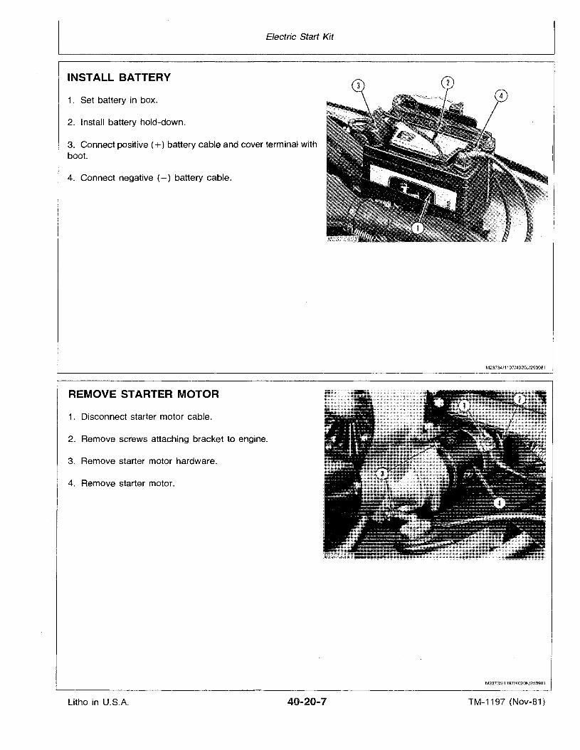
Electric Start Kit
INSTALL BATTERY
1. Set battery in box.
2. Install battery hold-down.
3. Connect positive (+) battery cable and cover terminal withboot.
4. Connect negative (-) battery cable.
REMOVE STARTER MOTOR
1. Disconnect starter motor cable.
2. Remove screws attaching bracket to engine.
3. Remove starter motor hardware.
4. Remove starter motor.
M23734/1197/402OJ/250981
M23735/1197/4020K/250981
Litho in U·.S.A. 40-20-7 TM-1197 (Nov-81)
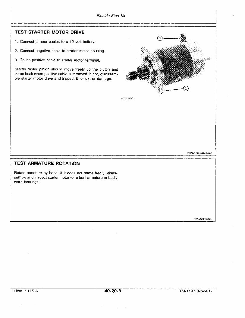
I Electric Start Kit
TEST STARTER MOTOR DRIVE
1. Connect jumper cables to a 12-volt battery.
2. Connect negative cable to starter motor housing.
3. Touch positive cable to starter motor terminal.
Starter motor pinion should move freely up the clutch andcome back when positive cable is removed. If not, disassemble starter motor drive and inspect it for dirt or damage.
TEST ARMATURE ROTATION
Rotate armature by hand. If it does not rotate freely, disassemble and inspect starter motor for a bent armature or badlyworn bearings.
M23736/1197/40201l250981
1197/4020M/000981
Litho in U.S.A. 40-20-8 TM-1197 (Nov-81)
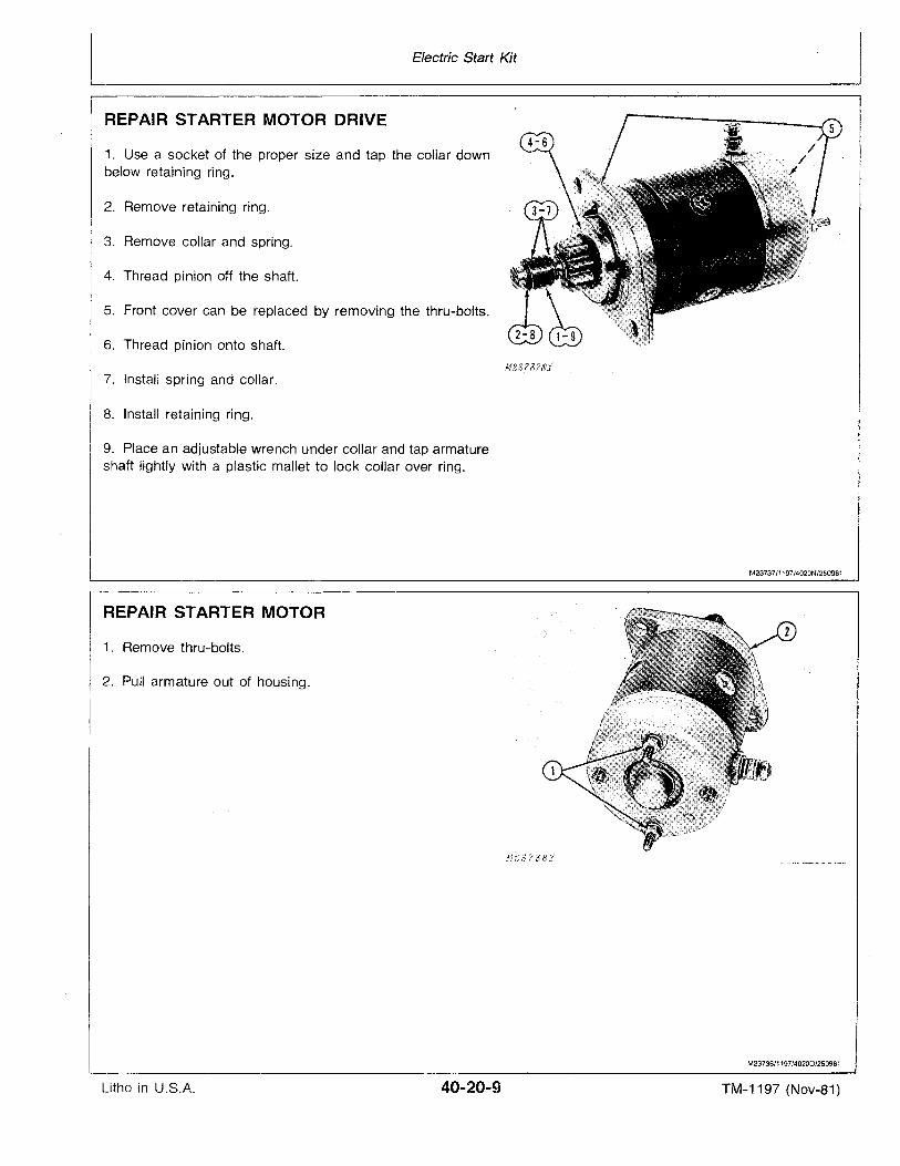
Electric Start KitL ~~~---IREPAIR STARTER MOTOR DRIVE
1. Use a socket of the proper size and tap the collar downbelow retaining ring.
2. Remove retaining ring.
3. Remove collar and spring.
4. Thread pinion off the shaft.
5. Front cover can be replaced by removing the thru-bolts.
6. Thread pinion onto shaft.
M23?8?NJ."7. Install spring and collar.
8. Install retaining ring.
9. Place an adjustable wrench under collar and tap armatureshaft lightly with a plastic mallet to lock collar over ring.
M23737/1197/4020N/250981
REPAIR STARTER MOTOR
1. Remove thru-bolts.
2. Pull armature out of housing.
MBB738.'/
M23738/1197/40200/250981
Litho in U.S.A. 40-20-9 TM-1197 (NoV-81)
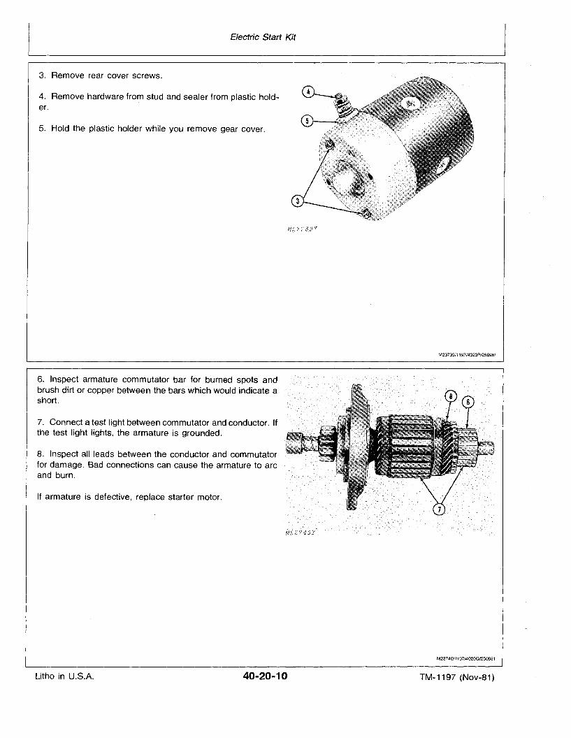
Electric Start Kit
3. Remove rear cover screws.
4. Remove hardware from stud and sealer from plastic holder.
5. Hold the plastic holder while you remove gear cover.
6. Inspect armature commutator bar for burned spots andbrush dirt or copper between the bars which would indicate ashort.
7. Connect a test light between commutator and conductor. Ifthe test light lights, the armature is grounded.
8. Inspect all leads between the conductor and commutatorfor damage. Bad connections can cause the armature to arcand burn.
If armature is defective, replace starter motor.
M23739/1197/4020P/250981
M23740/1197/4020Q/250981
Litho in U.S.A. 40-20-10 TM-1197 (Nov-81)
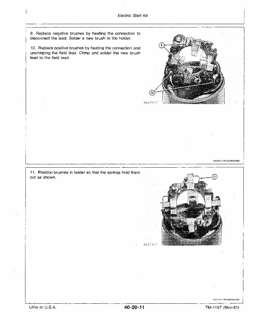
Electric Start Kit
9. Replace negative brushes by heating the connection todisconnect the lead. Solder a new brush to the holder.
10. Replace positive brushes by heating the connection anduncrimping the field lead. Crimp and solder the new brushlead to the field lead.
11. Position brushes in holder so that the springs hold themout as shown.
M23741/1197/4020R/250981
M23742/1197/4020S/250981
Litho in U.S.A. 40..20-11 TM-1197 (Nov-81)
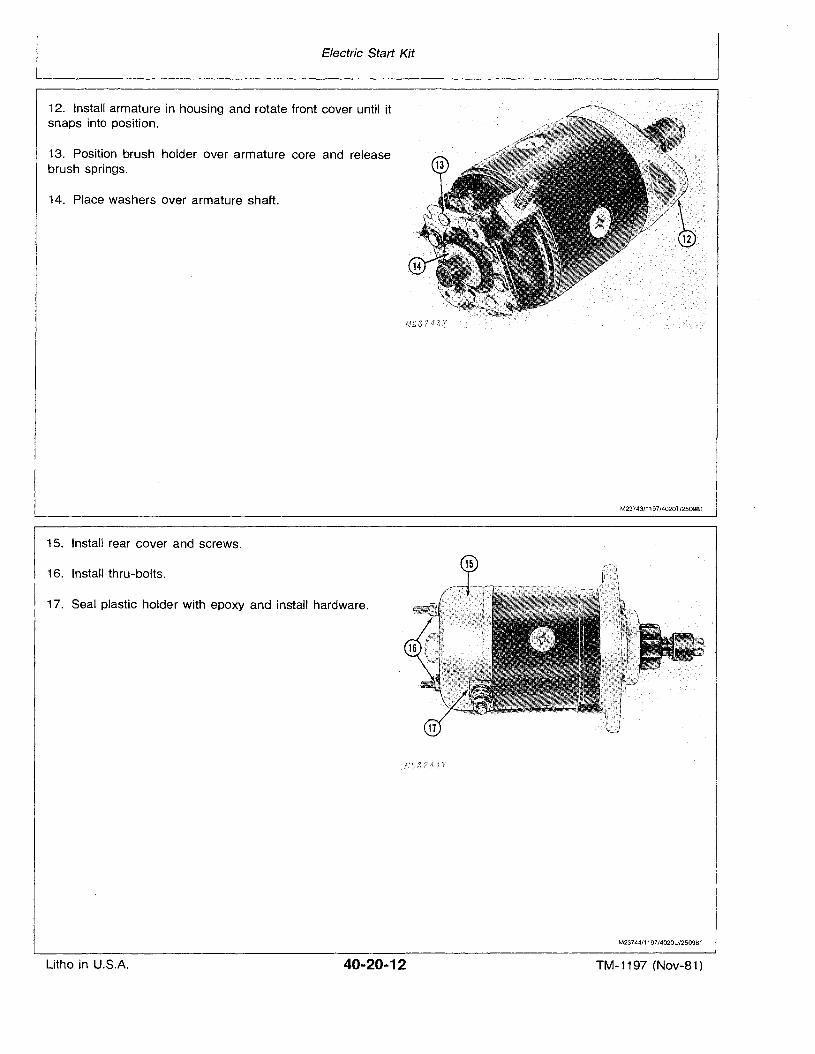
Electric Start Kit
12. Install armature in housing and rotate front cover until itsnaps into position.
13. Position brush holder over armature core and releasebrush springs.
14. Place washers over armature shaft.
15. Install rear· cover and screws.
16. Install thru-bolts.
17. Seal plastic holder with epoxy and install hardware.
M23743/1197/4020T/250981
M23744/1197/4020U/250981
Litho in U.S.A. 40-20-12 TM-1197 (Nov-81)
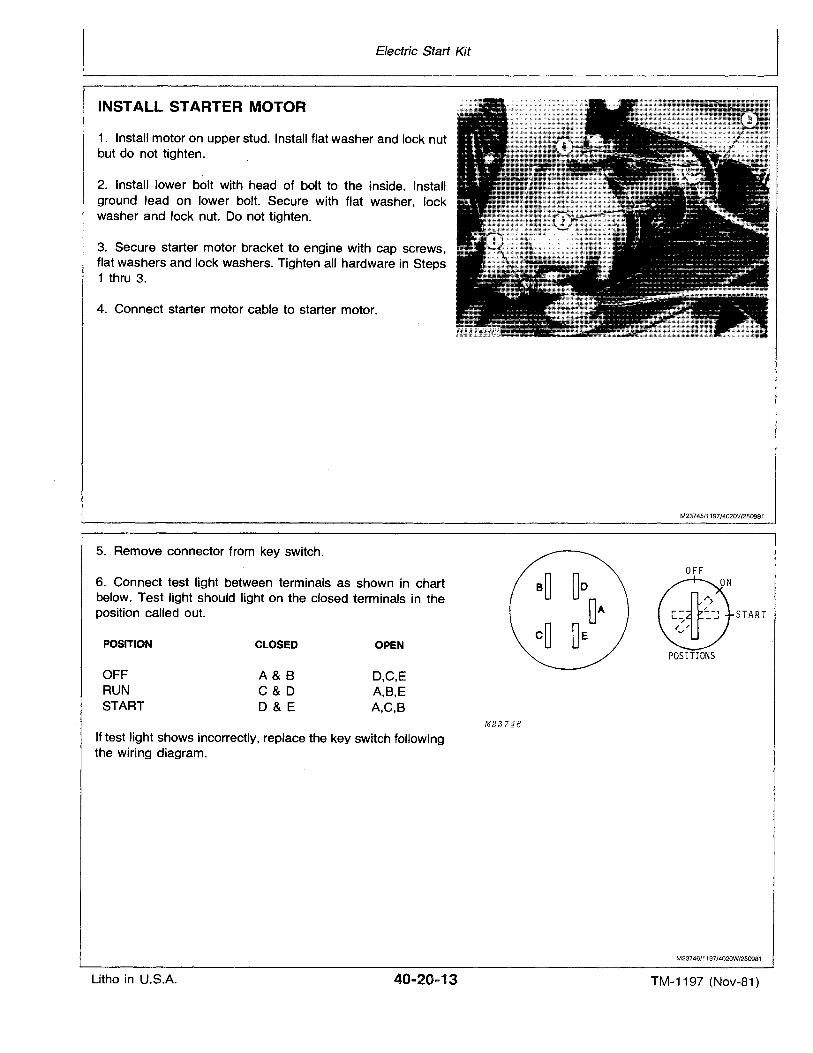
Electric Start Kit
INSTALL STARTER MOTOR
1. Install motor on upper stud. Install flat washer and lock nutbut do not tighten.
2. Install lower bolt with head of bolt to the inside. Installground lead on lower bolt. Secure with flat washer, lockwasher and lock nut. Do not tighten.
3. Secure starter motor bracket to engine with cap screws,flat washers and lock washers. Tighten all hardware in Steps1 thru 3.
4. Connect starter motor cable to starter motor.
M23745/1197/4020V/250981
5. Remove connector from key switch.
START
OFF
OPENCLOSEDPOSITION
6. Connect test light between terminals as shown in chartbelow. Test light should light on the closed terminals in theposition called out.
POSITIONS
OFFRUNSTART
A&BC&DD&E
D,C,EA,B,EA,C,B
M23?46
If test light shows incorrectly, replace the key switch followingthe wiring diagram.
M23746/1197/4020W/250981
Litho in U.S.A. 40-20-13 TM-1197 (Nov-81)
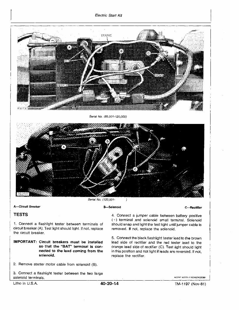
Electric Start Kit
I----------------------------------------------'
Serial No. (95,001-120,000)
Serial No. (120,001-
A-Circuit Breaker B-Solenoid C-Rectifier
TESTS
1. Connect a flashlight tester between terminals ofcircuit breaker (A). Test light should light. If not, replacethe circuit breaker.
IMPORTANT: Circuit breakers must be installedso that the "BAT" terminal is connected to the lead coming from thesolenoid.
2. Remove starter motor cable from solenoid (8).
3. Connect a flashlight tester between the two largesolenoid terminals.
4. Connect a jumper cable between battery positive(+) terminal .and solenoid small terminal. Solenoidshould snap and light the test light until jumper cable isremoved. If not, replace the solenoid.
5. Connect the black flashlight tester lead to the brownlead side of rectifier and the red tester lead to theorange lead side of rectifier (C). Test light should lightin this position and not light if leads are reversed. If not,replace the rectifier.
M23747 M25701/1197/4020Xl250981
Litho in U.S.A. 40-20-14 TM-1197 (Nov-81)
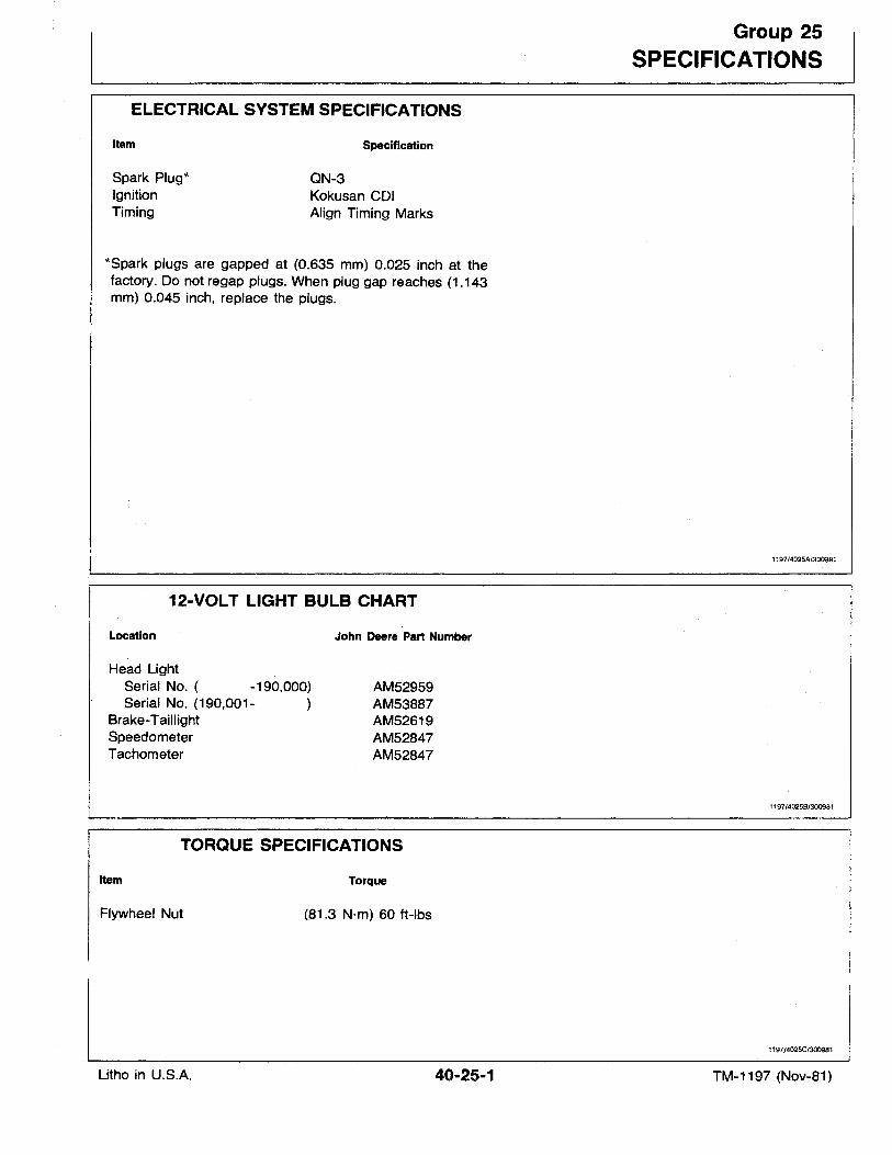
ELECTRICAL SYSTEM S'PECIFICATIONS
Group 25
SPECIFICATIONS
Item
Spark Plug*IgnitionTiming
Specification
QN-3Kokusan COlAlign Timing Marks
*Spark plugs are gapped at (0.635 mm) 0.025 inch at thefactory. Do not regap plugs. When plug gap reaches (1.143mm) 0.045 inch, replace the plugs.
12-VOLT LIGHT BULB CHART
1197/4025N300981
Location
Head LightSerial No. ( -190,000)Serial No. (190,001-
Brake-TaillightSpeedometerTachometer
John Deere Part Number
AM52959AM53887AM52619AM52847AM52847
1197/40258/300981
Item
TORQUE SPECIFICATIONS
Torque
Flywheel Nut
Litho in U.S.A.
(81.3 N'm) 60 ft-Ibs
40-25-1
1197/4025CJ300981
TM-1197 (Nov-81)

Litho in U.S.A.
Specifications
40-25-2 TM-1197 (Nov-81)
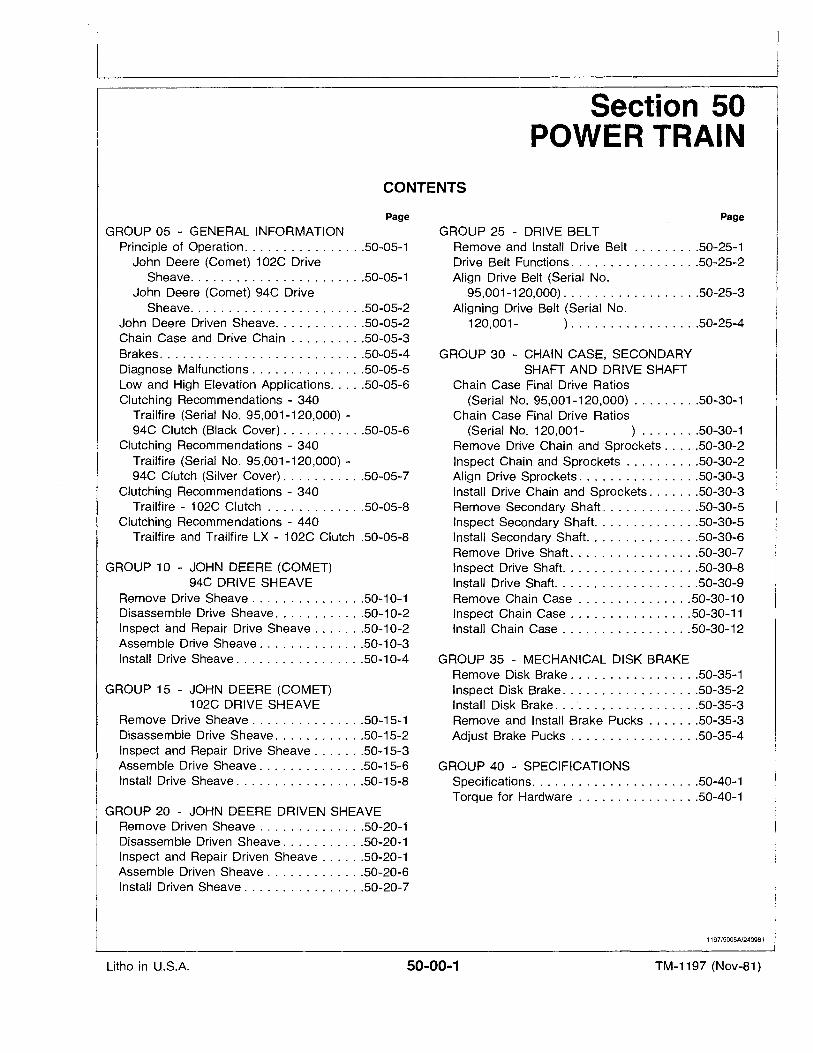
Section 50POWER TRAIN
CONTENTS
Page
GROUP 05 - GENERAL INFORMATIONPrinciple of Operation 50-05-1
John Deere (Comet) 102C DriveSheave 50-05-1
John Deere (Comet) 94C DriveSheave 50-05-2
John Deere Driven Sheave 50-05-2Chain Case and Drive Chain 50-05-3Brakes 50-05-4Diagnose Malfunctions 50-05-5Low and High Elevation Applications 50-05-6Clutching Recommendations - 340
Trailfire (Serial No. 95,001-120,000) -94C Clutch (Black Cover) 50-05-6
Clutching Recommendations - 340Trailfire (Serial No. 95,001-120,000) -94C Clutch (Silver Cover) 50-05-7
Clutching Recommendations - 340Trailfire - 102C Clutch 50-05-8
Clutching Recommendations - 440Trailfire and Trailfire LX - 102C Clutch .50-05-8
GROUP 10 - JOHN DEERE (COMET)94C DRIVE SHEAVE
Remove Drive Sheave 50-10-1Disassemble Drive Sheave 50-10-2Inspect and Repair Drive Sheave 50-10-2Assemble Drive Sheave 50-10-3Install Drive Sheave 50-10-4
GROUP 15 - JOHN DEERE (COMET)102C DRIVE SHEAVE
Remove Drive Sheave 50-15-1Disassemble Drive Sheave 50-15-2Inspect and Repair Drive Sheave 50-15-3Assemble Drive Sheave 50-15-6Install Drive Sheave 50-15-8
GROUP 20 - JOHN DEERE DRIVEN SHEAVERemove Driven Sheave 50-20-1Disassemble Driven Sheave 50-20-1Inspect and Repair Driven Sheave 50-20-1Assemble Driven Sheave 50-20-6Install Driven Sheave 50-20-7
Page
GROUP 25 - DRIVE BELTRemove and Install Drive Belt 50-25-1Drive Belt Functions 50-25-2Align Drive Belt (Serial No.
95,001-120,000) 50-25-3Aligning Drive Belt (Serial No.
120,001- ) 50-25-4
GROUP 30 - CHAIN CASE, SECONDARYSHAFT AND DRIVE SHAFT
Chain Case Final Drive Ratios(Serial No. 95,001-120,000) 50-30-1
Chain Case Final Drive Ratios(Serial No. 120,001- ) 50-30-1
Remove Drive Chain and 'Sprockets 50-30-2Inspect Chain and Sprockets 50-30-2Align Drive Sprockets 50-30-3Install Drive Chain and Sprockets 50-30-3Remove Secondary Shaft 50-30-5Inspect Secondary Shaft. 50-30-5Install Secondary Shaft. 50-30-6Remove Drive Shaft 50-30-7Inspect Drive Shaft. 50-30-8Install Drive Shaft. 50-30-9Remove Chain Case 50-30-10Inspect Chain Case 50-30-11Install Chain Case . . . . . . . . . . . . . . . . .50-30-12
GROUP 35 - MECHANICAL DISK BRAKERemove Disk Brake 50-35-1Inspect Disk Brake 50-35-2Install Disk Brake 50-35-3Remove and Install Brake Pucks 50-35-3Adjust Brake Pucks 50-35-4
GROUP 40 - SPECIFICATIONSSpecifications 50-40-1Torque for Hardware 50-40-1
1197/5005A/240981
Litho in U.S.A. 50-00-1 TM-1197 (Nov-81)

·Litho in U.S.A.
Contents
50-00-2 TM-1197 (Nov-81)
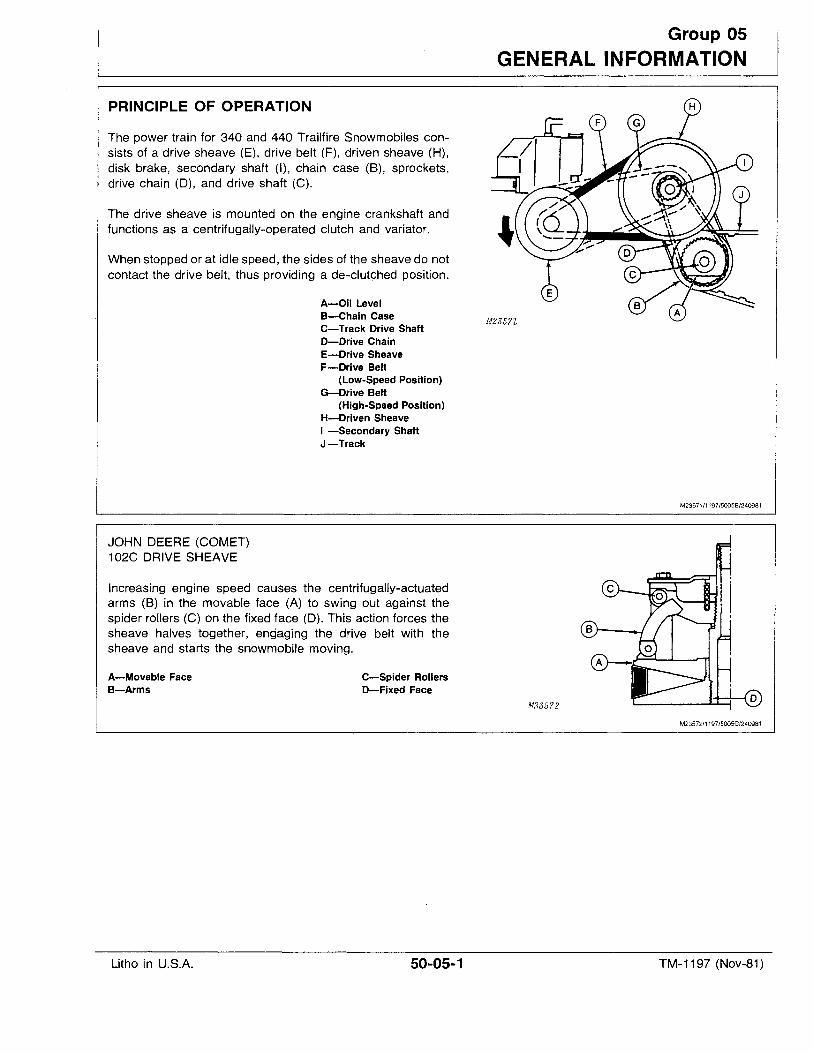
PRINCIPLE OF OPERATION
The power train for 340 and 440 Trailfire Snowmobiles consists of a drive sheave (E), drive belt (F), driven sheave (H),disk brake, secondary shaft (I), chain case (8), sprockets,drive chain (0), and drive shaft (C).
The drive sheave is mounted on the engine crankshaft andfunctions as a centrifugally-operated clutch and variator.
When stopped or at idle speed, the sides of the sheave do notcontact the drive belt, thus providing a de-clutched position.
A-Oil LevelB-Chain CaseC-Track Drive ShaftD-Drive ChainE-Drive SheaveF-Drive Belt
(Low-Speed Position)G-Drive Belt
(High-Speed Position)H-Driven SheaveI -Secondary ShaftJ-Track
Group 05
GENERAL INFORMATION
M2357Z
M23571/1197/50058/240981
JOHN DEERE (COMET)102C DRIVE SHEAVE
Increasing engine speed causes the centrifugally-actuatedarms (B) in the movable face (A) to swing out against thespider rollers (C) on the fixed face (D). This action forces thesheave halves together, engaging the drive belt with thesheave and starts the snowmobile moving.
A-Movable FaceB-Arms
Litho in U.S.A.
C-Spider RollersD-Fixed Face
50-05-1
M235'l2
M23572/1197/5005CJ240981
TM-1197 (Nov-81)
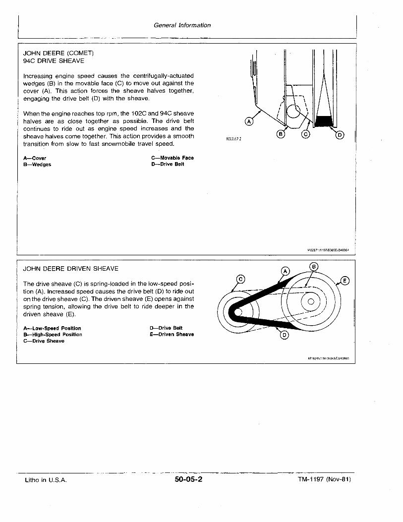
General Information
JOHN DEERE (COMET)94C DRIVE SHEAVE
Increasing engine speed causes the centrifugally-actuatedwedges (8) in the movable face (C) to move out against thecover (A). This action forces the sheave halves together,engaging the drive belt (0) with the sheave.
When the engine reaches top rpm, the 102C and 94C sheavehalves are as close together as possible. The drive beltcontinues to ride out as engine speed increases and thesheave halves come together. This action provides a smoothtransition from slow to fast snowmobile travel speed.
M225'l1
The drive sheave (C) is spring-loaded in the low-speed position (A). Increased speed causes the drive belt (0) to ride outon the drive sheave (C). The driven sheave (E) opens againstspring tension, allowing the drive belt to ride deeper in thedriven sheave (E).
A-CoverB-Wedges
JOHN DEERE DRIVEN SI,EAVE
A-Low-Speed PositionB-High-Speed PositionC-Drive Sheave
Litho in U.S.A.
C-Movable F$ceD-Drive Belt
D-Drive BeltE-Driven Sheave
50-05-2
M22571/1197/5005D/240981
M19245/1197/5005E/240981
TM-1197 (Nov-81)
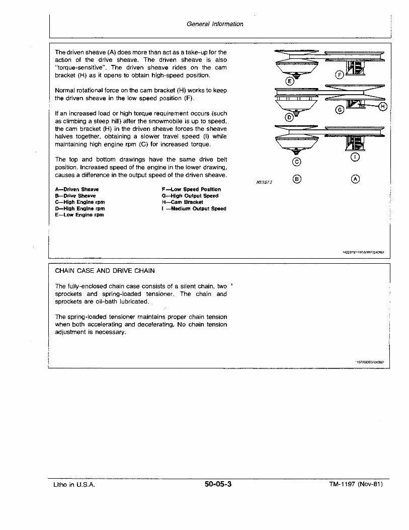
General Information
The driven sheave (A) does more than act as a take-up for theaction of the drive sheave. The driven sheave is also"torque-sensitive". The driven sheave rides on the cambracket (H) as it opens to obtain high-speed position.
Normal rotational force on the cam bracket (H) works to keepthe driven sheave 'in the low speed position (F).
If an increased load or high torque requirement occurs (suchas climbing a steep hill) after the snowmobile is up to speed,the cam bracket (H) in the driven sheave forces the sheavehalves together, obtaining a slower travel speed (I) whilemaintaining high engine rpm (C) for increased torque.
The top and bottom drawings have the same drive beltposition. Increased speed of the engine in the lower drawing,causes a difference in the output speed of the driven sheave.
M2257J
~;
@
®
c
A-Driven SheaveB-Drive SheaveC-High Engine rpmD-High Engine rpmE-Low Engine rpm
CHAIN CASE AND DRIVE CHAIN
F-Low Speed PositionG-High Output SpeedH-Cam BracketI -Medium Output Speed
M225 73/1197/5005F/240981
The fully-enclosed chain case consists of a silent chain, two f
sprockets and spring-loaded tensioner. The chain andsprockets are oil-bath lubricated.
The spring-loaded tensioner maintains proper chain tensionwhen both accelerating and decelerating. No chain tensionadjustment is necessary.
1197/5005G/240981
Litho in U.S.A. 50-05-3 TM-1197 (Nov-81)
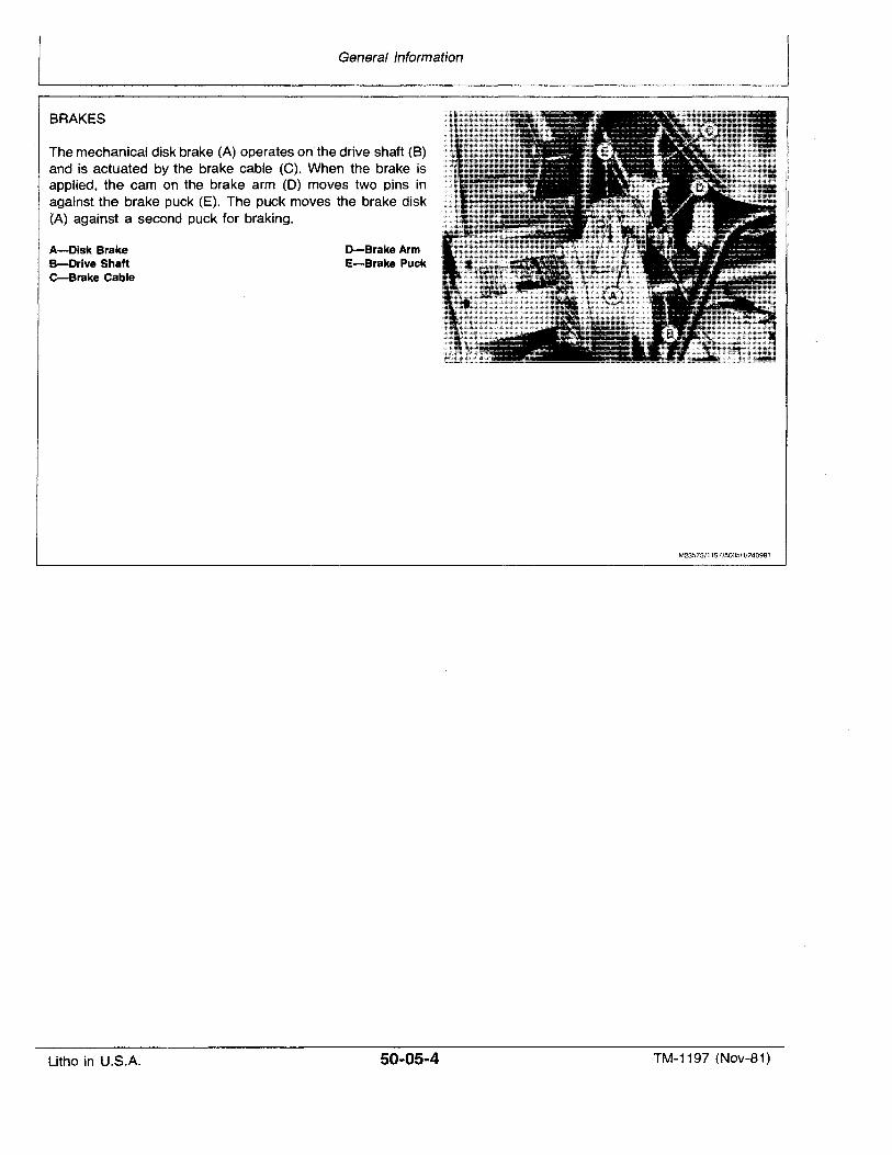
General Information
BRAKES
The mechanical disk brake (A) operates on the drive shaft (B)and is actuated by the brake cable (C). When the brake isapplied, the cam on the brake arm (D) moves two pins inagainst the brake puck (E). The puck moves the brake disk(A) against a second puck for braking.
A-Disk BrakeB-Drive Shafte-Brake Cable
Litho in U.S.A.
D-Brake ArmE-Brake Puck
50-05-4
M23573/1197/5005H/240981
TM-1197 (Nov-81)
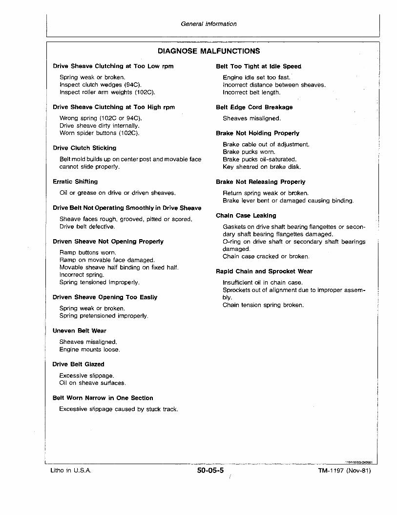
General Information
DIAGNOSE MALFUNCTIONS
Drive Sheave Clutching at Too Low rpm
Spring weak or broken.Inspect clutch wedges (94C).Inspect roller arm weights (102C).
Drive Sheave Clutching at Too High rpm
Wrong spring (102C or 94C).Drive sheave dirty internally.Worn spider buttons (102C).
Drive Clutch Sticking
Belt mold builds up on center post and movable facecannot slide properly.
Erratic Shifting
Oil or grease on drive or driven sheaves.
Drive Belt Not Operating Smoothly in Drive Sheave
Sheave faces rough, grooved, pitted or scored.Drive belt defective.
Driven Sheave Not Opening Properly
Ramp buttons worn.Ramp on movable face damaged.Movable sheave half binding on fixed half.Incorrect spring.Spring tensioned improperly.
Driven Sheave Opening Too Easily
Spring weak or broken.Spring pretensioned improperly.
Uneven Belt Wear
Sheaves misaligned.Engine mounts loose.
Drive Belt Glazed
Excessive slippage.Oil on sheave surfaces.
Belt Worn Narrow in One Section
Excessive slippage caused by stuck track.
Belt Too Tight at Idle Speed
Engine idleset too fast.Incorrect distance between sheaves.Incorrect belt length.
Belt Edge Cord Breakage
Sheaves misaligned.
Brake Not Holding Properly
Brake cable out of adjustment.Brake pucks worn.Brake pucks oil-saturated.Key sheared on brake disk.
Brake Not Releasing Properly
Return spring weak or broken.Brake lever bent or damaged causing binding.
Chain Case Leaking
Gaskets on drive shaft bearing flangettes or secondary shaft bearing flangettes damaged.O-ring on drive shaft or secondary shaft bearingsdamaged.Chain case cracked or broken.
Rapid Chain and Sprocket Wear
Insufficient oil in chain case.Sprockets out of alignment due to improper assembly.Chain tension spring broken.
1197/50051/240981
Litho in U.S.A. 50-05-5 TM-1197 (Nov-81)
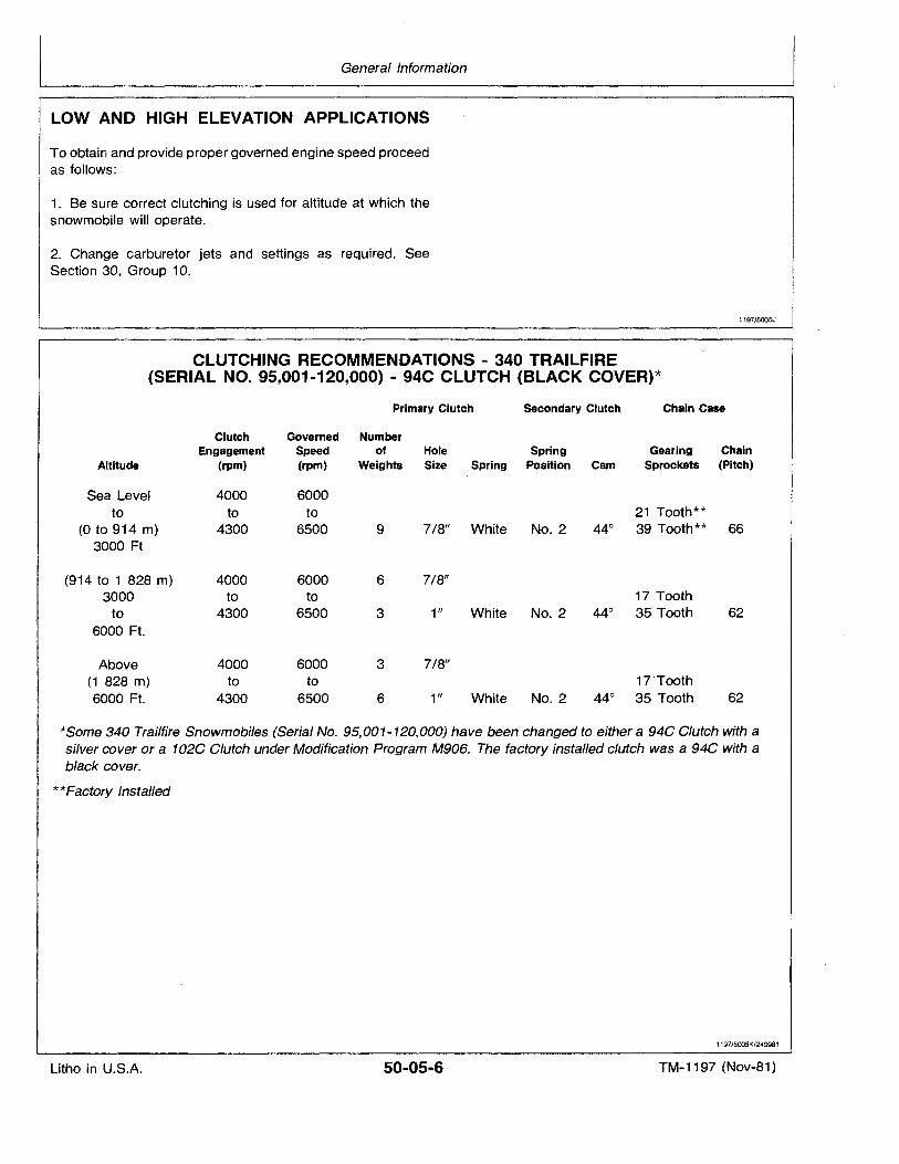
General Information
LOW AND HIGH .ELEVATION APPLICATIONS
To obtain and provide proper governed engine speed proceedas follows:
1. Be sure correct clutching is used for altitude at which thesnowmobile will operate.
2. Change carburetor jets and settings as required. SeeSection 30, Group 10.
1197/5005J
CLUTCHING RECOMMENDATIONS - 340 TRAILFIRE(SERIAL NO. 95,001-120,000) - 94C CLUTCH (BLACK COVER)*
Primary Clutch Secondary Clutch Chain Case
Clutch Governed NumberEngagement Speed of Hole Spring Gearing Chain
Altitude (rpm) (rpm) Weights Size Spring Position Cam Sprockets (Pitch)
Sea Level 4000 6000to to to 21 Tooth**
(0 to 914 m) 4300 6500 9 7/8" White No. 2 44° 39 Tooth** 663000 Ft
(914 to 1 828 m) 4000 6000 6 7/8"3000 to to 17 Tooth
to 4300 6500 3 1" White No. 2 44° 35 Tooth 626000 Ft.
Above 4000 6000 3 7/8"(1 828 m) to to 17'Tooth6000 Ft. 4300 6500 6 1" White No. 2 44° 35 Tooth 62
*Some 340 Trailfire Snowmobiles (Serial No. 95,001-120,000) have been changed to either a 94C Clutch with asilver cover or a 102C Clutch under Modification Program M906. The factory installed clutch was a 94C with ablack cover.
**Factory Installed
1197/5005K/240981
Litho in U.S.A. 50-05-6 TM-1197 (Nov-81)
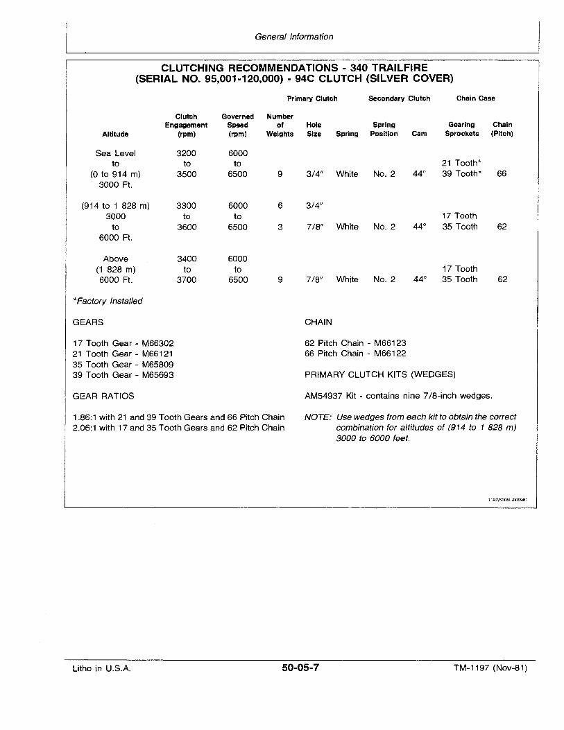
General Information
CLUTCHING RECOMMENDATIONS - 340 TRAILFIRE(SERIAL NO. 95,001-120,000) - 94C CLUTCH (SILVER COVER)
Primary Clutch Secondary Clutch Chain Case
Clutch Governed NumberEngagement Speed of Hole Spring Gearing Chain
Altitude (rpm) (rpm) Weights Size Spring Position Cam Sprockets (Pitch)
Sea Level 3200 6000to to to 21 Tooth*
(0 to 914 m) 3500 6500 9 3/4" White No. 2 44° 39 Tooth* 663000 Ft.
(914 to 1 828 m) 3300 6000 6 3/4"3000 to to 17 Tooth
to 3600 6500 3 7/8" White No. 2 44° 35 Tooth 626000 Ft.
Above 3400 6000(1 828 rn) to to 17 Tooth6000 Ft. 3700 6500 9 7/8" White No. 2 44° 35 Tooth 62
*Factory Installed
GEARS
17 Tooth Gear - M6630221 Tooth Gear - M6612135 Tooth Gear - M6580939 Tooth Gear - M65693
GEAR RATIOS
1.86:1 with 21 and 39 Tooth Gears and 66 Pitch Chain2.06:1 with 17 and 35 Tooth Gears and 62 Pitch Chain
CHAIN
62 Pitch Chain - M6612366 Pitch Chain - M66122
PRIMARY CLUTCH KITS (WEDGES)
AM54937 Kit - contains nine 7/8-inch wedges.
NOTE: Use wedges from each kit to obtain the correctcombination for altitudes of (914 to 1 828 m)3000 to 6000 feet.
1197/5005L1000981
Litho in U.S.A. 50-05·7 TM-1197 (Nov-81)
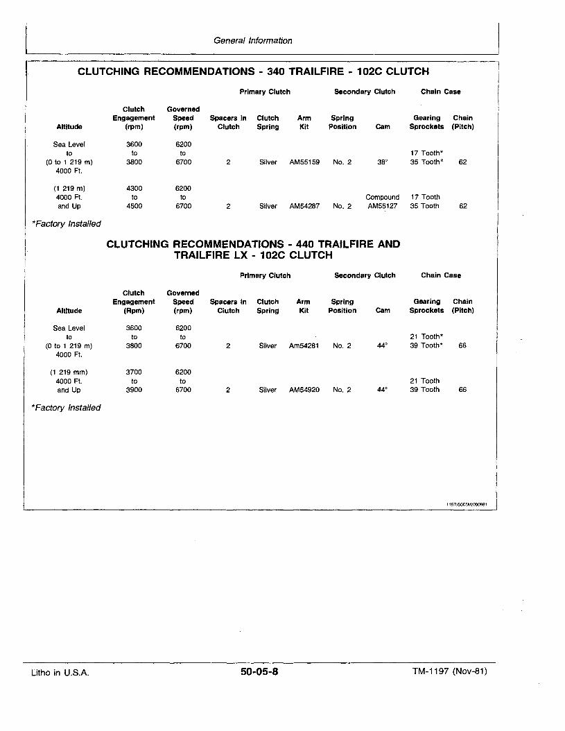
General Information
CLUTCHING RECOMMENDATIONS - 340 TRAILFIRE - 102C CLUTCH
Primary Clutch Secondary Clutch Chain Case
Clutch GovernedEngagement Spee~ Spacers in Clutch Arm Spring Gearing Chain
Altitude (rpm) (rpm) Clutch Spring Kit Position Cam Sprockets (Pitch)
Sea Level 3600 6200to to to 17 Tooth*
(0 to 1 219 m) 3800 6700 2 Silver AM55159 No. 2 38° 35 Tooth* 624000 Ft.
(1 219 m) 4300 62004000 Ft. to to Compound 17 Toothand Up 4500 6700 2 Silver AM54287 No. 2 AM55127 35 Tooth 62
*Factory Installed
CLUTCHING RECOMIYIENDATIONS - 440 TRAILFIRE ANDTRAILFIRE LX - 102C CLUTCH
Primary Clutch Secondary Clutch Chain Case
Clutch GovernedEngagement Speed Spacers in Clutch Arm Spring Gearing Chain
Altitude (Rpm) (rpm) Clutch Spring Kit Position Cam Sprockets (Pitch)
Sea Level 3600 6200to to to 21 Tooth*
(0 to 1 219 m) 3800 6700 2 Silver Am54281 No. 2 44° 39 Tooth* 664000 Ft.
(1 219 mm) 3700 62004000 Ft. to to 21 Toothand Up 3900 6700 2 Silver AM54920 No. 2 44° 39 Tooth 66
*Factory Installed
1197/5005M/000981
Litho in U.S.A. 50-05-8 TM-1197 (Nov-81)
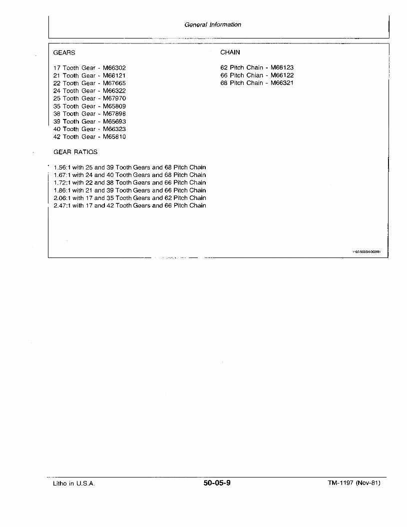
GEARS
17 Tooth Gear - M6630221 Tooth Gear - M6612122 Tooth Gear - M6766524 Tooth Gear - M6632225 Tooth Gear - M6797035 Tooth Gear - M6580938 Tooth Gear - M6789839 Tooth Gear - M6569340 Tooth Gear - M6632342 Tooth Gear - M65810
GEAR RATIOS
General Information
CHAIN
62 Pitch Chain - M6612366 Pitch Chian - ,M6612268 Pitch Chain - M66321
1.56:1 with 25 and 39 Tooth Gears and 68 Pitch Chain1.67:1 with 24 and 40 Tooth Gears and 68 Pitch Chain1.72:1 with 22 and 38 Tooth Gears and 66 Pitch Chain1.86:1 with 21 and 39 Tooth Gears and 66 Pitch Chain2.06:1 with 17 and 35 Tooth Gears and 62 Pitch Chain2.47:1 with 17 and 42 Tooth Gears and 66 Pitch Chain
1197/5005N/000981
Litho in U.S.A. 50-05-9 TM-1197 (Nov-81)

Litho in U.S.A.
General Information
50-05-10 TM-1197 (Nov-81)
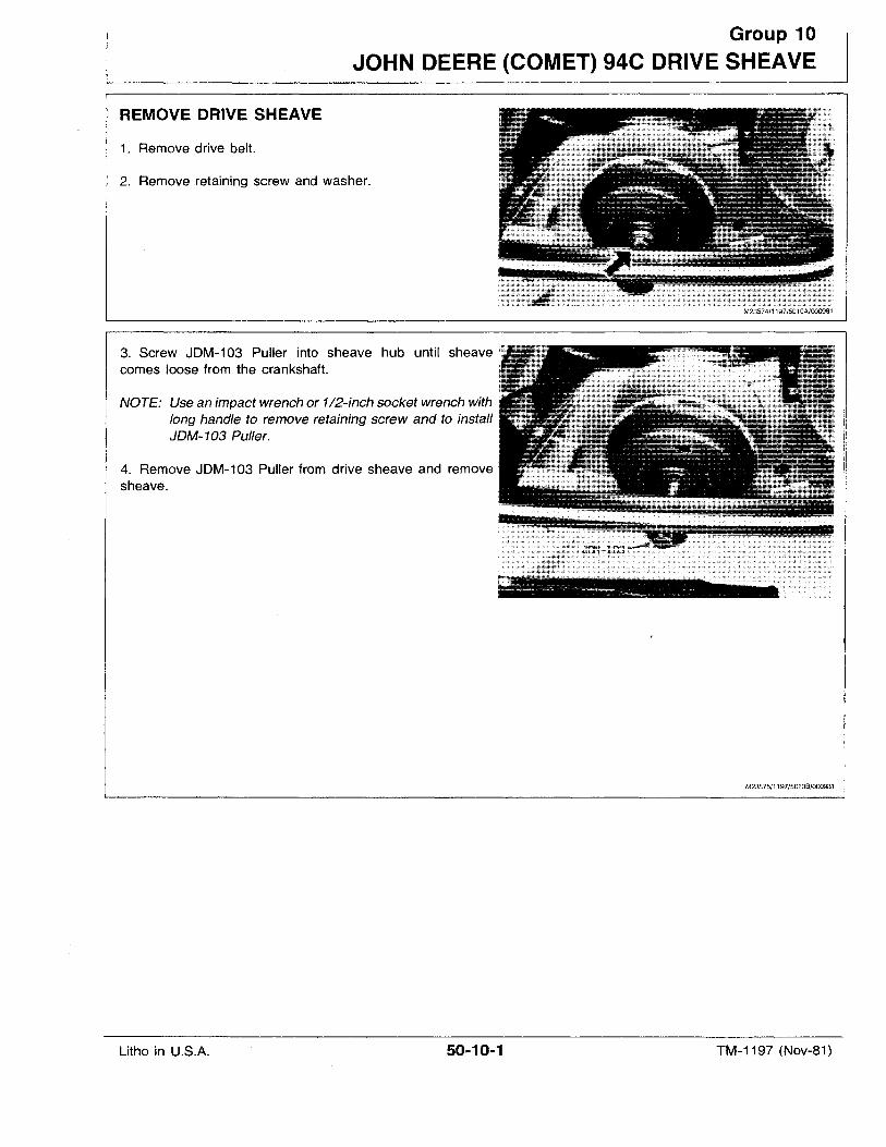
Group 10
JOHN DEERE (COMET) 94C DRIVE SHEAVE
REMOVE DRIVE SHEAVE
1. Remove drive belt.
2. Remove retaining screw and washer.
M23574/1197/5010A/000981
3. Screw JDM-103 Puller into sheave hub until sheavecomes loose from the crankshaft.
NOTE: Use an impact wrench or 1/2-inch socket wrench withlong handle to remove retaining screw and to installJDM-103 Puller.
4. Remove JDM-103 Puller from drive sheave and removesheave.
M23575/1197/5010B/000981
Litho in U.S.A. 50-10-1 TM-1197 (Nov-81)
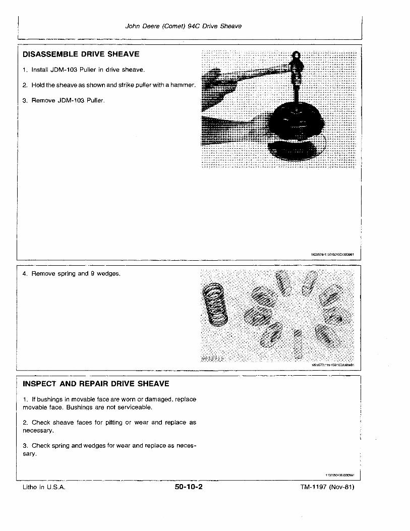
John Deere (Comet) 94C Drive Sheave
DISASSEMBLE DRIVE SHEAVE
1. Install JDM-103 Puller in drive sheave.
2. Hold the sheave as shown and strike puller with a hammer.
3. Remove JDM-103 Puller.
4. Remove spring and 9 wedges.
INSPECT AND REPAIR DRIVE SHEAVE
1. If bushings in movable face are worn or damaged, replacemovable face. Bushings are not serviceable.
2. Check sheave faces for pitting or wear and replace asnecessary.
3. Check spring and wedges for wear and replace as necessary.
M23576/1197/501OC/000981
M23577/1197/50100/000981
1197/5010E/000981
Litho in U.S.A. 50-10-2 TM-1197 (Nov-81)
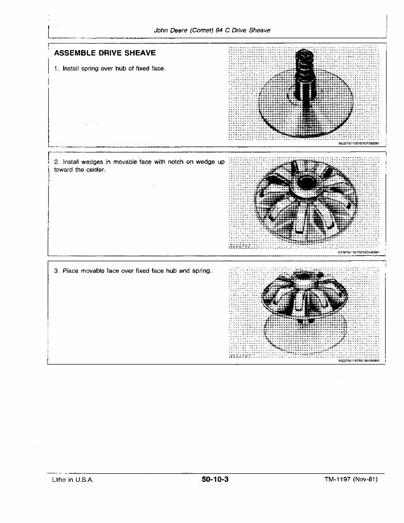
John Deere (Comet) 94 C Drive Sheave
ASSEMBLE DRIVE SHEAVE
1. Install spring over hub of fixed face.
2. Install wedges in movable face with notch on wedge uptoward the center.
3. Place movable face over fixed face hub and spring.
M22579/1197/5010F/000981
Litho in U.S.A. 50-10-3 TM-1197 (Nov-81)
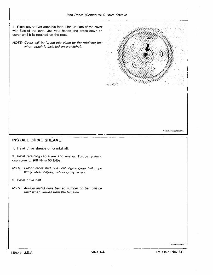
John Deere (Comet) 94 C Drive Sheave
4. Place cover over movable face. Line up flats of the coverwith flats of the post. Use your hands and press down oncover until it is retained on the post.
NOTE: Cover will be forced into place by the retaining boltwhen clutch is installed on crankshaft.
INSTALL DRIVE SHEAVE
1. Install drive sheave on crankshaft.
2. Install retaining cap screw and washer. Torque retainingcap screw to (68 N·m) 50 ft-Ibs.
NOTE: Pull on recoil start rope until dogs engage. Hold ropefirmly while torquing retaining cap screw.
3. Install drive belt.
NOTE: Always install drive belt so number on belt can beread when viewed from the left side.
M235BO/1197/50101/0009B1
1197/501OJ/000981
Litho in U.S.A. 50-10-4 TM-1197 (Nov-81)
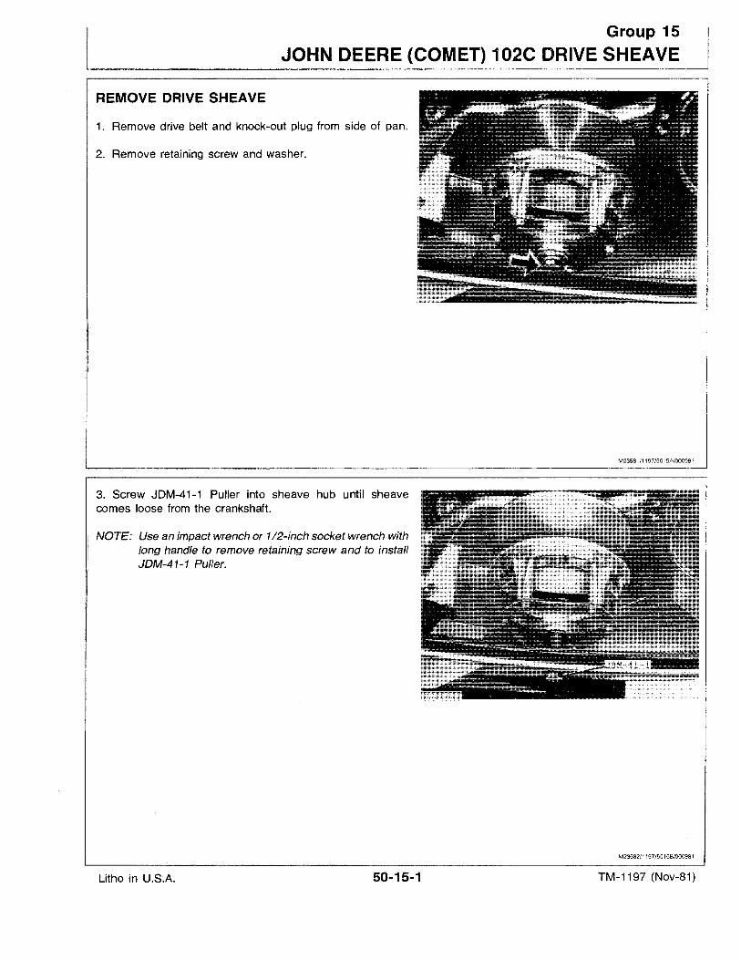
Group 15
JOHN DEERE (COMET) 102C DRIVE SHEAVE
REMOVE DRIVE SHEAVE
1. Remove drive belt and knock-out plug from side of pan.
2. Remove retaining screw and washer.
M23581/1197/5015A/OO0981
3. Screw JDM-41-1 Puller into sheave hub until sheavecomes loose from the crankshaft.
NOTE: Use an impact wrench or 1/2-inch socket wrench withlong handle to remove retaining screw and to installJDM-41-1 Puller.
M23582/1197/5015B/000981
Litho in U.S.A. 50-15-1 TM-1197 (Nov-81)
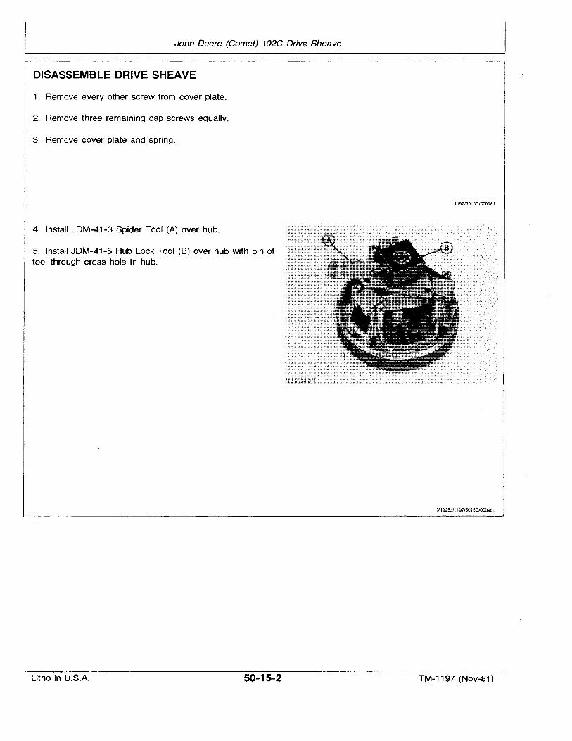
John Deere (Comet) 102C Drive Sheave
DISASSEMBLE DRIVE SHEAVE
1. Remove every other screw from cover plate.
2. Remove three remaining cap screws equally.
3. Remove cover plate and spring.
1197/501SC/000981
4. Install JDM-41-3 Spider Tool (A) over hub.
5. Install JDM-41-5 Hub Lock Tool (8) over hub with pin oftool through cross hole in hub.
M19253/1197/S015D/000981
Litho in U.S.A. 50-15-2 TM-1197 (Nov-81)
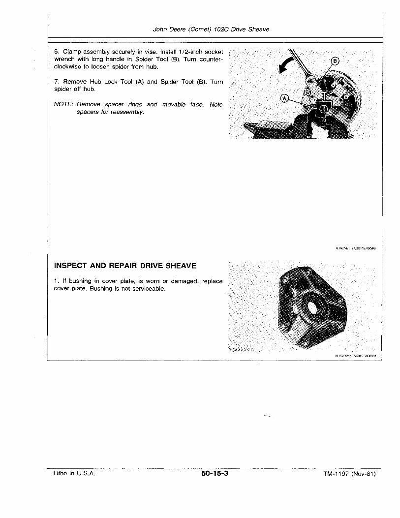
John Deere (Comet) 102C Drive Sheave
6. Clamp assembly securely in vise. Install 1/2-inch socketwrench with long handle in Spider Tool (B). Turn counterclockwise to loosen spider from hub.
7. Remove Hub Lock Tool (A) and Spider Tool (B). Turnspider off hub.
NOTE: Remove spacer rings and movable face. Notespacers for reassembly.
INSPECT AND REPAIR DRIVE SHEAVE
1. If bushing in cover plate, is worn or damaged, replacecover plate. Bushing is not serviceable.
M19254/1197/S01SE/000981
M1925S/1197/S015F/000981
Litho in U.S.A. 50-15-3 TM-1197 (Nov-81)
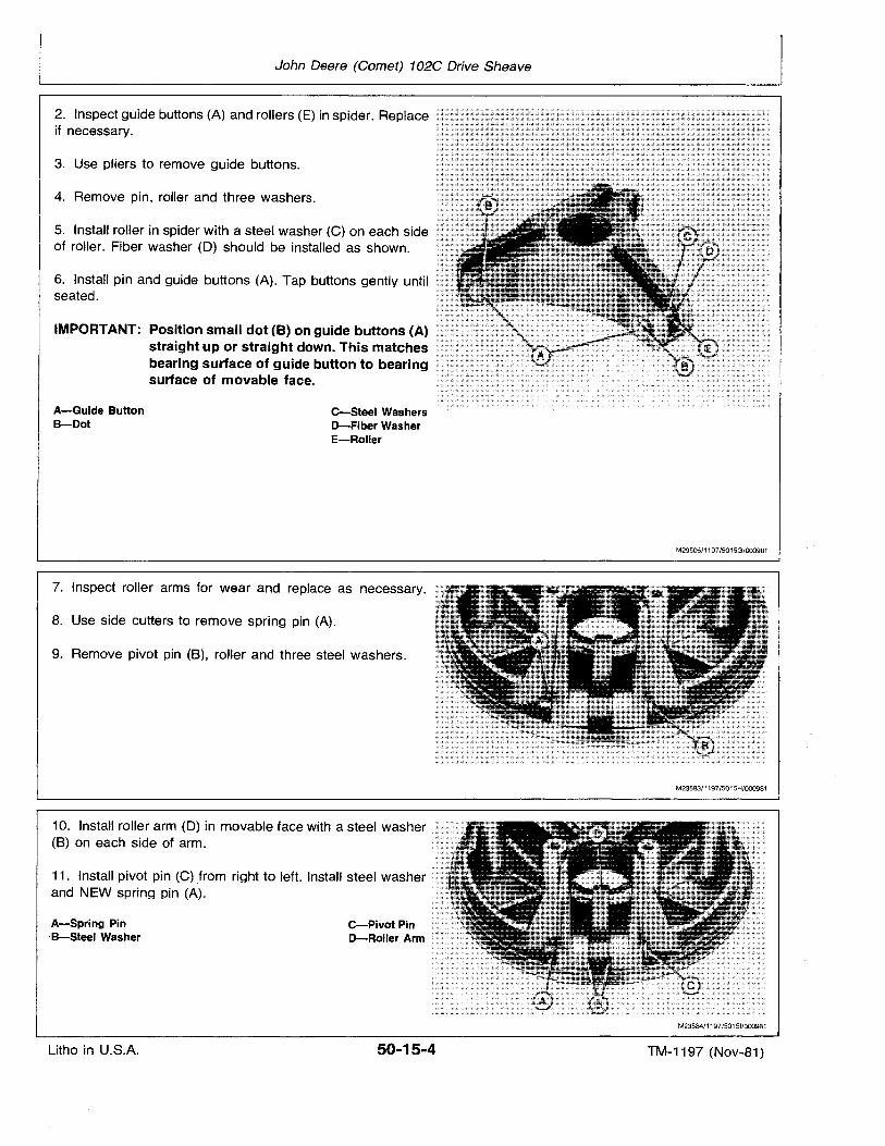
John Deere (Comet) 102C Drive Sheave
4. Remove pin, roller and three washers.
3. Use pliers to remove guide buttons.
6. Install pin and guide buttons (A). Tap buttons gently untilseated.
C-Steel WashersD-Fiber WasherE-Roller
5. Install roller in spider with a steel washer (C) on each sideof roller. Fiber washer (D) should be installed as shown.
2. Inspect guide buttons (A) and rollers (E) in spider. Replaceif necessary.
IMPORTANT: Position small dot (B) on guide buttons (A)straight up or straight down. This matchesbearing surface of guide button to bearingsurface of movable face.
A-Guide ButtonB-Dot
M29506/1197/5015G/000981
9. Remove pivot pin (B), roller and three steel washers.
8. Use side cutters to remove spring pin (A).
7. Inspect roller arms for wear and replace as necessary.
C-Pivot PinD-Roller Arm
10. Install roller arm (D) in movable face with a steel washer(B) on each side of arm.
11. Install pivot pin (C) from right to left. Install steel washerand NEW spring pin (A).
A-Spring Pin'S-Steel Washer
M235B4/1197/50151/000981
Litho in U.S.A. 50-15-4 TM-1197 (Nov-81)
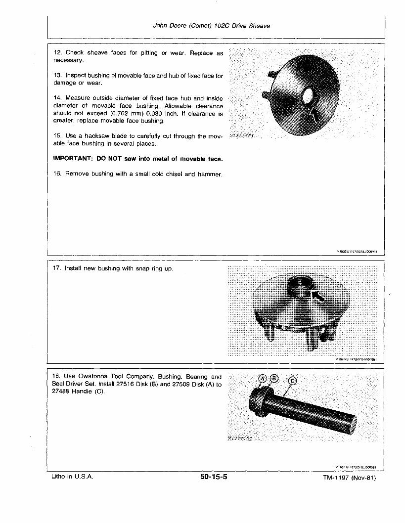
John Deere (Comet) 102C Drive Sheave
12. Check sheave faces for pitting or wear. Replace asnecessary.
13. Inspect bushing of movable face and hub of fixed face fordamage or wear.
14. Measure outside diameter of fixed face hub and insidediameter of movable face bushing. Allowable clearanceshould not exceed (0.762 mm) 0.030 inch. If clearance isgreater, replace movable face bushing.
15. Use a hacksaw blade to carefully cut through the movable face bushing in several places.
IMPORTANT: DO NOT saw into metal of movable face.
16. Remove bushing with a small cold chisel and hammer.
17. Install new bushing with snap ring up.
18. Use Owatonna Tool Company, Bushing, Bearing andSeal Driver Set. Install 27516 Disk (B) and 27509 Disk (A) to27488 Handle (C).
M19259/1197/5015J/000981
M19260/1197/5015K/000981
M19261/1197/501511000981
Litho in U.S.A. 50-15-5 TM-1197 (Nov-81)
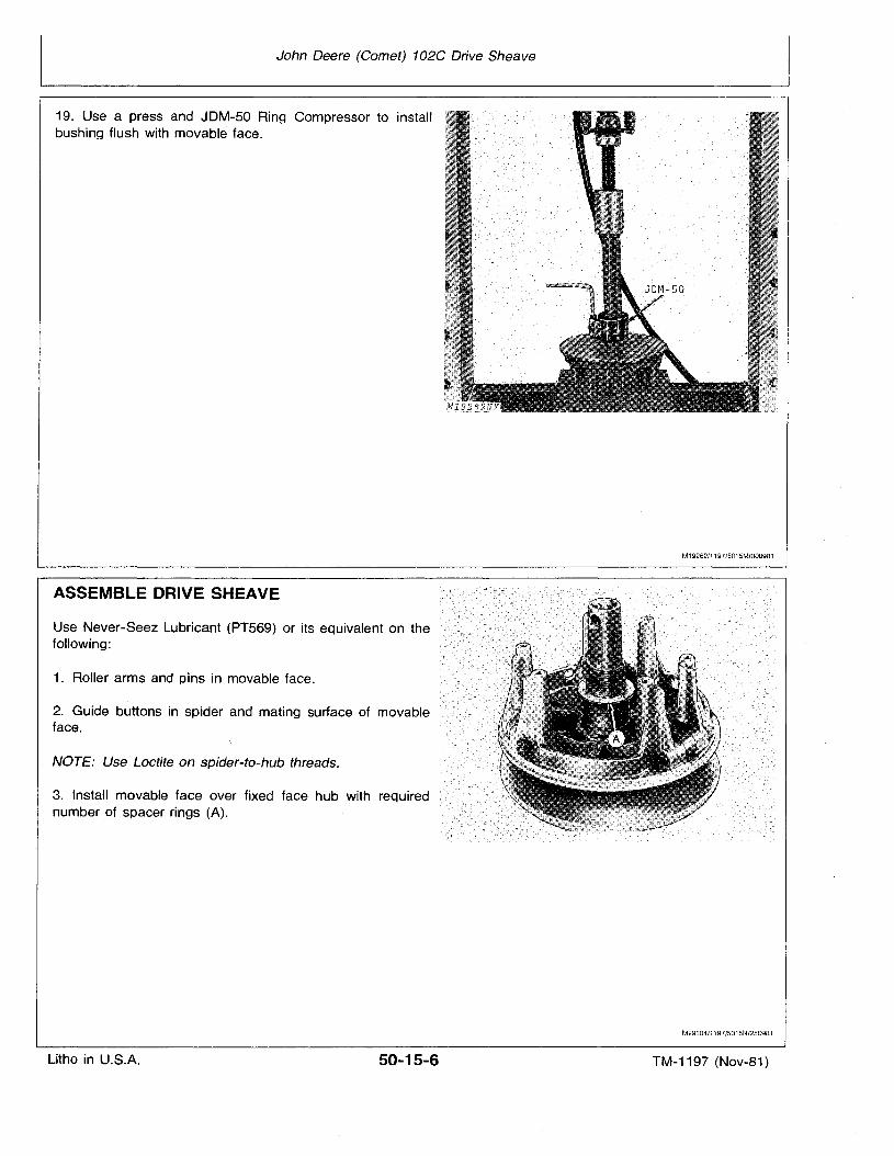
John Deere (Comet) 102C Drive Sheave
19. Use a press and JDM-50 Ring Compressor to installbushing flush with movable face.
ASSEMBLE DRIVE SHEAVE
Use Never-Seez Lubricant (PT569) or its equivalent on thefollowing:
1. Roller arms and pins in movable face.
2. Guide buttons in spider and mating surface of movableface.
NOTE: Use Loctite on spider-to-hub threads.
3. Install movable face over fixed face hub with requirednumber of spacer rings (A).
M19262/1197/5015M/000981
M29304/1197/5015N/250981
Litho in U.S.A. 50-15-6 TM-1197 (Nov-81)
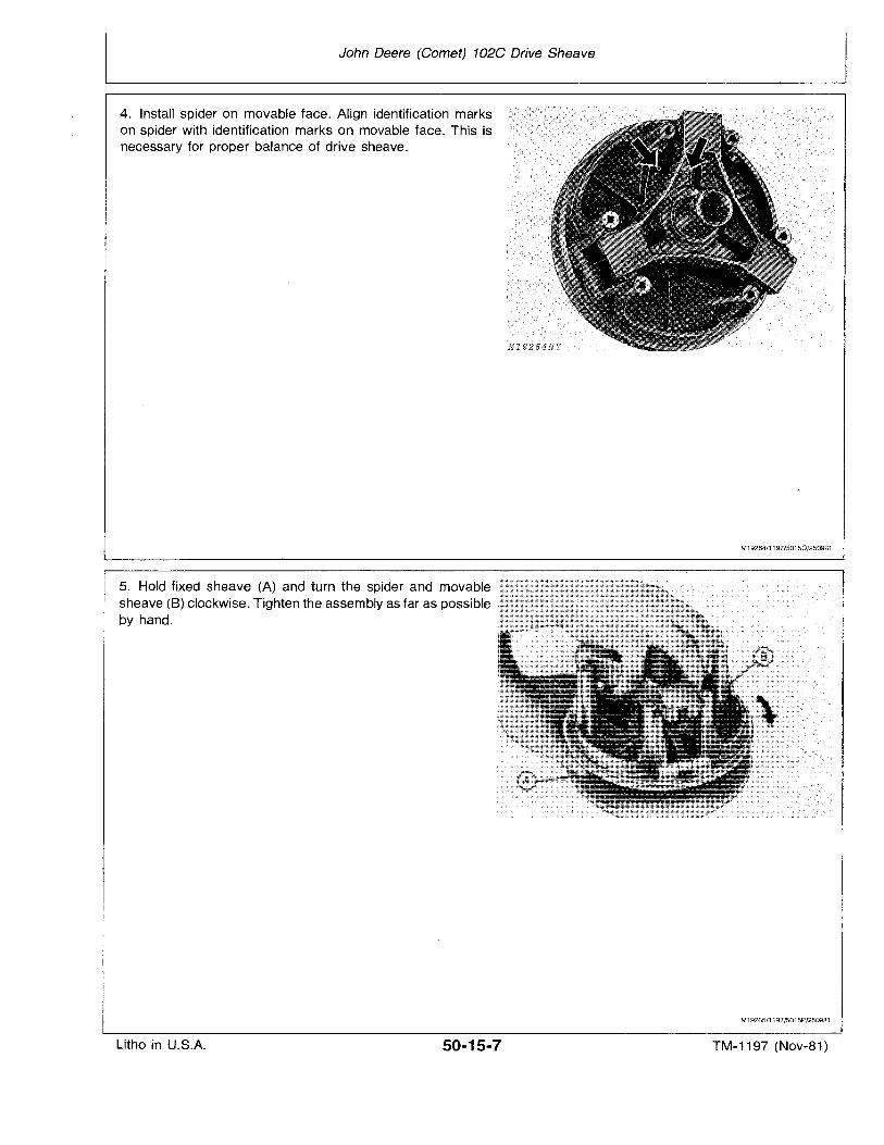
John Deere (Comet) 102C Drive Sheave
4. Install spider on movable face. Align identification markson spider with identification marks on movable face. This isnecessary for proper balance of drive sheave.
5. Hold fixed sheave (A) and turn the spider and movablesheave (8) clockwise. Tighten the assembly as far as possibleby hand.
M19264/1197/50150/250981
M19265/1197/5015P/2509B1
Litho in U.S.A. 50-15-7 TM-1197 (Nov-81)
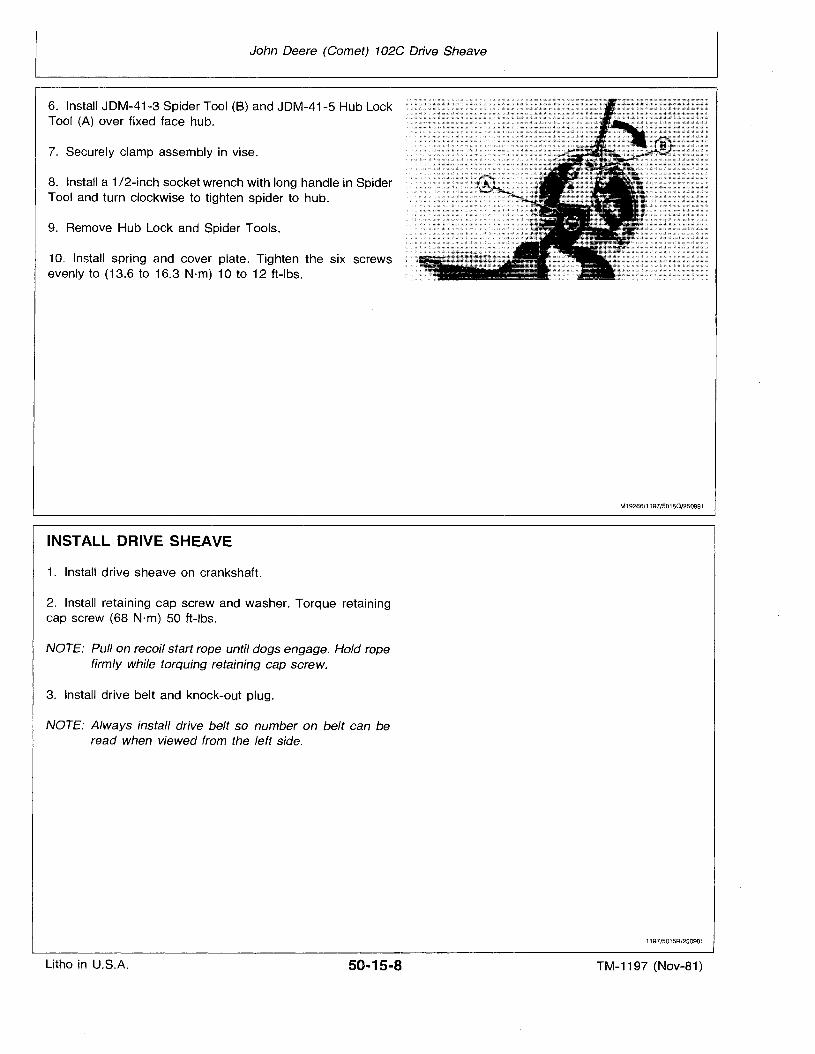
John Deere (Comet) 102C Drive Sheave
6. Install JDM-41-3 Spider Tool (8) and JDM-41-5 Hub LockTool (A) over fixed face hub.
7. Securely clamp assembly in vise.
8. Install a 1/2-inch socket wrench with long handle in SpiderTool and turn clockwise to tighten spider to hub.
9. Remove Hub Lock and Spider Tools.
10. Install spring and cover plate. Tighten the six screwsevenly to (13.6 to 16.3 N·m) 10 to 12 ft-Ibs.
INSTALL· DRIVE SHEAVE
1. Install drive sheave on crankshaft.
2. Install retaining cap screw and washer. Torque retainingcap screw (68 N·m) 50 ft-Ibs.
NOTE: Pull on recoil start rope until dogs engage. Hold ropefirmly while torquing retaining cap screw.
3. Install drive belt and knock-out plug.
NOTE: Always install drive belt so number on belt can beread when viewed from the left side.
M19266/1197/5015Q/250981
1197/5015R/250981
Litho in U.S.A. 50-15-8 TM-1197 (Nov-81)
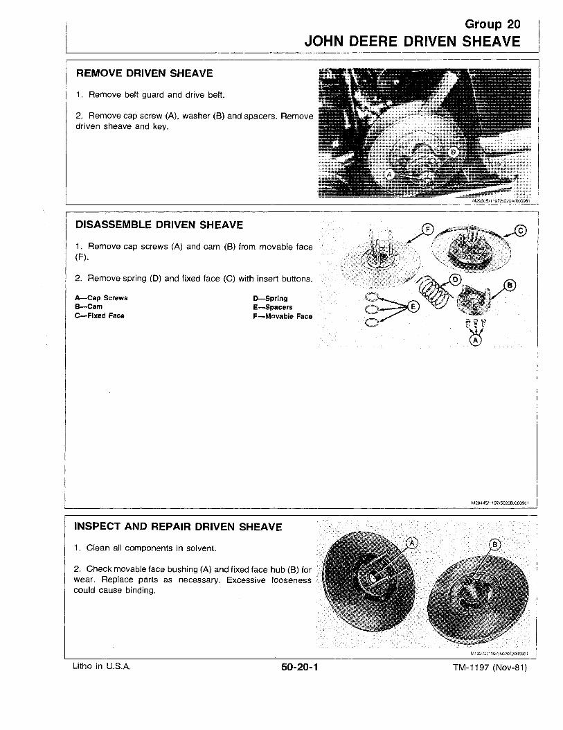
Group 20
JOHN DEERE DRIVEN SHEAVE
REMOVE DRIVEN SHEAVE
1. Remove belt guard and drive belt.
2. Remove cap screw (A), washer (B) and spacers. Removedriven sheave and key.
2. Remove spring (D) and fixed face (C) with insert buttons.
DISASSEMBLE DRIVEN SHEAVE
1. Remove cap screws (A) and cam (B) from movable face(F).
D-SpringE-SpacersF-Movable Face
A-Cap ScrewsB-CamC-Fixed Face
M28445/1197/5020B/000981
INSPECT AND REPAIR DRIVEN SHEAVE
1. Clean all components in solvent.
2. Check movable face bushing (A) and fixed face hub (B) forwear. Replace parts as necessary. Excessive loosenesscould cause binding.
M19272/1197/5020C/000981
Litho in U.S.A. 50-20-1 TM-1197 (Nov-81)
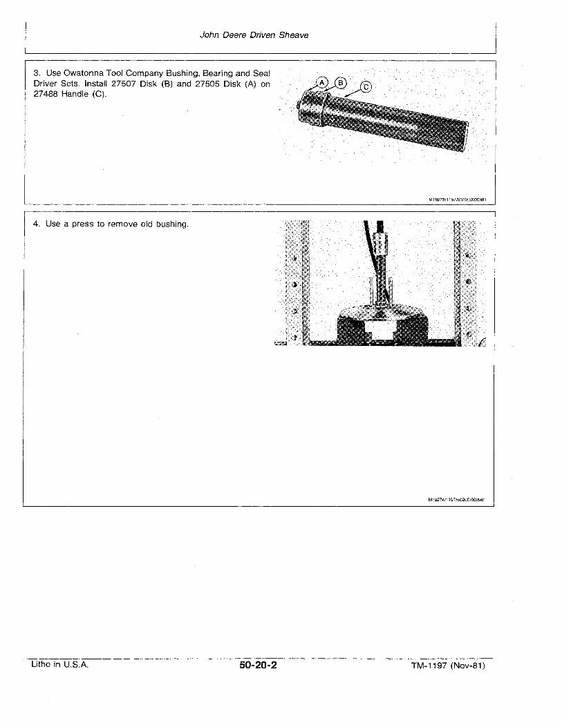
John Deere Driven Sheave
3. Use Owatonna Tool Company Bushing, Bearing and SealDriver Sets. Install 27507 Disk (B) and 27505 Disk (A) on27488 Handle (C).
4. Use a press to remove old bushing.
M19273/1197/5020D/OOO981
M19274/1197/5020E/OOO981
Litho in U.S.A. 50-20-2 TM-1197 (Nov-81)
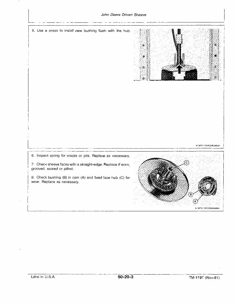
John Deere Driven Sheave
5. Use a press to install new bushing flush with the hub.
6. Inspect spring for cracks or pits. Replace as necessary.
7. Check sheave faces with a straight-edge. Replace if worn,grooved, scored or pitted.
8. Check bushing (8) in cam (A) and fixed face hub (C) forwear. Replace as necessary.
M19275/1197/5020F/000981
M19276/1197/5020G/000981
Litho in U.S.A. 50-20-3 TM-1197 (Nov-Bf )
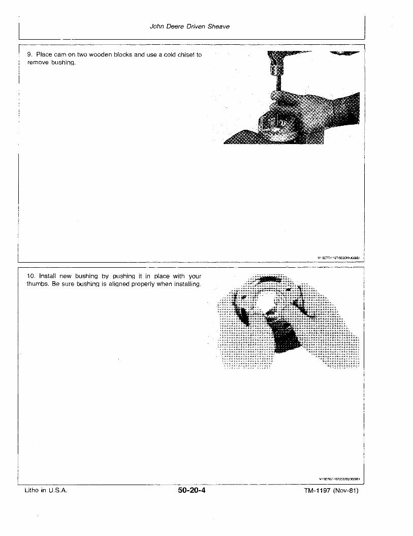
John Deere Driven Sheave
9. Place cam on two wooden blocks and use a cold chisel toremove bushing.
10. Install new bushing by pushing it in place with yourthumbs. Be sure bushing is aligned properly when installing.
M1927711 197/5020H/000981
M19278/1197/50201/000981
Litho in U.S.A. 50-20-4 TM-1197 (Nov-81)
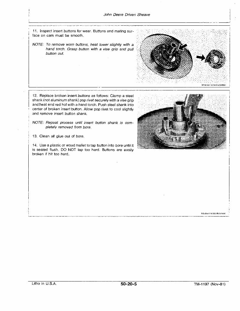
John Deere Driven Sheave
11. Inspect insert buttons for wear. Buttons and mating surface on cam must be smooth.
NOTE: To remove worn buttons, heat tower slightly with ahand torch. Grasp button with a vise grip and pullbutton out.
12. Replace broken insert buttons as follows: Clamp a steelshank (not aluminum shank) pop rivet securely with a vise gripand heat end red hot with a hand torch. Push steel shank intocenter of broken insert button. Allow pop rivet to cool slightlyand remove insert button shank.
NOTE: Repeat process until insert button shank is completely removed from bore.
13. Clean all glue out of bore.
14. Use a plastic or wood mallet to tap button into bore until itis seated flush. DO NOT tap too hard. Buttons are easilybroken if hit too hard.
M19279/1197/502OJ/000981
M28535/1197/5020K/071081
Litho in U.S.A. 50-20-5 TM-1197 (Nov-81)
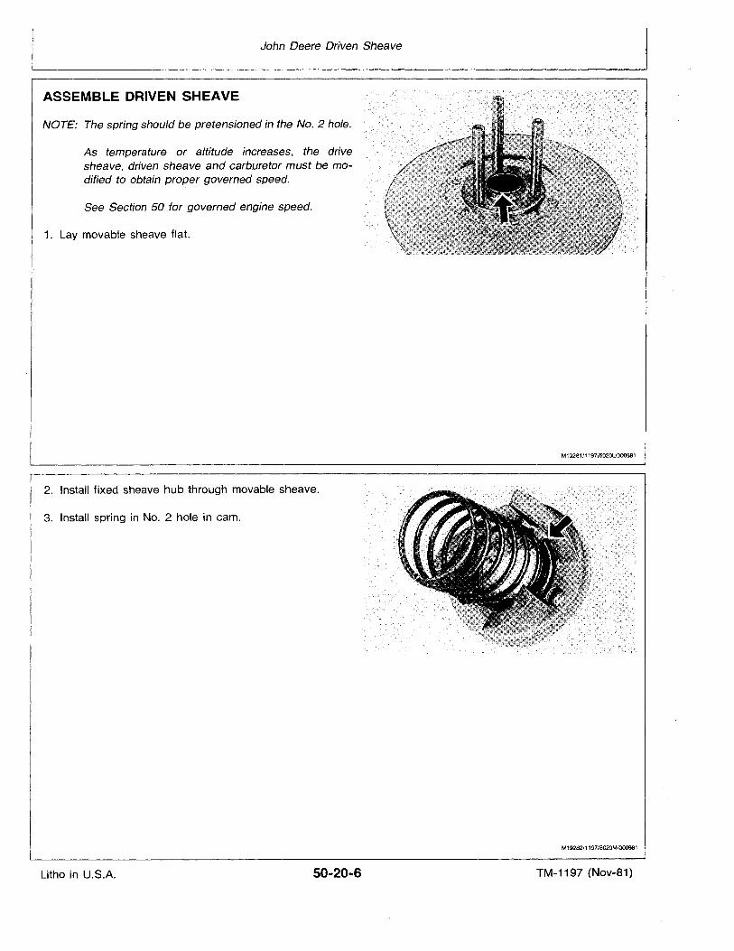
John Deere Driven Sheave
ASSEMBLE DRIVEN SHEAVE
NOTE: The spring should be pretensioned in the No.2 hole.
As temperature or altitude increases, the drivesheave, driven sheave and carburetor must be modified to obtain proper governed speed.
See Section 50 for governed engine speed.
1. Lay movable sheave flat.
2. Install fixed sheave hub through movable sheave.
3. Install spring in No.2 hole in cam.
M19281/1197/5020U000981
M19282/1197/5020M/0009B1
Litho in U.S.A. 50-20-6 TM-1197 (Nov-81)
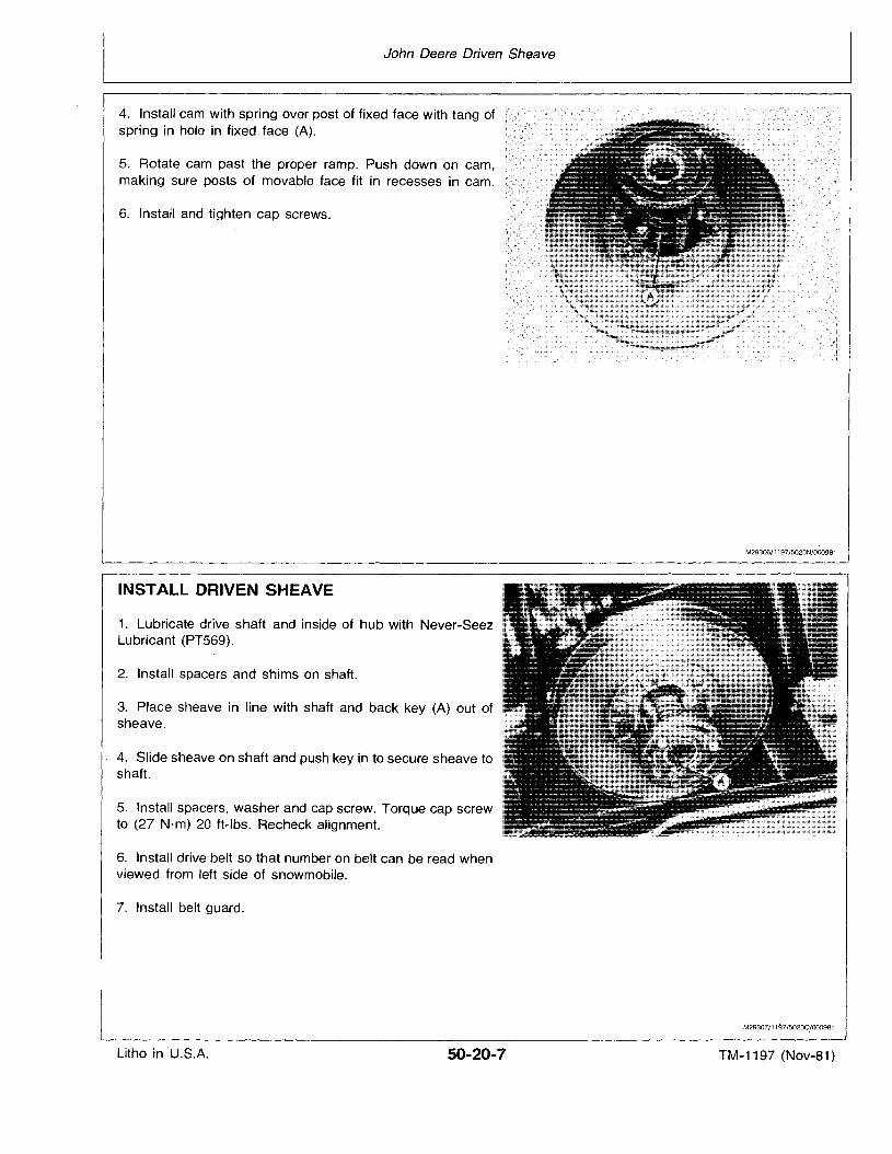
John Deere Driven Sheave
4. Install cam with spring over post of fixed face with tang ofspring in hole in fixed face (A).
5. Rotate cam past the proper ramp. Push down on cam,making sure posts of movable face fit in recesses in cam.
6. Install and tighten cap screws.
INSTALL DRIVEN SHEAVE
1. Lubricate drive shaft and inside of hub with Never-SeezLubricant (PT569).
2. Install spacers and shims on shaft.
3. Place sheave in line with shaft and back key (A) out ofsheave.
4. Slide sheave on shaft and push key in to secure sheave toshaft.
5. Install spacers, washer and cap screw. Torque cap screwto (27 N·m) 20 ft-Ibs. Recheck alignment.
6. Install drive belt so that number on belt can be read whenviewed from left side of snowmobile.
7. Install belt guard.
M29306/1197/5020N/000981
M29307/11~7/50200/000981
Litho in ·U.S.A. 50-20-7 TM-1197 (Nov-81)

Litho in U.S.A.
John Deere Driven Sheave
50-20-8 TM-1197 (Nov-81)
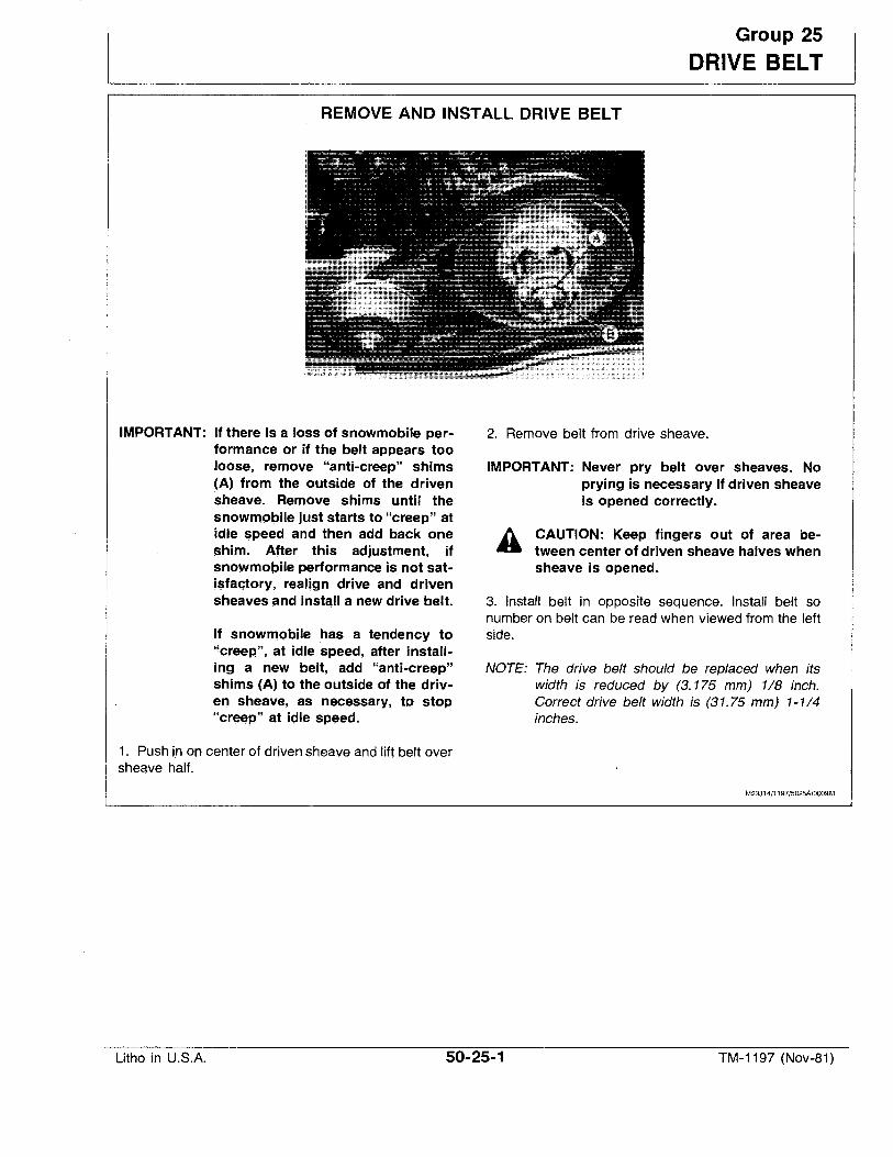
Group 25
DRIVE BELT
REMOVE AND INSTALL DRIVE BELT
IMPORTANT: If there is a loss of snowmobile performance or if the belt appears tooloose, remove "anti-creep" shims(A) from the outside of the drivensheave. Remove shims until thesnowmobile just starts to "creep" atidle speed and then add back oneshlm, After this adjustment, ifsnowrnoblle performance is not sati$fa(,ftory, real~gn drive and drivensheaves and inst~1I a new drive belt.
If snowmobile has a tendency to"creep", at idle speed, after installing a new belt, add "anti-creep"shims (A) to the outside of the drivell sheave, as necessary, to stop"creep" at idle speed.
1. Push ln on center of driven sheave and lift-belt oversheave half.
2. Remove belt from drive sheave.
IMPORTANT: Never pry belt over sheaves. Noprying is necessary if driven sheaveis opened correctly.
CAUTION: Keep fingers out of area between center of driven sheave halves whensheave is opened.
3. Install belt in opposite sequence. Install belt sonumber on belt can be read when viewed from the leftside.
NOTE: The drive belt should be replaced when itswidth is reduced by (3. 175 mm) 1/8 inch.Correct drive belt width is (31.75 mm) 1-1/4inches.
M23314/1197/5025A/000981
Litho in U.S.A. 50-25-1 TM-1197 (Nov-81)
Drive Belt
DRIVE BELT FUNCTIONS
Problem
Uneven belt wear on oneside only.
Belt glazed or has bakedappearance.
Belt worn excessively in topwidth.
Belt worn narrow in onesection.
Belt too tight at engine idle.
Belt disentegration.
Belt worn concave on sides.
Belt "flip-over" at highspeed.
Belt edge cord breakage.
Flex cracks between cogs.
Sheared cogs, compressionsection fractured or torn.
Litho in U.S.A.
Cause
Sheave misalignment.Loose engine base.
Insufficient pressure on beltsides.Excessive horsepower for beltand clutch.Oil on sheave surfaces.
Excessive slippage.Rough or scratched sheavesurfaces.Improper belt angle.
Excess slippage due to frozentrack or clutch not functioningproperly.
Idle speed too high.Incorrect belt length.Incorrect shims in secondary.
Excessive belt speed.
Excessive ride-out on drivesheave.
Sheave misalignment.Excessive belt speed.Excessive ride-out on drivesheave.
Sheave misalignment.Improper belt.
Belt worn out.
Improper belt.Belt rubbing stationary object.
50-25-2
Solution
Align sheaves.Replace or tighten base.
Check drive sheave for worn flyweights orclutch arms.Be sure correct clutch is being used.
Clean sheave surfaces.
Check drive sheave for smooth operation.Replace or repair sheaves.
Check alignment.
Rotate track by hand until free.Repair or replace clutch.
Reduce speed.Check belt.Add a shim.
Check engine speed at wide open throttle.
Repair or replace sheave. Belt too long.
Align sheaves.Reduce engine rpm.Belt too long.
Align sheaves.Check drive belt.
Replace belt.
Check belt.Check drive sheave.
1197/50258/000981
TM-1197 (Nov-81)
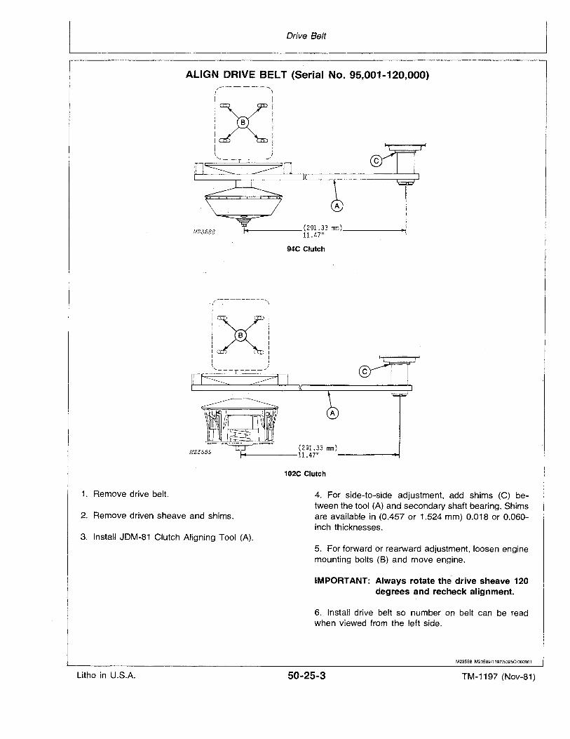
Drive Belt
ALIGN DRIVE BELT (Serial No. 95,001-120,000)
©
....- (291.33 mm) oolM
11.47"
t/------'"'\
I IIX'I II B II II II .. II I\ I
........ _- -_./
M23588
94C Clutch
/----------,.( \
I I:x:: . . :I B :I II· II II II ,\ J
......._---- -_/
(291.33 mm)....-..----11.47" -----..
102C Clutch
1. Remove drive belt.
2. Remove driven sheave and shims.
4. For side-to-side adjustment, add shims (C) between the tool (A) and secondary shaft bearing. Shimsare available in (0.457 or 1.524 mm) 0.018 or 0.060inch thicknesses.
3. Install JDM-81 Clutch Aligning Tool (A).5. For forward or rearward adjustment, loosen enginemounting bolts (B) and move engine.
IMPORTANT: Always rotate the drive sheave 120degrees and recheck alignment.
6. Install drive belt so number on belt can be readwhen viewed from the left side.
M23588 M23589/1197/5025C/000981
Litho in U.S.A. 50-25-3 TM-1197 (Nov-81)
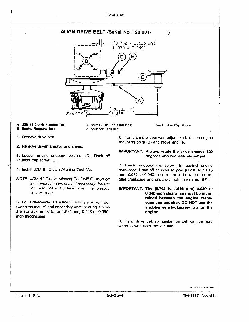
Drive Belt
ALIGN DRIVE BELT (Serial NOM 120,001- )
(0.762 - I.DIG mm)0.030 - 0.040 11
(291,33 mm)...----11.47 11
,----~, \
:¥em:I II B I
Iat' eml~ I'.."... - - - - --,'~~r------@i
I
II
•IA-JDM·81 Clutch Aligning ToolB-Engine Mounting Bolts
e-Shims (O.018 or 0.060 Inch)D-Snubber Lock Nut
E-Snubber Cap Screw
1. Remove drive belt.
2. Remove driven sheave and shims.
6. For forward or rearward adjustment, loosen enginemounting bolts (B) and move engine.
3. Loosen engine snubber lock nut (D). Back offsnubber cap screw (E).
IMPORTANT: Always rotate the drive sheave 120degrees and recheck alignment.
4. Install JDM-81 Clutch Aligning Tool (A).
NOTE: JDM-81 Clutch Aligning Tool will fit snug onthe primary sheave shaft. If necessary, tap thetool into place by hand over the primarysheave shaft.
5. For side-fa-side adjustment, add shims (C) between the tool (A) and secondary shaft bearing. Shimsare available in (0.457 or 1.524 mm) 0.018 or 0.060inch thicknesses.
7. Thread snubber cap screw (E) against enginecrankcase. Back off snubber to give (0.762 to 1.016mm) 0.030 to 0.040-inch clearance between the engine crankcase and snubber. Tighten lock nut (D).
IMPORTANT: The (0.762 to 1.016 mm) 0.030 toO.040-inch clearance must be maintained between the engine crankcase and snubber. DO NOT use thesnubber as a jackscrew to align theengine.
8. Install drive ·belt so number on belt can be readwhen viewed from the left side.
M26326/1197/5025D/250981
Litho in U.S.A. 50-25-4 TM-1197 (Nov-81)
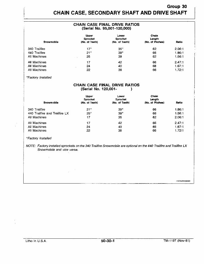
Group 30
CHAIN CASE, SECONDARY SHAFT AND DRIVE SHAFT
CHAIN CASE FINAL DRIVE RATIOS(Serial No. 95,001-120,000)
Upper Lower ChainSprocket Sprocket Length
Snowmobile (No. of Teeth) (No. of Teeth) (No. of Pitches) Ratio
340 Trailfire 17* 35* 62 2.06:1440 Trailfire 21* 39* 66 1.86:1All Machines 25 39 62 1.56:1
All Machines 17 42 66 2.47:1All Machines 24 40 68 1.67:1All Machines 22 38 66 1.72:1
*Factory Installed
,CHAIN CASE FINAL DRIVE RATIOS(Serial No. 120,001- )
Upper Lower ChainSprocket Sprocket Length
Snowmobile (No. of Teeth) (No. of Teeth) (No. of Pitches) Ratio
340 Trailfire 21* 39* 66 1.86:1440 Trailfire and Trailfire LX 25* 39* 68 1.56:1All Machines 17 35 62 2.06:1
All Machines 17 42 66 2.47:1All Machines 24 40 68 1.67:1All Machines 22 38 66 1.72:1
*Factory Installed
NOTE: Factory installed sprockets on the 340 Trailfire Snowmobile are optional on the 440 Trailfire and Trailfire LXSnowmobile and vice versa.
1197/5030A/000981
Litho in U.S.A. 50-30-1 TM-1197 (Nov-81)
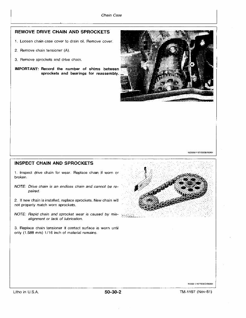
Chain Case
REMOVE DRIVE CHAIN AND SPROCKETS
1. Loosen chain case cover to drain oil. Remove cover.
2. Remove chain tensioner (A).
3. Remove sprockets and drive chain.
IMPORTANT: Record the number of shims betweensprockets and bearings for reassembly.
INSPECT CHAIN AND SPROCKETS
1. Inspect drive chain for wear. Replace chain if worn orbroken.
NOTE: Drive chain is an endless chain and cannot be repaired.
2. If new chain is installed, replace sprockets. New chain willnot properly match worn sprockets.
NOTE: Rapid chain and sprocket wear is caused by misalignment or lack of lubrication.
3. Replace chain tensioner if contact surface is worn untilonly (1.588 mm) 1/16 inch of material remains.
M29308/1197/5030B/000981
M23591/1197/503OC/000981
Litho in U.S.A. 50-30-2 TM-1197 (Nov-81)
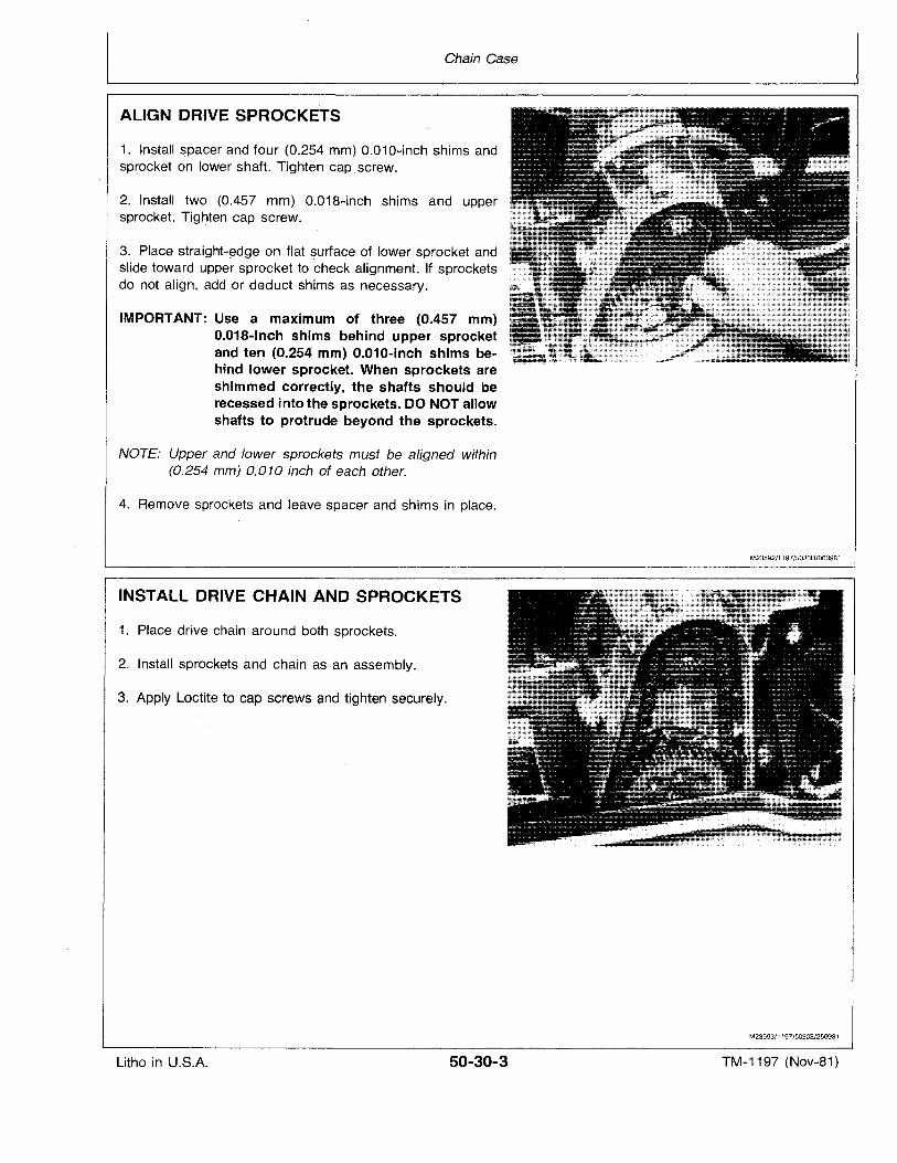
Chain Case
ALIGN DRIVE SPROCKETS
1. Install spacer and four (0.254 mm) 0.010-inch shims andsprocket on lower shaft. Tighten cap, screw.
2. Install two (0.457 mm) 0.018-inch shims and uppersprocket.,'Tighten cap screw.
3. Place straight-edge on flat surface of lower sprocket andslide toward upper sprocket to check alignment. If sprocketsdo not align, add or deduct shims as necessary.
IMPORTANT: Use a maximum of three (0.457 mm)0.018-inch shims behind upper sprocketand ten (0.254 mm) O.010-inch shims behind lower sprocket. When sprockets areshimmed correctly, the shafts should berecessed into the sprockets. DO NOT allowshafts to protrude beyond the sprockets.
NOTE: Upper and lower sprockets must be aligned within(0.254 mm) 0.010 inch of each other.
4. Remove sprockets and leave spacer and shims in place.
INSTALL DRIVE CHAIN AND SPROCKETS
1. Place drive chain around both sprockets.
2. ,Install sprockets and chain as an assembly.
3. Apply Loctite to cap screws and tighten securely.
M23592/1197/5030D/OO0981
M23593/1197/5030E/250981
Litho in U.S.A. 50-30-3 TM-1197 (Nov-81)
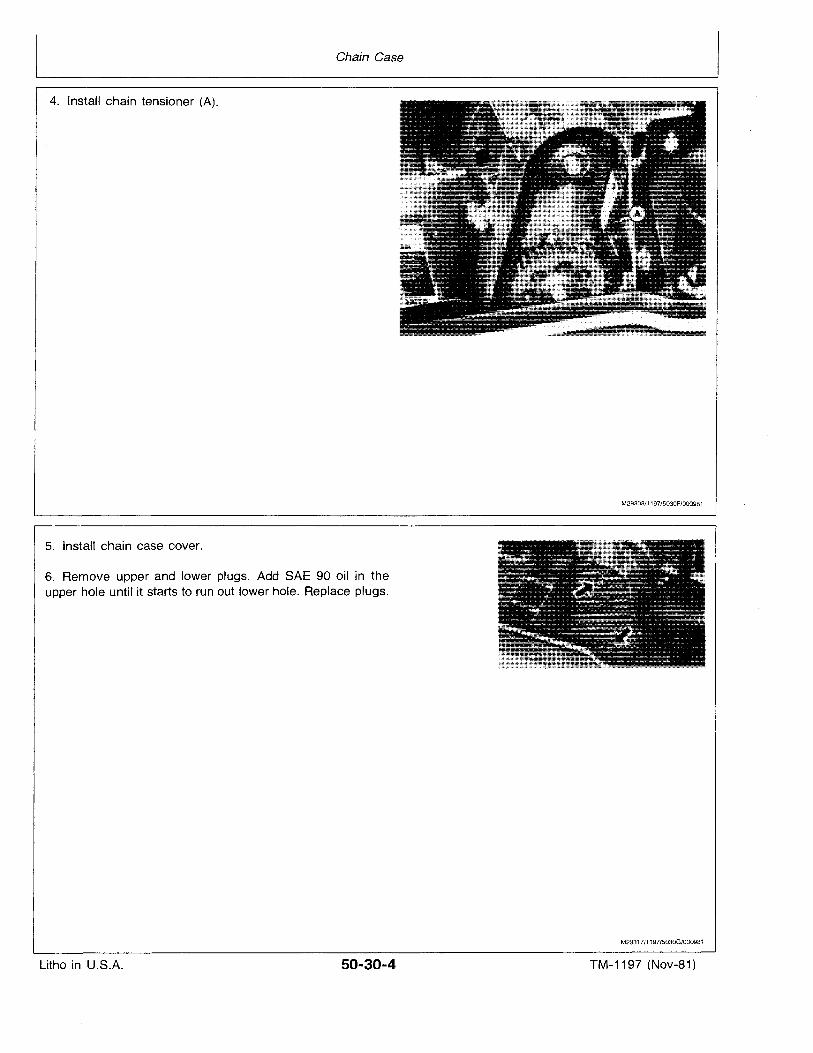
Chain Case
4. Install chain tensioner (A).
5. Install chain case cover.
6. Remove upper and lower plugs. Add SAE 90 oil in theupper hole until it starts to run out lower hole. Replace plugs.
M29308/1197/5030F/000981
M23317/1197/5030G/000981
Litho in U.S.A. 50-30-4 TM-1197 (Nov-81)
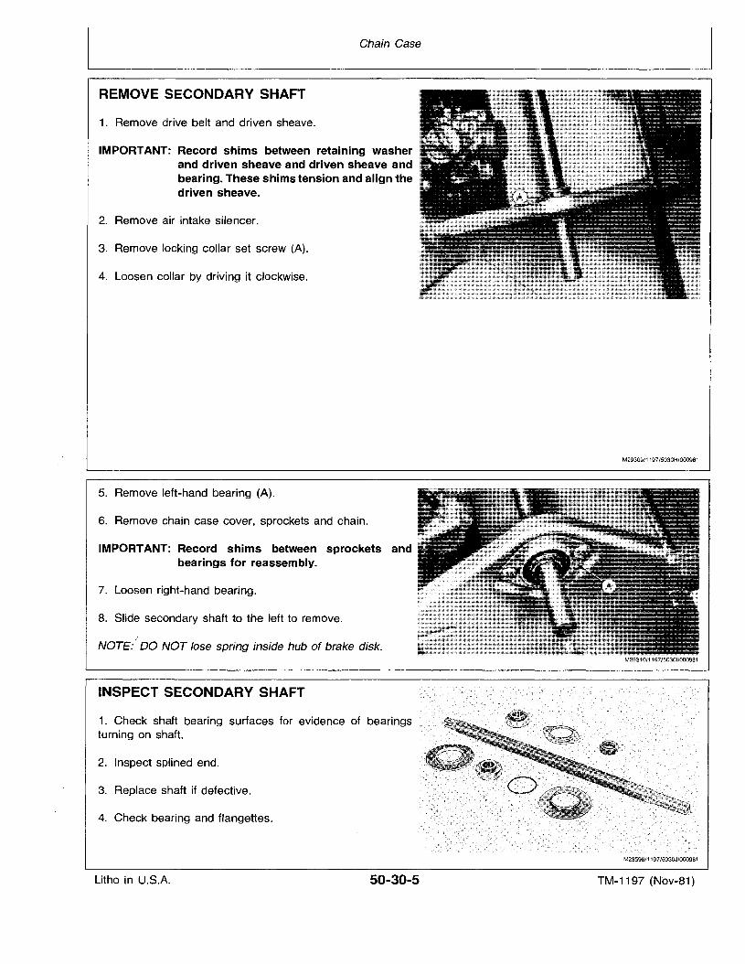
Chain Case
REMOVE SECONDARY SHAFT
1. Remove drive belt and driven sheave.
IMPORTANT: Record shims between retaining washerand driven sheave and driven sheave andbearing. These shims tension and align thedriven sheave.
2. Remove air intake silencer.
3. Remove locking collar set screw (A).
4. Loosen collar by driving it clockwise.
5. Remove left-hand bearing (A).
6. Remove chain case cover, sprockets and chain.
IMPORTANT: Record shims between sprockets andbearings for reassembly.
7. Loosen right-hand bearing.
8. Slide secondary shaft to the left to remove.
NOTE:·" DO NOT lose spring inside hub of brake disk.
INSPECT SECONDARY SHAFT
1. Check shaft bearing surfaces for evidence of bearingsturning on shaft.
2. Inspect splined end.
3. Replace shaft if defective.
4. Check bearing and flangettes.
M29309/1197/5030H/000981
M23596/1197/503OJ/000981
Litho in U.S.A. 50-30-5 TM-1197 (Nov-81)
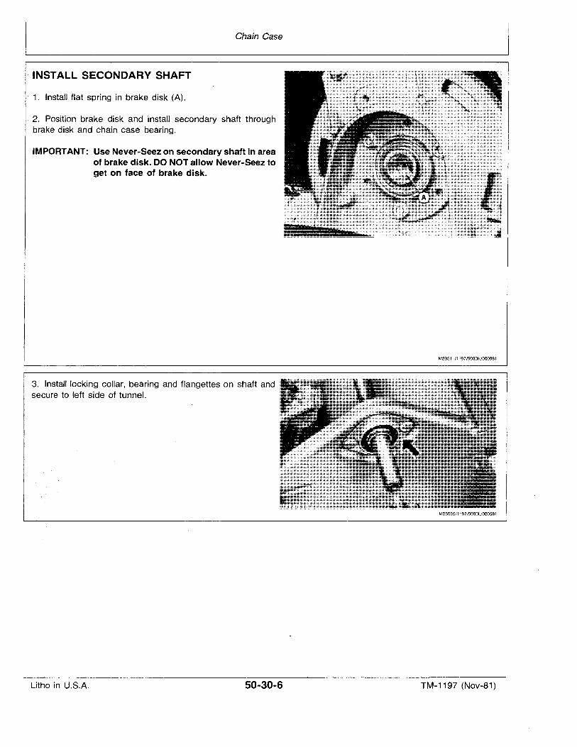
Chain Case
INSTALL SECONDARY SHAFT
. 1. Install flat spring in brake disk (A).
. 2. Position brake disk and install secondary shaft throughbrake disk and chain case bearing.
IMPORTANT: Use Never-Seez on secondary shaft in areaof brake disk. DO NOT allow Never-Seez toget on face of brake disk.
M29311/1197/5030K/000981
3. Install locking collar, bearing and flangettes on shaft andsecure to left side of tunnel.
M23595/1197/5030L/OOO981
Litho in U.S.A. 50-30-6 TM-1197 (Nov-81)
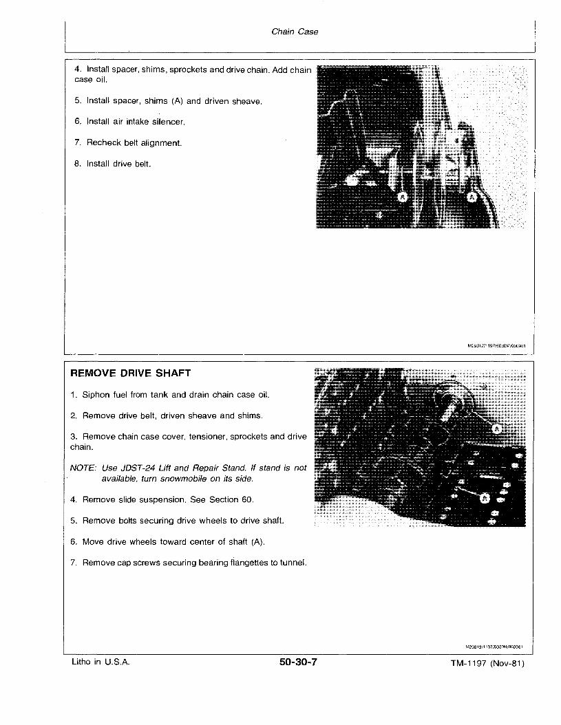
Chain Case
4. Install spacer, shims, sprockets and drive chain. Add chaincase oil.
5. Install spacer, shims (A) and driven sheave.
6. Install air intake silencer.
7. Recheck belt alignment.
8. Install drive belt.
REMOVE DRIVE SHAFT
1. Siphon fuel from tank and drain chain case oil.
2. Remove drive belt, driven sheave and shims.
3. Remove chain case cover, tensioner, sprockets and drivechain.
NOTE: Use JDST-24 Lift and Repair Stand. If stand is notavailable, turn snowmobile on its side.
4. Remove slide suspension. See Section 60.
5. Remove bolts securing drive wheels to drive shaft.
6. Move drive wheels toward center of shaft (A).
7. Remove cap screws securing bearing tlanqettes to tunnel.
M29312/1197/5030M/OOO981
M29313/1197/5030N/OOO981
Litho in U.S.A. 50-30-7 TM-1197 (Nov-81)
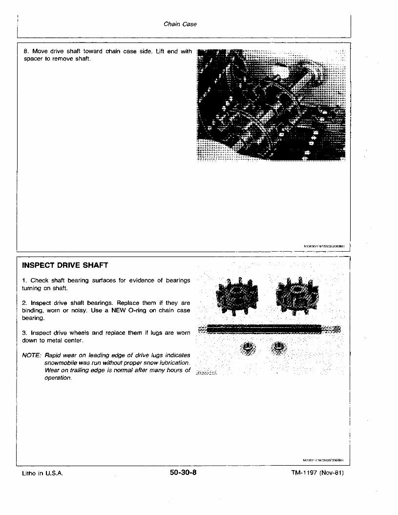
Chain Case
8. Move drive shaft toward chain case side. Lift end withspacer to remove shaft.
M23600/1197/50300/000981
INSPECT DRIVE SHAFT
1. Check shaft bearing surfaces for evidence of bearingsturning on shaft.
2. Inspect drive shaft bearings. Replace them if they arebinding, worn or noisy. Use a NEW O-ring on chain casebearing.
3. Inspect drive wheels and replace them if lugs are worndown to metal center.
NOTE: Rapid wear on leading edge of drive lugs indicatessnowmobile was run 'without proper snow lubrication.Wear on trailing edge is normal after many hours ofoperation.
M23601/1197/5030P/000981
Litho in U.S.A. 50-30-8 TM-1197 (Nov-81)
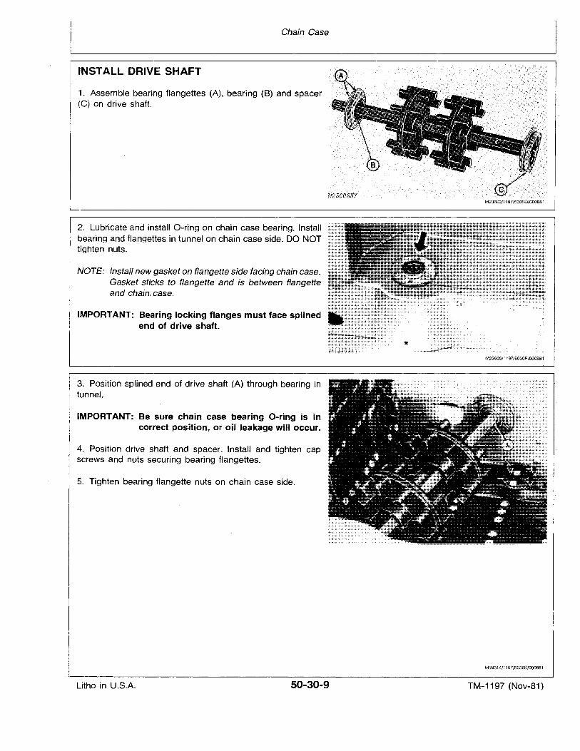
Chain Case
INSTALL DRIVE SHAFT
1. Assemble bearing flangettes (A), bearing (B) and spacer(C) on drive shaft.
2. Lubricate and install O-ring on chain case bearing. Installbearing and flangettes in tunnel on chain case side. DO NOTtighten nuts.
NOTE: Install new gasket on flangette side facing chain case.Gasket sticks to flangette and is between flangetteand chain, case.
IMPORTANT: Bearing locking flanges must face splinedend of drive shaft.
3. Position splined end of drive shaft (A) through bearing intunnel.
IMPORTANT: Be sure chain case bearing O-ring is incorrect position, or oil leakage will occur.
4. Position drive shaft and spacer. Install and tighten capscrews and nuts securing bearing flangettes.
5. Tighten bearing flangette nuts on chain case side.
M23602/1197/50300/OOO9B 1
M23603/1197/5030R/OOO9B1
M29314/1197/5030S/0009B1
Litho in U.S.A. 50-30-9 TM-1,197 (Nov-81)
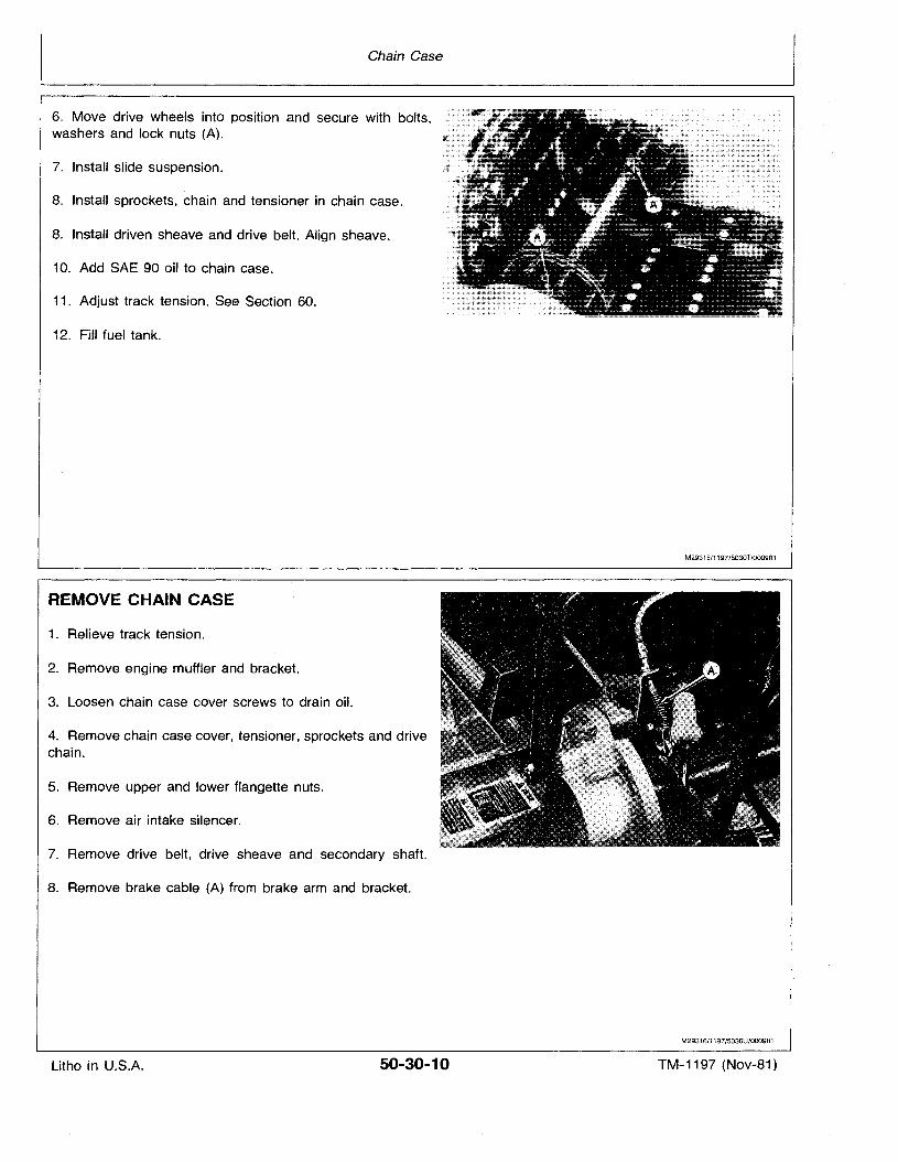
Chain Case
6. Move drive wheels into position and secure with bolts,washers and lock nuts (A).
7. Install slide suspension.
8. Install sprockets, chain and tensioner in chain case.
8. Install driven sheave and drive belt. Align sheave.
10. Add SAE 90 oil to chain case.
11. Adjust track tension. See Section 60.
12. Fill fuel tank.
M29315/1197/5030T/0OO9B1
REMOVE CHAIN CASE
1. Relieve track tension.
2. Remove engine muffler and bracket.
3. Loosen chain case cover screws to drain oil.
4. Remove chain case cover, tensioner, sprockets and drivechain.
5. Remove upper and lower flangette nuts.
6. Remove air intake silencer.
7. Remove drive belt, drive sheave and secondary shaft.
8. Remove brake cable (A) from brake arm and bracket.
M29316/1197/5030U/OOO9B1
Litho in U.S.A. 50-30-10 TM-1197 (Nov-81)
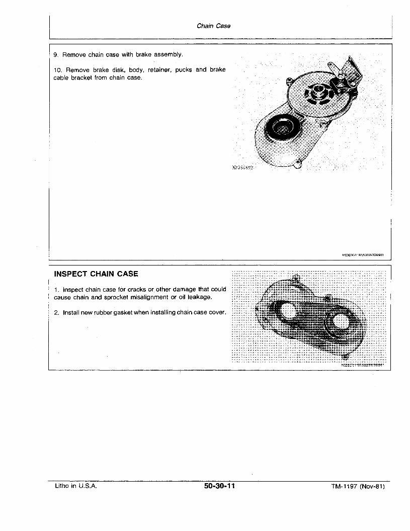
Chain Case
9. Remove chain case with brake assembly.
10. Remove brake disk, body, retainer, pucks and brakecable bracket from chain case.
INSPECT CHAIN CASE
1. Inspect chain case for cracks or other damage that couldcause chain and sprocket misalignment or oil leakage.
2. Install new rubber gasket when installing chain case cover.
M23606/1197/5030V/000981
Litho in U.S.A. 50-30-11 TM-1197 (Nov-81)
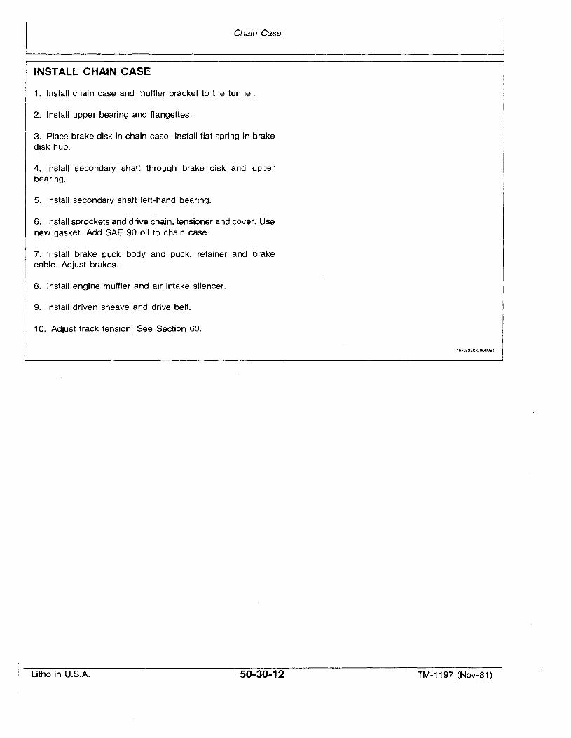
Chain Case
INSTALL CHAIN CASE
1. Install chain case and muffler bracket to the tunnel.
2. Install upper bearing and flangettes.
"3. Place brake disk in chain case. Install flat spring in brakedisk hub.
4. lnstall secondary shaft through brake disk and upperbearing.
5. Install secondary shaft left-hand bearing.
6. Install sprockets and drive chain, tensioner and cover. Usenew gasket. Add SAE 90 oil to chain case.
7. Install brake puck body and puck, retainer and brake.cable. Adjust brakes.
8. Install engine muffler and air intake silencer.
9. Install driven sheave and drive belt.
10. Adjust track tension. See Section 60.
1197/5030X/000981
Litho in U.S.A. 50-30-12 TM-1197 (Nov-81)
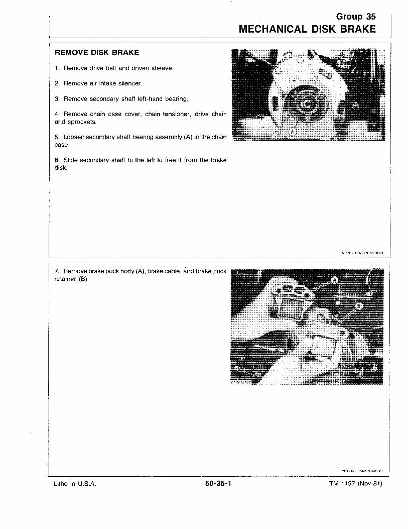
REMOVE DISK BRAKE
1. Remove drive belt and driven sheave.
2. Remove air intake silencer.
3. Remove secondary shaft left-hand bearing.
4. Remove chain case cover, chain tensioner, drive chainand sprockets.
5. Loosen secondary shaft bearing assembly (A) in the chaincase.
6. Slide secondary shaft to the left to free it from the brakedisk.
7. Remove brake puck body (A), brake cable, and brake puckretainer (B).
Group 35
MECHANICAL DISK BRAKE
M2931 7/1197/5035A/000981
M23609/1197/5035B/OOO9B1
Litho in U.S.A. 50-35-1 TM-1197 (Nov-81)
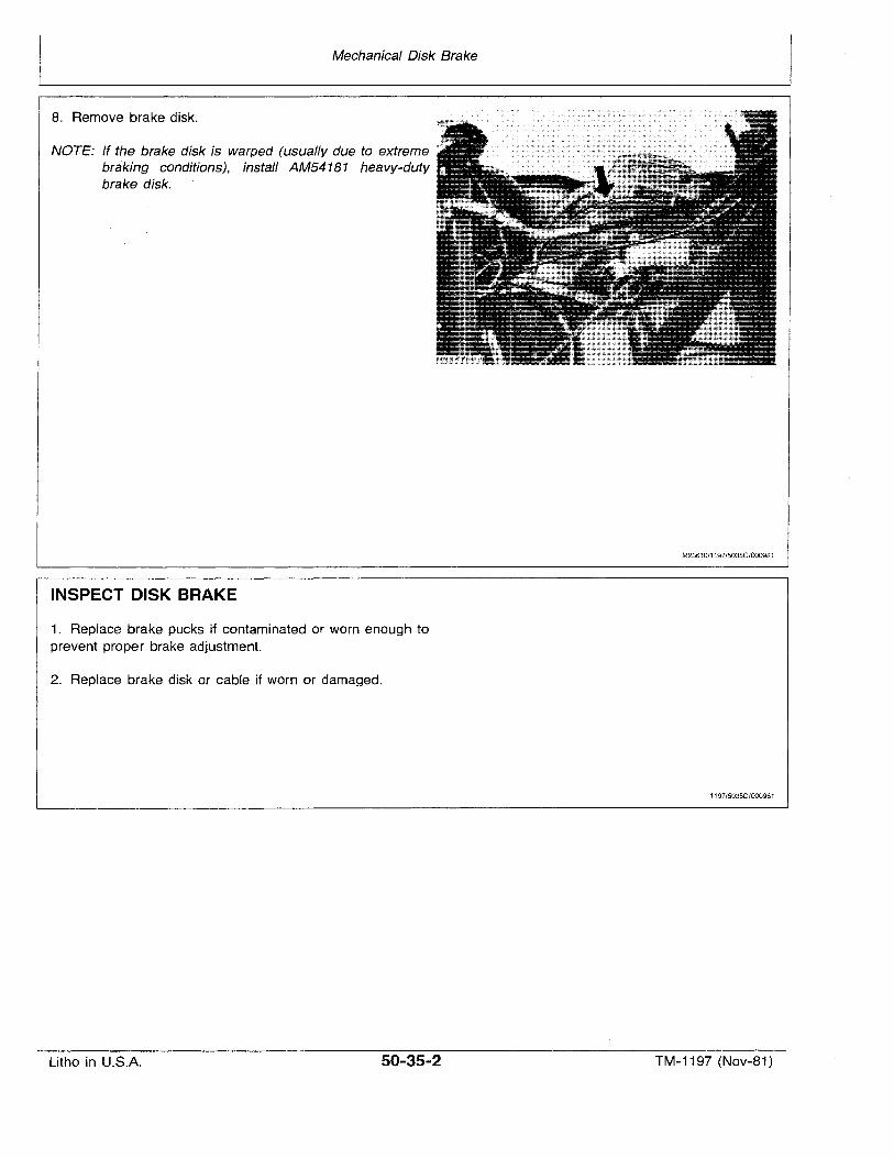
Mechanical Disk Brake
8. Remove brake disk.
NOTE: If the brake disk is warped (usually due to extremebraking conditions), install AM54181 heavy-dutybrake disk.
INSPECT DISK BRAKE
1. Replace brake pucks if contaminated or worn enough toprevent proper brake adjustment.
2. Replace brake disk or cable if worn or damaged.
M23610/1197/5035C/000981
1197/50350/000981
Litho in U.S.A. 50-35-2 TM-1197 (Nov-81)
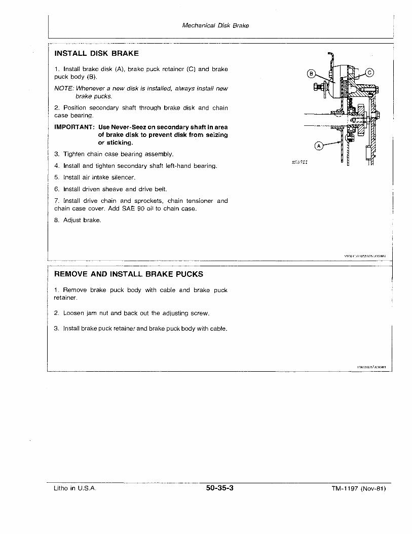
Mechanical Disk Brake
INSTALL DISK BRAKE
1. Install brake disk (A), brake puck retainer (C) and brakepuck body (8).
NOTE: Whenever a new disk is installed, always install newbrake pucks.
2. Position secondary shaft through brake disk and chaincase bearing.
IMPORTANT: Use Never-Seez on secondary shaft in areaof brake disk to prevent disk from seizingor sticking.
3. Tighten chain case bearing assembly.
4. Install and tighten secondary shaft left-hand bearing.
5. Install air intake silencer.
6. Install driven sheave and drive belt.
7. Install drive chain and sprockets, chain tensioner andchain case cover. Add SAE 90 oil to chain case.
8. Adjust brake.
REMOVE AND INSTALL BRAKE PUCKS
1. Remove brake puck body with cable and brake puckretainer.
2. Loosen jam nut and back out the adjusting screw.
3. Install brake puck retainer and brake puck body with cable.
M23611/1197/5035E/000981
1197/5035F/000981
Litho in U.S.A. 50-35-3 TM-1197 (Nov-81 )
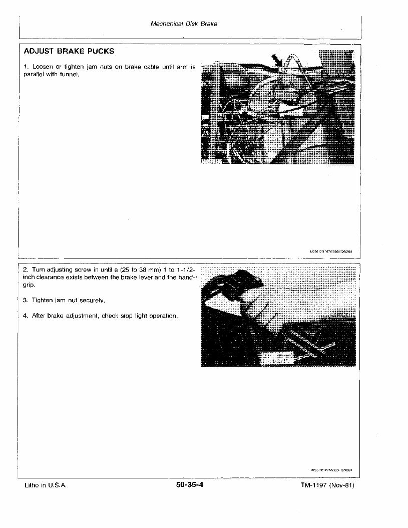
Mechanical Disk Brake
ADJUST BRAKE PUCKS
1. Loosen or tighten jam nuts on brake cable until arm isparallel with tunnel.
2. Turn adjusting screw in until a (25 to 38 mm) 1 to 1-1/2inch clearance exists between the brake lever and the hand-:grip.
3. Tighten jam nut securely.
4. After brake adjustment, check stop light operation.
M23612/1197/5035G/250981
M23613/1197/5035H/250981
Litho in U.S.A. 50-35-4 TM-1197 (Nov-81)
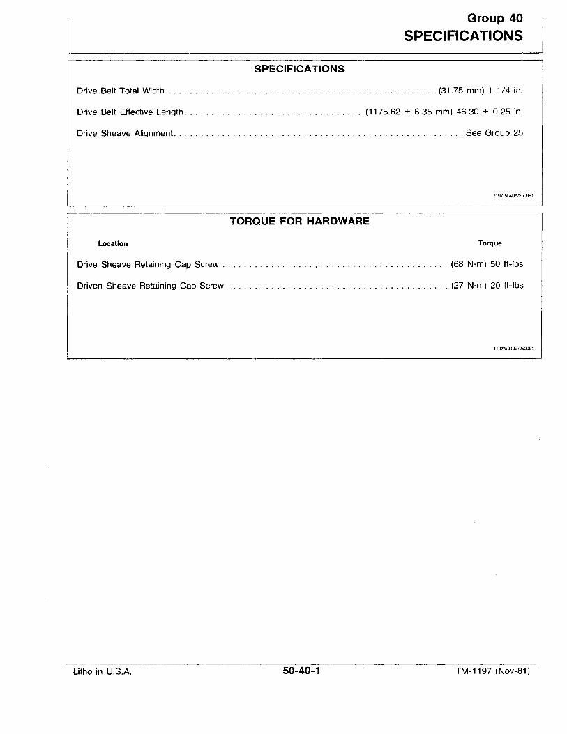
Group 40
SPECIFICATIONS
SPECIFICATIONS
Drive Belt Total Width (31.75 mm) 1-1/4 in.
Drive Belt Effective Length. . . . . . . . . . . . . . . . . . . . . . . . . . . . . . . . . (1175.62 ± 6.35 mm) 46.30 ± 0.25 in.
Drive Sheave Alignment See Group 25
1197/5040A/250981
TORQUE FOR HARDWARE
Location Torque
Drive Sheave Retaining Cap Screw (68 N·m) 50 ft-Ibs
Driven Sheave Retaining Cap Screw (27 N·m) 20 ft-Ibs
1197/50408/250981
Litho in U.S.A. 50-40-1 TM-1197 (Nov-81)

Litho in U.S.A.
Specifications
50-40-2 TM-1197 (Nov-B1)
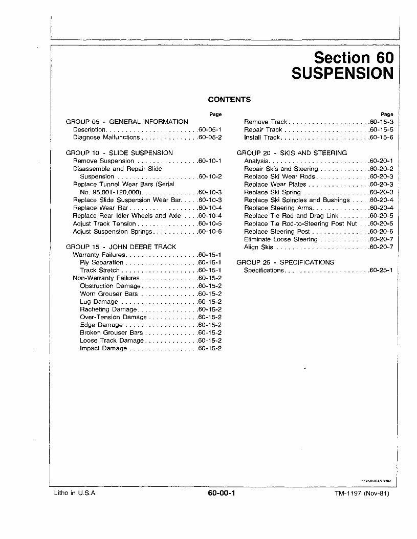
Section 60SUSPENSION
CONTENTS
Page
GROUP 05 - GENERAL INFORMATIONDescription. . . . . . . . . . . . . . . . . . . . . . . .60-05-1Diagnose Malfunctions 60-05-2
GROUP 10 - SLIDE SUSPENSIONRemove Suspension 60-10-1Disassemble and Repair Slide
Suspension 60-10-2Replace Tunnel Wear Bars (Serial
No. 95,001-120,000) 60-10-3Replace Slide Suspension Wear Bar.. ~ ..60-10-3Replace Wear Bar 60-10-4Replace Rear Idler Wheels and Axle 60-10-4Adjust Track Tension 60-10-5Adjust Suspension Springs 60-10-6
GROUP 15 - JOHN DEERE TRACKWarranty Failures 60-15-1
Ply Separation 60-15-1Track Stretch 60-15-1
Non-Warranty Failures 60-15-2Obstruction Damage 60-15-2Worn Grouser Bars 60-15-2Lug Damage 60-15-2Racheting Damage 60-15-2Over-Tension Damage 60-15-2Edge Damage 60-15-2Broken Grouser Bars 60-15-2Loose Track Damage 60-15-2Impact Damage 60-15-2
Page
Remove Track 60-15-3Repair Track 60-15-5Install Track 60-15-6
GROUP 20 - SKIS AND STEERINGAnalysis. . . . . . . . . . . . . . . . . . . . . . . . . .60-20-1Repair Skis and Steering 60-20-2Replace Ski Wear Rods 60-20-3Replace Wear Plates 60-20-3Replace Ski Spring 60-20-3Replace Ski Spindles and Bushings 60-20-4Replace Steering Arms 60-20-4Replace Tie Rod and Drag Link 60-20-5Replace Tie Rod-to-Steering Post Nut 60-20-5Replace Steering Post 60-20-6Eliminate Loose Steering 60-20-7Align Skis 60-20-7
GROUP 25 - SPECIFICATIONSSpecifications 60-25-1
1197/6005A/250981
Litho in U.S.A. 60-00-1 TM-1197 (Nov-81)

Litho in U.S.A.
Suspension
60-00-2 TM-1197 (Nov-B1)
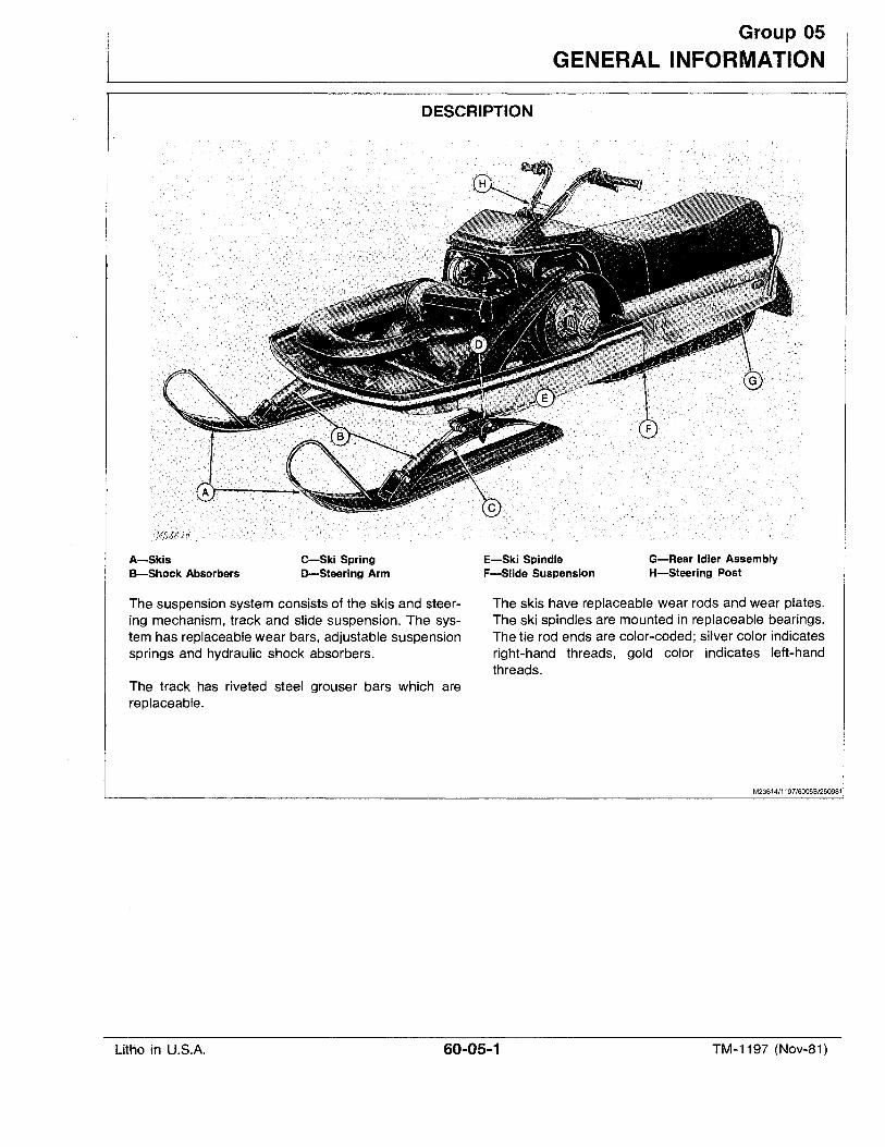
Group 05
GENERAL INFO'RMATION
DESCRIPTION
A-SkisB-Shock Absorbers
C-Ski SpringD-Steering Arm
E-Ski SpindleF-Slide Suspension
G-Rear Idler AssemblyH-Steering Post
The suspension system consists of the skis and steering mechanism, track and slide suspension. The system has replaceable wear bars, adjustable suspensionsprings and hydraulic shock absorbers.
The track has riveted steel grouser bars which arereplaceable.
The skis have replaceable wear rods and wear plates.The ski spindles are mounted in replaceable bearings.The tie rod ends are color-coded; silver color indicatesright-hand threads, gold color indicates left-handthreads.
M23614/1197/6005B/250981
Litho in U.S.A. 60-05-1 TM-1197 (Nov-81)
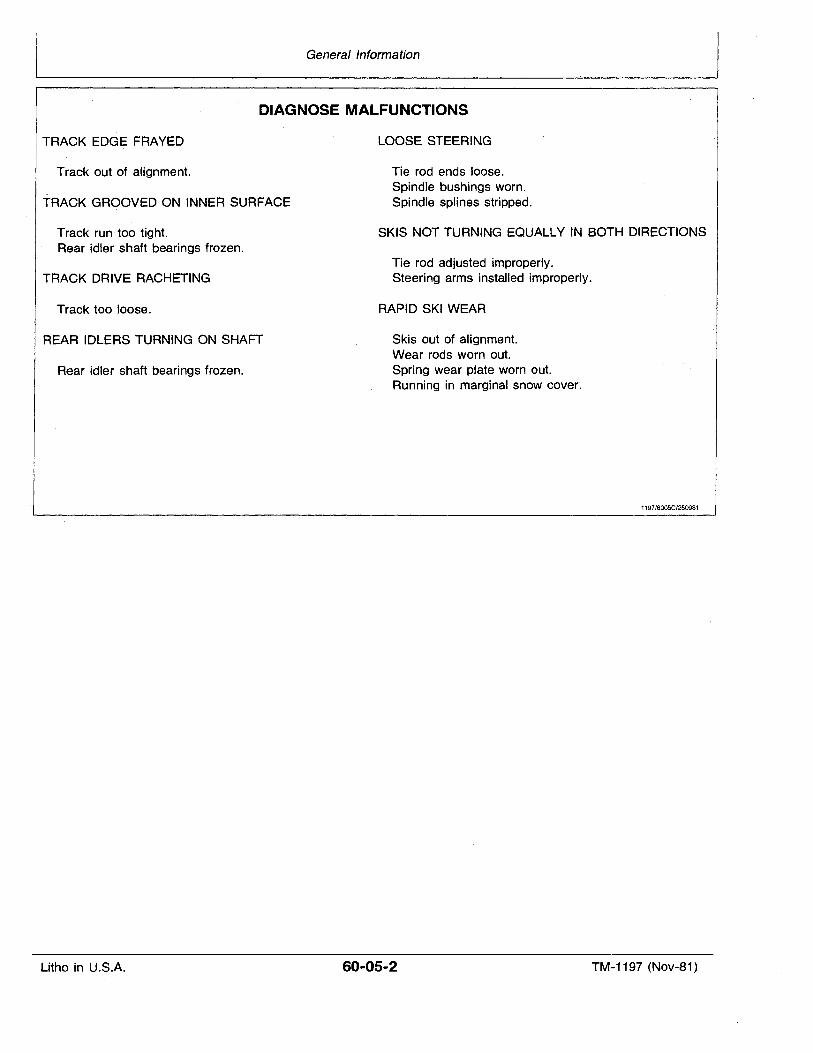
General Information
DIAGNOSE MALFUNCTIONS
TRACK EDGE FRAYED
Track out of alignment.
TRACK GROOVED ON INNER SURFACE
Track run too tight.Rear idler shaft bearings frozen.
TRACK DRIVE RACHETING
Track too loose.
REAR IDLERS TURNING ON SHAFT
Rear idler shaft bearings frozen.
LOOSE STEERING
Tie rod ends loose.Spindle bushings worn.Spindle splines stripped.
SKIS NOT TURNING EaUALLY IN BOTH DIRECTIONS
Tie rod adjusted improperly.Steering arms installed improperly.
RAPID SKI WEAR
Skis out of alignment.Wear rods worn out.Spring wear plate worn out.Running in marginal snow cover:
1197/6005C/250981
Litho in U.S.A. 60-05-2 TM-1197 (Nov-81)
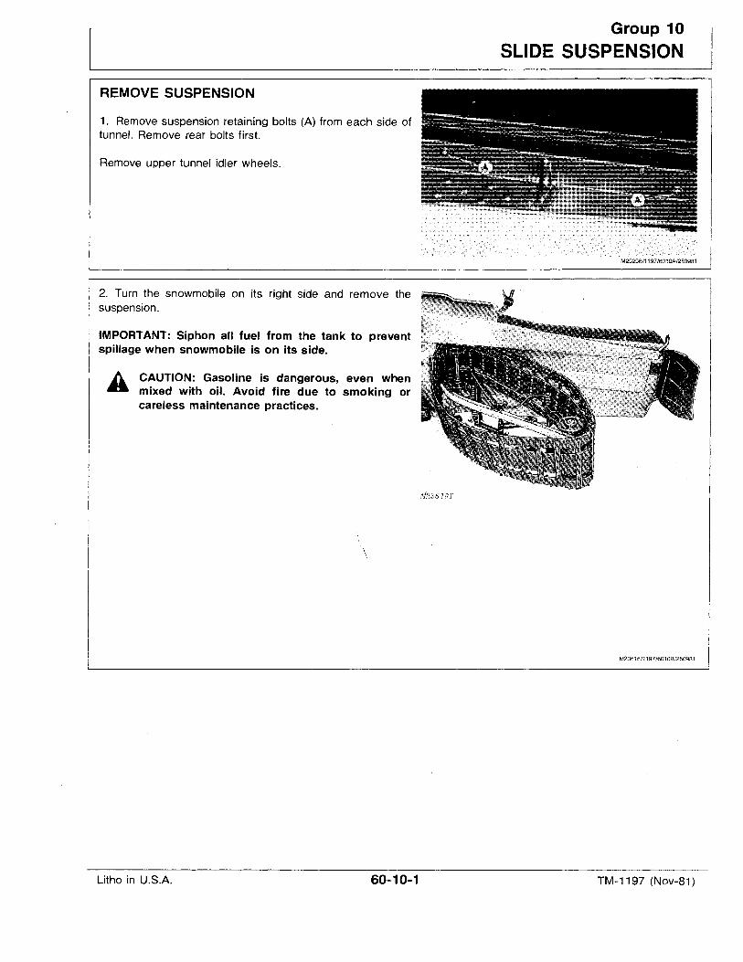
REMOVE SUSPENSION
1. Remove suspension retaining bolts (A) from each side oftunnel. Remove rear bolts first.
Remove upper tunnel idler wheels.
2. Turn the snowmobile on its right side and remove thesuspension.
IMPORTANT: Siphon all fuel from the tank to preventspillage when snowmobile is on its side.
CAUTION: Gasoline is dangerous, even whenmixed with oil. Avoid fire due to smoking orcareless maintenance practices.
\
Group 10
SLIDE SUSPENSION
M29296/1197/6010A/250981
M23616/1197/6010B/250981
Litho in U.S.A. 60-10-1 TM-1197 (Nov-81)
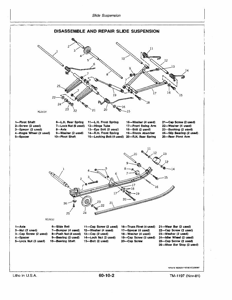
Slide Suspension
DISASSEMBLE AND REPAIR SLIDE SUSPENSION
M2361.9
1-Pivot Shaft2-Screw (2 used)3-Spacer (2 used)4-Bogie Wheel (2 used)5-Spacer
6-L.H. Rear Spring 11-L.H. Front Spring 16-Washer-(4 used)7-Lock Nut (6 used) 12-Hinge Tube 17-Front Swing Arm8-Axle 13-Eye Bolt (2 used) 18-Bolt (2 used)9-Washer (2 used) 14-R.H. Front Spring 19-5hock Absorber
1o-Pivot Shaft 15-Locking Bolt (4 used) 20-R.H. Rear Spring
1314
/"'~~ ','" ~, I
@ '~I~
16 '"15
21-Cap Screw (2 used)22--Washer (4 used)23-Bushing (2 used)24-Slip Bearing (2 used)25-Rear Pivot Arm
1,<,
I
26---~i
/25
M23620
11
:<0 ~ /12 13,,/' @,~/
/ 129 ~ /~ '@
8-rJl" e>--14"-
7- Q
1-Axle2-Nut (2 used)3-Cap Screw (2 used)4-Spacer5-Lock Nut (3 used)
6-Slide Rail 11-Cap Screw -(2 used) 16-Truss Rivet (4 used) 21-Wear Bar (2 used)7-Bumper (4 used) 12-Washer (4 used) 17-Spacer (4 used) 22-Cap Screw (2 used)8-Push Nut (4 used) 13-Cap (2 used) 18-Washer (4 used) 23-Washer (2 used)9-Bearing (2 used) 14-Lock Nut (2 used) 19-Cap Screw (2 used) 24-ldler Wheel (2 used)
1o-Searing Shaft 15-Solt (2 used) 2o-Cap Screw 25-Cap Screw (2 used)26-Wear Bar Stop (2 ,used)
M23619 M23620/1197/601OC/290981
Litho in U.S.A. 60-10-2 TM-1197 (Nov-81)
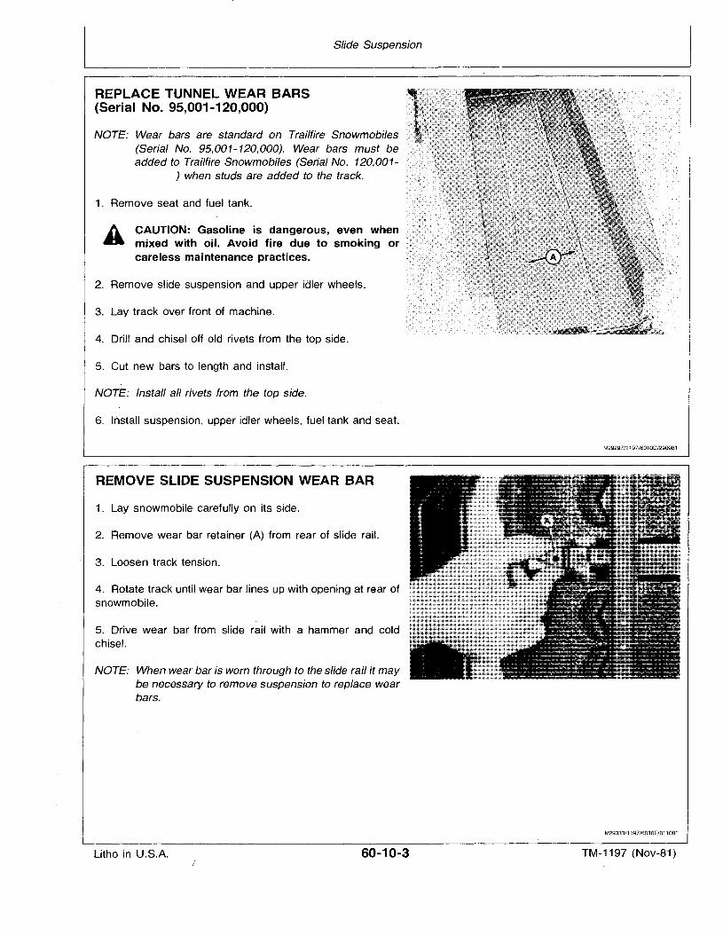
Slide Suspension
REPLACE TUNNEL WEAR BARS(Serial No. 95,001-120,000)
NOTE: Wear bars are standard on Trailfire Snowmobiles(Serial No. 95,001-120,000). Wear bars must beadded to Trailfire Snowmobiles (Serial No. 120,001
) when studs are added to the track.
1. Remove seat and fuel tank.
CAUTION: Gasoline is dangerous, even whenmixed 'with oil. Avoid fire due to smoking orcareless maintenance practices.
2. Remove slide suspension and upper idler wheels.
3. Lay track over front of machine.
4. Drill and chisel off old rivets from the top side.
5. Cut new bars to length and install.
NOTE: Install all rivets from the top side.
6. Install suspension, upper idler wheels, fuel tank and seat.
REMOVE SLIDE SUSPENSION WEAR BAR
1. Lay snowmobile carefully on its side.
2. Remove wear bar retainer (A) from rear of slide rail.
3. Loosen track tension.
4. Rotate track until wear bar lines up with opening at rear ofsnowmobile.
5. Drive wear bar from slide rail with a hammer and coldchisel.
NOTE: When wear bar is worn through to the slide rail it maybe necessary to remove suspension to replace wearbars.
M29297/1197/6010D/290981
M29333/1197/6010E/011081
Litho in U.S.A. 60-10-3 TM-1197 (Nov-81)
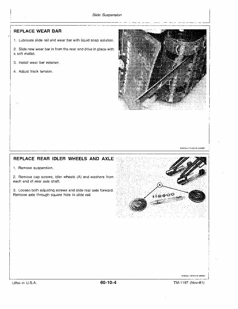
Slide Suspension
REPLACE WEAR BAR
1. Lubricate slide rail and wear bar with liquid soap solution.
2. Slide new wear bar in from the rear and drive in place witha soft mallet.
3. Install wear bar retainer.
4. Adjust track tension.
REPLACE REAR IDLER WHEELS AND AXLE
1. Remove suspension.
2. Remove cap screws, idler wheels (A) and washers fromeach end of rear axle shaft.
3. Loosen both adjusting screws and slide rear axle forward.Remove axle through square hole in slide rail.
M29334/1197/6010E1/290981
M29298/1197/6010F/290981
Litho in U.S.A. 60-10-4 TM-1197 (Nov-a1)
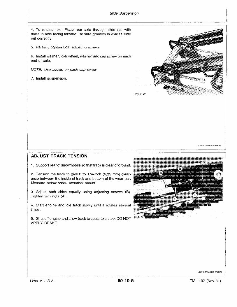
Slide Suspension
4. To reassemble: Place rear axle through slide rail withholes in axle facing forward. Be sure grooves in axle fit sliderail correctly.
5. Partially tighten both adjusting screws.
6. Install washer, idler wheel, washer and cap screw on eachend of axle.
NOTE: Use Loctite on each cap screw.
7. Install suspension.
ADJUST TRACK TENSION
1. Support rear of snowmobile so that track is clear of ground.
2. Tension the track to give 0 to 1/4-inch (6.35 mm) clearance between the inside of track and bottom of the wear bar.Measure below shock absorber mount.
3. Adjust both sides equally using adjusting screws (B).Tighten jam nuts (A).
4. Start engine and idle track slowly until it rotates. severaltimes.
5. Shut off engine and allow track to coast to a stop. DO NOTAPPLY BRAKE.
M23624/1197/6010G/290981
M23319/1197/6010H/290981
Litho in U.S.A. 60-10-5 TM-1197 (Nov-81)
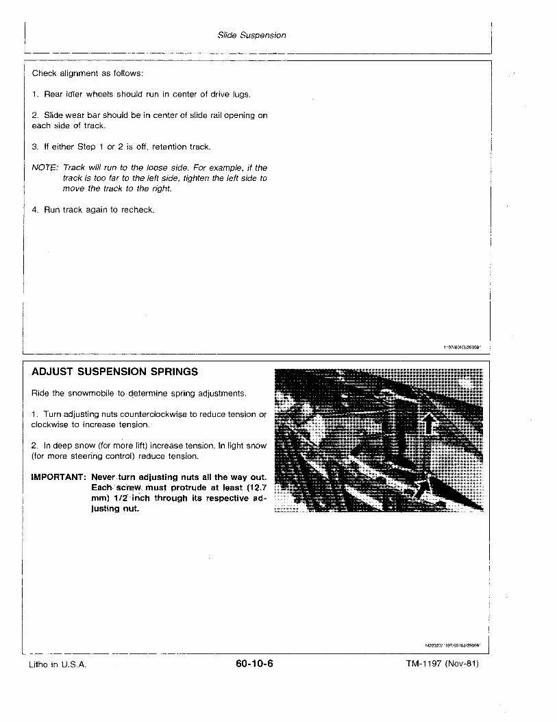
Slide Suspension
Check alignment as follows:
1. Rear idler wheels should run in center of drive lugs.
2. Slide wear bar should be in center of slide rail opening oneach side of track.
3. If either Step 1 or 2 is off, retention track.
NOTE: Track will run to the loose side. For example, if thetrack is too far to the left .side, tighten the left side tomove the track to the right.
4. Run track again to recheck.
1197/60101/290981
ADJUST SUSPENSION SPRINGS
Ride the snowmobile todeterrnlne spring adjustments.
1. Turn adjusting nuts counterclockwise to reduce tension orclockwise to increase tension.
2. In deep snow (for more lift) increase tension. In light snow(for more steering control) reduce tension.
IMPORTANT: Never,:turn adjusting nuts all the way out.Each,'s'c'r~w~must protrude at least (12.7mm) 1/2" Inch through its respective adjustingnut.
M23320/1197/601OJ/290981
Litho in U.S.A. 60-10-6 TM-1197 (Nov-81)
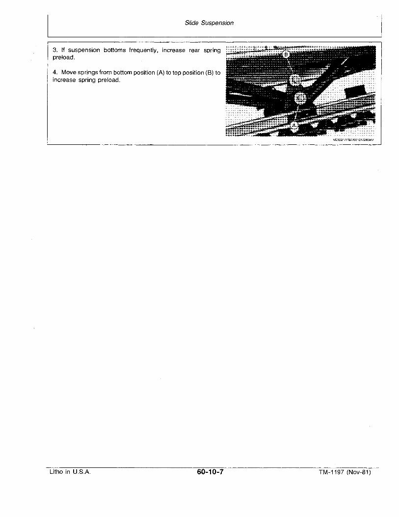
Slide Suspension
3. If suspension bottoms frequently, increase rear springpreload.
4. Move springs from bottom position (A) to top position (8) toincrease spring preload.
M23321/1197/6010K/280981
Litho in U.S.A. 60-10-7 TM-1197 (Nov-81)

Litho in U.S.A.
Slide Suspension
60-10-8 TM-1197 (Nov-81)
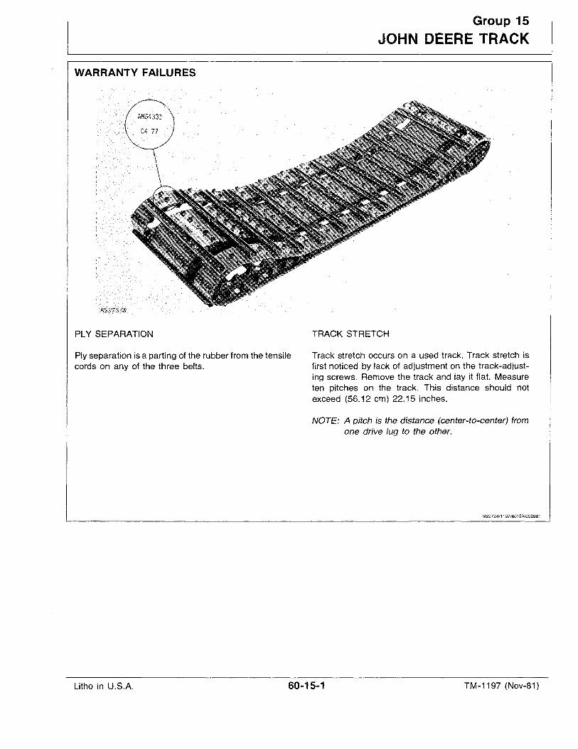
WARRANTY FAILURES
Group 15
JOHN DEERE TRACK
PLY SEPARATION
Ply separation is a parting of the rubber from the tensilecords on any of the three belts.
TRACK STRETCH
Track stretch occurs on a used track. Track stretch isfirst noticed by lack of adjustment on the track-adjusting screws. Remove the track and lay it flat. Measureten pitches on the track. This distance should notexceed (56.12 cm) 22.15 inches.
NOTE: A pitch is the distance (center-to-center) fromone drive lug to the other.
M22724/1197/6015A/290981
Litho in U.S.A. 60-15-1 TM-1197 (Nov-8'1)
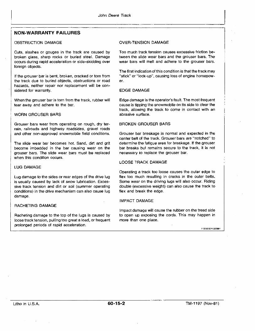
John Deere Track
NON-WARRANTY FAILURES
OBSTRUCTION DAMAGE
Cuts, slashes or gouges in the track are caused bybroken glass, sharp rocks or buried steel. Damageoccurs during rapid acceleration or side-skidding overforeign objects.
If the grouser bar is bent, broken, cracked or torn fromthe track due to buried objects, obstructions or roadhazards, neither repair nor replacement will be considered for warranty.
When the grouser bar is torn from the track, rubber willtear away and adhere to the bar.
WORN GROUSER BARS
Grouser bars wear from operating on rough, dry terrain, railroads and highway roadsides, gravel roadsand other non-approved snowmobile field conditions.
The slide wear bar becomes hot. Sand, dirt and gritbecome imbedded in the bar causing wear on thegrouser bars. The slide wear bars must be replacedwhen this condition occurs.
LUG DAMAGE
Lug damage to the sides or rear edges of the drive lugis usually caused by lack of snow lubrication. Excessive track tension and dirt. or soil (summer operatingconditions) in the drive mechanism can also cause lugdamage.
RACHETING DAMAGE
Racheting damage to the top of the lugs is caused byloose track tension, pulling too great a load, or frequentprolonged periods of rapid acceleration.
QVER-TENSION DAMAGE
Too much track tension causes excessive friction between the slide wear bars and the grouser bars. Thewear bars will melt and adhere to the grouser bars.
The first indication of this condition is that the track may."stick" or "lock-up", causing loss of engine horsepower.
EDGE DAMAGE
Edge damage is the operator's fault. The most frequentcause is tipping the snowmobile on its side to clear thetrack, allowing the track to come in contact with anabrasive surface.
BROKEN GROUSER BARS
Grouser bar breakage is normal and expected in thecenter belt of the track. Grouser bars are "notched" todetermine the fatigue area for breakage. If the grouserbar breaks but remains secure to the track, it is notnecessary to replace the grouser bar.
LOOSE TRACK DAMAGE
Operating a track too loose causes the outer edge toflex too much resulting in cracks in the outer belts.Some wear on the driving lugs will also occur. Ridingdouble (excessive weight) can also cause the track toflex and break the edge.
IMPACT DAMAGE
Impact damage will cause the rubber on the tread sideto open up exposing the cords. This may happen inmore than one place.
1197/6015A1/250981
Litho in U.S.A. 60-15-2 TM-1197 (Nov~81)
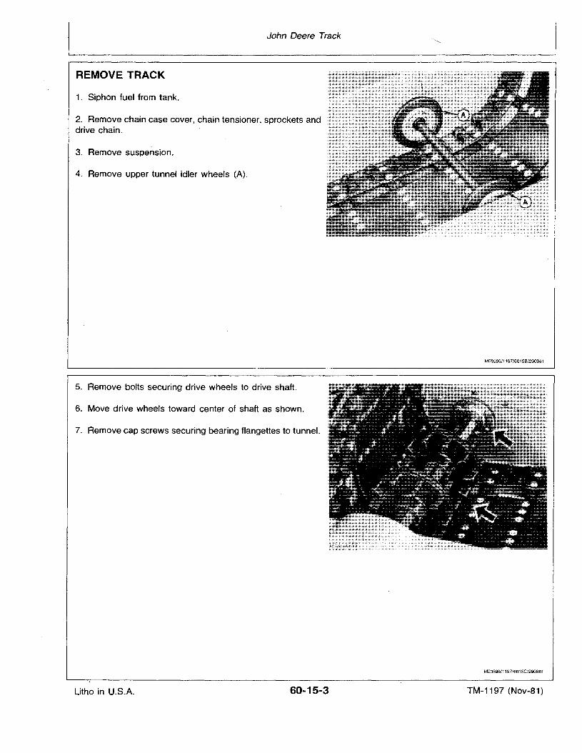
John Deere Track
REMOVE TRACK
1. Siphon fuel from tank.
2. Remove chain case cover, chain tensioner, sprockets anddrive chain.
3. Remove suspension.
4. Remove upper tunnel idler wheels (A).
5. Remove bolts securing drive wheels to drive shaft.
6. Move drive wheels toward center of shaft as shown.
7. Remove cap screws securing bearing flangettes to tunnel.
M29299/1197/6015B/290981
M23599/1197/6015C/290981
Litho in U.S.A. 60-15-3 TM-1197 (Nov-81)
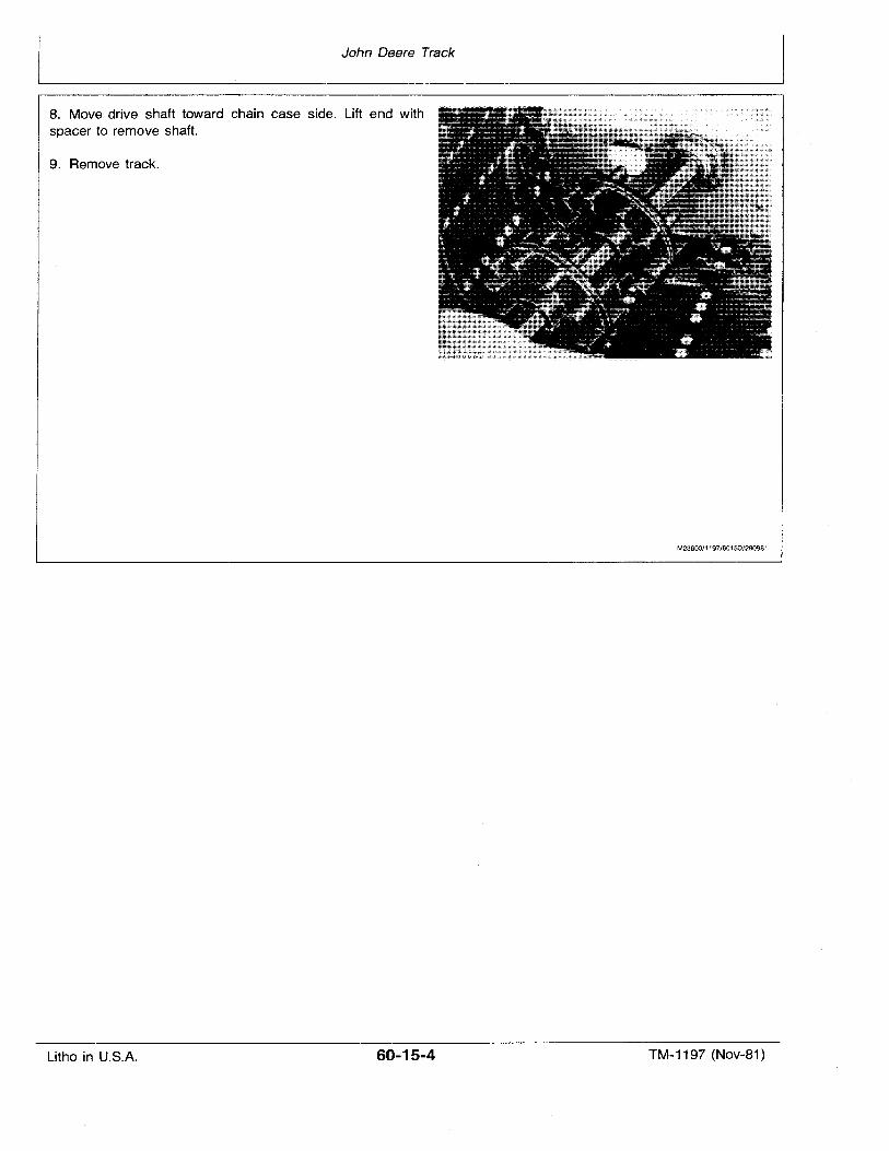
John Deere Track
8. Move drive shaft toward chain case side. Lift end withspacer to remove shaft.
9. Remove track.
M23600/1197/60150/290981
Litho in U.S.A. 60-15-4 TM-1197 (Nov-81)
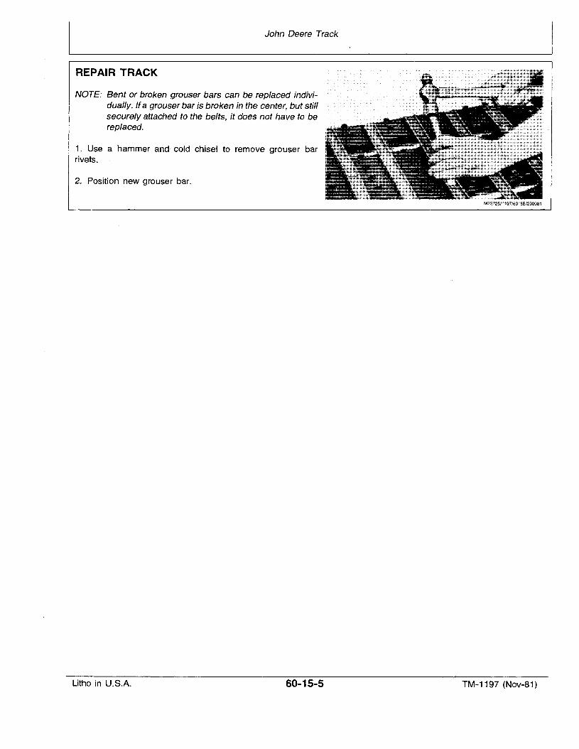
John Deere Track
REPAIR TRACK
NOTE: Bent or broken grouser bars can be replaced individually."Jfa grouser bar is broken in the center, but stillsecurely attached to the belts, it does not have to bereoleced.
1. Use a hammer and" cold chisel to remove grouser barrivets.
2. Position new grouser bar.
M22725/1197/6015E/290981
Litho in U.S.A. 60-15-5 TM-1197 (Nov-81)
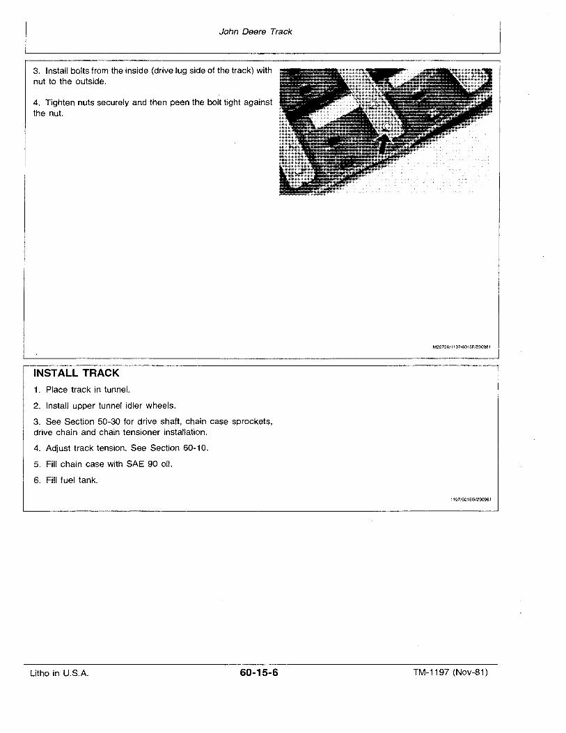
John Deere Track
3. Install bolts from the inside (drive lug side of the track) withnut to the outside.
4. Tighten nuts securely and then peen the bolt tight againstthe nut.
INSTALL TRACK
1. Place track in tunnel.
2. Install upper tunnel idler wheels.
3. See Section 50-30 for drive shaft, chain case sprockets,drive chain and chain tensioner installation.
4. Adjust track tension. See Section 60-10.
5. Fill chain case with SAE 90 oil.
6. Fill fuel tank.
M22726/1197/6015F1290981
1197/6015G/290981
Litho in U.S.A. 60-15-6 TM-1197 (Nov-81)
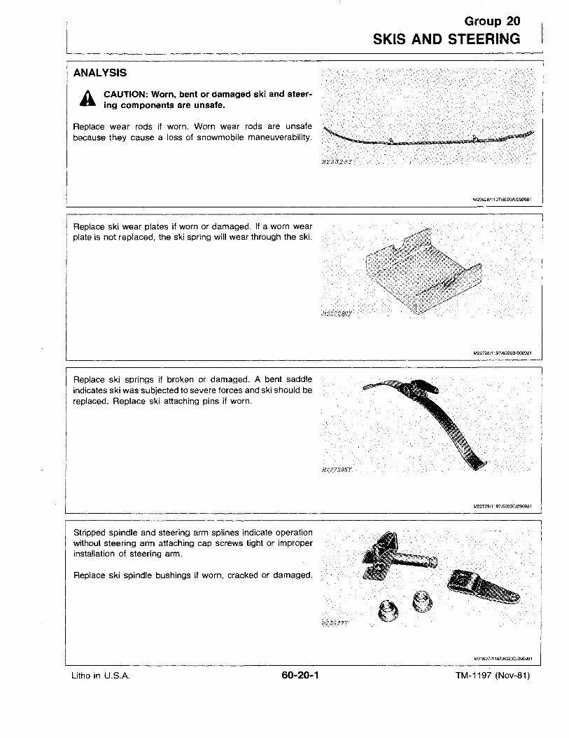
ANALYSIS
A CAUTION: Worn, bent or damaged ski and steering components are unsafe.
Replace wear rods if worn. Worn wear rods are unsafebecause they cause a loss of snowmobile maneuverability.
Replace ski wear plates if worn or damaged. If a worn wearplate is not replaced, the ski spring will wear through the ski.
Replace ski springs if broken or damaged. A bent saddleindicates ski was subjected to severe forces and ski should bereplaced. Replace ski attaching pins if worn.
Stripped spindle and steering arm splines indicate operationwithout steering arm attaching cap screws tight or improperinstallation of steering arm.
Replace ski spindle bushings if worn, cracked or damaged.
Group 20
SKIS AND STEERING
M23626/1197/6020AJ290981
M22728/1197/6020B/000981
M22729/1197/602OC/290981
M2362711197/6020D/290981
Litho in U.S.A. 60-20-1 TM-1197 (Nov-81)
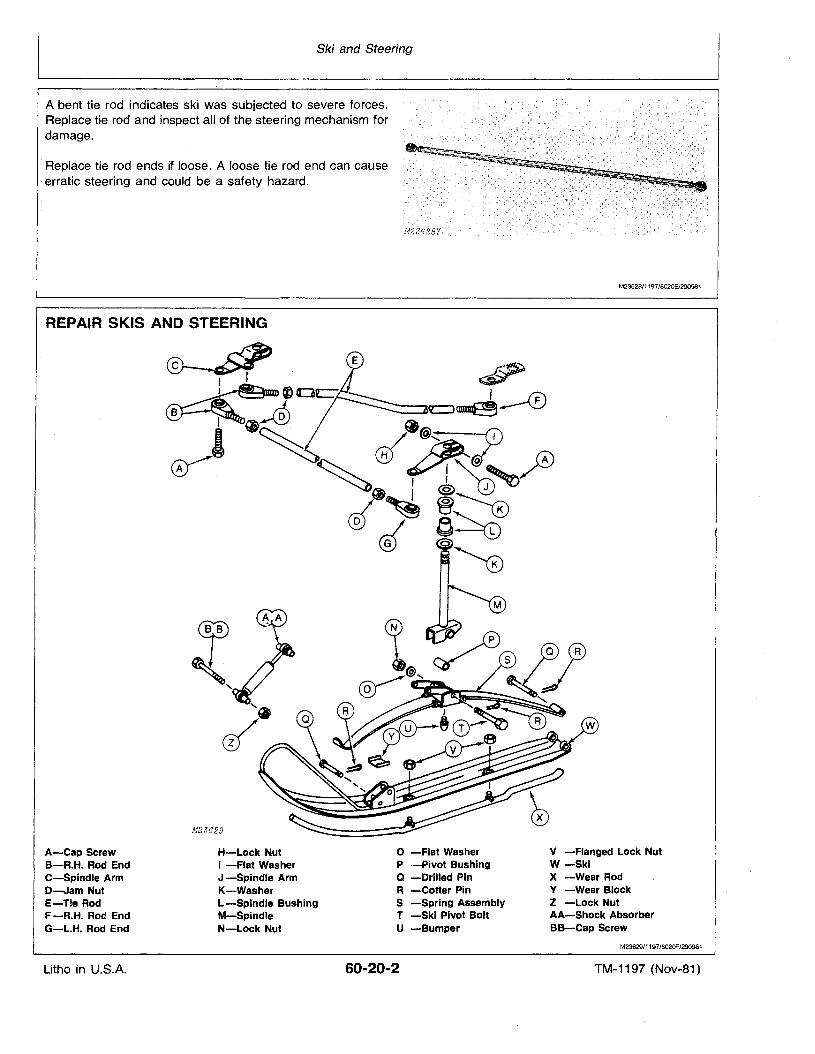
Ski and Steering
A bent tie rod indicates ski was subjected to severe forces.Replace tie rod and inspect all of the steering mechanism fordamage.
-Replace tie rod ends if loose. A loose tie rod end can cause.erratic steering and could be a safety hazard.
REPAIR SKIS AND STEERING
~I I1............,~....II111rm
M23629
..' . .................... ....... ............... ...
•••••
.... d···....
.... . ..
........... ..... ..
.....
........
.....
........
c-:..
~-·M~ 5( 8Y .:··.
M23628/1197/6020E/29Q981
A-Cap ScrewB-R.H. Rod EndC-Spindle ArmD-Jam NutE-Tie RodF -R.H. Rod EndG-L.H. Rod End
Litho in U.S.A.
H-Lock NutI -Flat WasherJ -Spindle ArmK-WasherL -Spindle BushingM-SpindleN-Lock Nut
o -Flat WasherP -Pivot BushingQ -Drilled PinR -Cotter PinS -Spring AssemblyT -Ski Pivot BoltU -Bumper
60-20-2
V -Flanged Lock NutW-SkiX -Wear RodV -Wear BlockZ -Lock NutAA-Shock AbsorberBB-Cap Screw
M23629/1197/602OF/290981
TM-1197 (Nov-81)
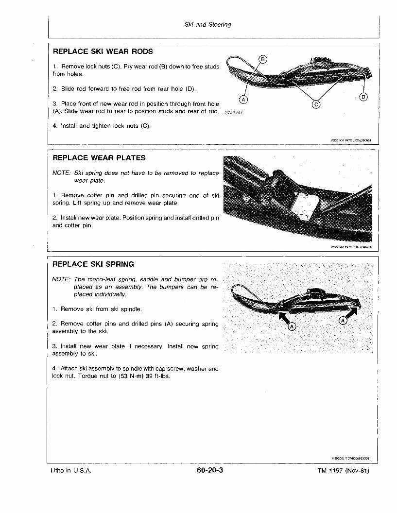
Ski and Steering
REPLACE SKI WEAR RODS
1. Remove lock nuts (C). Pry wear rod (8) down to free studsfrom holes.
2. Slide rod forward to free rod from rear hole (D).
3. Place front of new wear rod in position through front hole(A). Slide wear rod to rear to position studs and rear of rod. M23CJOI
4. Install and tighten lock nuts (C).
M23630/1197/6020G/290981
REPLACE WEAR PLATES
NOTE: Ski spring does not have to be removed to rep/acewear plate.
1. Remove cotter pin and drilled pin securing end of skispring. Lift spring up and remove wear plate.
2. Install new wear plate. Position spring and install drilled pinand cotter pin.
REPLACE SKI SPRING
NOTE: The mono-leaf spring, saddle and bumper are rep/aced as an assembly. The bumpers can be replaced individually.
1. Remove ski from ski spindle.
2. Remove cotter pins and drilled pins (A) securing springassembly to the ski.
3. Install new wear plate if necessary. Install new springassembly to ski.
4. Attach ski assembly to spindle with cap screw, washer andlock nut. Torque nut to (53 N·m) 39 ft-Ibs.
M22734/1197/6020H/290981
M29300/1197/60201/290981
Litho in U.S.A. 60-20-3 TM-1197 (Nov-81)
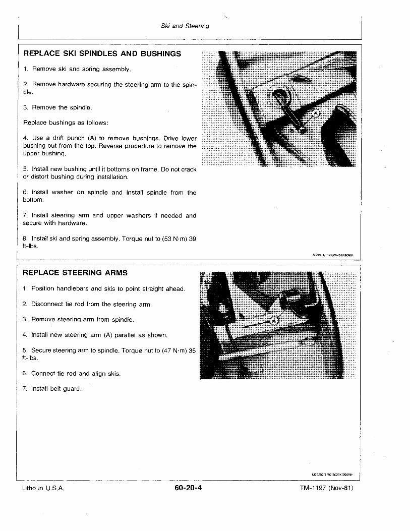
Ski and Steering
REPLACE SKI SPINDLES AND BUSHINGS
1. Remove ski and spring assembly.
2. Remove hardware securing the steering arm to the spindle.
3. Remove the spindle.
Replace bushings as follows:
4. Use a drift punch (A) to remove bushings. Drive lowerbushing out from the top. Reverse procedure to remove theupper bushing.
5. Install new bushing until it bottoms on frame. Do not crackor distort bushing during installation.
6. Install washer on spindle and install spindle from thebottom.
7. Install steering arm and upper washers if needed andsecure with hardware.
8. Install ski and spring assembly. Torque nut to (53 N·m) 39ft-Ibs.
REPLACE STEERING ARMS
1. Position handlebars and skis to point straight ahead.
2. Disconnect tie rod from the steering arm.
3. Remove steering arm from spindle.
4. Install new steering arm (A) parallel as shown.
5. Secure steering arm to spindle. Torque nut to (47 N'm) 35ft-Ibs.
6. Connect tie rod and align skis.
7. Install belt guard.
M29301/1197/602OJ/290981
M29302/1197/6020K/290981
Litho in U.S.A. 60-20-4 TM-1197 (Nov-81)
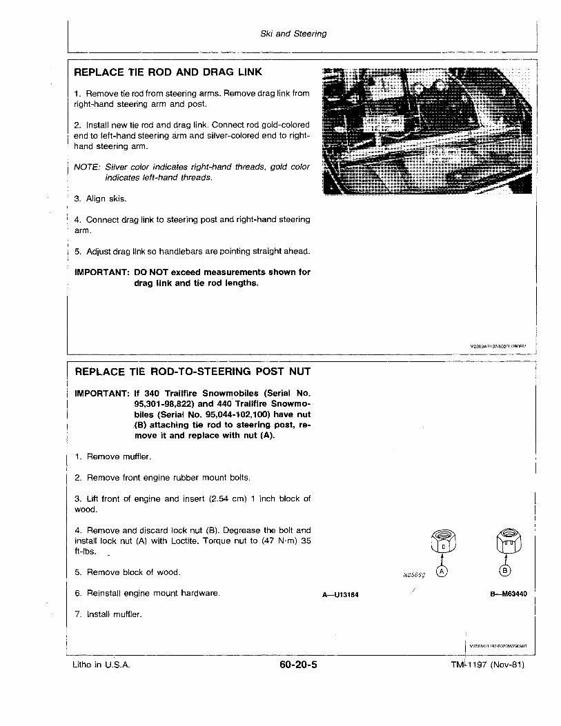
Ski and Steering
REPLACE TIE ROD AND DRAG LINK
1. Remove tie rod from steering arms. Remove drag link fromright-hand steering arm and post.
2. Install new tie rod and drag link. Connect rod gold-coloredend to left-hand steering arm and silver-colored end to righthand steering arm.
NOTE: Silver color indicates. right-hand threads, gold colorindicates left-hand threads.
3. Align skis.
4. Connect drag link to steering post and right-hand steeringarm.
5. Adjust drag link so handlebars are pointing straight ahead.
IMPORTANT: DO NOT exceed measurements shown fordrag link and tie rod lengths.
REPLACE TIE ROD-TO-STEERING POST NUT
IMPORTANT: If 340 Trailfire Snowmobiles (Serial No.95,301-98,822) and 440' Trailfire Snowmobiles (Serial No. 95,044-102,100) have nut.(B) attaching tie rod to steering post, remove it and replace with· nut (A).
1. Remove muffler.
2. Remove front engine rubber mount bolts.
3. Lift front of engine and insert (2.54 em) 1 inch block ofwood.
M23634/1197/6020l/290981
4. Remove and discard lock nut (8). Degrease the bolt andinstall lock nut (A) with Loetite. Torque nut to (47 N·m) 35ft-lbs.
5. Remove block of wood.
6. Reinstall engine mount hardware.
7. Install muffler.
A-U13184
M25669
/ B-M63440
M25660/1197/6020M/290981
Litho in U.S.A. 60-20-5 TM, 1197 (Nov-81)
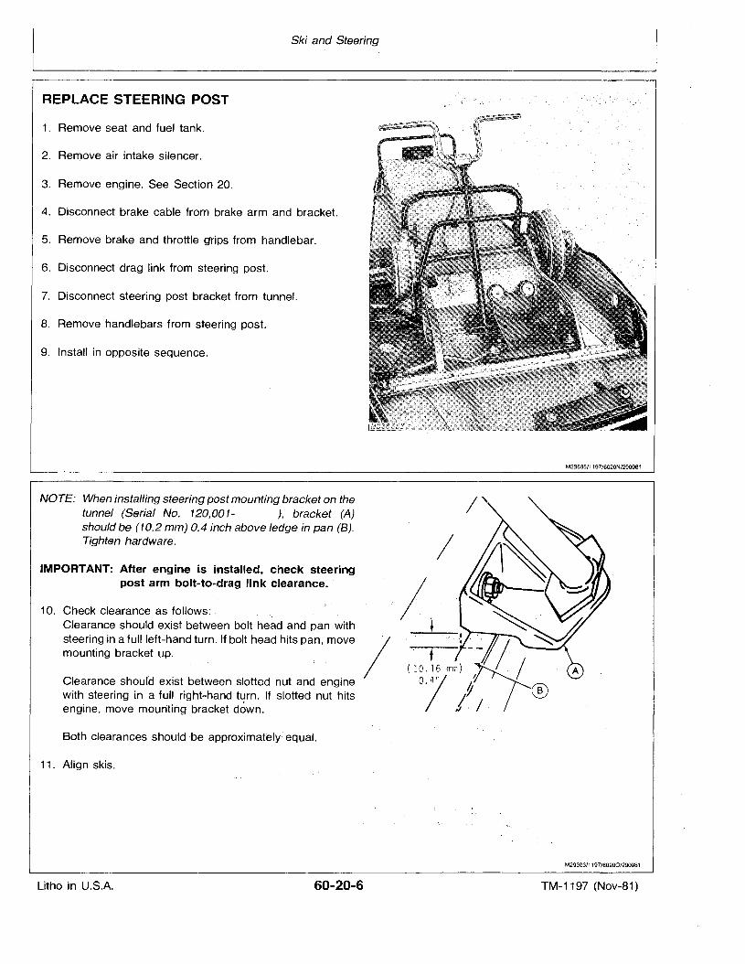
Ski and Steering
REPLACE STEERING POST
1. Remove seat and fuel tank.
2. Remove air intake silencer.
3. Remove engine. See Section 20.
4. Disconnect brake cable from brake arm and bracket.
5. Remove brake and throttle grips from handlebar.
6. Disconnect drag link from steering post.
7. Disconnect steering post bracket from tunnel.
8. Remove handlebars from steerinq post.
9. Install in opposite sequence.
NOTE: When installing steering post mounting bracket on thetunnel (Serial No. 120,001- ), bracket (A)should be (10.2 mm) 0.4 inch above ledge in pan (B).Tighten hardware.
IMPORTANT: After engine is installed, check steeringpost arm bolt-ta-drag link clearance.
10. Check clearance as follows: ,.Clearance should exist between bolt head and pan withsteering in a full left-hand turn. If bolt head hits pan, movemounting bracket up.
Clearance should exist between slotted nut and enginewith steering in a full right-hand turn, If slotted nut hitsengine, move mounting bracket down.
Both clearances should ,be aoproximatelvequal.
11. Align skis.
M23635/1197/6020N/290981
I
M29303/1197/602oo/290981
Litho in U.S.A. 60-20-6 TM-1197 (Nov-81)
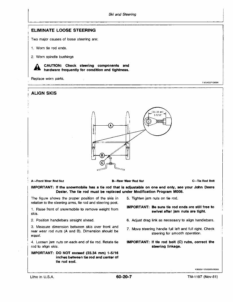
Ski and Steering
ELIMINATE LOOSE STEERING
Two major causes of loose steering are:
1. Worn tie rod ends.
2. Worn spindle bushings
A CAUTION: Check steering components and~ hardware frequently for condition and tightness.
Replace worn parts.1197/6020P/290981
ALIGN SKIS
A-Front Wear Rod Nut B-Rea, Wear Rod Nut e-Tie Rod Bolt
IMPORTANT: If the snowmobile has a tie rod that is adjustable on one end only, see your John DeereDealer. The tie rod must be replaced under Modification Program MOOB.
The figure shows the proper position of the skis inrelation to the steering arms, tie rod and steering post.
1. Raise front of snowmobile to remove weight fromskis.
2. Position handlebars straight ahead.
3. Measure dimension between skis over front andrear wear rod nuts (A and B). Dimension should beequal.
4. Loosen jam nuts on each end of tie rod. Rotate tierod to align skis.
IMPORTANT: DO NOT exceed (33.34 mm) 1·5/16inches between tie rod and center oftie rod end.
5. Tighten.jam nuts on tie rod.
IMPORTANT: Be sure tie rod ends are still free toswivel after jam nuts are tight.
6. Adjust drag link as necessary to align handlebars.
7. Move steering handle full left and full right. Checksteering for smooth operation.
IMPORTANT: If tie rod bolt (C) rubs, correct thesteering linkage.
M26923/1197/60200/000981
Litho in U.S.A. 60-20-7 TM-1197 (Nov-81)
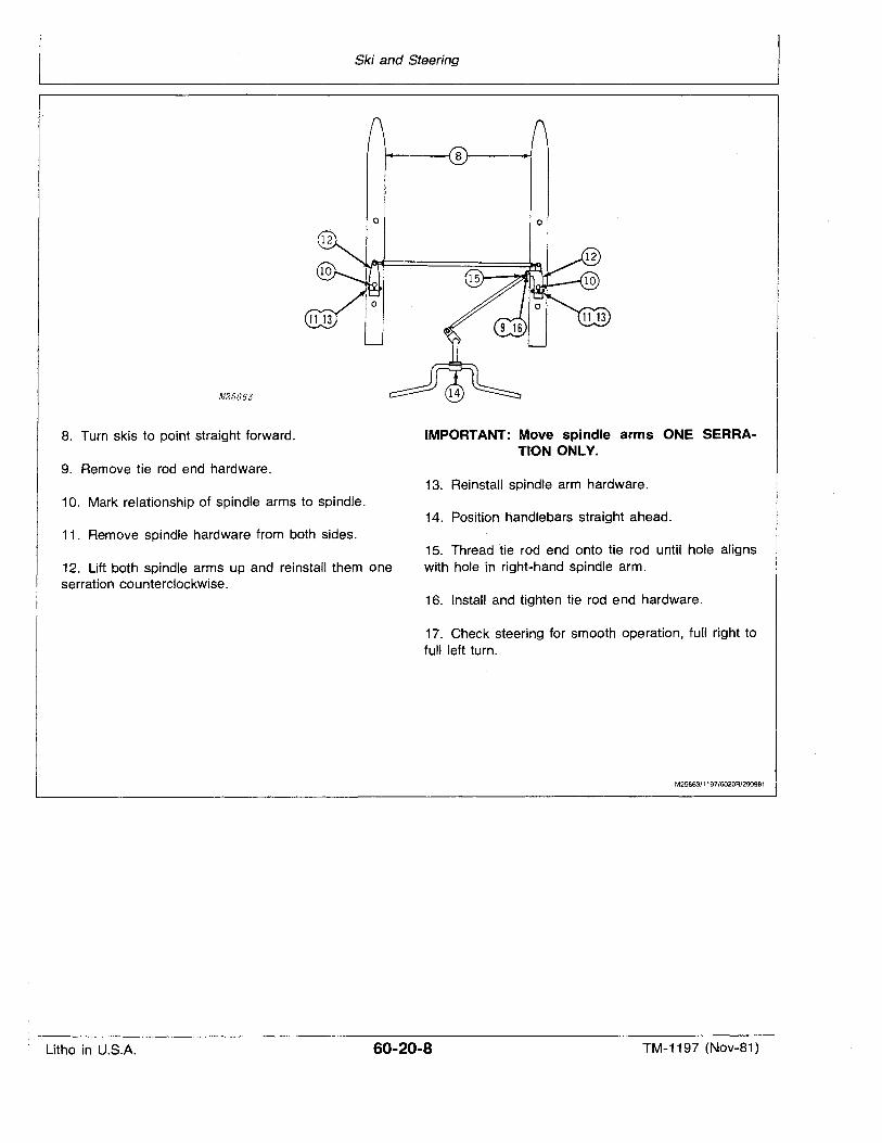
12
Ski and Steering
o o
M25663
8. Turn skis to point straight forward.
9. Remove tie rod end hardware.
IMPORTANT: Move spindle arms ONE SERRATION ONLY.
13. Reinstall spindle arm hardware.10. Mark relationship of spindle arms to spindle.
14. Position handlebars straight ahead.11. Remove spindle hardware from both sides.
12. Lift both spindle arms up and reinstall them oneserration counterclockwise.
15. Thread "tie rod end onto tie rod until hole alignswith hole in right-hand spindle arm.
16. Install and tighten tie rod end hardware.
17. Check steering for smooth operation, full right tofull left turn.
M25663/1197/6020R/290981
Litho in U.S.A. 60-20-8 TM-1197 (Nov-81)
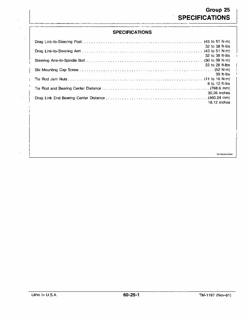
Group 2.5SPECIFICATIONS
SPECIFICATIONS
Drag Link-to-Steering Post (43 to 51 N·m)32 to 38 ft-Ibs
Drag Link-to-Steering Arm (43 to 51 N·m)32 to 38 ft-Ibs
Steering Arm-to-Spindle Bolt (30 to 38 N·m)22 to 28 ft-Ibs
Ski Mounting Cap Screw ~ (52 Nrn)39 ft-Ibs
Tie Rod Jam Nuts. . . . . . . . . . . . . . . . . . . . . . . . . . . . . . . . . . . . . . . . . . . . . . . . . . . . . . . . . (11 to 16 N·m)8 to 12 ft-Ibs
I Tie Rod and Bearing Center Distance (768.6 mm)30.26 inches
Drag Link End Bearing Center Distance (460.24 mm)18.12 inches
1197/6025A1250981
Litho in U.S.A. 60-25-1 TM-1197 (Nov-81)

Litho in U.S.A.
Specifications
TM-1'197 (Nov-81 )
Section 70SERVICE TOOLS
CONTENTS
GROUP 5 - ESSENTIAL SERVICE TOOLSGeneral . . . . . . . . . . . . . . . . . . . . . . . . . .70-05-1Engine Tools ...............•......70-05-1Clutch Tools 70-05-3Electrical Tools . . . . . . . . . . . . . . . . . . . .70-05-3
GROUP 10 - CONVENIENCE SERVICE TOOLSSnowmobile Support Tools 70-10-1Engine Tools 70-10-1Carburetor Tool 70-10-2
1197/7005N290981
Litho in U.S.A. 70-00-1 TM-1197 (Nov-81)

I,
Litho in U.S~A.
Contents
70-00-2 TM-1197 (Nov-81)
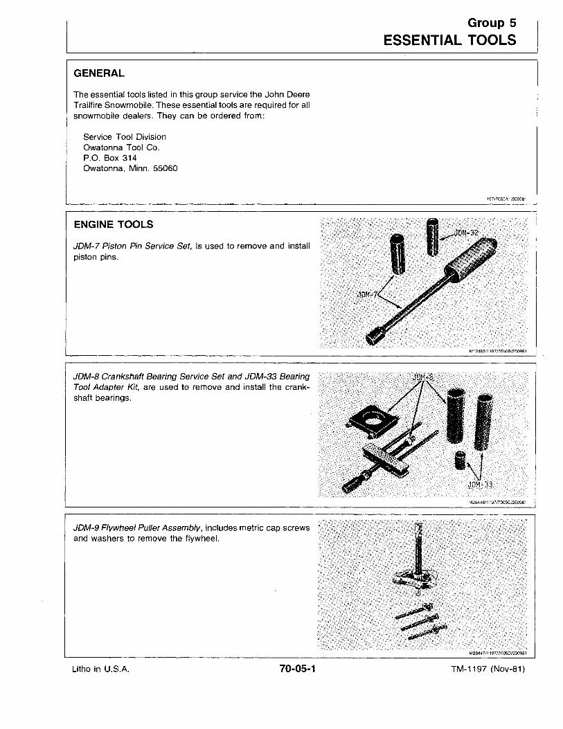
GENERAL
The essential tools listed in this group service the John DeereTrailfire Snowmobile. These essential tools are required for allsnowmobile dealers. They can be ordered from:
Service Tool DivisionOwatonna Tool Co.P.O. Box 314Owatonna, Minn. 55060
ENGINE TOOLS
JDM-7 Piston Pin Service Set, is used to remove and installpiston pins.
JDM-B Crankshaft Bearing Service Set and JDM-33 BearingTool Adapter Kit, are used to remove and install the crankshaft bearings.
JDM-9 Flywheel Puller Assembly, includes metric cap screwsand washers to remove the flywheel.
Group 5
ESSENTIAL TOOLS
1197/7005A1/250981
M12482/1197/7005B/250981
M28446/1197/7005C/2509B1
M28447/1197/7005D/290981
Litho in U.S.A. 70-05-1 TM-1197 (Nov-81)
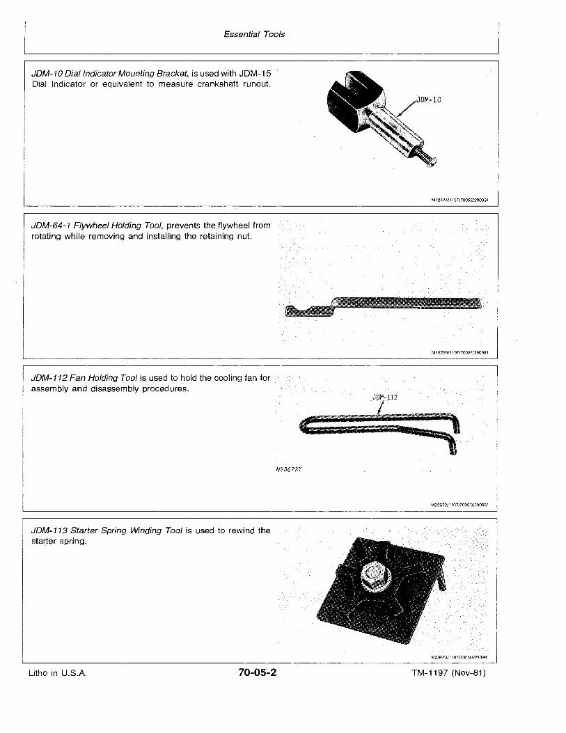
Essential Tools
JDM-10 Dial Indicator Mounting Bracket, is used with JDM-15 "Dial Indicator or equivalent to measure crankshaft runout.
M12474/1197/7005E/290981
JDM-64-1 Flywheel Holding Tool, prevents the flywheel fromrotating while removing and installing the retaining nut.
JDM-112 Fan Holding Tool is used to hold the cooling fan forassembly and disassembly procedures.
JDM-113 Starter Spring Winding Tool is used to rewind thestarter spring.
M18229/1197/7oo5F/290981
M23672/1197/7oo5G/290981
M23673/1197/7005H/290981
Litho in U.S.A. 70-05-2 TM-1197 (Nov-81)
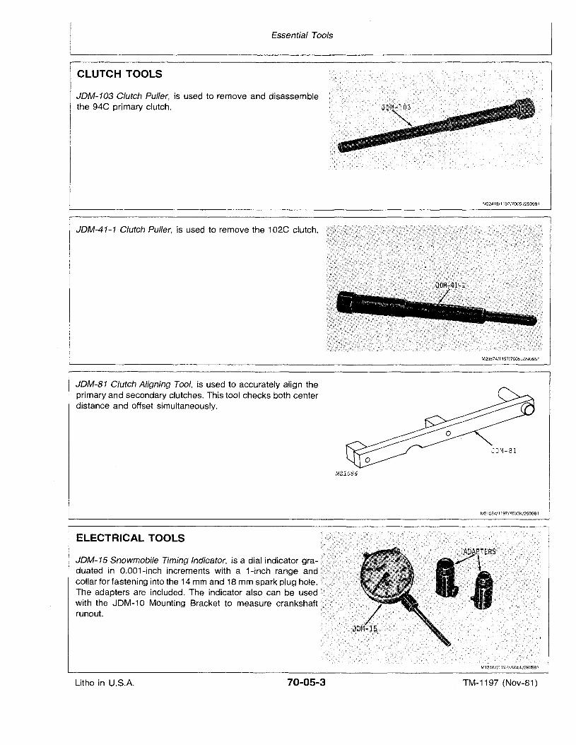
Essential Tools
CLUTCH TOOLS
JDM-103 Clutch Puller, is used to remove and disassemblethe 94C primary clutch.
M22413/1197/70051/290981
JDM-41-1 Clutch Puller, is used to remove the 102C clutch. .... ::..:<....;...:>.:..
....;.:: ' ..':.(: ..:
M23674/1197 /7005J/290981
JDM-81 Clutch Aligning Tool, is used to accurately align theprimary and secondary clutches. This tool checks both centerdistance and offset simultaneously.
M21084
M21084/1197/7005K/290981
ELECTRICAL TOOLS
JDM-15Sno~ob~TIm~g~~a~~isadi~ind~~mgffi-~~~~~~~~~~~~~~~~~~~~Iduated in O.001-inch increments with a 1-inch range and :~Icollar for fastening into the 14 mm and 18 mm spark plug hole. iii;';;;!:/d/i!:I;!
The adapters are included. The indicator also can be used
runout.
M12487/1197/7005L/290981
Litho in U.S.A. 70-05-3 TM-1197 (Nov-81)
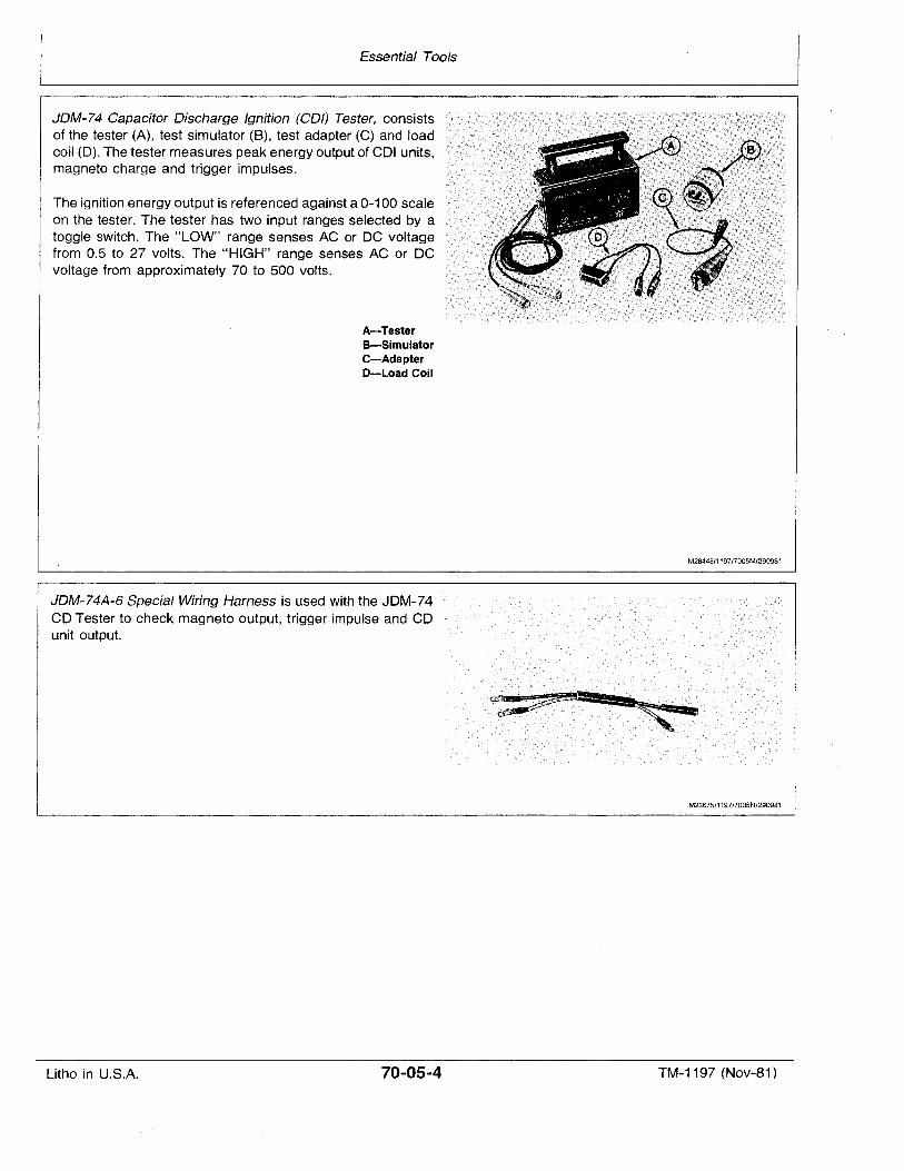
Essential Tools
JDM-74 Capacitor Discharge Ignition (COl) Tester, consistsof the tester (A), test simulator (8), test adapter (C) and loadcoil (D). The tester measures peak energy output of COl units,magneto charge and trigger impulses.
The ignition energy output is referenced against a 0-100 scaleon the tester. The tester has two input ranges selected by atoggle switch. The "LOW" range senses AC or DC voltagefrom 0.5 to 27 volts. The "HIGH" range senses AC or DCvoltage from approximately 70 to 500 volts.
A-TesterB-SimulatorC-AdapterD-Load Coil
M28448/1197/7005M/290981
JDM-74A-6 Special Wiring Harness is used with the JDM-74CfrTester to check magneto output, trigger impulse and CDunit output.
M23675/1197/7005N/290981
Litho in U.S.A. 70-05-4 TM-1197 (Nov-81)

Litho in U.S.A.
Essential Tools
70-05..5 TM-1197 (Nov-81)

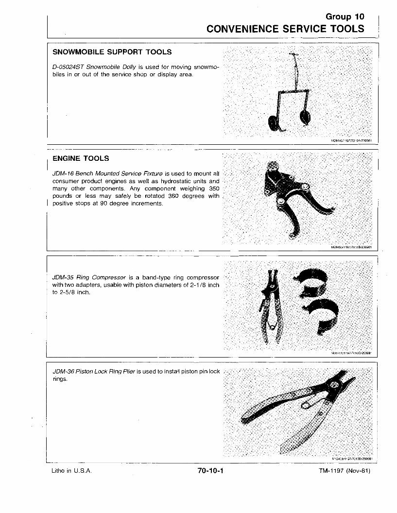
Group 10
CONVENIENCE SERVICE TOOLS
SNOWMOBILE SUPPORT TOOLS
0-05024S7 Snowmobile Dolly is used for moving snowmobiles in or out of the service shop or display area.
M28449/1197/701 OA/2909B1
ENGINE TOOLS
JOM-16 Bench Mounted Service Fixture is used to mount all
many other components. Any component weighing 350 jl~ill~llllil!\~j[~~!~!I!~;Il!11pounds or less may safely be rotated 360 degrees withpositive stops at 90 degree increments.
JDM-35 Ring Compressor is a band-type ring compressorwith two adapters, usable with piston diameters of 2-1 /8 inchto 2-5/8 inch.
JDM-36 Piston Lock Ring Plier is used to install piston pin lockrings.
M12493/1197/7010D/290981
Litho in U.S.A. 70-10-1 TM-1197 (Nov-81)
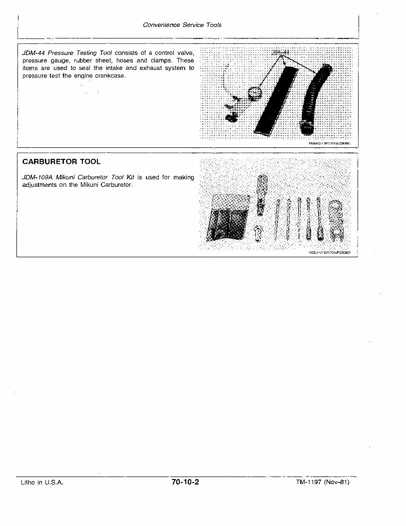
Convenience Service Tools
JDM-44 Pressure Testing Tool consists of a control valve,pressure gauge, rubber sheet, hoses ·and clamps. Theseitems are used to seal the intake and exhaust system topressure test the enqine crankcase.
CARBURETOR TOOL
JDM-109A Mikuni Carburetor Tool Kit is used for makingadjustments on the Mikuni Carburetor.
M28452/1197/7010E/290981
M25311/1197/7010F/250981
Litho in U.S.A. 70-10-2 TM-1197 (Nov-81)