Embed Size (px)
Citation preview

SECTION 5: CONCRETE STRUCTURES CALIFORNIA AMENDMENTS TO AASHTO LRFD BRIDGE DESIGN SPECIFICATIONS – FOURTH EDITION 5-12A
5.4.2.1 Compressive Strength Revise the 3rd paragraph as follows:
The specified compressive strength for prestressed concrete and decks shall not be less than 4.0 ksi. The specified compressive concrete strength shall not be less than 3.6 ksi for reinforced concrete.
December 2008

SECTION 5: CONCRETE STRUCTURES CALIFORNIA AMENDMENTS TO AASHTO LRFD BRIDGE DESIGN SPECIFICATIONS – FOURTH EDITION 5-12B
This page is intentionally left blank.
December 2008

SECTION 5: CONCRETE STRUCTURES CALIFORNIA AMENDMENTS TO AASHTO LRFD BRIDGE DESIGN SPECIFICATIONS – FOURTH EDITION 5-23A
5.5.3.1 General Revise the 2nd Paragraph as follows:
In regions of compressive stress due to permanent loads and prestress in reinforced and partially prestressed concrete components, fatigue shall be considered only if this compressive stress is less than twice the maximum tensile live load stress resulting from the Ffatigue I load combination for finite fatigue life as specified in Table 3.4.1-1 in combination with the provisions of Article 3.6.1.4.
Insert the following after the 3rd Paragraph:
Where consideration of fatigue is required, the stress range shall be determined using the Fatigue I load combination for infinite fatigue life as specified in Table 3.4.1-1. Revise the 4th Paragraph as follows:
The section properties for fatigue investigations
shall be based on cracked sections where the sum of stresses, due to unfactored permanent loads and prestress, and 1.75 times the fatigue load of Fatigue I is tensile and exceeds 0.095√f′c.
5.5.3.2 Reinforcing Bars
Revise the 1st Paragraph as follows:
The stress range in straight reinforcement and welded wire reinforcement without a cross weld in the high-stress region resulting from the Ffatigue I load combination for infinite fatigue life, specified in Table 3.4.1-1, shall satisfy:
C5.5.3.1
Revise the 2nd Paragraph as follows:
In determining the need to investigate fatigue, Table 3.4.1-1 specifies a load factor of 0.875 on the live load force effect resulting from the fatigue truck. The factor 2.0 specified in this Article is applied to the factored live load for a total of 1.750 times the unfactored force effect from the fatigue truck for infinite fatigue life.
December 2008
SECTION 5: CONCRETE STRUCTURES CALIFORNIA AMENDMENTS TO AASHTO LRFD BRIDGE DESIGN SPECIFICATIONS – FOURTH EDITION 5-24A
5.5.3.3 Prestressing Tendons
Revise the 1st Paragraph as follows: The stress range in prestressing tendons resulting
from the Fatigue I load combination for infinite fatigue life, specified in Table 3.4.1-1, shall not exceed:
5.5.3.4 Welded or Mechanical Splices of Reinforcement
Revise the 1st Paragraph as follows:
For welded or mechanical connections that are subject to repetitive loads, the range of stress, ff, resulting from the Fatigue I load combination for infinite fatigue life, and the Fatigue II load combination for finite fatigue life specified in Table 3.4.1-1, shall not exceed the nominal fatigue resistance given in Table 1. Table 5.5.3.4-1 Nominal Fatigue Resistance of Splices. Revise Table 5.5.3.4-1 as follows: Table 5.5.3.4-1 Nominal Fatigue Resistance of Splices.
Type of Splice
fffor greater
than 1,000,000
cycles Grout-filled sleeve, with or without epoxy coated bar
18 ksi
Cold-swaged coupling sleeves without threaded ends and with or without epoxy-coated bar; Integrally-forged coupler with upset NC threads; Steel sleeve with a wedge; One-piece taper-threaded coupler; and Single V-groove direct butt weld
12 ksi
All other types of splices 4 ksi Revise the 2nd Paragraph as follows:
Where the total cycles of loading, Ncyc, are less than 1 million, nominal fatigue resistance of splices specified in Table 1 .ff may be increased by the quantity 24 (6−logNcyc) ksi to a total not greater than the value of ff given by the right side of Eq. 5.5.3.2-1 in Article 5.5.3.2. Higher values of nominal fatigue resistance ff, up to the value given by the right side of Eq. 5.5.3.2-1, may be used if justified by fatigue test data on splices that are the same as those that will be placed in service.
December 2008

SECTION 5: CONCRETE STRUCTURES CALIFORNIA AMENDMENTS TO AASHTO LRFD BRIDGE DESIGN SPECIFICATIONS – FOURTH EDITION 5-25A
5.5.4.2.1 Conventional Construction
Add a new 2nd “bullet” as follows: h For tension-controlled cast-in-place
prestressed concrete sections as defined in Article 5.7.2.1.............................................0.95
December 2008

SECTION 5: CONCRETE STRUCTURES CALIFORNIA AMENDMENTS TO AASHTO LRFD BRIDGE DESIGN SPECIFICATIONS – FOURTH EDITION 5-26A
C5.5.4.2.1
Delete Fig. C5.5.4.2.1-1 and replace with the following:
Precast Prestressed Members φ = 0.75 + 83.33(εt – 0.002) Cast-in-Place Prestressed Members
( ) 0020676675 ... t −+ ε0=φ0.95
Non Prestressed Members ( )00200050750 ... t= + ε −φ
Figure C5.5.4.2.1-1 – Variation of φ with net tensile strain εt for Grade 60 reinforcement and for prestresseding members steel.
December 2008

SECTION 5: CONCRETE STRUCTURES CALIFORNIA AMENDMENTS TO AASHTO LRFD BRIDGE DESIGN SPECIFICATIONS – FOURTH EDITION 5-28A
5.5.5 Extreme Event Limit State
Revise as follows:
The structure as a whole and its components shall be proportioned to resist collapse due to extreme events, specified in Table 3.4.1-1, as may be appropriate to its site and use. Resistance factors shall be 1.0.
December 2008

SECTION 5: CONCRETE STRUCTURES CALIFORNIA AMENDMENTS TO AASHTO LRFD BRIDGE DESIGN SPECIFICATIONS – FOURTH EDITION 5-28B
This page is intentionally left blank.
December 2008
SECTION 5: CONCRETE STRUCTURES CALIFORNIA AMENDMENTS TO AASHTO LRFD BRIDGE DESIGN SPECIFICATIONS – FOURTH EDITION 5-37A
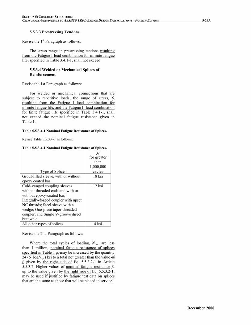
5.7.2.1 General Revise the 11th “bullet” as follows:
• Sections are tension-controlled when the net tensile strain in the extreme tension steel is equal to or greater than 0.005 just as the concrete in compression reaches its assumed strain limit of 0.003. Sections with net tensile strain in the extreme tension steel between the compression-controlled strain limit and 0.005 constitute a transition region between compression-controlled and tension-controlled sections. For non-prestressed concrete flexural sections including girders, bent caps, and deck slabs, the net-tensile strain in the extreme tension steel shall not be less than 0.004.
C5.7.2.1 Revise the 4th Paragraph as follows:
When the net tensile strain in the extreme tension
steel is sufficiently large (equal to or greater than 0.005), the section is defined as tension-controlled where ample warning of failure with excessive deflection and cracking may be expected. When the net tensile strain in the extreme tension steel is small (less than or equal to the compression-controlled strain limit), a brittle failure condition may be expected, with little warning of impending failure. Flexural members are usually tension-controlled, while compression members are usually compression-controlled. Ensuring that the net tensile strain in the extreme tensile steel is not less than 0.004 is equivalent to the previously established practice of limiting the maximum reinforcement ratio in a cross section to 0.75 times the balanced reinforcement ratio. Some sections, such as those with small axial load and large bending moment, will have net tensile strain in the extreme tension steel between the above limits. These sections are in a transition region between compression- and tension-controlled sections. Article 5.5.4.2.1 specifies the appropriate resistance factors for tension-controlled and compression-controlled sections, and for intermediate cases in the transition region.
December 2008

SECTION 5: CONCRETE STRUCTURES CALIFORNIA AMENDMENTS TO AASHTO LRFD BRIDGE DESIGN SPECIFICATIONS – FOURTH EDITION 5-37B
This page is intentionally left blank.
December 2008
SECTION 5: CONCRETE STRUCTURES CALIFORNIA AMENDMENTS TO AASHTO LRFD BRIDGE DESIGN SPECIFICATIONS – FOURTH EDITION 5-47A
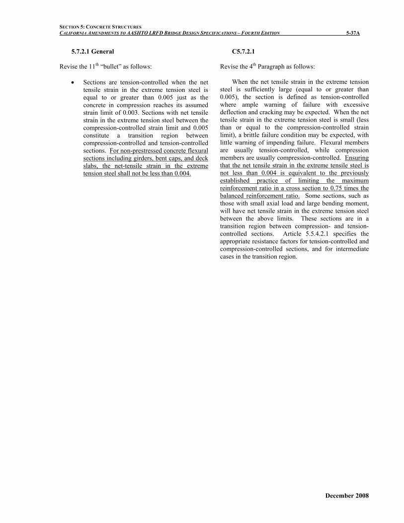
5.7.3.4 Control of Cracking by Distribution of Reinforcement
Revise the 3rd Paragraphs as follows:
Class 1 exposure condition applies when cracks can be tolerated due to reduced concerns of appearance and/or corrosion. Class 2 exposure condition applies to transverse design of segmental concrete box girders for any loads applied prior to attaining full nominal concrete strength and when there is increased concern of appearance and/or corrosion.
Add a new Paragraph after the 3rd Paragraph:
Class 2 exposure condition applies to all bridge
decks. The concrete cover dc, shall be taken as 2-1/2 in. in Eq.1 when verifying reinforcement spacing in bridge decks.
December 2008

SECTION 5: CONCRETE STRUCTURES CALIFORNIA AMENDMENTS TO AASHTO LRFD BRIDGE DESIGN SPECIFICATIONS – FOURTH EDITION 5-48A
5.7.3.6.2 Deflection and Camber Revise the 1st Paragraph as follows:
Instantaneous dDeflection and camber calculations shall consider appropriate combinations of dead load, live load, prestressing forces, erection loads, concrete creep and shrinkage, and steel relaxation. Add a 2nd Paragraph as follows:
Long-term deflection calculations to estimate camber shall consider deflections due to appropriate combinations of all the above mentioned load effects except for those due to live load.
C5.7.3.6.2 Revise the 1st Paragraph as follows:
"Camber" is the deflection built into a member, other than by prestressing, in order to achieve a desired grade. For structures such as segmentally constructed bridges, camber calculations should be based on the modulus of elasticity and the maturity of the concrete when each increment of load is added or removed, as specified in Articles 5.4.2.3 and 5.14.2.3.6. Add a new 2nd Paragraph as follows:
Past experiences with cast-in-place box girder bridges show that the design predictions of camber based on Ig are generally in conformance with field-measured values.
December 2008

SECTION 5: CONCRETE STRUCTURES CALIFORNIA AMENDMENTS TO AASHTO LRFD BRIDGE DESIGN SPECIFICATIONS – FOURTH EDITION 5-49A
5.7.3.6.2 Deflection and Camber Delete the 5th Paragraph and replace with the following:
Unless a more exact determination is made, the long-time deflection may be taken as the instantaneous deflection multiplied by the following factor:
• If the instantaneous deflection is based on Ig:
4.0 • If the instantaneous deflection is based on Ie:
3.0-1.2(A’s/As) >=1.6
Long-term deflection of cast-in-place structures may be calculated by multiplying the instantaneous deflection values based on Ig with the following factors:
• For nonprestressed concrete structures: 4.0 • For prestressed concrete structures: 3.0
Alternatively, long-term deflection of cast-in-place non-prestressed concrete structures may be calculated by multiplying the instantaneous deflection values based on Ie with the following factor: 3.0 – 1.2(A’g/As) ≥ 1.6 (5.7.3.6.2-3) where: A’
s = area of compression reinforcement (in2) As = area of nonprestressed tension reinforcement
(in2)
C5.7.3.6.2 Revise the last Paragraph as follows: In prestressed concrete, the long-term deflection is usually may be based on mix-specific data where available, possibly in combination with the calculation procedures in Article 5.4.2.3. Other methods of calculating deflections which consider the different types of loads and the sections to which they are applied, such as that found in (PCI 1992), may also be used.
December 2008

SECTION 5: CONCRETE STRUCTURES CALIFORNIA AMENDMENTS TO AASHTO LRFD BRIDGE DESIGN SPECIFICATIONS – FOURTH EDITION 5-49B
This page is intentionally left blank.
December 2008
SECTION 5: CONCRETE STRUCTURES CALIFORNIA AMENDMENTS TO AASHTO LRFD BRIDGE DESIGN SPECIFICATIONS – FOURTH EDITION 5-60A
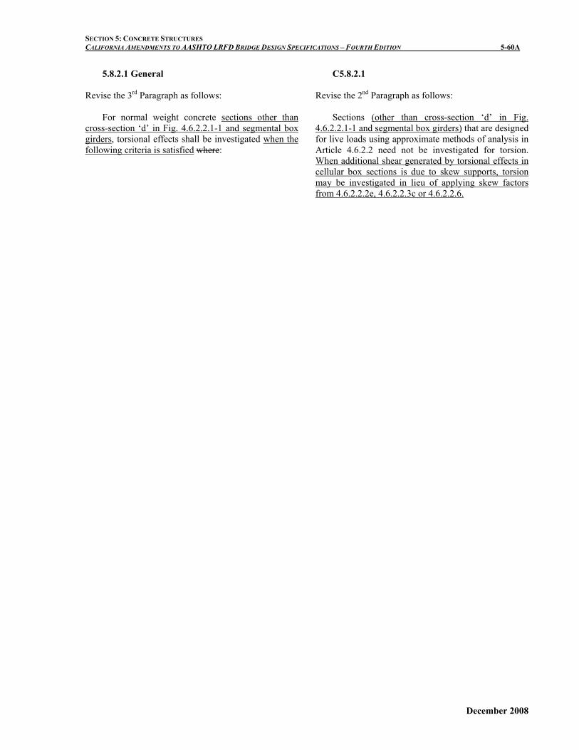
5.8.2.1 General Revise the 3rd Paragraph as follows:
For normal weight concrete sections other than cross-section ‘d’ in Fig. 4.6.2.2.1-1 and segmental box girders, torsional effects shall be investigated when the following criteria is satisfied where:
C5.8.2.1 Revise the 2nd Paragraph as follows:
Sections (other than cross-section ‘d’ in Fig. 4.6.2.2.1-1 and segmental box girders) that are designed for live loads using approximate methods of analysis in Article 4.6.2.2 need not be investigated for torsion. When additional shear generated by torsional effects in cellular box sections is due to skew supports, torsion may be investigated in lieu of applying skew factors from 4.6.2.2.2e, 4.6.2.2.3c or 4.6.2.2.6.
December 2008

SECTION 5: CONCRETE STRUCTURES CALIFORNIA AMENDMENTS TO AASHTO LRFD BRIDGE DESIGN SPECIFICATIONS – FOURTH EDITION 5-60B
This page is intentionally left blank.
December 2008

SECTION 5: CONCRETE STRUCTURES CALIFORNIA AMENDMENTS TO AASHTO LRFD BRIDGE DESIGN SPECIFICATIONS – FOURTH EDITION 5-61A
5.8.2.1 General
Add the following after the 3rd Paragraph:
For cross-section ‘d’ in Fig. 4.6.2.2.1-1 and segmental box sections, torsional effects on individual girders shall be investigated at all times.
Revise the 4th Paragraph as follows:
The equivalent factored shear force, VuT, shall be taken equal to:
For solid sections:
22
29.0
⎟⎟⎠
⎞⎜⎜⎝
⎛+
o
uhu A
TpVVuT = (5.8.2.1-6)
For the individual web/girder of a box sections the combined torsion and shear force is taken from analysis methods defined in Articles 4.6.2 or 4.6.3, or: VuT = Vui +
o
su
AdT
2 (5.8.2.1-7)
where: ph = perimeter of the centerline of the closed
transverse torsional moment reinforcement (kip-in.)
Tu = factored torsional moment applied to the entire
box section (kip-in.) Vui = factored shear force in the controlling
web/girder of the box section VuT = factored shear force from combined torsion
and shear effects acting on the controlling web/girder of the box section of equivalent factored shear force from combined torsion and shear effects acting on the individual solid section.
December 2008

SECTION 5: CONCRETE STRUCTURES CALIFORNIA AMENDMENTS TO AASHTO LRFD BRIDGE DESIGN SPECIFICATIONS – FOURTH EDITION 5-62A
C5.8.2.1 Revise the 7th Paragraph as follows:
In box girders, torsion introduces shear forces in the webs as well as in the top and bottom slab. In most box girder sections, the torsional shear in interior girder webs will be negligible and is primarily resisted by exterior girders. For a box girder, tThe shear flow due to torsion is added to the shear flow due to flexure in one exterior web and subtracted from shear flow due to flexure in the opposite exterior web. In the controlling web, the second term in Eq. 7 comes from integrating the distance from the centroid of the section to the center of the shear flow path around the circumference of the section. The stress is converted to a force by multiplying the shear flow by the web height measured between the shear flow paths in the top and bottom slabs., This height may be conservatively taken as h since calculating the value of ds would be cumbersome which has a value approximately equal to that of ds. If the exterior girder web is sloped this distance should be divided by the sine of the web angle from horizontal.
December 2008

SECTION 5: CONCRETE STRUCTURES CALIFORNIA AMENDMENTS TO AASHTO LRFD BRIDGE DESIGN SPECIFICATIONS – FOURTH EDITION 5-66A
5.8.2.9 Shear Stress on Concrete
Revise the 2nd Paragraph as follows:
In determining the web width at a particular level, one-half the diameters of ungrouted ducts or one-quarter the diameter of grouted ducts at that level shall be subtracted from the web width. It is not necessary to reduce bv for the presence of ducts in fully grouted cast-in-place box girder frames.
C5.8.2.9
Revise the 1st Paragraph as follows:
For flexural members complying with Eq. 5.7.3.3.1-1, the distance between the resultants of the tensile and compressive forces due to flexure can be determined as:
pspsys
nv fAfA
Md+
=
The effective depth from extreme compression
fiber to the centroid of tensile force in the tensile reinforcement can be determined as:
sspsps
sssppspse fAfA
dfAdfAd
+
+= (C5.8.2.9-1)
December 2008

SECTION 5: CONCRETE STRUCTURES CALIFORNIA AMENDMENTS TO AASHTO LRFD BRIDGE DESIGN SPECIFICATIONS – FOURTH EDITION 5-66B
This page is intentionally left blank.
December 2008
SECTION 5: CONCRETE STRUCTURES CALIFORNIA AMENDMENTS TO AASHTO LRFD BRIDGE DESIGN SPECIFICATIONS – FOURTH EDITION 5-75A
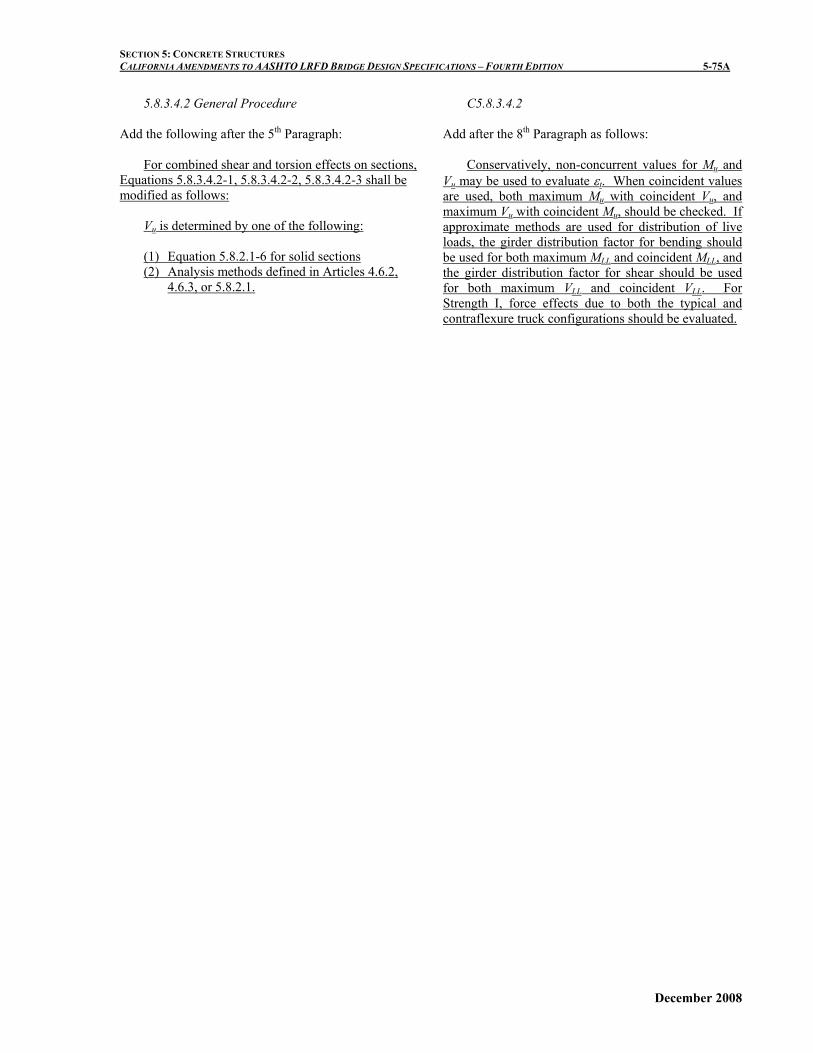
5.8.3.4.2 General Procedure
Add the following after the 5th Paragraph: For combined shear and torsion effects on sections,
Equations 5.8.3.4.2-1, 5.8.3.4.2-2, 5.8.3.4.2-3 shall be modified as follows:
Vu is determined by one of the following: (1) Equation 5.8.2.1-6 for solid sections (2) Analysis methods defined in Articles 4.6.2,
4.6.3, or 5.8.2.1.
C5.8.3.4.2
Add after the 8th Paragraph as follows:
Conservatively, non-concurrent values for Mu and Vu may be used to evaluate εt. When coincident values are used, both maximum Mu with coincident Vu, and maximum Vu with coincident Mu, should be checked. If approximate methods are used for distribution of live loads, the girder distribution factor for bending should be used for both maximum MLL and coincident MLL, and the girder distribution factor for shear should be used for both maximum VLL and coincident VLL. For Strength I, force effects due to both the typical and contraflexure truck configurations should be evaluated.
December 2008

SECTION 5: CONCRETE STRUCTURES CALIFORNIA AMENDMENTS TO AASHTO LRFD BRIDGE DESIGN SPECIFICATIONS – FOURTH EDITION 5-75B
This page is intentionally left blank.
December 2008

SECTION 5: CONCRETE STRUCTURES CALIFORNIA AMENDMENTS TO AASHTO LRFD BRIDGE DESIGN SPECIFICATIONS – FOURTH EDITION 5-80A
5.8.3.4.3 Simplified Procedure for Prestressed and Nonprestressed Sections
Delete entire Article and revise as follows:
Article 5.8.3.4.3 “Simplified Procedure for
Prestressed and Nonprestressed Sections shall not be used.
December 2008

SECTION 5: CONCRETE STRUCTURES CALIFORNIA AMENDMENTS TO AASHTO LRFD BRIDGE DESIGN SPECIFICATIONS – FOURTH EDITION 5-80B
This page is intentionally left blank.
December 2008
SECTION 5: CONCRETE STRUCTURES CALIFORNIA AMENDMENTS TO AASHTO LRFD BRIDGE DESIGN SPECIFICATIONS – FOURTH EDITION 5-82A
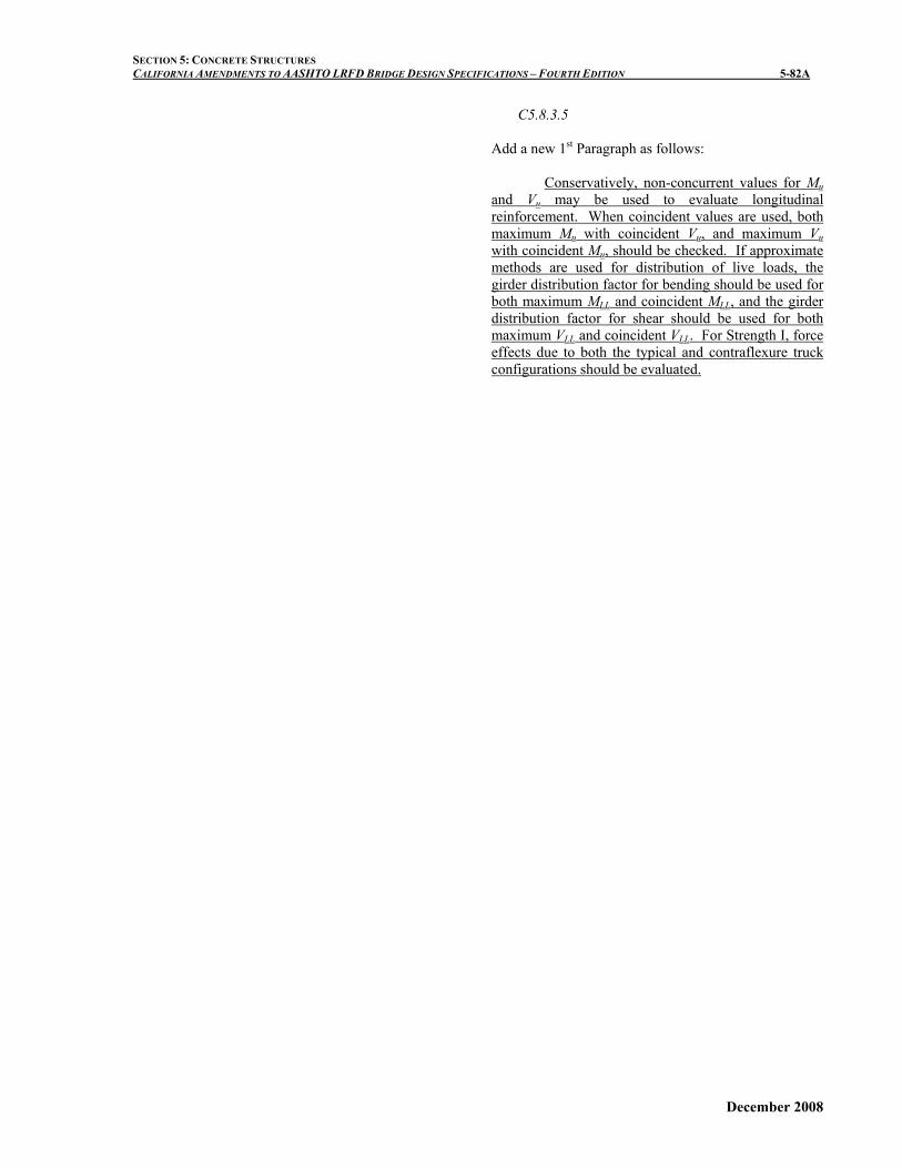
C5.8.3.5
Add a new 1st Paragraph as follows: Conservatively, non-concurrent values for Mu and Vu may be used to evaluate longitudinal reinforcement. When coincident values are used, both maximum Mu with coincident Vu, and maximum Vu with coincident Mu, should be checked. If approximate methods are used for distribution of live loads, the girder distribution factor for bending should be used for both maximum MLL and coincident MLL, and the girder distribution factor for shear should be used for both maximum VLL and coincident VLL. For Strength I, force effects due to both the typical and contraflexure truck configurations should be evaluated.
December 2008

SECTION 5: CONCRETE STRUCTURES CALIFORNIA AMENDMENTS TO AASHTO LRFD BRIDGE DESIGN SPECIFICATIONS – FOURTH EDITION 5-82B
This page is intentionally left blank.
December 2008

SECTION 5: CONCRETE STRUCTURES CALIFORNIA AMENDMENTS TO AASHTO LRFD BRIDGE DESIGN SPECIFICATIONS – FOURTH EDITION 5-84A
5.8.3.6.1 Transverse Reinforcement
Revise as follows: For sections other than cross-section ‘d’ in Fig.
4.6.2.2.1-1 and segmental box girders, tThe transverse reinforcement shall not be less than the sum of that required for shear, as specified in Article 5.8.3.3, and for the concurrent torsion, as specified in Articles 5.8.2.1 and 5.8.3.6.2.
For cast-in-place and segmental box sections, the total transverse reinforcement, Av for the individual girder shall be designed to satisfy:
nuT VV φ≤ (5.8.3.6.1-1)
where: Vn is specified in Article 5.8.3.3 and the cross-sectional dimension of the girder shall satisfy the following:
'474.02 c
eo
u
vv
u fbA
Tdb
V≤⎟⎟
⎠
⎞⎜⎜⎝
⎛+⎟⎟
⎠
⎞⎜⎜⎝
⎛ (5.8.3.6.1-2)
C5.8.3.6.1
Add the following after the 2nd Paragraph: Equation 5.8.3.6.1-2 is used to check the cross
section dimension to prevent concrete crushing before yielding of steel stirrups.
C5.8.3.6.2 For cast-in-place and segmental box sections, At
defined in Eq. 1 is used to determine the portions of transverse reinforcement determined in Article 5.8.3.6.1 that needs to be closed hoops or 135-degree hooks.
December 2008

SECTION 5: CONCRETE STRUCTURES CALIFORNIA AMENDMENTS TO AASHTO LRFD BRIDGE DESIGN SPECIFICATIONS – FOURTH EDITION 5-84B
This page is intentionally left blank.
December 2008

SECTION 5: CONCRETE STRUCTURES CALIFORNIA AMENDMENTS TO AASHTO LRFD BRIDGE DESIGN SPECIFICATIONS – FOURTH EDITION 5-87A
5.8.4.1 General Revise the 6th Paragraph as follows: where: c = cohesion factor specified in Article 5.8.4.3
(ksi), c = 0 when designing for extreme limit states
December 2008

SECTION 5: CONCRETE STRUCTURES CALIFORNIA AMENDMENTS TO AASHTO LRFD BRIDGE DESIGN SPECIFICATIONS – FOURTH EDITION 5-87B
This page is intentionally left blank.
December 2008

SECTION 5: CONCRETE STRUCTURES CALIFORNIA AMENDMENTS TO AASHTO LRFD BRIDGE DESIGN SPECIFICATIONS – FOURTH EDITION 5-92A
5.8.6 Shear and Torsion for Segmental Box Girder Bridges Delete all the provisions in Article 5.8.6 and replace with the following:
Articles 5.8.1, 5.8.2, 5.8.3, 5.8.4, and 5.8.5 shall be used for shear and torsion design of segmental post-tensioned box girders bridges.
December 2008

SECTION 5: CONCRETE STRUCTURES CALIFORNIA AMENDMENTS TO AASHTO LRFD BRIDGE DESIGN SPECIFICATIONS – FOURTH EDITION 5-92B
This page is intentionally left blank.
December 2008
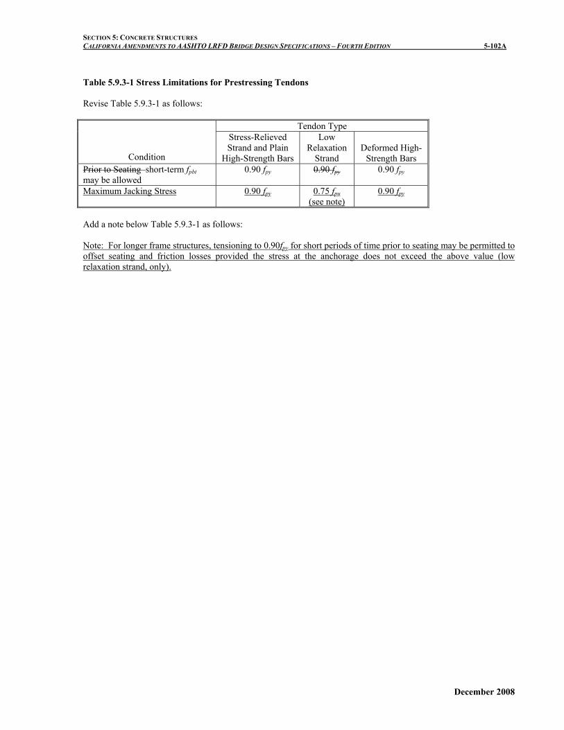
SECTION 5: CONCRETE STRUCTURES CALIFORNIA AMENDMENTS TO AASHTO LRFD BRIDGE DESIGN SPECIFICATIONS – FOURTH EDITION 5-102A Table 5.9.3-1 Stress Limitations for Prestressing Tendons Revise Table 5.9.3-1 as follows:
Tendon Type
Condition
Stress-Relieved Strand and Plain
High-Strength Bars
Low Relaxation
Strand Deformed High-
Strength Bars Prior to Seating–short-term fpbt may be allowed
0.90 fpy 0.90 fpy 0.90 fpy
Maximum Jacking Stress 0.90 fpy 0.75 fpu (see note)
0.90 fpy
Add a note below Table 5.9.3-1 as follows: Note: For longer frame structures, tensioning to 0.90fpy for short periods of time prior to seating may be permitted to offset seating and friction losses provided the stress at the anchorage does not exceed the above value (low relaxation strand, only).
December 2008

SECTION 5: CONCRETE STRUCTURES CALIFORNIA AMENDMENTS TO AASHTO LRFD BRIDGE DESIGN SPECIFICATIONS – FOURTH EDITION 5-102B
This page is intentionally left blank.
December 2008
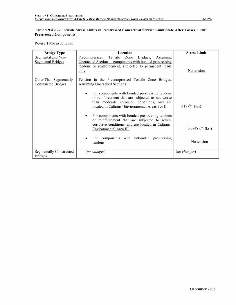
SECTION 5: CONCRETE STRUCTURES CALIFORNIA AMENDMENTS TO AASHTO LRFD BRIDGE DESIGN SPECIFICATIONS – FOURTH EDITION 5-107A Table 5.9.4.2.2-1 Tensile Stress Limits in Prestressed Concrete at Service Limit State After Losses, Fully Prestressed Components Revise Table as follows:
Bridge Type Location Stress Limit Segmental and Non-Segmental Bridges
Precompresssed Tensile Zone Bridges, Assuming Uncracked Sections—components with bonded prestressing tendons or reinforcement, subjected to permanent loads only.
No tension
Other Than Segmentally Constructed Bridges
Tension in the Precompressed Tensile Zone Bridges, Assuming Uncracked Sections
• For components with bonded prestressing tendons or reinforcement that are subjected to not worse than moderate corrosion conditions, and are located in Caltrans’ Environmental Areas I or II.
• For components with bonded prestressing tendons
or reinforcement that are subjected to severe corrosive conditions, and are located in Caltrans’ Environmental Area III.
• For components with unbonded prestressing
tendons.
0.19√f’c (ksi) 0.0948√f’c (ksi) No tension
Segmentally Constructed Bridges
(no changes) (no changes)
December 2008

SECTION 5: CONCRETE STRUCTURES CALIFORNIA AMENDMENTS TO AASHTO LRFD BRIDGE DESIGN SPECIFICATIONS – FOURTH EDITION 5-107B
This page is intentionally left blank.
December 2008

SECTION 5: CONCRETE STRUCTURES CALIFORNIA AMENDMENTS TO AASHTO LRFD BRIDGE DESIGN SPECIFICATIONS – FOURTH EDITION 5-111A
C5.9.5.2.2b
Add a new last Paragraph:
For tendon lengths greater than 1200 feet, investigation is warranted on current field data of similar length frame bridges for appropriate values of μ.
Revise as follows: Table 5.9.5.2.2b-1 Friction Coefficients for Post-Tensioning Tendons
Type of Steel Type of Duct K /ft μ Rigid and semi-rigid galvanized metal sheathing
0.0002 0.15-0.25
Tendon Length: < 600 ft 0.0002 0.15 600 ft < 900 ft 0.0002 0.20 900 ft < 1200 ft 0.0002 0.25 > 1200 ft 0.0002 >0.25 Polyethylene 0.0002 0.23
Wire or strand
Rigid steel pipe deviators for external tendons
0.0002 0.25
High-strength bars
Galvanized metal sheathing
0.0002 0.30
December 2008

SECTION 5: CONCRETE STRUCTURES CALIFORNIA AMENDMENTS TO AASHTO LRFD BRIDGE DESIGN SPECIFICATIONS – FOURTH EDITION 5-111B
This page is intentionally left blank.
December 2008
SECTION 5: CONCRETE STRUCTURES CALIFORNIA AMENDMENTS TO AASHTO LRFD BRIDGE DESIGN SPECIFICATIONS – FOURTH EDITION 5-113A
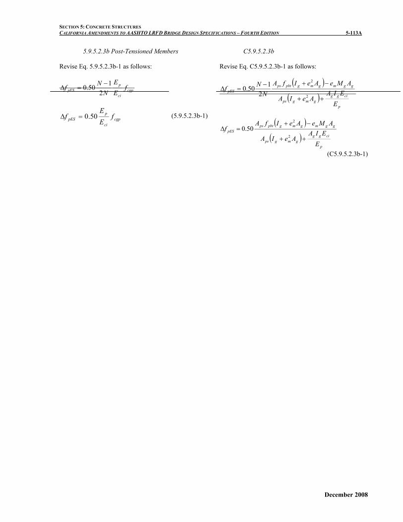
5.9.5.2.3b Post-Tensioned Members Revise Eq. 5.9.5.2.3b-1 as follows:
cgpci
ppES f
EE
NNf2
150.0 −=Δ
cgpci
ppES f
EE
f 50.0=Δ (5.9.5.2.3b-1)
C5.9.5.2.3b Revise Eq. C5.9.5.2.3b-1 as follows:
( )( )
p
cigggmgps
ggmgmgpbtpspES
EEIA
AeIA
AMeAeIfAN
Nf++
−+−=Δ
2
2
2150.0
( )
( )p
cigggmgps
ggmgmgpbtpspES
EEIA
AeIA
AMeAeIfAf
++
−+=Δ
2
2
50.0
(C5.9.5.2.3b-1)
December 2008

SECTION 5: CONCRETE STRUCTURES CALIFORNIA AMENDMENTS TO AASHTO LRFD BRIDGE DESIGN SPECIFICATIONS – FOURTH EDITION 5-114A
5.9.5.3 Approximate Estimate of Time-Dependent Losses
Add a new last Paragraph:
For post-tensioned members, the approximate estimate of time-dependent losses may be taken as the lump sum value of 25 ksi.
C5.9.5.3
Add a new last Paragraph:
The expressions for estimating time-dependent losses in Table 5.9.5.3-1 were developed for pretensioned members and should not be used for post-tensioned structures. Preliminary research at UCSD indicates that the time-dependent losses for cast-in-place post-tensioned structures are between 25 ksi and 30 ksi. Until the research is completed, and, in lieu of a more detailed analysis, a lump sum value for losses in post-tensioned members is provided.
December 2008

SECTION 5: CONCRETE STRUCTURES CALIFORNIA AMENDMENTS TO AASHTO LRFD BRIDGE DESIGN SPECIFICATIONS – FOURTH EDITION 5-116A
Table 5.9.5.3-1 Time-Dependent Losses in ksi. Revise Table as follows:
Type of Beam Section
Level
For Wires and Strands with fpu = 235, 250 or 270 ksi
For Bars with fpu = 145 or 160 ksi
Rectangular Beams, Solid Slab
Upper Bound Average
29.0 + 4.0 PPR 26.0 + 4.0 PPR
19.0 + 6.0 PPR
Pretensioned Box Girder Upper Bound Average
21.0 + 4.0 PPR 19.0 + 4.0 PPR
15.0
Single T, Double T, Hollow Core and Voided Slab
Upper Bound Average
6.039.0 1.0 - 0.15 6.06.0
cf + PPR′−⎡ ⎤
⎢ ⎥⎣ ⎦
6.033.0 1.0 - 0.15 6.06.0
cf + PPR′−⎡ ⎤
⎢ ⎥⎣ ⎦
6.031.0 1.0 0.15 6.0
6.0cf PPR′−⎡ ⎤− +⎢ ⎥⎣ ⎦
December 2008

SECTION 5: CONCRETE STRUCTURES CALIFORNIA AMENDMENTS TO AASHTO LRFD BRIDGE DESIGN SPECIFICATIONS – FOURTH EDITION 5-116B
This page is intentionally left blank.
December 2008

SECTION 5: CONCRETE STRUCTURES CALIFORNIA AMENDMENTS TO AASHTO LRFD BRIDGE DESIGN SPECIFICATIONS – FOURTH EDITION 5-182A
5.11.4.3 Partially Debonded Strands
Revise the 2nd and 3rd Paragraphs as follows:
The number of partially debonded strands should not exceed 25 33 percent of the total number of strands.
The number of debonded strands in any horizontal row shall not exceed 40 50 percent of the strands in that row.
December 2008

SECTION 5: CONCRETE STRUCTURES CALIFORNIA AMENDMENTS TO AASHTO LRFD BRIDGE DESIGN SPECIFICATIONS – FOURTH EDITION 5-182B
This page is intentionally left blank.
December 2008

SECTION 5: CONCRETE STRUCTURES CALIFORNIA AMENDMENTS TO AASHTO LRFD BRIDGE DESIGN SPECIFICATIONS – FOURTH EDITION 5-188A
5.12.3 Concrete Cover Delete the existing text and table, and replace with the following:
The minimum concrete cover for protection of reinforcement against corrosion due to chlorides shall be as provided in Table 5.12.3-1.
"Corrosive" water or soil contains more than 500 parts per million (ppm) of chlorides. Sites that are considered corrosive due solely to sulfate content greater than 2,000 ppm and/or a pH of less than 5.5 shall be considered non-corrosive in determining minimum cover from Table 5.12.3-1, but shall conform to the requirements of Article 5.12.5.
Marine atmosphere includes both the atmosphere over land within 1,000 feet of ocean or tidal water, and the atmosphere above the splash zone. Tidal water, from corrosion considerations, is any body of water having a chloride content greater than or equal to 500 ppm. The splash zone is defined as the region from the Mean Lower Low Water (MLLW) elevation to 20 feet above the Mean Higher High Water (MHHW) elevation and/or a horizontal distance of 20 ft. from the edge of water. The concrete cover in structural elements that are in direct contact with ocean spray shall be based on the requirements for a chloride concentration greater than 10,000 ppm in the corrosive splash zone.
C5.12.3
Delete the existing text, and replace with the following:
The table for minimum concrete cover for protection against corrosion has been developed for a 75-year design life. However, the service life of bridge decks and barrier rails are typically less than 75 years. Therefore, the concrete mix design and cover requirements for corrosion protection of decks and barrier rails have incorporated these aspects.
Environmental conditions such as proximity to corrosive atmosphere, marine environment, wave action, water table elevation and chloride content have been incorporated in determining the cover requirements.
Corrosion protection can be improved by increasing concrete denseness or imperviousness to water, as well as by furnishing other protection methods. Such methods include:
a) a reduction in water-to-cementitious material ratio;
b) incorporating mineral admixtures/ supplementary cementitious materials into concrete mix design.
c) use of different kinds of epoxy-coated reinforcing bars (ECR);
d) protective concrete coatings; e) use of chemical admixtures; f) cathodic protection, and, g) use of alternate materials. The minimum concrete cover, concrete mix and
epoxy-coated reinforcement requirements for structural elements exposed to deicing salt, snow run-off or snow blower spray shall be adopted only if the Engineer determines that the structural elements are directly exposed to these corrosive conditions. For example, when the deck is subjected to deicing salt, snow run-off or snow blower spray, it is unlikely that the girders or bent cap will be exposed to the same harsh condition, particularly when there are no deck joints. Therefore, the girders and the bent cap may be designed for a non-corrosive exposure condition.
If other considerations, such as a need to reduce the dead load of a structure, require a further reduction in concrete cover than those specified in Table 5.12.3-1, then a reduction in cover should only be done after a thorough investigation and research into existing state-of-practice.
December 2008

SECTION 5: CONCRETE STRUCTURES CALIFORNIA AMENDMENTS TO AASHTO LRFD BRIDGE DESIGN SPECIFICATIONS – FOURTH EDITION 5-188B
This page is intentionally left blank.
December 2008
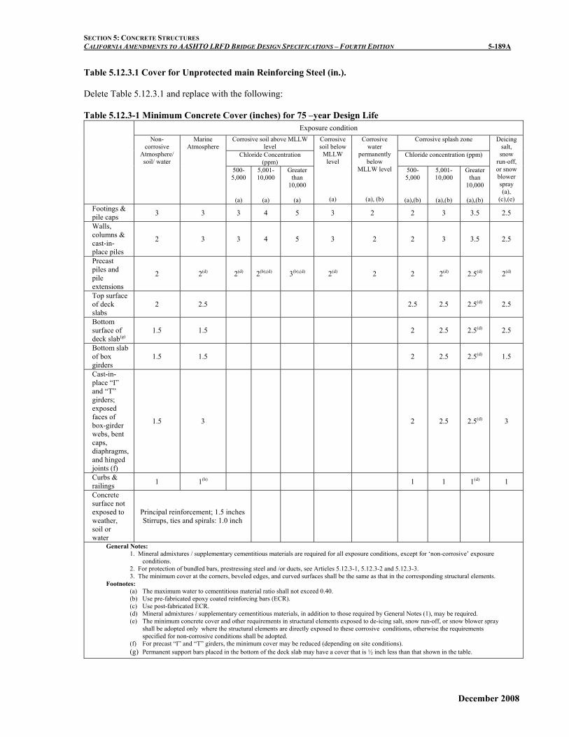
SECTION 5: CONCRETE STRUCTURES CALIFORNIA AMENDMENTS TO AASHTO LRFD BRIDGE DESIGN SPECIFICATIONS – FOURTH EDITION 5-189A Table 5.12.3.1 Cover for Unprotected main Reinforcing Steel (in.). Delete Table 5.12.3.1 and replace with the following: Table 5.12.3-1 Minimum Concrete Cover (inches) for 75 –year Design Life
Exposure condition Corrosive soil above MLLW
level Corrosive splash zone
Chloride Concentration (ppm)
Chloride concentration (ppm)
Non-corrosive
Atmosphere/ soil/ water
Marine Atmosphere
500-5,000
(a)
5,001-10,000
(a)
Greater than
10,000
(a)
Corrosive soil below
MLLW level
(a)
Corrosive water
permanently below
MLLW level
(a), (b)
500-5,000
(a),(b)
5,001-10,000
(a),(b)
Greater than
10,000
(a),(b)
Deicing salt, snow
run-off, or snow blower spray (a),
(c),(e) Footings & pile caps 3 3 3 4 5 3 2 2 3 3.5 2.5
Walls, columns & cast-in-place piles
2 3 3 4 5 3 2 2 3 3.5 2.5
Precast piles and pile extensions
2 2(d) 2(d) 2(b),(d) 3(b),(d) 2(d) 2 2 2(d) 2.5(d) 2(d)
Top surface of deck slabs
2 2.5 2.5 2.5 2.5(d) 2.5
Bottom surface of deck slab(g)
1.5 1.5 2 2.5 2.5(d) 2.5
Bottom slab of box girders
1.5 1.5 2 2.5 2.5(d) 1.5
Cast-in-place “I” and “T” girders; exposed faces of box-girder webs, bent caps, diaphragms, and hinged joints (f)
1.5 3 2 2.5 2.5(d) 3
Curbs & railings 1 1(b) 1 1 1(d) 1
Concrete surface not exposed to weather, soil or water
Principal reinforcement; 1.5 inches Stirrups, ties and spirals: 1.0 inch
General Notes: 1. Mineral admixtures / supplementary cementitious materials are required for all exposure conditions, except for ‘non-corrosive’ exposure
conditions. 2. For protection of bundled bars, prestressing steel and /or ducts, see Articles 5.12.3-1, 5.12.3-2 and 5.12.3-3. 3. The minimum cover at the corners, beveled edges, and curved surfaces shall be the same as that in the corresponding structural elements.
Footnotes: (a) The maximum water to cementitious material ratio shall not exceed 0.40. (b) Use pre-fabricated epoxy coated reinforcing bars (ECR). (c) Use post-fabricated ECR. (d) Mineral admixtures / supplementary cementitious materials, in addition to those required by General Notes (1), may be required. (e) The minimum concrete cover and other requirements in structural elements exposed to de-icing salt, snow run-off, or snow blower spray
shall be adopted only where the structural elements are directly exposed to these corrosive conditions, otherwise the requirements specified for non-corrosive conditions shall be adopted.
(f) For precast “I” and “T” girders, the minimum cover may be reduced (depending on site conditions). (g) Permanent support bars placed in the bottom of the deck slab may have a cover that is ½ inch less than that shown in the table.
December 2008

SECTION 5: CONCRETE STRUCTURES CALIFORNIA AMENDMENTS TO AASHTO LRFD BRIDGE DESIGN SPECIFICATIONS – FOURTH EDITION 5-189B
5.12.3.1 Protection for Bundled Bars For bundled bars, the minimum concrete cover in
non-corrosive atmosphere shall be equal to the equivalent diameter of the bundle, but need not be greater than 2 inches; except for concrete cast against and permanently exposed to non-corrosive soil, where the minimum cover shall be 3 inches. In corrosive environment, the cover shall be the same as that specified in Table 5.12.3-1, except that it shall not be less than the cover specified for bundled bars in non-corrosive environment.
5.12.3.2 Protection for Prestressing Tendons
In corrosive environments, the minimum concrete
cover to prestressing steel not placed within ducts, shall be the same as that specified for reinforcement (Table 5.12.3-1), except that when epoxy-coated reinforcement is required per Table 5.12.3-1, the prestressing steel shall either be epoxy-coated or the minimum concrete cover to the prestressing steel shall be increased by 1.0 inch beyond that specified in Table 5.12.3-1.
Ducts for internal post-tensioned tendons, designed to provide bonded resistance, shall be grouted after stressing.
Other tendons shall be permanently protected against corrosion and the details of protection shall be indicated in the contract documents.
C5.12.3.2
In certain cases, such as the tieing together of
longitudinal precast elements by transverse post-tensioning, the integrity of the structure does not depend on the bonded resistance of the tendons, but rather on the confinement provided by the prestressing elements. The unbonded tendons can be more readily inspected and replaced, one at a time, if so required.
External tendons have been successfully protected by cement grout in polyethylene or metal tubing. Tendons have also been protected by heavy grease or other anticorrosion medium where future replacement is envisioned. Tendon anchorage regions should be protected by encapsulation or other effective means. This is critical in unbonded tendons because any failure of the anchorage can release the entire tendon.
5.12.3.3 Protection for Ducts
The minimum concrete cover for protection of ducts in corrosive environment shall be the same as that specified for reinforcement in Table 5.12.3-1, except that:
(a) the concrete cover over the duct shall not be less than one-half the diameter of the duct; and,
(b) when epoxy-coated reinforcement is required, the minimum concrete cover over the duct shall be increased by 0.50 inches beyond that specified for reinforcement in Table 5.12.3-1, but shall not be less than that specified in (a).
December 2008
SECTION 5: CONCRETE STRUCTURES CALIFORNIA AMENDMENTS TO AASHTO LRFD BRIDGE DESIGN SPECIFICATIONS – FOURTH EDITION 5-189C
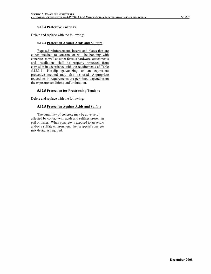
5.12.4 Protective Coatings
Delete and replace with the following:
5.12.4 Protection Against Acids and Sulfates
Exposed reinforcement, inserts and plates that are either attached to concrete or will be bonding with concrete, as well as other ferrous hardware, attachments and installations shall be properly protected from corrosion in accordance with the requirements of Table 5.12.3-1. Hot-dip galvanizing or an equivalent protective method may also be used. Appropriate reductions in requirements are permitted depending on the exposure conditions and/or duration.
5.12.5 Protection for Prestressing Tendons
Delete and replace with the following:
5.12.5 Protection Against Acids and Sulfate
The durability of concrete may be adversely affected by contact with acids and sulfates present in soil or water. When concrete is exposed to an acidic and/or a sulfate environment, then a special concrete mix design is required.
December 2008

SECTION 5: CONCRETE STRUCTURES CALIFORNIA AMENDMENTS TO AASHTO LRFD BRIDGE DESIGN SPECIFICATIONS – FOURTH EDITION 5-189D
This page is intentionally left blank.
December 2008

SECTION 5: CONCRETE STRUCTURES CALIFORNIA AMENDMENTS TO AASHTO LRFD BRIDGE DESIGN SPECIFICATIONS – FOURTH EDITION 5-215A
5.14.1.4.1 General Revise the 1st Paragraph as follows:
The provisions of this Article shall apply at the
service and strength limit states as applicable. Article 5.14.1.4 need not be applied to design of multi-span bridges composed of precast girders with continuity diaphragms at bent caps.
C5.14.1.4.1
Insert before 1st Paragraph as follows:
Article 5.14.1.4 provides design requirements mainly for multi-span bridges composed of precast girders made continuous with a drop cap bent system. The research to develop these requirements did not consider an inverted T-cap bent system. Caltrans provides a continuous diaphragm by threading dowels through the dapped end of the precast girders prior to pouring concrete between the girder ends. Shear stirrups extend up into the deck, with especially close stirrup spacing at the girder ends. Positive moment is presumed to be transferred into the bent cap. Currently, Caltrans is sponsoring a research study to study and develop connection details between the inverted T-cap bent and precast girders. The requirements of Article 5.14.1.4 may be used as the guidance for design of multi-span bridges composed of precast girders made continuous with the drop cap bent system.
December 2008

SECTION 5: CONCRETE STRUCTURES CALIFORNIA AMENDMENTS TO AASHTO LRFD BRIDGE DESIGN SPECIFICATIONS – FOURTH EDITION 5-215B
This page is intentionally left blank.
December 2008