Embed Size (px)
Citation preview

1311-(4) V1.1 6/0433
Section 4.0
RiggerInformation
1311-(4) V1.1 6/0434
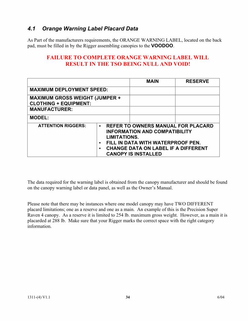
4.1 Orange Warning Label Placard Data
As Part of the manufacturers requirements, the ORANGE WARNING LABEL, located on the backpad, must be filled in by the Rigger assembling canopies to the VOODOO.
FAILURE TO COMPLETE ORANGE WARNING LABEL WILLRESULT IN THE TSO BEING NULL AND VOID!
MAIN RESERVE
MAXIMUM DEPLOYMENT SPEED:
MAXIMUM GROSS WEIGHT (JUMPER +CLOTHING + EQUIPMENT:MANUFACTURER:
MODEL:
ATTENTION RIGGERS: • REFER TO OWNERS MANUAL FOR PLACARDINFORMATION AND COMPATIBILITYLIMITATIONS.
• FILL IN DATA WITH WATERPROOF PEN.• CHANGE DATA ON LABEL IF A DIFFERENT
CANOPY IS INSTALLED
The data required for the warning label is obtained from the canopy manufacturer and should be foundon the canopy warning label or data panel, as well as the Owner’s Manual.
Please note that there may be instances where one model canopy may have TWO DIFFERENTplacard limitations; one as a reserve and one as a main. An example of this is the Precision SuperRaven 4 canopy. As a reserve it is limited to 254 lb. maximum gross weight. However, as a main it isplacarded at 288 lb. Make sure that your Rigger marks the correct space with the right categoryinformation.

1311-(4) V1.1 6/0435
4.2 Parachute Assembly Inspection Form
Parachute Assembly Inspection Form! Note: Count all Tools Before Starting Assembly Qty:
Manufacturer:
Model:
Harness and Date of manufacture:
Container Serial no:
Initial After Each Item If No Discrepancies Are Found Initials1. Main lift web2. Chest and leg straps3. Harness hardware and Flex-rings4. 3-ring release5. Pilot chute pocket6. Reserve ripcord, handle pocket, cable housing7. Cutaway handle, attachment point, cable housing and channels8. Container flaps and grommets9. Closing loop length and condition (main and reserve)10. Comments:
Manufacturer:
Model:
Main Canopy and Date of manufacture:
Pilot chute Serial no.:
Initial After Each Item If No Discrepancies Are Found Initials
1. Risers and 3-Ring2. Connector links and slider bumpers3. Slider grommets, tapes, fabric4. A-lines and attachment points5. B-lines and attachment points6. C-lines and attachment points7. D-lines and attachment points8. Steering lines and toggles9. Canopy cells and cross-ports10. Slider stops ( on canopy )11. Bridle line, d-bag stop, pin12. Pilot chute and handle or pud13. Deployment bag14. Comments:
A
B

1311-(4) V1.1 6/0436
Manufacturer:
Model:
Square Reserve Canopy Date of manufacture:
and Pilot chute Serial no:
Initial After Each Item If No Discrepancies Are Found Initials1. Risers2. Connector links3. Sliders & Grommets4. A-lines and attachment points5. B-lines and attachment points6. C-lines and attachment points7. D-lines and attachment points8. Steering lines and toggles9. Canopy cells and cross ports10. Slider stops (on canopy)11. Deployment bag and safety stow12.. Bridle line13. Pilot chute14. Packing card and information15. Comments:
Assembly ofSquare Reserve CanopyInitial After Each Item If No Discrepancies Are Found Initials
1. Inspection of canopy and Container completed (parts A & C )2. Line Continuity correct including steering lines thru slider grommets3. Slider on correctly4. Rapide™ links tightened or Slinks™ assembled correctly.5. Steering lines tied to toggles on mark6. Steering line length equal to each other7. Safety stow on deployment bag installed8. Packing data card filled out9. Packed according to manufacturers instructions10. Reserve pin sealed11. Fill out warning label12. Comments:
C
D

1311-(4) V1.1 6/0437
Assembly ofMain Canopy to ContainerInitial After Each Item If No Discrepancies Are Found Initials
1. Inspection of canopy and Container completed (parts A & B )2. Line continuity correct including steering lines thru slider grommets.3. Slider on correctly4. Release handle cables are proper lengths5. Rapide™ links tightened or Slinks™ assembled correctly6. Steering lines tied to toggles on mark7. Steering line length equal to each other8. D-bag, bridle and pilot chute are attached properly9. Fill out warning label10. Comments:
! Note: Count all tools after assembly and packing is
completed to ensure that none were left in the canopy or
container.
Qty:
Signature of Rigger(s) Inspection
Signature: Date:
Print Name and Seal Symbol:
Signature: Date:
Print name and Seal Symbol:
General Comments:
E
1311-(4) V1.1 6/0438
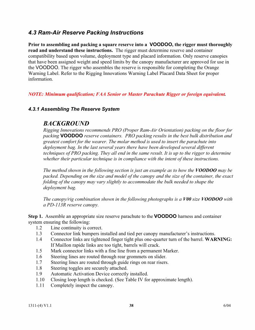
4.3 Ram-Air Reserve Packing Instructions
Prior to assembling and packing a square reserve into a VOODOO, the rigger must thoroughlyread and understand these instructions. The rigger must determine reserve and containercompatibility based upon volume, deployment type and placard information. Only reserve canopiesthat have been assigned weight and speed limits by the canopy manufacturer are approved for use inthe VOODOO. The rigger who assembles the reserve is responsible for completing the OrangeWarning Label. Refer to the Rigging Innovations Warning Label Placard Data Sheet for properinformation.
NOTE: Minimum qualification; FAA Senior or Master Parachute Rigger or foreign equivalent.
4.3.1 Assembling The Reserve System
BACKGROUNDRigging Innovations recommends PRO (Proper Ram-Air Orientation) packing on the floor forpacking VOODOO reserve containers. PRO packing results in the best bulk distribution andgreatest comfort for the wearer. The molar method is used to insert the parachute intodeployment bag. In the last several years there have been developed several differenttechniques of PRO packing. They all end in the same result. It is up to the rigger to determinewhether their particular technique is in compliance with the intent of these instructions.
The method shown in the following section is just an example as to how the VOODOO may bepacked. Depending on the size and model of the canopy and the size of the container, the exactfolding of the canopy may vary slightly to accommodate the bulk needed to shape thedeployment bag.
The canopy/rig combination shown in the following photographs is a V00 size VOODOO witha PD-113R reserve canopy.
Step 1. Assemble an appropriate size reserve parachute to the VOODOO harness and containersystem ensuring the following:
1.2 Line continuity is correct.1.3 Connector link bumpers installed and tied per canopy manufacturer’s instructions.1.4 Connector links are tightened finger tight plus one-quarter turn of the barrel. WARNING:
If Maillon rapide links are too tight, barrels will crack.1.5 Mark connector links with a fine line from a permanent Marker.1.6 Steering lines are routed through rear grommets on slider.1.7 Steering lines are routed through guide rings on rear risers.1.8 Steering toggles are securely attached.1.9 Automatic Activation Device correctly installed.1.10 Closing loop length is checked. (See Table IV for approximate length).1.11 Completely inspect the canopy.

1311-(4) V1.1 6/0439
NOTE: Rigging Innovations has tested and evaluated the Slink™ brand of Soft Link manufactured byPerformance Designs Inc. RI HIGHLY RECOMMENDS the use of this product in conjunction withthe VOODOO harness and container system. The use of this product results in a stronger assemblythat is easier to pack and more comfortable to the wearer as it eliminates the metal links and thecorresponding slider bumper bulk.
4.3.2 Table IV -Approximate Closing Loop Lengths
NOTE: The loop length recommended in this chart is an approximation based on packingexperience in our facility. Variables such as canopy size, temperature, humidity, and packingtechnique will affect the best loop length. In addition, these lengths include the additionallength necessary for the Cypres™ cutter.
IT IS THE RIGGER’S RESPONSIBILITY TO ENSURE THE RIPCORD PULLFORCE DOES NOT EXCEED 22 Lb. (10 Kg.).
The loop length is measured from the washer to end of the loop.
TABLE IV
CONTAINER SIZE LENGTH
V000 4.50”/114mm
V00 4.75”/120mm
V0 5.12”/130mm
V1 5.12”/130mm
V2 5.25”/133mm
V3 5.50/138mm
V4 5.50/138mm
NOTE: Only CYPRES™ type closing loops are approved for use with “loop-cutter” AutomaticActivation Devices. Thicker loops made from other materials are dangerous because they mayslow pack opening and reserve deployment.
4.3.3 Cypres™ AAD Reserve Installation
Only modern, electronic “loop cutter” type AADs have been tested and approved for use with theVOODOO system. The most popular brand of loop cutter AAD is the CYPRES™ manufactured byAirtec GmbH, in Germany. The very small container volumes and closing configuration ofVOODOO prevent the use of older style AADs.

1311-(4) V1.1 6/0440
The VOODOO comes “CYPRES™-ready” from the factory with all the pockets, channels and otherparts necessary for direct installation of the AAD without further modification.
The following instructions tell the rigger how to install a CYPRES™ in the VOODOO. However, it isimportant that the rigger also have a current copy of the CYPRES™ Rigger’s Guide to familiarize himor her with the total CYPRES™ concept. Also, the rigger should have a CYPRES™ Rigger’s Kitcontaining several useful tools when installing a CYPRES™.
Step 1. The reserve locking loop supplied with the CYPRES™ MUST be used. Special discs suppliedwith CYPRES™ must also be used to make knots for locking loop.Step 2. Adjust locking loop to appropriate length in accordance with Table IV. Install locking loopinto container.Step 3. Install CYPRES™ processing unit into spandex pocket on divider wall at bottom of reservecontainer. (Fig 4-1)Step 4. Thread cutter unit up through grommet and then through spandex channel on inside of rightreserve side flap. Push cutter through elastic keeper next to grommet and align hole in cutter withgrommet. (Fig 4-2)
Fig 4-1 Fig 4-2
Step 5. Carefully coil excess cutter cable under Velcro closure flap located on right end ofCYPRES™ installation pocket. DO NOT bend or kink excess cable. (Fig 4-3)Step 6. Carefully push control unit through channel on bottom of reserve container from bottom totop. (Fig 4–4)
Fig 4-3 Fig 4-4

1311-(4) V1.1 6/0441
Step 7. Gently slide control unit out through the upper right corner of reserve pack tray (Fig 4-5) andinto the spandex pocket at the yoke area. Double check that control button, display and red light arevisible in pocket window. (Fig 4-6)Step 8. Pull slack in control cable back down into pack tray, leaving about 1/2” (1 cm) slack wherecable curves into the container. Coil excess cable neatly without kinks or sharp bends into the tunnelpocket on pack tray at the right side of the stiffener plate. (Fig 4-7)
Fig 4-5 Fig 4-6 Fig 4-7
4.3.4 Folding the Reserve Parachute
Before you start! Check for recent updates or R.I. Service Bulletins
Telephone: 520.466.2655
FAX: 520.466.2656
Website: www.rigginginnovations.com
1311-(4) V1.1 6/0442
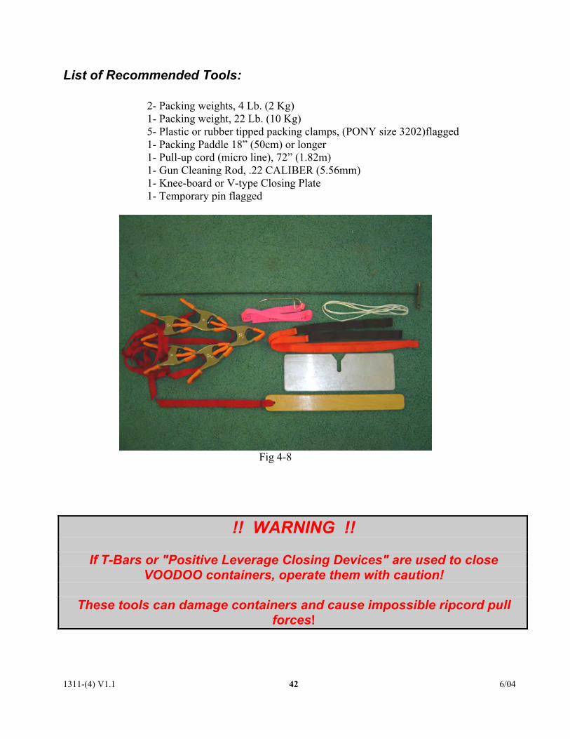
List of Recommended Tools:
2- Packing weights, 4 Lb. (2 Kg)1- Packing weight, 22 Lb. (10 Kg)5- Plastic or rubber tipped packing clamps, (PONY size 3202)flagged1- Packing Paddle 18” (50cm) or longer1- Pull-up cord (micro line), 72” (1.82m)1- Gun Cleaning Rod, .22 CALIBER (5.56mm)1- Knee-board or V-type Closing Plate1- Temporary pin flagged
Fig 4-8
!! WARNING !!
If T-Bars or "Positive Leverage Closing Devices" are used to closeVOODOO containers, operate them with caution!
These tools can damage containers and cause impossible ripcord pullforces!

1311-(4) V1.1 6/0443
Reserve Parachute Pro Packing Instructions
1-Basic layout and setting up packing clampsAnchor the risers at the connectorlinks including the steering lines.(Fig.4-9)
Place a 22# packing weight on topof it.
Fig 4-9
Pull the slider down to the connectorlinks. Make sure the tapes faceupwards towards the canopy.(Fig 4-10)
Fig 4-10
Lay the canopy on its right side.(Note: A mirror image of the layoutis permissible).
Flake the canopy so that the topseams are even. Place a clamp on thetop of the canopy in line with eachline attachment point as in the photo.(Fig 4-11)
Fig 4-11

1311-(4) V1.1 6/0444
Note: The step of shaping the canopy stack and the molar ears is very much subject toindividual technique. The shape of the VOODOO reserve container and bag is morerounded at the top as opposed to other more tapered designs such as the Talon 2. Thisis in keeping with the aerodynamic convex curve of the VOODOO profile. While notsignificantly different from other designs, the rigger should do a couple of practice packjobs on their first VOODOO container to get the feel for the balance and bulkdistribution of a particular VOODOO /canopy combination. The ears of the molar bagare designed to accept more bulk to create the “VOODOO” curve.
2-Stacking and folding the reserve canopyThe finished configuration for the canopy stack should look like Fig 4-12 when completed.
Fig 4-12
1311-(4) V1.1 6/0445
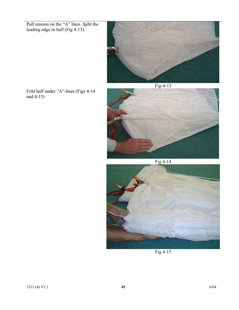
Pull tension on the “A” lines. Split theleading edge in half (Fig 4-13).
Fig-4-13
Fig 4-14
Fold half under ”A”-lines (Figs 4-14and 4-15)
Fig 4-15
1311-(4) V1.1 6/0446
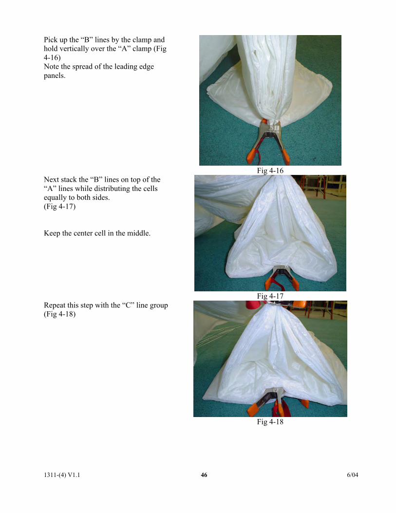
Pick up the “B” lines by the clamp andhold vertically over the “A” clamp (Fig4-16)Note the spread of the leading edgepanels.
Fig 4-16Next stack the “B” lines on top of the“A” lines while distributing the cellsequally to both sides.(Fig 4-17)
Keep the center cell in the middle.
Fig 4-17Repeat this step with the “C” line group(Fig 4-18)
Fig 4-18
1311-(4) V1.1 6/0447
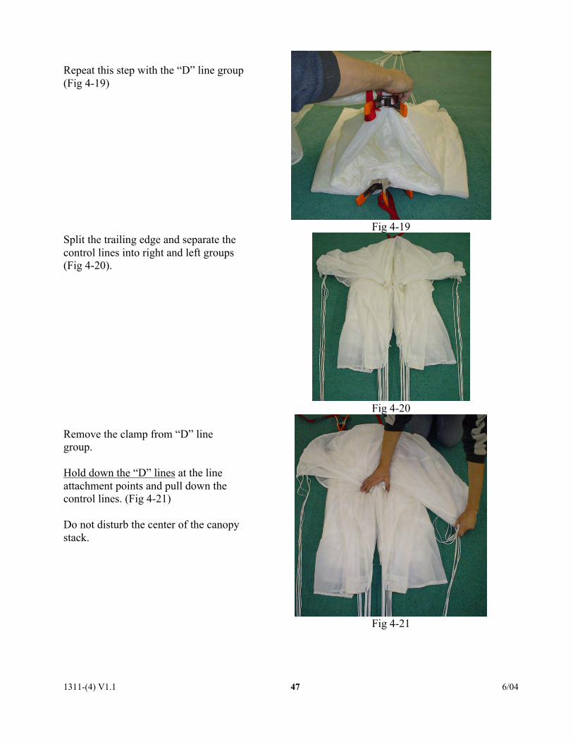
Repeat this step with the “D” line group(Fig 4-19)
Fig 4-19Split the trailing edge and separate thecontrol lines into right and left groups(Fig 4-20).
Fig 4-20
Remove the clamp from “D” linegroup.
Hold down the “D” lines at the lineattachment points and pull down thecontrol lines. (Fig 4-21)
Do not disturb the center of the canopystack.
Fig 4-21
1311-(4) V1.1 6/0448
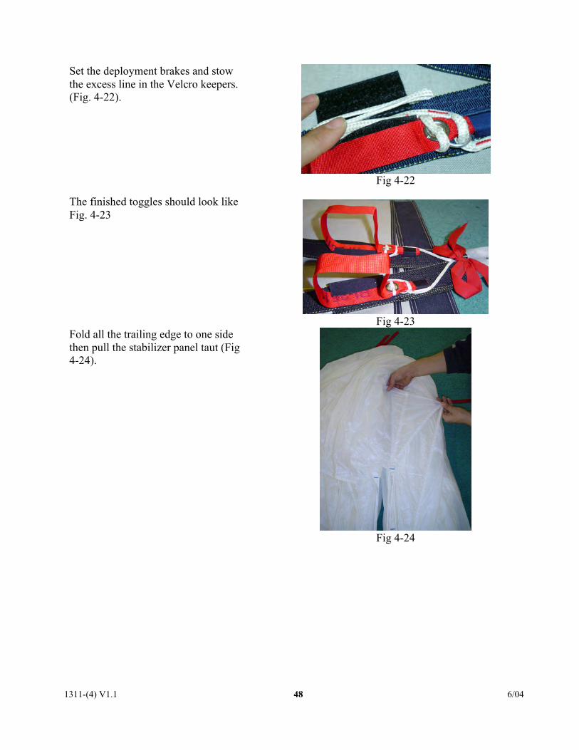
Set the deployment brakes and stowthe excess line in the Velcro keepers.(Fig. 4-22).
The finished toggles should look likeFig. 4-23
Fig 4-22
Fig 4-23Fold all the trailing edge to one sidethen pull the stabilizer panel taut (Fig4-24).
Fig 4-24
1311-(4) V1.1 6/0449
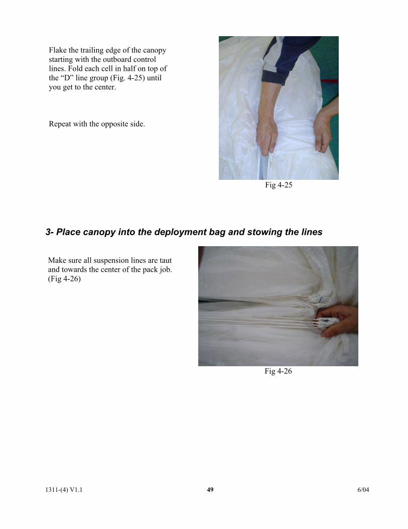
Flake the trailing edge of the canopystarting with the outboard controllines. Fold each cell in half on top ofthe “D” line group (Fig. 4-25) untilyou get to the center.
Repeat with the opposite side.
Fig 4-25
3- Place canopy into the deployment bag and stowing the lines
Make sure all suspension lines are tautand towards the center of the pack job.(Fig 4-26)
Fig 4-26

1311-(4) V1.1 6/0450
Pull slider up to the slider stops.
Fold the center of the trailing edgeback to expose the center of the “windchannel”. (Fig. 4-27)
Fig 4-27
Create an “S” fold in the stack. (Fig. 4-28)
Position a packing paddle at a third ofthe way up from the bottom of thecanopy length on top of the stack.Place a gun-cleaning rod at half thedistance between the bottom and thepacking paddle under the stack. (Fig.4-29)
Pull the rod up and move the canopywith paddle towards container.
Fig 4-28
Fig 4-29

1311-(4) V1.1 6/0451
Pull the top center cell panel down tothe bottom of the stack.
Wrap the center cell around the foldedcanopy with the left and right abouthalfway to the center, then secure withclamps, starting at the bottom (Fig. 4-30 ).
The width of the folded canopy needsto be the width of the freebag plus 2 in(5cm).
Fig 4-30
Continue to wrap the center cell around thecanopy stack and secure with additionalclamps (Fig. 4-31).
Fig 4-31 Lift the base of the folded canopy and slidethe reserve bag underneath. The grommetsin the tongue of the bag should be even withthe bottom of the stack (Fig. 4-32).
Fig 4-32
1311-(4) V1.1 6/0452
Fig 4-33
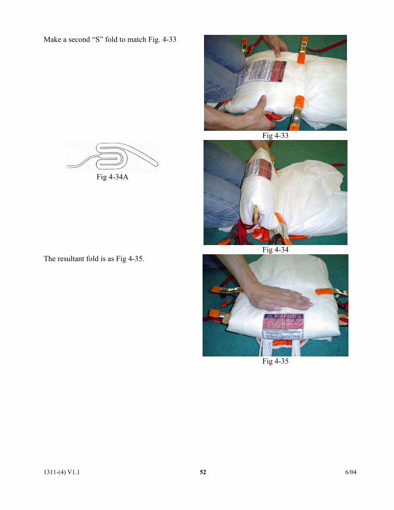
Make a second “S” fold to match Fig. 4-33
Fig 4-34A
Fig 4-34The resultant fold is as Fig 4-35.
Fig 4-35
1311-(4) V1.1 6/0453
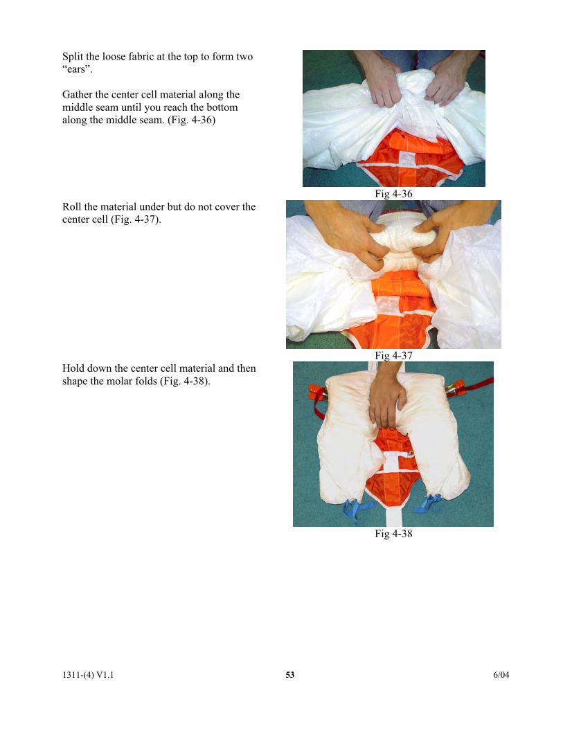
Split the loose fabric at the top to form two“ears”.
Gather the center cell material along themiddle seam until you reach the bottomalong the middle seam. (Fig. 4-36)
Fig 4-36Roll the material under but do not cover thecenter cell (Fig. 4-37).
Fig 4-37Hold down the center cell material and thenshape the molar folds (Fig. 4-38).
Fig 4-38
1311-(4) V1.1 6/0454
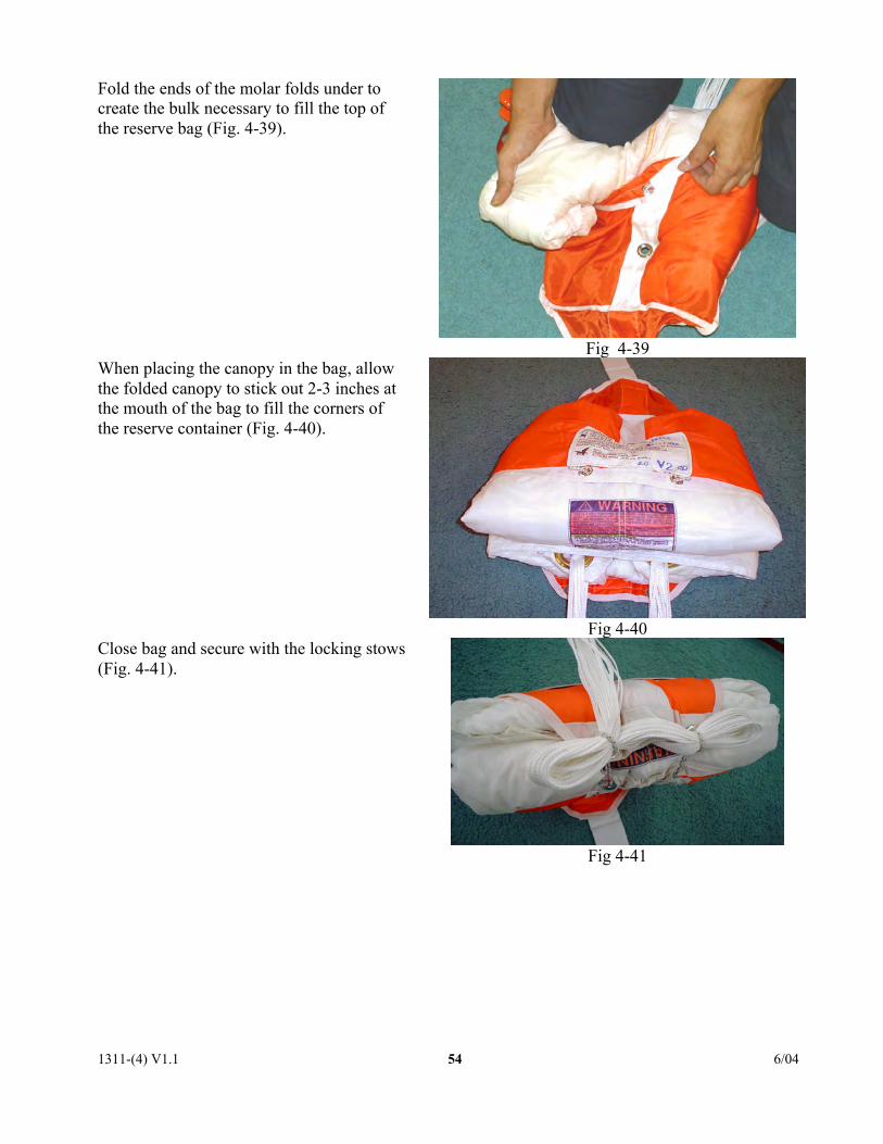
Fold the ends of the molar folds under tocreate the bulk necessary to fill the top ofthe reserve bag (Fig. 4-39).
Fig 4-39When placing the canopy in the bag, allowthe folded canopy to stick out 2-3 inches atthe mouth of the bag to fill the corners ofthe reserve container (Fig. 4-40).
Fig 4-40Close bag and secure with the locking stows(Fig. 4-41).
Fig 4-41
1311-(4) V1.1 6/0455
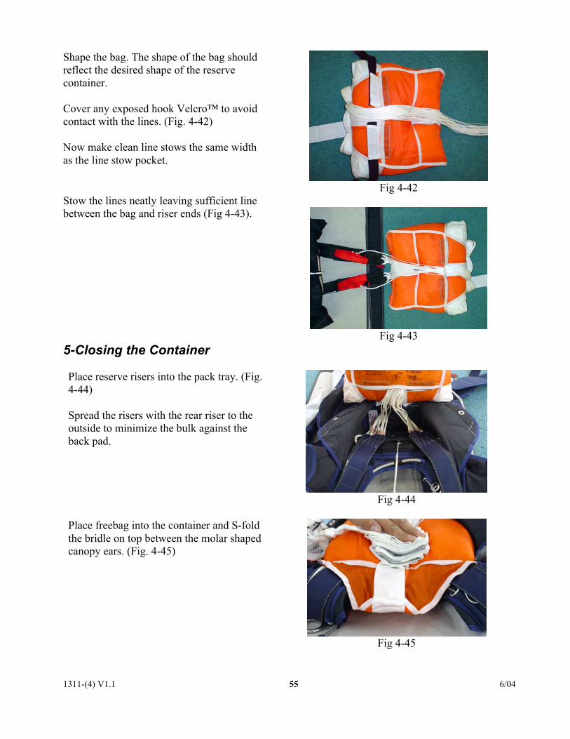
Shape the bag. The shape of the bag shouldreflect the desired shape of the reservecontainer.
Cover any exposed hook Velcro™ to avoidcontact with the lines. (Fig. 4-42)
Now make clean line stows the same widthas the line stow pocket.
Fig 4-42Stow the lines neatly leaving sufficient linebetween the bag and riser ends (Fig 4-43).
Fig 4-435-Closing the Container
Place reserve risers into the pack tray. (Fig.4-44)
Spread the risers with the rear riser to theoutside to minimize the bulk against theback pad.
Fig 4-44
Place freebag into the container and S-foldthe bridle on top between the molar shapedcanopy ears. (Fig. 4-45)
Fig 4-45
1311-(4) V1.1 6/0456
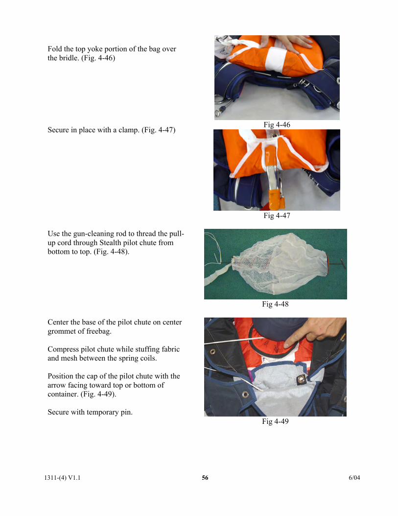
Fold the top yoke portion of the bag overthe bridle. (Fig. 4-46)
Secure in place with a clamp. (Fig. 4-47)Fig 4-46
Fig 4-47
Use the gun-cleaning rod to thread the pull-up cord through Stealth pilot chute frombottom to top. (Fig. 4-48).
Fig 4-48
Center the base of the pilot chute on centergrommet of freebag.
Compress pilot chute while stuffing fabricand mesh between the spring coils.
Position the cap of the pilot chute with thearrow facing toward top or bottom ofcontainer. (Fig. 4-49).
Secure with temporary pin.Fig 4-49

1311-(4) V1.1 6/0457
WARNING! Do not leave fabric outside of spring coils as a coil lock could occur and pilotchute launch may be inhibited!
If an AAD such as a Cypres™ is installed,route the pull-up cord through the cutterfirst then through the right (#1)side flapgrommet. (Fig. 4-50)
Fig 4-50
Next thread the left (#2) side flap grommet.Simultaneously close the side flaps (Fig. 4-51). Secure with temporary pin.
Fig 4-51
Close bottom flap #3 and secure withtemporary pin. (Fig. 4-52).
Note: At this point, you should only beable to pull 1/4" – 1/2" of loop through thefirst three flaps. If you can pull more, theloop is too long. Open container andshorten loop.
Fig 4-52
1311-(4) V1.1 6/0458
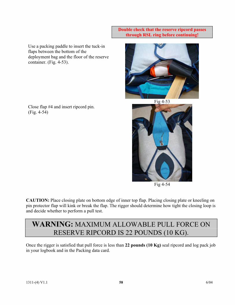
Double check that the reserve ripcord passesthrough RSL ring before continuing!
Use a packing paddle to insert the tuck-inflaps between the bottom of thedeployment bag and the floor of the reservecontainer. (Fig. 4-53).
Fig 4-53Close flap #4 and insert ripcord pin.(Fig. 4-54)
Fig 4-54
CAUTION: Place closing plate on bottom edge of inner top flap. Placing closing plate or kneeling onpin protector flap will kink or break the flap. The rigger should determine how tight the closing loop isand decide whether to perform a pull test.
WARNING: MAXIMUM ALLOWABLE PULL FORCE ONRESERVE RIPCORD IS 22 POUNDS (10 KG).
Once the rigger is satisfied that pull force is less than 22 pounds (10 Kg) seal ripcord and log pack jobin your logbook and in the Packing data card.

1311-(4) V1.1 6/0459
Place the data card in the data card pocket locatedbehind the top of the orange warning label. (Fig4-55).
Fig 4-55
COUNT YOUR TOOLS!
2- Packing weights, 4 Lb. (2 Kg)1- Packing weight, 22 Lb. (10 Kg)5- Plastic or rubber tipped packing clamps, (PONY size 3202)flagged1- Packing Paddle 18” (50cm) or longer1- Pull-up cord (microcline), 72” (1.82m)1- Gun Cleaning Rod, .22 CALIBER (5.56mm)1- Kneeboard or V-type Closing Plate1- Temporary pin flagged
COMPLETE PLACARD DATA ON ORANGE WARNING LABEL.
FAILURE TO COMPLETE ORANGE WARNING LABEL WILL
VOID THE TSO.

1311-(4) V1.1 6/0460
RIGGING INNOVATIONS INC.
P O BOX 86ELOY AZ 85231, USA
TEL 520.466.2655FAX 520.466.2656