Embed Size (px)
DESCRIPTION
Power take off
Citation preview
Trakker Euro 4/5 POWER TAKE-OFFS 4-1
Print 603 93 731 Base - July 2007
SECTION 4 Power take offs
Page
4.1 General Specifications 4-3
4.2 Power Take-off from Gearbox 4-5
4.3 Power Take-off from Transfer Box 4-8
4.4 Power Take-off from Drive line 4-9
4.5 Power Take-off from Engine 4-104.5.1 Torque power take off from the front of the engine 4-104.5.2 Power take off from the rear of the engine 4-11
4.6 PTO management 4-174.6.1 General Specifications 4-184.6.2 PTO 0 mode (run mode) 4-184.6.3 Configurable PTO 1,2, 3 modes 4-194.6.3.1
Changing the torque curve, maximum rpm and the overrun regulator curve gradient 4-21
4.6.4 Intermediate rpm regulator 4-234.6.5 Standard configurations 4-244.6.6
Specific indications: correlation between the VCM configuration and the installed power take offs 4-25
4.6.7 Engaging the power take off 4-254.6.8 With Allison Gearbox 4-254.6.9 Use of the power take-off with vehicle in motion 4-25
4.7 EM (Expansion Module) 4-284.7.1 Connections 4-294.7.2 PTO activation/deactivation conditions: 4-304.7.3 No PTO installed or provisions for PTO: 4-304.7.4 PTO Multipower 4-304.7.5 PTO manual gearbox with electric engagement 4-314.7.6 PTO FOCSA 4-32
Index
Base - July 2007 Print 603 93 731
4-2 POWER TAKE-OFFS TRAKKER EURO 4/5
Page
4.7.7 Engine PTO 4-324.7.8 PTO Eurotronic 2 transmission 4-334.7.9 PTO TRANSFER BOX 4-33

Base - July 2007 Print 603 93 731
Index
Base - July 2007 Print 603 93 731
4-4 POWER TAKE-OFFS Trakker Euro 4/5
4.1 General Specifications
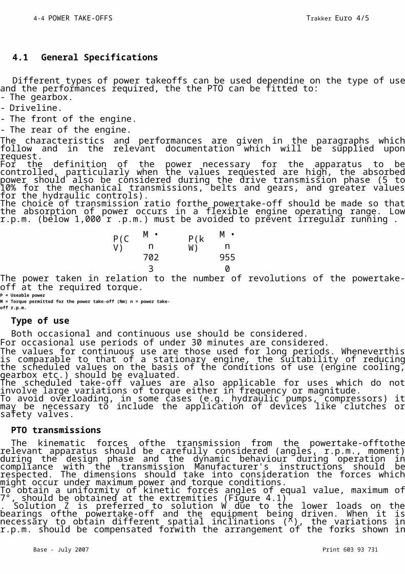
Different types of power takeoffs can be used dependine on the type of use and the performances required, the the PTO can be fitted to:- The gearbox.- Driveline.- The front of the engine.- The rear of the engine.The characteristics and performances are given in the paragraphs which follow and in the relevant documentation which will be supplied upon request.For the definition of the power necessary for the apparatus to be controlled, particularly when the values requested are high, the absorbed power should also be considered during the drive transmission phase (5 to 10% for the mechanical transmissions, belts and gears, and greater values for the hydraulic controls).The choice of transmission ratio forthe powertake-off should be made so that the absorption of power occurs in a flexible engine operating range. Low r.p.m. (below 1,000 r .p.m.) must be avoided to prevent irregular running .
The power taken in relation to the number of revolutions of the powertake-off at the required torque.P = Useable powerM = Torque permitted for the power take-off (Nm) n = power take-off r.p.m.
Type of use
Both occasional and continuous use should be considered.For occasional use periods of under 30 minutes are considered.The values for continuous use are those used for long periods. Wheneverthis is comparable to that of a stationary engine, the suitability of reducing the scheduled values on the basis of the conditions of use (engine cooling, gearbox etc.) should be evaluated.The scheduled take-off values are also applicable for uses which do not involve large variations of torque either in frequency or magnitude.To avoid overloading, in some cases (e.g. hydraulic pumps, compressors) it may be necessary to include the application of devices like clutches or safety valves.
PTO transmissions
The kinematic forces ofthe transmission from the powertake-offtothe relevant apparatus should be carefully considered (angles, r.p.m., moment) during the design phase and the dynamic behaviour during operation in compliance with the transmission Manufacturer's instructions should be respected. The dimensions should take into consideration the forces which might occur under maximum power and torque conditions.To obtain a uniformity of kinetic forces angles of equal value, maximum of 7°, should be obtained at the extremities (Figure 4.1). Solution Z is preferred to solution W due to the lower loads on the bearings ofthe powertake-off and the equipment being driven. When it is necessary to obtain different spatial inclinations (^), the variations in r.p.m. should be compensated forwith the arrangement of the forks shown in Figure 4.2.For transmissions employing multiple sections, the instructions given at point 2.8.2 should be followed.
P(CV)
M • n
7023
P(kW)
M • n
9550
Print 603 93 731 Base - July 2007
Trakker Euro 4/5 POWER TAKE-OFFS 4-5
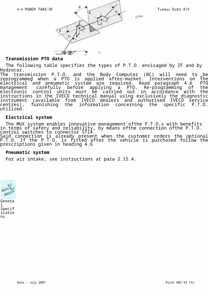
Transmission PTO data
The following table specifies the types of P.T.O. envisaged by ZF and by Hydrocar.The transmission P.T.O. and the Body Computer (BC) will need to be reprogrammed when a PTO is applied after-market. Interventions on the electrical and pneumatic system are required. Read paragraph 4.6 ”PTO management” carefully before applying a PTO. Re-programming of the electronic control units must be carried out in accordance with the instructions in the IVECO technical manual using exclusively the diagnostic instrument (available from IVECO dealers and authorised IVECO service centres), furnishing the information concerning the specific P.T.O. utilized.
Electrical system
The MUX system enables innovative management ofthe P.T.O.s with benefits in terms of safety and reliability, by means ofthe connection ofthe P.T.O. control switches to connector STI4.Said connection is already present when the customer orders the optional P.T.O. If the P.T.O. is fitted after the vehicle is purchased follow the prescriptions given in heading 4.6
Pneumatic system
For air intake, see instructions at para 2.15.4.
I 91523 I
General Specifications
Base - July 2007 Print 603 93 731
4-6 POWER TAKE-OFFS Trakker Euro 4/5
4.2 Power Take-off from Gearbox
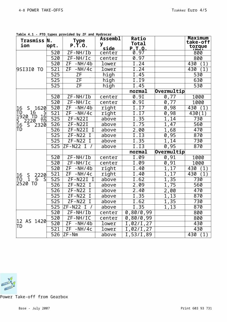
Depending on the type of gearbox power can be taken from the layshaft through the flange or spline located on the rear, side or lower part of the gearbox.The technical characteristics necessary are given in the documentation supplied upon request for the various gearboxes.The types of powertake-off and the torque values obtained with the ratio between the number of output revolutions and engine r.p.m. are shown in Table 4.1.The values refer to the conditions indicated in the table.Higher values for occasional use must be agreed upon as each occasion arises depending on the type of use.Check the vehicle to ascertain whether it is possible to fit a powertake-off suitable to its size.The powertake-off applied to the gearbox must only be used when the vehicle is stationary and must be engaged and disengaged when the clutch is disengaged to avoid excessive stress on the synchronisers during gear change. For special situations when the powertake-off is used and the vehicle is moving the gear must not be changed.For gearboxes equipped with a torque converter, the same powertake- offs used for normal gearboxes are, as a rule, used. It should be carefully noted that, when the engine r.p.m. is below 60% of the max. value the converter will be in the phase of hydraulic r.p.m.; in this phase, depending on the absorbed power, the r.p.m. of the power take-off is subject to oscillation despite the fact that the engine r.p.m. is constant.
Direct Application of Pumps
When the application of pumps of other equipment (e.g. fortippers or cranes) is carried out directly from the powertake-off, without the use of intermediate shafts and after checking that the size of the pump permits margins of safety with chassis and engine unit (cross member, transmission shaft etc.), the static and dynamic torques exerted by the mass of the pump and by the power take-off should be checked for compatibility with the resistance of the walls of the gearbox. By way of an example, the moment due to the additional masses must not have values of over 3% approx. of the maximum engine torque.In cases where the gearbox is applied in a single unit with the engine, the value of the additional masses must be verified with regard to the inertial effects in orderto avoid the induction of resonance conditions in the engine unit within the field of operational engine r.p.m.
When fitting power take-offs the torque values shown in Table 4.1 must not be exceeded.Transmission oil temperature must not exceed 120°C during prolonged use. Coolant temperature must not exceed 100°C. Not all types of powertake-off available on the market are suitable for continuous use.
When in use the specifications (working periods, pauses etc.) specific to the power take-off in question should be respected.
Power Take-off from Gearbox
Print 603 93 731 Base - July 2007
Trakker Euro 4/5 POWER TAKE-OFFS 4-7
Power Take-off from Gearbox
Table 4.1 - PTO types provided by ZF and Hydrocar
Trasmission
N. opt.
Type P.T.O.
Assemblyside
RatioTotal P.T.O.
Maximum take-
off torque
9SI3I0 TO
5202
ZF-NH/Ib center 0.97 8005205
ZF-NH/Ic center 0.97 8005209
ZF -NH/4b lower I.24 430 (1)5210
ZF -NH/4c lower I.24 430 (1)5258
ZF -NI09/I0b high I.45 5305255
ZF -NI09/I0c high I.I9 6305259
ZF -NI09/I0c high I.45 530
16 S 1620 TD 16 S 1920 TD 16 S 2220 TD 16 S 2320 TD
normal Overmultiplied520
2ZF-NH/Ib center 0.9I 0,77 1000
5205
ZF-NH/Ic center 0.9I 0,77 10005209
ZF -NH/4b right I.I7 0,98 430 (1)5210
ZF -NH/4c right I.I7 0,98 430(1)5258
ZF-N22I 10/B
above I.35 1,14 7305260
ZF-N22I 10/B
above I.75 1,47 5605264
ZF-N22I I 0/B
above 2.00 1,68 4705255
ZF-N22 I I 0/C
above I.I3 0,95 8705259
ZF-N22 I I 0/C
above I.35 1,14 7305255
ZF-N22 I / I 0C-PL
above I.I3 0,95 870
16 S 2220 TO 1 6 S 2520 TO
normal Overmultiplied520
2ZF-NH/Ib center I.09 0,91 1000
5205
ZF-NH/Ic center I.09 0,91 10005209
ZF -NH/4b right I.40 1,17 430 (1)5210
ZF -NH/4c right I.40 1,17 430 (1)5258
ZF-N22I I 0/B
above I.62 1,35 7305260
ZF-N22 I I 0/B
above 2.09 1,75 5605264
ZF-N22 I I 0/B
above 2.40 2,00 4705255
ZF-N22 I I 0/C
above I.35 1,13 8705259
ZF-N22 I I 0/C
above I.62 1,35 7305255
ZF-N22 I / I 0C-PL
above I.35 1,13 870
12 AS 1420 TD
5202
ZF-NH/Ib center 0,80/0,99 8005205
ZF-NH/IC center 0,80/0,99 8005209
ZF -NH/4b lower I,02/I,27 4305210
ZF -NH/4c lower I,02/I,27 4305260
ZF-Nm AS/I0 b
above I,53/I,89 430 (1)
Base - July 2007 Print 603 93 731
4-8 POWER TAKE-OFFS Trakker Euro 4/5
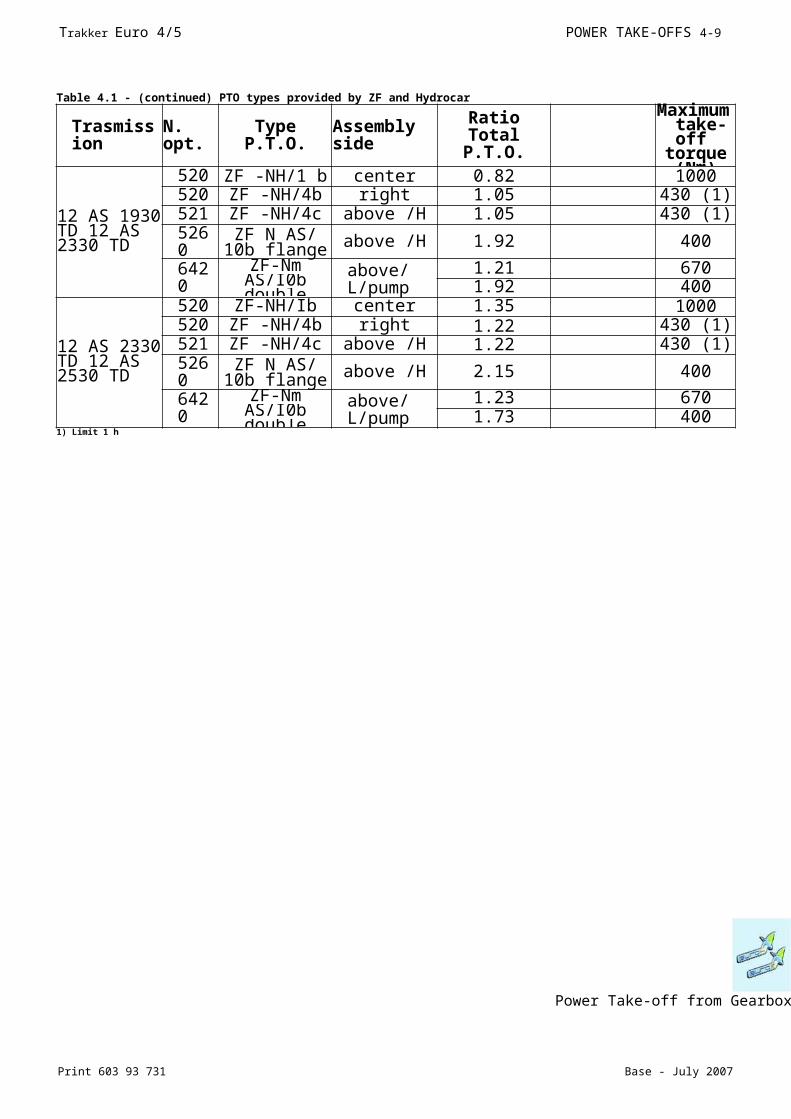
Power Take-off from Gearbox
Table 4.1 - (continued) PTO types provided by ZF and Hydrocar
Trasmission
N. opt.
Type P.T.O.
Assembly side
RatioTotal P.T.O.
Maximum
take-off
torque
12 AS 1930 TD 12 AS 2330 TD
5202
ZF -NH/1 b center 0.82 10005209
ZF -NH/4b right 1.05 430 (1)5210
ZF -NH/4c above /H 1.05 430 (1)5260
ZF N AS/ 10b flange above /H 1.92 400
6420
ZF-Nm AS/I0b double
above/L/pump
1.21 6701.92 400
12 AS 2330 TD 12 AS 2530 TD
5202
ZF-NH/Ib center 1.35 10005209
ZF -NH/4b right 1.22 430 (1)5210
ZF -NH/4c above /H 1.22 430 (1)5260
ZF N AS/ 10b flange above /H 2.15 400
6420
ZF-Nm AS/I0b double
above/L/pump
1.23 6701.73 400
1) Limit 1 h
Base - July 2007 Print 603 93 731
4-9 POWER TAKE-OFFS Trakker Euro 4/5
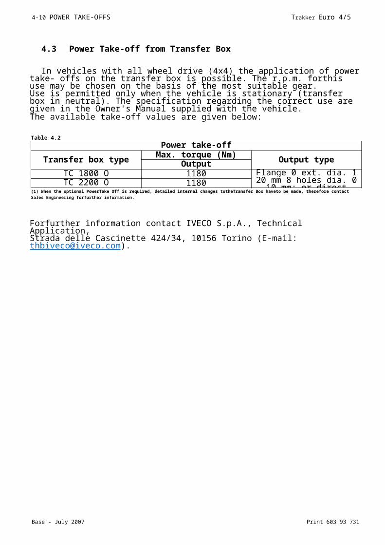
4.3 Power Take-off from Transfer Box
In vehicles with all wheel drive (4x4) the application of power take- offs on the transfer box is possible. The r.p.m. forthis use may be chosen on the basis of the most suitable gear.Use is permitted only when the vehicle is stationary (transfer box in neutral). The specification regarding the correct use are given in the Owner's Manual supplied with the vehicle.The available take-off values are given below:
Forfurther information contact IVECO S.p.A., Technical Application,Strada delle Cascinette 424/34, 10156 Torino (E-mail: [email protected]).
Table 4.2
Power take-off
Transfer box typeMax. torque (Nm)
Output typeOutputTC 1800 O 1180 Flange 0 ext. dia. 1 20
mm 8 holes dia. 0 10 mm; or direct pumps
TC 2200 O 1180(1) When the optional PowerTake Off is required, detailed internal changes totheTransfer Box haveto be made, therefore contact Sales Engineering forfurther information.
Base - July 2007 Print 603 93 731Power Take-off from Engine
4-10 POWER TAKE-OFFS Trakker Euro 4/5
Power Take-off from Transfer Box

Print 603 93 731 Base - July 2007
Trakker Euro 4/5 POWER TAKE-OFFS 4-11
4.4 Power Take-off from Drive line
The authorisation forthe application of a powertake-off on the drive line downstream ofthe gearbox is issued after examination
of the complete documentation presented to the Company.The various power and torque values will be evaluated as each occasion arises on the basis of the conditions of use.In general the following should be noted:- The drive take-off may be operated only when the vehicle is stationary.- The powertake-off r.p.m. is dependent on the gear selected.- The powertake-off must be located immediately downstream ofthe gearbox. For vehicles with the drive line in two or more
sections, the powertake-off may also be fitted at the flexible support included between the first and second sections (respectthe indications given in point 2.8.2).
- The angles of the drive line on the horizontal plane and vertical plane must be kept as close as possible to the original values.
- Masses and rigidity added to the drive line must not provoke a loss of balance or abnormal vibrations or damage the transmission
drive line (from engine to axle) either during vehicle movement or during operation with the motor running.
- The powertake-off must be fixed to the chassis with its own suspension.
As the transmission is an important part for the safety of the vehicle, modification to it must only be carried out by specialist companies approved by the supplier of the
transmission.Power Take-off from Drive line
NOTE
Base - July 2007 Print 603 93 731Power Take-off from Engine
4-12 POWER TAKE-OFFS Trakker Euro 4/5
4.5 Power Take-off from Engine
In general the use of these power take-offs is planned for apparatus requiring a continuous power supply.
4.5.1 Torque power take off from the front of the engine
The drive take-off from the front part of the crankshaft is obtained, for limited power values to be drawn off (e.g. air conditioning etc.) by drive belt transmission, the use of coupling shafts is normally reserved for take-offs of a greater magnitude (e.g. municipal use).These uses, when not specifically planned, require precise modifications to the front part of the vehicle, e.g. modifications to the radiator, cab, bumpers etc. Particular attention must therefore be paid:
- To the system comprising additional masses and relative rigidity which must be flexibly disengaged from the crankshaft with regard to the torsional and flexional effects.- To the additional mass values and relative moments of inertia and to the distance from the centre of gravity of the masses from the centreline of the first main bearing which must be kept to a minimum.
- To avoiding a reduction in the radiator cooling capacity and dead water areas.- To restoring the rigidity and resistance characteristics of the modified elements (cross member, bumper etc.).
- Toavoid exceeding, during extended use, temperatures of the engine cooling fluid of over I00°C andengine oil
temperature (measuredon the main duct of the pressure switch area) of 110 to I20°C. A margin of approx.10% shouldhowever
be left. In othercasesinclude supplementary heat exchangers.
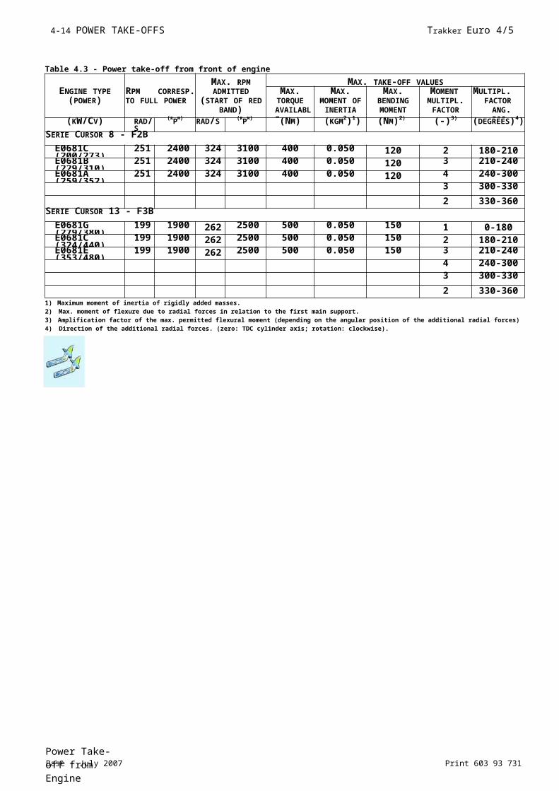
Table 4.3 shows the values to be referred to for the take-off.
Table 4.3 - Power take-off from front of engine
MAX. RPM MAX. TAKE-OFF VALUESENGINE TYPE
(POWER)RPM CORRESP. TO FULL POWER
ADMITTED (START OF RED
BAND)
MAX.TORQUEAVAILABLE
MAX.MOMENT
OF INERTIA
MAX.BENDINGMOMENT
MOMENTMULTIPL.FACTOR
MULTIPL. FACTOR ANG. (KW/CV) RAD
/S(RPM) RAD/S (RPM) (NM) (KGM2)1) (NM)2) (-)3) (DEGREES
)4)SERIE CURSOR 8 - F2B
E0681C (200/273)
251 2400 324 3100 400 0.050 120 2 180-210E0681B (229/310)
251 2400 324 3100 400 0.050 120 3 210-240E0681A (259/352)
251 2400 324 3100 400 0.050 120 4 240-3003 300-330
2 330-360SERIE CURSOR 13 - F3B
E0681G (279/380)
199 1900 262 2500 500 0.050 150 1 0-180E0681C (324/440)
199 1900 262 2500 500 0.050 150 2 180-210E0681E (353/480)
199 1900 262 2500 500 0.050 150 3 210-2404 240-3003 300-330
2 330-3601) Maximum moment of inertia of rigidly added masses.2) Max. moment of flexure due to radial forces in relation to the first main support.3) Amplification factor of the max. permitted flexural moment (depending on the angular position of the additional radial forces)4) Direction of the additional radial forces. (zero: TDC cylinder axis; rotation: clockwise).
Print 603 93 731 Base - July 2007
Trakker Euro 4/5 POWER TAKE-OFFS 4-13
Print 603 93 731 Base - July 2007Power Take-off from Engine
Trakker Euro 4/5 POWER TAKE-OFFS 4-1 1
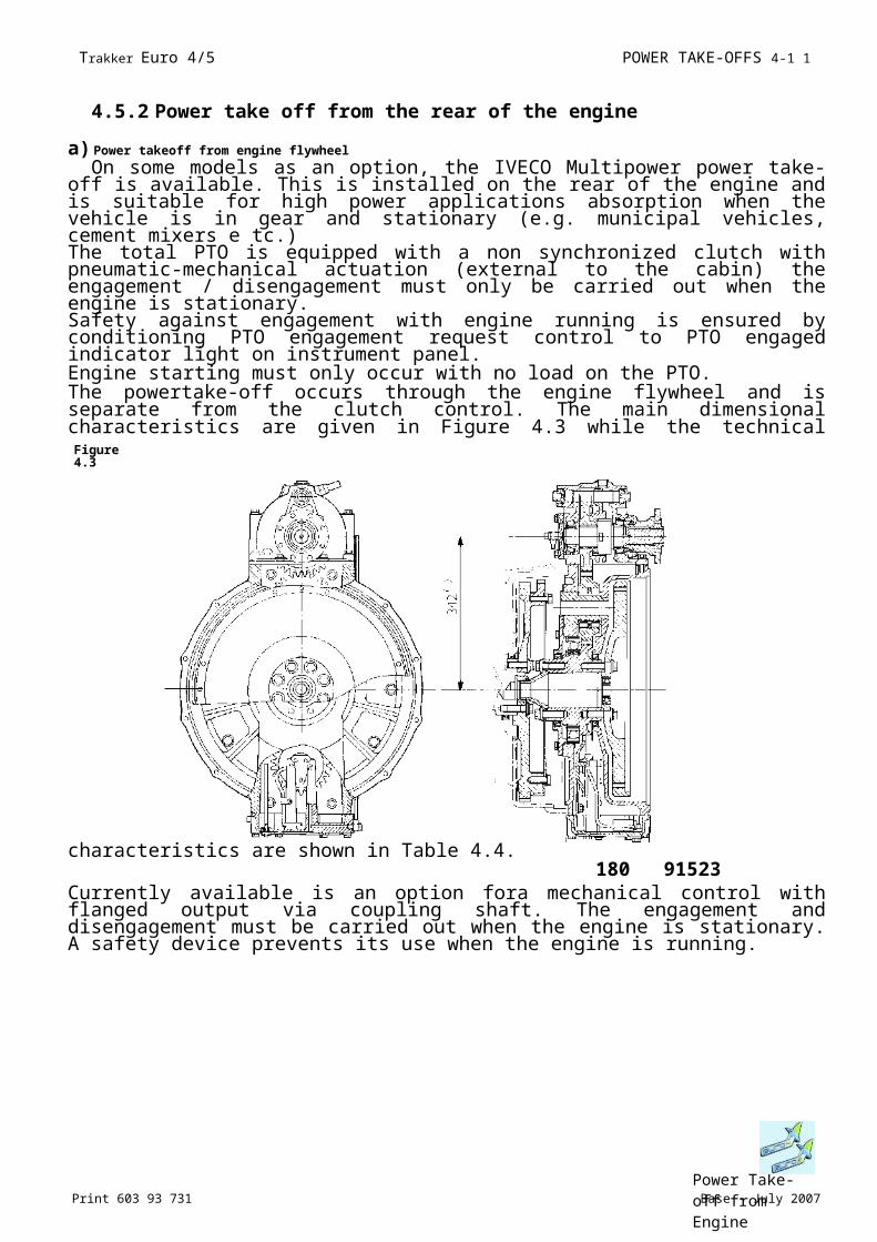
4.5.2 Power take off from the rear of the engine
a) Power takeoff from engine flywheel
On some models as an option, the IVECO Multipower power take-off is available. This is installed on the rear of the engine and is suitable for high power applications absorption when the vehicle is in gear and stationary (e.g. municipal vehicles, cement mixers e tc.)The total PTO is equipped with a non synchronized clutch with pneumatic-mechanical actuation (external to the cabin) the engagement / disengagement must only be carried out when the engine is stationary.Safety against engagement with engine running is ensured by conditioning PTO engagement request control to PTO engaged indicator light on instrument panel.Engine starting must only occur with no load on the PTO.The powertake-off occurs through the engine flywheel and is separate from the clutch control. The main dimensional characteristics are given in Figure 4.3 while the technical characteristics are shown in Table 4.4.
180 91523
Currently available is an option fora mechanical control with flanged output via coupling shaft. The engagement and disengagement must be carried out when the engine is stationary. A safety device prevents its use when the engine is running.
Figure 4.3
Power Take-off from EnginePrint 603 93 731 Base - July 2007
Trakker Euro 4/5 POWER TAKE-OFFS 4-15
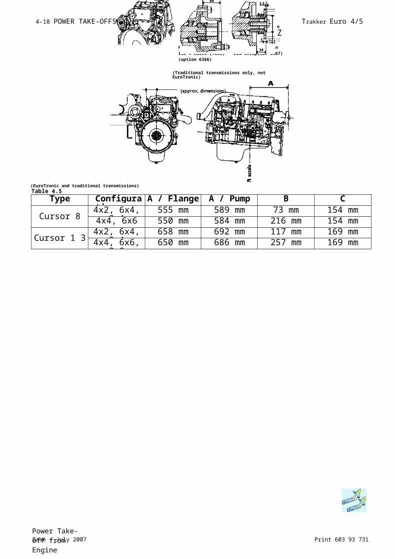
b) Power take-off from the timing gears at rear of engine
Models equipped with engines of the Cursor 8, Cursor 10 and Cursor 13 series are supplied with friction clutch power takeoff which picks motion from the distribution gears, independently from the vehicle's clutch.The power takeoff is available in the direct pump mount version, or with a flange for Cardan shaft.The installation of this power takeoff must be requested when ordering the vehicle; subsequent applications require the replacement of the whole engine.
Figure 4.4 shows diagrams with dimensions and position of the PTO in relation to the engine and vehicle.Table 4.5 gives the main data.To take off a max. torque of 600 Nm (CURSOR 8-10) and 800 Nm (CURSOR 13) the moment of inertia of the rotating masses, movement after the power take-off (including the coupling shaft), must be no greater than: 0.03 KGM2.In no case must the max. available torque of 600 Nm (CURSOR 8-10) and 800 Nm (CURSOR 13) be exceeded.
Direct pump application
The static moment due to the added masses must not exceed 90 Nm, measured on the pump mating surface.
Connection with coupling shaft
On exceeding the maximum admissible value of the inertia, given above, it is necessary to apply a flexible coupling, specifications of the coupling to be requested directly to IVECO.
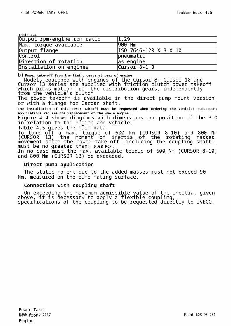
Table 4.4
Output rpm/engine rpm ratio 1.29Max. torque available 900 NmOutput flange ISO 7646-120 X 8 X 10Control pneumaticDirection of rotation as engineInstallation on engines Cursor 8-1 3
Base - July 2007 Print 603 93 731Power Take-off from Engine
4-16 POWER TAKE-OFFS Trakker Euro 4/5

Power Take-off from EnginePrint 603 93 731 Base - July 2007
Trakker Euro 4/5 POWER TAKE-OFFS 4-17
(EuroTronic and traditional transmissions)
o
Z□
Pump connection Flange connectionISO 4 holes (7653) DIN I0(option 5367)(option 6366)
(Traditional transmissions only, not EuroTronic)
position on the vehicle
Table 4.5
Type Configuration
A / Flange A / Pump B C
Cursor 84x2, 6x4,
8x4555 mm 589 mm 73 mm 154 mm
4x4, 6x6 550 mm 584 mm 216 mm 154 mm
Cursor 1 34x2, 6x4,
8x4658 mm 692 mm 117 mm 169 mm
4x4, 6x6, 8x8
650 mm 686 mm 257 mm 169 mm
Base - July 2007 Print 603 93 731Power Take-off from Engine
4-18 POWER TAKE-OFFS Trakker Euro 4/5
MultipowerThis specific powertake-off has the advantage that it is installed by Iveco and
allows coupling pumps required forsystem handling and remains engaged not only during equipment load/unload operations but also with the vehicle in motion (unless it is disengaged by the operator).While there are non problems with this particular powertakeoff during normal loading and unloading operations, and during vehicle movement, some problems may occur because of the Multipower rotating speed.As a matter of fact, the pumps connected to the Multipower, can reach a maximum rotation speed of 1800 r.p.m.; this value in fact according to the takeoff e multiplication function corresponds to a pump rotation speed of 2400 rpm.Therefore, in order to avoid problems with the pumps, after the PTO engagement and with the vehicle being driven the rotation speed of the engine must be limited to 1800 rpm.Consequently, in order to operate FMO equipment with this type of powertakeoff, the vehicle control unit must have the three following function modes enabled:1)Vehicle in motion
With Multipower engaged and the vehicle in motion, the vehicle control unit must receive the PTO engaged signal. Acceleration of the vehicle is permitted, but it is not allowed to exceed the 1800 rpm threshold, set in the program of the vehicle control unit.2)Pump engaged with accelerator de-activated
After engagement of the pump, if no part of the equipment is in operation (if no loading and unloading operations are being preformed and the compactor is not engaged), the vehicle control unit receives the pump engaged signal. The rotating speed, set by the vehicle control unit program, is kept to a minimum and accelerations from the operator are not permitted (if the accelerator pedal remains de-activated).
NOTE This condition can be found even when, the movement of the equipment is interrupted during operation because of an alarm.During emergency movements, for example for the return into the profile of the members, it isadvis- able to carry out the manoeuvres with a reduced motor rotation speed.
Rememberthat with these enabled pump without accelerator request conditions during normal operation may not be frequent: in fact the compactor is always on during normal equipment operation and this implies the accelerator enabling request.3)Pumps engaged with accelerator activated
After engauging the PTO pump and with the equipment in operation (loading, unloading and compacting operations), the vehicle control unit receives the accelerator request signal.The rotating speed set by means of the vehicle control unit, is carried to the optimal value required to obtain the oil flow capacity required for equipment operation.Even in this stage the operator cannot accelerate.Therefore, three different vehicle rotating speeds and thresholds are required and must be obtained by means of three different signals that are to be sent by the
FMO equipment without Multipower operate only on function 2 and 3.
I
I I
Power Take-off from EnginePrint 603 93 731 Base - July 2007
Trakker Euro 4/5 POWER TAKE-OFFS 4-19
equipment to the vehicle control unit.
Base - July 2007 Print 603 93 731Power Take-off from Engine
4-20 POWER TAKE-OFFS Trakker Euro 4/5
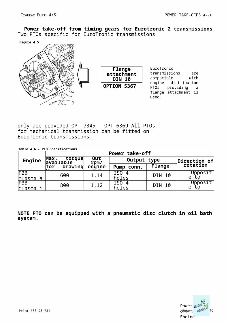
Power take-off from timing gears for Eurotronic 2 transmissionsTwo PTOs specific for EuroTronic transmissions only are
provided OPT 7345 - OPT 6369 All PTOs for mechanical transmission can be fitted on EuroTronic transmissions.
NOTE PTO can be equipped with a pneumatic disc clutch in oil bath system.
Figure 4.5
Flange attachment
DIN 10OPTION 5367
EuroTronic transmissions are compatible with engine distribution PTOs providing a flange attachment is used.
Table 4.6 - PTO Specifications
EnginePower take-off
Max. torque available for drawing Nm
Outrpm/
engine rpm
Output type Direction of rotationPump conn. Flange
conn.F2BCURSOR 8
600 1,14 ISO 4 holes (7653) DIN 10 Opposite
to engineF3BCURSOR 1
800 1,12 ISO 4 holes (7653) DIN 10 Opposite
to engine
Power Take-off from EnginePrint 603 93 731 Base - July 2007
Trakker Euro 4/5 POWER TAKE-OFFS 4-21

4-22 POWER TAKE-OFFS Trakker Euro 4/5
Base - July 2007 Print 603 93 731Power Take-off from Engine
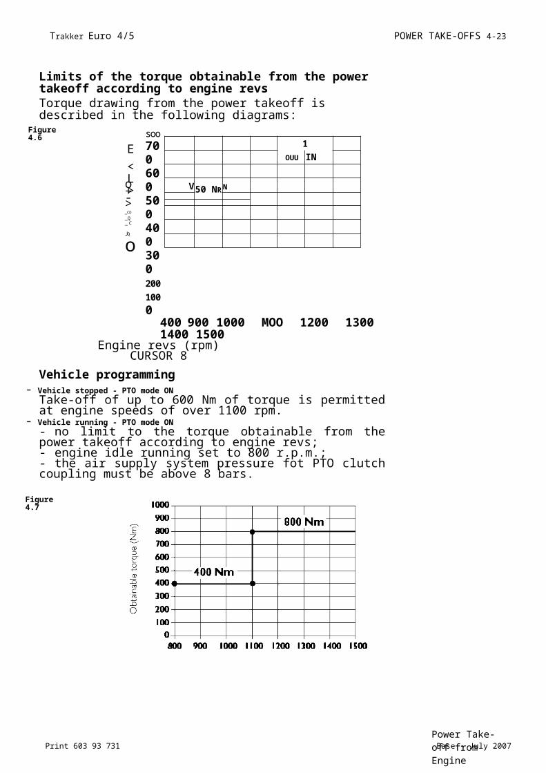
Limits of the torque obtainable from the power takeoff according to engine revsTorque drawing from the power takeoff is described in the following diagrams:
Engine revs (rpm)CURSOR 8
Vehicle programming- Vehicle stopped - PTO mode ON
Take-off of up to 600 Nm of torque is permitted at engine speeds of over 1100 rpm.
- Vehicle running - PTO mode ON- no limit to the torque obtainable from the power takeoff according to engine revs;- engine idle running set to 800 r.p.m.;- the air supply system pressure fot PTO clutch coupling must be above 8 bars.
Figure 4.7
Figure 4.6
E
<L>o+->
_CD
_Q_ C
JQ
o
soo700 600 500 400 300 20
0
10
0
0400 900 1000 MOO 1200 1300 1400 1500
1OUU IN III
V 50 NR
N
Trakker Euro 4/5 POWER TAKE-OFFS 4-23
Power Take-off from EnginePrint 603 93 731 Base - July 2007
Engine revs (rpm)CURSOR 1 3
Vehicle programming- Vehicle stopped - PTO mode ON
Torque drawing of 800 Nm is permitted over 1100 r.p.m.- Vehicle running - PTO mode ON
- no limit to the torque obtainable from the power takeoff according to engine revs;- engine idle running set to 700 r.p.m.;- the air supply system pressure for PTO clutch coupling must be above 8 bars.
4-24 POWER TAKE-OFFS Trakker Euro 4/5
Base - July 2007 Print 603 93 731
4.6 PTO management
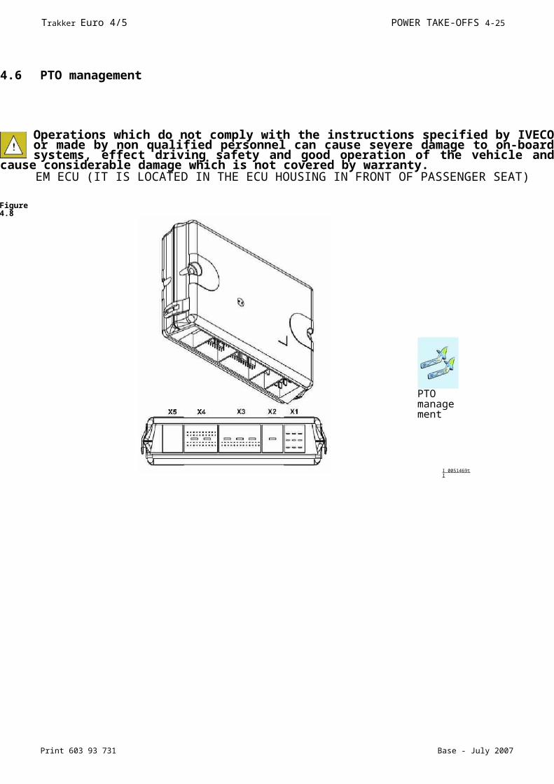
Operations which do not comply with the instructions specified by IVECO or made by non qualified personnel can cause severe damage to on-board systems, effect driving safety and good operation of the vehicle and cause
considerable damage which is not covered by warranty.EM ECU (IT IS LOCATED IN THE ECU HOUSING IN FRONT OF PASSENGER SEAT)
Figure 4.8
I 0051469t I
PTO management
Trakker Euro 4/5 POWER TAKE-OFFS 4-25
Print 603 93 731 Base - July 2007
4.6.1 General Specifications
Two operations are required to operate a PTO:1)mechanical PTO engagement;2) PTO mode to be associated to the PTO. See below for PTO mode definitions.The expression ”PTO active” indicates that the PTO is engaged and that one of the PTO modes is active; otherwise, it is said that the PTO is engaged only.Actions 1) and 2) can be carried out with two separate commands, in l)-2) sequence.3) A control carrying out actions 1 and 2 simultaneouslyIn general, PTO can be engaged by an electric command (triggered by a s olenoid valve) or by a pneumatic command.4) PTO cutout conditions
It is important to use the signals available on the bodybuilders connectors (e.g. parking brake applied, stationary vehicle signal, reverse gear not engaged) to ensure correct PTO management and avoid possible
damage to the vehicle’s mechanisms.These signals must exclusively be taken from the bodybuilders connections, STI4.
Based on required use, the body maker must address to IVECO service for ECU programming (Body Computer, ECU on gearbox if EuroTronic) that, together with EDC, manage PTO operation.With the assistance of tables contained in para below, the body maker can identify the configuration of the PTO control electronic system, herein conventionally called PTOI, 2 and 3. The body maker can choose, at the IVECO assistance network, one of the available configurations preset on EASY.
4.6.2 PTO 0 mode (run mode)
In normal operation, an intermediate rpm ratio can be activated to a speed of 30 km/h (important note: the speed regulator will trip at speeds exceeding 30 km/h). Press Resume on the steering wheel stalk unit to activate. A new intermediate r.p.m. can be memorised by the driver by pressing the Resume pushbutton for 3 to 10 seconds, in this case no IVECO Service reprogramming is required.The maximum rpm achievable with SET+ is identical for all modes.The minimum rpm achievable with SET- is identical for all modes. The idle speed adjustment range is exactly the same for all modes. Settings shown in the following table cannot be changed for PTO 0 mode (drive mode).
PTO management
- PTO 0 disabling speed(i)NLL N° revs when idling.
4-26 POWER TAKE-OFFS Trakker Euro 4/5
Base - July 2007 Print 603 93 731
4.6.3 Configurable PTO 1,2, 3 modes
IVECO Service can program three different, independent PTO mappings (engine operation settings) in the engine ECU (PTO). Obviously, the engine can only run according to one PTO mode at a time. The following priority order is used to solve this problem:- PTO mode 3: high priority- PTO mode 2: medium priority- PTO mode 1: low priority- PTO mode 0: driving mode
These priorities must be taken into account during reprogramming. Problems may arise if the sequence is not respected and the PTO wiring
may need to be modified. Alternatively, the VCM ECU may need to be reconfigured, etc.
The table below shows the parameters that, as a whole, constitute PTO mode. The parameters can only be programmed using the EASY test tool available a IVECO Service.
NOTE Updating with E.A.SY. software must be performed before using the MODUS station.
- PTO 0 disabling speed(i)NLL N° revs when idling.
i
PTO management
Possible power take-off rate range (1) NLL ^ 2700 rpm (2) per Cursor 8 NLL ^ 2340 rpm (2) per Cursor 1 3
Trakker Euro 4/5 POWER TAKE-OFFS 4-27
Print 603 93 731 Base - July 2007
Idling rpm Maximum rpmStored rpm press Resume or activate PTO mode to recall Maximum rpm achievable with SET+ button identical for all PTO modes Minimum rpm achievable with SET
(1) The reference speed is that of the crankshaft, not the PTO. The corresponding PTO rpm must be calculated by means of the PTO reduction ratio.
(2) The following rules refer to intermediate rpm ratio adjustment:- Never drop under the N|_i_ value.- Never exceed the Nmax value.- In general N|_i_ = NsET_min = Nres and Nres = NsET_max = Nmax. If the latter is not true, the engine rpm is limited to Nmax.
(3) See para. 4.6.3.I.(4) The TIP function (i.e. brief pressure on SET+/SET-toggle button for <1 s) is used to gradually vary the intermediate rpm regulator and the speed regulator.
The intermediate rpm regulator will be activated at speed <30 km/h; the speed regulator will be activated at speed > 30 km/h. The speed variation of the intermediate rpm regulator steps are equal to 20 rpm for tip, which corresponds to I km/h for the speed regulator.
(5) Active the power take off mode is disengaged when the service brake or the clutch pedals are pressed.Disabled the power take off mode is not disengaged when the service brake or the clutch pedals are pressed.In PTO mode 0, the power take off mode is disengaged when the service brake or the clutch pedals are pressed.
(6) Active the power take off mode is disengaged when the parking brake or the clutch pedals are pressed.Disabled the power take off mode is not disengaged when the parking brake or the clutch pedals are pressed.In PTO mode 0, the power take off mode is not disengaged when the parking brake is engaged.
the engine goes automatically to the chosen Nres value for that power take off mode.the engine remains at the previous rate, to reach the value Nres it is necessary to press the Resume button(pin 9 and 12 on the 21 pin connector).
PTO management
Possible power take-off rate range (1) NLL ^ 2700 rpm (2) per Cursor 8 NLL ^ 2340 rpm (2) per Cursor 1 3
Abbreviations:
NLLNmaxNresNSET_ max NSET_min
(7) Active Disabled
4-28 POWER TAKE-OFFS Trakker Euro 4/5
Base - July 2007 Print 603 93 731
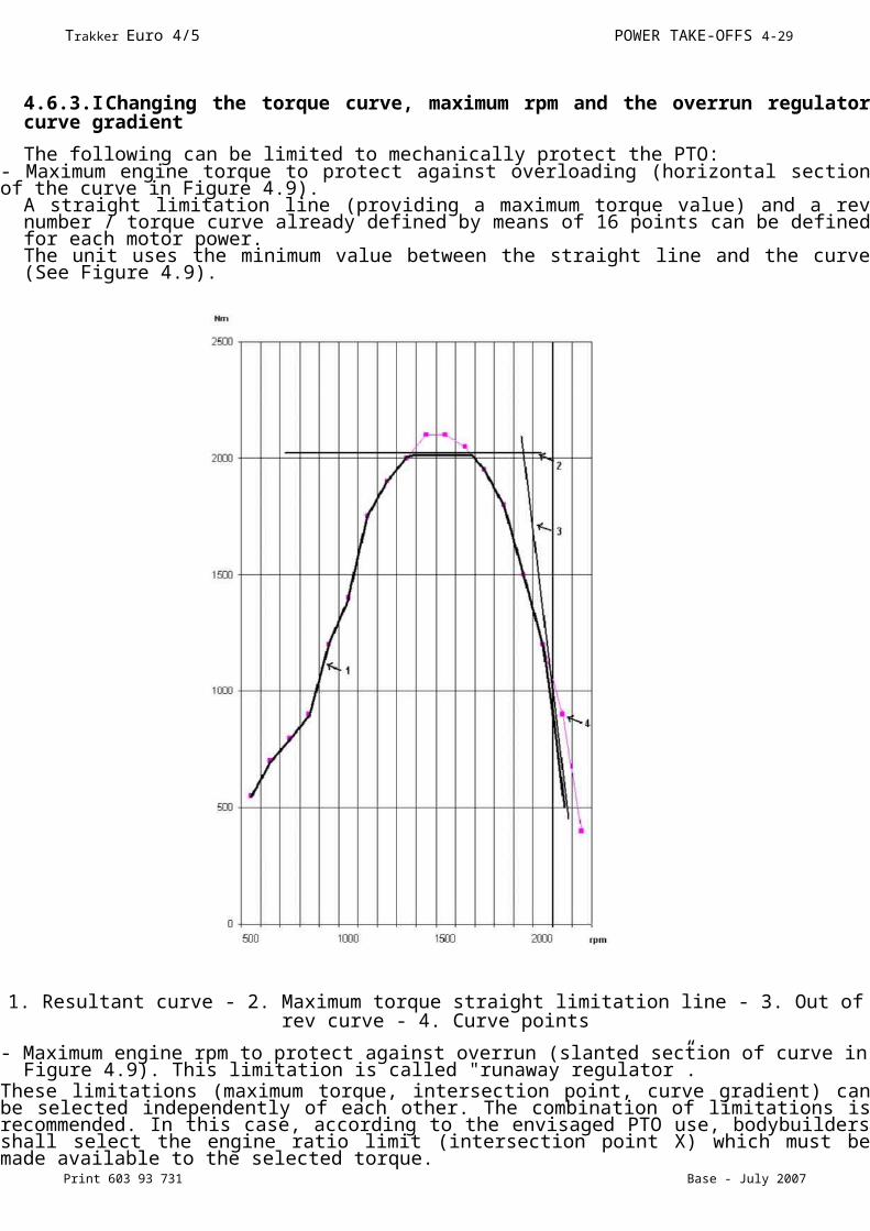
4.6.3.I Changing the torque curve, maximum rpm and the overrun regulator curve gradient
The following can be limited to mechanically protect the PTO:- Maximum engine torque to protect against overloading (horizontal section of the curve in Figure 4.9).
A straight limitation line (providing a maximum torque value) and a rev number / torque curve already defined by means of 16 points can be defined for each motor power.The unit uses the minimum value between the straight line and the curve (See Figure 4.9).
1. Resultant curve - 2. Maximum torque straight limitation line - 3. Out of rev curve - 4. Curve points
- Maximum engine rpm to protect against overrun (slanted section of curve in Figure 4.9). This limitation is called "runaway regulator”.
These limitations (maximum torque, intersection point, curve gradient) can be selected independently of each other. The combination of limitations is recommended. In this case, according to the envisaged PTO use, bodybuilders shall select the engine ratio limit (intersection point X) which must be made available to the selected torque.
Trakker Euro 4/5 POWER TAKE-OFFS 4-29
Print 603 93 731 Base - July 2007
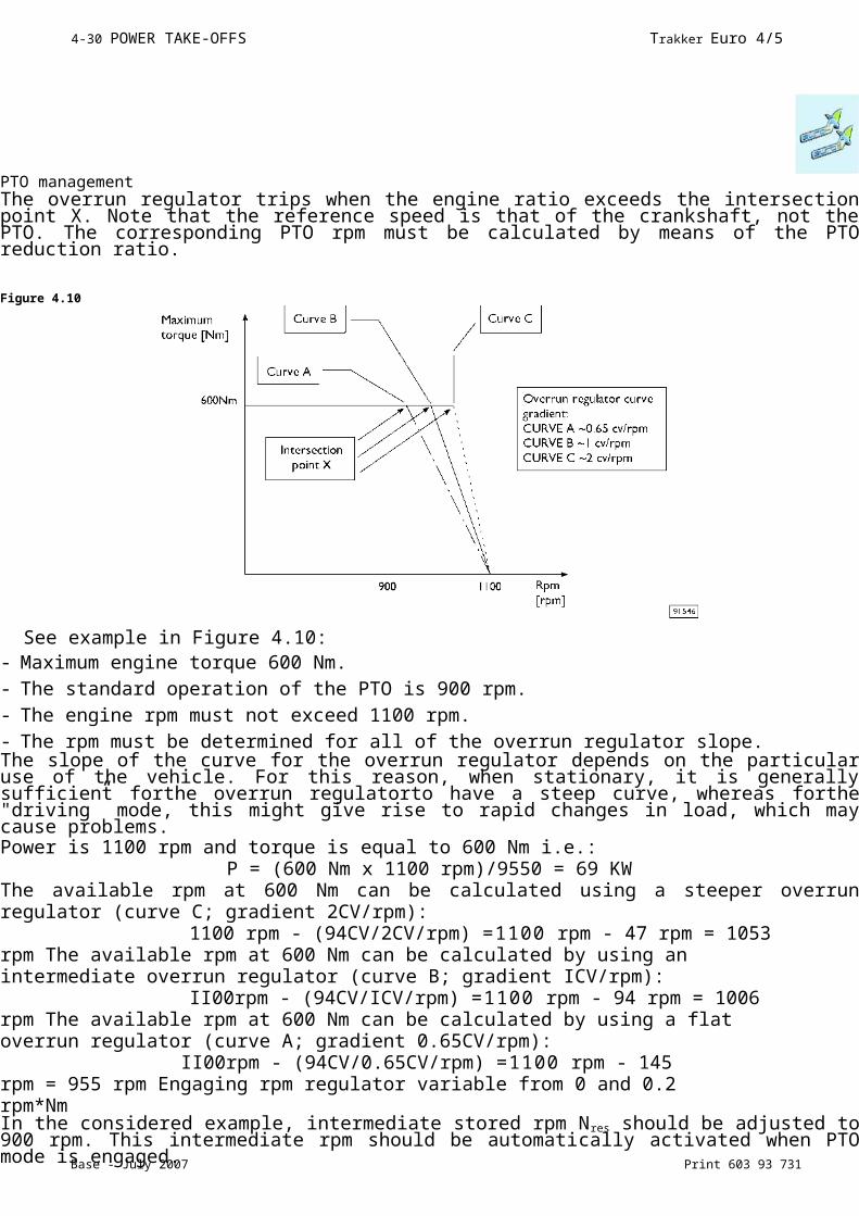
The overrun regulator trips when the engine ratio exceeds the intersection point X. Note that the reference speed is that of the crankshaft, not the PTO. The corresponding PTO rpm must be calculated by means of the PTO reduction ratio.
Figure 4.10
See example in Figure 4.10:- Maximum engine torque 600 Nm.
- The standard operation of the PTO is 900 rpm.
- The engine rpm must not exceed 1100 rpm.
- The rpm must be determined for all of the overrun regulator slope.The slope of the curve for the overrun regulator depends on the particular use of the vehicle. For this reason, when stationary, it is generally sufficient forthe overrun regulatorto have a steep curve, whereas forthe "driving” mode, this might give rise to rapid changes in load, which may cause problems.Power is 1100 rpm and torque is equal to 600 Nm i.e.:
P = (600 Nm x 1100 rpm)/9550 = 69 KWThe available rpm at 600 Nm can be calculated using a steeper overrun regulator (curve C; gradient 2CV/rpm):
1100 rpm - (94CV/2CV/rpm) =1100 rpm - 47 rpm = 1053 rpm The available rpm at 600 Nm can be calculated by using an intermediate overrun regulator (curve B; gradient ICV/rpm):
II00rpm - (94CV/ICV/rpm) =1100 rpm - 94 rpm = 1006 rpm The available rpm at 600 Nm can be calculated by using a flat overrun regulator (curve A; gradient 0.65CV/rpm):
II00rpm - (94CV/0.65CV/rpm) =1100 rpm - 145 rpm = 955 rpm Engaging rpm regulator variable from 0 and 0.2 rpm*NmIn the considered example, intermediate stored rpm Nres should be adjusted to 900 rpm. This intermediate rpm should be automatically activated when PTO mode is engaged.The example shows the impact of the overrun regulator. Depending on the usage the chosen torque of 600 Nm is available up to I055 rpm, I005 rpm or 955 rpm.The same is true in reverse, when engine torque, intersection point X and overrun regulator curve inclination are predefined, it is possible to calculate the final rpm speed.
PTO management
4-30 POWER TAKE-OFFS Trakker Euro 4/5
Base - July 2007 Print 603 93 731
PTO management
Trakker Euro 4/5 POWER TAKE-OFFS 4-31
Print 603 93 731 Base - July 2007
The maximum rpm Nmax is a theoretical value. This is the rpm at which the ECU reduces the injected amount of fuel at 0 mg/stroke. Considering that all engines, according to the rpm (engine hot and no load) need 20*30 mg/stroke of fuel to maintain the rpm, this theoretical value Nmax is never reached. According to the slope of the overrun regulator, the rpm actually reached is 10*40 rpm lower. You are advised to define overrun ratio by means of practical tests if this is likely to effect the application.
4.6.4 Intermediate rpm regulator
Maximum intermediate rpm regulator setting that can be achieved with SET+, NsET_max
TThe TIP function, i.e. a very short press (< 1s) on the SET+/SET- keys, allows a gradual change in the intermediate speed regulator or speed regulator. With speed <V0 (max speed of PTO mode) km/h, the intermediate rpm governor can be activated.With speed >V0 km/h, the speed governor is activated. The change for the intermediate speed regulator is equal to 20 rpm rpm for each TIP i.e. 1 km/h for each TIP with the speed regulator.The intermediate rpm or speed value is modified continuously by pressing the SET+ and SET- buttons for more than (>1 s). The effective rpm and effective speed when the SET+ and SET- buttons are released and stored as the new value.Function TIP with SET + and SET - can be disengaged. This configuration is applicableto all PTO modes simultaneously (drive mode 0, PTO mode 1,2 and 3). Function TIP disengagement activates the speed limiter operation limitation. Therefore, this change should only be operated after an in-depth analysis.
NOTE This function is provided for the regulation of hydraulic units.
Increasing/decreasing rpm with SET+/SET-
The intermediate rpm regulator value can be changed by pressing the SET+/SET- buttons for more than (>1 s) or when the TIP function is deactivated by a certain speed (engine rpm increase/decrease per second). The time interval for this change can be calculated using the following formula:
Time required [s] = Rpm difference [rpm/s] / rpm increase per second [rpm/s /s]
Example: take the intermediate rpm from 800 rpm to 1800 rpm using the SET + button. The difference in rpm is equal to 1000 rpm, consequently:- At a speed of 250 rpm/s, the time interval is 1000/250 = 4s
Activating/deactivating the accelerator pedal
The accelerator pedal is always active in normal driving mode (PTO mode 0). The accelerator pedal can be deactivated in PTO modes 1,2 or 3. In this case, PTO engine regulation will ignore the accelerator pedal. If the accelerator pedal is active, the engine rpm can be increased by means of the pedal to the maximum
PTO management
4-32 POWER TAKE-OFFS Trakker Euro 4/5
Base - July 2007 Print 603 93 731
rpm Nmax valid at the time.

Trakker Euro 4/5 POWER TAKE-OFFS 4-33
Print 603 93 731 Base - July 2007
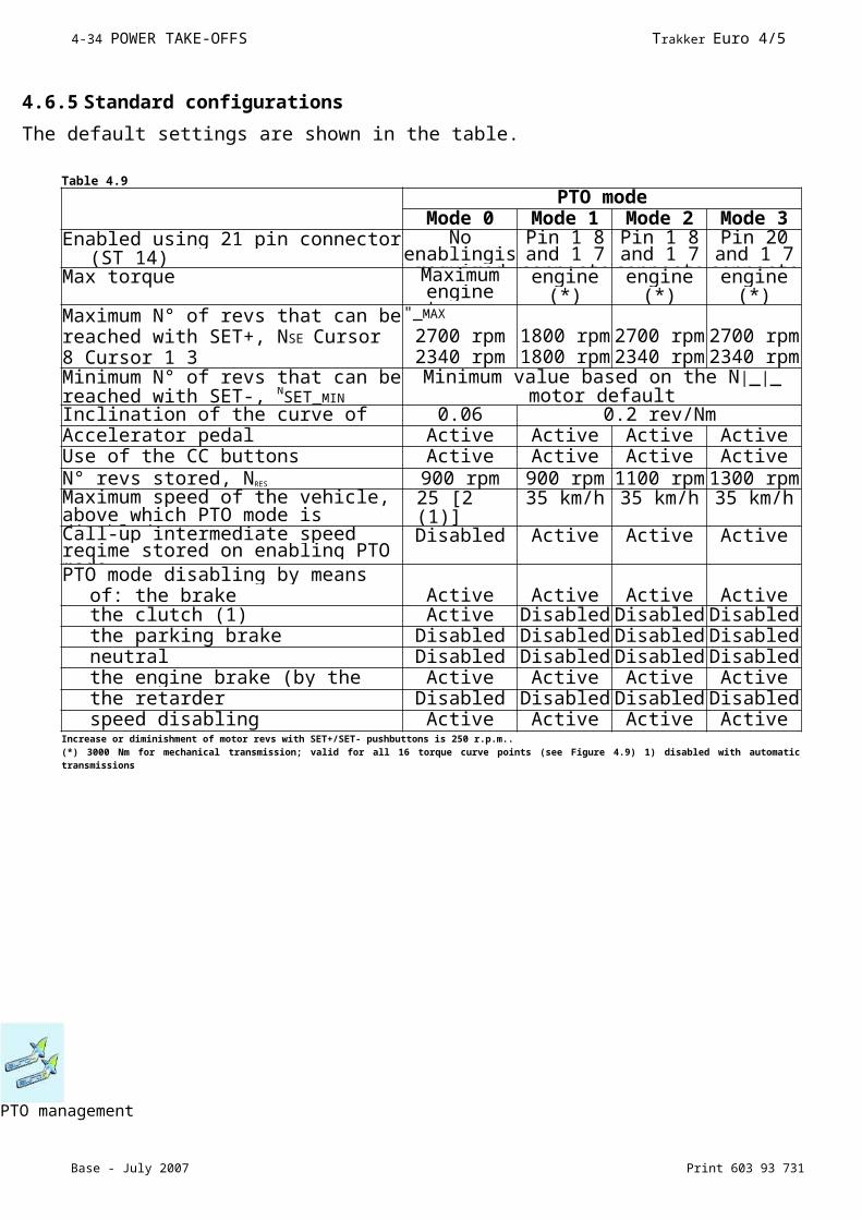
4.6.5 Standard configurations
The default settings are shown in the table.
4.6.6 Specific indications: correlation between the VCM configuration and the installed power take offs
There is no direct connection between the PTO powertake off mode (which can be activated
PTO management
Table 4.9
PTO modeMode 0 Mode 1 Mode 2 Mode 3
Enabled using 21 pin connector (ST 14)
No enablingis required
Pin 1 8 and 1 7
connecte
Pin 1 8 and 1 7
connecte
Pin 20 and 1 7
connecteMax torque Maximum engine torque
engine (*)
engine (*)
engine (*)
Maximum N° of revs that can be reached with SET+, NSE Cursor 8 Cursor 1 3
"_MAX
2700 rpm 2340 rpm
1800 rpm 1800 rpm
2700 rpm 2340 rpm
2700 rpm 2340 rpm
Minimum N° of revs that can be reached with SET-, NSET_MIN
Minimum value based on the N|_|_ motor default
Inclination of the curve of the out of rev regualtor ranging
0.06 rev/Nm
0.2 rev/NmAccelerator pedal Active Active Active ActiveUse of the CC buttons
(Resume/SET+/SET-)Active Active Active Active
N° revs stored, NRES 900 rpm 900 rpm 1100 rpm1300 rpmMaximum speed of the vehicle, above which PTO mode is disabled, VZDR_MAX
25 [2 (1)] km/h
35 km/h 35 km/h 35 km/h
Call-up intermediate speed regime stored on enabling PTO mode
Disabled Active Active Active
PTO mode disabling by means of: the brake Active Active Active Activethe clutch (1) Active Disabled Disabled Disabledthe parking brake Disabled Disabled Disabled Disabledneutral Disabled Disabled Disabled Disabledthe engine brake (by the driver) Active Active Active Activethe retarder Disabled Disabled Disabled Disabledspeed disabling Active Active Active Active
Increase or diminishment of motor revs with SET+/SET- pushbuttons is 250 r.p.m..(*) 3000 Nm for mechanical transmission; valid for all 16 torque curve points (see Figure 4.9) 1) disabled with automatic transmissions
4-34 POWER TAKE-OFFS Trakker Euro 4/5
Base - July 2007 Print 603 93 731
using the 21 -pin connector) and the powertake offs physically fitted to the vehicle. Therefore, the bodybuilder can define the necessary connections as suits him. This set up therefore makes it possible to use the powertake off(s) with the various PTO configurations (for example, for particular work cycles). Should a work cycle be established, for example, in which the fitted powertake off is made to operate in different conditions, then up to a maximum of 3 modes for the PTO powertake off can be used. The corresponding PTO powertake off modes must be activated from the body/ancillary at the relevant times.In a similar way, it is possible to correlate an PTO powertake off mode even without there being a powertake off physically fitted to the vehicle, or conversely when there is more than one fitted.
4.6.7 Engaging the power take off
The power take-offs fitted on the gearbox can only be engaged with the clutch fully pressed. The PTO mode power take-offs, on the other hand, can be enabled independent of the above.
4.6.8 With Allison Gearbox
When the vehicle has an Allison gearbox, the selection of the powertake off is co-ordinated by the gearbox central control unit. The operation uses the following procedure:
- request to engage the powertake off (the gearbox central control unit checks the internal conditions so that the operation can be effected safely: engine speed less than 900 rpm and output speed from the gearbox less than 250 rpm);
- the solenoid valve used to engage the powertake off is activated by the central control unit;- a check is made that the powertake off is functioning safely (output speed from the gearbox less than 300 rpm).
The button for engaging the powertake off is located in the central section of the dashboard.
““ Before engaging the power take off, the gearbox central control unit checks a number of parameters (engine speed is less than 900 rpm and
output speed from the gearbox is less than 250 rpm).A
If all the necessary conditions inside the gearbox are satisfied, the Allison gearbox central control unit automatically engages the power take off. The restrictions (end speed, maximum torque etc) for the PTO power take off mode selected therefore remain valid even while the engagement takes place.Certain values may be modified by Allison Customer Assistance, as required by the bodybuilder.
4.6.9 Use of the power take-off with vehicle in motion
If restrictions are not required (e.g. restrictions on torque, reduced maximum number of engine revs, etc) when the powertake off is engaged, it is not necessary to use any PTO powertake off mode.In this case, however, the engine power available for running the vehicle is reduced (given that power is being taken simultaneously by the ancillary). This could lead to acceleration problems. In typical usages (e.g. cement mixers, refuse collection vehicles etc) this problem can be minimised by increasing the idling speed. This increased number of revs would, however, also then be present even when the powertake off was disengaged. In general, a reduction in the maximum torque in this field of operation would not be considered sensible.If, however, restrictions are required (e.g. restrictions on torque, reduced maximum number of engine revs, etc) then an PTO power take off mode should be used.
Trakker Euro 4/5 POWER TAKE-OFFS 4-35
Print 603 93 731 Base - July 2007
PTO management

4-36 POWER TAKE-OFFS Trakker Euro 4/5
Base - July 2007 Print 603 93 731
Particularly when the vehicle is operational, care must be taken to ensure that if an PTO power take off mode is activated, then the stored intermediate number of revs must also be activated at the same time. This could, however, result in an unexpected increase in vehicle speed. It
is the bodybuilder’s responsibility to ensure that the chosen solution is safe.
The engagement or disengagement of the power take off depends both on the power take off chosen and the requirements of the bodybuilder.Regarding vehicle operation (up to a maximum speed of 30 km/h) with an increased number of revs when the power take off is engaged. Fora range of applications, (e.g. use of a tipping body, cement mixer, refuse collection etc) higher revs are also required during operation. This can be achieved using the following set up:- Stored intermediate number of revs Nres: fixed programming- Intermediate number of revs (Nres): as defined by the bodybuilder- Disengagement of the intermediate number of revs: deactivated via the clutch or brake pedals
- Accelerator pedal: activated- CC Buttons: deactivatedIn this way, the engine can only operate again when the accelerator pedal is regulated between the stored intermediate number of revs, Nres, and the maximum number of revs, Nmax. IfVZDR-aus is ever reached, the intermediate number of revs and therefore also the increase in revs is deactivated.
Changing the stored intermediate number of revs Nres
The intermediate number of revs can be modified separately for each PTO power take off mode.
It is necessary to distinguish between two possibilities:1)Fixed programming (E.A.SY.)
For mode 0 power takeoff (driving mode), this mode is not available. A modification is only possible by reprogramming the E.A.SY. test tool at IVECO Service
2) Free programming (by the driver)To modify the intermediate number of revs, the following procedure is used:
a) select the particular PTO power take off mode whose intermediate number of revs are to beb) set the desired intermediate number of revs using the SET+/SET- button;c) press and hold CC Resume for 3 to 10 seconds.
NOTE Updating with E.A.SY. software must be performed before using the MODUS station.
The minimum number of revs reachable can be regulated by means of the SET-, NSET_min pushbutton for PTO 0
The idling speed must only be set when the engine is warm. There are three stages in the process:
1) Idle running actuationThe engine must operate at idling speed.
- Actuate the service brake (until the end of adjustment)- Press and hold the Resume pushbutton for 3 to 7 seconds.
Immediately afterwards, the idling speed reduces automatically to the minimum value. Actuate the service brake (until the end of adjustment).
I
PTO manag
Trakker Euro 4/5 POWER TAKE-OFFS 4-37
Print 603 93 731 Base - July 2007
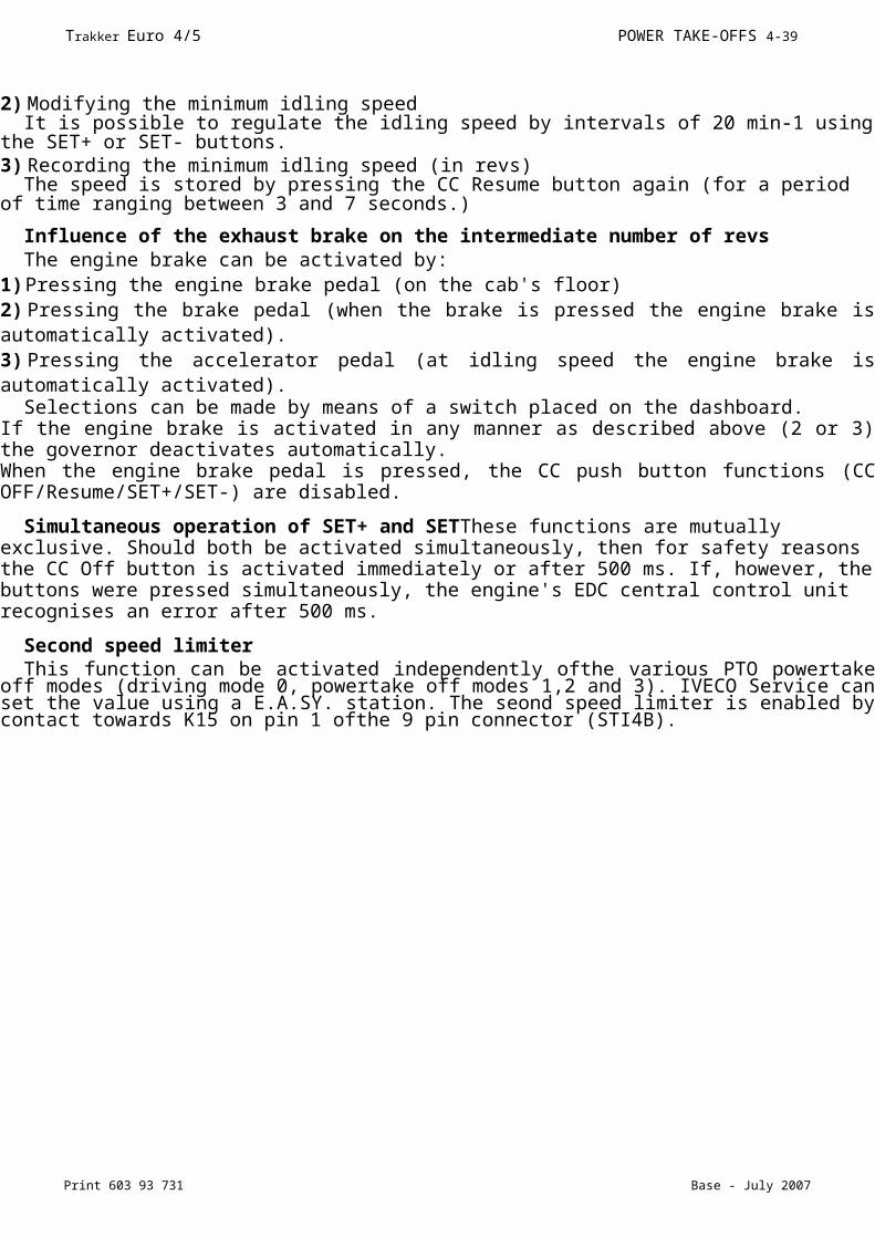
2) Modifying the minimum idling speedIt is possible to regulate the idling speed by intervals of 20 min-1 using the SET+ or SET-
buttons.3) Recording the minimum idling speed (in revs)
The speed is stored by pressing the CC Resume button again (for a period of time ranging between 3 and 7 seconds.)
Influence of the exhaust brake on the intermediate number of revsThe engine brake can be activated by:
1)Pressing the engine brake pedal (on the cab's floor)2) Pressing the brake pedal (when the brake is pressed the engine brake is automatically activated).3) Pressing the accelerator pedal (at idling speed the engine brake is automatically activated).
Selections can be made by means of a switch placed on the dashboard.If the engine brake is activated in any manner as described above (2 or 3) the governor deactivates automatically.When the engine brake pedal is pressed, the CC push button functions (CC OFF/Resume/SET+/SET-) are disabled.
Simultaneous operation of SET+ and SETThese functions are mutually exclusive. Should both be activated simultaneously, then for safety reasons the CC Off button is activated immediately or after 500 ms. If, however, the buttons were pressed simultaneously, the engine's EDC central control unit recognises an error after 500 ms.
Second speed limiterThis function can be activated independently ofthe various PTO powertake off modes (driving
mode 0, powertake off modes 1,2 and 3). IVECO Service can set the value using a E.A.SY. station. The seond speed limiter is enabled by contact towards K15 on pin 1 ofthe 9 pin connector (STI4B).
NOTE The use of the MODUS station must take place after an upgrade is run using E.A.SY. software

4-38 POWER TAKE-OFFS Trakker Euro 4/5
Base - July 2007 Print 603 93 731
4.7 EM (Expansion Module)
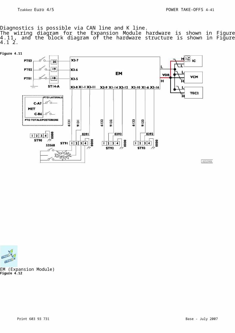
The optional 4572, EM (Expansion Module), is available on all the new Trakker.The EM control unit can be used for electrical management of the PTO and for special applications. Also provides special gateways such as: trailer interface ISO 11992-3 (TT) and CAN OPEN interface (BB in development phase).Diagnostics is possible via CAN line and K line.The wiring diagram for the Expansion Module hardware is shown in Figure 4.11, and the block diagram of the hardware structure is shown in Figure 4.1 2.
Figure 4.11
PTO management
Trakker Euro 4/5 POWER TAKE-OFFS 4-39
Print 603 93 731 Base - July 2007
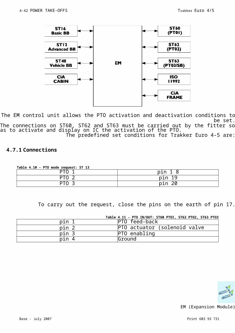
Figure 4.12
The EM control unit allows the PTO activation and deactivation conditions to be set.The connections on ST60, ST62 and ST63 must be carried out by the fitter so as to activate and display on IC the activation of the PTO.The predefined set conditions for Trakker Euro 4-5 are:
4.7.1 Connections
To carry out the request, close the pins on the earth of pin 17.
EM (Expansion Module)
Table 4.10 - PTO mode request: ST 13
PTO 1 pin 1 8PTO 2 pin 19PTO 3 pin 20
Table 4.11 - PTO IN/OUT: ST60 PTOI, ST62 PTO2, ST63 PTO3
pin 1 PTO feed-backpin 2 PTO actuator (solenoid valve control)pin 3 PTO enablingpin 4 Ground
4-40 POWER TAKE-OFFS Trakker Euro 4/5
Base - July 2007 Print 603 93 731
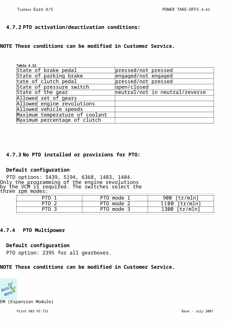
EM (Expansion Module)4.7.2 PTO activation/deactivation conditions:
NOTE These conditions can be modified in Customer Service.
4.7.3 No PTO installed or provisions for PTO:
Default configuration
PTO options: 5439, 5194, 6368, 1483, 1484.Only the programming of the engine revolutions by the VCM is required. The switches select the three rpm modes:
4.7.4 PTO Multipower
Default configuration
PTO option: 2395 for all gearboxes.
NOTE These conditions can be modified in Customer Service.
Table 4.12
State of brake pedal pressed/not pressedState of parking brake engaged/not engagedtate of clutch pedal pressed/not pressedState of pressure switch open/closedState of the gear neutral/not in neutral/reverseAllowed set of gearsAllowed engine revolutionsAllowed vehicle speedsMaximum temperature of coolantMaximum percentage of clutch slipping
PTO 1 PTO mode 1 900 [tr/mln]PTO 2 PTO mode 2 1100 [tr/mln]PTO 3 PTO mode 3 1300 [tr/mln]
Trakker Euro 4/5 POWER TAKE-OFFS 4-41
Print 603 93 731 Base - July 2007
EM (Expansion Module)
4-42 POWER TAKE-OFFS Trakker Euro 4/5
Base - July 2007 Print 603 93 731
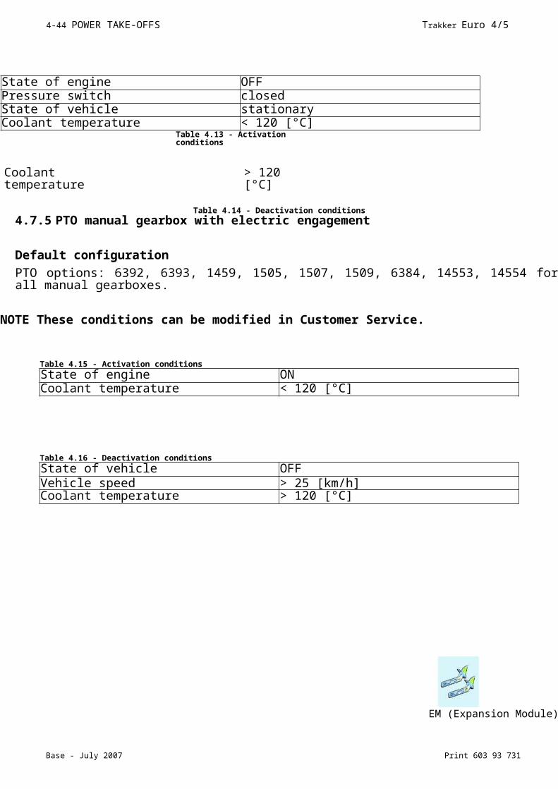
State of engine OFFPressure switch closedState of vehicle stationaryCoolant temperature < 120 [°C]
Table 4.14 - Deactivation conditions4.7.5 PTO manual gearbox with electric engagement
Default configuration
PTO options: 6392, 6393, 1459, 1505, 1507, 1509, 6384, 14553, 14554 for all manual gearboxes.
NOTE These conditions can be modified in Customer Service.
EM (Expansion Module)
Coolant temperature
> 120 [°C]
Table 4.13 - Activation conditions
Table 4.15 - Activation conditions
State of engine ONCoolant temperature < 120 [°C]
Table 4.16 - Deactivation conditions
State of vehicle OFFVehicle speed > 25 [km/h]Coolant temperature > 120 [°C]
Trakker Euro 4/5 POWER TAKE-OFFS 4-43
Print 603 93 731 Base - July 2007
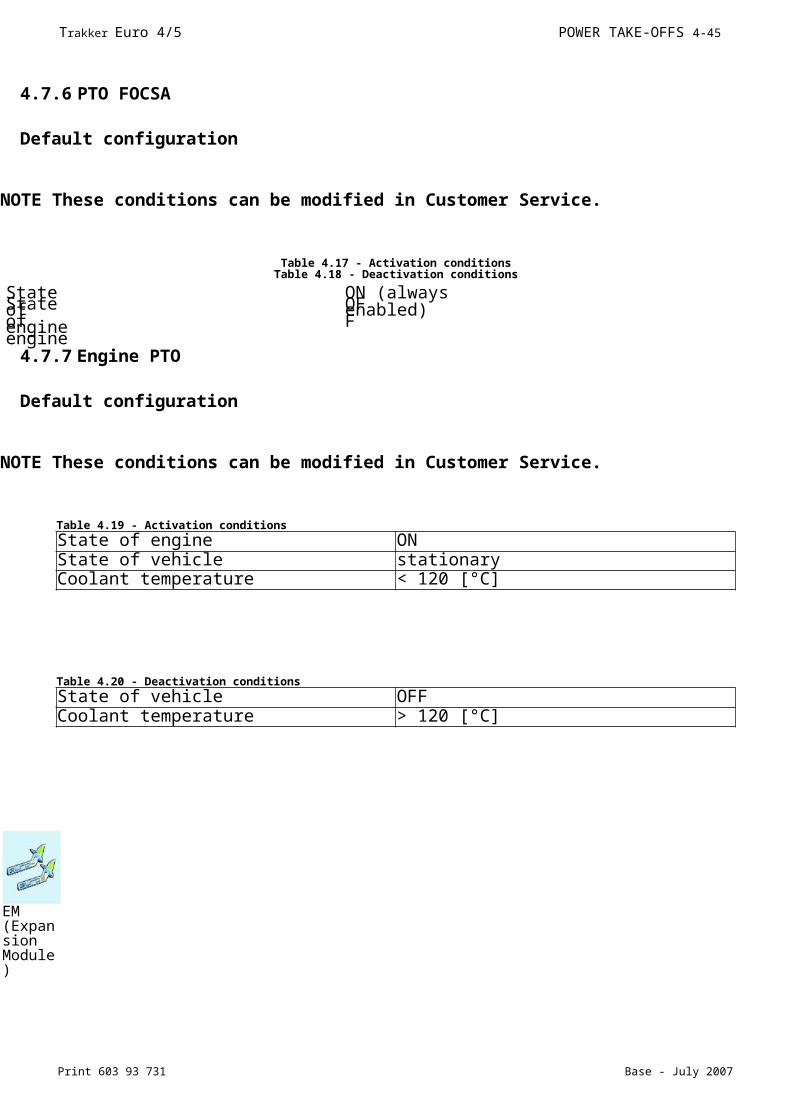
4.7.6 PTO FOCSA
Default configuration
NOTE These conditions can be modified in Customer Service.
Table 4.17 - Activation conditionsTable 4.18 - Deactivation conditions
4.7.7 Engine PTO
Default configuration
NOTE These conditions can be modified in Customer Service.
State of engine
ON (always enabled)State of
engineOFF
EM (Expansion Module)
Table 4.19 - Activation conditions
State of engine ONState of vehicle stationaryCoolant temperature < 120 [°C]
Table 4.20 - Deactivation conditions
State of vehicle OFFCoolant temperature > 120 [°C]
4-44 POWER TAKE-OFFS Trakker Euro 4/5
Base - July 2007 Print 603 93 731
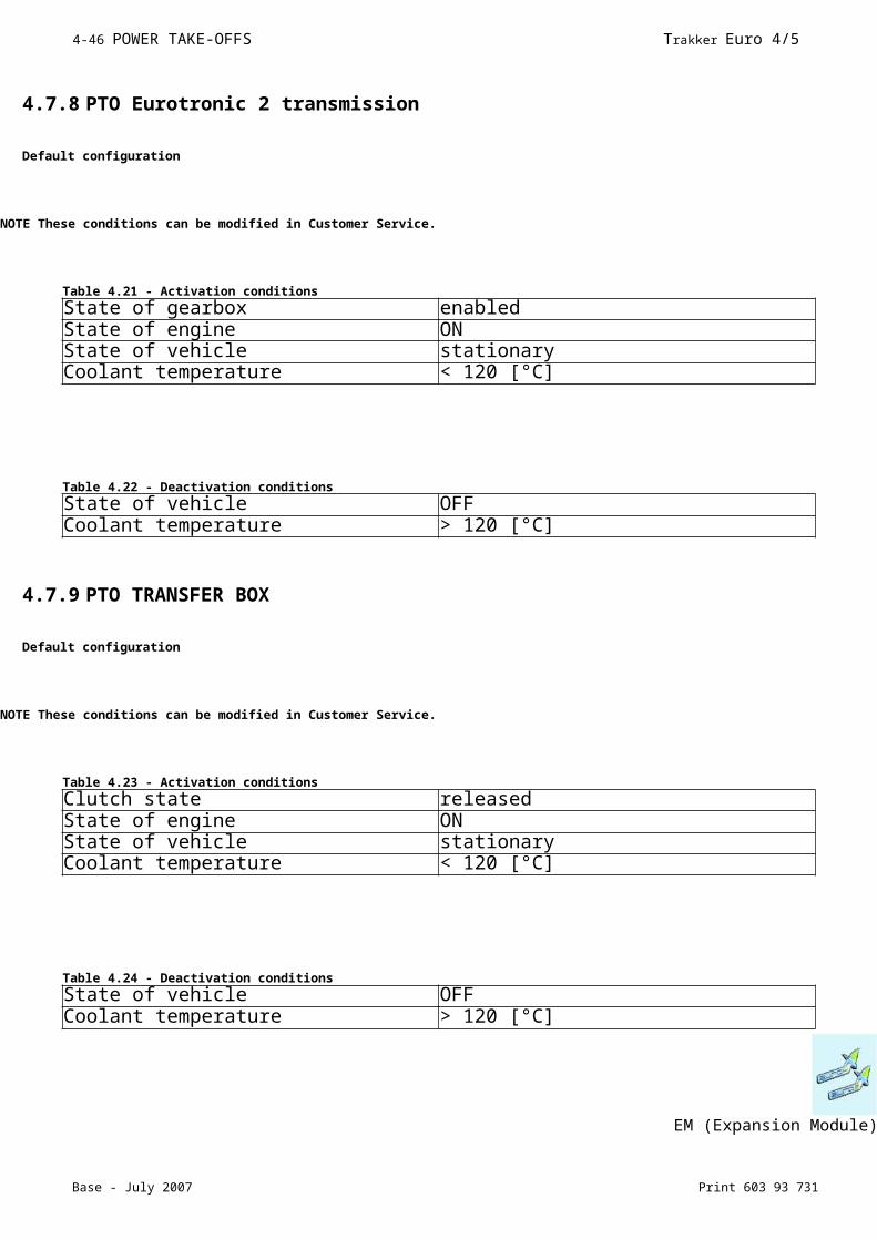
4.7.8 PTO Eurotronic 2 transmission
Default configuration
NOTE These conditions can be modified in Customer Service.
4.7.9 PTO TRANSFER BOX
Default configuration
NOTE These conditions can be modified in Customer Service.
EM (Expansion Module)
Table 4.21 - Activation conditions
State of gearbox enabledState of engine ONState of vehicle stationaryCoolant temperature < 120 [°C]
Table 4.22 - Deactivation conditions
State of vehicle OFFCoolant temperature > 120 [°C]
Table 4.23 - Activation conditions
Clutch state releasedState of engine ONState of vehicle stationaryCoolant temperature < 120 [°C]
Table 4.24 - Deactivation conditions
State of vehicle OFFCoolant temperature > 120 [°C]
Trakker Euro 4/5 POWER TAKE-OFFS 4-45
Print 603 93 731 Base - July 2007
EM (Expansion Module)
Print 603 93 731 Base - July 2007
Trakker Euro 4/5 SPECIAL INSTRUCTIONS FOR ELECTRONIC SUBSYSTEMS 5- 1
SECTION 5
Special instructions for electronic subsystems
Page
Index
Index
5.1 Multiplex system (MUX) 5-35.1.1 Description of MUX ECUs 5-3
5.I.I.I Instrument Cluster (IC) 5-45.I.I.2 Iveco Body Controller (IBC3) 5-45.I.I.3 Terminal board (electrical circuit passage) 5-55.I.I.4 MET frame module control unit 5-5
5.2 Bodybuilder connectors 5-65.2. I In the cab 5-65.2.2 On frame 5-1 I5.2.3 Truck/trailer connectors 5-14
5.3 Electrical circuit modifications 5-1 65.3. I Introduction 5-1 65.3.2 Wiring harness length 5-1 65.3.3 Repositioning ECUs 5-195.3.4 Disconnecting ECUs 5-20
5.4 FMS 5-2I

Base - July 2007 Print 603 93 731
5-2 SPECIAL INSTRUCTIONS FOR ELECTRONIC SUBSYSTEMS Trakker Euro 4/5
NOTE This chapter contains important information concerning the electronic network (MUX) installed on Trakker.
5.1 Multiplex system (MUX)
Trakker is equipped with an innovative electronic system, Multiplex (EASY MUX). The system electronically manages and controls the vehicle subsystems on CAN lines. The most important characteristics of MUX devices are shown in the paragraphs that follow.
5.1.1 Description of MUX ECUs
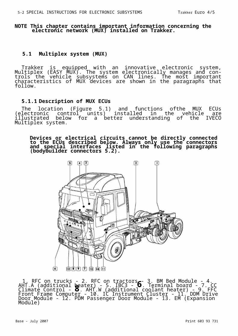
The location (Figure 5.1) and functions ofthe MUX ECUs (electronic control units) installed in the vehicle are illustrated below for a better understanding of the IVECO Multiplex system.
Devices or electrical circuits cannot be directly connected to the ECUs described below. Always only use the connectors and special interfaces listed in the following paragraphs (bodybuilder connectors 5.2).
1. RFC on trucks - 2. RFC on tractors - 3. BM Bed Module - 4. AHT.A (additional heater) - 5. IBC3 - 6. Terminal board - 7. CC Climate Control - 8. AHT.W (additional coolant heater) - 9. FFC Front Frame Computer - 10. IC Instrument Cluster - 11. DDM Drive Door Module - 12. PDM Passenger Door Module - 13. EM (Expansion Module)
Multiplex system (MUX)
Print 603 93 731 Base - July 2007
Trakker Euro 4/5 SPECIAL INSTRUCTIONS FOR ELECTRONIC SUBSYSTEMS 5-3
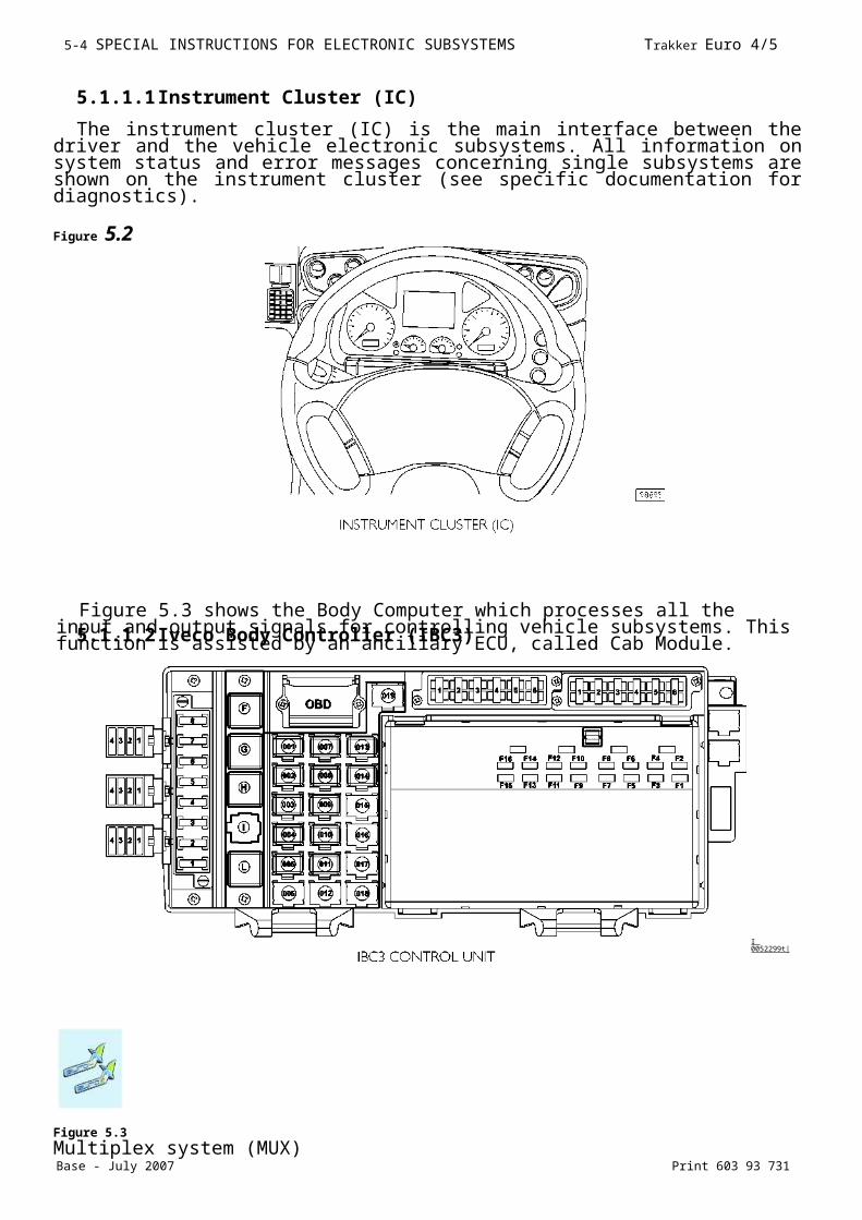
5.1.1.1 Instrument Cluster (IC)
The instrument cluster (IC) is the main interface between the driver and the vehicle electronic subsystems. All information on system status and error messages concerning single subsystems are shown on the instrument cluster (see specific documentation for diagnostics).
Figure 5.2
5.1.1.2 Iveco Body Controller (IBC3)
Figure 5.3
Multiplex system (MUX)
Figure 5.3 shows the Body Computer which processes all the input and output signals for controlling vehicle subsystems. This function is assisted by an ancillary ECU, called Cab Module.
I 0052299t|
Base - July 2007 Print 603 93 731
5-4 SPECIAL INSTRUCTIONS FOR ELECTRONIC SUBSYSTEMS Trakker Euro 4/5
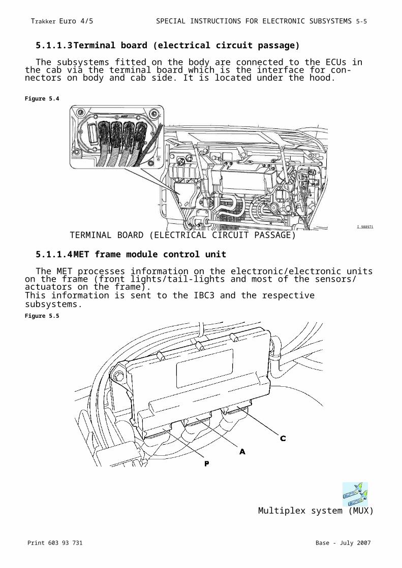
5.1.1.3 Terminal board (electrical circuit passage)
The subsystems fitted on the body are connected to the ECUs in the cab via the terminal board which is the interface for connectors on body and cab side. It is located under the hood.
Figure 5.4
I 988971
5.1.1.4 MET frame module control unit
The MET processes information on the electronic/electronic units on the frame (front lights/tail-lights and most of the sensors/ actuators on the frame).This information is sent to the IBC3 and the respective subsystems.Figure 5.5
Multiplex system (MUX)
TERMINAL BOARD (ELECTRICAL CIRCUIT PASSAGE)

Print 603 93 731 Base - July 2007
Trakker Euro 4/5 SPECIAL INSTRUCTIONS FOR ELECTRONIC SUBSYSTEMS 5-5
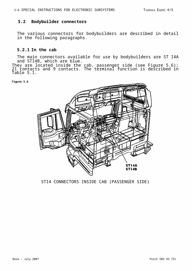
5.2 Bodybuilder connectors
The various connectors for bodybuilders are described in detail in the following paragraphs.
5.2.1 In the cab
The main connectors available for use by bodybuilders are ST I4A and STI4B, which are blue.
They are located inside the cab, passenger side (see Figure 5.6); 21 contacts and 9 contacts. The terminal function is described in Table 5.1.
Figure 5.6
STI4 CONNECTORS INSIDE CAB (PASSENGER SIDE)
Base - July 2007 Print 603 93 731
5-6 SPECIAL INSTRUCTIONS FOR ELECTRONIC SUBSYSTEMS Trakker Euro 4/5
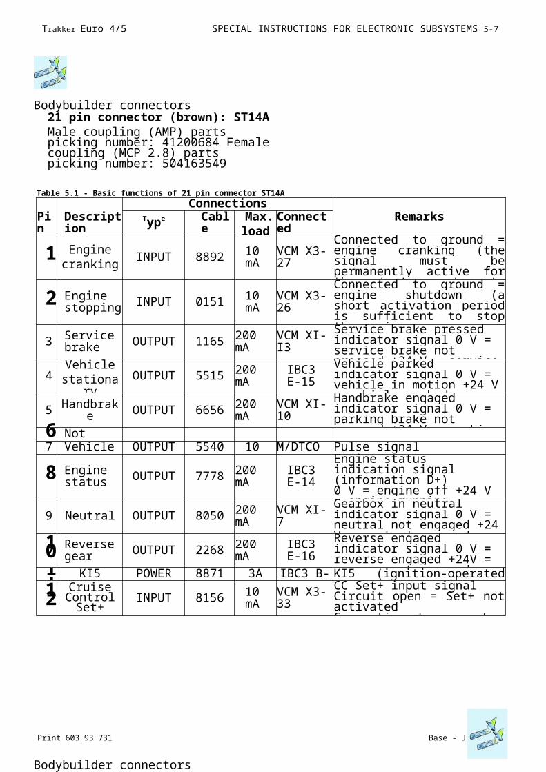
Bodybuilder connectors21 pin connector (brown): ST14AMale coupling (AMP) parts picking number: 41200684 Female coupling (MCP 2.8) parts picking number: 504163549
Bodybuilder connectors
Table 5.1 - Basic functions of 21 pin connector ST14A
ConnectionsPin
Description
Type Cable
Max.
Connected
Remarks
1 Enginecranking
INPUT 8892 10 mA
VCM X3-27
Connected to ground = engine cranking (the signal must be permanently active for the starter motor to turn)Open circuit = no action
2 Engine stopping INPUT 0151 10
mAVCM X3-26
Connected to ground = engine shutdown (a short activation period is sufficient to stop the engineOpen circuit = no action
3 Service brake OUTPUT 1165 200
mA VCM XI-I3Service brake pressed indicator signal 0 V = service brake not pressed +24 V = service brake pressed
4Vehicle
stationaryOUTPUT 5515 200
mAIBC3 E-15
Vehicle parked indicator signal 0 V = vehicle in motion +24 V = vehicle parked
5 Handbrake OUTPUT 6656 200 mA
VCM XI-10
Handbrake engaged indicator signal 0 V = parking brake not engaged +24 V = parking brake engaged6 Not
connected7 Vehicle speed
OUTPUT 5540 10 mA
M/DTCO B7
Pulse signal
8 Engine status OUTPUT 7778 200
mAIBC3 E-14
Engine status indication signal (information D+)0 V = engine off +24 V = engine running
9 Neutral OUTPUT 8050 200 mA VCM XI-7
Gearbox in neutral indicator signal 0 V = neutral not engaged +24 V = neutral engaged10 Reverse
gear OUTPUT 2268 200 mA
IBC3 E-16
Reverse engaged indicator signal 0 V = reverse engaged +24V = reverse not engaged11 KI5 POWER 8871 3A IBC3 B-I KI5 (ignition-operated power point)12
Cruise Control Set+
INPUT 8156 10 mA
VCM X3-33
CC Set+ input signalCircuit open = Set+ not activatedConnection to ground = Set+
Base - July 2007 Print 603 93 731
5-7 SPECIAL INSTRUCTIONS FOR ELECTRONIC SUBSYSTEMS Trakker Euro 4/5
ConnectionsPin
Description
Type Cable
Max.
Connected
Remarks
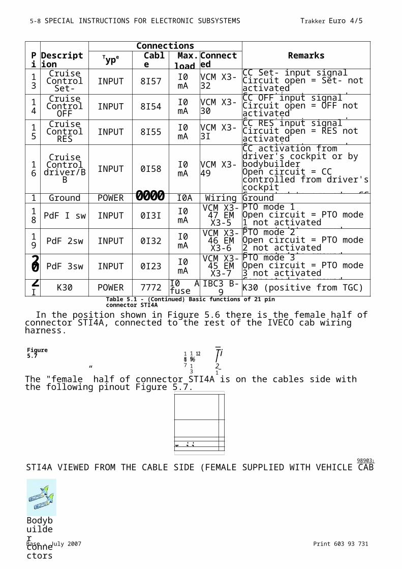
13
Cruise Control
Set-INPUT 8I57 I0
mAVCM X3-32
CC Set- input signalCircuit open = Set- not activatedConnection to ground = Set-
14
Cruise Control
OFFINPUT 8I54 I0
mAVCM X3-30
CC OFF input signalCircuit open = OFF not activatedConnection to ground = OFF
15
Cruise Control
RESINPUT 8I55 I0
mAVCM X3-3I
CC RES input signalCircuit open = RES not activatedConnection to ground = RES
16
Cruise Control
driver/BBINPUT 0I58 I0
mAVCM X3-49
CC activation from driver's cockpit or by bodybuilderOpen circuit = CC controlled from driver's cockpitConnected to ground = CC controlled by bodybuilder (BB)
17
Ground POWER 0000 I0A Wiring Ground
18 PdF I sw INPUT 0I3I I0
mA
VCM X3-47 EM X3-
5
PTO mode 1Open circuit = PTO mode 1 not activated Connected to ground = PTO mode 1 activated
19 PdF 2sw INPUT 0I32 I0
mA
VCM X3-46 EM X3-
6
PTO mode 2Open circuit = PTO mode 2 not activated Connected to ground = PTO mode 2 activated20 PdF 3sw INPUT 0I23 I0
mA
VCM X3-45 EM X3-
7
PTO mode 3Open circuit = PTO mode 3 not activated Connected to ground = PTO mode 3 activated2
IK30 POWER 7772 I0 A
fuse IBC3 B-9 K30 (positive from TGC)
In the position shown in Figure 5.6 there is the female half of connector STI4A, connected to the rest of the IVECO cab wiring harness.
The "female” half of connector STI4A is on the cables side with the following pinout Figure 5.7.
98903 ]
STI4A VIEWED FROM THE CABLE SIDE (FEMALE SUPPLIED WITH VEHICLE CAB WIRING
Figure 5.7 1
815
1217
%13
—Til2_1
Bodybuilder connectors
Table 5.1 - (Continued) Basic functions of 21 pin connector STI4A
r i i
Base - July 2007 Print 603 93 731
5- 8 SPECIAL INSTRUCTIONS FOR ELECTRONIC SUBSYSTEMS Trakker Euro 4/5
HARNESS)
Print 603 93 731 Base - July 2007
Trakker Euro 4/5 SPECIAL INSTRUCTIONS FOR ELECTRONIC SUBSYSTEMS 5-9
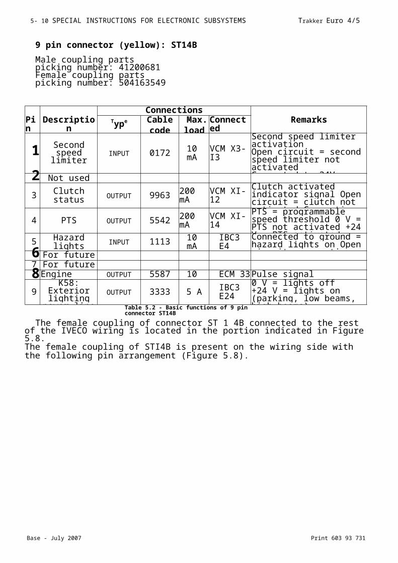
9 pin connector (yellow): ST14B
Male coupling parts picking number: 41200681 Female coupling parts picking number: 504163549
ConnectionsPin
Description Type Cablecode
Max.
Connected
Remarks
1Second speed limiter INPUT 0172 10
mAVCM X3-I3
Second speed limiter activationOpen circuit = second speed limiter notactivatedConnected to 24V = second 2 Not used
3 Clutch status OUTPUT 9963 200 mA
VCM XI-12
Clutch activated indicator signal Open circuit = clutch not activated Connection to ground = clutch activated
4 PTS OUTPUT 5542 200 mA
VCM XI-14
PTS = programmable speed threshold 0 V = PTS not activated +24 V = PTS activated
5 Hazard lights INPUT 1113 10 mA IBC3 E4
Connected to ground = hazard lights on Open circuit = no action6 For future
use7 For future use8Engine speed
signalOUTPUT 5587 10
mAECM 33 Pulse signal
9K58: Exterior
lighting power line
OUTPUT 3333 5 A IBC3 E24
0 V = lights off+24 V = lights on (parking, low beams, high beams)
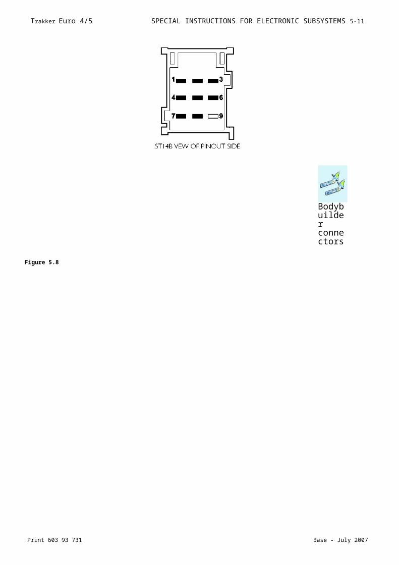
The female coupling of connector ST 1 4B connected to the rest of the IVECO wiring is located in the portion indicated in Figure 5.8.The female coupling of STI4B is present on the wiring side with the following pin arrangement (Figure 5.8).
Table 5.2 - Basic functions of 9 pin connector ST14B
Base - July 2007 Print 603 93 731
5- 10 SPECIAL INSTRUCTIONS FOR ELECTRONIC SUBSYSTEMS Trakker Euro 4/5
Figure 5.8
Bodybuilder connectors

Print 603 93 731 Base - July 2007
Trakker Euro 4/5 SPECIAL INSTRUCTIONS FOR ELECTRONIC SUBSYSTEMS 5-11
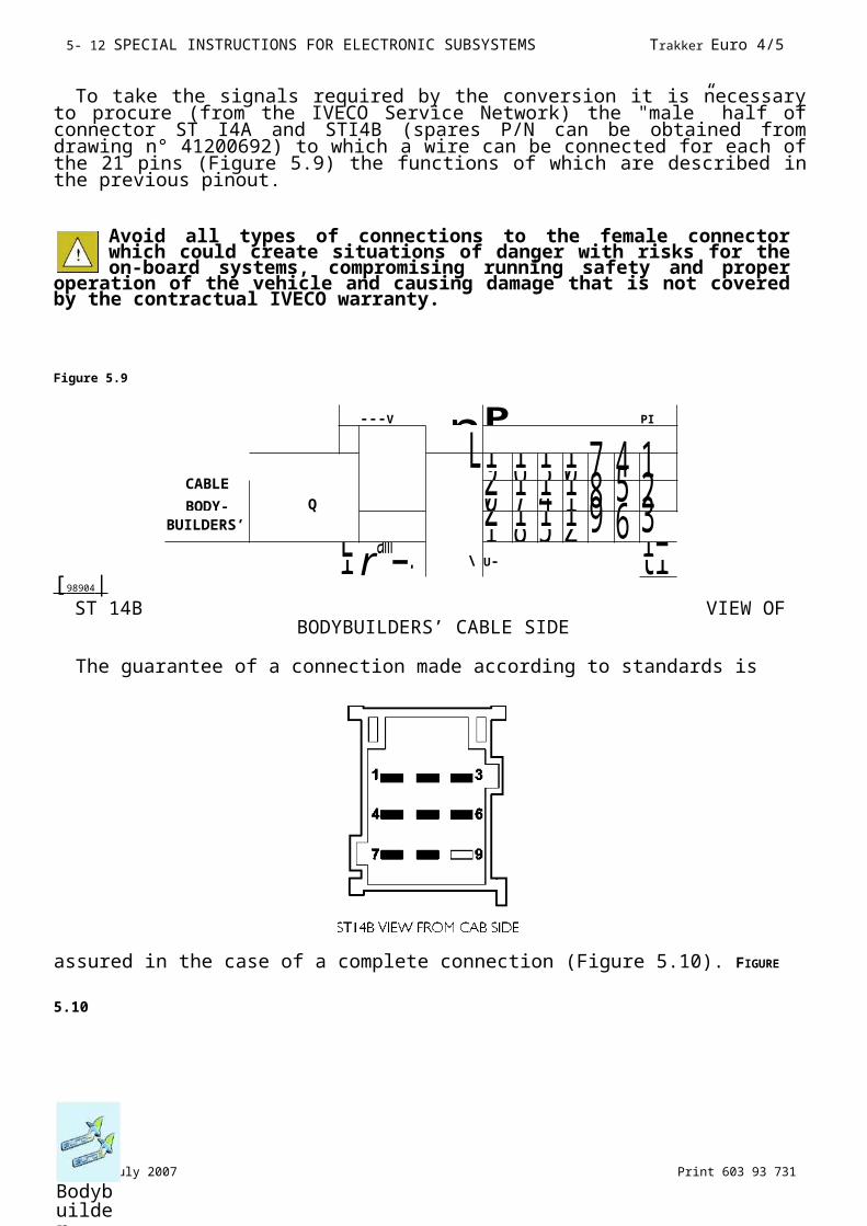
To take the signals required by the conversion it is necessary to procure (from the IVECO Service Network) the "male” half of connector ST I4A and STI4B (spares P/N can be obtained from drawing n° 41200692) to which a wire can be connected for each of the 21 pins (Figure 5.9) the functions of which are described in the previous pinout.
Avoid all types of connections to the female connector which could create situations of danger with risks for the on-board systems, compromising running safety and proper operation of
the vehicle and causing damage that is not covered by the contractual IVECO warranty.
Figure 5.9
[ 98904 | ST 14B VIEW OF
BODYBUILDERS’ CABLE SIDE
The guarantee of a connection made according to standards is assured in the case
of a complete connection (Figure 5.10). FIGURE 5.10
----V n P PI
L19 16 13 10 7 4 1CABLE
BODY- Q20 17 14 11 8 5 2
BUILDERS’
21 18 15 12 9 6 3Li ram\J U-
1=tl
Bodybuilder connectors
Print 603 93 731 Base - July 2007
Trakker Euro 4/5 SPECIAL INSTRUCTIONS FOR ELECTRONIC SUBSYSTEMS 5-1 1
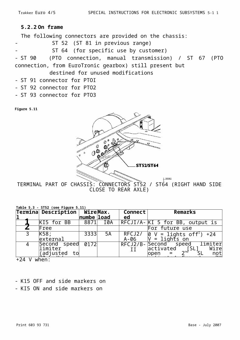
5.2.2 On frame
The following connectors are provided on the chassis:- ST 52 (ST 81 in previous range)
- ST 64 (for specific use by customer)
- ST 90 (PTO connection, manual transmission) / ST 67 (PTO connection, from
EuroTronic gearbox) still present but
destined for unused modifications
- ST 91 connector for PTOI
- ST 92 connector for PTO2
- ST 93 connector for PTO3
Figure 5.11
TERMINAL PART OF CHASSIS: CONNECTORS ST52 / ST64 (RIGHT HAND SIDE CLOSE TO REAR AXLE)
- K15 OFF and side markers on
- KI5 ON and side markers on
I 98902 I
Table 5.3 - ST52 (see Figure 5.11)
Terminal
Description Wire
Max. load
Connected
Remarks
1 KI5 for BB 8871 I0A RFCJI/A-2 KI 5 for BB, output is short-circuit protected2 Free For future use
3 K58; external lights
3333 5A RFCJ2/A-06
0 V = lights offI) +24 V = lights on
4 Second speed limiter (adjusted to 30 km/h)
0172 RFCJ2/B- II Second speed limiter activated [SL] Wire open = 2nd
SL not activated Ground = 2nd
SL active+24 V when:
Print 603 93 731 Base - July 2007
Trakker Euro 4/5 SPECIAL INSTRUCTIONS FOR ELECTRONIC SUBSYSTEMS 5-1 1
- K15 ON and lights on (dipped beam and main beam)
Bodybuilder connectors
Base - July 2007 Print 603 93 731
5- 12 SPECIAL INSTRUCTIONS FOR ELECTRONIC SUBSYSTEMS Trakker Euro 4/5
Table 5.4 - ST64 (see Figure 5.11)
5-pin connector
Bodybuilder connectors
For general use by bodybuilders: four terminals in the 15-pole connector can be used for the trailer (72010).Terminal
Description Circuit
Connected to (Source/Destinatio
n)
Circuit description
1 - 8021 terminal 15, 72010 15-pole power, terminal pin 102 - 7021 terminal 14, 72010 1 5-pole power, terminal pin 1 23 - 6021 terminal 10, 72010 15-pole power, terminal pin 144 KI5 8075 ST52/I E RFC JI/A02
5 - 8075 terminal II, 72010 1 5-pole power, terminal pin 1 1
Table 5.5 - ST9I (right-hand side near transmission, see Figure 5.12)
Terminal
Description Wire
Max. load
Connected
Remarks
I PTO counter-reaction
6I3I EM X3-8 PTO feedback signalWire open = PTO not engagedGround = PTO engaged2 PTO control 9I3I 1,6 A EM XI-I For electrical PTO activation 0 V = solenoid valve not activated +24 V = solenoid valve activated3 PTO
enablement039I EM X3-I I PTO sensor may be
disabled/may be disabled Wire open = PTO not engaged Ground = PTO engaged4 Ground 0000 II A Ground (ground to middle of chassis)h Two input conditions can be detected:
Condition 1 = Wire openCondition 2 =GroundActive signal condition selected via EASYUsed only for pressure switch detection with Multipower PTO and Engine PTO.Can be used as additional digital input for other applications managed by MUX PTO control.
Print 603 93 731 Base - July 2007
Trakker Euro 4/5 SPECIAL INSTRUCTIONS FOR ELECTRONIC SUBSYSTEMS 5- 1 13
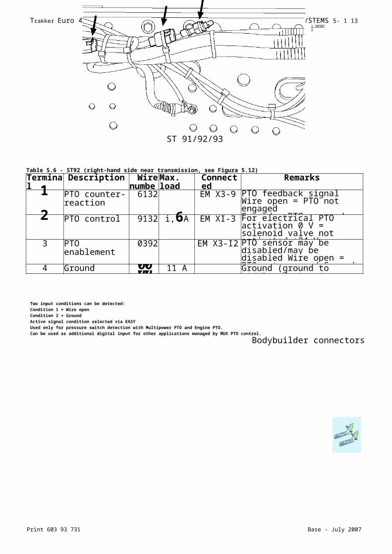
ST 91/92/93
Two input conditions can be detected:Condition 1 = Wire openCondition 2 = GroundActive signal condition selected via EASYUsed only for pressure switch detection with Multipower PTO and Engine PTO.Can be used as additional digital input for other applications managed by MUX PTO control.
Bodybuilder connectors
I 98907 I
Table 5.6 - ST92 (right-hand side near transmission, see Figura 5.12)
Terminal
Description Wire
Max. load
Connected
Remarks
1 PTO counter-reaction
6132 EM X3-9 PTO feedback signalWire open = PTO not engagedGround = PTO engaged2 PTO control 9132 i,6A EM XI-3 For electrical PTO activation 0 V = solenoid valve not activated +24 V = solenoid valve activated3 PTO
enablement0392 EM X3-I2 PTO sensor may be
disabled/may be disabled Wire open = PTO not engaged Ground = PTO engaged4 Ground 0000 11 A Ground (ground to middle of chassis)

Base - July 2007 Print 603 93 731
5-14 SPECIAL INSTRUCTIONS FOR ELECTRONIC SUBSYSTEMS Trakker Euro 4/5
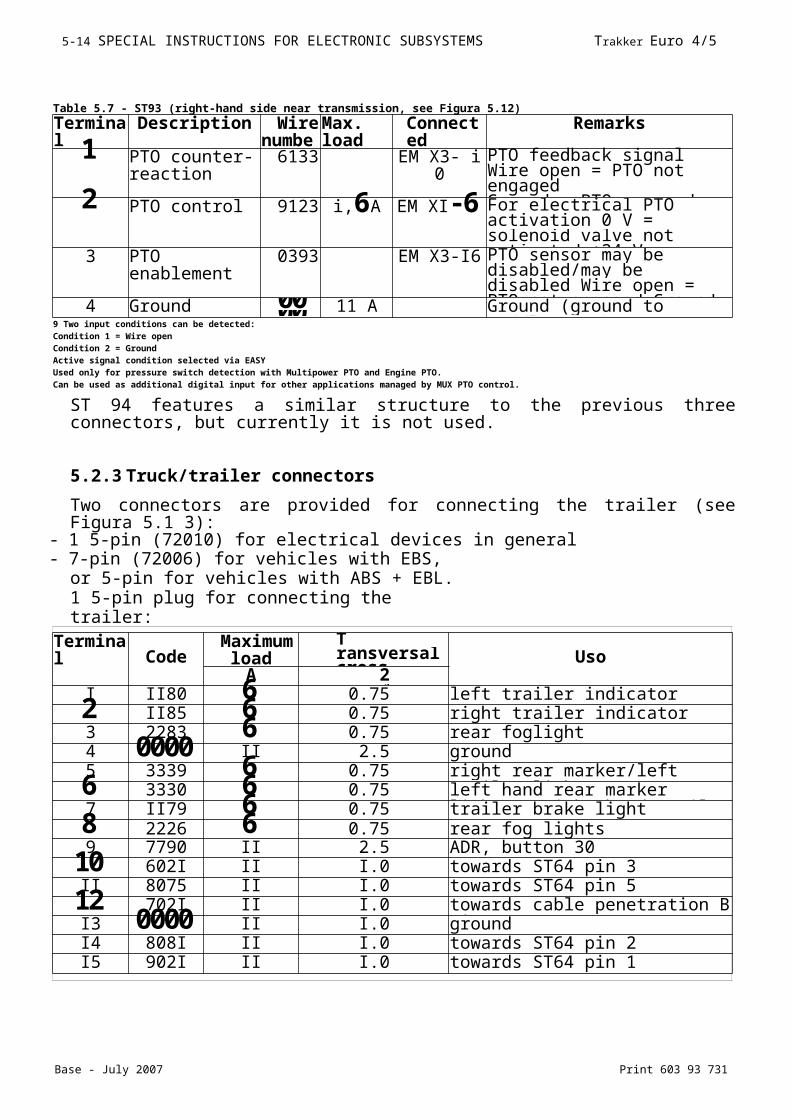
ST 94 features a similar structure to the previous three connectors, but currently it is not used.
5.2.3 Truck/trailer connectors
Two connectors are provided for connecting the trailer (see Figura 5.1 3):- 1 5-pin (72010) for electrical devices in general
- 7-pin (72006) for vehicles with EBS, or 5-pin for vehicles with ABS + EBL. 1 5-pin plug for connecting the trailer:
Bodybuilder connectors
Table 5.7 - ST93 (right-hand side near transmission, see Figura 5.12)
Terminal
Description Wire
Max. load
Connected
Remarks
1 PTO counter-reaction
6133 EM X3- i 0 PTO feedback signalWire open = PTO not engagedGround = PTO engaged2 PTO control 9123 i,6A EM XI-6 For electrical PTO activation 0 V = solenoid valve not activated +24 V = solenoid valve activated3 PTO
enablement0393 EM X3-I6 PTO sensor may be
disabled/may be disabled Wire open = PTO not engaged Ground = PTO engaged4 Ground 0000 11 A Ground (ground to middle of chassis)9 Two input conditions can be detected:
Condition 1 = Wire openCondition 2 = GroundActive signal condition selected via EASYUsed only for pressure switch detection with Multipower PTO and Engine PTO.Can be used as additional digital input for other applications managed by MUX PTO control.
Terminal Code
Maximum
T ransversal cross-
UsoA 2
mm2I II80 6 0.75 left trailer indicator2 II85 6 0.75 right trailer indicator3 2283 6 0.75 rear foglight4 0000 II 2.5 ground5 3339 6 0.75 right rear marker/left trailer light6 3330 6 0.75 left hand rear marker lights / right
hand trailer light7 II79 6 0.75 trailer brake light8 2226 6 0.75 rear fog lights9 7790 II 2.5 ADR, button 30
10 602I II I.0 towards ST64 pin 3II 8075 II I.0 towards ST64 pin 5
12 702I II I.0 towards cable penetration B pin 19I3 0000 II I.0 groundI4 808I II I.0 towards ST64 pin 2I5 902I II I.0 towards ST64 pin 1
Print 603 93 731 Base - July 2007
Trakker Euro 4/5 SPECIAL INSTRUCTIONS FOR ELECTRONIC SUBSYSTEMS 5- 1 15
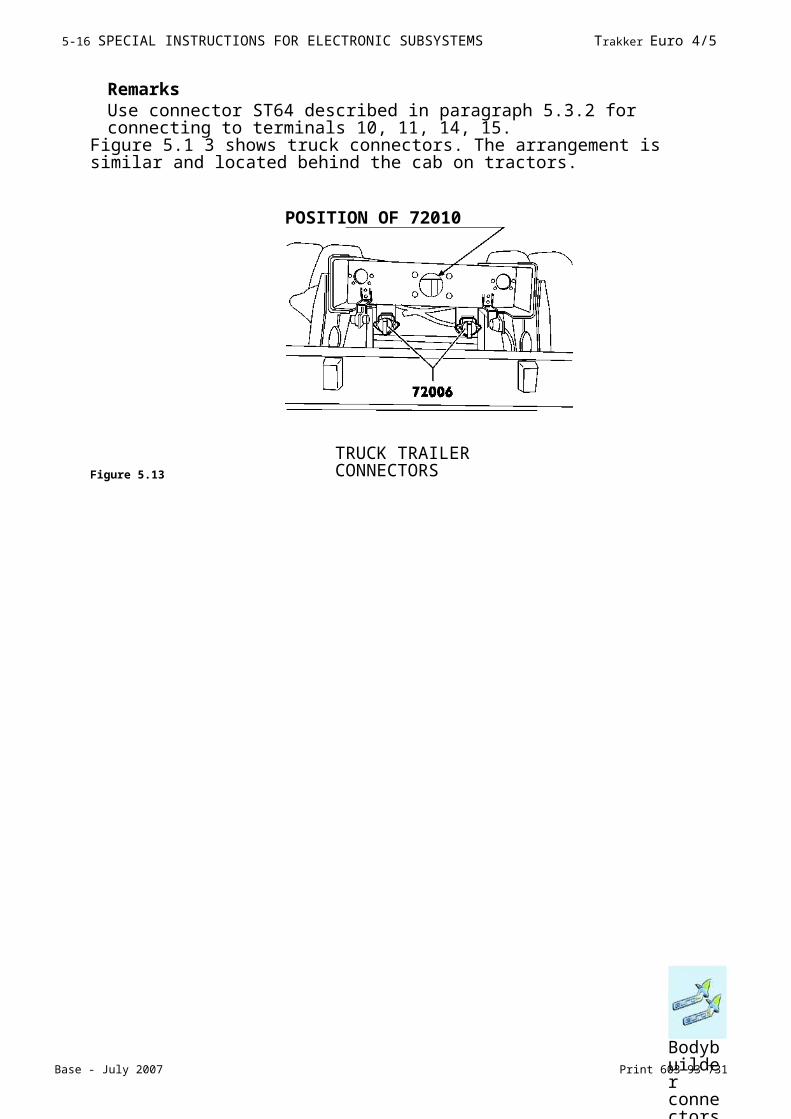
RemarksUse connector ST64 described in paragraph 5.3.2 for connecting to terminals 10, 11, 14, 15.
Figure 5.1 3 shows truck connectors. The arrangement is similar and located behind the cab on tractors.
Figure 5.13
POSITION OF 72010
TRUCK TRAILER CONNECTORS
Bodybuilder connectors
Base - July 2007 Print 603 93 731
5- 1 6 SPECIAL INSTRUCTIONS FOR ELECTRONIC SUBSYSTEMS Trakker Euro 4/5
5.3 Electrical circuit modifications
CAN line wires and electric/electronic devices must not be modified.IVECO recommends not to change the other electrical circuits and wiring harnesses either. Any modifications on the system will reduce quality and safety characteristics. Bodybuilders
must use genuine IVECO spare parts if changes to the electrical system are inevitable. IVECO cannot be liable for system malfunctioning following the instructions contained in this chapter.
5.3.1 Introduction
The instructions provided by IVECO in paragraph 2.1.1 also referto Multiplex system wiring harnesses. IVECO connectors and the respective terminals cannot be modified. Avoid connecting and disconnecting the chassis ECU connectors for more than three times to prevent damaging the gel which ensures tightness of the connections.
5.3.2 Wiring harness length
In Trakker, the MUX CAN line and the traditional electrical wires form a single wiring harness. Consequently, it is not possible to replace only the CAN line or the electrical wiring where the electrical system is formed by both types of wires.The wire length (CAN line + electrical wires) may not be correct when repositioning ECUs connected to the Multiplex system.- excessive- not sufficientIf the length is excessive, fold the wires without forming rings (this could cause undesired electromagnetic effects). Preferably use figures of 8. The wire which connects the ECUs is very stiff. For this reason, it must be replaced when it cannot be folded. Replace the wiring if the length is not sufficient. Use genuine IVECO spare parts (contact the IVECO service network).The wire length depends on three factors: wheelbase, overhang and crossmember position. Select one of the variants in the table for replacing the wiring if the modification involves a wheelbase/overhang which already exists in the IVECO range or, conversely, choose the closest variant for the solution (the table only shows the currently produced wheelbase/overhang combinations).
In all cases, the CAN wiring itself cannot be changed. All modifications are expressly forbidden by IVECO.
I
Base - July 2007 Print 603 93 731
5- 1 6 SPECIAL INSTRUCTIONS FOR ELECTRONIC SUBSYSTEMS Trakker Euro 4/5
Electrical circuit modifications
Electrical circuit modifications
Electrical circuit modifications
This does not refer to modifications which do not involve the Multiplex wiring (CAN line + electrical wires). For example, when extending the overhang without changing the position of the RFC, simply replace the electrical wires leading from the RFC to the respective utilities.
IVECO recommends replacing traditional electrical wires with genuine components instead of modifying them.Contact IVECO for particularly difficult cases. Send a diagram with the chassis dimensions and the new ECU positions.
5.3.3 Repositioning ECUs
IVECO recommends to avoid modifications which entails moving ECUs. Follow the instructions below if repositioning ECUs is unavoidable:
- ECUs must be positioned on the chassis or in the cab and secured with a fastening similar to the original one (i.e. bracket). To avoid malfunctions, the ECU in the chassis must not be turned (e.g. to avoid water ingress). Consequently, the original orientation must be preserved.
Table 5.9
variant ID number05 4124 2363 KZ 50-833004 4124 2362 KZ 50-833003 4124 2361 KZ 50-8333002 4124 2367 KZ 50-833001 4124 2359 KZ 50-8330
Table 5.10
variant ID number11 4 24 2415 KZ 50-833010 4 24 2425 KZ 50-833009 4 24 2422 KZ 50-83330
08 4 24 2420 KZ 50-833007 4 24 2417 KZ 50-8330
06 4 24 2391 KZ 50-833005 4 24 2389 KZ 50-833004 4 24 2386 KZ 50-833003 4 24 2383 KZ 50-8333002 4 24 2380 KZ 50-833001 4 24 2376 KZ 50-8330

Base - July 2007 Print 603 93 731
5- 1 6 SPECIAL INSTRUCTIONS FOR ELECTRONIC SUBSYSTEMS Trakker Euro 4/5
- ECUs must not be fitted on the subframe;- the cover must always be refitted;- avoid subjecting ECUs to knocks from debris and stones from the road when travelling.
Electrical circuit modifications
Base - July 2007 Print 603 93 731
5- 1 6 SPECIAL INSTRUCTIONS FOR ELECTRONIC SUBSYSTEMS Trakker Euro 4/5
5.3.4 Disconnecting ECUs
Operations which do not comply with the instructions specified by IVECO or made by non qualified personnel can cause severe damage to on-board systems, effect driving safety and correct
operation of the vehicle and cause considerable damage which is not covered by warranty.
Follow the instructions below carefully before disconnecting an ECU:- turn the ignition key to off, if it is inserted;- switch off the additional heaters and wait for the end of the cooling down cycle (the warning light in the button will go out);- turn on the map reading lights located in the middle of the header rail;
- open the TGC (master switch), where fitted, with the switch arranged in the cab. The map reading lights will go out when the circuit breaker is open;
- isolate the battery by disconnecting the battery cables: disconnect the negative terminal first followed by the positive terminal;- disconnect the ECU.Electrical circuit modifications
Print 603 93 731 Base - July 2007
Trakker Euro 4/5 SPECIAL INSTRUCTIONS FOR ELECTRONIC SUBSYSTEMS 5-2 1
5.4 FMS
The fleet management systems are integrated in the VCM.The data, transmitted according to the FMS standard (visit www.fms-standards.com), can be acquired in real time by an on-board computer.As a result of processing the data, it is possible:- to obtain information about the operating conditions of the vehicle (times, distances, fuel consumption, etc.);- analyse the operating conditions of the engine and the use of the braking system;- analyse the distribution of the distances travelled, speed, frequency of stops and
starts.The installation of the on-board computer, hardware and software for data processing and management is the task of the ICT installer.
CAN connector for onboard PC wiring
The CAN connection on board the vehicle (ST40) is of the 6 way JUNIOR POWER TIMER HOUSING - AMP ORDER- NO 1- 965640-1 type.The wiring connectorto the onboard PC (see Figure 5.14) must be 6 way_AMP TAB HOUSING, 2.8 mm - AMP ORDER- NO 1 - 965641 -1 mating connector (use contact type Junior Power Timer - P/N 962882-1 or 962882-2).
Figure 5.14
The pin function is shown in the following table:
Pin 5 (Ground) must not be used unless required by the onboard computer.The VDI must be connected to the computer via the CAN line. The specifications are
I 989121
FMS
Table 5.11 - Connector ST40/02 pins
Pin DescriptionT Reserved for future IVECO use2 CAN_H (white wire in vehicle wiring harness)3 CAN_L (green wire in vehicle wiring harness)4 Reserved for future IVECO use5 Ground6 Not used
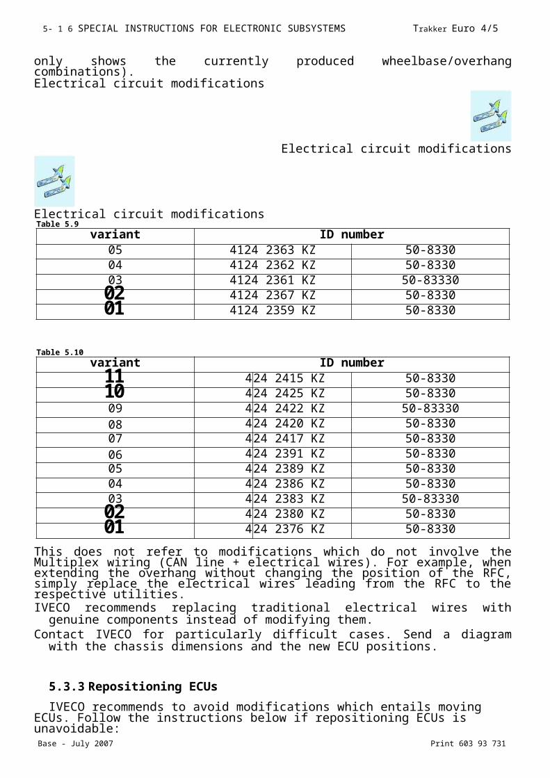
Print 603 93 731 Base - July 2007
Trakker Euro 4/5 SPECIAL INSTRUCTIONS FOR ELECTRONIC SUBSYSTEMS 5-2 1
shown in Table 5.12.Onboard computer installation, wiring downstream of the connector ST40/2,
hardware and software for managing and processing data is the responsibility of the bodybuilder.Information on computerised system installers who are qualified by IVECO can be
found at IVECO Dealers.
NOTE Information provided by VDI includes the message ”FMS standard interface” which identifies the standard revision supported by the VDI interface fitted on the vehicle. A VDI prior to FMS standard implementation is fitted if the message is not present. All functions illustrated in this paragraph will equally be available in this case.
Print 603 93 731 Base - July 2007
Trakker Euro 4/5 SPECIAL INSTRUCTIONS FOR ELECTRONIC SUBSYSTEMS 5-2 1
FMS
Print 603 93 731 Base - July 2007
Trakker Euro 4/5 SPECIAL INSTRUCTIONS FOR -SCR- EXHAUST SYSTEMS 6- 1
SECTION 6
Special instructions for -SCR- exhaust system
Page
Index
Index
6.1 General specifications 6-36.2 The nitrogen oxide catalytic reduction principle. AdBlue 6-4
6.3 On-board instruments 6-76.4 Distribution of the ecological additive AdBlue 6-86.5 Specifications for installation and removal 6-96.5.1 Operations for positioning the AdBlue tank 6-96.5.2 Operations on AdBlue pipes and heating water 6-126.5.3 Altering the supply module position 6-156.5.4 Operations on the dosing module 6-166.5.5 Operations on exhaust pipes 6-17
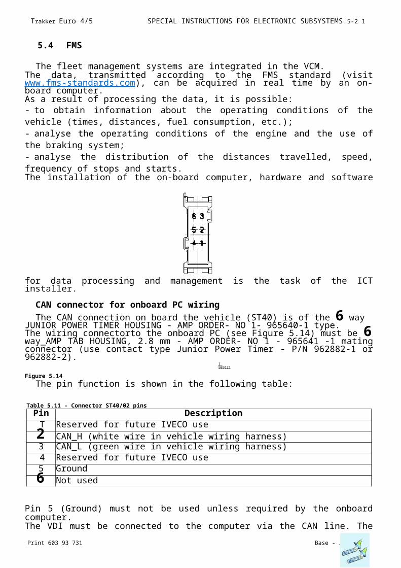
Base - July 2007 Print 603 93 731
6-2 SPECIAL INSTRUCTIONS FOR -SCR- EXHAUST SYSTEMS Trakker Euro 4/5
6.1 General specifications
This chapter contains important information on the -SCR- exhaust systemS fitted on the IVECO series (EuroCargo - Stralis - Trakker).In order to comply with Euro4 Euro5 standards, IVECO has chosen the SCR (selective catalyst reduction) system to reduce the nitrogen oxide (NOx) emissions produced by exhaust gas.SCR is an exhaust gas post-treatment system that uses a catalyzer which, by means of a chemical reaction, transforms NOx nitrogen oxyde into nitrogen and water. This chemical reaction is produced by an additive called AdBlue (a solution of urea + water).
Figure 6.1
Coolant
AdBlue
I 1174731
1. Pumping module - 2. Urea tank - 3. Catalyzer - 4. Dosing module
Print 603 93 731 Base - July 2007
Trakker Euro 4/5 SPECIAL INSTRUCTIONS FOR -SCR- EXHAUST SYSTEMS 6-3
General specifications

Base - July 2007 Print 603 93 731The nitrogen oxide catalytic reduction principle. AdBlue
6-4 SPECIAL INSTRUCTIONS FOR -SCR- EXHAUST SYSTEMS Trakker Euro 4/5
6.2 The nitrogen oxide catalytic reduction principle. AdBlue
The additive is sent from a dedicated reservoir by means of supply module (1) to dosing module (3), which injects AdBlue into the exhaust pipe.The mixture thus obtained is then fed to the SCR catalyzer that transforms the NOx into nitrogen and water.Post-treatment is based on a simple principle: the chemical reaction of ammonia NH3 with nitrogen oxides NO and NO2 produces two harmless substances: water vapour H2O and nitrogen N2.The whole system is managed by an electronic control unit.
Figure 6.2
1. Pumping module - 2. Catalyzer - 3. Dosing module - 4. AdBlue reservoir
Print 603 93 731 Base - July 2007The nitrogen oxide catalytic reduction principle. AdBlue
Trakker Euro 4/5 SPECIAL INSTRUCTIONS FOR -SCR- EXHAUST SYSTEMS 6-5
Main system components Pump module
Figure 6.3
Dosing module
Figure 6.4
1. Ad Blue inlet - 2. Electrical
connection - 3. Ad Blue outlet Its task is to meter the Ad
1. Ad Blue return Pipe to the tank - 2. Ad Blue return Pipe
from Dosing module - 3. Ad Blue solution outlet ■ 4. Ad Blue solution inlet - 5. Electrical
connection - 6 . DCU control unit - 7. Filter - 8 . Pre-filter.
I 1081281
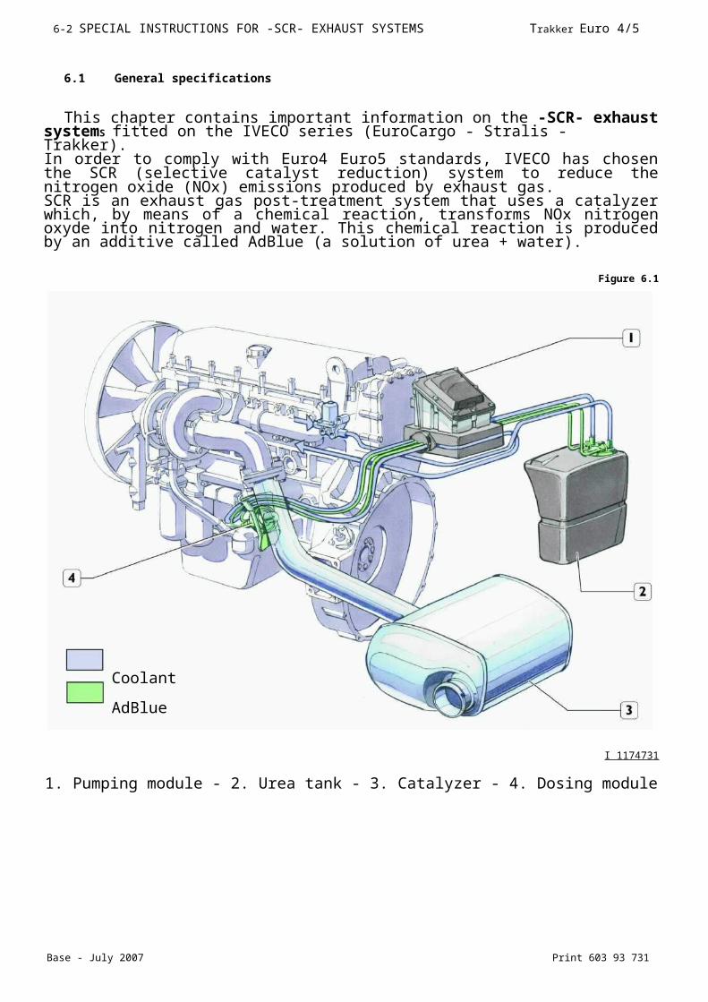
Base - July 2007 Print 603 93 731The nitrogen oxide catalytic reduction principle. AdBlue
6-6 SPECIAL INSTRUCTIONS FOR -SCR- EXHAUST SYSTEMS Trakker Euro 4/5
Blue solution sent to the exhaust pipe upstream of catalyst.

Print 603 93 731 Base - July 2007The nitrogen oxide catalytic reduction principle. AdBlue
Trakker Euro 4/5 SPECIAL INSTRUCTIONS FOR -SCR- EXHAUST SYSTEMS 6-7
Catalyzer
Figure 6.5
Catalyst (1), equipped with sound-proofing material, replaces the exhaust silencer.Inside the catalyst, the exhaust gas nitric oxides are, by reacting with ammonia, converted into free nitrogen and water vapour. Temperature sensors (2 and 3) and nitric oxide detecting sensor (4) are fitted onto catalyst (1).
AdBlue reservoirRemove nut (4) and dismantle elastic strap (3) securing tank (2). Sling tank (2) with
appropriate cable (5) and hook it to the hoister.
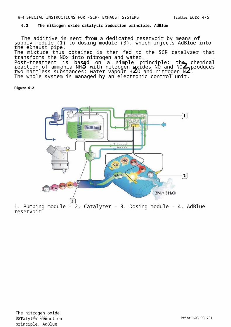
Trakker Euro 4/5 SPECIAL INSTRUCTIONS FOR -SCR- EXHAUST SYSTEMS 6-8
Print 603 93 731 Base - July 2007
6.3 On-board instruments
The on board diagnostic system checks the tank level continuously and informs the driver on the current quantity.
Figure 6.7
I 1167181
On-board instruments
6-9 SPECIAL INSTRUCTIONS FOR -SCR- EXHAUST SYSTEMS Trakker Euro 4/5
Base - July 2007 Print 603 93 731
6.4 Distribution of the ecological additive AdBlue
The 'AdBlue' denomination is recognized internationally; it is an aqueous solution consisting of high purity urea according to the DIN 70070 standard.It is absolutely safe, non-toxic and non-flammable.AdBlue manufacturers can assure the product direct distribution to the transporters with huge vehicle fleets, and the oil companies are also planning to install AdBlue pumps close to diesel fuel pumps within a short time.To ensure a capillary distribution and an adequate service level as of now, Iveco supplies AdBlue to its dealer network.
Figure 6.8
Figure 6.9 Figure 6.10
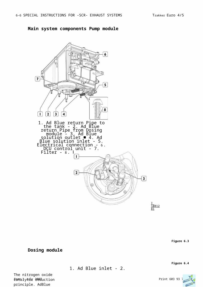
6-10 SPECIAL INSTRUCTIONS FOR -SCR- EXHAUST SYSTEMS Trakker Euro 4/5
Base - July 2007 Print 603 93 731
Distribution of the ecological additive AdBlue
Trakker Euro 4/5 SPECIAL INSTRUCTIONS FOR -SCR- EXHAUST SYSTEMS 6-11
Print 603 93 731 Base - July 2007Specifications for installation and removal
6.5 Specifications for installation and removal
The instructions that follow are intended forthe AdBlue injection system of the Bosch DENOX2 type, within the SCR system. If Bodybuilders make changes to the frame, the following procedures must be followed under all circumstances:
- disassembly: disconnect the hydraulic connectors first and then the electric connectors;- assembly: connect the electric connectors first and then the hydraulic connectors.
Compliance with this assembly/disassembly procedure will ensure that AdBlue does not come into contact with the electric connectors.
6.5.1 Operations for positioning the AdBlue tank
Figure 6.11
1 1 67201
As regards the AdBlue tank, ensure that:- the tank ventilation pipe is never closed;- the reservoir must contain at least 5 l of AdBlue at the end of each operation to ensure the dosing module is cooled;- after each operation, the tank does not contain more than 85% of AdBlue (corresponding to the max reading ofthe level sensor) with respect to the tank total volume, so as to guarantee enough room for AdBlue to expand during freezing at temperatures below -1 1 °C;
- The urea reservoir must be made out of plastic or stainless steel;- The reservoir and its float must not be separated.
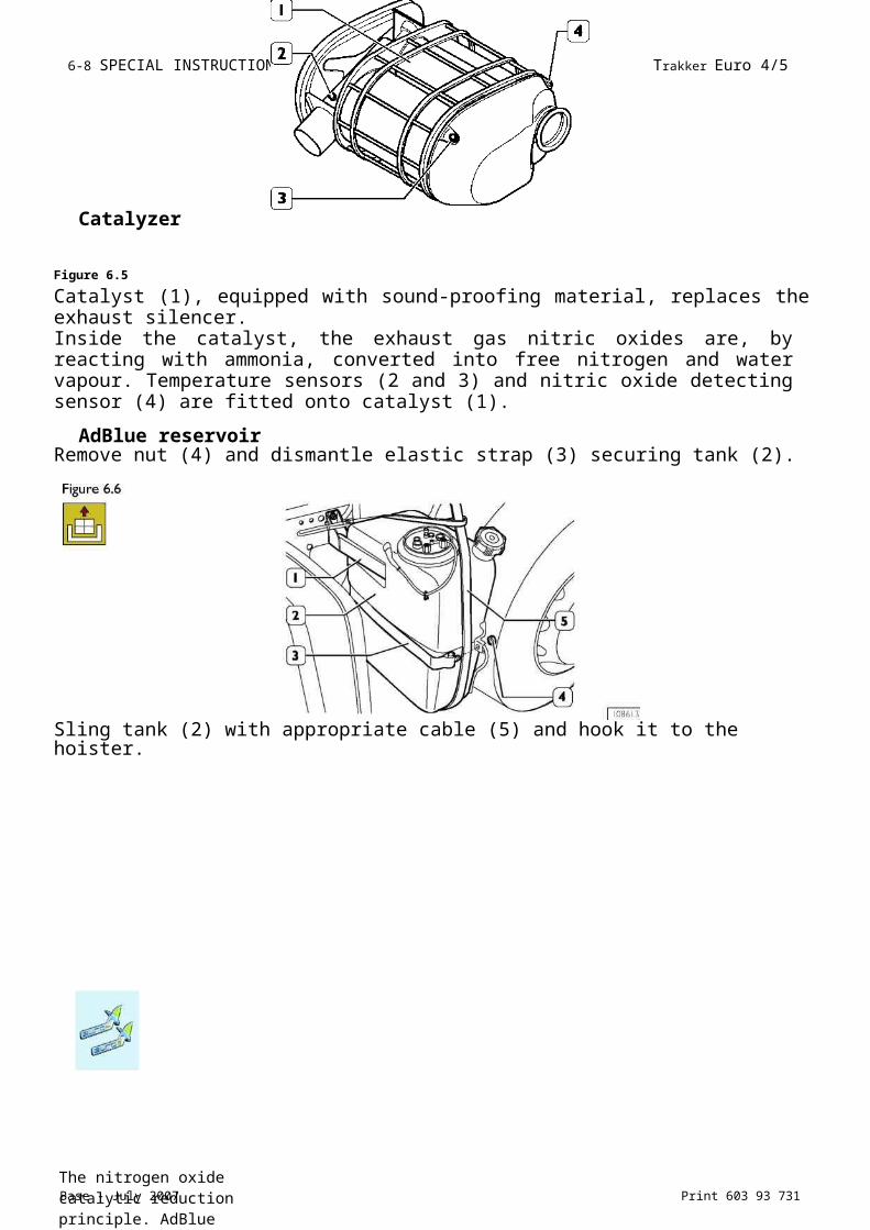
6- 12 SPECIAL INSTRUCTIONS FOR -SCR- EXHAUST SYSTEMS Trakker Euro 4/5
Base - July 2007 Print 603 93 731Specifications for installation and removal
when fitting equipment onto the chassis, there is enough room for the AdBlue fill gun (1, Figure 6.1 2) to fit completely and correctly into the tank filler.1. Cover - 2. Breather pipe - 3. AdBlue pipe - 4. Engine coolant pipe - 5. Electrical
connection - 6. AdBlue pipe -7. Engine cooling pipe - 8. Level gauge
Figure 6.13
a
I 1167591
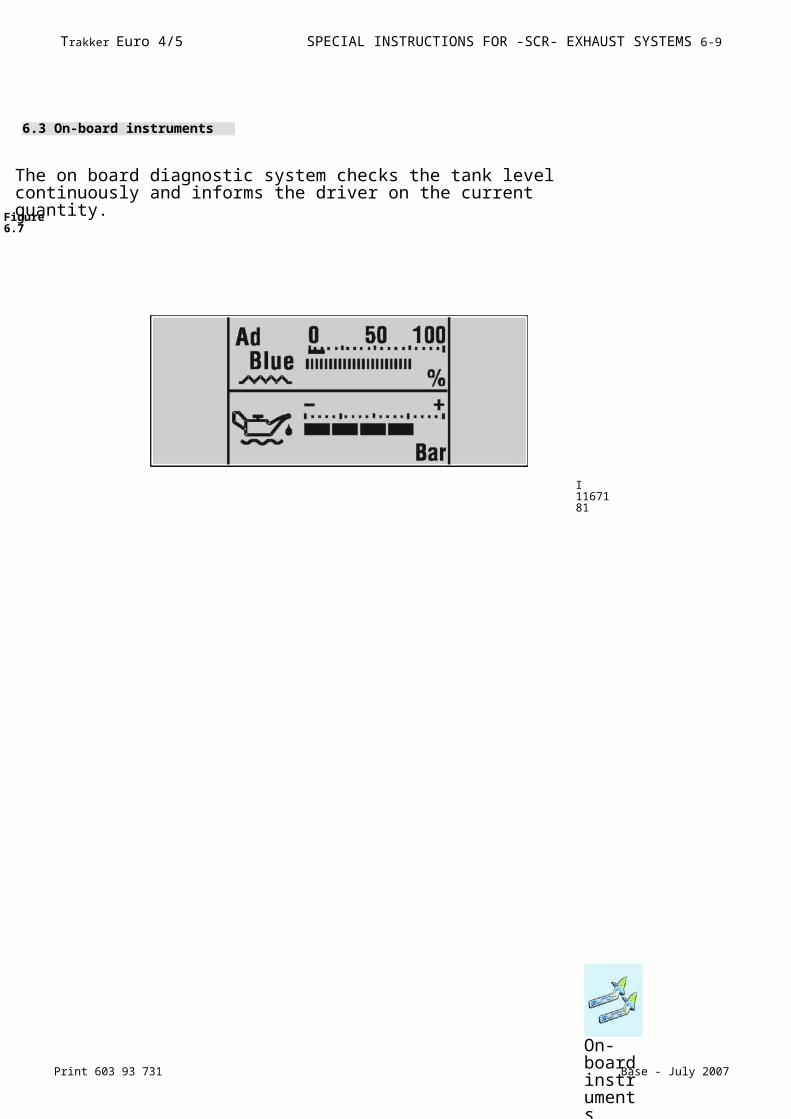
Trakker Euro 4/5 SPECIAL INSTRUCTIONS FOR -SCR- EXHAUST SYSTEMS 6- 1 13
Print 603 93 731 Base - July 2007Specifications for installation and removal
Figure 6.14
The temperature and level sensors are connected to the DCU (Dosing Control Unit); the level sensor is specific to each type of tank, therefore its dimensions cannot be modified.
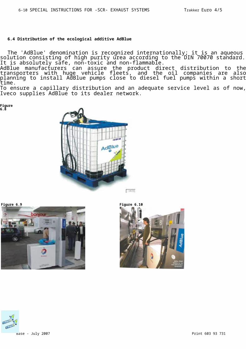
6- 14 SPECIAL INSTRUCTIONS FOR -SCR- EXHAUST SYSTEMS Trakker Euro 4/5
Base - July 2007 Print 603 93 731Specifications for installation and removal
6.5.2 Operations on AdBlue pipes and heating water
As far as the pipes connecting reservoir, supply module and dosing module are concerned, ensure that:- the connection pipes between the AdBlue reservoir and the supply module (delivery or inlet line or return or return line) must be 5 m long at most and the maximum pressure drop must be 100 hPa under all circumstances;- the connection pipes between the supply module and the dosing module (delivery or pressure line and return or cooling line) must be 3 m long at most and the maximum pressure drop must be 100 hPa under all circumstances;The pipes may only be modified using the "Voss" fittings described in Table 6 .13 .
Table 6.13 - AdBlueVOSS/IVECO
T e i l - N r P a r t - N o :
BENENNUNG ITEMNAME DESCRIZIONE DESCRIPTION DESCRIPCIÓN
114489
5 4 6 2 0 7 0 0 0 0 4 1 2 8 3 7 3 3 E Z 5 0 - 7 4 9 9
W i n k e l k u p p l un g S V 2 4 1 5 / 1 6 "A u s f ü h r u n g l i n k s ,m i t M L T 8 8 x 1 4 P A 0 2
E L B O W C O N N E C T O R S V 2 4 I 5 / 1 6 " V E R S I O N L E F T , W I T H M L T 8 8 x 1 4 P A 0 2
R A C C O R D O A N G O L O S V 2 4 I 5 / 1 6 " V E R S I O N E S I N I S T R A , C O N M L T 8 8 x 1 4 P A 0 2
R A C C O R D A N G L E S V 2 4 I 5 / 1 6 " V E R S I O N G A U C H E , A V E C M L T 8 8 x I 4 P A 0 2
C O N E X I O N E N A N G U L O S V 2 4 I 5 / 1 6 " V E R S I O N I Z Q U I E R D A , C O N M L T 8 8 x 1 4 P A 0 2
114490
5 4 6 2 0 7 5 6 0 0 4 1 2 8 3 7 3 4 E Z 5 0 - 7 4 9 9
W i n k e l k u p p l un g S V 2 4 1 5 / 1 6 " A u s f ü h r u n g r e c h t s , m i t M L T 8 8 x 1 4
E L B O W C O N N E C T O R S V 2 4 I 5 / 1 6 " V E R S I O N R I G H T , W I T H M L T 8 8 x 1 4
R A C C O R D O A N G O L O S V 2 4 I 5 / 1 6 " V E R S I O N E D E S T R A , C O N M L T 8 8 x 1 4
R A C C O R D A N G L E S V 2 4 I 5 / 1 6 " V E R S I O N D R O I T E , A V E C M L T 8
C O N E X I O N E N A N G U L O S V 2 4 I 5 / 1 6 " V E R S I O N D E R E C H A , C O N M L T 8
11 T ~ D D114490
5 4 6 2 0 8 8 9 0 0 4 1 2 8 3 7 3 5 E Z 5 0 - 7 4 9 9
G e r a d e k u p p lu n g S V 2 4 1 5 / 1 6 " ,m i t M L T 8 8 x 1 4 P A 0 2L a n g e 3 m
C O N N E C T O R S V 2 4 1 5 / 1 6 " , W I T H M L T 8 8 x 1 4 P A 0 2 L E N G T H 3 m
R A C C O R D O S V 2 4 I 5 / 1 6 " , C O N M L T 8 8 x 1 4 P A 0 2 L U N G H E Z Z A 3 m E
R A C C O R D S V 2 4 I 5 / I 6 " , A V E C M L T 8 8 x I 4 P A 0 2 L O N G U E U R 3 m E T B A G U E
C O N E X I O N S V 2 4 I 5 / 1 6 " , C O N M L T 8 8 x 1 4 P A 0 2 L O N G I T U D 3 m Y
114492
5 4 6 2 2 3 2 6 0 0 4 1 2 8 3 7 3 6 E Z 5 0 - 7 4 9 9
W i n k e l k u p p l un g S V 2 4 1 3 / 8 " A u s f ü h r u n g l i n k s , m i t M L T 8 8 x 1 4 P A 0 2 L a n g e
E L B O W C O N N E C T O R S V 2 4 I 3 / 8 " V E R S I O N L E F T , W I T H M L T 8 8 x 1 4 P A 0 2 L E N G T H
R A C C O R D O A N G O L O S V 2 4 I 3 / 8 " V E R S I O N E S I N I S T R A , C O N M L T 8 8 x 1 4 P A 0 2
R A C C O R D A N G L E S V 2 4 I 3 / 8 " V E R S I O N G A U C H E , A V E C M L T 8 8 x I 4 P A 0 2 L O N G U E U R 3
C O N E X I O N E N A N G U L O S V 2 4 I 3 / 8 " V E R S I O N I Z Q U I E R D A , C O N M L T 8 8 x 1 4 P A 0 2
114493
5 4 6 2 2 3 4 9 0 0 4 1 2 8 3 7 3 7 E Z 5 0 - 7 4 9 9
W i n k e l k u p p l un g S V 2 4 1 3 / 8 " A u s f ü h r u n g r e c h t s , m i t M L T 8 8 x 1 4
E L B O W C O N N E C T O R S V 2 4 I 3 / 8 " V E R S I O N R I G H T , W I T H M L T 8 8 x 1 4
R A C C O R D O A N G O L O S V 2 4 I 3 / 8 " V E R S I O N E D E S T R A , C O N M L T 8 8 x I 4
R A C C O R D A N G L E S V 2 4 I 3 / 8 " V E R S I O N D R O I T E , A V E C M L T 8 8 x I 4 P A 0 2
C O N E X I O N E N A N G U L O S V 2 4 I 3 / 8 " V E R S I O N D E R E C H A , C O N M L T 8
114494
5 4 6 2 2 3 5 0 0 0 4 1 2 8 3 7 3 8 E Z 5 0 - 7 4 9 9
G e r a d e k u p p lu n g S V 2 4 1 3 / 8 " ,m i t M L T 8 8 x 1 4 P A 0 2L a n g e 3 m
C O N N E C T O R S V 2 4 I 3 / 8 " , W I T H M L T 8 8 x I 4 P A 0 2 L E N G T H 3 m A N D
R A C C O R D O S V 2 4 I 3 / 8 " , C O N M L T 8 8 x I 4 P A 0 2 L U N G H E Z Z A 3 m E
R A C C O R D S V 2 4 I 3 / 8 " , A V E C M L T 8 8 x I 4 P A 0 2 L O N G U E U R 3 m E T B A G U E
C O N E X I O N S V 2 4 I 3 / 8 " , C O N M L T 8 8 x I 4 P A 0 2 L O N G I T U D 3 m Y
5 114495
5 4 6 2 2 4 7 0 0 0 4 1 2 8 3 7 3 9 E Z 5 0 - 7 4 9 9
W i n k e l s t e c k er S V 2 4 6 N G 8 O f f n u n g s e l em e n t w e i s s , m i t M L T 8 8 x 1 4 P A 0 2 L a n g e 3 m
E L B O W C O N N E C T O R S V 2 4 6 N G 8 R E L E A S E C L I P W H I T E , W I T H M L T 8 8 x I 4 P A 0 2
R A C C O R D O A N G O L O S V 2 4 6 N G 8 E L E M E N T O D I A P E R T U R A B I A N C O , C O N M L T 8 8 x I 4
R A C C O R D A N G L E S V 2 4 I 8 / 1 6 " E L E M E N T D ' O U V E R T U RE B L A N C , A V E C M L T 8
C O N E X I O N E N A N G U L O S V 2 4 6 N G 8 E L E M E N T O D E A P E R T U R A B L A N C O , C O N M L T 8 8 x I 4
l:114496
5 4 6 2 2 7 6 0 0 0 4 1 2 8 3 7 0 E Z 5 0 -7 4 9 9
W i n k e l s t e c k er S V 2 4 6 N G 8 O f f n u n g s e l em e n t s c h w a r z , m i t M L T 8 8 x 1 4 P A 0 2 L a n g e
E L B O W C O N N E C T O R S V 2 4 6 N G 8 R E L E A S E C L I P B L A C K , W I T H M L T 8 8 x I 4 P A 0 2
R A C C O R D O A N G O L O S V 2 4 6 N G 8 E L E M E N T O D I A P E R T U R A N E R O , C O N M L T 8 8 x I 4
R A C C O R D A N G L E S V 2 4 I 8 / 1 6 " E L E M E N T D ' O U V E R T U RE N O I R , A V E C M L T 8 8 x I 4
C O N E X I O N E N A N G U L O S V 2 4 6 N G 8 E L E M E N T O D E A P E R T U R A N E G R O , C O N M L T 8 8 x I 4
S j l E Í p a ® 4114497
5 4 6 6 1 2 0 6 4 9 4 1 2 8 3 7 4 1 E Z 5 0 - 7 4 9 9
S e t V e r b i n d e r M L T ,1 V e r b i nd e r N W 621 - O h r S c h e l l e n1 M o n t a g e a n l e it u n g
S E T C O N N E C T O R M L T ,1 C O N N EC T O R N W 62 R E T A I NI N G C L I P1 A S S E MB L Y I N S T R U C T I O N
S E T D I R A C C O R D O ,1 R A C C OR D O N W 62 F A S C ET T A1 I S T R U ZI O N E D I M O N T A G G I O P R E S T A R E
S E T D E R A C C O R D ,1 R A C C OR D N V V 62 C O L L I ERI I N S T R U C T I O N D E M O N T A G E R E S P E C T E R
J U E G O D E C O N E X I O N ,1 R A C O RN W 62 A B R A ZA D E R A SI I N S T R U C C I O NE S D E M O N T A J E
CD
•©.
Î E B E S e ii l l114498
5 4 6 4 1 1 1 6 0 0 4 1 2 8 3 7 4 2 E Z 5 0 - 7 4 9 9
R o h rM L T 8 8 x 1 4 P A 0 2 L a n g e 1 0 m
T U B E M L T 8 8 x I 4 P A 0 2 L E N G T H I 0 m
T U B O M L T 8 8 x I 4 P A 0 2 L U N G H E Z Z A I 0 m
T U B E M L T 8 8 x I 4 P A 0 2 L O N G U E U R I 0 m
T U B O M L T 8 8 x I 4 P A 0 2 L O N G I T U D I 0 m
I D G D = D
114500
5 4 6 2 3 5 7 4 0 0 4 1 2 8 3 7 4 3 E Z 5 0 - 7 4 9 9
S t e c k e r T r e n n s t e l l e , m i t M L T 8 8 x 1 4 P A 0 2 L a n g e 3 m u n d
C O N N E C T O R S E C T I O N P O I N T , W I T H M L T 8 8 x I 4 P A 0 2 L E N G T H 3 m
R A C C O R D O P I A S T R A D I S E Z I O N A M E NT O , C O N M L T 8 8 x I 4 P A 0 2 L U N G H E Z Z A
R A C C O R D P L A Q U E D E S E C T I O N N E ME N T , A V E C M L T 8 8 x I 4 P A 0 2
C O N E X I O N C H A P A D E S E P A R A C I O N , C O N M L T 8 8 x I 4 P A 0 2 L O N G I T U D 3
CP=>a
5 4 6 2 3 5 7 5 0 0 4 1 2 8 3 7 4 4 E Z 5 0 - 7 4 9 9
K u p p l u n gT r e n n s t e l l e ,m i t M L T 8 8 x 1 4 P A 0 2 L a n g e 3 m u n d
C O N N E C T O R S E C T I O N P O I N T , W I T H M L T 8 8 x I 4 P A 0 2 L E N G T H 3 m
R A C C O R D O P I A S T R A D I S E Z I O N A M E NT O , C O N M L T 8 8 x I 4 P A 0 2 L U N G H E Z Z A
R A C C O R D P L A Q U E D E S E C T I O N N E ME N T , A V E C M L T 8 8 x I 4 P A 0 2
C O N E X I O N C H A P A D E S E P A R A C I O N , C O N M L T 8 8 x I 4 P A 0 2 L O N G I T U D 3

Trakker Euro 4/5 SPECIAL INSTRUCTIONS FOR -SCR- EXHAUST SYSTEMS 6- 1 15
Print 603 93 731 Base - July 2007Specifications for installation and removal
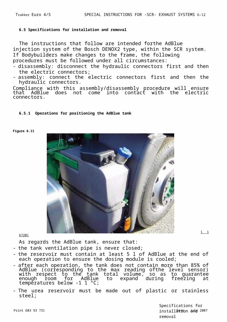
6- 16 SPECIAL INSTRUCTIONS FOR -SCR- EXHAUST SYSTEMS Trakker Euro 4/5
Base - July 2007 Print 603 93 731Specifications for installation and removal
Table 6.1 - (cont.) Cooling water
VOSS/IVECO
Teil -Nr Part -No:Codice:
Benennung Itemname Descrizione Description Descripción
5 4 62 28 42 00 4128 3745 EZ 50-7499
Winkelstecker SV246 NG 1 2 Öffnungselement weiss, mit Rohr Grilamicl 13x1.5 Lange 3m
ELBOW CONNECTOR SV246 NG 12 RELEASE CLIP WHITE, WITH GRILAMIDTUBE 13x1 5 LENGTH 3m
RACCORDO ANGOLO SV246 NG 12 ELEMENTO DI APERTURA BIANCO, CON TUBO GRILAMID 13x1 5 LUNGHEZZA 3m
RACCORD ANGLE SV246 NG 12 ELEMENT D'OUVERTURE BLANC, AVEC TUBE GRILAMID 13x1 5 LONGUEUR 3m
CONEXION EN ANGULO SV246 NG 12 ELEMENTO DE APERTURA BLANCO, CON TUBO GRILAMID 13x1 5 LONGITUD 3 m
5 4 62 29 49 00 4128 3746 EZ 50-7499
4128 3747 EZ 50-7499
5 4 64 19 08 00 4128 3748 EZ 50-7499
Winkelstecker SV246 NG 1 2 Öffnungselement blau, mit Rohr Grilamid 13x1,5 Lange 3m
ELBOW CONNECTOR SV246 NG 12 RELEASE CLIP BLUE, WITH TUBE GRILAMID 13x1 5 LENGTH 3m
RACCORDO ANGOLO SV246 NG 12 ELEMENTO DI APERTURA BLU, CON TUBO GRILAMID 13x1 5 LUNGHEZZA 3m
RACCORD ANGLE SV246 NG 12 ELEMENT D'OUVERTURE BLEU, AVEC TUBE GRILAMID 13x1 5 LONGUEUR 3m
CONEXION EN ANGULO SV246 NG 12 ELEMENTO DE APERTURA AZUL, CON TUBO GRILAMID 13x1 5 LONGITUD 3 mVerbinder
NW 10CONNECTOR NW 10
RACCORDO NW 10
RACCORD NW 10
CONEXION NW 10
Rohr GRILAMID 13x1 5 Lange 10m
TUBE GRILAMID 13x1 5 LENGTH 10m
TUBO GRILAMID 13x1 5 LUNGHEZZA 10m
TUBE GRILAMID 13x1 5 LONGUEUR 10m
TUBO GRILAMID 13x1 5 LONGITUD 10 m
5 4 62 35 76 00 4128 3749 EZ 50-7499
SteckerTrennstelle, mit Rohr Grilamid 13x1,5 Lange 3m
CONNECTOR SECTION POINT, WITH TUBE GRILAMID 13x1 5 LENGTH 3m
RACCORDO PIASTRA DI SEZIONAMENTO, CON TUBO GRILAMID 13x1,5 LUNGHEZZA 3m
RACCORD PLAQUE DE SECTIONNEMENT AVEC TUBE GRILAMID 13x1,5 LONGUEUR 3m
CONEXION CHAPA DE SEPARACION, CON TUBO GRILAMID 13x1,5 LONGITUD 3 m5 4 62 35
77 00 4128 3750 EZ 50-7499
Kupplung Trennstelle, mit RohrGrilamid 13x1,5 Lange 3m1
14507
CONNECTOR SECTION POINT, WITH TUBE GRILAMID 1 3x 1 5 LENGTH 3m
RACCORDO PIASTRA DI SEZIONAMENTO, CON TUBO GRILAMID 13x1,5 LUNGHEZZA 3m
RACCORD PLAQUE DE SECTIONNEMENT AVEC TUBE GRILAMID 13x1,5 LONGUEUR 3m
CONEXION CHAPA DE SEPARACION, CON TUBO GRILAMID 13x1,5 LONGITUD 3 m
Table 6.1 - (cont.) Corrugated pipe
VOSS/IVECO
Teil -Nr Part -No:Codice:
Benennung Itemname Descrizione Description Descripción
5 4 66 11 37 00 4128 3751 EZ 50-7499
Wellrohr NW37 Lange 3m
CORRUGATED HOSE NW37 LENGTH 3m
TUBO CORRUGATO NW37 LUNGHEZZA 3m
TUBE CANNELE NW37 LONGUEUR 3m
TUBO CORRUGADO NW37 LONGITUD 3 m5 4 66 12
10 00 4128 3752 EZ 50-7499
Wellrohr NW26 Lange 3m
CORRUGATED HOSE NW26 LENGTH 3m
TUBO CORRUGATO NW26 LUNGHEZZA 3m
TUBE CANNELE NW26 LONGUEUR 3m
TUBO CORRUGADO NW26 LONGITUD 3 m
"imioil
5 4 66 12 09 00 4128 3753 EZ 50-7499
Wellrohr NW22 Lange 3m
CORRUGATED HOSE NW22 LENGTH 3m
TUBO CORRUGATO NW22 LUNGHEZZA 3m
TUBE CANNELE NW22 LONGUEUR 3m
TUBO CORRUGADO NW22 LONGITUD 3 m
Table 6.1 - (cont.) Breather pipeVOSS/IVECO
T e i l - N r P a r t - N o :
BENENNUNG ITEMNAME DESCRIZIONE DESCRIPTION DESCRIPCIÓN
C D
5 4 6 6 0 9 6 5 0 0 4 1 2 8 3 7 5 7 E Z
V e r b i n d e r N W 6
C O N N E C T O R N W 6
R A C C O R D O N W 6
R A C C O R D N W 6
C O N E X I O N N W 6
5 4 6 4 1 9 0 9 0 0 4 1 2 8 3 7 5 8 E Z
R o h r 6 x 1 P A I 2 P H L Y L a n g e 1 0 m
T U B E 6 x 1 P A I 2 P H L Y L E N G T H 1 0 m
T U B O 6 x 1 P A I 2 P H L Y L U N G H E Z Z A I 0 m
T U B E 6 x 1 P A I 2 P H L Y L O N G U E U R 1 0 m
T U B O 6 x 1 P A 1 2 P H L Y L O N G I T U D 1 0 m
-t----? — t-
0 • 0 .1 145
12
031 14513
5 4 6 6 1 0 2 1 0 0 4 1 2 8 3 7 5 9 E Z 5 0 - 7 4 9 9
V e r b i n d e r N W 1 0
C O N N E C T O R N W 1 0
R A C C O R D O N W I 0
R A C C O R D N W I 0
C O N E X I O N N W 1 0
1 0
10
. .
•0. 114478
5 4 6 4 1 9 1 0 0 0 4 1 2 8 3 7 6 0 E Z 5 0 - 7 4 9 9
R o h r 1 0 x 1 P A I 2 P H L Y L a n g e 1 0 m
T U B E 1 0 x 1 P A I 2 P H L Y L E N G T H 1 0 m
T U B O 1 0 x 1 P A I 2 P H L Y L U N G H E Z Z A I 0 m
T U B E 1 0 x 1 P A I 2 P H L Y L O N G U E U R 1 0 m
T U B O 1 0 x 1 P A 1 2 P H L Y L O N G I T U D 1 0 m
1 14506
Trakker Euro 4/5 SPECIAL INSTRUCTIONS FOR -SCR- EXHAUST SYSTEMS 6- 1 17
Print 603 93 731 Base - July 2007Specifications for installation and removal
Table 6.1 - (cont.) Components
- When working on the pipes, it is compulsory to work in a completely dust-free environment to prevent dust reaching the injector.- Restore all the pipe insulation (water and Urea pipes) to prevent freezing.
VOSS/IVECO
T e i l - N r P a r t - N o :
BENENNUNG ITEMNAME DESCRIZIONE DESCRIPTION DESCRIPCIÓN
114477
5 0 9 9 1 1 6 4 0 0 4 1 2 8 3 7 6 1 E Z 5 0 - 7 4 9 9
S c h u t z k a p p e T a n k 0 °
P R O T E C T I O N C A P T A N K 0 °
C A P P A D I P R O T E Z I O N E S E R B A T O I O 0 °
C A P U C H O N D E P R O T E C T I O N R E S E R V O I R 0 °
C O B E R T U R A D E P R O T E C C I O N D E P O S I T O 0 °
114488
5 0 9 9 1 1 7 1 0 0 4 1 2 8 3 7 6 2 E Z 5 0 - 7 4 9 9
S c h u t z k a p p e T a n k 9 0 °
P R O T E C T I O N C A P T A N K 9 0 °
C A P P A D I P R O T E Z I O N E S E R B A T O I O 9 0 °
C A P U C H O N D E P R O T E C T I O N R E S E R V O I R 9 0 °
C O B E R T U R A D E P R O T E C C I O N D E P O S I T O 9 0 °
fSIP5 4 6 6 0 9 3 0 0 0 4 1 2 8 3 7 6 3 E Z 5 0 - 7 4 9 9
F a l t e n b a l gC O N V O L U T E D R U B B E R G A I T E R
S O F F I E T T O S O U F F L E T R E S P I R A D E R O
<S»114508
5 4 6 6 0 9 6 4 0 0 4 1 2 8 3 7 6 4 E Z 5 0 - 7 4 9 9
T - S t ü c k f ü r W e l l r o h r N W 3 7
T -C O N N E C T O R FO R C O R R U G A T E D H O S E N W 3 7
D I S T R I B U T O RE A T P E R T U B O C O R R U G A T O N W 3 7
D I S T R I B U T E UR E N T P O U R T U B E A N N E L E N W 3 7
D I S T R I B U I D OR E N T P A R A T U B O C O R R U G A D O N W 3 7
114509
5 3 4 9 0 3 2 1 0 0 4 1 2 8 3 7 6 5 E Z 5 0 - 7 4 9 9
D e c k p l a t t e T r e n n s t e l l e
C O V E R P L A T E S E C T I O N P O I N T
P I A S T R A D I C O P E R T U R A P U N T O D I S E Z I O N A M E NT O
P L A Q U E D EC O U V E R T U R E P O I N T D E S E C T I O N N E ME N T
C H A P A D E C O B E R T U R A P U N T O D E S E P A R A C I O N
1 14510
5 3 4 9 0 3 2 0 4 9 4 1 2 8 3 7 6 6 E Z 5 0 - 7 4 9 9
G r u n d p l a t t e T r e n n s t e l l e
B A S E P L A T E S E C T I O N P O I N T
P I A S T R A D I B A S E P U N T O D I S E Z I O N A M E NT O
P L A Q U E D E B A S E P O I N T D E S E C T I O N N E ME N T
C H A P A D E B A S E P U N T O D E S E P A R A C I O N
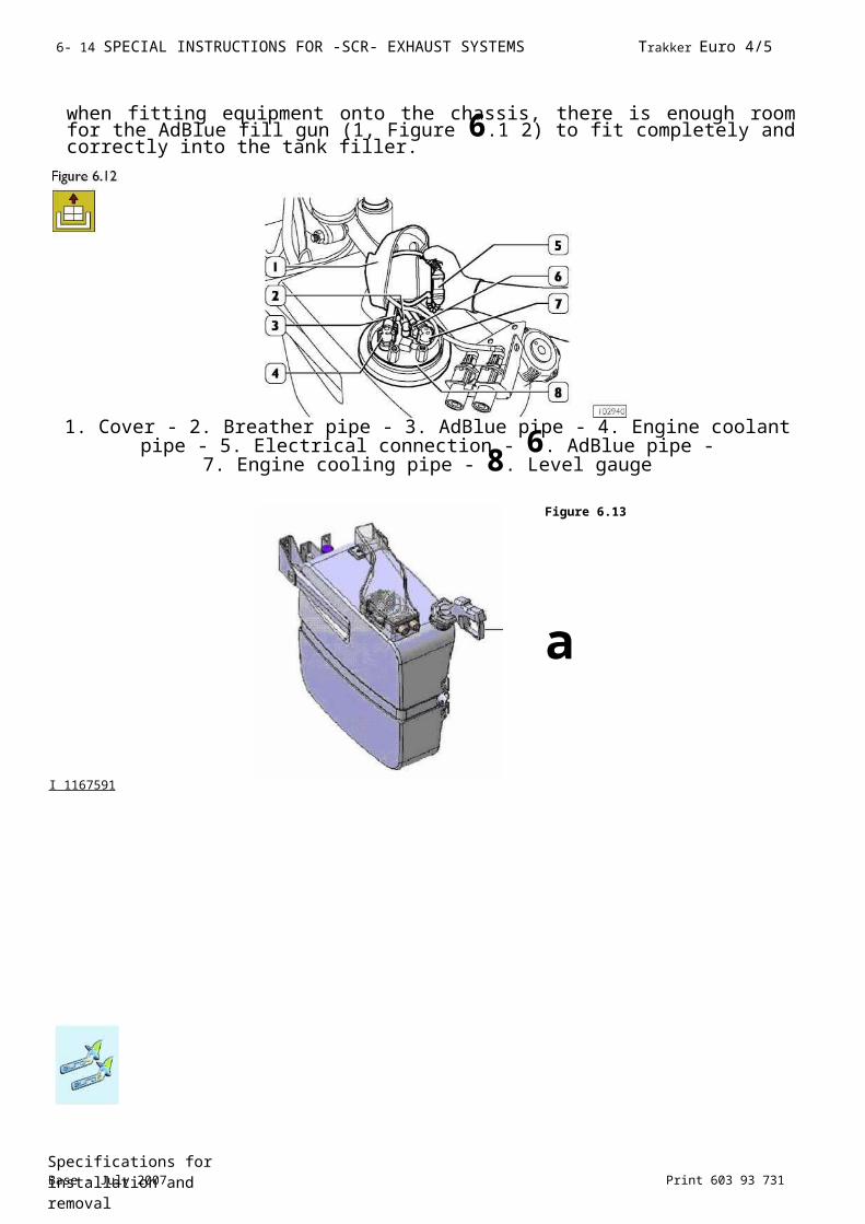
6- 18 SPECIAL INSTRUCTIONS FOR -SCR- EXHAUST SYSTEMS Trakker Euro 4/5
Base - July 2007 Print 603 93 731Specifications for installation and removal
6.5.3 Altering the supply module position
If the supply module requires repositioning, scrupulously observe the instructions in Figure 6.15. The module must be installed horizontally and on a rigid mount.
Figure 6.15
1. AdBlue reservoir - 2. Pumping module - 3. Dosing module - 4. Siphon compulsory
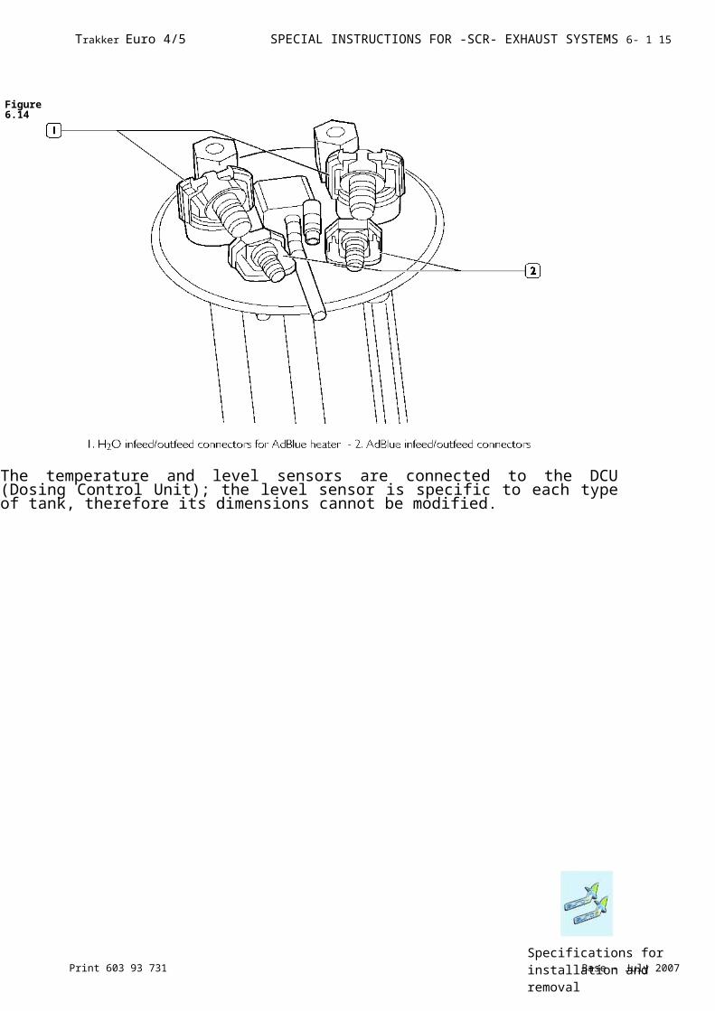
Base - July 2007 Print 603 93 731Specifications for installation and removal
6- 1 6 SPECIAL INSTRUCTIONS FOR -SCR- EXHAUST SYSTEMS Trakker Euro 4/5
6.5.4 Operations on the dosing module
When the dosing module requires repositioning, note
some important precautions. FIGURE 6.16
STRUCTURE OF THE MEASURING MODULE1. Heatshield - 2. Temperature sensor - 3. Valve holder - 4. AdBlue connectors - 5.
Dosing valve - 6. Cooling adapter -7. Insulation
- As regards the AdBlue piping connecting the tank (1), the supply module and the dosing module, ensure that:
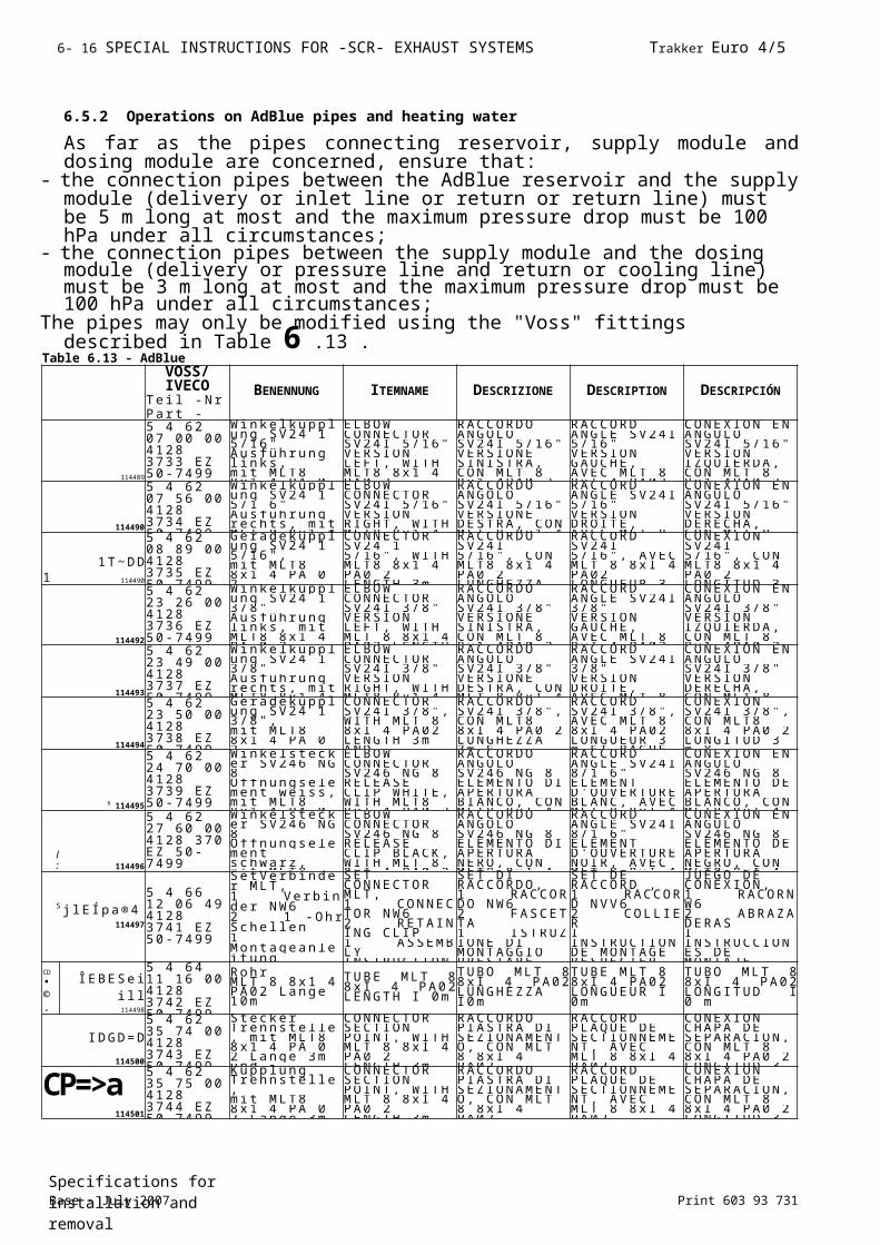
Base - July 2007 Print 603 93 731Specifications for installation and removal
6- 1 6 SPECIAL INSTRUCTIONS FOR -SCR- EXHAUST SYSTEMS Trakker Euro 4/5
Specifications for installation and removal
Print 603 93 731 Base - July 2007
Trakker Euro 4/5 SPECIAL INSTRUCTIONS FOR -SCR- EXHAUST SYSTEMS 6- 17
1. Exhaust gas pipe tract involved by the injection of the AdBlue solution - 2. Dosing Module position: -45° / 180° - Exhaust
pipe low in at catalyst
The supply module:- must not be fitted too near to the turbine to prevent it overheating;- must not be fitted too near the catalytic converter input to prevent the build-up of carbon deposits.
NOTE If the dosing module is moved, the pipes and electrical wiring must be modified.
6.5.5 Operations on exhaust pipes
NOTE The exhaust pipe layout cannot be changed without the approval of IVECO.
The exhaust pipe can be modified paying attention to the following warnings:- type approved (homologated) counter-pressures must be respected when determining the exhaust pipe route. Form bends with angles greater than 90° and radius of curvature greater than 2.5 times the pipe diameter. Keep the exhaust pipe far enough away from rubber or plastic parts and fit heat shields if necessary.- It is not permitted to use pipes with diameters, thicknesses and materials other than those used for the original equipment.
- It is permitted to use hoses with limited lengths. Electrical wiring
- It is only possible to lengthen cables for the temperature sensors.- It is not possible to alter the length of the Nox sensor cable.
Figure 6.18
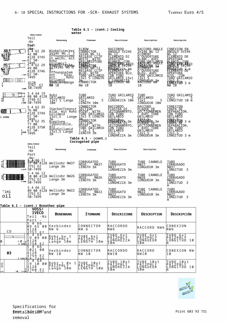
Specifications for installation and removalBase - July 2007 Print 603 93 731
6- 18 SPECIAL INSTRUCTIONS FOR -SCR- EXHAUST SYSTEMS Trakker Euro 4/5