Embed Size (px)
Citation preview

SECTION 3 UNDERGROUND SERVICES
Standard Specification for Urban Infrastructure Works 3-1 Edition 1, Revision 0 / September 2002
CONTENTS
3 UNDERGROUND SERVICES 3-2
3.01 SCOPE 3-2
3.02 STANDARDS 3-2
3.03 EXCAVATION AND BACKFILLING 3-4 3.03.1 Clearing and Grubbing 3-4 3.03.2 Excavation 3-4 3.03.3 Use of Explosives 3-7 3.03.4 Shoring 3-7 3.03.5 Restoration of Grassed and Prepared Areas 3-8 3.03.6 Trench Dimensions 3-9 3.03.7 Protection and Drainage of Hydraulic Works 3-10 3.03.8 Backfilling 3-11 3.03.9 Disposal of Surplus Spoil 3-12 3.03.10 Conformance Criteria 3-12 3.03.11 Nonconforming Work 3-14
3.04 SEWERAGE 3-15 3.04.1 General 3-15
3.05 STORMWATER DRAINAGE 3-15 3.05.1 Materials 3-15 3.05.2 Pipe Bedding and Side Support 3-18 3.05.3 Laying and Jointing of Pipes and Culverts 3-18 3.05.4 Drainage Structures 3-20 3.05.5 Conformance Criteria 3-22 3.05.6 Acceptance by Stormwater Authority 3-25
3.06 SUBSOIL DRAINS 3-25 3.06.1 Materials 3-25 3.06.2 Trenches 3-27 3.06.3 Bedding, Laying and Jointing 3-28 3.06.4 Finishing 3-28 3.06.5 Conformance Criteria 3-29
3.07 CONDUITS 3-31 3.07.1 General 3-31 3.07.2 Materials 3-31 3.07.3 Trenching 3-32 3.07.4 Installation 3-32 3.07.5 Conformance Criteria 3-33
3.08 WATER SUPPLY MAINS 3-34
3.09 WATER SERVICES 3-35
3.10 EXCAVATION BY BORING 3-35
3.11 MEASUREMENT AND PAYMENT 3-37
3.12 SCHEDULE OF HOLD POINTS 3-53

SECTION 3 UNDERGROUND SERVICES
Standard Specification for Urban Infrastructure Works 3-2 Edition 1, Revision 0 / September 2002
3 UNDERGROUND SERVICES
3.01 SCOPE
The works covered by this Section of the Specification comprise the construction of all piped underground services for water supply, sewerage, stormwater drainage, service conduits and subsoil drains. The construction of open earth drains is not included, these works being covered by Section 2 "Earthworks".
3.02 STANDARDS
Work carried out and testing performed under this Section of the Specification shall comply with the requirements of the following Standards to the extent that they are relevant and not overridden by the Specification.
Australian Standards
AS 1074 Steel Tubes and Tubulars for Ordinary Service
AS 1111 ISO Metric Hexagon Commercial Bolts and Screws
AS 1112 ISO Metric Hexagon Nuts, including thin nuts, slotted nuts and castle nuts
AS 1214 Hot Dip Galvanised Coatings on Threaded Fasteners (ISO Metric Coarse Thread Series)
AS 1254 Unplasticised PVC (uPVC) Pipes and Fittings for Storm or Surface Water Applications
AS 1260 PVC Pipes and Fittings for Drain, Waste and Vent Applications
AS 1289 Methods of Testing Soils for Engineering Purposes
AS 1302 Steel Reinforcing Bars for Concrete
AS 1303 Hard Drawn Steel Reinforcing Wire for Concrete
AS 1304 Welded Wire Reinforcing Fabric for Concrete
AS 1432 Copper Tubes for Water, Gas and Sanitation
AS 1477 PVC Pipes and Fittings for Pressure Applications
AS 1554 Structural Steel Welding Code
AS 1579 Arc welded Steel Pipes and Fittings for Water and Waste Water
AS 1597 Precast Reinforced Concrete Box Culverts
AS 1646 Rubber Joint Rings for Water Supply, Sewerage and Drainage Purposes
AS 1718 Water Supply - Copper Alloy Screw-down Pattern Taps - Specified by Dimensions
AS 1741 Vitrified Clay Pipes and Fittings with Flexible Joints – Sewer Quality
AS 2032 Code of Practice for Installation of uPVC Pipe Systems
AS 2053 Non-Metallic Conduits and Fittings

SECTION 3 UNDERGROUND SERVICES
Standard Specification for Urban Infrastructure Works 3-3 Edition 1, Revision 0 / September 2002
AS 2129 Flanges for Pipes, Valves and Fittings
AS 2280 Ductile Iron Pressure Pipes and Fittings
AS 2439 Perforated Plastics Drainage and Effluent Pipe and Fittings
AS 2544 Grey Iron Pressure Pipes and Fittings
AS 2566.1 Buried Flexible Pipelines – Structural Design
AS 2638 Cast Iron Sluice Valves for Waterworks Purposes
AS 2648.1 Underground Marking Tape – Non detectable tape
AS 2701.4 Methods of Sampling and Testing Mortar for Masonry Constructions – Method for Determination of Compressive Strength
AS 2865 Safe Working in Confined Space
AS 2977 Unplasticised PVC (uPVC) Pipes for Pressure Applications – Compatible with Cast Iron Pipe Outside Diameters
AS 3500 National Plumbing and Drainage Code – Compendium
AS 3500.0 Glossary of Terms
AS 3500.1 Water Supply
AS 3500.2 Sanitary Plumbing and Drainage
AS 3500.3 Stormwater Drainage
AS 3578 Cast Iron Non Return Valve for General Purposes
AS 3600 Concrete Structures
AS 3680 Polyethylene Sleeving for Ductile Iron Pipelines
AS 3681 Guidelines for the Application of Polyethylene Sleeving to Ductile Iron Pipelines and Fittings
AS 3705 Geotextiles – Identification, Marking and General Data
AS 3706 Geotextiles – Methods of Test
AS 3725 Loads on Buried Concrete Pipes
AS 3972 Portland and Blended Cements
AS 3996 Metal Access Covers, Road Grates and Frames
AS 4058 Precast Concrete Pipes (pressure and non-pressure)
AS 4060 Loads on Buried Vitrified Clay Pipes
AS 4087 Metallic Flanges for Wastewater Purposes
AS 4139 Fibre reinforced Concrete Pipes and Fittings
AS 4680 Hot-dipped galvanised (zinc) Coatings on Fabricated Ferrous Articles

SECTION 3 UNDERGROUND SERVICES
Standard Specification for Urban Infrastructure Works 3-4 Edition 1, Revision 0 / September 2002
AS 4791 Hot-dipped galvanised (zinc) Coatings on Ferrous Open Sections, Applied by an Inline Process
AS 4792 Hot-dipped galvanised (zinc) Coatings on Ferrous Hollow Sections, Applied by a Continuous Specialised Process
Other Standards and References
ACTEW Water Supply and Sewerage Standards
ACT Urban Services - Urban Stormwater Standard Engineering Practices
AUSTROADS Bridge Design Code
Legislation
Environment Protection Act, 1997
Road Transport (Safety and Traffic Management) Act, 1999
Road Transport (General) Act, 1999
Occupational Health and Safety Act, 1989
Scaffolding and Lift Act, 1957
Dangerous Goods Act, 1975
Dangerous Gods Regulation, 1978
Scaffolding and Lifts Regulations, 1950: Regs: 95,95(Cofferdams and Caissons); 97(Trenches); 98(Shafts, Wells and Tunnels).
Testing
A Testing Authority shall be employed by the Contractor to carry out all testing. The Authority shall hold a current NATA (National Association of Testing Authorities) Registration for the relevant tests, and a copy of results forwarded to the Superintendent without delay.
3.03 EXCAVATION AND BACKFILLING
3.03.1 Clearing and Grubbing Clear, grub and dispose of debris along the alignment of underground services as specified in Clause 2.04.
3.03.2 Excavation
(i) General
The Contractor must comply with Scaffolding and Lifts Regulations 1950: Regs: 95, 96(Cofferdams and Caissons); 97(Trenches); 98(Shafts, Wells and Tunnels). To assure that appropriate safeguards and measures are undertaken for securing the safety and health of persons engaged in excavation work.
The Contractor shall set out the trench alignment clearly marking the specified end points of the trench with pegs. The Superintendent will inspect the set out of the trench prior to the commencement of excavation.
SECTION 3 UNDERGROUND SERVICES
Standard Specification for Urban Infrastructure Works 3-5 Edition 1, Revision 0 / September 2002
The Contractor shall meet with each service authority representative on site to locate all existing services and obtain clearances for potholing and construction. If an existing service is damaged due to the construction the Contractor shall notify the appropriate service authority and the Superintendent immediately. Any damage to existing services shall be repaired at no expense to the Principal.
Before commencing excavation the Contractor shall expose all crossings and connection points on existing services. The levels of each crossing and connection point shall be surveyed and any variations to the levels given or any difficulties in being able to achieve the required grades of new pipelines shall be reported to the Superintendent.
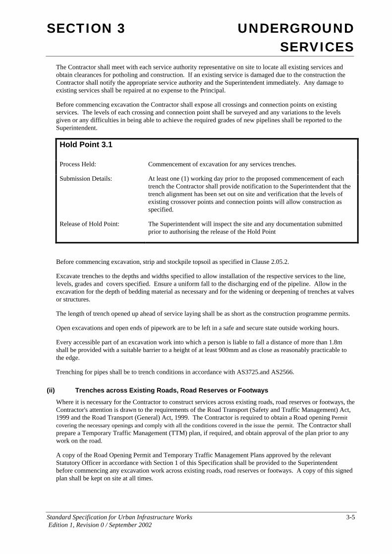
Hold Point 3.1
Process Held: Commencement of excavation for any services trenches.
Submission Details: At least one (1) working day prior to the proposed commencement of each trench the Contractor shall provide notification to the Superintendent that the trench alignment has been set out on site and verification that the levels of existing crossover points and connection points will allow construction as specified.
Release of Hold Point: The Superintendent will inspect the site and any documentation submitted prior to authorising the release of the Hold Point
Before commencing excavation, strip and stockpile topsoil as specified in Clause 2.05.2.
Excavate trenches to the depths and widths specified to allow installation of the respective services to the line, levels, grades and covers specified. Ensure a uniform fall to the discharging end of the pipeline. Allow in the excavation for the depth of bedding material as necessary and for the widening or deepening of trenches at valves or structures.
The length of trench opened up ahead of service laying shall be as short as the construction programme permits.
Open excavations and open ends of pipework are to be left in a safe and secure state outside working hours.
Every accessible part of an excavation work into which a person is liable to fall a distance of more than 1.8m shall be provided with a suitable barrier to a height of at least 900mm and as close as reasonably practicable to the edge.
Trenching for pipes shall be to trench conditions in accordance with AS3725.and AS2566.
(ii) Trenches across Existing Roads, Road Reserves or Footways
Where it is necessary for the Contractor to construct services across existing roads, road reserves or footways, the Contractor's attention is drawn to the requirements of the Road Transport (Safety and Traffic Management) Act, 1999 and the Road Transport (General) Act, 1999. The Contractor is required to obtain a Road opening Permit covering the necessary openings and comply with all the conditions covered in the issue the permit. The Contractor shall prepare a Temporary Traffic Management (TTM) plan, if required, and obtain approval of the plan prior to any work on the road.
A copy of the Road Opening Permit and Temporary Traffic Management Plans approved by the relevant Statutory Officer in accordance with Section 1 of this Specification shall be provided to the Superintendent before commencing any excavation work across existing roads, road reserves or footways. A copy of this signed plan shall be kept on site at all times.

SECTION 3 UNDERGROUND SERVICES
Standard Specification for Urban Infrastructure Works 3-6 Edition 1, Revision 0 / September 2002
Hold Point 3.2
Process Held: Commencement of excavation of trenches in roads, road reserves or footways.
Submission Details: At least three (3) working days prior to proposed excavation of any services trench in roads, road reserves or footways the Contractor shall provide a copy of the Road Opening Permit and the Approved Temporary Traffic Management Plan(s).
Release of Hold Point: The Superintendent will consider the submitted documents prior to authorising the release of the Hold Point
Backfilling of trenches covered by Road Opening Permits shall be as specified in Clause 3.03.8 of this Specification.
As a temporary measure prior to hotmix asphalting the Contractor shall backfill with a temporary layer of asphaltic concrete (Cold Mix) over the road or pathway opening surface. The Cold Mix shall be installed so as to form a raised hump to allow for compaction by traffic. The Contractor shall monitor the performance of the Cold Mix installed and if the surface level of the Cold Mix compacts so as to create a step of more than 30mm to the top of the existing pavement level the Contractor shall add more Cold Mix as appropriate.
(iii) Trenches adjacent Trees and other Existing Services
Unless otherwise specified do not excavate by machine within one (1) metre of existing services or within three (3) metres of existing trees marked to remain.
Trees are to be protected as specified in Clause 2.04.2 prior to commencement of works.
Support and protect all trees, shrubs, pipes and structures in or adjacent to trenches to the satisfaction of the relevant Authorities.
(iv) Trench Foundation
The foundation at the bottom of the trench shall be assessed for conformity to select fill as defined in AS 3725. If the foundation is rock, the trench shall be excavated a further 75mm for concrete and vitrified clay pipes.
Remove or cut back exposed boulders in trench bottoms. Where areas of soft material occur in trench bottoms the Superintendent may require the use of alternative bedding materials as specified in Clauses 3.04.2 and 3.08.2
For pipes with sockets protruding beyond the barrel outside surface, chases shall be cut into the bed of the foundation as necessary, in the appropriate positions, so that each pipe is supported along the full length of the barrel and the socket is not subjected to point loading.
Should the excavation reveal material which is unstable, the trench shall be over-excavated to a depth required to remove the unsuitable material and refill with bedding material compacted to the specified relative compaction as directed by the Superintendent.

SECTION 3 UNDERGROUND SERVICES
Standard Specification for Urban Infrastructure Works 3-7 Edition 1, Revision 0 / September 2002
Hold Point 3.3
Process Held: Placement of bedding material in trench
Submission Details: At least one (1) working day prior to proposed placement of bedding in a trench the Contractor shall provide notification that the foundation of the trench will be ready for inspection.
Release of Hold Point: The Superintendent may inspect the foundation prior to authorising the release of the Hold Point
3.03.3 Use of Explosives A person shall not, receive explosives unless the person is authorised by or under the Dangerous Goods Act 1975. Any person intending to use explosives in the ACT must first be the holder of a Shotfirer’s Permit, issued under the Dangerous Goods Regulations 1978. That person must then obtain a Permit to Use Explosives under the Occupational Health & Safety Regulations. Application for a Permit to Use Explosives should be made to the Registrar under the Occupational Health & Safety Act. Application must be made at least 14 working days prior to the commencement of work involving the use of explosives. The application must be accompanied by a Blast Plan containing all of the information requested in the application form. Application forms are available from ACT WorkCover. To contact ACT WorkCover please dial (02) 6205 0200 or send your inquiry via e-mail to [email protected].
The Contractor shall not, without the prior approval of the Superintendent, use explosives or permit blasting to occur. If approved by the Superintendent, the use of explosives in trench excavation shall comply with the requirements of Clause 2.05.3.
Where parallel services to be constructed under this Contract are less than ten (10) m apart and excavation by blasting is necessary, complete blasting of both trenches before commencing pipe laying.
3.03.4 Shoring The Contractor's attention is drawn to regulations in respect of the Scaffolding and Lift Act, 1957. These regulations are administered by the Chief Inspector, ACT Workcover. The Act requires all trenches greater than 2.5m long and 1.6m deep to be shored. Shoring may be either timber shoring or moveable metal shield shoring. Where shoring is required, ladders shall be provided. Alternatively, trenches may be stepped to avoid the use of shoring provided the depth of the deepest trench is not deeper than 1.5m without shoring.
Shoring shall be progressively placed as close as practical to the excavation equipment as excavation occurs Shoring shall be no more than 3.3m behind the face of excavation.
Excavated material shall be placed no closer than 0.3m from the edge of the trench. In sandy conditions, excavated material shall be placed no closer than 1.0m from the edge of the trench.
The Contractor shall submit details of the proposed method to be used for the construction of all pipes deeper than 1.5m.
SECTION 3 UNDERGROUND SERVICES
Standard Specification for Urban Infrastructure Works 3-8 Edition 1, Revision 0 / September 2002
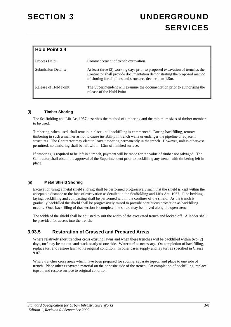
Hold Point 3.4
Process Held: Commencement of trench excavation.
Submission Details: At least three (3) working days prior to proposed excavation of trenches the Contractor shall provide documentation demonstrating the proposed method of shoring for all pipes and structures deeper than 1.5m.
Release of Hold Point: The Superintendent will examine the documentation prior to authorising the release of the Hold Point
(i) Timber Shoring
The Scaffolding and Lift Ac, 1957 describes the method of timbering and the minimum sizes of timber members to be used.
Timbering, when used, shall remain in place until backfilling is commenced. During backfilling, remove timbering in such a manner as not to cause instability in trench walls or endanger the pipeline or adjacent structures. The Contractor may elect to leave timbering permanently in the trench. However, unless otherwise permitted, no timbering shall be left within 1.2m of finished surface.
If timbering is required to be left in a trench, payment will be made for the value of timber not salvaged. The Contractor shall obtain the approval of the Superintendent prior to backfilling any trench with timbering left in place.
(ii) Metal Shield Shoring
Excavation using a metal shield shoring shall be performed progressively such that the shield is kept within the acceptable distance to the face of excavation as detailed in the Scaffolding and Lifts Act, 1957. Pipe bedding, laying, backfilling and compacting shall be performed within the confines of the shield. As the trench is gradually backfilled the shield shall be progressively raised to provide continuous protection as backfilling occurs. Once backfilling of that section is complete, the shield may be moved along the open trench.
The width of the shield shall be adjusted to suit the width of the excavated trench and locked off. A ladder shall be provided for access into the trench.
3.03.5 Restoration of Grassed and Prepared Areas Where relatively short trenches cross existing lawns and when these trenches will be backfilled within two (2) days, turf may be cut out and stack neatly to one side. Water turf as necessary. On completion of backfilling, replace turf and restore lawn to its original condition. In other cases supply and lay turf as specified in Clause 9.07.
Where trenches cross areas which have been prepared for sowing, separate topsoil and place to one side of trench. Place other excavated material on the opposite side of the trench. On completion of backfilling, replace topsoil and restore surface to original condition.

SECTION 3 UNDERGROUND SERVICES
Standard Specification for Urban Infrastructure Works 3-9 Edition 1, Revision 0 / September 2002
3.03.6 Trench Dimensions
(i) Width
Trench excavation generally shall comply with the principles prescribed in the following Codes of Practice for the various types of pipe:
ConcretePipes AS 3725
• Vitrified Clay Pipes AS 4060
• UPVC Pipes AS 2032
• Buried Flexible Pipelines AS 2566
Generally the cut or embankment formation shall be completed to subgrade level before the trench is excavated to the required depth including provision for bedding. Pipes shall be installed to “trench” conditions in accordance with the above Codes of Practice.
Trench widths for sewers, conduits, vitrified clay pipes and water mains shall generally be the external pipe diameter plus 300mm measured at the level of the crown of the pipe. The standard minimum trench width is 600mm.
Concrete pipes shall be installed under” trench” conditions in accordance with AS 3725 unless otherwise specified. Trench widths for concrete pipes shall be 1.4 times the external pipe diameter or the external pipe diameter plus 600mm measured at the level of the crown of the pipe, whichever is greater.
If a trench is excavated to excess width beyond the dimensions given above, or caves in due to inadequate support, or the surrounding natural ground is of poor quality material the pipe may be required to be installed under embankment conditions in accordance with AS 2256 and AS 3725, or a pipe of higher strength class, or both, without additional payment. The Contractor shall advise the Superintendent of any such instances prior to placing bedding material and laying of the pipe.
The standard width of trench for water service and irrigation pipes up to 100mm diameter is 300mm. Subject to compliance with other specified requirements, equipment providing a narrower or wider trench will be permitted.
The standard width of trench for subsoil drains shall be 200mm.
In trenches where shoring is necessary, increase width sufficiently to maintain clearances specified above between face of shoring and pipes.
The width of trenches for curved pipelines shall be adequate to allow correct jointing of rubber ring jointed pipes while providing the minimum clearances from the pipe to the trench walls as given above.
(ii) Allowance for Bedding
Trenches shall be excavated to the pipe design levels shown on the drawings plus the required bedding depth. Allowance shall be made in the depth of the trench for the bedding type specified. For depth of bedding for water and sewer mains, refer to ACT Water Supply and Sewerage Standards Drawings WSS 012 and WSS 056 respectively.
For concrete pipes the depth of bedding shall be a minimum of 100mm for pipes up to and including 1500mm diameter and 150mm depth for all mains larger than 1500mm diameter.
Bedding depth for water services and irrigation pipes shall be 75mm minimum where trench has a rock base. No bedding allowance is required in trenches with earth bases.
Bedding for conduits and subsoil drains shall be 50mm minimum.

SECTION 3 UNDERGROUND SERVICES
Standard Specification for Urban Infrastructure Works 3-10 Edition 1, Revision 0 / September 2002
(iii) Pipe Cover
Where pipe invert levels are not detailed, excavate trenches to provide the minimum pipe covers itemised in Table 3.1. Where pipes are socketed, cover is measured over sockets.
At valve locations on water mains, excavate to a depth which ensures a minimum free space of 75mm between top of spindle and underside of valve box cover.
Table 3.1
Minimum Cover (mm)
Item General Under Roads
Water Mains 600 750
Water Services 450 600
PVC Irrigation Pipes and Control Tubes or Cables
450 600
Telecommunications 450 600
Gas 650 750
Electricity Supply Conduits (Except 50mm diameter conduits inside lease boundaries which shall have 600mm minimum cover))
850 Low Voltage
1100 to invert for High Voltage
950 Low Voltage
1050 High Voltage
Other Conduits (unless specified by Service Authority)
750
Stormwater 600 600
Sewers 600 (general) 750 (road verges)
900 (minor sealed roads) 1200 (unsealed or major
roads)
Notes on Table 3.1
(i) The minimum cover over pipes under roads is measured from the pavement surface with the exception of stormwater mains which is measured from the underside of the sub-base.
3.03.7 Protection and Drainage of Hydraulic Works Provide for the diversion and control of stormwater during construction of underground services as specified in Clause 2.03. Where trenches cannot be drained by gravity, provide pumping equipment to keep excavations dewatered. Water from excavations shall not be drained to any sewer.
If a spring or water seepage is encountered in the walls or foundation of excavations it shall be sealed off or controlled so as to minimise damage to the foundation and subsequent installations.

SECTION 3 UNDERGROUND SERVICES
Standard Specification for Urban Infrastructure Works 3-11 Edition 1, Revision 0 / September 2002
If any material in the excavation has been damaged by water, or backfill has been excessively moistened by uncontrolled inflowing water or springs, the said material or backfill shall be removed from the work and replaced with specified material.
Water in trenches shall be lowered to the bottom of the trench during bedding, pipe laying and backfilling operations to allow the foundation, bedding and backfilling material to be compacted to the specified relative compaction.
Where necessary provide secure and proper temporary fluming for conducting sewage, storm and subsoil water across and beyond the works. The means of discharge shall be located and controlled so as not to cause erosion or damage to the environment. The Contractor shall submit details of the proposed dewatering and discharge method to the Superintendent for approval prior to commencement of trenching.All costs associated with removal of water from excavations shall be borne by the Contractor.
3.03.8 Backfilling Backfilling under this section is the remainder of filling in the trench above the bedding and pipe support material. Backfilling under this section shall include the pipe overlay zone and the backfilling of the remainder of the trench.
All backfilling to sewer and water mains shall be in accordance with ACT Water Supply and Sewerage Standards, Drawings WSS 012 and WSS 056 respectively.
Backfilling of concrete pipes shall be in accordance with AS3725.
Trenches are to be backfilled promptly after laying of pipelines. Any damage caused to pipes by floating or the like due to delay in backfilling or inadequate protective measures will be the Contractor's responsibility and will not be the subject of an extension of time. Backfilling shall comply with the following requirements:
(i) Pipe Overlay Zone
For concrete pipes fill above the side zone to a level of 300mm above the top of the pipe with spoil material in accordance with AS 3725 obtained from the excavation which is free from stones greater than 100mm but with not more than 20% of stones between 75mm and 100mm in size. The material shall be compacted to a minimum of 90% modified maximum dry density. Compact in layers not exceeding 150mm loose thickness.
Backfill above the overlay zone shall be as specified in (iv) below in unpaved areas and as specified in (ii) below in paved areas.
Backfill material for the overlay zone to stormwater pipes and conduits laid under roads, paths and driveways shall be bedding material as specified in Clause3.05.1 and compacted to Density Index of 70% or subbase material compacted to 90% of modified maximum dry density. The height of selected backfill over stormwater pipes and conduits normally shall be 300mm above crown of pipe.
In the case of uPVC irrigation pipes, the selected backfill shall be fine filter medium as specified in Table 3.11 and shall extend to the underside of topsoil.
(ii) Trenches Under Roads, Paths and Driveways
Unless otherwise specified, this requirement applies to trenches across or along the lines of roads either existing, to be constructed as part of this Contract or shown to be constructed in the future as well as trenches under existing footpaths or driveways.
For stormwater pipes and conduits, backfill the remainder of the trench above the pipe overlay zone to subgrade level with a subbase material complying with Clause 4.03.2(ii). Place and compact materials in layers not exceeding 150mm loose thickness. Material lower than 600mm below subgrade level shall be compacted to at least 90% of modified maximum dry density. The top 600mm below road subgrade levels shall be compacted to

SECTION 3 UNDERGROUND SERVICES
Standard Specification for Urban Infrastructure Works 3-12 Edition 1, Revision 0 / September 2002
at least 95 % of the modified maximum dry density. Reinstate pavements to at least the standard of the existing structure. Compact as specified for new pavements.
The provisions of this clause shall apply to trenches under any stone pitching or other structures.
(iii) Support to Pipes and Structures
Where an existing pipe or other structure crosses a trench it shall be supported by a plug of compacted granular material extending from the trench floor to the springing line of pipe or underside of structure and for a distance of 1 m along the trench on both sides. Where it is impracticable to compact material under the structure the Contractor may use concrete of minimum strength 20 MPa placed on one side only and vibrated until it flows under the structure and appears on the other side. No additional payment will be made for the support of pipes or structures where their existence is indicated on the drawings.
(iv) Other Trenches
Backfill other trenches above the pipe overlay zone with general fill in accordance with Clause 2.06.2, free from stones larger than 100mm compacted to the density of the adjacent undisturbed ground or to 90% of modified maximum dry density.. Unless otherwise specified, replace stripped topsoil at least 100mm deep. Leave tops of trenches slightly rounded to shed water.
If the Contractor elects to compact the “Other Trenches” to the same compaction level as the adjacent undisturbed ground a proposal on the number of compaction tests to determine the average level of compaction of the existing ground required to provide a suitable level of assurance shall be submitted to the Superintendent for approval. The contractor shall be required then to ensure that "Other Trenches" backfill meets this level of compaction.
(v) House Connections
Leave house connection branches exposed in the trench until their positions have been recorded if required by the Contract..
(vi) Trenches Adjacent to Kerbs
Trenches adjacent to kerbs (where the trench excavated edges are within 0.5m behind the back of kerbs). Backfill remainder of trench to the final surface level using spoil material free of stones with a maximum size of 100mm diameter in layers not exceeding 400mm in compacted depth by a method which achieves a density of 90% of modified maximum dry density for the full depth of the trench.
3.03.9 Disposal of Surplus Spoil Dispose of surplus spoil as specified in Clause 2.05.4.
3.03.10 Conformance Criteria
(i) Compaction Conformance
Compaction conformance requirements for work carried out under this Clause of the Specification are prescribed under the various categories of backfill described above and summarised in Table 3.2.
Conformance of each layer of backfill material is conditional upon that layer achieving the specified compaction requirements.

SECTION 3 UNDERGROUND SERVICES
Standard Specification for Urban Infrastructure Works 3-13 Edition 1, Revision 0 / September 2002
Table 3.2
Item Compaction Requirement
Overlay Zone – not under Roads, Paths and Driveways
90% MMDD
Overlay Zone - under Roads, Paths and Driveways 90% MMDD subbase material
DI 70%.for bedding material
Backfill – not under Roads, Paths and Driveways Same as existing ground
Backfill - under Roads, Paths and Driveways 90% MMDD deeper than 600mm below sub-base
95% MMDD - top 600mm below sub-base
Backfill pipes adjacent to kerbs 90% MMDD
(ii) Sampling and Testing
All laboratory testing of work carried out under this Clause of the Specification should be performed in accordance with procedures prescribed in the relevant Australian Standards.
Trenches shall be subdivided into lots where appropriate. The Superintendent shall have the right to reject a lot which is visually non-homogeneous and/or non-representative of the trench conditions tested.
The specified testing shall be taken at the random test locations established in each lot or trench in accordance with the specified minimum testing frequency in Table 3.3. Prior to testing the Contractor shall work the trench foundation or backfill to ensure uniform moisture content and compaction of all material within the lot or trench. The test/s then taken shall be considered to represent the total volume of material placed trench.
The compaction requirements specified are minimum requirements. When density tests are carried out on a section of the work, the number of results falling below the specified value shall not exceed the limits set out in Table 2.4.
(iii) Frequency of Testing
The frequency of testing shall be appropriate to verify conformity and shall not be less than that stated in Table 3.3 unless otherwise approved by the Superintendent. Where no minimum frequency of inspection or testing is stated, the Contractor shall nominate appropriate frequencies in their Inspection and Test Plan(s).
The Contractor shall include in the management review of the Quality System, a review of the appropriateness of the frequency of testing nominated in the Inspection and Test Plan(s). Such review shall take into account the frequency of nonconformity detected, including nonconformance remedied by simple reworking.

SECTION 3 UNDERGROUND SERVICES
Standard Specification for Urban Infrastructure Works 3-14 Edition 1, Revision 0 / September 2002
Table 3.3
Clause
Characteristic Analysed Test Method Minimum Frequency Of Testing
Compaction
3.03.8 Compaction and moisture content for Transverse trenches less than 1200mm wide (under roads, paths and driveways)
AS 1289.5.2.1; AS 1289.5.4.1
One test per two layers per road crossing.
3.03.8 Compaction and moisture content for Transverse trenches greater than 1200mm wide (under roads, paths and driveways)
AS 1289.5.2.1; AS 1289.5.4.1
Two tests per two layers per road crossing.
3.03.8 Compaction and moisture content for Longitudinal trenches (under roads, paths and driveways)
AS 1289.5.2.1; AS 1289.5.4.1
One test per two layers per 50 linear metres or part thereof.
3.03.8 Compaction and moisture content for Trenches elsewhere
AS 1289.5.2.1; AS 1289.5.4.1
One test per two layers 100 linear metres or part therefore.
Backfill Material Properties
3.03.8 Backfill Material Grading AS 1289.3.6.1 One per 100m3 or part thereof
3.03.8 Backfill Material Plasticity AS 1289.3.3.1 One per 200m3 or part thereof
3.03.11 Nonconforming Work
(i) General
A nonconformance report shall be submitted to the Superintendent for any nonconformance detected. Work shall not proceed on any nonconforming item until the Superintendent has approved the disposition for the nonconformance.
(ii) Nonconforming Compaction
Where a lot is nonconforming for compaction on the basis of inspection or test results, further compactive effort shall be applied to the lot or nominated parts of the lot until the specified standard is achieved. Scarify the area for the full depth of the layer and add water as necessary. Mix mechanically to ensure uniform distribution of moisture before commencing rolling.
SECTION 3 UNDERGROUND SERVICES
Standard Specification for Urban Infrastructure Works 3-15 Edition 1, Revision 0 / September 2002
3.04 SEWERAGE
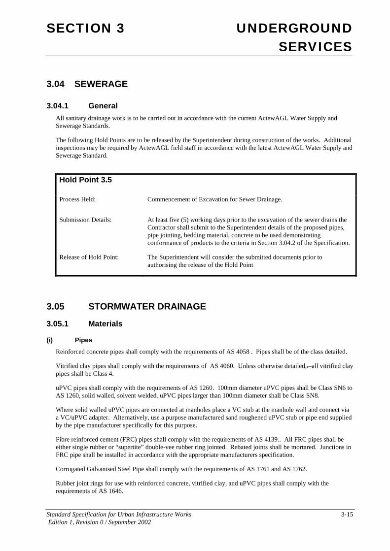
3.04.1 General All sanitary drainage work is to be carried out in accordance with the current ActewAGL Water Supply and Sewerage Standards.
The following Hold Points are to be released by the Superintendent during construction of the works. Additional inspections may be required by ActewAGL field staff in accordance with the latest ActewAGL Water Supply and Sewerage Standard.
Hold Point 3.5
Process Held: Commencement of Excavation for Sewer Drainage.
Submission Details: At least five (5) working days prior to the excavation of the sewer drains the Contractor shall submit to the Superintendent details of the proposed pipes, pipe jointing, bedding material, concrete to be used demonstrating conformance of products to the criteria in Section 3.04.2 of the Specification.
Release of Hold Point: The Superintendent will consider the submitted documents prior to authorising the release of the Hold Point
3.05 STORMWATER DRAINAGE
3.05.1 Materials
(i) Pipes
Reinforced concrete pipes shall comply with the requirements of AS 4058 . Pipes shall be of the class detailed.
Vitrified clay pipes shall comply with the requirements of AS 4060. Unless otherwise detailed,. all vitrified clay pipes shall be Class 4.
uPVC pipes shall comply with the requirements of AS 1260. 100mm diameter uPVC pipes shall be Class SN6 to AS 1260, solid walled, solvent welded. uPVC pipes larger than 100mm diameter shall be Class SN8.
Where solid walled uPVC pipes are connected at manholes place a VC stub at the manhole wall and connect via a VC/uPVC adapter. Alternatively, use a purpose manufactured sand roughened uPVC stub or pipe end supplied by the pipe manufacturer specifically for this purpose.
Fibre reinforced cement (FRC) pipes shall comply with the requirements of AS 4139.. All FRC pipes shall be either single rubber or “supertite” double-vee rubber ring jointed. Rebated joints shall be mortared. Junctions in FRC pipe shall be installed in accordance with the appropriate manufacturers specification.
Corrugated Galvanised Steel Pipe shall comply with the requirements of AS 1761 and AS 1762.
Rubber joint rings for use with reinforced concrete, vitrified clay, and uPVC pipes shall comply with the requirements of AS 1646.

SECTION 3 UNDERGROUND SERVICES
Standard Specification for Urban Infrastructure Works 3-16 Edition 1, Revision 0 / September 2002
All reinforced concrete and vitrified clay stormwater pipes up to and including 375mm diameter shall be rubber ring jointed. All rubber ring jointed pipes shall be flexible jointed at sumps and manholes to the details shown on the drawings. All reinforced concrete stormwater pipes up to and including 675mm diameter located under roadways shall be rubber ring jointed.
All galvanised steel pipe is to be laminated on the inside and outside with a heavy gauge polymer film by qualified laminating specialists in accordance with AASHTO M-246 and ASTM A-742.
If not specified, pipes 750mm diameter or greater under roadways may be flush jointed with external EB/S sand Bands to the pipe manufacturers specification. The correct position of the external bands shall be marked on each pipe prior to installation to enable checking of the correct fitting of the bands after installation. If not specified, pipes larger than 375mm diameter and not located under roadways may be flush jointed.
Pipes shall be manufactured under an approved quality assurance system. Pipes shall only be used if they have the necessary information clearly marked on them to identify the manufacturer, class of pipe, date of manufacture, batch number, pipe size and inspection status.
(ii) Precast Reinforced Concrete Box Culverts
Small precast reinforced concrete box culverts up to 1200mm x 900mm shall comply with the requirements of AS 1597.1. Each batch of culvert sections shall be subjected to the proof loading test as prescribed in Section 3.2 of AS 1597.1.
Large precast reinforced box culverts from 1500mm to 4200mm span and 4200mm height, including all link slabs shall comply with the requirements of AS 1597.2.
Precast reinforced concrete box culverts greater than 1200mm x 900mm shall be designed for T44 loadings in accordance with AUSTROADS Bridge Design Code.
Box culvert sections of size equal to or larger than 600mm x 450mm shall be fitted with suitable attachments for lifting gear.
Culverts shall be manufactured under an approved Quality Assurance System. Culverts shall only be used if they have the necessary information clearly marked on them to identify the manufacturer, date of manufacture, batch number, culvert dimensions and inspection status.
(iii) Bedding and Pipe Support Material
Bedding and pipe support material shall be in accordance with AS 3725. Unless shown on the drawings the pipe support type shall be Type HS3 under roads, paths and driveways, and H2 elsewhere.
Material for bedding, haunch and side zones shall consist of granular material with a Plasticity Index of less than 6 (AS 1289.3.3.1) and coarse particle size distribution (AS 1289.3.6.1) as prescribed in Table 3.6.
Table 3.4
Sieve Size Percent Passing
Bedding and Haunch Zones
19.0 mm 100
2.36 mm 50 to 100
0.60 mm 20 to 90

SECTION 3 UNDERGROUND SERVICES
Standard Specification for Urban Infrastructure Works 3-17 Edition 1, Revision 0 / September 2002
Sieve Size Percent Passing
0.30 mm 10 to 60
0.15 mm 0 to 25
0.075 mm 0 to 10
Side Zone
75 mm 100
9.5 mm 50 to 100
2.36 mm 30 to 100
0.60 mm 15 to 50
0.075 mm 0 to 25
Crushed recycled building materials may be used as a bedding material and side support material, provided it meets the requirements of Table 3.6. The Contractor shall obtain sample coarse particle size distributions from the manufacturer which are representative of the material to be used on site and submit them to the Superintendent for approval prior to use.
(iv) Concrete
Concrete, reinforcement and formwork for drainage structures shall comply with the requirements of Section 15 of this Specification . Minimum strength shall be 32 MPa for manholes (including covers) and similar structures and 20 MPa for scour stops, concrete bedding and encasement.
(v) Cement Mortar
Cement mortar shall comply with the requirements of AS 2701.
Hold Point 3.6
Process Held: Commencement of Excavation for Stormwater Drainage.
Submission Details: At least five (5) working days prior to the excavation of the stormwater drains the Contractor shall submit to the Superintendent details of the proposed pipes, box culverts, bedding material, concrete to be used demonstrating conformance of products to the criteria in Section 3.05.1 of the Specification.
Release of Hold Point: The Superintendent will consider the submitted documents prior to authorising the release of the Hold Point

SECTION 3 UNDERGROUND SERVICES
Standard Specification for Urban Infrastructure Works 3-18 Edition 1, Revision 0 / September 2002
3.05.2 Pipe Bedding and Side Support Unless otherwise shown on the Contract drawings, the pipes shall be laid in trench conditions. The support type and bedding and side support material described in this section is for trench conditions. If embankment conditions apply then refer to AS 2566 for uPVC pipes and AS 3725 for concrete pipes.
If not shown on the Contract drawings, the pipe support for concrete pipes shall be Type HS3 for all pipes located under roads, paths and driveways, and Type H2 elsewhere.
The pipe bedding for concrete stormwater pipes with Type H2 and HS3 support shall be placed to the required thickness of 100mm for pipe nominal diameter less than or equal to 1500mm or 150mm for pipe nominal diameter greater than 1500mm.
If not shown on the Contract drawings, the pipe bedding for uPVC pipes shall be in accordance with AS2032.
The haunch zone shall extend from the top of the bedding material up to 0.3 times the pipe outside diameter. The haunch zone material shall be the same as for bedding as specified in Table 3.6, compacted to 90% MMDD for Type H2 support and DI 70% for Type HS3 support.
The side zone for Type HS3 support shall extend from the top of the haunch zone material up to 0.7 times the pipe outside diameter. The side zone material shall comply with the grading in Table 3.6, compacted in maximum 150mm thick layers to 90% Modified Maximum Dry Density or DI 70%.
3.05.3 Laying and Jointing of Pipes and Culverts
(i) Culverts
Unless otherwise specified, where pipe or box culverts are to be laid under new road embankments, they shall be constructed before filling has progressed to a height greater than 1 m above top of pipe or box section. Generally, embankments shall be filled to subgrade level prior to trenching and pipes laid under trench conditions.
(ii) Pipes
Unless otherwise specified, commence laying pipes at the outlet end and proceed upstream.
Remove all foreign matter from inside and outside of pipes before laying.
Lay and joint pipes to the lines, grades and levels shown on the drawings. Ensure that pipe barrels bear uniformly on the prepared bedding over their full length. Keep pipelines clear of debris and obstructions as laying and jointing proceeds.
For interface of pipes with stormwater structures such as manholes, sumps, anchor blocks and special structures refer to ACT Government joints.
For curved pipelines, the minimum radius for standard pipes shall be according to the manufacturers recommendation. When splayed pipes are used the splays shall be either factory formed or splays formed in the field by the cutting of standard pipes. The length of field splayed pipes at the outside spring line shall be 1200mm maximum and 900mm minimum. Unless detailed otherwise for field splayed pipes the joints are to be bandaged joints as shown on Urban Stormwater Manual – Standard Engineering Practices, Drawing ST-0018.
Plug lifting holes in pipes with cement mortar or manufactured plugs before commencing backfilling.
Where detailed lay stormwater pipes to a curved alignment, concentric with the curved line. Curved pipelines shall be made by either deflections at each joint or by the use of splayed pipes as specified on the Contract drawings. Standard pipes shall use either flush joints or rubber ring. Joint deflections shall have the same deflection at each joint.

SECTION 3 UNDERGROUND SERVICES
Standard Specification for Urban Infrastructure Works 3-19 Edition 1, Revision 0 / September 2002
Curved lines in FRC pipes can be achieved by the use of either Standard 11.25 degree bends or by deflecting the pipes at the joints. The maximum deflection shall be in accordance with the manufacturers recommendations.
When using a rubber ring jointing system, form joints by placing ring evenly over the pipe spigot without twist and rolling it into the socket. Spigots shall always be inserted squarely into sockets. If line is to be curved, deflect pipe after making joint. Rubber ring joints in 100mm and 150mm diameter vitrified clay pipes shall comply with the requirements of AS 1646..
Pack mortar joints with a 2:1 sand:cement mortar of caulking consistency. Strike off neatly with a steel trowel. Use loose collar or bandage joints on all pipes with butt ends and wherever pipe ends have been cut or broken. Bandage joints shall be as detailed on the drawings.
On lines with gradients exceeding 7%, provide concrete scour stops at maximum intervals of five (5) m throughout the length. Each block shall be 300mm wide (measured parallel to pipe axis), be let into the solid trench sides and bottom by 150mm and extend to 75mm above crown of pipe. A flexible joint shall be used either side of the scour stop in accordance with Urban Stormwater Manual – Standard Engineering Practices, Drawing ST-0018.
Concrete encasement, if required, shall comply with Clause 3.04.3. The Superintendent may approve the substitution of ductile iron pipes, laid and jointed as specified for water mains, in lieu of concrete encasement.
Install uPVC pipes in accordance with AS 2032, or as shown on the Contract drawings. Deflections of rubber ring joints on uPVC pipes are not permitted. Curvature is to be obtained by bending the pipe whilst maintaining the position of the joint in the trench.
(iii) House Connections
Pipes used for house connection branches shall be of spigot and socket rubber ring joint type and be made of reinforced concrete or vitrified clay. uPVC Class SN6, solid walled solvent welded pipes may also be used.
Subject to approval other material may be used, provided it meets the requirements of this specification.
Install branches for future extensions and house connections in main drains and manholes as detailed.
Blank off branches with rubber ring jointed plugs held in place with metallic spring clips. Where uPVC pipes are used, blank off tie connection with uPVC end cap.
Service tie locations shall be identified with an approved plastic tape. The tape shall be nominally 75mm wide and coloured in accordance with AS 2648.1. The tape shall be secured to the end of the tie and brought vertically to the surface and attached to a marker stake. The marker shall protrude 300mm above the finished surface.
(iv) Box Culverts
Lay precast box culverts on a reinforced concrete invert slab which may be precast or cast-in-situ. Concrete for cast-in-situ slabs shall be in accordance with the requirements of Section 15 of this Specification and shall be strength grade N25 to AS 3600.
Align culvert sections to provide a continuous straight waterway without discontinuity at joints. Joints shall be close butted and sealed with a suitable bituminous or mastic sealant. Lay sections on a 1: 1 fine sand:cement slurry unless shown otherwise on the drawings.
When two or more rows of parallel box sections are to be constructed together, they shall be laid on a single cast insitu slab. Provide clearance as detailed between lines and fill space with mortar or grout,
(v) Connection to Existing Facilities
Where detailed connect drains to existing manholes, sumps or pipes. Break out existing structures to the minimum extent necessary and reinstate on completion of the connection.

SECTION 3 UNDERGROUND SERVICES
Standard Specification for Urban Infrastructure Works 3-20 Edition 1, Revision 0 / September 2002
3.05.4 Drainage Structures
(i) General
Construct manholes, sumps, end walls and other structures as detailed.
Bench bases as detailed and finish smoothly to minimise turbulence of flow.
Where subsoil drains discharge into drainage structures the penetration through the wall shall be sleeved with 100mm diameter uPVC pipes.
(ii) Formwork
Formwork shall comply with the requirements of Section 15 of this Specification. Both internal and external surfaces of walls shall be formed. However, where the depth of the structure and nature of the ground permit, walls may be cast without external forms provided the ground is undisturbed, that it is trimmed to an even vertical surface and that wall thickness is increased by at least 50mm over that detailed. No additional payment will be allowed for this alternative procedure. External formwork shall be used for the top 300mm of manholes and sumps in all cases. Formwork shall be used for both faces of end walls.
Construct manholes and sumps with blockouts for connection of future pipelines as detailed.
(iii) Covers
All stormwater manhole covers shall be marked with the letters "SW".
In paved areas and elsewhere as detailed, provide manholes with heavy duty covers and frames at least equivalent to Gatic heavy circular covers with 600mm clear opening installed as specified in Clause 3.04.4.
(iv) Top Levels
Cover levels where shown for drainage structures are for guidance to the Contractor only. The Contractor is responsible for the establishment of accurate levels in order to comply with the following requirements. Finish manhole covers flush with pavement in paved areas, 25mm above finished surface in landscaped areas and 75mm above natural surface elsewhere.
(v) Backfilling
Backfill around drainage structures as specified for the adjacent pipe trench. Backfilling to structures abutting kerbs or pavement edges shall be as specified for trenches in paved areas.
(vi) Alterations to Existing Structures
Where existing structures are to be raised or lowered, break out sufficient of the walls to expose reinforcement and to allow at least 150mm of new concrete below the new cover or frame. Splice new reinforcement to old as necessary, form and place concrete as specified for new structures.
(vii) Galvanising of Mild Steel Fixtures
Where shown on the drawings, mild steel fixtures including grates, frames, step irons, ladders, etc., shall be hot dip galvanised. Galvanising shall comply with the requirements of AS 1214 or AS 1650, as appropriate.
The average coating to items other than threaded fasteners shall be 600 g/m2. Threaded fasteners shall have an average coating of 375 g/m2. Surplus material shall be removed from threads of bolts so that no recutting is required.

SECTION 3 UNDERGROUND SERVICES
Standard Specification for Urban Infrastructure Works 3-21 Edition 1, Revision 0 / September 2002
(viii) Sealed Sumps
Sealed sumps, where shown on drawings shall be constructed as for standard sumps but without an opening for surface water.
(ix) Endwalls
When backfilling adjacent to endwalls provide a layer of permeable material adjacent to weepholes complying with the requirements of Clause 3.06.1 for combined filter medium.
Where shown on the drawings construct a protective fence at each endwall as detailed on the relevant standard drawing. All fittings shall be galvanised as specified in Item (vii) above.
(x) Stone Pitching
Stone pitching shall be constructed as specified in Clause 8.03.
(xi) Precast Concrete Manholes
The insitu concrete bases for precast manholes shall be constructed with a 140mm x 75mm deep ring incorporated to facilitate the seating of the precast circular manhole components. The minimum concrete thickness between the invert of the seating ring and the crown of the highest pipe shall be 25mm.
This ring shall be filled with a 3:1 sand cement mortar prior to the placement of the precast components and trowelled off after the placement of the components.
The construction of the precast manhole and the insitu base shall be in accordance with ACT Water Supply and Sewerage Standards, Drawing WSS057 except that the precast cover and ring shall be in accordance with ACT Government Urban Stormwater – Standard Engineering Practices standard drawing ST-0017.
(xii) Sandbag Headwall
The Contractor shall supply and place sandbags of minimum size 450mm x 300mm x 150mm filled with clean sand mixed with normal Portland cement at the ratio of 1 part cement to 12 parts sand by weight.
(xiii) Reinforced Concrete Structures
This shall include special chambered manholes and structures, headwalls and base slabs which require steel reinforcing. The placed steel shall be inspected by the Superintendent prior to the concrete being poured.
Hold Point 3.7
Process Held: Placement of Concrete in Reinforced Concrete Structures
Submission Details: A Certificate of compliance signed by the Contractor covering the installation of reinforcement (ie cover, spacing, splicing, etc) and compliance of formwork in accordance with the Contract requirements.
Release of Hold Point: The Superintendent will consider the submitted documents and may inspect the works prior to authorising the release of the Hold Point.

SECTION 3 UNDERGROUND SERVICES
Standard Specification for Urban Infrastructure Works 3-22 Edition 1, Revision 0 / September 2002
3.05.5 Conformance Criteria
(i) Materials
a) Pipes and Culverts
The Contractor's conditions of purchase of pipes and culverts shall require the provision of access to the manufacturers facilities for the Superintendent to enter the supplier's factory and place of testing to observe the processes of manufacture and testing.
The Contractor shall obtain copies of test certificates for stormwater pipes from the manufacturer which are readily identifiable with the batch they represent. A copy of the test certificates shall be provided to the Superintendent upon request.
b) Bedding
The Contractor shall obtain a copy of the Suppliers grading tests that is indicative of the material supplied. A copy of this test certificate shall be provided to the Superintendent upon request.
The Contractor shall arrange for testing of bedding material by an independent tester in accordance with Table 3.8. A copy of the test certificates shall be provided to the Superintendent upon request.
c) Concrete
The Contractor shall obtain a copy from each supplier of their concrete mix design for stormwater structures. A copy of this certificate shall be made available to the Superintendent upon request.
The Contractor shall arrange for testing of the supplied concrete by an independent tester in accordance with Table 3.8. A copy of the test certificates shall be provided to the Superintendent upon request.
(ii) Compaction Conformance
Compaction conformance requirements for work carried out under this Clause of the Specification are described above and summarised in Table 3.5.
Conformance of bedding and support material is conditional upon that it achieving the specified compaction requirements.
Table 3.5
Item Compaction Requirement
Haunch zone – not under Roads, Paths and Driveways (Type H2 support)
90% Relative Density
Haunch zone- under Roads, Paths and Driveways (Type HS3 support)
Density Index of 70%
Side zone – under Roads, Paths and Driveways (Type HS3 support)
90% Modified Maximum Dry Density, or
Density Index 70%
SECTION 3 UNDERGROUND SERVICES
Standard Specification for Urban Infrastructure Works 3-23 Edition 1, Revision 0 / September 2002
(iii) Tolerances
Pipelines shall be within 50mm of design line and level at all points where design grade exceeds 1% and within 20mm of line and level for grades flatter than 1%.
No adverse grades will be permitted on any section of the pipeline.
The Contractor shall test completed uPVC stormwater pipes for ovality. Pipes 150mm diameter and above are to be tested using a proving tool to a design approved by the Superintendent. The proving tool shall be constructed using laminated or solid hardwood or other suitable approved durable material machined to shape and size as specified and drilled through the centre to take a galvanising rod with eye bolts at each end. The proving tool diameter shall be the mean bore of the pipe as specified by the Manufacturer minus 6% with a tolerance of +/- 0.1mm.
The diameter of proving tool specified above shall apply to a minimum length of 80mm.
The test of ovality shall be undertaken by the Contractor in the presence of the Superintendent’s representative at least 14 days after compaction of completed backfill. A Stormwater Authority representative may request to be present at the testing. Pipes not meeting the above criteria shall be rectified at the Contractors expense and retested.
(iv) Sampling and Testing
All laboratory testing of work carried out under this Section of the Specification shall be performed in accordance with procedures specified herein.
Work under this Specification shall be subdivided into lots or discrete work areas. The Superintendent shall have the right to reject a lot which is visually non-homogeneous and/or non-representative.
The specified testing shall be taken at the random test locations established in each lot in accordance with the specified minimum testing frequency in Clause 2.09.4. Prior to testing the Contractor shall work the lot to ensure uniform moisture content and compaction of all material within the lot.
The test/s then taken shall be considered to represent the total volume of material placed within the lot.
The compaction requirements specified in Table 3.7 are minimum requirements. When density tests are carried out on a lot, the number of results falling below the specified value shall not exceed the limits set out in Table 2.4.
(v) Frequency of Testing
The frequency of testing shall be appropriate to verify conformity and shall not be less than that stated in Table 3.8 unless otherwise approved by the Superintendent. Where no minimum frequency of inspection or testing is stated, the Contractor shall nominate appropriate frequencies in their Inspection and Test Plan(s).
The Contractor shall include in the management review of the Quality System, a review of the appropriateness of the frequency of testing nominated in the Inspection and Test Plan(s). Such review shall take into account the frequency of nonconformity detected, including non-conformities remedied by simple reworking.

SECTION 3 UNDERGROUND SERVICES
Standard Specification for Urban Infrastructure Works 3-24 Edition 1, Revision 0 / September 2002
Table 3.6
Clause
Characteristic Analysed Test Method Minimum Frequency Of Testing
Compaction
3.05.1 Compaction and moisture content for bedding and side support
AS 1289.5.2.1; AS 1289.5.4.1
One test per line or per 50 linear metres or part thereof.
Bedding Material Properties
3.05.1 Bedding Material Grading AS 1289.3.6.1 One per 100m3 or part thereof
3.05.1 Bedding Material Plasticity AS 1289.3.3.1 One per 100m3 or part thereof
Concrete Compressive Strength
3.05.1 Concrete slump AS 1012.3 One per batch of concrete delivered for reinforced concrete works.
3.05.1 Concrete Compressive Strength
AS 1012.9 One pair of test specimens per 50m3 of concrete with a minimum of one pair per individual reinforced structure unless otherwise approved by the Superintendent.
Pipe Ovality
3.05.5 Pipe Ovality Clause 3.05.5 One test per pipe line.
(vi) Nonconforming Work
(a) General
A nonconformance report shall be submitted to the Superintendent for any nonconformance detected. Work shall not proceed on any nonconforming item until the Superintendent has approved the disposition for the nonconformance.
(b) Nonconforming Compaction
Where a lot is nonconforming for compaction on the basis of inspection or test results, further compactive effort shall be applied to the lot or nominated parts of the lot until the specified standard is achieved. Scarify the area for the full depth of the layer and add water as necessary. Mix mechanically to ensure uniform distribution of moisture before commencing rolling.
(c) Nonconforming Concrete
Where a lot is nonconforming for compressive strength on the basis of inspection or test results, the Superintendent will consider the results and may instruct the structure to be demolished and reconstructed or remedial works to be undertaken. This work shall be at the Contractors expense.
SECTION 3 UNDERGROUND SERVICES
Standard Specification for Urban Infrastructure Works 3-25 Edition 1, Revision 0 / September 2002
3.05.6 Acceptance by Stormwater Authority
(i) Final Inspection
Pipes and structures shall be flushed out and cleaned of debris, si I t etc. before final inspection. Water for flushing may be obtained from the Contractor's temporary tapping on-site. Water shall not be drawn from hydrants.
Attention is drawn to the need for compliance with the Water Pollution Act.
Final acceptance is that stage when the Superintendent is satisfied that the work meets all of the requirements of the Contract including the requirements of the relevant Acts.
Liaise with the Superintendent who will arrange for a final inspection when the stormwater lines have been checked and backfilled, manholes and sumps are complete and lines have been flushed clean.
Acceptance will be subject to the rectification of any defects notified by the Superintendent. Allow sufficient notice of readiness for inspection.
The Certificate of Practical Completion will not be issued until final acceptance has been advised by the Superintendent.
No section of the stormwater system will be accepted until all contributing lines have been completed and connected, bituminous surfacing of contributing roads has been completed and all unpaved areas of the site have been completed as required by the documents.
3.06 SUBSOIL DRAINS
3.06.1 Materials
(i) Pipes
Unless otherwise detailed, pipes for subsoil drains shall be 100mm diameter corrugated perforated plastic drainage pipe Class 1000 complying with the requirements of AS 2439.
Perforated or slotted pipes of other material including uPVC and FRC may be accepted as an alternative subject to compliance with the relevant sections of AS 2439.
Geocomposite plastic filter strips may also be accepted as an alternative for subsoil drainage subject to compliance with the relevant sections of AS2439. The filter strip may be either a rigid or flexible plastic core with slots or openings and shall be totally encased in a specially manufactured and fitted geotextile fabric. The Contractor shall provide copies of certificate of compliance from the manufacturer verifying that the filter strip satisfies the requirements of AS2439 and details of manufacturers recommended construction method for the filter strip including connections to structures.
SECTION 3 UNDERGROUND SERVICES
Standard Specification for Urban Infrastructure Works 3-26 Edition 1, Revision 0 / September 2002
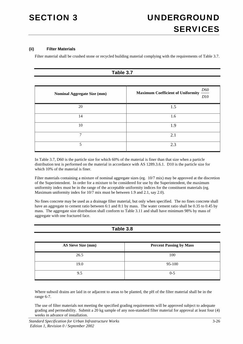
(ii) Filter Materials
Filter material shall be crushed stone or recycled building material complying with the requirements of Table 3.7.
Table 3.7
Nominal Aggregate Size (mm) Maximum Coefficient of Uniformity
10
60
D
D
20 1.5
14 1.6
10 1.9
7 2.1
5 2.3
In Table 3.7, D60 is the particle size for which 60% of the material is finer than that size when a particle distribution test is performed on the material in accordance with AS 1289.3.6.1. D10 is the particle size for which 10% of the material is finer.
Filter materials containing a mixture of nominal aggregate sizes (eg. 10/7 mix) may be approved at the discretion of the Superintendent. In order for a mixture to be considered for use by the Superintendent, the maximum uniformity index must be in the range of the acceptable uniformity indices for the constituent materials (eg. Maximum uniformity index for 10/7 mix must be between 1.9 and 2.1, say 2.0).
No fines concrete may be used as a drainage filter material, but only when specified. The no fines concrete shall have an aggregate to cement ratio between 6:1 and 8:1 by mass. The water cement ratio shall be 0.35 to 0.45 by mass. The aggregate size distribution shall conform to Table 3.11 and shall have minimum 98% by mass of aggregate with one fractured face.
Table 3.8
AS Sieve Size (mm) Percent Passing by Mass
26.5 100
19.0 95-100
9.5 0-5
Where subsoil drains are laid in or adjacent to areas to be planted, the pH of the filter material shall be in the range 6-7.
The use of filter materials not meeting the specified grading requirements will be approved subject to adequate grading and permeability. Submit a 20 kg sample of any non-standard filter material for approval at least four (4) weeks in advance of installation.

SECTION 3 UNDERGROUND SERVICES
Standard Specification for Urban Infrastructure Works 3-27 Edition 1, Revision 0 / September 2002
(iii) Geotextile
Filter fabric shall be a non woven type with the following properties:
(a) Elongation
The maximum puncture strength when determined in accordance with AS3706.4 shall be equal to or greater than 30%.
(b) Grab Strength
The mean grab strength shall be greater than 500N determined in accordance with AS 2001.2.3 Method B
(c) Tear
Tear strength shall be greater than 180N determined in accordance with AS 3706.3.
(d) Filtration
The geotextile shall have a flow rate greater than or equal to 50 litres / m2 /second and permittivity of greater than or equal to 0.5 / second determined in accordance with AS 3706.9.
Hold Point 3.8
Process Held: Commencement of Excavation for Sub-soil Drainage.
Submission Details: At least five (5) working days prior to the excavation of the subsoil drains the Contractor shall submit details of the corrugated perforated plastic pipe, geotextile, and filter material demonstrating conformance of products to the criteria in Section 3.06.1 of the Specification.
Release of Hold Point: The Superintendent will consider the submitted documents prior to authorising the release of the Hold Point
3.06.2 Trenches Unless otherwise detailed or directed, locate trenches for longitudinal drains so that the pipe centre line will be either directly under the kerb or immediately in front of the kerb. Unless otherwise detailed, trenches for corrugated plastic pipe subsoils shall be a minimum 200mm wide and 600mm deep under the Subgrade unless otherwise shown on the drawings.
Trenches shall generally be graded at the same grade as the road. Trenches shall be graded such that the subsoil drains can discharge into a drainage structure.
The bottom of the trench shall be graded to remove any localised ponding greater than 20mm. If the trench is over excavated or localised ponding would occur, the trench floor shall be filled with non-porous subgrade material and compacted to 90% Modified Maximum Dry Density.

SECTION 3 UNDERGROUND SERVICES
Standard Specification for Urban Infrastructure Works 3-28 Edition 1, Revision 0 / September 2002
The Superintendent shall inspect the trenches prior to bedding. Any unsuitable material in the base of the trench shall be removed and replaced with non-porous subgrade material compacted to 90% Modified Maximum Dry Density.
3.06.3 Bedding, Laying and Jointing The stockpiling and handling of filter material shall be carefully controlled so that the filter is not contaminated by soil or other deleterious matter. Filter material so contaminated shall not be used in subsoil construction.
Bed and lay pipes as detailed. Unless otherwise detailed or permitted, the minimum grade shall be 1%. Unless detailed otherwise the bedding material shall be 50mm thick. Lay corrugated polyethylene pipes with one line of slots at the bottom. Joint pipes in accordance with manufacturer's instructions. Joints are to be kept to a minimum number. Pipe joints shall be made by external joint coupling. The end of the pipe shall be capped.
Place filter material in trench so as to avoid segregation. When placing two-zoned filters alongside pipes place a temporary shutter vertically in the trench to prevent mixing.
Compact filter material to density index of 70. The first layer above the pipe shall be 300mm deep. The filter material shall be placed and compacted in such a way as to ensure that the pipe does not move and is not damaged.
All faces of filter material in contact with topsoil or similar fine grained finish shall be covered geotextile.
In trenches with hard rock bases, the Superintendent may relax the requirement for trimming the base, subject to there being no adverse effect on overall drain performance.
3.06.4 Finishing
(i) High Ends and Flushing Points
High ends and flushing points of drains shall be turned up and capped at the surface with a cast iron box with hinged lid set in a concrete surround 300mm square by 150mm deep.
Where a drain is under a pavement, risers shall be diverted from the line of the drain so that the cover will be at the outside edge of the nearer shoulder or behind the nearer kerb. Surround risers with compacted filter medium.
(ii) Outlets
Discharge drains to sumps, stormwater manholes, pipes or to the surface as detailed or as directed.
Where invert levels are not detailed, the obvert of the subsoil drain shall not be lower than the highest obvert of other pipes at the point of connection.
Where discharge is to the surface or an open drain, construct an endwall as detailed in standard drawings.
Fit wire guards to end walls and manhole connections as detailed in standard drawings.
(iii) Silt Traps
Install silt traps as detailed at maximum intervals of 160m and constructed as specified in Clause 3.05.4 for drainage structures.
(iv) Marking and Recording
Mark risers on all subsoil drains by stencilling "SS" in letters 50mm high on concrete surrounds to cast iron boxes, as per drawing DS6-05
Provide a plan to the Superintendent showing the locations and levels of subsoil drains as constructed.

SECTION 3 UNDERGROUND SERVICES
Standard Specification for Urban Infrastructure Works 3-29 Edition 1, Revision 0 / September 2002
(v) Proving
Demonstrate that drains are clean and continuous on completion of all underground services including cabling and street lighting by passing a flexible rod or small ball through the drain, to the satisfaction of the Superintendent.
Install rodent proofing to outlets immediately on completion of proving.
3.06.5 Conformance Criteria
(i) Materials
(a) Pipes
The Contractor shall obtain copies of test certificates for corrugated perforated plastic drainage pipe from the manufacturer which are readily identifiable with the batch they represent. A copy of the test certificates shall be provided to the Superintendent upon request.
(b) Geotextile
The Contractor shall obtain copies of test certificates for geotextile material from the manufacturer which are readily identifiable with the batch they represent. A copy of the test certificates shall be provided to the Superintendent upon request.
(c) Filter Material
The Contractor shall obtain a copy of the Suppliers grading tests that is indicative of the material supplied. A copy of this test certificate shall be provided to the Superintendent upon request.
The Contractor shall arrange for testing of filter material by an independent tester in accordance with Table 3.8. A copy of the test certificates shall be provided to the Superintendent upon request.
(ii) Compaction Conformance
Compaction conformance requirements for work carried out under this Clause of the Specification are described above and summarised in Table 3.12.
Conformance of filter material is conditional upon that it achieving the specified compaction requirements.
Table 3.9
Item Compaction Requirement
Filter material Density Index of 70% non-cohesive material
(iii) Tolerances
Pipelines shall be within 50mm of design line and level and shall fall towards the outlet at all points.
(iv) Sampling and Testing
All laboratory testing of work carried out under this Section of the Specification shall be performed in accordance with procedures specified herein.

SECTION 3 UNDERGROUND SERVICES
Standard Specification for Urban Infrastructure Works 3-30 Edition 1, Revision 0 / September 2002
Work under this Specification shall be subdivided into lots or discrete work areas. The Superintendent shall have the right to reject a lot which is visually non-homogeneous and/or non-representative.
The specified testing shall be taken at the random test locations established in each lot in accordance with the specified minimum testing frequency in Clause 2.09.4. Prior to testing the Contractor shall work the lot to ensure uniform moisture content and compaction of all material within the lot.
The test/s then taken shall be considered to represent the total volume of material placed within the lot.
The compaction requirements specified in Table 3.12 are minimum requirements. When density tests are carried out on a lot, the number of results falling below the specified value shall not exceed the limits set out in Table 2.4.
(v) Frequency of Testing
The frequency of testing shall be appropriate to verify conformity and shall not be less than that stated in Table 3.13 unless approved otherwise by the Superintendent. Where no minimum frequency of inspection or testing is stated, the Contractor shall nominate appropriate frequencies in their Inspection and Test Plan(s).
The Contractor shall include in the management review of the Quality System, a review of the appropriateness of the frequency of testing nominated in the Inspection and Test Plan(s). Such review shall take into account the frequency of nonconformity detected, including nonconformities remedied by simple reworking.
Table 3.10
Clause
Characteristic Analysed Test Method Minimum Frequency Of Testing
Compaction
3.06.3 Compaction and moisture content for filter material
AS1289.5.4.1; AS 1289.5.4.1
One test per line or per 150 linear metres or part thereof.
Filter Material Properties
3.06.1 Filter Material Grading AS 1289.3.6.1 One per 100m3 or part thereof
Geotextile
3.06.1 Puncture Strength AS 3706.4 Provide copy of Manufacturer’s Certificate
3.06.1 Grab Strength AS 2001.2.3 Provide copy of Manufacturer’s Certificate
3.06.1 Tear Strength AS 3706.3 Provide copy of Manufacturer’s Certificate
3.06.1 Filtration and Permeability AS 3706.9 Provide copy of Manufacturer’s Certificate

SECTION 3 UNDERGROUND SERVICES
Standard Specification for Urban Infrastructure Works 3-31 Edition 1, Revision 0 / September 2002
(vi) Nonconforming Work
(a) General
A nonconformance report shall be submitted to the Superintendent for any nonconformance detected. Work shall not proceed on any nonconforming item until the Superintendent has approved the disposition for the nonconformance.
(b) Nonconforming Compaction
Where a lot is nonconforming for compaction on the basis of inspection or test results, further compactive effort shall be applied to the lot or nominated parts of the lot until the specified standard is achieved. Scarify the area for the full depth of the layer and add water as necessary. Mix mechanically to ensure uniform distribution of moisture before commencing rolling.
3.07 CONDUITS
3.07.1 General The works covered by this Section of the Specification includes the installation of conduits for telecommunications, gas, electrical, and irrigation services both under road pavements and within the road verge area. Trenching for conduits shall be in accordance with the ‘Underground Services in a Shared Trench’ agreement between the respective Service Authorities. A copy of this agreement may be obtained from the Service Authorities.
Prior to excavation of trenches for services conduits the Contractor shall liaise with the Service Authorities to confirm the servicing and co-ordination requirements of the Authorities.
3.07.2 Materials Unless otherwise specified, conduits for gas shall be heavy duty sewer uPVC pipe complying with requirements of AS2053 and shall be of the diameter specified.
Unless otherwise specified, conduits for telecommunications and TransACT shall be heavy duty uPVC conforming to requirement of AS2053 and coloured white and of the diameter specified.
Unless otherwise specified, conduits for electricity shall be heavy duty uPVC conforming to requirement of AS2053 and coloured orange and of the diameter specified.
Only standard pits specified and supplied by each service authority shall be used.

SECTION 3 UNDERGROUND SERVICES
Standard Specification for Urban Infrastructure Works 3-32 Edition 1, Revision 0 / September 2002
Hold Point 3.9
Process Held: Commencement of Excavation for Conduits.
Submission Details: At least five (5) working days prior to the excavation of conduits the Contractor shall submit to the Superintendent details of the proposed pipes, pipe jointing, pipe colour, bedding material to be used demonstrating conformance of products to the criteria in Section 3.07.1 of the Specification.
Release of Hold Point: The Superintendent will consider the submitted documents prior to authorising the release of the Hold Point
3.07.3 Trenching The Contractor shall set out the location of all conduits, pits and bends and shall notify the Superintendent prior to excavation.
The Contractor shall excavate the trenches for conduits to the depths required to achieve the minimum cover specified in Table 3.1 for each particular service conduit, or the required depths where shown on the Contract drawings. Widths of trenches will vary depending on the number and type of services in the trench. The trench width shall be in accordance with the ‘Underground Services in a Shared Trench’ agreement.
The trench shall be at a graded at a minimum of 0.5% fall. Conduits under roads and other objects shall project at least 1000mm beyond obstructions such as kerb, subsoil drains, stormwater and water mains. The trench shall be excavated beyond these obstructions.
The locations of any pits or bends shall be approved by the Superintendent prior to excavation. The Contractor shall perform any additional excavation, bedding and backfilling required for services pits and structures.
The locations of all conduits shall be recorded and added to WAE drawings.
3.07.4 Installation Conduit joints shall be solvent welded connections, unless otherwise approved by the Service Authority
Unless specified otherwise in the Contract drawings or by the Service Authorities, bedding and backfilling shall be in accordance with Section 3.03.8. Bedding to each conduit under a road shall consist of suitable bedding and side support zone in accordance with AS 2032. The Contractor shall supply and place bedding and backfill material between each separate service conduit to the satisfaction of the Service Authorities. Where required by the Service Authorities the Contractor shall supply and install warning tape above the conduits.
The location of each service conduit within the trench shall be in accordance with the ‘Underground Services in a Shared Trench’ agreement.
The location of pits shall be such as to permit changes in direction of cabling to occur at pits wherever possible.
Where bends in conduits are required only long radius bends shall be used. The total bending radii on a single run between two pits shall not exceed 90 degrees.
Conduits may be curved between pits generally to follow a curved road or structure but only one curve shall be permitted between two pits.

SECTION 3 UNDERGROUND SERVICES
Standard Specification for Urban Infrastructure Works 3-33 Edition 1, Revision 0 / September 2002
Conduits shall be capped with a non perishable removable cover prior to backfilling to prevent the entry of foreign material.
Install a 2.5mm diameter high tensile draw wire in each conduit length before sealing both ends. Draw wires shall be at least 1m longer than the conduit in which they are installed.
Where conduits cross kerb lines, their locations shall be marked by casting a letter 100mm high into the kerb. The letters used shall be “E” for electricity conduits, “G” for gas conduits and “T” for Telecommunications conduits.
3.07.5 Conformance Criteria
(i) Materials
The Contractor's conditions of purchase of pipes shall require the provision of access to the manufacturers facilities for the Superintendent to enter the supplier's factory and place of testing to observe the processes of manufacture and testing.
The Contractor shall obtain copies of test certificates for stormwater pipes from the manufacturer which are readily identifiable with the batch they represent. A copy of the test certificates shall be provided to the Superintendent upon request.
(ii) Compaction Conformance
Compaction conformance requirements for work carried out under this Clause of the Specification are summarised in Table 3.7 above.
Conformance of bedding and support material is conditional upon it achieving the specified compaction requirements.
(iii) Tolerances
Conduits shall be within 50mm of design line and no more than 20mm above minimum cover level at all points.
The Contractor shall test completed conduits for ovality. Pipes 100mm diameter and above are to be tested using a proving tool to a design approved by the Superintendent. The proving tool shall be constructed using laminated or solid hardwood or other suitable approved durable material machined to shape and size as specified and drilled through the centre to take a galvanising rod with eye bolts at each end. The proving tool diameter shall be the mean bore of the pipe as specified by the Manufacturer minus 6% with a tolerance of +/- 0.1mm.
The diameter of proving tool specified above shall apply to a minimum length of 80mm.
The test of ovality shall be undertaken by the Contractor in the presence of the Superintendent’s representative at least 14 days after compaction of completed backfill. A Service Authority representative may request to be present at the testing. Conduits not meeting the above criteria shall be rectified at the Contractors expense and retested.
(iv) Sampling and Testing
All laboratory testing of work carried out under this Section of the Specification shall be performed in accordance with procedures specified herein.
Work under this Specification shall be subdivided into lots or discrete work areas. The Superintendent shall have the right to reject a lot which is visually non-homogeneous and/or non-representative.
The specified testing shall be taken at the random test locations established in each lot in accordance with the specified minimum testing frequency in Clause 2.09.4. Prior to testing the Contractor shall work the lot to ensure uniform moisture content and compaction of all material within the lot.

SECTION 3 UNDERGROUND SERVICES
Standard Specification for Urban Infrastructure Works 3-34 Edition 1, Revision 0 / September 2002
The test/s then taken shall be considered to represent the total volume of material placed within the lot.
The compaction requirements specified in Table 3.7 are minimum requirements. When density tests are carried out on a lot, the number of results falling below the specified value shall not exceed the limits set out in Table 2.4.
(v) Frequency of Testing
The frequency of testing shall be appropriate to verify conformity and shall not be less than that stated in Table 3.8. Where no minimum frequency of inspection or testing is stated, the Contractor shall nominate appropriate frequencies in their Inspection and Test Plan(s).
The Contractor shall include in the management review of the Quality System, a review of the appropriateness of the frequency of testing nominated in the Inspection and Test Plan(s). Such review shall take into account the frequency of nonconformity detected, including non-conformities remedied by simple reworking.
(vi) Nonconforming Work
(a) General
A nonconformance report shall be submitted to the Superintendent for any nonconformance detected. Work shall not proceed on any nonconforming item until the Superintendent has approved the disposition for the nonconformance.
(b) Nonconforming Compaction
Where a lot is nonconforming for compaction on the basis of inspection or test results, further compactive effort shall be applied to the lot or nominated parts of the lot until the specified standard is achieved. Scarify the area for the full depth of the layer and add water as necessary. Mix mechanically to ensure uniform distribution of moisture before commencing rolling.
3.08 WATER SUPPLY MAINS All water supply work is to be carried out in accordance with the current ActewAGL Water Supply and Sewerage Standards.
The following Hold Points are to be released by the Superintendent during construction of the works. Additional inspections may be required by ActewAGL field staff in accordance with the latest ActewAGL Water Supply and Sewerage standard.
Hold Point 3.10
Process Held: Commencement of Excavation for Water Pipes.
Submission Details: At least five (5) working days prior to the excavation of the water pipes the Contractor shall submit to the Superintendent details of the proposed pipes, pipe jointing, bedding material, valves and fittings, concrete to be used demonstrating conformance of products to the criteria in Section 3.08.1 of the Specification.
Release of Hold Point: The Superintendent will consider the submitted documents prior to authorising the release of the Hold Point

SECTION 3 UNDERGROUND SERVICES
Standard Specification for Urban Infrastructure Works 3-35 Edition 1, Revision 0 / September 2002
Hold Point 3.11
Process Held: Placement of backfill material.
Submission Details: At least two (2) working day prior to acceptance testing. Completed section of water main with all joints exposed ready for pressure testing.
Release of Hold Point: The Superintendent will inspect the new pipes and fittings and observe the pressure testing prior to authorising the release of the Hold Point
3.09 WATER SERVICES
All water services work is to be carried out in accordance with the current ActewAGL Water Supply and Sewerage Standards.
The following Hold Points are to be released by the Superintendent during construction of the works. Additional inspections may be required by ActewAGL field staff in accordance with the latest ActewAGL Water Supply and Sewerage standard.
Hold Point 3.12
Process Held: Commencement of Excavation for Water Services.
Submission Details: At least five (5) working days prior to the excavation of the water services the Contractor shall submit to the Superintendent details of the proposed pipes, pipe jointing, bedding material, water meter and water meter structures to be used demonstrating conformance of products to the criteria in Section 3.09.1 of the Specification.
Release of Hold Point: The Superintendent will consider the submitted documents prior to authorising the release of the Hold Point
3.10 EXCAVATION BY BORING Where excavation by boring is required by the Contract or where the Contractor proposes and the Superintendent approves excavation by boring, then the excavation by boring shall be in accordance with the following requirements.
(i) Wet or Dry Boring
Unless otherwise specified the bored hole shall be formed by wet or dry boring without simultaneous insertion of a sleeve within the bore. Where the existing surface is disturbed by the boring operation, the Contractor shall reinstate the surface to the original condition to the satisfaction of the Superintendent.
Where wet boring techniques are used, disposal of polluted water shall meet with the requirements of the Water Pollution Act.

SECTION 3 UNDERGROUND SERVICES
Standard Specification for Urban Infrastructure Works 3-36 Edition 1, Revision 0 / September 2002
Minimum cover to the bored hole shall be as specified in Table 3.1 measured from underside of sub-base layer in the case of flexible pavements and base layer in the case of rigid pavements. Minimum spacing between bores shall be:
Up to 200mm dia. - 200mm
250mm to 400mm dia. - One diameter
Greater than 400 mm dia. - 400 mm
(ii) Pits
Pits for the boring equipment shall be kept to the minimum size which will allow the work to proceed. Backfilling of these pits shall comply with trench backfill requirements as specified and shall also include compaction of bedding prior to laying pipework or conduits away from the section inserted in the bore.
Where excavation of the pits for installation of the bore results in an excavated depth below pipe invert in excess of the normal bedding thickness, this excess depth shall be backfilled in accordance with Clause 3.03.8(iii), Support to Pipes and Structures.
(iii) Bore Sizes
The bored hole shall be the minimum size to permit installation with a maximum size of 50mm greater than the largest diameter of the pipe or conduit to be installed. Unless the gap between the installed pipe or conduit is less than 10mm for bores up to 125mm or 20mm for greater diameter bores, the void between the pipe or conduit and the outside of the bored hole shall be completely backfilled using an approved grout unless otherwise specified by the Superintendent. The gap is measured between the outside of the barrel of socketed or parallel sided pipes and the bore diameter (and not between the socket and the bore diameters).
(iv) Grout
Approved grouts shall be bentonite and well graded sand in the ratio 1:3 by volume with sufficient water to provide a fluid mix on agitation. Grout shall be inserted at the lower end of the bore and pumped/poured in until it flows from the higher end of the bore. Adequate means of restraint shall be provided to prevent displacement or flotation of the inserted pipe or conduit during the backfilling operation.
(v) Installation
Pipes and conduits shall be installed in the bored hole in a manner which does not damage the pipe or conduit or its joint system. When necessary, because of over-stressing within the pipe or joint, a higher strength class of pipe or design of joint shall be provided in accordance with the manufacturers requirements and to the approval of the Superintendent. Adequate connections shall be provided between pipes to allow their withdrawal should testing show failure of the pipe or conduit system. In the event of failure of the pipes including wall buckling, damage, etc., or their joint system the Contractor shall remove and/or replace the bored section at his cost to the satisfaction of the Superintendent.
Where rigid concrete, vitrified clay, fibrous cement or other material pipes or conduits of a brittle nature are used, install flexible joints at each end of the bored section in accordance with AS4060 , Clause 7.3.1 (Ancillary Structures).
(vi) Tolerances
Where pipes and conduits are installed for other than gravity flow systems, the final alignment of the pipe or conduit shall grade evenly to a nominated high point external to the bored section such that the system will drain. The vertical alignment shall be within ± 30mm of design grade over 10m and the horizontal alignment shall be within ± 50mm of design alignment.
Where the pipe or conduit is for a gravity flow system, the pipe shall fall continuously towards the design outlet with a minimum grade of 0.3% and other vertical and horizontal tolerances as above.

SECTION 3 UNDERGROUND SERVICES
Standard Specification for Urban Infrastructure Works 3-37 Edition 1, Revision 0 / September 2002
3.11 MEASUREMENT AND PAYMENT
Payment shall be made for all activities associated with completing the work detailed in this Specification in accordance with Pay Items 303P1-P3;304P1-P10;305P1-P14; 306P1-P4, 307P1-P2, 308P1-P5 and 309P1-P3 inclusive.
Unless specified otherwise a lump sum price for any of these items will not be accepted.
The Contractor shall allow in the pay items generally for the costs associated with all testing required to prove conformance of the works as specified.
If any pay item for which a quantity of work is listed in the Contract has not been priced by the Contractor, it shall be understood that due allowance has been made in the prices of other pay items for the cost of the activity which has not been priced.
Pay Item 303P1 Backfilling Under Roads, Paths and Driveways The unit of measurement shall be the compacted volume in cubic metres measured in place.
This pay item is an extra over amount for backfill of trenches which are constructed under roads, paths and driveways with subbase material as specified in Clause 3.03.8(ii).
Pay Item 303P2 Trenching for Service Authorities The unit of measurement shall be per linear metre of excavated trench.
This pay item shall include excavation and backfilling of trenches for conduits, and cabling for service authorities including telecommunications, gas and electricity. The trench width and depth shall be as specified in the drawings or by the service authorities and shall vary depending on the number of services in each trench.
This pay item shall include coordination with service authorities, excavation in all types of material encountered including rock, backfilling and removal of surplus spoil.
No additional payment will be made for excavation of rock.
This pay item does not include the cost of supply and installation of conduits or cabling and backfill required under roads, paths and driveways as specified in Clause 3.03.8(ii).
A separate pay item shall be included in the Contract for each trench type.
303P2.1 Local low voltage electricity only 303P2.2 High Voltage electricity only 303P2.3 Street lighting electricity only 304P2.4 Gas only 303P2.5 Telecommunications only 304P2.6 Shared trench with gas and telecommunications 304P2.7 Shared trench with electricity, gas and telecommunications
Pay Item 303P3 Removal of Unsuitable Material from Trenches The unit of measurement will be volume in cubic metres removed from the trench.
This pay item is an extra over amount for removal of unsuitable material from all trenches described in Section 3 of the Specification. This pay item includes extra-over excavation, removal of material from trench and disposal of material to tips off site.

SECTION 3 UNDERGROUND SERVICES
Standard Specification for Urban Infrastructure Works 3-38 Edition 1, Revision 0 / September 2002
Pay Item 303P4 Existing Services Location The unit measurement of payment will per service to be located.
This pay item shall include locating existing services, organising clearances to existing services with service authorities, excavating to expose existing service at crossing points or connection points, surveying the level of the service and backfilling the hole.
A separate pay item shall be included in the Contract for each service.
303P4.1 Sewer 303P4.2 Stormwater 303P4.3 Gas 304P4.4 Electricity 304P4.5 Other
Pay Item 304P1 Sewer Pipe The unit of measurement shall be linear metre of pipe installed and backfilled measured along the centreline including all fittings. Length is measured from the centre of sewer structures.
This pay item shall include survey and setting out, excavation of trenches in all types of material encountered including rock, over excavation of trench for required depth of bedding material, overbreak of trench due to ground conditions, protection of the works from surface runoff, shoring, dewatering, additional excavation at structures, disposal of surplus spoil, bedding, laying, jointing, jointing, wrapping of DICL pipes if specified, joint deflections or curvature of the pipe, backfilling and compaction.
No additional payment will be made for excavation in rock or over excavation of trenches.
This pay item does not include backfill required under roads, paths and driveways as specified in Clause 3.03.8(ii).
A separate pay item shall be included in the Contract for each pipe material, class of pipe, pipe diameter and depth range.
The pay item description is 304P1. A. B. C. D where:
A = Pipe Type 1 = Concrete sewer pipe 2 = uPVC sewer pipe 3 = Vitrified clay sewer pipe 4 = DICL
B = Pipe Class
C = Nominal pipe diameter in millimetres
D = Depth range 1 = 0 to 1.5m depth 2 = 1.5 to 3.0m depth 3 = 3.0 to 4.5m depth 4 = 4.5 to 6.0m depth 5 = greater than 6.0m
If a depth range is not specified it is assumed that the rate includes excavation and backfill in all depth ranges.
For Example 304P1.3.4.150.2 = Vitrified clay sewer pipe, Class 4, 150mm diameter, Depth range 1.5m to 3.0m
SECTION 3 UNDERGROUND SERVICES
Standard Specification for Urban Infrastructure Works 3-39 Edition 1, Revision 0 / September 2002
Pay Item 304P2 Sewer Pipe Fittings This pay item shall include supply of fittings and installation onto a pipe line including jointing and all work to the pipe in order to make the connection.
A separate pay item shall be included in the Contract for each sewer pipe fitting.
The unit of measurement for the following shall per fitting installed.
304P2.1 100x150mm diameter slope junction. 304P2.2 100x225mm diameter slope junction. 304P2.3 100x300mm slope junction 304P2.4 100x375mm slope junction 304P2.5 100x30 degree bend. 304P2.6 Buried vertical riser 0.45m high.
The unit of measurement for the following is per linear metre.
304P2.7 Extra over the rate for pipes for flexible jointing at maintenance holes. 304P2.8 Extra over Pay Item 304P2.4 for additional height of vertical riser above 0.45m.
Pay Item 304P3 Flexible Joints The unit of measurement shall be per lineal metre.
The pay item shall be an extra over rate for the supply and installation of short lengths of pipe (as specified in the ACTEW Standards).
A separate pay item shall be included in the Contract for each size of sewer pipe.
The pay item description is 304P3.A where:
A = Pipe Size
For example, 304P3.150 = 150mm diameter pipe flexible joint
Pay Item 304P4 Pipe and Trench Protection The unit of measurement shall per cubic metre of placed concrete.
This pay item shall include supply and placement of concrete bedding and concrete encasement of the pipe.
A separate pay item shall be included in the Contract for each trench protection type.
304P4.1 Concrete bedding. 304P4.2 Concrete encasing.
Pay Item 304P5 Maintenance Holes The unit of measurement shall be per maintenance hole constructed.
This pay item is for the construction of a standard manhole 1.45m deep from cover to underside of base. This pay item shall include setting out, excavation where not associated with new pipe work, control of surface runoff, shoring, dewatering, disposal of surplus spoil, bedding, formwork, supply and placement of concrete, forming of benching, supply and placement of step irons, supply and placement of precast cone and class B cover, backfilling and compaction around the structure and testing for approval.
A separate pay item shall be included in the Contract for each maintenance hole type.

SECTION 3 UNDERGROUND SERVICES
Standard Specification for Urban Infrastructure Works 3-40 Edition 1, Revision 0 / September 2002
304P5.1 Standard 1050mm diameter maintenance hole 304P5.2 Extra over Pay Item 304P4.1 for depth in excess of 1.45m. Measurement is in metres. 304P5.11 Standard 1200mm diameter maintenance hole 304P5.12 Extra over Pay Item 304P4.11 for depth in excess of 1.45m. Measurement is in metres.
304P5.21 1500mm diameter maintenance hole 304P5.22 Extra over Pay Item 304P4.21 for depth in excess of 1.45m. Measurement is in metres.
Pay Item 304P6 Additional Items for Maintenance Holes This pay item shall include supply of all materials and installation with a sewer maintenance hole.
A separate pay item shall be included in the Contract for each additional item for maintenance holes.
The following are extra over rates for maintenance holes for vertical drops of the diameters as listed and includes window box, concrete encasing, DICL pipe and flexible pipe joints.
304P6.1 150mm diameter pipe to depth of 0.45m. Measurement is per vertical drop 304P6.2 Extra over Pay Item 304P5.1 for vertical drops in excess of 0.45m height. Measurement in metres.
304P6.11 225mm diameter pipe to depth of 0.45m. Measurement is per vertical drop. 304P6.12 Extra over Pay Item 304P5.11 for vertical drops in excess of 0.45m height. Measurement in metres.
304P6.21 300mm diameter pipe to depth of 0.45m. Measurement is per vertical drop. 304P6.22 Extra over Pay Item 304P5.21 for vertical drops in excess of 0.45m height. Measurement in metres.
304P6.31 375mm diameter pipe to depth of 0.45m. Measurement is per vertical drop. 304P6.32 Extra over Pay Item 304P5.31 for vertical drops in excess of 0.45m height. Measurement in metres.
The following are extra over rates for maintenance holes for each gatic cover type. Measurement is per gatic cover.
304P6.41 Class C gatic heavy duty cover 304P6.42 Class D gatic heavy duty cover
The following are extra over rates for maintenance holes for other miscellaneous works.
304P6.51 Construction of ladder in maintenance hole. Measurement is per linear metre length of ladder. 304P6.52 Construction of landing in maintenance hole. Measurement is per landing. 304P6.53 Construction over existing sewer excluding fees payable to the Sewer Authority.
Pay Item 304P7 Maintenance Shafts The unit of measurement shall be per maintenance shaft installed.
This pay item shall include setting out, excavation where not associated with new pipe work, control of surface runoff, shoring, dewatering, disposal of surplus spoil, bedding including concrete base, supply and placement of maintenance shaft unit, supply and placement of endcap, supply and placement of Class B cover and surround, supply and placement of 450mm diameter pipe and bedding, backfilling and compaction around the structure.
No additional payment will be made for excavation in rock or over excavation.
A separate pay item shall be included in the Contract for each maintenance shaft type.

SECTION 3 UNDERGROUND SERVICES
Standard Specification for Urban Infrastructure Works 3-41 Edition 1, Revision 0 / September 2002
304P7.1 Maintenance shaft for 150mm diameter pipe. 304P7.2 Maintenance shaft for 225mm diameter pipe.
Pay Item 304P8 Rodding Points The unit of measurement shall be per rodding point installed.
This pay item shall include setting out, excavation where not associated with new pipe work, control of surface runoff, shoring, dewatering, disposal of surplus spoil, bedding including concrete thrust block, supply and placement of long radius bend and riser pipe, supply and placement of inspection cover, supply and placement of metal cover and surround, backfilling and compaction around the structure.
No additional payment will be made for excavation in rock or over excavation.
A separate pay item shall be included in the Contract for each rodding point type.
304P8.1 Rodding point for 100mm diameter pipe. 304P8.1 Rodding point for 150mm diameter pipe.
Pay Item 304P9 End Caps The unit of measurement shall be per end cap installed.
This pay item shall include the supply and installation of end caps for temporary dead ends and sewer ties. The pay sub-item for temporary end caps shall include the supply and installation of end caps and concrete anchor block. The pay sub-item for sewer ties shall include the supply and installation of an end cap, marker tape and marker stake.
A separate pay item shall be included in the Contract for each end cap type.
304P9.1 150mm diameter sewer main - temporary uPVC end cap. 304P9.2 225mm diameter sewer main - temporary uPVC end cap. 304P9.3 300mm diameter sewer main - temporary uPVC end cap. 304P9.4 375mm diameter sewer main - temporary uPVC end cap.
304P9.11 100mm diameter sewer tie - uPVC end cap and marker. 304P9.12 150mm diameter sewer tie - uPVC end cap and marker. 304P9.13 225mm diameter sewer tie - uPVC end cap and marker.
Pay Item 304P10 Trench Stops and Scour Stops The unit of measurement shall be per trench or scour stop installed.
A separate pay item shall be included in the Contract for each trench and scour stop type.
The pay item for scour stops shall include over-excavation of pipe trench for the scour stop, concrete formwork, supply and placement of concrete, filter pipe, compressible membrane, supply and installation of flexible pipe joint either side of scour stop and additional cost of backfilling pipe trench over that of a straight uninterrupted pipe length.
304P10.1 Scour stop on 150mm diameter sewer main. 304P10.2 Scour stop on 225mm diameter sewer main. 304P10.3 Scour stop on 300mm diameter sewer main. 304P10.4 Scour stop on 375mm diameter sewer main.
The pay item for trench stops shall include over-excavation of pipe trench for the trench stop, supply and placement of sand bags, filter pipe, and additional cost of backfilling pipe trench over that of a straight uninterrupted pipe length.
SECTION 3 UNDERGROUND SERVICES
Standard Specification for Urban Infrastructure Works 3-42 Edition 1, Revision 0 / September 2002
304P10.11 Trench stop on 150mm diameter sewer main. 304P10.12 Trench stop on 225mm diameter sewer main. 304P10.13 Trench stop on 300mm diameter sewer main. 304P10.14 Trench stop on 375mm diameter sewer main.
Pay Item 304P11 Works by the Sewer Authority This pay item shall include payment to the Sewer Authority for all works to existing live sewer services including connection of new pipes to existing pipes and structures, construction of house tie connections to existing mains, raising or lowering existing maintenance hole covers and disconnection of existing sewer mains.
This pay item also includes works by the Contractor to existing sewer structures and pipes in preparation for and restoration of the works by the Sewer Authority. This may include any coordination with the Sewer Authority, excavation, exposing existing services, backfilling of the work, provision of any items required by the Sewer Authority for performing the works.
A separate pay item shall be included in the Contract for each work type.
The unit of measurement for the following shall be a Provisional Sum
304P11.1 Works by the Sewer Authority to existing sewer services.
The unit of measurement of for the following shall be a Lump Sum for the works.
304P11.2 Works by the Contractor on existing sewer services, excluding works by the Sewer Authority.
Pay Item 304P12 CCTV Camera Testing Allow for all costs associated with carrying out Closed Circuit Television (CCTV) Camera testing of newly laid pipes to the satisfaction of ActewAGL.
Pay Item 305P1 Stormwater Pipes The unit of measurement shall be linear metre of pipe installed and backfilled measured along the centreline.
This pay item shall include survey and setting out, excavation of trenches in all types of material encountered including rock, over excavation of trench for required depth of bedding material, overbreak of trench due to ground conditions, protection of the works from surface runoff, shoring, dewatering, additional excavation at structures, disposal of surplus spoil, bedding, laying, jointing (including “sand band s” on flush jointed pipes), flexible joints at structures, joint deflections or curvature of the pipe, backfilling and compaction.
No additional payment will be made for excavation in rock or over excavation of trenches.
This pay item does not include backfill required under roads, paths and driveways as specified in Clause 3.03.8(ii).
A separate pay item shall be included in the Contract for each pipe material, class of pipe, pipe diameter and depth range.
The pay item description is 305P1. A. B. C. D where:
A = Pipe Type 1 = Steel reinforced concrete stormwater pipe – Rubber Ring Jointed, 2.44m length 2 = Steel reinforced concrete stormwater pipe – Flush Jointed, 2.44m length 3 = uPVC stormwater pipe, 4 = Fibre reinforced cement stormwater pipe, 4.0m length, rubber ring jointed 5 = Vitrified clay stormwater pipe 6 = galvanised steel pipe

SECTION 3 UNDERGROUND SERVICES
Standard Specification for Urban Infrastructure Works 3-43 Edition 1, Revision 0 / September 2002
B = Pipe Class
C = Nominal pipe diameter in millimetres
D = Depth range 1 = 0 to 1.5m depth 2 = 1.5 to 3.0m depth 3 = 3.0 to 4.5m depth 4 = 4.5 to 6.0m depth 5 = greater than 6.0m
If a depth range is not specified it is assumed that the rate includes excavation and backfill in all depth ranges.
For Example 305P1.2.4.450.2 = Steel reinforced concrete flush jointed stormwater pipe, Class 4, 450mm diameter, Depth range 1.5m to 3.0m
Pay Item 305P2 Precast Stormwater Reinforced Concrete Box Culverts The unit of measurement shall be linear metre of box culvert installed and backfilled measured along the centreline including all fittings.
This pay item shall include survey and setting out, excavation of trenches in all types of material encountered including rock, over excavation of trench for required depth of bedding material, overbreak of trench due to ground conditions, protection of the works from surface runoff, shoring, dewatering, additional excavation at structures, disposal of surplus spoil, bedding, supply and installation of cast in situ concrete base or precast concrete base, laying of base, cell and crown units , jointing including “sand bands”, joint deflections or curvature of the culvert and backfilling.
No additional payment will be made for excavation in rock or over excavation of trenches.
This pay item does not include backfill required under roads, paths and driveways as specified in Clause 3.03.8(ii).
A separate pay item shall be included in the Contract for each culvert size and depth range.
The pay item description is 305P1. A. B. C. D where:
A = Culvert Width, mm.
B = Culvert Height, mm.
C = Number of Cells
D = Depth range 1 = 0 to 1.5m depth 2 = 1.5 to 3.0m depth 3 = 3.0 to 4.5m depth 4 = 4.5 to 6.0m depth 5 = greater than 6.0m
If a depth range is not specified it is assumed that the rate includes excavation and backfill in all depth ranges.
For Example 305P2.3000.1200.1.2 = Stormwater reinforced concrete box culvert, 3000mm wide cells, 1200mm high cell, Depth range 1.5m to 3.0m
Pay Item 305P3 Stormwater Pipe Fittings The unit of measurement shall be per pipe fitting installed.
This pay item shall include supply of fittings and installation onto a pipe line including jointing and all work to the pipe in order to make the connection.

SECTION 3 UNDERGROUND SERVICES
Standard Specification for Urban Infrastructure Works 3-44 Edition 1, Revision 0 / September 2002
A separate pay item shall be included in the Contract for each pipe fitting type.
305P3.1 100x225mm diameter slope junction. 305P3.2 100x300mm diameter slope junction. 305P3.3 100x375mm diameter slope junction. 305P3.4 150x225mm diameter slope junction. 305P3.5 150x300mm diameter slope junction. 305P3.6 150x375mm diameter slope junction.
305P3.11 225x300mm diameter saddle slope junction. 305P3.12 225x375mm diameter saddle slope junction. 305P3.13 225x450mm diameter saddle slope junction. 305P3.14 225x525mm diameter saddle slope junction. 305P3.15 225x600mm diameter saddle slope junction.
304P3.21 100x30 degree bend. 304P3.22 150x30 degree bend. 304P3.23 225x30 degree bend.
Pay Item 305P4 Stormwater Pipe Branch Connections The unit of measurement shall be per pipe connection installed.
This pay item shall include breaking into the larger main pipe, supply and construction of a flexible joint if necessary, into larger main pipe and connection to side line pipe, mortaring of connection and any additional cost of compacting backfill around connection.
A separate pay item shall be included in the Contract for each size of stormwater main and each size of stormwater side pipe.
The pay item description is 305P4. A. B where:
A = Main Pipe Size
B = Side Pipe Size
For Example 305P4.600.150 = 600mm diameter main pipe with 150mm diameter side pipe.
Pay Item 305P5 Flexible Joints The unit of measurement shall be per lineal metre.
This pay item shall be an extra over rate for steel reinforced concrete stormwater pipes for the supply and installation of 1.22m lengths of steel reinforced concrete pipe.
A separate pay item shall be included in the Contract for each size of stormwater pipe.
The pay item description is 305P5. A where:
A = Pipe Size
For Example 305P5.600 = 600mm diameter steel reinforced concrete pipe flexible joint.
Pay Item 305P6 Splayed Stormwater Pipe The unit of measurement for this item shall per linear metre of pipe installed.
This pay item shall be an extra over the rate for concrete stormwater pipes and shall include the supply and installation of steel reinforced concrete pipes with factory formed splayed ends for use in a curved pipeline.
SECTION 3 UNDERGROUND SERVICES
Standard Specification for Urban Infrastructure Works 3-45 Edition 1, Revision 0 / September 2002
A separate pay item shall be included in the Contract for each size of stormwater pipe.
The pay item description is 305P6. A where:
A = Pipe Size
For Example 305P6.750 = 750mm diameter steel reinforced concrete pipe with factory formed splayed ends.
Pay Item 305P7 1050mm diameter Manholes The unit of measurement shall be as described in the following sub-items.
This pay item is for the construction of a standard manhole 1.45m deep from cover to underside of base. The pay item shall include setting out, excavation where not associated with new pipe work, control of surface runoff, shoring, dewatering, disposal of surplus spoil, bedding, formwork, supply and placement of concrete, forming of benching, supply and placement of step irons, supply and placement of precast cone and class B cover, backfilling and compaction around the structure.
No additional payment will be made for excavation in rock or over excavation.
A separate pay item shall be included in the Contract for each 1050mm diameter manhole type.
305P7.1 Standard 1050mm diameter cast in situ maintenance hole. Measured per unit. 305P7.2 Extra over per metre depth in excess of 1.45m for Pay Item 305P7.1. Measurement is per metre. 305P7.3 Extra over Pay Item 305P7.1 for Class D heavy duty gatic access covers. Measured per item.
Pay Item 305P8 Special Chambered Manholes The unit of measurement shall be an item per standard special chambered manhole completed.
This pay item shall include setting out, excavation where not associated with new pipe work, control of surface runoff, shoring, dewatering, disposal of surplus spoil, bedding, formwork, reinforcement, supply and placement of concrete, forming of benching, supply and placement of step irons, supply and placement of access shaft or precast cone including and class D gatic access cover, backfilling and compaction around the structure.
No additional payment will be made for excavation in rock or over excavation. .
Pay Item 305P9 Standard Stormwater Sumps The unit of measurement shall be as described in the following items.
This pay item is for the construction of a standard stormwater sump up to 1.8m deep from cover to underside of base.
This pay item shall include setting out, excavation where not associated with new pipe work, control of surface runoff, shoring, dewatering, disposal of surplus spoil, bedding, formwork, supply and placement of concrete, supply and placement of step irons, supply and placement of precast lid and class B access cover, forming of inlet and matching to kerbline, backfilling and compaction around the structure.
No additional payment will be made for excavation in rock or over excavation
A separate pay item shall be included in the Contract for each standard stormwater sump type and extra over rates associated with the construction of standard stormwater sumps.
305P9.1 Standard single Type R Sump. Measurement is per unit. 305P9.2 Extra over Pay Item 305P9.1 for depth in excess of 1.8m. Measurement is per metre. 305P9.3 Extra over Pay Item 305P9.1 for single sided plantation type inlet structure including

SECTION 3 UNDERGROUND SERVICES
Standard Specification for Urban Infrastructure Works 3-46 Edition 1, Revision 0 / September 2002
concrete apron. Measurement is per unit. 305P9.4 Extra over Pay Item 305P9.1 for double sided plantation type inlet structure including concrete aprons. Measurement is per unit.
305P9.11 Standard Double Type R Sump. Measurement is per unit. 305P9.12 Extra over Pay Item 305P9.11 for depth in excess of 1.8m . Measurement is per metre.
305P9.21 Standard Triple Type R Sump. Measurement is per unit. 305P9.22 Extra over Pay Item 305P9.21 for depth in excess of 1.8m . Measurement is per metre.
305P9.31 Standard Quadruple Type R Sump. Measurement is per unit. 305P9.32 Extra over Pay Item 305P9.31 for depth in excess of 1.8m . Measurement is per metre.
305P9.41 Standard Single Type QS Sump. Measurement is per unit. 305P9.42 Extra over Pay Item 305P9.41 for single sided plantation type inlet structure including concrete apron. Measurement is per unit.
Pay Item 305P10 Grated Inlet Sumps The unit of measurement shall be per grated inlet sump completed.
This pay item shall include setting out, excavation where not associated with new pipe work, control of surface runoff, shoring, dewatering, disposal of surplus spoil, bedding, formwork, supply and placement of concrete, supply and placement of step irons, supply and placement of metal grate and surround, backfilling and compaction around the structure.
No additional payment will be made for excavation in rock or over excavation.
A separate pay item shall be included in the Contract for each grated inlet sump inlet size.
The pay item description is 305P10 A, B where:
A = Length of Grate, mm
B = Width of Grate, mm
For Example 305P10.900.600 = 900mm x 600mm rectangular grated inlet sump.
Pay Item 305P11 Surcharge Structures The unit of measurement shall be per structure completed.
The pay item shall include setting out, excavation where not associated with new pipe work, control of surface runoff, shoring, dewatering, disposal of surplus spoil, bedding, formwork, reinforcement, supply and placement of concrete, supply and placement of step irons, supply and placement of grated inlet and class D gatic access cover, backfilling and compaction around structure.
No additional payment will be made for excavation in rock or over excavation.
Pay Item 305P12 Dead Ends The unit of measurement shall be per end cap or sealing disc installed.
This pay item shall include the supply and installation of end caps or sealing discs for temporary and permanent dead ends and stormwater ties. The pay sub-item for end caps and sealing discs shall include the supply and installation of end caps or sealing disc. The pay sub-item for stormwater ties shall include the supply and installation of an end cap, marker tape and marker stake.
A separate pay item shall be included in the Contract for each end cap type.

SECTION 3 UNDERGROUND SERVICES
Standard Specification for Urban Infrastructure Works 3-47 Edition 1, Revision 0 / September 2002
305P12.1 150mm diameter stormwater main - uPVC end cap. 305P12.2 225mm diameter stormwater main - uPVC end cap. 305P12.11 100mm diameter stormwater tie - uPVC end cap and marker. 305P12.12 150mm diameter stormwater tie - uPVC end cap and marker 305P12.13 225mm diameter stormwater tie - uPVC end cap and marker 305P12.14 300mm diameter stormwater tie - uPVC end cap and marker
A separate pay item shall be included in the Contract for each sealing disc type.
The pay item description is 305P12.21. A where:
A = Pipe Size
For Example 305P12.21.525 = 525mm diameter stormwater pipe dead end with sealing disc.
Pay Item 305P13 Headwalls The unit of measurement shall be per headwall installed.
This pay item shall include setting out, excavation where not associated with new pipe work, control of surface runoff, shoring, dewatering, disposal of surplus spoil, bedding, formwork, supply and placement of concrete, backfilling and compaction around the structure.
No additional payment will be made for excavation in rock or over excavation.
A separate pay item shall be included in the Contract for each end headwall type.
The pay item description is 305P13. A. B. C. D where:
A = Culvert Type P = Pipe culvert B = Box culvert
B = Diameter of pipe, mm or width of box culvert, mm
C = Number of pipes or height of box culvert, mm
D = Number of cells (Box culverts only)
For Example 305P13.P.900.2 = precast concrete headwall for twin 900mm diameter stormwater pipes.
Pay Item 305P14 Scour Stops The unit of measurement shall be per scour stop installed.
This pay item shall include over-excavation of pipe trench for the scour stop, concrete formwork, supply and placement of concrete, filter pipe, compressible membrane and additional cost of backfilling pipe trench over that of a straight uninterrupted pipe length.
A separate pay item shall be included in the Contract for each scour stop pipe diameter.
The pay item description is 305P14. A where:
A = Nominal pipe diameter, mm
For Example 305P14.450 = 450mm diameter stormwater pipe with concrete scour stops.
Pay Item 305P15 CCTV Camera Testing Allow for all costs associated with carrying out Closed Circuit Television (CCTV) Camera testing of newly laid pipes to the satisfaction of Department of Urban Services.

SECTION 3 UNDERGROUND SERVICES
Standard Specification for Urban Infrastructure Works 3-48 Edition 1, Revision 0 / September 2002
Pay Item 306P1 Subsoil Drains The unit of measurement shall be linear metre of pipe installed and backfilled measured along the centreline.
This pay item shall include survey and setting out, excavation of trenches in all types of material encountered including rock, over excavation of trench for required depth of bedding material, overbreak of trench due to ground conditions, protection of the works from surface runoff, dewatering, disposal of surplus spoil, bedding, supply of 100 diameter corrugated slotted plastic pipes and filter sock, laying, jointing, connections to structures and backfilling with filter material where specified.
No additional payment will be made for excavation in rock or over excavation of trenches.
A separate pay item shall be included in the Contract for each subsoil pipe class.
306P1.1 Class 400. 306P1.2 Class 1000
Pay Item 306P2 Solid Walled uPVC Subsoil Pipes The unit of measurement shall be linear metre of pipe installed and backfilled measured along the centreline.
This pay item shall include survey and setting out, excavation of trenches in all types of material encountered including rock, over excavation of trench for required depth of bedding material, overbreak of trench due to ground conditions, protection of the works from surface runoff, dewatering, disposal of surplus spoil, bedding, supply of 100 diameter uPVC solid walled subsoil pipes, laying, jointing, connections to structures, backfilling with graded drainage material, compaction and flushing.
No additional payment will be made for excavation in rock or over excavation of trenches.
Pay Item 306P3 High-end Risers The unit of measurement shall be per number of high end risers installed installed.
This pay item shall include supply and installation of subsoil drain high end risers including cast iron cover and marker.
No additional payment will be made for excavation in rock or over excavation of trenches.
Pay Item 306P4 Subsoil Outlets The unit of measurement shall be per outlet constructed.
This pay item shall include all works associated with the connection of subsoil drains to sumps, manholes, pipes, headwalls or supply and installation of subsoil headwalls. Vermin protection is to be installed as per the Standard Drawing.
A separate pay item shall be included in the Contract for each subsoil outlet type.
306P4.1 Outlet to structure. 306P4.2 Subsoil drain headwall.
Pay Item 307P1 Gas Conduits The unit of measurement shall be linear metre of pipe installed and backfilled measured along the centreline.
This pay item shall include survey and setting out, excavation of trenches in all types of material encountered including rock, over excavation of trench for required depth of bedding material, overbreak of trench due to ground conditions, protection of the works from surface runoff, dewatering, disposal of surplus spoil, bedding,
SECTION 3 UNDERGROUND SERVICES
Standard Specification for Urban Infrastructure Works 3-49 Edition 1, Revision 0 / September 2002
supply of varying diameter uPVC pipes, laying, jointing, backfilling, compaction, supply and installation of draw wire.
No additional payment will be made for excavation in rock or over excavation of trenches.
Pay Item 307P2 Telecommunications Conduits The unit of measurement shall be linear metre of pipe installed and backfilled measured along the centreline.
This pay item shall include survey and setting out, excavation of trenches in all types of material encountered including rock, over excavation of trench for required depth of bedding material, overbreak of trench due to ground conditions, protection of the works from surface runoff, dewatering, disposal of surplus spoil, bedding, supply of varying diameter (white) uPVC pipes, laying, jointing, backfilling, compaction, supply and installation of draw wire.
No additional payment will be made for excavation in rock or over excavation of trenches.
Pay Item 307P3 Electrical Conduits The unit of measurement shall be linear metre of pipe installed and backfilled measured along the centreline.
This pay item shall include survey and setting out, excavation of trenches in all types of material encountered including rock, over excavation of trench for required depth of bedding material, overbreak of trench due to ground conditions, protection of the works from surface runoff, dewatering, disposal of surplus spoil, bedding, supply of uPVC pipes (orange), laying, jointing, backfilling, compaction and supply and installation of draw wire.
No additional payment will be made for excavation in rock or over excavation of trenches.
A separate pay item shall be included in the Contract for each electrical conduit type and configuration.
307P3.1 1 x 140mm diameter. 307P3.2 2 x 140mm diameter. 307P3.3 3 x 140mm diameter. 307P3.4 4 x 140mm diameter. 307P3.5 1 x 50mm diameter 307P3.6 2 x 50mm diameter 307P3.7 3 x 50mm diameter
Pay Item 307P4 Endcaps The unit of measurement shall be the number of each item installed.
This pay item shall include supply and installation of uPVC endcaps for all types of conduits.
The following is the list of pay sub-items under pay item 307P4.
307P4.1 50mm diameter 307P4.2 100mm diameter 307P4.3 140mm diameter
Pay Item 308P1 Water Pipe The unit of measurement shall be linear metre of pipe installed and backfilled measured along the centreline .
This pay item shall include survey and setting out, excavation of trenches in all types of material encountered including rock, over excavation of trench for required depth of bedding material, overbreak of trench due to ground conditions, protection of the works from surface runoff, shoring, dewatering, additional excavation at

SECTION 3 UNDERGROUND SERVICES
Standard Specification for Urban Infrastructure Works 3-50 Edition 1, Revision 0 / September 2002
structures, disposal of surplus spoil, bedding, laying, jointing, tracing wire for plastic pipes, wrapping of DICL pipes if specified, joint deflections or curvature of the pipe, backfilling and supply and placement of marker tape and compaction.
No additional payment will be made for excavation in rock or over excavation of trenches.
This pay item does not include backfill required under roads, paths and driveways as specified in Clause 3.03.8(ii).
A separate pay item shall be included in the Contract for each pipe material, diameter and depth range.
The pay item description is 304P1. A. B. C. D
A = Pipe Type 1 = uPVC sewer pipe 2 = DICL 3 = PE
B = Nominal pipe diameter in millimetres
C = Depth range 1 = 0 to 1.5m depth 2 = 1.5 to 3.0m depth 3 = 3.0 to 4.5m depth 4 = 4.5 to 6.0m depth 5 = greater than 6.0m
D = Joint type S = Socket/Spigot F = Flange
If a depth range is not specified it is assumed that the rate includes excavation and backfill in all depth ranges.
For Example 308P1.1.150.2.S = uPVC water pipe, 150mm diameter, Depth range 1.5m to 3.0m, Socket/Spigot
Pay Item 308P2 Water Pipe Fittings The unit of measurement shall be per fitting installed
This pay item shall include supply of fittings, jointing and all work to the pipe in order to make the connection.
Excavation, bedding and backfill for the fitting shall be included in Pay Item 308P1.
A separate pay item shall be included in the Contract for each pipe fitting type.
The pay item description is 308P2. A. B. C. D. where:
A = fitting type. BE = Cast iron or DICL bends FH = Fire Hydrant HT = Cast iron or DICL Hydrant Tee connection HB = Cast iron or DICL Hydrant Bend connection RE = Cast iron or DICL Reducer (or Taper) SV = Sluice Valve including valve box, 225 dia concrete pipe with concrete kerbing and concrete marker or indicator plate as required TE = Cast iron or DICL Tee connections
B = size For A = BE Nominal pipe diameter, mm FH 1 = Standard spring hydrant including 75mm dia riser, hydrant box, 225 dia concrete pipe with concrete kerbing and hydrant marker or indicator plate as required 2 = High capacity hydrant including hydrant assembly, 150 dia 90° duck foot bend and mass concrete block as detailed on

SECTION 3 UNDERGROUND SERVICES
Standard Specification for Urban Infrastructure Works 3-51 Edition 1, Revision 0 / September 2002
Standard Drawing WSS - 016 HT Nominal diameter of main pipe, mm (tee is 75mm) HB Nominal diameter of main pipe, mm RE Nominal diameter of larger pipe, mm SV Nominal diameter of pipe, mm TE Nominal diameter of main pipe, mm
C is either For A = BE Bend angle, degrees RE Nominal diameter of smaller pipe, mm TE Nominal diameter of side pipe, mm
D =Joint type(where Applicable) S = Socket & Spigot F = Flanged M = Mixture of S & F (as specified on drawings) For Example 308P2.BE,150,11¼ = Bend, 150mm diameter, 11.25 degree bend; and 308P2.HT.300 = Hydrant tee from 300mm diameter pipe 308P2.TE.300.150.F = Tee Connection 300mm main pipe, 150mm tee, flanged.
Pay Item 308P3 Water Pipe and Fittings Insitu Concrete Work The unit of measurement shall per cubic metre of placed concrete.
This pay item shall include the supply and placement of concrete for concrete encasement of the pipe and for unreinforced concrete thrust blocks.
The following pay sub-items under pay item 304P3 are all extra over items for sewer pipe
308P3.1 Thrust Blocks at all bends, tees, hydrant bends and dead ends. Rate shall include any additional excavation, removal of additional spoil, formwork, supply and placement of concrete. 308P3.2 Concrete encasing of water pipe.
Pay Item 308P4 Scour Stops and Trench Stops The unit of measurement shall be per scour or trench stop installed.
A separate pay item shall be included in the Contract for each trench and scour stop type.
The pay item for scour stops shall include over-excavation of pipe trench for the scour stop, concrete formwork, supply and placement of concrete, filter pipe, compressible membrane and additional cost of backfilling pipe trench over that of a straight uninterrupted pipe length.
The pay item description is 308P4. SS. A where:
SS = Scour Stop
A = Pipe Size, mm
For Example 308P4.SS.150 = 150mm diameter water pipe with concrete scour stops.The pay item for trench stops shall include over-excavation of pipe trench for the trench stop, supply and placement of sand bags, filter pipe, and additional cost of backfilling pipe trench over that of a straight uninterrupted pipe length.
The pay item description is 308P4. TS. A where:
TS = Scour Stop
A = Pipe Size, mm

SECTION 3 UNDERGROUND SERVICES
Standard Specification for Urban Infrastructure Works 3-52 Edition 1, Revision 0 / September 2002
For Example 308P4. TS .150 = 150mm diameter water pipe with trench stops.
Pay Item 308P5 Works by the Water Authority This pay item shall include payment to the Water Authority for all works to existing live water services including connection of new pipes to existing pipes, construction of house tie connections to existing mains, and disconnection of existing water mains.
This pay item also includes works by the Contractor to existing water pipes in preparation for and restoration of the works by the Water Authority. This may include any coordination with the Water Authority, excavation, exposing existing services, backfilling of the work, provision of any items required by the Water Authority for performing the works.
A separate pay item shall be included in the Contract for each work type.
The unit of measurement for the following shall be a Provisional Sum
304P10.1 Works by the Water Authority to existing sewer services.
The unit of measurement of for the following shall be a Lump Sum for the works.
304P10.2 Works by the Contractor on existing water services, excluding works by the Water Authority.
Pay Item 309P1 Water Service Pipes The unit of measurement shall be linear metre of pipe installed and backfilled measured along the centreline
This pay item shall include survey and setting out, excavation of trenches in all types of material encountered including rock, over excavation of trench for required depth of bedding material, overbreak of trench due to ground conditions, protection of the works from surface runoff, dewatering, disposal of surplus spoil, bedding, laying, jointing, tracing wire, wrapping of DICL pipes if specified, joint deflections or curvature of the pipe, backfilling and compaction.
No additional payment will be made for excavation in rock or over excavation of trenches.
This pay item does not include backfill required under roads, paths and driveways as specified in Clause 3.03.8(ii).
A separate pay item shall be included in the contract for each pipe material and pipe diameter.
The pay item description is 309P1. A. B where:
A = Pipe Type 1 = Copper 2 = PE 3 = uPVC
B = Nominal pipe diameter in millimetres
For Example 309P1.1.20 = Copper pipe, 20mm diameter
Pay Item 309P2 Tapping of Water Main The unit of measurement shall be per tapping for each water tie pipe size.
This pay item shall include supply and installation of tapping band, main cock and elbow union.
A separate pay item shall be included in the Contract for each water service pipe diameter.
The pay item description is 309P2. D where:
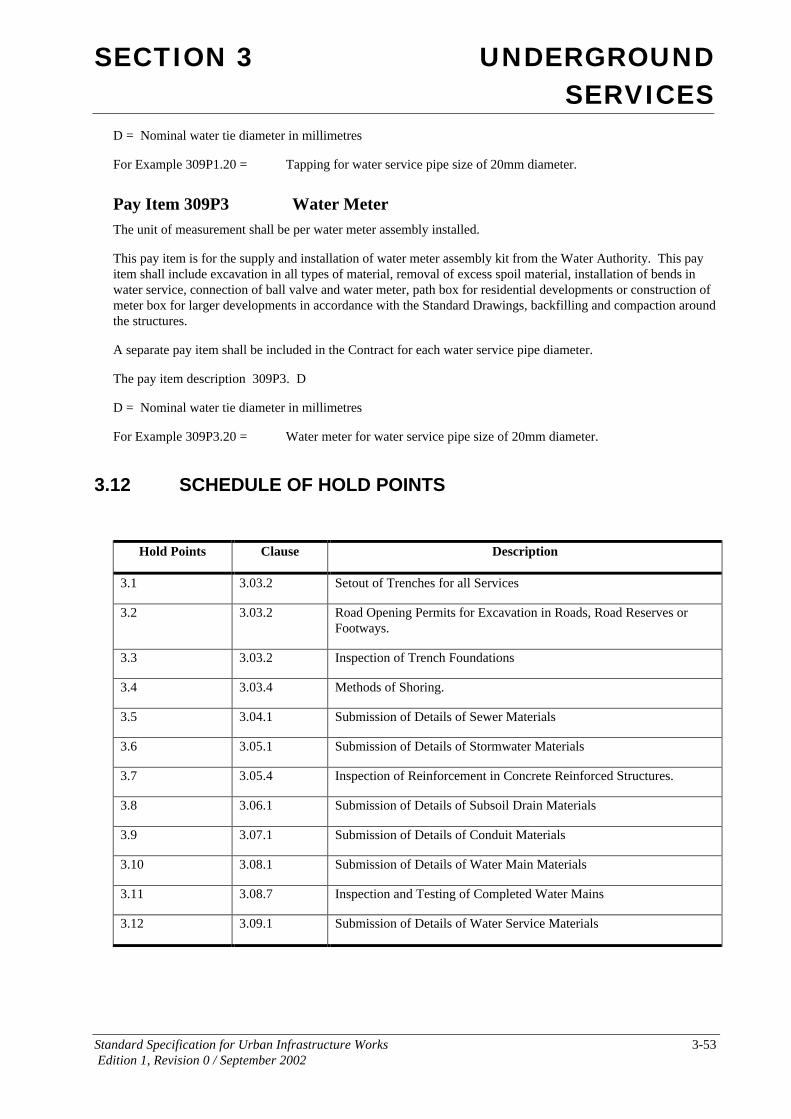
SECTION 3 UNDERGROUND SERVICES
Standard Specification for Urban Infrastructure Works 3-53 Edition 1, Revision 0 / September 2002
D = Nominal water tie diameter in millimetres
For Example 309P1.20 = Tapping for water service pipe size of 20mm diameter.
Pay Item 309P3 Water Meter The unit of measurement shall be per water meter assembly installed.
This pay item is for the supply and installation of water meter assembly kit from the Water Authority. This pay item shall include excavation in all types of material, removal of excess spoil material, installation of bends in water service, connection of ball valve and water meter, path box for residential developments or construction of meter box for larger developments in accordance with the Standard Drawings, backfilling and compaction around the structures.
A separate pay item shall be included in the Contract for each water service pipe diameter.
The pay item description 309P3. D
D = Nominal water tie diameter in millimetres
For Example 309P3.20 = Water meter for water service pipe size of 20mm diameter.
3.12 SCHEDULE OF HOLD POINTS
Hold Points Clause Description
3.1 3.03.2 Setout of Trenches for all Services
3.2 3.03.2 Road Opening Permits for Excavation in Roads, Road Reserves or Footways.
3.3 3.03.2 Inspection of Trench Foundations
3.4 3.03.4 Methods of Shoring.
3.5 3.04.1 Submission of Details of Sewer Materials
3.6 3.05.1 Submission of Details of Stormwater Materials
3.7 3.05.4 Inspection of Reinforcement in Concrete Reinforced Structures.
3.8 3.06.1 Submission of Details of Subsoil Drain Materials
3.9 3.07.1 Submission of Details of Conduit Materials
3.10 3.08.1 Submission of Details of Water Main Materials
3.11 3.08.7 Inspection and Testing of Completed Water Mains
3.12 3.09.1 Submission of Details of Water Service Materials