Embed Size (px)
Citation preview

Section 3:Session 2: Continued Plant Operation
261

A BNFL Group Company
263
Background and Technical Basis:Evaluation of Upper Head Penetration
Flawsin the ASME Code
Warren Bamford, Westinghouse Electricand
Guy DeBoo, Exelon
264
Introduction• A consistent and defendable evaluation process for the
treatment of flaws in head penetrations has been developed
• The original work on these methods and acceptance criteria was done in the early 1990s, and reviewed and approved by NRC, but not codified
• In 2001, it was decided that the acceptance criteria should be expanded and put into the ASME code
• This work was completed in April of 2003, and will appear in the 2004 Edition of Section XI
• NRC endorsed this methodology in a letter to NEI published April 22, 2003
265
• Flaw Characterization• Evaluation Process• Stress Corrosion Crack Growth• Example Results to Verify PWSCC
Model• Fatigue Crack Growth• Flaw Acceptance Criteria• Example Application
266
Flaw Characterization
• The approach already contained in Section XI, in IWA 3400-1 can be used directly.
• Flaws must be resolved into axial and circumferential components
• The location of the flaw relative to the attachment weld must be determined
267
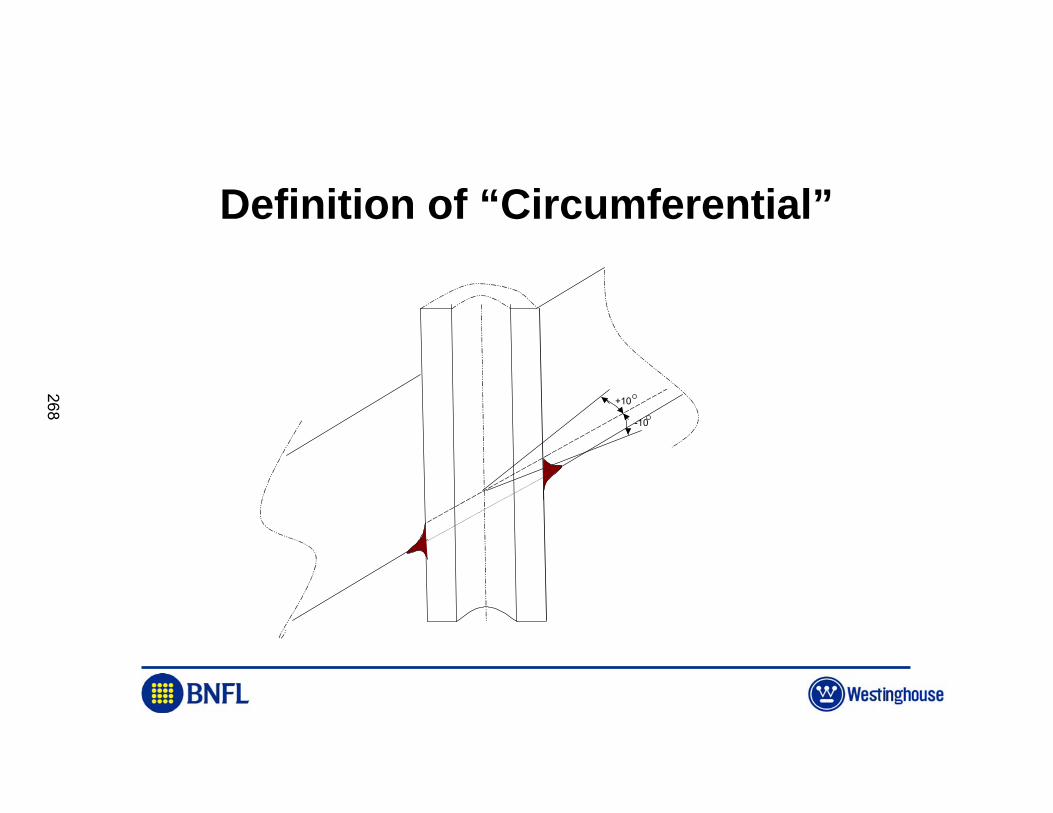
Definition of “Circumferential”
+10
-10
268
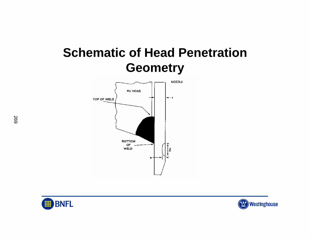
Schematic of Head Penetration Geometry
269
Evaluation Process
• Predict future growth due to – Fatigue– PWSCC
• Compare future growth with acceptance criteria to determine next inspection
• Process is similar to pipe flaw evaluation, already in Section XI, Appendix C
270
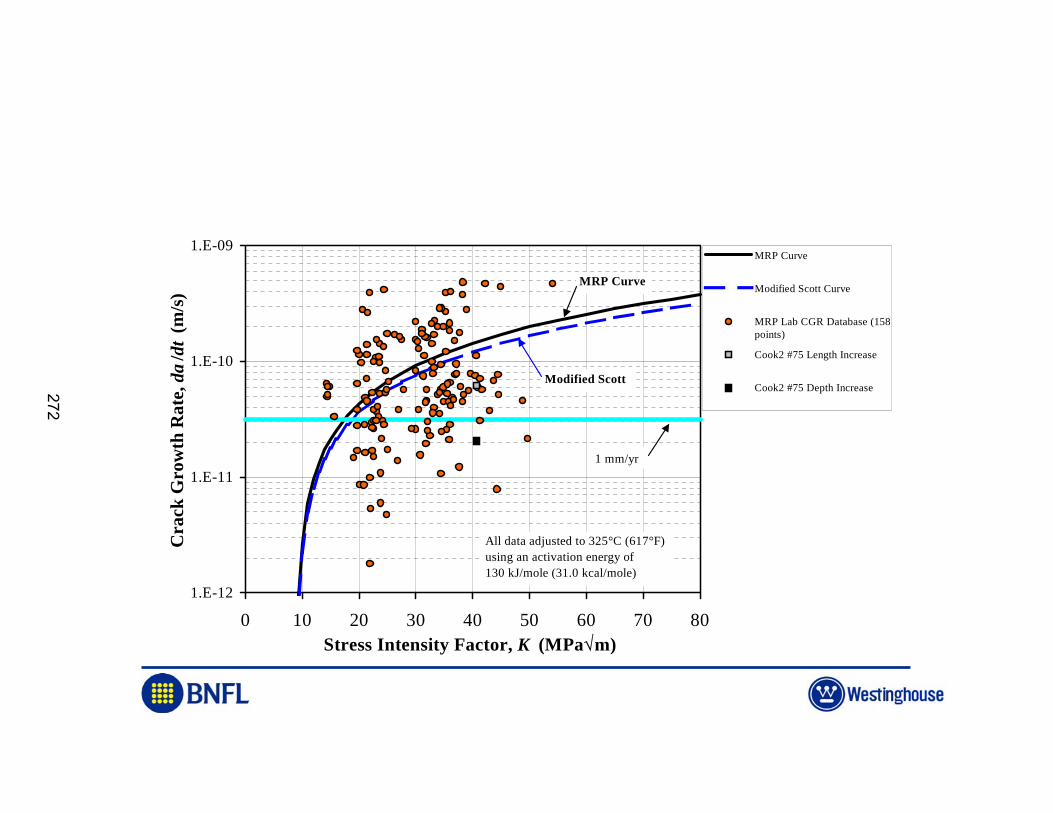
Stress Corrosion Crack Growth
• Use EPRI MRP-55 Rev.A report as basis for growth model: Alloy 600 Base Metal
• Goal is a “Best Estimate” Prediction• Model is higher than the mean, so it is
conservative• Additional conservations added in
acceptance criteria
271
1.E-12
1.E-11
1.E-10
1.E-09
0 10 20 30 40 50 60 70 80Stress Intensity Factor, K (MPa√m)
Cra
ck G
row
th R
ate,
da
/ dt
(m/s
)
MRP Curve
Modified Scott Curve
MRP Lab CGR Database (158points)
Cook2 #75 Length Increase
Cook2 #75 Depth Increase
All data adjusted to 325°C (617°F)using an activation energy of130 kJ/mole (31.0 kcal/mole)
1 mm/yr
MRP Curve
Modified Scott
272
Example Calculation to Verify SCC Growth Rate
• Inspections of D.C. Cook Unit 2 in 1994, 1996.
• Crack sizes determined with ECT, UT• Crack growth was below predictions• Flaw shape did not change
273
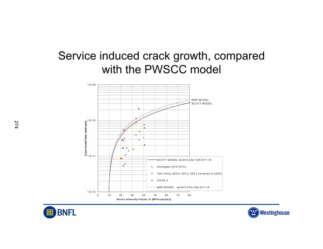
Service induced crack growth, compared with the PWSCC model
1.E-12
1.E-11
1.E-10
1.E-09
0 10 20 30 40 50 60 70 80
Stress Intensity Factor, K (M Pa*sqrt(m ))
Cra
ck G
row
th R
ate,
da/
dt (m
/s)
SC O T T M O DEL da/dt=2.23e-12(K-9)^1.16
H untington (315-331C )
T est T em p.(302.6, 340.2, 353.3 corrected to 325C )
C O O K 2
M RP M O DEL da/d t=2.67e-12(K-9)^1.16
SC O T T M O D ELM R P M O D EL
274
Fatigue Crack Growth
• Model obtained from literature: Argonne Report NUREG/CR-6721
• Several other references reviewed• Contribution to total growth is negligible
275
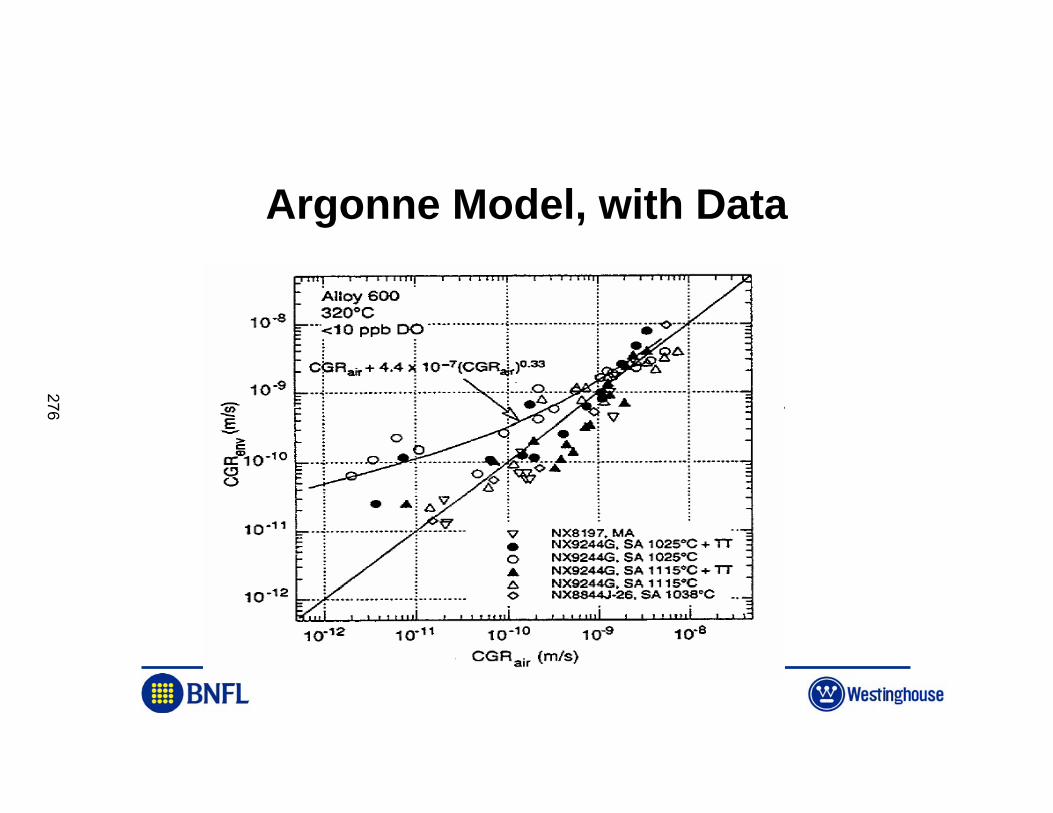
Argonne Model, with Data
276
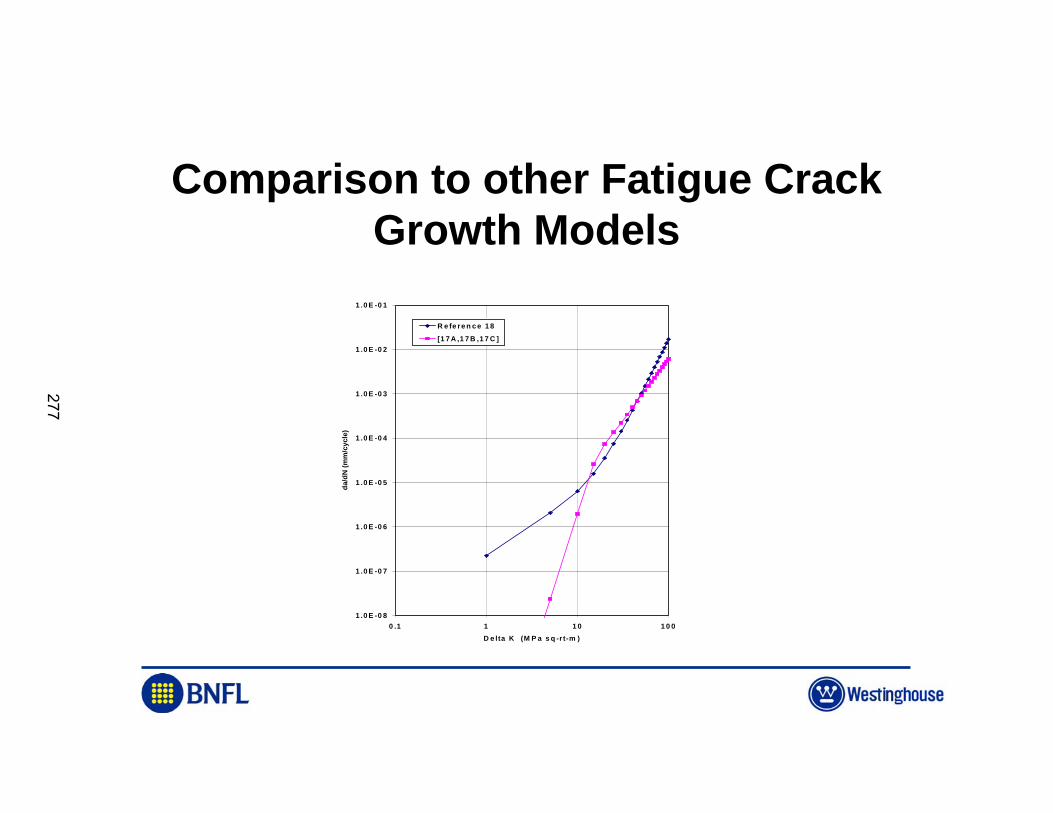
Comparison to other Fatigue Crack Growth Models
1 .0 E -0 8
1 .0 E -0 7
1 .0 E -0 6
1 .0 E -0 5
1 .0 E -0 4
1 .0 E -0 3
1 .0 E -0 2
1 .0 E -0 1
0 .1 1 1 0 1 0 0D e lta K (M P a s q -r t-m )
da/d
N (m
m/c
ycle
)
R e fe re n c e 1 8[1 7 A ,1 7 B ,1 7 C ]
277
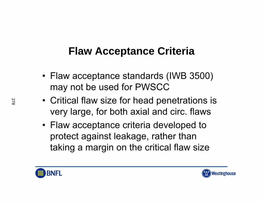
Flaw Acceptance Criteria
• Flaw acceptance standards (IWB 3500) may not be used for PWSCC
• Critical flaw size for head penetrations is very large, for both axial and circ. flaws
• Flaw acceptance criteria developed to protect against leakage, rather than taking a margin on the critical flaw size
278
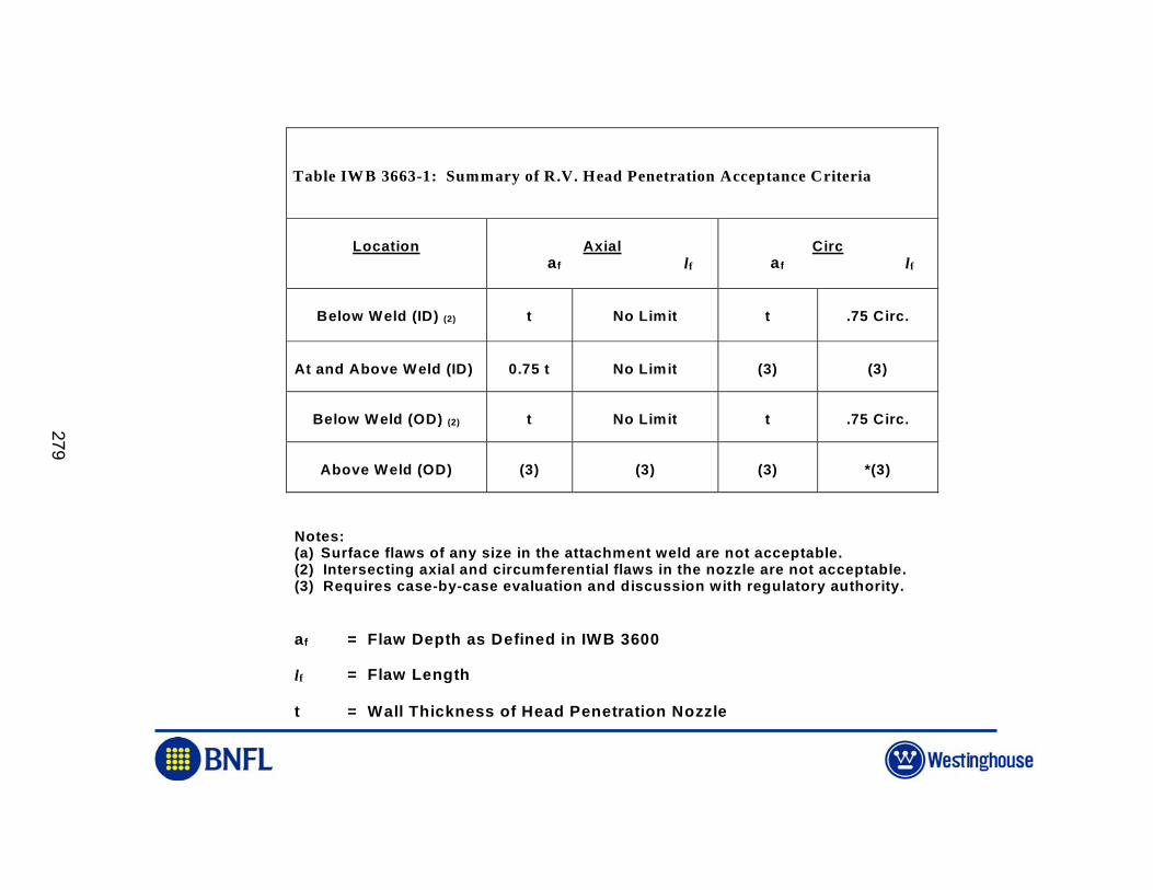
Table IWB 3663-1: Summary of R.V. Head Penetration Acceptance Criteria
Location Axial af lf
Circ af lf
Below Weld (ID) (2) t No Limit t .75 Circ.
At and Above Weld (ID) 0.75 t No Limit (3) (3)
Below Weld (OD) (2) t No Limit t .75 Circ.
Above Weld (OD) (3) (3) (3) *(3)
Notes:(a) Surface flaws of any size in the attachment weld are not acceptable.(2) Intersecting axial and circumferential flaws in the nozzle are not acceptable.(3) Requires case-by-case evaluation and discussion with regulatory authority.
af = Flaw Depth as Defined in IWB 3600
lf = Flaw Length
t = Wall Thickness of Head Penetration Nozzle
279
0.000
0.100
0.200
0.300
0.400
0.500
0.600
0.700
0.800
0.900
1.000
0 1 2 3 4 5
time (year)
a/t (
flaw
dep
th/w
all t
hick
ness
)
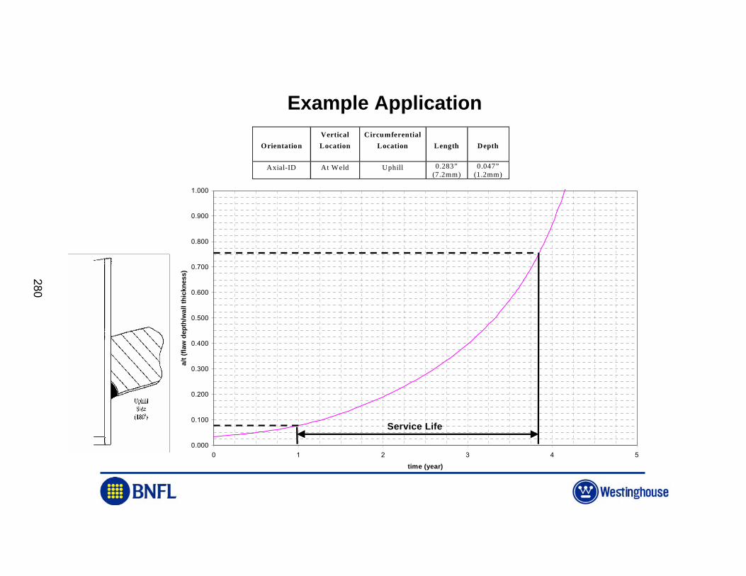
Service Life
OrientationVerticalLocation
CircumferentialLocation Length Depth
Axial-ID At Weld Uphill 0.283”(7.2mm)
0.047”(1.2mm)
Example Application
280
ASME Code Actions
• This action was approved in principle at the Working Group level in December of 2002
• Subcommittee Section XI approved the action in February 2003
• The action will be published soon as an ASME Nuclear Code Case, and in the 2004 Edition of Section XI, as paragraph IWB 3660.
• NRC endorsed this methodology in a letter to NEI published April 22, 2003
281

A BNFL Group Company
282
© EDF : DPN/CAPE, DIN/SEPTEN, RD/MMC – NRC Conference Sept. 29 – Oct. 2, Gaithersburg 1
MAINTENANCE STRATEGY OF INCONEL COMPONENTS IN PWR PRIMARY SYSTEM IN
FRANCE
François CHAMPIGNY (EDF – Nuclear Power Plant Operations )François CHAPELIER (EDF – Nuclear Power Plant Operations – Liaison Engineer with
INPO)Claude AMZALLAG (EDF – Nuclear Engineering)
François VAILLANT (EDF – Research & Development)
283
© EDF : DPN/CAPE, DIN/SEPTEN, RD/MMC – NRC Conference Sept. 29 – Oct. 2, Gaithersburg
MAINTENANCE STRATEGY OF INCONEL COMPONENTS IN PWR PRIMARY SYSTEM IN FRANCE
CONTENT
� INTRODUCTION� NON DESTRUCTIVE EXAMINATIONS, REPAIRS� INVESTIGATION PROGRAM� INSPECTION PROGRAM SINCE 1996� EXPERIENCE FEEDBACK AND VESSEL HEAD REPLACEMENT� OTHER INCONEL COMPONENTS� CONCLUSION
284
© EDF : DPN/CAPE, DIN/SEPTEN, RD/MMC – NRC Conference Sept. 29 – Oct. 2, Gaithersburg
MAINTENANCE STRATEGY OF INCONEL COMPONENTS IN PWR PRIMARY SYSTEM IN FRANCE : Bugey Leak
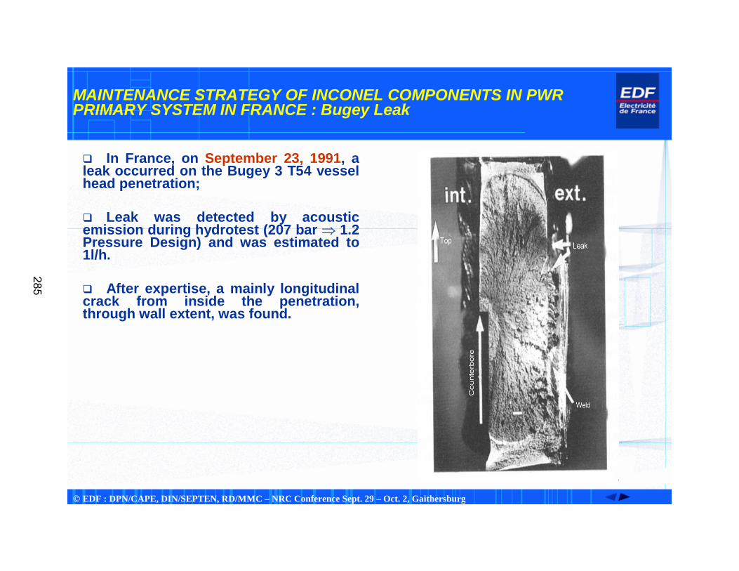
� In France, on September 23, 1991, a leak occurred on the Bugey 3 T54 vessel head penetration;
� Leak was detected by acoustic emission during hydrotest (207 bar � 1.2 Pressure Design) and was estimated to 1l/h.
� After expertise, a mainly longitudinal crack from inside the penetration, through wall extent, was found.
285
© EDF : DPN/CAPE, DIN/SEPTEN, RD/MMC – NRC Conference Sept. 29 – Oct. 2, Gaithersburg
MAINTENANCE STRATEGY OF INCONEL COMPONENTS IN PWR PRIMARY SYSTEM IN FRANCE : Bugey results
� NDE results� First non destructive examinations, penetrant testing, Eddy currents, ultrasonic testing, revealed longitudinal cracks opposite to the weld in the tube part of the penetration.
� Analysis of the crack morphology� Primary water stress corrosion cracking (PWSCC),� No fatigue,� Orientation of the crack : mainly longitudinal� Azimutal location : 0° and 180°; most cracks were located at 180°,� Operating time : ~ 80 000 hours (BUGEY)
286
© EDF : DPN/CAPE, DIN/SEPTEN, RD/MMC – NRC Conference Sept. 29 – Oct. 2, Gaithersburg
MAINTENANCE STRATEGY OF INCONEL COMPONENTS IN PWR PRIMARY SYSTEM IN FRANCE : 1st Investigations
� NON DESTRUCTIVE EXAMINATION� 1st NDE developments :ET
Detection by Eddy current with a classical rotating probe but need to remove thermal sleeve
� 2nd NDE development : ET & UTDetection by Eddy current with « blade probe » without removing thermal sleeveCharacterization by ultrasonic « blade probe » using Time Of Flight Technique (TOFT)Video probe
� Probes tested on mock-ups with artificial, realistic and real flaws.� FIRST NDE RESULTS
� At the end of 1992 :�Five 900 MW vessel heads with cracked penetrations and four 1300 MW (after 30000 to 40000 hours operating).
� At the end of 1994 :�47 VHs had been inspected; �33 VHs out of 47 with tiny indications and very few cracks in penetrations.
� Alternative methods� Leak detection system using N13
installed on about 20 vessel heads with alloy 600 penetrations to prevent new leak.� No leak was detected since 1991,� Systems dismantled when vessel heads are replaced by Inconel 690.
� Visual testing on vessel heads
287
© EDF : DPN/CAPE, DIN/SEPTEN, RD/MMC – NRC Conference Sept. 29 – Oct. 2, Gaithersburg
MAINTENANCE STRATEGY OF INCONEL COMPONENTS IN PWR PRIMARY SYSTEM IN FRANCE : 1st Investigations
REPAIRS� After vessel head penetration Bugey 3 T54 leak :
� Repair solution tested,� Framatome achieved repairs,� Long time (~ 1 year),� High cost (> 1.5 M€).
REPLACEMENT� Due to the homogeneous fleet of vessel heads and RPVs, EDF decided to replace all vessel heads with alloy 600 penetrations at the beginning of 1993. That decision concerned 54 VH out of 58, last four ones were equipped with alloy 690 penetrations.� New vessel heads : base metal with alloy 690, welds with alloy 152.
288
© EDF : DPN/CAPE, DIN/SEPTEN, RD/MMC – NRC Conference Sept. 29 – Oct. 2, Gaithersburg
MAINTENANCE STRATEGY OF INCONEL COMPONENTS IN PWR PRIMARY SYSTEM IN FRANCE : Investigation program
� A large investigation program is launched in 1992
� Operating temperature of the components in relation with thermal-hydraulics,� Susceptibility of the material to PWSCC, depending upon its microstructure and the manufacturing process,� Stress identification (residual and operating) and evaluation by measurements, mock-up corrosion tests and Finite Element Analysis (FEA),� Effect of surface finish on crack initiation,� Crack growth rate.
289
© EDF : DPN/CAPE, DIN/SEPTEN, RD/MMC – NRC Conference Sept. 29 – Oct. 2, Gaithersburg
MAINTENANCE STRATEGY OF INCONEL COMPONENTS IN PWR PRIMARY SYSTEM IN FRANCE : Investigation program
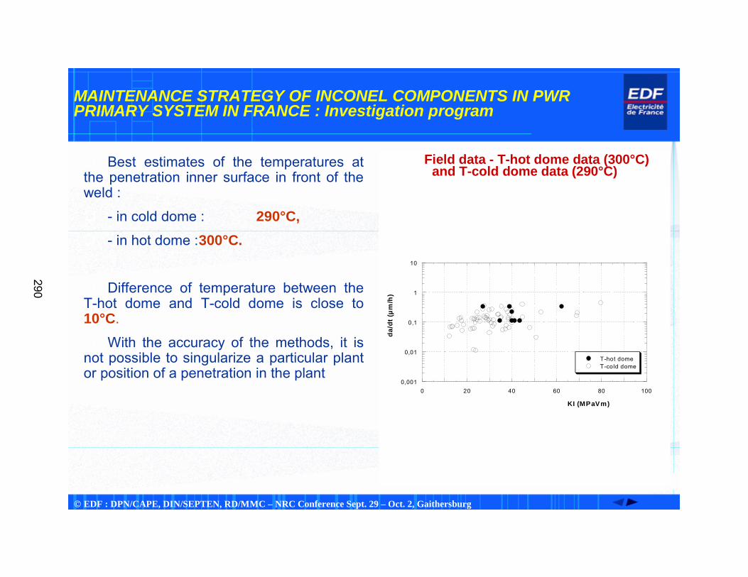
� Best estimates of the temperatures at the penetration inner surface in front of the weld :
� - in cold dome : 290°C,� - in hot dome :300°C.
� Difference of temperature between the T-hot dome and T-cold dome is close to 10°C.
� With the accuracy of the methods, it is not possible to singularize a particular plant or position of a penetration in the plant
� Field data - T-hot dome data (300°C)and T-cold dome data (290°C)
0,001
0,01
0,1
1
10
0 20 40 60 80 100
T-hot domeT-cold dome
da/d
t (µm
/h)
KI (MPaVm)
290
© EDF : DPN/CAPE, DIN/SEPTEN, RD/MMC – NRC Conference Sept. 29 – Oct. 2, Gaithersburg
MAINTENANCE STRATEGY OF INCONEL COMPONENTS IN PWR PRIMARY SYSTEM IN FRANCE : Investigation program
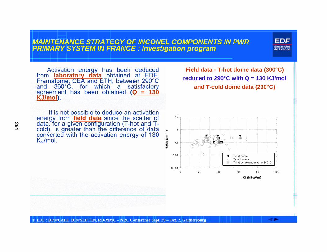
Activation energy has been deduced from laboratory data obtained at EDF, Framatome, CEA and ETH, between 290°C and 360°C, for which a satisfactory agreement has been obtained (Q = 130 KJ/mol).
It is not possible to deduce an activation energy from field data since the scatter of data, for a given configuration (T-hot and T-cold), is greater than the difference of data converted with the activation energy of 130 KJ/mol.
� Field data - T-hot dome data (300°C)� reduced to 290°C with Q = 130 KJ/mol
� and T-cold dome data (290°C)
0,001
0,01
0,1
1
10
0 20 40 60 80 100
T-hot domeT-cold domeT-hot dome (reduced to 290°C)
da/d
t (µm
/h)
KI (MPaVm)
291
© EDF : DPN/CAPE, DIN/SEPTEN, RD/MMC – NRC Conference Sept. 29 – Oct. 2, Gaithersburg
MAINTENANCE STRATEGY OF INCONEL COMPONENTS IN PWR PRIMARY SYSTEM IN FRANCE : Investigation program
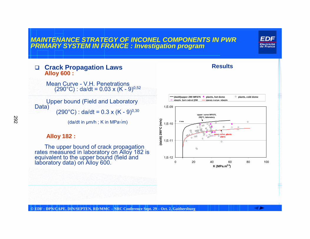
� Crack Propagation LawsAlloy 600 :
Mean Curve - V.H. Penetrations (290°C) : da/dt = 0.03 x (K - 9)0,52
Upper bound (Field and Laboratory Data)
(290°C) : da/dt = 0.3 x (K - 9)0,30
(da/dt in µm/h ; K in MPa√m)
Alloy 182 :
� The upper bound of crack propagation rates measured in laboratory on Alloy 182 is equivalent to the upper bound (field and laboratory data) on Alloy 600.
Results
1,E-12
1,E-11
1,E-10
1,E-09
0 20 40 60 80 100K (MPa.m0.5)
(da/
dt) 2
90°C
(m/s
)
(da/dt)upper 290 WF675 plants, hot dome plants, cold domeplants, hot calcul 290 mean curve, plants
upper curve WF675, 290°C, laboratory
mean curve, plants 290°C
4 mm
292
© EDF : DPN/CAPE, DIN/SEPTEN, RD/MMC – NRC Conference Sept. 29 – Oct. 2, Gaithersburg
MAINTENANCE STRATEGY OF INCONEL COMPONENTS IN PWR PRIMARY SYSTEM IN FRANCE : Investigation program
�Characteristic Values of Crack Growth Rates in Depth
Maximum crack growth rate of one crack : 0,46 µm/h (propagation of 3,5 mm measured over an operating cycle of 7661 hours),
Mean value of maximum crack growth rates observed on overall cracks ofoverallpenetrations : 0,18 µm/h
(propagation of 1,4 mm over a mean operating cycle de 8000 hours).
293
© EDF : DPN/CAPE, DIN/SEPTEN, RD/MMC – NRC Conference Sept. 29 – Oct. 2, Gaithersburg
MAINTENANCE STRATEGY OF INCONEL COMPONENTS IN PWR PRIMARY SYSTEM IN FRANCE : Investigation program
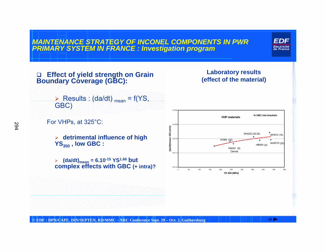
� Effect of yield strength on Grain Boundary Coverage (GBC):
� Results : (da/dt) mean = f(YS, GBC)
For VHPs, at 325°C:
� detrimental influence of high YS350 , low GBC :
� (da/dt)mean = 6.10-15 YS1.66 but complex effects with GBC (+ intra)?
Laboratory results(effect of the material)
1,E-12
1,E-11
1,E-10
1,E-09
1,E-08
0 50 100 150 200 250 300 350 400 450 500
YS 350 (MPa)(d
a/dt
)mea
n 32
5 (m
/s)
91069 (32)
746301 (9)Ciemat
WH220 (20-50)
HB400
WF675
Arb2510
(15)
(25)(22
% GBC into bracketsVHP materials
294
© EDF : DPN/CAPE, DIN/SEPTEN, RD/MMC – NRC Conference Sept. 29 – Oct. 2, Gaithersburg
MAINTENANCE STRATEGY OF INCONEL COMPONENTS IN PWR PRIMARY SYSTEM IN FRANCE : Maintenance strategy
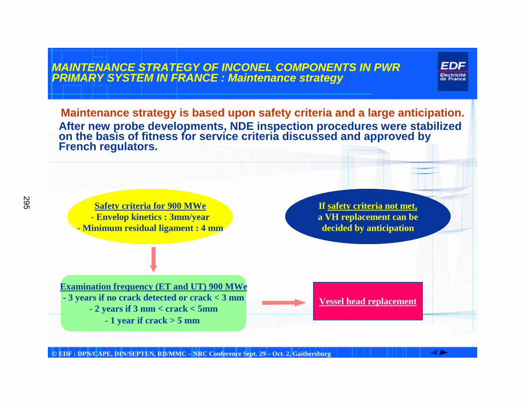
Maintenance strategy is based upon safety criteria and a large anticipation. After new probe developments, NDE inspection procedures were stabilized on the basis of fitness for service criteria discussed and approved by French regulators.
Safety criteria for 900 MWe- Envelop kinetics : 3mm/year
- Minimum residual ligament : 4 mm
Examination frequency (ET and UT) 900 MWe- 3 years if no crack detected or crack < 3 mm
- 2 years if 3 mm < crack < 5mm- 1 year if crack > 5 mm
Vessel head replacement
If safety criteria not met,a VH replacement can bedecided by anticipation
295
© EDF : DPN/CAPE, DIN/SEPTEN, RD/MMC – NRC Conference Sept. 29 – Oct. 2, Gaithersburg
MAINTENANCE STRATEGY OF INCONEL COMPONENTS IN PWR PRIMARY SYSTEM IN FRANCE : NDE results
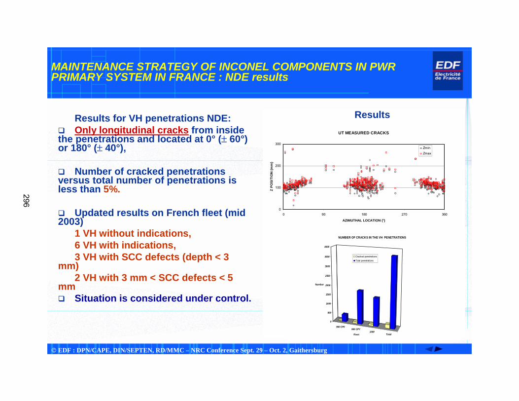
Results for VH penetrations NDE:� Only longitudinal cracks from inside the penetrations and located at 0° (± 60°)or 180° (± 40°),
� Number of cracked penetrations versus total number of penetrations is less than 5%.
� Updated results on French fleet (mid 2003)
1 VH without indications,6 VH with indications,3 VH with SCC defects (depth < 3
mm)2 VH with 3 mm < SCC defects < 5
mm� Situation is considered under control.
ResultsUT MEASURED CRACKS
0
100
200
300
0 90 180 270 360
AZIMUTHAL LOCATION (°)
Z PO
SITI
ON
(mm
)
ZminZmax
900 CP0900 CPY
1300Total
0
500
1000
1500
2000
2500
3000
3500
4000
Number
Fleet
NUMBER OF CRACKS IN THE VH PENETRATIONS
Cracked penetrationsTotal penetrations
296
© EDF : DPN/CAPE, DIN/SEPTEN, RD/MMC – NRC Conference Sept. 29 – Oct. 2, Gaithersburg
MAINTENANCE STRATEGY OF INCONEL COMPONENTS IN PWR PRIMARY SYSTEM IN FRANCE : Overall results
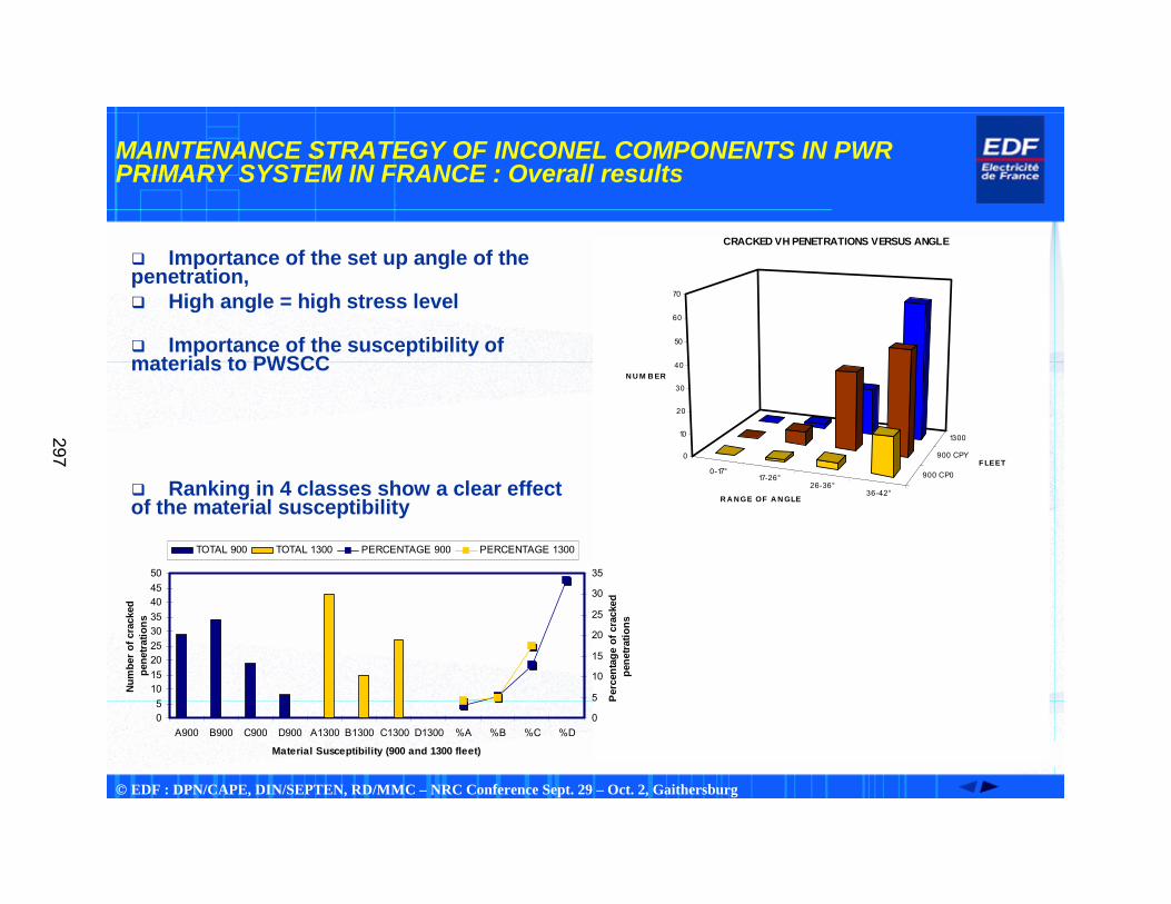
� Importance of the set up angle of the penetration,� High angle = high stress level
� Importance of the susceptibility of materials to PWSCC
� Ranking in 4 classes show a clear effect of the material susceptibility
0-17°17-26°
26-36°36-42°
900 CP0
900 CPY
1300
0
10
20
30
40
50
60
70
N U M B ER
R A NGE OF A N GLE
FLEET
CRACKED VH PENETRATIONS VERSUS ANGLE
05
101520253035404550
A900 B900 C900 D900 A1300 B1300 C1300 D1300 %A %B %C %D
Material Susceptibility (900 and 1300 fleet)
Num
ber o
f cra
cked
pe
netra
tions
0
5
10
15
20
25
30
35
Perc
enta
ge o
f cra
cked
pe
netra
tions
TOTAL 900 TOTAL 1300 PERCENTAGE 900 PERCENTAGE 1300
297
© EDF : DPN/CAPE, DIN/SEPTEN, RD/MMC – NRC Conference Sept. 29 – Oct. 2, Gaithersburg
MAINTENANCE STRATEGY OF INCONEL COMPONENTS IN PWR PRIMARY SYSTEM IN FRANCE : Feedback experience
� Complementary examinations of J groove welds� Dye penetrant testing performed on 754 welds from 11 replaced VH� Results : no defect detected
� Other examinations� In order to prevent any leak with boric acid corrosion on top of vessel head, a video examination of Canopy welds is performed every 10 years.
� VHP with alloy 690� 3 VHP examined by ET technique with same kind of procedure than alloy 600 VHP;� Results : no SCC defects detected and characterized as expected from alloy 690 SG tubes follow up (performed since 1990).
298
© EDF : DPN/CAPE, DIN/SEPTEN, RD/MMC – NRC Conference Sept. 29 – Oct. 2, Gaithersburg
MAINTENANCE STRATEGY OF INCONEL COMPONENTS IN PWR PRIMARY SYSTEM IN FRANCE : Overall results
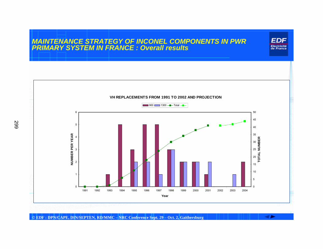
VH REPLACEMENTS FROM 1991 TO 2002 AND PROJECTION
0
1
2
3
4
5
6
1991 1992 1993 1994 1995 1996 1997 1998 1999 2000 2001 2002 2003 2004
Year
NU
MB
ER P
ER Y
EAR
0
5
10
15
20
25
30
35
40
45
50
TOTA
L N
UM
BER
900 1300 Total
299
© EDF : DPN/CAPE, DIN/SEPTEN, RD/MMC – NRC Conference Sept. 29 – Oct. 2, Gaithersburg
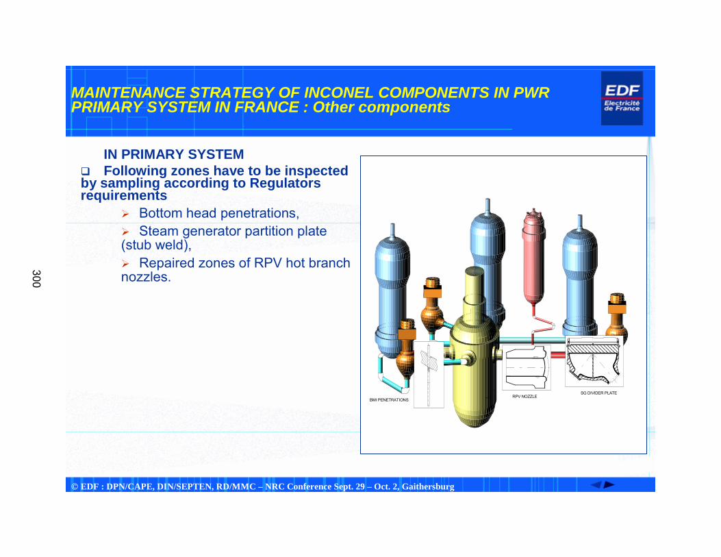
MAINTENANCE STRATEGY OF INCONEL COMPONENTS IN PWR PRIMARY SYSTEM IN FRANCE : Other components
IN PRIMARY SYSTEM� Following zones have to be inspected by sampling according to Regulators requirements
� Bottom head penetrations,� Steam generator partition plate (stub weld),� Repaired zones of RPV hot branch nozzles.
BMI PENETRATIONSRPV NOZZLE
SG DIVIDER PLATE
C2/E
Virole C2
300
© EDF : DPN/CAPE, DIN/SEPTEN, RD/MMC – NRC Conference Sept. 29 – Oct. 2, Gaithersburg
MAINTENANCE STRATEGY OF INCONEL COMPONENTS IN PWR PRIMARY SYSTEM IN FRANCE : Overall results
� NDE results at mid-2003:� From 1992 to mid 2003 : 48 NDE examinations of divider plates (hot branch or cold branch) by dye penetrant method,� From 1992 to mid-2003 : RPV bottom head penetrations of 15 plants by eddy current and ultrasonic methods,� From 1994 to 1996 : 17 reactor vessel nozzles, in hot branch, that contain repairs with alloy 182 (eddy current method),� From 1994 to 1999 : 754 welds of vessel head penetrations from 11 removed vessel heads (dye penetrant method).
have been inspected
No crack indication has been found in these components.
� Flaws have been found:� In steam generator tubes, � Pressurizer instrumentation nozzles in 1989 but were replaced within 2 years, � Vessel head penetrations,� Impacted area of the divider plate of a steam generator.
301
© EDF : DPN/CAPE, DIN/SEPTEN, RD/MMC – NRC Conference Sept. 29 – Oct. 2, Gaithersburg
MAINTENANCE STRATEGY OF INCONEL COMPONENTS IN PWR PRIMARY SYSTEM IN FRANCE : Other components
� Since 2001, a new program has been established following French regulator’s decision :
� 26 SG partition plates (precursors) + 9 random to be inspected up to 2008,� 12 RPV bottom head penetrations to be inspected up to 2008,� RPV hot branch nozzles repaired zones (stress relieved during manufacturing) to be inspected with a qualified procedure at the third ten years visit (beginning 2009).
� Examination results :� 2 random SG and 1 precursor without SCC defects,� 2 new inspections of RPV BMI’s but no SCC defects,� 4 Inconel repaired zones in RPV nozzles but no defects declared.
302
© EDF : DPN/CAPE, DIN/SEPTEN, RD/MMC – NRC Conference Sept. 29 – Oct. 2, Gaithersburg
MAINTENANCE STRATEGY OF INCONEL COMPONENTS IN PWR PRIMARY SYSTEM IN FRANCE : Back to history
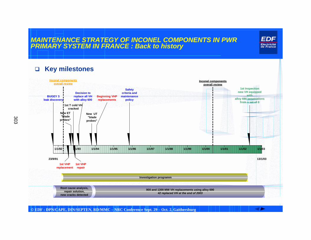
� Key milestones
1/1/92
23/9/91 13/1/03
1/1/93 1/1/94 1/1/95 1/1/96 1/1/97 1/1/98 1/1/99 1/1/00 1/1/01 1/1/02 1/1/03
BUGEY 3leak discovery
Decision toreplace all VHwith alloy 600
1st T cold VHcracked
900 and 1300 MW VH replacements using alloy 69042 replaced VH at the end of 2003
Beginning VHPreplacements
1st Inspectionnew VH equipped
withalloy 690 penetrations
from a set of 3
New ET"blade
probes"
Safetycriteria and
maintenancepolicy
New UT "bladeprobes"
1st VHPreplacement
1st VHPrepair
Root cause analysis,repair solution,
new cracks detected
Inconel componentsoverall review
Investigation programm
Inconel componentsoverall review
303
© EDF : DPN/CAPE, DIN/SEPTEN, RD/MMC – NRC Conference Sept. 29 – Oct. 2, Gaithersburg
MAINTENANCE STRATEGY OF INCONEL COMPONENTS IN PWR PRIMARY SYSTEM IN FRANCE : Summary and conclusions
� In France, alloy 600 VH penetrations PWSCC is better known, since 1991.
� International cooperative laboratory studies benefit for a better control of the phenomenon, (lots of parameters studied), � EDF has anticipated potential degradations by a large NDE program.
� In practice :� Importance given to stress level and susceptibility of materials to PWSCC,� For VHP, inspection criteria based upon safety considerations,� Vessel head replacement policy since 1995 is fruitful :
no new leak, no circumferential cracks detected, no surface breaking defects from J weld.
� Before 2001 and from 1992, a NDE program had been established inorder to inspect BMIs, SG partition plates, repaired zones in RPV nozzles. No SCC defects have been discovered.
304
© EDF : DPN/CAPE, DIN/SEPTEN, RD/MMC – NRC Conference Sept. 29 – Oct. 2, Gaithersburg
MAINTENANCE STRATEGY OF INCONEL COMPONENTS IN PWR PRIMARY SYSTEM IN FRANCE : Summary and conclusions (contd)
� Since 2001, a new NDE program : NDE performed on SG partition plates, bottom head penetrations, repaired zones in RPV nozzles in accordance to French regulator’s decision. Up to now, NDE results are blank (no SCC defects).� 1st inspections on alloy 690 VHP’s are blank (no SCC defects).
In conclusion, EDF has been proactive and has anticipated lots of studies.
but EDF remains very careful to any new event on such material as it was
shown in a recent past (dissimilar welds at VC Summer and Ringhals, VHPscracking at Oconee, Davis-Besse, North Anna, and also BMIs at South Texas Project 1 and at Tsuruga on pressurizer…).
305

Strategic Planning for RPV Head Operation
Vessel Head Penetration Inspection,Cracking and Repair Conference
September 29 – October 2, 2003Gaithersburg, MD
By:Steve Hunt, Dominion Engineering, Inc.
Glenn White, Dominion Engineering, Inc.Dominion Engineering, Inc.
11730 Plaza America Dr.
Reston, VA 20190
307
Strategic Planning for RPV Head Operation 2
Contents
� Objective
� Background
� Inputs/Constraints
� Alternative Management Approaches
� Economic Evaluations
� Conclusions
308
Strategic Planning for RPV Head Operation 3
Objective
� To review strategic planning alternatives for an example moderate susceptibility plant (8-12 EDY) which will
• Ensure a low risk of leakage• Ensure an extremely low risk of core damage• Result in lowest net present value life cycle cost309
Strategic Planning for RPV Head Operation 4
BackgroundPotential Economic Consequences
� The economic consequences of managing RPV head PWSCC can be significant
• EdF is replacing all vessel heads• Cracks and leaks in nozzles in several domestic plants have resulted in
significant outage delays and costs• Boric acid wastage resulting from a PWSCC leak at Davis-Besse has led to
over a 19 month outage• Cracks in large numbers of welds at North Anna 2 led to about a four
month outage while the head was replaced• Industry findings and NRC guidelines/requirements have led to many
expensive inspections• 29 plants in the US have announced plans to replace heads as of September
2003
310
Strategic Planning for RPV Head Operation 5
Inputs/ConstraintsOverview
� The optimum strategic plan should be established considering several constraints• Current condition of head as established by non-destructive examination of all
nozzles (must be free of cracking to remain in moderate category)• Predicted future PWSCC based on industry experience • Inspection intervals to ensure low risk of leakage and very low risk of core
damage• Planned outage durations including provisions for longer outages for SG
replacement, 10 year ISI, etc.• Time and cost required for nozzle inspections and repairs• Time and cost required for replacement head procurement and installation• Potential remedial measures, including an assessment of their cost and
effectiveness
311
Strategic Planning for RPV Head Operation 6
Inputs/ConstraintsInspection Interval Requirements
� For plants in the Moderate category (greater than 8 EDY and less than 12 EDY) the NRC interim order requires that
• Nondestructive examinations shall be performed at least every other refueling outage, and
• Either a bare metal visual inspection or nondestructive examination shall be performed every refueling outage
� Risk-informed modeling work described in previous paper by White (DEI) has demonstrated that these requirements result in
• A low risk of leakage• A very low risk of core damage as measured by Regulatory Guide 1.174
requirements
312
Strategic Planning for RPV Head Operation 7
Inputs/ConstraintsOutage Duration and Inspection/Repair Window
� A realistic assessment must be made of time available during outages for inspections, repairs, remedial measures and head replacement
• Plants with short refueling outages will have less time available for inspections and repairs than plants with longer refueling outages
• Long scheduled outages such as for steam generator replacement or 10 year ISI may provide an ideal opportunity for remedial measures or head replacement
313
Strategic Planning for RPV Head Operation 8
Alternative Management ApproachesOverview
� Continue to inspect and repair as necessary at intervals necessary to ensure low risk of leakage and very low risk of core damage
� Perform remedial measures to reduce risk or possibly increase inspection intervals
� Replace head at the second outage after discovery of first PWSCC
� Replace the vessel head as quickly as possible and perform NDE every 4th outage
314
Strategic Planning for RPV Head Operation 9
Alternative Management ApproachesInspection and Repair Options
� Inspection options are currently available • Volumetric NDE of nozzle plus evaluation for leakage through annulus• Wetted surface examination of nozzle and welds
� Repair options are currently available• Embedded flaw repair• New nozzle structural weld
315
Strategic Planning for RPV Head Operation 10
Alternative Management ApproachesRemedial Measures Options
� Several remedial measures have been proposed including• Modification of internals flange to increase bypass flow and thereby
reduce the head temperature • Surface treatment of nozzle and weld surfaces (shot peening or water jet
conditioning)• Nickel plating• Alloy 152 weld overlays• Roll expansion plus surface conditioning• Application of new structural weld• Mechanical stress improvement• Zinc injection
316
Strategic Planning for RPV Head Operation 11
Alternative Management ApproachesRemedial Measures Effectiveness
� EPRI sponsored tests of several remedial measures• Results presented at 2002 Fontevraud conference
� Most Effective• Water jet conditioning • Electro mechanical nickel brush plating• Shot peening
� Intermediate Effectiveness• Electroless nickel plating• GTAW weld repair• Laser weld repair
� Least Effective• EDM skim cutting• Laser cladding• Flapper wheel surface polishing
317
Strategic Planning for RPV Head Operation 12
Alternative Management ApproachesRemedial Measures Conclusions
� Modification of the internals to reduce temperature is the main remedial measure applied domestically
• Lower head temperature should reduce the rates of crack initiation and growth• Experience in France suggests that the full predicted benefit of lower head
temperature may not be achieved
� While remedial measures may reduce the rate of PWSCC initiation and growth, and thereby reduce the cost of future repairs, it may be difficult to take credit for the improvement in increased inspection intervals
318
Strategic Planning for RPV Head Operation 13
Alternative Management ApproachesHead Replacement
� Installation of a new head is a clear success path
� New heads will be more resistant to PWSCC• Alloy 690 nozzles• Alloy 52 J-welds
� Cost and replacement time is a function of containment building access
• Will head fit through the equipment hatch• Will head fit through equipment hatch with CRDM drives preinstalled
319
Strategic Planning for RPV Head Operation 14
Alternative Management ApproachesHead Replacement - Service Structure Option
� Many domestic PWR plants have original-design head service structures that require significant time for disassembly and reassembly
• Head insulation• Head cooling ducts• CRDM cables • Head cooling fans• Missile shields
� Head disassembly and reassembly time can impact critical path
� Head replacement provides an opportunity to incorporate an integrated head service structure
320
Strategic Planning for RPV Head Operation 15
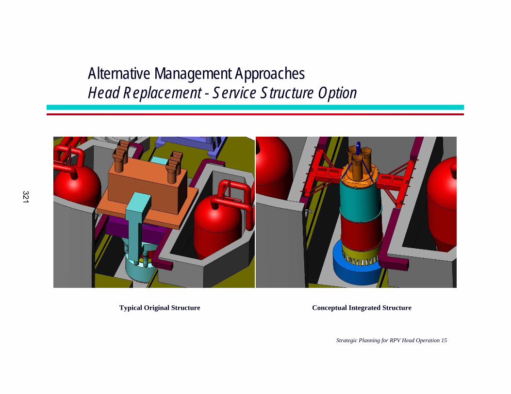
Alternative Management ApproachesHead Replacement - Service Structure Option
Typical Original Structure Conceptual Integrated Structure
321
Strategic Planning for RPV Head Operation 16
Alternative Management ApproachesHead Replacement - Service Structure Option
� An integrated head service structure can be developed for most plants
� Due to other constraints it may not be possible to demonstrate critical path savings for a normal outage
� Secondary benefits of an integrated head service structure may include:
• Free up labor and crane time inside containment during normal outages• Cut several days off of the time to perform a rapid head
disassembly/reassembly for leaking o-ring seal, slow rod drop, etc.• Reduce risk of personnel injury
322
Strategic Planning for RPV Head Operation 17
Economic EvaluationsNPV Analysis Approach
� Establish risk of future cracks/leaks for each alternative considered
� Establish consequences of leakage
� Estimate costs for each alternative
� Calculate Net Present Value (NPV) cost for each alternative assuming
• Planned operating life, including life extension• Discount rate• Estimated value of lost production $/MWe
323
Strategic Planning for RPV Head Operation 18
Economic EvaluationsNPV Analysis Software
� Probabilistic economic analyses can be performed using Monte Carlo methods
• Results provide the range and probability of costs
� In most cases, decisions can be made using a simpler deterministic “best estimate” approach
• One possibility is the LcmVALUE software prepared for EPRI Life Cycle Management Demonstration Project
324
Strategic Planning for RPV Head Operation 19
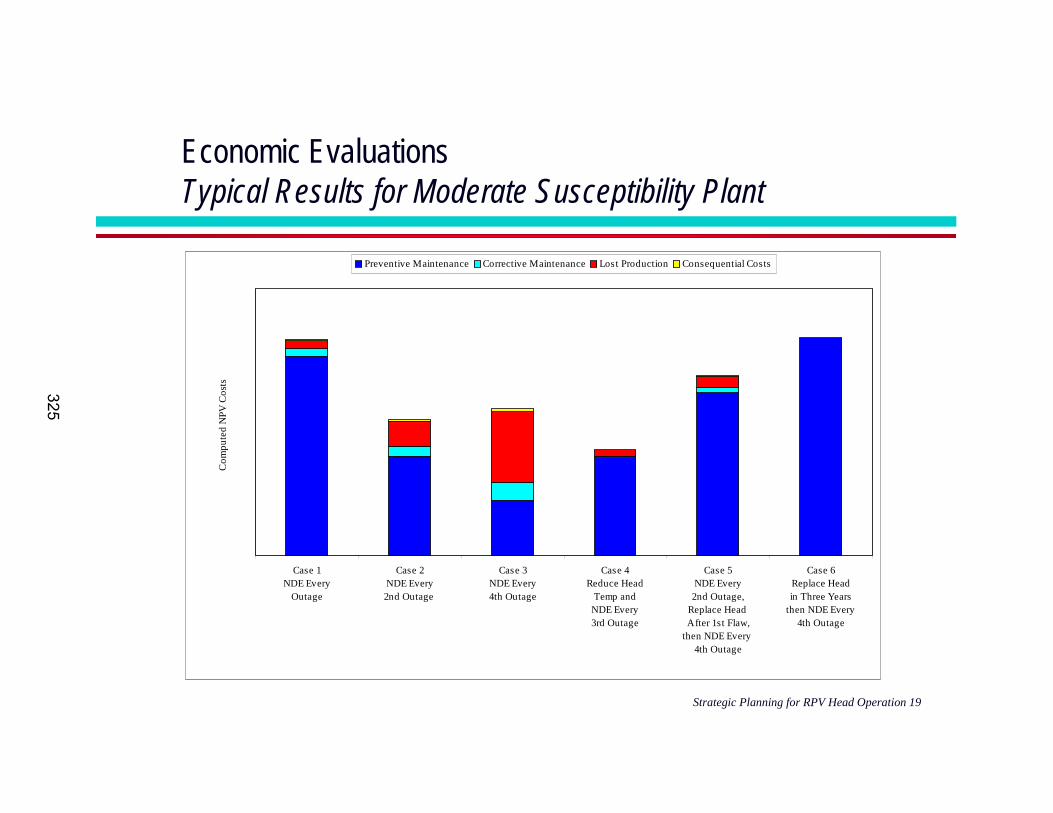
Economic EvaluationsTypical Results for Moderate Susceptibility Plant
0K
5,000K
10,000K
15,000K
20,000K
25,000K
30,000K
Case 1NDE Every
Outage
Case 2NDE Every2nd Outage
Case 3NDE Every4th Outage
Case 4Reduce Head
Temp andNDE Every3rd Outage
Case 5NDE Every
2nd Outage,Replace Head After 1st Flaw,
then NDE Every 4th Outage
Case 6Replace Headin Three Years
then NDE Every4th Outage
Com
pute
d N
PV C
osts
Preventive Maintenance Corrective Maintenance Lost Production Consequential Costs
325
Strategic Planning for RPV Head Operation 20
Conclusions
� For the case study presented, bare metal visual inspection every outage with volumetric examination every second refueling outage appears to be a reasonable approach
• As future inspection data become available and predictive models are refined, there may be a technical basis for retaining inspections every second outage when the plant enters the high susceptibility category based on EDY’s
• Volumetric examination every outage and immediate head replacement appear significantly more expensive
• Remedial measures such as reducing head temperature or waterjet conditioning may be attractive provided inspection intervals can be increased as a result of the effort
• A reasonable longer term plan is to replace the vessel head the second outage after identifying PWSCC
� These results are plant specific and other plants may have different constraints that would affect the optimum solution
326
Reactor Vessel Bottom-Mounted Instrumentation (BMI) Nozzle Repair Development and Implementation at
South Texas Project
D. Waskey
327
2 > CRR 03-90
RV Incore Nozzle FANP European History/ Experience/ Future
> History� In 1991, EDF initiated a programmatic campaign to examine all
I-600 sensitive areas including the in-core nozzles. > Experience (to Date)
� Surveillance of 18 EDF RPV (> 500 penetrations) since 1992, by Framatome.
� To date, no indications of cracks have been found.� On-vessel time for complete inspection ~ one week� 8 more EDF inspections planned through 2009� ECT and UT utilized� Circ and Axial probes being further developed (0°& 45° for
characterization)� Nozzle Material and Weld fusion line inspected – not welds
> Future: � EDF plans to continue examinations of one or two plants per
year through 2009.
328
3 > CRR 03-90
RV Incore Nozzle FANP Domestic History / Experience / Future
> History� During Hot Functional Testing of Oconee-1,iBMI nozzles broke.� Most B&W plants were field modified with thicker Alloy 600 nozzles and 182 filler material
(Davis-Besse modified in shop).> Experience (to Date)
� Davis-Besse performed a bare head visual and found residue on lower RV Head.� PSC written by Framatome employee due to inconclusive evidence from Davis-Besse
residue samples.� Oconee-2 & 3 performed visual inspection outside of insulation – no signs of boron.� ANO-1 performed visual inspection outside of insulation – dispositioned boron traces from
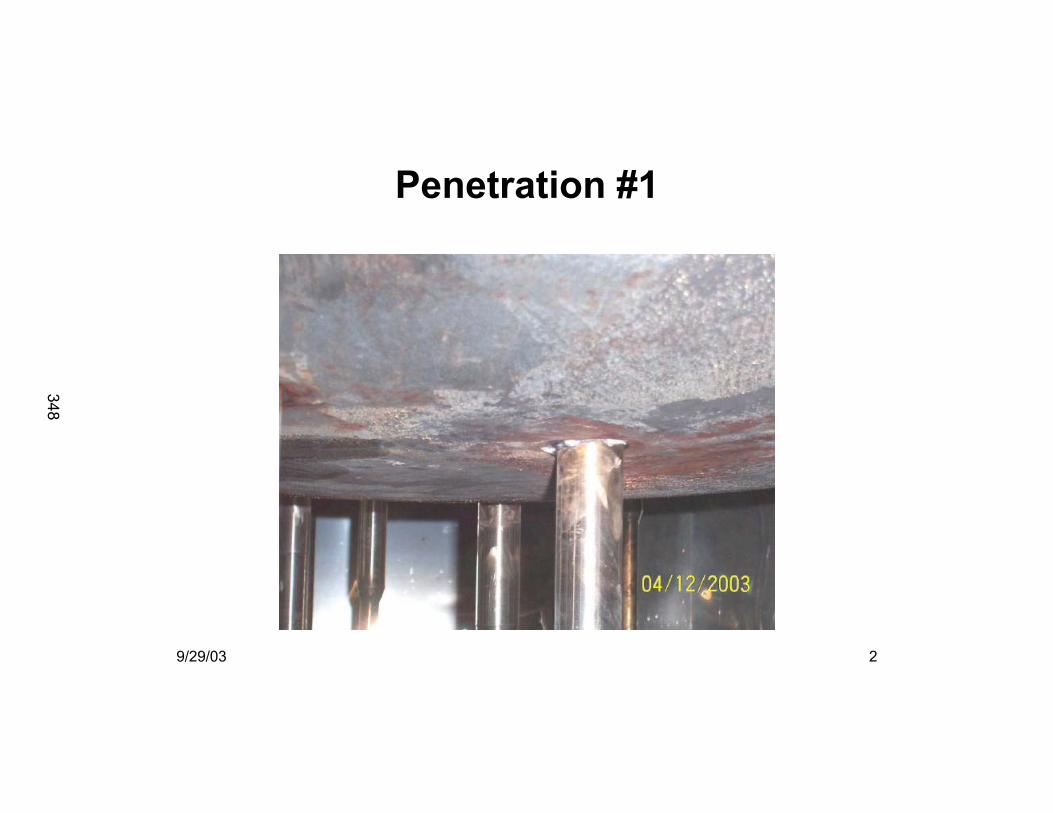
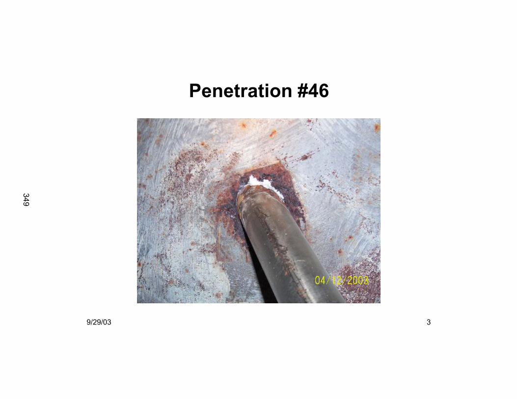
other sources.� STP-1 performed bare head visual inspection and identified two leaking BMI nozzles.
• FANP performed top down VT and UT on 100% of BMI nozzles. Eight BMI J-groove nozzles ET examined from top down.
� FANP repaired two leaking BMI nozzles at STP-1 in June 2003.� Oconee-1 performed bare metal inspections in September 2003.
> Future � Davis-Besse will perform a bare metal after holding full temperature & pressure for one
week.� CR-3 & TMI-1 will perform inspections outside insulation in 2003.� Many Inquiries from industry on inspection and repair services.� MRP recommended bare metal visual to Industry. � NRC Bulletin 2003-02 released August 21, 2003.
• Perform Bare Metal Visual (BMV) on BMI/IMI nozzles at next refueling outage. If unable to perform BMV, describe actions planned to enable BMV during subsequent refueling outage.
329
4 > CRR 03-90
Nozzle Repair Experience
> Over 500 small nozzle repairs performed since 1988 including repairs in last two years at the following units:� St. Lucie 1 – Hot Leg Instrument Nozzles� Oconee 2 – HPI Nozzle� St. Lucie 2 – RCS RTD Nozzles� Davis Besse – RCS RTD Nozzles and HPI Thermal
Sleeve� South Texas 1 – 2 BMI Nozzles� Ringhals 4 – PZR Instrument Nozzle
330
5 > CRR 03-905
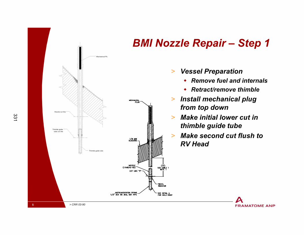
BMI Nozzle Repair – Step 1
> Vessel Preparation� Remove fuel and internals� Retract/remove thimble
> Install mechanical plug from top down
> Make initial lower cut in thimble guide tube
> Make second cut flush to RV Head
Mechanical Plu
Nozzle cut line
Thimble guidetube cut line
Thimble guide tube
331
6 > CRR 03-90
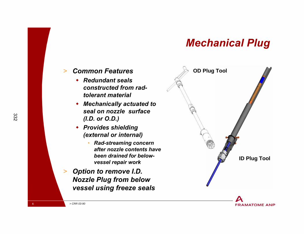
Mechanical Plug
> Common Features� Redundant seals
constructed from rad-tolerant material
� Mechanically actuated to seal on nozzle surface (I.D. or O.D.)
� Provides shielding (external or internal)
• Rad-streaming concern after nozzle contents have been drained for below-vessel repair work
> Option to remove I.D. Nozzle Plug from below vessel using freeze seals
OD Plug Tool
ID Plug Tool
332
7 > CRR 03-90
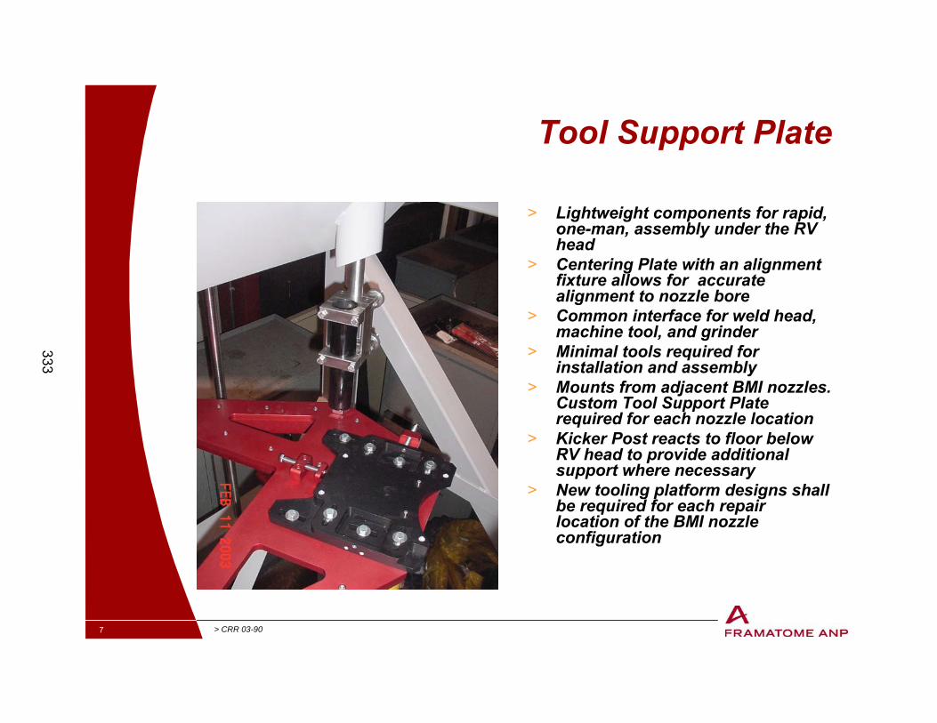
Tool Support Plate
> Lightweight components for rapid, one-man, assembly under the RV head
> Centering Plate with an alignment fixture allows for accurate alignment to nozzle bore
> Common interface for weld head, machine tool, and grinder
> Minimal tools required for installation and assembly
> Mounts from adjacent BMI nozzles. Custom Tool Support Plate required for each nozzle location
> Kicker Post reacts to floor below RV head to provide additional support where necessary
> New tooling platform designs shall be required for each repair location of the BMI nozzle configuration
333
8 > CRR 03-90
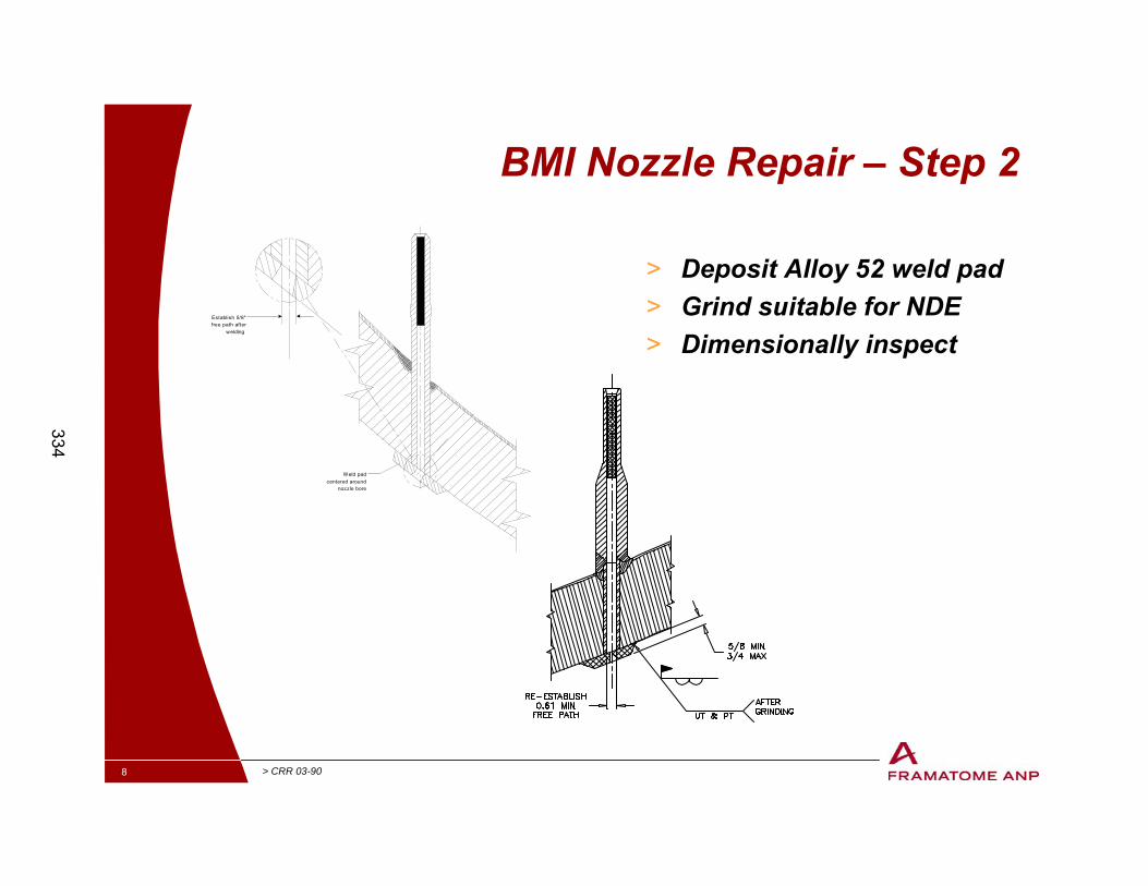
BMI Nozzle Repair – Step 2
> Deposit Alloy 52 weld pad> Grind suitable for NDE> Dimensionally inspect
Establish 5/8"free path after
welding
Weld padcentered around
nozzle bore
S
334
9 > CRR 03-90
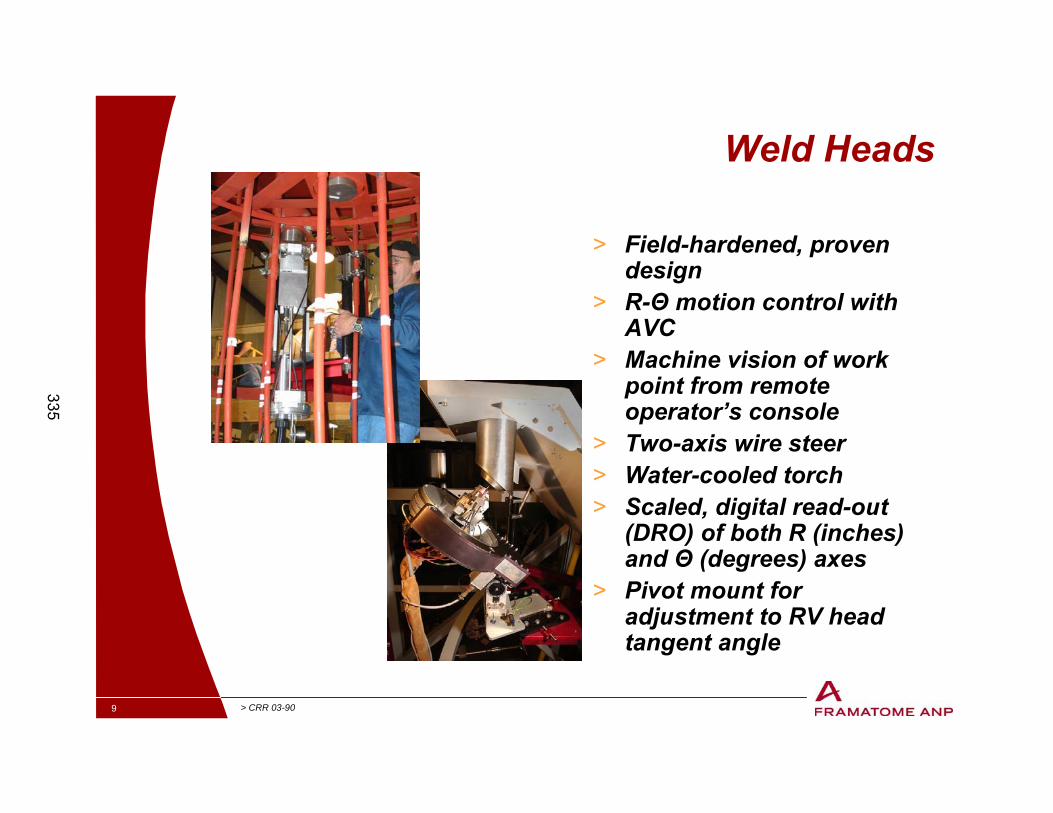
Weld Heads
> Field-hardened, proven design
> R-Θ motion control with AVC
> Machine vision of work point from remote operator’s console
> Two-axis wire steer> Water-cooled torch> Scaled, digital read-out
(DRO) of both R (inches) and Θ (degrees) axes
> Pivot mount for adjustment to RV head tangent angle
335
10 > CRR 03-90
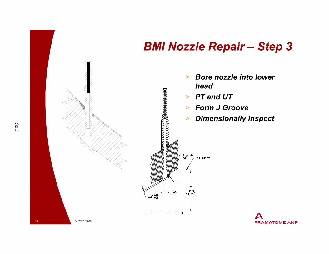
BMI Nozzle Repair – Step 3
> Bore nozzle into lower head
> PT and UT> Form J Groove> Dimensionally inspect336
11 > CRR 03-90
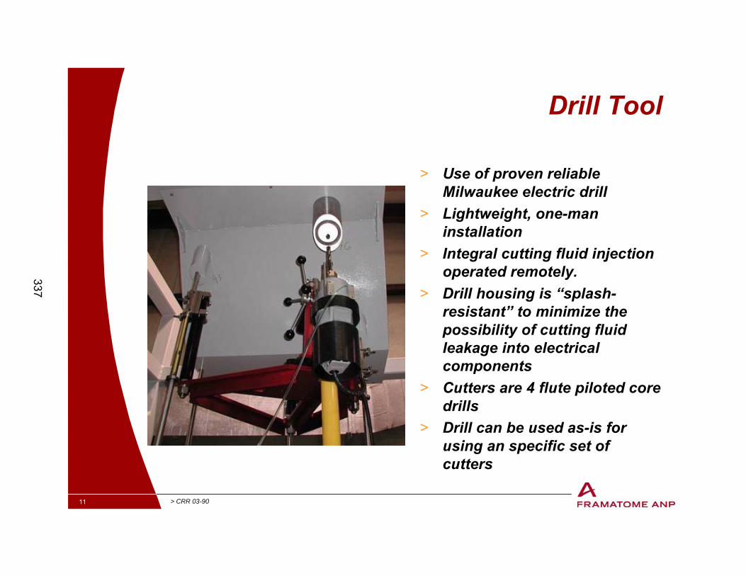
Drill Tool
> Use of proven reliable Milwaukee electric drill
> Lightweight, one-man installation
> Integral cutting fluid injection operated remotely.
> Drill housing is “splash-resistant” to minimize the possibility of cutting fluid leakage into electrical components
> Cutters are 4 flute piloted core drills
> Drill can be used as-is for using an specific set of cutters
337
12 > CRR 03-90
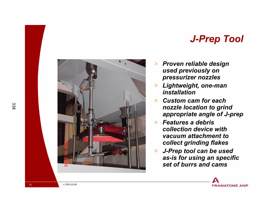
J-Prep Tool
> Proven reliable design used previously on pressurizer nozzles
> Lightweight, one-man installation
> Custom cam for each nozzle location to grind appropriate angle of J-prep
> Features a debris collection device with vacuum attachment to collect grinding flakes
> J-Prep tool can be used as-is for using an specific set of burrs and cams
338
13 > CRR 03-90
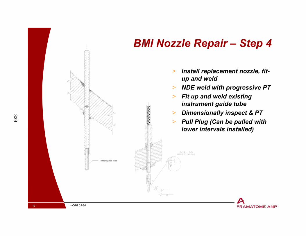
BMI Nozzle Repair – Step 4
> Install replacement nozzle, fit-up and weld
> NDE weld with progressive PT> Fit up and weld existing
instrument guide tube> Dimensionally inspect & PT> Pull Plug (Can be pulled with
lower intervals installed)
Thimble guide tube
339
14 > CRR 03-90
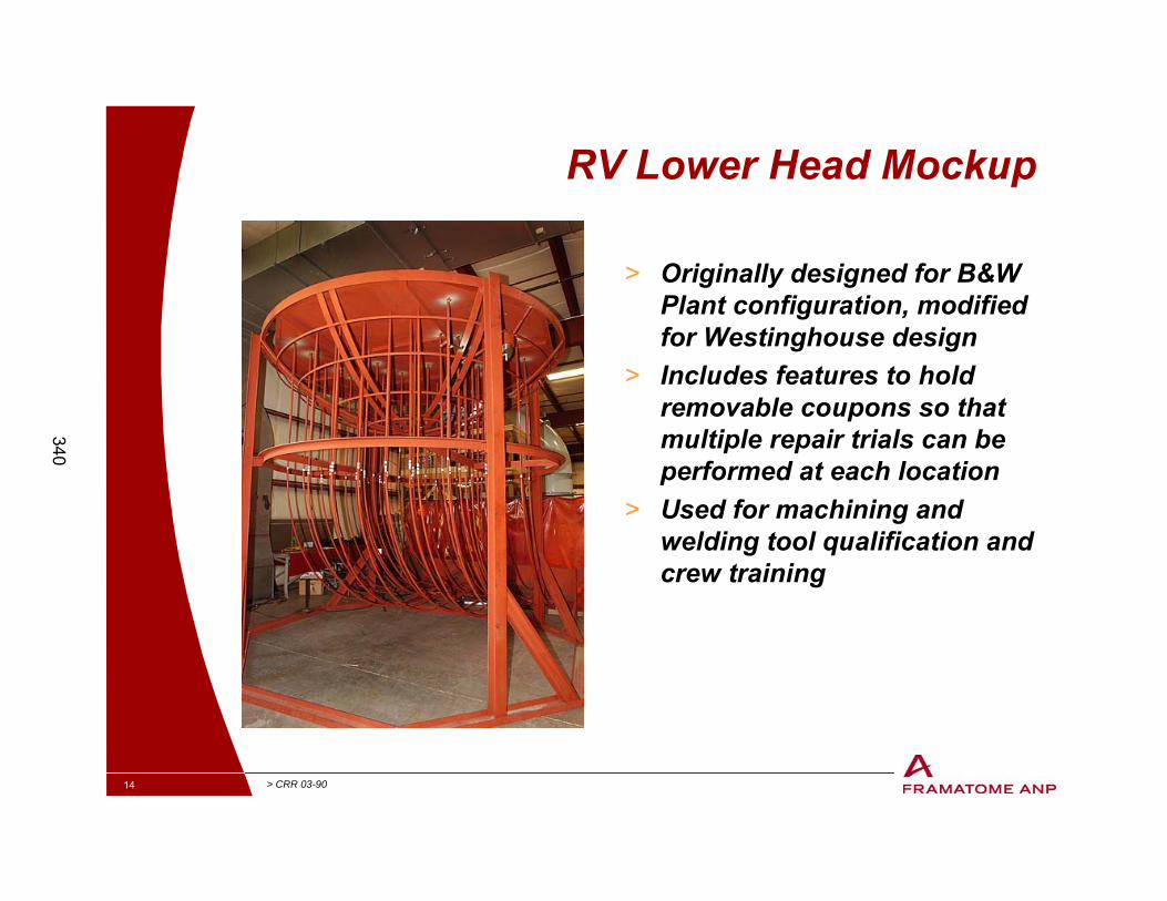
RV Lower Head Mockup
> Originally designed for B&W Plant configuration, modified for Westinghouse design
> Includes features to hold removable coupons so that multiple repair trials can be performed at each location
> Used for machining and welding tool qualification and crew training
340
15 > CRR 03-90
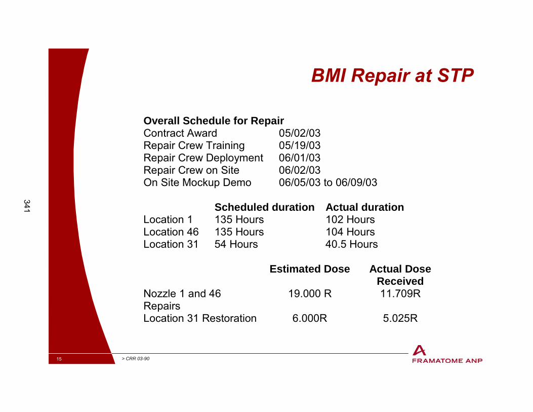
BMI Repair at STP
Overall Schedule for RepairContract Award 05/02/03 Repair Crew Training 05/19/03 Repair Crew Deployment 06/01/03 Repair Crew on Site 06/02/03 On Site Mockup Demo 06/05/03 to 06/09/03 Scheduled duration Actual duration Location 1 135 Hours 102 Hours Location 46 135 Hours 104 Hours Location 31 54 Hours 40.5 Hours Estimated Dose Actual Dose
Received Nozzle 1 and 46 Repairs
19.000 R 11.709R
Location 31 Restoration 6.000R 5.025R
341
16 > CRR 03-90
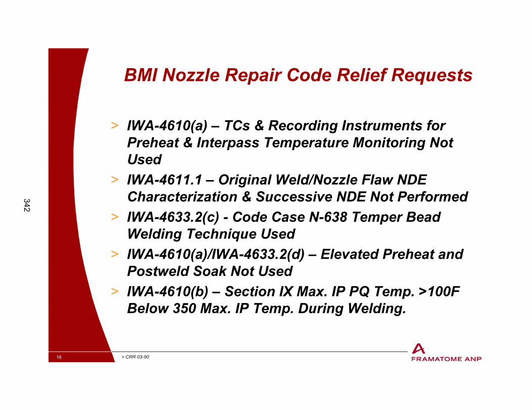
BMI Nozzle Repair Code Relief Requests
> IWA-4610(a) – TCs & Recording Instruments for Preheat & Interpass Temperature Monitoring Not Used
> IWA-4611.1 – Original Weld/Nozzle Flaw NDE Characterization & Successive NDE Not Performed
> IWA-4633.2(c) - Code Case N-638 Temper Bead Welding Technique Used
> IWA-4610(a)/IWA-4633.2(d) – Elevated Preheat and Postweld Soak Not Used
> IWA-4610(b) – Section IX Max. IP PQ Temp. >100F Below 350 Max. IP Temp. During Welding.
342
17 > CRR 03-90
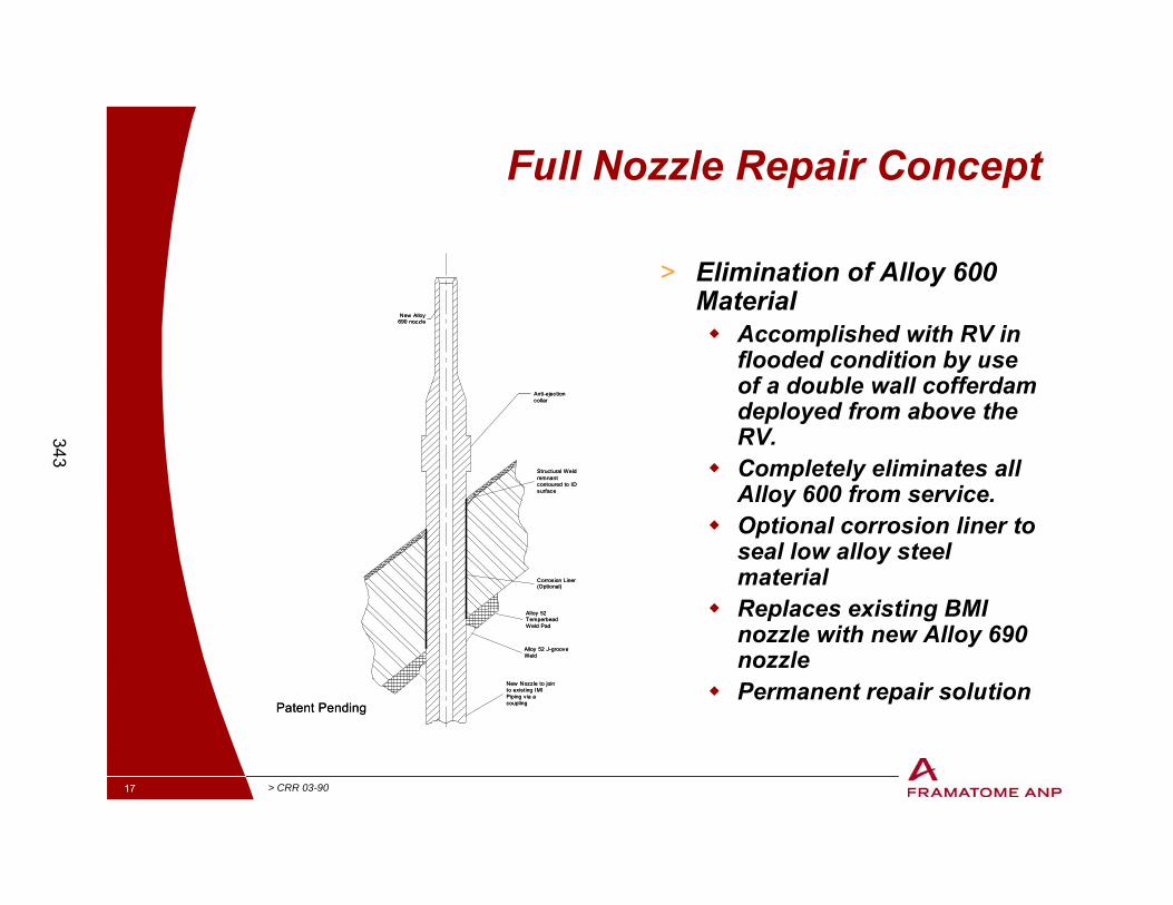
Full Nozzle Repair Concept
> Elimination of Alloy 600 Material� Accomplished with RV in
flooded condition by use of a double wall cofferdam deployed from above the RV.
� Completely eliminates all Alloy 600 from service.
� Optional corrosion liner to seal low alloy steel material
� Replaces existing BMI nozzle with new Alloy 690 nozzle
� Permanent repair solution
Anti-ejectioncollar
New Alloy690 nozzle
Structural Weldremnantcontoured to IDsurface
Alloy 52TemperbeadWeld Pad
Alloy 52 J-grooveWeld
New Nozzle to jointo existing IMIPiping via acoupling
Corrosion Liner(Optional)
Patent Pending
Anti-ejectioncollar
New Alloy690 nozzle
Structural Weldremnantcontoured to IDsurface
Alloy 52TemperbeadWeld Pad
Alloy 52 J-grooveWeld
New Nozzle to jointo existing IMIPiping via acoupling
Corrosion Liner(Optional)
Patent Pending
343
18 > CRR 03-90
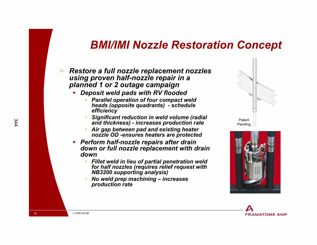
BMI/IMI Nozzle Restoration Concept
> Restore a full nozzle replacement nozzles using proven half-nozzle repair in a planned 1 or 2 outage campaign� Deposit weld pads with RV flooded
• Parallel operation of four compact weld heads (opposite quadrants) - schedule efficiency
• Significant reduction in weld volume (radial and thickness) - increases production rate
• Air gap between pad and existing heater nozzle OD -ensures heaters are protected
� Perform half-nozzle repairs after drain down or full nozzle replacement with drain down
• Fillet weld in lieu of partial penetration weld for half nozzles (requires relief request with NB3200 supporting analysis)
• No weld prep machining – increases production rate
Example of
Low Profile
Weld H
ead
Patent Pending
344

345

9/29/03 1
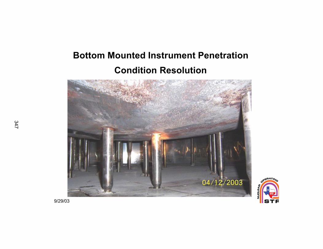
Bottom Mounted Instrument Penetration
Condition Resolution
347
9/29/03 2
Penetration #1
348
9/29/03 3
Penetration #46
349
9/29/03 4
Sample Analysis
Samples contained boron and elevated
concentrations of lithium
Samples did not contain any iron
Co-58 not present; therefore > 1 year old
Ratio of Cs-134 to Cs-137 indicates 3 - 5 years
350
9/29/03 5
Comprehensive Examination
• UT from penetration tube ID
• Enhanced visual exam of J-groove weld surface
• Volumetrically interrogate vessel base metal for wastage
• ET from penetration tube ID
• ET of J-groove weld surface
• Profilometry
• Borescope examinations
• Helium tests
• Metallurgical analyses of removed nozzle remnants
• Boat sample analyses
351
9/29/03 6
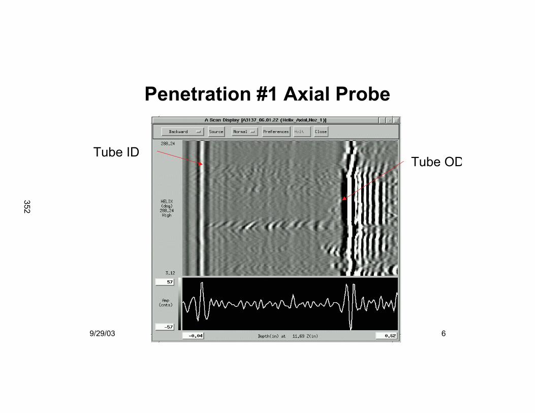
Penetration #1 Axial Probe
Tube IDTube OD
352
9/29/03 7
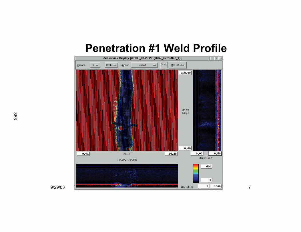
Penetration #1 Weld Profile
353
9/29/03 8
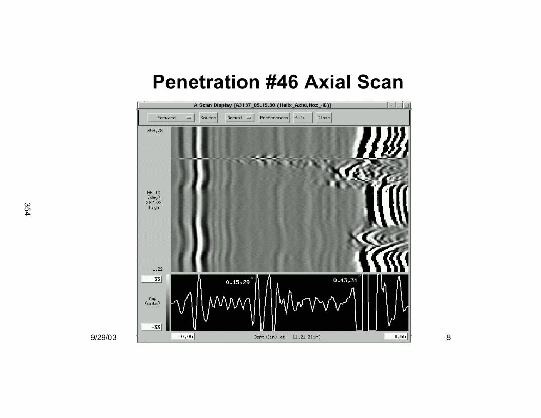
Penetration #46 Axial Scan
354
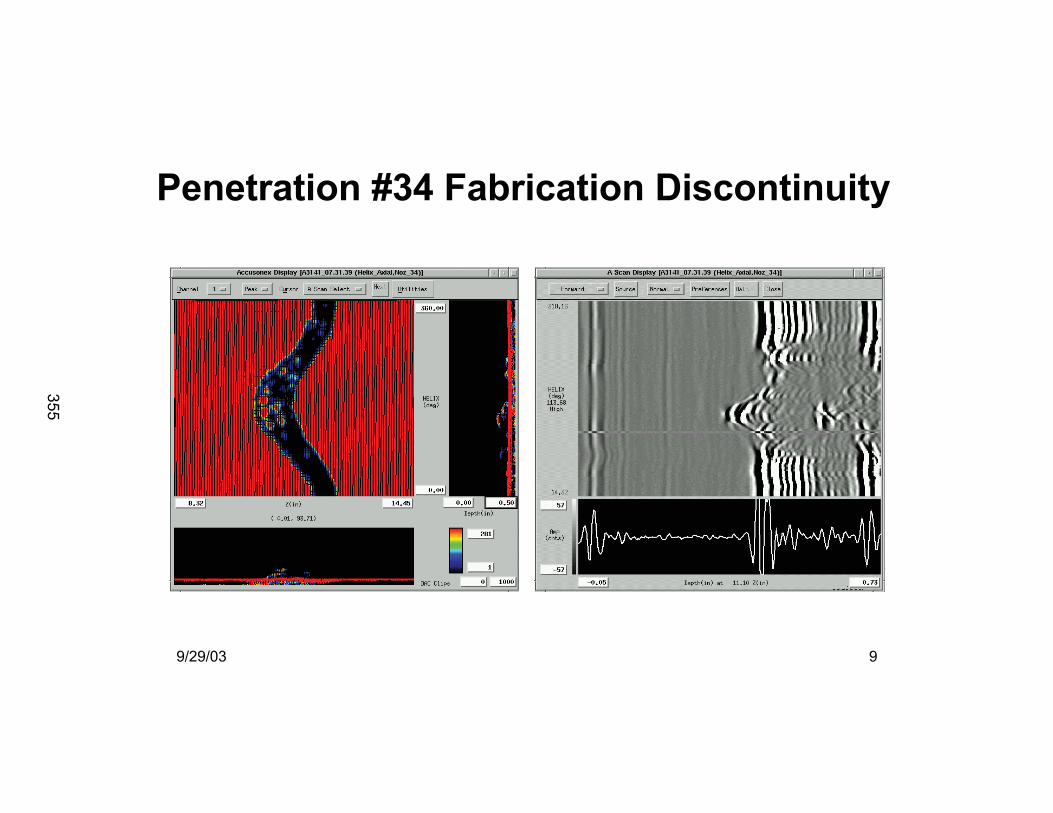
9/29/03 9
Penetration #34 Fabrication Discontinuity
355
9/29/03 10
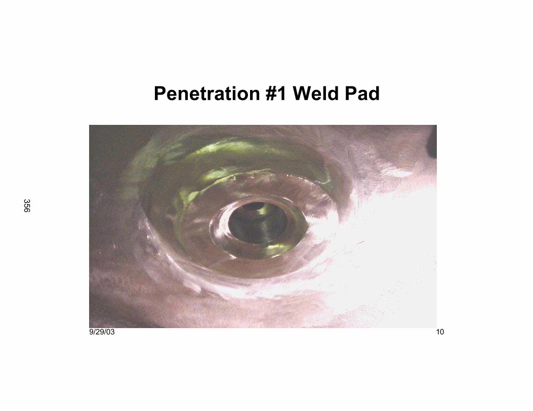
Penetration #1 Weld Pad
356
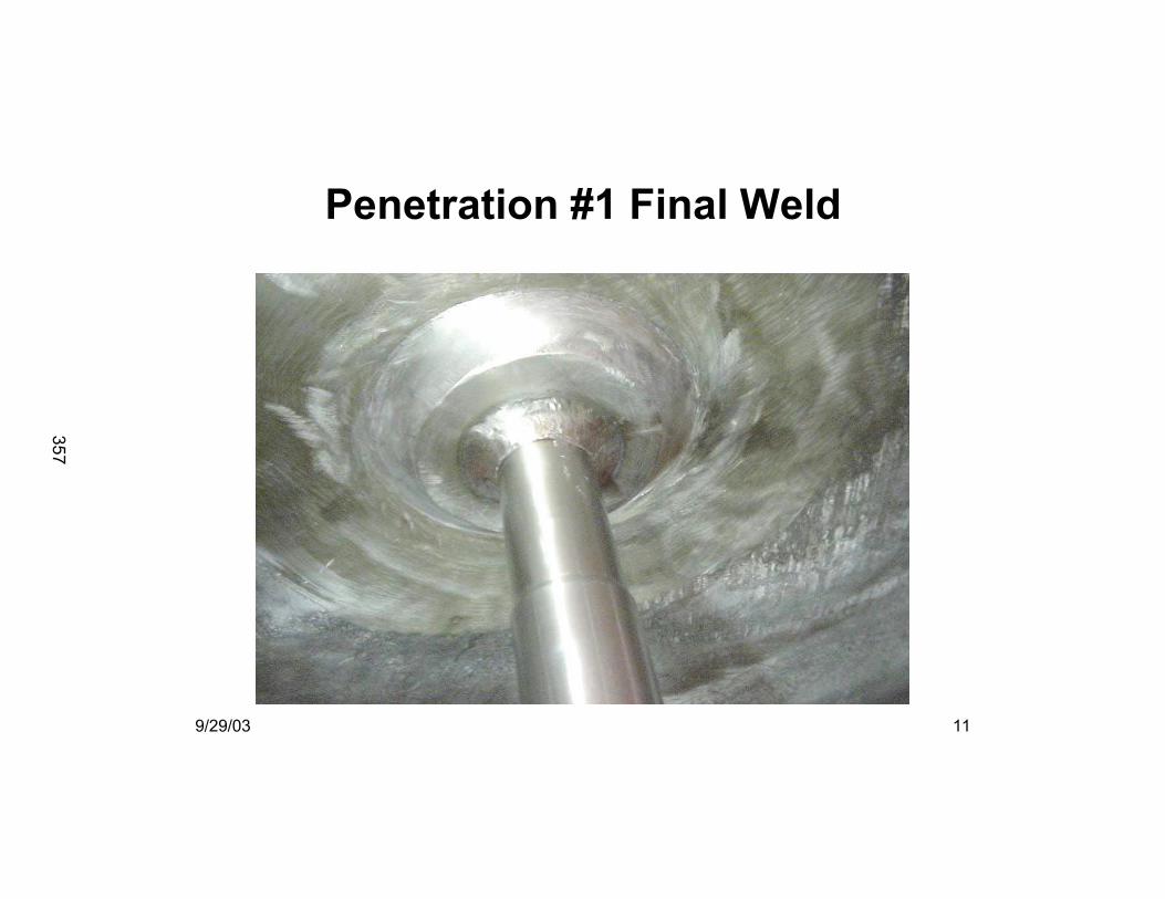
9/29/03 11
Penetration #1 Final Weld
357
9/29/03 12
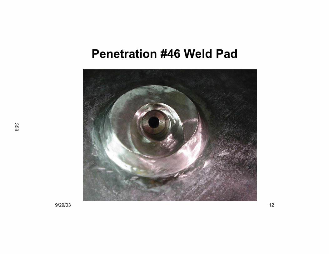
Penetration #46 Weld Pad
358
9/29/03 13
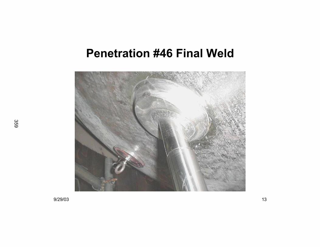
Penetration #46 Final Weld
359
9/29/03 14
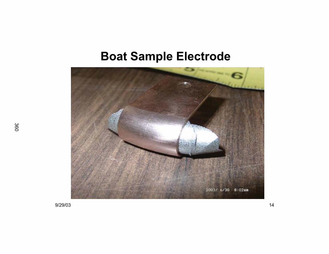
Boat Sample Electrode
360
9/29/03 15
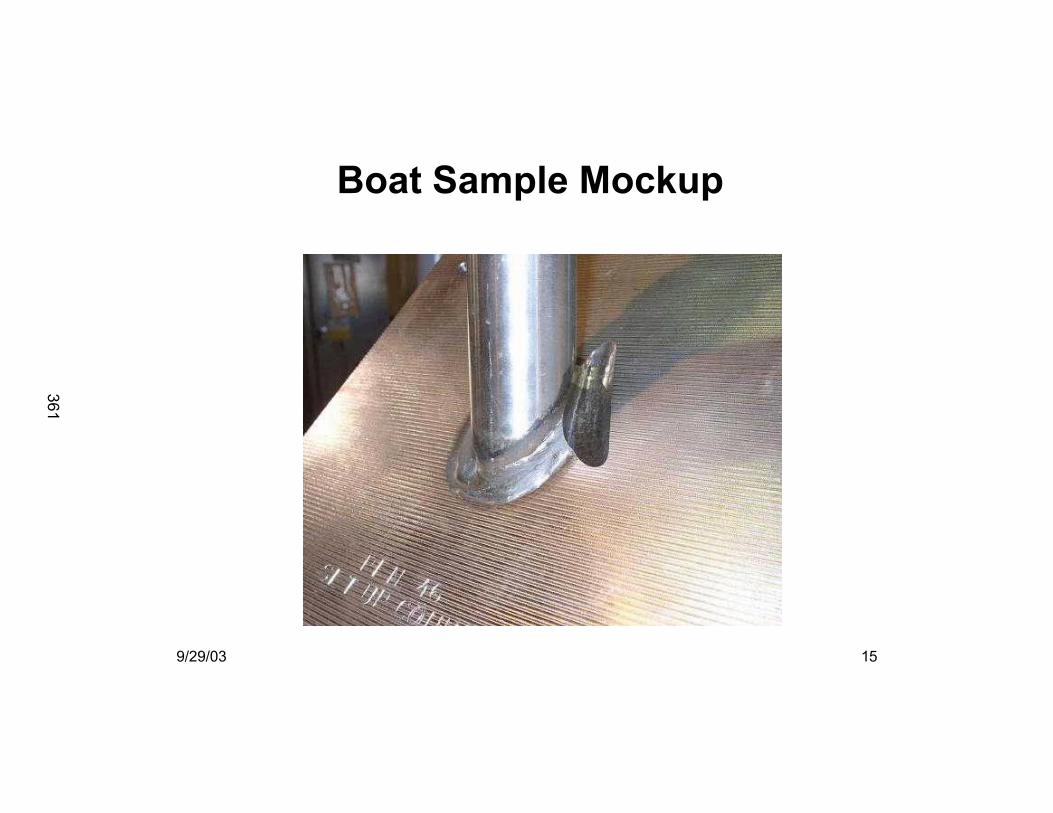
Boat Sample Mockup
361
9/29/03 16
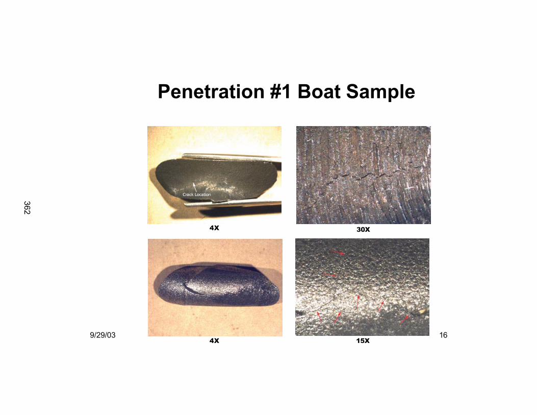
Penetration #1 Boat Sample
4X
4X 15X
30X
362
9/29/03 17
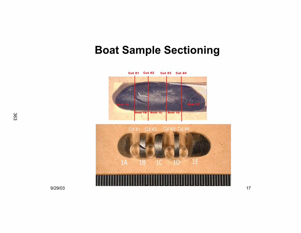
Boat Sample Sectioning
Boat 1A
Boat 1B Boat 1C Boat 1D
Boat 1E
Cut #1 Cut #2 Cut #3 Cut #4
363
9/29/03 18
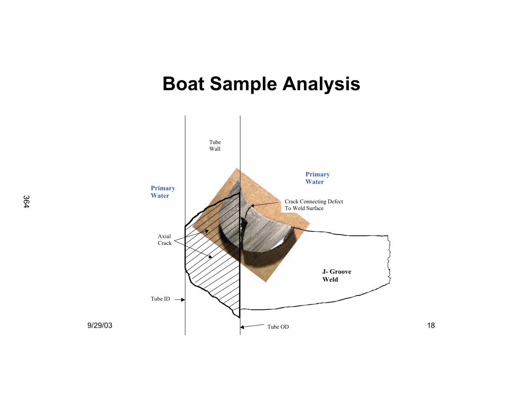
Boat Sample AnalysisBoat Sample Analysis
J- Groove
Weld
Tube OD
Tube ID
Axial
Crack
PrimaryWater
PrimaryWater
Tube
Wall
Crack Connecting Defect
To Weld Surface
364
9/29/03 19
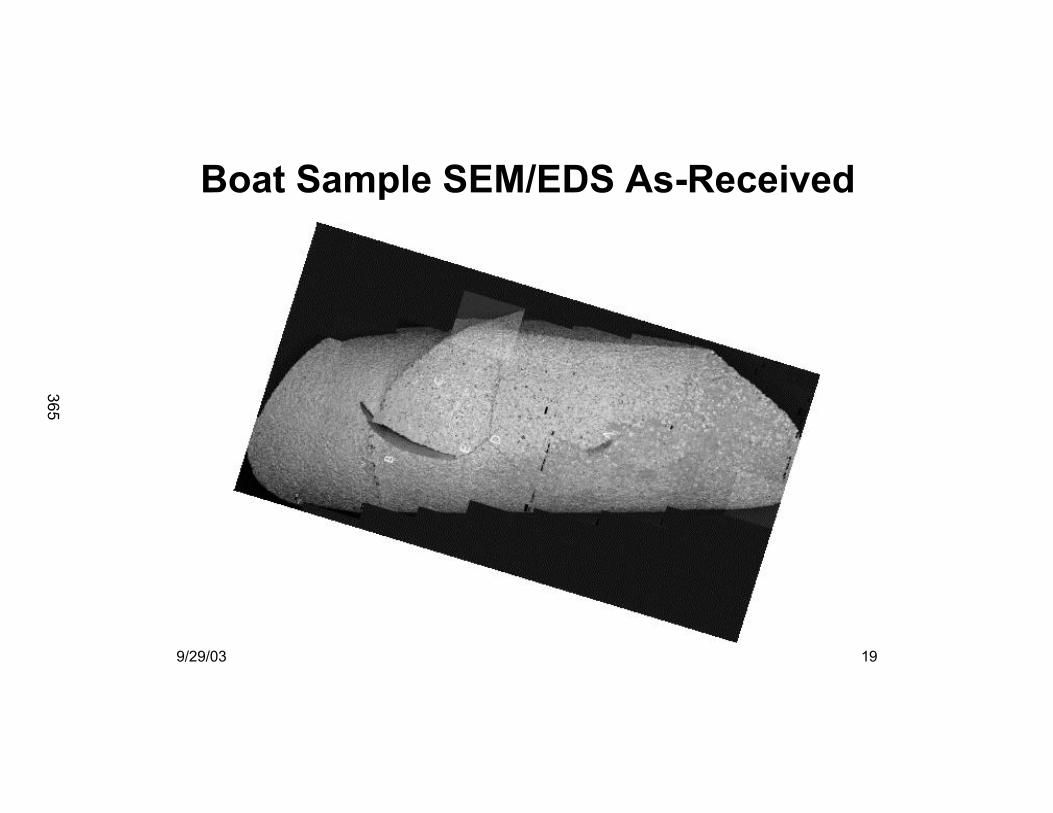
Boat Sample SEM/EDS As-Received
365
9/29/03 20
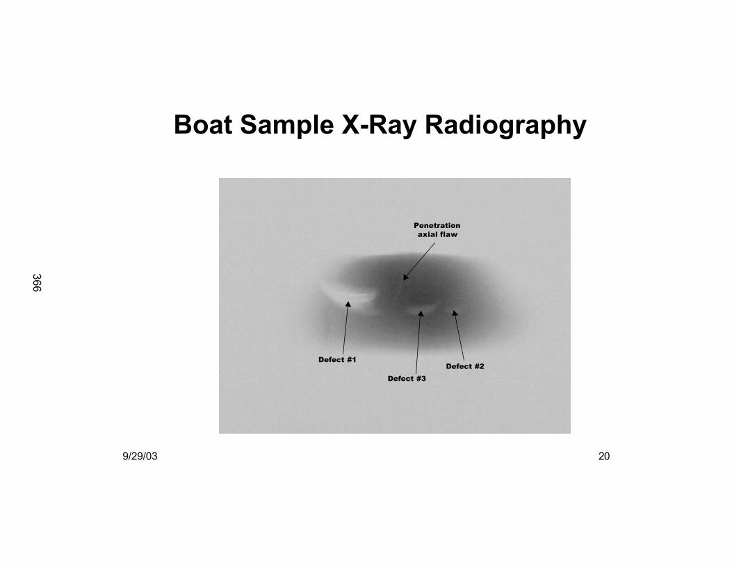
Boat Sample X-Ray Radiography
Defect #1
Defect #3
Defect #2
Penetration
axial flaw
366
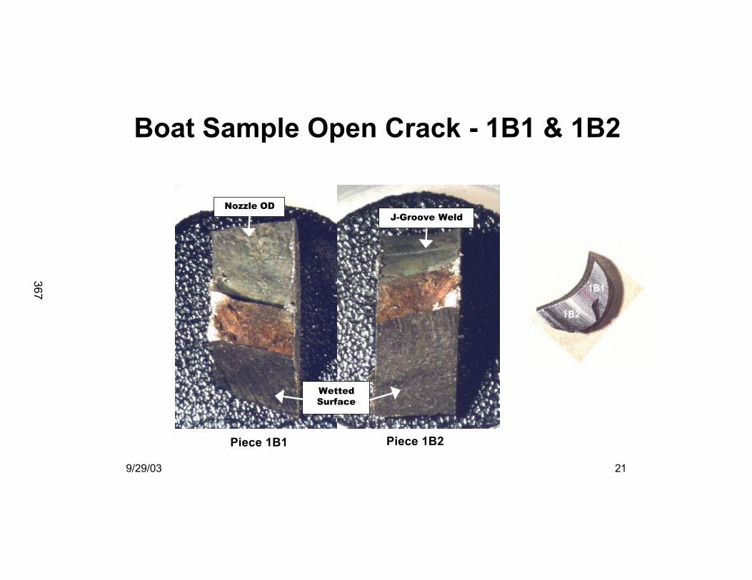
9/29/03 21
Boat Sample Open Crack - 1B1 & 1B2
Piece 1B1 Piece 1B2
Wetted
Surface
Nozzle OD
J-Groove Weld
1B2
367
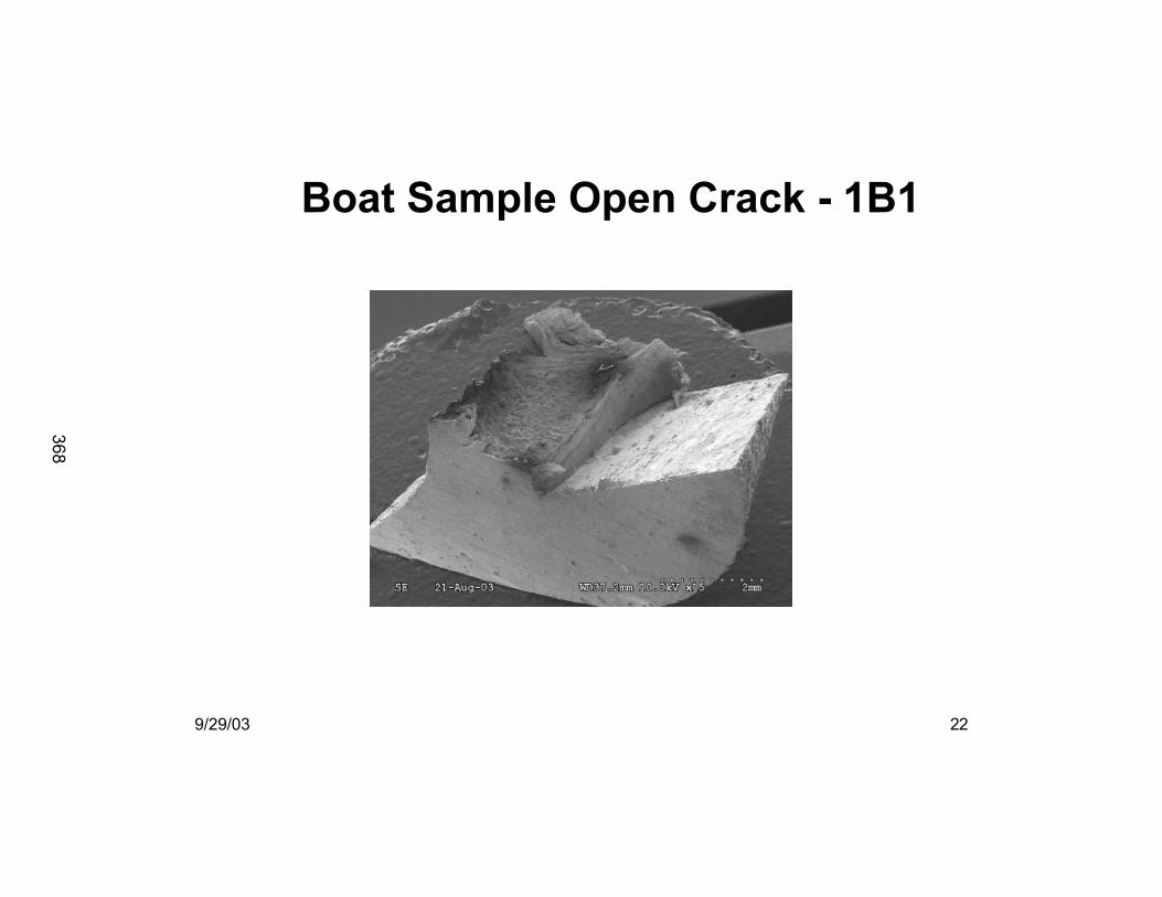
9/29/03 22
Boat Sample Open Crack - 1B1
368
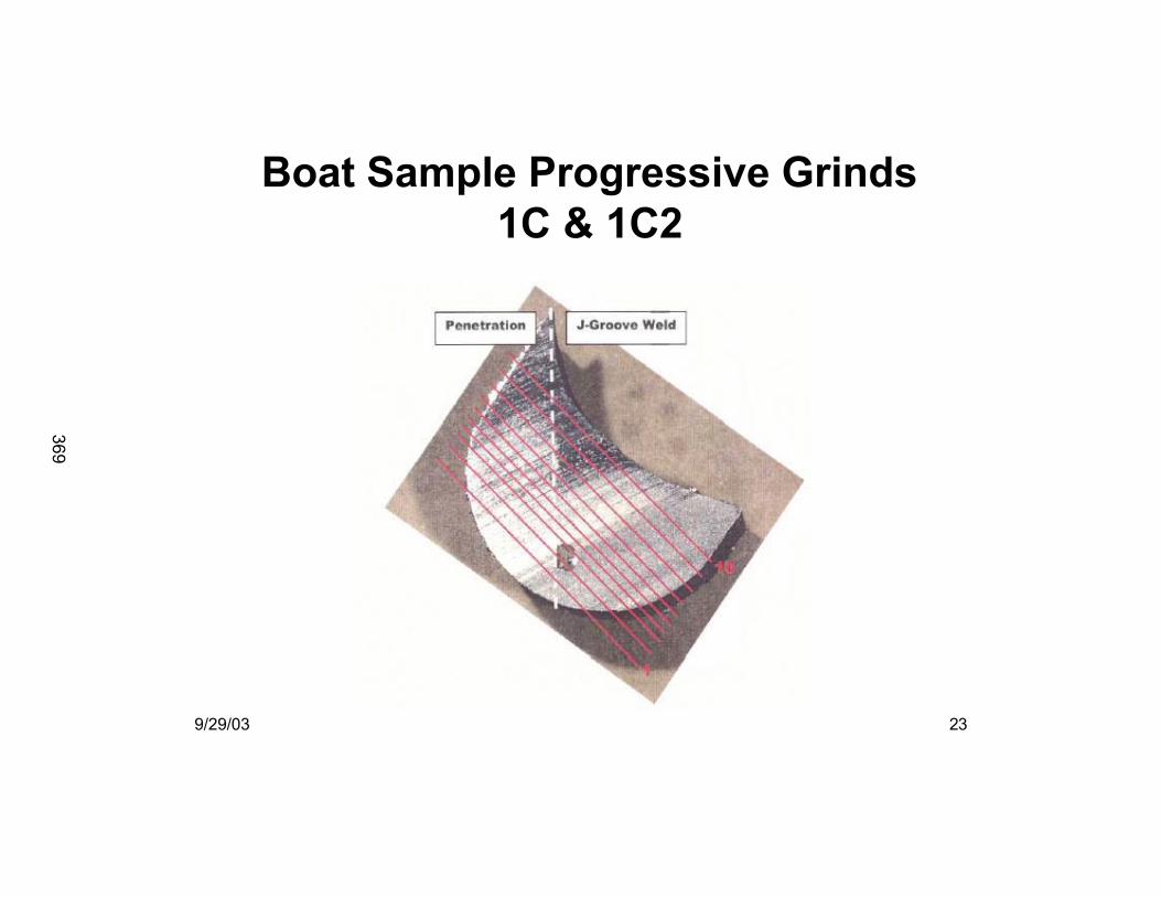
9/29/03 23
Boat Sample Progressive Grinds
1C & 1C2
369
9/29/03 24
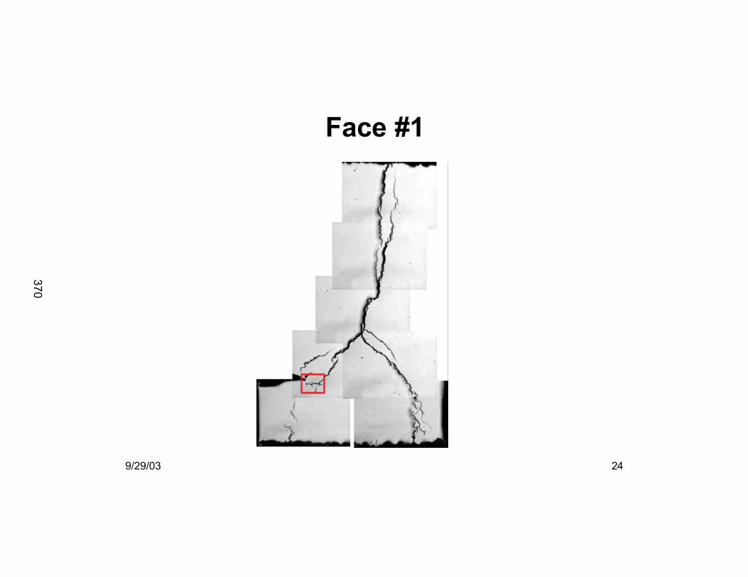
Face #1
370
9/29/03 25
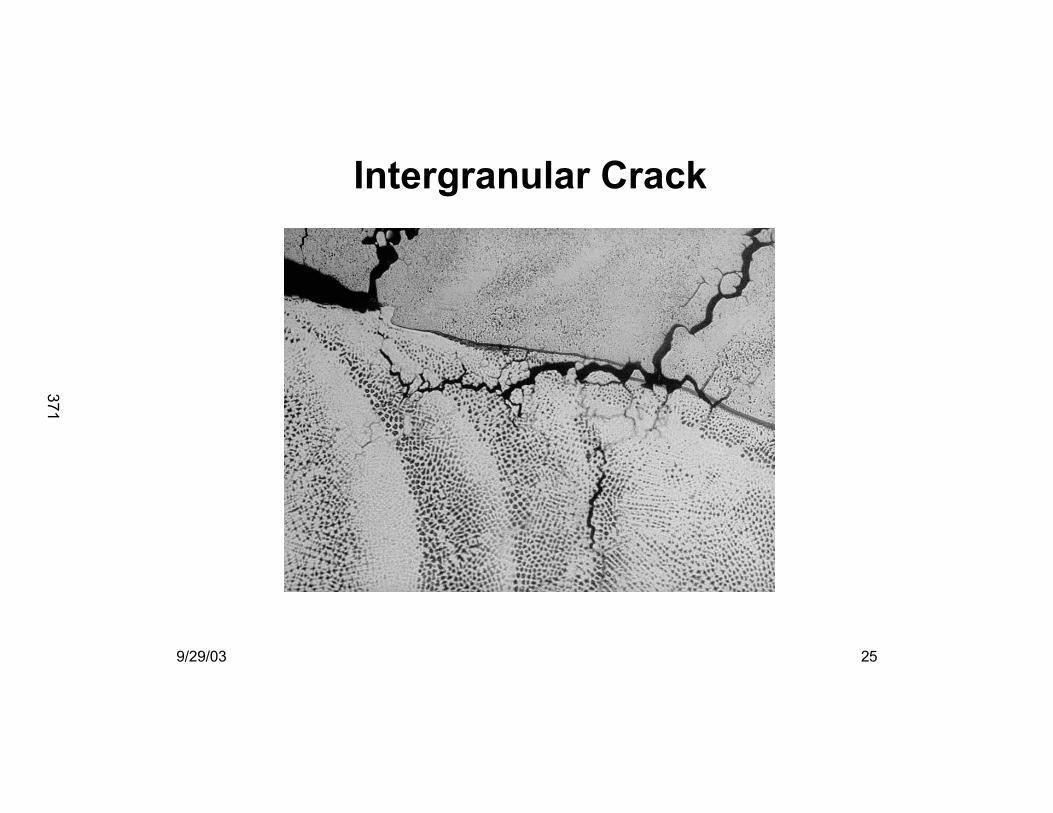
Intergranular Crack
371
9/29/03 26
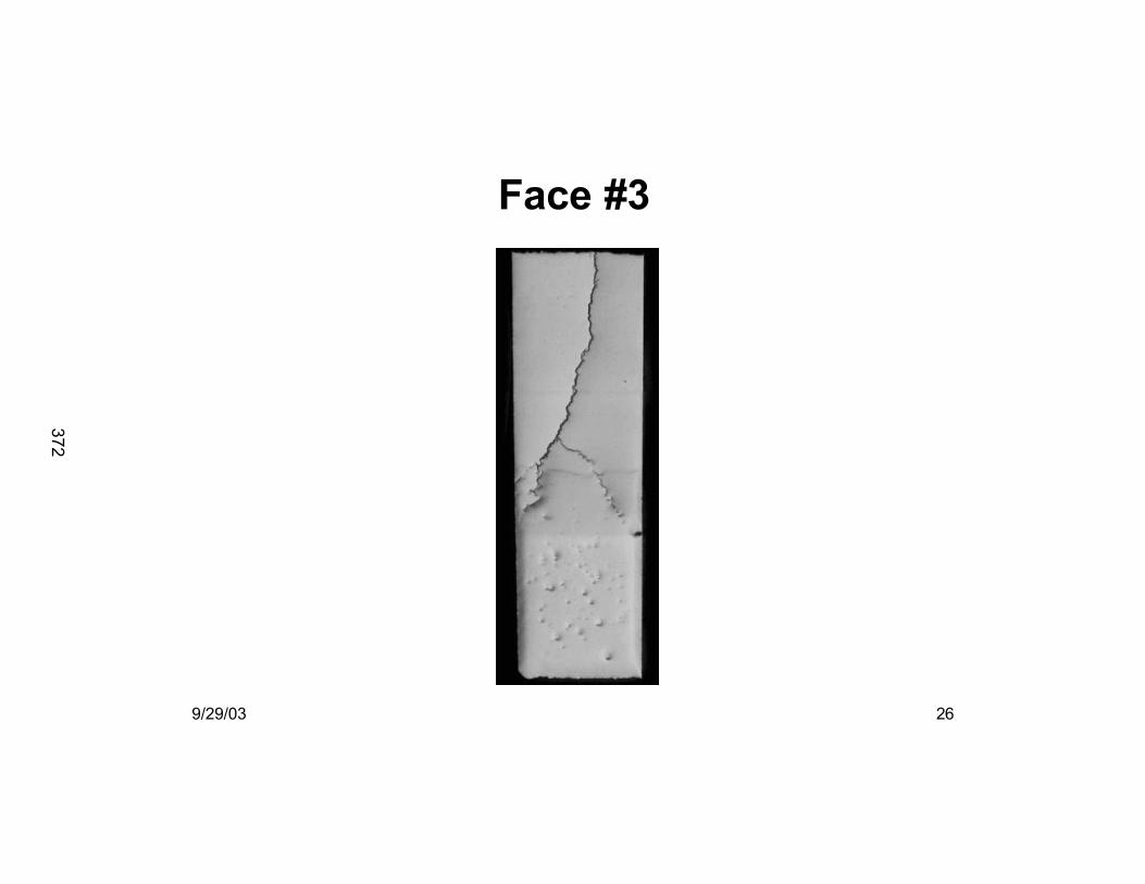
Face #3
372
9/29/03 27
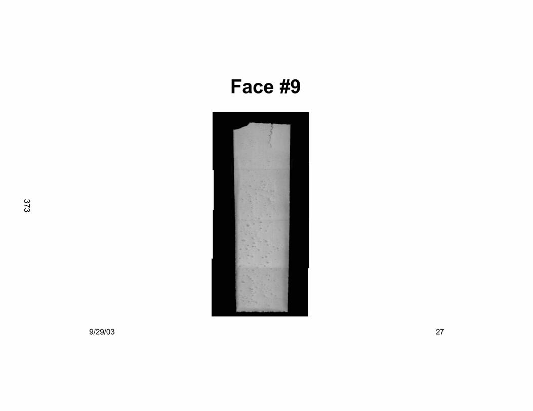
Face #9
373
9/29/03 28
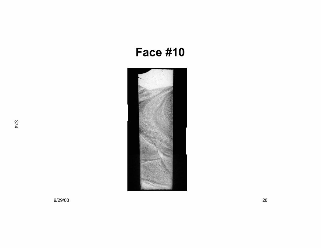
Face #10
374
9/29/03 29
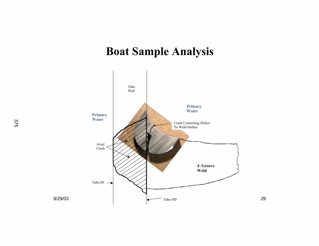
Boat Sample AnalysisBoat Sample Analysis
J- Groove
Weld
Tube OD
Tube ID
Axial
Crack
PrimaryWater
PrimaryWater
Tube
Wall
Crack Connecting Defect
To Weld Surface
375
9/29/03 30
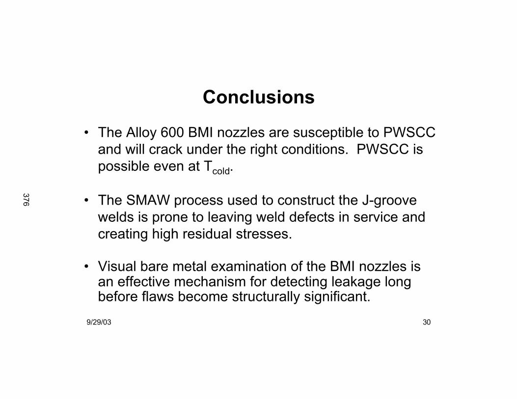
Conclusions
• The Alloy 600 BMI nozzles are susceptible to PWSCC
and will crack under the right conditions. PWSCC is
possible even at Tcold.
• The SMAW process used to construct the J-groove
welds is prone to leaving weld defects in service and
creating high residual stresses.
• Visual bare metal examination of the BMI nozzles isan effective mechanism for detecting leakage longbefore flaws become structurally significant.
376
9/29/03 31
Future STP Inspections
• Bare metal inspections
• Volumetric examination of Unit 2 penetrations
• Follow-up volumetric re-examination of Unit 1penetrations
377

Page 1
A BNFL Group company
379
Page 2
The Embedded Flaw Process for Repair of Reactor Vessel Head Penetrations
Warren Warren BamfordBamfordPaul Paul KreitmanKreitman
Westinghouse Electric CompanyWestinghouse Electric CompanySeptember 2003September 2003
380
Page 3
•• IntroductionIntroduction•• AttributesAttributes•• Basis for the embedded flaw concept Basis for the embedded flaw concept •• Basis for selection of Alloy 52 for repair weld Basis for selection of Alloy 52 for repair weld •• Experience with embedded flaw repairs Experience with embedded flaw repairs •• ConclusionsConclusions
381
Page 4
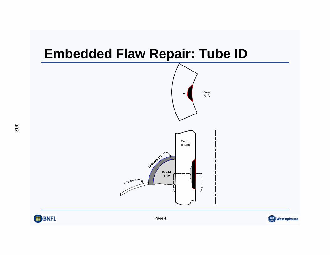
Embedded Flaw Repair: Tube ID
Vie wA-A
TubeA 6 0 0
W e ld8 2 /1 8 2
Bu tterin
g 182
W e ld1 8 2
Bu tterin
g 182
3 08 C la d
A A
382
Page 5
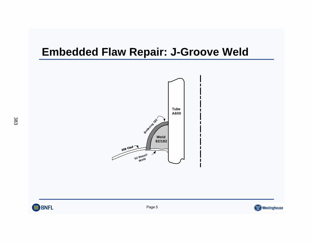
Embedded Flaw Repair: J-Groove Weld
TubeA600
Weld82/182
Butteri n
g 182
308 Clad
TubeA600
Weld82/182
308 Clad
52 Repair
Weld
383
Page 6
Introduction•• The Embedded Flaw repair was developed in 1993, and first The Embedded Flaw repair was developed in 1993, and first
implemented at DC Cook Unit 2 in the spring of 1996implemented at DC Cook Unit 2 in the spring of 1996•• The next repair was at North Anna 2, in the spring of 2001The next repair was at North Anna 2, in the spring of 2001•• The most recent repair was at Beaver Valley, in the spring of 20The most recent repair was at Beaver Valley, in the spring of 200202•• PlantPlant--specific relief requests were approved in each casespecific relief requests were approved in each case•• On December 12, 2001, Westinghouse submitted a generic relief On December 12, 2001, Westinghouse submitted a generic relief
request for an embedded flaw repair that could be applied to request for an embedded flaw repair that could be applied to CRDM/CEDM JCRDM/CEDM J--weld surfaces.weld surfaces.
•• NRC approved the process generically with an SER on July 3, NRC approved the process generically with an SER on July 3, 20032003
384
Page 7
Attributes•• Seals cracks from the environment, stopping PWSCCSeals cracks from the environment, stopping PWSCC•• Small thickness minimizes weld residual stressesSmall thickness minimizes weld residual stresses•• Welding can be done remotelyWelding can be done remotely•• Small amount of welding makes the repair timelySmall amount of welding makes the repair timely•• Weld repair is not needed structurally , since critical flaw Weld repair is not needed structurally , since critical flaw
sizes are very largesizes are very large•• Embedded Flaw repairs are permanent repairsEmbedded Flaw repairs are permanent repairs
385
Page 8
Basis for the Embedded Flaw ConceptWOG Weld Repair Program Begun in 1993
•• Investigate and provide a local and 360Investigate and provide a local and 360oo weld repair on weld repair on flawed material.flawed material.
•• Provide a design that is consistent with rules of ASME Provide a design that is consistent with rules of ASME Section XISection XI
•• Provide a weld process specification and repair design Provide a weld process specification and repair design packagepackage
386
Page 9
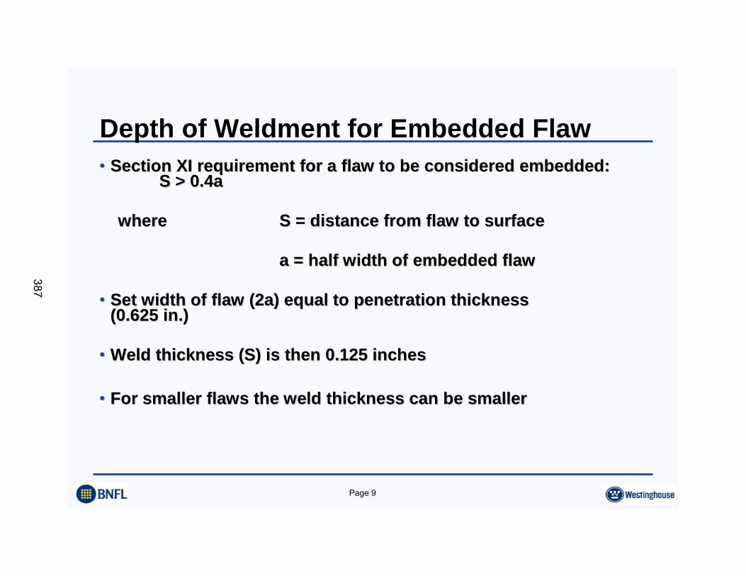
Depth of Weldment for Embedded Flaw•• Section XI requirement for a flaw to be considered embedded:Section XI requirement for a flaw to be considered embedded:
S > 0.4aS > 0.4a
wherewhere S = distance from flaw to surfaceS = distance from flaw to surface
a = half width of embedded flawa = half width of embedded flaw
•• Set width of flaw (2a) equal to penetration thicknessSet width of flaw (2a) equal to penetration thickness(0.625 in.)(0.625 in.)
•• Weld thickness (S) is then 0.125 inchesWeld thickness (S) is then 0.125 inches
•• For smaller flaws the weld thickness can be smallerFor smaller flaws the weld thickness can be smaller
387
Page 10
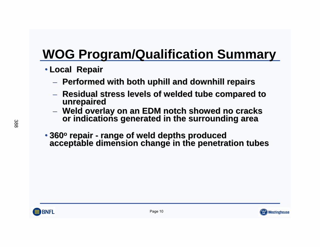
WOG Program/Qualification Summary•• Local RepairLocal Repair
–– Performed with both uphill and downhill repairsPerformed with both uphill and downhill repairs–– Residual stress levels of welded tube compared to Residual stress levels of welded tube compared to
unrepairedunrepaired–– Weld overlay on an EDM notch showed no cracks Weld overlay on an EDM notch showed no cracks
or indications generated in the surrounding areaor indications generated in the surrounding area
•• 360360oo repair repair -- range of weld depths produced range of weld depths produced acceptable dimension change in the penetration tubesacceptable dimension change in the penetration tubes
388
Page 11
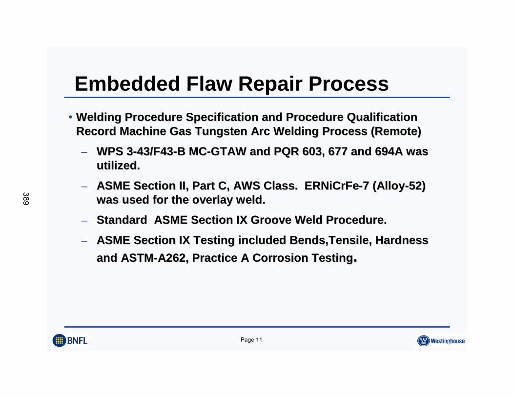
Embedded Flaw Repair Process•• Welding Procedure Specification and Procedure Qualification Welding Procedure Specification and Procedure Qualification
Record Machine Gas Tungsten Arc Welding Process (Remote)Record Machine Gas Tungsten Arc Welding Process (Remote)–– WPS 3WPS 3--43/F4343/F43--B MCB MC--GTAW and PQR 603, 677 and 694A was GTAW and PQR 603, 677 and 694A was
utilized.utilized.–– ASME Section II, Part C, AWS Class. ERNiCrFeASME Section II, Part C, AWS Class. ERNiCrFe--7 (Alloy7 (Alloy--52) 52)
was used for the overlay weld.was used for the overlay weld.–– Standard ASME Section IX Groove Weld Procedure.Standard ASME Section IX Groove Weld Procedure.–– ASME Section IX Testing included Bends,Tensile, Hardness ASME Section IX Testing included Bends,Tensile, Hardness
and ASTMand ASTM--A262, Practice A Corrosion TestingA262, Practice A Corrosion Testing..
389
Page 12
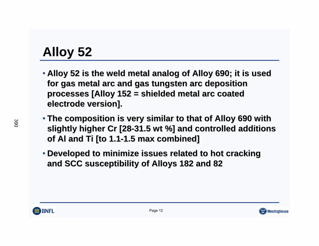
Alloy 52•• Alloy 52 is the weld metal analog of Alloy 690; it is used Alloy 52 is the weld metal analog of Alloy 690; it is used
for gas metal arc and gas tungsten arc deposition for gas metal arc and gas tungsten arc deposition processes [Alloy 152 = shielded metal arc coated processes [Alloy 152 = shielded metal arc coated electrode version].electrode version].
•• The composition is very similar to that of Alloy 690 with The composition is very similar to that of Alloy 690 with slightly higher Cr [28slightly higher Cr [28--31.5 wt %] and controlled additions 31.5 wt %] and controlled additions of Al and Ti [to 1.1of Al and Ti [to 1.1--1.5 max combined]1.5 max combined]
•• Developed to minimize issues related to hot cracking Developed to minimize issues related to hot cracking and SCC susceptibility of Alloys 182 and 82and SCC susceptibility of Alloys 182 and 82
390
Page 13
Alloy 52 - SCC Resistance•• Owing primarily to high Cr content, Alloys 52/152 and 690 exhibiOwing primarily to high Cr content, Alloys 52/152 and 690 exhibit t
apparent immunity to primary water stress corrosion cracking apparent immunity to primary water stress corrosion cracking (PWSCC)(PWSCC)
•• Service experience with Alloy 690 in SG heat transfer tubing, anService experience with Alloy 690 in SG heat transfer tubing, and d mechanical tube plug applications, and Alloys 52/152 as butterinmechanical tube plug applications, and Alloys 52/152 as buttering, g, cladding and weld filler materials has been exemplary, with no cladding and weld filler materials has been exemplary, with no reported degradation, after more than 15 years of servicereported degradation, after more than 15 years of service
•• Laboratory testing of each of these materials emphasizes the Laboratory testing of each of these materials emphasizes the corrosion resistance corrosion resistance -- no known incidence of crack initiation or no known incidence of crack initiation or crack propagation in primary water environmentscrack propagation in primary water environments
391
Page 14
Embedded Flaw Service Experience:D C Cook Unit 2
•• Pen. 75 found to have ID surface flaw in 1994Pen. 75 found to have ID surface flaw in 1994•• Depth approx. 40 percent of wall thicknessDepth approx. 40 percent of wall thickness•• Embedded Flaw Repair implemented in 1996Embedded Flaw Repair implemented in 1996•• Repair reRepair re--inspected in Jan. 2002: No inspected in Jan. 2002: No Indications on the weld repairIndications on the weld repair
392
Page 15
North Anna Implementation•• As a result of observed leakage on one of these penetrations in As a result of observed leakage on one of these penetrations in
2002, all three penetrations were re2002, all three penetrations were re--examined. Evidence of flaws examined. Evidence of flaws was observedwas observed
•• An evaluation of these three repairs has been completed, with thAn evaluation of these three repairs has been completed, with the e following conclusions:following conclusions:–– The weld repairs did not achieve full coverage of the Alloy The weld repairs did not achieve full coverage of the Alloy
82/182 wetted surface82/182 wetted surface–– These exposed Alloy 82/182 surfaces are the location of These exposed Alloy 82/182 surfaces are the location of
indications found in 2002indications found in 2002•• Lessons learned and corrective actions have been implemented.Lessons learned and corrective actions have been implemented.
393
Page 16
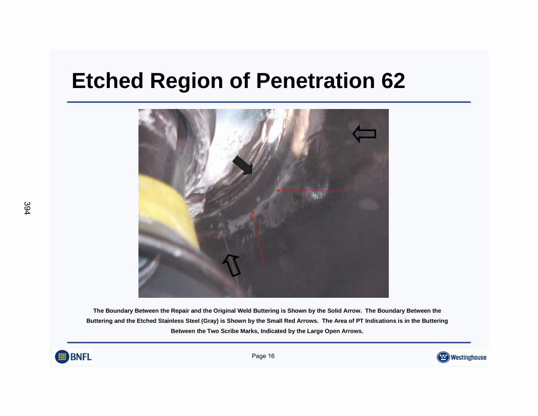
Etched Region of Penetration 62
The Boundary Between the Repair and the Original Weld Buttering is Shown by the Solid Arrow. The Boundary Between theButtering and the Etched Stainless Steel (Gray) is Shown by the Small Red Arrows. The Area of PT Indications is in the Buttering
Between the Two Scribe Marks, Indicated by the Large Open Arrows.
394
Page 17
SER on Embedded Flaw Repairs•• Technical Basis submitted via WCAP 15987; to become 15987ATechnical Basis submitted via WCAP 15987; to become 15987A•• SER issued July 3, 2003SER issued July 3, 2003•• Approved a nonApproved a non--structural (seal) weld repair, of unspecified thicknessstructural (seal) weld repair, of unspecified thickness•• Three layers of weld required on attachment weld repairs, and twThree layers of weld required on attachment weld repairs, and two layers o layers
for the tube ID or ODfor the tube ID or OD•• SER acceptance was based on Westinghouse application of current SER acceptance was based on Westinghouse application of current ASME ASME
Code fracture mechanics methodsCode fracture mechanics methods•• The SER states that the embedded flaw repair is approved for appThe SER states that the embedded flaw repair is approved for application lication
to CE and Westinghouse designsto CE and Westinghouse designs
395
Page 18
SER on Embedded Flaw Repairs•• At or Above the WeldAt or Above the Weld
–– The repair can be used for any flaws in the tube (ID or OD) thatThe repair can be used for any flaws in the tube (ID or OD) that meet the ASME meet the ASME Section XI acceptance criteria, which were endorsed by the NRC bSection XI acceptance criteria, which were endorsed by the NRC by letter to NEI on y letter to NEI on April 11, 2003.April 11, 2003.
–– Larger flaws on the tube ID, are to be dealt with on a plantLarger flaws on the tube ID, are to be dealt with on a plant--specific basisspecific basis
–– Circumferential flaws in the tube above the weld, regardless of Circumferential flaws in the tube above the weld, regardless of size are treated on a size are treated on a plantplant--specific basis, consistent with previous NRC approachesspecific basis, consistent with previous NRC approaches
•• Below the weldBelow the weld–– Larger flaws on the tube below the weld are approved, regardlessLarger flaws on the tube below the weld are approved, regardless of size, provided of size, provided
their upper extremity does not reach the bottom of the weldtheir upper extremity does not reach the bottom of the weld
•• In the WeldIn the Weld–– The repair can be used for flaws of any type in the attachment wThe repair can be used for flaws of any type in the attachment weldeld
396
Page 19
SER Requirements•• Inspections are consistent with those for a structural weld, reqInspections are consistent with those for a structural weld, requiring both uiring both
UT and surface exams in most casesUT and surface exams in most cases
•• Inspections must be performed by qualified inspectorsInspections must be performed by qualified inspectors
•• Licensees must demonstrate that a plantLicensees must demonstrate that a plant--specific application is bounded specific application is bounded by the WCAP (15987, Rev. 2), including the ASME Code fracture by the WCAP (15987, Rev. 2), including the ASME Code fracture mechanics evaluation contained in Appendix C of the WCAP (see SEmechanics evaluation contained in Appendix C of the WCAP (see SER R paragraph 3.6)paragraph 3.6)
397
Page 20
Conclusions•• Embedded Flaw Repair process is now fully Embedded Flaw Repair process is now fully developeddeveloped
•• Implementation is qualifiedImplementation is qualified•• Good service experience Good service experience •• SER received from NRC, July 2003SER received from NRC, July 2003
398

Page 21
A BNFL Group company
399

Weld Overlay to Reduce Tensile Stresses inAlloy 82/182 Butt Welds
Vessel Head Penetration Inspection, Cracking and Repair ConferenceSeptember 29 – October 2, 2003
Gaithersburg, MD
by:Steve Hunt, Dominion Engineering, Inc.
John Broussard, Dominion Engineering, Inc.Stephen Ahnert, Dominion Engineering, Inc.
Patrick O'Regan, EPRIDana Covill, Progress Energy
401
NRC Alloy 600 Conference Slide 2
Contents
• Background• Weld Overlay to Reduce Tensile Stress• Finite Element Model• Welding Residual Stresses• Operating Stresses – As-Designed• Operating Stresses – With Inside Surface Weld Repairs• Operating Stresses – With Outside Surface Weld Overlay• Summary of Results
402
NRC Alloy 600 Conference Slide 3
Background
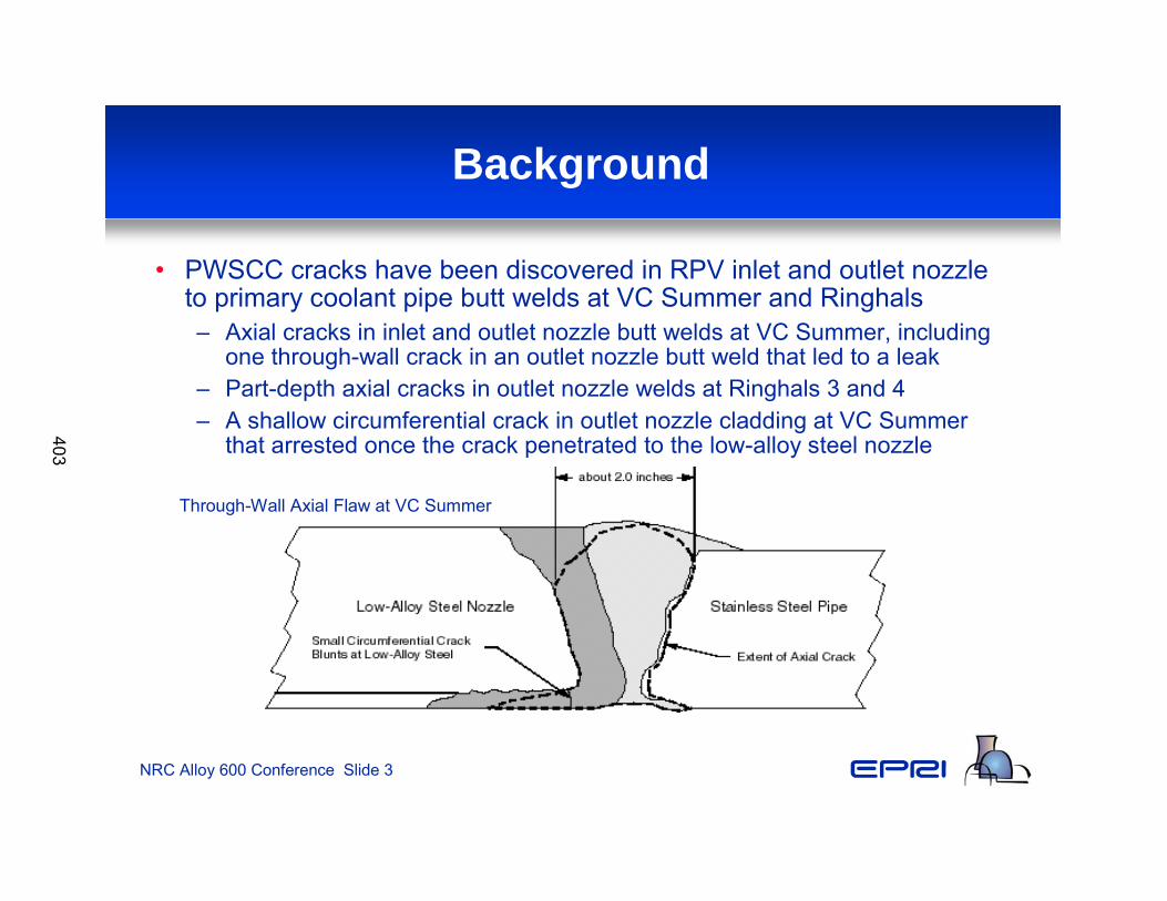
• PWSCC cracks have been discovered in RPV inlet and outlet nozzleto primary coolant pipe butt welds at VC Summer and Ringhals– Axial cracks in inlet and outlet nozzle butt welds at VC Summer, including
one through-wall crack in an outlet nozzle butt weld that led to a leak– Part-depth axial cracks in outlet nozzle welds at Ringhals 3 and 4– A shallow circumferential crack in outlet nozzle cladding at VC Summer
that arrested once the crack penetrated to the low-alloy steel nozzle
Through-Wall Axial Flaw at VC Summer
403
NRC Alloy 600 Conference Slide 4
Background
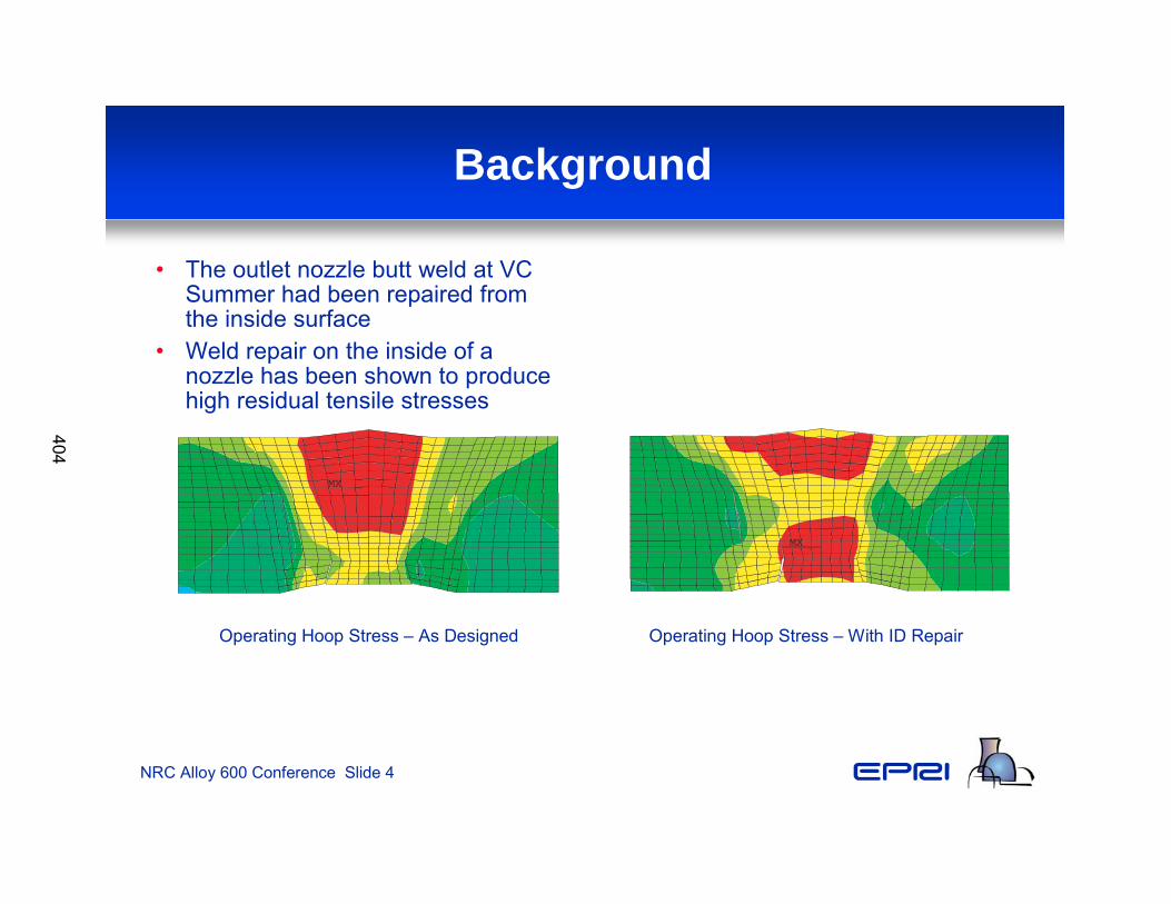
• The outlet nozzle butt weld at VC Summer had been repaired from the inside surface
• Weld repair on the inside of a nozzle has been shown to produce high residual tensile stresses
MX
Operating Hoop Stress – As Designed Operating Hoop Stress – With ID Repair
MX
404
NRC Alloy 600 Conference Slide 5
Weld Overlay to Reduce Tensile Stress
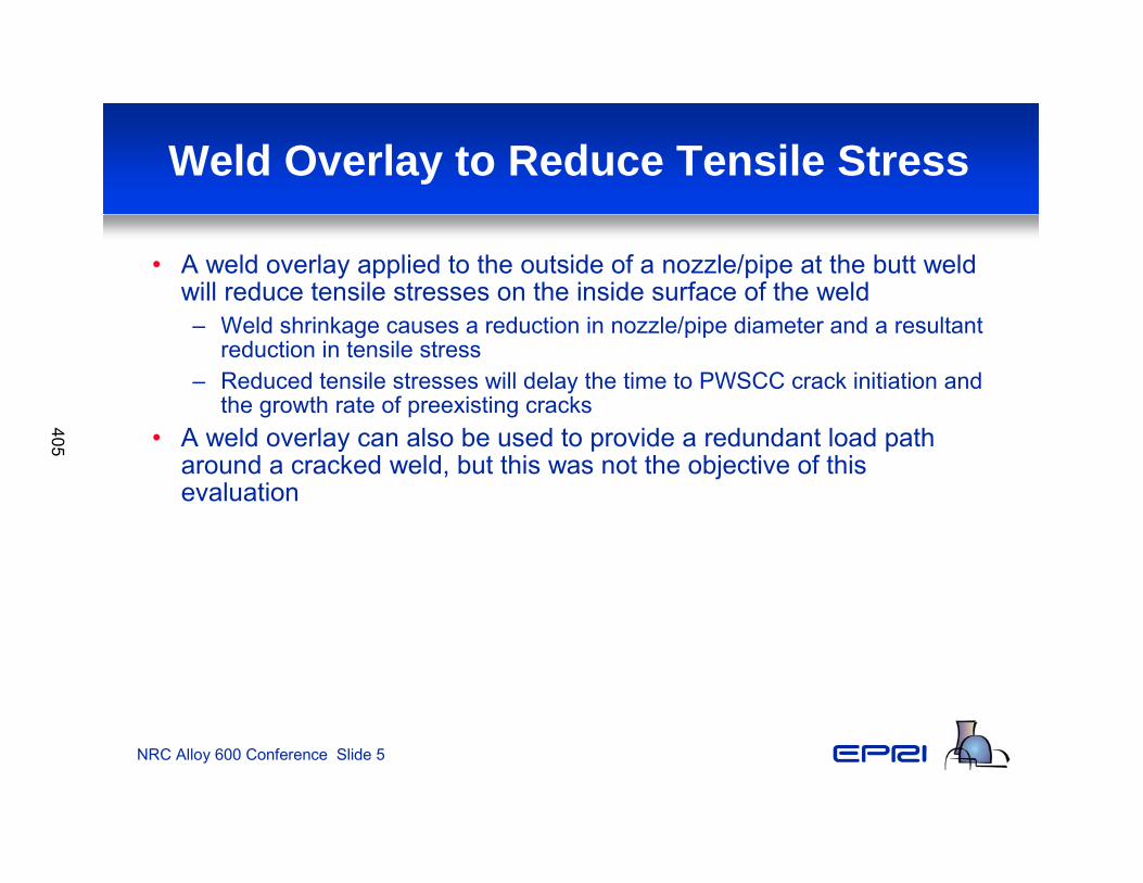
• A weld overlay applied to the outside of a nozzle/pipe at the butt weld will reduce tensile stresses on the inside surface of the weld– Weld shrinkage causes a reduction in nozzle/pipe diameter and a resultant
reduction in tensile stress– Reduced tensile stresses will delay the time to PWSCC crack initiation and
the growth rate of preexisting cracks • A weld overlay can also be used to provide a redundant load path
around a cracked weld, but this was not the objective of this evaluation
405
NRC Alloy 600 Conference Slide 6
Weld Overlay to Reduce Tensile Stress
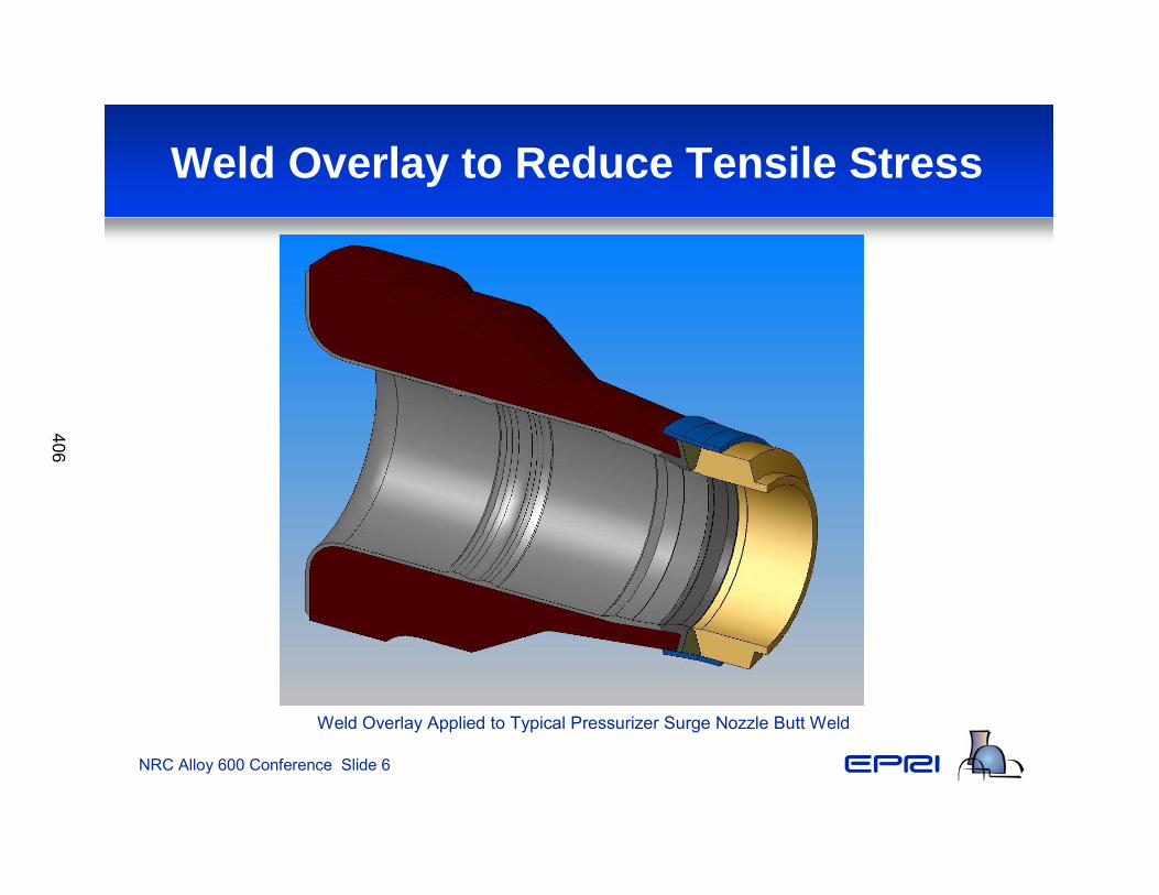
Weld Overlay Applied to Typical Pressurizer Surge Nozzle Butt Weld
406
NRC Alloy 600 Conference Slide 7
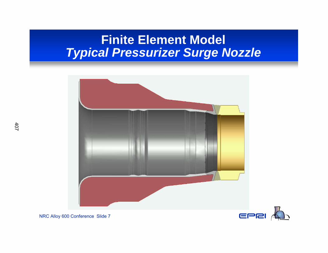
Finite Element ModelTypical Pressurizer Surge Nozzle
407
NRC Alloy 600 Conference Slide 8
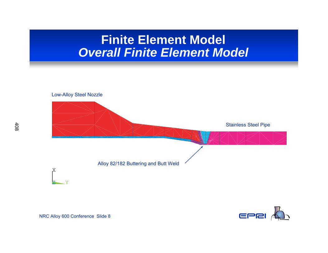
Finite Element ModelOverall Finite Element Model
X
YZ
Stainless Steel Pipe
Low-Alloy Steel Nozzle
Alloy 82/182 Buttering and Butt Weld
408
NRC Alloy 600 Conference Slide 9
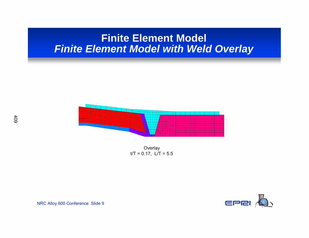
Finite Element ModelFinite Element Model with Weld Overlay
Overlayt/T = 0.17, L/T = 5.5
409
NRC Alloy 600 Conference Slide 10
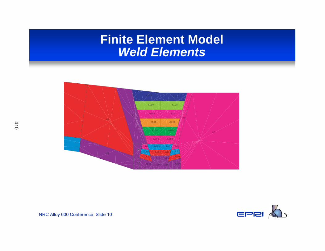
Finite Element ModelWeld Elements
A3
A2
A2
A2
A200
A201
A202
A203
A2
A200 A200 A200
A201
A202
A203
A5
A5
A101 A101
A102 A102
A103 A103
A104 A104
A105 A105
A106 A106
A107 A107
A108 A108
A109 A109
410
NRC Alloy 600 Conference Slide 11
Finite Element ModelAnalysis Approach
• Weld applied using methodology described in previous Dominion Engineering paper, Welding Residual and Operating Stress Analysis of RPV Top and Bottom Head Nozzle– Thermal and stress analysis of each pass– 6-11 passes applied depending on nozzle geometry
• Weld backgouged from the inside surface approximately 1/3 wall thickness
• Backgouged area weld repaired from the inside surface using 2-4 passes depending on nozzle geometry
• Completed joint subjected to hydrostatic test conditions (3,125 psi)• Operating pressure (2,250 psi) and temperature (615°F) applied
411
NRC Alloy 600 Conference Slide 12
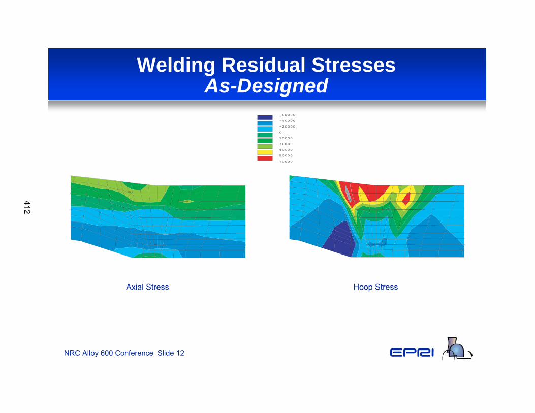
Welding Residual StressesAs-Designed
MN
MX
Axial Stress Hoop Stress
MN
MX
-60000
-40000
-20000
0
15000
30000
40000
50000
70000
412
NRC Alloy 600 Conference Slide 13
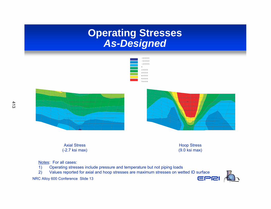
Operating StressesAs-Designed
MN
MX
MN
MX
Axial Stress(-2.7 ksi max)
Hoop Stress(9.0 ksi max)
Notes: For all cases:1) Operating stresses include pressure and temperature but not piping loads2) Values reported for axial and hoop stresses are maximum stresses on wetted ID surface
-60000
-40000
-20000
0
15000
30000
40000
50000
70000
413
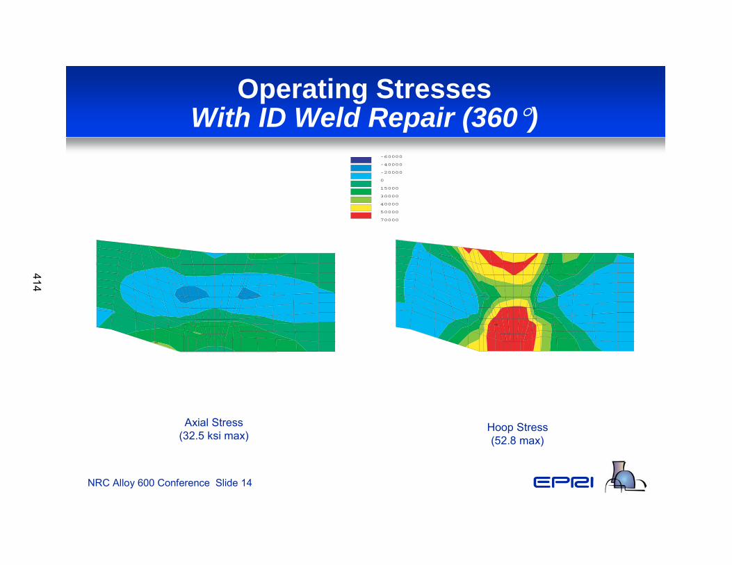
NRC Alloy 600 Conference Slide 14
Operating StressesWith ID Weld Repair (360°)
MX
Axial Stress(32.5 ksi max)
Hoop Stress(52.8 max)
MX
-60000
-40000
-20000
0
15000
30000
40000
50000
70000
414
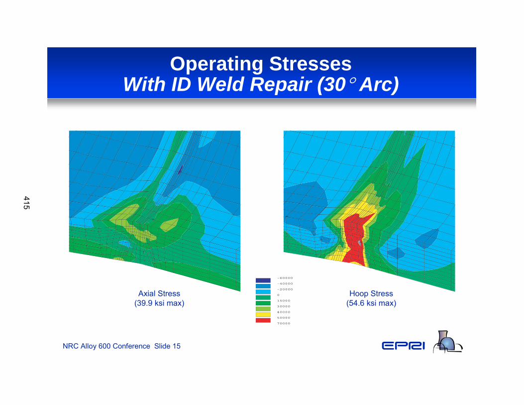
NRC Alloy 600 Conference Slide 15
Operating StressesWith ID Weld Repair (30° Arc)
1
MN
MX
Axial Stress(39.9 ksi max)
Hoop Stress(54.6 ksi max)
1
MN
MX
-60000
-40000
-20000
0
15000
30000
40000
50000
70000
415
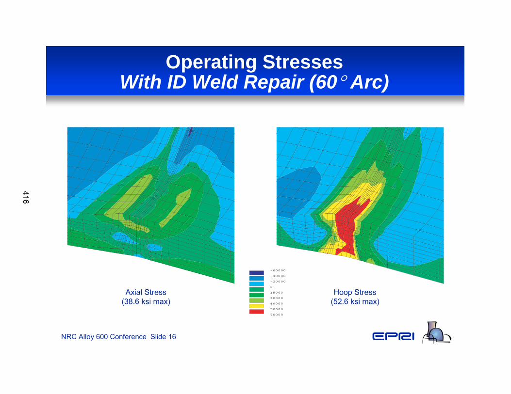
NRC Alloy 600 Conference Slide 16
Operating StressesWith ID Weld Repair (60° Arc)
1 MN
MX
Axial Stress(38.6 ksi max)
Hoop Stress(52.6 ksi max)
1
MX
-60000
-40000
-20000
0
15000
30000
40000
50000
70000
416
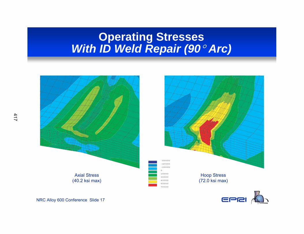
NRC Alloy 600 Conference Slide 17
Operating StressesWith ID Weld Repair (90° Arc)
1
MX
Axial Stress(40.2 ksi max)
Hoop Stress(72.0 ksi max)
1
MX
-60000
-40000
-20000
0
15000
30000
40000
50000
70000
417

NRC Alloy 600 Conference Slide 18
Operating StressesWith Weld Overlay – As-Designed
MN
MX
Axial Stress(-8.6 ksi max)
Hoop Stress(-23.2 ksi max)
MN
MX
-60000
-40000
-20000
0
15000
30000
40000
50000
70000
418
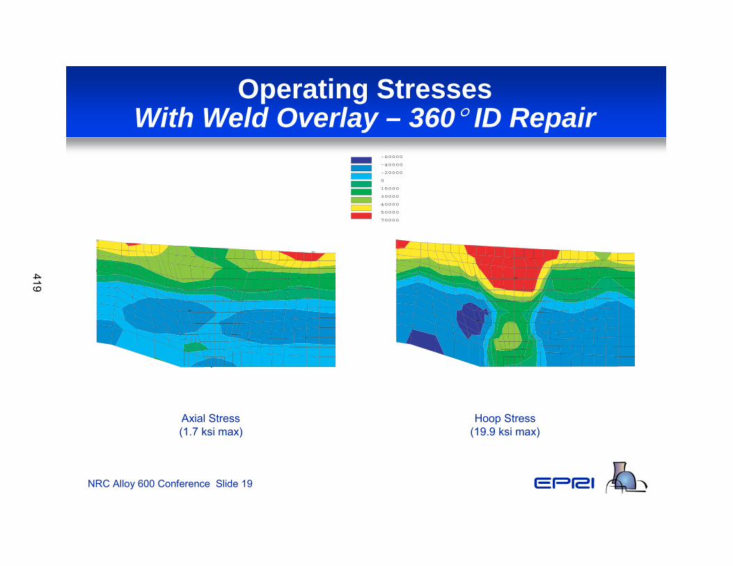
NRC Alloy 600 Conference Slide 19
Operating StressesWith Weld Overlay – 360° ID Repair
MN
MX
Axial Stress(1.7 ksi max)
Hoop Stress(19.9 ksi max)
MN
MX
-60000
-40000
-20000
0
15000
30000
40000
50000
70000
419
NRC Alloy 600 Conference Slide 20
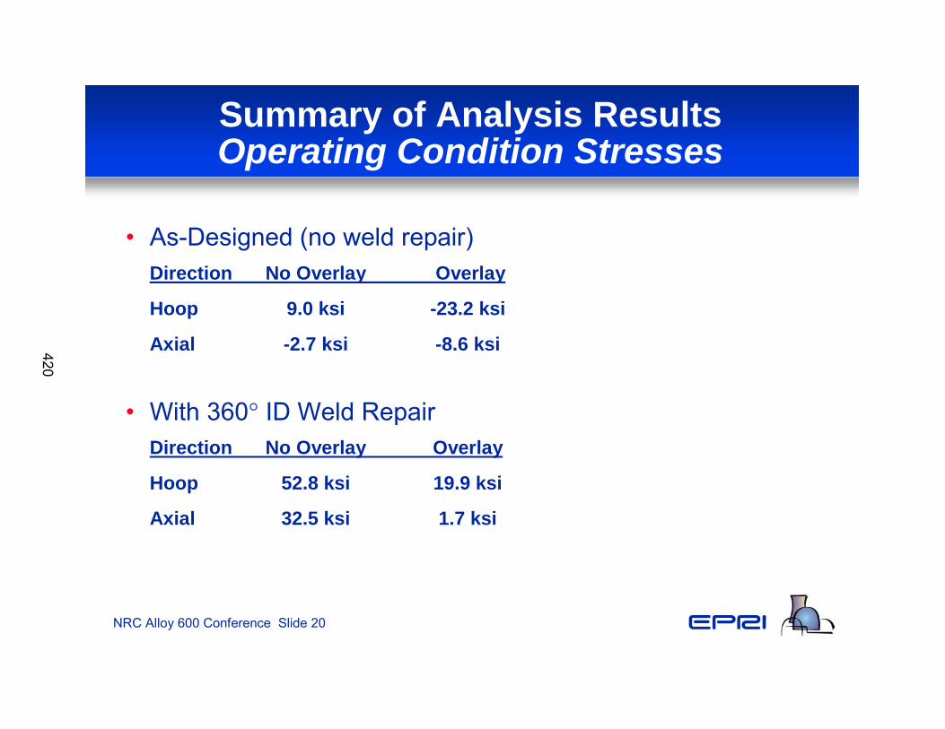
Summary of Analysis ResultsOperating Condition Stresses
• As-Designed (no weld repair)Direction No Overlay Overlay
Hoop 9.0 ksi -23.2 ksi
Axial -2.7 ksi -8.6 ksi
• With 360° ID Weld RepairDirection No Overlay Overlay
Hoop 52.8 ksi 19.9 ksi
Axial 32.5 ksi 1.7 ksi
420
NRC Alloy 600 Conference Slide 21
Conclusions
• Weld repairs to the nozzle ID after completing the through-wall weld produces high hoop and axial tensile stresses on the inside surface
• Partial-arc ID repairs also produce high hoop and axial stresses on the inside surface
• Weld overlay applied to the outside of the nozzle reduces the hoop and axial stresses on the nozzle ID surface– The weld overlay dimensions (thickness and length) can be
selected to produce the desired stress reduction over the area of potentially high ID stresses
– The axial length of the overlay deposits must be selected such that any increases in axial ID stress occurs in material that is not susceptible to PWSCC
421