Embed Size (px)
Citation preview
American Public Works Association i February 2017 Kansas City Metropolitan Chapter
DIVISION II CONSTRUCTION AND MATERIAL SPECIFICATIONS SEWERS
SECTION 2300 – INCIDENTAL CONSTRUCTION
APPROVED AND ADOPTED THIS 15th DAY OF FEBRUARY, 2017
KANSAS CITY METROPOLITAN CHAPTER OF THE AMERICAN PUBLIC WORKS ASSOCIATION
TABLE OF CONTENTS
2301 STANDARD SIDEWALKS, SIDEWALK RAMPS, DRIVEWAYS, AND BICYCLE /PEDESTRIAN PATHS ......... 1 2301.1 Scope ............................................................................................................................................................. 1 2301.2 Referenced Standards ................................................................................................................................... 1 2301.3 Materials ......................................................................................................................................................... 2 2301.4 Construction ................................................................................................................................................... 3 2301.5 Method of Measurement ................................................................................................................................ 6 2301.6 Basis of Payment ........................................................................................................................................... 6
SECTION 2302 ASPHALT SIDEWALKS, DRIVEWAYS, AND BICYCLE/PEDESTRIAN PATHS................................. 7 2302.1 Scope ............................................................................................................................................................. 7 2302.2 Asphalt Sidewalks .......................................................................................................................................... 7 2302.3 Asphalt Driveways .......................................................................................................................................... 7 2302.4 Asphalt Bicycle/Pedestrian Paths ................................................................................................................... 7 2302.5 Method of Measurement ................................................................................................................................ 7 2302.6 Basis of Payment ........................................................................................................................................... 7
SECTION 2303 ROCK BLANKET................................................................................................................................... 8 2303.1 Scope ............................................................................................................................................................. 8 2303.2 Materials ......................................................................................................................................................... 8 2303.3 Construction ................................................................................................................................................... 8 2303.4 Method of Measurement ................................................................................................................................ 8 2303.5 Basis of Payment ........................................................................................................................................... 8
SECTION 2304 CONCRETE PAVER STONES (FOR MEDIAN TREATMENT) ............................................................. 9 2304.1 Scope ............................................................................................................................................................. 9 2304.2 Referenced Standards ................................................................................................................................... 9 2304.3 Materials ......................................................................................................................................................... 9 2304.4 Construction ................................................................................................................................................. 10 2304.5 Method of Measurement .............................................................................................................................. 11 2304.6 Basis of Payment ......................................................................................................................................... 11
SECTION 2305 MAINTENANCE OF TRAFFIC ............................................................................................................ 11 2305.1 Scope ........................................................................................................................................................... 12 2305.2 Referenced Standards ................................................................................................................................. 12 2305.3 General ........................................................................................................................................................ 12 2305.4 Traffic Maintenance and Warning Devices ................................................................................................... 12 2305.5 Pedestrian Traffic Control ............................................................................................................................. 12 2305.6 Flashers and Other Traffic Control Devices ................................................................................................. 13 2305.7 Method of Measurement .............................................................................................................................. 13
American Public Works Association ii February 2017 Kansas City Metropolitan Chapter
2305.8 Basis of Payment ......................................................................................................................................... 13
SECTION 2306 PAVEMENT MARKINGS ..................................................................................................................... 13 2306.1 Scope ........................................................................................................................................................... 13 2306.2 Referenced Standards ................................................................................................................................. 13 2306.3 General ........................................................................................................................................................ 15 2306.4 Striping Applicability Chart ........................................................................................................................... 15 2306.5 Symbol Applicability Charts .......................................................................................................................... 15 2306.6 Prequalification ............................................................................................................................................. 16 2306.7 Materials ....................................................................................................................................................... 16 2306.8 Method of Installation ................................................................................................................................... 28 2306.9 Method of Removal ...................................................................................................................................... 35 2306.10 Performance Measures ................................................................................................................................ 35 2306.11 Method of Measurement .............................................................................................................................. 35 2306.12 Basis of Payment ......................................................................................................................................... 36
SECTION 2307 FENCING ............................................................................................................................................. 36 2307.1 Scope ........................................................................................................................................................... 36 2307.2 Referenced Standards ................................................................................................................................. 36 2307.3 Materials ....................................................................................................................................................... 36 2307.4 Construction ................................................................................................................................................. 37 2307.5 Method of Measurement .............................................................................................................................. 37 2307.6 Basis of Payment ......................................................................................................................................... 38
SECTION 2308 STEEL BEAM GUARDRAIL ................................................................................................................ 38 2308.1 Scope ........................................................................................................................................................... 38 2308.2 Referenced Standards ................................................................................................................................. 38 2308.3 Materials ....................................................................................................................................................... 38 2308.4 Construction ................................................................................................................................................. 38 2308.5 Method of Measurement .............................................................................................................................. 39 2308.6 Basis of Payment ......................................................................................................................................... 39
American Public Works Association 1 February 2017 Kansas City Metropolitan Chapter
2301 STANDARD SIDEWALKS, SIDEWALK RAMPS, DRIVEWAYS, AND BICYCLE /PEDESTRIAN PATHS
2301.1 Scope
This section governs the furnishing of all labor, materials and equipment for the construction or reconstruction of sidewalks, sidewalk ramps driveways, and bicycle/pedestrian paths as shown on the Plans and in accordance with the Standard Drawings, the specifications and the Special Provisions.
2301.2 Referenced Standards
The following standards are referenced directly in this section. The latest version of these standards shall be used. If conflicting standards are referenced, the more stringent standard shall apply. ADAAG – ADA Accessibility Guidelines Section 4.7 – Curb Ramps PROWAG - Public Rights-of-Way Accessibility Guidelines ASTM A 615 Standard Specification for Deformed and Plain Billet-Steel Bars for Concrete Reinforcement A 775 Standard Specification for Epoxy-Coated Steel Reinforcing Bars A 1064 Standard Specification for Carbon-Steel Wire and Welded Wire Reinforcement, Plain and Deformed, for
Concrete C 31 Standard Practice for Making and Curing Concrete Test Specimens in the Field C 39 Standard Test Method for Compressive Strength of Cylindrical Concrete Specimens C 143 Standard Test Method for Slump of Hydraulic-Cement Concrete C 172 Standard Practice for Sampling Freshly Mixed Concrete C 231 Standard Test Method for Air Content of Freshly Mixed Concrete by the Pressure Method C 309 Standard Specification for Liquid Membrane-Forming Compounds for Curing Concrete C 920 Standard Specification for Elastomeric Joint Sealants C 1064 Standard Test Method for Temperature of Freshly Mixed Hydraulic-Cement Concrete D 1751 Standard Specification for Preformed Expansion Joint Filler for Concrete Paving and Structural Construction
(Nonextruding and Resilient Bituminous Types) D 1752 Standard Specification for Preformed Sponge Rubber and Cork Expansion Joint Fillers for Concrete Paving
and Structural Construction D 2805 Standard Test Method for Hiding Power or Paints by Reflectometry D 7174 Standard Specification for Preformed Closed-Cell Ployolefin Expansion Joint Fillers for Concrete Paving and
Structural Construction AASHTO M 148 Standard Specification for Liquid Membrane-Forming Compounds for Curing Concrete MCIB Mid-West Concrete Industry Board Concrete Specifications - Concrete Pavement. The current editions of the "Bulletins" and Approved Sections of the "Standard Concrete Specifications"
issued by the Mid-West Concrete Industry Board, Inc. (MCIB) are made a part hereof by reference. However, when the provisions of this Specification differ from the provisions of such "Bulletins" and "Sections" the provisions of this Specification shall govern. Reference December 2000 Specifications if most recent version does not contain specified mix designs.

American Public Works Association 2 February 2017 Kansas City Metropolitan Chapter
KCMMB Kansas City Metro Materials Board Specifications Kansas Department of Transportation Standard Specifications for State Road and Bridge Construction, 2015 Edition Missouri Highways and Transportation Commission Missouri Standard Specifications for Highway Construction, 2011 Edition
2301.3 Materials A. Concrete: Concrete shall conform to referenced specifications as called out in the Contract Documents. If no
direct reference to concrete specifications is included in the Contract Documents, concrete shall meet KCMMB specifications.
1. If KCMMB concrete is specified, an approved KCMMB concrete mix shall be required.
2. If MCIB concrete is specified, concrete shall comply with MCIB Section entitled “Concrete Pavement”.
3. If KDOT specifications are referenced for concrete, provide material in compliance with the latest
version of KDOT specifications. Approval of component materials will be based on submittal of certifications from supplier. Aggregates shall meet the quality requirements specified by KDOT. Engineer reserves the right to perform testing of components to verify compliance.
4. If MoDOT specifications are referenced, provide material in compliance with the latest version of MoDOT specifications. Approval of component materials will be based on submittal of certifications from supplier. Aggregates shall meet the quality requirements specified by MoDOT. Engineer reserves the right to perform testing of components to verify compliance.
5. Proposed concrete mix designs for use on the project shall be submitted to Engineer for approval at least two (2) weeks in advance of anticipated use. Mix design shall be approved prior to use of that mix.
6. Field testing of concrete shall be at the Contractor’s expense and performed by an ACI certified materials testing firm acceptable to the Owner. Unless otherwise specified, the following tests shall be performed once for every 50 cuyd of concrete placed:
a. Sampling of fresh concrete per ASTM C 172 b. Slump per ASTM C 143 c. Air Content per ASTM C 231 d. Temperature per ASTM C 1064 e. Cylinders cast per ASTM C 31 and tested per ASTM C 39. Four cylinders shall be cast with
one tested at 7 days, 2 tested at 28 days and one held in reserve. B. Reinforcement: Reinforcement is not required unless shown on the Plans, Standard Drawings or in the Special
Provisions. If specified to be used, reinforcement shall meet the following requirements: 1. Bars: Non-epoxy coated bars shall conform to ASTM A 615. Epoxy coated bars shall conform to
ASTM A 775.

American Public Works Association 3 February 2017 Kansas City Metropolitan Chapter
2. Welded Steel Wire: Welded steel wire fabric shall conform to ASTM A 1064.
3. Supporting Elements: Representative samples of supporting elements shall be submitted and approved by the Engineer prior to their use in the project.
4. Fibers: When specified in the Contract Documents, fibers shall be incorporated into the concrete at the
rate recommended by the manufacturer but no less than a minimum of 3 pounds per cubic yard of concrete for macro fibers and 1 pound per cubic yard of concrete for micro fibers. Fibers shall meet the requirements of KDOT Standard Specifications for State Road and Bridge Construction, 2015 Edition, Section 1722.2. Micro fibers are used to control plastic shrinkage cracks in concrete while macro fibers control cracking in hardened concrete and are often used as a substitute for traditional crack control steel reinforcing bars or mesh. In addition, macro fibers add toughness, and impact and fatigue resistance to hardened concrete.
C. Isolation Joint: Isolation joints shall be formed by a one piece, 1/2-inch thick non–extruding preformed joint filler
cut to the configuration of the abutting section. The filler material shall be full depth, and shall conform to ASTM D 1751, D 1752, or D 7174. ASTM D 1752 material shall be used against curved surfaces, around utility boxes or poles, or against other irregular surfaces, and may be used for all other applications.
D. Joint sealer shall meet the requirements of Section 2208.3 or may be an approved one-component, moisture-
curing, non-priming, gun-grade, elastomeric polyurethane joint sealant that meets the requirements of ASTM C 920, Type S, Grade NS, Class 25, Use NT and M.
E. Curing Membrane: All material to be used or employed in curing Portland Cement Concrete must be approved
by the Engineer prior to its use. It shall be of the liquid membrane type and shall conform to ASTM C 309, Type II, Class A or B or AASHTO M 148, Type 2, white pigmented.
2301.4 Construction
The sidewalks, sidewalk ramps, driveways or bicycle/pedestrian paths shall be constructed or reconstructed to the configuration, and to the lines and grades shown on the Plans. Generally sidewalks, sidewalk ramps, driveways, and bicycle/pedestrian paths should be constructed after the curbing. Sidewalk ramp construction shall comply fully with all requirements for sidewalks in this section and shall comply with the requirements of ADAAG Section 4.7 and the most current federal guidelines governing sidewalk ramps (i.e. PROWAG). A. Removal: Existing sidewalks, sidewalk ramps, driveways, or bicycle/pedestrian paths shall be totally removed to
the nearest contraction or isolation joint, unless otherwise specified by the Engineer. The section shall be sawed full depth.
B. Grading, Subgrade Preparation and Base Course: All excavation, embankment, subgrade stabilization or
aggregate base course required shall be as defined in Sections 2100 “Grading and Site Preparation”, 2201 "Subgrade Preparation", 2202 “Subgrade Stabilization”, and 2203 “Aggregate Base Course”, except as follows:
1. Unless otherwise specified on the Plans, Standard Drawings or Special Provisions, the subgrade shall
be compacted until no further consolidation of the material occurs using compaction methods approved by the Engineer. The Engineer will visually determine the acceptance of the subgrade. Satisfactory moisture content shall be achieved to provide sufficient compaction of material as approved by the Engineer.

American Public Works Association 4 February 2017 Kansas City Metropolitan Chapter
If during reconstruction operations additional fill material is needed beneath sidewalks or driveways it shall be untreated compacted aggregate conforming to Section 2203.3.A, placed in conformance with Section 2203.4.A.
C. Forms: All forms shall be in good condition, clean, and free from imperfections. Each form shall not vary more
than 1/4 inch in horizontal or vertical alignment for each 10 feet in length.
1. Material and Size: Forms shall be made of metal unless otherwise approved by the Engineer and shall have a height equal to or greater than the depth of the sidewalk, driveway, or bicycle/pedestrian path section. Wood forms may be substituted when approved by Engineer and if they are free from warp with sufficient strength for the intended application.
2. Strength: Forms shall be of such cross–section and strength, and so secured as to resist the pressure
of the concrete when struck off, vibrated, and finished, and the impact and vibration of any equipment which they may support.
3. Installation: The forms shall be set true to line and grade, supported through their length and joined
neatly in such a manner that the joints are free from movement in any direction.
4. Preparation: Forms shall be cleaned and lubricated prior to each use and shall be so designed to permit their removal without damage to the new concrete.
D. Slip–form Machine: A slip–form machine may be used in lieu of forms. The machine must be equipped with
mechanical internal vibrators and be capable of placing concrete to the correct cross section, line and grade within the allowable tolerances.
E. Grades and Slopes: The grade and slope along the length of the walk shall conform to the most current version
of PROWAG. Unless shown otherwise on the Plans or directed by the Engineer, the cross slope shall be toward the street. The sidewalk cross slope shall be carried through driveways.
F. Joints: Unless directed by the Engineer the joints shall be formed at right angles to the alignment of the
sidewalk, driveway, or bicycle/pedestrian path and to the configuration specified by the Plans or Standard Drawings.
1. Joint Patterns
a. Sidewalk surfaces shall be marked with a transverse joint spaced at a distance equal to the
width of the sidewalk. Sidewalks greater than 6 feet in width shall be divided by longitudinal joints spaced not less than 30 inches nor more than 60 inches with transverse joints spaced to form a square pattern. Edger tool marks shall remain showing unless the sidewalk is slip–formed and subsequently sawed. Curb joints should align with sidewalk joints where they abut.
b. Concrete driveways and bicycle/pedestrian paths shall have a maximum slab dimension no greater than 10 feet, although widths no more than 24 times the slab thickness will be permitted to match existing joint patterns.
2. Isolation joints: Isolation joints shall be placed at locations shown on the Plans and Standard Drawings
or as directed by the Engineer.
a. General: The preformed isolation joint material shall be left 1/2-inch below the surface, or a suitable tear strip will be provided to allow for the application of the joint sealer.

American Public Works Association 5 February 2017 Kansas City Metropolitan Chapter
b. Stability: Isolation joints shall be secured in a manner so they will not be disturbed by depositing and consolidating the concrete.
c. Edging: The newly poured edges of these joints shall be rounded with an edging tool of ¼ inch radius.
d. Spacing: Isolation joints shall be placed at spacing indicated on the Plans or Standard Drawings. Spacing should not exceed 100’ from center to center.
3. Contraction joints: Contraction joints shall be 1-inch deep by 1/8-inch wide with 1/4-inch radii rounded
edges.
a. Edging: Edger marks shall remain showing unless the sidewalk, driveway or bicycle/pedestrian path is slip formed and subsequently sawed.
b. Slip forming: Contraction joints may be sawed 1/8-inch wide by 1/3rd the thickness of the slab.
c. Joint Sealer: Joint sealer is not required, unless otherwise specified in the Plans, Standard Drawings or Special Provisions.
G. Concrete Work: Concrete shall be furnished in quantities required for immediate use and shall be placed in
accordance with the requirements of the applicable specification as stipulated in Section 2208.3.A.
1. Concrete Placement: Deposit and consolidate concrete as close to the final position as possible, beginning at one corner of the forms. Perform necessary hand spreading with shovels or come–alongs, not with rakes or vibrators. All concrete shall be well vibrated unless approved otherwise by the Engineer. Do not walk in the fresh concrete with boots or shoes coated with earth or foreign substances. When concrete is placed on a sloped surface, begin concrete placement at the lowest area.
Limitations for time of placement and other items not specifically covered by this specification shall be in accordance with the most recent Standard Specifications of the State Department of Transportation for the state the work is being performed in. The Engineer may extend placement time limitations based on field conditions and concrete consistency and workability.
2. Finishing
a. Strike off the concrete with a vibratory screed or a hand strike–off method when adequate
consolidation is attained. Immediately after strike–off, the concrete may be bull-floated to remove any high or low spots. Minimize the use of the bull-float.
b. Do not finish concrete with water standing on the surface. All edges of the slab shall be carefully finished with a 1/4-inch radius edger.
c. After finishing, the surface of the concrete shall be broomed with a fine clean broom to provide an antiskid surface, and the edges and joints retooled unless slip-formed.
d. In all cases the finished sidewalk, driveway, or bicycle/pedestrian path shall have a true surface, free from sags, twists, or warps, and shall have a uniform color and appearance.
3. Curing: As soon as practical after the concrete is finished it shall be cured with an approved liquid
curing membrane applied according to manufacturer’s directions.
a. If forms are removed within a period of 72 hours of placement those formed surfaces shall also be cured.
b. Wet burlap, cotton mats, waterproof paper, polyethylene sheeting or earth backfill shall not be acceptable as curing methods.

American Public Works Association 6 February 2017 Kansas City Metropolitan Chapter
4. Protection: The Contractor shall protect the concrete work against damage or defacement of any kind
until it has been accepted by the Engineer. Concrete which is damaged or defaced shall be removed and replaced or repaired to the satisfaction of the Engineer, at the expense of the Contractor.
5. Temperature Limitations: Concrete shall be placed in accordance with requirements of the state DOT
specifications for the state where the work is being performed. H. Backfill: A minimum of 24 hours shall elapse before forms are removed and 5 days shall elapse or the concrete
must have attained 75% of its 28 day compressive strength before pavement is backfilled unless otherwise approved by the Engineer.
I. Backfill shall be accomplished in accordance with Sections 2100 and 2201 entitled "Grading and Site
Preparation" and "Subgrade Preparation". J. The Contractor shall be responsible for the repair of any street pavement damaged by the construction to the
satisfaction of the Engineer. K. Joint Sealing and Clean–Up: All isolation joints shall be sealed with an approved joint sealer meeting the
requirements of Section 2301.3.D applied in accordance with Section 2208.4 and the manufacturer’s directions within 7 days of the placement of the concrete and prior to the opening of the pavement to traffic.
L. The Contractor shall be responsible for the removal of excess dirt, rock, broken concrete, splatters and
overspray from the construction area within 10 days unless otherwise directed by the Engineer. M. Surface Tolerances: Sidewalks, driveways, and bicycle/pedestrian paths shall have a surface tolerance of 1/4
inch in 10 feet when checked with a 10 foot straightedge. Vertical deflections at sidewalk joints shall not exceed 1/4-inch.
N. Detectable Warnings: Detectable warnings are required standardized surface features built in or applied to
walking surfaces on sidewalks or ramps to warn visually impaired people of hazards on a circulation path. Those hazards include, but are not limited to interfaces between sidewalks and areas where moving vehicles may be present. Detectable warnings shall be in accordance with PROWAG Section R305.
2301.5 Method of Measurement A. Sidewalks: Sidewalks will be measured per square foot or tenth part thereof. B. Sidewalk Ramps: Sidewalk ramps including detectable warning will be measured by one of the following:
1. Per square foot or tenth part thereof. Street curbing adjoining sidewalk ramps will be measured in accordance with Section 2209.5 and paid for separately.
2. Per each.
C. Driveways: Driveways will be measured per square foot or tenth part thereof. D. Bicycle/Pedestrian Paths: Bicycle/Pedestrian paths will be measured per square foot or tenth part thereof.
2301.6 Basis of Payment

American Public Works Association 7 February 2017 Kansas City Metropolitan Chapter
All items in this section will be paid for by the Contract unit bid price.
SECTION 2302 ASPHALT SIDEWALKS, DRIVEWAYS, AND BICYCLE/PEDESTRIAN PATHS
2302.1 Scope
This section governs the furnishing of all labor, materials and equipment for the construction or reconstruction of asphalt sidewalks, driveways, and bicycle/pedestrian paths as shown on the Plans and in accordance with the Standard Drawings, the specifications and the Special Provisions.
2302.2 Asphalt Sidewalks
Asphalt shall not be used in the construction of any approved permanent sidewalk. Asphalt may be used as material for temporary sidewalks if approved in advance by the Engineer.
2302.3 Asphalt Driveways
Asphalt driveways may be constructed with prior approval of the Engineer in accordance with the provisions of Section 2205 "Asphalt Paving" and Section 2209 "Curbing" as applicable.
2302.4 Asphalt Bicycle/Pedestrian Paths
Asphalt bicycle/pedestrian paths shall be constructed in accordance with the provisions of Section 2205 “Asphalt Paving” and in accordance with the applicable provisions of Section 2302.3.
2302.5 Method of Measurement A. Asphalt Sidewalks: Asphalt Sidewalks will be measured by one of the following:
1. Per ton or tenth part thereof.
2. Per square foot or tenth part thereof. B. Asphalt Driveways: Asphalt Driveways will be measured by one of the following:
1. Per ton or tenth part thereof.
2. Per square foot or tenth part thereof.
C. Asphalt Bicycle Pedestrian Paths: Asphalt Bicycle/Pedestrian paths will be measured by one of the following:
1. Per ton or tenth part thereof.
2. Per square foot or tenth part thereof.
2302.6 Basis of Payment
American Public Works Association 8 February 2017 Kansas City Metropolitan Chapter
All items in this section will be paid for at the Contract unit bid price.
SECTION 2303 ROCK BLANKET 2303.1 Scope
This section governs the furnishing of all labor, materials and equipment for the construction of a protecting blanket of rock or broken concrete on slopes, channel bank or stream banks as shown on the Plans and in accordance with the Standard Drawings, the specifications and the Special Provisions.
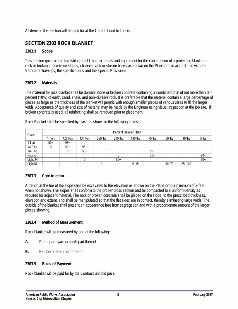
2303.2 Materials
The material for rock blanket shall be durable stone or broken concrete containing a combined total of not more than ten percent (10%) of earth, sand, shale, and non–durable rock. It is preferable that the material contain a large percentage of pieces as large as the thickness of the blanket will permit, with enough smaller pieces of various sizes to fill the larger voids. Acceptance of quality and size of material may be made by the Engineer using visual inspection at the job site. If broken concrete is used, all reinforcing shall be removed prior to placement.
Rock Blanket shall be specified by class as shown in the following tables:
Class Percent Heavier Than
1 Ton 1/2 Ton 1/4 Ton 250 lbs 200 lbs 180 lbs 75 lbs 60 lbs 10 lbs 5 lbs 1 Ton 50+ 95+ 1/2 Ton 0 50+ 95+ 1/4 Ton 0 50+ 90+ Facing 0 50+ 90+ Light 24 0 50+ 90+ Light18 0 5–15 50–70 85–100
2303.3 Construction
A trench at the toe of the slope shall be excavated to the elevation as shown on the Plans or to a minimum of 2-feet when not shown. The slopes shall conform to the proper cross section and be compacted to a uniform density as required for adjacent material. The rock or broken concrete shall be placed on the slope, to the prescribed thickness, elevation and extent, and shall be manipulated so that the flat sides are in contact, thereby eliminating large voids. The outside of the blanket shall present an appearance free from segregation and with a proportionate amount of the larger pieces showing.
2303.4 Method of Measurement
Rock blanket will be measured by one of the following: A. Per square yard or tenth part thereof. B. Per ton or tenth part thereof.
2303.5 Basis of Payment
Rock blanket will be paid for by the Contract unit bid price.
American Public Works Association 9 February 2017 Kansas City Metropolitan Chapter
SECTION 2304 CONCRETE PAVER STONES (FOR MEDIAN TREATMENT) 2304.1 Scope
This section governs the furnishing of all labor, equipment and tools and for the performance of all work necessary to install concrete paver stones as shown on the Plans and in accordance with the Standard Drawings, the specifications and the Special Provisions.
2304.2 Referenced Standards
The following standards are referenced directly in this section. The latest version of these standards shall be used. If conflicting standards are referenced, the more stringent standard shall apply. ASTM C 67 Standard Test Methods for Sampling and Testing Brick and Structural Clay Tile C 140 Standard Test Methods for Sampling and Testing Concrete Masonry Units and Related Units C 418 Standard Test Method for Abrasion Resistance of Concrete by Sandblasting C 936 Standard Specification for Solid Concrete Interlocking Paving Units MCIB Mid-West Concrete Industry Board Concrete Specifications - Concrete Pavement
The current editions of the "Bulletins" and Approved Sections of the "Standard Concrete Specifications" issued by the Mid-West Concrete Industry Board, Inc. (MCIB) are made a part hereof by reference. However, when the provisions of this Specification differ from the provisions of such "Bulletins" and "Sections" the provisions of this Specification shall govern. Reference December 2000 Specifications if most recent version does not contain specified mix designs.
KCMMB Kansas City Metro Materials Board Specifications
2304.3 Materials A. Interlocking Concrete Paver Stones (ASTM C 936)
1. Paver stones shall be cobblestone style consisting of full stones, 4-5/8" x 7" x 2-3/8"; two thirds stones,
4-5/8" x 4-5/8" x 2 3/8"; and one third stones, 4-5/8" x 2-5/16" x 2-3/8". The mix of stones sizes shall be approximately 28% full size, 57% two thirds size and 15% one third size.
2. Cementitous Materials: Materials shall conform to the ASTM, AASHTO and other referenced
specifications as required by mix design specifications (MCIB or KCMMB).
3. Aggregates: Aggregates shall conform to the ASTM, AASHTO and other referenced specifications as required by mix design specifications (MCIB or KCMMB).
4. Other Constituents: Air–entraining agents, coloring pigments, integral water repellents, finely ground
silica, etc. shall conform to ASTM standards where applicable, or shall be previously established as suitable for use in concrete.
5. Physical Requirements: The Contractor shall provide a certification showing compliance with the
following requirements. The Engineer reserves the right to sample and test materials as deemed necessary.
American Public Works Association 10 February 2017 Kansas City Metropolitan Chapter
a. Compressive Strength: At the time of delivery to the work site, the average compressive strength shall be not less than 8,000 psi with no individual unit strength less than 7,200 psi, with testing procedures in accordance with ASTM C 140.
b. Absorption: The average absorption shall not be greater than 5% with no individual unit absorption greater than 7%.
c. Durability: The manufacturer shall satisfy the Engineer either by proven field performance or the laboratory freeze–thaw test that the paving units have adequate durability. i. Proven Field Performance: Satisfactory field performance is indicated when units
similar in composition, and made with the same manufacturing processes as those to be supplied to the Contractor, do not exhibit objectionable deterioration after at least three years. The units used as the basis for proven field performance shall have been exposed to the same environmental factors as is contemplated for the units supplied to the Contractor.
ii. Freeze–Thaw Test: When tested in accordance with Section 8 of ASTM C 67, specimens shall have no breakage and not greater than 1.0% loss in dry weight of any individual unit when subjected to 50 freeze–thaw cycles. This test shall be conducted not more than 12 months prior to delivery of units.
d. Abrasion Resistance: When tested by sandblasting in accordance with ASTM C 418, specimens shall not have greater volume loss than 0.3 cubic inches per square inch. The average thickness loss shall not exceed 1/8-inch.
e. Permissible Variations in Dimensions: Length or width of units shall not differ by more than 1/16-inch from approved samples. Heights of units shall not differ by more than 1/8-inch from the specified standard.
f. Visual Inspection: All units shall be sound and free of defects that would interfere with the proper placing of unit or impair the strength or permanence of the construction. Minor cracks incidental to the usual methods of manufacturer, or minor chipping resulting from customary methods of handling in shipment and delivery, shall not be deemed grounds for rejection.
6. Sampling and Testing: The Engineer or his authorized representative shall be accorded proper
facilities to inspect and sample the units at the place of manufacture from the lot ready for delivery. Sampling and testing of units shall be in accordance with ASTM C 140 except as required.
7. Rejection: In case the shipment fails to conform to the specified requirements, the manufacturer may
sort it, and new test units shall be selected at random by the Engineer from the retained lot and tested at the expense of the manufacturer. In case the second set of test units fails to conform to specified requirements, the entire lot shall be rejected.
8. Expense of Tests: The expense of inspection and testing shall be borne by the Engineer except as
specified otherwise above. B. Base Course Concrete: Base course concrete shall conform to the requirements of MCIB Mix No. WA610–1–4
or an approved KCMMB 4K mix. C. Sand for Laying Course: The sand for the laying course shall be well graded, clean, washed, sharp sand with
100% passing a 3/8" sieve size and a maximum of 3% passing a No. 200 sieve size. This is commonly known as manufactured concrete sand, limestone screening, or similar. Mason Sand will not be permitted.
2304.4 Construction A. Product Handling: Paver stones shall be delivered and unloaded at jobsite on pallets and bound in such a
American Public Works Association 11 February 2017 Kansas City Metropolitan Chapter
manner that no damage occurs to the product during handling, hauling and unloading. B. Edge Restraint: All edges of the installed paver stone shall be restrained by the concrete curb, concrete
sidewalk, or another suitable method for preventing the movement of the edge stones. C. Concrete Base Course: A concrete base course shall be constructed in accordance with the requirements of
Section 2301. The base course shall be shaped to the grade and cross section as shown on the plans with an allowable tolerance of 1/4-inch. The base course shall be 4-inches thick, and should be graded to allow a 1-inch thick sand course between the base and the paving stones, unless shown otherwise on the Plans.
Payment for concrete base course shall be subsidiary to other bid items. The finished base course must be approved by the Engineer before the placement of the sand laying course. The uncompacted sand laying course shall be spread evenly over the area to be paved and then screened to a level that will produce 1-inch thickness when the paver stones have been placed and vibrated. Once screened and leveled to the desired elevation, the sand laying course shall not be disturbed in any way.
D. Placing Paver Stones: The paver stones shall be installed in rows perpendicular to the major axis of the median
being paved. Within each row the stone sizes shall be randomly mixed so that joints between stones are not normally aligned with joints between stones in adjacent rows. No joints shall be aligned for more than three consecutive rows. The paver stones shall be laid in such a manner that the desired pattern is maintained and the joints between the stones are as tight as possible. For maximum interlock it is recommended that joints between stones do not exceed 1/8 inch. String lines should be used to hold all pattern lines true.
The gaps at the edge of the paver surface shall be filled with standard edge stones or with stones cut to fit. Cutting shall be accomplished to leave a clean edge to the traffic surface using a double–headed breaker or a masonry saw. However, when cutting precision designed areas, a masonry saw is recommended. Whenever possible, no cuts should result with a paver less than 1/3 of original dimension.
Paver stones shall be vibrated to their final level in the sand laying course by two or three passes of a vibrating compactor capable of 3,000 to 5,000 pounds compaction force with the surface clean and joints open. After vibration, clean concrete sand containing at least 30% of 1/8-inch particles shall be spread over the paver stone surface, allowed to dry, and vibrated into the joints with additional passes of the plate vibrator so as to completely fill the joints.
Surplus material shall then be swept from the surface. Upon completion of work covered in this Section, the Contractor shall clean up all work areas by removing all debris, surplus material and equipment from the site.
After final vibrating, the surface shall be true to grade and shall not vary by more than 1/4-inch when tested with a 10 foot straight edge at any location on the surface.
2304.5 Method of Measurement
Concrete Paver Stones will be measured by the square foot or tenth part thereof.
2304.6 Basis of Payment
Concrete Paver Stones will be paid for by the Contract unit bid price.
SECTION 2305 MAINTENANCE OF TRAFFIC
American Public Works Association 12 February 2017 Kansas City Metropolitan Chapter
2305.1 Scope
This section governs the furnishing of all labor, equipment and tools and for the performance of all work necessary to provide Maintenance of Traffic as specified herein, as shown on the Plans and in accordance with the Standard Drawings, the specifications and the Special Provisions.
2305.2 Referenced Standards
The following standards are referenced directly in this section. The latest version of these standards shall be used. If conflicting standards are referenced, the more stringent standard shall apply. ATSSA Quality Standards for Work Zone Traffic Control Devices Manual of Uniform Traffic Control Devices, Part VI (MUTCD)
2305.3 General
The Contractor is required to maintain access for pedestrians and vehicles to all properties served by the streets and sidewalks impacted by the construction.
2305.4 Traffic Maintenance and Warning Devices
A. The Contractor will be responsible for arranging for installation of the necessary traffic control devices (with the
exception of the barricades and other channelizing devices) a minimum of 48 hours prior to beginning the project so that inspection can be conducted by the Engineer.
Traffic maintenance devices including barricades, flashing lights, flaggers and other traffic control devices shall be in conformance with "Part VI of the Manual on Uniform Traffic Control Devices" latest edition.
B. Device Maintenance: The Contractor's representative will make daily inspections of the traffic control devices
installed and maintain records of any maintenance required and the date on which it was completed. These records will be maintained for the duration of the project and be incorporated as part of the final records. It shall be the Contractor's responsibility to maintain all traffic control devices in proper working condition and placement at all times. The Contractor shall promptly correct any deficiencies in traffic control.
C. Traffic Control Plan Revisions: Engineer reserves the right to make adjustments or revisions in traffic handling
requirements that may become necessary after construction has started. These changes will be determined on the basis of periodic inspections throughout the duration of the project. Notice of such change will be transmitted to the Contractor and it will be his responsibility to make the necessary changes as soon as practicable after receipt of the notification.
2305.5 Pedestrian Traffic Control A. Devices: All traffic control along pedestrian routes (sidewalks) shall meet the requirements of sections of the
latest version of the MUTCD. Particular attention should be paid to 6D.01and 6D.02 for pedestrian safety. B. Pedestrian Route Closures: Pedestrian routes shall not be closed unless approved by the Engineer. If a
pedestrian route must be temporarily closed, an alternate accessible route must be maintained.
American Public Works Association 13 February 2017 Kansas City Metropolitan Chapter
C. Pedestrian Access: Accessible pedestrian access to all buildings served by the sidewalk must be maintained at all times during the project.
D. Pedestrian Routes Protection: Existing pedestrian routes and alternate accessible routes shall be protected
from construction activities at all times. This protection may include, but is not limited to, railings, fences, barricades, and covered walkways.
2305.6 Flashers and Other Traffic Control Devices
All traffic control devices shall be maintained in acceptable condition as defined by the latest ATSSA “Quality Standards for Work Zone Traffic Control Devices.” Devices in unacceptable or marginal condition as determined above shall be removed from the job site and replaced with devices in acceptable condition.
2305.7 Method of Measurement
Maintenance of Traffic will be measured as specified by the Contract Documents. Measurements shall be per each device per day listed as identified in the Plans and as adjusted by the Engineer during construction. The device must be set for at least one–half of a calendar day for it to be measured for payment. Relocation of devices required by project phasing shown on the Plans or proposed by the Contractor shall be subsidiary to the line item.
2305.8 Basis of Payment
Maintenance of Traffic will be paid for by one of the following: A. Contract unit bid price. B. Contract lump sum bid price.
SECTION 2306 PAVEMENT MARKINGS
2306.1 Scope
This section governs the furnishing of labor, equipment, and materials and for the performance of work necessary to furnish and install white and yellow permanent or temporary retro–reflectorized pavement marking materials as shown on the Plans and in accordance with the Standard Drawings, the specifications and the Special Provisions.
2306.2 Referenced Standards
The following standards are referenced directly in this section. The latest version of these standards shall be used. ASTM C 321 Standard Test Method for Bond Strength of Chemical–Resistant Mortars C 501 Standard Test Method for Relative Resistance to Wear of Unglazed Ceramic Tile by the Tile Abraser D 36 Standard Test Method for Softening Point of Bitumen (Ring and Ball Apparatus) D 92 Standard Test Method for Flash and Fire Points by Cleveland Open Cup Tester D 93 Standard Test Methods for Flash Point by Pensky Martens Closed Tester D 256 Standard Test Method Methods for Determining the Izod Pendulum Impact Resistance of Plastic D 476 Standard Specification for Titanium Dioxide Pigments, Type II Rutile
American Public Works Association 14 February 2017 Kansas City Metropolitan Chapter
D 562 Standard Test Method for Consistency of Paints Using Stormer Viscosimeter D 570 Standard Test Method for Water Absorption of Plastics D 638 Standard Test Method for Tensile Properties of Plastics D 711 Standard Test Method for No–Pick–Up Time of Traffic Paint D 768 Standard Specification for Yellow Iron Oxide D 868 Standard Test Method for Evaluating Degree of Bleeding of Traffic Paint D 1152 Standard Specification for Methanol (Methyl Alcohol) D 1155 Standard Test Method for Roundness of Glass Spheres D 1199 Standard Specification for Calcium Carbonate Pigments D 1210 Standard Test Method for Fineness of Dispersion of Pigment–Vehicle Systems by Hegman–Type Gage D 1214 Standard Test Method for Sieve Analysis of Glass Spheres D 1475 Standard test Method for Density of Paint, Varnish, Lacquer, and Related Products D 2240 Standard Test Method for Rubber Property–Durometer Hardness D 2243 Standard Test Method for Freeze–Thaw Resistance of Waterborne Coatings D 2369 Standard Test Method for Volatile Content of Coatings D 2805 Standard Test Method for Hiding Power of Paints by Reflectometry D 3723 Standard Test Method for Pigment Content of Water Emulsion by Low Temperature Ashing D 3960 Standard Practice for Determining Volatile Organic Content (VOC) of Paints and Related Coatings D 4060 Standard Test Method for Abrasion Resistance of Organic Coatings by Taber Abraser D 4061 Standard Test Method for Retroreflectance of Horizontal Coating D 4366 Standard Test Methods for Hardness of Organic Coatings by Pendulum Damping Tests D 4796 Standard Test Method for Bond Strength of Thermoplastic Traffic Marking Material D 5420 Standard Test Method for Impact Resistance of Flat, Rigid Plastic Specimen by Means of a Striker Impacted
by a Falling Weight (Gardner Impact) E 70 Standard Test Method for pH of Aqueous Solutions With the Glass Electrode E 303 Standard Test Method for Measuring Surface Frictional Properties Using the British Pendulum Tester E 308 Standard Practice for Computing the Colors of Objects by Using the CIE System E 660 Standard Practice for Accelerated Polishing of Aggegrates or Pavement Surfaces Using a Small–Wheel,
Circular Track Polishing Machine E 1347 Standard Test Method for Color and Color–Difference Measurement by Tristimulus (Filter) Colorimetry E 1349 Standard Test Method for Reflectance Factor and Color by Spectophotometry Using Bidirectional Geometry AASHTO M 247 Standard Specification for Glass Beads Used in Pavement Markings M 249 Standard Specification for White and Yellow Reflective Thermoplastic Striping Material (Solid Form) T 250 Standard Method of Test for Thermoplastic Traffic Line Material Manual of Uniform Traffic Control Devices, latest Edition (MUTCD) ACI Federal Test Method Standard No. 141d, Method 4252 – Paint, Varnish, Lacquer and Related Materials; Methods of
Inspection, Sampling and Testing Federal Test Method Standard No. 141d, Method 6242 – Paint, Varnish, Lacquer and Related Materials; Methods of
Inspection, Sampling and Testing Federal Standard 595, Colors used in Government Procurement Federal Specification TT–P–115a – Paint, Traffic (Highway, White and Yellow) Federal Specification TT–P–1952B – Paint, Traffic and Airfield Marking, Water Emulsion Base “Standard Color Chips for Highway Signs” (US Bureau of Public Roads, Washington D.C.)
American Public Works Association 15 February 2017 Kansas City Metropolitan Chapter
KDOT Standard Specifications Section 2214.2.a(2)(d) Bond Strength National Board of Fire Underwriters of the National Fire Protection Association Standards
2306.3 General
The permanent pavement markings shall be installed immediately after the roadway surface is complete unless prior approval is received by the Engineer. The installation of the yellow markings (as required) is the first priority. If the permanent markings cannot be installed and thus the roadway would be unmarked overnight, temporary removable markings shall be installed and remain until the permanent markings can be installed. The contractor shall make every possible effort to remove the temporary pavement markings and install permanent pavement markings within 48 hours. Only under extreme circumstances and with the approval of the Engineer, will the duration of the temporary pavement markings be extended. Under no circumstance should the temporary pavement markings be in place for more than 2 weeks. If permanent markings cannot be installed within the specified time then semi–permanent markings shall be installed following the guidelines as set forth in the latest edition of the Manual on Uniform Traffic Control Devices (MUTCD) Part VI, Sections F6 and G6. The temporary removable markings shall be removed prior to installation of the permanent markings. In situations where markings conflict with the traffic routing, such as a lane closure or a lane diversion, conflicting markings shall be removed prior to application of the next set of markings.
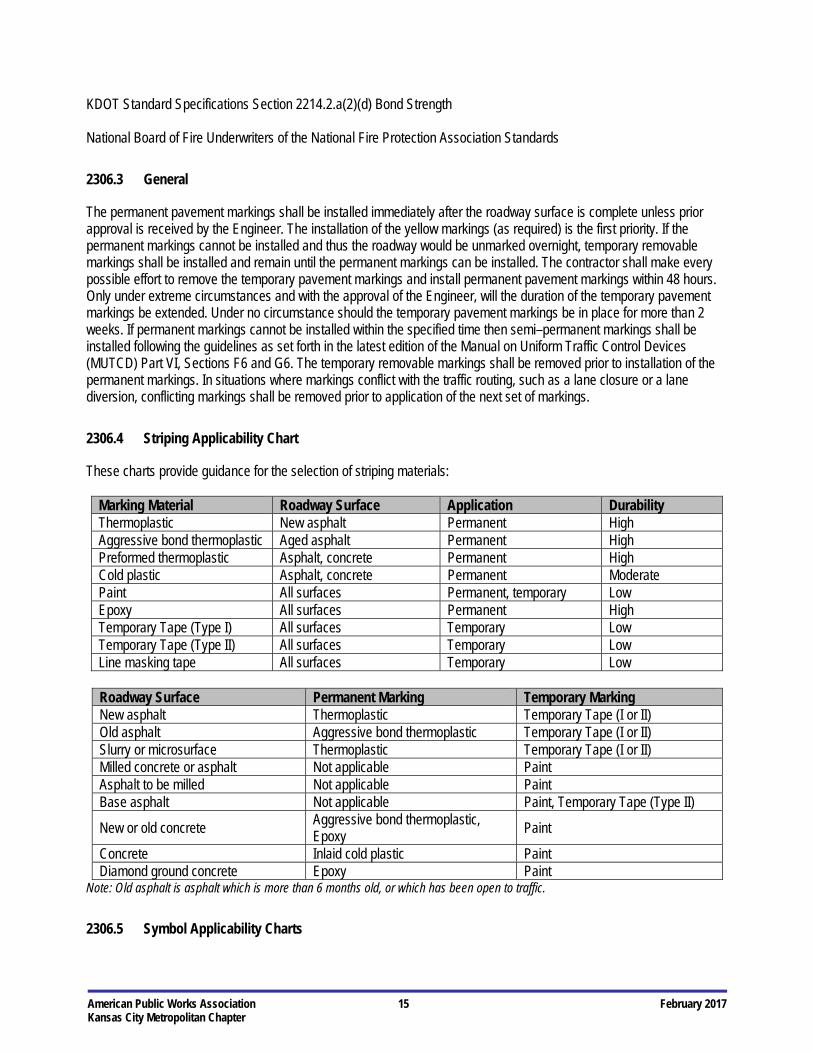
2306.4 Striping Applicability Chart
These charts provide guidance for the selection of striping materials:
Marking Material Roadway Surface Application Durability Thermoplastic New asphalt Permanent High Aggressive bond thermoplastic Aged asphalt Permanent High Preformed thermoplastic Asphalt, concrete Permanent High Cold plastic Asphalt, concrete Permanent Moderate Paint All surfaces Permanent, temporary Low Epoxy All surfaces Permanent High Temporary Tape (Type I) All surfaces Temporary Low Temporary Tape (Type II) All surfaces Temporary Low Line masking tape All surfaces Temporary Low
Roadway Surface Permanent Marking Temporary Marking New asphalt Thermoplastic Temporary Tape (I or II) Old asphalt Aggressive bond thermoplastic Temporary Tape (I or II) Slurry or microsurface Thermoplastic Temporary Tape (I or II) Milled concrete or asphalt Not applicable Paint Asphalt to be milled Not applicable Paint Base asphalt Not applicable Paint, Temporary Tape (Type II)
New or old concrete Aggressive bond thermoplastic, Epoxy
Paint
Concrete Inlaid cold plastic Paint Diamond ground concrete Epoxy Paint
Note: Old asphalt is asphalt which is more than 6 months old, or which has been open to traffic.
2306.5 Symbol Applicability Charts

American Public Works Association 16 February 2017 Kansas City Metropolitan Chapter
These charts provide guidance for the selection of text and non–text symbol materials:
Roadway Surface Text Symbols Temporary Text Symbols New asphalt Pre-formed thermoplastic Temporary Tape (I or II) Old asphalt Pre-formed thermoplastic Temporary Tape (I or II), paint Slurry or microsurface Pre-formed thermoplastic Temporary Tape (I or II), paint Milled concrete or asphalt Not applicable Paint Asphalt to be milled Not applicable Paint Base asphalt Not applicable Paint New or old concrete Inlaid cold plastic Temporary Tape (I or II) Concrete Inlaid cold plastic Temporary Tape (I or II) Diamond ground concrete Inlaid cold plastic Temporary Tape (I or II)
2306.6 Prequalification A. If the Owner has an established prequalification program, manufacturers interested in prequalifying material
under this specification shall submit to the Owner:
1. A sample of the material. Sample quantities are determined by the Owner. The submittal of a material sample may be waived by the Owner at their discretion.
2. Certifications by qualified testing laboratories that the material meets all required tests.
3. A list of existing installations.
B. The Owner may test submitted samples or materials as used for compliance with all requirements of this
specification. C. Products will remain on the prequalified list as long as the results of verification testing and/or field performance
are satisfactory. Any changes in formulation should be reported to the Owner for review and evaluation to determine if requalification is necessary.
D. No material shall be used unless the material has been prequalified or approved by the Engineer. E. A list of qualified materials by manufacturer may be maintained by the Owner.
2306.7 Materials A. Pre–Mix Glass Spheres: Pre–mix glass spheres shall be uncoated and conform to AASHTO M 247 Type 1. The
glass spheres used in the formulation shall be lustrous, free from film, scratches, and pits. The glass spheres shall also meet the following requirements:
1. Roundness: The roundness of the spheres shall be a minimum of 70% when tested in accordance with
ASTM D 1155.
2. Gradation: The gradation when tested in accordance with the method provided in ASTM D 1214 (by use of U.S. Standard Sieves) shall be:

American Public Works Association 17 February 2017 Kansas City Metropolitan Chapter
Size of Sieve Mass % Passing No. 18 80 – 100 No. 50 20 – 50 No. 80 0 – 10
3. Refractive Index: When tested by a liquid immersion method at 77° F, the refractive index of the
spheres shall be a minimum of 1.50.
B. Drop–On Glass Spheres: The spheres shall be manufactured from glass of a composition designed to be highly resistant to traffic wear and to the effects of weathering. The particles shall be spherical in shape, containing not more than thirty percent (30%) of irregularly shaped particles. They shall be essentially free of sharp angular particles, and particles showing milkiness or surface scoring or scratching. They shall meet the requirements of AASHTO M 247 Type 1.
1. Gradation: The gradation when tested in accordance with the method provided in ASTM D 1214 (by
use of U.S. Standard Sieves) shall be:
Size of Sieve % Passing (by Weight) No. 20 100 No. 30 80 – 100 No. 50 18 – 35 No. 80 0 – 10
No. 100 0 – 2
2. Refractive Index: When tested by a liquid immersion method at 77° F, the refractive index of the spheres shall be within the range of 1.50 to 1.60.
3. Moisture Proof Requirements: The spheres shall show no tendency to absorb moisture in storage and
shall remain free of clusters and hard lumps. The spheres shall flow freely from dispensing equipment at any time when surface and atmospheric conditions are satisfactory for application.
C. Thermoplastic Pavement Markings: This specification covers a white and yellow thermoplastic reflectorized
pavement marking material of a type that is applied to asphalt road surfaces in a molten state by mechanical means to receive a surface application of glass spheres, and which upon cooling to normal pavement temperature, produces an adherent reflectorized stripe of specified thickness and width and is capable of resisting deformation.
1. Characteristics: The material shall not exude fumes that are toxic, obnoxious or injurious to person or
property, when it is heated to the temperature range specified by the manufacturer for application. It shall remain stable when held for 4 hours at this temperature, or when subject to three reheatings after cooling to ambient temperature.
The temperature–viscosity characteristics of the plastic material shall remain constant throughout repeated reheatings, and shall show like characteristics from batch to batch. There shall be no obvious change in color of the material either as a result of repeated reheatings or from batch to batch.
The thermoplastic material shall easily extrude from the equipment to produce a cross–section of line 90 to 125 mil thick, which shall be continuous and uniform in shape, and have clear and sharp dimensions.
American Public Works Association 18 February 2017 Kansas City Metropolitan Chapter
2. Serviceability: The compound shall resist deterioration by contact with sodium chloride, calcium chloride or other chemicals used to prevent roadway ice, or because of the oil content of pavement materials or from oil droppings or other effects of traffic. The markings shall remain intact under normal traffic conditions at temperatures below 140° F.
3. Specific Gravity: The material’s specific gravity shall not be less than 1.8 nor exceed 2.3 referred to
water at 77° F when determined by a water displacement method at 77° F.
4. Set Time: When applied at the specified temperature and thickness, the material shall set to bear traffic in not more than 2 minutes when the air temperature is 50° F and not more than 10 minutes when the air temperature is 90° F.
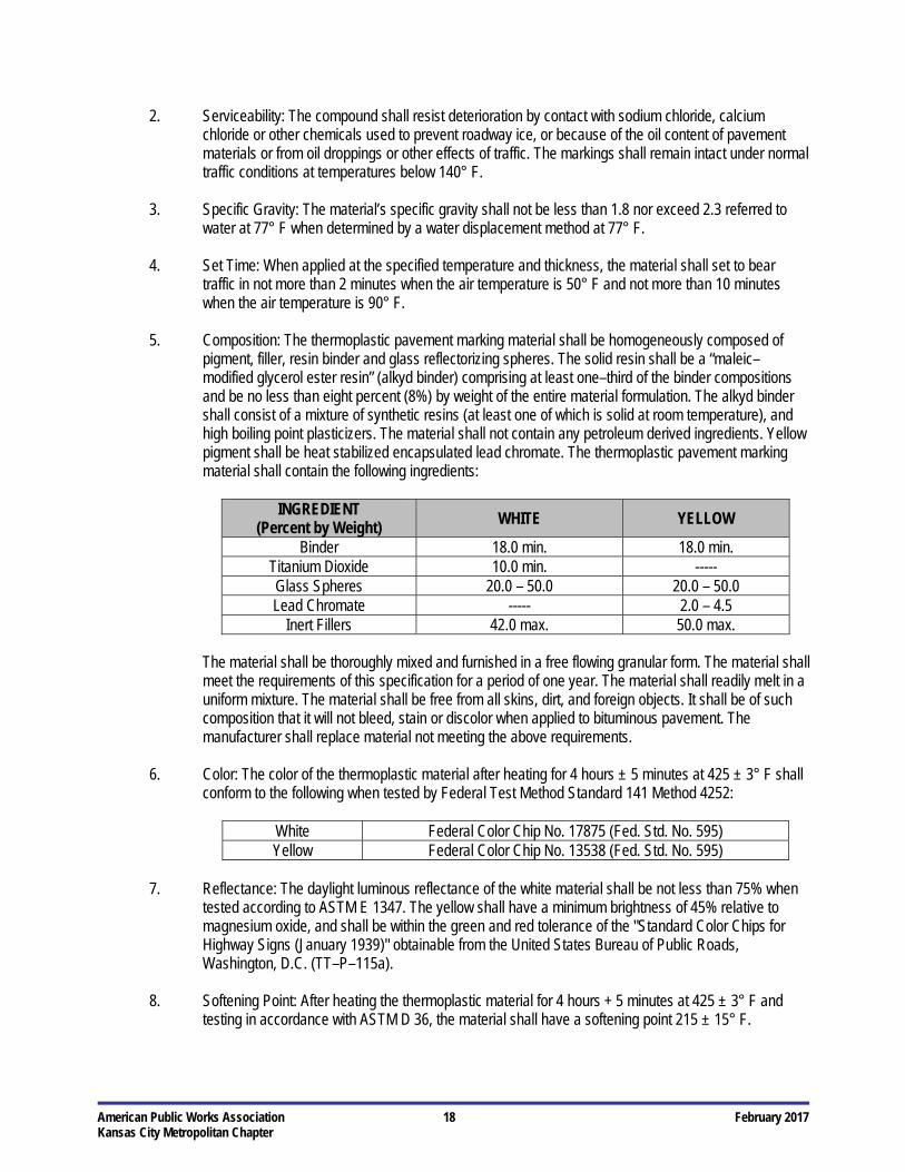
5. Composition: The thermoplastic pavement marking material shall be homogeneously composed of
pigment, filler, resin binder and glass reflectorizing spheres. The solid resin shall be a “maleic–modified glycerol ester resin” (alkyd binder) comprising at least one–third of the binder compositions and be no less than eight percent (8%) by weight of the entire material formulation. The alkyd binder shall consist of a mixture of synthetic resins (at least one of which is solid at room temperature), and high boiling point plasticizers. The material shall not contain any petroleum derived ingredients. Yellow pigment shall be heat stabilized encapsulated lead chromate. The thermoplastic pavement marking material shall contain the following ingredients:
INGREDIENT
(Percent by Weight) WHITE YELLOW
Binder 18.0 min. 18.0 min. Titanium Dioxide 10.0 min. ----- Glass Spheres 20.0 – 50.0 20.0 – 50.0 Lead Chromate ----- 2.0 – 4.5
Inert Fillers 42.0 max. 50.0 max.
The material shall be thoroughly mixed and furnished in a free flowing granular form. The material shall meet the requirements of this specification for a period of one year. The material shall readily melt in a uniform mixture. The material shall be free from all skins, dirt, and foreign objects. It shall be of such composition that it will not bleed, stain or discolor when applied to bituminous pavement. The manufacturer shall replace material not meeting the above requirements.
6. Color: The color of the thermoplastic material after heating for 4 hours ± 5 minutes at 425 ± 3° F shall
conform to the following when tested by Federal Test Method Standard 141 Method 4252:
White Federal Color Chip No. 17875 (Fed. Std. No. 595) Yellow Federal Color Chip No. 13538 (Fed. Std. No. 595)
7. Reflectance: The daylight luminous reflectance of the white material shall be not less than 75% when
tested according to ASTM E 1347. The yellow shall have a minimum brightness of 45% relative to magnesium oxide, and shall be within the green and red tolerance of the "Standard Color Chips for Highway Signs (January 1939)" obtainable from the United States Bureau of Public Roads, Washington, D.C. (TT–P–115a).
8. Softening Point: After heating the thermoplastic material for 4 hours + 5 minutes at 425 ± 3° F and
testing in accordance with ASTM D 36, the material shall have a softening point 215 ± 15° F.
American Public Works Association 19 February 2017 Kansas City Metropolitan Chapter
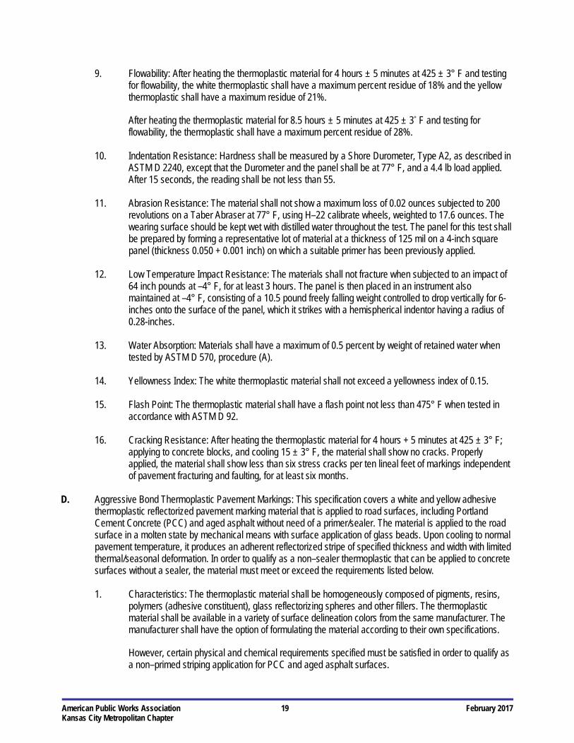
9. Flowability: After heating the thermoplastic material for 4 hours ± 5 minutes at 425 ± 3° F and testing for flowability, the white thermoplastic shall have a maximum percent residue of 18% and the yellow thermoplastic shall have a maximum residue of 21%.
After heating the thermoplastic material for 8.5 hours ± 5 minutes at 425 ± 3° F and testing for flowability, the thermoplastic shall have a maximum percent residue of 28%.
10. Indentation Resistance: Hardness shall be measured by a Shore Durometer, Type A2, as described in
ASTM D 2240, except that the Durometer and the panel shall be at 77° F, and a 4.4 lb load applied. After 15 seconds, the reading shall be not less than 55.
11. Abrasion Resistance: The material shall not show a maximum loss of 0.02 ounces subjected to 200
revolutions on a Taber Abraser at 77° F, using H–22 calibrate wheels, weighted to 17.6 ounces. The wearing surface should be kept wet with distilled water throughout the test. The panel for this test shall be prepared by forming a representative lot of material at a thickness of 125 mil on a 4-inch square panel (thickness 0.050 + 0.001 inch) on which a suitable primer has been previously applied.
12. Low Temperature Impact Resistance: The materials shall not fracture when subjected to an impact of
64 inch pounds at –4° F, for at least 3 hours. The panel is then placed in an instrument also maintained at –4° F, consisting of a 10.5 pound freely falling weight controlled to drop vertically for 6-inches onto the surface of the panel, which it strikes with a hemispherical indentor having a radius of 0.28-inches.
13. Water Absorption: Materials shall have a maximum of 0.5 percent by weight of retained water when
tested by ASTM D 570, procedure (A).
14. Yellowness Index: The white thermoplastic material shall not exceed a yellowness index of 0.15.
15. Flash Point: The thermoplastic material shall have a flash point not less than 475° F when tested in accordance with ASTM D 92.
16. Cracking Resistance: After heating the thermoplastic material for 4 hours + 5 minutes at 425 ± 3° F;
applying to concrete blocks, and cooling 15 ± 3° F, the material shall show no cracks. Properly applied, the material shall show less than six stress cracks per ten lineal feet of markings independent of pavement fracturing and faulting, for at least six months.
D. Aggressive Bond Thermoplastic Pavement Markings: This specification covers a white and yellow adhesive
thermoplastic reflectorized pavement marking material that is applied to road surfaces, including Portland Cement Concrete (PCC) and aged asphalt without need of a primer/sealer. The material is applied to the road surface in a molten state by mechanical means with surface application of glass beads. Upon cooling to normal pavement temperature, it produces an adherent reflectorized stripe of specified thickness and width with limited thermal/seasonal deformation. In order to qualify as a non–sealer thermoplastic that can be applied to concrete surfaces without a sealer, the material must meet or exceed the requirements listed below.
1. Characteristics: The thermoplastic material shall be homogeneously composed of pigments, resins,
polymers (adhesive constituent), glass reflectorizing spheres and other fillers. The thermoplastic material shall be available in a variety of surface delineation colors from the same manufacturer. The manufacturer shall have the option of formulating the material according to their own specifications.
However, certain physical and chemical requirements specified must be satisfied in order to qualify as a non–primed striping application for PCC and aged asphalt surfaces.
American Public Works Association 20 February 2017 Kansas City Metropolitan Chapter
The material shall not exude fumes which are toxic or injurious to persons or properties upon heating to application temperature.
2. Specific Gravity: The specific gravity of the white and yellow thermoplastic pavement marking material
shall not exceed 2.15.
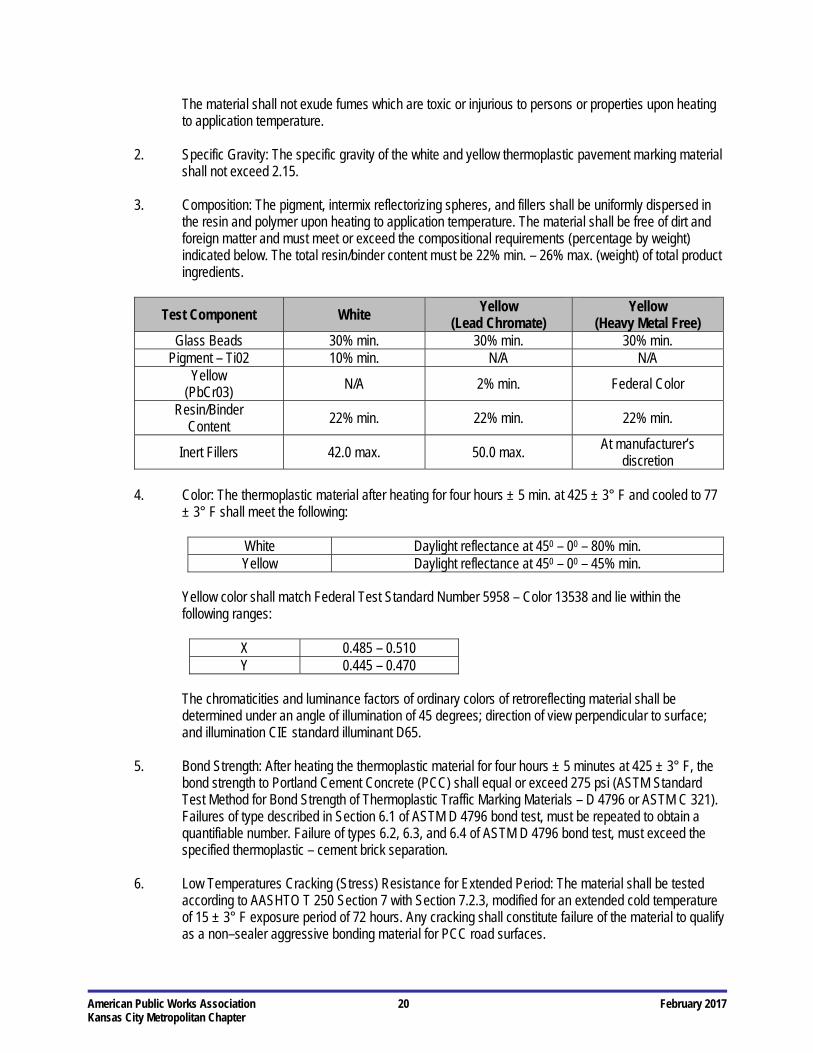
3. Composition: The pigment, intermix reflectorizing spheres, and fillers shall be uniformly dispersed in the resin and polymer upon heating to application temperature. The material shall be free of dirt and foreign matter and must meet or exceed the compositional requirements (percentage by weight) indicated below. The total resin/binder content must be 22% min. – 26% max. (weight) of total product ingredients.
Test Component White Yellow
(Lead Chromate) Yellow
(Heavy Metal Free) Glass Beads 30% min. 30% min. 30% min.
Pigment – Ti02 10% min. N/A N/A Yellow
(PbCr03) N/A 2% min. Federal Color
Resin/Binder Content
22% min. 22% min. 22% min.
Inert Fillers 42.0 max. 50.0 max. At manufacturer’s
discretion
4. Color: The thermoplastic material after heating for four hours ± 5 min. at 425 ± 3° F and cooled to 77 ± 3° F shall meet the following:
White Daylight reflectance at 450 – 00 – 80% min. Yellow Daylight reflectance at 450 – 00 – 45% min.
Yellow color shall match Federal Test Standard Number 5958 – Color 13538 and lie within the following ranges:
X 0.485 – 0.510 Y 0.445 – 0.470
The chromaticities and luminance factors of ordinary colors of retroreflecting material shall be determined under an angle of illumination of 45 degrees; direction of view perpendicular to surface; and illumination CIE standard illuminant D65.
5. Bond Strength: After heating the thermoplastic material for four hours ± 5 minutes at 425 ± 3° F, the
bond strength to Portland Cement Concrete (PCC) shall equal or exceed 275 psi (ASTM Standard Test Method for Bond Strength of Thermoplastic Traffic Marking Materials – D 4796 or ASTM C 321). Failures of type described in Section 6.1 of ASTM D 4796 bond test, must be repeated to obtain a quantifiable number. Failure of types 6.2, 6.3, and 6.4 of ASTM D 4796 bond test, must exceed the specified thermoplastic – cement brick separation.
6. Low Temperatures Cracking (Stress) Resistance for Extended Period: The material shall be tested
according to AASHTO T 250 Section 7 with Section 7.2.3, modified for an extended cold temperature of 15 ± 3° F exposure period of 72 hours. Any cracking shall constitute failure of the material to qualify as a non–sealer aggressive bonding material for PCC road surfaces.
American Public Works Association 21 February 2017 Kansas City Metropolitan Chapter
7. Impact Resistance (Gardner Falling Weight): The test specimens should be formed according to the
following procedure:
Heat approximately 14.1 ounces of material in an open pint can for 4 hours at 425 ± 3° F. Preheat specimen draw down blade, 2-inches x 4-inches with a 1/8-inch die opening for approximately one hour at 425 ± 3° F. The blade is usually placed in the oven containing the sample material during the last hour of sample heating.
After heating the sample for four hours, remove the sample and the draw down blade from the oven. Place the 125–mil blade onto a PCC block. Quickly pour the sample 425 ± 30 F into the opening of the draw down screed and draw down the sample for the entire length of the concrete block. Allow the drawn down test sample to condition in the open in the standard laboratory atmosphere, 73.4 ± 30 F and 50 ± 5% relative humidity.
Perform the testing procedure according to ASTM D 5420 Section 11. Record and report the type of failure as (a) crack or cracks on the surface, (b) cracks that penetrate the entire thickness, (c) brittle shatter (the test specimen in several pieces after impact), or (d) ductile failure (the specimen is penetrated by a blunt tear).
Both the yellow and white non–sealer materials shall have minimum impact resistance of 80 inch pounds with no visible surface cracks.
8. Impact Resistance (Notched Izod): After heating the material for four hours ± 5 minutes at 425 ± 3° F
and forming test specimens according to AASHTO T 250 Section 8, both the yellow and white samples shall be a minimum notched impact resistance of 11.0 ± 0.3 inch pounds. The specimens shall be tested both at room temperature 73.4 ± 3° F and low temperature of 15 ± 3° F in accordance with ASTM D 256 test method A.
9. Oil and Grease Resistance: The thermoplastic material shall show no signs of deterioration or solubility
after motor oil is rubbed vigorously into a sample for 2 minutes and allowed to penetrate for 5 minutes.
10. Set Time: When applied at a temperature range of 412.5 ± 12.5° F and thickness of 90 to 125 mil the material shall set to bear traffic in not more than 2-minutes when the air temperature is 50 ± 3° F and not more than ten minutes when the air temperature is 90 ± 3° F.
11. Flash Point: The thermoplastic material shall have a flash point of not less than 500° F when tested in
accordance with ASTM D 92.
12. Storage Life: The material shall maintain the requirements of this specification for a minimum period of one year. The thermoplastic material must melt uniformly with no evidence of skins or unmelted particles for this one year time period. Any material failing to do so shall be replaced by the manufacturer at their expense.
13. Packaging and Marking: The thermoplastic material shall be packaged in suitable containers to which
it will not adhere during shipment and storage. The container of thermoplastic material shall weigh approximately 50 lbs. Each container shall designate user information, manufacturer’s name and address, batch number and date of manufacture. Each batch manufactured shall have its own separate number. The label shall carry appropriate user warnings and instructions.
14. NTPEP Test Program: The material must have been applied, without surface primer, on two NTPEP

American Public Works Association 22 February 2017 Kansas City Metropolitan Chapter
Decks (PCC) and evaluated for a period of at least one year. A minimum of 90% of the original pavement striping must be intact on the PCC decks after a one–year review period. The percent retention is calculated based on the measured test area square footage (neglecting mil thickness wear down) minus the road surface areas that are exposed due to cracking and chipping away of thermoplastic from the concrete surface caused by product bond failure to the substrate.
E. Preformed Thermoplastic Pavement Markings: This specification is for the furnishing of retroreflective
preformed thermoplastic pavement marking materials that can be adhered to asphalt, concrete and Portland cement concrete pavements by means of heat fusion. The applied markings shall be very durable, oil and grease impervious and provide immediate and continuing retroreflectivity.
1. Characteristics: The preformed marking material shall consist of a resilient white and yellow polymer
thermoplastic with uniformly distributed glass beads throughout its entire cross section.
Preformed words and symbols shall conform to the applicable shapes and sizes as prescribed in the latest revision of the Manual on Uniform Traffic Control Devices (MUTCD).
The preformed markings shall be fusible to asphalt concrete and Portland cement concrete pavements by means of the normal heat of a propane type of torch. Adhesives, primers or sealers shall not be used prior to the preformed marking application on asphalt concrete and Portland cement concrete pavements.
The preformed markings shall conform to pavement contours, breaks and faults through the action of traffic at normal pavement temperatures. The markings shall have resealing characteristics and be capable of fusing to itself and previously applied worn hydrocarbon and/or alkyd thermoplastic pavement markings.
The preformed markings shall be capable of application on new, dense and open graded asphalt concrete wearing courses during the paving operation in accordance with the manufacturer’s instructions. After application, the markings shall be immediately ready for traffic. The preformed markings shall be suitable for use for one year after the date of receipt when stored in accordance with the manufacturer’s recommendations.
The preformed thermoplastic markings shall not be brittle and must be sufficiently cohesive and flexible at temperatures exceeding 50 degrees F for one person to carry without the danger of fracturing the material prior to application.
2. Composition: The retroreflective pliant polymer thermoplastic pavement markings shall consist of a
homogeneous mixture of high quality polymeric thermoplastic binders, pigments, fillers and glass beads. The thermoplastic material must conform to AASHTO designation M 249 with the exception of the relevant differences due to the material being supplied in a preformed state.
3. Glass Beads: The markings shall contain 30% glass spheres which shall conform to AASHTO M 247
Type 1, except that glass spheres shall have a minimum of 70% true spheres on each sieve and 80% true spheres overall.
The glass beads must be homogeneously blended throughout the material with a securely bonded protruding exposed layer of beads that provide immediate and continuous retroreflectivity; no additional glass beads shall be dropped on the material during application. Curved arrows must be available without protruding glass beads if reversibility is needed.

American Public Works Association 23 February 2017 Kansas City Metropolitan Chapter
4. Retroreflectivity: The preformed marking shall upon application exhibit uniform adequate nighttime retroreflectivity when tested in accordance with ASTM E 1710. At 86 degree 30 feet incidence angle and 1 degree 30-feet divergence angle, the markings shall have average minimum intensities of 350 millicandelas for white and 175 millicandelas for yellow as measured with a Mirolux or LTL-2000 retroreflectometer. Follow manufacturer’s instructions for use.
Using a Taber Abraser with an H–18 wheel and a 4.4 ounce load, the sample shall be inspected at 200 cycles, under a microscope, to observe the extent and type of bead failure. No more than 15% of the beads shall be lost due to popout and the predominant mode of failure shall be “wear down” of the beads.
5. Color Characteristics: The thermoplastic material without glass beads shall meet the following:
White Daylight reflectance at 450 / 00 of 80% min. Yellow Daylight reflectance at 450 / 00 of 45% min.
The daylight reflectance shall not change significantly when the preformed thermoplastic is properly applied to the roadway surface.
For highway use, the white markings shall contain a minimum of 8% by weight of Titanium Dioxide pigment to ensure a color similar to Federal Highway White, Color No. 17886 Standard 595. Yellow color shall reasonably match color chip Number 13538 of Federal Standard 595 and be lead free.
6. Skid Resistance: The surface of the preformed thermoplastic markings shall provide a minimum skid
resistance value of 45 BPN when tested according to ASTM E 303.
7. Thickness: The width of the supplied material shall have a minimum average thickness of 90 mils.
8. Flexibility: The preformed thermoplastic marking material shall have flexibility at 50° F such that no cracking occurs in the test sample when a 1-inch by 6-inches sample is bent through an arc of 900 at a uniform rate in 10 seconds (9 seconds per degree) over a one inch mandrel. The sample must be conditioned prior to testing at 50 ± 2° F for a minimum of four hours. At least two specimens tested must meet the flexibility requirements at 50° F for a passing result.
9. Environmental Resistance: The applied markings shall be resistant to deterioration due to exposure to
sunlight, water, oil, diesel fuels, gasoline, pavement oil content, salt, and adverse weather conditions.
10. Effective Performance Life: When properly applied, in accordance with the manufacturer’s instructions, the pavement markings shall be neat and durable. The markings shall remain retroreflective and show no fading, lifting, shrinkage, tearing, roll back or other signs of poor adhesion.
F. Cold Plastic Pavement Markings: This specification covers a white and yellow pre–formed cold plastic
reflectorized pavement marking material of a type that is applied to a road surface by an inlaid, pre–coated pressure sensitive adhesive that produces an adherent reflectorized stripe of specified thickness and width and is capable of resisting deformation.
1. Characteristics: The material shall be manufactured without the use of lead–chromate pigments or
other, similar, lead–containing chemicals.
Glass beads shall be incorporated to provide immediate and continuing retroreflection. Ceramic skid particles shall be bonded to the top layer to provide a skid–resistant surface.
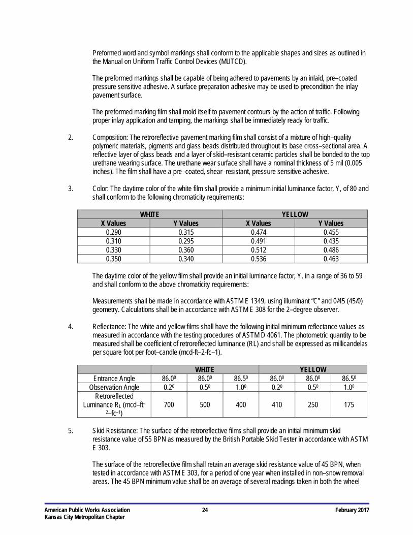
American Public Works Association 24 February 2017 Kansas City Metropolitan Chapter
Preformed word and symbol markings shall conform to the applicable shapes and sizes as outlined in the Manual on Uniform Traffic Control Devices (MUTCD).
The preformed markings shall be capable of being adhered to pavements by an inlaid, pre–coated pressure sensitive adhesive. A surface preparation adhesive may be used to precondition the inlay pavement surface.
The preformed marking film shall mold itself to pavement contours by the action of traffic. Following proper inlay application and tamping, the markings shall be immediately ready for traffic.
2. Composition: The retroreflective pavement marking film shall consist of a mixture of high–quality
polymeric materials, pigments and glass beads distributed throughout its base cross–sectional area. A reflective layer of glass beads and a layer of skid–resistant ceramic particles shall be bonded to the top urethane wearing surface. The urethane wear surface shall have a nominal thickness of 5 mil (0.005 inches). The film shall have a pre–coated, shear–resistant, pressure sensitive adhesive.
3. Color: The daytime color of the white film shall provide a minimum initial luminance factor, Y, of 80 and
shall conform to the following chromaticity requirements:
WHITE YELLOW X Values Y Values X Values Y Values
0.290 0.315 0.474 0.455 0.310 0.295 0.491 0.435 0.330 0.360 0.512 0.486 0.350 0.340 0.536 0.463
The daytime color of the yellow film shall provide an initial luminance factor, Y, in a range of 36 to 59 and shall conform to the above chromaticity requirements:
Measurements shall be made in accordance with ASTM E 1349, using illuminant “C” and 0/45 (45/0) geometry. Calculations shall be in accordance with ASTM E 308 for the 2–degree observer.
4. Reflectance: The white and yellow films shall have the following initial minimum reflectance values as
measured in accordance with the testing procedures of ASTM D 4061. The photometric quantity to be measured shall be coefficient of retroreflected luminance (RL) and shall be expressed as millicandelas per square foot per foot–candle (mcd-ft–2-fc–1).
WHITE YELLOW
Entrance Angle 86.00 86.00 86.50 86.00 86.00 86.50 Observation Angle 0.20 0.50 1.00 0.20 0.50 1.00
Retroreflected Luminance RL (mcd–ft–
2–fc–1) 700 500 400 410 250 175
5. Skid Resistance: The surface of the retroreflective films shall provide an initial minimum skid
resistance value of 55 BPN as measured by the British Portable Skid Tester in accordance with ASTM E 303.
The surface of the retroreflective film shall retain an average skid resistance value of 45 BPN, when tested in accordance with ASTM E 303, for a period of one year when installed in non–snow removal areas. The 45 BPN minimum value shall be an average of several readings taken in both the wheel
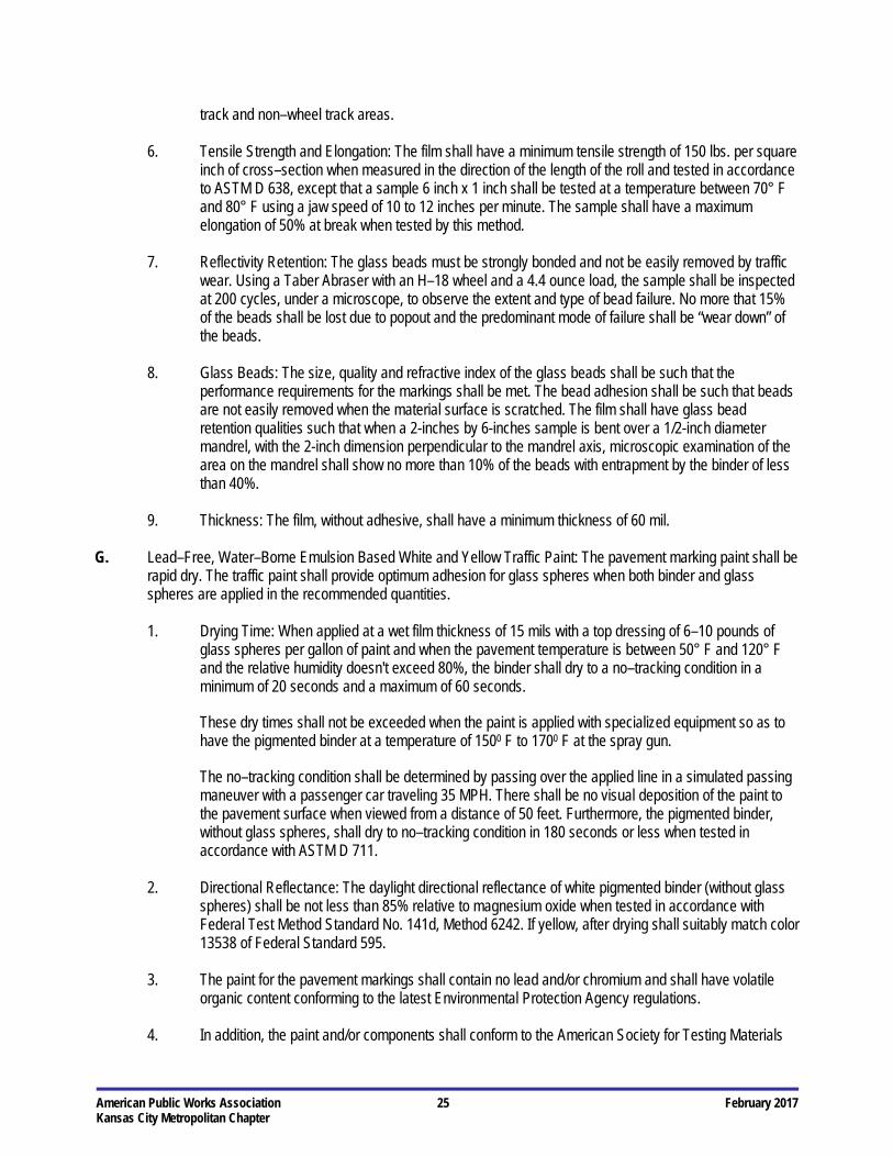
American Public Works Association 25 February 2017 Kansas City Metropolitan Chapter
track and non–wheel track areas.
6. Tensile Strength and Elongation: The film shall have a minimum tensile strength of 150 lbs. per square inch of cross–section when measured in the direction of the length of the roll and tested in accordance to ASTM D 638, except that a sample 6 inch x 1 inch shall be tested at a temperature between 70° F and 80° F using a jaw speed of 10 to 12 inches per minute. The sample shall have a maximum elongation of 50% at break when tested by this method.
7. Reflectivity Retention: The glass beads must be strongly bonded and not be easily removed by traffic
wear. Using a Taber Abraser with an H–18 wheel and a 4.4 ounce load, the sample shall be inspected at 200 cycles, under a microscope, to observe the extent and type of bead failure. No more that 15% of the beads shall be lost due to popout and the predominant mode of failure shall be “wear down” of the beads.
8. Glass Beads: The size, quality and refractive index of the glass beads shall be such that the
performance requirements for the markings shall be met. The bead adhesion shall be such that beads are not easily removed when the material surface is scratched. The film shall have glass bead retention qualities such that when a 2-inches by 6-inches sample is bent over a 1/2-inch diameter mandrel, with the 2-inch dimension perpendicular to the mandrel axis, microscopic examination of the area on the mandrel shall show no more than 10% of the beads with entrapment by the binder of less than 40%.
9. Thickness: The film, without adhesive, shall have a minimum thickness of 60 mil.
G. Lead–Free, Water–Borne Emulsion Based White and Yellow Traffic Paint: The pavement marking paint shall be
rapid dry. The traffic paint shall provide optimum adhesion for glass spheres when both binder and glass spheres are applied in the recommended quantities.
1. Drying Time: When applied at a wet film thickness of 15 mils with a top dressing of 6–10 pounds of
glass spheres per gallon of paint and when the pavement temperature is between 50° F and 120° F and the relative humidity doesn't exceed 80%, the binder shall dry to a no–tracking condition in a minimum of 20 seconds and a maximum of 60 seconds.
These dry times shall not be exceeded when the paint is applied with specialized equipment so as to have the pigmented binder at a temperature of 1500 F to 1700 F at the spray gun.
The no–tracking condition shall be determined by passing over the applied line in a simulated passing maneuver with a passenger car traveling 35 MPH. There shall be no visual deposition of the paint to the pavement surface when viewed from a distance of 50 feet. Furthermore, the pigmented binder, without glass spheres, shall dry to no–tracking condition in 180 seconds or less when tested in accordance with ASTM D 711.
2. Directional Reflectance: The daylight directional reflectance of white pigmented binder (without glass
spheres) shall be not less than 85% relative to magnesium oxide when tested in accordance with Federal Test Method Standard No. 141d, Method 6242. If yellow, after drying shall suitably match color 13538 of Federal Standard 595.
3. The paint for the pavement markings shall contain no lead and/or chromium and shall have volatile
organic content conforming to the latest Environmental Protection Agency regulations.
4. In addition, the paint and/or components shall conform to the American Society for Testing Materials
American Public Works Association 26 February 2017 Kansas City Metropolitan Chapter
(ASTM) as follows:
D 93 Standard Test Methods for Flash Point by Pensky Martens Closed Tester D 476 Standard Specification for Titanium Dioxide Pigments, Type II Rutile D 562 Standard Test Method for Consistency of Paints Using Stormer Viscosimeter D 711 Standard Test Method for No–Pick–Up Time of Traffic Paint D 768 Standard Specification for Yellow Iron Oxide D 868 Standard Test Method for Evaluating Degree of Bleeding of Traffic Paint D 1152 Standard Specification for Methanol (Methyl Alcohol) D 1199 Standard Specification for Calcium Carbonate Pigments D 1210 Standard Test Method for Fineness of Dispersion of Pigment–Vehicle Systems by
Hegman–Type Gage D 1475 Standard test Method for Density of Paint, Varnish, Lacquer, and Related Products D 2243 Standard Test Method for Freeze–Thaw Resistance of Waterborne Coatings D 2369 Standard Test Method for Volatile Content of Coatings D 2805 Standard Test Method for Hiding Power of Paints by Reflectometry D 3723 Standard Test Method for Pigment Content of Water Emulsion by Low Temperature Ashing D 3960 Standard Practice for Determining Volatile Organic Content (VOC) of Paints and Related
Coatings D 4060 Standard Test Method for Abrasion Resistance of Organic Coatings by Taber Abraser D 4366 Standard Test Methods for Hardness of Organic Coatings by Pendulum Damping Tests E 70 Standard Test Method for pH of Aqueous Solutions With the Glass Electrode E 1347 Standard Test Method for Color and Color–Difference Measurement by Tristimulus (Filter)
Colorimetry
The paint shall show no cracking, flaking, blistering, appreciable loss of adhesion, softening, coagulation, discoloration, and have a minimum bleeding ratio of 0.97 when tested in accordance with Federal Specification TT–P–1952B.
The paint shall be capable of dilution with water at all levels without curdling or precipitation such that the wet paint can be readily cleaned up with water only.
The minimum contrast ratio shall be 0.96 when drawing down with a 0.005 bird film applicator on a 2A Leneta Chart or equal and air–dried for 24 hours.
Contrast Ratio = Black/White. H. Temporary Tape: This specification covers pavement marking tape of two colors, white and yellow, and of two
types, Type I and Type II.
Type I Regular (This type is not required to be easily removable intact)
Type II Removable (This type is to be readily removable intact, either manually or with a roll–up device after having been in place through the construction season)
1. General: This material shall be a pavement striping tape designed to provide reflective delineation under both dry and moderate rainfall conditions. The tape shall consist of glass spheres tightly embedded to a binder; on a conformable backing pre-coated with a pressure sensitive adhesive. The striping material shall be thin, flexible, formable, and following application shall remain conformed to the texture of the pavement surface. The tape shall be furnished in the color and type designated on the Plans or in the Contract Documents. The markings shall be pre-coated with a pressure sensitive
American Public Works Association 27 February 2017 Kansas City Metropolitan Chapter
adhesive and shall be capable of being adhered to asphalt concrete or Portland cement concrete in accordance with manufacturer's instructions without the use of heat, solvents or other additional adhesive means, and shall be immediately ready for traffic after application. The adhesive shall not require a liner or release paper. The striping material shall have a uniform appearance, free from cracks and the edges shall be true, straight and unbroken. The material shall be weather resistant and show no appreciable fading, lifting or shrinkage when applied in accordance with the manufacturer's recommendations.
2. Color and Daylight Reflectance: The daylight reflectance (ASTM E 1347) of white shall be not less
than 70%. The color of yellow shall be within the red and green tolerance limits of the Highway Yellow Color Tolerance Chart issued by the U.S. Department of Transportation.
3. Dimensions: The width and length shall be as shown on the Plans or in the Contract Documents. The
material shall be available in rolls and there shall be no more than three splices per 50 yards of length.
4. Packaging: The material shall be packaged in accordance with accepted commercial standards and when stored under normal conditions, shall be suitable for use for a period of at least one year after purchase.
5. Adhesion: The material shall adhere to asphalt and concrete surfaces when applied according to
manufacturer's recommendations at surface temperatures above 50° F and shall be immediately ready for traffic following application.
6. Removability: Type II tape shall be removable from asphalt and Portland cement concrete intact or in
large pieces, either manually or with a roll–up device, at temperatures above 40° F without use of heat, solvents, grinding or blasting.
7. Reflection: The white and yellow material shall be retroreflective, reflecting white or yellow respectively
and shall be readily visible at night when viewed with automobile headlamps using high beams from a distance of at least 300 feet.
8. Durability: Type Il material shall maintain adhesion, show no alligatoring, show no signs of pulling
apart, and shall suffer no more than a 25% loss of beads, sand and grit when subjected to 30,000 revolutions on a small–wheel circular track as described in ASTM E 660, with the following variations or exceptions:
a. Two opposite wheels mounted with Goodyear 3.40–5 NHS Industrial Rib tires shall be used
with a total load of 51.5 pounds on each tire. Tire air pressure shall be maintained at 25 pounds. The wheels shall be mounted perpendicular to the specimens and toed out 20 to produce a slight abrading action.
b. Specimens shall be applied to 6-inch diameter dense graded bituminous concrete surface which has been compacted at 3,000 psi for two minutes. After application, the specimens shall be allowed to cure at least 16 hours before beginning the test.
I. Epoxy: This specification is for the application of epoxy resin and glass beads as reflective pavement markings
on Portland cement concrete or bituminous pavements. The epoxy resin material shall be toxic heavy metal free, two–component, 100% solids, and shall be formulated and tested to perform as a pavement marking material with glass spheres applied to the surface. The two components are an epoxy resin and an amine curing agent. The Contractor shall provide complete manufacturer’s specifications and material safety data sheets to the Engineer for all material furnished.
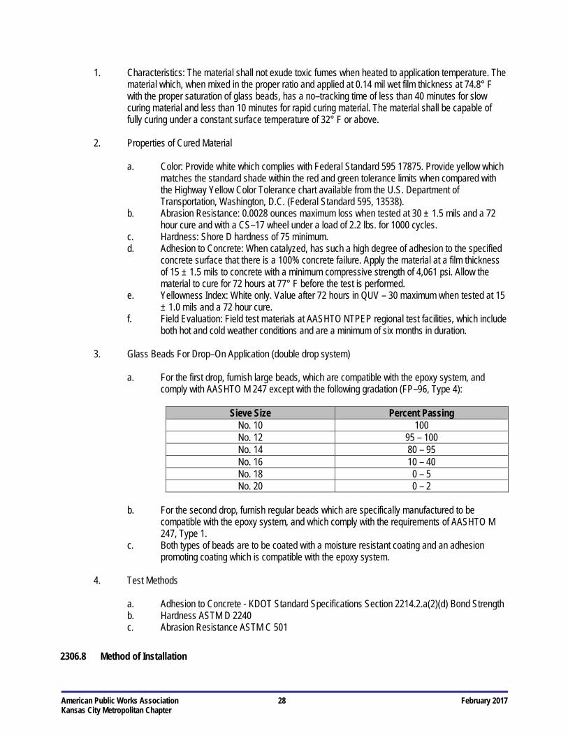
American Public Works Association 28 February 2017 Kansas City Metropolitan Chapter
1. Characteristics: The material shall not exude toxic fumes when heated to application temperature. The material which, when mixed in the proper ratio and applied at 0.14 mil wet film thickness at 74.8° F with the proper saturation of glass beads, has a no–tracking time of less than 40 minutes for slow curing material and less than 10 minutes for rapid curing material. The material shall be capable of fully curing under a constant surface temperature of 32° F or above.
2. Properties of Cured Material
a. Color: Provide white which complies with Federal Standard 595 17875. Provide yellow which
matches the standard shade within the red and green tolerance limits when compared with the Highway Yellow Color Tolerance chart available from the U.S. Department of Transportation, Washington, D.C. (Federal Standard 595, 13538).
b. Abrasion Resistance: 0.0028 ounces maximum loss when tested at 30 ± 1.5 mils and a 72 hour cure and with a CS–17 wheel under a load of 2.2 lbs. for 1000 cycles.
c. Hardness: Shore D hardness of 75 minimum. d. Adhesion to Concrete: When catalyzed, has such a high degree of adhesion to the specified
concrete surface that there is a 100% concrete failure. Apply the material at a film thickness of 15 ± 1.5 mils to concrete with a minimum compressive strength of 4,061 psi. Allow the material to cure for 72 hours at 77° F before the test is performed.
e. Yellowness Index: White only. Value after 72 hours in QUV – 30 maximum when tested at 15 ± 1.0 mils and a 72 hour cure.
f. Field Evaluation: Field test materials at AASHTO NTPEP regional test facilities, which include both hot and cold weather conditions and are a minimum of six months in duration.
3. Glass Beads For Drop–On Application (double drop system)
a. For the first drop, furnish large beads, which are compatible with the epoxy system, and
comply with AASHTO M 247 except with the following gradation (FP–96, Type 4):
Sieve Size Percent Passing No. 10 100 No. 12 95 – 100 No. 14 80 – 95 No. 16 10 – 40 No. 18 0 – 5 No. 20 0 – 2
b. For the second drop, furnish regular beads which are specifically manufactured to be
compatible with the epoxy system, and which comply with the requirements of AASHTO M 247, Type 1.
c. Both types of beads are to be coated with a moisture resistant coating and an adhesion promoting coating which is compatible with the epoxy system.
4. Test Methods
a. Adhesion to Concrete - KDOT Standard Specifications Section 2214.2.a(2)(d) Bond Strength b. Hardness ASTM D 2240 c. Abrasion Resistance ASTM C 501
2306.8 Method of Installation
American Public Works Association 29 February 2017 Kansas City Metropolitan Chapter
The proposed permanent markings shall be laid out by the Contractor as shown on the Plans in advance of the marking installation. Markings shall not be applied until the layout and conditions of the surface have been approved by the Engineer. If a paint line is used for layout purposes (in lieu of a chalk line or string line) the paint line shall not be wider than 1/2-inch in width. If wider, the paint shall be removed following the application of the final permanent marking. New markings shall match existing markings as applicable in areas abutting existing road surfaces. The surface shall be dry and all dust, debris, oil, grease, dirt, temporary markings and other foreign matter shall be removed from the road surface prior to the application of the permanent marking material.
The Contractor shall be responsible for keeping traffic off freshly applied markings until they have set sufficiently to bear traffic. Traffic control is the responsibility of the Contractor and shall conform to the MUTCD. Failure to comply with traffic control guidelines will result in the pavement marking Contractor being directed to stop operations and leave the site until proper and approved traffic control has arrived and is put in place.
Temporary pavement markings shall be installed the same day that the existing pavement markings are damaged, removed or covered up prior to lane opening.
Temporary pavement markings shall be installed using the same cycle length as the permanent markings and be at least 2-feet long. Double yellow markings shall be used for temporary centerline and single white markings shall be used for temporary lane lines on four lane roadways. Single yellow markings shall be used for temporary centerline on two lane roadways as directed by the Engineer.
Half–cycle lengths with a minimum of 2-foot stripe and 10-foot gap should be used on roadways with severe curvature. A. Glass Spheres: The drop on glass beads shall be applied at a rate of eight to ten pounds per 100 square feet. B. Thermoplastic Pavement Markings: Thermoplastic material shall readily apply to the pavement at temperatures
of 400° F to 425° F from approved equipment to produce an extruded line that shall be continuous and uniform in shape having clear and sharp dimensions. Application temperatures shall not exceed 450° F.
Thermoplastic may be used for cross walks and stop bars as specified under the conditions described herein. The thermoplastic markings shall be applied to the pavement surface in a molten state by mechanical means with surface application of glass spheres, and upon cooling to normal pavement temperature, produce an adherent retro–reflectorized stripe of specified thickness and width and capable of resisting deformation.
1. Equipment: The equipment used to install the thermoplastic shall be as follows:
a. A self–propelled machine is required in order to fulfill the timing needs of the marking
installation for longitudinal lines. b. If thermoplastic is used for transverse lines, i.e., crosswalks and stop lines, a push cart shall
be used according to the following requirements: i. Only one pass with the thermoplastic pavement marking equipment shall be allowed
in order to provide the required line width according to the Plans. ii. Multiple passes of narrower lines with overlaps to provide the required width shall
not be allowed unless otherwise approved by the Engineer after review of a test strip installation.
iii. If approved, the Contractor shall be required to heat the seam with a torch and feather the overlapped material with a putty knife. Liquid thermoplastic shall not be used for word or symbol markings.
c. Constructed to provide mixing and agitation of the materials. Conveying parts between the main material reservoir and the shaping die shall be constructed as to prevent accumulation and clogging.
American Public Works Association 30 February 2017 Kansas City Metropolitan Chapter
d. Constructed so that mixing and conveying parts up to and including the shaping die will maintain the materials at a temperature between 400° F and 450° F. To assure that the material does not fall below the minimum temperature, the shaping die shall be heated by means of a gas–fired infrared heater or a heated, oil–jacketed system.
e. Constructed as to insure continuous uniformity in the dimensions of the stripe. The applicator shall provide a means for cleanly cutting off square stripe ends and shall provide a method of applying “skip” lines. The equipment shall be constructed to be able to provide for varying die widths and to produce varying widths of traffic markings. The use of pans, aprons, or similar appliances with die overruns will not be permitted.
f. All conditions apply as stated above for material temperatures, line definition and workmanship when a hand pushcart is used for cross walks. The Engineer will verify measurement.
g. Equipment with a special kettle for melting and heating the material shall be provided. The kettle shall be equipped with a thermostat so that heating can be done by controlled heat transfer liquid rather than by direct flame so as to provide positive temperature control and prevent overheating of the material.
h. Constructed for a nominal application of 90 – 125 mil thickness. i. The heater and applicator shall be so equipped and arranged as to meet the requirements of
the National Board of Fire Underwriters of the National Fire Protection Association, of the state, and of the local authorities.
j. Equipped with an automatic glass bead dispenser attached to the striping machine in such a manner that the beads are dispensed almost instantaneously upon the installed line. The glass bead dispenser shall be equipped with an automatic cut–off control synchronized with the cut–off of the thermoplastic material.
k. The equipment shall be arranged as to permit preheating of the pavement immediately prior to application of the thermoplastic material, if preheating is recommended by the thermoplastic manufacturer.
l. The applicator shall be capable of containing a minimum of 1000 pounds of molten material (not applicable for hand–liner use).
m. The applicator shall be mobile and maneuverable to the extent that straight lines can be followed and normal curves can be made in a true arc.
n. The Contractor’s striper shall be equipped with electrical foot counters. The counters shall individually tabulate the length of line applied by each gun whether solid or dashed. The Contractor shall determine the accuracy of the foot counters and establish an adjustment factor as required to determine the pay item quantities. The foot counters shall be periodically checked to assure accurate measurements. No thermoplastic shall be applied without the accurate operation of the foot counters. The Contractor shall provide the Engineer with a certified document on these calibrations.
2. Application Over Existing Markings
a. Existing thermoplastic markings on asphalt road surfaces may be over laid with thermoplastic
material providing that the existing markings (thermoplastic) are less than 30 mils thick, and are securely bonded to the substrate. If the thermoplastic is greater than 30 mils, or not securely bonded to the substrate, then it shall be ground to 30 mils, or removed completely if not securely bonded to the road.
b. Existing solvent based paint on asphalt road surfaces may be over laid with thermoplastic provided that more than 75% of the road surface is exposed, and there is no more than a single coat of paint on the remaining unexposed area. If more than one layer of paint exists, the paint is not securely anchored to the substrate, or there is less than 75% of the road surface exposed, then the paint must be thoroughly removed.
American Public Works Association 31 February 2017 Kansas City Metropolitan Chapter
c. All existing polyester, epoxy, or other type pavement marking paints on asphalt or concrete road surfaces must be completely removed from all road surfaces prior to the installation of thermoplastic material.
3. Application Temperatures: To insure optimum adhesion, the pavement and ambient air temperature
shall be 50° F and rising. The thermoplastic material shall be applied in a melted state at a temperature of 400° F to 425° F. The temperature of the material within the shaping dies shall be maintained at the manufacturer’s recommendations for application temperatures, but in no case shall the temperature fall below 400° F or exceed 450° F.
The material shall not break down or deteriorate if held at the plastic temperature for a period of four (4) hours or by reason of three (3) reheatings to the plastic temperature (4000 F to 4250 F).
Where manufacturer’s application temperatures differ from those as specified, the manufacturer’s temperatures shall apply upon approval of the Engineer.
4. Line Quality: The finished lines shall have well defined edges and be free of waviness. Pavement
marking lines shall be straight or of uniform curvature and shall conform with the tangents, curves, and transitions as specified in the pavement marking standards and/or as directed by the Engineer.
5. Line Thickness: The minimum thickness of the lines as viewed from a lateral cross section shall be not
less than 90 mil near the edges, or less than 125 mil at the center. Drop–on glass beads shall not be included in the measurement, or if so, then appropriate allowances shall be made for the added mil thickness. A device for gauging the installed material thickness shall be furnished to the Engineer as requested for use on the project. The gauge shall be easy to read and shall readily indicate excessive variations.
6. Clean Up: The Contractor shall be responsible for removing all pavement markings material spilled
upon the roadway surface or adjoining area. The Contractor shall use methods acceptable to the Engineer for removing the spilled material.
7. Line Repair: Any pavement marking which is crossed by a vehicle and tracked shall be replaced and
any subsequent marking made by the vehicle shall be removed by methods acceptable to the Engineer at no additional cost to the Owner.
C. Preformed Thermoplastic Pavement Markings: The markings shall be applied in accordance with the
manufacturer’s recommendations on clean and dry surfaces.
1. Asphalt: The materials shall be applied using the propane torch method recommended by the manufacturer. The material must be able to be applied at ambient and road temperatures down to 32° F without any preheating of the pavement to a specific temperature. The pavement shall be clean, dry and free of debris and oil or grease residue.
a. At temperatures below 50° F, the preformed thermoplastic pavement markings shall be kept
as warm as possible to maintain flexibility. b. Remove pavement surface moisture by holding a propane torch approximately 6 inches
above the section of asphalt using a continuous circular motion. c. Heat the pavement with the torch upon placing the material to a temperature of 200° F for 90
mil, and up to 300° F for 125 mil materials. d. Immediately after the road surface has been properly preheated, position the material with
exposed bead side up and heat.
American Public Works Association 32 February 2017 Kansas City Metropolitan Chapter
e. Position the torch approximately 12-inches over the marking so the flame is extended and heat is evenly applied moving the torch in a circular motion across the marking. When the correct temperature of the marking has been reached, it will turn slightly darker or pale yellow if the material is white. Over heated or burned material shall be removed.
f. After the entire material section has been heated and bonded to the pavement, re–heat the perimeter of the marking and the road surface to bond the edges.
g. If installing reversible arrows, which do not contain a top coating of glass beads, the glass spheres shall be hand applied on the molten material.
h. Feather the leading edge of the pavement marking with a putty knife or bevel with the torch. Leading edges are any edge that would be susceptible to snow plow blades approaching from the direction of normal travel.
i. After cooling, use a putty knife to attempt to remove a portion of the material. The material shall not pry off without asphalt embedded to the underside.
2. Concrete: New concrete surfaces must be sandblasted to entirely remove curing compound. The same
application procedure shall be used as described for asphalt pavements. However, a compatible primer sealer may be applied before application to assure proper adhesion.
3. Chip Seal Surfaces: The same application procedure shall be used as described for asphalt
pavements. However, loose aggregate should be removed where the preformed thermoplastic pavement marking is to be applied.
D. Cold Plastic Pavement Markings: The Contractor shall furnish and install white and yellow permanent retro–
reflectorized cold preformed plastic pavement marking material at the location shown on the Plans, in conformance with the material specifications included herein.
The cold plastic markings shall consist of a homogeneous, extruded, prefabricated material of specified thickness and width which shall contain reflective glass spheres uniformly distributed throughout the cross–section, and shall be applied only to concrete pavement surfaces by means of an approved inlaid grinding process with pre–coated adhesive and pressure.
1. Contractor’s personnel: It is important that the Contractor’s personnel be completely knowledgeable of
all application requirements and procedures prior to product application. It is the responsibility of the Contractor to contact the supplier of the cold plastic material if questions regarding application procedures or conditions arise.
2. Procedure: This procedure explains how to apply tape to concrete surfaces only. Apply the tape
according to manufacturer’s instruction in conjunction with an approved inlaid grinding method.
3. Road conditions: It is recommended that the tape be installed as soon as practical following tape manufacturer instructions.
a. Cold plastic pavement markings shall be inlaid by an approved grooving process into
concrete pavement surfaces. Cold plastic will not be allowed on asphalt pavement surfaces whether inlaid into hot asphalt or existing asphalt surfaces. Grooving the pavement surface allows preformed pavement marking tape to better adhere by creating a fresh surface. Grooving also produces a lower profile marking by embedding the tape into the pavement surface, which helps protect the tape from snowplow damage.
b. The cutting head shall consist of diamond tipped cutting blades “gang stacked” 0.25 inches to 0.50 inches wide. The spacers between each blade must be such that there is less than a 10 mil raise in the finished groove between the blades. Water–cooling the blades may be

American Public Works Association 33 February 2017 Kansas City Metropolitan Chapter
necessary for long line grooving. c. The groove width shall be equal to the tape width plus 1 inch ± 1/8 inch. The depth of the
groove shall be 75% of the tape thickness ± 15%. For series 420, 60 mil tapes, the groove shall be 45 mils ± 10 mils or 0.05 inch ± 0.01 inch. The bottom of the groove should have a smooth, flat surface. If a coarse tooth pattern is present, increase the number of blades and decrease the thickness of the spacers between the blades on the cutting head. If water–cooling is used, flush the groove immediately after grooving to clean the surface.
d. Clean the surface of the road and the groove using a broom and/or high– pressure air blower. If either of these methods fail to clean the road surface, then high–pressure water wash shall be used. Road surface, including the surface of the groove must be dry and all dust, dirt, debris, oil, grease and foreign material removed before applying tape. If using water–cooling to groove, the groove must be completely dry prior to tape application.
4. Tape Application: If there is a crack in the pavement, or if the tape is to be applied over a bridge
expansion joint, manhole or utility box, lay the tape over the crack joint or fitting, then cut the tape 1-inch away from the crack or joint on each side. Apply the required surface preparation adhesive and allow to dry completely (5–10 minutes at 70° F, but not over 30 minutes).
5. Tamping: Tamp the tape thoroughly with a tamping cart with a minimum 200 pound load, three times
back and forth (six passes) over each part of the tape. Start in the center of the marking and work out to the edges removing any trapped air.
6. Do not twist or turn the tamper cart on the tape.
7. Make six passes (three passes back and forth) over each part of the tape (tamping is very important).
8. Make sure all edges are firmly adhered.
9. Application Conditions
a. Air temperature 60° F and rising. b. Surface temperature 70° F and rising. c. Overnight air temperature 40° F the night before tape application. d. Pavement surface must be clean and dry. No rainfall should occur within 24 hours prior to
application. e. Butt splices must be used; do not overlap tape ends. f. Traffic must be kept off of pavement surfaces coated with a surface preparation adhesive
prior to tape application (follow manufacturer’s instruction regarding the use of surface preparation adhesive).
10. Surface moisture: Cold preformed plastic tapes will not adhere if moisture is present. Therefore, road
surfaces must be dry and above the minimum required temperature for application of all tapes. If rainfall occurs within 24 hours prior to application, a surface moisture test (plastic wrap or roofing paper method as approved by the Engineer) must be performed and approval obtained from the Engineer. The groove must be visibly dry for a minimum of two hours prior to application. A moisture test shall be completed after the two–hour drying time to ensure no presence of moisture.
E. Pavement Marking Paint: The Contractor shall furnish and install white and yellow retro–reflectorized pavement
marking paint material at the location shown on the Plans, in conformance with the material specifications included herein.
American Public Works Association 34 February 2017 Kansas City Metropolitan Chapter
1. The wet thickness and dry thickness of the pavement marking paint shall not be less than 15 mils and 12 mils, respectively without glass beads.
2. Glass beads shall be applied uniformly over the entire length of line at the rate of 6 to 10 lbs. per gallon
of paint.
3. The gun tip shall be oriented perpendicular to the centerline to ensure that the beginning and ends of all lines are perpendicular to the centerline and not skewed.
4. The equipment shall be maintained such that the needle can be fully closed when shut as to ensure
square cut lines at the beginning and ends. F. Epoxy Pavement Marking: The Contractor shall furnish and install white and yellow epoxy markings at the
location shown on the Plans, in conformance with the material specifications included herein.
1. Equipment
a. Use equipment that is capable of spraying both yellow and white epoxy in the manufacturer's recommended proportions. Provide equipment that can place stripes on the left and right sides, and place two lines simultaneously with either line in a solid or intermittent pattern in yellow or white. All guns must be in full view of operators at all times. If words, symbols, crosswalks, cross–hatching and stop bars are to be of epoxy resin material, equip the truck with a hand spray wand for such application. Mount the equipment on a truck of sufficient size and stability, and with an adequate power source, to produce lines of uniform dimension and prevent application failure. Provide equipment with metering devices to register the accumulated volume dispensed for each material, each day. Additionally, provide individual pressure gauges, clearly visible to the operator, for each pump used.
b. Provide equipment with two glass bead dispensers (double drop system) that uniformly distributes the glass beads to the surface of the epoxy pavement marking at a rate of at least 25 pounds per gallon. Glass beads may be applied by a pressure gun or controlled free fall.
2. Contractor's Personnel: Assure that at least one employee on the project when pavement markings
are being applied holds an American Traffic Safety Services Association (ATSSA) pavement marking certification.
3. Surface Preparation
a. On existing pavements, remove the existing pavement markings in accordance with these
specifications. Remove the existing markings and prepare the surface according to the manufacturer's recommendations (for the type of markings being installed).
b. On new Portland cement concrete pavement (PCCP), use shot blasting to remove curing compounds and laitance from the surfaces to which the pavement marking will be applied. Prepare the surfaces of new concrete bridge decks the same as new PCCP.
c. On all pavements, thoroughly remove all dirt, grit, grease, grime, vegetable matter, residue of prior pavement marking application (including such adhesives or primers that may have been used in their application), and any other foreign matter from the roadway surface prior to the application of epoxy pavement markings.
4. Alignment: All layout required in the construction of the pavement marking is the responsibility of the
Contractor. Lay out the pavement marking as detailed on the Plans. When the Plans do not provide details, submit a layout plan (conforming to the requirements of the Manual on Uniform Traffic Control

American Public Works Association 35 February 2017 Kansas City Metropolitan Chapter
Devices (MUTCD)) for the pavement markings to the Engineer for approval. Normally locate longitudinal pavement marking stripes 2-inches from existing longitudinal joints. Provide adequate guide marks (approximately 2-inches by 6-inches at approximately 30 to 50 ft. intervals) for the application of the pavement markings.
5. Pavement Marking Application
a. When no traffic is present, and for edge lines under any condition of traffic, a slower curing
epoxy material (40 minutes) may be used. When the application is taking place under traffic, use a fast setting (10 minutes) epoxy material for center lines and skip lines.
b. Apply the epoxy material closely behind the cleaning procedure. c. Provide the Engineer with a copy of the manufacturer's application instructions. Apply the
epoxy pavement markings in accordance with the manufacturer's recommendations. In the absence of manufacturer's recommendations, apply the markings when the ambient and pavement surface temperatures are 50° F and rising. Cease pavement marking operations when the ambient or the pavement surface temperature drops to 50° F.
d. Before mixing the components of the pavement marking material, heat the individual components to the temperature ranges recommended by the manufacturer of the material. Avoid exceeding the maximum recommended temperature at any time.
e. Apply the epoxy pavement marking material at a thickness of 20 mils ± 0.2 mils on asphalt and PCCP. Immediately apply the glass beads to the epoxy pavement marking at the rate of 25 pounds per gallon of epoxy, equally divided between the large and regular bead gradations. Apply the large beads on the first drop and the regular beads on the second.
2306.9 Method of Removal
Temporary pavement markings on milled surfaces scheduled to be overlaid do not have to be removed prior to performing the overlay. Permanent pavement markings installed on new asphalt surfaces shall be removed without structurally damaging the pavement or scarring the surface. The method of pavement marking tape removal shall be by a high pressure water blast method, a low-pressure water and sand blast method, a steel shot blast method, or burning method. Grinding or black paint covering shall not be allowed on new pavement surfaces.
2306.10 Performance Measures
The Contractor shall remove and replace, at the Contractor’s expense, any finished markings that have the following deficiencies:
Drag marks, gashes, gouges, pitting, foreign covering, discoloration, or areas that have failed to solidify Improper adhesion, length, width, or thickness Glass bead inadequacy Ragged appearance with areas that do not present sharply defined edges Deviation from the specified layout by an unreasonable amount based on Engineer’s judgment
Drippings between markings shall be removed when instructed by the Engineer and shall not result in visible deterioration of the pavement.
2306.11 Method of Measurement
Pavement Markings will be measured by one of the following:

American Public Works Association 36 February 2017 Kansas City Metropolitan Chapter
A. Per linear foot of line. Skip lines are paid based upon length of marked section, 1-foot of a dual line is paid for at two unit feet bid.
B. Per each symbol.
2306.12 Basis of Payment
Pavement Markings will be paid for by one of the following: A. Contract unit bid price. B. Contract lump sum bid price.
SECTION 2307 FENCING 2307.1 Scope
This section governs the furnishing all labor, materials, and equipment for the for the installation and removal of fencing as shown on the Plans and in accordance with the Standard Drawings, the specifications and the Special Provisions.
2307.2 Referenced Standards
The following standards are referenced directly in this section. The latest version of these standards shall be used. If conflicting standards are referenced, the more stringent standard shall apply. MCIB Mid-West Concrete Industry Board Concrete Specifications - Concrete Pavement
The current editions of the "Bulletins" and Approved Sections of the "Standard Concrete Specifications" issued by the Mid-West Concrete Industry Board, Inc. (MCIB) are made a part hereof by reference. However, when the provisions of this Specification differ from the provisions of such "Bulletins" and "Sections" the provisions of this Specification shall govern.
KCMMB Kansas City Metro Materials Board Specifications Kansas Department of Transportation Standard Specifications for State Road and Bridge Construction, 2015 Edition
Section 828 – Fencing Section 1620 – Material for Fencing
Missouri Highways and Transportation Commission Missouri Standard Specifications for Highway Construction, 2011 Edition
Section 1043 Fence Materials Section 607 Chain Link Fence
2307.3 Materials A. All materials used for the installation of a permanent chain link fence shall be new material conforming to:
1. Missouri Projects: Section 1043 of the Missouri Standard Specification for highway construction except
concrete for posts shall be MCIB Mix No. A543-1-4-0.479, approved KCMMB 4K mix, or approved

American Public Works Association 37 February 2017 Kansas City Metropolitan Chapter
equal.
2. Kansas Projects: Section 1620 of the Kansas Standard Specifications for State Road and Bridge Construction except concrete for posts shall be MCIB Mix No. A543-1-4-0.479, approved KCMMB 4K mix, or approved equal.
B. All material used for the installation of permanent decorative fence shall be new material as specified or as
shown on the Plans or that match the existing fence.
2307.4 Construction A. Removal: Existing fence shall be removed as specified or as shown on the Plans or as directed by the
Engineer. Removed fencing may be used for temporary fencing only with the Engineer’s approval. Fences interfering with construction, and located within public right-of-way or as may be allowed for in permits or agreements, may be removed by the Contractor only if the opening is provided with a temporary gate that will be maintained in a closed position except to permit passage of equipment and vehicles unless otherwise specified. Fences within temporary construction easements may be removed by the Contractor provided that temporary fencing is installed in such a manner as to serve the purpose of the fencing removed. The Contractor shall locate and record all fence corners prior to removal. All fencing removed shall be restored by the Contractor to a condition equal to or better than that existing prior to construction unless otherwise specified. The Contractor is liable for loss and costs associated with stray animals caused by the removal or improper construction of temporary or permanent fencing.
B. Chain-Link Fence: Chain-Link Fence shall be installed at the locations shown on the Plans or as directed by the Engineer in accordance the applicable KDOT or MoDOT specifications for the state where the work is being performed. However, the bottom of the fabric shall be not more than 1 ½ inches above the finished ground line unless shown otherwise on the Plans. All residential fence shall have a top rail and all edges of fence fabric shall be knuckled.
C. Decorative Fence: Decorative fence shall be installed at the locations shown on the Plans or as directed by the
Engineer in accordance with the manufacturer’s instructions and recognized industry standards or as directed by the Engineer.
2307.5 Method of Measurement A. Fence shall be measured along the slope of the fence to the nearest linear foot. Vehicle gates shall not be
included in this measurement. B. Gates: Gates shall be measured per each for the size and type specified. C. Temporary Fence: Temporary fence will be measured by one of the following:
1. No measurement made.
2. Per foot measured along the slope to the nearest linear foot.
D. Fence Removal: Fence removal will be measured by one of the following:
1. No measurement made.
American Public Works Association 38 February 2017 Kansas City Metropolitan Chapter
2. Per linear foot to nearest foot.
2307.6 Basis of Payment
All items in this section will be paid for at the respective Contract unit bid price. There will be no separate payment for pedestrian gates; they are subsidiary to the fencing pay item.
SECTION 2308 STEEL BEAM GUARDRAIL 2308.1 Scope
This section governs the furnishing all labor, materials, and equipment for the for the installation of Steel Beam Guardrail as shown on the Plans and in accordance with the Standard Drawings, the specifications and the Special Provisions.
2308.2 Referenced Standards ASTM A 36 Standard Specification for Carbon Structural Steel A 123 Standard Specification for Zinc (Hot-Dip Galvanized) Coatings on Iron and Steel Products A 153 Standard Specification for Zinc Coating (Hot-Dip) on Iron and Steel Hardware AASHTO M 180 Standard Specification for Corrugated Sheet Steel Beams for Highway Guardrail
2308.3 Materials A. Steel Posts: All posts, terminal post connectors, and steel blocks for guardrail shall be formed from a structural
steel meeting the requirements of ASTM A 36, and shall be galvanized in accordance with ASTM A 123.
B. Guardrail and Hardware: All guardrail and hardware shall conform to the requirements of AASHTO M 180 Class A, Type 1. Hardware shall be galvanized in accordance with ASTM A 153. Guardrail shall be galvanized with a minimum of 1.80 ounces of Zinc per sqft. All Zinc shall be “Prime Western” grade or better.
2308.4 Construction A. Setting Posts: Posts shall be set to the depth and spaced at the intervals shown on the Plans or Standard
Drawings. They shall be set vertical and true to line and grade. Steel posts may be driven by a power hammer or may be set in dug or bored holes of a size sufficient to permit thorough compacting of the backfill around the post. The backfill material shall be dry sand, placed in layers not exceeding 12 inches in thickness to a depth of 12 inches below the finished grade. After erecting and adjusting the rail to true line and grade, the sand backfill shall be compacted by flooding. The final 12 inches of backfill consisting of suitable earth material shall then be compacted in six inch lifts. Any "mushrooming" of the top of a post shall be removed and damaged spelter coating on posts shall be repaired by the zinc alloy stick method while the surface is heated to approximately 600° F. Other methods of repairing the spelter coating shall receive prior approval of the Engineer.
B. Erecting Guardrail: Bolt holes shall be shop punched. Field punching, reaming and drilling will not be permitted. Guardrail beams shall be spliced, only at posts by lapping in the direction of traffic, using the required number of splice bolts. Beams for twisted turned down terminal sections may be either field or shop twisted. Sufficient twist shall be introduced such that the beam shall retain the required shape in a relaxed condition. Beams to be
American Public Works Association 39 February 2017 Kansas City Metropolitan Chapter
erected on a radius of 150 feet or less shall be shop-curved as shown on the Plans. Each end of every installation of guardrail shall have an end, bridge anchor, or terminal section of the design and type shown on the Plans or Standard Drawings. They shall be of the same material and shall be galvanized in accordance with the requirements for the guardrail beam. Galvanized rail shall be handled in a manner to avoid damage to the galvanized coating. Any sections of rail, end sections or terminal sections on which the spelter coating has been bruised or broken shall be rejected, or may with the prior approval of the Engineer, be repaired by the method prescribed for repairing damaged spelter coating of steel posts.
2308.5 Method of Measurement
Steel beam guardrail will be measured from center of terminal post to center of terminal post per linear foot and quarter part thereof.
2308.6 Basis of Payment
Payment will be made at the Contract unit or lump sum bid price. There will be no separate payment for terminal end sections except when specified in the Contract Documents.
END OF SECTION
![[XLS] - Mar15/District Reasi new proforma... · Web view2035 2300 2036 2300 2037 2300 2038 2300 2039 2300 2040 2300 2041 2300 2042 2300 2043 2300 2044 2300 2045 2300 2046 2300 2047](https://img.pdfslide.us/doc/110x75/5aa68dbc7f8b9a517d8ea409/xls-mar15district-reasi-new-proformaweb-view2035-2300-2036-2300-2037-2300.jpg)