Embed Size (px)
Citation preview
659-330
SECTION 23 07 11 HVAC, PLUMBING AND BOILER PLANT INSULATION
PART 1 – GENERAL
1.1 DESCRIPTION
A. Field applied insulation for thermal efficiency and condensation control for:
1. HVAC piping, ductwork and equipment.
2. Plumbing piping and equipment.
3. Re-insulation of HVAC piping, ductwork and equipment, plumbing piping and
equipment.
B. Definitions
1. ASJ: All service jacket, white finish facing or jacket.
2. Air conditioned space: Space having air temperature and/or humidity
controlled by mechanical equipment.
3. Cold: Equipment, ductwork or piping handling media at design temperature of
16 degrees C (60 degrees F) or below.
4. Concealed: Ductwork and piping above ceilings and in chases, and pipe
spaces.
5. Exposed: Piping, ductwork and equipment exposed to view in finished areas
including mechanical, Boiler Plant and electrical equipment rooms or exposed
to outdoor weather. Attics and crawl spaces where air handling units are
located are considered to be mechanical rooms. Shafts, chases, unfinished
attics, crawl spaces and pipe basements are not considered finished areas.
6. FSK: Foil-scrim-kraft facing.
7. Hot: HVAC Ductwork handling air at design temperature above 16 degrees C
(60 degrees F); HVAC and plumbing equipment or piping handling media
above 41 degrees C (105 degrees F).
8. Density: kg/m3 – kilograms per cubic meter (Pcf – pounds per cubic foot).
9. Runouts: Branch pipe connections up to 25-mm (one-inch) nominal size to fan
coil units or reheat coils for terminal units.
10. Thermal conductance: Heat flow rate through materials.
a. Flat surface: Watt per square meter (BTU per hour per square foot).
b. Pipe or Cylinder: Watt per square meter (BTU per hour per linear foot).
11. Thermal Conductivity (k): Watt per meter, per degree C (BTU per inch
thickness, per hour, per square foot, per degree F temperature difference).
12. HPS: High pressure steam (415 kPa [60 psig] and above).
13. HPR: High pressure steam condensate return.
14. MPS: Medium pressure steam (110 kPa [16 psig] thru 414 kPa [59 psig]. 2867 William G. “Bill” Hefner VAMC June 14, 2010
Mental Health Phase I Inpatient Facility HVAC, PLUMBING AND BOILER PLANT INSULATION
23 07 11-1
659-330
15. MPR: Medium pressure steam condensate return.
16. LPS: Low pressure steam (103 kPa [5 psig] and below).
17. LPR: Low pressure steam condensate gravity return.
18. PC: Pumped condensate.
19. HWH: Hot water heating supply.
20. HWHR: Hot water heating return.
21. CPD: Condensate pump discharge.
22. R: Pump recirculation.
23. CW: Cold water.
24. SW: Soft water.
25. HW: Hot water.
26. CH: Chilled water supply.
27. CHR: Chilled water return.
28. PVDC: polyvinylidene chloride vapor retarder jacketing, white.
1.2 RELATED WORK
A. Section 07 84 00, FIRESTOPPING: Mineral fiber and bond breaker behind sealant.
B. Section 23 05 11, COMMON WORK RESULTS FOR HVAC AND STEAM
GENERATION: General mechanical requirements and items, which are common to
more than one section of Division 23.
C. Section 22 05 19, METERS AND GAGES FOR PLUMBING PIPING and Section 22
05 23, GENERAL-DUTY VALVES FOR PLUMBING PIPING: Hot and cold water
piping.
D. Section 23 21 13, HYDRONIC PIPING and Section 23 22 13, STEAM AND
CONDENSATE HEATING PIPING: Piping and equipment.
E. Section 23 21 13, HYDRONIC PIPING: Chilled water piping.
F. Section 23 31 00, HVAC DUCTS AND CASINGS: Ductwork, plenum and fittings.
1.3 QUALITY ASSURANCE
A. Refer to article QUALITY ASSURANCE, in Section 23 05 11, COMMON WORK
RESULTS FOR HVAC AND STEAM GENERATION.
B. Criteria:
1. Comply with NFPA 90A, particularly paragraphs 4.3.3.1 through 4.3.3.6,
4.3.10.2.6, and 5.4.6.4, parts of which are quoted as follows:
4.3.3.1 Pipe insulation and coverings, duct coverings, duct linings, vapor retarder facings, adhesives, fasteners, tapes, and supplementary materials added to air ducts, plenums, panels and duct silencers used in duct systems, unless otherwise provided for in 4.3.3.1.2 or 4.3.3.1.3, shall have, in the form in which they are used, a maximum flame spread index of 265 without evidence of continued progressive combustion and a maximum smoke developed index of
2867 William G. “Bill” Hefner VAMC June 14, 2010 Mental Health Phase I Inpatient Facility
HVAC, PLUMBING AND BOILER PLANT INSULATION 23 07 11-2
659-330
50 when tested in accordance with NFPA 55, Standard Method of Test of Surface Burning Characteristics of Building Materials. 4.3.3.1.1 Where these products are to be applied with adhesives, they shall be tested with such adhesives applied, or the adhesives used shall have a maximum flame spread index of 25 and a maximum smoke developed index of 50 when in the final dry state (See 4.2.4.2) 4.3.3.1.2 The flame spread and smoke developed index requirements of 4.3.3.1.1 shall not apply to air duct weatherproof coverings where they are located entirely outside of a building, do not penetrate a wall or roof, and do not create an exposure hazard. 4.3.3.1.3 Smoke detectors required by 6.4.4 shall not be required to meet flame spread index or smoke developed index requirements.
4.3.3.2 Closure systems for use with rigid and flexible air ducts tested in
accordance with UL 181, Standard for Safety Factory-Made Air Ducts and Air Connectors, shall have been tested, listed, and used in accordance with the conditions of their listings, in accordance with one of the following:
(1) UL 181A, Standard for Safety Closure Systems for Use with Rigid Air Ducts and Air Connectors
(2) UL 181B, Standard for Safety Closure Systems for Use with Flexible Air Ducts and Air Connectors
4.3.3.3 Air duct, panel, and plenum coverings and linings, and pipe insulation and coverings shall not flame, glow, smolder, or smoke when tested in accordance with a similar test for pipe covering, ASTM C 411, Standard Test Method for Hot-Surface Performance of High-Temperature Thermal Insulation, at the temperature to which they are exposed in service. 4.3.3.3.1 In no case shall the test temperature be below 121°C (250°F). 4.3.3.4 Air duct coverings shall not extend through walls or floors that are required to be fire stopped or required to have a fire resistance rating, unless such coverings meet the requirements of 5.4.6.4. 4.3.3.5* Air duct linings shall be interrupted at fire dampers to prevent interference with the operation of devices. 4.3.3.6 Air duct coverings shall not be installed so as to conceal or prevent the use of any service opening. 4.3.10.2.6. Materials exposed to the airflow shall be noncombustible or limited combustible and have a maximum smoke developed index of 50 or comply with the following.
2867 William G. “Bill” Hefner VAMC June 14, 2010 Mental Health Phase I Inpatient Facility
4.3.10.2.6.1 Electrical wires and cables and optical fiber cables shall be listed as noncombustible or limited combustible and have a maximum smoke developed index of 50 or shall be listed as having a maximum peak optical density of 0.5 or less, an average optical density of 0.15 or less, and a maximum flame spread distance of 1.5 m (5 ft.) or less when tested in accordance with NFPA 262, Standard Method of Test for Flame Travel and Smoke of Wires and Cables for Use in Air-Handling Spaces.
HVAC, PLUMBING AND BOILER PLANT INSULATION 23 07 11-3
659-330
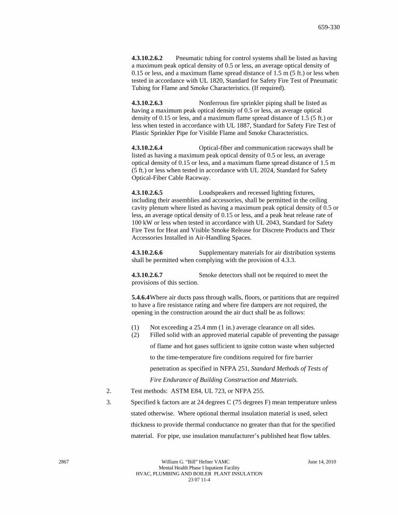
4.3.10.2.6.2 Pneumatic tubing for control systems shall be listed as having a maximum peak optical density of 0.5 or less, an average optical density of 0.15 or less, and a maximum flame spread distance of 1.5 m (5 ft.) or less when tested in accordance with UL 1820, Standard for Safety Fire Test of Pneumatic Tubing for Flame and Smoke Characteristics. (If required). 4.3.10.2.6.3 Nonferrous fire sprinkler piping shall be listed as having a maximum peak optical density of 0.5 or less, an average optical density of 0.15 or less, and a maximum flame spread distance of 1.5 (5 ft.) or less when tested in accordance with UL 1887, Standard for Safety Fire Test of Plastic Sprinkler Pipe for Visible Flame and Smoke Characteristics. 4.3.10.2.6.4 Optical-fiber and communication raceways shall be listed as having a maximum peak optical density of 0.5 or less, an average optical density of 0.15 or less, and a maximum flame spread distance of 1.5 m (5 ft.) or less when tested in accordance with UL 2024, Standard for Safety Optical-Fiber Cable Raceway. 4.3.10.2.6.5 Loudspeakers and recessed lighting fixtures, including their assemblies and accessories, shall be permitted in the ceiling cavity plenum where listed as having a maximum peak optical density of 0.5 or less, an average optical density of 0.15 or less, and a peak heat release rate of 100 kW or less when tested in accordance with UL 2043, Standard for Safety Fire Test for Heat and Visible Smoke Release for Discrete Products and Their Accessories Installed in Air-Handling Spaces. 4.3.10.2.6.6 Supplementary materials for air distribution systems shall be permitted when complying with the provision of 4.3.3. 4.3.10.2.6.7 Smoke detectors shall not be required to meet the provisions of this section.
5.4.6.4 Where air ducts pass through walls, floors, or partitions that are required to have a fire resistance rating and where fire dampers are not required, the opening in the construction around the air duct shall be as follows: (1) Not exceeding a 25.4 mm (1 in.) average clearance on all sides. (2) Filled solid with an approved material capable of preventing the passage
of flame and hot gases sufficient to ignite cotton waste when subjected
to the time-temperature fire conditions required for fire barrier
penetration as specified in NFPA 251, Standard Methods of Tests of
Fire Endurance of Building Construction and Materials.
2. Test methods: ASTM E84, UL 723, or NFPA 255.
3. Specified k factors are at 24 degrees C (75 degrees F) mean temperature unless
stated otherwise. Where optional thermal insulation material is used, select
thickness to provide thermal conductance no greater than that for the specified
material. For pipe, use insulation manufacturer’s published heat flow tables.
2867 William G. “Bill” Hefner VAMC June 14, 2010 Mental Health Phase I Inpatient Facility
HVAC, PLUMBING AND BOILER PLANT INSULATION 23 07 11-4
659-330
For domestic hot water supply and return, run out insulation and condensation
control insulation, no thickness adjustment need be made.
4. All materials shall be compatible and suitable for service temperature, and shall
not contribute to corrosion or otherwise attack surface to which applied in
either the wet or dry state.
C. Every package or standard container of insulation or accessories delivered to the job site
for use must have a manufacturer’s stamp or label giving the name of the manufacturer
and description of the material.
1.4 SUBMITTALS
A. Submit in accordance with Section 01 33 23, SHOP DRAWWINGS, PRODUCT
DATA, AND SAMPLES.
B. Shop Drawings:
1. All information, clearly presented, shall be included to determine compliance
with drawings and specifications and ASTM, federal and military
specifications.
a. Insulation materials: Specify each type used and state surface burning
characteristics.
b. Insulation facings and jackets: Each type used. Make it clear that white
finish will be furnished for exposed ductwork, casings and equipment.
c. Insulation accessory materials: Each type used.
d. Manufacturer’s installation and fitting fabrication instructions for
flexible unicellular insulation.
e. Make reference to applicable specification paragraph numbers for
coordination.
C. Samples:
1. Each type of insulation: Minimum size 100 mm (4 inches) square for
board/block/blanket; 150 mm (6 inches) long, full diameter for round types.
2. Each type of facing and jacket: Minimum size 100 mm (4 inches square).
3. Each accessory material: Minimum 120 ML (4 ounce) liquid container or 120
gram (4 ounce) dry weight for adhesives, cement, and mastic.
1.5 STORAGE AND HANDLING OF MATERIAL
Store materials in clean and dry environment, pipe covering jackets shall be clean and unmarred.
Place adhesives in original containers. Maintain ambient temperatures and conditions as required
by printed instructions of manufacturers of adhesives, mastics and finishing cements.
1.6 APPLICABLE PUBLICATIONS
2867 William G. “Bill” Hefner VAMC June 14, 2010 Mental Health Phase I Inpatient Facility
A. The publications listed below form a part of this specification to the extent referenced.
The publications are referenced in the text by basic designation only.
HVAC, PLUMBING AND BOILER PLANT INSULATION 23 07 11-5
659-330
B. Federal Specifications (Fed. Spec.):
L-P-535E (2) -91. . . . . . . . .Plastic Sheet (sheeting): Plastic Strip; Poly (Vinyl Chloride)
and Poly (Vinyl Chloride – Vinyl
Acetate), Rigid.
C. Military Specifications (Mil. Spec.):
MIL-A-3316C (2)-90. . . . . . . .Adhesives, Fire-Resistant,
Thermal Insulation.
MIL-A-24179A (1) – 87 . . . . . .Adhesive, Flexible
Unicellular-Plastic
Thermal Insulation.
MIL-C-19454C (1) – 88 . . . . . .Coating Compounds, Thermal
Insulation, Fire-and
Water-Resistant, Vapor-
Barrier
MIL-C-20079H-87. . . . . . . Cloth, Glass; Tape,
Textile Glass; and Thread,
Glass and Wire-Reinforced
Glass.
D. American Society for Testing and Materials (ASTM):
A167-99. . . . . . . . . Standard Specification for
Stainless and Heat-
Resisting Chromium-Nickel
Steel Plate, Sheet, and
Strip.
B209-04. . . . . . . . .Standard Specification for
Aluminum and Aluminum-
Alloy Sheet and Plate
C411-97. . . . . . . . .Standard test method for
Hot Surface Performance of
High-Temperature Thermal
Insulation
C449-00. . . . . . . . .Standard Specification for
Mineral Fiber Hydraulic-
Setting Thermal Insulating
and Finishing Cement
C533-04. . . . . . . . . Standard Specification for
2867 William G. “Bill” Hefner VAMC June 14, 2010 Mental Health Phase I Inpatient Facility
Calcium Silicate Block and
HVAC, PLUMBING AND BOILER PLANT INSULATION 23 07 11-6
659-330
Pipe Thermal Insulation
C534-05. . . . . . . . . Standard Specification for
Preformed Flexible
Elastomeric Cellular
Thermal Insulation in
Sheet and Tubular Form
C547-06. . . . . . . . . Standard Specification for
Mineral Fiber pipe
Insulation
C552-03. . . . . . . . . Standard Specification for
Cellular Glass Thermal
Insulation
C553-02. . . . . . . . . Standard Specification for
Mineral Fiber Blanket
Thermal Insulation for
Commercial and Industrial
Applications.
C585-90. . . . . . . . . Standard Practice for
Inner and Outer Diameters
of Rigid Thermal
Insulation for Nominal
Sizes of Pipe and Tubing
(NPS System R (1998)
C612-04. . . . . . . . . Standard Specification for
Mineral Fiber Block and
Board Thermal Insulation
C1126-04. . . . . . . . .Standard Specification for
Faced or Unfaced Rigid
Cellular Phenolic Thermal
Insulation
C1136-06. . . . . . . . . Standard Specification for
Flexible, Low Permeance
Vapor Retarders for
Thermal Insulation
E84-06. . . . . . . . . Standard Test Method for
Surface Burning Charac-
2867 William G. “Bill” Hefner VAMC June 14, 2010 Mental Health Phase I Inpatient Facility
teristics of Building
HVAC, PLUMBING AND BOILER PLANT INSULATION 23 07 11-7
659-330
Materials.
E119-05a. . . . . . . . .Standard Test Method for
Fire Tests of Building
Construction and Materials
E136-04. . . . . . . . . Standard Test Methods for
Behavior of Materials in a
Vertical Tube Furnace at
750 degrees C (1380 F)
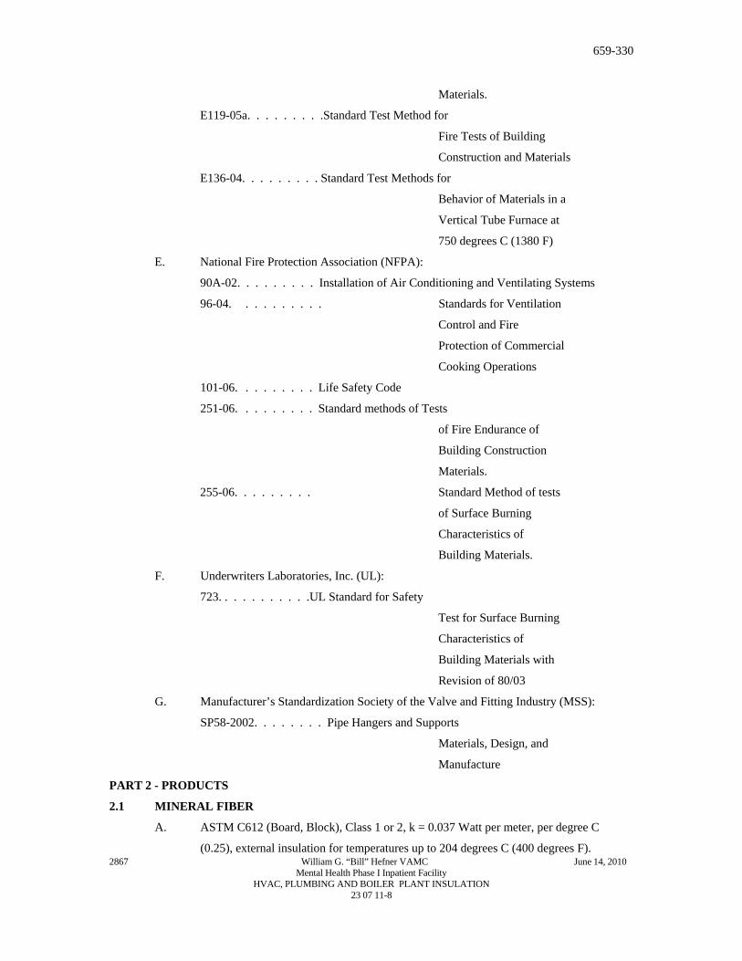
E. National Fire Protection Association (NFPA):
90A-02. . . . . . . . . Installation of Air Conditioning and Ventilating Systems
96-04. . . . . . . . . . Standards for Ventilation
Control and Fire
Protection of Commercial
Cooking Operations
101-06. . . . . . . . . Life Safety Code
251-06. . . . . . . . . Standard methods of Tests
of Fire Endurance of
Building Construction
Materials.
255-06. . . . . . . . . Standard Method of tests
of Surface Burning
Characteristics of
Building Materials.
F. Underwriters Laboratories, Inc. (UL):
723. . . . . . . . . . .UL Standard for Safety
Test for Surface Burning
Characteristics of
Building Materials with
Revision of 80/03
G. Manufacturer’s Standardization Society of the Valve and Fitting Industry (MSS):
SP58-2002. . . . . . . . Pipe Hangers and Supports
Materials, Design, and
Manufacture
PART 2 - PRODUCTS
2.1 MINERAL FIBER
2867 William G. “Bill” Hefner VAMC June 14, 2010 Mental Health Phase I Inpatient Facility
A. ASTM C612 (Board, Block), Class 1 or 2, k = 0.037 Watt per meter, per degree C
(0.25), external insulation for temperatures up to 204 degrees C (400 degrees F).
HVAC, PLUMBING AND BOILER PLANT INSULATION 23 07 11-8
659-330
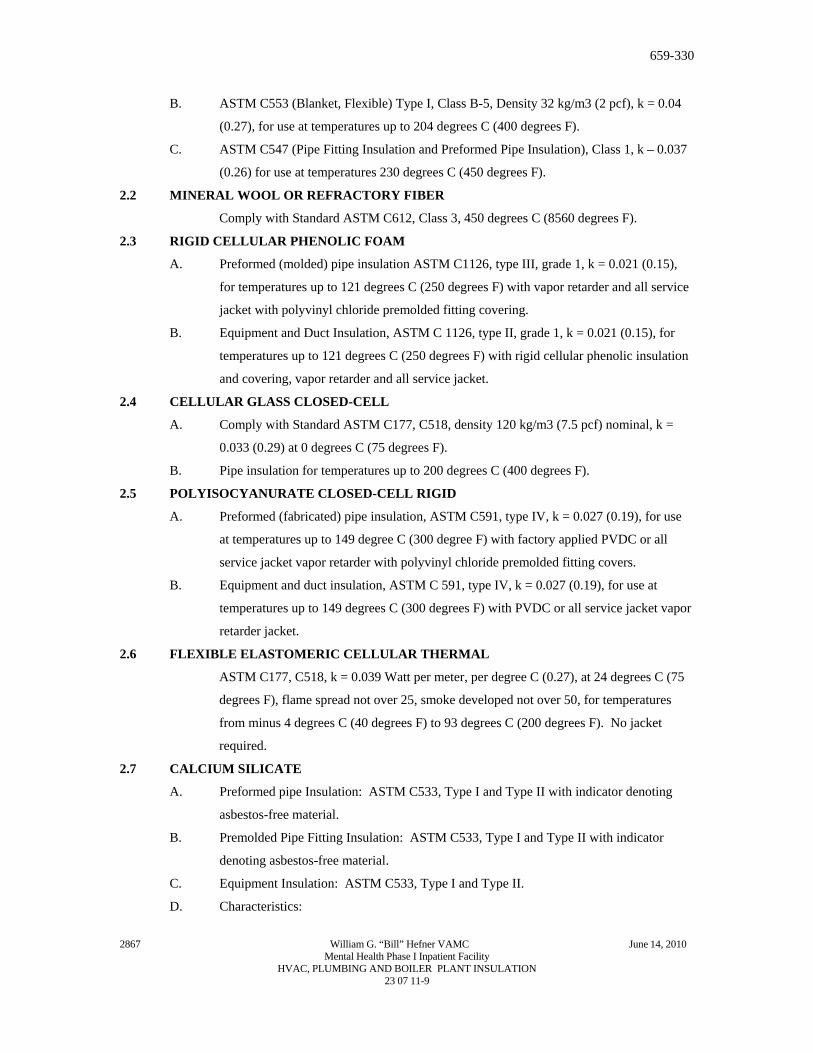
B. ASTM C553 (Blanket, Flexible) Type I, Class B-5, Density 32 kg/m3 (2 pcf), k = 0.04
(0.27), for use at temperatures up to 204 degrees C (400 degrees F).
C. ASTM C547 (Pipe Fitting Insulation and Preformed Pipe Insulation), Class 1, k – 0.037
(0.26) for use at temperatures 230 degrees C (450 degrees F).
2.2 MINERAL WOOL OR REFRACTORY FIBER
Comply with Standard ASTM C612, Class 3, 450 degrees C (8560 degrees F).
2.3 RIGID CELLULAR PHENOLIC FOAM
A. Preformed (molded) pipe insulation ASTM C1126, type III, grade 1, k = 0.021 (0.15),
for temperatures up to 121 degrees C (250 degrees F) with vapor retarder and all service
jacket with polyvinyl chloride premolded fitting covering.
B. Equipment and Duct Insulation, ASTM C 1126, type II, grade 1, k = 0.021 (0.15), for
temperatures up to 121 degrees C (250 degrees F) with rigid cellular phenolic insulation
and covering, vapor retarder and all service jacket.
2.4 CELLULAR GLASS CLOSED-CELL
A. Comply with Standard ASTM C177, C518, density 120 kg/m3 (7.5 pcf) nominal, k =
0.033 (0.29) at 0 degrees C (75 degrees F).
B. Pipe insulation for temperatures up to 200 degrees C (400 degrees F).
2.5 POLYISOCYANURATE CLOSED-CELL RIGID
A. Preformed (fabricated) pipe insulation, ASTM C591, type IV, k = 0.027 (0.19), for use
at temperatures up to 149 degree C (300 degree F) with factory applied PVDC or all
service jacket vapor retarder with polyvinyl chloride premolded fitting covers.
B. Equipment and duct insulation, ASTM C 591, type IV, k = 0.027 (0.19), for use at
temperatures up to 149 degrees C (300 degrees F) with PVDC or all service jacket vapor
retarder jacket.
2.6 FLEXIBLE ELASTOMERIC CELLULAR THERMAL
ASTM C177, C518, k = 0.039 Watt per meter, per degree C (0.27), at 24 degrees C (75
degrees F), flame spread not over 25, smoke developed not over 50, for temperatures
from minus 4 degrees C (40 degrees F) to 93 degrees C (200 degrees F). No jacket
required.
2.7 CALCIUM SILICATE
A. Preformed pipe Insulation: ASTM C533, Type I and Type II with indicator denoting
asbestos-free material.
B. Premolded Pipe Fitting Insulation: ASTM C533, Type I and Type II with indicator
denoting asbestos-free material.
C. Equipment Insulation: ASTM C533, Type I and Type II.
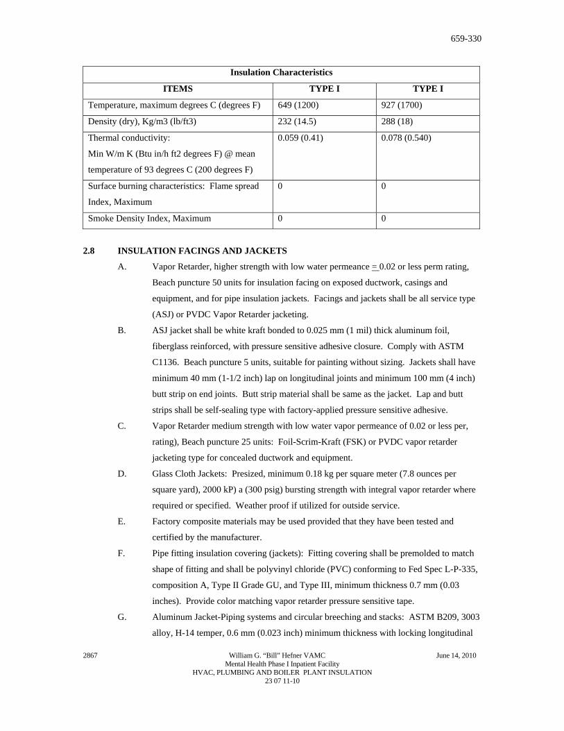
D. Characteristics:
2867 William G. “Bill” Hefner VAMC June 14, 2010 Mental Health Phase I Inpatient Facility
HVAC, PLUMBING AND BOILER PLANT INSULATION 23 07 11-9
659-330
Insulation Characteristics
ITEMS TYPE I TYPE I
Temperature, maximum degrees C (degrees F) 649 (1200) 927 (1700)
Density (dry), Kg/m3 (lb/ft3) 232 (14.5) 288 (18)
Thermal conductivity:
Min W/m K (Btu in/h ft2 degrees F) @ mean
temperature of 93 degrees C (200 degrees F)
0.059 (0.41) 0.078 (0.540)
Surface burning characteristics: Flame spread
Index, Maximum
0 0
Smoke Density Index, Maximum 0 0
2.8 INSULATION FACINGS AND JACKETS
A. Vapor Retarder, higher strength with low water permeance = 0.02 or less perm rating,
Beach puncture 50 units for insulation facing on exposed ductwork, casings and
equipment, and for pipe insulation jackets. Facings and jackets shall be all service type
(ASJ) or PVDC Vapor Retarder jacketing.
B. ASJ jacket shall be white kraft bonded to 0.025 mm (1 mil) thick aluminum foil,
fiberglass reinforced, with pressure sensitive adhesive closure. Comply with ASTM
C1136. Beach puncture 5 units, suitable for painting without sizing. Jackets shall have
minimum 40 mm (1-1/2 inch) lap on longitudinal joints and minimum 100 mm (4 inch)
butt strip on end joints. Butt strip material shall be same as the jacket. Lap and butt
strips shall be self-sealing type with factory-applied pressure sensitive adhesive.
C. Vapor Retarder medium strength with low water vapor permeance of 0.02 or less per,
rating), Beach puncture 25 units: Foil-Scrim-Kraft (FSK) or PVDC vapor retarder
jacketing type for concealed ductwork and equipment.
D. Glass Cloth Jackets: Presized, minimum 0.18 kg per square meter (7.8 ounces per
square yard), 2000 kP) a (300 psig) bursting strength with integral vapor retarder where
required or specified. Weather proof if utilized for outside service.
E. Factory composite materials may be used provided that they have been tested and
certified by the manufacturer.
F. Pipe fitting insulation covering (jackets): Fitting covering shall be premolded to match
shape of fitting and shall be polyvinyl chloride (PVC) conforming to Fed Spec L-P-335,
composition A, Type II Grade GU, and Type III, minimum thickness 0.7 mm (0.03
inches). Provide color matching vapor retarder pressure sensitive tape.
G. Aluminum Jacket-Piping systems and circular breeching and stacks: ASTM B209, 3003
alloy, H-14 temper, 0.6 mm (0.023 inch) minimum thickness with locking longitudinal
2867 William G. “Bill” Hefner VAMC June 14, 2010 Mental Health Phase I Inpatient Facility
HVAC, PLUMBING AND BOILER PLANT INSULATION 23 07 11-10
659-330
joints. Jackets for elbows, tees and other fittings shall be factory-fabricated to match
shape of fitting and of 0.6 mm (0.024) inch minimum thickness aluminum. Fittings shall
be of same construction as straight run jackets but need not be of the same alloy.
Factory-fabricated stainless steel bands shall be installed on all circumferential joints.
Bands shall be 20 mm (0.75 inch) wide on 450 mm (18 inch) centers. System shall be
weatherproof if utilized for outside service.
H. Aluminum jacket-Rectangular breeching: ASTM B209, 3003 alloy, H-14 temper, 0.5
mm (0.020 inches) thick with no corrugations. System shall be weatherproof if used for
outside service.
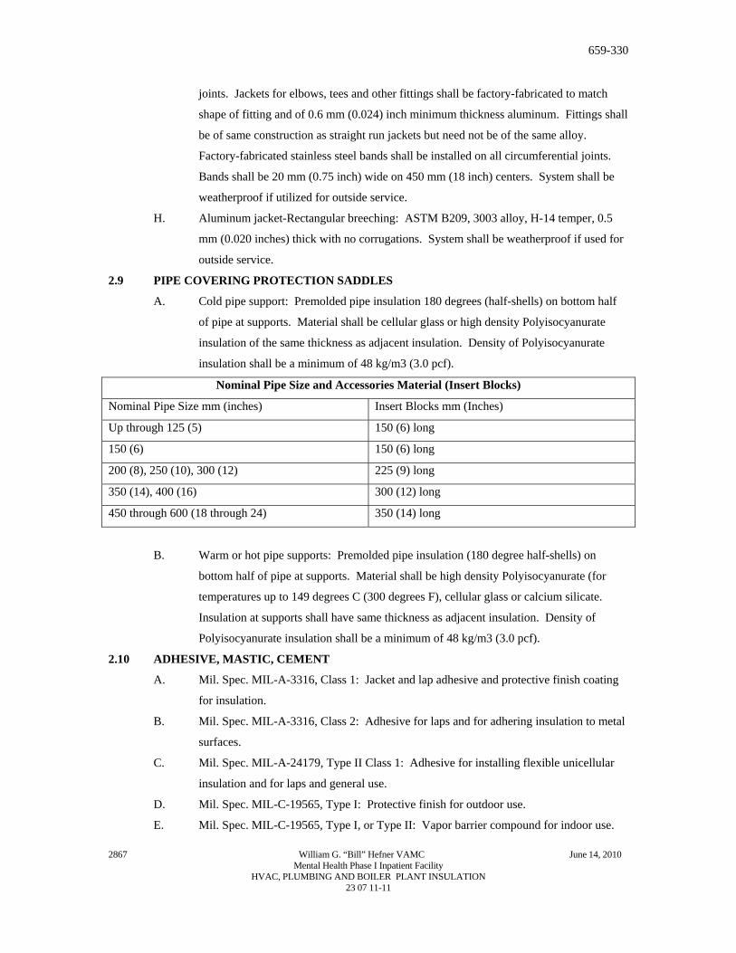
2.9 PIPE COVERING PROTECTION SADDLES
A. Cold pipe support: Premolded pipe insulation 180 degrees (half-shells) on bottom half
of pipe at supports. Material shall be cellular glass or high density Polyisocyanurate
insulation of the same thickness as adjacent insulation. Density of Polyisocyanurate
insulation shall be a minimum of 48 kg/m3 (3.0 pcf).
Nominal Pipe Size and Accessories Material (Insert Blocks)
Nominal Pipe Size mm (inches) Insert Blocks mm (Inches)
Up through 125 (5) 150 (6) long
150 (6) 150 (6) long
200 (8), 250 (10), 300 (12) 225 (9) long
350 (14), 400 (16) 300 (12) long
450 through 600 (18 through 24) 350 (14) long
B. Warm or hot pipe supports: Premolded pipe insulation (180 degree half-shells) on
bottom half of pipe at supports. Material shall be high density Polyisocyanurate (for
temperatures up to 149 degrees C (300 degrees F), cellular glass or calcium silicate.
Insulation at supports shall have same thickness as adjacent insulation. Density of
Polyisocyanurate insulation shall be a minimum of 48 kg/m3 (3.0 pcf).
2.10 ADHESIVE, MASTIC, CEMENT
A. Mil. Spec. MIL-A-3316, Class 1: Jacket and lap adhesive and protective finish coating
for insulation.
B. Mil. Spec. MIL-A-3316, Class 2: Adhesive for laps and for adhering insulation to metal
surfaces.
C. Mil. Spec. MIL-A-24179, Type II Class 1: Adhesive for installing flexible unicellular
insulation and for laps and general use.
D. Mil. Spec. MIL-C-19565, Type I: Protective finish for outdoor use.
E. Mil. Spec. MIL-C-19565, Type I, or Type II: Vapor barrier compound for indoor use.
2867 William G. “Bill” Hefner VAMC June 14, 2010 Mental Health Phase I Inpatient Facility
HVAC, PLUMBING AND BOILER PLANT INSULATION 23 07 11-11
659-330
F. ASTM C449: Mineral fiber hydraulic-setting thermal insulating and finishing cement.
G. Other: Insulation manufacturers’ published recommendations.
2.11 MECHANICAL FASTENERS
A. Pins, anchors: Welded pins, or metal or nylon anchors with tin-coated or fiber washer,
or clips. Pin diameter shall be as recommended by the insulation manufacturer.
B. Staples: Outward clinching monel or stainless steel.
C. Wire: 1.3 mm thick (18 gage) soft annealed galvanized or 1.9 mm (14 gage) copper clad
steel or nickel copper alloy.
D. Bands: 20 mm (3/4 inch) nominal width, brass, galvanized steel, aluminum or stainless
steel.
2.12 REINFORCEMENT AND FINISHES
A. Glass fabric, open weave: ASTM D1668, Type III (resin treated) and Type I (asphalt
treated).
B. Glass fiber fitting tape: Mil. Spec MIL-C-20079, Type II, Class 1.
C. Tape for Flexible Elastomeric Cellular Insulation: As recommended by the insulation
manufacturer.
D. Hexagonal wire netting: 25 mm (one inch) mesh, 0.85 mm thick (22 gage) galvanized
steel.
E. Corner beads: 50 m (2 inch) by 50 mm (2 inch), 0.55 mm thick (26 gage) galvanized
steel; or, 25 mm (1 inch) by 25 mm (1 inch), 0.47 mm thick (28 gage) aluminum angle
adhered to 50 mm (2 inch) by 50 mm (2 inch) Kraft paper.
F. PVC fitting cover: Fed. Spec L-P-535, Composition A, 11-86 Type II, Grade GU, with
Form B Mineral Fiber insert, for media temperature 4 degrees C (40 degrees F) to 121
degrees C (250 degrees F). Below 4 degrees C (40 degrees F) and above 121 degrees C
(250 degrees F). Provide double layer insert. Provide color matching vapor barrier
pressure sensitive tape.
2.13 FIRESTOPPING MATERIAL
Other than pipe and duct insulation, refer to Section 07 84 00 FIRESTOPPING.
2.14 FLAME AND SMOKE
Unless shown otherwise all assembled systems shall meet flame spread 25 and smoke developed
50 rating as developed under ASTM, NFPA and UL standards and specifications. See paragraph
1.3 “Quality Assurance”.
PART 3 – EXECUTION
3.1 GENERAL REQUIREMENTS
2867 William G. “Bill” Hefner VAMC June 14, 2010 Mental Health Phase I Inpatient Facility
A. Required pressure tests of duct and piping joints and connections shall be completed and
the work approved by the COTR for application of insulation. Surface shall be clean
and dry with all foreign materials, such as dirt, oil, loose scale and rust removed.
HVAC, PLUMBING AND BOILER PLANT INSULATION 23 07 11-12
659-330
B. Except for specific exceptions, insulate entire specified equipment, piping (pipe, fittings,
valves, accessories), and duct systems. Insulate each pipe and duct individually. Do not
use scrap pieces of insulation where a full length section will fit.
C. Where removal of insulation of piping, ductwork and equipment is required to comply
with Section 02 82 11, TRADITIONAL ASBESTOS ABATEMENT and Section 02 82
13.13, GLOVEBAG ASBESTOS ABATEMENT, such areas shall be reinsulated to
comply with this specification.
D. Insulation materials shall be installed in a first class manner with smooth and even
surfaces, with jackets and facings drawn tight and smoothly cemented down at all laps.
Insulation shall be continuous through all sleeves and openings, except at fire dampers
and duct heaters (NFPA 90A). Vapor retarders shall be continuous and uninterrupted
throughout systems with operating temperature 16 degrees C (60 degrees F) and below.
Lap and seal vapor barrier over ends and exposed edges of insulation. Anchors, supports
and other metal projections through insulation on cold surfaces shall be insulated and
vapor sealed for a minimum length of 150 mm (6 inches).
E. Install vapor stops at all insulation terminations on either side of valves, pumps and
equipment and particularly in straight lengths of pipe insulation.
F. Construct insulation on parts of equipment such as chilled water pumps and heat
exchangers that must be opened periodically for maintenance or repair, so insulation can
be removed and replaced without damage. Install insulation with bolted 1 mm thick (20
gage) galvanized steel or aluminum covers as complete units, or in sections, with all
necessary supports, and split to coincide with flange/split of the equipment.
G. Insulation on hot piping and equipment shall be terminated square at items not to be
insulated, access openings and nameplates. Cover all exposed raw insulation with white
sealer or jacket material.
H. Protect all insulations outside of buildings with aluminum jacket using lock joint or other
approved system for a continuous weather tight system. Access doors and other items
requiring maintenance or access shall be removable and sealable.
I. HVAC work not to be insulated:
1. Internally insulated air handling units.
2. Relief air ducts (Economizer cycle exhaust air).
3. Exhaust air ducts and plenums, and ventilation exhaust air shafts.
4. Equipment: Expansion tanks, flash tanks, hot water pumps, and steam
condensate pumps.
2867 William G. “Bill” Hefner VAMC June 14, 2010 Mental Health Phase I Inpatient Facility
5. In hot piping: Unions, flexible connectors, control valves, PRVs, safety valves
and discharge vent piping, vacuum breakers, thermostatic vent valves, steam
traps 20 mm (3/4 inch) and smaller, exposed piping through floor for
HVAC, PLUMBING AND BOILER PLANT INSULATION 23 07 11-13
659-330
convectors and radiators. Insulate piping to within approximately 75 mm (3
inches) of insulated items.
J. Plumbing work not to be insulated:
1. Piping and valves of fire protection system.
2. Chromium plated brass piping.
3. Water piping in contact with earth.
4. Piping in pipe basement serving wall hydrants.
5. Small horizontal cold water branch runs in partitions to individual fixtures may
be without insulation for maximum distance of 900 mm (3 feet).
K. Apply insulation materials subject to the manufacturer’s recommended temperature
limits. Apply adhesives, mastic and coatings at the manufacturer’s recommended
minimum coverage.
L. Elbows, flanges and other fittings shall be insulated with the same material as is used o
the pipe straights. The elbow/fitting insulation shall be field-fabricated, mitered or
factory prefabricated to the necessary size and shape to fit on the elbow/fitting. Use of
polyurethane spray-foam to fill a PVC elbow jacket is prohibited on cold applications.
M. Firestop Pipe and Duct insulation:
1. Provide firestopping insulation at fire and smoke barriers through penetrations.
Fire stopping insulation shall be UL listed as defines in Section 07 84 00,
FIRESTOPPING.
2. Pipe and duct penetrations requiring fire stop insulation including, but not
limited to the following:
a. Pipe risers through floors
b. Pipe or duct chase walls and floors
c. Smoke partitions
d. Fire partitions
N. Freeze protection of above grade outdoor piping (over heat tracing tape): 20 mm (0.75)
thick insulation, for all pipe sizes 75 mm (3 inches) and smaller and 25 mm (1 inch)
thick insulation for larger pipes. Provide metal jackets for all pipes. Provide for chilled
water piping as described in Section 23 21 13, HYDRONIC PIPING (electrical heat
tracing systems).
O. Provide metal jackets over insulation as follows:
1. All piping and ducts exposed to outdoor weather.
2. Piping exposed in building, within 1800 mm (6 feet) of the floor, that connects
to sterilizers. Jackets may be applied with pop rivets. Provide aluminum angle
ring escutcheons at wall, ceiling or floor penetrations.
2867 William G. “Bill” Hefner VAMC June 14, 2010 Mental Health Phase I Inpatient Facility
3. A 50 mm (2 inch) overlap is required at longitudinal and circumferential joints.
HVAC, PLUMBING AND BOILER PLANT INSULATION 23 07 11-14
659-330
3.2 INSULATION INSTALLATION
A. Mineral Fiber Board:
1. Faced board: Apply board on pins spaced not more than 300 mm (12 inches)
on center each way, and not less than 75 mm (3 inches) from each edge of
board. In addition to pins, apply insulation bonding adhesive to entire
underside of horizontal metal surfaces. Butt insulation edges tightly and seal
all joints with laps and butt strips. After applying speed clips cut pins off flush
and apply vapor seal patches over clips.
2. Plain board:
a. Insulation shall be scored, beveled or mitered to provide tight joints and
be secured to equipment with bands spaced 225 mm (9 inches) on center
for irregular surfaces or with pins and clips on flat surfaces. Use corner
beads to protect edges of insulation.
b. For hot equipment: Stretch 25 mm (1 inch) mesh wire, with edges wire
laced together, over insulation and finish with insulating and finishing
cement applied in one coat, 6 mm (1/4 inch) thick trowel led to a smooth
finish.
c. For cold equipment: Apply meshed glass fabric in a tack coat 1.5 to 1.7
square meter per liter (60 to 70 square feet per gallon) of vapor mastic
and finish with mastic at 0.3 to 0.4 square meter per liter (12 to 15
square feet per gallon) over the entire fabric surface.
d. Chilled water pumps: Insulate with removable and replaceable 1 mm
thick (20 gage) aluminum or galvanized steel covers lined with
insulation. Seal closure joints/flanges of covers with gasket material.
Fill void space in enclosure with flexible mineral fiber insulation.
3. Exposed, unlined ductwork and equipment in unfinished areas, mechanical and
electrical equipment rooms, and duct work exposed to outdoor weather:
a. 50 mm (2 inch) thick insulation faced with ASJ (white all service
jacket): Supply air duct and afterfilter housing.
b. 40 mm (1-1/2 inch) thick insulation faced with ASJ: Return air duct,
mixed air plenums and prefilter housing.
c. Outside air intake ducts: no insulation required.
4. Cold equipment: 40 mm (1-1/2 inch) thick insulation faced with ASJ.
a. Chilled water pumps, water filter.
5. Hot equipment: 40 mm (1-1/2 inch) thick insulation faced with ASJ.
a. Air separators, steam condensate pump receivers.
2867 William G. “Bill” Hefner VAMC June 14, 2010 Mental Health Phase I Inpatient Facility
HVAC, PLUMBING AND BOILER PLANT INSULATION 23 07 11-15
659-330
b. Reheat coil casing and separation chambers on steam humidifiers
located above ceilings.
c. Domestic water heaters and hot water storage tanks (not factory
insulated).
d. Booster water heaters for dietetics dish and pot washers and for
washdown grease-extracting hoods.
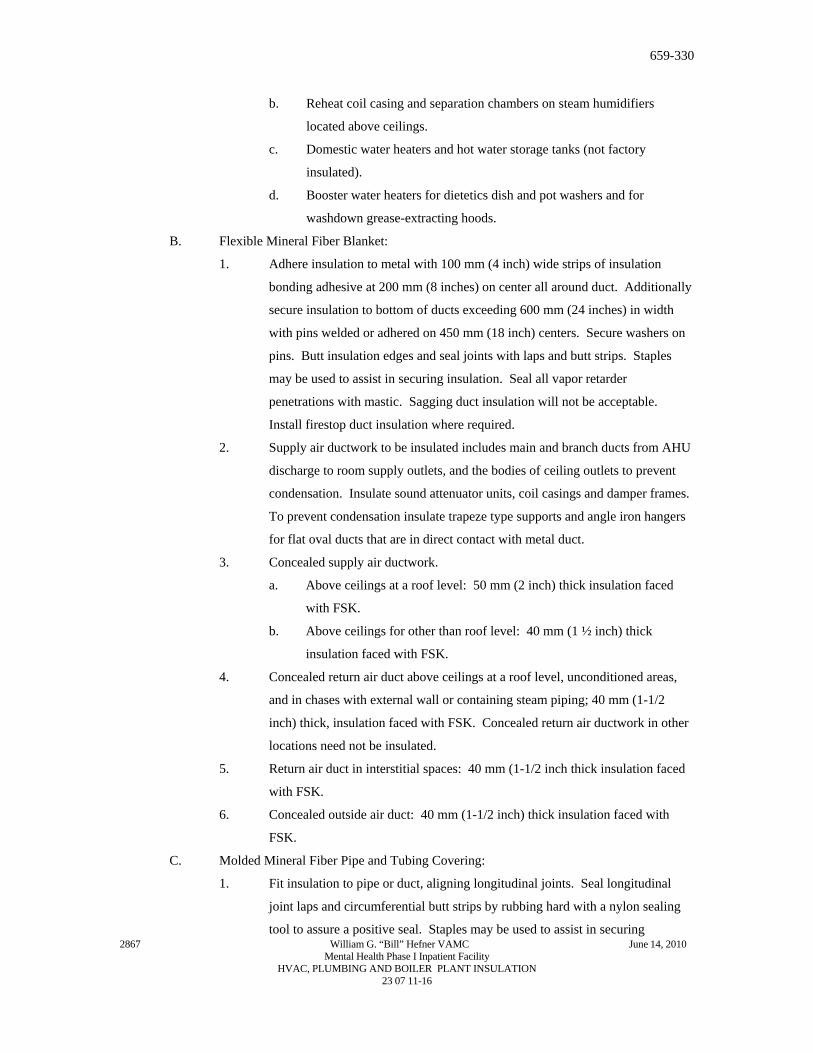
B. Flexible Mineral Fiber Blanket:
1. Adhere insulation to metal with 100 mm (4 inch) wide strips of insulation
bonding adhesive at 200 mm (8 inches) on center all around duct. Additionally
secure insulation to bottom of ducts exceeding 600 mm (24 inches) in width
with pins welded or adhered on 450 mm (18 inch) centers. Secure washers on
pins. Butt insulation edges and seal joints with laps and butt strips. Staples
may be used to assist in securing insulation. Seal all vapor retarder
penetrations with mastic. Sagging duct insulation will not be acceptable.
Install firestop duct insulation where required.
2. Supply air ductwork to be insulated includes main and branch ducts from AHU
discharge to room supply outlets, and the bodies of ceiling outlets to prevent
condensation. Insulate sound attenuator units, coil casings and damper frames.
To prevent condensation insulate trapeze type supports and angle iron hangers
for flat oval ducts that are in direct contact with metal duct.
3. Concealed supply air ductwork.
a. Above ceilings at a roof level: 50 mm (2 inch) thick insulation faced
with FSK.
b. Above ceilings for other than roof level: 40 mm (1 ½ inch) thick
insulation faced with FSK.
4. Concealed return air duct above ceilings at a roof level, unconditioned areas,
and in chases with external wall or containing steam piping; 40 mm (1-1/2
inch) thick, insulation faced with FSK. Concealed return air ductwork in other
locations need not be insulated.
5. Return air duct in interstitial spaces: 40 mm (1-1/2 inch thick insulation faced
with FSK.
6. Concealed outside air duct: 40 mm (1-1/2 inch) thick insulation faced with
FSK.
C. Molded Mineral Fiber Pipe and Tubing Covering:
2867 William G. “Bill” Hefner VAMC June 14, 2010 Mental Health Phase I Inpatient Facility
1. Fit insulation to pipe or duct, aligning longitudinal joints. Seal longitudinal
joint laps and circumferential butt strips by rubbing hard with a nylon sealing
tool to assure a positive seal. Staples may be used to assist in securing
HVAC, PLUMBING AND BOILER PLANT INSULATION 23 07 11-16
659-330
insulation. Seal all vapor retarder penetrations on cold piping with a generous
application of vapor barrier mastic. Provide inserts and install with metal
insulation shields at outside pipe supports. Install freeze protection insulation
over heating cable.
2. Contractor’s options for fitting, flange and valve insulation:
a. Insulating and finishing cement for sizes less than 100 mm (4 inches)
operating at surface temperature of 16 degrees C (61 degrees F) or more.
b. Factory premolded, one piece PVC covers with mineral fiber, (form B),
inserts. Provide two insert layers for pipe temperatures below 4 degrees
C (40 degrees F), or above 121 degrees C (250 degrees F). Secure first
layer of insulation with twine. Seal seam edges with vapor barrier
mastic and secure with fitting tape.
c. Factory molded, ASTM C547 or field mitered sections, joined with
adhesive or wired in place. For hot piping finish with a smoothing coat
of finishing cement. For cold fittings, 16 degrees C (60 degrees F) or
less, vapor seal with a layer of glass fitting tape imbedded between two
2 mm (1/16 inch) coats of vapor barrier mastic.
d. Fitting tape shall extend over the adjacent pipe insulation and overlap on
itself at least 50 mm (2 inches).
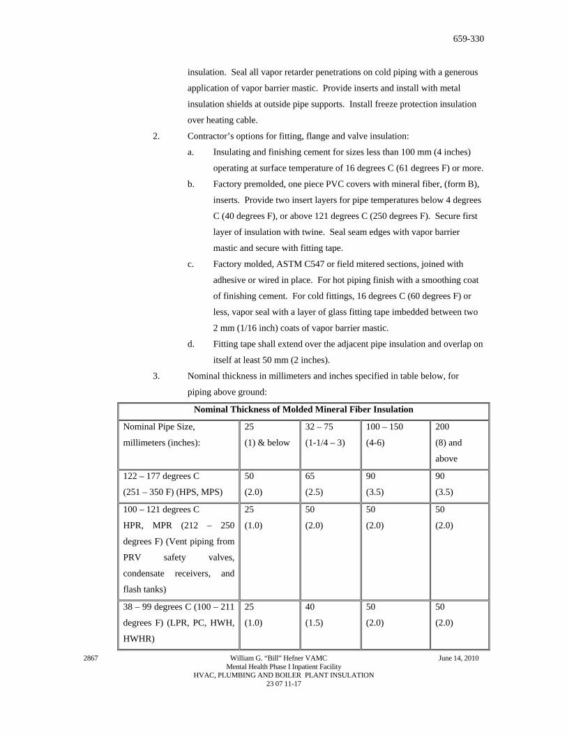
3. Nominal thickness in millimeters and inches specified in table below, for
piping above ground:
Nominal Thickness of Molded Mineral Fiber Insulation
Nominal Pipe Size,
millimeters (inches):
25
(1) & below
32 – 75
(1-1/4 – 3)
100 – 150
(4-6)
200
(8) and
above
122 – 177 degrees C
(251 – 350 F) (HPS, MPS)
50
(2.0)
65
(2.5)
90
(3.5)
90
(3.5)
100 – 121 degrees C
HPR, MPR (212 – 250
degrees F) (Vent piping from
PRV safety valves,
condensate receivers, and
flash tanks)
25
(1.0)
50
(2.0)
50
(2.0)
50
(2.0)
38 – 99 degrees C (100 – 211
degrees F) (LPR, PC, HWH,
HWHR)
25
(1.0)
40
(1.5)
50
(2.0)
50
(2.0)
2867 William G. “Bill” Hefner VAMC June 14, 2010 Mental Health Phase I Inpatient Facility
HVAC, PLUMBING AND BOILER PLANT INSULATION 23 07 11-17
659-330
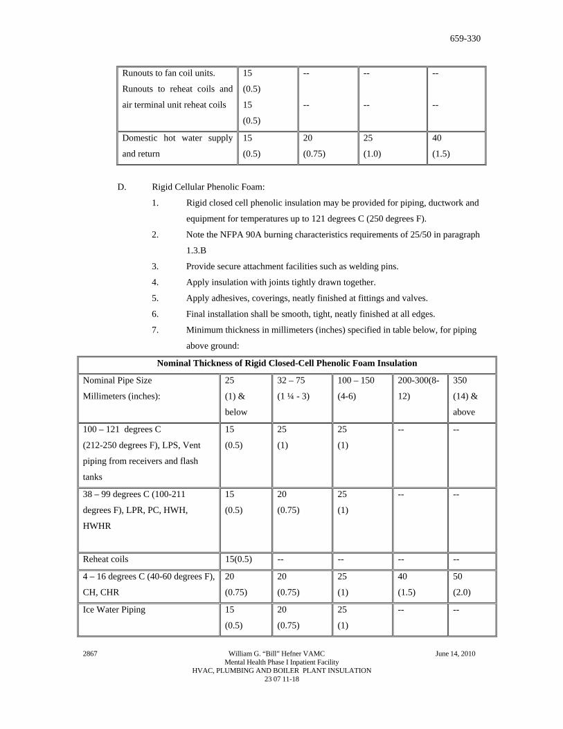
Runouts to fan coil units.
Runouts to reheat coils and
air terminal unit reheat coils
15
(0.5)
15
(0.5)
--
--
--
--
--
--
Domestic hot water supply
and return
15
(0.5)
20
(0.75)
25
(1.0)
40
(1.5)
D. Rigid Cellular Phenolic Foam:
1. Rigid closed cell phenolic insulation may be provided for piping, ductwork and
equipment for temperatures up to 121 degrees C (250 degrees F).
2. Note the NFPA 90A burning characteristics requirements of 25/50 in paragraph
1.3.B
3. Provide secure attachment facilities such as welding pins.
4. Apply insulation with joints tightly drawn together.
5. Apply adhesives, coverings, neatly finished at fittings and valves.
6. Final installation shall be smooth, tight, neatly finished at all edges.
7. Minimum thickness in millimeters (inches) specified in table below, for piping
above ground:
Nominal Thickness of Rigid Closed-Cell Phenolic Foam Insulation
Nominal Pipe Size
Millimeters (inches):
25
(1) &
below
32 – 75
(1 ¼ - 3)
100 – 150
(4-6)
200-300(8-
12)
350
(14) &
above
100 – 121 degrees C
(212-250 degrees F), LPS, Vent
piping from receivers and flash
tanks
15
(0.5)
25
(1)
25
(1)
-- --
38 – 99 degrees C (100-211
degrees F), LPR, PC, HWH,
HWHR
15
(0.5)
20
(0.75)
25
(1)
-- --
Reheat coils 15(0.5) -- -- -- --
4 – 16 degrees C (40-60 degrees F),
CH, CHR
20
(0.75)
20
(0.75)
25
(1)
40
(1.5)
50
(2.0)
Ice Water Piping 15
(0.5)
20
(0.75)
25
(1)
-- --
2867 William G. “Bill” Hefner VAMC June 14, 2010 Mental Health Phase I Inpatient Facility
HVAC, PLUMBING AND BOILER PLANT INSULATION 23 07 11-18
659-330
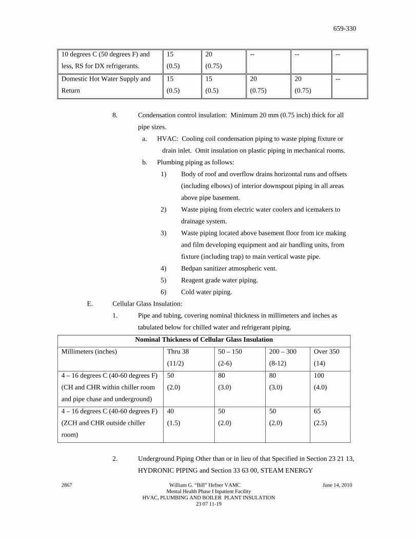
10 degrees C (50 degrees F) and
less, RS for DX refrigerants.
15
(0.5)
20
(0.75)
-- -- --
Domestic Hot Water Supply and
Return
15
(0.5)
15
(0.5)
20
(0.75)
20
(0.75)
--
8. Condensation control insulation: Minimum 20 mm (0.75 inch) thick for all
pipe sizes.
a. HVAC: Cooling coil condensation piping to waste piping fixture or
drain inlet. Omit insulation on plastic piping in mechanical rooms.
b. Plumbing piping as follows:
1) Body of roof and overflow drains horizontal runs and offsets
(including elbows) of interior downspout piping in all areas
above pipe basement.
2) Waste piping from electric water coolers and icemakers to
drainage system.
3) Waste piping located above basement floor from ice making
and film developing equipment and air handling units, from
fixture (including trap) to main vertical waste pipe.
4) Bedpan sanitizer atmospheric vent.
5) Reagent grade water piping.
6) Cold water piping.
E. Cellular Glass Insulation:
1. Pipe and tubing, covering nominal thickness in millimeters and inches as
tabulated below for chilled water and refrigerant piping.
Nominal Thickness of Cellular Glass Insulation
Millimeters (inches) Thru 38
(11/2)
50 – 150
(2-6)
200 – 300
(8-12)
Over 350
(14)
4 – 16 degrees C (40-60 degrees F)
(CH and CHR within chiller room
and pipe chase and underground)
50
(2.0)
80
(3.0)
80
(3.0)
100
(4.0)
4 – 16 degrees C (40-60 degrees F)
(ZCH and CHR outside chiller
room)
40
(1.5)
50
(2.0)
50
(2.0)
65
(2.5)
2. Underground Piping Other than or in lieu of that Specified in Section 23 21 13,
HYDRONIC PIPING and Section 33 63 00, STEAM ENERGY
2867 William G. “Bill” Hefner VAMC June 14, 2010 Mental Health Phase I Inpatient Facility
HVAC, PLUMBING AND BOILER PLANT INSULATION 23 07 11-19
659-330
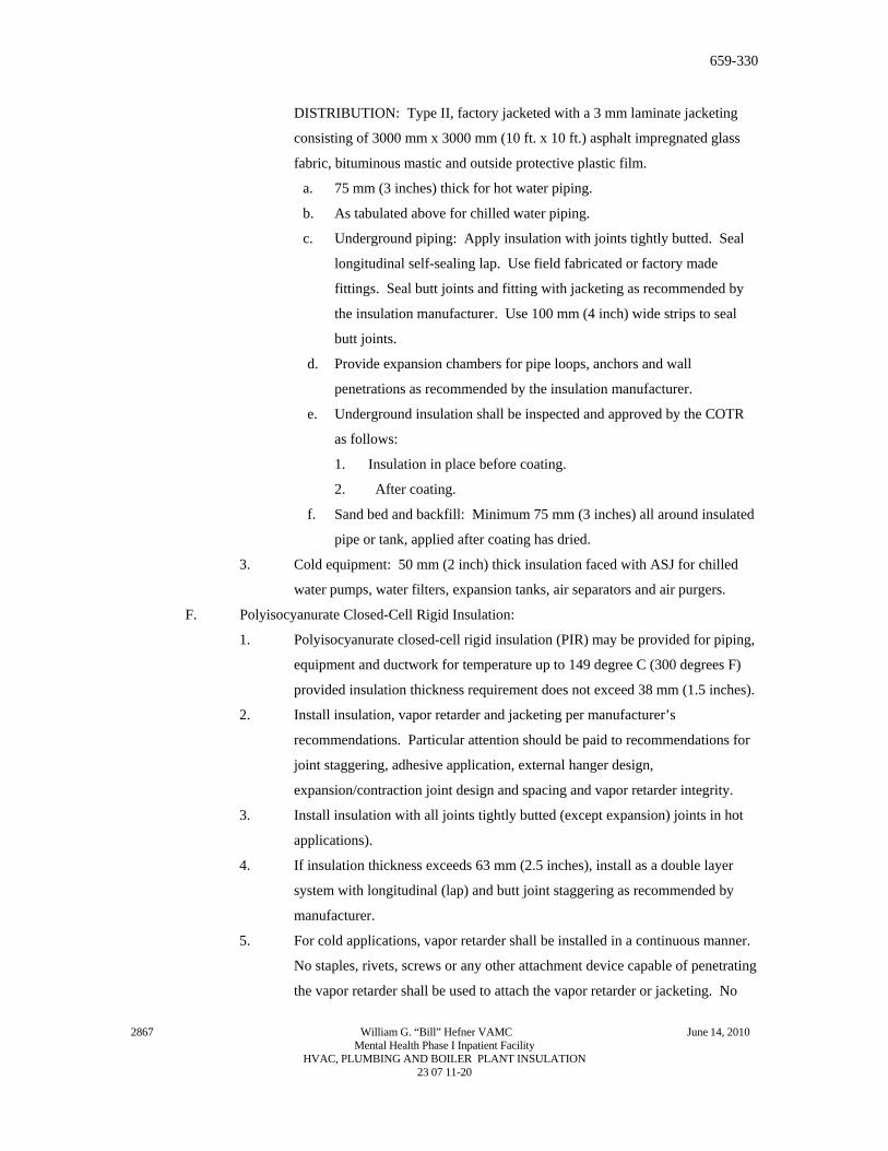
DISTRIBUTION: Type II, factory jacketed with a 3 mm laminate jacketing
consisting of 3000 mm x 3000 mm (10 ft. x 10 ft.) asphalt impregnated glass
fabric, bituminous mastic and outside protective plastic film.
a. 75 mm (3 inches) thick for hot water piping.
b. As tabulated above for chilled water piping.
c. Underground piping: Apply insulation with joints tightly butted. Seal
longitudinal self-sealing lap. Use field fabricated or factory made
fittings. Seal butt joints and fitting with jacketing as recommended by
the insulation manufacturer. Use 100 mm (4 inch) wide strips to seal
butt joints.
d. Provide expansion chambers for pipe loops, anchors and wall
penetrations as recommended by the insulation manufacturer.
e. Underground insulation shall be inspected and approved by the COTR
as follows:
1. Insulation in place before coating.
2. After coating.
f. Sand bed and backfill: Minimum 75 mm (3 inches) all around insulated
pipe or tank, applied after coating has dried.
3. Cold equipment: 50 mm (2 inch) thick insulation faced with ASJ for chilled
water pumps, water filters, expansion tanks, air separators and air purgers.
F. Polyisocyanurate Closed-Cell Rigid Insulation:
1. Polyisocyanurate closed-cell rigid insulation (PIR) may be provided for piping,
equipment and ductwork for temperature up to 149 degree C (300 degrees F)
provided insulation thickness requirement does not exceed 38 mm (1.5 inches).
2. Install insulation, vapor retarder and jacketing per manufacturer’s
recommendations. Particular attention should be paid to recommendations for
joint staggering, adhesive application, external hanger design,
expansion/contraction joint design and spacing and vapor retarder integrity.
3. Install insulation with all joints tightly butted (except expansion) joints in hot
applications).
4. If insulation thickness exceeds 63 mm (2.5 inches), install as a double layer
system with longitudinal (lap) and butt joint staggering as recommended by
manufacturer.
5. For cold applications, vapor retarder shall be installed in a continuous manner.
No staples, rivets, screws or any other attachment device capable of penetrating
the vapor retarder shall be used to attach the vapor retarder or jacketing. No
2867 William G. “Bill” Hefner VAMC June 14, 2010 Mental Health Phase I Inpatient Facility
HVAC, PLUMBING AND BOILER PLANT INSULATION 23 07 11-20
659-330
wire ties capable of penetrating the vapor retarder shall be used to hold the
insulation in place. Banding shall be used to attach PVC or metal jacketing.
6. Elbows, flanges and other fittings shall be insulated with the same material as
is used on the pipe straights. The elbow/fitting insulation shall be field-
fabricated, mitered or factory prefabricated to the necessary size and shape to
fit on the elbow/fitting. Use of polyurethane spray-foam to fill PVC elbow
jacket is prohibited on cold applications.
7. For cold applications, the vapor retarder on elbows/fittings shall be either
mastic-fabric-mastic or 2 mil thick PVDC vapor retarder adhesive tape.
8. All PVC and metal jacketing shall be installed so as to naturally shed water.
Joints shall point down and shall be sealed with either adhesive or caulking
(except for periodic slip joints).
9. Underground piping: Follow instructions for above ground piping but the
vapor retarder jacketing shall be 6 mil thick PVDC or minimum 30 mil thick
rubberized bituminous membrane. Sand bed and backfill shall be a minimum
of 150 mm (6 inches) all around insulated pipe.
10. Note the NFPA 90A burning characteristic requirements of 25/50 in paragraph
1.3B. Refer to paragraph 3.1 for items not to be insulated.
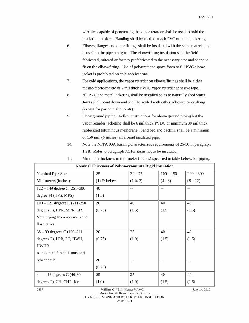
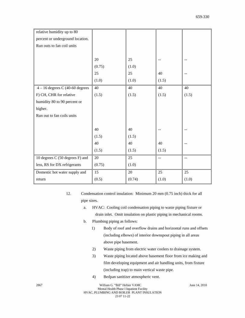
11. Minimum thickness in millimeter (inches) specified in table below, for piping:
Nominal Thickness of Polyisocyanurate Rigid Insulation
Nominal Pipe Size
Millimeters (inches):
25
(1) & below
32 – 75
(1 ¼-3)
100 – 150
(4 - 6)
200 – 300
(8 – 12)
122 – 149 degree C (251–300
degree F) (HPS, MPS)
40
(1.5)
-- -- --
100 – 121 degrees C (211-250
degrees F), HPR, MPR, LPS,
Vent piping from receivers and
flash tanks
20
(0.75)
40
(1.5)
40
(1.5)
40
(1.5)
38 – 99 degrees C (100–211
degrees F), LPR, PC, HWH,
HWHR
Run outs to fan coil units and
reheat coils
20
(0.75)
20
(0.75)
25
(1.0)
--
40
(1.5)
--
40
(1.5)
--
4 – 16 degrees C (40-60
degrees F), CH, CHR, for
25
(1.0)
25
(1.0)
40
(1.5)
40
(1.5)
2867 William G. “Bill” Hefner VAMC June 14, 2010 Mental Health Phase I Inpatient Facility
HVAC, PLUMBING AND BOILER PLANT INSULATION 23 07 11-21
659-330
relative humidity up to 80
percent or underground location.
Run outs to fan coil units
20
(0.75)
25
(1.0)
25
(1.0)
25
(1.0)
--
40
(1.5)
--
--
4 – 16 degrees C (40-60 degrees
F) CH, CHR for relative
humidity 80 to 90 percent or
higher.
Run out to fan coils units
40
(1.5)
40
(1.5)
40
(1.5)
40
(1.5)
40
(1.5)
40
(1.5)
40
(1.5)
--
40
(1.5)
40
(1.5)
--
--
10 degrees C (50 degrees F) and
less, RS for DX refrigerants
20
(0.75)
25
(1.0)
-- --
Domestic hot water supply and
return
15
(0.5)
20
(0.74)
25
(1.0)
25
(1.0)
12. Condensation control insulation: Minimum 20 mm (0.75 inch) thick for all
pipe sizes.
a. HVAC: Cooling coil condensation piping to waste piping fixture or
drain inlet. Omit insulation on plastic piping in mechanical rooms.
b. Plumbing piping as follows:
1) Body of roof and overflow drains and horizontal runs and offsets
(including elbows) of interior downspout piping in all areas
above pipe basement.
2) Waste piping from electric water coolers to drainage system.
3) Waste piping located above basement floor from ice making and
film developing equipment and air handling units, from fixture
(including trap) to main vertical waste pipe.
4) Bedpan sanitizer atmospheric vent.
2867 William G. “Bill” Hefner VAMC June 14, 2010 Mental Health Phase I Inpatient Facility
HVAC, PLUMBING AND BOILER PLANT INSULATION 23 07 11-22
659-330
5) Reagent grade water piping.
6) Cold Water Piping.
G. Flexible Elastomeric Cellular Thermal Insulation:
1. Apply insulation and fabricate fittings in accordance with the manufacturer’s
installation instructions and finish with two coats of weather resistant finish as
recommended by the insulation manufacturer.
2. Pipe and Tubing insulation:
a. Use proper size material. Do not stretch or strain insulation.
b. To avoid undue compression of insulation, provide cork stoppers or
wood inserts at supports as recommended by the insulation
manufacturer. Insulation shields are specified under Section 23 05 11,
COMMON WORK RESULTS FOR HVAC AND STEAM
GENERATION.
c. Where possible, slip insulation over the pipe or tubing prior to
connection, and seal the butt joints with adhesive. Where the slip-on
technique is not possible, slit the insulation and apply it to the pipe
sealing the seam and joints with contact adhesive. Optional tape
sealing, as recommended by the manufacturer, may be employed. Make
changes from mineral fiber insulation in a straight run of pipe, not at a
fitting. Seal joint with tape.
3. Apply sheet insulation to flat or large curved surfaces with 100 percent
adhesive coverage. For fittings and large pipe, apply adhesive to seams only.
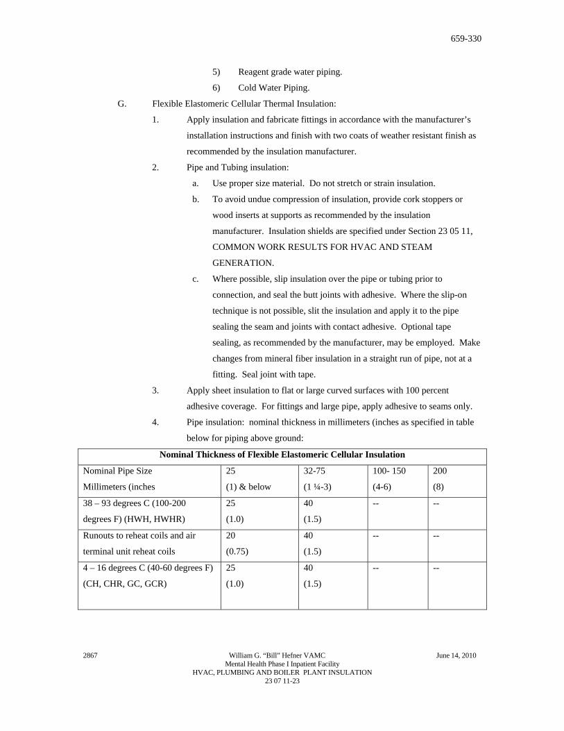
4. Pipe insulation: nominal thickness in millimeters (inches as specified in table
below for piping above ground:
Nominal Thickness of Flexible Elastomeric Cellular Insulation
Nominal Pipe Size
Millimeters (inches
25
(1) & below
32-75
(1 ¼-3)
100- 150
(4-6)
200
(8)
38 – 93 degrees C (100-200
degrees F) (HWH, HWHR)
25
(1.0)
40
(1.5)
-- --
Runouts to reheat coils and air
terminal unit reheat coils
20
(0.75)
40
(1.5)
-- --
4 – 16 degrees C (40-60 degrees F)
(CH, CHR, GC, GCR)
25
(1.0)
40
(1.5)
-- --
2867 William G. “Bill” Hefner VAMC June 14, 2010 Mental Health Phase I Inpatient Facility
HVAC, PLUMBING AND BOILER PLANT INSULATION 23 07 11-23
659-330
20
(0.75)
40
(1.5)
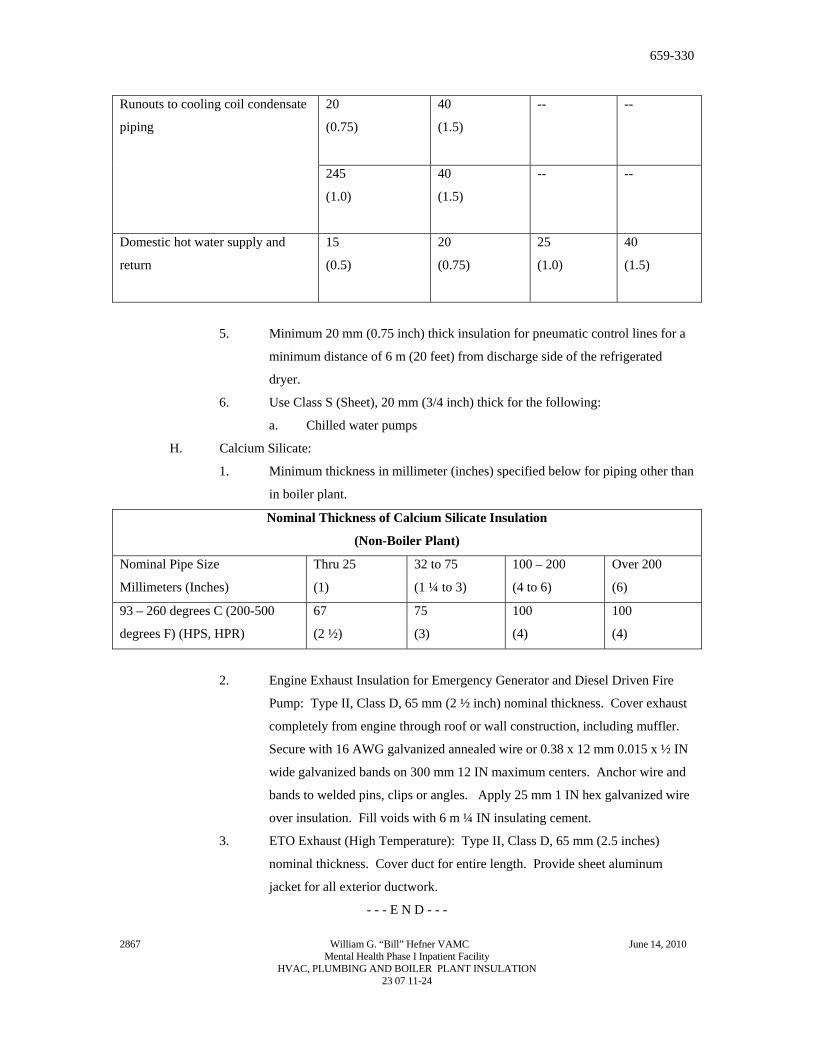
-- -- Runouts to cooling coil condensate
piping
245
(1.0)
40
(1.5)
-- --
Domestic hot water supply and
return
15
(0.5)
20
(0.75)
25
(1.0)
40
(1.5)
5. Minimum 20 mm (0.75 inch) thick insulation for pneumatic control lines for a
minimum distance of 6 m (20 feet) from discharge side of the refrigerated
dryer.
6. Use Class S (Sheet), 20 mm (3/4 inch) thick for the following:
a. Chilled water pumps
H. Calcium Silicate:
1. Minimum thickness in millimeter (inches) specified below for piping other than
in boiler plant.
Nominal Thickness of Calcium Silicate Insulation
(Non-Boiler Plant)
Nominal Pipe Size
Millimeters (Inches)
Thru 25
(1)
32 to 75
(1 ¼ to 3)
100 – 200
(4 to 6)
Over 200
(6)
93 – 260 degrees C (200-500
degrees F) (HPS, HPR)
67
(2 ½)
75
(3)
100
(4)
100
(4)
2. Engine Exhaust Insulation for Emergency Generator and Diesel Driven Fire
Pump: Type II, Class D, 65 mm (2 ½ inch) nominal thickness. Cover exhaust
completely from engine through roof or wall construction, including muffler.
Secure with 16 AWG galvanized annealed wire or 0.38 x 12 mm 0.015 x ½ IN
wide galvanized bands on 300 mm 12 IN maximum centers. Anchor wire and
bands to welded pins, clips or angles. Apply 25 mm 1 IN hex galvanized wire
over insulation. Fill voids with 6 m ¼ IN insulating cement.
3. ETO Exhaust (High Temperature): Type II, Class D, 65 mm (2.5 inches)
nominal thickness. Cover duct for entire length. Provide sheet aluminum
jacket for all exterior ductwork.
- - - E N D - - -
2867 William G. “Bill” Hefner VAMC June 14, 2010 Mental Health Phase I Inpatient Facility
HVAC, PLUMBING AND BOILER PLANT INSULATION 23 07 11-24