Embed Size (px)
Citation preview

NC Department of Administration NC State Veterans Home Salisbury Renovation and Addition- FAI 37-012
SCO ID#: 15-12572-01A March 20, 2017
COMMON WORK RESULTS FOR PLUMBING 220500 - 1
SECTION 220500 - COMMON WORK RESULTS FOR PLUMBING
PART 1 - GENERAL
1.1 SUMMARY
A. This Section includes the following:
1. Piping materials and installation instructions common to most piping systems. 2. Dielectric fittings. 3. Mechanical sleeve seals. 4. Sleeves. 5. Escutcheons. 6. Grout. 7. Plumbing demolition. 8. Equipment installation requirements common to equipment sections. 9. Concrete bases. 10. Supports and anchorages.
1.2 DEFINITIONS
A. Finished Spaces: Spaces other than plumbing and electrical equipment rooms, furred spaces, pipe chases, unheated spaces immediately below roof, spaces above ceilings, unexcavated spaces, crawlspaces, and tunnels.
B. Exposed, Interior Installations: Exposed to view indoors. Examples include finished occupied spaces and plumbing equipment rooms.
C. Exposed, Exterior Installations: Exposed to view outdoors or subject to outdoor ambient temperatures and weather conditions. Examples include rooftop locations.
D. Concealed, Interior Installations: Concealed from view and protected from physical contact by building occupants. Examples include above ceilings and in chases.
E. Concealed, Exterior Installations: Concealed from view and protected from weather conditions and physical contact by building occupants but subject to outdoor ambient temperatures. Examples include installations within unheated shelters.
1.3 QUALITY ASSURANCE
A. Electrical Characteristics for Plumbing Equipment: Equipment of higher electrical characteristics may be furnished provided such proposed equipment is approved in writing and connecting electrical services, circuit breakers, and conduit sizes are appropriately modified. If minimum energy ratings or efficiencies are specified, equipment shall comply with requirements.

NC Department of Administration NC State Veterans Home Salisbury Renovation and Addition- FAI 37-012
SCO ID#: 15-12572-01A March 20, 2017
COMMON WORK RESULTS FOR PLUMBING 220500 - 2
1.4 COORDINATION DRAWINGS: The ceiling space is very limited. Coordination of the existing conditions as well as coordination of the new elements to be installed must be coordinated among the various trades. The Mechanical subcon-tractor will have the primary coordination responsibility due to the space requirements of ductwork, piping, control terminals and other ceiling elements. Plumbing, electrical, and fire protection subcon-tractors are required to cooperate with the mechanical subcontractor and provide coordination draw-ings of their respective trades to the mechanical subcontractor for inclusion. Prepare coordination draw-ings to a scale of 1/4" = 1' - 0" or larger, detailing major elements, components, and systems of mechani-cal equipment and materials in relationship with other systems, installations, and building components. Indicate locations where space is limited for installation and access and where sequencing and coordi-nation of installations are of importance to the efficient flow of the Work, including (but not necessarily limited to) the following:
1. Planned piping layout, including valve and specialty locations and valve-stem movement. 2. Clearances for servicing and maintaining equipment, accessories, and specialties,
including space for disassembly required for periodic maintenance. 3. Equipment and accessory service connections and support details. 4. Fire-rated wall and floor penetrations. (Highlight fire and smoke partitions) 5. Floor plans, elevations, sections, and details to indicate location of pipes, ducts, ets. 6. Roof curbs and openings 7. Access doors and panels 8. Reflected ceiling plans to coordinate and integrate installation of air outlets and inlets,
light fixtures, communication system components, sprinklers, and other ceiling-mounted items.
9. Complete air distribution including ductwork, terminals, grilles diffusers, dampers, etc 10. Chilled water, hot water, , steam supply and return, including valves, coils, meters,
gauges, etc 11. Roof drains and associated piping, sanitary waste and vent piping, domestic hot and cold
water piping. 12. Fire sprinkler and standpipe system. 13. Drawings will be coordinated amongst all pertinent prime and subcontractors prior to
review and approval by General Contractor. A copy of the approved coordinated drawing(s) shall be sent to the architect for record purpose
1.5 COORDINATION OF TRADES
A. Check, verify and coordinate work with other trades. Include modifications, relocations or adjustments necessary to complete work or to avoid interference with the building structure or other trades.
B. Drawings and specifications are necessarily schematic in nature and cannot describe completely all situations that might be encountered in the field. It is the responsibility of the contractor to familiarize himself with the scope of work required and include all work indicated or reasonably implied by the contract documents.
C. Layout the work to prevent conflict with, and to co-ordinate with work of other trades. Systems shall generally be run in a rectilinear fashion.
D. Each trade is responsible for the coordination of their work with all other work at the site prior to beginning in each area.

NC Department of Administration NC State Veterans Home Salisbury Renovation and Addition- FAI 37-012
SCO ID#: 15-12572-01A March 20, 2017
COMMON WORK RESULTS FOR PLUMBING 220500 - 3
E. Coordinate scheduling, submittals, and work of the various sections of the Project Manual to ensure efficient and orderly sequence of installation of interdependent construction elements, with provisions for accommodating items installed later.
F. Verify utility requirements and characteristics of operating equipment are compatible with building utilities. Coordinate work of various sections having interdependent responsibilities for installing, connecting to, and placing in service, such equipment.
G. Coordinating space requirements, supports, and installation of mechanical and electrical work which are indicated diagrammatically on Drawings. Follow routing shown for pipes, ducts, and conduit, as closely as practicable; place runs parallel with lines of building. Utilize spaces effi-ciently to maximize accessibility for other installations, for maintenance, and for repairs.
H. In finished areas except as otherwise indicated, conceal pipes, ducts, and wiring within the con-struction. Coordinate locations of fixtures and outlets with finish elements.
1.6 SEQUENCING AND SCHEDULING
A. Coordinate mechanical equipment installation with other building components.
B. Arrange for pipe spaces, chases, slots, and openings in building structure during progress of construction to allow for mechanical installations.
C. Coordinate installation of required supporting devices and set sleeves in poured-in-place concrete and other structural components, as they are constructed.
D. Sequence, coordinate, and integrate installations of mechanical materials and equipment for efficient flow of the Work. Coordinate installation of large equipment requiring positioning before closing in building.
E. Coordinate connection of mechanical systems with exterior underground and overhead utilities and services. Comply with requirements of governing regulations, franchised service companies, and controlling agencies.
F. Coordinate requirements for access panels and doors if mechanical items requiring access are concealed behind finished surfaces. Access panels and doors are specified in Division 8 Section "Access Doors."
G. Coordinate installation of identifying devices after completing covering and painting, if devices are applied to surfaces. Install identifying devices before installing acoustical ceilings and similar concealment.
1.7 DIVISION OF WORK (Division 22/26)
A. This section delineates the division of work between Division 22 and Division 26.
NC Department of Administration NC State Veterans Home Salisbury Renovation and Addition- FAI 37-012
SCO ID#: 15-12572-01A March 20, 2017
COMMON WORK RESULTS FOR PLUMBING 220500 - 4
B. Specific work to be done under Division 26 is hereinafter listed or described. All other work necessary for the operation of Division 22 equipment shall be performed under Division 22.
C. All individual motor starters for mechanical equipment (pumps, etc.) shall be furnished and installed under Division 22 unless indicated as a part of a motor control center. Motor starters for mechanical equipment provided in motor control centers shall be furnished under Division 26.
D. Under Division 26, power wiring shall be provided up to a termination point consisting of a junction box, trough, starter or disconnect switch. Under Division 26 line side terminations shall be provided. Wiring from the termination point to the mechanical equipment, including final connections, shall be provided under Division 22.
E. All relays, actuators, timers, seven-day clocks, alternators, pressure, vacuum, float, flow, pneumatic-electric, and electric-pneumatic switches, aquastats, freezestats, line and low volt-age thermostats, thermals, remote selector switches, remote pushbutton stations, emergency break-glass stations, interlocking, disconnect switches beyond termination point, and other appurtenances associated with equipment under Division 22 shall be furnished, installed and wired under Division 22.
F. All wiring required for controls and instrumentation not indicated on the drawings shall be furnished and installed by Division 22.
G. Where electrical wiring is required by trades other than covered by Division 26, specifica-tions for that section shall refer to same wiring materials and methods as specified under Di-vision 26. No Exceptions.
PART 2 - PRODUCTS
2.1 PIPE, TUBE, AND FITTINGS
A. Refer to individual Division 22 piping Sections for pipe, tube, and fitting materials and joining methods.
2.2 JOINING MATERIALS
A. Refer to individual Division 22 piping Sections for special joining materials not listed below.
2.3 DIELECTRIC FITTINGS
A. Description: Combination fitting of copper alloy and ferrous materials with threaded, solder-joint, plain, or weld-neck end connections that match piping system materials.
B. Insulating Material: Suitable for system fluid, pressure, and temperature.

NC Department of Administration NC State Veterans Home Salisbury Renovation and Addition- FAI 37-012
SCO ID#: 15-12572-01A March 20, 2017
COMMON WORK RESULTS FOR PLUMBING 220500 - 5
C. Dielectric Unions: Factory-fabricated, union assembly, for 250-psig minimum working pressure at 180 deg F.
D. Dielectric Flanges: Factory-fabricated, companion-flange assembly, for 150- or 300-psig minimum working pressure as required to suit system pressures.
E. Dielectric Couplings: Galvanized-steel coupling with inert and noncorrosive, thermoplastic lining; threaded ends; and 300-psig minimum working pressure at 225 deg F.
F. Dielectric Nipples: Electroplated steel nipple with inert and noncorrosive, thermoplastic lining; plain, threaded, or grooved ends; and 300-psig minimum working pressure at 225 deg F.
2.4 MECHANICAL SLEEVE SEALS
A. Description: Modular sealing element unit, designed for field assembly, to fill annular space between pipe and sleeve.
2.5 SLEEVES
A. Steel Pipe for pipe penetrations: ASTM A 53, Type E, Grade B, Schedule 40, galvanized, plain ends.
B. Cast Iron: Cast or fabricated "wall pipe" equivalent to ductile-iron pressure pipe, with plain ends and integral waterstop, unless otherwise indicated.
C. Stack Sleeve Fittings: Manufactured, cast-iron sleeve with integral clamping flange. Include clamping ring and bolts and nuts for membrane flashing.
D. Sleeves shall be installed for all pipe penetrations of floor slabs above grade. Tops of sleeves shall extend 2” above the floor.
2.6 ESCUTCHEONS
A. Description: Manufactured wall and ceiling escutcheons and floor plates, with an ID to closely fit around pipe, tube, and insulation of insulated piping and an OD that completely covers opening.
2.7 ACCESS PANELS AND DOORS
A. Provide access panels and doors to match the wall or ceiling construction.
B. Access panels shall be installed where necessary for access to valves or similar devices requiring routine access.

NC Department of Administration NC State Veterans Home Salisbury Renovation and Addition- FAI 37-012
SCO ID#: 15-12572-01A March 20, 2017
COMMON WORK RESULTS FOR PLUMBING 220500 - 6
PART 3 - EXECUTION
3.1 PLUMBING DEMOLITION
A. Refer to Division 01 Section "Cutting and Patching" and Division 02 Section "Selective Structure Demolition" for general demolition requirements and procedures.
B. Disconnect, demolish, and remove plumbing systems, equipment, and components indicated to be removed.
1. Piping to Be Removed: Remove portion of piping indicated to be removed and cap or plug remaining piping with same or compatible piping material.
2. Piping to Be Abandoned in Place: Do not abandon “dead” piping in place. Remove all piping that is to become inactive or not in service.
3. Equipment to Be Removed: Disconnect and cap services and remove equipment. 4. Equipment to Be Removed and Reinstalled: Disconnect and cap services and remove,
clean, and store equipment; when appropriate, reinstall, reconnect, and make equipment operational.
5. Equipment to Be Removed and Salvaged: Disconnect and cap services and remove equipment and deliver to Owner.
6. Do not abandon any equipment in place
C. If pipe, insulation, or equipment to remain is damaged in appearance or is unserviceable, remove damaged or unserviceable portions and replace with new products of equal capacity and quality.
3.2 PIPING SYSTEMS - COMMON REQUIREMENTS
A. Install piping according to the following requirements and Division 22 Sections specifying piping systems.
B. Drawing plans, schematics, and diagrams indicate general location and arrangement of piping systems. Indicated locations and arrangements were used to size pipe and calculate friction loss, expansion, pump sizing, and other design considerations. Install piping as indicated unless deviations to layout are approved on Coordination Drawings.
C. Install piping in concealed locations, unless otherwise indicated and except in equipment rooms and service areas.
D. Install piping indicated to be exposed and piping in equipment rooms and service areas at right angles or parallel to building walls. Diagonal runs are prohibited unless specifically indicated otherwise.
E. Install piping above accessible ceilings to allow sufficient space for ceiling panel removal.
F. Install piping to permit valve servicing.
G. Install piping at indicated slopes.

NC Department of Administration NC State Veterans Home Salisbury Renovation and Addition- FAI 37-012
SCO ID#: 15-12572-01A March 20, 2017
COMMON WORK RESULTS FOR PLUMBING 220500 - 7
H. Install escutcheons for penetrations of walls, ceilings, and floors.
I. Install sleeves for pipes passing through concrete and masonry walls, gypsum-board partitions, and concrete floor and roof slabs.
J. Aboveground, Exterior-Wall Pipe Penetrations: Seal penetrations using sleeves and mechanical sleeve seals. Select sleeve size to allow for 1-inch annular clear space between pipe and sleeve for installing mechanical sleeve seals.
K. Underground, Exterior-Wall Pipe Penetrations: Install cast-iron "wall pipes" for sleeves. Seal pipe penetrations using mechanical sleeve seals. Select sleeve size to allow for 1-inch annular clear space between pipe and sleeve for installing mechanical sleeve seals.
L. Fire-Barrier Penetrations: Maintain indicated fire rating of walls, partitions, ceilings, and floors at pipe penetrations. Seal pipe penetrations with firestop materials. Refer to Division 07 Section "Penetration Firestopping" for materials.
3.3 PIPING JOINT CONSTRUCTION
A. Join pipe and fittings according to Division 22 Sections specifying piping systems.
3.4 PIPING CONNECTIONS
A. Make connections according to the following, unless otherwise indicated:
1. Install unions, in piping NPS 2 and smaller, adjacent to each valve and at final connection to each piece of equipment.
2. Install flanges, in piping NPS 2-1/2 and larger, adjacent to flanged valves and at final connection to each piece of equipment.
3. Dry Piping Systems: Install dielectric unions and flanges to connect piping materials of dissimilar metals.
4. Wet Piping Systems: Install dielectric coupling and nipple fittings to connect piping materials of dissimilar metals.
3.5 EQUIPMENT INSTALLATION - COMMON REQUIREMENTS
A. Install equipment to allow maximum possible headroom unless specific mounting heights are not indicated.
B. Install equipment level and plumb, parallel and perpendicular to other building systems and components in exposed interior spaces, unless otherwise indicated.
C. Install plumbing equipment to facilitate service, maintenance, and repair or replacement of components. Connect equipment for ease of disconnecting, with minimum interference to other installations. Extend grease fittings to accessible locations.
D. Install equipment to allow right of way for piping installed at required slope.
NC Department of Administration NC State Veterans Home Salisbury Renovation and Addition- FAI 37-012
SCO ID#: 15-12572-01A March 20, 2017
COMMON WORK RESULTS FOR PLUMBING 220500 - 8
3.6 CONCRETE BASES
A. Concrete Bases: Anchor equipment to concrete base according to equipment manufacturer's written instructions and according to seismic codes at Project.
1. Construct concrete bases of dimensions indicated, but not less than 4 inches larger in both directions than supported unit.
3.7 CUTTING AND PATCHING
A. Cut, channel, chase, and drill floors, walls, partitions, ceilings, and other surfaces necessary for mechanical installations. Perform cutting by skilled mechanics of trades involved.
B. Repair cut surfaces to match adjacent surfaces. Execute cutting and patching including excava-tion and fill to complete the work, to uncover work to install improperly sequenced work, to remove and replace defective or non-conforming work, to remove samples of installed work for testing when requested, to provide openings in the work for penetration of mechanical and elec-trical work, to execute patching to complement adjacent work, and to fit Products together to integrate with other work.
C. Execute work by methods to avoid damage to other work, and which will provide appropriate surfaces to receive patching and finishing. In existing work, minimize damage and restore to original condition.
D. Employ original installer to perform cutting for weather exposed and moisture resistant elements, and sight exposed surfaces.
E. Cut rigid materials using masonry saw or core drill. Pneumatic tools not allowed with-out prior approval.
F. Restore work with new Products in accordance with requirements of Contract Documents.
G. Fit work air tight to pipes, sleeves, ducts, conduit, and other penetrations through sur-faces.
H. At penetrations of fire rated walls, partitions, ceiling, or floor construction, completely seal voids with fire rated material, to full thickness of the penetrated element.
I. Refinish surfaces to match adjacent finish. For continuous surfaces, refinish to nearest intersec-tion or natural break. For an assembly, refinish entire unit.
END OF SECTION 220500

NC Department of Administration NC State Veterans Home Salisbury Renovation and Addition- FAI 37-012
SCO ID#: 15-12572-01A March 20, 2017
PIPE TESTING 220500 - 1
SECTION 220510 – PIPE TESTING
PART 1 - GENERAL
1.1 SUMMARY
A. This Section includes the following:
1. Pressure testing of piping systems.
PART 2 - PRODUCTS (NOT USED)
PART 3 - EXECUTION
3.1 PIPE TESTING
A. Test all piping as specified herein. Test results shall demonstrate no leaks or appreciable loss of pressure. Repair or replace defective piping until tests are accomplished successfully.
B. All nitrogen used for testing shall be oil-free dry nitrogen.
C. All air used for testing shall be clean, dry, and oil-free.
D. All piping systems shall be cleaned after testing
E. System Pressure Medium Duration Hot & Cold water (domestic) 150 psig water 4 hours Waste & vent 10 feet water 4 hours
END OF SECTION 220510

THIS PAGE INTENTIONALLY LEFT BLANK

NC Department of Administration NC State Veterans Home Salisbury Renovation and Addition- FAI 37-012
SCO ID#: 15-12572-01A March 20, 2017
GENERAL-DUTY VALVES FOR PLUMBING PIPING 220523 - 1
SECTION 220523 - GENERAL-DUTY VALVES FOR PLUMBING PIPING
PART 1 - GENERAL
1.1 SUMMARY
A. Section Includes:
1. Brass ball valves. 2. Bronze ball valves. 3. Bronze swing check valves. 4. Bronze gate valves.
B. Related Sections:
1. Division 22 plumbing piping Sections for specialty valves applicable to those Sections only.
2. Division 22 Section "Identification for Plumbing Piping and Equipment" for valve tags and schedules.
3. Division 33 water distribution piping Sections for general-duty and specialty valves for site construction piping.
1.2 SUBMITTALS
A. Product Data: For each type of valve indicated.
1.3 QUALITY ASSURANCE
A. ASME Compliance: ASME B16.10 and ASME B16.34 for ferrous valve dimensions and design criteria.
B. NSF Compliance: NSF 61 for valve materials for potable-water service.
PART 2 - PRODUCTS
2.1 GENERAL REQUIREMENTS FOR VALVES
A. Refer to valve schedule articles for applications of valves.
B. Valve Pressure and Temperature Ratings: Not less than indicated and as required for system pressures and temperatures, 200 psi CWP minimum.
C. Valve Sizes: Same as upstream piping unless otherwise indicated.
D. Valve Actuator Types:

NC Department of Administration NC State Veterans Home Salisbury Renovation and Addition- FAI 37-012
SCO ID#: 15-12572-01A March 20, 2017
GENERAL-DUTY VALVES FOR PLUMBING PIPING 220523 - 2
1. Lever Handle: For quarter-turn valves NPS 6 and smaller, except plug valves. 2. Wrench: For plug valves with square heads.
E. Valves in Insulated Piping: With 2-inch stem extensions and the following features:
1. Gate Valves: With rising stem. 2. Ball Valves: With extended operating handle of non-thermal-conductive material, and
protective sleeve that allows operation of valve without breaking the vapor seal or disturbing insulation.
3. Butterfly Valves: With extended neck.
F. Valve-End Connections:
1. Solder Joint: With sockets according to ASME B16.18. 2. Threaded: With threads according to ASME B1.20.1. 3. Bronze Valves: NPS 2 and smaller with threaded or solder ends, unless otherwise
indicated.
G. Valve Bypass and Drain Connections: MSS SP-45.
2.2 MANUFACTURERS
A. Manufacturers: Subject to compliance with requirements, provide products by one of the following:
a. Crane Co.; Crane Valve Group; Crane Valves. b. Crane Co.; Crane Valve Group; Jenkins Valves. c. Hammond Valve. d. Milwaukee Valve Company. e. NIBCO INC. f. Red-White Valve Corporation. g. Conbraco Industries, Inc.; Apollo Valves. h. Watts Regulator Co.; a division of Watts Water Technologies, Inc.
2.3 BALL VALVES
A. MSS SP-110, Class 150 Ball Valves, 1/2-Inch to 4-Inch: Rated for 150 psi saturated steam pressure, 400 psi WOG pressure; 2-piece construction; with bronze body conforming to ASTM B 62, standard or conventional port, chrome-plated brass ball, replaceable "Teflon" or "TFE" seats and seals, blowout proof stem, extended stem for insulated systems, and vinyl-covered steel handle.
2.4 CHECK VALVES
A. Swing Check Valves, 2-Inch and Smaller MSS SP-80; Class 125, cast-bronze body and cap conforming to ASTM B 62; with horizontal swing, Y-pattern, and bronze disc; and having threaded or solder ends. Provide Class 150 valves meeting the above specifications, with threaded end connections, where system pressure requires or where Class 125 is not available.

NC Department of Administration NC State Veterans Home Salisbury Renovation and Addition- FAI 37-012
SCO ID#: 15-12572-01A March 20, 2017
GENERAL-DUTY VALVES FOR PLUMBING PIPING 220523 - 3
B. Swing Check Valves, 2-1/2 Inch and Larger MSS SP-71; Class 125, cast iron body and bolted cap conforming to ASTM A 126, Class B; horizontal swing, and bronze disc or cast-iron disc with bronze disc ring; and flanged ends.
2.5 BALANCING VALVES (CIRCUIT SETTER)
A. Calibrated Balancing Valves, NPS 2 and Smaller: Bronze body, brass ball type, 125-psig working pressure, 250 deg F maximum operating temperature, and having threaded or soldered ends. Valves shall have calibrated orifice or venturi, connections for portable differential pressure meter with integral seals, and be equipped with a memory stop to retain set position. Valve shall be rated for shutoff service.
B. Calibrated Balancing Valves, NPS 2-1/2 and Larger: Cast-iron or steel body, ball type, 125-psig working pressure, 250 deg F maximum operating temperature, and having flanged or grooved connections. Valves shall have calibrated orifice or venturi; connections for portable differential pressure meter with integral seals, and be equipped with a memory stop to retain set position. Valve shall be rated for shutoff service.
PART 3 - EXECUTION
3.1 VALVE INSTALLATION
A. Install valves with unions or flanges at each piece of equipment arranged to allow service, maintenance, and equipment removal without system shutdown.
B. Locate valves for easy access and provide separate support where necessary.
C. Install valves in horizontal piping with stem at or above center of pipe.
D. Install valves in position to allow full stem movement.
3.2 ADJUSTING
A. Adjust or replace valve packing after piping systems have been tested and put into service but before final adjusting and balancing. Replace valves if persistent leaking occurs.
3.3 GENERAL REQUIREMENTS FOR VALVE APPLICATIONS
A. If valve applications are not indicated, use the following:
1. Shutoff Service: Ball, butterfly, or gate valves. 2. Throttling Service: Globe or ball valves. 3. Balancing Service: Circuit setter. 4. Pump Discharge: Spring-loaded, lift-disc or wafer check valves.

NC Department of Administration NC State Veterans Home Salisbury Renovation and Addition- FAI 37-012
SCO ID#: 15-12572-01A March 20, 2017
GENERAL-DUTY VALVES FOR PLUMBING PIPING 220523 - 4
3.4 DOMESTIC, HOT- AND COLD-WATER VALVE SCHEDULE
A. Pipe NPS 2 and Smaller:
1. Bronze Valves: May be provided with solder-joint ends instead of threaded ends. 2. Bronze Angle Valves: Class 125, bronze disc. 3. Ball Valves: Two piece, regular port, brass or bronze with bronze trim. 4. Bronze Swing Check Valves: Class 125, bronze disc. 5. Bronze Gate Valves: Class 125, RS. 6. Bronze Globe Valves: Class 125, bronze disc.
B. Pipe NPS 2-1/2 and Larger:
1. Iron Valves, NPS 2-1/2 to NPS 4: flanged ends 2. Iron Swing Check Valves: Class 125, metal seats. 3. Iron Gate Valves: Class 125, OS&Y. 4. Iron Globe Valves: Class 125.
END OF SECTION 220523

NC Department of Administration NC State Veterans Home Salisbury Renovation and Addition- FAI 37-012
SCO ID#: 15-12572-01A March 20, 2017
HANGERS AND SUPPORTS FOR PLUMBING PIPING AND EQUIPMENT 220529 - 1
SECTION 220529 - HANGERS AND SUPPORTS FOR PLUMBING PIPING AND EQUIPMENT
PART 1 - GENERAL
1.1 SUMMARY
A. This Section includes the following:
1. Steel pipe hangers and supports. 2. Trapeze pipe hangers. 3. Metal framing systems. 4. Fastener systems. 5. Equipment supports.
1.2 DEFINITIONS
A. Terminology: As defined in MSS SP-90, "Guidelines on Terminology for Pipe Hangers and Supports."
1.3 PERFORMANCE REQUIREMENTS
A. Design supports for multiple pipes capable of supporting combined weight of supported systems, system contents, and test water.
B. Design equipment supports capable of supporting combined operating weight of supported equipment and connected systems and components.
1.4 SUBMITTALS
A. Product Data: For the following:
1. Steel pipe hangers and supports. 2. Powder-actuated fastener systems.
1.5 QUALITY ASSURANCE
A. Welding: Qualify procedures and personnel according to ASME Boiler and Pressure Vessel Code: Section IX.
1.6 FINISHES
A. All hangers, supports, fasteners, etc. for outdoor installation shall be hot dip galvanized, indoor hangers shall be painted or galvanized. All hanger rod shall be hot dip galvanized or cadmium plated.

NC Department of Administration NC State Veterans Home Salisbury Renovation and Addition- FAI 37-012
SCO ID#: 15-12572-01A March 20, 2017
HANGERS AND SUPPORTS FOR PLUMBING PIPING AND EQUIPMENT 220529 - 2
PART 2 - PRODUCTS
2.1 STEEL PIPE HANGERS AND SUPPORTS
A. Description: MSS SP-58, Types 1 through 58, factory-fabricated components. Refer to Part 3 "Hanger and Support Applications" Article for where to use specific hanger and support types.
B. Galvanized, Metallic Coatings: Pregalvanized or hot dipped.
C. Nonmetallic Coatings: Plastic coating, jacket, or liner.
D. Padded Hangers: Hanger with fiberglass or other pipe insulation pad or cushion for support of bearing surface of piping.
2.2 TRAPEZE PIPE HANGERS
A. Description: MSS SP-69, Type 59, shop- or field-fabricated pipe-support assembly made from structural-steel shapes with MSS SP-58 hanger rods, nuts, saddles, and U-bolts.
2.3 METAL FRAMING SYSTEMS
A. Description: MFMA-3, shop- or field-fabricated pipe-support assembly made of steel channels and other components.
B. Coatings: Manufacturer's standard finish, unless bare metal surfaces are indicated.
C. Nonmetallic Coatings: Plastic coating, jacket, or liner.
2.4 FASTENER SYSTEMS
A. Powder-Actuated Fasteners: Threaded-steel stud, for use in hardened portland cement concrete with pull-out, tension, and shear capacities appropriate for supported loads and building materials where used.
B. Mechanical-Expansion Anchors: Insert-wedge-type zinc-coated steel, for use in hardened portland cement concrete with pull-out, tension, and shear capacities appropriate for supported loads and building materials where used.
2.5 EQUIPMENT SUPPORTS
A. Description: Welded, shop- or field-fabricated equipment support made from structural-steel shapes.
2.6 MISCELLANEOUS MATERIALS
A. Structural Steel: ASTM A 36/A 36M, steel plates, shapes, and bars; black and galvanized.

NC Department of Administration NC State Veterans Home Salisbury Renovation and Addition- FAI 37-012
SCO ID#: 15-12572-01A March 20, 2017
HANGERS AND SUPPORTS FOR PLUMBING PIPING AND EQUIPMENT 220529 - 3
B. Grout: ASTM C 1107, factory-mixed and -packaged, dry, hydraulic-cement, nonshrink and nonmetallic grout; suitable for interior and exterior applications. 1. Design Mix: 5000-psi, 28-day compressive strength.
2.7 MANUFACTURED UNITS
A. Pipe Hangers, Supports, and Components: MSS SP-58, factory-fabricated components. Refer to "Hanger and Support Applications" Article in Part 3 for where to use specific hanger and support types.
B. All bracket, clamp and rod sizes indicated are minimum sizes only. The installing trade shall be responsible for structural integrity of all supports. All structural hanging materials shall have a safety factor of 5 built in and shall comply with MSS Standard SP-69.
C. All hangers, supports, fasteners, etc. for outdoor installation shall be hot dip galvanized, indoor hangers shall be painted or galvanized. All hanger rod shall be hot dip galvanized or cadmium plated.
D. Supports for uncovered copper tubing shall be especially designed for copper tubing, shall be of exact outside diameter of tubing and shall be copper plated.
E. Channel Support Systems: MFMA-2, factory-fabricated components for field assembly.
1. Coatings: Manufacturer's standard finish, unless bare metal surfaces are indicated.
2. Nonmetallic Coatings: On attachments for electrolytic protection where attachments are in direct contact with copper tubing.
2.8 MISCELLANEOUS MATERIALS
A. Powder-Actuated Drive-Pin Fasteners: Powder-actuated-type, drive-pin attachments with pull-out and shear capacities appropriate for supported loads and building materials where used.
B. Mechanical-Anchor Fasteners: Insert-type attachments with pull-out and shear capacities appropriate for supported loads and building materials where used.
C. Structural Steel: ASTM A 36/A 36M, steel plates, shapes, and bars, black and galvanized.
D. Grout: ASTM C 1107, Grade B, factory-mixed and -packaged, nonshrink and nonmetallic, dry, hydraulic-cement grout.
1. Characteristics: Post hardening and volume adjusting; recommended for both interior and exterior applications.
2. Properties: Nonstaining, noncorrosive, and nongaseous. 3. Design Mix: 5000-psi, 28-day compressive strength.
PART 3 - EXECUTION
3.1 HANGER AND SUPPORT APPLICATIONS

NC Department of Administration NC State Veterans Home Salisbury Renovation and Addition- FAI 37-012
SCO ID#: 15-12572-01A March 20, 2017
HANGERS AND SUPPORTS FOR PLUMBING PIPING AND EQUIPMENT 220529 - 4
A. Specific hanger requirements are specified in Sections specifying equipment and systems.
B. Comply with MSS SP-69 for pipe hanger selections and applications that are not specified in piping system Specification Sections. Unless otherwise indicated and except as specified in piping system Specification Sections, install the following types:
Description Type
Insulation Protection Shield 40 Pipe saddle 39 Clevis hanger 1 Roller hanger 43 Clevis 14 Eye Nut 17 Eye Socket 16 U-bolt 24 Copper Tubing Hanger 10 Beam Clamp 23 Pipe Roller Stand 44 and 46 Pipe Clamp 4 and 3 Riser Clamp 8 Center Load Beam Clamp 21 Wall Bracket 32 and 33 Welded Beam Attachment 22 Concrete Insert 18 Turnbuckle 13
C. Saddles and Shields: Unless otherwise indicated and except as specified in piping system Specification Sections, install the following types:
1. Steel Pipe-Covering Protection Saddles (MSS Type 39): To fill interior voids with insulation that matches adjoining insulation.
2. Protection Shields (MSS Type 40): Of length recommended by manufacturer to prevent crushing insulation.
3.2 HANGER AND SUPPORT INSTALLATION
A. Pipe Hanger and Support Installation: Comply with MSS SP-69 and MSS SP-89. Install hangers, supports, clamps, and attachments as required to properly support piping from building structure.
B. Supports, anchors, hangers and guides per MSS SP-69 shall be provided for all horizontal and vertical piping. Hangers shall be so arranged as to prevent excessive deflection and avoid excessive bending stresses.
C. Clevis type hangers shall be used for support of "cold" or ambient temperature piping systems, provide galvanized insulation shields with flared ends for insulated piping.
D. Roller type supports shall be used for hot pipes subject to axial movement.

NC Department of Administration NC State Veterans Home Salisbury Renovation and Addition- FAI 37-012
SCO ID#: 15-12572-01A March 20, 2017
HANGERS AND SUPPORTS FOR PLUMBING PIPING AND EQUIPMENT 220529 - 5
E. Supports shall be braced so that movement occurs in roller rather than support rods. Provide beam clamps, turnbuckles, struts, channels, angle iron, and miscellaneous supports as required for a complete installation.
F. Pipe hangers shall be installed no further than 24" from any change of direction.
G. Contractor shall bear all responsibility for materials and workmanship as described in this section and shall make sure that all hangers and supports are properly and permanently connected to building structure.
H. Heavy-Duty Steel Trapeze Installation: Arrange for grouping of parallel runs of horizontal piping and support together on field-fabricated, heavy-duty trapezes.
3.3 EQUIPMENT SUPPORTS
A. Fabricate structural-steel stands to suspend equipment from structure above or to support equipment above floor.
B. Grouting: Place grout under supports for equipment and make smooth bearing surface.
3.4 PAINTING
A. Touching Up: Clean field welds and abraded areas of shop paint. Paint exposed areas immediately after erecting hangers and supports. Use same materials as used for shop painting. Comply with SSPC-PA 1 requirements for touching up field-painted surfaces.
B. Galvanized Surfaces: Clean welds, bolted connections, and abraded areas and apply galvanizing-repair paint to comply with ASTM A 780.
C. All hangers, supports, fasteners, etc. for outdoor installation shall be hot dip galvanized, indoor hangers shall be painted or galvanized. All hanger rod shall be hot dip galvanized or cadmium plated.
END OF SECTION 220529

THIS PAGE INTENTIONALLY LEFT BLANK

NC Department of Administration NC State Veterans Home Salisbury Renovation and Addition- FAI 37-012
SCO ID#: 15-12572-01A March 20, 2017
IDENTIFICATION FOR PLUMBING PIPING AND EQUIPMENT 220553 - 1
SECTION 220553 - IDENTIFICATION FOR PLUMBING PIPING AND EQUIPMENT
PART 1 - GENERAL
1.1 SUMMARY
A. Section Includes:
1. Equipment labels. 2. Warning signs and labels. 3. Pipe labels.
1.2 SUBMITTAL
A. Product Data: For each type of product indicated.
PART 2 - PRODUCTS
2.1 EQUIPMENT LABELS
A. Metal Labels for Equipment:
1. Material and Thickness: Aluminum, 0.032-inch or anodized aluminum, 0.032-inch minimum thickness, and having predrilled or stamped holes for attachment hardware.
2. Minimum Label Size: Length and width vary for required label content, but not less than 2-1/2 by 3/4 inch.
3. Minimum Letter Size: 1/4 inch for name of units if viewing distance is less than 24 inches, 1/2 inch for viewing distances up to 72 inches, and proportionately larger lettering for greater viewing distances. Include secondary lettering two-thirds to three-fourths the size of principal lettering.
4. Fasteners: Stainless-steel rivets or self-tapping screws.
B. Label Content: Include equipment's Drawing designation or unique equipment number, Drawing numbers where equipment is indicated (plans, details, and schedules), plus the Specification Section number and title where equipment is specified.
C. Equipment Label Schedule: For each item of equipment to be labeled, on 8-1/2-by-11-inch bond paper. Tabulate equipment identification number and identify Drawing numbers where equipment is indicated (plans, details, and schedules), plus the Specification Section number and title where equipment is specified. Equipment schedule shall be included in operation and maintenance data.
NC Department of Administration NC State Veterans Home Salisbury Renovation and Addition- FAI 37-012
SCO ID#: 15-12572-01A March 20, 2017
IDENTIFICATION FOR PLUMBING PIPING AND EQUIPMENT 220553 - 2
2.2 WARNING SIGNS AND LABELS
A. Material and Thickness: Multilayer, multicolor, plastic labels for mechanical engraving, 1/8 inch thick, and having predrilled holes for attachment hardware.
B. Letter Color: Black.
C. Background Color: Yellow.
D. Minimum Label Size: Length and width vary for required label content, but not less than 2-1/2 by 3/4 inch.
E. Minimum Letter Size: 1/4 inch for name of units if viewing distance is less than 24 inches, 1/2 inch for viewing distances up to 72 inches, and proportionately larger lettering for greater viewing distances. Include secondary lettering two-thirds to three-fourths the size of principal lettering.
F. Fasteners: Stainless-steel rivets or self-tapping screws.
G. Label Content: Include caution and warning information, plus emergency notification instructions.
2.3 PIPE LABELS
A. General Requirements for Manufactured Pipe Labels: Preprinted, color-coded, with lettering indicating service, and showing flow direction.
B. Pretensioned Pipe Labels: Precoiled, semirigid plastic formed to partially cover circumference of pipe and to attach to pipe without fasteners or adhesive.
C. Pipe Label Contents: Include identification of piping service using same designations or abbreviations as used on Drawings, pipe size, and an arrow indicating flow direction.
1. Flow-Direction Arrows: Integral with piping system service lettering to accommodate both directions, or as separate unit on each pipe label to indicate flow direction.
2. Lettering Size: At least 1-1/2 inches high.
PART 3 - EXECUTION
3.1 PREPARATION
A. Clean piping and equipment surfaces of substances that could impair bond of identification devices, including dirt, oil, grease, release agents, and incompatible primers, paints, and encapsulants.
3.2 EQUIPMENT LABEL INSTALLATION
A. Install or permanently fasten labels on each major item of mechanical equipment.

NC Department of Administration NC State Veterans Home Salisbury Renovation and Addition- FAI 37-012
SCO ID#: 15-12572-01A March 20, 2017
IDENTIFICATION FOR PLUMBING PIPING AND EQUIPMENT 220553 - 3
B. Locate equipment labels where accessible and visible.
3.3 PIPE LABEL INSTALLATION
A. Locate pipe labels where piping is exposed or above accessible ceilings in finished spaces; machine rooms; accessible maintenance spaces such as shafts, tunnels, and plenums; and exterior exposed locations as follows:
1. Near each valve and control device. 2. Near each branch connection, excluding short takeoffs for fixtures and terminal units.
Where flow pattern is not obvious, mark each pipe at branch. 3. Near penetrations through walls, floors, ceilings, and inaccessible enclosures. 4. At access doors, manholes, and similar access points that permit view of concealed
piping. 5. Near major equipment items and other points of origination and termination. 6. Spaced at maximum intervals of 50 feet along each run. Reduce intervals to 25 feet in
areas of congested piping and equipment.
B. Pipe Label Color Schedule:
1. Domestic Water Piping:
a. Background Color: Green b. Letter Color: White
2. Sanitary Waste Piping:
a. Background Color: Green. b. Letter Color: White.
END OF SECTION 220553

THIS PAGE INTENTIONALLY LEFT BLANK

NC Department of Administration NC State Veterans Home Salisbury Renovation and Addition- FAI 37-012
SCO ID#: 15-12572-01A March 20, 2017
PLUMBING INSULATION 220700 - 1
SECTION 220700 - PLUMBING INSULATION
PART 1 - GENERAL
1.1 SUMMARY
A. Section Includes:
1. Insulation Materials:
a. Flexible elastomeric. b. Mineral fiber.
2. Insulating cements. 3. Adhesives. 4. Mastics. 5. Sealants. 6. Factory-applied jackets. 7. Field-applied fabric-reinforcing mesh. 8. Field-applied jackets. 9. Tapes. 10. Securements. 11. Corner angles.
1.2 QUALITY ASSURANCE
A. Fire-Test-Response Characteristics: Insulation and related materials shall have fire-test-response characteristics indicated, as determined by testing identical products per ASTM E 84, by a testing and inspecting agency acceptable to authorities having jurisdiction. Factory label insulation and jacket materials and adhesive, mastic, tapes, and cement material containers, with appropriate markings of applicable testing and inspecting agency.
1. Insulation Installed Indoors: Flame-spread index of 25 or less, and smoke-developed index of 50 or less.
2. Insulation Installed Outdoors: Flame-spread index of 75 or less, and smoke-developed index of 150 or less.
1.3 SUBMITTALS
A. Product Data: Identify thermal conductivity, thickness, and jackets (both factory and field applied, if any), for each type of product indicated.
1.4 QUALITY ASSURANCE
A. Installer Qualifications: Skilled mechanics who have successfully completed an apprenticeship program or another craft training program.

NC Department of Administration NC State Veterans Home Salisbury Renovation and Addition- FAI 37-012
SCO ID#: 15-12572-01A March 20, 2017
PLUMBING INSULATION 220700 - 2
B. Fire-Test-Response Characteristics: As determined by testing materials identical to those specified in this Section according to ASTM E 84, by a testing and inspecting agency acceptable to authorities having jurisdiction. Factory label insulation and jacket materials and sealer and cement material containers with appropriate markings of applicable testing and inspecting agency.
1. Insulation Installed Indoors: Flame-spread rating of 25 or less, and smoke-developed rating of 50 or less.
2. Insulation Installed Outdoors: Flame-spread rating of 75 or less, and smoke-developed rating of 150 or less.
PART 2 - PRODUCTS
2.1 INSULATION MATERIALS
A. Mineral-Fiber Insulation: Glass fibers bonded with a thermosetting resin complying with the following:
1. Preformed Pipe Insulation: Comply with ASTM C 547, Type 1, with factory-applied, all-purpose, vapor-retarder jacket.
2. Blanket Insulation: Comply with ASTM C 553, Type II, without facing. 3. Vapor-Retarder Mastics: Fire- and water-resistant, vapor-retarder mastic for indoor
applications. Comply with MIL-C-19565C, Type II. 4. Mineral-Fiber Insulating Cements: Comply with ASTM C 195. 5. Mineral-Fiber, Hydraulic-Setting Insulating and Finishing Cement: Comply with
ASTM C 449/C 449M.
6. Products: Subject to compliance with requirements, provide one of the following:
a. Fibrex Insulations Inc.; Coreplus 1200. b. Johns Manville; Micro-Lok. c. Knauf Insulation; 1000 Pipe Insulation. d. Owens Corning; Fiberglas Pipe Insulation.
B. Mineral-Fiber, Pipe and Tank Insulation: Mineral or glass fibers bonded with a thermosetting resin. Semirigid board material with factory-applied FSK jacket complying with ASTM C 1393, Type II or Type IIIA Category 2, or with properties similar to ASTM C 612, Type IB. Nominal density is 2.5 lb/cu. ft. or more. Thermal conductivity (k-value) at 100 deg F is 0.29 Btu x in./h x sq. ft. x deg F or less.
1. Products: Subject to compliance with requirements, provide one of the following:
a. CertainTeed Corp.; CrimpWrap. b. Johns Manville; MicroFlex. c. Knauf Insulation; Pipe and Tank Insulation. d. Owens Corning; Fiberglas Pipe and Tank Insulation.

NC Department of Administration NC State Veterans Home Salisbury Renovation and Addition- FAI 37-012
SCO ID#: 15-12572-01A March 20, 2017
PLUMBING INSULATION 220700 - 3
C. Flexible Elastomeric Thermal Insulation: Closed-cell, sponge- or expanded-rubber materials. Polyethylene or Polymer insulations are not acceptable. Comply with ASTM C 534, Type I for tubular materials and Type II for sheet materials. Insulation shall be AP/Armaflex or equal.
1. Adhesive: As recommended by insulation material manufacturer. 2. Ultraviolet-Protective Coating: As recommended by insulation manufacturer. 3. Products: Subject to compliance with requirements, provide one of the following:
a. Aeroflex USA Inc.; Aerocel. b. Armacell LLC; AP Armaflex. c. RBX Corporation; Insul-Sheet 1800 and Insul-Tube 180.
D. Prefabricated Thermal Insulating Fitting Covers: Comply with ASTM C 450 for dimensions used in preforming insulation to cover valves, elbows, tees, and flanges.
2.2 FIELD-APPLIED JACKETS
A. General: ASTM C 921, Type 1, unless otherwise indicated.
B. Foil and Paper Jacket: Laminated, glass-fiber-reinforced, flame-retardant kraft paper and aluminum foil.
C. PVC Jacket: High-impact, ultraviolet-resistant PVC; 20 mils thick; roll stock ready for shop or field cutting and forming.
1. Adhesive: As recommended by insulation material manufacturer. 2. PVC Jacket Color: Color-code piping jackets based on materials contained within the
piping system.
D. Standard PVC Fitting Covers: Factory-fabricated fitting covers manufactured from 20-mil- thick, high-impact, ultraviolet-resistant PVC.
1. Shapes: 45- and 90-degree, short- and long-radius elbows, tees, valves, flanges, reducers, end caps, soil-pipe hubs, traps, mechanical joints, and P-trap and supply covers for lavatories for the disabled.
2. Adhesive: As recommended by insulation material manufacturer.
E. Aluminum Jacket: Aluminum roll stock, ready for shop or field cutting and forming to indicated sizes. Comply with ASTM B 209, 3003 alloy, H-14 temper. 1. Finish and Thickness: Stucco-embossed finish, 0.016 inch thick. 2. Moisture Barrier: 1-mil- thick, heat-bonded polyethylene and kraft paper.
2.3 ACCESSORIES AND ATTACHMENTS
A. Glass Cloth and Tape: Comply with MIL-C-20079H, Type I for cloth and Type II for tape. Woven glass-fiber fabrics, plain weave, presized a minimum of 8 oz./sq. yd..
1. Tape Width: 4 inches.
B. Bands: 3/4 inch wide, in one of the following materials compatible with jacket:

NC Department of Administration NC State Veterans Home Salisbury Renovation and Addition- FAI 37-012
SCO ID#: 15-12572-01A March 20, 2017
PLUMBING INSULATION 220700 - 4
1. Stainless Steel: ASTM A 666, Type 304; 0.020 inch thick. 2. Galvanized Steel: 0.005 inch thick. 3. Aluminum: 0.007 inch thick. 4. Brass: 0.010 inch thick. 5. Nickel-Copper Alloy: 0.005 inch thick.
C. Wire: 0.080-inch, nickel-copper alloy; 0.062-inch, soft-annealed, stainless steel; or 0.062-inch, soft-annealed, galvanized steel.
2.4 VAPOR RETARDERS
A. Mastics: Materials recommended by insulation material manufacturer that are compatible with insulation materials, jackets, and substrates.
PART 3 - EXECUTION
3.1 EXAMINATION
A. Examine substrates and conditions for compliance with requirements for installation and other conditions affecting performance of insulation application.
B. Proceed with installation only after unsatisfactory conditions have been corrected.
3.2 PREPARATION
A. Surface Preparation: Clean and dry pipe and fitting surfaces. Remove materials that will adversely affect insulation application.
3.3 GENERAL APPLICATION REQUIREMENTS
A. Apply insulation materials, accessories, and finishes according to the manufacturer's written instructions; with smooth, straight, and even surfaces; free of voids throughout the length of piping, including fittings, valves, and specialties.
B. Refer to schedules at the end of this Section for materials, forms, jackets, and thicknesses required for each piping system.
C. Use accessories compatible with insulation materials and suitable for the service. Use accessories that do not corrode, soften, or otherwise attack insulation or jacket in either wet or dry state.
D. Apply insulation with longitudinal seams at top and bottom of horizontal pipe runs.
E. Apply multiple layers of insulation with longitudinal and end seams staggered.
F. Seal joints and seams with vapor-retarder mastic on insulation indicated to receive a vapor retarder.

NC Department of Administration NC State Veterans Home Salisbury Renovation and Addition- FAI 37-012
SCO ID#: 15-12572-01A March 20, 2017
PLUMBING INSULATION 220700 - 5
G. Apply insulation with tight longitudinal seams and end joints. Bond seams and joints with adhesive recommended by the insulation material manufacturer.
H. Apply insulation over fittings, valves, and specialties, with continuous thermal and vapor-retarder integrity, unless otherwise indicated. Refer to special instructions for applying insulation over fittings, valves, and specialties.
I. Hangers and Anchors: Where vapor retarder is indicated, seal penetrations in insulation at hangers, supports, anchors, and other projections with vapor-retarder mastic.
1. Apply insulation continuously through hangers and around anchor attachments. 2. For insulation application where vapor retarders are indicated, extend insulation on
anchor legs at least 12 inches from point of attachment to pipe and taper insulation ends. Seal tapered ends with a compound recommended by the insulation material manufacturer to maintain vapor retarder.
3. Install insert materials and apply insulation to tightly join the insert. Seal insulation to insulation inserts with adhesive or sealing compound recommended by the insulation material manufacturer.
4. Cover inserts with jacket material matching adjacent pipe insulation. Install shields over jacket, arranged to protect the jacket from tear or puncture by the hanger, support, and shield.
J. Insulation Terminations: For insulation application where vapor retarders are indicated, taper insulation ends. Seal tapered ends with a compound recommended by the insulation material manufacturer to maintain vapor retarder.
K. Apply adhesives and mastics at the manufacturer's recommended coverage rate.
L. Roof Penetrations: Apply insulation for interior applications to a point even with top of roof flashing.
1. Seal penetrations with vapor-retarder mastic. 2. Apply insulation for exterior applications tightly joined to interior insulation ends. 3. Extend metal jacket of exterior insulation outside roof flashing at least 2 inches below top
of roof flashing. 4. Seal metal jacket to roof flashing with vapor-retarder mastic.
M. Exterior Wall Penetrations: For penetrations of below-grade exterior walls, terminate insulation flush with mechanical sleeve seal. Seal terminations with vapor-retarder mastic.
N. Interior Wall and Partition Penetrations: Apply insulation continuously through walls and floors.
O. Fire-Rated Wall and Partition Penetrations: Apply insulation continuously through penetrations of fire-rated walls and partitions.
1. Firestopping and fire-resistive joint sealers are specified in Division 7 Section "Firestopping."
P. Floor Penetrations: Apply insulation continuously through floor assembly.

NC Department of Administration NC State Veterans Home Salisbury Renovation and Addition- FAI 37-012
SCO ID#: 15-12572-01A March 20, 2017
PLUMBING INSULATION 220700 - 6
1. For insulation with vapor retarders, seal insulation with vapor-retarder mastic where floor supports penetrate vapor retarder.
3.4 FLEXIBLE ELASTOMERIC THERMAL INSULATION APPLICATION
A. Apply insulation to straight pipes and tubes as follows:
1. Follow manufacturer's written instructions for applying insulation. 2. Seal longitudinal seams and end joints with manufacturer's recommended adhesive.
3.5 FIELD-APPLIED JACKET APPLICATION
A. Apply glass-cloth jacket, where indicated, directly over bare insulation or insulation with factory-applied jackets.
1. Apply jacket smooth and tight to surface with 2-inch overlap at seams and joints. 2. Embed glass cloth between two 0.062-inch- thick coats of jacket manufacturer's
recommended adhesive. 3. Completely encapsulate insulation with jacket, leaving no exposed raw insulation.
B. Foil and Paper Jackets: Apply foil and paper jackets where indicated.
1. Draw jacket material smooth and tight. 2. Apply lap or joint strips with the same material as jacket. 3. Secure jacket to insulation with manufacturer's recommended adhesive. 4. Seal openings, punctures, and breaks in vapor-retarder jackets and exposed insulation
with vapor-retarder mastic.
C. Apply PVC jacket where indicated, with 1-inch overlap at longitudinal seams and end joints. Seal with manufacturer's recommended adhesive.
D. Apply metal jacket where indicated, with 2-inch overlap at longitudinal seams and end joints. Overlap longitudinal seams arranged to shed water. Seal end joints with weatherproof sealant recommended by insulation manufacturer. Secure jacket with stainless-steel bands 12 inches o.c. and at end joints.
3.6 FINISHES
A. Flexible Elastomeric Thermal Insulation: After adhesive has fully cured, apply two coats of the insulation manufacturer's recommended protective coating.
3.7 PIPING SYSTEM APPLICATIONS
A. Items Not Insulated: Unless otherwise indicated, do not apply insulation to the following systems, materials, and equipment:
1. Flexible connectors. 2. Vibration-control devices.
NC Department of Administration NC State Veterans Home Salisbury Renovation and Addition- FAI 37-012
SCO ID#: 15-12572-01A March 20, 2017
PLUMBING INSULATION 220700 - 7
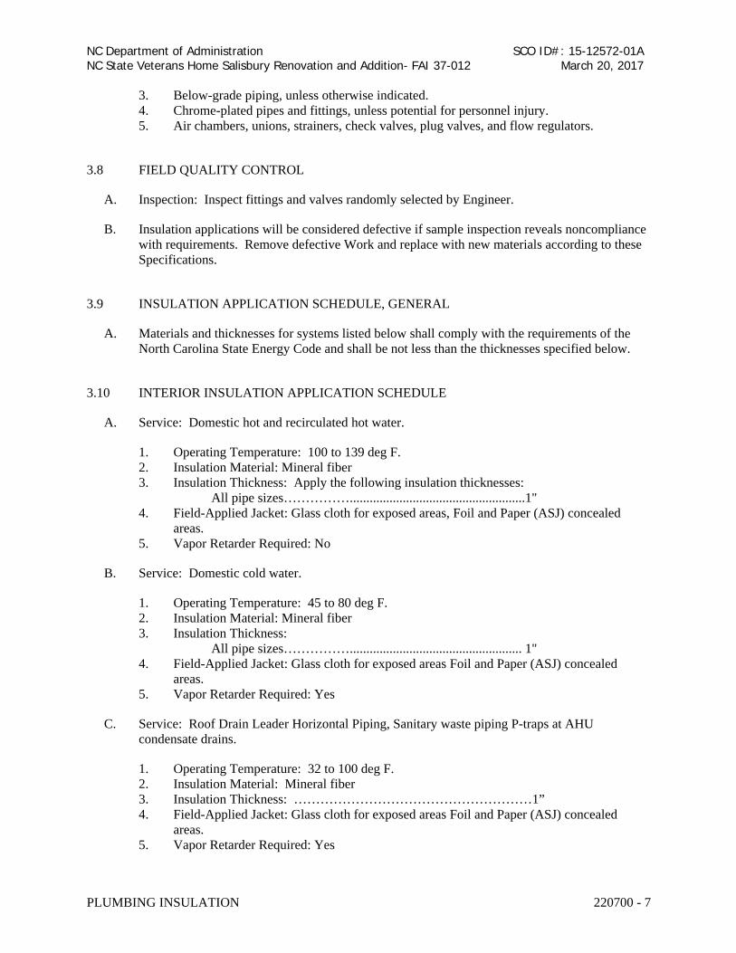
3. Below-grade piping, unless otherwise indicated. 4. Chrome-plated pipes and fittings, unless potential for personnel injury. 5. Air chambers, unions, strainers, check valves, plug valves, and flow regulators.
3.8 FIELD QUALITY CONTROL
A. Inspection: Inspect fittings and valves randomly selected by Engineer.
B. Insulation applications will be considered defective if sample inspection reveals noncompliance with requirements. Remove defective Work and replace with new materials according to these Specifications.
3.9 INSULATION APPLICATION SCHEDULE, GENERAL
A. Materials and thicknesses for systems listed below shall comply with the requirements of the North Carolina State Energy Code and shall be not less than the thicknesses specified below.
3.10 INTERIOR INSULATION APPLICATION SCHEDULE
A. Service: Domestic hot and recirculated hot water.
1. Operating Temperature: 100 to 139 deg F. 2. Insulation Material: Mineral fiber 3. Insulation Thickness: Apply the following insulation thicknesses:
All pipe sizes…………….....................................................1" 4. Field-Applied Jacket: Glass cloth for exposed areas, Foil and Paper (ASJ) concealed
areas. 5. Vapor Retarder Required: No
B. Service: Domestic cold water.
1. Operating Temperature: 45 to 80 deg F. 2. Insulation Material: Mineral fiber 3. Insulation Thickness:
All pipe sizes…………….................................................... 1" 4. Field-Applied Jacket: Glass cloth for exposed areas Foil and Paper (ASJ) concealed
areas. 5. Vapor Retarder Required: Yes
C. Service: Roof Drain Leader Horizontal Piping, Sanitary waste piping P-traps at AHU condensate drains.
1. Operating Temperature: 32 to 100 deg F. 2. Insulation Material: Mineral fiber 3. Insulation Thickness: ………………………………………………1” 4. Field-Applied Jacket: Glass cloth for exposed areas Foil and Paper (ASJ) concealed
areas. 5. Vapor Retarder Required: Yes

NC Department of Administration NC State Veterans Home Salisbury Renovation and Addition- FAI 37-012
SCO ID#: 15-12572-01A March 20, 2017
PLUMBING INSULATION 220700 - 8
D. Service: Exposed sanitary drains and domestic water supplies and stops for fixtures for the disabled.
1. Operating Temperature: 35 to 120 deg F. 2. Insulation Material: Mineral fiber. 3. Insulation Thickness: ……………………………………….…….1” 4. Field-Applied Jacket: PVC P-trap and supply covers. 5. Vapor Retarder Required: Yes
3.11 EXTERIOR INSULATION APPLICATION SCHEDULE
A. This application schedule is for aboveground insulation outside the building.
1. Piping shall be insulated same as interior piping plus with an aluminum weatherproof jacket.
END OF SECTION 220700

NC Department of Administration
NC State Veterans Home Salisbury Emergency Power Upgrade- FAI 37-017
SCO ID#: 15-12572-01B
August 4, 2016
FACILITY WATER DISTRIBUTION PIPING 221113 - 1
SECTION 221113 - FACILITY WATER DISTRIBUTION PIPING
PART 1 - GENERAL
1.01 RELATED DOCUMENTS
A. Drawings and general provisions of the Contract, including General and Supplementary
Conditions and Division 01 Specification Sections, apply to this Section.
1.02 SUMMARY
A. This Section includes water-distribution piping and related components outside the building for
water service and fire-service mains.
B. Utility-furnished products include water meters that will be furnished to the site, ready for
installation.
1.03 DEFINITIONS
A. EPDM: Ethylene propylene diene terpolymer rubber.
B. LLDPE: Linear, low-density polyethylene plastic.
C. PA: Polyamide (nylon) plastic.
D. PE: Polyethylene plastic.
E. PP: Polypropylene plastic.
F. PVC: Polyvinyl chloride plastic.
G. RTRF: Reinforced thermosetting resin (fiberglass) fittings.
H. RTRP: Reinforced thermosetting resin (fiberglass) pipe.
1.04 SUBMITTALS
A. Product Data: For each type of product indicated.
B. Shop Drawings: Detail precast concrete vault assemblies and indicate dimensions, method of
field assembly, and components.
1. Wiring Diagrams: Power, signal, and control wiring for alarms.
NC Department of AdministrationNC State Veterans Home Salisbury Renovation and Addition- FAI 37-012
SCO ID#: 15-12572-01AMarch 20, 2017

NC Department of Administration
NC State Veterans Home Salisbury Emergency Power Upgrade- FAI 37-017
SCO ID#: 15-12572-01B
August 4, 2016
FACILITY WATER DISTRIBUTION PIPING 221113 - 2
C. Coordination Drawings: For piping and specialties including relation to other services in same
area, drawn to scale. Show piping and specialty sizes and valves, meter and specialty locations,
and elevations.
D. Field quality-control test reports.
E. Operation and Maintenance Data: For water valves and specialties to include in emergency,
operation, and maintenance manuals.
1.05 QUALITY ASSURANCE
A. Regulatory Requirements:
1. Comply with standards of authorities having jurisdiction for potable-water-service piping,
including materials, installation, testing, and disinfection.
2. Comply with standards of authorities having jurisdiction for fire-suppression water-
service piping, including materials, hose threads, installation, and testing.
B. Piping materials shall bear label, stamp, or other markings of specified testing agency.
C. Electrical Components, Devices, and Accessories: Listed and labeled as defined in NFPA 70,
Article 100, by a testing agency acceptable to authorities having jurisdiction, and marked for
intended use.
D. Comply with ASTM F 645 for selection, design, and installation of thermoplastic water piping.
E. Comply with FMG's "Approval Guide" or UL's "Fire Protection Equipment Directory" for fire-
service-main products.
F. NFPA Compliance: Comply with NFPA 24 for materials, installations, tests, flushing, and
valve and hydrant supervision for fire-service-main piping for fire suppression.
G. NSF Compliance:
1. Comply with NSF 61 for materials for water-service piping and specialties for domestic
water.
1.06 DELIVERY, STORAGE, AND HANDLING
A. Preparation for Transport: Prepare valves, including fire hydrants, according to the following:
1. Ensure that valves are dry and internally protected against rust and corrosion.
2. Protect valves against damage to threaded ends and flange faces.
3. Set valves in best position for handling. Set valves closed to prevent rattling.
B. During Storage: Use precautions for valves, including fire hydrants, according to the following:
1. Do not remove end protectors unless necessary for inspection; then reinstall for storage.
NC Department of AdministrationNC State Veterans Home Salisbury Renovation and Addition- FAI 37-012
SCO ID#: 15-12572-01AMarch 20, 2017

NC Department of Administration
NC State Veterans Home Salisbury Emergency Power Upgrade- FAI 37-017
SCO ID#: 15-12572-01B
August 4, 2016
FACILITY WATER DISTRIBUTION PIPING 221113 - 3
2. Protect from weather. Store indoors and maintain temperature higher than ambient dew-
point temperature. Support off the ground or pavement in watertight enclosures when
outdoor storage is necessary.
C. Handling: Use sling to handle valves and fire hydrants if size requires handling by crane or lift.
Rig valves to avoid damage to exposed parts. Do not use handwheels or stems as lifting or
rigging points.
D. Deliver piping with factory-applied end caps. Maintain end caps through shipping, storage, and
handling to prevent pipe-end damage and to prevent entrance of dirt, debris, and moisture.
E. Protect stored piping from moisture and dirt. Elevate above grade. Do not exceed structural
capacity of floor when storing inside.
F. Protect flanges, fittings, and specialties from moisture and dirt.
G. Store plastic piping protected from direct sunlight. Support to prevent sagging and bending.
1.07 PROJECT CONDITIONS
A. Interruption of Existing Water-Distribution Service: Do not interrupt service to facilities
occupied by Owner or others unless permitted under the following conditions and then only
after arranging to provide temporary water-distribution service according to requirements
indicated:
1. Notify Construction Manager no fewer than two days in advance of proposed interruption
of service.
2. Do not proceed with interruption of water-distribution service without Town of Cary’s
written permission.
B. Verify existing utility locations. Contact utility-locating service for area where Project is located.
.
C. Verify that water system piping may be installed in compliance with original design and refer-
enced standards.
D. Site Information: Reports on subsurface condition investigations made during the design of the
Project are available for informational purposes only; data in reports are not intended as represen-
tations or warranties of accuracy or continuity of conditions (between soil borings). Owner as-
sumes no responsibility for interpretations or conclusions drawn from this information.
1.08 COORDINATION
A. Coordinate connection to water main with the local regulatory agency.
NC Department of AdministrationNC State Veterans Home Salisbury Renovation and Addition- FAI 37-012
SCO ID#: 15-12572-01AMarch 20, 2017

NC Department of Administration
NC State Veterans Home Salisbury Emergency Power Upgrade- FAI 37-017
SCO ID#: 15-12572-01B
August 4, 2016
FACILITY WATER DISTRIBUTION PIPING 221113 - 4
PART 2 - PRODUCTS
2.01 DUCTILE-IRON PIPE AND FITTINGS
A. Mechanical-Joint, Ductile-Iron Pipe: AWWA C151, with mechanical-joint bell and plain spigot
end unless grooved or flanged ends are indicated.
1. Mechanical-Joint, Ductile-Iron Fittings: AWWA C110, ductile- or gray-iron standard
pattern or AWWA C153, ductile-iron compact pattern.
2. Glands, Gaskets, and Bolts: AWWA C111, ductile- or gray-iron glands, rubber gaskets,
and steel bolts.
B. Push-on-Joint, Ductile-Iron Pipe: AWWA C151, with push-on-joint bell and plain spigot end
unless grooved or flanged ends are indicated.
1. Push-on-Joint, Ductile-Iron Fittings: AWWA C110, ductile- or gray-iron standard
pattern or AWWA C153, ductile-iron compact pattern.
2. Gaskets: AWWA C111, rubber.
C. Flanges: ASME 16.1, Class 125, cast iron.
2.02 PVC PIPE AND FITTINGS
A. PVC, AWWA Pipe: AWWA C900, Class 150, with bell end with gasket, and with spigot end.
1. Comply with UL 1285 for fire-service mains if indicated.
2. PVC Fabricated Fittings: AWWA C900, Class 150, with bell-and-spigot or double-bell
ends. Include elastomeric gasket in each bell.
3. PVC Molded Fittings: AWWA C907, Class 150, with bell-and-spigot or double-bell
ends. Include elastomeric gasket in each bell.
4. Push-on-Joint, Ductile-Iron Fittings: AWWA C110, ductile- or gray-iron standard
pattern or AWWA C153, ductile-iron compact pattern.
a. Gaskets: AWWA C111, rubber.
D. Mechanical-Joint, Ductile-Iron Fittings: AWWA C110, ductile- or gray-iron standard pattern or
AWWA C153, ductile-iron compact pattern.
a. Glands, Gaskets, and Bolts: AWWA C111, ductile- or gray-iron glands, rubber
gaskets, and steel bolts.
2.03 GATE VALVES
A. AWWA, Cast-Iron Gate Valves:
1. Available Manufacturers: Subject to compliance with requirements, manufacturers
offering products that may be incorporated into the Work include, but are not limited to,
the following:
2. Manufacturers: Subject to compliance with requirements, provide products by one of the
following:
NC Department of AdministrationNC State Veterans Home Salisbury Renovation and Addition- FAI 37-012
SCO ID#: 15-12572-01AMarch 20, 2017
NC Department of Administration
NC State Veterans Home Salisbury Emergency Power Upgrade- FAI 37-017
SCO ID#: 15-12572-01B
August 4, 2016
FACILITY WATER DISTRIBUTION PIPING 221113 - 5
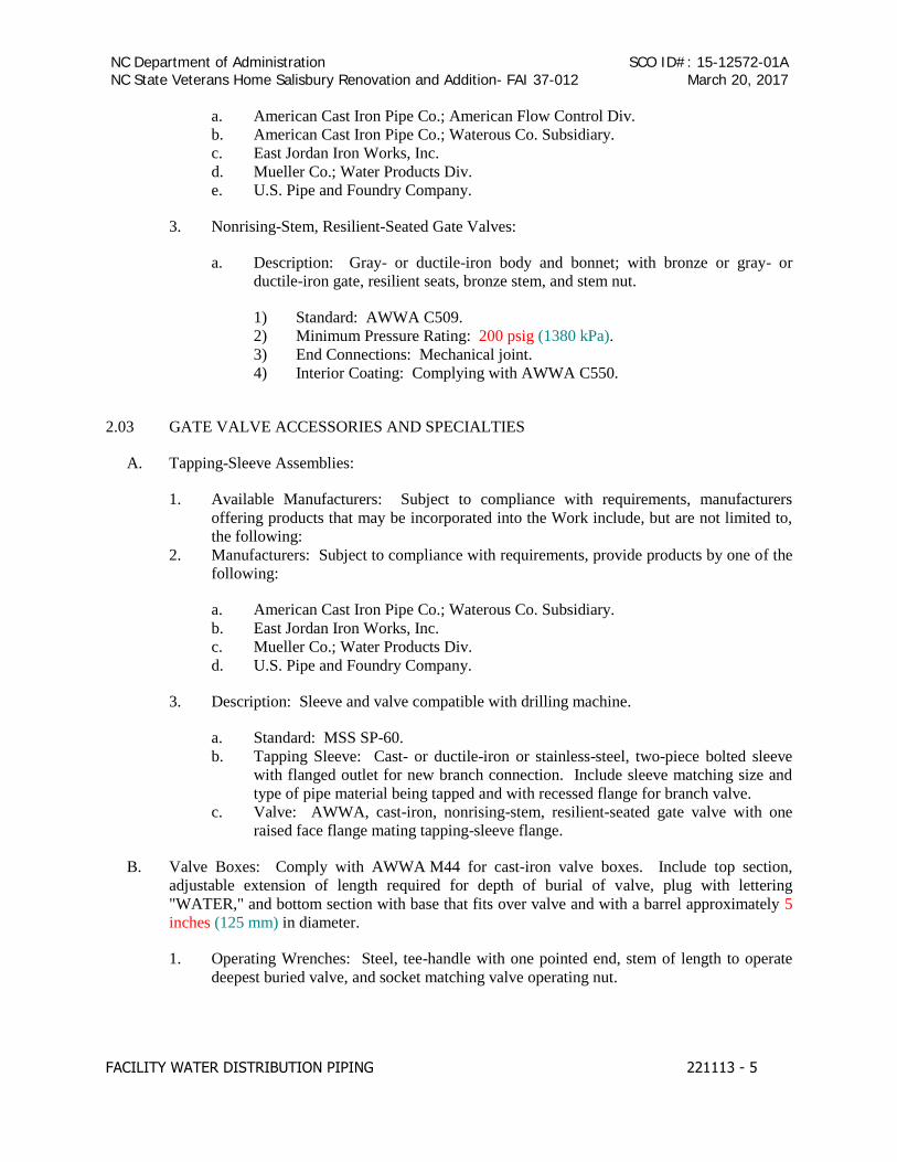
a. American Cast Iron Pipe Co.; American Flow Control Div.
b. American Cast Iron Pipe Co.; Waterous Co. Subsidiary.
c. East Jordan Iron Works, Inc.
d. Mueller Co.; Water Products Div.
e. U.S. Pipe and Foundry Company.
3. Nonrising-Stem, Resilient-Seated Gate Valves:
a. Description: Gray- or ductile-iron body and bonnet; with bronze or gray- or
ductile-iron gate, resilient seats, bronze stem, and stem nut.
1) Standard: AWWA C509.
2) Minimum Pressure Rating: 200 psig (1380 kPa).
3) End Connections: Mechanical joint.
4) Interior Coating: Complying with AWWA C550.
2.03 GATE VALVE ACCESSORIES AND SPECIALTIES
A. Tapping-Sleeve Assemblies:
1. Available Manufacturers: Subject to compliance with requirements, manufacturers
offering products that may be incorporated into the Work include, but are not limited to,
the following:
2. Manufacturers: Subject to compliance with requirements, provide products by one of the
following:
a. American Cast Iron Pipe Co.; Waterous Co. Subsidiary.
b. East Jordan Iron Works, Inc.
c. Mueller Co.; Water Products Div.
d. U.S. Pipe and Foundry Company.
3. Description: Sleeve and valve compatible with drilling machine.
a. Standard: MSS SP-60.
b. Tapping Sleeve: Cast- or ductile-iron or stainless-steel, two-piece bolted sleeve
with flanged outlet for new branch connection. Include sleeve matching size and
type of pipe material being tapped and with recessed flange for branch valve.
c. Valve: AWWA, cast-iron, nonrising-stem, resilient-seated gate valve with one
raised face flange mating tapping-sleeve flange.
B. Valve Boxes: Comply with AWWA M44 for cast-iron valve boxes. Include top section,
adjustable extension of length required for depth of burial of valve, plug with lettering
"WATER," and bottom section with base that fits over valve and with a barrel approximately 5
inches (125 mm) in diameter.
1. Operating Wrenches: Steel, tee-handle with one pointed end, stem of length to operate
deepest buried valve, and socket matching valve operating nut.
NC Department of AdministrationNC State Veterans Home Salisbury Renovation and Addition- FAI 37-012
SCO ID#: 15-12572-01AMarch 20, 2017

NC Department of Administration
NC State Veterans Home Salisbury Emergency Power Upgrade- FAI 37-017
SCO ID#: 15-12572-01B
August 4, 2016
FACILITY WATER DISTRIBUTION PIPING 221113 - 6
C. Indicator Posts: UL 789, FMG-approved, vertical-type, cast-iron body with operating wrench,
extension rod, and adjustable cast-iron barrel of length required for depth of burial of valve.
2.04 FIRE HYDRANTS
A. Dry-Barrel Fire Hydrants:
1. Available Manufacturers: Subject to compliance with requirements, manufacturers
offering products that may be incorporated into the Work include, but are not limited to,
the following:
2. Manufacturers: Subject to compliance with requirements, provide products by one of the
following:
a. American AVK Co.; Valves & Fittings Div.
b. American Cast Iron Pipe Co.; American Flow Control Div.
c. American Cast Iron Pipe Co.; Waterous Co. Subsidiary.
d. American Foundry Group, Inc.
e. East Jordan Iron Works, Inc.
f. McWane, Inc.; Clow Valve Co. Div. (Oskaloosa).
g. McWane, Inc.; Kennedy Valve Div.
h. McWane, Inc.; M & H Valve Company Div.
i. Mueller Co.; Water Products Div.
j. Troy Valve; a division of Penn-Troy Manufacturing, Inc.
k. U.S. Pipe and Foundry Company.
3. Description: Freestanding, with one NPS 4-1/2 (DN 115) and two NPS 2-1/2 (DN 65)
outlets, 5-1/4-inch (133-mm) main valve, drain valve, and NPS 6 (DN 150) mechanical-
joint inlet. Include interior coating according to AWWA C550. Hydrant shall have cast-
iron body, compression-type valve opening against pressure and closing with pressure.
a. Standard: AWWA C502.
b. Pressure Rating: 150 psig (1035 kPa) minimum.
c. Outlet Threads: NFPA 1963, with external hose thread used by the Town of Siler
City. Include cast-iron caps with steel chains.
d. Operating and Cap Nuts: Pentagon, 1-1/2 inches (38 mm) point to flat.
e. Direction of Opening: Open hydrant valve by turning operating nut to left or
counterclockwise.
f. Exterior Finish: Exterior alkyd-gloss enamel paint per Siler Citys requirements.
2.05 FIRE DEPARTMENT CONNECTIONS
A. Fire Department Connections:
1. Manufacturers: Subject to compliance with requirements, provide products by one of the
following:
a. Elkhart Brass Mfg. Co., Inc.
b. Fire End & Croker Corporation.
c. Guardian Fire Equipment, Inc.
NC Department of AdministrationNC State Veterans Home Salisbury Renovation and Addition- FAI 37-012
SCO ID#: 15-12572-01AMarch 20, 2017

NC Department of Administration
NC State Veterans Home Salisbury Emergency Power Upgrade- FAI 37-017
SCO ID#: 15-12572-01B
August 4, 2016
FACILITY WATER DISTRIBUTION PIPING 221113 - 7
d. Kidde Fire Fighting.
e. Potter Roemer.
f. Reliable Automatic Sprinkler Co., Inc.
2. Description: Freestanding, with cast-bronze body, thread inlets according to NFPA 1963
and matching local fire department hose threads, and threaded bottom outlet. Include
lugged caps, gaskets, and chains; lugged swivel connection and drop clapper for each
hose-connection inlet; 18-inch- (460-mm-) high brass sleeve; and round escutcheon plate.
a. Standard: UL 405.
b. Connections: Two NPS 2-1/2 (DN 65) inlets and one [NPS 4 (DN 100)] [NPS 6
(DN 150)] outlet.
c. Connections: Three NPS 2-1/2 (DN 65) inlets and one NPS 6 (DN 150) outlet.
d. Inlet Alignment: horizontal.
e. Finish Including Sleeve: Polished chrome-plated.
f. Escutcheon Plate Marking: "STANDPIPE."
2.06 ALARM DEVICES
A. Alarm Devices, General: UL 753 and FMG approved, of types and sizes to mate and match
piping and equipment.
B. Water-Flow Indicators: Vane-type water-flow detector, rated for 250-psig (1725-kPa) working
pressure; designed for horizontal or vertical installation; with 2 single-pole, double-throw circuit
switches to provide isolated alarm and auxiliary contacts, 7 A, 125-V ac and 0.25 A, 24-V dc;
complete with factory-set, field-adjustable retard element to prevent false signals and
tamperproof cover that sends signal when cover is removed.
C. Supervisory Switches: Single pole, double throw; designed to signal valve in other than fully
open position.
D. Pressure Switches: Single pole, double throw; designed to signal increase in pressure.
PART 3 - EXECUTION
3.01 EARTHWORK
A. Refer to Division 31 Section “Earth Moving” for excavating, trenching, and backfilling.
3.02 PIPING APPLICATIONS
A. General: Use pipe, fittings, and joining methods for piping systems according to the following
applications.
B. Transition couplings and special fittings with pressure ratings at least equal to piping pressure
rating may be used, unless otherwise indicated.
NC Department of AdministrationNC State Veterans Home Salisbury Renovation and Addition- FAI 37-012
SCO ID#: 15-12572-01AMarch 20, 2017
NC Department of Administration
NC State Veterans Home Salisbury Emergency Power Upgrade- FAI 37-017
SCO ID#: 15-12572-01B
August 4, 2016
FACILITY WATER DISTRIBUTION PIPING 221113 - 8
C. Do not use flanges or unions for underground piping.
D. Flanges, unions, grooved-end-pipe couplings, and special fittings may be used, instead of joints
indicated, on aboveground piping and piping in vaults.
E. Underground water-service piping NPS 4 to NPS 8 (DN 100 to DN 200) shall be the following:
1. NPS 8 (DN 200): PVC, AWWA Class 200 pipe; restrained joint fittings; and gasketed
joints.
F. Underground Fire-Service-Main Piping NPS 4 to NPS 12 (DN 100 to DN 300) shall be the
following:
1. Ductile-iron, mechanical-joint pipe joints.
2. PE, Class 150, fire-service pipe; molded PE fittings; and heat-fusion joints.
3. PVC, AWWA Class 150 pipe listed for fire-protection service; PVC Class 150 fabricated
or molded fittings; and gasketed joints.
4. PVC, AWWA Class 200 pipe listed for fire-protection service; PVC Class 200 fabricated
fittings; and gasketed joints.
5. Fiberglass, AWWA, FMG-approved RTRP, Class 150; RTRF; and gasketed joints.
6. Fiberglass, UL RTRP, Class 150; RTRF; and gasketed joints.
3.03 VALVE APPLICATIONS
A. General Application: Use mechanical-joint-end valves for NPS 3 (DN 80) and larger
underground installation. Use threaded- or flanged-end valves for installation in vaults. Use
UL/FMG, nonrising-stem gate valves for installation with indicator posts. Use corporation
valves and curb valves with ends compatible with piping, for NPS 2 (DN 50) and smaller
installation.
B. Drawings indicate valve types to be used. Where specific valve types are not indicated, the
following requirements apply:
1. Underground Valves, NPS 3 (DN 80) and Larger: AWWA, cast-iron, nonrising-stem, ,
resilient-seated gate valves with valve box.
2. Underground Valves, NPS 4 (DN 100) and Larger, for Indicator Posts: UL/FMG, cast-
iron, nonrising-stem gate valves with indicator post.
3. Use the following for valves in vaults and aboveground:
a. Gate Valves, NPS 2 (DN 50) and Smaller: Bronze, nonrising stem.
b. Gate Valves, NPS 3 (DN 80) and Larger: AWWA, cast iron .
3.04 PIPING SYSTEMS - COMMON REQUIREMENTS
A. See Division 22 Section "Common Work Results for Plumbing" for piping-system common
requirements.
NC Department of AdministrationNC State Veterans Home Salisbury Renovation and Addition- FAI 37-012
SCO ID#: 15-12572-01AMarch 20, 2017

NC Department of Administration
NC State Veterans Home Salisbury Emergency Power Upgrade- FAI 37-017
SCO ID#: 15-12572-01B
August 4, 2016
FACILITY WATER DISTRIBUTION PIPING 221113 - 9
3.05 PIPING INSTALLATION
A. Water-Main Connection: Arrange with utility company for tap of size and in location indicated
in water main.
B. Make connections larger than NPS 2 (DN 50) with tapping machine according to the following:
1. Install tapping sleeve and tapping valve according to MSS SP-60.
2. Install tapping sleeve on pipe to be tapped. Position flanged outlet for gate valve.
3. Use tapping machine compatible with valve and tapping sleeve; cut hole in main.
Remove tapping machine and connect water-service piping.
4. Install gate valve onto tapping sleeve. Comply with MSS SP-60. Install valve with stem
pointing up and with valve box.
C. Make connections NPS 2 (DN 50) and smaller with drilling machine according to the following:
1. Install service-saddle assemblies and corporation valves in size, quantity, and
arrangement required by utility company standards.
2. Install service-saddle assemblies on water-service pipe to be tapped. Position outlets for
corporation valves.
3. Use drilling machine compatible with service-saddle assemblies and corporation valves.
Drill hole in main. Remove drilling machine and connect water-service piping.
4. Install corporation valves into service-saddle assemblies.
5. Install manifold for multiple taps in water main.
6. Install curb valve in water-service piping with head pointing up and with service box.
D. Bury piping with depth of cover over top at least 42 inches below the proposed grade.
E. Extend water-service piping and connect to water-supply source and building-water-piping
systems at outside face of building wall in locations and pipe sizes indicated.
1. Terminate water-service piping at building wall until building-water-piping systems are
installed. Terminate piping with caps, plugs, or flanges as required for piping material.
Make connections to building-water-piping systems when those systems are installed.
F. Sleeves are specified in Division 22 Section "Common Work Results for Plumbing."
G. Mechanical sleeve seals are specified in Division 22 Section "Common Work Results for
Plumbing."
H. Install underground piping with restrained joints at horizontal and vertical changes in direction.
Use restrained-joint piping, thrust blocks, anchors, tie-rods and clamps, and other supports.
I. See Division 21 Section "Water-Based Fire-Suppression Systems" for fire-suppression-water
piping inside the building.
J. See Division 22 Section "Domestic Water Piping" for potable-water piping inside the building.
NC Department of AdministrationNC State Veterans Home Salisbury Renovation and Addition- FAI 37-012
SCO ID#: 15-12572-01AMarch 20, 2017

NC Department of Administration
NC State Veterans Home Salisbury Emergency Power Upgrade- FAI 37-017
SCO ID#: 15-12572-01B
August 4, 2016
FACILITY WATER DISTRIBUTION PIPING 221113 - 10
3.06 JOINT CONSTRUCTION
A. See Division 22 Section “Common Work Results for Plumbing” for basic piping joint
construction.
B. Acceptable types of fittings are the following:
1. Full Body Mechanical Joint Fittings: Full body ductile iron mechanical joint fittings
shall be class 250 minimum and shall conform to AWWA C110/ANSI A21.10. Glands,
Gaskets and Bolts shall conform to AWWA C111/ANSI A21.11.
2. Mechanical Joint Fittings-Compact: Compact fittings shall be minimum class 350 and
shall compley with AWWA C 153/ANSI A21.53, pipe sizes 4 inches through 48 inches.
Glands, Gaskets and Bolts shall conform to AWWA C111/ANSI A21.11.
3. Mechanical Joint Restraints: Joint restraints shall consist of the use of a Megalug joint
restraint system using Megalug series 1100 mechanical joint restraint by EBAA Iron
Sales, Inc., Ford wedge action restrainer gland UFR Series 1400, or approved equal. Bolt
heads are to be “auto-torque” twist off.
3.07 ANCHORAGE INSTALLATION
A. Anchorage, General: Install water-distribution piping with restrained joints. Anchorages and
restrained-joint types that may be used include the following:
1. Concrete thrust blocks.
2. Locking mechanical joints.
3. Set-screw mechanical retainer glands.
4. Bolted flanged joints.
5. Heat-fused joints.
6. Pipe clamps and tie rods.
B. Install anchorages for tees, plugs and caps, bends, crosses, valves, and hydrant branches.
Include anchorages for the following piping systems:
1. Gasketed-Joint, Ductile-Iron, Water-Service Piping: According to AWWA C600.
2. Bonded-Joint Fiberglass, Water-Service Piping: According to AWWA M45.
3. Fire-Service-Main Piping: According to NFPA 24.
C. Apply full coat of asphalt or other acceptable corrosion-resistant material to surfaces of installed
ferrous anchorage devices.
3.08 VALVE INSTALLATION
A. AWWA Gate Valves: Comply with AWWA C600 and AWWA M44. Install each
underground valve with stem pointing up and with valve box.
B. AWWA Valves Other Than Gate Valves: Comply with AWWA C600 and AWWA M44.
C. UL/FMG, Gate Valves: Comply with NFPA 24. Install each underground valve and valves in
vaults with stem pointing up and with vertical cast-iron indicator post.
NC Department of AdministrationNC State Veterans Home Salisbury Renovation and Addition- FAI 37-012
SCO ID#: 15-12572-01AMarch 20, 2017
NC Department of Administration
NC State Veterans Home Salisbury Emergency Power Upgrade- FAI 37-017
SCO ID#: 15-12572-01B
August 4, 2016
FACILITY WATER DISTRIBUTION PIPING 221113 - 11
D. UL/FMG, Valves Other Than Gate Valves: Comply with NFPA 24.
E. MSS Valves: Install as component of connected piping system.
F. Corporation Valves and Curb Valves: Install each underground curb valve with head pointed
up and with service box
3.09 FIRE HYDRANT INSTALLATION
A. General: Install each fire hydrant with separate gate valve in supply pipe, anchor with
restrained joints or thrust blocks, and support in upright position.
B. Wet-Barrel Fire Hydrants: Install with valve below frost line. Provide for drainage.
C. AWWA Fire Hydrants: Comply with AWWA M17.
D. UL/FMG Fire Hydrants: Comply with NFPA 24.
3.10 FIRE DEPARTMENT CONNECTION INSTALLATION
A. Install ball drip valves at each check valve for fire department connection to mains.
3.11 ALARM DEVICE INSTALLATION
A. General: Comply with NFPA 24 for devices and methods of valve supervision. Underground
valves with valve box do not require supervision.
B. Supervisory Switches: Supervise valves in open position.
1. Valves: Grind away portion of exposed valve stem. Bolt switch, with plunger in stem
depression, to OS&Y gate-valve yoke.
2. Indicator Posts: Drill and thread hole in upper-barrel section at target plate. Install
switch, with toggle against target plate, on barrel of indicator post.
C. Locking and Sealing: Secure unsupervised valves as follows:
1. Valves: Install chain and padlock on open OS&Y gate valve.
2. Post Indicators: Install padlock on wrench on indicator post.
D. Pressure Switches: Drill and thread hole in exposed barrel of fire hydrant. Install switch.
E. Water-Flow Indicators: Install in water-service piping in vault. Select indicator with saddle
and vane matching pipe size. Drill hole in pipe, insert vane, and bolt saddle to pipe.
F. Connect alarm devices to building fire alarm system. Wiring and fire-alarm devices are
specified in Division 28 Section "Fire Detection and Alarm."
NC Department of AdministrationNC State Veterans Home Salisbury Renovation and Addition- FAI 37-012
SCO ID#: 15-12572-01AMarch 20, 2017

NC Department of Administration
NC State Veterans Home Salisbury Emergency Power Upgrade- FAI 37-017
SCO ID#: 15-12572-01B
August 4, 2016
FACILITY WATER DISTRIBUTION PIPING 221113 - 12
3.12 CONNECTIONS
A. Piping installation requirements are specified in other Division 22 Sections. Drawings indicate
general arrangement of piping, fittings, and specialties.
B. See Division 22 Section "Common Work Results for Plumbing" for piping connections to
valves and equipment.
C. Connect water-distribution piping to utility water main. Connect water-distribution piping to
interior domestic water and fire-suppression piping.
D. Connect waste piping from concrete vault drains to storm-drainage system. See Division 33
Section "Storm Utility Drainage Piping" for connection to storm-sewer piping.
E. Ground equipment according to Division 26 Section "Grounding and Bonding for Electrical
Systems."
F. Connect wiring according to Division 26 Section "Low-Voltage Electrical Power Conductors
and Cables."
3.13 IDENTIFICATION
A. Install continuous underground detectable warning tape during backfilling of trench for
underground water-distribution piping. Locate below finished grade, directly over piping.
Underground warning tapes are specified in Division 31 Section "Earth Moving."
B. Permanently attach equipment nameplate or marker indicating plastic water-service piping, on
main electrical meter panel. See Division 22 Section "Common Work Results for Plumbing"
for identifying devices.
3.14 FIELD QUALITY CONTROL
A. Piping Tests: Conduct piping tests before joints are covered and after concrete thrust blocks
have hardened sufficiently. Fill pipeline 24 hours before testing and apply test pressure to
stabilize system. Use only potable water. Contractor to coordinate with Designer and the Utility
Owner’s Inspector for witnessing of all test and flush procedures
B. Hydrostatic Tests: Test at not less than one-and-one-half times working pressure for two hours.
1. Increase pressure in 50-psig increments and inspect each joint between increments. Hold
at test pressure for 1 hour; decrease to 0 psig. Slowly increase again to test pressure and
hold for 1 more hour. Maximum allowable leakage is 2 quarts per hour per 100 joints.
Remake leaking joints with new materials and repeat test until leakage is within above
limits. The amount of allowable leakage specified can be increased by 1 fluid ounce per
inch valve diameter per hr. for each metal seated valve isolating the test section. If dry
barrel hydrants are tested with the main valve open so the hydrant are under pressure, an
additional 5 ounces per minute leakage is permitted for each hydrant. Prepare reports of
testing activities.
NC Department of AdministrationNC State Veterans Home Salisbury Renovation and Addition- FAI 37-012
SCO ID#: 15-12572-01AMarch 20, 2017
NC Department of Administration
NC State Veterans Home Salisbury Emergency Power Upgrade- FAI 37-017
SCO ID#: 15-12572-01B
August 4, 2016
FACILITY WATER DISTRIBUTION PIPING 221113 - 13
2. Conduct all hydrostatic tests in accordance with article 312.5 of the North Carolina
Plumbing Code and NFPA-24.
C. Flushing: Flow the required flow rate until water is clear as indicated by no collection of
foreign material in burlap bags at outlets such as hydrants and blow-offs. Flush at flows not
less than 390 gpm for 4-inch, 880 gpm for 6-inch, 1,560 gpm for 8-inch, 2,440 gpm for 10-
inch, 3,520 gpm for 12-inch pipe. When supply cannot produce stipulated flow rates, obtain
maximum available.
3.15 CLEANING
A. Clean and disinfect water distribution piping as follows:
1. Purge new water distribution piping systems and parts of existing systems that have been al-
tered, extended, or repaired prior to use.
2. Use purging and disinfecting procedure prescribed by authority having jurisdiction or, if meth-
od is not prescribed by that authority, use procedure described in AWWA C651 or as described
below:
a. Comply with NFPA 24 for flushing of piping. Flush piping system with clean, potable wa-
ter until dirty water does not appear at points of outlet.
b. Fill system or part of system with water/chlorine solution containing at least 50 parts per
million of chlorine. Isolate (valve off) system or part thereof and allow to stand for 24
hours.
c. Drain system or part of system of previous solution and refill with water/chlorine solution
containing at least 200 parts per million of chlorine; isolate and allow to stand for 3 hours.
d. Following allowed standing time, flush system with clean, potable water until chlorine does
not remain in water coming from system.
e. Submit water samples in sterile bottles to authority having jurisdiction. Repeat procedure if
biological examination made by authority shows evidence of contamination.
B. Prepare reports for purging and disinfecting activities.
END OF SECTION 221113
NC Department of AdministrationNC State Veterans Home Salisbury Renovation and Addition- FAI 37-012
SCO ID#: 15-12572-01AMarch 20, 2017

THIS PAGE INTENTIONALLY LEFT BLANK

NC Department of Administration NC State Veterans Home Salisbury Renovation and Addition- FAI 37-012
SCO ID#: 15-12572-01A March 20, 2017
DOMESTIC WATER PIPING 221116 - 1
SECTION 221116 - DOMESTIC WATER PIPING
PART 1 - GENERAL
1.1 RELATED DOCUMENTS
A. Drawings and general provisions of the Contract, including General and Supplementary Conditions and Division 1 Specification Sections, apply to this Section.
1.2 SUMMARY
A. This Section includes domestic water piping from locations indicated to fixtures and equipment inside the building.
B. Related Sections include the following:
1. Division 22 Section "Meters and Gages" for thermometers, pressure gages, and fittings. 2. Division 22 Section "Plumbing Specialties" for water distribution piping specialties.
1.3 SUBMITTALS
A. Product Data: For pipe, tube, fittings, and couplings.
1.4 QUALITY ASSURANCE
A. Piping materials shall bear label, stamp, or other markings of specified testing agency.
B. Comply with NSF 61, "Drinking Water System Components-Health Effects; Sections 1 through 9," for potable domestic water piping and components.
PART 2 - PRODUCTS
2.1 PIPING MATERIALS
A. Refer to Part 3 "Piping Applications" Article for applications of pipe, tube, fitting, and joining materials.
B. Transition Couplings for Aboveground Pressure Piping: Coupling or other manufactured fitting the same size as, with pressure rating at least equal to and ends compatible with, piping to be joined.
2.2 COPPER TUBING

NC Department of Administration NC State Veterans Home Salisbury Renovation and Addition- FAI 37-012
SCO ID#: 15-12572-01A March 20, 2017
DOMESTIC WATER PIPING 221116 - 2
A. Soft Copper Tube: ASTM B 88, Types K and L, water tube, annealed temper.
1. Copper Pressure Fittings: ASME B16.22, wrought-copper, solder-joint fittings. 2. Bronze Flanges: ASME B16.24, Class 150, with solder-joint end. Furnish Class 300
flanges if required to match piping. 3. Copper Unions: MSS SP-123, cast-copper-alloy, hexagonal-stock body, with ball-and-
socket, metal-to-metal seating surfaces and solder-joint or threaded ends.
B. Hard Copper Tube: ASTM B 88, Types L, water tube, drawn temper.
1. Copper Pressure Fittings: ASME B16.22, wrought- copper, solder-joint fittings. 2. Bronze Flanges: ASME B16.24, Class 150, with solder-joint end. Furnish Class 300
flanges if required to match piping. 3. Copper Unions: MSS SP-123, cast-copper-alloy, hexagonal-stock body, with ball-and-
socket, metal-to-metal seating surfaces and solder-joint or threaded ends.
2.3 DIELECTRIC FITTINGS
A. General Requirements: Assembly of copper alloy and ferrous materials or ferrous material body with separating nonconductive insulating material suitable for system fluid, pressure, and temperature.
B. Dielectric Unions:
1. Description:
a. Pressure Rating: 150 psig at 180 deg F. b. End Connections: Solder-joint copper alloy and threaded ferrous.
C. Dielectric Flanges:
1. Description:
a. Factory-fabricated, bolted, companion-flange assembly. b. Pressure Rating: 175 psig minimum. c. End Connections: Solder-joint copper alloy and threaded ferrous; threaded solder-
joint copper alloy and threaded ferrous.
2.4 ESCUTCHEONS
A. General: Manufactured ceiling, floor, and wall escutcheons and floor plates.
B. One Piece, Cast Brass: Polished, chrome-plated finish with setscrews.
C. One Piece, Deep Pattern: Deep-drawn, box-shaped brass with chrome-plated finish.

NC Department of Administration NC State Veterans Home Salisbury Renovation and Addition- FAI 37-012
SCO ID#: 15-12572-01A March 20, 2017
DOMESTIC WATER PIPING 221116 - 3
2.5 SLEEVES
A. Cast-Iron Wall Pipes: Fabricated of cast iron, and equivalent to ductile-iron pressure pipe, with plain ends and integral waterstop unless otherwise indicated.
B. Galvanized-Steel-Pipe Sleeves: ASTM A 53/A 53M, Type E, Grade B, Schedule 40, zinc-coated, with plain ends.
C. Stack Sleeve Fittings: Manufactured, cast-iron sleeve with integral clamping flange. Include clamping ring and bolts and nuts for membrane flashing.
2.6 SLEEVE SEALS
A. Description: Modular sealing element unit, designed for field assembly, used to fill annular space between pipe and sleeve.
1. Sealing Elements: EPDM-rubber interlocking links shaped to fit surface of pipe. Include type and number required for pipe material and size of pipe.
2. Pressure Plates: Stainless steel. 3. Connecting Bolts and Nuts: Stainless steel of length required to secure pressure plates to
sealing elements.
PART 3 - EXECUTION
3.1 EARTHWORK
A. Comply with requirements in Division 31 Section "Earth Moving" for excavating, trenching, and backfilling.
3.2 PIPING INSTALLATION
A. Drawing plans, schematics, and diagrams indicate general location and arrangement of domestic water piping. Indicated locations and arrangements are used to size pipe and calculate friction loss, expansion, and other design considerations. Install piping as indicated unless deviations to layout are approved on Coordination Drawings.
B. Install copper tubing under building slab according to CDA's "Copper Tube Handbook."
C. Install domestic water piping level and plumb.
D. Install piping concealed from view and protected from physical contact by building occupants unless otherwise indicated and except in equipment rooms and service areas.
E. Install piping indicated to be exposed and piping in equipment rooms and service areas at right angles or parallel to building walls. Diagonal runs are prohibited unless specifically indicated otherwise.

NC Department of Administration NC State Veterans Home Salisbury Renovation and Addition- FAI 37-012
SCO ID#: 15-12572-01A March 20, 2017
DOMESTIC WATER PIPING 221116 - 4
F. Install piping above accessible ceilings to allow sufficient space for ceiling panel removal, and coordinate with other services occupying that space.
G. Install piping adjacent to equipment and specialties to allow service and maintenance.
H. Install piping to permit valve servicing.
I. Install piping free of sags and bends.
J. Install fittings for changes in direction and branch connections.
K. Install unions in copper tubing at final connection to each piece of equipment, machine, and specialty.
3.3 PIPING APPLICATIONS
A. Transition and special fittings with pressure ratings at least equal to piping rating may be used in applications below, unless otherwise indicated.
B. Aboveground Domestic Water Piping: Use the following piping materials for each size range:
1. NPS 4” and Smaller: Hard copper tube, Type L; copper pressure fittings and joints.
3.4 JOINT CONSTRUCTION
A. Brazed Joints: Join copper tube and fittings according to CDA's "Copper Tube Handbook," "Brazed Joints" Chapter.
B. Soldered Joints: Use ASTM B 813, water-flushable, lead-free flux; ASTM B 32, lead-free-alloy solder; and ASTM B 828 procedure, unless otherwise indicated solder shall be 95-5 for pipe sizes 1 ¼” and smaller. Pipe larger than 1 ½”: shall be brazed.
C. Dissimilar-Material Piping Joints: Make joints using adapters compatible with materials of both piping systems.
3.5 HANGER AND SUPPORT INSTALLATION
A. Refer to Division 22 Section "Hangers and Supports" for pipe hanger and support devices. Install the following:
1. Vertical Piping: MSS Type 8 or Type 42, clamps. 2. Individual, Straight, Horizontal Piping Runs: According to the following:
a. 100 Feet and Less: MSS Type 1, adjustable, steel clevis hangers. b. Longer Than 100 Feet: MSS Type 43, adjustable roller hangers.
3. Multiple, Straight, Horizontal Piping Runs 100 Feet or Longer: MSS Type 44, pipe rolls. Support pipe rolls on trapeze.
4. Base of Vertical Piping: MSS Type 52, spring hangers.
NC Department of Administration NC State Veterans Home Salisbury Renovation and Addition- FAI 37-012
SCO ID#: 15-12572-01A March 20, 2017
DOMESTIC WATER PIPING 221116 - 5
B. Install supports according to Division 22 Section "Hangers and Supports."
C. Support vertical piping and tubing at base and at each floor.
D. Rod diameter may be reduced 1 size for double-rod hangers, to a minimum of 3/8 inch.
E. Install hangers for copper tubing with the following maximum horizontal spacing and minimum rod diameters:
1. NPS 3/4 and Smaller: 60 inches with 3/8-inch rod. 2. NPS 1 and NPS 1-1/4: 72 inches with 3/8-inch rod. 3. NPS 1-1/2 and NPS 2: 96 inches with 3/8-inch rod. 4. NPS 2-1/2: 108 inches with 1/2-inch rod. 5. NPS 3 to NPS 5: 10 feet with 1/2-inch rod. 6. NPS 6: 10 feet with 5/8-inch rod.
F. Install supports for vertical copper tubing every 10 feet.
G. Support piping and tubing not listed above according to MSS SP-69 and manufacturer's written instructions.
3.6 VALVE INSTALLATION
A. General-Duty Valves: Comply with requirements in Division 22 Section "General-Duty Valves for Plumbing Piping" for valve installations.
B. Install shutoff valve close to water main on each branch and riser serving plumbing fixtures or equipment, on each water supply to equipment, and on each water supply to plumbing fixtures that do not have supply stops. Use ball or gate valves for piping NPS 2 and smaller. Use butterfly or gate valves for piping NPS 2-1/2 and larger.
C. Install drain valves for equipment at base of each water riser, at low points in horizontal piping, and where required to drain water piping. Drain valves are specified in Division 22 Section "Domestic Water Piping Specialties."
1. Hose-End Drain Valves: At low points in water mains, risers, and branches. 2. Stop-and-Waste Drain Valves: Instead of hose-end drain valves where indicated.
D. Install calibrated balancing valves in each hot-water circulation return branch and discharge side of each pump and circulator. Set calibrated balancing valves partly open to restrict but not stop flows.
3.7 TRANSITION FITTING INSTALLATION
A. Install transition couplings at joints of dissimilar piping.
3.8 DIELECTRIC FITTING INSTALLATION
A. Install dielectric fittings in piping at connections of dissimilar metal piping and tubing.

NC Department of Administration NC State Veterans Home Salisbury Renovation and Addition- FAI 37-012
SCO ID#: 15-12572-01A March 20, 2017
DOMESTIC WATER PIPING 221116 - 6
3.9 ESCUTCHEON INSTALLATION
A. Install escutcheons for exposed pipe penetrations of walls, ceilings, and floors.
3.10 SLEEVE INSTALLATION
A. General Requirements: Install sleeves for pipes and tubes passing through penetrations in floors, partitions, roofs, and walls.
B. Install sleeves in new partitions, slabs, and walls as they are built.
C. For interior wall penetrations, seal annular space between sleeve and pipe or pipe insulation using joint sealants appropriate for size, depth, and location of joint. For exterior wall penetrations above grade, seal annular space between sleeve and pipe using joint sealants appropriate for size, depth, and location of joint. Comply with requirements in Division 07 Section "Joint Sealants" for joint sealants.
D. For exterior wall penetrations below grade, seal annular space between sleeve and pipe using sleeve seals specified in this Section.
E. Seal space outside of sleeves in concrete slabs and walls with grout.
F. Install sleeves that are large enough to provide 1/4-inch annular clear space between sleeve and pipe or pipe insulation unless otherwise indicated.
G. Install sleeve materials according to the following applications:
1. Sleeves for Piping Passing through Concrete Floor Slabs: Steel pipe. 2. Sleeves for Piping Passing through Concrete Floor Slabs of Mechanical Equipment Areas
or Other Wet Areas: Steel pipe.
a. Extend sleeves 2 inches above finished floor level. b. For pipes penetrating floors with membrane waterproofing, extend cast-iron sleeve
fittings below floor slab as required to secure clamping ring if ring is specified. Secure flashing between clamping flanges. Install section of cast-iron soil pipe to extend sleeve to 2 inches above finished floor level.
3. Sleeves for Piping Passing through Gypsum-Board Partitions:
a. Steel pipe sleeves for pipes smaller than NPS 6. b. Galvanized-steel sheet sleeves for pipes NPS 6 and larger. c. Exception: Sleeves are not required for water supply tubes and waste pipes for
individual plumbing fixtures if escutcheons will cover openings.
4. Sleeves for Piping Passing through Concrete Roof Slabs: Steel pipe. 5. Sleeves for Piping Passing through Exterior Concrete Walls:
a. Steel pipe sleeves for pipes smaller than NPS 6. b. Cast-iron wall pipe sleeves for pipes NPS 6 and larger.
NC Department of Administration NC State Veterans Home Salisbury Renovation and Addition- FAI 37-012
SCO ID#: 15-12572-01A March 20, 2017
DOMESTIC WATER PIPING 221116 - 7
c. Install sleeves that are large enough to provide 1-inch annular clear space between sleeve and pipe or pipe insulation when sleeve seals are used.
H. Fire-Barrier Penetrations: Maintain indicated fire rating of walls, partitions, ceilings, and floors at pipe penetrations. Seal pipe penetrations with firestop materials.
3.11 SLEEVE SEAL INSTALLATION
A. Install sleeve seals in sleeves in exterior concrete walls at water-service piping entries into building.
B. Select type and number of sealing elements required for pipe material and size. Position pipe in center of sleeve. Assemble sleeve seal components and install in annular space between pipe and sleeve. Tighten bolts against pressure plates that cause sealing elements to expand and make watertight seal.
3.12 IDENTIFICATION
A. Identify system components. Comply with requirements in Division 22 Section "Identification for Plumbing Piping and Equipment" for identification materials and installation.
3.13 FIELD QUALITY CONTROL
A. Perform tests and inspections.
B. Piping Tests:
1. Fill domestic water piping. Check components to determine that they are not air bound and that piping is full of water.
2. Test for leaks and defects in new piping and parts of existing piping that have been altered, extended, or repaired.
3. Cap and subject piping to static water pressure of 50 psig (125 psig minimum) above operating pressure, without exceeding pressure rating of piping system materials. Isolate test source and allow to stand for four hours. Leaks and loss in test pressure constitute defects that must be repaired.
3.14 CLEANING
A. Clean and disinfect potable domestic water piping as follows:
1. Purge new piping and parts of existing piping that have been altered, extended, or repaired before using.
2. Use purging and disinfecting procedures prescribed by authorities having jurisdiction; if methods are not prescribed, use procedures described in either AWWA C651 or AWWA C652 or follow procedures described below:
a. Flush piping system with clean, potable water until dirty water does not appear at outlets.

NC Department of Administration NC State Veterans Home Salisbury Renovation and Addition- FAI 37-012
SCO ID#: 15-12572-01A March 20, 2017
DOMESTIC WATER PIPING 221116 - 8
b. Fill and isolate system according to either of the following:
1) Fill system or part thereof with water/chlorine solution with at least 50 ppm of chlorine. Isolate with valves and allow to stand for 24 hours.
2) Fill system or part thereof with water/chlorine solution with at least 200 ppm of chlorine. Isolate and allow to stand for three hours.
c. Flush system with clean, potable water until no chlorine is in water coming from system after the standing time.
d. Submit water samples in sterile bottles to authorities having jurisdiction. Repeat procedures if biological examination shows contamination.
B. Prepare and submit reports of purging and disinfecting activities.
C. Clean interior of domestic water piping system. Remove dirt and debris as work progresses.
END OF SECTION 221116

NC Department of Administration NC State Veterans Home Salisbury Renovation and Addition- FAI 37-012
SCO ID#: 15-12572-01A March 20, 2017
DOMESTIC WATER PIPING SPECIALTIES 221119 - 1
SECTION 221119 - DOMESTIC WATER PIPING SPECIALTIES
PART 1 - GENERAL
1.1 SUMMARY
A. This Section includes the following domestic water piping specialties:
1. Vacuum breakers. 2. Backflow preventers. 3. Water pressure-reducing valves. 4. Balancing valves. 5. Drain valves.
1.2 PERFORMANCE REQUIREMENTS
A. Minimum Working Pressure for Domestic Water Piping Specialties: 125 psig, unless otherwise indicated.
1.3 SUBMITTALS
A. Product Data: For each type of product indicated.
B. Operation and maintenance data.
1.4 QUALITY ASSURANCE
A. NSF Compliance:
1. Comply with NSF 14, "Plastics Piping Components and Related Materials," for plastic domestic water piping components.
2. Comply with NSF 61, "Drinking Water System Components - Health Effects; Sections 1 through 9."
PART 2 - PRODUCTS
2.1 VACUUM BREAKERS
A. Pipe-Applied, Atmospheric-Type Vacuum Breakers:
1. Manufacturers: Subject to compliance with requirements, provide products by one of the following: a. Cash Acme. b. Conbraco Industries, Inc.

NC Department of Administration NC State Veterans Home Salisbury Renovation and Addition- FAI 37-012
SCO ID#: 15-12572-01A March 20, 2017
DOMESTIC WATER PIPING SPECIALTIES 221119 - 2
c. FEBCO; SPX Valves & Controls. d. Watts Industries, Inc.; Water Products Div. e. Zurn Plumbing Products Group; Wilkins Div.
2. Standard: ASSE 1001. 3. Size: NPS 1/4 to NPS 3, as required to match connected piping. 4. Body: Bronze. 5. Inlet and Outlet Connections: Threaded.
B. Hose-Connection Vacuum Breakers:
1. Manufacturers: Subject to compliance with requirements, provide products by one of the following: a. Cash Acme. b. Conbraco Industries, Inc. c. Watts Industries, Inc.; Water Products Div. d. Woodford Manufacturing Company. e. Zurn Plumbing Products Group; Wilkins Div.
2. Standard: ASSE 1001. 3. Body: Bronze, nonremovable, with manual drain. 4. Outlet Connection: Garden-hose threaded complying with ASME B1.20.7.
2.2 BACKFLOW PREVENTERS
A. Reduced-Pressure-Principle Backflow Preventers:
1. Manufacturers: Subject to compliance with requirements, provide products by one of the following:
a. Ames Co. b. Conbraco Industries, Inc. c. FEBCO; SPX Valves & Controls. d. Watts Industries, Inc.; Water Products Div. e. Zurn Plumbing Products Group; Wilkins Div.
2. Standard: ASSE 1013. 3. Operation: Continuous-pressure applications. 4. Pressure Loss: 12 psig maximum, through middle 1/3 of flow range. 5. Body: Bronze for NPS 2 and smaller; cast iron with interior lining complying with
AWWA C550 or that is FDA approved for NPS 2-1/2 and larger. 6. End Connections: Threaded for NPS 2 and smaller; flanged for NPS 2-1/2 and larger. 7. Accessories:
a. Valves: Ball type with threaded ends on inlet and outlet of NPS 2 and smaller; outside screw and yoke gate-type with flanged ends on inlet and outlet of NPS 2-1/2 and larger.
b. Air-Gap Fitting: ASME A112.1.2, matching backflow-preventer connection.

NC Department of Administration NC State Veterans Home Salisbury Renovation and Addition- FAI 37-012
SCO ID#: 15-12572-01A March 20, 2017
DOMESTIC WATER PIPING SPECIALTIES 221119 - 3
2.3 WATER PRESSURE-REDUCING VALVES
A. Water Regulators:
1. Manufacturers: Subject to compliance with requirements, provide products by one of the following:
a. Cash Acme. b. Conbraco Industries, Inc. c. Watts Industries, Inc.; Water Products Div. d. Zurn Plumbing Products Group; Wilkins Div.
2. Standard: ASSE 1003. 3. Pressure Rating: Initial working pressure of 150 psig. 4. Body: Bronze for NPS 2 and smaller; cast iron with interior lining complying with
AWWA C550 or that is FDA approved for NPS 2-1/2 and NPS 3. 5. End Connections: Threaded for NPS 2 and smaller; flanged for NPS 2-1/2 and NPS 3.
2.4 BALANCING VALVES
A. Memory-Stop Balancing Valves:
1. Manufacturers: Subject to compliance with requirements, provide products by one of the following:
a. Conbraco Industries, Inc. b. Bell and Gossett c. Milwaukee Valve Company. d. NIBCO INC.
2. Standard: MSS SP-110 for two-piece, copper-alloy ball valves. 3. Pressure Rating: 400-psig minimum CWP. 4. Size: NPS 2 or smaller. 5. Body: Copper alloy. 6. Port: Standard or full port. 7. Ball: Chrome-plated brass. 8. Seats and Seals: Replaceable. 9. End Connections: Solder joint or threaded. 10. Handle: Vinyl-covered steel with memory-setting device.
2.5 STRAINERS FOR DOMESTIC WATER PIPING
A. Y-Pattern Strainers:
1. Pressure Rating: 125 psig minimum, unless otherwise indicated. 2. Body: Bronze for NPS 2 and smaller; cast iron with interior lining complying with
AWWA C550 or FDA-approved, epoxy coating and for NPS 2-1/2 and larger. 3. End Connections: Threaded for NPS 2 and smaller; flanged for NPS 2-1/2 and larger. 4. Screen: Stainless steel with round perforations, unless otherwise indicated.

NC Department of Administration NC State Veterans Home Salisbury Renovation and Addition- FAI 37-012
SCO ID#: 15-12572-01A March 20, 2017
DOMESTIC WATER PIPING SPECIALTIES 221119 - 4
5. Perforation Size:
a. Strainers NPS 2 and Smaller: 0.033 inch. b. Strainers NPS 2-1/2 to NPS 4: 0.062 inch. c. Strainers NPS 5 and Larger: 0.125 inch.
6. Drain: Hose-end drain valve.
2.6 DRAIN VALVES
A. Ball-Valve-Type, Hose-End Drain Valves Insert drawing designation if any:
1. Standard: MSS SP-110 for standard-port, two-piece ball valves. 2. Pressure Rating: 400-psig minimum CWP. 3. Size: NPS 3/4. 4. Body: Copper alloy. 5. Ball: Chrome-plated brass. 6. Seats and Seals: Replaceable. 7. Handle: Vinyl-covered steel. 8. Inlet: Threaded or solder joint. 9. Outlet: Threaded, short nipple with garden-hose thread complying with ASME B1.20.7
and cap with brass chain.
PART 3 - EXECUTION
3.1 INSTALLATION
A. Refer to Division 22 Section "Common Work Results for Plumbing" for piping joining materials, joint construction, and basic installation requirements.
B. Install backflow preventers in each water supply to mechanical equipment and systems and to other equipment and water systems that may be sources of contamination. Comply with authorities having jurisdiction.
1. Locate backflow preventers in same room as connected equipment or system. 2. Install drain for backflow preventers with atmospheric-vent drain connection with air-gap
fitting, fixed air-gap fitting, or equivalent positive pipe separation of at least two pipe diameters in drain piping and pipe to floor drain. Locate air-gap device attached to or under backflow preventer. Simple air breaks are not acceptable for this application.
3. Do not install bypass piping around backflow preventers.
C. Install balancing valves in locations where they can easily be adjusted.
D. Install water hammer arresters in water piping according to PDI-WH 201.
E. Install supply-type, trap-seal primer valves with outlet piping pitched down toward drain trap a minimum of 1 percent, and connect to floor-drain body, trap, or inlet fitting. Adjust valve for proper flow.
NC Department of Administration NC State Veterans Home Salisbury Renovation and Addition- FAI 37-012
SCO ID#: 15-12572-01A March 20, 2017
DOMESTIC WATER PIPING SPECIALTIES 221119 - 5
F. Piping installation requirements are specified in other Division 22 Sections. Drawings indicate general arrangement of piping and specialties.
G. Equipment Nameplates and Signs: Install engraved plastic-laminate equipment nameplate or sign on or near each of the following:
1. Intermediate atmospheric-vent backflow preventers. 2. Reduced-pressure-principle backflow preventers. 3. Double-check backflow-prevention assemblies. 4. Water pressure-reducing valves. 5. Primary, thermostatic, water mixing valves. 6. Supply-type, trap-seal primer valves.
H. Distinguish among multiple units, inform operator of operational requirements, indicate safety and emergency precautions, and warn of hazards and improper operations, in addition to identifying unit. Nameplates and signs are specified in Division 22 Section "Identification for Plumbing Piping and Equipment."
3.2 FIELD QUALITY CONTROL
A. Remove and replace malfunctioning domestic water piping specialties and retest as specified above.
3.3 ADJUSTING
A. Set field-adjustable pressure set points of water pressure-reducing valves.
B. Set field-adjustable flow of balancing valves.
C. Set field-adjustable temperature set points of temperature-actuated water mixing valves.
END OF SECTION 221119

THIS PAGE INTENTIONALLY LEFT BLANK

NC Department of Administration NC State Veterans Home Salisbury Renovation and Addition- FAI 37-012
SCO ID#: 15-12572-01A March 20, 2017
SANITARY WASTE AND VENT PIPING 221316 - 1
SECTION 221316 - SANITARY WASTE AND VENT AND ROOF DRAIN LEADER PIPING
PART 1 - GENERAL
1.1 RELATED DOCUMENTS
A. Drawings and general provisions of the Contract, including General and Supplementary Conditions and Division 1 Specification Sections, apply to this Section.
1.2 SUMMARY
A. This Section includes soil and waste, sanitary drainage and vent, roof drain leader and rainwater conductor piping inside the building and to locations indicated.
B. Related Sections include the following: 1. Division 22 Section "Plumbing Specialties" for soil, waste, and vent piping systems
specialties.
1.3 SUBMITTALS
A. Product Data: For pipe, tube, fittings, and couplings.
PART 2 - PRODUCTS
2.1 PIPING MATERIALS
A. Refer to Part 3 "Piping Applications" Article for applications of pipe, tube, fitting, and joining materials.
B. Flexible Transition Couplings for Underground Nonpressure Piping: ASTM C 1173 with elastomeric sleeve. Include ends of same sizes as piping to be joined and include corrosion-resistant metal band on each end.
2.2 CAST-IRON SOIL PIPING
A. Hub-and-Spigot Pipe and Fittings: ASTM A 74, Service Weight class, coated for general duty.
1. Gaskets: ASTM C 564, rubber.
B. Hubless Pipe and Fittings: ASTM A 888 or CISPI 301, coated for general duty.
1. Couplings: ASTM C 1277 assembly of metal housing, corrosion-resistant fasteners, and ASTM C 564 rubber sleeve with integral, center pipe stop.

NC Department of Administration NC State Veterans Home Salisbury Renovation and Addition- FAI 37-012
SCO ID#: 15-12572-01A March 20, 2017
SANITARY WASTE AND VENT PIPING 221316 - 2
a. Heavy-Duty, Type 304, Stainless-Steel Couplings: ASTM A 666, Type 304, stainless-steel shield; stainless-steel bands; and sleeve.
1) NPS 1-1/2 to NPS 4: 3-inch- wide shield with 4 bands. 2) NPS 5 to NPS 10: 4-inch- wide shield with 6 bands.
PART 3 - EXECUTION
3.1 PIPING APPLICATIONS
A. Transition and special fittings with pressure ratings at least equal to piping pressure ratings may be used in applications below, unless otherwise indicated.
B. Aboveground, Soil, Waste, Vent, and Roof Drain Leader Piping: Use the following piping materials for each size range: 1. Hubless, cast-iron soil piping and one of the following:
a. Couplings: Heavy-duty, stainless steel.
C. Underground, Soil, Waste, Vent, Roof Drain Leader, and Rainwater Conductor Piping: Use the following piping materials for each size range: 1. Service class, bell and spigot cast-iron soil piping; gaskets; and gasketed joints.
3.2 PIPING INSTALLATION
A. Refer to Division 22 Section "Basic Mechanical Materials and Methods" for basic piping installation.
B. Install cleanouts at grade and extend to where building sanitary drains connect to building sanitary sewers.
C. Install cast-iron sleeve with water stop and mechanical sleeve seal at each service pipe penetration through foundation wall. Select number of interlocking rubber links required to make installation watertight. Refer to Division 22 Section "Basic Mechanical Materials and Methods" for sleeves and mechanical sleeve seals.
D. Make changes in direction for soil and waste drainage and vent piping using appropriate branches, bends, and long-sweep bends. Sanitary tees and short-sweep 1/4 bends may be used on vertical stacks if change in direction of flow is from horizontal to vertical. Use long-turn, double Y-branch and 1/8-bend fittings if 2 fixtures are installed back to back or side by side with common drain pipe. Straight tees, elbows, and crosses may be used on vent lines. Do not change direction of flow more than 90 degrees. Use proper size of standard increasers and reducers if pipes of different sizes are connected.
E. Install soil and waste drainage and vent piping at the NCSBC minimum slopes, unless otherwise indicated:
F. Do not enclose, cover, or put piping into operation until it is inspected and approved by authorities having jurisdiction.

NC Department of Administration NC State Veterans Home Salisbury Renovation and Addition- FAI 37-012
SCO ID#: 15-12572-01A March 20, 2017
SANITARY WASTE AND VENT PIPING 221316 - 3
G. Roof Drain Leader, Waste and Vent piping in air plenums must be cast iron pipe and fittings.
3.3 HANGER AND SUPPORT INSTALLATION
A. Refer to Division 22 Section "Mechanical Vibration Controls and Seismic Restraints" for seismic-restraint devices.
B. Refer to Division 22 Section "Hangers and Supports" for pipe hanger and support devices. Install the following:
1. Vertical Piping: MSS Type 8 or Type 42, clamps. 2. Individual, Straight, Horizontal Piping Runs: According to the following:
a. 100 Feet and Less: MSS Type 1, adjustable, steel clevis hangers. b. Longer Than 100 Feet: MSS Type 43, adjustable roller hangers. c. Longer Than 100 Feet, if Indicated: MSS Type 49, spring cushion rolls.
3. Multiple, Straight, Horizontal Piping Runs 100 Feet or Longer: MSS Type 44, pipe rolls. Support pipe rolls on trapeze.
C. Install supports according to Division 22 Section "Hangers and Supports."
D. Support vertical piping and tubing at base and at each floor.
E. Install hangers for cast-iron soil piping with the following maximum horizontal spacing and minimum rod diameters:
1. NPS 1-1/2 and NPS 2: 60 inches with 3/8-inch rod. 2. NPS 3: 60 inches with 1/2-inch rod. 3. NPS 4 and NPS 5: 60 inches with 5/8-inch rod. 4. NPS 6: 60 inches with 3/4-inch rod. 5. NPS 8 to NPS 12: 60 inches with 7/8-inch rod. 6. NPS 15: 60 inches with 1-inch rod. 7. Spacing for 10-foot lengths may be increased to 10 feet. Spacing for fittings is limited to
60 inches.
F. Install supports for vertical cast-iron soil piping every 15 feet.
G. Install supports for vertical steel piping every 15 feet.
H. Support piping and tubing not listed above according to MSS SP-69 and manufacturer's written instructions.
3.4 FIELD QUALITY CONTROL
A. Test sanitary drainage and vent piping according to procedures of authorities having jurisdiction or, in absence of published procedures, as follows:

NC Department of Administration NC State Veterans Home Salisbury Renovation and Addition- FAI 37-012
SCO ID#: 15-12572-01A March 20, 2017
SANITARY WASTE AND VENT PIPING 221316 - 4
1. Test for leaks and defects in new piping and parts of existing piping that have been altered, extended, or repaired. If testing is performed in segments, submit separate report for each test, complete with diagram of portion of piping tested.
2. Repair leaks and defects with new materials and retest piping, or portion thereof, until satisfactory results are obtained.
3.5 CLEANING
A. Clean interior of piping. Remove dirt and debris as work progresses.
B. Protect drains during remainder of construction period to avoid clogging with dirt and debris and to prevent damage from traffic and construction work.
C. Place plugs in ends of uncompleted piping at end of day and when work stops.
END OF SECTION 221316

NC Department of Administration NC State Veterans Home Salisbury Renovation and Addition- FAI 37-012
SCO ID#: 15-12572-01A March 20, 2017
FACILITY STORM DRAINAGE PIPING 221413 - 1
SECTION 221413 - FACILITY STORM DRAINAGE PIPING
PART 1 - GENERAL
1.1 SUMMARY
A. Section Includes:
1. Pipe, tube, and fittings. 2. Specialty pipe fittings.
B. Related Section:
1. Division 33 Section "Storm Utility Drainage Piping" for storm drainage piping outside the building.
1.2 PERFORMANCE REQUIREMENTS
A. Seismic Performance: Storm drainage piping and support and installation shall withstand the effects of earthquake motions determined according to [ASCE/SEI 7] .
1.3 SUBMITTALS
A. Product Data: For each type of product indicated.
B. Seismic Qualification Certificates: For storm drainage piping, accessories, and components, from manufacturer.
C. Field quality-control reports.
1.4 QUALITY ASSURANCE
A. Piping materials shall bear label, stamp, or other markings of specified testing agency.
B. Comply with NSF/ANSI 14, "Plastics Piping System Components and Related Materials," for plastic piping components. Include marking with "NSF-drain" for plastic drain piping and "NSF-sewer" for plastic sewer piping.
PART 2 - PRODUCTS
2.1 PIPING MATERIALS
A. Comply with requirements in "Piping Schedule" Article for applications of pipe, tube, fitting materials, and joining methods for specific services, service locations, and pipe sizes.

NC Department of Administration NC State Veterans Home Salisbury Renovation and Addition- FAI 37-012
SCO ID#: 15-12572-01A March 20, 2017
FACILITY STORM DRAINAGE PIPING 221413 - 2
2.2 HUB-AND-SPIGOT, CAST-IRON SOIL PIPE AND FITTINGS
A. Pipe and Fittings: ASTM A 74, Service class.
B. Gaskets: ASTM C 564, rubber.
2.3 HUBLESS, CAST-IRON SOIL PIPE AND FITTINGS
A. Pipe and Fittings: ASTM A 888 or CISPI 301.
B. Heavy-Duty, Hubless-Piping Couplings:
1. Manufacturers: Subject to compliance with requirements, [provide products by one of the following] [available manufacturers offering products that may be incorporated into the Work include, but are not limited to, the following]:
a. ANACO-Husky. b. Clamp-All Corp. c. MIFAB, Inc. d. Mission Rubber Company; a division of MCP Industries, Inc. e. Charlotte Pipe.
2. Standards: ASTM C 1277 , ASTM C 1540, and CISPI 310. 3. Description: Stainless-steel shield with stainless-steel bands and tightening devices; and
ASTM C 564, rubber sleeve with integral, center pipe stop.
C. Transition Couplings:
1. General Requirements: Fitting or device for joining piping with small differences in OD's or of different materials. Include end connections same size as and compatible with pipes to be joined.
2. Fitting-Type Transition Couplings: Manufactured piping coupling or specified-piping-system fitting.
3. Unshielded, Nonpressure Transition Couplings:
a. Manufacturers: Subject to compliance with requirements, [provide products by one of the following] [available manufacturers offering products that may be incorporated into the Work include, but are not limited to, the following]: 1) Fernco Inc. 2) Mission Rubber Company; a division of MCP Industries, Inc. 3) Plastic Oddities; a division of Diverse Corporate Technologies, Inc.
b. Standard: ASTM C 1173. c. Description: Elastomeric, sleeve-type, reducing or transition pattern. Include
shear ring and corrosion-resistant-metal tension band and tightening mechanism on each end.
d. Sleeve Materials:
1) For Cast-Iron Soil Pipes: ASTM C 564, rubber. 2) For Plastic Pipes: ASTM F 477, elastomeric seal or ASTM D 5926, PVC.

NC Department of Administration NC State Veterans Home Salisbury Renovation and Addition- FAI 37-012
SCO ID#: 15-12572-01A March 20, 2017
FACILITY STORM DRAINAGE PIPING 221413 - 3
3) For Dissimilar Pipes: ASTM D 5926, PVC or other material compatible with pipe materials being joined.
4. Shielded, Nonpressure Transition Couplings:
a. Manufacturers: Subject to compliance with requirements, [provide products by one of the following] [available manufacturers offering products that may be incorporated into the Work include, but are not limited to, the following]:
1) Cascade Waterworks Mfg. Co. 2) Mission Rubber Company; a division of MCP Industries, Inc. 3) Fernco Co.
b. Standard: ASTM C 1460. c. Description: Elastomeric or rubber sleeve with full-length, corrosion-resistant
outer shield and corrosion-resistant-metal tension band and tightening mechanism on each end.
PART 3 - EXECUTION
3.1 EARTH MOVING
A. Comply with requirements for excavating, trenching, and backfilling specified in Division 31 Section "Earth Moving."
3.2 PIPING INSTALLATION
A. Drawing plans, schematics, and diagrams indicate general location and arrangement of piping systems. Indicated locations and arrangements were used to size pipe and calculate friction loss, expansion, pump sizing, and other design considerations. Install piping as indicated unless deviations from layout are approved on coordination drawings.
B. Install piping in concealed locations unless otherwise indicated and except in equipment rooms and service areas.
C. Install piping indicated to be exposed and piping in equipment rooms and service areas at right angles or parallel to building walls. Diagonal runs are prohibited unless specifically indicated otherwise.
D. Install piping above accessible ceilings to allow sufficient space for ceiling panel removal.
E. Install piping at indicated slopes.
F. Install piping free of sags and bends.
G. Install fittings for changes in direction and branch connections.

NC Department of Administration NC State Veterans Home Salisbury Renovation and Addition- FAI 37-012
SCO ID#: 15-12572-01A March 20, 2017
FACILITY STORM DRAINAGE PIPING 221413 - 4
H. Install seismic restraints on piping. Comply with requirements for seismic-restraint devices specified in Division 22 Section "Vibration and Seismic Controls for Plumbing Piping and Equipment."
I. Make changes in direction for storm drainage piping using appropriate branches, bends, and long-sweep bends. Do not change direction of flow more than 90 degrees. Use proper size of standard increasers and reducers if pipes of different sizes are connected. Reducing size of drainage piping in direction of flow is prohibited.
J. Lay buried building storm drainage piping beginning at low point of each system. Install true to grades and alignment indicated, with unbroken continuity of invert. Place hub ends of piping upstream. Install required gaskets according to manufacturer's written instructions for use of lubricants, cements, and other installation requirements. Maintain swab in piping and pull past each joint as completed.
K. Install storm drainage piping at the following minimum slopes unless otherwise indicated:
1. Building Storm Drain: 1/8”/foot downward in direction of flow for piping NPS 3 (DN 80) and smaller; 1/8”/foot downward in direction of flow for piping NPS 4 (DN 100) and larger.
2. Horizontal Storm-Drainage Piping: 1/8”/foot downward in direction of flow.
L. Install cast-iron soil piping according to CISPI's "Cast Iron Soil Pipe and Fittings Handbook," Chapter IV, "Installation of Cast Iron Soil Pipe and Fittings."
1. Install encasement on underground piping according to ASTM A 674 or AWWA C105.
M. Plumbing Specialties:
1. Install backwater valves in storm drainage gravity-flow piping. Comply with requirements for backwater valves specified in Division 22 Section "Storm Drainage Piping Specialties."
2. Install cleanouts at grade and extend to where building storm drains connect to building storm sewers in storm drainage gravity-flow piping. Install cleanout fitting with closure plug inside the building in storm drainage force-main piping. Comply with requirements for cleanouts specified in Division 22 Section "Storm Drainage Piping Specialties."
3. Install drains in storm drainage gravity-flow piping. Comply with requirements for drains specified in Division 22 Section "Storm Drainage Piping Specialties."
N. Do not enclose, cover, or put piping into operation until it is inspected and approved by authorities having jurisdiction.
O. Install sleeves for piping penetrations of walls, ceilings, and floors. Comply with requirements for sleeves specified in Division 22 Section "Sleeves and Sleeve Seals for Plumbing Piping."
P. Install sleeve seals for piping penetrations of concrete walls and slabs. Comply with requirements for sleeve seals specified in Division 22 Section "Sleeves and Sleeve Seals for Plumbing Piping."

NC Department of Administration NC State Veterans Home Salisbury Renovation and Addition- FAI 37-012
SCO ID#: 15-12572-01A March 20, 2017
FACILITY STORM DRAINAGE PIPING 221413 - 5
Q. Install escutcheons for piping penetrations of walls, ceilings, and floors. Comply with requirements for escutcheons specified in Division 22 Section "Escutcheons for Plumbing Piping."
3.3 JOINT CONSTRUCTION
A. Join hub-and-spigot, cast-iron soil piping with gasketed joints according to CISPI's "Cast Iron Soil Pipe and Fittings Handbook" for compression joints.
B. Join hubless, cast-iron soil piping according to CISPI 310 and CISPI's "Cast Iron Soil Pipe and Fittings Handbook" for hubless-piping coupling joints.
C. Flanged Joints: Align bolt holes. Select appropriate gasket material, size, type, and thickness. Install gasket concentrically positioned. Use suitable lubricants on bolt threads. Torque bolts in cross pattern.
3.4 SPECIALTY PIPE FITTING INSTALLATION
A. Transition Couplings:
1. Install transition couplings at joints of piping with small differences in OD's. 2. In Drainage Piping: [Shielded], nonpressure transition couplings.
3.5 HANGER AND SUPPORT INSTALLATION
A. Comply with requirements for seismic-restraint devices specified in Division 22 Section "Vibration and Seismic Controls for Plumbing Piping and Equipment."
B. Comply with requirements for pipe hanger and support devices and installation specified in Division 22 Section "Hangers and Supports for Plumbing Piping and Equipment."
1. Install [carbon-steel] pipe hangers for horizontal piping in noncorrosive environments. 2. Install [stainless-steel] pipe hangers for horizontal piping in corrosive environments. 3. Install [carbon-steel] pipe support clamps for vertical piping in noncorrosive
environments. 4. Install stainless-steel pipe support clamps for vertical piping in corrosive environments. 5. Vertical Piping: MSS Type 8 or Type 42, clamps. 6. Individual, Straight, Horizontal Piping Runs:
a. 100 Feet (30 m) and Less: MSS Type 1, adjustable, steel clevis hangers. b. Longer Than 100 Feet (30 m): MSS Type 43, adjustable roller hangers. c. Longer Than 100 Feet (30 m) if Indicated: MSS Type 49, spring cushion rolls.
7. Multiple, Straight, Horizontal Piping Runs 100 Feet (30 m) or Longer: MSS Type 44, pipe rolls. Support pipe rolls on trapeze.
8. Base of Vertical Piping: MSS Type 52, spring hangers.
C. Support horizontal piping and tubing within 12 inches (300 mm) of each fitting[, valve,] and coupling.

NC Department of Administration NC State Veterans Home Salisbury Renovation and Addition- FAI 37-012
SCO ID#: 15-12572-01A March 20, 2017
FACILITY STORM DRAINAGE PIPING 221413 - 6
D. Support vertical piping and tubing at base and at each floor.
E. Rod diameter may be reduced one size for double-rod hangers, with 3/8-inch (10-mm) minimum rods.
F. Install hangers for cast-iron soil piping with the following maximum horizontal spacing and minimum rod diameters:
1. NPS 1-1/2 and NPS 2 (DN 40 and DN 50): 60 inches (1500 mm) with 3/8-inch (10-mm) rod.
2. NPS 3 (DN 80): 60 inches (1500 mm) with 1/2-inch (13-mm) rod. 3. NPS 4 and NPS 5 (DN 100 and DN 125): 60 inches (1500 mm) with 5/8-inch (16-mm)
rod. 4. NPS 6 and NPS 8 (DN 150 and DN 200): 60 inches (1500 mm) with 3/4-inch (19-mm)
rod. 5. NPS 10 and NPS 12 (DN 250 and DN 300): 60 inches (1500 mm) with 7/8-inch (22-
mm) rod. 6. Spacing for 10-foot (3-m) pipe lengths may be increased to 10 feet (3 m). Spacing for
fittings is limited to 60 inches (1500 mm).
G. Install supports for vertical cast-iron soil piping every 15 feet (4.5 m).
H. Support piping and tubing not listed above according to MSS SP-69 and manufacturer's written instructions.
3.6 CONNECTIONS
A. Drawings indicate general arrangement of piping, fittings, and specialties.
B. Connect interior storm drainage piping to exterior storm drainage piping. Use transition fitting to join dissimilar piping materials.
C. Connect storm drainage piping to roof drains and storm drainage specialties.
1. Install test tees (wall cleanouts) in conductors near floor, and floor cleanouts with cover flush with floor.
D. Where installing piping adjacent to equipment, allow space for service and maintenance of equipment.
3.7 IDENTIFICATION
A. Identify exposed storm drainage piping. Comply with requirements for identification specified in Division 22 Section "Identification for Plumbing Piping and Equipment."
3.8 FIELD QUALITY CONTROL
A. During installation, notify authorities having jurisdiction at least 24 hours before inspection must be made. Perform tests specified below in presence of authorities having jurisdiction.

NC Department of Administration NC State Veterans Home Salisbury Renovation and Addition- FAI 37-012
SCO ID#: 15-12572-01A March 20, 2017
FACILITY STORM DRAINAGE PIPING 221413 - 7
1. Roughing-in Inspection: Arrange for inspection of piping before concealing or closing-in after roughing-in.
2. Final Inspection: Arrange for final inspection by authorities having jurisdiction to observe tests specified below and to ensure compliance with requirements.
B. Reinspection: If authorities having jurisdiction find that piping will not pass test or inspection, make required corrections and arrange for reinspection.
C. Reports: Prepare inspection reports and have them signed by authorities having jurisdiction.
D. Test storm drainage piping according to procedures of authorities having jurisdiction or, in absence of published procedures, as follows:
1. Test for leaks and defects in new piping and parts of existing piping that have been altered, extended, or repaired. If testing is performed in segments, submit separate report for each test, complete with diagram of portion of piping tested.
2. Leave uncovered and unconcealed new, altered, extended, or replaced storm drainage piping until it has been tested and approved. Expose work that was covered or concealed before it was tested.
3. Test Procedure: Test storm drainage piping[, except outside leaders,] on completion of roughing-in. Close openings in piping system and fill with water to point of overflow, but not less than 10-foot head of water (30 kPa). From 15 minutes before inspection starts until completion of inspection, water level must not drop. Inspect joints for leaks.
4. Repair leaks and defects with new materials and retest piping, or portion thereof, until satisfactory results are obtained.
5. Prepare reports for tests and required corrective action.
3.9 CLEANING
A. Clean interior of piping. Remove dirt and debris as work progresses.
B. Protect drains during remainder of construction period to avoid clogging with dirt and debris and to prevent damage from traffic and construction work.
C. Place plugs in ends of uncompleted piping at end of day and when work stops.
3.10 PIPING SCHEDULE
A. Flanges and unions may be used on aboveground pressure piping unless otherwise indicated.
B. Aboveground storm drainage piping [NPS 6 (DN 150) and smaller] <Insert pipe size range> shall be[ any of] the following:
1. Service class, cast-iron soil pipe and fittings; gaskets; and gasketed joints. 2. Hubless, cast-iron soil pipe and fittings; [CISPI,] [heavy-duty,] hubless-piping
couplings; and coupled joints. 3. Dissimilar Pipe-Material Couplings: [Shielded], nonpressure transition couplings.
C. Underground storm drainage piping [NPS 6 (DN 150) and smaller] shall be the following:

NC Department of Administration NC State Veterans Home Salisbury Renovation and Addition- FAI 37-012
SCO ID#: 15-12572-01A March 20, 2017
FACILITY STORM DRAINAGE PIPING 221413 - 8
1. Service class, cast-iron soil pipe and fittings; gaskets; and gasketed joints.
END OF SECTION 221413
NC Department of Administration NC State Veterans Home Salisbury Renovation and Addition- FAI 37-012
SCO ID#: 15-12572-01A March 20, 2017
STORM DRAINAGE PIPING SPECIALTIES 221423 - 1
SECTION 221423 - STORM DRAINAGE PIPING SPECIALTIES
PART 1 - GENERAL
1.1 SUMMARY
A. Section Includes:
1. Roof drains. 2. Miscellaneous storm drainage piping specialties. 3. Cleanouts. 4. Flashing materials.
1.2 SUBMITTALS
A. Product Data: For each type of product indicated.
1.3 QUALITY ASSURANCE
A. Drainage piping specialties shall bear label, stamp, or other markings of specified testing agency.
PART 2 - PRODUCTS
2.1 METAL ROOF DRAINS
A. Cast-Iron, Large-Sump, General-Purpose Roof Drains :
1. Manufacturers: Subject to compliance with requirements, [provide products by one of the following] [available manufacturers offering products that may be incorporated into the Work include, but are not limited to, the following]:
2. Basis-of-Design Product: Subject to compliance with requirements, provide or comparable product by one of the following:
a. Josam Company. b. MIFAB, Inc. c. Smith, Jay R. Mfg. Co. d. Watts Water Technologies, Inc. e. Zurn Plumbing Products Group; Specification Drainage Operation.
3. Standard: ASME A112.6.4, for general-purpose roof drains. 4. Body Material: Cast iron. 5. Dimension of Body: Nominal [15-inch] diameter. 6. Combination Flashing Ring and Gravel Stop: [Required]. 7. Outlet: [Bottom] .

NC Department of Administration NC State Veterans Home Salisbury Renovation and Addition- FAI 37-012
SCO ID#: 15-12572-01A March 20, 2017
STORM DRAINAGE PIPING SPECIALTIES 221423 - 2
8. Underdeck Clamp: [Not required] [Required]. 9. Dome Material: [Cast iron] . 10. Vandal-Proof Dome: [Not required] [Required].
2.2 CLEANOUTS
A. Floor Cleanouts:
1. Standard: ASME A112.36.2M, for [adjustable housing] [cast-iron soil pipe with cast-iron ferrule] [heavy-duty, adjustable housing] [threaded, adjustable housing] cleanouts.
2. Size: Same as connected branch. 3. Type: [Adjustable housing] [Cast-iron soil pipe with cast-iron ferrule] [Heavy-duty,
adjustable housing] [Threaded, adjustable housing]. 4. Body or Ferrule Material: [Cast iron] [Stainless steel] <Insert material>. 5. Clamping Device: [Not required] [Required]. 6. Outlet Connection: [Inside calk] [Spigot] [Threaded]. 7. Closure: [Brass plug with straight threads and gasket]. 8. Adjustable Housing Material: [Cast iron] with [threads] [. 9. Frame and Cover Material and Finish: [Nickel-bronze, copper alloy] . 10. Frame and Cover Shape: [Round] . 11. Top-Loading Classification: [Light Duty] . 12. Riser: ASTM A 74, [Service] class, cast-iron drainage pipe fitting and riser to cleanout.
B. Test Tees :
1. Standard: ASME A112.36.2M and ASTM A 74, ASTM A 888, or CISPI 301, for cleanout test tees.
2. Size: Same as connected drainage piping. 3. Body Material: Hub-and-spigot, cast-iron soil-pipe T-branch or hubless, cast-iron soil-
pipe test tee as required to match connected piping. 4. Closure Plug: [Countersunk] [or] [raised head], [brass] . 5. Closure Plug Size: Same as or not more than one size smaller than cleanout size.
C. Wall Cleanouts:
1. Standard: ASME A112.36.2M, for cleanouts. Include wall access. 2. Size: Same as connected drainage piping. 3. Body Material: [Hub-and-spigot, cast-iron soil-pipe T-branch] [Hubless, cast-iron
soil-pipe test tee] as required to match connected piping. 4. Closure: [Countersunk] , [drilled-and-threaded] [brass] [cast-iron] plug. 5. Closure Plug Size: Same as or not more than one size smaller than cleanout size. 6. Wall Access: Round, [deep, chrome-plated bronze] [flat, chrome-plated brass or
stainless-steel] cover plate with screw. 7. Wall Access: Round, stainless-steel wall-installation frame and cover.
2.3 FLASHING MATERIALS
A. Copper Sheet: ASTM B 152/B 152M, 12 oz./sq. ft. (3.7 kg/sq. m or 0.41-mm thickness).

NC Department of Administration NC State Veterans Home Salisbury Renovation and Addition- FAI 37-012
SCO ID#: 15-12572-01A March 20, 2017
STORM DRAINAGE PIPING SPECIALTIES 221423 - 3
B. Zinc-Coated Steel Sheet: ASTM A 653/A 653M, with 0.20 percent copper content and 0.04-inch (1.01-mm) minimum thickness unless otherwise indicated. Include G90 (Z275) hot-dip galvanized, mill-phosphatized finish for painting if indicated.
C. Elastic Membrane Sheet: ASTM D 4068, flexible, chlorinated polyethylene, 40-mil (1.01-mm) minimum thickness.
D. Fasteners: Metal compatible with material and substrate being fastened.
E. Metal Accessories: Sheet metal strips, clamps, anchoring devices, and similar accessory units required for installation; matching or compatible with material being installed.
F. Solder: ASTM B 32, lead-free alloy.
PART 3 - EXECUTION
3.1 INSTALLATION
A. Install roof drains at low points of roof areas according to roof membrane manufacturer's written installation instructions. Roofing materials are specified in Division 07 Sections.
1. Install flashing collar or flange of roof drain to prevent leakage between drain and adjoining roofing. Maintain integrity of waterproof membranes where penetrated.
2. Install expansion joints, if indicated, in roof drain outlets. 3. Position roof drains for easy access and maintenance.
B. Install cleanouts in aboveground piping and building drain piping according to the following instructions unless otherwise indicated:
1. Use cleanouts the same size as drainage piping up to NPS 4 (DN 100). Use NPS 4 (DN 100) for larger drainage piping unless larger cleanout is indicated.
2. Locate cleanouts at each change in direction of piping greater than 45 degrees. 3. Locate cleanouts at minimum intervals of 50 feet (15 m) <Insert dimension> for piping
NPS 4 (DN 100) and smaller and 100 feet (30 m) for larger piping. 4. Locate cleanouts at base of each vertical soil and waste stack.
C. For floor cleanouts for piping below floors, install cleanout deck plates with top flush with finished floor.
D. For cleanouts located in concealed piping, install cleanout wall access covers, of types indicated, with frame and cover flush with finished wall.
E. Install horizontal backwater valves in floor with cover flush with floor.
F. Install test tees in vertical conductors and near floor.
G. Install wall cleanouts in vertical conductors. Install access door in wall if indicated.
H. Install sleeve flashing device with each conductor passing through floors with waterproof membrane.
NC Department of Administration NC State Veterans Home Salisbury Renovation and Addition- FAI 37-012
SCO ID#: 15-12572-01A March 20, 2017
STORM DRAINAGE PIPING SPECIALTIES 221423 - 4
3.2 CONNECTIONS
A. Comply with requirements for piping specified in Division 22 Sections. Drawings indicate general arrangement of piping, fittings, and specialties.
3.3 FLASHING INSTALLATION
A. Fabricate flashing from single piece of metal unless large pans, sumps, or other drainage shapes are required. Join flashing according to the following if required:
1. Lead Sheets: Burn joints of 6.0-lb/sq. ft. (30-kg/sq. m) lead sheets, 0.0938-inch (2.4-mm) thickness or thicker. Solder joints of 4.0-lb/sq. ft. (20-kg/sq. m) lead sheets, 0.0625-inch (1.6-mm) thickness or thinner.
2. Copper Sheets: Solder joints of copper sheets.
B. Install sheet flashing on pipes, sleeves, and specialties passing through or embedded in floors and roofs with waterproof membrane.
1. Pipe Flashing: Sleeve type, matching the pipe size, with a minimum length of 10 inches (250 mm) and with skirt or flange extending at least 8 inches (200 mm) around pipe.
2. Sleeve Flashing: Flat sheet, with skirt or flange extending at least 8 inches (200 mm) around sleeve.
3. Embedded Specialty Flashing: Flat sheet, with skirt or flange extending at least 8 inches (200 mm) around specialty.
C. Set flashing on floors and roofs in solid coating of bituminous cement.
D. Secure flashing into sleeve and specialty clamping ring or device.
E. Fabricate and install flashing and pans, sumps, and other drainage shapes.
3.4 PROTECTION
A. Protect drains during remainder of construction period to avoid clogging with dirt or debris and to prevent damage from traffic or construction work.
B. Place plugs in ends of uncompleted piping at end of each day or when work stops.
END OF SECTION 221423
NC Department of Administration NC State Veterans Home Salisbury Renovation and Addition- FAI 37-012
SCO ID#: 15-12572-01A March 20, 2017
PLUMBING FIXTURES 224000 - 1
SECTION 224000 - PLUMBING FIXTURES
PART 1 - GENERAL
1.1 SUMMARY
A. This Section includes the following:
1. Faucets 2. Fixture supports 3. Sinks
1.2 DEFINITIONS
A. Accessible Fixture: Plumbing fixture that can be approached, entered, and used by people with disabilities.
1.3 SUBMITTALS
A. Product Data: For each type of product indicated.
B. Operation and maintenance data.
1.4 QUALITY ASSURANCE
A. Electrical Components, Devices, and Accessories: Listed and labeled as defined in NFPA 70, Article 100, by a testing agency acceptable to authorities having jurisdiction, and marked for intended use.
B. NSF Standard: Comply with NSF 61, "Drinking Water System Components--Health Effects," for fixture materials that will be in contact with potable water.
C. Select combinations of fixtures and trim, faucets, fittings, and other components that are compatible.
PART 2 - PRODUCTS
2.1 FAUCETS
A. Lavatory Faucets,:
1. Manufacturers: Subject to compliance with requirements, provide products by one of the following:

NC Department of Administration NC State Veterans Home Salisbury Renovation and Addition- FAI 37-012
SCO ID#: 15-12572-01A March 20, 2017
PLUMBING FIXTURES 224000 - 2
a. Chicago Faucets. b. Delta Faucet Company. c. Moen, Inc. d. T & S Brass and Bronze Works, Inc. e. Symmons Industries, Inc.
2.2 FIXTURE SUPPORTS
A. Available Manufacturers: Subject to compliance with requirements, manufacturers offering products that may be incorporated into the Work include, but are not limited to, the following:
1. Josam Company. 2. Smith, Jay R. Mfg. Co. 3. Tyler Pipe; Wade Div. 4. Watts Drainage Products Inc.; a div. of Watts Industries, Inc. 5. Zurn Plumbing Products Group; Specification Drainage Operation. 6.
B. Sink Supports,:
1. Description: Type II, sink carrier with hanger plate, bearing studs, and tie rod or III, sink carrier with hanger plate and exposed arms for sink-type fixture. Include steel uprights with feet. a.
2.3 SINKS
A. Sinks,:
1. Manufacturers: Subject to compliance with requirements, provide products by one of the following: Sink by general contractor a.
PART 3 - EXECUTION
3.1 INSTALLATION
A. Assemble plumbing fixtures, trim, fittings, and other components according to manufacturers' written instructions.
B. Install off-floor supports, affixed to building substrate, for wall-mounting fixtures.
1. Use carrier supports with waste fitting and seal for back-outlet fixtures. 2. Use carrier supports without waste fitting for fixtures with tubular waste piping. 3. Use chair-type carrier supports with rectangular steel uprights for accessible fixtures.

NC Department of Administration NC State Veterans Home Salisbury Renovation and Addition- FAI 37-012
SCO ID#: 15-12572-01A March 20, 2017
PLUMBING FIXTURES 224000 - 3
C. Install wall-mounting fixtures with tubular waste piping attached to supports.
D. Install fixtures level and plumb according to roughing-in drawings.
E. Install water-supply piping with stop on each supply to each fixture to be connected to water distribution piping. Attach supplies to supports or substrate within pipe spaces behind fixtures. Install stops in locations where they can be easily reached for operation.
F. Install faucet flow-control fittings with specified flow rates and patterns in faucet spouts if faucets are not available with required rates and patterns. Include adapters if required.
G. Install escutcheons at piping wall and ceiling penetrations in exposed, finished locations and within cabinets and millwork. Use deep-pattern escutcheons if required to conceal protruding fittings.
H. Seal joints between fixtures and walls, floors, and countertops using sanitary-type, one-part, mildew-resistant silicone sealant. Match sealant color to fixture color.
3.2 CONNECTIONS
A. Piping installation requirements are specified in other Division 22 Sections. Drawings indicate general arrangement of piping, fittings, and specialties.
B. Connect fixtures with water supplies, stops, and risers, and with traps, soil, waste, and vent piping. Use size fittings required to match fixtures.
3.3 FIELD QUALITY CONTROL
A. Verify that installed plumbing fixtures are categories and types specified for locations where installed.
B. Check that plumbing fixtures are complete with trim, faucets, fittings, and other specified components.
C. Inspect installed plumbing fixtures for damage. Replace damaged fixtures and components.
D. Test installed fixtures after water systems are pressurized for proper operation. Replace malfunctioning fixtures and components, then retest. Repeat procedure until units operate properly
3.4 PROTECTION
A. Provide protective covering for installed fixtures and fittings.
B. Do not allow use of plumbing fixtures for temporary facilities unless approved in writing by Owner.
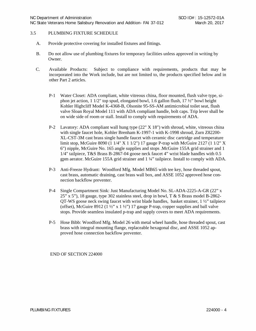
NC Department of Administration NC State Veterans Home Salisbury Renovation and Addition- FAI 37-012
SCO ID#: 15-12572-01A March 20, 2017
PLUMBING FIXTURES 224000 - 4
3.5 PLUMBING FIXTURE SCHEDULE
A. Provide protective covering for installed fixtures and fittings.
B. Do not allow use of plumbing fixtures for temporary facilities unless approved in writing by Owner.
C. Available Products: Subject to compliance with requirements, products that may be incorporated into the Work include, but are not limited to, the products specified below and in other Part 2 articles.
P-1 Water Closet: ADA compliant, white vitreous china, floor mounted, flush valve type, si-
phon jet action, 1 1/2" top spud, elongated bowl, 1.6 gallon flush, 17 ½” bowl height Kohler Highcliff Model K-4368-B, Olsonite 95-SS-AM antimicrobial toilet seat, flush valve Sloan Royal Model 111 with ADA compliant handle, bolt caps. Trip lever shall be on wide side of room or stall. Install to comply with requirements of ADA.
P-2 Lavatory: ADA compliant wall hung type (22" X 18") with shroud, white, vitreous china
with single faucet hole, Kohler Brenham K-1997-1 with K-1998 shroud, Zurn Z82200-XL-CST-3M cast brass single handle faucet with ceramic disc cartridge and temperature limit stop, McGuire 8090 (1 1/4" X 1 1/2") 17 gauge P-trap with McGuire 2127 (1 1/2" X 6") nipple, McGuire No. 165 angle supplies and stops .McGuire 155A grid strainer and 1 1/4" tailpiece, T&S Brass B-2867-04 goose neck faucet 4” wrist blade handles with 0.5 gpm aerator. McGuire 155A grid strainer and 1 ¼” tailpiece. Install to comply with ADA.
P-3 Anti-Freeze Hydrant: Woodford Mfg. Model MB65 with tee key, hose threaded spout,
cast brass, automatic draining, cast brass wall box, and ASSE 1052 approved hose con-nection backflow preventer.
P-4 Single Compartment Sink: Just Manufacturing Model No. SL-ADA-2225-A-GR (22” x
25” x 5”), 18 gauge, type 302 stainless steel, drop in bowl, T & S Brass model B-2862-QT-WS goose neck swing faucet with wrist blade handles, basket strainer, 1 ½” tailpiece (offset), McGuire 8912 (1 ½” x 1 ½”) 17 gauge P-trap, copper supplies and ball valve stops. Provide seamless insulated p-trap and supply covers to meet ADA requirements.
P-5 Hose Bibb: Woodford Mfg. Model 26 with metal wheel handle, hose threaded spout, cast
brass with integral mounting flange, replaceable hexagonal disc, and ASSE 1052 ap-proved hose connection backflow preventer.
END OF SECTION 224000