Embed Size (px)
Citation preview
SECTION 206-09 Vehicle Dynamic Systems
CONTENTS PAGE
DIAGNOSIS AND TESTINGAnti-Lock Control ................................................................................................................................................................ 206-09-2
Principles of Operation ................................................................................................................................................. 206-09-2ABS with Traction Control and Electronic Stability Control (ESC) ......................................................................... 206-09-2Stability Control Sensors ........................................................................................................................................ 206-09-3Steering Sensor ..................................................................................................................................................... 206-09-3
Inspection and Verification ........................................................................................................................................... 206-09-3DTC Charts ................................................................................................................................................................... 206-09-4Symptom Chart ........................................................................................................................................................... 206-09-11Pinpoint Tests ............................................................................................................................................................. 206-09-11
206-09-i Vehicle Dynamic Systems 206-09-i
2011 Mustang, 2/2011
DIAGNOSIS AND TESTINGAnti-Lock ControlSpecial Tool(s)
Backprobe PinsPOM6411 or equivalent
Flex Probe KitNUD105-R025D or equivalent
Fluke 77-IV Digital MultimeterFLU77-4 or equivalent
Rotunda Active Wheel Speed Sensor Tester105-R0110
Vehicle Communication Module (VCM) and Integrated Diagnostic System (IDS) softwarewith appropriate hardware, or equivalent scan tool
Principles of OperationABS with Traction Control and Electronic Stability Control (ESC)The ABS module with traction control manages anti-lock braking to maintain vehicle control and carries out additional functions specific to traction controland Electronic Stability Control (ESC).
ABS OperationWhen the ignition is in the RUN position the ABS module does a preliminary electrical check. At approximately 16 km/h (10 mph), the hydraulic pumpmotor is turned on for approximately one-half second. During this time a buzzing or humming noise may be heard and a vibration may be felt in the brakepedal. This is a normal condition. Any malfunction of the ABS disables the stability assist and illuminates the ABS warning indicator. However, the power-assist braking system functions normally.
The ABS module monitors and compares the rotational speed of each wheel. Wheel speeds are measured by the wheel speed sensor, which electricallysenses each tooth of the sensor ring as it passes through the magnetic field of the sensor. When the ABS module detects an impending wheel lock, the ABSmodule commands the hydraulic pump motor on and the Hydraulic Control Unit (HCU) to open and close the appropriate solenoid valves to modulate the
206-09-2 Vehicle Dynamic Systems 206-09-2
2011 Mustang, 2/2011
brake pressure to the individual brake caliper(s). Once the affected wheel(s) returns to the desired speed, the ABS module commands the HCU to return thesolenoid valves to their normal position, restoring normal base brake operation.
The ABS module must be configured when a new ABS module is installed.
Electronic Brake Distribution (EBD)On initial application of the brake pedal, full pressure is applied to the rear brakes. The ABS module then uses wheel speed input to calculate an estimatedrate of deceleration. Once vehicle deceleration exceeds a predetermined threshold, the ABS module closes the appropriate isolation valves in the HCU tohold the rear brake pressure constant while allowing the front brake pressure to build. This creates a balanced braking condition between the front and rearwheels and minimizes the chance of rear wheel lockup during hard braking. As the vehicle decelerates, the valves are opened to increase the rear brakepressure in proportion to the front brake pressure. A slight bump sensation may be felt in the brake pedal when Electronic Brake Distribution (EBD) isactive. If ABS is disabled due to DTCs being present in the ABS module, EBD continues to function unless the DTCs are for wheel speed sensors or theHCU. When EBD is disabled, the ABS warning indicator, the red brake warning light, stability/traction control indicator (sliding car icon) and the stability/traction control indicator (sliding car icon) off illuminate.
Traction ControlWhen the drive wheels lose traction and begin to spin, with vehicle speed under 108 km/h (67 mph), the ABS module commands the hydraulic pump motoron and the HCU to open and close the appropriate solenoid valves to modulate the brake pressure to the brake caliper(s), and may simultaneously send arequest to the PCM over the High Speed Controller Area Network (HS-CAN) to reduce engine torque to maintain vehicle traction. The PCM accomplishesthis with incremental timing changes and fewer fuel injector pulses until the ABS module ends the request. The request ends when the driven wheel speedreturns to the desired speed. After the vehicle speed exceeds 108 km/h (67 mph), traction control is accomplished using only the PCM torque controlfunction. The traction control system can be deactivated by pressing the traction control switch in the instrument panel.
Electronic Stability Control (ESC)The ESC system constantly monitors the vehicle motion relative to the intended course. This is done by using the yaw rate and lateral accelerometer sensorsto compare the steering input with that of the actual vehicle motion. The ESC system monitors information from the Throttle Position (TP) sensor, thesteering wheel rotation sensor (steering wheel angle and rate of change) a yaw rate sensor and lateral accelerometer sensor which is integral to the RestraintsControl Module (RCM) and measures changes in vehicle direction. If the ESC system determines from all these inputs that the vehicle is unable to travel inthe intended direction, the system adjusts the brake torque at specific wheels in response to direct measurement of the vehicle motion and reduces enginetorque to allow the vehicle to follow the intended course.
Traction Control SwitchThe traction control switch is hardwired to the Instrument Panel Cluster (IPC). The IPC communicates switch status to the ABS module via the HS-CAN.The traction control switch allows the driver to control the use of the traction control and ESC systems. Traction control system status is indicated by thestability/traction control indicator (sliding car icon) off in the IPC. The ESC system automatically restores to full functionality when the ignition is cycledfrom OFF to RUN.
Stability Control SensorsThe stability control sensors for the ESC system include the yaw rate sensor and the lateral accelerometer. The yaw rate sensor and the lateral accelerometerare able to detect and measure changes in vehicle direction that indicate the need for the ABS to make corrections that help prevent vehicle roll over or spinouts. The sensors are housed in the RCM which sends sensor information to the ABS module over the Controller Area Network (CAN). Install a new RCMif any of the sensors are damaged.
Steering SensorThe steering sensor is used by the Power Steering Control Module (PSCM) to determine speed and direction of the steering wheel. This information istransmitted to the ABS module along the HS-CAN. The sensor is attached to the Electronic Power Assist Steering (EPAS) column assembly and is notserviced separately.
ABS Module CalibrationWhen a new ABS module, HCU, or RCM is installed, the ABS module must be calibrated. The calibration procedure is required for the ABS module tolearn the zero-position of the various ESC sensors and components.
If a DTC(s) sets for any component of the ESC system, correct the fault condition and clear the DTC before carrying out the calibration procedure. The needto calibrate the ABS module is also indicated by the stability/traction control indicator (sliding car icon) in the IPC flashing once every 2 seconds. Theindicator flashes after clearing the DTCs associated with the ESC systems.
To calibrate the ABS module, carry out the IVD Initialization sequence using the scan tool.
If a DTC is retrieved after calibration, refer to the ABS Module DTC Chart in this section.
Inspection and Verification1. Verify the customer concern.
2. Verify the stoplamps operate correctly. If the stoplamps do not operate correctly, refer to Section 417-01. If the stoplamps operate correctly, proceedto the next step.
3. Verify the base brake system operates correctly. If any concerns are present, address them before continuing with any ABS concerns. Refer to Section206-00. If the base brake system operates correctly, proceed to the next step.
4. Visually inspect for obvious signs of mechanical or electrical damage.
206-09-3 Vehicle Dynamic Systems 206-09-3DIAGNOSIS AND TESTING (Continued)
2011 Mustang, 2/2011
Visual Inspection Chart
Mechanical Electrical
• Base brake system• Hydraulic Control Unit (HCU)• Tire pressure• Mismatched tires• Wheel speed sensor ring
• ABS module• Battery Junction Box (BJB) fuse(s):
— 8 (40A)— 10 (30A)
• Smart Junction Box (SJB) fuse 34 (5A)• Brake Pedal Position (BPP) switch• Traction control switch• Wheel speed sensor• Wiring, terminals or connectors
5. If an obvious cause for an observed or reported concern is found, correct the cause (if possible) before proceeding to the next step.
6. NOTE: Make sure to use the latest scan tool software release.
If the cause is not visually evident, connect the scan tool to the Data Link Connector (DLC).
7. NOTE: The Vehicle Communication Module (VCM) LED prove-out confirms power and ground from the DLC are provided to the VCM.
If the scan tool does not communicate with the VCM:
• check the VCM connection to the vehicle.
• check the scan tool connection to the VCM.
• refer to Section 418-00, No Power To The Scan Tool, to diagnose no power to the scan tool.
8. If the scan tool does not communicate with the vehicle:
• verify the ignition is ON.
• verify the scan tool operation with a known good vehicle.
• refer to Section 418-00, The PCM Does Not Respond To The Scan Tool, to diagnose no response from the PCM.
9. Carry out the network test.
• If the scan tool responds with no communication for one or more modules, refer to Section 418-00.
• If the network test passes, retrieve and record Continuous Memory Diagnostic Trouble Codes (CMDTCs).
10. Clear the CMDTCs and carry out the self-test diagnostics for the ABS module and the IPC.
11. If the DTCs retrieved are related to the concern, go to the ABS Module DTC Chart. For all other DTCs, refer to Section 419-10.
12. If no DTCs related to the concern are retrieved, GO to Symptom Chart.
DTC Charts
NOTE: This module utilizes a 5-character DTC followed by a 2-character failure type code. The failure type code provides information about specific faultconditions such as opens or shorts to ground. Continuous Memory Diagnostic Trouble Codes (CMDTCs) have an additional 2-character DTC status codesuffix to assist in determining DTC history.
ABS Module DTC Chart
DTC Description Action
B11E8:16 ABS Power Supply: Circuit Voltage Below Threshold GO to Pinpoint Test A.
B11E8:17 ABS Power Supply: Circuit Voltage Above Threshold GO to Pinpoint Test B.
C0001:11 TCS Control Channel "A" Valve 1: Circuit Short to Ground This DTC indicates that part of the ABS module has failedinternally. CLEAR the DTCs. REPEAT the self-test. If DTCC0001:11 returns, INSTALL a new ABS module. REFER toAnti-Lock Brake System (ABS) Module in this section. TESTthe system for normal operation.
C0001:12 TCS Control Channel "A" Valve 1: Circuit Short to Battery This DTC indicates that part of the ABS module has failedinternally. CLEAR the DTCs. REPEAT the self-test. If DTCC0001:12 returns, INSTALL a new ABS module. REFER toAnti-Lock Brake System (ABS) Module in this section. TESTthe system for normal operation.
206-09-4 Vehicle Dynamic Systems 206-09-4DIAGNOSIS AND TESTING (Continued)
2011 Mustang, 2/2011
ABS Module DTC Chart (Continued)DTC Description Action
C0001:13 TCS Control Channel "A" Valve 1: Circuit Open This DTC indicates that part of the ABS module has failedinternally. CLEAR the DTCs. REPEAT the self-test. If DTCC0001:13 returns, INSTALL a new ABS module. REFER toAnti-Lock Brake System (ABS) Module in this section. TESTthe system for normal operation.
C0002:11 TCS Control Channel "A" Valve 2: Circuit Short to Ground This DTC indicates that part of the ABS module has failedinternally. CLEAR the DTCs. REPEAT the self-test. If DTCC0002:11 returns, INSTALL a new ABS module. REFER toAnti-Lock Brake System (ABS) Module in this section. TESTthe system for normal operation.
C0002:12 TCS Control Channel "A" Valve 2: Circuit Short to Battery This DTC indicates that part of the ABS module has failedinternally. CLEAR the DTCs. REPEAT the self-test. If DTCC0002:12 returns, INSTALL a new ABS module. REFER toAnti-Lock Brake System (ABS) Module in this section. TESTthe system for normal operation.
C0002:13 TCS Control Channel "A" Valve 2: Circuit Open This DTC indicates that part of the ABS module has failedinternally. CLEAR the DTCs. REPEAT the self-test. If DTCC0002:13 returns, INSTALL a new ABS module. REFER toAnti-Lock Brake System (ABS) Module in this section. TESTthe system for normal operation.
C0003:11 TCS Control Channel "B" Valve 1: Circuit Short to Ground This DTC indicates that part of the ABS module has failedinternally. CLEAR the DTCs. REPEAT the self-test. If DTCC0003:11 returns, INSTALL a new ABS module. REFER toAnti-Lock Brake System (ABS) Module in this section. TESTthe system for normal operation.
C0003:12 TCS Control Channel "B" Valve 1: Circuit Short to Battery This DTC indicates that part of the ABS module has failedinternally. CLEAR the DTCs. REPEAT the self-test. If DTCC0003:12 returns, INSTALL a new ABS module. REFER toAnti-Lock Brake System (ABS) Module in this section. TESTthe system for normal operation.
C0003:13 TCS Control Channel "B" Valve 1: Circuit Open This DTC indicates that part of the ABS module has failedinternally. CLEAR the DTCs. REPEAT the self-test. If DTCC0003:13 returns, INSTALL a new ABS module. REFER toAnti-Lock Brake System (ABS) Module in this section. TESTthe system for normal operation.
C0004:11 TCS Control Channel "B" Valve 2: Circuit Short to Ground This DTC indicates that part of the ABS module has failedinternally. CLEAR the DTCs. REPEAT the self-test. If DTCC0004:11 returns, INSTALL a new ABS module. REFER toAnti-Lock Brake System (ABS) Module in this section. TESTthe system for normal operation.
C0004:12 TCS Control Channel "B" Valve 2: Circuit Short to Battery This DTC indicates that part of the ABS module has failedinternally. CLEAR the DTCs. REPEAT the self-test. If DTCC0004:12 returns, INSTALL a new ABS module. REFER toAnti-Lock Brake System (ABS) Module in this section. TESTthe system for normal operation.
C0004:13 TCS Control Channel "B" Valve 2: Circuit Open This DTC indicates that part of the ABS module has failedinternally. CLEAR the DTCs. REPEAT the self-test. If DTCC0004:13 returns, INSTALL a new ABS module. REFER toAnti-Lock Brake System (ABS) Module in this section. TESTthe system for normal operation.
C0020:12 ABS Pump Motor Control: Circuit Short To Battery GO to Pinpoint Test C.
C0020:15 ABS Pump Motor Control: Circuit Short To Battery Or Open GO to Pinpoint Test C.
C0020:71 ABS Pump Motor Control: Actuator Stuck GO to Pinpoint Test C.
C0031:13 Left Front Wheel Speed Sensor: Circuit Open GO to Pinpoint Test D.
C0031:17 Left Front Wheel Speed Sensor: Circuit Voltage AboveThreshold
GO to Pinpoint Test D.
C0031:23 Left Front Wheel Speed Sensor: Signal Stuck Low GO to Pinpoint Test D.
C0031:2F Left Front Wheel Speed Sensor: Signal Erratic GO to Pinpoint Test E.
C0031:62 Left Front Wheel Speed Sensor: Signal Compare Failure GO to Pinpoint Test E.
C0034:13 Right Front Wheel Speed Sensor: Circuit Open GO to Pinpoint Test D.
C0034:17 Right Front Wheel Speed Sensor: Circuit Above Threshold GO to Pinpoint Test D.
C0034:23 Right Front Wheel Speed Sensor: Signal Stuck Low GO to Pinpoint Test D.
206-09-5 Vehicle Dynamic Systems 206-09-5DIAGNOSIS AND TESTING (Continued)
2011 Mustang, 2/2011
ABS Module DTC Chart (Continued)DTC Description Action
C0034:2F Right Front Wheel Speed Sensor: Signal Erratic GO to Pinpoint Test E.
C0034:62 Right Front Wheel Speed Sensor: Signal Compare Failure GO to Pinpoint Test E.
C0037:13 Left Rear Wheel Speed Sensor: Circuit Open GO to Pinpoint Test D.
C0037:17 Left Rear Wheel Speed Sensor: Circuit Voltage AboveThreshold
GO to Pinpoint Test D.
C0037:23 Left Rear Wheel Speed Sensor: Signal Stuck Low GO to Pinpoint Test D.
C0037:2F Left Rear Wheel Speed Sensor: Signal Erratic GO to Pinpoint Test E.
C0037:62 Left Rear Wheel Speed Sensor: Signal Compare Failure GO to Pinpoint Test E.
C003A:13 Right Rear Wheel Speed Sensor: Circuit Open GO to Pinpoint Test D.
C003A:17 Right Rear Wheel Speed Sensor: Circuit Voltage AboveThreshold
GO to Pinpoint Test D.
C003A:23 Right Rear Wheel Speed Sensor: Signal Stuck Low GO to Pinpoint Test D.
C003A:2F Right Rear Wheel Speed Sensor: Signal Erratic GO to Pinpoint Test E.
C003A:62 Right Rear Wheel Speed Sensor Signal Compare Failure GO to Pinpoint Test E.
C0040:72 Brake Pedal Switch "A": Actuator Stuck Open GO to Pinpoint Test F.
C0040:73 Brake Pedal Switch "A": Actuator Stuck Closed GO to Pinpoint Test F.
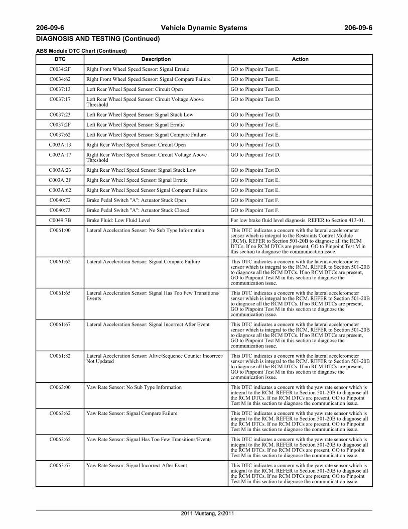
C0049:7B Brake Fluid: Low Fluid Level For low brake fluid level diagnosis. REFER to Section 413-01.
C0061:00 Lateral Acceleration Sensor: No Sub Type Information This DTC indicates a concern with the lateral accelerometersensor which is integral to the Restraints Control Module(RCM). REFER to Section 501-20B to diagnose all the RCMDTCs. If no RCM DTCs are present, GO to Pinpoint Test M inthis section to diagnose the communication issue.
C0061:62 Lateral Acceleration Sensor: Signal Compare Failure This DTC indicates a concern with the lateral accelerometersensor which is integral to the RCM. REFER to Section 501-20Bto diagnose all the RCM DTCs. If no RCM DTCs are present,GO to Pinpoint Test M in this section to diagnose thecommunication issue.
C0061:65 Lateral Acceleration Sensor: Signal Has Too Few Transitions/Events
This DTC indicates a concern with the lateral accelerometersensor which is integral to the RCM. REFER to Section 501-20Bto diagnose all the RCM DTCs. If no RCM DTCs are present,GO to Pinpoint Test M in this section to diagnose thecommunication issue.
C0061:67 Lateral Acceleration Sensor: Signal Incorrect After Event This DTC indicates a concern with the lateral accelerometersensor which is integral to the RCM. REFER to Section 501-20Bto diagnose all the RCM DTCs. If no RCM DTCs are present,GO to Pinpoint Test M in this section to diagnose thecommunication issue.
C0061:82 Lateral Acceleration Sensor: Alive/Sequence Counter Incorrect/Not Updated
This DTC indicates a concern with the lateral accelerometersensor which is integral to the RCM. REFER to Section 501-20Bto diagnose all the RCM DTCs. If no RCM DTCs are present,GO to Pinpoint Test M in this section to diagnose thecommunication issue.
C0063:00 Yaw Rate Sensor: No Sub Type Information This DTC indicates a concern with the yaw rate sensor which isintegral to the RCM. REFER to Section 501-20B to diagnose allthe RCM DTCs. If no RCM DTCs are present, GO to PinpointTest M in this section to diagnose the communication issue.
C0063:62 Yaw Rate Sensor: Signal Compare Failure This DTC indicates a concern with the yaw rate sensor which isintegral to the RCM. REFER to Section 501-20B to diagnose allthe RCM DTCs. If no RCM DTCs are present, GO to PinpointTest M in this section to diagnose the communication issue.
C0063:65 Yaw Rate Sensor: Signal Has Too Few Transitions/Events This DTC indicates a concern with the yaw rate sensor which isintegral to the RCM. REFER to Section 501-20B to diagnose allthe RCM DTCs. If no RCM DTCs are present, GO to PinpointTest M in this section to diagnose the communication issue.
C0063:67 Yaw Rate Sensor: Signal Incorrect After Event This DTC indicates a concern with the yaw rate sensor which isintegral to the RCM. REFER to Section 501-20B to diagnose allthe RCM DTCs. If no RCM DTCs are present, GO to PinpointTest M in this section to diagnose the communication issue.
206-09-6 Vehicle Dynamic Systems 206-09-6DIAGNOSIS AND TESTING (Continued)
2011 Mustang, 2/2011
ABS Module DTC Chart (Continued)DTC Description Action
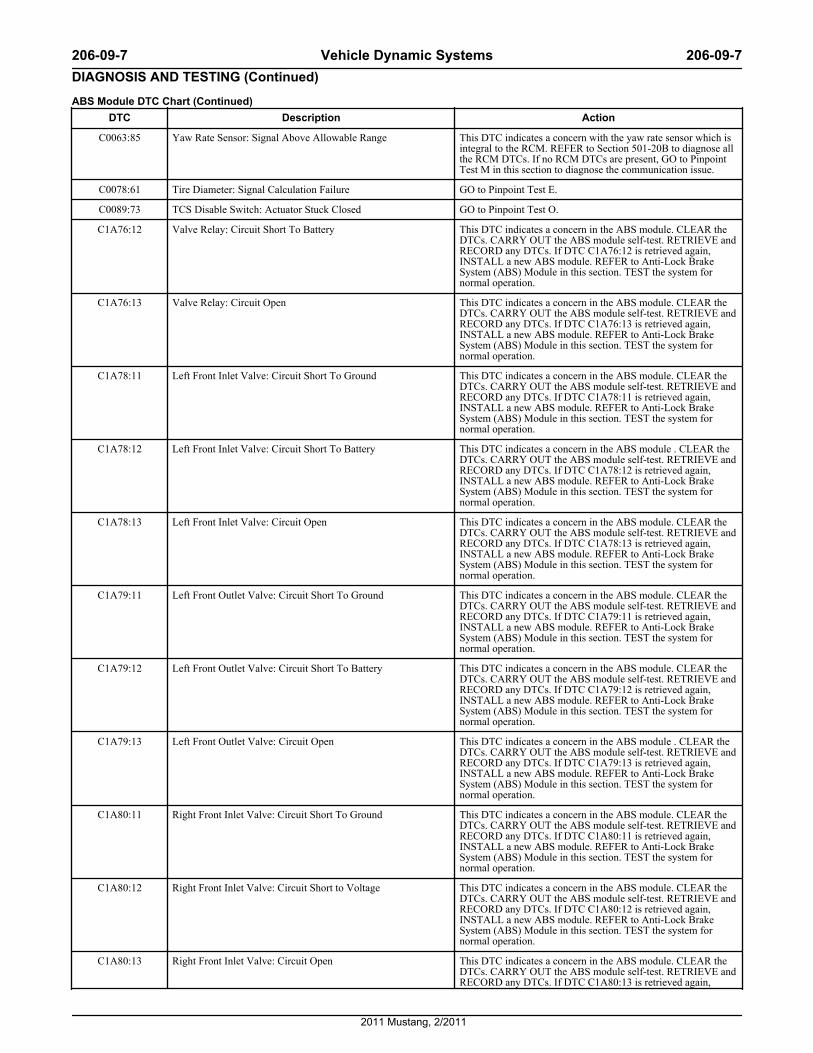
C0063:85 Yaw Rate Sensor: Signal Above Allowable Range This DTC indicates a concern with the yaw rate sensor which isintegral to the RCM. REFER to Section 501-20B to diagnose allthe RCM DTCs. If no RCM DTCs are present, GO to PinpointTest M in this section to diagnose the communication issue.
C0078:61 Tire Diameter: Signal Calculation Failure GO to Pinpoint Test E.
C0089:73 TCS Disable Switch: Actuator Stuck Closed GO to Pinpoint Test O.
C1A76:12 Valve Relay: Circuit Short To Battery This DTC indicates a concern in the ABS module. CLEAR theDTCs. CARRY OUT the ABS module self-test. RETRIEVE andRECORD any DTCs. If DTC C1A76:12 is retrieved again,INSTALL a new ABS module. REFER to Anti-Lock BrakeSystem (ABS) Module in this section. TEST the system fornormal operation.
C1A76:13 Valve Relay: Circuit Open This DTC indicates a concern in the ABS module. CLEAR theDTCs. CARRY OUT the ABS module self-test. RETRIEVE andRECORD any DTCs. If DTC C1A76:13 is retrieved again,INSTALL a new ABS module. REFER to Anti-Lock BrakeSystem (ABS) Module in this section. TEST the system fornormal operation.
C1A78:11 Left Front Inlet Valve: Circuit Short To Ground This DTC indicates a concern in the ABS module. CLEAR theDTCs. CARRY OUT the ABS module self-test. RETRIEVE andRECORD any DTCs. If DTC C1A78:11 is retrieved again,INSTALL a new ABS module. REFER to Anti-Lock BrakeSystem (ABS) Module in this section. TEST the system fornormal operation.
C1A78:12 Left Front Inlet Valve: Circuit Short To Battery This DTC indicates a concern in the ABS module . CLEAR theDTCs. CARRY OUT the ABS module self-test. RETRIEVE andRECORD any DTCs. If DTC C1A78:12 is retrieved again,INSTALL a new ABS module. REFER to Anti-Lock BrakeSystem (ABS) Module in this section. TEST the system fornormal operation.
C1A78:13 Left Front Inlet Valve: Circuit Open This DTC indicates a concern in the ABS module. CLEAR theDTCs. CARRY OUT the ABS module self-test. RETRIEVE andRECORD any DTCs. If DTC C1A78:13 is retrieved again,INSTALL a new ABS module. REFER to Anti-Lock BrakeSystem (ABS) Module in this section. TEST the system fornormal operation.
C1A79:11 Left Front Outlet Valve: Circuit Short To Ground This DTC indicates a concern in the ABS module. CLEAR theDTCs. CARRY OUT the ABS module self-test. RETRIEVE andRECORD any DTCs. If DTC C1A79:11 is retrieved again,INSTALL a new ABS module. REFER to Anti-Lock BrakeSystem (ABS) Module in this section. TEST the system fornormal operation.
C1A79:12 Left Front Outlet Valve: Circuit Short To Battery This DTC indicates a concern in the ABS module. CLEAR theDTCs. CARRY OUT the ABS module self-test. RETRIEVE andRECORD any DTCs. If DTC C1A79:12 is retrieved again,INSTALL a new ABS module. REFER to Anti-Lock BrakeSystem (ABS) Module in this section. TEST the system fornormal operation.
C1A79:13 Left Front Outlet Valve: Circuit Open This DTC indicates a concern in the ABS module . CLEAR theDTCs. CARRY OUT the ABS module self-test. RETRIEVE andRECORD any DTCs. If DTC C1A79:13 is retrieved again,INSTALL a new ABS module. REFER to Anti-Lock BrakeSystem (ABS) Module in this section. TEST the system fornormal operation.
C1A80:11 Right Front Inlet Valve: Circuit Short To Ground This DTC indicates a concern in the ABS module. CLEAR theDTCs. CARRY OUT the ABS module self-test. RETRIEVE andRECORD any DTCs. If DTC C1A80:11 is retrieved again,INSTALL a new ABS module. REFER to Anti-Lock BrakeSystem (ABS) Module in this section. TEST the system fornormal operation.
C1A80:12 Right Front Inlet Valve: Circuit Short to Voltage This DTC indicates a concern in the ABS module. CLEAR theDTCs. CARRY OUT the ABS module self-test. RETRIEVE andRECORD any DTCs. If DTC C1A80:12 is retrieved again,INSTALL a new ABS module. REFER to Anti-Lock BrakeSystem (ABS) Module in this section. TEST the system fornormal operation.
C1A80:13 Right Front Inlet Valve: Circuit Open This DTC indicates a concern in the ABS module. CLEAR theDTCs. CARRY OUT the ABS module self-test. RETRIEVE andRECORD any DTCs. If DTC C1A80:13 is retrieved again,
206-09-7 Vehicle Dynamic Systems 206-09-7DIAGNOSIS AND TESTING (Continued)
2011 Mustang, 2/2011
ABS Module DTC Chart (Continued)DTC Description Action
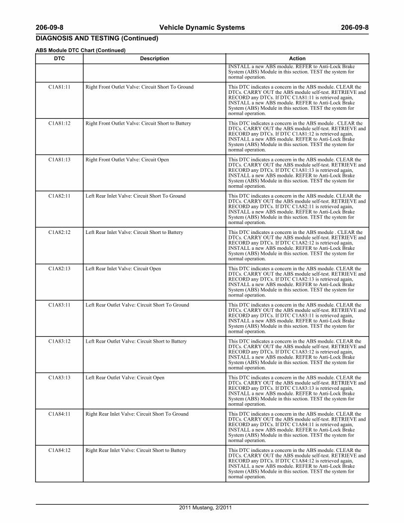
INSTALL a new ABS module. REFER to Anti-Lock BrakeSystem (ABS) Module in this section. TEST the system fornormal operation.
C1A81:11 Right Front Outlet Valve: Circuit Short To Ground This DTC indicates a concern in the ABS module. CLEAR theDTCs. CARRY OUT the ABS module self-test. RETRIEVE andRECORD any DTCs. If DTC C1A81:11 is retrieved again,INSTALL a new ABS module. REFER to Anti-Lock BrakeSystem (ABS) Module in this section. TEST the system fornormal operation.
C1A81:12 Right Front Outlet Valve: Circuit Short to Battery This DTC indicates a concern in the ABS module . CLEAR theDTCs. CARRY OUT the ABS module self-test. RETRIEVE andRECORD any DTCs. If DTC C1A81:12 is retrieved again,INSTALL a new ABS module. REFER to Anti-Lock BrakeSystem (ABS) Module in this section. TEST the system fornormal operation.
C1A81:13 Right Front Outlet Valve: Circuit Open This DTC indicates a concern in the ABS module. CLEAR theDTCs. CARRY OUT the ABS module self-test. RETRIEVE andRECORD any DTCs. If DTC C1A81:13 is retrieved again,INSTALL a new ABS module. REFER to Anti-Lock BrakeSystem (ABS) Module in this section. TEST the system fornormal operation.
C1A82:11 Left Rear Inlet Valve: Circuit Short To Ground This DTC indicates a concern in the ABS module. CLEAR theDTCs. CARRY OUT the ABS module self-test. RETRIEVE andRECORD any DTCs. If DTC C1A82:11 is retrieved again,INSTALL a new ABS module. REFER to Anti-Lock BrakeSystem (ABS) Module in this section. TEST the system fornormal operation.
C1A82:12 Left Rear Inlet Valve: Circuit Short to Battery This DTC indicates a concern in the ABS module . CLEAR theDTCs. CARRY OUT the ABS module self-test. RETRIEVE andRECORD any DTCs. If DTC C1A82:12 is retrieved again,INSTALL a new ABS module. REFER to Anti-Lock BrakeSystem (ABS) Module in this section. TEST the system fornormal operation.
C1A82:13 Left Rear Inlet Valve: Circuit Open This DTC indicates a concern in the ABS module. CLEAR theDTCs. CARRY OUT the ABS module self-test. RETRIEVE andRECORD any DTCs. If DTC C1A82:13 is retrieved again,INSTALL a new ABS module. REFER to Anti-Lock BrakeSystem (ABS) Module in this section. TEST the system fornormal operation.
C1A83:11 Left Rear Outlet Valve: Circuit Short To Ground This DTC indicates a concern in the ABS module. CLEAR theDTCs. CARRY OUT the ABS module self-test. RETRIEVE andRECORD any DTCs. If DTC C1A83:11 is retrieved again,INSTALL a new ABS module. REFER to Anti-Lock BrakeSystem (ABS) Module in this section. TEST the system fornormal operation.
C1A83:12 Left Rear Outlet Valve: Circuit Short to Battery This DTC indicates a concern in the ABS module. CLEAR theDTCs. CARRY OUT the ABS module self-test. RETRIEVE andRECORD any DTCs. If DTC C1A83:12 is retrieved again,INSTALL a new ABS module. REFER to Anti-Lock BrakeSystem (ABS) Module in this section. TEST the system fornormal operation.
C1A83:13 Left Rear Outlet Valve: Circuit Open This DTC indicates a concern in the ABS module. CLEAR theDTCs. CARRY OUT the ABS module self-test. RETRIEVE andRECORD any DTCs. If DTC C1A83:13 is retrieved again,INSTALL a new ABS module. REFER to Anti-Lock BrakeSystem (ABS) Module in this section. TEST the system fornormal operation.
C1A84:11 Right Rear Inlet Valve: Circuit Short To Ground This DTC indicates a concern in the ABS module. CLEAR theDTCs. CARRY OUT the ABS module self-test. RETRIEVE andRECORD any DTCs. If DTC C1A84:11 is retrieved again,INSTALL a new ABS module. REFER to Anti-Lock BrakeSystem (ABS) Module in this section. TEST the system fornormal operation.
C1A84:12 Right Rear Inlet Valve: Circuit Short to Battery This DTC indicates a concern in the ABS module. CLEAR theDTCs. CARRY OUT the ABS module self-test. RETRIEVE andRECORD any DTCs. If DTC C1A84:12 is retrieved again,INSTALL a new ABS module. REFER to Anti-Lock BrakeSystem (ABS) Module in this section. TEST the system fornormal operation.
206-09-8 Vehicle Dynamic Systems 206-09-8DIAGNOSIS AND TESTING (Continued)
2011 Mustang, 2/2011
ABS Module DTC Chart (Continued)DTC Description Action
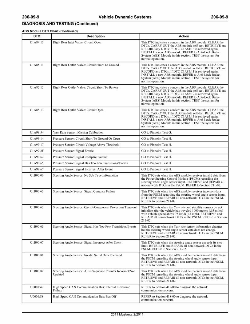
C1A84:13 Right Rear Inlet Valve: Circuit Open This DTC indicates a concern in the ABS module. CLEAR theDTCs. CARRY OUT the ABS module self-test. RETRIEVE andRECORD any DTCs. If DTC C1A84:13 is retrieved again,INSTALL a new ABS module. REFER to Anti-Lock BrakeSystem (ABS) Module in this section. TEST the system fornormal operation.
C1A85:11 Right Rear Outlet Valve: Circuit Short To Ground This DTC indicates a concern in the ABS module. CLEAR theDTCs. CARRY OUT the ABS module self-test. RETRIEVE andRECORD any DTCs. If DTC C1A85:11 is retrieved again,INSTALL a new ABS module. REFER to Anti-Lock BrakeSystem (ABS) Module in this section. TEST the system fornormal operation.
C1A85:12 Right Rear Outlet Valve: Circuit Short To Battery This DTC indicates a concern in the ABS module. CLEAR theDTCs. CARRY OUT the ABS module self-test. RETRIEVE andRECORD any DTCs. If DTC C1A85:12 is retrieved again,INSTALL a new ABS module. REFER to Anti-Lock BrakeSystem (ABS) Module in this section. TEST the system fornormal operation.
C1A85:13 Right Rear Outlet Valve: Circuit Open This DTC indicates a concern in the ABS module. CLEAR theDTCs. CARRY OUT the ABS module self-test. RETRIEVE andRECORD any DTCs. If DTC C1A85:13 is retrieved again,INSTALL a new ABS module. REFER to Anti-Lock BrakeSystem (ABS) Module in this section. TEST the system fornormal operation.
C1A98:54 Yaw Rate Sensor: Missing Calibration GO to Pinpoint Test G.
C1A99:14 Pressure Sensor: Circuit Short To Ground Or Open GO to Pinpoint Test H.
C1A99:17 Pressure Sensor: Circuit Voltage Above Threshold GO to Pinpoint Test H.
C1A99:2F Pressure Sensor: Signal Erratic GO to Pinpoint Test H.
C1A99:62 Pressure Sensor: Signal Compare Failure GO to Pinpoint Test H.
C1A99:65 Pressure Sensor: Signal Has Too Few Transitions/Events GO to Pinpoint Test H.
C1A99:67 Pressure Sensor: Signal Incorrect After Event GO to Pinpoint Test H.
C1B00:00 Steering Angle Sensor: No Sub Type Information This DTC sets when the ABS module receives invalid data fromthe Power Steering Control Module (PSCM) regarding thesteering wheel angle sensor input. RETRIEVE and REPAIR allnon-network DTCs in the PSCM. REFER to Section 211-02.
C1B00:62 Steering Angle Sensor: Signal Compare Failure This DTC sets when the ABS module receives incorrect datafrom the PSCM regarding the steering wheel angle sensor input.RETRIEVE and REPAIR all non-network DTCs in the PSCM.REFER to Section 211-02.
C1B00:63 Steering Angle Sensor: Circuit/Component Protection Time-out This DTC sets when the Yaw rate and stability sensors do notinitialize after the vehicle has traveled 1000 meters (.65 miles)with vehicle speed above 75 km/h (45 mph). RETRIEVE andREPAIR all non-network DTCs in the PSCM. REFER to Section211-02.
C1B00:65 Steering Angle Sensor: Signal Has Too Few Transitions/Events This DTC sets when the Yaw rate sensor information changesbut the steering wheel angle sensor data does not change.RETRIEVE and REPAIR all non-network DTCs in the PSCM.REFER to Section 211-02.
C1B00:67 Steering Angle Sensor: Signal Incorrect After Event This DTC sets when the steering angle sensor exceeds its steplimit. RETRIEVE and REPAIR all non-network DTCs in thePSCM. REFER to Section 211-02.
C1B00:81 Steering Angle Sensor: Invalid Serial Data Received This DTC sets when the ABS module receives invalid data fromthe PSCM regarding the steering wheel angle sensor input.RETRIEVE and REPAIR all non-network DTCs in the PSCM.REFER to Section 211-02.
C1B00:82 Steering Angle Sensor: Alive/Sequence Counter Incorrect/NotUpdated
This DTC sets when the ABS module receives invalid data fromthe PSCM regarding the steering wheel angle sensor input.RETRIEVE and REPAIR all non-network DTCs in the PSCM.REFER to Section 211-02.
U0001:49 High Speed CAN Communication Bus: Internal ElectronicFailure
REFER to Section 418-00 to diagnose the networkcommunication concern.
U0001:88 High Speed CAN Communication Bus: Bus Off REFER to Section 418-00 to diagnose the networkcommunication concern.
206-09-9 Vehicle Dynamic Systems 206-09-9DIAGNOSIS AND TESTING (Continued)
2011 Mustang, 2/2011
ABS Module DTC Chart (Continued)DTC Description Action
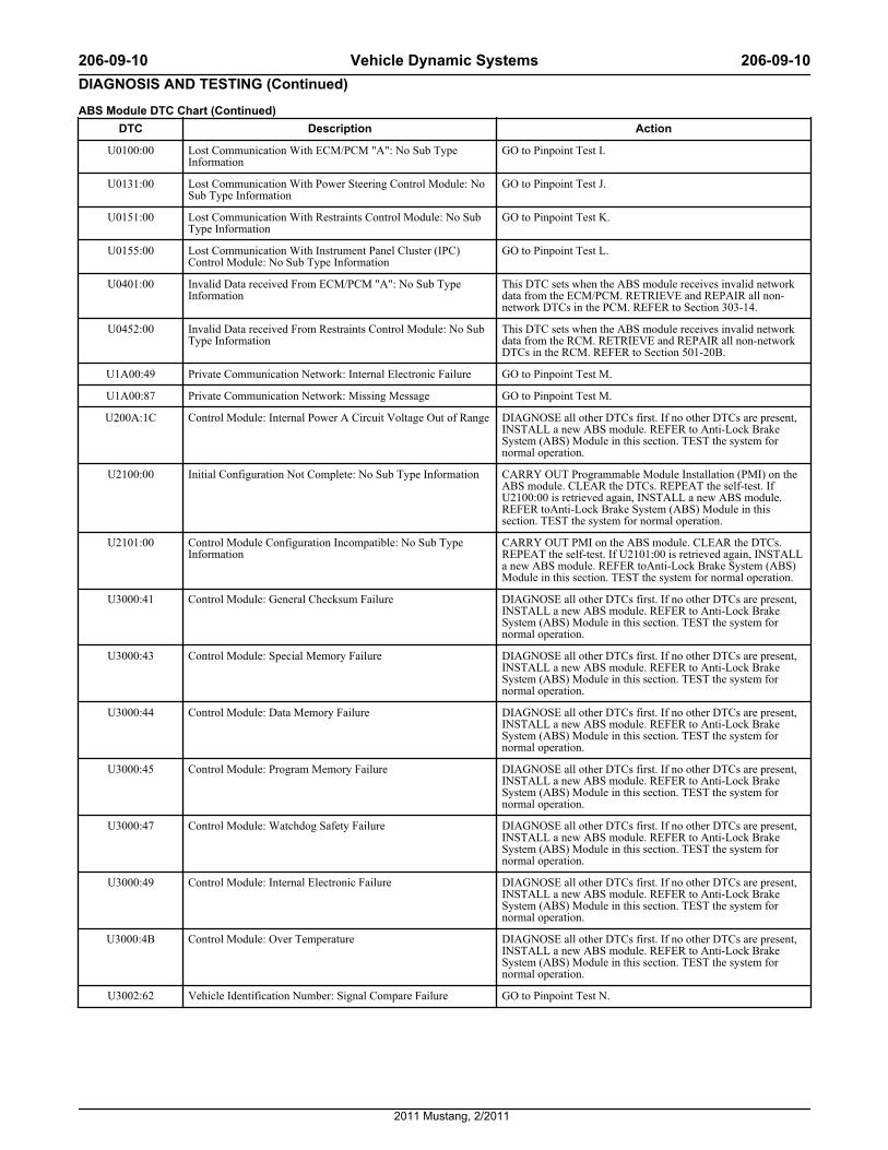
U0100:00 Lost Communication With ECM/PCM "A": No Sub TypeInformation
GO to Pinpoint Test I.
U0131:00 Lost Communication With Power Steering Control Module: NoSub Type Information
GO to Pinpoint Test J.
U0151:00 Lost Communication With Restraints Control Module: No SubType Information
GO to Pinpoint Test K.
U0155:00 Lost Communication With Instrument Panel Cluster (IPC)Control Module: No Sub Type Information
GO to Pinpoint Test L.
U0401:00 Invalid Data received From ECM/PCM "A": No Sub TypeInformation
This DTC sets when the ABS module receives invalid networkdata from the ECM/PCM. RETRIEVE and REPAIR all non-network DTCs in the PCM. REFER to Section 303-14.
U0452:00 Invalid Data received From Restraints Control Module: No SubType Information
This DTC sets when the ABS module receives invalid networkdata from the RCM. RETRIEVE and REPAIR all non-networkDTCs in the RCM. REFER to Section 501-20B.
U1A00:49 Private Communication Network: Internal Electronic Failure GO to Pinpoint Test M.
U1A00:87 Private Communication Network: Missing Message GO to Pinpoint Test M.
U200A:1C Control Module: Internal Power A Circuit Voltage Out of Range DIAGNOSE all other DTCs first. If no other DTCs are present,INSTALL a new ABS module. REFER to Anti-Lock BrakeSystem (ABS) Module in this section. TEST the system fornormal operation.
U2100:00 Initial Configuration Not Complete: No Sub Type Information CARRY OUT Programmable Module Installation (PMI) on theABS module. CLEAR the DTCs. REPEAT the self-test. IfU2100:00 is retrieved again, INSTALL a new ABS module.REFER toAnti-Lock Brake System (ABS) Module in thissection. TEST the system for normal operation.
U2101:00 Control Module Configuration Incompatible: No Sub TypeInformation
CARRY OUT PMI on the ABS module. CLEAR the DTCs.REPEAT the self-test. If U2101:00 is retrieved again, INSTALLa new ABS module. REFER toAnti-Lock Brake System (ABS)Module in this section. TEST the system for normal operation.
U3000:41 Control Module: General Checksum Failure DIAGNOSE all other DTCs first. If no other DTCs are present,INSTALL a new ABS module. REFER to Anti-Lock BrakeSystem (ABS) Module in this section. TEST the system fornormal operation.
U3000:43 Control Module: Special Memory Failure DIAGNOSE all other DTCs first. If no other DTCs are present,INSTALL a new ABS module. REFER to Anti-Lock BrakeSystem (ABS) Module in this section. TEST the system fornormal operation.
U3000:44 Control Module: Data Memory Failure DIAGNOSE all other DTCs first. If no other DTCs are present,INSTALL a new ABS module. REFER to Anti-Lock BrakeSystem (ABS) Module in this section. TEST the system fornormal operation.
U3000:45 Control Module: Program Memory Failure DIAGNOSE all other DTCs first. If no other DTCs are present,INSTALL a new ABS module. REFER to Anti-Lock BrakeSystem (ABS) Module in this section. TEST the system fornormal operation.
U3000:47 Control Module: Watchdog Safety Failure DIAGNOSE all other DTCs first. If no other DTCs are present,INSTALL a new ABS module. REFER to Anti-Lock BrakeSystem (ABS) Module in this section. TEST the system fornormal operation.
U3000:49 Control Module: Internal Electronic Failure DIAGNOSE all other DTCs first. If no other DTCs are present,INSTALL a new ABS module. REFER to Anti-Lock BrakeSystem (ABS) Module in this section. TEST the system fornormal operation.
U3000:4B Control Module: Over Temperature DIAGNOSE all other DTCs first. If no other DTCs are present,INSTALL a new ABS module. REFER to Anti-Lock BrakeSystem (ABS) Module in this section. TEST the system fornormal operation.
U3002:62 Vehicle Identification Number: Signal Compare Failure GO to Pinpoint Test N.
206-09-10 Vehicle Dynamic Systems 206-09-10DIAGNOSIS AND TESTING (Continued)
2011 Mustang, 2/2011
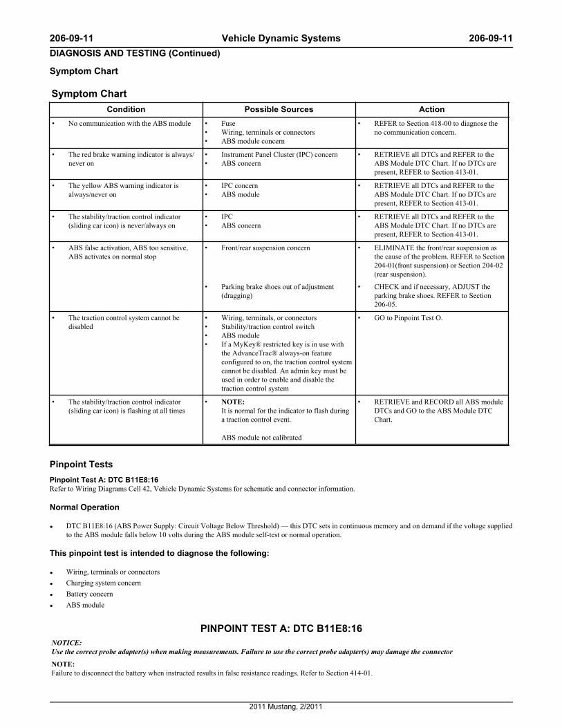
Symptom Chart
Symptom ChartCondition Possible Sources Action
• No communication with the ABS module • Fuse• Wiring, terminals or connectors• ABS module concern
• REFER to Section 418-00 to diagnose theno communication concern.
• The red brake warning indicator is always/never on
• Instrument Panel Cluster (IPC) concern• ABS concern
• RETRIEVE all DTCs and REFER to theABS Module DTC Chart. If no DTCs arepresent, REFER to Section 413-01.
• The yellow ABS warning indicator isalways/never on
• IPC concern• ABS module
• RETRIEVE all DTCs and REFER to theABS Module DTC Chart. If no DTCs arepresent, REFER to Section 413-01.
• The stability/traction control indicator(sliding car icon) is never/always on
• IPC• ABS concern
• RETRIEVE all DTCs and REFER to theABS Module DTC Chart. If no DTCs arepresent, REFER to Section 413-01.
• ABS false activation, ABS too sensitive,ABS activates on normal stop
• Front/rear suspension concern • ELIMINATE the front/rear suspension asthe cause of the problem. REFER to Section204-01(front suspension) or Section 204-02(rear suspension).
• Parking brake shoes out of adjustment(dragging)
• CHECK and if necessary, ADJUST theparking brake shoes. REFER to Section206-05.
• The traction control system cannot bedisabled
• Wiring, terminals, or connectors• Stability/traction control switch• ABS module• If a MyKey® restricted key is in use with
the AdvanceTrac® always-on featureconfigured to on, the traction control systemcannot be disabled. An admin key must beused in order to enable and disable thetraction control system
• GO to Pinpoint Test O.
• The stability/traction control indicator(sliding car icon) is flashing at all times
• NOTE: It is normal for the indicator to flash duringa traction control event.
ABS module not calibrated
• RETRIEVE and RECORD all ABS moduleDTCs and GO to the ABS Module DTCChart.
Pinpoint TestsPinpoint Test A: DTC B11E8:16Refer to Wiring Diagrams Cell 42, Vehicle Dynamic Systems for schematic and connector information.
Normal Operation
• DTC B11E8:16 (ABS Power Supply: Circuit Voltage Below Threshold) — this DTC sets in continuous memory and on demand if the voltage suppliedto the ABS module falls below 10 volts during the ABS module self-test or normal operation.
This pinpoint test is intended to diagnose the following:
• Wiring, terminals or connectors
• Charging system concern
• Battery concern
• ABS module
PINPOINT TEST A: DTC B11E8:16NOTICE: Use the correct probe adapter(s) when making measurements. Failure to use the correct probe adapter(s) may damage the connector
NOTE: Failure to disconnect the battery when instructed results in false resistance readings. Refer to Section 414-01.
206-09-11 Vehicle Dynamic Systems 206-09-11DIAGNOSIS AND TESTING (Continued)
2011 Mustang, 2/2011
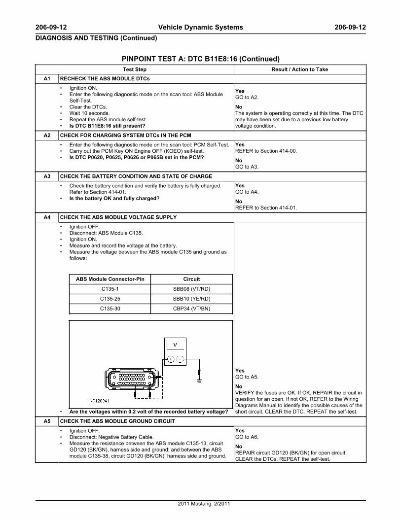
PINPOINT TEST A: DTC B11E8:16 (Continued)Test Step Result / Action to Take
A1 RECHECK THE ABS MODULE DTCs
• Ignition ON.• Enter the following diagnostic mode on the scan tool: ABS Module
Self-Test.• Clear the DTCs.• Wait 10 seconds.• Repeat the ABS module self-test.• Is DTC B11E8:16 still present?
YesGO to A2.
NoThe system is operating correctly at this time. The DTCmay have been set due to a previous low batteryvoltage condition.
A2 CHECK FOR CHARGING SYSTEM DTCs IN THE PCM
• Enter the following diagnostic mode on the scan tool: PCM Self-Test.• Carry out the PCM Key ON Engine OFF (KOEO) self-test.• Is DTC P0620, P0625, P0626 or P065B set in the PCM?
YesREFER to Section 414-00.
NoGO to A3.
A3 CHECK THE BATTERY CONDITION AND STATE OF CHARGE
• Check the battery condition and verify the battery is fully charged.Refer to Section 414-01.
• Is the battery OK and fully charged?
YesGO to A4.
NoREFER to Section 414-01.
A4 CHECK THE ABS MODULE VOLTAGE SUPPLY
• Ignition OFF.• Disconnect: ABS Module C135.• Ignition ON.• Measure and record the voltage at the battery.• Measure the voltage between the ABS module C135 and ground as
follows:
ABS Module Connector-Pin Circuit
C135-1 SBB08 (VT/RD)
C135-25 SBB10 (YE/RD)
C135-30 CBP34 (VT/BN)
• Are the voltages within 0.2 volt of the recorded battery voltage?
YesGO to A5.
NoVERIFY the fuses are OK. If OK, REPAIR the circuit inquestion for an open. If not OK, REFER to the WiringDiagrams Manual to identify the possible causes of theshort circuit. CLEAR the DTC. REPEAT the self-test.
A5 CHECK THE ABS MODULE GROUND CIRCUIT
• Ignition OFF.• Disconnect: Negative Battery Cable.• Measure the resistance between the ABS module C135-13, circuit
GD120 (BK/GN), harness side and ground; and between the ABSmodule C135-38, circuit GD120 (BK/GN), harness side and ground.
YesGO to A6.
NoREPAIR circuit GD120 (BK/GN) for open circuit.CLEAR the DTCs. REPEAT the self-test.
206-09-12 Vehicle Dynamic Systems 206-09-12DIAGNOSIS AND TESTING (Continued)
2011 Mustang, 2/2011
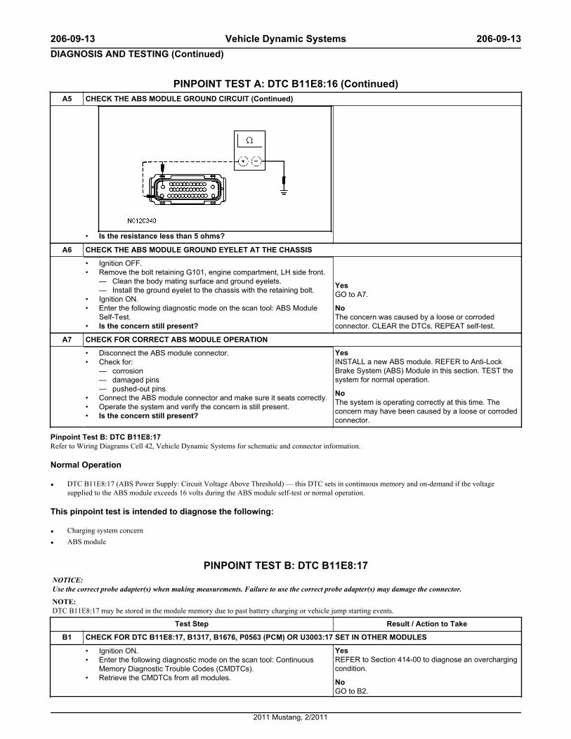
PINPOINT TEST A: DTC B11E8:16 (Continued)A5 CHECK THE ABS MODULE GROUND CIRCUIT (Continued)
• Is the resistance less than 5 ohms?
A6 CHECK THE ABS MODULE GROUND EYELET AT THE CHASSIS
• Ignition OFF.• Remove the bolt retaining G101, engine compartment, LH side front.
— Clean the body mating surface and ground eyelets.— Install the ground eyelet to the chassis with the retaining bolt.
• Ignition ON.• Enter the following diagnostic mode on the scan tool: ABS Module
Self-Test.• Is the concern still present?
YesGO to A7.
NoThe concern was caused by a loose or corrodedconnector. CLEAR the DTCs. REPEAT self-test.
A7 CHECK FOR CORRECT ABS MODULE OPERATION
• Disconnect the ABS module connector.• Check for:
— corrosion— damaged pins— pushed-out pins
• Connect the ABS module connector and make sure it seats correctly.• Operate the system and verify the concern is still present.• Is the concern still present?
YesINSTALL a new ABS module. REFER to Anti-LockBrake System (ABS) Module in this section. TEST thesystem for normal operation.
NoThe system is operating correctly at this time. Theconcern may have been caused by a loose or corrodedconnector.
Pinpoint Test B: DTC B11E8:17Refer to Wiring Diagrams Cell 42, Vehicle Dynamic Systems for schematic and connector information.
Normal Operation
• DTC B11E8:17 (ABS Power Supply: Circuit Voltage Above Threshold) — this DTC sets in continuous memory and on-demand if the voltagesupplied to the ABS module exceeds 16 volts during the ABS module self-test or normal operation.
This pinpoint test is intended to diagnose the following:
• Charging system concern
• ABS module
PINPOINT TEST B: DTC B11E8:17NOTICE: Use the correct probe adapter(s) when making measurements. Failure to use the correct probe adapter(s) may damage the connector.
NOTE: DTC B11E8:17 may be stored in the module memory due to past battery charging or vehicle jump starting events.
Test Step Result / Action to Take
B1 CHECK FOR DTC B11E8:17, B1317, B1676, P0563 (PCM) OR U3003:17 SET IN OTHER MODULES
• Ignition ON.• Enter the following diagnostic mode on the scan tool: Continuous
Memory Diagnostic Trouble Codes (CMDTCs).• Retrieve the CMDTCs from all modules.
YesREFER to Section 414-00 to diagnose an overchargingcondition.
NoGO to B2.
206-09-13 Vehicle Dynamic Systems 206-09-13DIAGNOSIS AND TESTING (Continued)
2011 Mustang, 2/2011
PINPOINT TEST B: DTC B11E8:17 (Continued)Test Step Result / Action to Take
B1 CHECK FOR DTC B11E8:17, B1317, B1676, P0563 (PCM) OR U3003:17 SET IN OTHER MODULES (Continued)• Is DTC B11E8:17, B1317, B1676, P0563 (PCM) or U3003:17 set in
more than one module?
B2 CHECK THE BATTERY VOLTAGE
• Turn off all interior/exterior lights and accessories.• Start and run the engine at approximately 2,000 rpm for 3 minutes
while monitoring the battery voltage.• Does the battery voltage rise to 15.5 volts or higher?
YesREFER to Section 414-00 to diagnose an overchargingcondition.
NoGO to B3.
B3 RECHECK FOR DTC B11E8:17
• Turn the engine off.• Ignition ON.• Enter the following diagnostic mode on the scan tool: ABS Module
Self-Test.• Clear the CMDTCs.• Carry out the ABS module self-test.• Is DTC B11E8:17 present?
YesINSTALL a new ABS module. REFER to Anti-LockBrake System (ABS) Module in this section. TEST thesystem for normal operation.
NoThe system is operating normally at this time. The DTCmay have been set previously during battery chargingor while jump starting the vehicle.
Pinpoint Test C: DTCs C0020:12, C0020:15 and C0020:71Refer to Wiring Diagrams Cell 42, Vehicle Dynamic Systems for schematic and connector information.
Normal OperationWhen the ignition key is turned to the ON position, the ABS module commands the Hydraulic Control Unit (HCU) pump on for 100 ms (±6 ms) and is thencommanded off. After 6 ms, the ABS module reads the voltage that is being generated by the HCU pump. If the voltage indicates the motor is spinning atless than 500 rpm, there may be a locked motor. If this condition is detected 4 times, DTC C0020:12 sets. The pump motor is checked for an open circuit 2seconds after the most recent successful pump motor off command. If the pump motor feedback remains greater than 0.75 volt for more than 50 ms (±6 ms)after these conditions have been met, DTC C0020:15 sets.
• DTC C0020:12 (ABS Pump Motor Control: Circuit Short To Battery) — sets in continuous memory and on-demand when the motor driver feedbackvoltage is less then battery voltage, that indicates an open driver or supply condition where the battery voltage is adjusted to the minimal threshold forthe motor supply.
• DTC C0020:15 (ABS Pump Motor Control: Circuit Short To Battery Or Open) — sets in continuous memory and on-demand if the ABS pumpfeedback voltage is greater than 0.75 volts for more than 50 ms after the pump motor has been commanded off for 2 seconds or more, if there is anopen or high resistance on the ABS pump motor circuit between the ABS module and the HCU, or if the ABS module is faulted internally.
• DTC C0020:71 (ABS Pump Motor Control: Actuator Stuck) — sets in continuous memory and on-demand if the ABS module detects that the ABSpump motor is not rotating when it is commanded to run.
This pinpoint test is intended to diagnose the following:
• Fuse
• Wiring, terminals or connectors
• HCU
• ABS module
PINPOINT TEST C: DTCs C0020:12, C0020:15 AND C0020:71NOTICE: Use the correct probe adapter(s) when making measurements. Failure to use the correct probe adapter(s) may damage the connector.
NOTE: Failure to disconnect the battery when instructed results in false resistance readings. Refer to Section 414-01.
Test Step Result / Action to Take
C1 CHECK THE PUMP MOTOR (PMP_MOTOR) ACTIVE COMMAND
• Ignition ON.• Enter the following diagnostic mode on the scan tool: ABS Module
DataLogger.• Toggle the PMP_MOTOR active command ON.• Listen for the ABS pump motor noise, does the ABS pump motor
run for approximately 2 seconds?
YesGO to C2.
NoTOGGLE the PMP_MOTOR active command OFF. GOto C3.
206-09-14 Vehicle Dynamic Systems 206-09-14DIAGNOSIS AND TESTING (Continued)
2011 Mustang, 2/2011
PINPOINT TEST C: DTCs C0020:12, C0020:15 AND C0020:71 (Continued)C2 CHECK FOR FAULT REPEATIBILITY
• Drive the vehicle at speeds greater than 20 km/h (12 mph).• Enter the following diagnostic mode on the scan tool: ABS Module
Self Test.• Are DTCs C0020:12, C0020:15 or C0020:71 retrieved?
YesGO to C3.
NoThe system is operating correctly at this time. Theconcern may have been caused by a loose or corrodedconnector.
C3 CHECK THE ABS MODULE GROUND EYELET AT THE CHASSIS
• Ignition OFF.• Remove the bolt retaining GD120, in the engine compartment, LH
side front.— Clean the body mating surface and ground eyelets.— Install the ground eyelet to the chassis with the retaining bolt.
• Ignition ON.• Enter the following diagnostic mode on the scan tool: ABS Module
Self-Test.• Are DTCs C0020:12, C0020:15, C0020:71 retrieved?
YesGO to C4.
NoThe concern was caused by a loose or corrodedconnector. CLEAR the DTCs. REPEAT self-test.
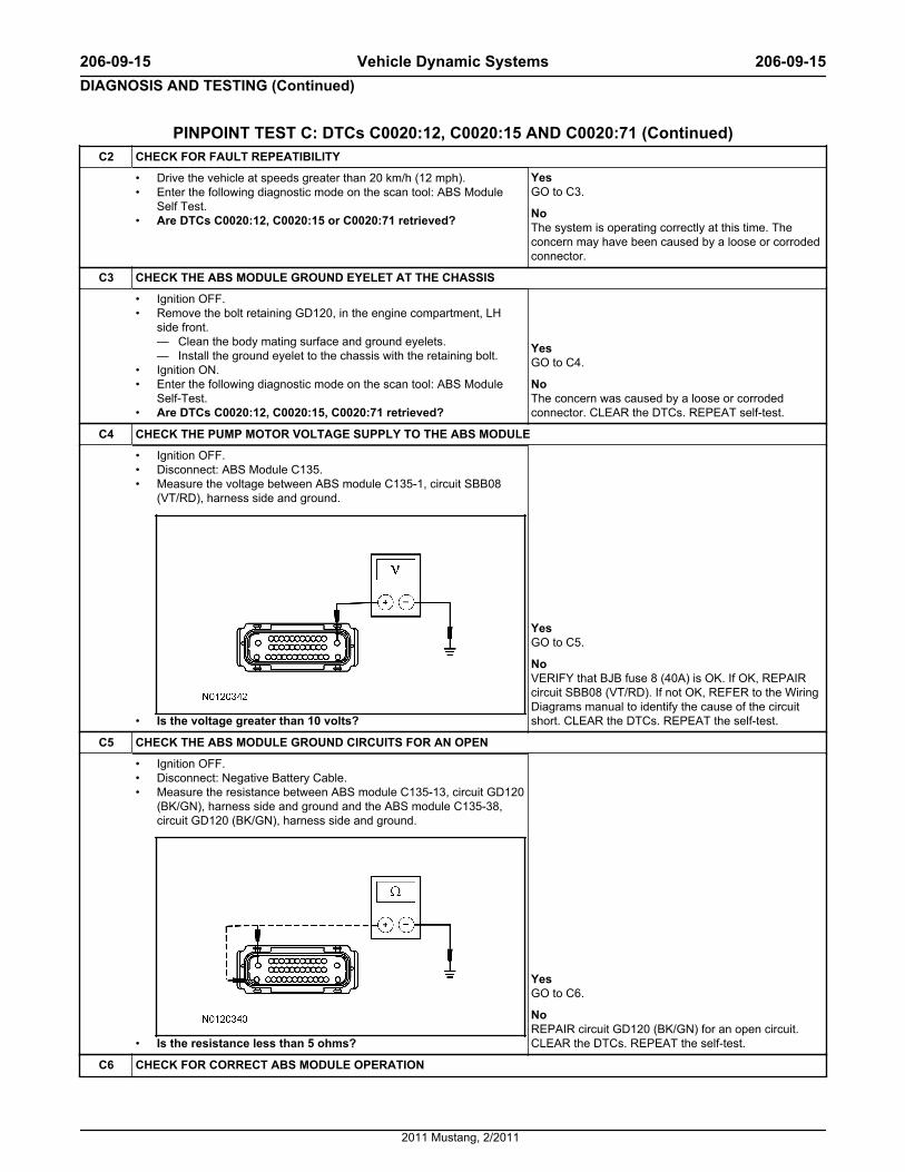
C4 CHECK THE PUMP MOTOR VOLTAGE SUPPLY TO THE ABS MODULE
• Ignition OFF.• Disconnect: ABS Module C135.• Measure the voltage between ABS module C135-1, circuit SBB08
(VT/RD), harness side and ground.
• Is the voltage greater than 10 volts?
YesGO to C5.
NoVERIFY that BJB fuse 8 (40A) is OK. If OK, REPAIRcircuit SBB08 (VT/RD). If not OK, REFER to the WiringDiagrams manual to identify the cause of the circuitshort. CLEAR the DTCs. REPEAT the self-test.
C5 CHECK THE ABS MODULE GROUND CIRCUITS FOR AN OPEN
• Ignition OFF.• Disconnect: Negative Battery Cable.• Measure the resistance between ABS module C135-13, circuit GD120
(BK/GN), harness side and ground and the ABS module C135-38,circuit GD120 (BK/GN), harness side and ground.
• Is the resistance less than 5 ohms?
YesGO to C6.
NoREPAIR circuit GD120 (BK/GN) for an open circuit.CLEAR the DTCs. REPEAT the self-test.
C6 CHECK FOR CORRECT ABS MODULE OPERATION
206-09-15 Vehicle Dynamic Systems 206-09-15DIAGNOSIS AND TESTING (Continued)
2011 Mustang, 2/2011
PINPOINT TEST C: DTCs C0020:12, C0020:15 AND C0020:71 (Continued)C6 CHECK FOR CORRECT ABS MODULE OPERATION (Continued)
• Disconnect: ABS Module.• Check for:
— corrosion— damaged pins— pushed-out pins
• Connect: ABS Module.• Make sure the connector is seated correctly, then operate the system
and verify the concern is still present.• Is the concern still present?
YesINSTALL a new ABS module. REFER to Anti-LockBrake System (ABS) Module in this section. GO to C7.
NoThe system is operating correctly at this time. Theconcern may have been caused by a loose or corrodedconnector. CLEAR the DTCs. REPEAT the self-test.
C7 CHECK FOR FAULT REPEATIBILITY
• Drive the vehicle at speeds greater than 20 km/h (12 mph).• Enter the following diagnostic mode on the scan tool: ABS Module
Self Test.• Are DTCs C0020:12, C0020:15, C0020:71 retrieved?
YesINSTALL a new HCU. REFER to Hydraulic Control Unit(HCU) in this section. TEST the system for normaloperation.
NoThe repairs are complete. The system is operatingcorrectly at this time.
Pinpoint Test D: DTCs C0031:13, C0031:17, C0031:23 (LF), C0034:13, C0034:17, C0034:23 (RF), C0037:13, C0037:17, C0037:23 (LR),C003A:13, C003A:17 and C003A:23 (RR)
Normal OperationThe wheel speed sensors are active sensors and generate a square wave signal that is sent to the ABS module. When the ignition is turned to the RUNposition, the ABS module carries out a self-test to determine if the sensors are functional. Voltage and ground are supplied to the front and rear wheel speedsensors from the ABS module along a pair of wires.
Wheel speed sensor DTCs automatically clear when a successful test drive is carried out. A successful test drive includes speeds above 32 km/h (20 mph)and at least one ABS stop.
DTC Description Fault Trigger Conditions
• C0031:13 — Left Front Wheel Speed Sensor: Circuit Open• C0034:13 — Right Front Wheel Speed Sensor: Circuit Open• C0037:13 — Left Rear Wheel Speed Sensor: Circuit Open• C003A:13 — Right Rear Wheel Speed Sensor: Circuit Open
These DTCs set in continuous memory and on-demand when the ABSmodule detects that the wheel speed sensor circuit is open or has highresistance.
• C0031:17 — Left Front Wheel Speed Sensor: Circuit Voltage AboveThreshold
• C0034:17 — Right Front Wheel Speed Sensor: Circuit Voltage AboveThreshold
• C0037:17 — Left Rear Wheel Speed Sensor: Circuit Voltage AboveThreshold
• C003A:17 — Right Rear Wheel Speed Sensor: Circuit Voltage AboveThreshold
These DTCs set in continuous memory and on-demand when the ABSmodule detects that the wheel speed sensor circuit indicates higher voltagethan expected.
• C0031:23 — Left Front Wheel Speed Sensor: Signal Stuck Low• C0034:23 — Right Front Wheel Speed Sensor: Signal Stuck Low• C0037:23 — Left Rear Wheel Speed Sensor: Signal Stuck Low• C003A:23 — Right Rear Wheel Speed Sensor: Signal Stuck Low
These DTCs set in continuous memory and on-demand when the ABSmodule detects that the wheel speed sensor circuit is shorted to ground.
This pinpoint test is intended to diagnose the following:
• Wiring, terminals or connectors
• Wheel speed sensor
• ABS module
PINPOINT TEST D: DTCs C0031:13, C0031:17, C0031:23 (LF), C0034:13, C0034:17, C0034:23(RF), C0037:13, C0037:17, C0037:23 (LR), C003A:13, C003A:17 AND C003A:23 (RR)
NOTICE: Use the correct probe adapter(s) when making measurements. Failure to use the correct probe adapter(s) may damage the connector.
Test Step Result / Action to Take
D1 CHECK FOR FAULT REPEATABILITY
206-09-16 Vehicle Dynamic Systems 206-09-16DIAGNOSIS AND TESTING (Continued)
2011 Mustang, 2/2011
PINPOINT TEST D: DTCs C0031:13, C0031:17, C0031:23 (LF), C0034:13, C0034:17, C0034:23(RF), C0037:13, C0037:17, C0037:23 (LR), C003A:13, C003A:17 AND C003A:23 (RR) (Continued)
Test Step Result / Action to Take
D1 CHECK FOR FAULT REPEATABILITY (Continued)
• Ignition ON.• Enter the following diagnostic mode on the scan tool: Clear
Continuous Memory Diagnostic Trouble Codes (CMDTCs).• Drive the vehicle at least 20 km/h (12 mph).• Enter the following diagnostic mode on the scan tool: ABS Module
Self-Test .• Is the DTC still present?
YesIf the Rotunda Active Wheel Speed Sensor Tester isavailable, GO to D2. If the Rotunda Active WheelSpeed Sensor Tester is not available, GO to D4.
NoINSPECT the wheel speed sensors and wheel speedsensor wiring. REPAIR or INSTALL new as necessary.REFER to Wheel Speed Sensor — Front or WheelSpeed Sensor — Rear in this section. If any otherDTCs are retrieved, REFER to the ABS Module DTCChart in this section.
D2 CHECK THE ABS MODULE OUTPUT USING THE ROTUNDA ACTIVE WHEEL SPEED SENSOR TESTER
• Ignition OFF.• Disconnect: Suspect Wheel Speed Sensor.• Connect the Rotunda Active Wheel Speed Sensor Tester to the wheel
speed sensor connectors.• Ignition ON.• Select the correct system polarity on the Rotunda Active Wheel
Speed Sensor Tester and turn the power switch to the ON position.• Is the module output LED illuminated?
YesGO to D3.
NoGO to D5.
D3 CHECK THE WHEEL SPEED SENSOR OUTPUT WITH THE ROTUNDA ACTIVE WHEEL SPEED SENSOR TESTER
• Raise the suspect wheel until it can spin freely. Refer to Section100-02.
• While monitoring the Rotunda Active Wheel Speed Sensor Tester,slowly spin the suspect wheel.
• Do the sensor output LEDs illuminate and flash and is thecurrent overload LED not illuminated?
YesThe system is operating correctly at this time. Theconcern may have been caused by a loose or corrodedconnector. CLEAR the DTCs. REPEAT the self-test.
NoIf the current overload LED is not illuminated and thesensor output LEDs do not illuminate or if the currentoverload LED is illuminated red, INSTALL a new wheelspeed sensor. REFER to Wheel Speed Sensor —Front or Wheel Speed Sensor — Rear in this section.CLEAR the DTCs. REPEAT the self-test.If the current overload LED is not illuminated and thesensor output LEDs illuminate green, but do not flash,INSTALL a new wheel speed sensor. REFER to WheelSpeed Sensor — Front or Wheel Speed Sensor —Rear in this section. CLEAR the DTCs. REPEAT theself-test.
D4 CHECK THE WHEEL SPEED SENSOR CIRCUITS FOR A SHORT TO BATTERY VOLTAGE
• Ignition OFF.• Disconnect: ABS Module C135.• Disconnect: Suspect Wheel Speed Sensor.• Ignition ON.• Measure the voltage between the suspect wheel speed sensor
connector, harness side and ground as follows:
Wheel Speed Sensor Circuit
LF
C150-1 VCA03 (VT/WH)
C150-2 RCA17 (YE)
RF
C160-1 VCA05 (GY/VT)
C160-2 RCA19 (VT)
YesREPAIR the affected circuit(s) for a short to voltage.CLEAR the DTCs. REPEAT the self-test.
NoGO to D5.
206-09-17 Vehicle Dynamic Systems 206-09-17DIAGNOSIS AND TESTING (Continued)
2011 Mustang, 2/2011
PINPOINT TEST D: DTCs C0031:13, C0031:17, C0031:23 (LF), C0034:13, C0034:17, C0034:23(RF), C0037:13, C0037:17, C0037:23 (LR), C003A:13, C003A:17 AND C003A:23 (RR) (Continued)
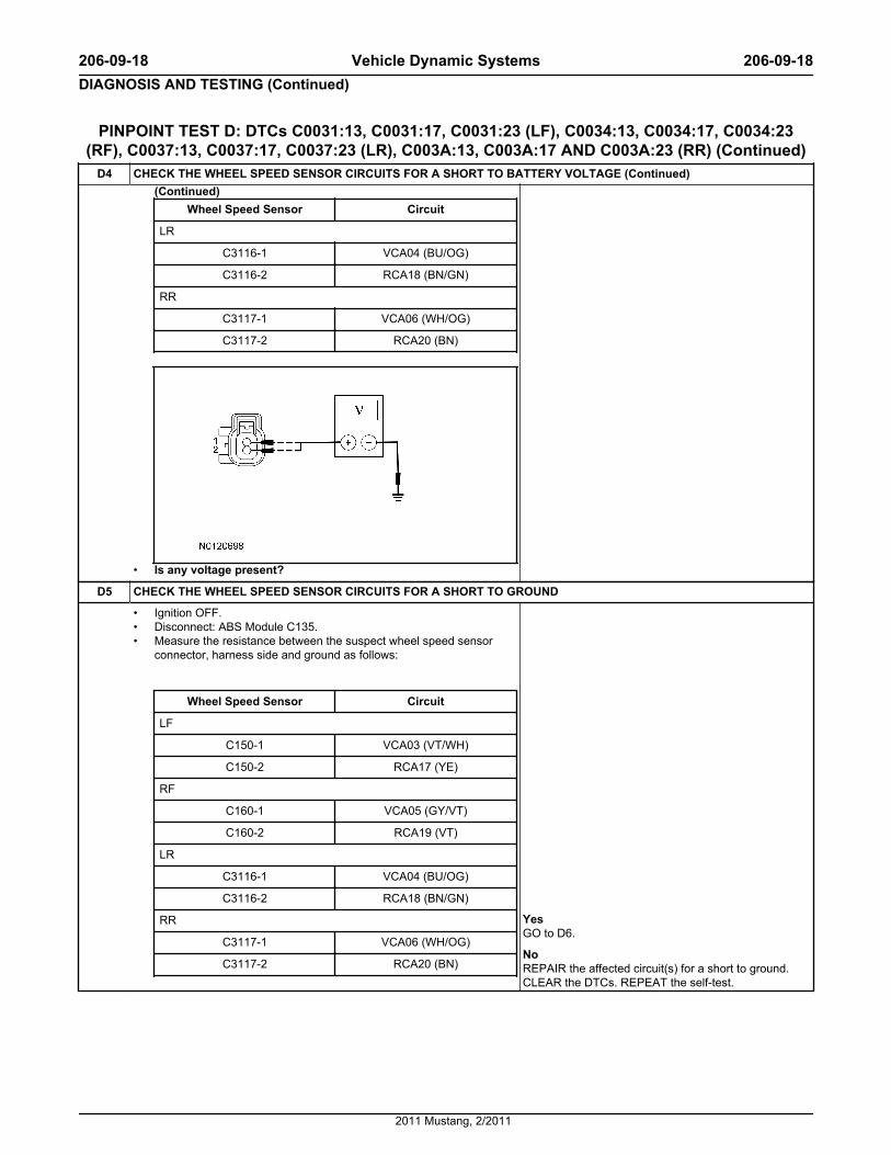
D4 CHECK THE WHEEL SPEED SENSOR CIRCUITS FOR A SHORT TO BATTERY VOLTAGE (Continued)(Continued)
Wheel Speed Sensor Circuit
LR
C3116-1 VCA04 (BU/OG)
C3116-2 RCA18 (BN/GN)
RR
C3117-1 VCA06 (WH/OG)
C3117-2 RCA20 (BN)
• Is any voltage present?
D5 CHECK THE WHEEL SPEED SENSOR CIRCUITS FOR A SHORT TO GROUND
• Ignition OFF.• Disconnect: ABS Module C135.• Measure the resistance between the suspect wheel speed sensor
connector, harness side and ground as follows:
Wheel Speed Sensor Circuit
LF
C150-1 VCA03 (VT/WH)
C150-2 RCA17 (YE)
RF
C160-1 VCA05 (GY/VT)
C160-2 RCA19 (VT)
LR
C3116-1 VCA04 (BU/OG)
C3116-2 RCA18 (BN/GN)
RR
C3117-1 VCA06 (WH/OG)
C3117-2 RCA20 (BN)
YesGO to D6.
NoREPAIR the affected circuit(s) for a short to ground.CLEAR the DTCs. REPEAT the self-test.
206-09-18 Vehicle Dynamic Systems 206-09-18DIAGNOSIS AND TESTING (Continued)
2011 Mustang, 2/2011
PINPOINT TEST D: DTCs C0031:13, C0031:17, C0031:23 (LF), C0034:13, C0034:17, C0034:23(RF), C0037:13, C0037:17, C0037:23 (LR), C003A:13, C003A:17 AND C003A:23 (RR) (Continued)
D5 CHECK THE WHEEL SPEED SENSOR CIRCUITS FOR A SHORT TO GROUND (Continued)
• Are the resistances greater than 10,000 ohms?
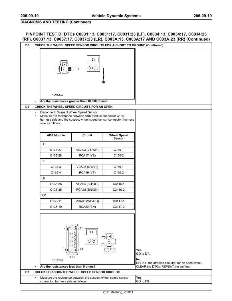
D6 CHECK THE WHEEL SPEED CIRCUITS FOR AN OPEN
• Disconnect: Suspect Wheel Speed Sensor.• Measure the resistance between ABS module connector C135,
harness side and the suspect wheel speed sensor connector, harnessside as follows:
ABS Module Circuit Wheel SpeedSensor
LF
C135-27 VCA03 (VT/WH) C150-1
C135-28 RCA17 (YE) C150-2
RF
C135-3 VCA05 (GY/VT) C160-1
C135-4 RCA19 (VT) C160-2
LR
C135-36 VCA04 (BU/OG) C3116-1
C135-35 RCA18 (BN/GN) C3116-2
RR
C135-11 VCA06 (WH/OG) C3117-1
C135-10 RCA20 (BN) C3117-2
• Are the resistances less than 5 ohms?
YesGO to D7.
NoREPAIR the affected circuit(s) for an open circuit.CLEAR the DTCs. REPEAT the self-test.
D7 CHECK FOR SHORTED WHEEL SPEED SENSOR CIRCUITS
• Measure the resistance between the suspect wheel speed sensorconnector, harness side as follows:
YesGO to D8.
206-09-19 Vehicle Dynamic Systems 206-09-19DIAGNOSIS AND TESTING (Continued)
2011 Mustang, 2/2011

PINPOINT TEST D: DTCs C0031:13, C0031:17, C0031:23 (LF), C0034:13, C0034:17, C0034:23(RF), C0037:13, C0037:17, C0037:23 (LR), C003A:13, C003A:17 AND C003A:23 (RR) (Continued)
D7 CHECK FOR SHORTED WHEEL SPEED SENSOR CIRCUITS (Continued)
Wheel Speed Sensor Circuit
LF
C150-1 VCA03 (VT/WH)
C150-2 RCA17 (YE)
RF
C160-1 VCA05 (GY/VT)
C160-2 RCA19 (VT)
LR
C3116-1 VCA04 (BU/OG)
C3116-2 RCA18 (BN/GN)
RR
C3117-1 VCA06 (WH/OG)
C3117-2 RCA20 (BN)
• Is the resistance greater than 10,000 ohms?
NoREPAIR the affected circuit(s). CLEAR the DTCs.REPEAT the self-test.
D8 CHECK FOR CORRECT ABS MODULE OUTPUT
• Ignition ON.• Measure the voltage between the suspect wheel speed sensor
connector, harness side as follows:
Wheel Speed Sensor Circuit
LF
C150-1 VCA03 (VT/WH)
C150-2 RCA17 (YE)
RF
C160-1 VCA05 (GY/VT)
C160-2 RCA19 (VT)
LR
C3116-1 VCA04 (BU/OG)
C3116-2 RCA18 (BN/GN)
RR
C3117-1 VCA06 (WH/OG)
YesREPLACE the suspect wheel speed sensor. REFER toWheel Speed Sensor — Front or Wheel Speed Sensor— Rear in this section. CLEAR the DTCs. REPEAT theself-test.
NoGO to D9.
206-09-20 Vehicle Dynamic Systems 206-09-20DIAGNOSIS AND TESTING (Continued)
2011 Mustang, 2/2011
PINPOINT TEST D: DTCs C0031:13, C0031:17, C0031:23 (LF), C0034:13, C0034:17, C0034:23(RF), C0037:13, C0037:17, C0037:23 (LR), C003A:13, C003A:17 AND C003A:23 (RR) (Continued)
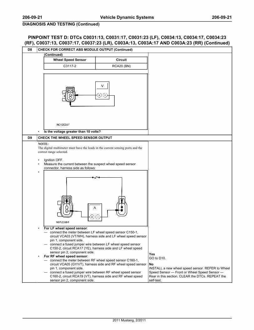
D8 CHECK FOR CORRECT ABS MODULE OUTPUT (Continued)(Continued)
Wheel Speed Sensor Circuit
C3117-2 RCA20 (BN)
• Is the voltage greater than 10 volts?
D9 CHECK THE WHEEL SPEED SENSOR OUTPUT
NOTE: The digital multimeter must have the leads in the current sensing ports and thecorrect range selected.
• Ignition OFF.• Measure the current between the suspect wheel speed sensor
connector, harness side as follows:•
• For LF wheel speed sensor:— connect the meter between LF wheel speed sensor C150-1,
circuit VCA03 (VT/WH), harness side and LF wheel speed sensorpin 1, component side.
— connect a fused jumper wire between LF wheel speed sensorC150-2, circuit RCA17 (YE), harness side and LF wheel speedsensor pin 2, component side.
• For RF wheel speed sensor:— connect the meter between RF wheel speed sensor C160-1,
circuit VCA05 (GY/VT), harness side and RF wheel speed sensorpin 1, component side.
— connect a fused jumper wire between RF wheel speed sensorC160-2, circuit RCA19 (VT), harness side and RF wheel speedsensor pin 2, component side.
YesGO to D10.
NoINSTALL a new wheel speed sensor. REFER to WheelSpeed Sensor — Front or Wheel Speed Sensor —Rear in this section. CLEAR the DTCs. REPEAT theself-test.
206-09-21 Vehicle Dynamic Systems 206-09-21DIAGNOSIS AND TESTING (Continued)
2011 Mustang, 2/2011
PINPOINT TEST D: DTCs C0031:13, C0031:17, C0031:23 (LF), C0034:13, C0034:17, C0034:23(RF), C0037:13, C0037:17, C0037:23 (LR), C003A:13, C003A:17 AND C003A:23 (RR) (Continued)
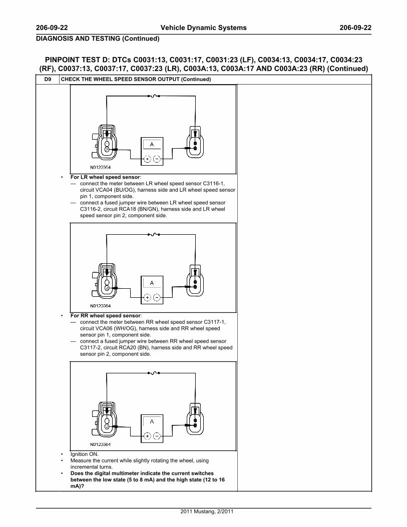
D9 CHECK THE WHEEL SPEED SENSOR OUTPUT (Continued)
• For LR wheel speed sensor:— connect the meter between LR wheel speed sensor C3116-1,
circuit VCA04 (BU/OG), harness side and LR wheel speed sensorpin 1, component side.
— connect a fused jumper wire between LR wheel speed sensorC3116-2, circuit RCA18 (BN/GN), harness side and LR wheelspeed sensor pin 2, component side.
• For RR wheel speed sensor:— connect the meter between RR wheel speed sensor C3117-1,
circuit VCA06 (WH/OG), harness side and RR wheel speedsensor pin 1, component side.
— connect a fused jumper wire between RR wheel speed sensorC3117-2, circuit RCA20 (BN), harness side and RR wheel speedsensor pin 2, component side.
• Ignition ON.• Measure the current while slightly rotating the wheel, using
incremental turns.• Does the digital multimeter indicate the current switches
between the low state (5 to 8 mA) and the high state (12 to 16mA)?
206-09-22 Vehicle Dynamic Systems 206-09-22DIAGNOSIS AND TESTING (Continued)
2011 Mustang, 2/2011

PINPOINT TEST D: DTCs C0031:13, C0031:17, C0031:23 (LF), C0034:13, C0034:17, C0034:23(RF), C0037:13, C0037:17, C0037:23 (LR), C003A:13, C003A:17 AND C003A:23 (RR) (Continued)
D10 CHECK FOR CORRECT ABS MODULE OPERATION
• Disconnect: ABS Module C135.• Check for:
— corrosion— damaged pins— pushed-out pins
• Connect: ABS Module C135.• Make sure the connector is seated correctly, then operate the system
and verify the concern is still present.• Is the concern still present?
YesINSTALL a new ABS module. REFER to Anti-LockBrake System (ABS) Module in this section. TEST thesystem for normal operation.
NoThe system is operating correctly at this time. Theconcern may have been caused by a loose or corrodedconnector. CLEAR the DTCs. REPEAT the self-test.
Pinpoint Test E: DTCs C0031:2F, C0031:62, C0034:2F, C0034:62, C0037:2F, C0037:62, C003A:2F, C003A:62 and C0078:61
Normal OperationThe wheel speed sensors are active sensors and generate a square wave signal that is sent to the ABS module. When the ignition is turned to the RUNposition, the ABS module carries out a self-test to determine if the sensors are functional. Voltage and ground are supplied to the front wheel speed sensorsfrom the ABS module along 2 circuits.
Wheel speed sensor DTCs are set in continuous memory and they automatically clear when a successful test drive is carried out. A successful test driveincludes speeds above 32 km/h (20 mph) and at least one ABS stop.
DTC Description Fault Trigger Conditions
• C0031:2F — Left Front Wheel Speed Sensor: Signal Erratic• C0034:2F — Right Front Wheel Speed Sensor: Signal Erratic• C0037:2F — Left Rear Wheel Speed Sensor: Signal Erratic• C003A:2F — Right Rear Wheel Speed Sensor: Signal Erratic
These DTCs set in continuous memory when the vehicle speed exceeds 20km/h (12 mph), and the ABS module detects an erratic wheel speed sensoracceleration. It can also be set by damaged tone rings, mismatched wheeland/or tire sizes or driving the vehicle on one or more deflated tires.
• C0031:62 — Left Front Wheel Speed Sensor: Signal Compare Failure• C0034:62 — Right Front Wheel Speed Sensor: Signal Compare
Failure• C0037:62 — Left Rear Wheel Speed Sensor: Signal Compare Failure• C003A:62 — Right Rear Wheel Speed Sensor: Signal Compare
Failure
These DTCs set in continuous memory if the ABS module detects one ofthe wheel speed sensors has a missing signal or varies by 20% of the rest ofthe wheel speed sensors. There are no wheel speed sensor shorted or opencircuit faults present in memory.
• C0078:61 — Tire Diameter: Signal Calculation Failure This DTC sets in continuous memory when the one wheel speed velocitydiffers from the rest by 25% or more. There are no wheel speed sensorfaults set in memory. It can also be set by damaged tone rings, mismatchedwheel and/or tire sizes or driving the vehicle on one or more deflated tires.
This pinpoint test is intended to diagnose the following:
• Mismatched tire sizes
• Wheel speed sensor ring
• Wheel speed sensor
• ABS module
PINPOINT TEST E: DTCs C0031:2F, C0031:62, C0034:2F, C0034:62, C0037:2F, C0037:62, C003A:2F, C003A:62 AND C0078:61
NOTICE: Use the correct probe adapter(s) when making measurements. Failure to use the correct probe adapter(s) may damage the connector.
Test Step Result / Action to Take
E1 CHECK THE DTCs FROM THE SELF-TEST
• Review the DTCs retrieved and recorded during Inspection andVerification.
• Are DTCs C0031:13; C0034:13; C0037:13 and/or C003A:13present?
YesGO to Pinpoint Test D.
NoGO to E2.
E2 CHECK THE TIRE SIZES AND PRESSURE
• Verify that all tires and wheels are the same size and that the tire sizeand inflation pressures are correct as indicated on the VehicleCertification (VC) label.
YesGO to E3.
206-09-23 Vehicle Dynamic Systems 206-09-23DIAGNOSIS AND TESTING (Continued)
2011 Mustang, 2/2011
PINPOINT TEST E: DTCs C0031:2F, C0031:62, C0034:2F, C0034:62, C0037:2F, C0037:62, C003A:2F, C003A:62 AND C0078:61 (Continued)
E2 CHECK THE TIRE SIZES AND PRESSURE (Continued)• Are the wheels and tires OK? No
INSTALL the correct size tire/wheel or ADJUST tirepressure as necessary. CLEAR the DTCs. REPEATthe self-test.
E3 MONITOR THE WHEEL SPEED SENSOR PIDs
• Ignition ON.• Enter the following diagnostic mode on the scan tool: ABS Module
DataLogger.• Drive the vehicle at a speed greater than 20 km/h (12 mph) while
monitoring the following PIDs:— Left front wheel speed sensor (LF_WSPD)— Right front wheel speed sensor (RF_WSPD)— Left rear wheel speed sensor (LR_WSPD)— Right rear wheel speed sensor (RR_WSPD)
• Are the wheel speed PIDs consistent (within [5 km/h (3 mph])with each other and the vehicle speed as indicated on thespeedometer?
YesGO to E11.
NoGO to E4.
E4 CHECK THE WHEEL SPEED SENSOR FOR DAMAGE
• NOTE: Examine the wheel speed sensor wire carefully with a good lightsource. Failure to verify damage in the wheel speed sensor wire canlead to unnecessary installation of a new component.
Inspect the wheel speed sensor and harness for abrasion, brokenconnector tabs or water intrusion.
• Is the wheel speed sensor and harness OK?
YesGO to E5.
NoINSTALL a new wheel speed sensor. REFER to WheelSpeed Sensor — Front or Wheel Speed Sensor —Rear in this section. CLEAR the DTCs. REPEAT theself-test.
E5 INSPECT THE WHEEL SPEED SENSOR MOUNTING
• Ignition OFF.• With the vehicle in NEUTRAL, position it on a hoist. Refer to Section
100-02.• Inspect the wheel speed sensor and fastener for looseness.• Are the wheel speed sensor and fastener tight?
YesGO to E6.
NoTIGHTEN the wheel speed sensor to specification.REFER to Specifications in this section. CLEAR theDTCs. REPEAT the self-test.
E6 CHECK TONE RING FOR DAMAGE
• Inspect the tone rings for abnormal wear or roughness and fordamage.
• Are the tone ring(s) OK?
YesFor wheel speed sensor testing with the RotundaActive Wheel Speed Sensor Tester, GO to E7.For wheel speed sensor testing without the RotundaActive Wheel Speed Sensor Tester, GO to E9.
NoINSTALL a new tone ring as necessary. REFER toWheel Speed Sensor Ring — Front or Wheel SpeedSensor Ring — Rear in this section. CLEAR the DTCs.REPEAT the self-test.
E7 CHECK THE ABS MODULE OUTPUT USING THE ROTUNDA ACTIVE WHEEL SPEED SENSOR TESTER
• Disconnect: Suspect Wheel Speed Sensor.• Connect the Rotunda Active Wheel Speed Sensor Tester to the wheel
speed sensor connectors.• Ignition ON.• Select the correct system polarity on the Rotunda Active Wheel
Speed Sensor Tester and turn the power switch to the ON position.• Is the module output LED illuminated?
YesGO to E8.
NoGO to E11.
E8 CHECK THE WHEEL SPEED SENSOR OUTPUT WITH THE ROTUNDA ACTIVE WHEEL SPEED SENSOR TESTER
• Raise the suspect wheel until it can spin freely. Refer to Section100-02.
• While monitoring the Rotunda Active Wheel Speed Sensor Tester,slowly spin the suspect wheel.
YesThe system is operating correctly at this time. Theconcern may have been caused by a loose or corrodedconnector. CLEAR the DTCs. REPEAT the self-test.
206-09-24 Vehicle Dynamic Systems 206-09-24DIAGNOSIS AND TESTING (Continued)
2011 Mustang, 2/2011
PINPOINT TEST E: DTCs C0031:2F, C0031:62, C0034:2F, C0034:62, C0037:2F, C0037:62, C003A:2F, C003A:62 AND C0078:61 (Continued)
E8 CHECK THE WHEEL SPEED SENSOR OUTPUT WITH THE ROTUNDA ACTIVE WHEEL SPEED SENSOR TESTER(Continued)• Do the sensor output LEDs illuminate and flash and is the
current overload LED not illuminated?NoIf the current overload LED is not illuminated and thesensor output LEDs do not illuminate or if the currentlevel LED is illuminated red, INSTALL a new wheelspeed sensor. REFER to Wheel Speed Sensor —Front or Wheel Speed Sensor — Rear in this section.CLEAR the DTCs. REPEAT the self-test.If the current overload LED is not illuminated and thesensor output LEDs illuminate green, but do not flash,INSTALL a new wheel speed sensor. REFER to WheelSpeed Sensor — Front or Wheel Speed Sensor —Rear in this section. CLEAR the DTCs. REPEAT theself-test.If the sensor output LEDs still illuminate but do notflash REPLACE the suspect tone ring(s). REFER toWheel Speed Sensor Ring — Front or Wheel SpeedSensor Ring — Rear in this section.
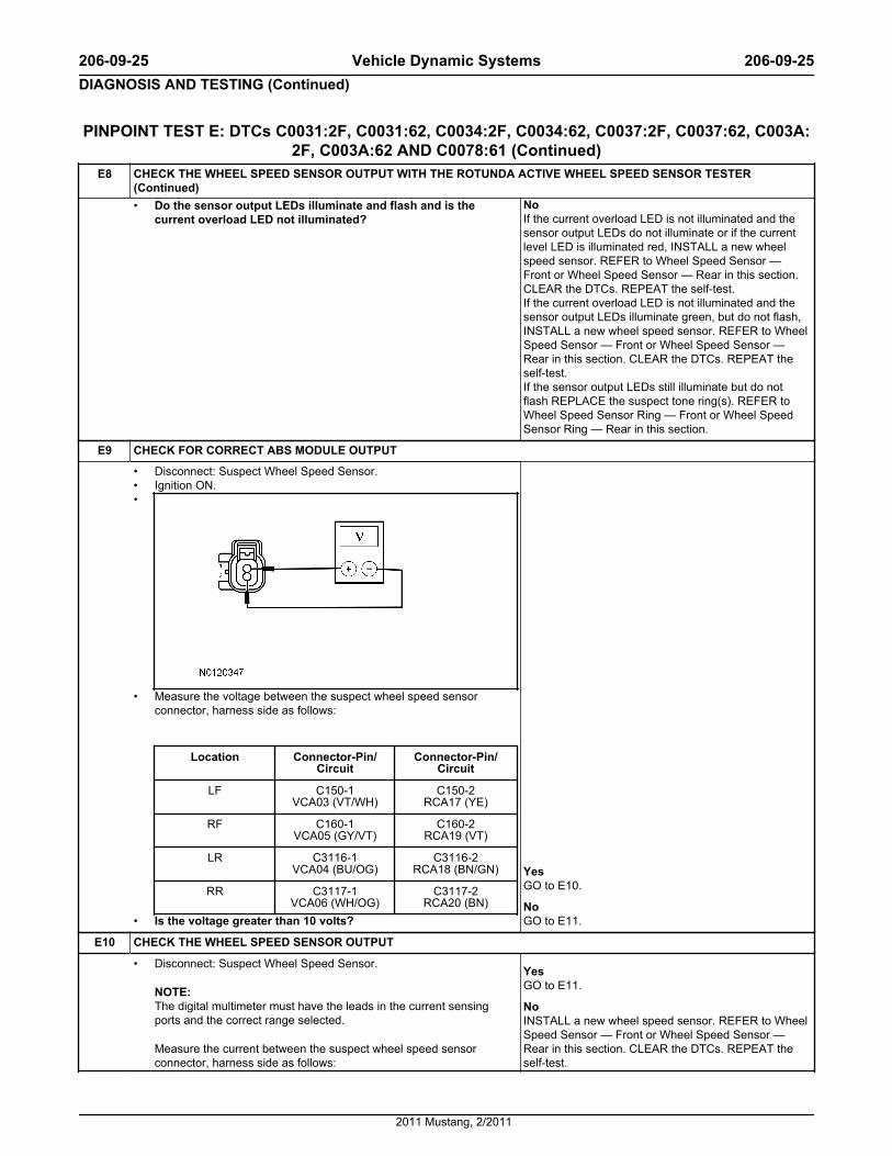
E9 CHECK FOR CORRECT ABS MODULE OUTPUT
• Disconnect: Suspect Wheel Speed Sensor.• Ignition ON.•
• Measure the voltage between the suspect wheel speed sensorconnector, harness side as follows:
Location Connector-Pin/Circuit
Connector-Pin/Circuit
LF C150-1VCA03 (VT/WH)
C150-2RCA17 (YE)
RF C160-1VCA05 (GY/VT)
C160-2RCA19 (VT)
LR C3116-1VCA04 (BU/OG)
C3116-2RCA18 (BN/GN)
RR C3117-1VCA06 (WH/OG)
C3117-2RCA20 (BN)
• Is the voltage greater than 10 volts?
YesGO to E10.
NoGO to E11.
E10 CHECK THE WHEEL SPEED SENSOR OUTPUT
• Disconnect: Suspect Wheel Speed Sensor.
NOTE: The digital multimeter must have the leads in the current sensingports and the correct range selected.
Measure the current between the suspect wheel speed sensorconnector, harness side as follows:
YesGO to E11.
NoINSTALL a new wheel speed sensor. REFER to WheelSpeed Sensor — Front or Wheel Speed Sensor —Rear in this section. CLEAR the DTCs. REPEAT theself-test.
206-09-25 Vehicle Dynamic Systems 206-09-25DIAGNOSIS AND TESTING (Continued)
2011 Mustang, 2/2011

PINPOINT TEST E: DTCs C0031:2F, C0031:62, C0034:2F, C0034:62, C0037:2F, C0037:62, C003A:2F, C003A:62 AND C0078:61 (Continued)
E10 CHECK THE WHEEL SPEED SENSOR OUTPUT (Continued)•
• For the LF wheel speed sensor:— connect the meter between LF wheel speed sensor C150-1,
circuit VCA03 (VT/WH), harness side and LF wheel speed sensorpin 1, component side.
— connect a fused jumper wire between LF wheel speed sensorC150-2, circuit RCA17 (YE), harness side and LF wheel speedsensor pin 2, component side.
• For the RF wheel speed sensor:— connect the meter between RF wheel speed sensor C160-1,
circuit VCA05 (GY/VT), harness side and RF wheel speed sensorpin 1, component side.
— connect a fused jumper wire between RF wheel speed sensorC160-2, circuit RCA19 (VT), harness side and RF wheel speedsensor pin 2, component side.
• For the LR wheel speed sensor:— connect the meter between LR wheel speed sensor C3116-1,
circuit VCA04 (BU/OG), harness side and LR wheel speed sensorpin 1, component side.
— connect a fused jumper wire between LR wheel speed sensorC3116-2, circuit RCA18 (BN/GN), harness side and LR wheelspeed sensor pin 2, component side.
206-09-26 Vehicle Dynamic Systems 206-09-26DIAGNOSIS AND TESTING (Continued)
2011 Mustang, 2/2011
PINPOINT TEST E: DTCs C0031:2F, C0031:62, C0034:2F, C0034:62, C0037:2F, C0037:62, C003A:2F, C003A:62 AND C0078:61 (Continued)
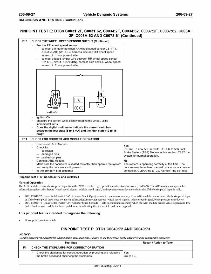
E10 CHECK THE WHEEL SPEED SENSOR OUTPUT (Continued)• For the RR wheel speed sensor:
— connect the meter between RR wheel speed sensor C3117-1,circuit VCA06 (WH/OG), harness side and RR wheel speedsensor pin 1, component side.
— connect a fused jumper wire between RR wheel speed sensorC3117-2, circuit RCA20 (BN), harness side and RR wheel speedsensor pin 2, component side.
• Ignition ON.• Measure the current while slightly rotating the wheel, using
incremental turns.• Does the digital multimeter indicate the current switches
between the low state (5 to 8 mA) and the high state (12 to 16mA)?
E11 CHECK FOR CORRECT ABS MODULE OPERATION
• Disconnect: ABS Module .• Check for:
— corrosion— damaged pins— pushed-out pins
• Connect: ABS Module .• Make sure the connector is seated correctly, then operate the system
and verify the concern is still present.• Is the concern still present?
YesINSTALL a new ABS module. REFER to Anti-LockBrake System (ABS) Module in this section. TEST thesystem for normal operation.
NoThe system is operating correctly at this time. Theconcern may have been caused by a loose or corrodedconnector. CLEAR the DTCs. REPEAT the self-test.
Pinpoint Test F: DTCs C0040:72 and C0040:73
Normal OperationThe ABS module receives brake pedal input from the PCM over the High Speed Controller Area Network (HS-CAN). The ABS module compares thisinformation against other inputs (wheel speed signals, vehicle speed signal, brake pressure transducer) to determine if the brake pedal input is valid.
• DTC C0040:72 (Brake Pedal Switch "A": Actuator Stuck Open) — sets in continuous memory if the ABS module cannot detect the brake pedal inputor if the brake pedal input does not match information from other sensors (wheel speed signals, vehicle speed signal, brake pressure transducer).
• DTC C0040:73 (Brake Pedal Switch "A": Actuator Stuck Closed) — sets in continuous memory when the ABS module senses vehicle speed and lowbrake fluid pressure, while the brake pedal input is indicating that the vehicle brakes are applied.
This pinpoint test is intended to diagnose the following:
• Brake pedal position switch
PINPOINT TEST F: DTCs C0040:72 AND C0040:73NOTICE: Use the correct probe adapter(s) when making measurements. Failure to use the correct probe adapter(s) may damage the connector.
Test Step Result / Action to Take
F1 CHECK THE STOPLAMPS FOR CORRECT OPERATION
• Check the stoplamps for correct operation by pressing and releasingthe brake pedal and observing the stoplamps.
YesGO to F2.
206-09-27 Vehicle Dynamic Systems 206-09-27DIAGNOSIS AND TESTING (Continued)
2011 Mustang, 2/2011
PINPOINT TEST F: DTCs C0040:72 AND C0040:73 (Continued)Test Step Result / Action to Take
F1 CHECK THE STOPLAMPS FOR CORRECT OPERATION (Continued)• Do the stoplamps operate correctly? No
REFER to Section 417-01.
F2 CHECK THE ABS MODULE DTCs
• Review the ABS module DTCs retrieved during Inspection andVerification.
• Is DTC U0100:00 present?
YesGO to Pinpoint Test I.
NoFor DTC C0040:72 GO to F3.For DTC C0040:73, INSTALL a new stoplamp switch.REFER to Section 417-01. CLEAR the DTCs. REPEATthe self-test.
F3 CHECK THE ABS MODULE BRAKE PRESSURE PID
• Enter the following diagnostic mode on the scan tool: ABS ModuleDataLogger.
• Monitor the BPS_EE12 PID with the brake pedal released.• Does the BPS_EE12 PID show brake pressure lower than 132
psi?
YesThe system is operating correctly at this time. CLEARthe DTCs. REPEAT the self-test.
NoGO to F4.
F4 CHECK THE ABS MODULE BRAKE PRESSURE PID
• Disconnect: Cruise Control Deactivator Switch C277.• Remove the cruise control deactivator switch. Refer to Section
419-03.• Enter the following diagnostic mode on the scan tool: ABS Module
DataLogger.• Monitor the BPS_EE12 PID with the brake pedal released.• Does the BPS_EE12 PID show brake pressure lower than 132
psi?
YesINSTALL a new cruise control deactivator switch.REFER to Section 419-03. CLEAR the DTCs. REPEATthe self-test.
NoGO to F5.
F5 CHECK THE ABS MODULE BRAKE PRESSURE PID
• Connect: Cruise Control Deactivator Switch C277.• Enter the following diagnostic mode on the scan tool: ABS Module
DataLogger.• Connect: Stoplamp Switch C278.• Remove the stoplamp switch.• Monitor the BPS_EE12 PID with the brake pedal released.• Does the BPS_EE12 PID show brake pressure lower than 132
psi?
YesINSTALL a new stoplamp switch. REFER to Section417-01. CLEAR the DTCs. REPEAT the self-test.
NoGO to F6.
F6 CHECK FOR CORRECT ABS MODULE OPERATION
• Disconnect: ABS Module .• Check for:
— corrosion— damaged pins— pushed-out pins
• Connect: ABS Module .• Make sure the connector is seated correctly, then operate the system
and verify the concern is still present.• Is the concern still present?
YesINSTALL a new ABS module. REFER to Anti-LockBrake System (ABS) Module in this section. TEST thesystem for normal operation.
NoThe system is operating correctly at this time. Theconcern may have been caused by a loose or corrodedconnector. CLEAR the DTCs. REPEAT the self-test.
Pinpoint Test G: DTC C1A98:54Refer to Wiring Diagrams Cell 42, Vehicle Dynamic Systems for schematic and connector information.
Normal OperationThe ABS module needs to be calibrated whenever a component specific to the Electronic Stability Control (ESC) system is disconnected or a newcomponent is installed. Calibration allows the ABS module to identify the zero position of the sensors so the system can operate correctly.
• DTC C1A98:54 (Yaw Rate Sensor: Missing Calibration) — sets in continuous memory if the initialization sequence does not finish or if the ABSmodule loses the stability sensor calibration information.
This pinpoint test is intended to diagnose the following:
• ABS module calibration
206-09-28 Vehicle Dynamic Systems 206-09-28DIAGNOSIS AND TESTING (Continued)
2011 Mustang, 2/2011

PINPOINT TEST G: DTC C1A98:54NOTE: The stability/traction control indicator (sliding car icon) flashes when a system calibration is required. Calibration is required after the ABS module or theRestraints Control Module (RCM) is replaced.
NOTE: The vehicle must be on level ground, at a complete standstill, in NEUTRAL with the brakes applied, and not on a hoist while carrying out the calibrationprocedure. Any vehicle movement results in calibration failure.
Test Step Result / Action to Take
G1 CHECK FOR ABS MODULE DTCs
• Ignition ON.• Enter the following diagnostic mode on the scan tool: ABS Module
Self-Test.• Retrieve and record any ABS module DTCs.• Is any other DTC retrieved with C1A98:54 ?
YesDIAGNOSE all other DTCs first. REFER to the ABSModule DTC Chart in this section.
NoGO to G2.
G2 CALIBRATE THE ABS MODULE
• Using the scan tool, carry out the IVD Initialization sequence. Followthe scan tool instructions.
• Does the IVD Initialization sequence complete for all of thestability sensors and does the stability/traction control indicator(sliding car icon) stop flashing and turn off?
YesGO to G3.
NoGO to G4.
G3 CHECK FOR RETURNING DTCs
• Using the scan tool, clear the ABS module DTCs.• Ignition OFF.• Ignition ON.• Enter the following diagnostic mode on the scan tool: ABS Module
Self Test.• Retrieve and record any ABS module DTCs.• Does the DTC C1A98:54 clear and not return?
YesThe calibration is complete. The concern may havebeen caused by an incorrect or incomplete calibration.
NoGO to G4.
G4 CHECK FOR CORRECT ABS MODULE OPERATION
• Disconnect: ABS Module .• Check ABS Module connector
— corrosion— damaged pins— pushed-out pins
• Connect: ABS Module .• Make sure the connector seats correctly, then operate the system and
verify the concern is still present.• Is the concern still present?
YesINSTALL a new ABS module. REFER to Anti-LockBrake System (ABS) Module in this section. CLEARthe DTCs. REPEAT the self-test.
NoThe system is operating correctly at this time. Theconcern may have been caused by a loose or corrodedconnector. CLEAR the DTCs. CARRY OUT the self-test with the brake pedal not applied.
Pinpoint Test H: DTCs C1A99:14, C1A99:17, C1A99:2F, C1A99:62, C1A99:65 and C1A99:67
Normal OperationThe ABS module uses internal pressure sensors to determine correct operation by monitoring internal Hydraulic Control Unit (HCU) hydraulic pressures.These DTCs set if the brake pressure sensor signals do not match. This fault could set by either an internal ABS module failure or an HCU pressure sensorfailure. The pressure sensors are internal to the HCU and cannot be serviced separately.
DTC Description Fault Trigger Conditions
• C1A99:14 — Pressure Sensor: Circuit Short To Ground Or Open Sets in continuous memory if the brake pressure sensor signal is lower thanexpected.
• C1A99:17 — Pressure Sensor: Circuit Voltage Above Threshold Sets in continuous memory if the brake pressure sensor signal is higher thanexpected.
• C1A99:2F — Pressure Sensor: Signal Erratic Sets in continuous memory if the brake pressure sensor signal is erratic orfluctuating abnormally. This fault could set by either an internal ABSmodule failure or a pressure sensor failure.
• C1A99:62 — Pressure Sensor: Signal Compare Failure Sets in continuous memory if the brake pressure sensor signal fails theinternal accuracy check.
• C1A99:65 — Pressure Sensor: Signal Has Too Few Transitions/Events
Sets in continuous memory if the brake pressure sensor signals are notactive.
206-09-29 Vehicle Dynamic Systems 206-09-29DIAGNOSIS AND TESTING (Continued)
2011 Mustang, 2/2011
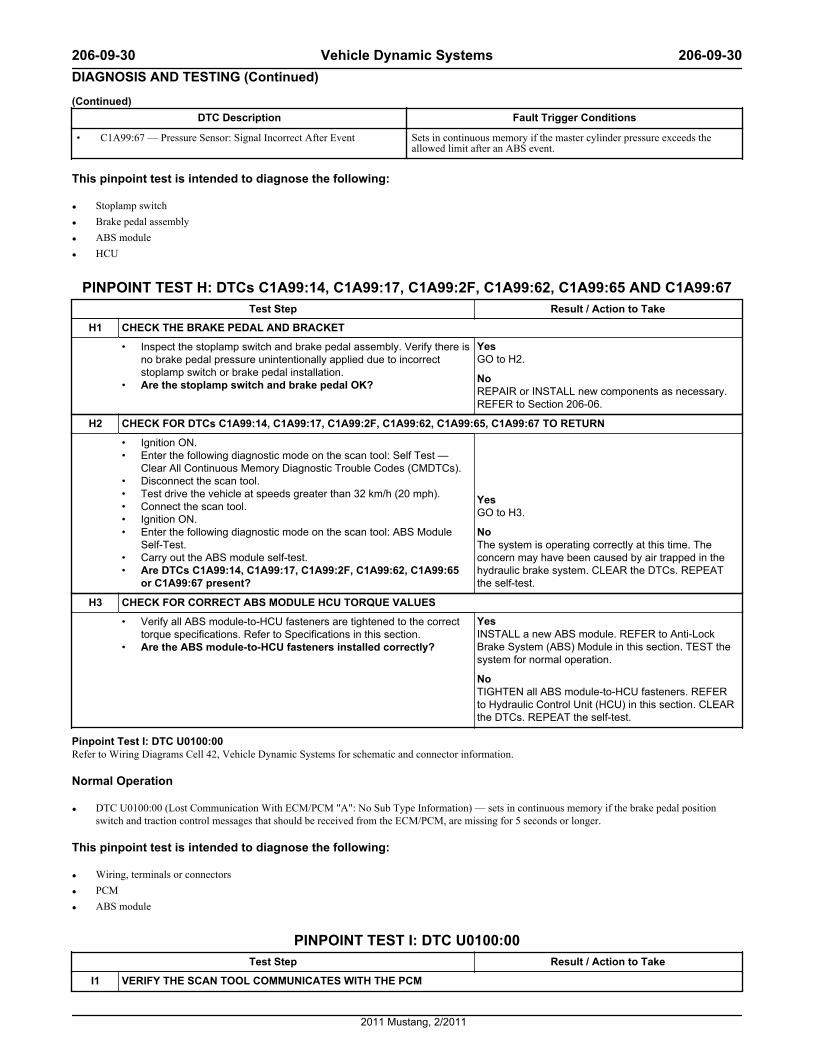
(Continued)DTC Description Fault Trigger Conditions
• C1A99:67 — Pressure Sensor: Signal Incorrect After Event Sets in continuous memory if the master cylinder pressure exceeds theallowed limit after an ABS event.
This pinpoint test is intended to diagnose the following:
• Stoplamp switch
• Brake pedal assembly
• ABS module
• HCU
PINPOINT TEST H: DTCs C1A99:14, C1A99:17, C1A99:2F, C1A99:62, C1A99:65 AND C1A99:67Test Step Result / Action to Take
H1 CHECK THE BRAKE PEDAL AND BRACKET
• Inspect the stoplamp switch and brake pedal assembly. Verify there isno brake pedal pressure unintentionally applied due to incorrectstoplamp switch or brake pedal installation.
• Are the stoplamp switch and brake pedal OK?
YesGO to H2.
NoREPAIR or INSTALL new components as necessary.REFER to Section 206-06.
H2 CHECK FOR DTCs C1A99:14, C1A99:17, C1A99:2F, C1A99:62, C1A99:65, C1A99:67 TO RETURN
• Ignition ON.• Enter the following diagnostic mode on the scan tool: Self Test —
Clear All Continuous Memory Diagnostic Trouble Codes (CMDTCs).• Disconnect the scan tool.• Test drive the vehicle at speeds greater than 32 km/h (20 mph).• Connect the scan tool.• Ignition ON.• Enter the following diagnostic mode on the scan tool: ABS Module
Self-Test.• Carry out the ABS module self-test.• Are DTCs C1A99:14, C1A99:17, C1A99:2F, C1A99:62, C1A99:65
or C1A99:67 present?
YesGO to H3.
NoThe system is operating correctly at this time. Theconcern may have been caused by air trapped in thehydraulic brake system. CLEAR the DTCs. REPEATthe self-test.
H3 CHECK FOR CORRECT ABS MODULE HCU TORQUE VALUES
• Verify all ABS module-to-HCU fasteners are tightened to the correcttorque specifications. Refer to Specifications in this section.
• Are the ABS module-to-HCU fasteners installed correctly?
YesINSTALL a new ABS module. REFER to Anti-LockBrake System (ABS) Module in this section. TEST thesystem for normal operation.
NoTIGHTEN all ABS module-to-HCU fasteners. REFERto Hydraulic Control Unit (HCU) in this section. CLEARthe DTCs. REPEAT the self-test.
Pinpoint Test I: DTC U0100:00Refer to Wiring Diagrams Cell 42, Vehicle Dynamic Systems for schematic and connector information.
Normal Operation
• DTC U0100:00 (Lost Communication With ECM/PCM "A": No Sub Type Information) — sets in continuous memory if the brake pedal positionswitch and traction control messages that should be received from the ECM/PCM, are missing for 5 seconds or longer.
This pinpoint test is intended to diagnose the following:
• Wiring, terminals or connectors
• PCM
• ABS module
PINPOINT TEST I: DTC U0100:00Test Step Result / Action to Take
I1 VERIFY THE SCAN TOOL COMMUNICATES WITH THE PCM
206-09-30 Vehicle Dynamic Systems 206-09-30DIAGNOSIS AND TESTING (Continued)
2011 Mustang, 2/2011
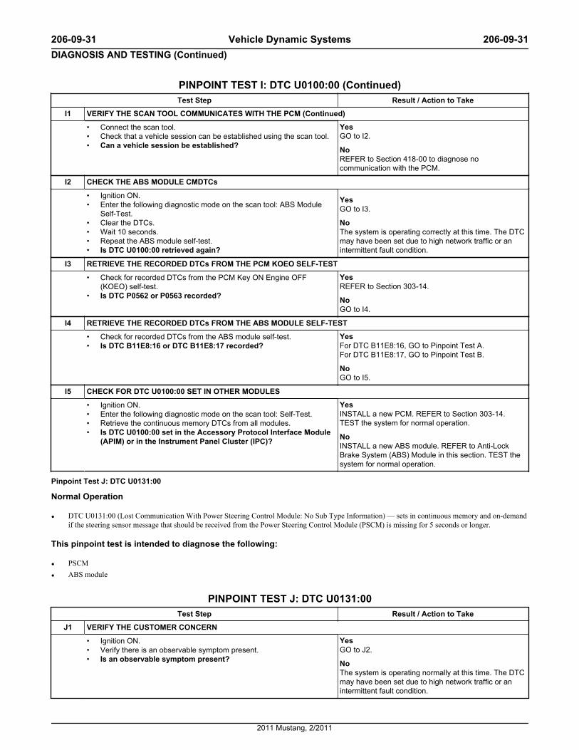
PINPOINT TEST I: DTC U0100:00 (Continued)Test Step Result / Action to Take
I1 VERIFY THE SCAN TOOL COMMUNICATES WITH THE PCM (Continued)
• Connect the scan tool.• Check that a vehicle session can be established using the scan tool.• Can a vehicle session be established?
YesGO to I2.
NoREFER to Section 418-00 to diagnose nocommunication with the PCM.
I2 CHECK THE ABS MODULE CMDTCs
• Ignition ON.• Enter the following diagnostic mode on the scan tool: ABS Module
Self-Test.• Clear the DTCs.• Wait 10 seconds.• Repeat the ABS module self-test.• Is DTC U0100:00 retrieved again?
YesGO to I3.
NoThe system is operating correctly at this time. The DTCmay have been set due to high network traffic or anintermittent fault condition.
I3 RETRIEVE THE RECORDED DTCs FROM THE PCM KOEO SELF-TEST
• Check for recorded DTCs from the PCM Key ON Engine OFF(KOEO) self-test.
• Is DTC P0562 or P0563 recorded?
YesREFER to Section 303-14.
NoGO to I4.
I4 RETRIEVE THE RECORDED DTCs FROM THE ABS MODULE SELF-TEST
• Check for recorded DTCs from the ABS module self-test.• Is DTC B11E8:16 or DTC B11E8:17 recorded?
YesFor DTC B11E8:16, GO to Pinpoint Test A.For DTC B11E8:17, GO to Pinpoint Test B.
NoGO to I5.
I5 CHECK FOR DTC U0100:00 SET IN OTHER MODULES
• Ignition ON.• Enter the following diagnostic mode on the scan tool: Self-Test.• Retrieve the continuous memory DTCs from all modules.• Is DTC U0100:00 set in the Accessory Protocol Interface Module
(APIM) or in the Instrument Panel Cluster (IPC)?
YesINSTALL a new PCM. REFER to Section 303-14.TEST the system for normal operation.
NoINSTALL a new ABS module. REFER to Anti-LockBrake System (ABS) Module in this section. TEST thesystem for normal operation.
Pinpoint Test J: DTC U0131:00
Normal Operation
• DTC U0131:00 (Lost Communication With Power Steering Control Module: No Sub Type Information) — sets in continuous memory and on-demandif the steering sensor message that should be received from the Power Steering Control Module (PSCM) is missing for 5 seconds or longer.
This pinpoint test is intended to diagnose the following:
• PSCM
• ABS module
PINPOINT TEST J: DTC U0131:00Test Step Result / Action to Take
J1 VERIFY THE CUSTOMER CONCERN
• Ignition ON.• Verify there is an observable symptom present.• Is an observable symptom present?
YesGO to J2.
NoThe system is operating normally at this time. The DTCmay have been set due to high network traffic or anintermittent fault condition.
206-09-31 Vehicle Dynamic Systems 206-09-31DIAGNOSIS AND TESTING (Continued)
2011 Mustang, 2/2011
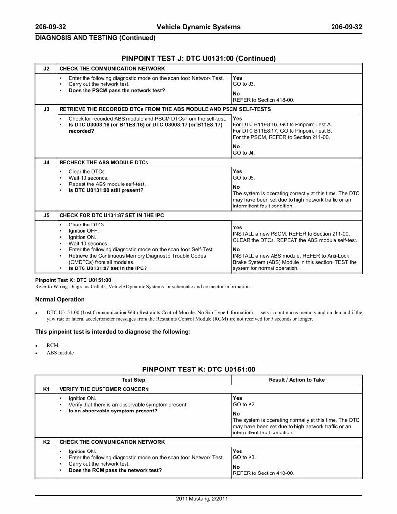
PINPOINT TEST J: DTC U0131:00 (Continued)J2 CHECK THE COMMUNICATION NETWORK
• Enter the following diagnostic mode on the scan tool: Network Test.• Carry out the network test.• Does the PSCM pass the network test?
YesGO to J3.
NoREFER to Section 418-00.
J3 RETRIEVE THE RECORDED DTCs FROM THE ABS MODULE AND PSCM SELF-TESTS
• Check for recorded ABS module and PSCM DTCs from the self-test.• Is DTC U3003:16 (or B11E8:16) or DTC U3003:17 (or B11E8:17)
recorded?
YesFor DTC B11E8:16, GO to Pinpoint Test A.For DTC B11E8:17, GO to Pinpoint Test B.For the PSCM, REFER to Section 211-00.
NoGO to J4.
J4 RECHECK THE ABS MODULE DTCs
• Clear the DTCs.• Wait 10 seconds.• Repeat the ABS module self-test.• Is DTC U0131:00 still present?
YesGO to J5.
NoThe system is operating correctly at this time. The DTCmay have been set due to high network traffic or anintermittent fault condition.
J5 CHECK FOR DTC U131:87 SET IN THE IPC
• Clear the DTCs.• Ignition OFF.• Ignition ON.• Wait 10 seconds.• Enter the following diagnostic mode on the scan tool: Self-Test.• Retrieve the Continuous Memory Diagnostic Trouble Codes
(CMDTCs) from all modules.• Is DTC U0131:87 set in the IPC?
YesINSTALL a new PSCM. REFER to Section 211-00.CLEAR the DTCs. REPEAT the ABS module self-test.
NoINSTALL a new ABS module. REFER to Anti-LockBrake System (ABS) Module in this section. TEST thesystem for normal operation.
Pinpoint Test K: DTC U0151:00Refer to Wiring Diagrams Cell 42, Vehicle Dynamic Systems for schematic and connector information.
Normal Operation
• DTC U0151:00 (Lost Communication With Restraints Control Module: No Sub Type Information) — sets in continuous memory and on-demand if theyaw rate or lateral accelerometer messages from the Restraints Control Module (RCM) are not received for 5 seconds or longer.
This pinpoint test is intended to diagnose the following:
• RCM
• ABS module
PINPOINT TEST K: DTC U0151:00Test Step Result / Action to Take
K1 VERIFY THE CUSTOMER CONCERN
• Ignition ON.• Verify that there is an observable symptom present.• Is an observable symptom present?
YesGO to K2.
NoThe system is operating normally at this time. The DTCmay have been set due to high network traffic or anintermittent fault condition.
K2 CHECK THE COMMUNICATION NETWORK
• Ignition ON.• Enter the following diagnostic mode on the scan tool: Network Test.• Carry out the network test.• Does the RCM pass the network test?
YesGO to K3.
NoREFER to Section 418-00.
206-09-32 Vehicle Dynamic Systems 206-09-32DIAGNOSIS AND TESTING (Continued)
2011 Mustang, 2/2011
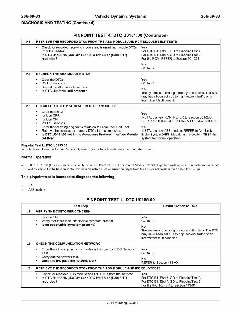
PINPOINT TEST K: DTC U0151:00 (Continued)K3 RETRIEVE THE RECORDED DTCs FROM THE ABS MODULE AND RCM MODULE SELF-TESTS
• Check for recorded receiving module and transmitting module DTCsfrom the self-test.
• Is DTC B11E8:16 (U3003:16) or DTC B11E8:17 (U3003:17)recorded?
YesFor DTC B11E8:16, GO to Pinpoint Test A.For DTC B11E8:17, GO to Pinpoint Test B.For the RCM, REFER to Section 501-20B.
NoGO to K4.
K4 RECHECK THE ABS MODULE DTCs
• Clear the DTCs.• Wait 10 seconds.• Repeat the ABS module self-test.• Is DTC U0151:00 still present?
YesGO to K5.
NoThe system is operating correctly at this time. The DTCmay have been set due to high network traffic or anintermittent fault condition.
K5 CHECK FOR DTC U0151:00 SET IN OTHER MODULES
• Clear the DTCs.• Ignition OFF.• Ignition ON.• Wait 10 seconds.• Enter the following diagnostic mode on the scan tool: Self-Test.• Retrieve the continuous memory DTCs from all modules.• Is DTC U0151:00 set in the Accessory Protocol Interface Module
(APIM)?
YesINSTALL a new RCM. REFER to Section 501-20B.CLEAR the DTCs. REPEAT the ABS module self-test.
NoINSTALL a new ABS module. REFER to Anti-LockBrake System (ABS) Module in this section. TEST thesystem for normal operation.
Pinpoint Test L: DTC U0155:00Refer to Wiring Diagrams Cell 42, Vehicle Dynamic Systems for schematic and connector information.
Normal Operation
• DTC U0155:00 (Lost Communication With Instrument Panel Cluster (IPC) Control Module: No Sub Type Information) — sets in continuous memoryand on-demand if the traction control switch information or other sensor messages from the IPC are not received for 5 seconds or longer.
This pinpoint test is intended to diagnose the following:
• IPC
• ABS module
PINPOINT TEST L: DTC U0155:00Test Step Result / Action to Take
L1 VERIFY THE CUSTOMER CONCERN
• Ignition ON.• Verify that there is an observable symptom present.• Is an observable symptom present?
YesGO to L2.
NoThe system is operating normally at this time. The DTCmay have been set due to high network traffic or anintermittent fault condition.
L2 CHECK THE COMMUNICATION NETWORK
• Enter the following diagnostic mode on the scan tool: IPC NetworkTest.
• Carry out the network test.• Does the IPC pass the network test?
YesGO to L3.
NoREFER to Section 418-00.
L3 RETRIEVE THE RECORDED DTCs FROM THE ABS MODULE AND IPC SELF-TESTS
• Check for recorded ABS module and IPC DTCs from the self-test.• Is DTC B11E8:16 (U3003:16) or DTC B11E8:17 (U3003:17)
recorded?
YesFor DTC B11E8:16, GO to Pinpoint Test A.For DTC B11E8:17, GO to Pinpoint Test B.For the IPC, REFER to Section 413-01.
206-09-33 Vehicle Dynamic Systems 206-09-33DIAGNOSIS AND TESTING (Continued)
2011 Mustang, 2/2011

PINPOINT TEST L: DTC U0155:00 (Continued)L3 RETRIEVE THE RECORDED DTCs FROM THE ABS MODULE AND IPC SELF-TESTS (Continued)
NoGO to L4.
L4 RECHECK THE ABS MODULE DTCs
• Clear the DTCs.• Wait 10 seconds.• Repeat the ABS module self-test.• Is DTC U0155:00 still present?
YesGO to L5.
NoThe system is operating correctly at this time. The DTCmay have been set due to high network traffic or anintermittent fault condition.
L5 CHECK FOR DTC U0155:00 SET IN OTHER MODULES
• Clear the DTCs.• Ignition OFF.• Ignition ON.• Wait 10 seconds.• Enter the following diagnostic mode on the scan tool: IPC Self-Test.• Retrieve the continuous memory DTCs from all modules.• Is DTC U0155:00 set in the Accessory Protocol Interface Module
(APIM) or the Audio Control Module (ACM)?
YesINSTALL a new IPC. REFER to Section 413-01.CLEAR the DTCs. REPEAT the ABS module self-test.
NoINSTALL a new ABS module. REFER to Anti-LockBrake System (ABS) Module in this section. TEST thesystem for normal operation.
Pinpoint Test M: DTCs U1A00:49 and U1A00:87
Normal OperationThe Restraints Control Module (RCM) measures vehicle yaw rate and lateral acceleration and sends the information to the ABS module along a dedicatedController Area Network (CAN). This dedicated CAN is used only for communication between the RCM and the ABS module. The yaw rate sensor lateralaccelerometer are contained in the RCM.
• DTC U1A00:49 (Private Communication Network: Internal Electronic Failure) — sets in continuous memory when there is a communication issuebetween the ABS module and the RCM.
• DTC U1A00:87 (Private Communication Network: Missing Message ) — sets in continuous memory when expected messages such as yaw rate sensorand lateral accelerometer are missing for more than 5 seconds.
This pinpoint test is intended to diagnose the following:
• Wiring, terminals, or connectors
• RCM
• ABS module
PINPOINT TEST M: DTC U1A00:49 AND U1A00:87
WARNING:Never probe the electrical connectors on air bag, Safety Canopy® or side air curtain modules. Failure to follow this instruction may result in theaccidental deployment of these modules, which increases the risk of serious personal injury or death.
NOTICE: Use the correct probe adapter(s) when making measurements. Failure to use the correct probe adapter(s) may damage the connector.
Test Step Result / Action to Take
M1 CHECK FOR AN HS-CAN CONCERN WITH THE RCM
• NOTE: The network test does not test the dedicated CAN communicationsbetween the ABS module and RCM.
• Ignition ON.• Enter the following diagnostic mode on the scan tool: Network Test.• Does the RCM pass the network test?
YesGO to M2.
NoREFER to Section 418-00 to diagnose the RCM doesnot respond to the scan tool.
M2 VERIFY THE RCM PART NUMBER
• Ignition ON.• Enter the following diagnostic mode on the scan tool: Log Viewer.• Retrieve and record the RCM part number from the log viewer.• Check the part number recorded against the number listed in the Ford
Catalog Advantage™ or equivalent.YesGO to M3.
206-09-34 Vehicle Dynamic Systems 206-09-34DIAGNOSIS AND TESTING (Continued)
2011 Mustang, 2/2011

PINPOINT TEST M: DTC U1A00:49 AND U1A00:87 (Continued)M2 VERIFY THE RCM PART NUMBER (Continued)
• Does the part number on the RCM match the part number listedin the Ford Catalog Advantage™ or equivalent?
NoINSTALL the correct RCM. REFER to Section501-20B. CLEAR the DTCs. REPEAT the self-test.
M3 CHECK THE DEDICATED CAN CIRCUITS FOR A SHORT TO VOLTAGE
• Depower the Supplemental Restraint System (SRS). Refer to Section501-20B.
• Disconnect: RCM C2041B.• Disconnect: ABS Module C135.• Connect: Negative Battery Cable.• Ignition ON.• Measure the voltage between ground and:
— ABS module C135-9, circuit VCA24 (GN/OG), harness side.— ABS module C135-8, circuit VCA23 (BU/WH), harness side.
• Is any voltage present?
YesREPAIR the affected circuit(s) for a short to voltage.CLEAR the DTCs. REPEAT the self-test.
NoGO to M4.
M4 CHECK THE DEDICATED CAN CIRCUITS FOR A SHORT TO GROUND
• Ignition OFF.• Measure the resistance between the ABS module C135, harness side
and ground:— ABS module C135-9, circuit VCA24 (GN/OG), harness side.— ABS module C135-8, circuit VCA23 (BU/WH), harness side.
• Are the resistances greater than 10,000 ohms?
YesGO to M5.
NoREPAIR the affected circuit(s). TEST the system fornormal operation.
M5 CHECK THE DEDICATED CAN CIRCUITS FOR A SHORT TOGETHER
• Measure the resistance between ABS module C135-9, circuit VCA24(GN/OG), harness side and ABS module C135-8, circuit VCA23 (BU/WH), harness side.
YesGO to M6.
NoREPAIR the circuits. CLEAR the DTCs. REPEAT theself-test.
206-09-35 Vehicle Dynamic Systems 206-09-35DIAGNOSIS AND TESTING (Continued)
2011 Mustang, 2/2011
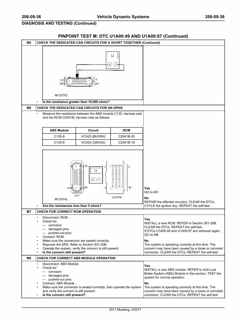
PINPOINT TEST M: DTC U1A00:49 AND U1A00:87 (Continued)M5 CHECK THE DEDICATED CAN CIRCUITS FOR A SHORT TOGETHER (Continued)
• Is the resistance greater than 10,000 ohms?
M6 CHECK THE DEDICATED CAN CIRCUITS FOR AN OPEN
• Measure the resistance between the ABS module C135, harness sideand the RCM C2041B, harness side as follows:
ABS Module Circuit RCM
C135-8 VCA23 (BU/WH) C2041B-20
C135-9 VCA24 (GN/OG) C2041B-19
• Are the resistances less than 5 ohms?
YesGO to M7.
NoREPAIR the affected circuit(s). CLEAR the DTCs.CYCLE the ignition key. REPEAT the self-test.
M7 CHECK FOR CORRECT RCM OPERATION
• Disconnect: RCM .• Check for:
— corrosion— damaged pins— pushed-out pins
• Connect: RCM .• Make sure the connectors are seated correctly.• Repower the SRS. Refer to Section 501-20B.• Operate the system, verify the concern is still present.• Is the concern still present?
YesINSTALL a new RCM. REFER to Section 501-20B.CLEAR the DTCs. REPEAT the self-test.If DTCs U1A00:49 and U1A00:87 are retrieved again,GO to M8.
NoThe system is operating correctly at this time. Theconcern may have been caused by a loose or corrodedconnector. CLEAR the DTCs. REPEAT the self-test.
M8 CHECK FOR CORRECT ABS MODULE OPERATION
• Disconnect: ABS Module .• Check for:
— corrosion— damaged pins— pushed-out pins
• Connect: ABS Module .• Make sure the connector is seated correctly, then operate the system
and verify the concern is still present.• Is the concern still present?
YesINSTALL a new ABS module. REFER to Anti-LockBrake System (ABS) Module in this section. TEST thesystem for normal operation.
NoThe system is operating correctly at this time. Theconcern may have been caused by a loose or corrodedconnector. CLEAR the DTCs. REPEAT the self-test.
206-09-36 Vehicle Dynamic Systems 206-09-36DIAGNOSIS AND TESTING (Continued)
2011 Mustang, 2/2011
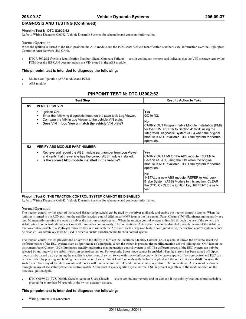
Pinpoint Test N: DTC U3002:62Refer to Wiring Diagrams Cell 42, Vehicle Dynamic Systems for schematic and connector information.
Normal OperationWhen the ignition is turned to the RUN position, the ABS module and the PCM share Vehicle Identification Number (VIN) information over the High SpeedController Area Network (HS-CAN).
• DTC U3002:62 (Vehicle Identification Number: Signal Compare Failure) — sets in continuous memory and indicates that the VIN message sent by thePCM over the HS-CAN does not match the VIN stored in the ABS module.
This pinpoint test is intended to diagnose the following:
• Module configuration (ABS module and PCM)
• ABS module
PINPOINT TEST N: DTC U3002:62Test Step Result / Action to Take
N1 VERIFY PCM VIN
• Ignition ON.• Enter the following diagnostic mode on the scan tool: Log Viewer.• Compare the VIN in Log Viewer to the vehicle VIN plate.• Does VIN in Log Viewer match the vehicle VIN plate?
YesGO to N2.
NoCARRY OUT Programmable Module Installation (PMI)for the PCM. REFER to Section 418-01, using theIntegrated Diagnostic System (IDS) when the originalmodule is NOT available. TEST the system for normaloperation.
N2 VERIFY ABS MODULE PART NUMBER
• Retrieve and record the ABS module part number from Log Viewerand verify that the vehicle has the correct ABS module installed.
• Is the correct ABS module installed in the vehicle?
YesCARRY OUT PMI for the ABS module. REFER toSection 418-01, using the IDS when the originalmodule is NOT available. TEST the system for normaloperation.
NoINSTALL a new ABS module. REFER to Anti-LockBrake System (ABS) Module in this section. CLEARthe DTC. CYCLE the ignition key. REPEAT the self-test.
Pinpoint Test O: THE TRACTION CONTROL SYSTEM CANNOT BE DISABLEDRefer to Wiring Diagrams Cell 42, Vehicle Dynamic Systems for schematic and connector information.
Normal OperationThe traction control switch (part of the hazard flasher lamp switch) can be used by the driver to disable and enable the traction control systems. When theignition is turned to the RUN position the stability/traction control (sliding car) OFF icon in the Instrument Panel Cluster (IPC) illuminates momentarily as atest. Momentarily pressing the switch disables the traction control system. When the traction control system is disabled through the use of the switch, thestability/traction control (sliding car icon) Off illuminates continuously. The conventional ABS system cannot be disabled through the use of the stability/traction control switch. If a MyKey® restricted key is in use with the AdvanceTrac® always-on feature configured to on, the traction control system cannotbe disabled. An admin key must be used in order to enable and disable the traction control system.
The traction control switch provides the driver with the ability to turn off the Electronic Stability Control (ESC) system. It allows the driver to select thedifferent modes of the ESC system, such as Sport mode (if equipped). When the switch is pressed, the stability/traction control (sliding car) OFF icon in theInstrument Panel Cluster (IPC) illuminates steadily, indicating that the traction control system is off. The different modes of the ESC system can only beselected by starting with the stability/traction control system on. For example, Sport mode cannot be enabled when the system has been turned off. Sportmode can be turned on by pressing the stability/traction control switch twice within one-half second with the brakes applied. Traction control and ESC canbe deactivated by pressing and holding the traction control switch for at least 5 seconds with the brake applied and the vehicle at a standstill. Pressing theswitch once from any of the above-mentioned modes will re-enable normal ESC and traction control operation. The conventional ABS cannot be disabledthrough the use of the stability/traction control switch. At the start of every ignition cycle, normal ESC is present regardless of the mode selected on theprevious ignition cycle.
• DTC C0089:73 (TCS Disable Switch: Actuator Stuck Closed) — sets in continuous memory and on-demand if the stability/traction control switch ispressed for more than 30 seconds or the switch actuator is stuck.
This pinpoint test is intended to diagnose the following:
• Wiring, terminals or connectors
206-09-37 Vehicle Dynamic Systems 206-09-37DIAGNOSIS AND TESTING (Continued)
2011 Mustang, 2/2011
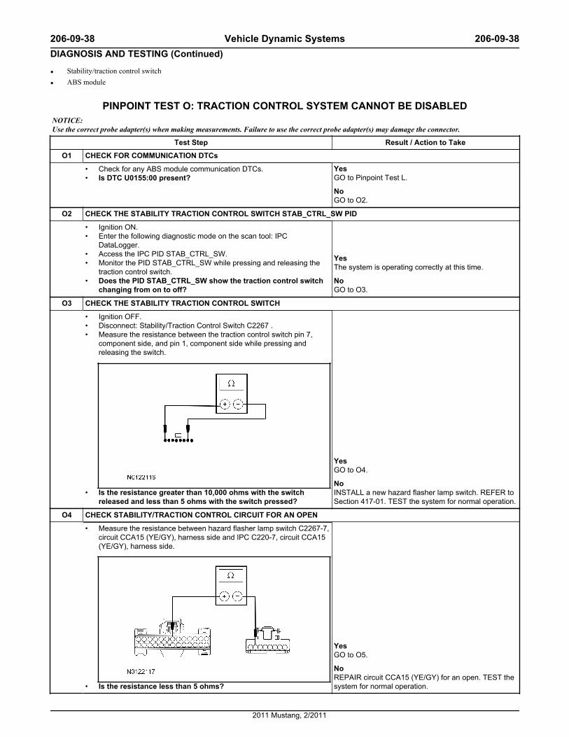
• Stability/traction control switch
• ABS module
PINPOINT TEST O: TRACTION CONTROL SYSTEM CANNOT BE DISABLEDNOTICE: Use the correct probe adapter(s) when making measurements. Failure to use the correct probe adapter(s) may damage the connector.
Test Step Result / Action to Take
O1 CHECK FOR COMMUNICATION DTCs
• Check for any ABS module communication DTCs.• Is DTC U0155:00 present?
YesGO to Pinpoint Test L.
NoGO to O2.
O2 CHECK THE STABILITY TRACTION CONTROL SWITCH STAB_CTRL_SW PID
• Ignition ON.• Enter the following diagnostic mode on the scan tool: IPC
DataLogger.• Access the IPC PID STAB_CTRL_SW.• Monitor the PID STAB_CTRL_SW while pressing and releasing the
traction control switch.• Does the PID STAB_CTRL_SW show the traction control switch
changing from on to off?
YesThe system is operating correctly at this time.
NoGO to O3.
O3 CHECK THE STABILITY TRACTION CONTROL SWITCH
• Ignition OFF.• Disconnect: Stability/Traction Control Switch C2267 .• Measure the resistance between the traction control switch pin 7,
component side, and pin 1, component side while pressing andreleasing the switch.
• Is the resistance greater than 10,000 ohms with the switchreleased and less than 5 ohms with the switch pressed?
YesGO to O4.
NoINSTALL a new hazard flasher lamp switch. REFER toSection 417-01. TEST the system for normal operation.
O4 CHECK STABILITY/TRACTION CONTROL CIRCUIT FOR AN OPEN
• Measure the resistance between hazard flasher lamp switch C2267-7,circuit CCA15 (YE/GY), harness side and IPC C220-7, circuit CCA15(YE/GY), harness side.
• Is the resistance less than 5 ohms?
YesGO to O5.
NoREPAIR circuit CCA15 (YE/GY) for an open. TEST thesystem for normal operation.
206-09-38 Vehicle Dynamic Systems 206-09-38DIAGNOSIS AND TESTING (Continued)
2011 Mustang, 2/2011
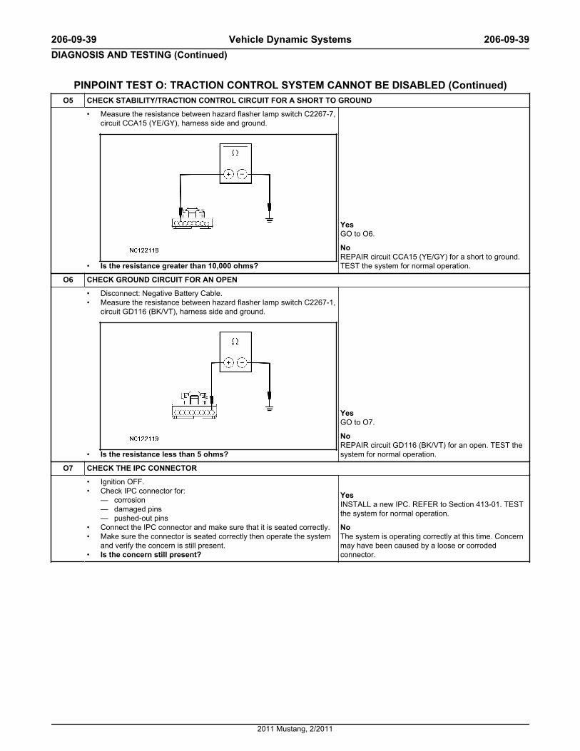
PINPOINT TEST O: TRACTION CONTROL SYSTEM CANNOT BE DISABLED (Continued)O5 CHECK STABILITY/TRACTION CONTROL CIRCUIT FOR A SHORT TO GROUND
• Measure the resistance between hazard flasher lamp switch C2267-7,circuit CCA15 (YE/GY), harness side and ground.
• Is the resistance greater than 10,000 ohms?
YesGO to O6.
NoREPAIR circuit CCA15 (YE/GY) for a short to ground.TEST the system for normal operation.
O6 CHECK GROUND CIRCUIT FOR AN OPEN
• Disconnect: Negative Battery Cable.• Measure the resistance between hazard flasher lamp switch C2267-1,
circuit GD116 (BK/VT), harness side and ground.
• Is the resistance less than 5 ohms?
YesGO to O7.
NoREPAIR circuit GD116 (BK/VT) for an open. TEST thesystem for normal operation.
O7 CHECK THE IPC CONNECTOR
• Ignition OFF.• Check IPC connector for:
— corrosion— damaged pins— pushed-out pins
• Connect the IPC connector and make sure that it is seated correctly.• Make sure the connector is seated correctly then operate the system
and verify the concern is still present.• Is the concern still present?
YesINSTALL a new IPC. REFER to Section 413-01. TESTthe system for normal operation.
NoThe system is operating correctly at this time. Concernmay have been caused by a loose or corrodedconnector.
206-09-39 Vehicle Dynamic Systems 206-09-39DIAGNOSIS AND TESTING (Continued)
2011 Mustang, 2/2011


![Broadway - Capital Pacific · 206 Broadway E Seattle, WA 98102 206 Broadway [ ] 206 Broadway . 206 Broadway Broadway is a generational ... TRANSIT SCORE 91*](https://img.pdfslide.us/doc/110x75/5ac3885d7f8b9aae1b8c7cb8/broadway-capital-broadway-e-seattle-wa-98102-206-broadway-206-broadway-.jpg)