Embed Size (px)
Citation preview
UPPCO SERVICE MANUAL Revised 5/2021 Section 2 CLEARANCES Page 1 of 18
Section 2 – Clearances
2-1 Basic Electric Clearances - Services .......................................................................... 2
2-1.1 Clearances for Electric Overhead Services .................................................................................................... 2
2-2 Miscellaneous Clearances ........................................................................................... 6
2-2.1 Wells ............................................................................................................................................................. 6
2-2.2 Private Septic Systems .................................................................................................................................. 6
2-2.3 Stored Materials ........................................................................................................................................... 6
2-2.5 Swimming Pools / Hot Tubs .......................................................................................................................... 6
2-2.6 Natural Gas Lines ......................................................................................................................................... 7
2-2.7 Natural Gas and LP and Meters ................................................................................................................... 7
2-2.8 Fuel Tanks ..................................................................................................................................................... 7
2-2.9 Class I Hazardous Locations ......................................................................................................................... 8
2-2.10 Buildings ....................................................................................................................................................... 8
2-2.11 Billboards ...................................................................................................................................................... 8
2-2.12 Special Cases ................................................................................................................................................ 8
2-3 Antenna Clearances ..................................................................................................... 8
2-4 Location of Pad mount Transformers Near Buildings ............................................... 9
2-5 Working Clearances / Protective Posts for Pad mount Transformers ................... 12
2-6 Multiple Metering ........................................................................................................ 13
2-7 Residential Deck / Other ............................................................................................. 16
2-8 Unmetered Street Lighting Decorations ................................................................... 17
2-9 CATV Power Supplies ................................................................................................ 18
UPPCO SERVICE MANUAL Revised 5/2021 Section 2 CLEARANCES Page 2 of 18
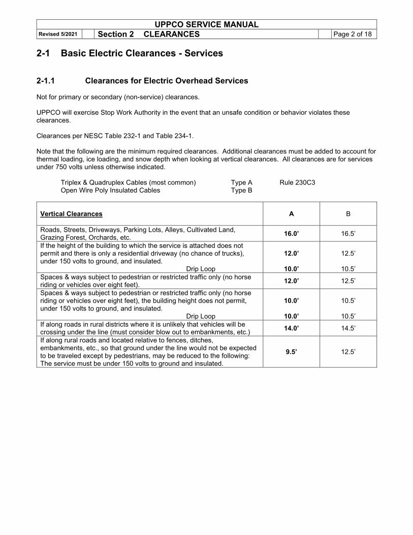
2-1 Basic Electric Clearances - Services 2-1.1 Clearances for Electric Overhead Services Not for primary or secondary (non-service) clearances. UPPCO will exercise Stop Work Authority in the event that an unsafe condition or behavior violates these clearances. Clearances per NESC Table 232-1 and Table 234-1. Note that the following are the minimum required clearances. Additional clearances must be added to account for thermal loading, ice loading, and snow depth when looking at vertical clearances. All clearances are for services under 750 volts unless otherwise indicated. Triplex & Quadruplex Cables (most common) Type A Rule 230C3 Open Wire Poly Insulated Cables Type B
Vertical Clearances
A
B
Roads, Streets, Driveways, Parking Lots, Alleys, Cultivated Land, Grazing Forest, Orchards, etc. 16.0’ 16.5’
If the height of the building to which the service is attached does not permit and there is only a residential driveway (no chance of trucks), under 150 volts to ground, and insulated.
12.0’ 12.5’
Drip Loop 10.0’ 10.5’ Spaces & ways subject to pedestrian or restricted traffic only (no horse riding or vehicles over eight feet). 12.0’ 12.5’
Spaces & ways subject to pedestrian or restricted traffic only (no horse riding or vehicles over eight feet), the building height does not permit, under 150 volts to ground, and insulated.
10.0’ 10.5’
Drip Loop 10.0’ 10.5’ If along roads in rural districts where it is unlikely that vehicles will be crossing under the line (must consider blow out to embankments, etc.) 14.0’ 14.5’
If along rural roads and located relative to fences, ditches, embankments, etc., so that ground under the line would not be expected to be traveled except by pedestrians, may be reduced to the following: The service must be under 150 volts to ground and insulated.
9.5’ 12.5’
UPPCO SERVICE MANUAL Revised 5/2021 Section 2 CLEARANCES Page 3 of 18
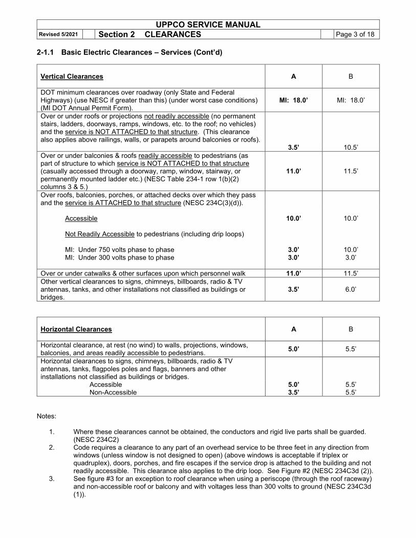
2-1.1 Basic Electric Clearances – Services (Cont’d)
Vertical Clearances
A
B
DOT minimum clearances over roadway (only State and Federal Highways) (use NESC if greater than this) (under worst case conditions) (MI DOT Annual Permit Form).
MI: 18.0’ MI: 18.0’
Over or under roofs or projections not readily accessible (no permanent stairs, ladders, doorways, ramps, windows, etc. to the roof; no vehicles) and the service is NOT ATTACHED to that structure. (This clearance also applies above railings, walls, or parapets around balconies or roofs).
3.5’ 10.5’ Over or under balconies & roofs readily accessible to pedestrians (as part of structure to which service is NOT ATTACHED to that structure (casually accessed through a doorway, ramp, window, stairway, or permanently mounted ladder etc.) (NESC Table 234-1 row 1(b)(2) columns 3 & 5.)
11.0’ 11.5’
Over roofs, balconies, porches, or attached decks over which they pass and the service is ATTACHED to that structure (NESC 234C(3)(d)).
Accessible Not Readily Accessible to pedestrians (including drip loops) MI: Under 750 volts phase to phase MI: Under 300 volts phase to phase
10.0’
3.0’ 3.0’
10.0’
10.0’ 3.0’
Over or under catwalks & other surfaces upon which personnel walk 11.0’ 11.5’ Other vertical clearances to signs, chimneys, billboards, radio & TV antennas, tanks, and other installations not classified as buildings or bridges.
3.5’ 6.0’
Horizontal Clearances
A
B
Horizontal clearance, at rest (no wind) to walls, projections, windows, balconies, and areas readily accessible to pedestrians. 5.0’ 5.5’
Horizontal clearances to signs, chimneys, billboards, radio & TV antennas, tanks, flagpoles poles and flags, banners and other installations not classified as buildings or bridges.
Accessible Non-Accessible
5.0’ 3.5’
5.5’ 5.5’
Notes:
1. Where these clearances cannot be obtained, the conductors and rigid live parts shall be guarded. (NESC 234C2)
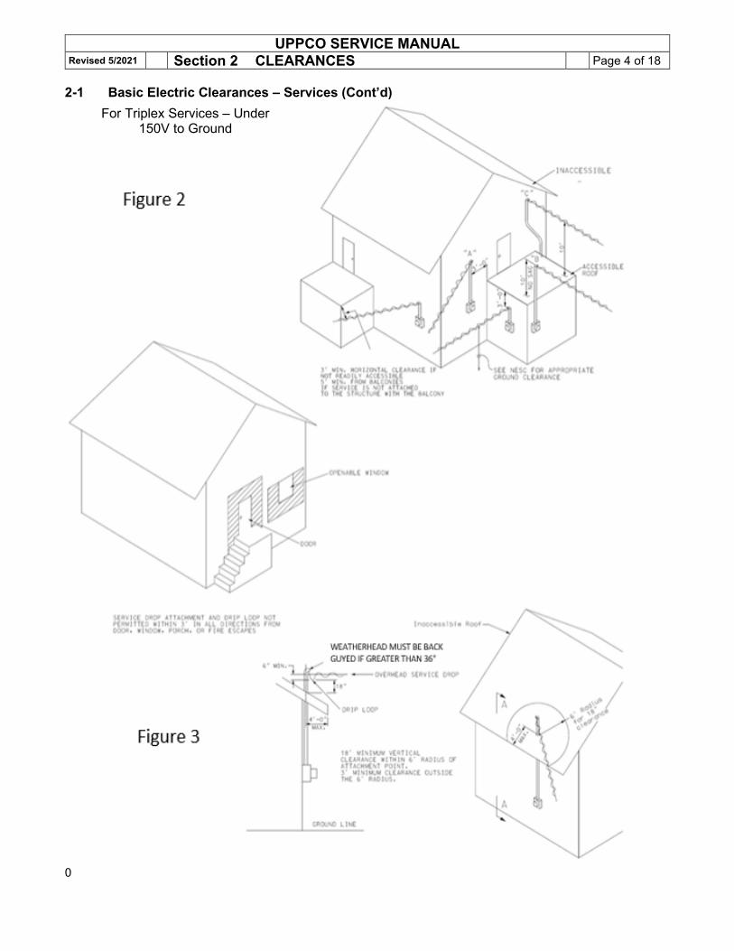
2. Code requires a clearance to any part of an overhead service to be three feet in any direction from windows (unless window is not designed to open) (above windows is acceptable if triplex or quadruplex), doors, porches, and fire escapes if the service drop is attached to the building and not readily accessible. This clearance also applies to the drip loop. See Figure #2 (NESC 234C3d (2)).
3. See figure #3 for an exception to roof clearance when using a periscope (through the roof raceway) and non-accessible roof or balcony and with voltages less than 300 volts to ground (NESC 234C3d (1)).
UPPCO SERVICE MANUAL Revised 5/2021 Section 2 CLEARANCES Page 4 of 18
2-1 Basic Electric Clearances – Services (Cont’d)
0
For Triplex Services – Under 150V to Ground
UPPCO SERVICE MANUAL Revised 5/2021 Section 2 CLEARANCES Page 5 of 18
2-1 Basic Electric Clearances – Services (Cont’d) Triplex Services Under 150 Volts to Ground
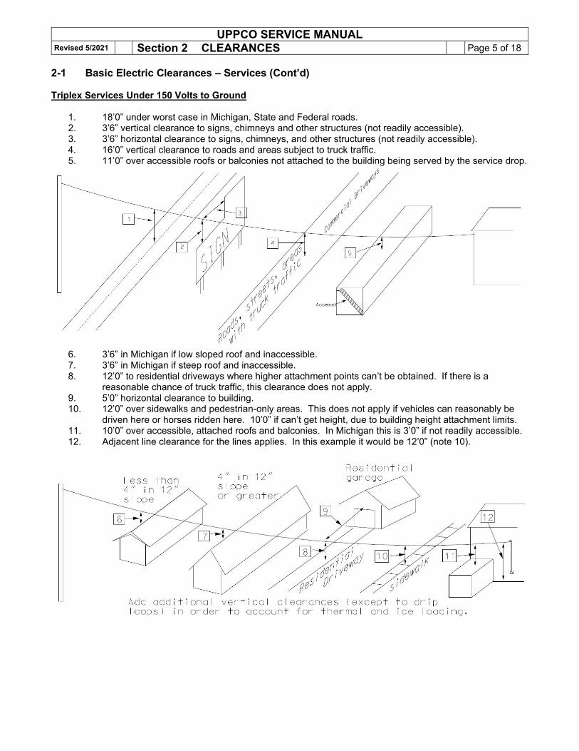
1. 18’0” under worst case in Michigan, State and Federal roads. 2. 3’6” vertical clearance to signs, chimneys and other structures (not readily accessible). 3. 3’6” horizontal clearance to signs, chimneys, and other structures (not readily accessible). 4. 16’0” vertical clearance to roads and areas subject to truck traffic. 5. 11’0” over accessible roofs or balconies not attached to the building being served by the service drop.
6. 3’6” in Michigan if low sloped roof and inaccessible. 7. 3’6” in Michigan if steep roof and inaccessible. 8. 12’0” to residential driveways where higher attachment points can’t be obtained. If there is a
reasonable chance of truck traffic, this clearance does not apply. 9. 5’0” horizontal clearance to building. 10. 12’0” over sidewalks and pedestrian-only areas. This does not apply if vehicles can reasonably be
driven here or horses ridden here. 10’0” if can’t get height, due to building height attachment limits. 11. 10’0” over accessible, attached roofs and balconies. In Michigan this is 3’0” if not readily accessible. 12. Adjacent line clearance for the lines applies. In this example it would be 12’0” (note 10).
UPPCO SERVICE MANUAL Revised 5/2021 Section 2 CLEARANCES Page 6 of 18
2-2 Miscellaneous Clearances
2-2.1 Wells Underground 5 feet for electric or gas. May be reduced to one foot with special permission and with special
precautions for lightning damage (Company Design Rule). Overhead Horizontal clearance must be considered for well maintenance. MIOSHA requires at least 10’
working clearance.
2-2.2 Private Septic Systems Clearance to holding tanks, collector tanks, drain fields, and mound systems (Company design policy): 10 feet
2-2.3 Stored Materials Overhead Overhead lines shall not be run over areas designated for material storage where cranes or other
types of tall machinery are used unless adequate clearance can be provided for full use of the equipment (Company design rule).
2-2.4 Working Clearances Following are the MIOSHA Rule 408.14005(4) rules.
Voltage Minimum personnel clearance, To any part of crane, or to the load in feet
69 kv and below 10 115 kv and 138 kv 11 345 kv 15
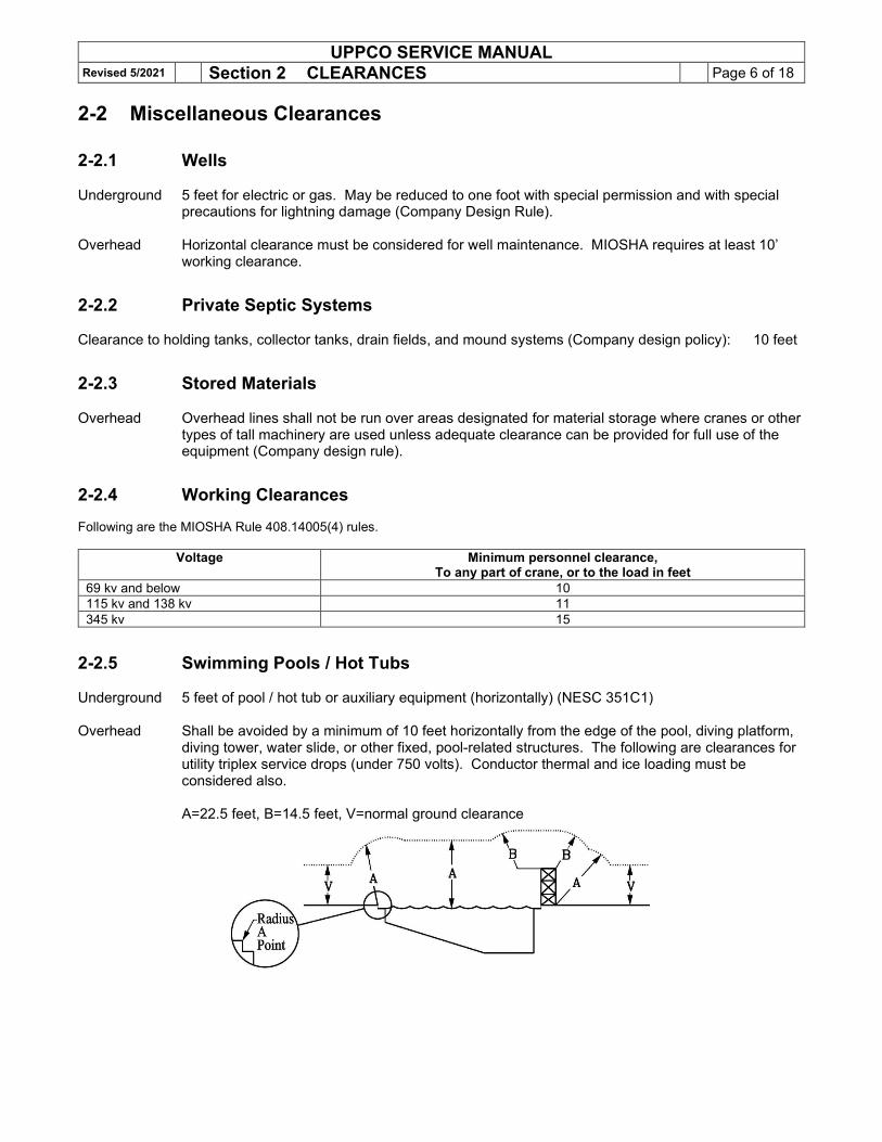
2-2.5 Swimming Pools / Hot Tubs Underground 5 feet of pool / hot tub or auxiliary equipment (horizontally) (NESC 351C1) Overhead Shall be avoided by a minimum of 10 feet horizontally from the edge of the pool, diving platform,
diving tower, water slide, or other fixed, pool-related structures. The following are clearances for utility triplex service drops (under 750 volts). Conductor thermal and ice loading must be considered also.
A=22.5 feet, B=14.5 feet, V=normal ground clearance
UPPCO SERVICE MANUAL Revised 5/2021 Section 2 CLEARANCES Page 7 of 18
2-2 Miscellaneous Clearances (Cont’d) 2-2.6 Natural Gas Lines Basic underground clearance from gas lines to all other utilities or below-ground structures is one foot.
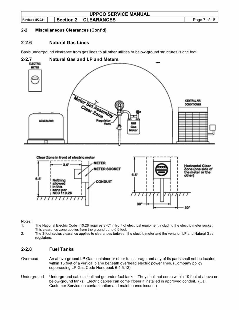
2-2.7 Natural Gas and LP and Meters
Notes: 1. The National Electric Code 110.26 requires 3’-0" in front of electrical equipment including the electric meter socket. This clearance zone applies from the ground up to 6.5 feet. 2. The 3-foot radius clearance applies to clearances between the electric meter and the vents on LP and Natural Gas
regulators.
2-2.8 Fuel Tanks Overhead An above-ground LP Gas container or other fuel storage and any of its parts shall not be located
within 15 feet of a vertical plane beneath overhead electric power lines. (Company policy superseding LP Gas Code Handbook 6.4.5.12)
Underground Underground cables shall not go under fuel tanks. They shall not come within 10 feet of above or
below-ground tanks. Electric cables can come closer if installed in approved conduit. (Call Customer Service on contamination and maintenance issues.)
UPPCO SERVICE MANUAL Revised 5/2021 Section 2 CLEARANCES Page 8 of 18
2-2.9 Class I Hazardous Locations Buried electric lines, meter sockets, CT cabinets, or termination enclosures must observe the following minimum horizontal clearances from the flammable fuel system components listed below:
Under fuel storage tanks (above or below ground) 0 feet (not allowed under the fuel tank)
Fill Pipe 10 feet Dispensing device 20 feet Remote pump 10 feet Vents 5 feet
Consult the Company for other Class I hazardous locations. (NESC 127, NEC Article 514 and NEC Article 515).
2-2.10 Buildings Underground electric lines should not be installed under buildings nor may buildings be built over underground electric lines of any voltage. (NESC 351C2 and 350.H.) (See also NEC 300-5c.)
2-2.11 Billboards The overhead service attachment and drip loop must have the following clearances from any access platform, assuming that the access platform is not accessible (no fixed access ladder or a ladder that is at least 8 feet short of the ground). The normal attachment should be on a corner of the sign. The service should not go across the face of the sign, where it might block access. NESC 234C.3.d.
3 feet below the platform (and at least 3 feet in all directions from an access ladder). 3 feet above the platform (or 3 feet out from the platform).
2-2.12 Special Cases See the Company for additional clearance requirements not listed above. Some of the items which require special clearances include the following:
Railroads Sailboat Areas Light Poles (standards) Boat Landings Grain Bins Airport Approaches Bridges Electric Transmission / Distribution Lines Catwalks Windmills/turbines
Ladders Mounted to Tall Buildings (Over 50 ft.)
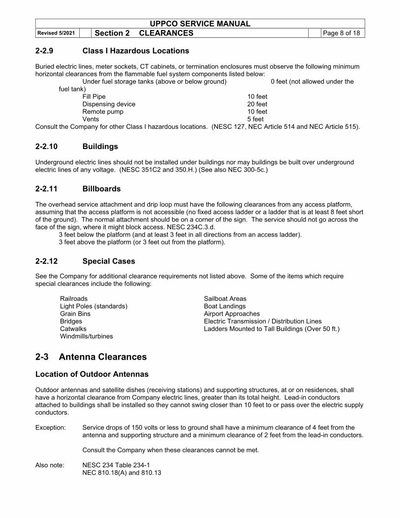
2-3 Antenna Clearances Location of Outdoor Antennas Outdoor antennas and satellite dishes (receiving stations) and supporting structures, at or on residences, shall have a horizontal clearance from Company electric lines, greater than its total height. Lead-in conductors attached to buildings shall be installed so they cannot swing closer than 10 feet to or pass over the electric supply conductors. Exception: Service drops of 150 volts or less to ground shall have a minimum clearance of 4 feet from the
antenna and supporting structure and a minimum clearance of 2 feet from the lead-in conductors.
Consult the Company when these clearances cannot be met. Also note: NESC 234 Table 234-1
NEC 810.18(A) and 810.13
UPPCO SERVICE MANUAL Revised 5/2021 Section 2 CLEARANCES Page 9 of 18
2-4 Location of Pad mount Transformers Near Buildings
See Subsection 5-11 on how to reference the window in the concrete pad. This is critical for access, switching and conduit training. Pad mount transformers cannot be located UNDER any portion of a combustible or non-combustible building or structure. Non-combustible vs. Combustible Walls Definition For the purposes of this Section, combustible walls are walls of Type No. V buildings as determined by Michigan Building Code (Construction Classification IBC Chapter 6). All other walls are considered to be non-combustible. The following is not part of code but is intended to help clarify the combustible wall definition:
Combustible Non-combustible - Wood frame - Wood frame with a brick veneer, stucco, thin layer of stone, etc. - Metal clad over a wood frame (typical pole shed)
- Masonry structures (generally a minimum of 4” thick) - Metal sheds (metal walls, metal roof, concrete floor) (can’t have wood framing for the flooring, walls, or roof) - Poured concrete walls sandwiched between Styrofoam layers (Type IB) - Heavy timber construction (non-combustible material Between timbers) (see definitions of heavy timber construction)
1. Non-combustible Walls
Pad mount oil insulated transformers shall not be located closer than 10 feet to non-combustible walls. (Company policy)
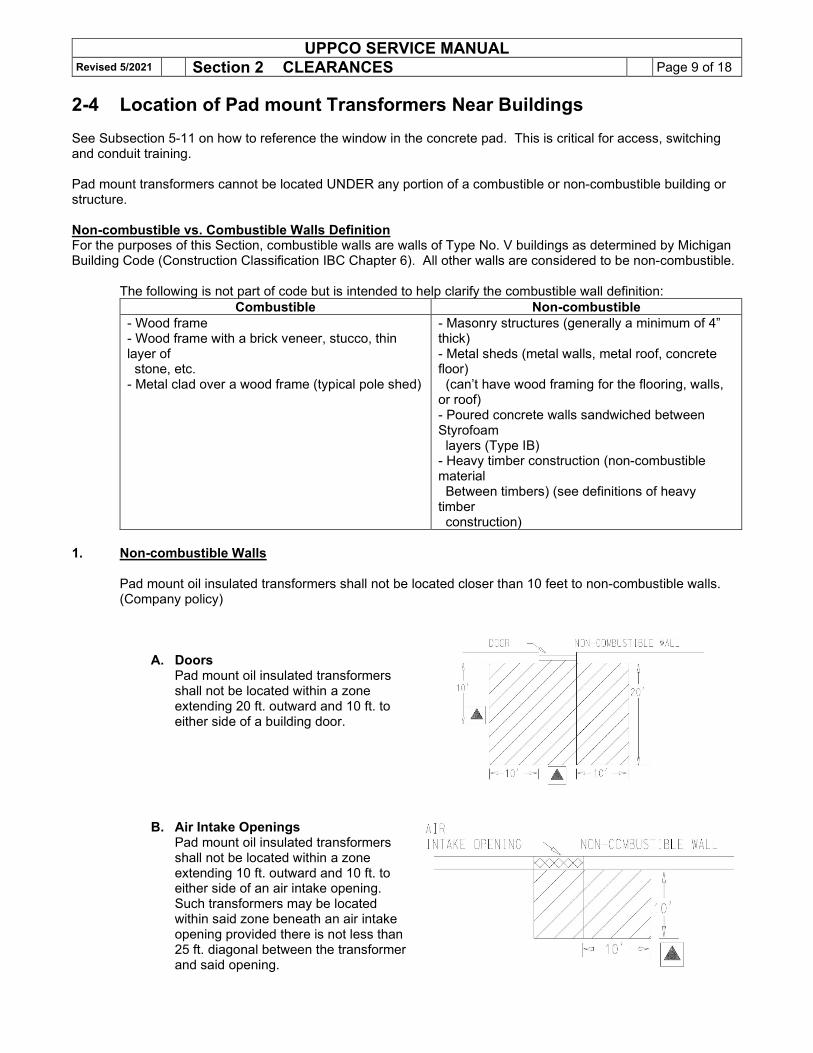
A. Doors Pad mount oil insulated transformers shall not be located within a zone extending 20 ft. outward and 10 ft. to either side of a building door.
B. Air Intake Openings Pad mount oil insulated transformers shall not be located within a zone extending 10 ft. outward and 10 ft. to either side of an air intake opening. Such transformers may be located within said zone beneath an air intake opening provided there is not less than 25 ft. diagonal between the transformer and said opening.
UPPCO SERVICE MANUAL Revised 5/2021 Section 2 CLEARANCES Page 10 of
18 2-4 Location of Pad mount Transformers Near Buildings (Cont’d)
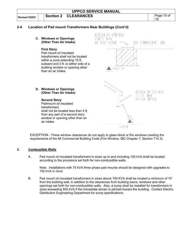
C. Windows or Openings
(Other Than Air Intake)
First Story Pad mount oil insulated transformers shall not be located within a zone extending 10 ft. outward and 3 ft. to either side of a building window or opening other than an air intake.
D. Windows or Openings (Other Than Air Intake)
Second Story Padmount oil insulated transformers shall not be located less than 5 ft. from any part of a second story window or opening other than an air intake.
EXCEPTION - These window clearances do not apply to glass block or fire windows meeting the requirements of the MI Commercial Building Code (Fire Window, IBC Chapter 7, Section 714.3).
2. Combustible Walls
A. Pad mount oil insulated transformers in sizes up to and including 100 kVA shall be located
according to the provisions set forth for non-combustible walls.
Note: Installations with 75 kVA three phase pad mounts should be designed with upgrades to 150 kVA in mind.
B. Pad mount oil insulated transformers in sizes above 100 KVA shall be located a minimum of 10’
from the building wall, in addition to the clearances from building doors, windows and other openings set forth for non-combustible walls. Also, a sump shall be installed for transformers in sizes exceeding 500 kVA if the immediate terrain is pitched toward the building. Contact Electric Distribution Engineering Department for sump specifications.
UPPCO SERVICE MANUAL Revised 5/2021 Section 2 CLEARANCES Page 11 of
18 2-4 Location of Pad mount Transformers Near Buildings (Cont’d) 3. Barriers
If the clearances specified above cannot be obtained, a fire-resistant barrier may be constructed in lieu of the separation. Based on the State Building Code, a fire-rated barrier would have to be a minimum of a 4-inch solid masonry wall or a 12-inch hollow masonry wall. If a non-combustible barrier is part of the building exterior wall, consider the impact on the eve and the potential of fire access to the roof trusses. The following methods of construction are acceptable:
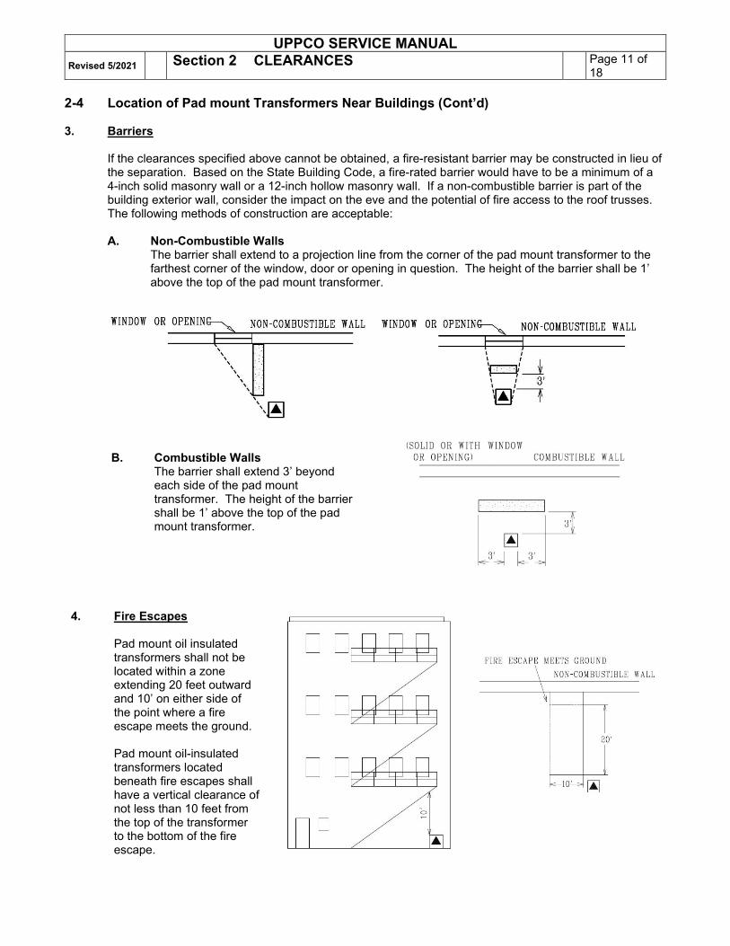
A. Non-Combustible Walls
The barrier shall extend to a projection line from the corner of the pad mount transformer to the farthest corner of the window, door or opening in question. The height of the barrier shall be 1’ above the top of the pad mount transformer.
B. Combustible Walls The barrier shall extend 3’ beyond each side of the pad mount transformer. The height of the barrier shall be 1’ above the top of the pad mount transformer.
4. Fire Escapes
Pad mount oil insulated transformers shall not be located within a zone extending 20 feet outward and 10’ on either side of the point where a fire escape meets the ground. Pad mount oil-insulated transformers located beneath fire escapes shall have a vertical clearance of not less than 10 feet from the top of the transformer to the bottom of the fire escape.
UPPCO SERVICE MANUAL Revised 5/2021 Section 2 CLEARANCES Page 12 of
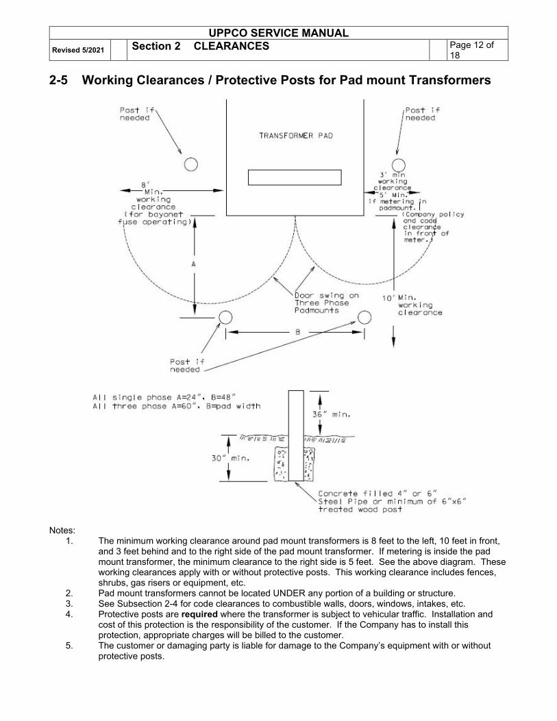
18 2-5 Working Clearances / Protective Posts for Pad mount Transformers
Notes:
1. The minimum working clearance around pad mount transformers is 8 feet to the left, 10 feet in front, and 3 feet behind and to the right side of the pad mount transformer. If metering is inside the pad mount transformer, the minimum clearance to the right side is 5 feet. See the above diagram. These working clearances apply with or without protective posts. This working clearance includes fences, shrubs, gas risers or equipment, etc.
2. Pad mount transformers cannot be located UNDER any portion of a building or structure. 3. See Subsection 2-4 for code clearances to combustible walls, doors, windows, intakes, etc. 4. Protective posts are required where the transformer is subject to vehicular traffic. Installation and
cost of this protection is the responsibility of the customer. If the Company has to install this protection, appropriate charges will be billed to the customer.
5. The customer or damaging party is liable for damage to the Company’s equipment with or without protective posts.
UPPCO SERVICE MANUAL Revised 5/2021 Section 2 CLEARANCES Page 13 of
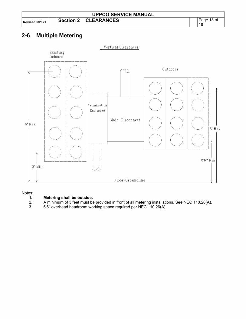
18 2-6 Multiple Metering
Notes: 1. Metering shall be outside. 2. A minimum of 3 feet must be provided in front of all metering installations. See NEC 110.26(A). 3. 6’6" overhead headroom working space required per NEC 110.26(A).
UPPCO SERVICE MANUAL Revised 5/2021 Section 2 CLEARANCES Page 14 of
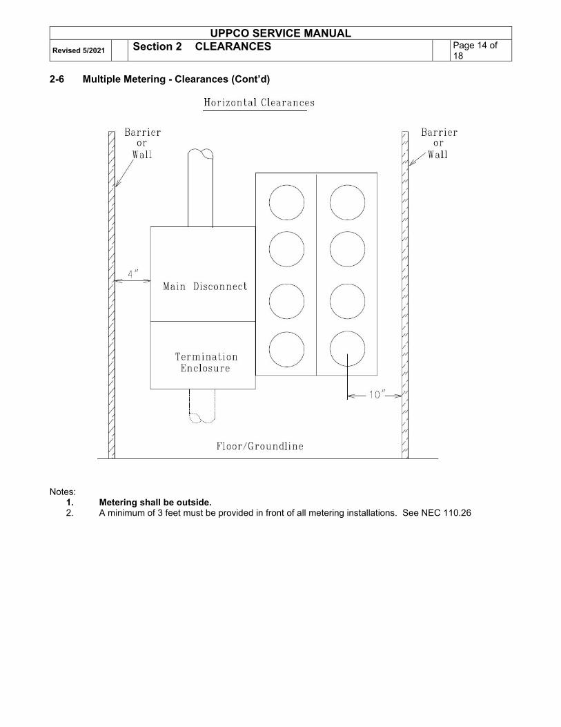
18 2-6 Multiple Metering - Clearances (Cont’d)
Notes: 1. Metering shall be outside. 2. A minimum of 3 feet must be provided in front of all metering installations. See NEC 110.26
UPPCO SERVICE MANUAL Revised 5/2021 Section 2 CLEARANCES Page 15 of
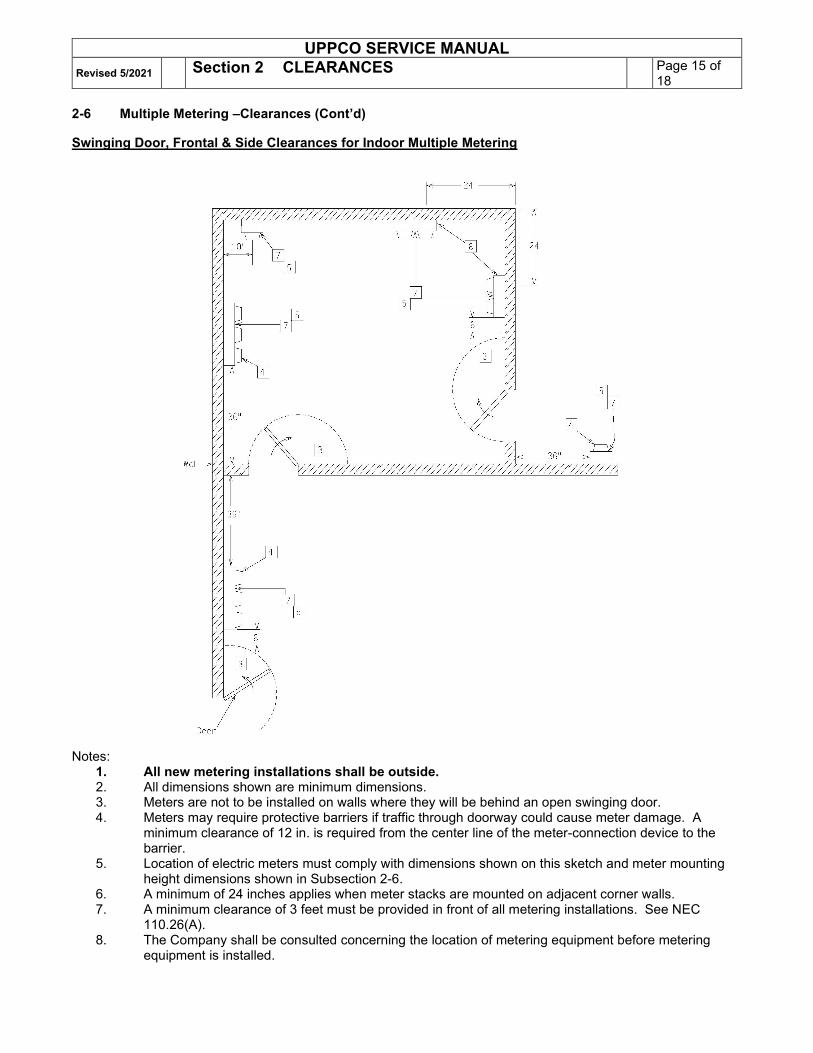
18 2-6 Multiple Metering –Clearances (Cont’d) Swinging Door, Frontal & Side Clearances for Indoor Multiple Metering
Notes:
1. All new metering installations shall be outside. 2. All dimensions shown are minimum dimensions. 3. Meters are not to be installed on walls where they will be behind an open swinging door. 4. Meters may require protective barriers if traffic through doorway could cause meter damage. A
minimum clearance of 12 in. is required from the center line of the meter-connection device to the barrier.
5. Location of electric meters must comply with dimensions shown on this sketch and meter mounting height dimensions shown in Subsection 2-6.
6. A minimum of 24 inches applies when meter stacks are mounted on adjacent corner walls. 7. A minimum clearance of 3 feet must be provided in front of all metering installations. See NEC
110.26(A). 8. The Company shall be consulted concerning the location of metering equipment before metering
equipment is installed.
UPPCO SERVICE MANUAL Revised 5/2021 Section 2 CLEARANCES Page 16 of
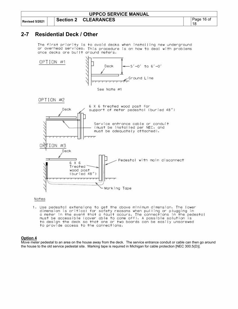
18 2-7 Residential Deck / Other
Option 4 Move meter pedestal to an area on the house away from the deck. The service entrance conduit or cable can then go around the house to the old service pedestal site. Marking tape is required in Michigan for cable protection [NEC 300.5(D)].
UPPCO SERVICE MANUAL Revised 5/2021 Section 2 CLEARANCES Page 17 of
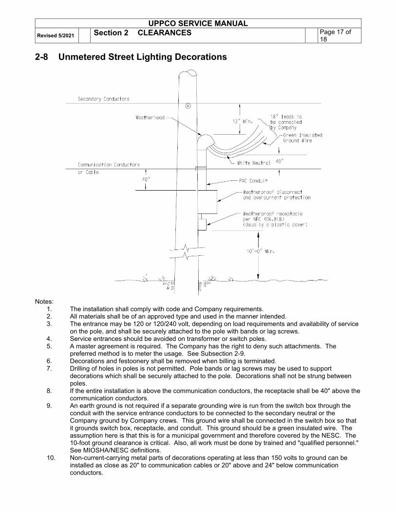
18 2-8 Unmetered Street Lighting Decorations
Notes:
1. The installation shall comply with code and Company requirements. 2. All materials shall be of an approved type and used in the manner intended. 3. The entrance may be 120 or 120/240 volt, depending on load requirements and availability of service
on the pole, and shall be securely attached to the pole with bands or lag screws. 4. Service entrances should be avoided on transformer or switch poles. 5. A master agreement is required. The Company has the right to deny such attachments. The
preferred method is to meter the usage. See Subsection 2-9. 6. Decorations and festoonery shall be removed when billing is terminated. 7. Drilling of holes in poles is not permitted. Pole bands or lag screws may be used to support
decorations which shall be securely attached to the pole. Decorations shall not be strung between poles.
8. If the entire installation is above the communication conductors, the receptacle shall be 40" above the communication conductors.
9. An earth ground is not required if a separate grounding wire is run from the switch box through the conduit with the service entrance conductors to be connected to the secondary neutral or the Company ground by Company crews. This ground wire shall be connected in the switch box so that it grounds switch box, receptacle, and conduit. This ground should be a green insulated wire. The assumption here is that this is for a municipal government and therefore covered by the NESC. The 10-foot ground clearance is critical. Also, all work must be done by trained and "qualified personnel." See MIOSHA/NESC definitions.
10. Non-current-carrying metal parts of decorations operating at less than 150 volts to ground can be installed as close as 20" to communication cables or 20" above and 24" below communication conductors.
UPPCO SERVICE MANUAL Revised 5/2021 Section 2 CLEARANCES Page 18 of
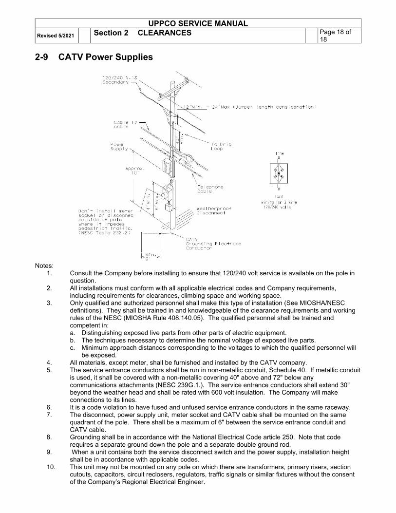
18 2-9 CATV Power Supplies
Notes:
1. Consult the Company before installing to ensure that 120/240 volt service is available on the pole in question.
2. All installations must conform with all applicable electrical codes and Company requirements, including requirements for clearances, climbing space and working space.
3. Only qualified and authorized personnel shall make this type of installation (See MIOSHA/NESC definitions). They shall be trained in and knowledgeable of the clearance requirements and working rules of the NESC (MIOSHA Rule 408.140.05). The qualified personnel shall be trained and competent in: a. Distinguishing exposed live parts from other parts of electric equipment. b. The techniques necessary to determine the nominal voltage of exposed live parts. c. Minimum approach distances corresponding to the voltages to which the qualified personnel will
be exposed. 4. All materials, except meter, shall be furnished and installed by the CATV company. 5. The service entrance conductors shall be run in non-metallic conduit, Schedule 40. If metallic conduit
is used, it shall be covered with a non-metallic covering 40" above and 72" below any communications attachments (NESC 239G.1.). The service entrance conductors shall extend 30" beyond the weather head and shall be rated with 600 volt insulation. The Company will make connections to its lines.
6. It is a code violation to have fused and unfused service entrance conductors in the same raceway. 7. The disconnect, power supply unit, meter socket and CATV cable shall be mounted on the same
quadrant of the pole. There shall be a maximum of 6" between the service entrance conduit and CATV cable.
8. Grounding shall be in accordance with the National Electrical Code article 250. Note that code requires a separate ground down the pole and a separate double ground rod.
9. When a unit contains both the service disconnect switch and the power supply, installation height shall be in accordance with applicable codes.
10. This unit may not be mounted on any pole on which there are transformers, primary risers, section cutouts, capacitors, circuit reclosers, regulators, traffic signals or similar fixtures without the consent of the Company’s Regional Electrical Engineer.