Embed Size (px)
Citation preview
Design Guidelines February 2020: Issue 5
ucw UNIVERSITY OF
CANTERBURY Te Whare Wiinanga o Waitaha CHRISTCHURCH NEW ZEALAND
Section 2
Architecture.
www.canterbury.ac.nz/learningresources
Standards in the Design Guidelines Suite
Design Guidelines Index:
01 General
02 Architecture
03 Audio Visual
04 Civil
05 Communication Cabling
06 Design for Access and Mobility
07 Documentation Standards
08 Electrical
09 Environmentally Sustainable Design (ESD)
10 Fire and Life Safety
11 Interior Design
12 Hydraulics
13 Infrastructure
14 Landscaping
15 Lifts
16 Mechanical
17 Metering and Controls
18 Security
19 Signage and Wayfinding
20 Structure and Seismic
Document Control
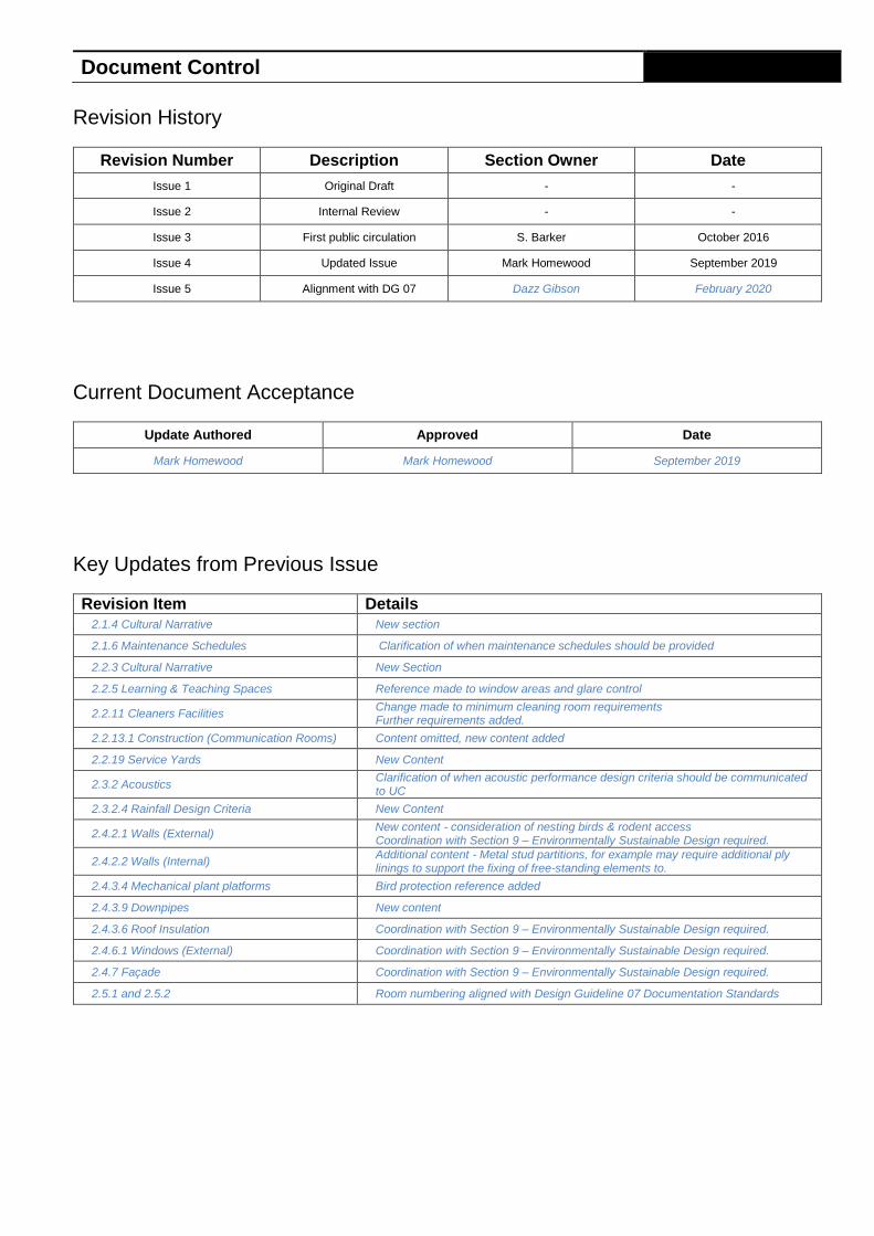
Revision History
Revision Number Description Section Owner Date
Issue 1 Original Draft - -
Issue 2 Internal Review - -
Issue 3 First public circulation S. Barker October 2016
Issue 4 Updated Issue Mark Homewood September 2019
Issue 5 Alignment with DG 07 Dazz Gibson February 2020
Current Document Acceptance
Update Authored Approved Date
Mark Homewood Mark Homewood September 2019
Key Updates from Previous Issue
Revision Item Details
2.1.4 Cultural Narrative New section
2.1.6 Maintenance Schedules Clarification of when maintenance schedules should be provided
2.2.3 Cultural Narrative New Section
2.2.5 Learning & Teaching Spaces Reference made to window areas and glare control
2.2.11 Cleaners Facilities Change made to minimum cleaning room requirements Further requirements added.
2.2.13.1 Construction (Communication Rooms) Content omitted, new content added
2.2.19 Service Yards New Content
2.3.2 Acoustics Clarification of when acoustic performance design criteria should be communicated to UC
2.3.2.4 Rainfall Design Criteria New Content
2.4.2.1 Walls (External) New content - consideration of nesting birds & rodent access
Coordination with Section 9 – Environmentally Sustainable Design required.
2.4.2.2 Walls (Internal) Additional content - Metal stud partitions, for example may require additional ply linings to support the fixing of free-standing elements to.
2.4.3.4 Mechanical plant platforms Bird protection reference added
2.4.3.9 Downpipes New content
2.4.3.6 Roof Insulation Coordination with Section 9 – Environmentally Sustainable Design required.
2.4.6.1 Windows (External) Coordination with Section 9 – Environmentally Sustainable Design required.
2.4.7 Façade Coordination with Section 9 – Environmentally Sustainable Design required.
2.5.1 and 2.5.2 Room numbering aligned with Design Guideline 07 Documentation Standards
Contents
Overview 1
2.1.1 Purpose 1
2.1.2 Key Design Principles 1
2.1.3 Key Design Principles 1
2.1.4 Cultural Narrative 1
2.1.5 Space Allocation and Utilisation 2
2.1.6 Maintenance Schedules 2
Space Planning 2
2.2.1 Circulation 2
2.2.2 Access floors 2
2.2.3 Cultural Narrative 2
2.2.4 Building Siting 2
2.2.5 Ceiling Heights and Spaces 2
2.2.6 Learning & Teaching Spaces 2
2.2.7 Laboratories 2
2.2.8 Library Spaces 2
2.2.9 Enclosed offices 2
2.2.10 Open plan offices 2
2.2.11 Cleaners Facilities 2
2.2.12 Plantrooms 2
2.2.13 Communications Rooms 3
2.2.14 Basements 4
2.2.15 Service Tunnels and Crawlways 4
2.2.16 Heat and Eat Facilities 4
2.2.17 Informal Learning Zones 4
2.2.18 Café / Retail Areas 4
General Design Considerations 5
2.3.1 Purpose 5
2.3.2 Acoustics 5
Building Elements 7
2.4.1 Floors 7
2.4.2 Walls 7
2.4.3 Roof 8
2.4.4 Stairs and Ramps 9
2.4.5 Doors 9
2.4.6 Windows 11
2.4.7 Façade 12
Numbering & Labelling 12
2.5.1 Buildings 12
2.5.2 Room Identification 13
Compliance Checklist 14
0
2.1 Overview
University of Canterbury – Section 02. Architecture – Design Guidelines September 2019: Issue 4
Page 1 of 20
Overview
2.1.1 Purpose
The architecture section provides a reference document to support consistency across design and engineering objectives, providing guidance on the minimum performance standards for architectural design and the maintenance legacy placed on the building owner that results from them.
This section of the Design Guidelines is intended to be read and implemented in design in conjunction with Section 01 – General and any project specific brief and agreements.
Section 11 - Interior Design
Whilst it is expected that consultants working at the University of Canterbury will be familiar with the full suite of the Design Guidelines - Architectural consultants shall in particular refer to the requirements put forward in Section 11 - Interior Design, as there are many interfacing elements.
2.1.2 Key Design Principles
Key objectives of this section are to encourage good design decisions, with a particular emphasis on value for money and the design of low maintenance flexible facilities/buildings that will perform well over the course of their intended life span.
Consultants must design buildings and engineering services that are energy efficient, meet sustainability criteria, and develop spaces that support the everyday functions of the University.
In general terms the following key design principles shall be applied:
● Space planning shall consider future flexibility by adopting an open plan floor layout with careful consideration given to structural grids, column locations, stair/lift shafts, vertical services shafts and the penetration of natural light
● Load bearing built elements that restrict future flexibility should be confined wherever possible to the building core or external walls leaving the interior open and uncluttered
● Building design shall assume maximum occupancy levels with appropriate circulation and ancillary spaces provided
● New work space layouts and their physical dimensions must conform to the principles documented in the University of Canterbury Space Allocation Policy document
● Building services must be designed/configured to support easy access and modification
● Consideration must be given to the space allocation for services reticulation in horizontal and vertical tunnels/ducts and ceiling voids to ensure ease of access for maintenance and future changes
● Cognisance in the design of the importance of ease of access between buildings, the significance of wind tunnelling/turbulence and the need to include appropriate wayfinding and visual cues to aid in understanding and navigating through the campus
● The design shall eliminate the risk of vermin and the roosting of nuisance birds such as pigeons.
2.1.3 Key Design Principles
Key objectives of this section are to encourage good design decisions, with a particular emphasis on value for money and the design of low maintenance flexible facilities/buildings that will perform well over the course of their intended life span.
2.1.4 Cultural Narrative
UC Strategy for Maori Development
Designs and the design process is to be consistent with the UC Strategy for Māori Development that recognises the special relationship with Ngāi Tahu and UC’s commitment to explore common interests.
Designs are to support UC’s recognition of the indigenous people of Aotearoa by including cultural interpretation and representation in its physical spaces, signage and space planning across the campus in conjunction with Ngāi Tahu and Ngāi Tūāhuriri.
UC Cultural Narrative
The UC Cultural Narrative provides insight into what is important to Ngāi Tūāhuriri in the Campus Master Plan and how the narratives of genealogy, values and stories might inform the layout of the campus, the movement of people, and the design and naming of space. The UC Cultural Narrative is a primary reference for architectural consultants.
The elements of these narratives that are most important to Ngāi Tūāhuriri are to be recognised and reflected in the design of new spaces. These important elements include: people, land, clean waterways, feeding and food preparation and a sense of community and belonging, landmarks, navigation, wayfinding and the naming of places.
The Cultural Narrative acknowledges that further work will be required to provide specific advice for specific spaces, buildings and projects.
Matapopore Urban Design Guide
The UC Cultural Narrative refers to the Matapopore Urban Design Guide that was developed to provide a guide on how Ngāi Tūāhuriri historical narratives and values might be expressed in a contemporary urban environment. This Design Guide is based on cultural values and stories rather than being technical and prescriptive. It is a primary reference for the inclusion of the cultural native into the development of the UC campus.
Design should be informed by and reflect the foundation principles – kaupapa- that are consistent with the historical narrative. These are described in detail on the Design Guide and include:
Whakapapa – identify and place Mahinga kai – food gathering practices and places Mana Motuhake – tribal identity Manaakitanga – hospitality Ture Wairua – spirituality Raupapa – co-design Tangata –the right people
Architectural consultants are to note that raupaka expects a design process that has engagement with Ngāi Tūāhuriri from the start to the end and involvement to the level of co-design.
UC will work with consultants to assist with engagement of the people with appropriate genealogical connection and

2.1 Overview
University of Canterbury – Section 02. Architecture – Design Guidelines September 2019: Issue 4
Page 2 of 20
standing in Ngāi Tūāhuriri to be involved in the design process.
2.1.5 Space Allocation and Utilisation
All designs are to be in accordance with the University of Canterbury Space Allocation Policy.
The Space Planning Requirements produced by the Tertiary Education Facilities Management Association (TEFMA) have been specifically developed to provide a base recommendation for space planning by designers in the higher education sector.
For all designs of buildings or facilities which incorporate teaching areas at the University of Canterbury, either new or refurbished, shall include a clear comparison of the spacial provisions provided in the design in comparison to the recommendations of the TEFMA Space Planning Requirements, and the University of Canterbury Space Allocation Policy.
2.1.6 Maintenance Schedules
A repetitive theme in the design Guidelines in the need for detailed consideration of maintenance - arising from the fact that the University is not a conventional property developer since it will typically own a building from design, through refurbishment and or extension through to demolition.
In particular the University is adverse to façade and other exterior solutions which require extensive or frequent scheduled maintenance.
The design consultant is required to submit a Maintenance Schedule covering key elements such as the roof and façade at the end of the Developed Design stage for consultation and approval from the University. This should be included in the Design Presentations and Coordination Workshops referenced in Section 1.5.
2.2 Space Planning
University of Canterbury – Section 02. Architecture – Design Guidelines September 2019: Issue 4
Page 2 of 20
Space Planning
2.2.1 Circulation
Lobby and corridor size and width shall be set to allow for high level use periods and be aligned with the maximum design capacity of building.
Lifts shall be provided in all multi-level buildings
2.2.2 Access floors
Access floors can be used for communication rooms or computer laboratories if required.
The University has no preference for any particular design other than it should be robust, seismically restrained and easy to use and maintain.
2.2.3 Cultural Narrative
Designs are to meet the expectations of the UC Strategy for Māori Development. Designers are expected to engage with Ngāi Tūāhuriri in a way consistent with their expectation as set out in the Matapopore Design Guide.
Architectural consultants are expected to include elements of the Cultural Narrative and its foundation principles where these are appropriate to the project. Designs should reflect and include where relevant the elements of genealogy, values and stories described in the UC Cultural Narrative.
2.2.4 Building Siting
Where possible new buildings will be located and orientated on a site to maximize natural light, views, and ease of access and evacuation to a safe place, sensitive to natural features on campus such as greenspaces and walkways.
2.2.5 Ceiling Heights and Spaces
In general, the minimum acceptable ceiling height shall be not less than 2700mm.
The minimum clearance in the ceiling space to the underside of the slab or roof structure over shall be not less than 400mm.
2.2.6 Learning & Teaching Spaces
The following requirements are provided to inform space allocation for a variety of teaching spaces. Specific requirements that are different from the default will be advised through Client liaison/briefing:
● Classrooms - 2m² per person
● Lecture room/theatre - 150 to 600 seats 1m²/seat
● Lectorial Spaces - 2.5m2 per person
● Bio-box - from plus 30 m² to 75 m²
● Computer Laboratories – 3 to3.5m² per station
● Computer Room/V lab style - 4m² per station
● Science Laboratories - 4m² per person
Teaching areas shall be designed to support people with disabilities with satisfactory access provided to all equipment.
In designing tier-floored lecture theatres, provision should be made for a proportion of the seating area to be accessible to disabled persons. Space should be provided so that wheelchair users can remain seated in their wheelchairs.
Careful consideration should be given to the extent and control of sunlight, brightness and glare etc. within all teaching and learning spaces.
2.2.7 Laboratories
Effective design solutions are founded on a clear understanding of the regular practice and procedures that each laboratory must support.
Each laboratory must be evaluated on a case by case basis to determine any need for special consideration beyond any perceived generic solution. This includes the need to agree the performance of any materials used.
For all laboratory projects relevant technical and Health & Safety staff should be consulted to inform the space brief.
2.2.8 Library Spaces
For major projects, particularly if the building is off the main Ilam Campus, library staff must be consulted for space requirements for the delivery of their services.
Even where a library is not part of the Brief, there may be a need to provide additional library services.
2.2.9 Enclosed offices
Locate enclosed offices to areas either adjacent to the building’s core or away from the building’s perimeter and, where possible, facing sources of natural light.
2.2.10 Open plan offices
Open plan work areas will generally be a mixture of individual and shared work zones and must be inherently capable of accommodation alternative layouts as easily as possible.
The building perimeter should be prioritised for use as open, flexible work spaces to maximize the potential for natural light and outlook.
Work Zones
Work zones may include a combination of:
● Open plan, individual work points
● Informal breakout areas
● Meeting carrels and quiet zones
● Team tables
● Multipurpose meeting and project rooms
● Shared storage and utility hubs
2.2.11 Cleaners Facilities
One Cleaner’s Store is to be provided for each building on the ground floor accessible to entry/exits for receiving delivery of cleaning goods, and storage for laundry awaiting collection (hand towel rolls). Minimum size of this room is to be minimum of 2.000m wide x 2.500m long.
One Cleaner’s Room is to be positioned on each floor of new and refurbished buildings. Minimum size is to be 1.000m wide x 2.000m long. Larger facilities at ground floor would be preferable to full sized storage on upper floors.
Specialty cleaning equipment (relevant to specific building requirements) are to be housed separately, with plumbing connections as required.
Refer to 11.5.6 for storage, tapware and sink requirements.
2.2.12 Plantrooms

2.2 Space Planning
University of Canterbury – Section 02. Architecture – Design Guidelines September 2019: Issue 4
Page 3 of 20
Ease and efficiency in the maintenance of plant and equipment is a key requirement for the University. To facilitate this all Plantrooms are to be sufficiently sized to allow unhindered access to all equipment by maintenance personnel and contractors. Plant rooms shall be fully integrated both aesthetically and functionally into the building design.
Plant rooms are required to provide protection for mechanical plant and equipment from mechanical damage, weather or tampering by unauthorised personnel.
Location of plant rooms within buildings shall take into consideration the most direct point of vehicular access which can be achieved without the introduction of extensive service road connections.
Stairway and/or full door access shall be provided to upper level plant rooms. Roller door and/or full door access shall be provided to ground level plant rooms. Access shall enable existing and future equipment to be removed and installed.
Plant in ceiling spaces or confined spaces will only be permitted with University approval, and must comply with Occupational Health and Safety requirements.
Basement plant rooms are not approved due to possibility of flooding.
Plant room floors shall be well graded to drain and provided with floor outlets of not less than 75mm diameter to permit hosing down. Floors shall be of impervious coat finish. Plant rooms shall be provided (where required) with mechanical exhaust ventilation.
Plant rooms shall be well lit with fluorescent lighting, and provided with a minimum of two (2) single phase GPO’s and one (1) three phase 5 wire 30 Amp welding outlet for maintenance use. Large plant rooms may require additional single phase GPO’s to ensure adequate coverage is available to all areas of the room.
A sign indicating plant room shall be provided on the face of the plant room door.
Full concrete plinths shall be provided under all floor mounted equipment. Partial concrete pads are not permitted.
The Consultant shall nominate in the schematic design the percentage allowed for future expansion.
2.2.13 Communications Rooms
A Communication Room is to be provided on each level of new or refurbished buildings, located so that access to the room is directly from hallways / corridors.
Communication rooms are to house communication equipment related for the operation of the following services:
● Wired and wireless data networks
● VoIP/copper telephone system
● Emergency lighting equipment
● Security Control Panels
Communication rooms that are shared with other services such as AV will require lockable rack equipment. Additional space will need to be allocated to the above dimensions when secure racks are to be used.
The racks installed in the Communications Room are standard and built to University specifications. Refer to Section 05. Communication Cabling for details. Access is required at the front and back of each rack.
The University has nominated three standard room sizes that accommodate space for the racks themselves and
appropriate access for maintenance. Small buildings such as campus houses may have secure wall mounted cabinets installed.
The preferred size for use at the University is nominated as Communications Room Type 1. However if larger capacity is required then Communications Room Type 2 could be used, and likewise, if smaller capacity is appropriate then Communications Room 3 should be used. Small building such as campus houses may have secure wall mounted cabinets installed. Where space restrictions exist IT Networks can approve or provide alternative designs.
Refer to the minimum dimensions shown on the Standard Plan layouts below:
Communications Room Type 1 (Output capacity-624, includes: 1 x Equipment rack, 1 x Outlet rack)
Communications Room Type 2 (Output capacity-1248, includes: 2 x Equipment racks, 2 x Outlet racks)
Communications Room Type 3 (Output capacity-312, includes: 1xTop half equipment, 1xBottom half for outlets)
Construction
2.2 Space Planning
University of Canterbury – Section 02. Architecture – Design Guidelines September 2019: Issue 4
Page 4 of 20
A ceiling is not required in communication rooms.
Walls to communication room are to extend to the underside of the floor above. Finish to all communications room walls is screw fixed 12mm v-joined plywood, paint finish.
Communications room floor is to be paint finish or anti-static vinyl finish and is to be installed before the racks are installed.
A door closer shall be fitted to all communication rooms.
Communication rooms should not be shared by other services aside from building management services. If co-location is unavoidable, lockable cabinets must be used. Additional space will need to be allocated to the room dimensions when secure racks are to be used.
The communications room shall not have any signage that identifies the room’s purpose.
Care shall be taken in the design/construction of the room to ensure it is not possible to gain access to the room via a cable pathway or overhead plenum space.
All rack equipment must be seismically mounted with a PS1 producer statement provided. sit on seismic frames, with raised a suitable distance above floor level to meet floor avoidance requirements.
Reference Section 05 Communication cabling / Pathways for requirements for cable trays and penetrations into comms rooms.
Reference Section 05 Communication cabling/ Temperature control for requirements for operating environment management.
Reference Section 05 Communication cabling/ Security for security access requirements for comms rooms.
2.2.14 Basements
Where basements are considered in space planning (particularly where occupied) allowance shall be made for a drained cavity to the floor and all walls - in case of tanking failure.
2.2.15 Service Tunnels and Crawlways
Crawlways and tunnels shall be constructed of in-site reinforced concrete or waterproof pre-cast concrete. They must be configured to maximise ease of access to all services that pass through them and shall ensure that all health and safety issues associated with a confined space are considered and addressed as much as reasonably practical.
Minimum sizes are:
● Tunnels 2.560 metres high by 2.000 metres wide
● Crawlways 1.500 metres high by 2.000 metres wide
Crawlways shall only be used where height limitations preclude the provision of tunnels.
Walls and ceilings of crawlways and tunnels shall be fitted with cast-in “Unistrut” P1000 at 1.250 metre centres.
Crawlways and tunnels are required to be naturally and/or mechanically ventilated to maintain temperatures below a peak figure of 35°C.
2.2.16 Heat and Eat Facilities
A ‘Heat and Eat’ facility is to be located into at least one student social area per building.
‘Heat and Eat’ facilities should be integrated into the student social area and not be an enclosed room.
Refer to Section 11. Interior Design for detailed room requirements.
2.2.17 Informal Learning Zones
Section under development. These areas are to be specifically discussed with the University Project Manager on a case-by-case basis.
Informal learning zones can include; student lounges, common rooms, articulated corridor areas, project rooms and other flexible multi-use spaces.
2.2.18 Café / Retail Areas
These areas are to be specifically discussed with the University Project Manager on a case-by-case basis with reference to the UC Retail Plan.
2.2.19 Service Yards
Buildings are to provide rubbish and recycling zones, external to the building, with sufficient storage for 6 sealed 240L bins. Service yards are to be sensitively located and appropriately.

2.3 General Design Considerations
University of Canterbury – Section 02. Architecture – Design Guidelines September 2019: Issue 4
Page 5 of 20
General Design Considerations
2.3.1 Purpose
Key Functional Requirements
Key end user functional requirements that should be considered include:
● Quiet/focused individual tasks
● Storage for a range of resources and artefacts
● Adequate and appropriate levels of security for building occupants
● Links with adjoining buildings
● Spaces that accommodate dual functions to maximize efficiency of use and occupancy
● The effective segregation/screening of noisy activities from quieter non-related functions in an open plan environment
● The provision of adequate support space for filing, photocopying, storage etc
● Efficient, effective and adequate circulation space
● Consideration of future flexibility to support new technology
● The use of modular systems for consistency and cost effectiveness
2.3.2 Acoustics
It is an absolute necessity to understand and manage the consequences of noise within confined spaces (reverberation) and more generally the transfer through working buildings whether airborne or via the structural frame.
This interrogation must be completed in the design stage to ensure that appropriate steps are taken to mitigate any negative effects through the specification and application of materials and the development of suitable details.
The relevance of acoustics must be considered on a space by space basis firstly by establishing the intended use of the room and then determining whether activity within it either generates excessive noise or is susceptible to it.
Some spaces will require consideration of acoustic performance with respect to speech clarity and volume and will need to be optimised for Audio Visual equipment and systems.
The Acoustic Performance design criteria and approaches should be included in the Design Presentation and Coordination workshops as referenced in Section 1.5.
Teaching Spaces
The overall acoustic design of a typical teaching space should provide a minimum 50dB attenuation of ambient noise.
Acoustic design wall and wall panels are recommended for reducing reverberation of sound in teaching spaces. Acoustic specialist advice should be sought when considering audio acoustic quality.
Ambient sound in a teaching space should not contain any distinctive characteristics such as tones or fluctuations.
Air conditioning, external noise and other plant noise should not exceed NR25 as defined by AS2107 1987.
The construction of any teaching space must ensure that it is not excessively reverberant.
A speech transmission index rating (STI) of 0.76 or better is desirable for clear intelligible speech.
Acoustic treatment to strategic areas for the room (dampening) may be incorporated as decorative wall finishes or even artwork.
Objective Values of Sound Reduction and Subjective Impressions
Privacy Classes shall be defined as follows:
● Class 1 Professorial Suites, Teaching Areas, Seminar Rooms and Conference Rooms
● Class 2 Readers, Lecturers, Common Rooms
● Class 3 Tutors Rooms, Stores, General Office
Privacy Class
Sound insertion Loss Values Subjective impression
Walls and
ceilings
Walls with
doors
Doors Only
Class 1 40 dB 35 dB 25 dB High degree of privacy. Voices in next room may be just audible but unintelligible
Class 2 35 dB 27 dB 20 dB Good degree of privacy. Voices sometimes audible but conversation normally unintelligible
Class 3 27 dB 20 dB No. Voices audible and specific - conversation intelligible unless persons speaking in subdued voices.
*For the purpose of this Specification Sound Insertion Loss is defined as room to corridor when the door is wide open and when it is closed.
The class of insulation to be used for plant rooms will depend on the type of plant in the rooms, the location of the rooms in the building and the nature of adjacent rooms.
The Primary Consultant shall give special consideration to sound insulation of plant rooms and discuss his proposals with the University at an early stage of documentation. Other specialist areas within a particular Specification will be identified and specified as necessary in the documentation stage.
Ambient Sound Levels
In general it is required that the level of ambient sound, as from air conditioning and ventilating and other mechanical equipment, should be neither so high that it is objectionable nor so low that the resulting quiet causes intruding speech and other activity noise to be objectionable.
The design objective figures given in the table below are not intended as absolute maxima and minima, but are preferred values.
Excesses of up to two decibels may be approved if necessary to meet other requirements. The level of noise is described here by the sound level, as defined by Australian Standard AS 2107 latest revision.

2.3 General Design Considerations
University of Canterbury – Section 02. Architecture – Design Guidelines September 2019: Issue 4
Page 6 of 20
The recommended ambient sound levels for design are outlined in the following table. The table should be read with consideration of the following notes:
● Where sound levels will increase at a later date due to conversion from heating and ventilation to full air-conditioning the design objectives apply to that later time.
● Ambient sound should be free from distinctive characteristics such as tones or fluctuations
Type of Space Ambient Sound Level
Subjective Impression
Lecture Theatres 25 dB(A) Barely audible and very unobtrusive
Large Conference Rooms
25 dB(A) Barely audible and very unobtrusive
Specifically Designated Areas
25 dB(A) Barely audible and very unobtrusive
Small Conference Rooms and Meeting Rooms
30 dB(A) Audible, but noticeable only in absence of activity noise
General Offices 45 dB(A) Audible but noticeable only in corridors when there is little activity noise
Rainfall Design Criteria
All roofing components and design are to withstand a 250mm/hr intensity frequency duration (IFD). This is equivalent to a 1% annual exceedance probability (AEP) or a 1 in 100 year rainfall event.
2.4 Numbering & Labelling
University of Canterbury – Section 02. Architecture – Design Guidelines September 2019: Issue 4
Page 7 of 20
Building Elements
The following section offers discussion of particular elements which are likely to fall within the scope of the architectural design. It should be read in conjunction with the Section 11 - Interior Design, with particular reference to the appendices of that document which cover furniture and colour selection.
Designers shall also refer to Section 01 - Appendix A for a list of approved equipment and suppliers.
2.4.1 Floors
Floor Construction
Each floor of a building should be designed to enable services for that floor to be isolated from the level above or below.
All floor penetrations and associated service pipes are to be fully sealed with a flexible material or bunding must be detailed to limit the migration of water between levels in the event of leak or flooding.
Plant room floors shall be graded to a floor waste of not less than 75mm diameter. Floors shall be of impervious finish.
Floors of entrance door recesses shall slope away from building to prevent rain surface water ingress.
Membranes
All internal ground slabs shall have a Nuplex, or Sika membrane equivalent, turned up at the perimeter to finished ground level and with all joints taped in accordance with good building practice and manufacturer’s recommendations.
Floors and walls shall be fully tanked where below ground level.
2.4.2 Walls
External
Construction and materials
External walls may be constructed from a number of different materials all of which must be selected to achieve appropriate levels of structural integrity, durability, weather tightness and aesthetics.
Refer to Section 9 – Environmentally Sustainable Design for further requirements.
In general external cladding solutions shall utilize a cladding ‘system’ where a suite of materials and components combine to achieve the necessary weather tightness performance. A ‘system’ implies that the entire assembly has been industry tested to ensure the various parts perform as a whole over time and are aligned with the expected/documented maintenance schedule.
A ‘mix and match’ approach to cladding systems, where parts of one are combined with parts of another, should be avoided unless suitably qualified professionals are involved in the design assessment to ensure that all the necessary parameters have been met or exceeded.
Modelling shall be used appropriately to establish that both the exterior cladding and the structure supporting it have been adequately sized and assembled to meet structural, seismic, thermal movement and weather tightness criteria.
Fixings must be selected, sized, located and installed strictly in accordance with the manufacturer’s
recommendations complete with all necessary washers and seals to address weather tightness, movement and corrosion issues. Fixings must be appropriate for the material into which they are fastened to ensure adequate holding capacity.
Sealed joints must be designed and located to allow easy access for the replacement and/or repair of sealant, seals and gaskets.
Façade elements must be designed to optimize the potential for ‘self-cleaning’ by rain.
This will include attention to detailing that minimizes flat surfaces where detritus can build up resulting in localized staining.
Recesses and ledges are to be avoided to reduce nooks where birds can stand and nest. If recesses are critical, surfaces should be adequately sloped to deter perching and reduce the build up of bird matter. Similarly, louvers are to be adequately sloped.
The site application of finishing products (e.g. paint and clear sealants) to exterior elements is permitted but colour and product specification must be approved by the University.
Service penetrations are to be fully sealed to avoid rodent entry or nesting.
Eaves linings
Linings to eaves (external soffits) shall be of pre-finished
material adequately fixed and sealed against the ingress of moisture and dust.
Finishes and design
The following considerations must be taken into account when selecting and detailing exterior cladding materials:
● Consideration of the localized exterior material palette
● Durability, maintenance, ease of assembly
● Ease of access for maintenance and repairs. Access strategy/methodology must be clearly explained to the Client as part of the exterior cladding presentation/approval process
● Profile of the product with respect to initial installation, ongoing maintenance for the life of the building and then finally consideration of demolition and waste disposal
● The provision of unambiguous material and weather tightness warranties and guarantees for all parts of the cladding design to ensure the Client is appropriately covered in the event of a failure
● The provision of a maintenance schedule that clearly defines the need for ongoing/regular maintenance as required to maintain warranties and as recommended by
manufacturers to maximize the durability of materials and finishes
● Recycling potential
● Acoustic and thermal performance
Anti-graffiti
Graffiti application shall be applied to façade surfaces as directed by the University.
Internal walls
Construction
Buildings must be designed to be as flexible as possible internally.
2.4 Numbering & Labelling
University of Canterbury – Section 02. Architecture – Design Guidelines September 2019: Issue 4
Page 8 of 20
Load bearing walls must be minimised and restricted to areas such as the building core for stairwells, lift shafts and toilets.
All other internal walls and partitions must be non-load
bearing and able to be readily removed and altered at minimum cost.
Generally partition and internal walls will be lightweight and shall be constructed using standard wall assemblies documented by the manufacturers of framing and lining systems (e.g. Winstone Technical Manual that document tested Fire, Acoustic, Bracing and Wet Wall construction solutions).
In all cases the manufacturer’s details take precedence over a bespoke solution unless a suitably qualified professional can endorse the need for, effectiveness and legality of a specific design.
In some instances, the use of lightweight framed wall construction might be inappropriate. In these situations, the design team shall advise the University of the need for alternative solutions with a narrative explaining why lightweight construction cannot be used.
The significance of internal partitions must be considered with respect to seismic movement and seismic bracing not just with respect to the partition itself but also the potential to anchor and support freestanding elements within a room. Metal stud partitions, for example may require additional ply linings to support the fixing of free-standing elements to.
Materials must be selected to perform in the environment in which they will be placed. Framing members must be suitably treated or finished to remain sound for their intended life and linings must meet performance standards for fire, acoustics, impact resistance, bracing, etc.
Internal partitions must be designed to accommodate building services and the reticulation that supports them. All walls that are vulnerable to impact damage or undue wear and tear shall be fitted with wall protection products (e.g. external corners in main circulation corridors)
Operable walls
Operable walls may only be used with the express approval of the University, and Hufcore is the preferred supplier of these.
Operable walls shall be a proprietary system and have an acoustic rating equal to the other walls of the room.
Structural support of the track system must prevent sagging, distortion and movement.
Consideration is to be given to the health and safety risk profile presented by the usual operation of the wall (e.g. pinch points, manual handling).
2.4.3 Roof
Roof materials, products and systems specified must have a proven performance record in New Zealand. Their use/application must be in accordance with the manufacturer’s instructions, best practice and where appropriate relevant Codes and Standards to ensure a long term weatherproof barrier requiring minimal maintenance and repair.
Large scale use of zinc or copper solutions on facades or roofs have been proven to transfer these heavy metals into the waterways.
These solutions should be avoided where ever possible, and if not they need to be treated at source before entering the site infrastructure to waterways.
Internal gutters, spouting, overflows and downpipes must all be detailed and sized to minimize the potential for water to back up and overflow into the building interior even under exceptional circumstances.
Acoustics
Acoustic insulation must be provided to any internal downpipe or rainwater system including roofs where water noise may create an acoustic problem.
Construction
All roofs shall include a perimeter parapet or barricade. Flashings and penetrations shall be free of any ponding and no flexing of sheeting beneath flashing is to occur.
The following roof types are approved for use at the University:
● Metal deck roofs – preferred application: pitch to be between 5 and 50 degrees.
● Slate and copper roofs – replace with metal deck roof if possible otherwise replace with similar material.
● Tiled, flat and glazed roofs – to be avoided wherever possible.
Materials
Roofing and guttering materials are to have a proven performance track record in New Zealand and must be readily available.
Material selection should also consider the effect of heavy metals in the stormwater discharge as discussed elsewhere in this document.
Materials must have a life expectancy of no less than 20 years with minimal maintenance as defined by the product manufacturers.
In all cases the application/assembly of the roofing system, which in this case is the various parts that work together to create a weather tight barrier, must be completed using best practice, standard manufacture’s details and appropriate QA process.
Colorsteel (trade name) is the preferred material for roofing and roofing products with a BMT (thickness) of 0.48mm minimum for roofing and 0.55mm for capping, flashing etc.
Terracotta tiles, and zincalume finish steel products are not approved for use at the University.
Roof gutters shall be of stainless steel or colorsteel material laid over a suitable supporting substrate.
The use of membrane roofing products must be approved by the University on a case by case basis.
Mechanical plant platforms
The design and location of services plant on roof areas shall be carefully considered and discussed with the University. Approval must be obtained from the University to mount plant on a roof.
All plant shall be weather protected where appropriate and protected from nesting birds I.e. netted.
Roof access
Safe roof access and safety from falling must be considered and addressed early in the design process as where access is required across or onto a roof it has considerable influence on roof design and material selection/assembly.

2.4 Numbering & Labelling
University of Canterbury – Section 02. Architecture – Design Guidelines September 2019: Issue 4
Page 9 of 20
In all cases the access point onto the roof, whether through a hatch or through a door, must be positioned no closer than 3 metres from the roof edge.
The roof design must either incorporate a parapet/balustrade of appropriate height or fixing points for a fall arrest system that mitigates any risk of accidental falling.
The risk associated with negotiating nominal changes in roof height must be considered on a case by case basis and where appropriate steps and handrails must be provided constructed in a robust manner and finished to ensure longevity with minimal maintenance.
Roof insulation
Roof insulation, where required, will be provided using standard insulating products installed in accordance with the manufacturer’s instructions.
Appropriate ancillary products must be specified as necessary to ensure the insulation remains in the right position to maintain the necessary insulation value for the life of the building. Insulation values may vary from project to project depending on the building use.
Refer to Section 9 – Environmentally Sustainable Design for further requirements.
Roof safety
Where required for maintenance/cleaning and general access, provide a fall restraint system where work or access is needed outside of a roof safety zone.
Stainless steel static line is the preferred fall restraint system; however an anchor point type system may be used where static line is unsuitable.
The roof safety system shall include the appropriate combinations of components including horizontal safety cable, anchorage points or other and must be selected from the approved equipment schedule. An installation plan must be provided by the designer /installer for the University approval prior to installation.
Gutters
Internal box gutters are not be used unless absolutely necessary. They are one of the major causes of leaks into the University’s buildings.
Gutters shall be a minimum depth of 125mm with a minimum of 25 mm freeboard. Leaf guards are not to be used.
Downpipes
Internal downpipes within ducts shall be sanitary plumbing class uPVC of no less than 100mm diameter. Downpipes are to be a minimum of 100mm diameter stainless steel or Colorsteel.
A minimum of one downpipe is to be positioned on every façade of a building. Downpipes shall discharge over grated sumps at ground level. The base of downpipes are to extend below the grate surface to ensure rodents cannot access the downpipe.
Flashings
Flashings are not to be used to support equipment or structures.
Rainwater heads
Rainwater heads are to be fabricated from pre-coated stainless steel, be securely fixed and located in a place where discharge through the overflow is obvious indicating a blockage.
The capacity of the overflow must be sized to ensure that the flow through it is sufficient to adequately drain without any back up in the gutter it services in the event of a blockage.
Overflows
Gutter overflows shall be no less than the cross sectional area of the downpipe, and be located and detailed to ensure water cannot overflow back into the building.
An overflow strategy is to be developed and communicated for each application.
2.4.4 Stairs and Ramps
Stairwells should be designed and positioned to encourage their use for vertical circulation in preference to lifts. Stairwells shall be located close to lifts where possible.
Stair design must be code compliant with additional recognition of the need to address egress and access requirements for all building occupants and activities.
Treads must have a slip resistant finish and compliant handrails should be provided to all stairs and ramps.
Tactile Ground Surface Indicators are to be installed at the top and bottom of stair flights and ramps.
Fire Stairs
Fire Stairs may, in some instances, be approved for use as communication stairs for the day-to-day functioning of the
building.
Security and the need to maintain the integrity of fire safety systems must be weighed against the convenience of users.
External stairs
All external stairs and landings over two floors in height must be designed to prevent self-harm from jumping.
Designs must be sympathetic to the fabric of the building and the surrounding built environment.
Ramps
Ramps shall be code compliant with a maximum gradient of 1 in 12 for ramps exceeding 1900mm in length.
2.4.5 Doors
Entrance doors
Automatic sliding door sets are preferred for all main exit/entry doors to buildings. These shall have the ability to hand lock through a Kaba system.
Automatic doors
Power to automatic doors shall be via a standard 230 volt switch socket mounted at a high level external to the door pelmet. It must be possible to isolate the door without removing the pelmet.

2.4 Numbering & Labelling
University of Canterbury – Section 02. Architecture – Design Guidelines September 2019: Issue 4
Page 10 of 20
All doors must be capable of interfacing to the access control system. If access control is not fitted to the door, a key operated mode switch mounted at 1200mm AFL will be required.
If the door is connected to the access control system, in event of a fire the door is to unlock and power open.
After hours when a valid card or the exit button is operated, the door shall power open for 10 – 20 seconds.
The lock control module shall provide outputs to indicate door position and door locked.
A wall mounted push button or emergency door release shall be provided on the inside of the building adjacent to the sliding door.
Automatic door controllers shall be Assa Abloy Entrance Systems Besam units complete with integrated security board and fire alarm with an automatic reset, electric motor locking system and battery backup which must also comply with the ability to be manually locked and remain secure in the event of a power outage lasting several days.
Automatic sliding doors shall be the framed glass type. Frameless doors are not acceptable.
Electromagnetic locks and double action swing entrance doors shall not be used with entrance doors.
External doors
All external entrance doors shall be recessed into foyers sufficient to provide protection from prevailing wind pressure when opened. These shall also be able to be hand locked.
Floors of entrance door recesses shall slope away from building to prevent rain surface water ingress.
All hinged external doors shall open in the direction of egress.
All timber external doors shall be solid core with waterproof ply and paint finish.
Internal doors
All timber internal doors shall be solid core sheeted with 4mm bond select grade ply with paint finish.
Sizes - internal and external doors
Door leaf height is to be between 2100mm – 2700mm Standard doors are to be 810mm wide x 2360 high x 38mm thick solid core
● Double doors and door and a half are acceptable
● Double action swing and pivot doors shall not be used
Door frames
Door frames should be timber or steel with fire and/or acoustic seals as required. MDF door frames are not acceptable.
Toilet doors
Doors to toilets may be part of a partition system solution or standard door types as above.
Viewing panels
All seminar, conference, teaching/tutorial, laboratory, computer laboratory, and lecture room doors shall be fitted with a glazed, rectangular shaped viewing panel.
The size of the panel shall ensure visibility for disabled as well as able persons.
Door hardware
Generally all door hardware to be silver anodised or satin chrome finish.
Acoustic and smoke seals
Door seals are to be RAVEN brand or approved equivalent.
Where acoustic seals are required to the bottom edge of a door leaf the seal shall be surface mounted
Coat hooks
All office, toilet and shower doors shall be fitted with coat hooks. Coat hooks to be satin chrome finish.
Door closers
Door closers shall be Dorma TS73 or TS83 depending on door size/weight (surface mounted only) or Dorma recessed floor mounted where applicable.
All external manually operated doors and all communications rooms doors shall be fitted with a door closer.
Where steel door frames are specified consideration must be given to the fixing of the closer arm into the frame at the head.
Light gauge metal used for door frames can result in the screws working loose over time.
Provide suitable internal blocking or locally reinforce the door frame at the fixing point.
Door stops
All doors fitted with door closers shall be provided with door stops.
Grilles
Door grilles are to be aluminium with a half chevron profile.
Door handles
Generally lever type handles are to be specified. All external and internal fire hose/reel cabinets shall be fitted with D handles and roller catches.
Provide D handles on 1.6mm satin stainless steel backing plate (300mm wide x 500mm high) fixed with countersunk stainless steel screws. To pull side, fit EFCO 136 SCP 200mm "D" handle mounted 100mm above lowest edge of plate. Mount plate to opening edge of door with lowest edge 900mm AFFL. Provide engraved "PULL" to push plates with pull handles.
Door hinges
Generally all doors shall have a minimum of three heavy duty hinges per leaf with the middle hinge central between top and bottom hinges.
Where a door is fitted with a closer, a fourth hinge shall be installed approximately 200mm below the top hinge.
Toilet cubicle doors shall be in hold open position. Hinges must allow for the ability to remove shut doors (cubicle occupied) in an emergency situation where the occupant becomes incapacitated.
2.4 Numbering & Labelling
University of Canterbury – Section 02. Architecture – Design Guidelines September 2019: Issue 4
Page 11 of 20
Kick plates
Kick plates are required in the following locations: circulation spaces, stairs where no hold-open provision is
provided, and plant rooms.
Kick plates shall be 150mm high x nominal full door width, 0.9mm thick 304 No 4 satin stainless steel, glued and screw fixed with stainless steel raised head screws to both sides of each door.
Where timber doors are subject to excessive damage from trolleys or similar impacts, and to toilet doors for people with disabilities, the stainless steel kick plates shall extend to a height of 600mm above the floor level.
Lock and key systems
Manually operated external doors shall be fitted with a lockset which, after hours, allows exit from the building but automatically prevents entry when the closer has closed the door. All external entrance doors must be fitted with a manual key lockdown system keyed to James Bull CBW regardless of the door type (e.g. Glass doors, frameless doors).
Internal doors not requiring a lock shall be Lockwood 3572 latch sets with Legge Alpha 700 series handles.
All keying needs to be coordinated with the UC Engineering Services Locksmith and James Bull Locksmiths to ensure correct key permutation coding and updating of University records.
Access controlled doors with Magnetic locks must be fitted with some kind of emergency egress facility of either an approved request to exit pushbutton or an EM-REX emergency release unit Lockwood 3572 D/L series cylinder mortise locks with satin chrome finish, lever handles Legge Alpha 700 series.
Access controlled doors must have one of the following locking devices fitted:
● Electric Mortice Locks: Lockwood 3580 Series
● Magnetic Locks: Lockwood or equivalent.
The University shall provide special lock cylinders for high tension electrical substations.
Plant room doors and doors to main electrical switchboards and sub-boards enclosures shall be fitted with Lenlok cabinet locked locking lever handle. Key coded 144.
All automatic swing door operators shall be Assa Abloy Entrance Systems Powerswing Units.
Material/Finish
Anodising shall not be less than 20 microns thick to both doors and frames.
Paint finish
All edges of all doors shall be fully treated with paint system. Paint colour selection for external applications shall ensure door manufacturers' warranties are not voided.
Joinery doors are to have laminate finish. Toilet doors are to have laminate finish.
Smoke doors
Smoke doors shall be installed in the building where specified. Each smoke door shall be fitted with a Ampac type magnetic door holder and a “Press to release” door switch.
Fire doors
Fire doors shall be installed in the building where specified. Fire doors shall generally be paint finished with a minimum thickness of 45mm.The minimum frame metal thickness shall be 1.4mm.
Frame materials,, where exposed to weather, shall be faced both sides with 0.9mm 304 No 4 stainless steel sheet, adhesive fixed.
The frame edge is to be finished with a mitred channel fabricated of matching sheet (nominally 20mm x door width) with stainless steel countersunk screw fixing into door edge, all round and lapping over stainless steel facings.
A glazed viewing panel should be provided to each door (except where electromagnetic hold-open devices are
fitted), with the bottom edge at 1000mm AFFL.
2.4.6 Windows
External
External windows/glazing systems are building elements that combine with external cladding systems to create a weatherproof façade.
In many instances glazing systems will envelop building interiors that are fully mechanically ventilated and air-conditioned resulting in a sealed barrier precluding the need for opening sashes.
Designs must be tested using computer modelling in the Developed Design stage of the project to establish that glazed elements of the façade will support appropriate/documented daylight and comfort levels for occupants.
Where appropriate opening sashes must be provided to deliver appropriate levels of fresh air and ventilation.
All glazed elements must be computer modelled to establish that the proposed system in its entirety and the structure supporting it have been adequately sized and assembled to meet structural, seismic, thermal movement and weather tightness criteria.
Consideration shall be given to the set out of frames and glass sizes. These must be sized to cope with loading/spans but efficiencies and cost savings are available where materials are selected that sit within the upper end of their performance capability.
Joints must be designed and located to allow easy access for the replacement and/or repair of sealant, seals and gaskets.
Glazed elements must be designed to optimize the potential for ‘self-cleaning’ by rain.
This will include attention to detailing that minimizes flat surfaces where detritus can build up resulting in localized staining.
Window frames shall be prefinished in the workshop with an appropriate powder coat finish.
The following considerations must be taken into account when selecting and detailing exterior window systems:
● Durability, maintenance, ease of installation
● Ease of access for maintenance and repairs. Access strategy/methodology must be clearly explained to the Client as part of the façade presentation/approval process.
● Safety in Design – the short, medium and long term risk profile of the product with respect to initial installation, ongoing maintenance for the life of the building and then finally consideration of demolition and waste disposal
2.4 Numbering & Labelling
University of Canterbury – Section 02. Architecture – Design Guidelines September 2019: Issue 4
Page 12 of 20
● The provision of appropriate Producer Statements by designers and builders to endorse their designs as required by legislation and Building Consent Authorities
● The provision of unambiguous material and weather tightness warranties and guarantees for all parts of the cladding design to ensure the Client is appropriately covered in the event of a failure
● The provision of a maintenance schedule that defines the need for ongoing maintenance as required to maintain warranties and as recommended by Manufacturers to maximize the durability of materials and finishes
● Recycling potential
● Acoustic and thermal performance
Louvre windows shall not be used.
Refer to Section 9 – Environmentally Sustainable Design for further requirements.
Cleaning
All external surfaces of glass must be easily accessible for cleaning from pedestrian areas, by elevating work platform or twin rope access. Details shall be submitted for approval to the University.
Construction
External windows/glazing systems must be designed to meet relevant Codes and Standards using standard manufacturer’s extrusions, fittings and fixings. The completed assembly must be weather tight and generally fit for purpose complete with appropriate glazing that meets or exceeds health and safety, security and internal environmental quality criteria.
All glazed elements must be covered by appropriate warranties.
Window hardware
All windows shall have factory-fitted scheduled hardware with locks and keys as required to address security and/or health and safety issues.
Where required factory fitted safety stays shall comply with NZBC F4/AS1 4.0.
Hardware is to be powder coated finish (or to match the frame finish) and generally colour matched colour.
Typical window hardware shall consist of the following minimum:
● Casement window stay: Interlock 4-BC series with maximum opening of 77º. Refer to Interlock technical manual for size and weight limitations
● Awning window stay with maximum opening of 77º: Interlock 'A' series friction stay. Refer to interlock technical manual for size and weight limitations
● Window fastener: Styleline 2 - Double tongue, face fix, window fastener.
● Sash lock. Assa Abloy MC76C4PLS (to all sashes) all keyed alike (must be of approved standard/type)
● Awning lock. Assa Abloy 885 CYL4 Awning window lock (to all awning windows) all keyed alike (must be approved)
Materials
Materials must be appropriate to adequately perform in New Zealand conditions for the documented expected life of the building.
All sealants used for weather sealing and structural glazing work shall meet the performance criteria for a minimum total system five (5) year guarantee, and where possible this guarantee should be longer.
Internal Glazing
All internal glazing must be encapsulated in a frame sized by the manufacturer to be fit for purpose in its intended location. Where an aluminium extrusion is used it shall be powder coat finish.
Glass specification must address health and safety, fire, seismic and acoustic considerations. Privacy, where required, may be achieved through the use of interstitial blinds or manifestations. Frameless partitions or balustrading will not be accepted by the University.
2.4.7 Façade
Important considerations for building design and exterior facades shall include:
● Choice of façade materials and treatment is to be in keeping with the local built environment.
● Façade materials to be durable, economical and easily maintained.
● Resistance to water penetration and control of exterior noise.
● Windows and other façade elements should be well shaded. Windows should be located to provide good views and allow light penetration without causing glare discomfort to occupants.
● If the building is not fully air-conditioned windows should be openable for cross ventilation.
● The chosen façade materials should have thermal properties to keep excess heat out during summer and insulate effectively in winter.
● The façade system should seek to optimise the building comfort conditions nominated in the specific project brief, and assist in the Green Star rating of the building.
● The placing of protruding building services and equipment on building facades and rooftops shall be avoided, or shielded from view.
● Buildings greater than three floors in height, or where access to the façade for cherry picker is restricted, shall be designed to take swing stage scaffolding or other approved building access systems for maintenance and cleaning of windows and the external façade.
Refer to Section 9 – Environmentally Sustainable Design for further requirements.
Numbering & Labelling
A consistent approach is required to define/record specific rooms and building levels through the use of a standard numerical system that flows on through the asset register to record individual fixed components within each space.
All buildings and rooms are to be identified in the allowing manner:
2.5.1 Buildings
All University buildings are assigned a unique code in order to specifically identify them.
The codes are assigned by the University (Facilities Services Drawing Office) for all new buildings at the Concept/Preliminary stage of the building procurement
2.4 Numbering & Labelling
University of Canterbury – Section 02. Architecture – Design Guidelines September 2019: Issue 4
Page 13 of 20
process. The codes reference existing buildings and precincts, e.g. Engineering (EN01) or Science (SC01).
These codes are to be used on all documentation including drawings and specifications as the University’s default identifier – refer to Documentation Standards, Section 07 for additional detail on this topic.
2.5.2 Room Identification
The Lead Consultant and/or Architect shall establish temporary room numbers at the beginning of the project up till 90% Developed Design, for coordinating with user groups and other consultants. At 90% Developed Design the Lead Consultant and/or Architect shall issue floor plans to the UCPM – refer to Documentation Standards, Section 07 for additional detail on this topic. Temporary room numbers shall conform to the following:
Floor Level numbers:
● Basement level is L0
● Ground floor level is L1
● First floor is L2
● Second floor is L3
● And so on
Room Numbering:
Three digit room allocation numbers are used for primary rooms.
● Level 0 has 000 series numbers.
● Level 1 has 100 series numbers.
● Level 2 has 200 series numbers etc.
Rooms and cupboards that are supporting or are fed from primary rooms have alphabetical suffixes.
Rooms are to be numbered in a clockwise, sequential manner originating from the main building or floor entrance.
Open plan areas, communications cupboards, plant rooms, are to be numbered following the same protocol.
Amenities are to be treated as one space; individual water closet’s or disabled facilities are to be labelled A, B, C & so on, unless the cubicle opens from a corridor or open space.
Compliance Checklist
University of Canterbury – Section 02. Architecture – Design Guidelines September 2019: Issue 4
Page 14 of 20
Project Name: Date:
Submitting Consultant: Design Stage:
Section 02 – Architecture
Compliance Checklist
Com
plie
s
Does N
ot C
om
ply
Not
Applic
able
Comments:
1.0 Design Guidelines
All Clauses Section 01 – General
2.1 Overview
2.1.1 Purpose
2.1.2 Key Design Principles
2.1.3 Key Design Principles
2.1.4 Cultural Narrative
2.1.5 2.5.3 Key Design
Principles
Key objectives of this section are to encourage good design decisions, with a particular emphasis on value for money and the design of low maintenance flexible facilities/buildings that will perform well over the course of their intended life span.
2.5.4 Cultural Narrative
UC Strategy for Maori Development
Designs and the design process is to be consistent with the UC Strategy for Māori Development that recognises the special relationship with Ngāi Tahu and UC’s commitment to explore common interests.
Designs are to support UC’s recognition of the indigenous people of Aotearoa by including cultural interpretation and representation in its physical spaces, signage and space planning across the campus in conjunction with Ngāi Tahu and Ngāi Tūāhuriri.
UC Cultural Narrative
The UC Cultural Narrative provides insight into what is important to Ngāi Tūāhuriri in the Campus Master Plan and how

Compliance Checklist
University of Canterbury – Section 02. Architecture – Design Guidelines September 2019: Issue 4
Page 15 of 20
Project Name: Date:
Submitting Consultant: Design Stage:
Section 02 – Architecture
Compliance Checklist
Com
plie
s
Does N
ot C
om
ply
Not
Applic
able
Comments:
the narratives of genealogy, values and stories might inform the layout of the campus, the movement of people, and the design and naming of space. The UC Cultural Narrative is a primary reference for architectural consultants.
The elements of these narratives that are most important to Ngāi Tūāhuriri are to be recognised and reflected in the design of new spaces. These important elements include: people, land, clean waterways, feeding and food preparation and a sense of community and belonging, landmarks, navigation, wayfinding and the naming of places.
The Cultural Narrative acknowledges that further work will be required to provide specific advice for specific spaces, buildings and projects.
Matapopore Urban Design Guide
The UC Cultural Narrative refers to the Matapopore Urban Design Guide that was developed to provide a guide on how Ngāi Tūāhuriri historical narratives and values might be expressed in a contemporary urban environment. This Design Guide is based on cultural values and stories rather than being technical and prescriptive. It is a primary reference for the inclusion of the cultural native into the development of the UC campus.
Design should be informed by and reflect the foundation principles – kaupapa- that are consistent with the historical narrative. These are described in detail on the Design Guide and include:
Whakapapa – identify and
place Mahinga kai – food gathering
practices and places
Compliance Checklist
University of Canterbury – Section 02. Architecture – Design Guidelines September 2019: Issue 4
Page 16 of 20
Project Name: Date:
Submitting Consultant: Design Stage:
Section 02 – Architecture
Compliance Checklist
Com
plie
s
Does N
ot C
om
ply
Not
Applic
able
Comments:
Mana Motuhake – tribal identity
Manaakitanga – hospitality Ture Wairua – spirituality Raupapa – co-design Tangata –the right people
Architectural consultants are to note that raupaka expects a design process that has engagement with Ngāi Tūāhuriri from the start to the end and involvement to the level of co-design.
UC will work with consultants to assist with engagement of the people with appropriate genealogical connection and standing in Ngāi Tūāhuriri to be involved in the design process.
Space Allocation and Utilisation
2.1.6 Maintenance Schedules
2.2 Space Planning
2.2.1 Circulation
2.2.2 Access floors
2.2.4 Cultural Narrative
2.2.5 Building Siting
2.2.6 Ceiling Heights and Spaces
2.2.7 Learning & Teaching Spaces
2.2.8 Laboratories
2.2.9 Library Spaces
2.2.10 Enclosed offices
2.2.11 Open plan offices
2.2.12 Cleaners Facilities
2.2.13 Plantrooms
2.2.14 Communications Rooms
2.2.15 Basements
2.2.16 Service Tunnels and Crawlways
2.2.17 Heat and Eat Facilities
2.2.18 Informal Learning Zones

Compliance Checklist
University of Canterbury – Section 02. Architecture – Design Guidelines September 2019: Issue 4
Page 17 of 20
Project Name: Date:
Submitting Consultant: Design Stage:
Section 02 – Architecture
Compliance Checklist
Com
plie
s
Does N
ot C
om
ply
Not
Applic
able
Comments:
2.2.18 Café / Retail Areas
2.2.19 Service Yards

Compliance Checklist
University of Canterbury – Section 02. Architecture – Design Guidelines September 2019: Issue 4
Page 18 of 20
2.3 General Design Considerations
2.3.1 Purpose
2.3.2 Acoustics
2.4 Building Elements
2.4.1 Floors
2.4.2 Walls
2.4.3 Roof
2.4.4 Stairs and Ramps
2.4.5 Doors
2.4.6 Windows
2.4.7 Façade
2.5 Numbering & Labelling
2.5.1 Buildings
2.5.2 Room Identification
Date:
University Reviewer:
Signed:
Acceptable
Acceptable subject to comments
Resubmission required