Embed Size (px)
Citation preview
SECTION 15 MAJOR CONCRETE WORKS
Standard Specification for Urban Infrastructure Works 15-1 Edition 1, Revision 0 / September 2002
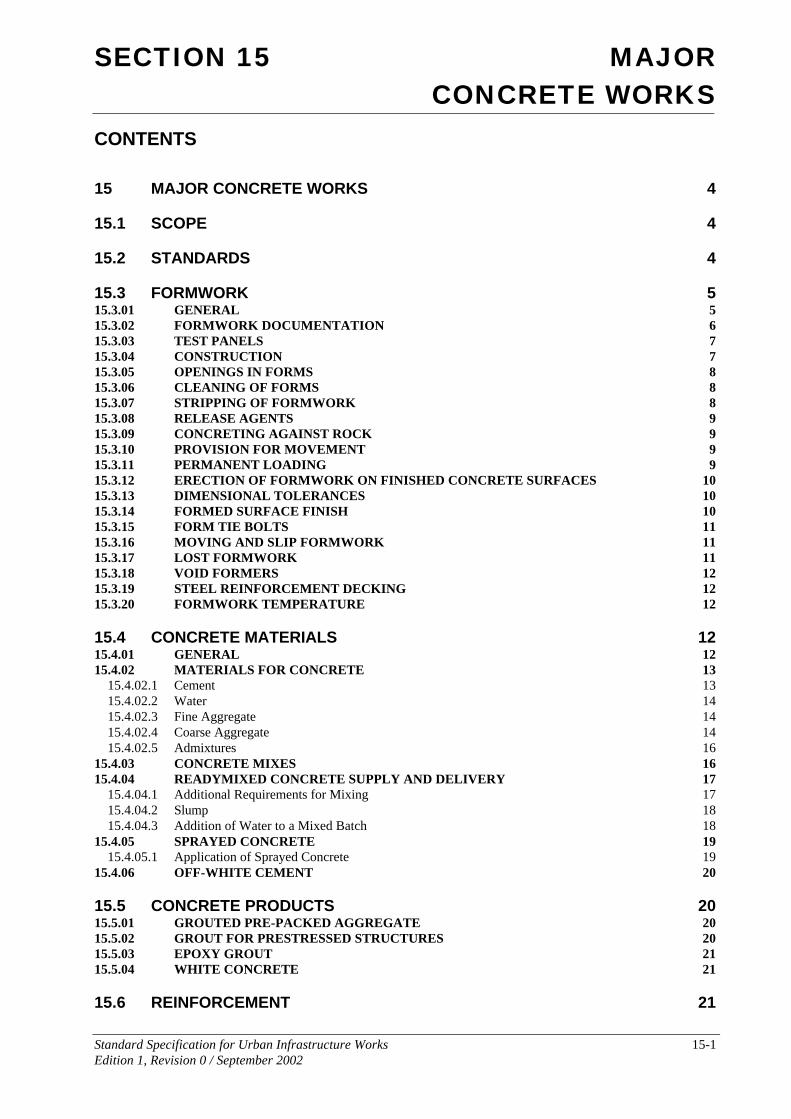
CONTENTS
15 MAJOR CONCRETE WORKS 4
15.1 SCOPE 4
15.2 STANDARDS 4
15.3 FORMWORK 5 15.3.01 GENERAL 5 15.3.02 FORMWORK DOCUMENTATION 6 15.3.03 TEST PANELS 7 15.3.04 CONSTRUCTION 7 15.3.05 OPENINGS IN FORMS 8 15.3.06 CLEANING OF FORMS 8 15.3.07 STRIPPING OF FORMWORK 8 15.3.08 RELEASE AGENTS 9 15.3.09 CONCRETING AGAINST ROCK 9 15.3.10 PROVISION FOR MOVEMENT 9 15.3.11 PERMANENT LOADING 9 15.3.12 ERECTION OF FORMWORK ON FINISHED CONCRETE SURFACES 10 15.3.13 DIMENSIONAL TOLERANCES 10 15.3.14 FORMED SURFACE FINISH 10 15.3.15 FORM TIE BOLTS 11 15.3.16 MOVING AND SLIP FORMWORK 11 15.3.17 LOST FORMWORK 11 15.3.18 VOID FORMERS 12 15.3.19 STEEL REINFORCEMENT DECKING 12 15.3.20 FORMWORK TEMPERATURE 12
15.4 CONCRETE MATERIALS 12 15.4.01 GENERAL 12 15.4.02 MATERIALS FOR CONCRETE 13
15.4.02.1 Cement 13 15.4.02.2 Water 14 15.4.02.3 Fine Aggregate 14 15.4.02.4 Coarse Aggregate 14 15.4.02.5 Admixtures 16
15.4.03 CONCRETE MIXES 16 15.4.04 READYMIXED CONCRETE SUPPLY AND DELIVERY 17
15.4.04.1 Additional Requirements for Mixing 17 15.4.04.2 Slump 18 15.4.04.3 Addition of Water to a Mixed Batch 18
15.4.05 SPRAYED CONCRETE 19 15.4.05.1 Application of Sprayed Concrete 19
15.4.06 OFF-WHITE CEMENT 20
15.5 CONCRETE PRODUCTS 20 15.5.01 GROUTED PRE-PACKED AGGREGATE 20 15.5.02 GROUT FOR PRESTRESSED STRUCTURES 20 15.5.03 EPOXY GROUT 21 15.5.04 WHITE CONCRETE 21
15.6 REINFORCEMENT 21
SECTION 15 MAJOR CONCRETE WORKS
Standard Specification for Urban Infrastructure Works 15-2 Edition 1, Revision 0 / September 2002
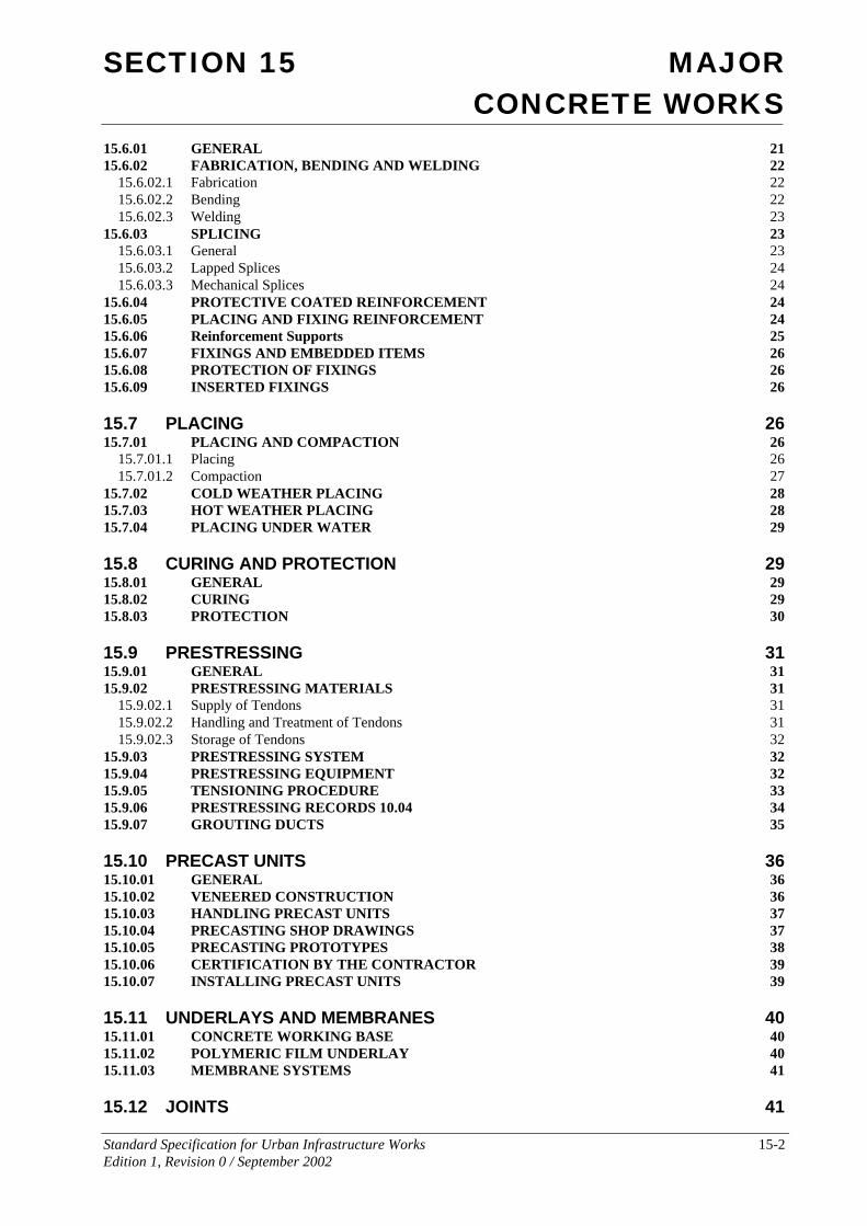
15.6.01 GENERAL 21 15.6.02 FABRICATION, BENDING AND WELDING 22
15.6.02.1 Fabrication 22 15.6.02.2 Bending 22 15.6.02.3 Welding 23
15.6.03 SPLICING 23 15.6.03.1 General 23 15.6.03.2 Lapped Splices 24 15.6.03.3 Mechanical Splices 24
15.6.04 PROTECTIVE COATED REINFORCEMENT 24 15.6.05 PLACING AND FIXING REINFORCEMENT 24 15.6.06 Reinforcement Supports 25 15.6.07 FIXINGS AND EMBEDDED ITEMS 26 15.6.08 PROTECTION OF FIXINGS 26 15.6.09 INSERTED FIXINGS 26
15.7 PLACING 26 15.7.01 PLACING AND COMPACTION 26
15.7.01.1 Placing 26 15.7.01.2 Compaction 27
15.7.02 COLD WEATHER PLACING 28 15.7.03 HOT WEATHER PLACING 28 15.7.04 PLACING UNDER WATER 29
15.8 CURING AND PROTECTION 29 15.8.01 GENERAL 29 15.8.02 CURING 29 15.8.03 PROTECTION 30
15.9 PRESTRESSING 31 15.9.01 GENERAL 31 15.9.02 PRESTRESSING MATERIALS 31
15.9.02.1 Supply of Tendons 31 15.9.02.2 Handling and Treatment of Tendons 31 15.9.02.3 Storage of Tendons 32
15.9.03 PRESTRESSING SYSTEM 32 15.9.04 PRESTRESSING EQUIPMENT 32 15.9.05 TENSIONING PROCEDURE 33 15.9.06 PRESTRESSING RECORDS 10.04 34 15.9.07 GROUTING DUCTS 35
15.10 PRECAST UNITS 36 15.10.01 GENERAL 36 15.10.02 VENEERED CONSTRUCTION 36 15.10.03 HANDLING PRECAST UNITS 37 15.10.04 PRECASTING SHOP DRAWINGS 37 15.10.05 PRECASTING PROTOTYPES 38 15.10.06 CERTIFICATION BY THE CONTRACTOR 39 15.10.07 INSTALLING PRECAST UNITS 39
15.11 UNDERLAYS AND MEMBRANES 40 15.11.01 CONCRETE WORKING BASE 40 15.11.02 POLYMERIC FILM UNDERLAY 40 15.11.03 MEMBRANE SYSTEMS 41
15.12 JOINTS 41
SECTION 15 MAJOR CONCRETE WORKS
Standard Specification for Urban Infrastructure Works 15-3 Edition 1, Revision 0 / September 2002
15.12.01 CONSTRUCTION JOINTS 41 15.12.02 MOVEMENT JOINTS 42
15.12.02.1 Vertical Expansion Joints 42 15.12.02.2 Barrier Contraction Joints 42 15.12.02.3 Barrier Expansion Joints 42
15.12.03 JOINTING MATERIALS 42 15.12.04 JOINT DOWELS 43 15.12.05 JOINT FILLING 43 15.12.06 WATERSTOPS 43
15.13 INTEGRAL FINISHES 43 15.13.01 TOLERANCE CLASSES FOR FINISHES AS LAID 43 15.13.02 FINISHES AS LAID 44 15.13.03 RUBBED AND FLOATED FINISHES 44 15.13.04 SURFACE TREATMENT 45 15.13.05 SURFACE MODIFIERS 45
15.14 SAMPLING AND TESTING 45 15.14.01 TESTING 46 15.14.02 STRENGTH OF CONCRETE 46 15.14.03 ADJUSTMENT FOR AGE OF SPECIMEN 47 15.14.04 SPECIMENS CUT FROM THE WORKS (CORES) 47 15.14.05 CONFORMANCE OF CONCRETE 48 15.14.06 FREQUENCY OF TESTING 48
15.15 MEASUREMENT AND PAYMENT 51
15.16 SCHEDULE OF HOLD POINTS 52
SECTION 15 MAJOR CONCRETE WORKS
Standard Specification for Urban Infrastructure Works 15-4 Edition 1, Revision 0 / September 2002
15 MAJOR CONCRETE WORKS
15.1 SCOPE The works covered by this Section of the Specification comprise the construction of major concrete elements and products not included in Section 6 of this Specification. It includes precast and prestressed concrete and reinforced concrete elements and products. Also covered is the formwork, reinforcement, jointing and finishing and associated activities relevant to the production of concrete elements and products.
15.2 STANDARDS Work carried out and testing performed under this Section of the Specification shall comply with the requirements of the following standards to the extent that they are relevant and not overridden by the Specification. It should be noted that this is not a comprehensive list, but serves as guidance only.
Australian Standards
AS 1012 Methods of Testing Concrete
AS 1141 Methods for Sampling and Testing Aggregates
AS 1214 Hot-dip Galvanised Coatings on Threaded Fasteners
AS 1289 Methods of Testing Soils for Engineering Purposes
AS 1302 Steel Reinforcing Bars for Concrete
AS 1303 Hard Drawn Steel Reinforcing Wire for Concrete
AS 1304 Welded Wire Reinforcing Fabric for Concrete
AS 1310 Steel Wire for Tendons in Prestressed Concrete
AS 1311 Steel Tendons for Prestressed Concrete - 7 Wire Stress relieved Strand for Tendons in Prestressed Concrete
AS 1313 Steel Tendons for Prestressed Concrete - Cold Worked High -tensile Alloy Steel Bars for Prestressed Concrete
AS 1314 Prestressing Anchorages (Metric Units)
AS 1349 Bourdon Tube Pressure and Vacuum Gauges
AS 1379 Specification and Supply of Concrete
AS 1397 Steel Sheet and Strip - Hot-dipped Zinc-coated or Aluminium/ zinc coated
AS 1478 Chemical Admixtures for Use in Concrete
AS 1554 Structural Steel Welding
AS 4680 Hot-dipped Galvanised Coatings on Ferrous Articles
AS 2072 Methods for the Sampling of Expanding Admixtures for Concrete, Mortar and Grout
AS 2073 Methods for the Testing of Expanding Admixtures for Concrete, Mortar and Grout
SECTION 15 MAJOR CONCRETE WORKS
Standard Specification for Urban Infrastructure Works 15-5 Edition 1, Revision 0 / September 2002
AS 2327 Composite Structures
AS 2349 Methods of Sampling Portland and Blended Cements
AS 2350 Methods of Testing Portland and Blended Cements
AS 2758 Aggregates and Rock for Engineering Purposes
AS 2870 Residential Slabs and Footings - Construction
AS 2876 Concrete Kerbs and Channels (Gutters) – Manually or Machine Placed
AS 3582 Supplementary Cementitious Materials for Use with Portland Cement Part 1 - Fly ash Part 2 - Slag - Ground Granulated Iron Blast-Furnace
AS 3583 Methods of Test for Supplementary Cementitious Materials for Use with Portland and Blended Cement
AS 3600 Concrete Structures
AS 3610 Formwork for Concrete
AS 3735 Concrete Structures for Retaining Liquids
AS 3799 Liquid Membrane - forming Curing Compounds for Concrete
AS 3850 Tilt-up Concrete and Precast Concrete Elements for use in Buildings
AS 3972 Portland and Blended Cements
AS 4100 Steel Structures
AS CA55 Code of Recommended Practice for the Design and Installation of Bituminous Fabric Roofing
Other Standards and Guidelines
ASTM C309 Liquid Membrane – Forming Compounds for Curing Concrete
Reference to the above Standards shall be deemed to include reference to all parts of each standard and any supplementary volumes and shall be deemed to be the latest edition of the Standard.
Testing
A Testing Authority shall be employed by the Contractor to carry out all testing. The Authority shall hold a current NATA (National Association of Testing Authorities) Registration for the relevant tests, and a copy of results shall be forwarded to the Superintendent without delay.
The Contractor shall keep on site a copy of AS 3600, Concrete Structures Standard.
15.3 FORMWORK
15.3.01 GENERAL
The materials, design, fabrication and stripping of formwork shall comply with the relevant requirements of AS3610 and this Specification.
SECTION 15 MAJOR CONCRETE WORKS
Standard Specification for Urban Infrastructure Works 15-6 Edition 1, Revision 0 / September 2002
Formwork shall be provided to produce hardened concrete to the lines, levels and shapes shown on the drawings or specified elsewhere. It shall have adequate strength to carry all applied loads, including the pressure of fresh concrete, vibration loads, weight of workers and equipment, without loss of shape. Forms shall be mortar tight and designed to allow removal without risk of damage to the completed structure. Joints in the formwork shall be perpendicular to the main axis of the shape of the concrete.
Design of formwork for high sections shall be such that it shall not be necessary to drop concrete freely from a height greater than 1.6 metres or to move concrete along the formwork after deposition.
Material used for formwork shall be sound and suitable for the purpose intended and surface finish specified.
Provision shall be made for the accurate location and firm support of fittings, bolts, anchorages and formers of holes as shown on the drawings. Temporary fittings used for the support of the formwork shall be arranged to permit removal without damage to the concrete. The use of wires and or bolts extending to the surface of the concrete shall not be permitted except where shown on the Drawings.
Forms for edges of concrete shall be filleted and for re-entrant angles chamfered as shown on the Drawings.
15.3.02 FORMWORK DOCUMENTATION
The Contractor shall submit formwork documentation prior to erection of formwork. Documentation shall be in accordance with AS 3610 Clause 4.7 together with details of proposed form linings, form coatings, release agents and, where applicable, re-use of formwork. Where particular requirements, in accordance with AS 3610 Clause 2.3, are specified on the drawings or in the Specification, those requirements shall also be indicated on the formwork documentation.
For multi-storey work, bridgework or for suspended formwork, the Contractor shall provide calculations and an Engineer’s Certification to show that acceptable design criteria will not be exceeded where:
• formwork procedures or loadings differ from the information included in the Project Documentation;
• Project Documentation does not include formwork shoring or stripping procedures or allowable loadings from stacked materials;
• props above a floor do not coincide with the props below.
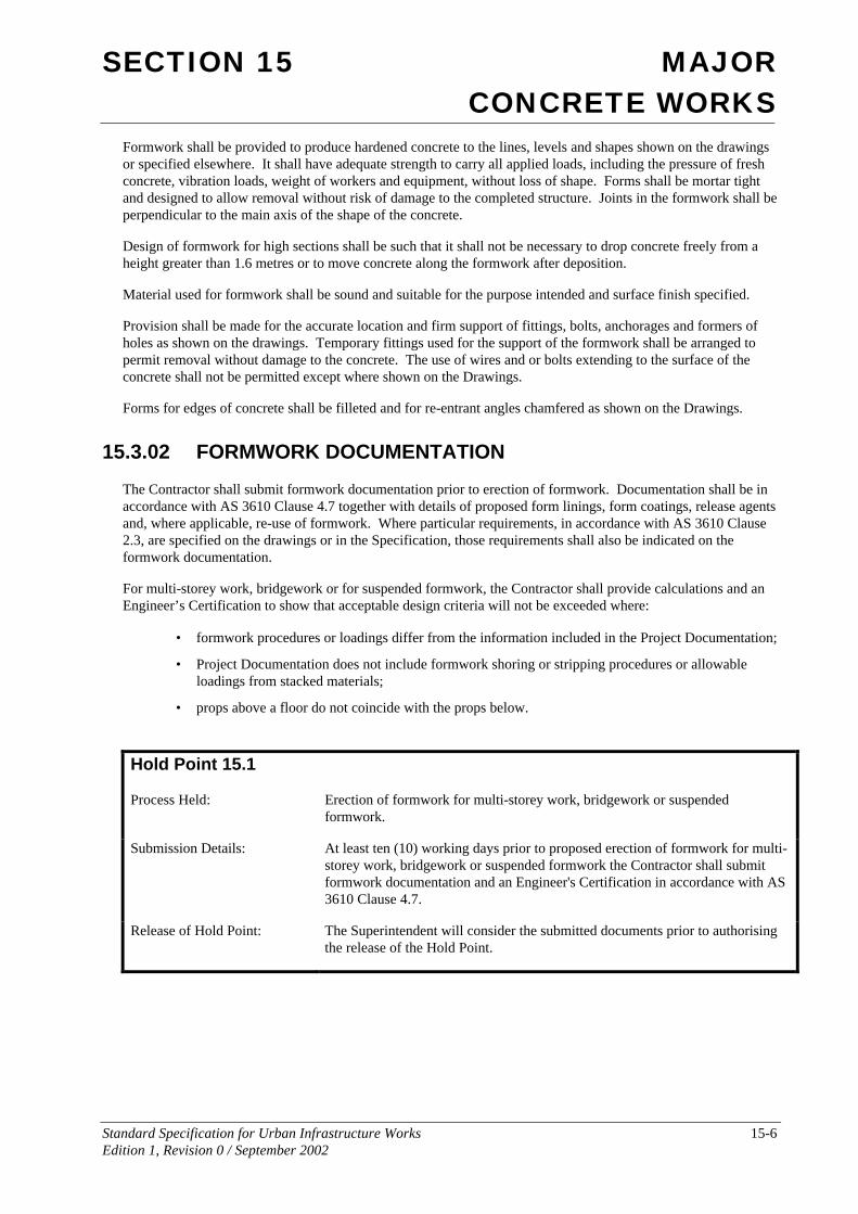
Hold Point 15.1
Process Held: Erection of formwork for multi-storey work, bridgework or suspended formwork.
Submission Details: At least ten (10) working days prior to proposed erection of formwork for multi-storey work, bridgework or suspended formwork the Contractor shall submit formwork documentation and an Engineer's Certification in accordance with AS 3610 Clause 4.7.
Release of Hold Point: The Superintendent will consider the submitted documents prior to authorising the release of the Hold Point.
SECTION 15 MAJOR CONCRETE WORKS
Standard Specification for Urban Infrastructure Works 15-7 Edition 1, Revision 0 / September 2002
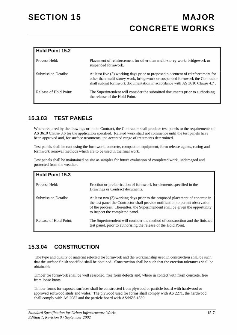
Hold Point 15.2
Process Held: Placement of reinforcement for other than multi-storey work, bridgework or suspended formwork.
Submission Details: At least five (5) working days prior to proposed placement of reinforcement for other than multi-storey work, bridgework or suspended formwork the Contractor shall submit formwork documentation in accordance with AS 3610 Clause 4.7 .
Release of Hold Point: The Superintendent will consider the submitted documents prior to authorising the release of the Hold Point.
15.3.03 TEST PANELS
Where required by the drawings or in the Contract, the Contractor shall produce test panels to the requirements of AS 3610 Clause 3.6 for the application specified. Related work shall not commence until the test panels have been approved and, for surface treatments, the accepted range of treatments determined.
Test panels shall be cast using the formwork, concrete, compaction equipment, form release agents, curing and formwork removal methods which are to be used in the final work.
Test panels shall be maintained on site as samples for future evaluation of completed work, undamaged and protected from the weather.
Hold Point 15.3
Process Held: Erection or prefabrication of formwork for elements specified in the Drawings or Contract documents.
Submission Details: At least two (2) working days prior to the proposed placement of concrete in the test panel the Contractor shall provide notification to permit observation of the process. Thereafter, the Superintendent shall be given the opportunity to inspect the completed panel.
Release of Hold Point: The Superintendent will consider the method of construction and the finished test panel, prior to authorising the release of the Hold Point.
15.3.04 CONSTRUCTION
The type and quality of material selected for formwork and the workmanship used in construction shall be such that the surface finish specified shall be obtained. Construction shall be such that the erection tolerances shall be obtainable.
Timber for formwork shall be well seasoned, free from defects and, where in contact with fresh concrete, free from loose knots.
Timber forms for exposed surfaces shall be constructed from plywood or particle board with hardwood or approved softwood studs and wales. The plywood used for forms shall comply with AS 2271, the hardwood shall comply with AS 2082 and the particle board with AS/NZS 1859.
SECTION 15 MAJOR CONCRETE WORKS
Standard Specification for Urban Infrastructure Works 15-8 Edition 1, Revision 0 / September 2002
Forms for all surfaces which will be completely enclosed or permanently hidden below the ground may be constructed from dressed or undressed timber, steel, plywood or particle board.
Mild steel form surfaces in contact with concrete shall have all bolt and rivet heads counter-sunk and all welds ground back to even and smooth surfaces.
15.3.05 OPENINGS IN FORMS
Form openings or removable panels shall be provided in vertical or near vertical forms where necessary for cleaning and inspection.
15.3.06 CLEANING OF FORMS
Forms shall be thoroughly cleaned, and free water, dust, debris, rust and other stains shall be removed from the forms and formed space, prior to the application of the form release agent, and again prior to placing of concrete.
15.3.07 STRIPPING OF FORMWORK
Formwork shall be stripped in accordance with AS 3600 Clause 19.6.2, where those requirements are more stringent than the relevant requirements of AS 3610, or in accordance with the requirements of the Contract Documentation and this Specification. For prestressed concrete members, supporting formwork shall not be stripped until sufficient prestress has been applied to the member.
For multi-storey construction, details of the reshoring program where required shall be submitted to the Superintendent.
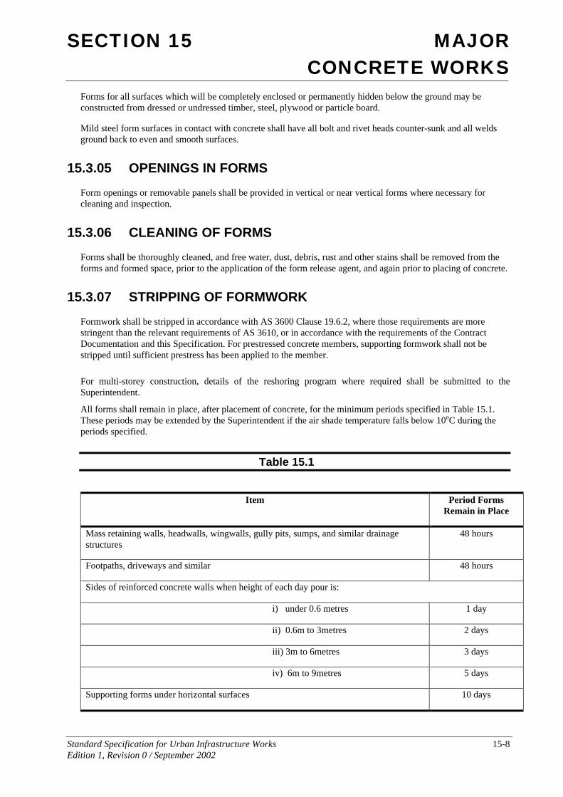
All forms shall remain in place, after placement of concrete, for the minimum periods specified in Table 15.1. These periods may be extended by the Superintendent if the air shade temperature falls below 10oC during the periods specified.
Table 15.1
Item Period Forms Remain in Place
Mass retaining walls, headwalls, wingwalls, gully pits, sumps, and similar drainage structures
48 hours
Footpaths, driveways and similar 48 hours
Sides of reinforced concrete walls when height of each day pour is:
i) under 0.6 metres 1 day
ii) 0.6m to 3metres 2 days
iii) 3m to 6metres 3 days
iv) 6m to 9metres 5 days
Supporting forms under horizontal surfaces 10 days
SECTION 15 MAJOR CONCRETE WORKS
Standard Specification for Urban Infrastructure Works 15-9 Edition 1, Revision 0 / September 2002
To permit the satisfactory finishing of barriers, forms shall be removed in not less than 12 hours nor more than 48 hours after placing concrete, depending upon weather conditions.
Care shall be taken in removing forms so that the concrete will not be cracked, chipped or otherwise damaged. The use of crowbars or other levering devices exerting pressure on the fresh concrete to loosen the forms will not be permitted.
Hole formers such as pipes and bars shall be removed as soon as the concrete has hardened sufficiently for this to be done without damage to the concrete.
15.3.08 RELEASE AGENTS
Prior to placing reinforcement a release agent shall be applied to the interior surfaces of the formwork to ensure non-adhesion of the mortar, except where the concrete is to receive an applied finish for which there is no compatible release agent.
Commercial quality form oil or grease will be acceptable, provided that the oil or grease used on forms against surfaces to be exposed shall not stain or discolour the concrete surface. The coating shall be uniformly spread in a thin film and any surplus shall be removed prior to placing concrete. In the case of unlined timber forms, the timber shall be thoroughly wetted before oiling. Forms shall be treated before placing reinforcement to ensure that the form release agent will not contaminate the surface of the reinforcing steel or construction joints.
Release agents shall be chosen such that they are compatible with the form lining or facing, the plastic concrete and all its constituents and subsequent concrete surface treatments.
Formwork hardware shall be treated with a form release agent and so arranged such that it may be removed from the concrete without excessive jarring or hammering.
No part of the reinforcement or construction joints shall be coated with the release agent. Where necessary the reinforcement and construction joint surfaces shall be cleaned to remove all traces of release agent.
15.3.09 CONCRETING AGAINST ROCK
Subject to the approval of the Superintendent, concrete may be poured against rock faces, provided that the cover to the reinforcement on the rock face is increased by a minimum of 25 mm. Before any concrete is poured against a rock face all leakage and percolation of water which could cause damage to the wet concrete shall be effectively sealed. Concrete shall not be poured against horizontal or inclined rubble, fill or earth surfaces in lieu of formwork, unless approved by the Superintendent.
15.3.10 PROVISION FOR MOVEMENT
All formwork and falsework shall be designed to account for dimensional changes, deflections and/or cambers as specified in the Contract, drawings or by the Superintendent.
These variables may result from the application of prestressing forces, applied loads, temperature changes, concrete creep and shrinkage and other such factors.
15.3.11 PERMANENT LOADING
Permanent loads, including masonry walls and the like, shall not be placed on the concrete structure while it is still supported by falsework. Unless otherwise specified, superimposed loads to any part of the structure shall not be applied until the design concrete strength stated in the Drawings has been achieved.
SECTION 15 MAJOR CONCRETE WORKS
Standard Specification for Urban Infrastructure Works 15-10 Edition 1, Revision 0 / September 2002
15.3.12 ERECTION OF FORMWORK ON FINISHED CONCRETE SURFACES
Formwork shall not be erected on finished concrete surfaces until the surfaces have attained sufficient strength to support the formwork without damage, and not before three (3) days after placement of the concrete. Suitable protective materials shall be placed between formwork bases and the finished concrete surfaces.
15.3.13 DIMENSIONAL TOLERANCES
Formwork and falsework shall be so designed and constructed that the concrete produced from the forms and construction joints and formwork lines where nominated in the project documentation, shall conform to the tolerances as indicated in AS 3610 Clause 3.4 and to AS 3600 Clause 19.5 or as otherwise permitted by the Contract. The sum of deviations, including in particular the following:
(i) its deflection under loads and other effects, plus
(ii) the falsework settlement, including foundation settlement, plus
(iii) its initial accuracy in position, will not exceed the deviations from correct position permitted by the Contract.
Tilt-up panels shall conform to the requirements of AS 3850.2 Clause 3.7.7.
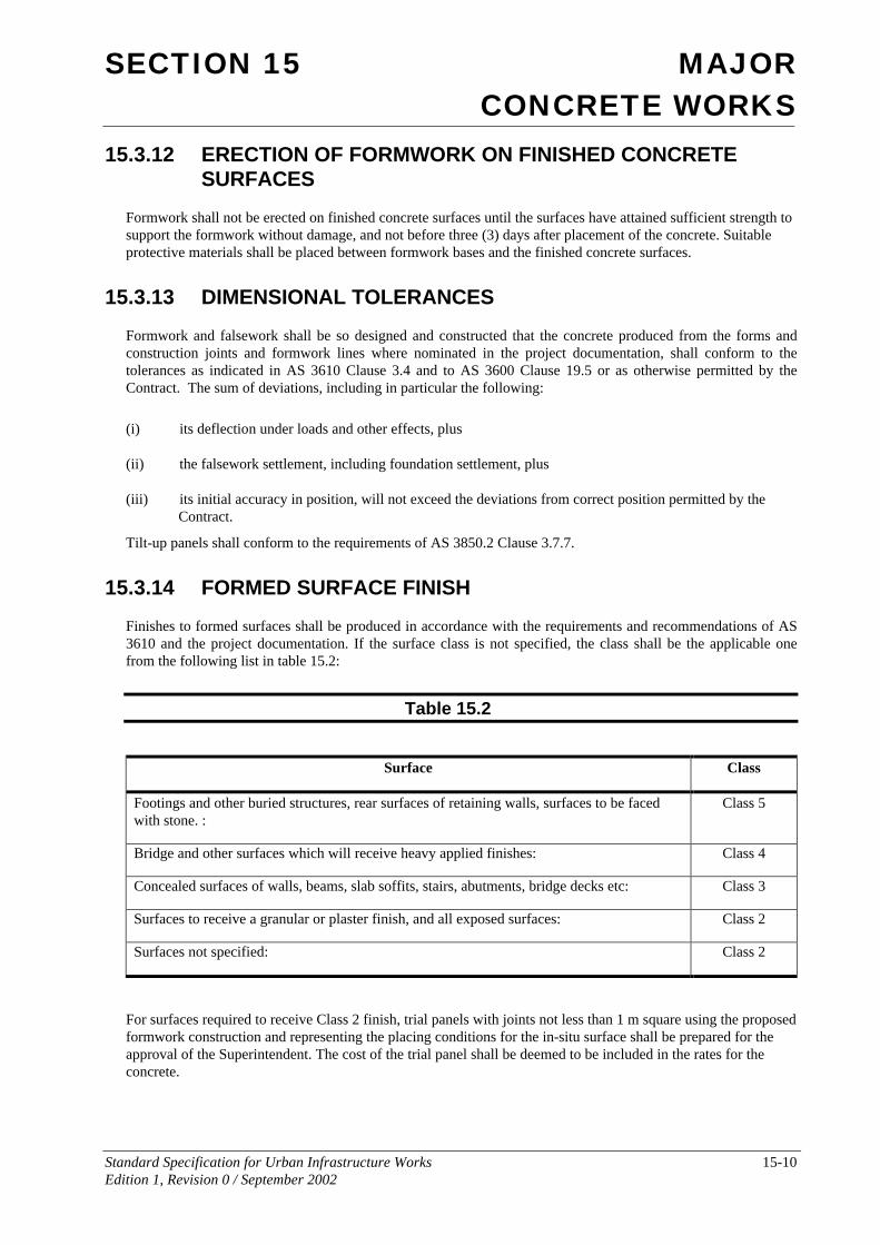
15.3.14 FORMED SURFACE FINISH
Finishes to formed surfaces shall be produced in accordance with the requirements and recommendations of AS 3610 and the project documentation. If the surface class is not specified, the class shall be the applicable one from the following list in table 15.2:
Table 15.2
Surface Class
Footings and other buried structures, rear surfaces of retaining walls, surfaces to be faced with stone. :
Class 5
Bridge and other surfaces which will receive heavy applied finishes: Class 4
Concealed surfaces of walls, beams, slab soffits, stairs, abutments, bridge decks etc: Class 3
Surfaces to receive a granular or plaster finish, and all exposed surfaces: Class 2
Surfaces not specified: Class 2
For surfaces required to receive Class 2 finish, trial panels with joints not less than 1 m square using the proposed formwork construction and representing the placing conditions for the in-situ surface shall be prepared for the approval of the Superintendent. The cost of the trial panel shall be deemed to be included in the rates for the concrete.
SECTION 15 MAJOR CONCRETE WORKS
Standard Specification for Urban Infrastructure Works 15-11 Edition 1, Revision 0 / September 2002
For concrete surface classes 1, 2 or 3, the formwork shall be set out to give regular arrangement of panels, joints, bolt holes and other visible elements of the formed surface. All corners and angles shall have 25 mm chamfers and bevels set at 45º to the surface face.
Formwork for exposed surfaces shall be made from panels having uniform widths of not less than 1m and uniform lengths of not less than 2m, except where the dimensions of the member formed are less than the specified panel dimensions. Plywood panels shall be placed with the grain of the outer plies perpendicular to the studding or joists. Where form panels are attached directly to the studding or joists the panel shall be not less than 15mm thick. Form panels less than 15mm thick, otherwise conforming to these requirements may be used with a continuous backing of dressed material of 20mm minimum thickness. All form panels shall be placed in a neat, symmetrical pattern.
Where colour control is specified, form linings shall not be inferior to those described as "suitable" in AS 3610 Supplement 2, Table C5.4. 1.
If the Superintendent considers that the formed surface finish of the completed work does not comply with the Contract, an evaluation of the finish in accordance with AS 3610 Clause 5.6 may be requested. This evaluation shall be carried out by the Contractor in the presence of the Superintendent.
Repairs to Class 1 surfaces shall not be permitted. Repair of defective formed surfaces of lesser class shall be performed in accordance with AS 3610 Clause 5.6.5. The method of repair, the materials and proposals for curing of repaired areas shall be submitted to the Superintendent prior to commencing repairs.
Concrete spacer blocks, where they form part of the exposed surface of the concrete, shall be identical in colour and strength to the finished concrete.
15.3.15 FORM TIE BOLTS
Tie bolts shall be positioned such that those left in the concrete do not project into the concrete cover.
Tie bolts shall be removed without causing damage to the concrete surface. Where the concrete surface is to be later treated, tie bolt cores shall be loosened but left in place until after the surface treatment is applied.
Filling of tie bolt holes shall be with a material which matches the surface colour. Filling shall be recessed 5 mm below the concrete surface to give a neat appearance.
15.3.16 MOVING AND SLIP FORMWORK
Slip formwork or moving formwork shall consist of suitable equipment, constructed and operated by personnel experienced in its use. The Contractor shall show on formwork drawings the method of lifting the forms during construction and the average rate of movement. Formwork proposals shall demonstrate that the proposed average rate of movement will permit the production of concrete of the specified quality and surface.
Slip formwork shall provide a hanging scaffold below the moving formwork on all faces, from which surface treatment and inspection may be carried out.
15.3.17 LOST FORMWORK
Permanent or lost formwork, if required, shall not contain chlorides, and shall not impair the structural performance of the concrete members.
Lost formwork shall not corrode, perish or decay such that the durability or serviceability of the concrete is compromised.
Unless specified, lost formwork shall not be permitted without the approval of the Superintendent.
SECTION 15 MAJOR CONCRETE WORKS
Standard Specification for Urban Infrastructure Works 15-12 Edition 1, Revision 0 / September 2002
15.3.18 VOID FORMERS
Where shown on the drawings, suspended ground floor slabs and beams shall be cast on unwaxed cardboard or fibreboard void formers which are collapsible on absorption of moisture. Void formers shall be kept dry until use, placed on a firm level surface and covered with a waterproof membrane. Reinforcement shall be placed and concrete cast with minimum delay.
The Contractor shall supply certificates to confirm that the formers comply with the following requirements, under laboratory conditions, when placed on damp sand and loaded with a mass of wet concrete not less than the mass of the beams or slabs they are required to support:
• deflection during placing and compaction of the concrete is less than the span of the beam or slab divided by 1000;
• additional deflection between initial set and seven days does not exceed span/400;
• collapse and loss of load carrying capacity will occur not more than 48 hours after flooding with water, creating a void not less than 60% of the original depth of the void former.
Where void formers are specified for voided slab construction, void formers shall be galvanised steel or expanded polystyrene. Where galvanised steel void formers are specified, they shall have a wall thickness compatible with their proposed use and loading condition. Voids shall be sealed from ingress of water or grout and shall be effectively restrained from uplift under hydrostatic pressure.
15.3.19 STEEL REINFORCEMENT DECKING
Hot dipped zinc-coated sheet steel which acts as both permanent formwork and positive tensile reinforcing steel in one-way reinforced concrete slab construction, shall be to AS 1397, minimum G500-Z200.
Steel decking shall be provided with temporary propping while placing concrete, and for 28 days thereafter, where required by the manufacturer or specified.
15.3.20 FORMWORK TEMPERATURE
If it is likely that the ambient air temperature may fall to 5ºC or less during placement of concrete, the forms shall be covered for at least 12 hours prior to concreting and the enclosed space shall be heated so that the temperature of the form faces is not below 5ºC at the time of concrete placement.
If it is likely that the ambient air temperature may rise to more than 32ºC during placement of the concrete, the forms shall be adequately shaded or sprayed with water so as to prevent the temperature of the form faces rising above 35ºC.
15.4 CONCRETE MATERIALS
15.4.01 GENERAL
Unless otherwise identified in this Specification materials for concrete shall comply with AS 3600 Clause 19.1 and AS 1379.
Ready mixed concrete shall be produced by a manufacturing plant, which is:
(a) operating under a quality assurance system which satisfies the requirements of ISO 9002, or
(b) registered under the NSW Government Concrete Quality Assurance Scheme.
SECTION 15 MAJOR CONCRETE WORKS
Standard Specification for Urban Infrastructure Works 15-13 Edition 1, Revision 0 / September 2002
Suppliers of reinforcement materials and curing compounds shall have a quality assurance system in accordance with ISO 9002 which covers the supply of reinforcement material or the supply of curing compounds, as appropriate.
Hold Point 15.4
Process Held: Initial production of each Strength Grade
Submission Details: At least five (5) working days prior to concrete production the Contractor shall submit a statement verifying that the concrete, its constituent materials and curing compounds comply with specified requirements. The statement shall be supported by the Production Assessment Report from the previous month or test reports where Production Assessment has not been carried out.
Release of Hold Point: The Superintendent shall consider the submitted documents and may inspect test records prior to authorising the release of the Hold Point.
If production assessment is nominated on the drawings or in the Contract the Contractor shall register the project with the concrete supplier and obtain production assessment information in accordance with AS 1379. For concrete subject to project assessment, the Contractor shall produce monthly a Project Assessment Report for each strength grade, in a form similar to a Production Assessment Report.
Copies of the Contractor’s completed verification checklists, Production and Project Assessment Reports shall be forwarded on request.
15.4.02 MATERIALS FOR CONCRETE
15.4.02.1 Cement All Portland cement and Blended cement constituents shall be from a source included in the New South Wales Government Concrete Quality Assurance Scheme applicable to the period covered by the Contract.
Portland cement shall be Type SL Shrinkage Limited Cement and shall have an autoclave expansion as determined by ASTM Method C151, less than 0.8%.
Type GB General Purpose Blended Cement shall be Type GB General Purpose Blended Cement complying with AS 3972.
Supplementary cementitous materials (SCM) Fly Ash, Slag and Silica Fume shall comply with AS 3582 Parts 1, 2 and 3 respectively.
When submitting details of the nominated mix in accordance with Clause 15.4.01, the Contractor shall nominate the brand and source of the cement. On approval of the nominated mix by the Superintendent, the Contractor shall only use the nominated cement for the work.
Documentary or other acceptable evidence of the quality of the cement shall be furnished by the Contractor if required by the Superintendent.
If the Contractor proposes to use cement which has been stored for a period in excess of 3 months from the date of testing, a re-test shall be required at the Contractor's expense before the cement is used.
All cement shall be transported in watertight containers, and shall be protected from moisture until used. Caked or lumpy cement shall not be used.
SECTION 15 MAJOR CONCRETE WORKS
Standard Specification for Urban Infrastructure Works 15-14 Edition 1, Revision 0 / September 2002
15.4.02.2 Water Water shall be clean and free from injurious amounts of oils, acids, alkalis, organic materials harmful to concrete and to its reinforcement and neither salty nor brackish.
Water which is not potable for human beings shall not be used in reinforced concrete.
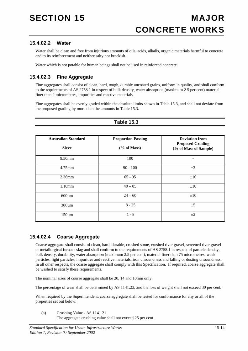
15.4.02.3 Fine Aggregate Fine aggregates shall consist of clean, hard, tough, durable uncoated grains, uniform in quality, and shall conform to the requirements of AS 2758.1 in respect of bulk density, water absorption (maximum 2.5 per cent) material finer than 2 micrometres, impurities and reactive materials.
Fine aggregates shall be evenly graded within the absolute limits shown in Table 15.3, and shall not deviate from the proposed grading by more than the amounts in Table 15.3.
Table 15.3
Australian Standard
Sieve
Proportion Passing
(% of Mass)
Deviation from Proposed Grading
(% of Mass of Sample)
9.50mm 100 -
4.75mm 90 - 100 ±3
2.36mm 65 - 95 ±10
1.18mm 40 – 85 ±10
600µm 24 – 60 ±10
300µm 8 - 25 ±5
150µm 1 - 8 ±2
15.4.02.4 Coarse Aggregate Coarse aggregate shall consist of clean, hard, durable, crushed stone, crushed river gravel, screened river gravel or metallurgical furnace slag and shall conform to the requirements of AS 2758.1 in respect of particle density, bulk density, durability, water absorption (maximum 2.5 per cent), material finer than 75 micrometres, weak particles, light particles, impurities and reactive materials, iron unsoundness and falling or dusting unsoundness. In all other respects, the coarse aggregate shall comply with this Specification. If required, coarse aggregate shall be washed to satisfy these requirements.
The nominal sizes of course aggregate shall be 20, 14 and 10mm only.
The percentage of wear shall be determined by AS 1141.23, and the loss of weight shall not exceed 30 per cent.
When required by the Superintendent, coarse aggregate shall be tested for conformance for any or all of the properties set out below:
(a) Crushing Value - AS 1141.21 The aggregate crushing value shall not exceed 25 per cent.
SECTION 15 MAJOR CONCRETE WORKS
Standard Specification for Urban Infrastructure Works 15-15 Edition 1, Revision 0 / September 2002
(b) Soundness - AS 1141.24 The loss of mass when tested with sodium sulphate shall not exceed 12 per cent.
(c) Particle Shape - AS 1141.14 The proportion of mis-shapen particles (2:1 ratio) shall not exceed 35 per cent.
(d) Wet strength and wet/dry strength variation tests shall be used for aggregate durability assessment in accordance with AS 2758.1 with duplicate testing being carried out in accordance with AS 1141.22.
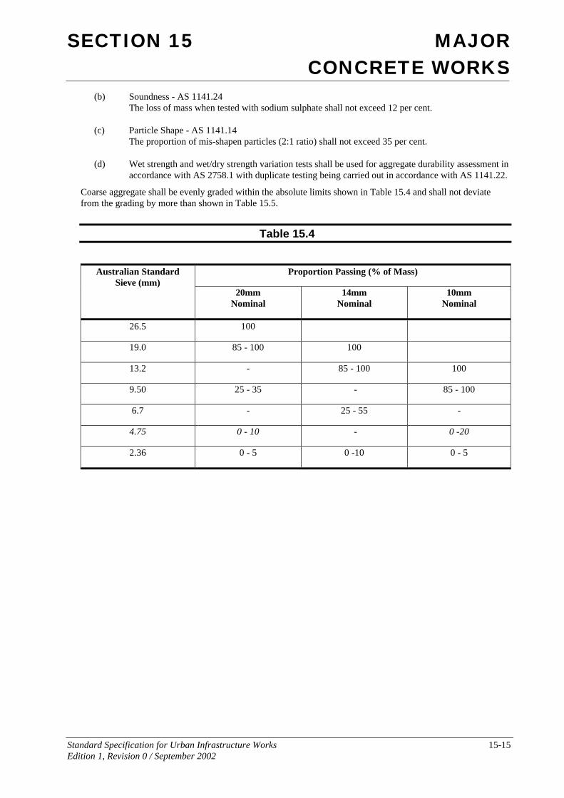
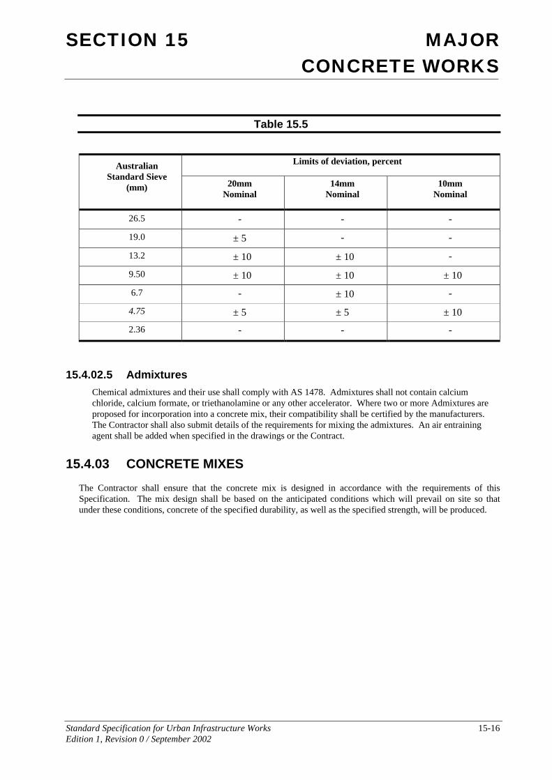
Coarse aggregate shall be evenly graded within the absolute limits shown in Table 15.4 and shall not deviate from the grading by more than shown in Table 15.5.
Table 15.4
Proportion Passing (% of Mass) Australian Standard Sieve (mm)
20mm Nominal
14mm Nominal
10mm Nominal
26.5 100
19.0 85 - 100 100
13.2 - 85 - 100 100
9.50 25 - 35 - 85 - 100
6.7 - 25 - 55 -
4.75 0 - 10 - 0 -20
2.36 0 - 5 0 -10 0 - 5
SECTION 15 MAJOR CONCRETE WORKS
Standard Specification for Urban Infrastructure Works 15-16 Edition 1, Revision 0 / September 2002
Table 15.5
Limits of deviation, percent Australian Standard Sieve
(mm) 20mm Nominal
14mm Nominal
10mm Nominal
26.5 - - -
19.0 ± 5 - -
13.2 ± 10 ± 10 -
9.50 ± 10 ± 10 ± 10
6.7 - ± 10 -
4.75 ± 5 ± 5 ± 10
2.36 - - -
15.4.02.5 Admixtures Chemical admixtures and their use shall comply with AS 1478. Admixtures shall not contain calcium chloride, calcium formate, or triethanolamine or any other accelerator. Where two or more Admixtures are proposed for incorporation into a concrete mix, their compatibility shall be certified by the manufacturers. The Contractor shall also submit details of the requirements for mixing the admixtures. An air entraining agent shall be added when specified in the drawings or the Contract.
15.4.03 CONCRETE MIXES
The Contractor shall ensure that the concrete mix is designed in accordance with the requirements of this Specification. The mix design shall be based on the anticipated conditions which will prevail on site so that under these conditions, concrete of the specified durability, as well as the specified strength, will be produced.
SECTION 15 MAJOR CONCRETE WORKS
Standard Specification for Urban Infrastructure Works 15-17 Edition 1, Revision 0 / September 2002
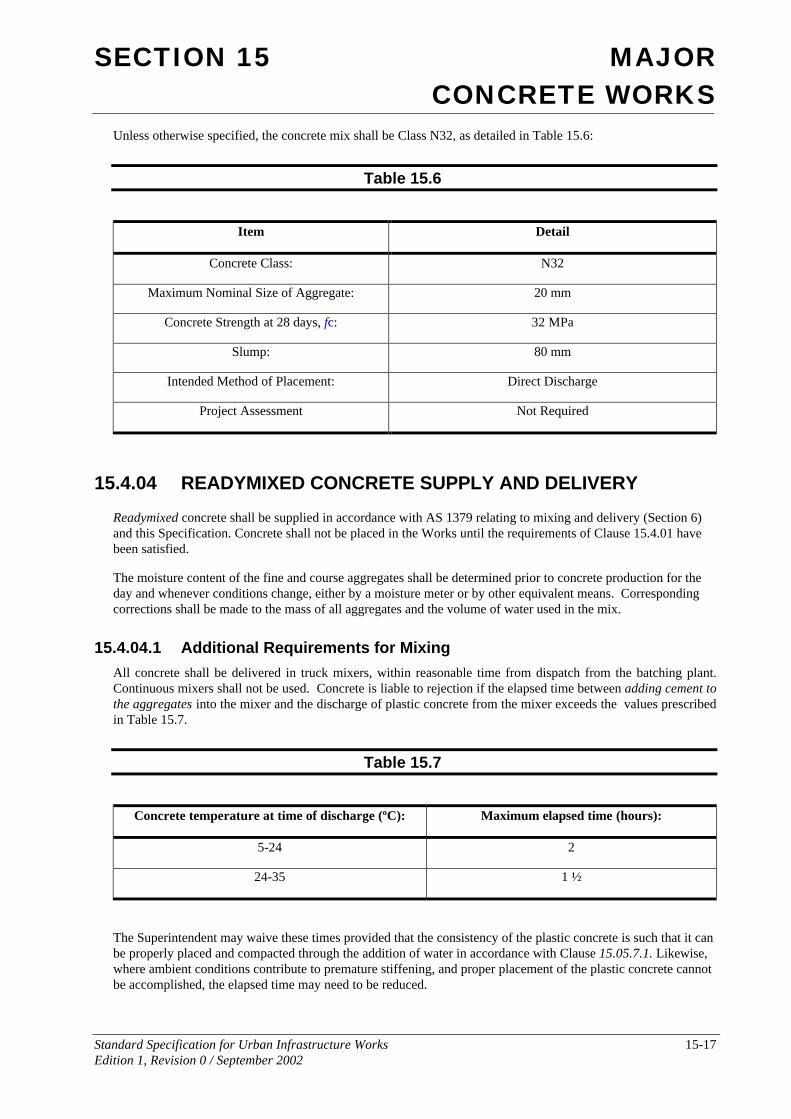
Unless otherwise specified, the concrete mix shall be Class N32, as detailed in Table 15.6:
Table 15.6
Item Detail
Concrete Class: N32
Maximum Nominal Size of Aggregate: 20 mm
Concrete Strength at 28 days, fc: 32 MPa
Slump: 80 mm
Intended Method of Placement: Direct Discharge
Project Assessment Not Required
15.4.04 READYMIXED CONCRETE SUPPLY AND DELIVERY
Readymixed concrete shall be supplied in accordance with AS 1379 relating to mixing and delivery (Section 6) and this Specification. Concrete shall not be placed in the Works until the requirements of Clause 15.4.01 have been satisfied.
The moisture content of the fine and course aggregates shall be determined prior to concrete production for the day and whenever conditions change, either by a moisture meter or by other equivalent means. Corresponding corrections shall be made to the mass of all aggregates and the volume of water used in the mix.
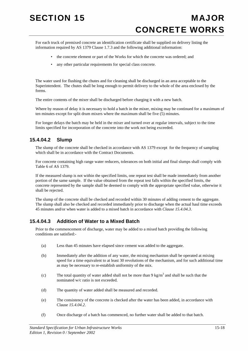
15.4.04.1 Additional Requirements for Mixing All concrete shall be delivered in truck mixers, within reasonable time from dispatch from the batching plant. Continuous mixers shall not be used. Concrete is liable to rejection if the elapsed time between adding cement to the aggregates into the mixer and the discharge of plastic concrete from the mixer exceeds the values prescribed in Table 15.7.
Table 15.7
Concrete temperature at time of discharge (ºC): Maximum elapsed time (hours):
5-24 2
24-35 1 ½
The Superintendent may waive these times provided that the consistency of the plastic concrete is such that it can be properly placed and compacted through the addition of water in accordance with Clause 15.05.7.1. Likewise, where ambient conditions contribute to premature stiffening, and proper placement of the plastic concrete cannot be accomplished, the elapsed time may need to be reduced.
SECTION 15 MAJOR CONCRETE WORKS
Standard Specification for Urban Infrastructure Works 15-18 Edition 1, Revision 0 / September 2002
For each truck of premixed concrete an identification certificate shall be supplied on delivery listing the information required by AS 1379 Clause 1.7.3 and the following additional information:
• the concrete element or part of the Works for which the concrete was ordered; and
• any other particular requirements for special class concrete.
The water used for flushing the chutes and for cleaning shall be discharged in an area acceptable to the Superintendent. The chutes shall be long enough to permit delivery to the whole of the area enclosed by the forms.
The entire contents of the mixer shall be discharged before charging it with a new batch.
Where by reason of delay it is necessary to hold a batch in the mixer, mixing may be continued for a maximum of ten minutes except for split drum mixers where the maximum shall be five (5) minutes.
For longer delays the batch may be held in the mixer and turned over at regular intervals, subject to the time limits specified for incorporation of the concrete into the work not being exceeded.
15.4.04.2 Slump The slump of the concrete shall be checked in accordance with AS 1379 except for the frequency of sampling which shall be in accordance with the Contract Documents.
For concrete containing high range water reducers, tolerances on both initial and final slumps shall comply with Table 6 of AS 1379.
If the measured slump is not within the specified limits, one repeat test shall be made immediately from another portion of the same sample. If the value obtained from the repeat test falls within the specified limits, the concrete represented by the sample shall be deemed to comply with the appropriate specified value, otherwise it shall be rejected.
The slump of the concrete shall be checked and recorded within 30 minutes of adding cement to the aggregate. The slump shall also be checked and recorded immediately prior to discharge when the actual haul time exceeds 45 minutes and/or when water is added to a mixed batch in accordance with Clause 15.4.04.3.
15.4.04.3 Addition of Water to a Mixed Batch Prior to the commencement of discharge, water may be added to a mixed batch providing the following conditions are satisfied:-
(a) Less than 45 minutes have elapsed since cement was added to the aggregate.
(b) Immediately after the addition of any water, the mixing mechanism shall be operated at mixing speed for a time equivalent to at least 30 revolutions of the mechanism, and for such additional time as may be necessary to re-establish uniformity of the mix.
(c) The total quantity of water added shall not be more than 9 kg/m3 and shall be such that the nominated w/c ratio is not exceeded.
(d) The quantity of water added shall be measured and recorded.
(e) The consistency of the concrete is checked after the water has been added, in accordance with Clause 15.4.04.2.
(f) Once discharge of a batch has commenced, no further water shall be added to that batch.
SECTION 15 MAJOR CONCRETE WORKS
Standard Specification for Urban Infrastructure Works 15-19 Edition 1, Revision 0 / September 2002
15.4.05 SPRAYED CONCRETE
Sprayed concrete is concrete pneumatically applied at high velocity on to a surface. Application may be either a wet or dry process. A sound homogeneous product shall be provided with surface finish reasonably uniform in texture and free from blemishes.
The minimum depth of sprayed concrete to be applied shall be 75mm.
Sprayed concrete lining in open drains shall be coloured to match the adjoining rock colour.
Sprayed concrete shall have a minimum cement content of 380 kg/m3 as discharged from the nozzle and shall have a minimum compressive strength of 25 MPa at 28 days when tested by means of 75mm diameter cores taken from in-place sprayed concrete.
Cores shall be secured, accepted, cured, capped and tested in accordance with AS 1012.14. The Contractor shall provide equipment and facilities for the taking of cores from the work. The Contractor shall arrange for a laboratory with appropriate NATA registration for the curing and testing of the cores. Copies of test results shall be forwarded to the Superintendent.
The cost of all work and material required in the taking, handling, delivery and testing of cores shall be borne by the Contractor.
At least ten (10) working days prior to applying any sprayed concrete the Contractor shall submit to the Superintendent details of the proposed procedures, plant, materials and mix proportions. Materials shall comply with AS 3600.
Hold Point 15.5
Process Held: Sprayed Concrete.
Submission Details: At least ten (10) working days prior to the proposed sprayed concrete construction the Contractor shall submit details of proposed procedures, plant, materials and mix proportions.
Release of Hold Point: The Superintendent will consider the submitted documents prior to authorising the release of the Hold Point.
15.4.05.1 Application of Sprayed Concrete
Application shall begin at the bottom of the area being sprayed and shall be built up making several passes of the nozzle over the working area. The nozzle shall be held so that the stream of material shall impinge as nearly as possible perpendicular to the surface being coated. The velocity of discharge from the nozzle, the distance of the nozzle from the surface and the amount of water in the mix shall be regulated so as to produce a dense coating with minimum rebound of the material and no sagging. Rebound material shall be removed after the initial set by air jet or other suitable means from the surface as work proceeds and disposed of.
Spraying shall be discontinued if wind causes separation of the nozzle stream.
Concrete shall not be sprayed in air temperatures less than 5oC.
Construction joints shall be kept to a minimum. A joint shall be formed by placing or trimming the sprayed concrete to an angle between 30o and 45o to the sprayed concrete surface. The joint edge shall be cleaned and wetted by air-water jet before recommencing concrete spraying.
SECTION 15 MAJOR CONCRETE WORKS
Standard Specification for Urban Infrastructure Works 15-20 Edition 1, Revision 0 / September 2002
When spraying around reinforcement, concrete is to be sprayed behind the reinforcement before concrete is allowed to accumulate on the face of the reinforcement.
Adjoining surfaces not requiring sprayed concrete shall be protected from splash and spray rebound. Splash or rebound material on these adjoining surfaces shall be removed by air-water jet or other suitable means as work proceeds.
Curing shall commence within one hour of the application of sprayed concrete and may be by water or by colourless wax emulsion curing compound complying with AS 3799 and applied in accordance with manufacturer’s specifications.
In water curing, the surface of the sprayed concrete shall be kept continuously wet for at least seven days.
15.4.06 OFF-WHITE CEMENT
Off-white cement shall be Portland Cement complying with AS 3972, shall be of one approved brand throughout and shall be carefully controlled to ensure that surface area and tricalcium aluminate content are maintained within agreed limits. The tricalcium aluminate content shall be less than 12% and the surface area shall be not greater than 450 m2/kg. The Brightness Index of the cement, which measures a standard magnesium carbonate block as 100 and black as zero, shall vary by no more than 2 from an agreed average value.
15.5 CONCRETE PRODUCTS
15.5.01 GROUTED PRE-PACKED AGGREGATE
Concrete made by grout intrusion into pre-packed aggregate shall be used only if specified. Details including aggregate grading, grout materials and proportions and proposed grouting methods shall be submitted to the Superintendent.
15.5.02 GROUT FOR PRESTRESSED STRUCTURES
Grout shall comply with AS 3600 Clause 19.1.11. It shall have a maximum water/ cement ratio of 0.45 (by mass) and a minimum compressive strength (75mm cube) of 30 MPa at twenty eight days.
Grout shall have the consistency appropriate to the application and shall have a maximum shrinkage of 1% by volume after 24 hours.
For buildings only:
Grout for prestressing ducts shall consist of accurately weighed portions of Type GP Portland Cement and water. The grout shall not include any sand, nor admixtures containing chlorides, nitrates, sulphides or sulphites. Portland Cement shall be free from calcium chloride and less than one month old from the date of manufacture.
For other structures:
Grout for prestressing ducts shall consist of accurately weighed portions of Type GP Portland Cement and water, with a water/cement ratio of 0.45. Portland Cement shall be free from calcium chloride and less than one month old from the date of manufacture. An additive shall be added to the mix in accordance with the manufacturer's recommendations to stop the settlement of grout such as METHOCEL Type K15MS or an approved equivalent. .
Only enough grout for approximately 15 minutes pumping shall be mixed in each batch.
SECTION 15 MAJOR CONCRETE WORKS
Standard Specification for Urban Infrastructure Works 15-21 Edition 1, Revision 0 / September 2002
15.5.03 EPOXY GROUT
Epoxy grout shall be as specified on the drawings and comprise a commercial epoxy formulation of high compressive strength. Where the Contractor nominates to use an alternative product, full details of proposed materials and methods shall be submitted to the Superintendent prior to using the epoxy grout.
15.5.04 WHITE CONCRETE
Cement used in the manufacture of white concrete shall comply with Clause 15.4.07 of this Specification.
Samples and grading test results of coarse and fine aggregates proposed shall be submitted to the Superintendent. All equipment used in the manufacture and delivery of white concrete shall be thoroughly cleaned to remove all residues of grey concrete.
Test panels shall be provided in accordance with Clause 15.3.03 of this Specification. Colour control is required and shall be assessed by the requirements of Clauses 3.5 and 3.6 of AS 3610.
Hold Point 15.6
Process Held: Manufacture of concrete product to incorporate white concrete.
Submission Details: At least five (5) working days prior to proposed manufacture of concrete product to incorporate white concrete a the Contractor shall submit aggregate samples and grading test results of coarse and fine aggregates intended for use in the concrete product.
Release of Hold Point: The Superintendent will consider the submitted documents prior to authorising the release of the Hold Point.
15.6 REINFORCEMENT
15.6.01 GENERAL
Steel reinforcement shall be mild steel conforming to the current Australian Standard No. AS 1302 and AS 3600 Clause 19.2. Hard-drawn steel reinforcing wire shall conform to AS 1303 and hard-drawn steel wire reinforcing fabric shall conform to AS 1304.
All steel shall be free from loose or thick rust, loose mill scale, grease, tar, paint, oil, dirt, mortar or other unspecified coating. If the steel has more than a thin film of rust in the opinion of the Superintendent, it may be rejected for use in the works, and shall be immediately removed from the site by the Contractor.
Reinforcement shall be stored supported above ground and protected from contaminants.
Reinforcement shall be readily identifiable as to grade, origin and its final location in the Works. The necessary tie wire, support chairs, spacers, supplementary reinforcement and the like shall be supplied for adequate fixing of the reinforcement.
The Contractor shall furnish a certificate of compliance with the relevant standard AS 1302, AS 1303 or AS 1304, or alternatively provide test certificates from a NATA registered testing authority. Test certificates shall show results of mechanical tests and chemical analysis.
SECTION 15 MAJOR CONCRETE WORKS
Standard Specification for Urban Infrastructure Works 15-22 Edition 1, Revision 0 / September 2002
Where the material cannot be identified with a test certificate, samples shall be taken and testing arranged by the Contractor. The samples shall be selected randomly and consist of three specimens each at least 1.2 m in length. The cost of all samples and tests shall be borne by the Contractor.
The reinforcement material supplier shall have a third party certified quality assurance system to AS/NZS ISO 9002, which covers the supply of reinforcement material.
The reinforcement fabricator shall implement and maintain a quality system in accordance with AS/NZS ISO 9002, as a means of ensuring that the product conforms to the Specification requirements.
Reinforcement detailing for bridge works shall conform to the current edition of the Australian Bridge Design Code.
15.6.02 FABRICATION, BENDING AND WELDING
15.6.02.1 Fabrication Reinforcement shall be fabricated to the dimensions and shapes shown on the Drawings and within the tolerances given in AS 3600 Clause 19.2.2.
15.6.02.2 Bending Reinforcement shall be bent or straightened without impact or damage to the bar either by cold bending around pins or by applying uniform heat not exceeding 450oC to, and beyond, the portion to be bent.. Bars with kinks or bends not shown on the drawings will not be accepted. Heated bars shall not be cooled by quenching.
Reinforcement already bent and straightened or bent in reverse shall not be bent again within 20 bar diameters of the previous bend.
Reinforcement partially embedded in concrete may be field bent provided that the bending complies with the above requirements and the bond of the embedded portion is not impaired as a result of bending.
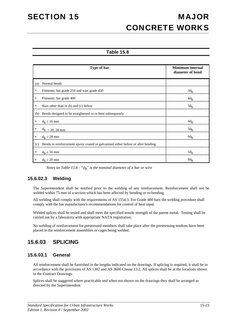
The nominal internal diameter of a reinforcement bend or hook shall be taken as the external diameter of the pin around which the reinforcement is bent. The diameter of the pin shall be not less than the value determined from Table 15.8.
SECTION 15 MAJOR CONCRETE WORKS
Standard Specification for Urban Infrastructure Works 15-23 Edition 1, Revision 0 / September 2002
Table 15.8
Type of bar Minimum internal diameter of bend
(a) Normal bends
• Fitments: bar grade 250 and wire grade 450 3db
• Fitments: bar grade 400 4db
• Bars other than in (b) and (c) below 5db
(b) Bends designed to be straightened or re-bent subsequently
• db ≤ 16 mm 4db
• db = 20, 24 mm 5db
• db ≥ 28 mm 6db
(c) Bends in reinforcement epoxy coated or galvanised either before or after bending
• db ≤ 16 mm 5db
• db ≥ 20 mm 8db
Notes on Table 15.8 : “db" is the nominal diameter of a bar or wire
15.6.02.3 Welding
The Superintendent shall be notified prior to the welding of any reinforcement. Reinforcement shall not be welded within 75 mm of a section which has been affected by bending or re-bending.
All welding shall comply with the requirements of AS 1554.3. For Grade 400 bars the welding procedure shall comply with the bar manufacturer's recommendations for control of heat input.
Welded splices shall be tested and shall meet the specified tensile strength of the parent metal. Testing shall be carried out by a laboratory with appropriate NATA registration.
No welding of reinforcement for prestressed members shall take place after the prestressing tendons have been placed in the reinforcement assemblies or cages being welded.
15.6.03 SPLICING
15.6.03.1 General
All reinforcement shall be furnished in the lengths indicated on the drawings. If splicing is required, it shall be in accordance with the provisions of AS 1302 and AS 3600 Clause 13.2. All splices shall be at the locations shown in the Contract Drawings.
Splices shall be staggered where practicable and when not shown on the drawings they shall be arranged as directed by the Superintendent
SECTION 15 MAJOR CONCRETE WORKS
Standard Specification for Urban Infrastructure Works 15-24 Edition 1, Revision 0 / September 2002
The cost of any test ordered in connection with splices not shown on the drawing shall be borne by the Contractor.
Additional splices or splices at other locations shall be at the Contractor’s expense and shall constitute a change in design detail requiring approval of the Superintendent.
15.6.03.2 Lapped Splices Laps in reinforcing bars, wire or fabric shall be as shown on the Drawings. Laps not shown on the Drawings shall be as follows for unhooked bars:-
Plain bars, Grade 250 40 bar diameters
Deformed bars, Grade 400 35 bar diameters
Hard-drawn wire 50 bar diameters
Splices in reinforcing fabric shall be so made that the overlap, measured between outermost transverse wires of each sheet of fabric is not less than the spacing of those wires plus 25mm.
15.6.03.3 Mechanical Splices Mechanical splices shall be used only at the locations shown on the drawings and shall be of the type specified or an approved equivalent. The installation of splices shall be in accordance with the manufacturere’s recommendation.
15.6.04 PROTECTIVE COATED REINFORCEMENT
Unless otherwise shown on the Drawings, if an element is specified to contain protective coated reinforcement, the same coating type shall be provided to all of that element's reinforcement and embedded ferrous metal items, including tie wires, stools, spacers, stirrups, plates, ferrules and the like, and other embedded metals shall be protected by a suitable coating.
Galvanised reinforcement shall comply with AS 4680, and the following requirements:
Minimum coating mass:
For wire: Type A.
For reinforcement: 700 g/m2.
Preparation: Pickling to AS 1627 Part 5.
Passivation: After galvanising, the galvanised coating shall be passivated by immersion in a bath of 0.2% sodium dichromate solution.
If damage occurs to the coating, either the damaged reinforcement shall be replaced, or repairs may be carried out to AS4680
Starter bars" and the like left projecting from cast concrete for future additions, otherwise unprotected and expected to be exposed to the weather for more than one month, shall be coated with a cement wash.
15.6.05 PLACING AND FIXING REINFORCEMENT
Reinforcement shall be spaced accurately to the pitches and position as shown on the Drawing. Reinforcement shall be secured against displacement by tying at all intersections with annealed iron wire ties not smaller than
SECTION 15 MAJOR CONCRETE WORKS
Standard Specification for Urban Infrastructure Works 15-25 Edition 1, Revision 0 / September 2002
1.25 mm diameter, or by approved clips. The ends of wire ties shall be bent away from nearby faces of forms so that the ties do not project into the concrete cover.
The Superintendent may approve the use of tack welding instead of wire ties on reinforcing wire. All welding of reinforcing steel shall be in accordance with AS 1554.3. Tack welding of cold-worked and hard grade bars shall not be permitted.
For bar reinforcement in the form of a mat, each bar shall be secured at alternate intersections, and at other points as required.
Ligatures in beams shall be tied to the bars in each corner of each ligature. Other longitudinal bars shall be fixed to ligatures at not more than 1000 mm intervals.
Bundled bars shall be tied together so that the bars are in closest possible contact. Tie wire shall be not less than 2.5 mm diameter at centres not more than 24 times the diameter of the smallest bar in the bundle.
In accordance with Clause 15.7.01.1, the reinforcement in each section of the work shall be approved by the Superintendent before any concrete is deposited in the section and adequate time shall be allowed for inspections and any corrective work which may be required. Notice for inspection shall not be less than four normal working hours.
Bars forming a lapped splice shall be securely wired together in at least two places, unless welded and shall comply with AS 3600 Clause 13.2.
The clear cover of any bar, including stirrups, to the nearest concrete surface shall be as shown on the Contract Drawings. Where not so indicated it shall be in accordance with AS 3600, Clause 4.10 or AS 3735 Clause 4
In no cases shall the cover be less than 1½ times the diameter of the bar.
If the spacing or cover of reinforcement does not comply with AS 3600 Clauses 8.1.7 and 4.10.2 respectively the Contractor shall notify the Superintendent and obtain instructions prior to placing concrete. The tolerance for cover to reinforcement shall be in accordance with AS 3600 Clause 19.5.3.
15.6.06 REINFORCEMENT SUPPORTS
Reinforcement shall be supported by purpose-made concrete, metal or plastic chairs. Steel shall not be supported on metal supports which extend to the surface of the concrete, on wooden supports, or on pieces of course aggregate or loose rock.
If requested by the Superintendent, the Contractor shall submit samples of proposed chairs to the Superintendent for review. Chairs which in the opinion of the Superintendent will lead to long term deterioration of the works will not be permitted.
For exposure classifications more severe than A1, as defined in AS 3600 Section 4, reinforcement shall be supported by plastic supports of adequate strength and of a shape appropriate to the location, or concrete supports of the same concrete quality as the concrete element. Chairs made from concrete of mortar that is porous shall not be permitted for use.
For reinforcement supported over membranes, damage to waterproofing membranes or vapour barriers shall be prevented by placing a metal or plastic plate under each support to prevent puncturing.
Chairs shall be spaced sufficiently close together to ensure that the specified cover is maintained during concreting, and to ensure that crushing of the chairs or penetration into the formwork does not occur.
SECTION 15 MAJOR CONCRETE WORKS
Standard Specification for Urban Infrastructure Works 15-26 Edition 1, Revision 0 / September 2002
15.6.07 FIXINGS AND EMBEDDED ITEMS
Fixings and embedded items shall comply with AS 3600 Section 14. Lifting, bracing and fixing inserts for precast units shall be in accordance with AS 3850.1 Clause 4.3.
If the locations of embedded items are not shown on the Drawings, or are shown diagrammatically, or if it is proposed to vary the locations shown, the Contractor shall submit shop drawings showing the proposed locations, clearances, cover, and the like.
In locating embedded items, the Contractor shall not cut or displace reinforcement, or cut hardened concrete, unless otherwise specified.
Fixings and embedments shall be placed such that their maximum deviation from correct position is as follows:
§ Embedded items generally: Plus or minus 10 mm;
§ Fixings, anchor bolts and the like: Plus or minus 3 mm;
§ Fixings and embedded items in precast units: To AS 3610 Table 3.43, AS 3850.1 Clause 6.4, and AS 3850.2 Clause 3.7.7 as applicable.
Where embedded pipes will contain liquid or vapour at a pressure of more than 10 KPa, they shall be tested for leaks and the results of the test provided to the Superintendent, prior to the pipe being embedded in the concrete.
15.6.08 PROTECTION OF FIXINGS
All embedded and inserted ferrous fixings (other than stainless steel) shall be provided with a galvanised surface coating passivated by dipping in 0.2% sodium dichromate solution. The galvanised surface coating shall comply with the following:
Threaded fastenings: To AS 1214.
Structural sections: To AS 4680.
15.6.09 INSERTED FIXINGS
Fixings inserted by drilling (including masonry anchors and the like), or by explosive tools, shall only be used if specified or approved by the Superintendent.
Use of such fixings shall be in strict accordance with the manufacturers' recommendations.
15.7 PLACING
15.7.01 PLACING AND COMPACTION Placing and compaction shall be in accordance with AS 3600 Clause 19.1.3 and this Specification.
15.7.01.1 Placing Movement of concrete to the pour face may be by means of suitable conveyors, clean chutes, troughs or pipes which shall be made of metal, or have metal linings, or by pumping. Water shall not be used to facilitate the movement.
Unless adequate protection is provided, concrete shall not be placed during rain or when rain appears imminent. Prior to placing concrete, the area shall be clean and moist but free from any ponding of water.
SECTION 15 MAJOR CONCRETE WORKS
Standard Specification for Urban Infrastructure Works 15-27 Edition 1, Revision 0 / September 2002
No concrete shall be mixed or placed, without the approval of the Superintendent, while the air temperature in the shade is below 5ºC or above 38ºC unless special precautions, approved by the Superintendent, are taken
The concrete shall be deposited in the forms, without separation of the aggregates. Concrete shall not be dropped freely from a height greater than 1.6 metres, or be deposited in large quantities at any point and moved or worked along the forms. Where used on steep slopes, troughs and chutes shall be equipped with baffles, or be placed in short lengths in such a way that the direction of flow of the concrete is changed.
Concrete shall be deposited in horizontal layers not exceeding 600mm in thickness and compacted such that each succeeding layer is blended into the preceding one by the compaction process. The concrete shall be placed in one continuous operation between the ends of the work and/or construction joints. Care shall be taken to fill every part of the forms and to work the coarser aggregate back from the face.
Concrete shall not be moved after it has been in the forms for more than 10 minutes.
The Contractor shall keep on site and make available for inspection a log book recording each placement of concrete including:
• date;
• the portion of work;
• specified grade and source of concrete;
• slump measurements;
• volume placed.
Concrete affected by rain before it has set, including during mixing, transport or placing, shall be liable to rejection.
The Contractor shall minimise shrinkage effects by pouring the sections of the work between construction joints in a sequence such that there will be suitable time delays between adjacent pours. The Contractor shall submit a proposed sequence and times for approval.
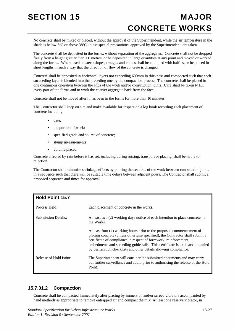
Hold Point 15.7
Process Held: Each placement of concrete in the works.
Submission Details: At least two (2) working days notice of each intention to place concrete in the Works.
At least four (4) working hours prior to the proposed commencement of placing concrete (unless otherwise specified), the Contractor shall submit a certificate of compliance in respect of formwork, reinforcement, embedments and screeding guide rails. This certificate is to be accompanied by verification checklists and other details showing compliance.
Release of Hold Point: The Superintendent will consider the submitted documents and may carry out further surveillance and audit, prior to authorising the release of the Hold Point.
15.7.01.2 Compaction Concrete shall be compacted immediately after placing by immersion and/or screed vibrators accompanied by hand methods as appropriate to remove entrapped air and compact the mix. At least one reserve vibrator, in
SECTION 15 MAJOR CONCRETE WORKS
Standard Specification for Urban Infrastructure Works 15-28 Edition 1, Revision 0 / September 2002
working order, shall be provided as standby during concreting operations. Form vibrators shall be used where use of immersed vibrators is impracticable. Concrete shall be fully compacted and entrapped air removed, but the concrete shall not be over vibrated such that segregation is caused. Vibrators shall not come into contact with partially hardened concrete, or reinforcement embedded in it. Vibrators shall not be allowed to rest on reinforcement or be used to move concrete along the forms.
Exposed surfaces of the concrete shall be struck off and finished with a wooden float. Where shown on the Drawings corners and edges shall be left neatly rounded or chamfered. Re-entrant angles shall be neatly filleted.
15.7.02 COLD WEATHER PLACING
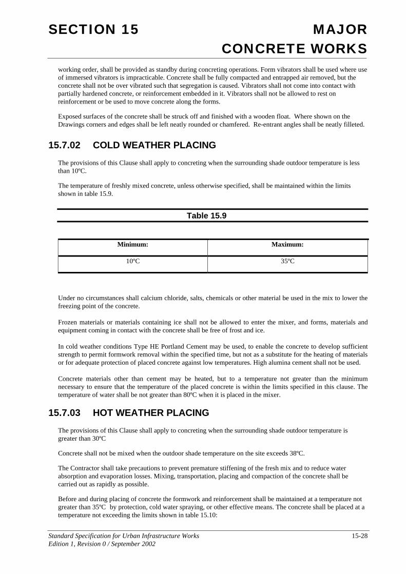
The provisions of this Clause shall apply to concreting when the surrounding shade outdoor temperature is less than 10ºC.
The temperature of freshly mixed concrete, unless otherwise specified, shall be maintained within the limits shown in table 15.9.
Table 15.9
Minimum: Maximum:
10ºC 35ºC
Under no circumstances shall calcium chloride, salts, chemicals or other material be used in the mix to lower the freezing point of the concrete.
Frozen materials or materials containing ice shall not be allowed to enter the mixer, and forms, materials and equipment coming in contact with the concrete shall be free of frost and ice.
In cold weather conditions Type HE Portland Cement may be used, to enable the concrete to develop sufficient strength to permit formwork removal within the specified time, but not as a substitute for the heating of materials or for adequate protection of placed concrete against low temperatures. High alumina cement shall not be used.
Concrete materials other than cement may be heated, but to a temperature not greater than the minimum necessary to ensure that the temperature of the placed concrete is within the limits specified in this clause. The temperature of water shall be not greater than 80ºC when it is placed in the mixer.
15.7.03 HOT WEATHER PLACING
The provisions of this Clause shall apply to concreting when the surrounding shade outdoor temperature is greater than 30ºC
Concrete shall not be mixed when the outdoor shade temperature on the site exceeds 38ºC.
The Contractor shall take precautions to prevent premature stiffening of the fresh mix and to reduce water absorption and evaporation losses. Mixing, transportation, placing and compaction of the concrete shall be carried out as rapidly as possible.
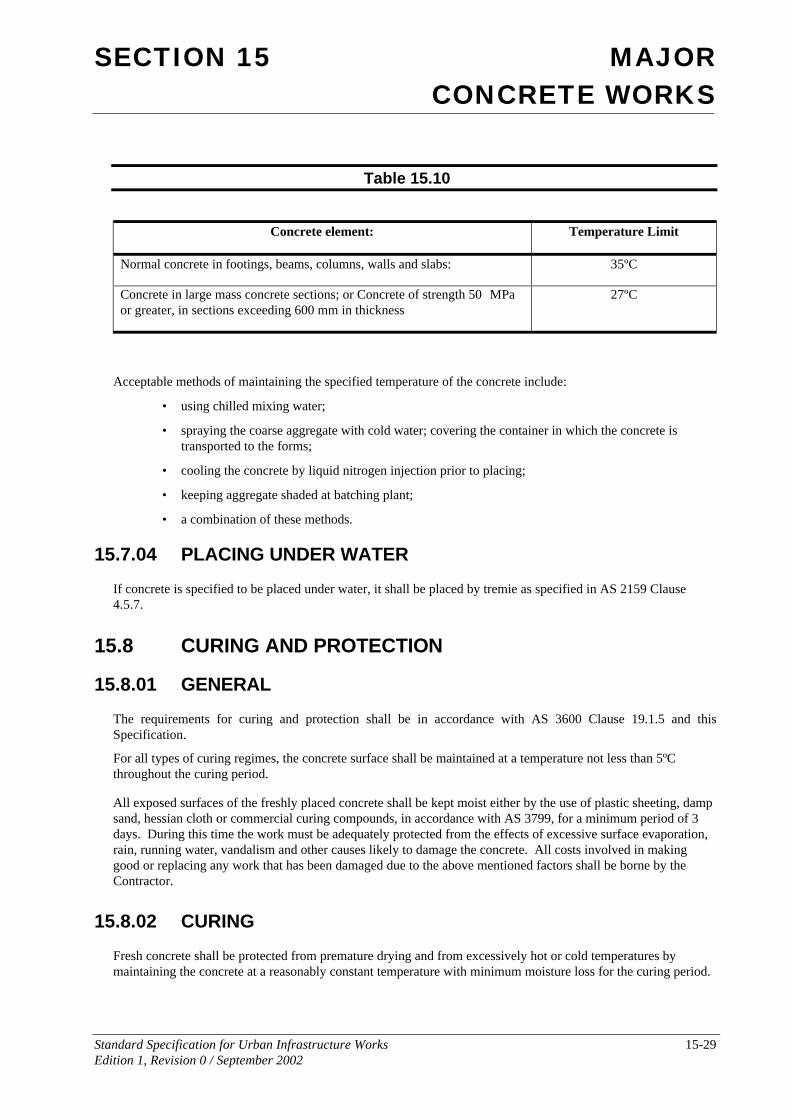
Before and during placing of concrete the formwork and reinforcement shall be maintained at a temperature not greater than 35ºC by protection, cold water spraying, or other effective means. The concrete shall be placed at a temperature not exceeding the limits shown in table 15.10:
SECTION 15 MAJOR CONCRETE WORKS
Standard Specification for Urban Infrastructure Works 15-29 Edition 1, Revision 0 / September 2002
Table 15.10
Concrete element: Temperature Limit
Normal concrete in footings, beams, columns, walls and slabs: 35ºC
Concrete in large mass concrete sections; or Concrete of strength 50 MPa or greater, in sections exceeding 600 mm in thickness
27ºC
Acceptable methods of maintaining the specified temperature of the concrete include:
• using chilled mixing water;
• spraying the coarse aggregate with cold water; covering the container in which the concrete is transported to the forms;
• cooling the concrete by liquid nitrogen injection prior to placing;
• keeping aggregate shaded at batching plant;
• a combination of these methods.
15.7.04 PLACING UNDER WATER
If concrete is specified to be placed under water, it shall be placed by tremie as specified in AS 2159 Clause 4.5.7.
15.8 CURING AND PROTECTION
15.8.01 GENERAL
The requirements for curing and protection shall be in accordance with AS 3600 Clause 19.1.5 and this Specification.
For all types of curing regimes, the concrete surface shall be maintained at a temperature not less than 5ºC throughout the curing period.
All exposed surfaces of the freshly placed concrete shall be kept moist either by the use of plastic sheeting, damp sand, hessian cloth or commercial curing compounds, in accordance with AS 3799, for a minimum period of 3 days. During this time the work must be adequately protected from the effects of excessive surface evaporation, rain, running water, vandalism and other causes likely to damage the concrete. All costs involved in making good or replacing any work that has been damaged due to the above mentioned factors shall be borne by the Contractor.
15.8.02 CURING
Fresh concrete shall be protected from premature drying and from excessively hot or cold temperatures by maintaining the concrete at a reasonably constant temperature with minimum moisture loss for the curing period.
SECTION 15 MAJOR CONCRETE WORKS
Standard Specification for Urban Infrastructure Works 15-30 Edition 1, Revision 0 / September 2002
Acceptable methods of curing include the following:
• ponding or continuous sprinkling with water (moist curing);
• an impermeable membrane;
• an absorptive cover kept continuously wet;
• steam curing;
• retention of impermeable formwork
• an approved curing compound.
If it is proposed to use a liquid membrane-forming curing compound, the Contractor shall submit the following information to the Superintendent:
• certified test results for water retention to AS 3799 Appendix B;
• evidence that an acceptable final surface colour will be obtained;
• evidence of compatibility with applied finishes, if any;
• methods of obtaining the required adhesion for toppings, render and the like.
Curing compounds shall be to AS 3799. Wax-based or chlorinated rubber-based curing compounds shall not be used on surfaces forming substrates to concrete toppings, bridge decks, cement-based render and the like.
The curing compound supplier shall implement and maintain a quality system in accordance with ISO 9002, as a means of ensuring that the product conforms to the Specification requirements.
Curing shall commence immediately after finishing, and shall be applied continuously until the cumulative number of hours (measured from time of placing), not necessarily consecutive, during which the air temperature in contact with the concrete is above 10ºC, totals not less than the following:
• For durability exposure categories A1 and A2: 72 hours.
• For durability exposure categories B1, B2, and C: 168 hours.
For concrete placed during hot weather (as defined by Clause 15.7.03), curing shall be by one of the methods identified above, but not by curing compound alone.
Curing shall commence as soon as is practicable after concrete placement. Where the temperature exceeds 30ºC. or where subject to drying winds, protection shall commence immediately, either by curing or, until curing begins, with a fog spray application of aliphatic alcohol evaporation retardant.
For visually important surfaces uniform curing methods shall be used on adjacent surfaces so as to produce uniform colour.
15.8.03 PROTECTION
The Contractor shall inform the Superintendent before loading the concrete structure. The concrete shall be protected from damage due to load overstresses, heavy shocks and excessive vibrations, particularly during the curing period. Where it is proposed that the structure needs to sustain any construction loads, the Contractor shall provide calculations to justify such proposals.
Finished concrete surfaces shall be protected from damage from any cause, including mortar splashes and stains, timber stains, rust stains, chemical attack, additives, curing compounds, protective coatings, rain, running water, and the like.
SECTION 15 MAJOR CONCRETE WORKS
Standard Specification for Urban Infrastructure Works 15-31 Edition 1, Revision 0 / September 2002
15.9 PRESTRESSING
15.9.01 GENERAL
This Section, in conjunction with the Drawings, provides the requirements for the supply and installation of prestressing tendons including the necessary anchorages, ducts, supports, grout, anchorage protection and order of stressing.
The prestressing data and requirements shown in the Contract have been used as the basis for design. The Contractor may propose the use of an alternative prestressing system. In any case the Contractor shall submit to the Superintendent as part of its Project Quality Plan, full details, including calculations and drawings, of the proposed system. This submission shall be in accordance with Clause 15.9.03. The Contractor shall be responsible for the selection and use of the prestressing system if different to that shown in the Contract.
Prestressing shall be carried out in accordance with AS 3600 Clause 19.3 and this Specification. Concrete cover shall be in accordance with AS 3600 Clause 4.10 or AS 3735 Clause 4.4 as applicable. The tolerance on the location of sheathing shall be 3 mm from the true position except that the required cover shall not be reduced.
Where ducts are formed with sheaths, the sheathing shall be manufactured from galvanised metal strip or other such specified material that is strong enough to transfer the tendon stresses into the body of the concrete.
Where tendons are to be installed after concreting, temporary stiffening shall be provided within the sheath such that the duct shape and profile are maintained during concreting. After concreting the temporary stiffening shall be removed and the sheath curvature and continuity shall be verified with a suitable gauge before installing the tendon.
Stressing shall not commence until the concrete has attained the required transfer strength.
Tendons shall not be cut nor ducts grouted until the Contractor has submitted documented evidence, pursuant to Clause 15.9.06 of this Specification, that the required tendon forces have been achieved.
On completion of stressing and grouting, all anchorage parts and parts of tendons anchored thereto shall be permanently protected. Wires or tendons shall not be cut or bent within 300 mm of the anchorages until 7 days after grouting. Cutting shall be with a disc cutter; flame cutting is not permitted. Not less than 40 mm of cover over the cut tendons shall be provided when the recesses are concreted.
15.9.02 PRESTRESSING MATERIALS
15.9.02.1 Supply of Tendons Tendons shall comply with the requirements of AS 1310 and AS 1311.
Each delivery of materials shall be accompanied by documentation showing the lot numbers from which each coil is taken, together with the relevant test certificates in accordance with AS 1311 and including data on chemical composition and relaxation.
15.9.02.2 Handling and Treatment of Tendons Tendons shall be kept free from loose or thick rust, oil, grease, tar, paint, mud or any other deleterious substance but shall not be brought to a smooth polished condition. A slight film of rust will not be regarded as harmful, but the steel shall not be visibly pitted by rust.
Tendons that are damaged, kinked or bent shall not be used.
SECTION 15 MAJOR CONCRETE WORKS
Standard Specification for Urban Infrastructure Works 15-32 Edition 1, Revision 0 / September 2002
15.9.02.3 Storage of Tendons Material for tendons not currently in use shall be stored in a weatherproof environment and supported above the surface of the ground in a manner which will prevent damage to the steel.
15.9.03 PRESTRESSING SYSTEM
Prior to commencing prestressing work the Contractor shall, as part of its PROJECT QUALITY PLAN submit to the Superintendent the following details of the prestressing system:
(i) Shop drawings, showing:
• profiles, sizes and details of tendons, proprietary anchorages, ducts, duct formers, sheathing, end block reinforcement and other associated components;
• stressing requirements including sequence of stressing, jacking forces, tendon elongations, gauge pressures, and the basis of assumed loss calculations;
• number, size and position of grout openings, vents and drain holes in the ducts;
• proposed fabrication, handling and fixing methods for tendons and sheathing; stressing and grouting equipment; grout mix including additives, if any.
(ii) Calculations, indicating:
• jacking forces, extensions and losses for each stressing stage;
• anchorage zone details and reinforcement;
• anticipated deflections and if necessary proposed pre-camber.
(iii) Equipment Certificates:
• current calibration certificates for tensioning and tension measuring equipment.
(iv) Material Tests:
• certified test results for compressive strength and shrinkage of the proposed grout mix;
• test certificates of compliance with AS 1314 for all tendon anchorages and couplers;
• test certificates of compliance with the relevant Australian Standards for each delivery of each type of prestressing steel.
15.9.04 PRESTRESSING EQUIPMENT
Both force and extension measurements shall be taken during all tensioning operations. Force measurements shall be recorded to an accuracy of 2% and extension measurements to an accuracy of 1mm. The force measurements may be made by dynamometers or pressure gauges. Where the latter are used there shall be a minimum of two gauges on each jack selected so as to be used at between 50% and 90% of their full capacity when the final load measurements are taken on any tendon.
Pressure gauges shall comply with AS 1349. Certified calibration by a NATA approved laboratory will be required for all dynamometers or pressure gauges. Calibration shall be carried out at intervals not exceeding 6 months or more frequently if required by the Superintendent.
Friction losses in prestressing jacks shall be measured and calibrated at least once a year, or after re-sealing.
SECTION 15 MAJOR CONCRETE WORKS
Standard Specification for Urban Infrastructure Works 15-33 Edition 1, Revision 0 / September 2002
15.9.05 TENSIONING PROCEDURE
The Contractor shall inform the Superintendent not less than three (3) days prior to commencement of tensioning. Tensioning shall be carried out only in the presence of the Superintendent unless otherwise directed, by trained crews experienced in this type of work and the use of the particular equipment involved. No member shall be stressed until the concrete in it has attained the minimum age at which control test cylinders have reached the specified compressive strength.
Hold Point 15.8
Process Held: Pretensioning or Post-tensioning of each member or line of members.
Submission Details: At least three (3) working days prior to the proposed tensioning, for each member or line of members, the Contractor shall submit the stressing calculations, Engineer's certification and the representative test certificates for each member and notification of the time of commencement of stressing.
Release of Hold Point: The Superintendent will consider the submitted documents prior to authorising the release of the Hold Point.
The tendon force shall be raised to the specified maximum value uniformly such that the force is gradually transferred to the concrete. Extension readings shall be commenced after 10% of the load has been applied in order to ensure that the datum is set after slack cable has been taken up. For multi-strand cables, each of the strands shall be marked with chalk or by other means so that any movement of strands relative to each other during tensioning may be observed. Where stressing from one end only is permitted the draw-in at the end removed from the jack shall be measured so that the appropriate allowance can be made in the measured extensions.
Every endeavour shall be made to obtain the force required as shown in the Drawings or requested by the Superintendent. A tolerance of ±5% of the required force will then be permitted for individual tendons, provided that the total force in the member is within 2% of the required value. Where these requirements are not met, a nonconformance report shall be raised. When the agreed disposition is to reject the member, it shall be removed from the works at no additional cost to the Principal. .
The measured extensions shall be regarded as a check on the loss of force due to friction in the sheathing. At the start of the prestressing work, the Contractor shall carry out sufficient tests to determine the actual friction and wobble factors which are applicable to the Works and which should be used in the calculation of theoretical extensions.
When the specified jacking force in the tendon is reached, the extension of the tendon shall be measured and shall agree with the calculated theoretical extension to within ±5%. Otherwise the Superintendent may direct that the tendon be released from the jack(s) and restressed, in which case the stress-strain curve applicable to a second stressing shall be used in determining the elongation required. Should the tendon have been stressed by one jack only, where practicable the Superintendent may direct that jacks be used at both ends of the tendon for the restressing operation. Any breaks in stressing are to be notified to the Superintendent and at least one (1) days notice given to the Superintnedent of intention to commence restressing.
All calculations shall be certified by a Chartered Professional Engineer of the Institution of Engineers, Australia or equivalent.
If the stressing calculations are shown to be incorrect or the stressing method needs to be changed, the following Hold Point shall apply.

SECTION 15 MAJOR CONCRETE WORKS
Standard Specification for Urban Infrastructure Works 15-34 Edition 1, Revision 0 / September 2002
Hold Point 15.9
Process Held: Further stressing (If revised calculations or stressing methods are required).
Submission Details: Revised stressing calculations with a Chartered Professional Engineer's certification or revised stressing method.
Release of Hold Point: The Superintendent will consider the submitted documents prior to authorising the release of the Hold Point
If the measured friction and wobble factors are such as would cause greater loss of tendon force than that computed using the design friction and wobble factors given on the Drawings, then the Superintendent may direct that the tendons be treated with an approved water soluble oil to reduce friction to the level given by the design factors.
During anchorage of the strand tendons, the strands shall be marked to allow draw-in to be measured. If the average draw-in is greater than that specified in the drawings, the Superintendent may direct that the tendon be completely released and the tensioning operation repeated.
After a tendon has been anchored, the jack pressure shall be released gradually and evenly, so as to cause no shock to the anchorage or tendon.
In the event of the tendon breaking or slipping after tensioning so that the allowable tolerances as specified are exceeded, the tendon shall be released, replaced if necessary and restressed.
15.9.06 PRESTRESSING RECORDS
After prestressing, the Contractor shall furnish, in an approved form, the following information:
• concrete mix and quality;
• details of placing and curing, including dates;
• details of placing of reinforcement and prestressing tendons;
• date of prestressing operation;
• name of operator;
• type and identification numbers of equipment used;
• piston areas;
• identification of tendons;
• stressing method (single or double end, monostrand or multistrand);
• calculated tendon extension at each stressing stage;
• initial force or pressure where tendons are marked for measurement of
• elongations;
• final force or pressure and elongation on completion of tensioning;
• elongation remaining after release of jacks;
• tendon breakage;
• ramming pressure, if applicable.
SECTION 15 MAJOR CONCRETE WORKS
Standard Specification for Urban Infrastructure Works 15-35 Edition 1, Revision 0 / September 2002
15.9.07 GROUTING DUCTS
The grouting equipment shall be capable of continuous operation with little variation of pressure and shall include a system of recirculating the grout whilst actual grouting is not in progress. Either a piston or a screw pump shall be used. The use of manually powered machines or compressed air will not be permitted. The pump shall be capable of exerting delivery pressures of at least 0.7 MPa and shall be fitted with a pressure gauge having a full scale reading of 2 MPa. The capacity of the pump shall be sufficient to achieve a forward speed of the grout in the sheathing of 6-12 metres per minute. The pump and the mixer shall be powered by separate motors. All grout entering the pump shall be screened by a sieve having 2mm maximum clear openings.
Methods of mixing and pumping shall be such as will minimise turbulence in the grout. Grouting shall not proceed if the grout has become aerated because of turbulence in the mixer or pump.
Grout tubes shall be provided adjacent to all tendon anchorages. Intermediate vent tubes shall be provided at least at all low and high points, as required to ensure the duct will be completely filled during grouting.
All grout and vent tubes shall be at least 500mm long, have a minimum internal diameter of 20mm, and be provided with:
(i) A threaded connection to the duct at the lower end;
(ii) A threaded connection for the grout pump line at the upper end;
(iii) A high pressure gas tap to permit quick cut-off of the grout flow.
All sheathing shall be clean and free of deleterious materials that would impair bonding of the grout or interfere with grouting procedures. The sheathing shall be filled with clean water having a pressure head at all locations of not less than one (1) metre. Checks shall be made of the water tightness of each sheath after it is filled with water in this way. The Contractor shall take measures to seal any leaks between sheaths before grouting of the sheathing is commenced. The Contractor shall be permitted to use oil-free compressed air to remove completely the previously injected water from the sheathing prior to the commencement of grout injection.
Before grout injection commences all air in the pump and the hose shall be expelled. Grout shall then be pumped through the sheathing to displace all the air or the previously injected water and continued until the consistency of the grout flowing from the free end is the same as that of the injected grout. The outlet pipe shall then be closed off. In the case of tendons containing intermediate vent tubes, these tubes shall be sealed in a similar manner, working progressively from the grouting end, before the outlet tubes at the far end are closed.
Generally, grout shall be injected in one continuous operation from the lowest point in the sheathing and shall be allowed to flow from tube openings until all water and air has been expelled from the sheathing. However, where the Drawings show or the Superintendent directs that two tubes be placed one (1.0) m apart on crests, grouting shall commence from the low point in the sheathing and the grout pumped uphill past the first of the pair of tubes at the crest and allowed to flow from the second tube at the crest. Grouting shall then continue from the adjacent low point (or anchorage if at a stage coupling position) on the other side of the crest and allowed to flow from the same tube. Finally, grout shall be pumped through the first of the pair of tubes at the crest and out of the second tube at the crest to ensure that all air and water has been expelled from the sheathing in the flat region at the crest.
At the conclusion of grouting the system shall be sealed and pressurised to 0.7 MPa for circular ducts and 0.21 MPa otherwise.
As a protection against blockage the Contractor shall endeavour to grout all sheaths in one section in one day. Where this cannot be achieved those sheaths which have not been finished as described in the foregoing shall be flushed clean with water and then blown with dry air.
Grouting shall not be permitted when the air temperature in the shade is less than 4ºC or greater than 32ºC.
The Contractor shall provide standby flushing equipment capable of developing a pumping pressure of 2 MPa and of sufficient capacity to flush out any partially grouted sheathing.
SECTION 15 MAJOR CONCRETE WORKS
Standard Specification for Urban Infrastructure Works 15-36 Edition 1, Revision 0 / September 2002
For each duct grouted, the Contractor shall keep, and furnish to the Superintendent, a record identifying the duct and tendons, giving the stressing and grouting dates, and showing the composition of the grout (water/cement ratio, admixtures), grout tests, and details of grouting (interruptions, topping up, etc.).
Hold Point 15.10
Process Held: Grouting of ducts /and or cutting of tendons.
Submission Details: At least one (1) working days prior to grouting of ducts /and or cutting of tendons the Contractor shall submit documentary evidence that the required tendon forces have been achieved for each member or line of members.
Release of Hold Point: The Superintendent will consider the submitted documents prior to authorising the release of the Hold Point.
15.10 PRECAST UNITS
15.10.01 GENERAL
Precast units comprise all concrete elements manufactured in other than their final position and include elements manufactured on site such as tilt-up panels.
Each unit shall be identified by marks which shall:
• remain legible until after the unit has been fixed in place;
• not be visible in the completed structure;
• show the date of casting;
• show the correct orientation of the unit;
• on other than units manufactured as a standard product, indicate the locations within the structure in accordance with an approved marking plan.
Precast units shall be handled in accordance with the recommended safety requirements, methods and equipment of AS 3850.1 and AS 3850.2.
15.10.02 VENEERED CONSTRUCTION
Veneered construction shall not be used unless specified.
If veneered construction is specified, the Contractor shall use methods which ensure that delamination of the veneer will not occur. Veneered units shall be liable to be rejected unless the second layer is placed whilst the first is still plastic.
The specified cover to reinforcement shall be exclusive of any applied finish or any finishing layer that has thermal or chemical properties different from the main body of concrete in the unit. If a facing layer is permitted to be included in the cover, the reinforcement shall not be placed at the interface between the layers.
SECTION 15 MAJOR CONCRETE WORKS
Standard Specification for Urban Infrastructure Works 15-37 Edition 1, Revision 0 / September 2002
15.10.03 HANDLING PRECAST UNITS
Precast units shall not be lifted or supported at other than specified points. Handling methods shall be used which do not overstress, warp or damage the units. No superimposed loads or secondary load components resulting from handling, storage or transport shall be placed on any member.
Each lifting device shall be designed for a working load not less than 1.65 times the maximum calculated static load at that point and an ultimate load not less than 4 times the maximum static load.
Lifting attachments, holes and other temporary fixings for handling purposes shall not be placed on visible faces of units unless specified. The Contractor shall recess lifting attachments such as ferrules, or other types of cast-in fixings, and provide a plug for sealing. Temporary attachments shall be removed after erection and sealed or otherwise to make good any residual recesses. The Contractor shall include in its Project Quality Plan, details of location of lifting points and lifting devices.
Temporary supports shall be timber and shall support the unit over its full width. The ground or space between members shall be levelled to prevent accidental support being provided other than on the temporary supports. Temporary supports shall be of sufficient size so that settlement of the foundation material will not occur. However, in no case shall the supports at ground level be less than 200mm wide and 150mm thick.
The minimum clearance from ground level to the underside of a member shall be 100mm.
Girders and planks shall be supported at positions within 300mm either side of the boundary of the bearing locations at which they will be finally supported in the structure. Other members shall be supported at the positions as shown in the Drawings.
The Contractor shall transport the units in a manner which does not damage them. The Contractor shall, prior to transport, submit to the Superintendent a certificate from an Engineer eligible for Corporate Membership of the Institution of Engineers, Australia, stating that the method of support and transport will not overstress the units. No member shall be transported to site until it is at least seven days old
Precast concrete units may be stacked on top of each other. Each layer shall be separated from the next layer by at least 75mm, by temporary supports placed in line vertically at the specified support points.
Where stacking of girders is required by the Contractor, the design of the stacking arrangement shall be carried out by an Engineer eligible for Corporate Membership of the Institution of Engineers, Australia and a certificate shall be provided to the Superintendent, prior to stacking girders, stating that the proposed stacking arrangement will not overstress or damage any girder so stacked.
Consideration shall be given to the relief of temperature, shrinkage, creep and any other effects on the stacking arrangements.
Units shall be protected against staining, discolouration and damage.
15.10.04 PRECASTING SHOP DRAWINGS
The contractor shall submit shop drawings of precast units showing the proposed details for their design, manufacture, assembly, transport and installation.
Precasting shall not commence until permission to use the shop drawings has been given by the Superintendent.
Precasting shop drawings shall indicate:
• project title and manufacturer's name;
• the information specified in AS 3850.1 Clause 5.4;
SECTION 15 MAJOR CONCRETE WORKS
Standard Specification for Urban Infrastructure Works 15-38 Edition 1, Revision 0 / September 2002
• shape or profile drawings (submit these prior to fabrication of moulds and tooling);
• calculations showing method of complying with specified performance requirements;
• concrete mix and type of cement if special class concrete;
• formwork type;
• surface finish class and surface treatment, if applicable;
• curing and protection methods;
• equipment and methods for handling, transport and installation;
• calculated maximum loadings on lifting and bracing inserts and attachments;
• evidence of load capacity of lifting and bracing inserts and attachments in the form of test reports or calculations.
If it is proposed to lift the units by their designated lifting points before 28 day strength has been achieved, the Contractor shall provide evidence to demonstrate that the unit is strong enough to carry its own weight without residual deflection on removal of the support.
Hold Point 15.11
Process Held: Manufacture of precast concrete elements.
Submission Details: At least five (5) working days prior to proposed manufacture of precast concrete elements the Contractor shall submit shop drawings and details for design, manufacture, assembly, transport and installation of precast concrete elements.
Release of Hold Point: The Superintendent will consider the documentation prior to authorising the release of the Hold Point.
15.10.05 PRECASTING PROTOTYPES
Where prototypes of precast elements are specified, manufacture of the units shall not commence until the Superintendent has approved the prototypes.
Prototypes shall be cast to the design and methods shown on the shop drawings and shall be maintained on site, undamaged and protected from discolouration for comparison with manufactured precast units.
Each prototype shall be tested for the properties and tolerances specified. If structural performance requirements are specified for the precast unit, static load tests to AS 3600 Section 21 shall be performed. However, if satisfied with the calculations for performance requirements provided with the precasting shop drawings, the Superintendent may waive the requirement for structural testing.
The Superintendent may accept the prototypes as test panels for surface finish and/or colour. Otherwise separate panels shall be produced for this purpose.
SECTION 15 MAJOR CONCRETE WORKS
Standard Specification for Urban Infrastructure Works 15-39 Edition 1, Revision 0 / September 2002
Hold Point 15.12
Process Held: Manufacture of precast concrete elements where prototypes of precast elements are specified.
Submission Details: At least three (3) working days prior to proposed manufacture precast concrete elements where prototypes of precast elements are specified, the Contractor shall provide notification that the precast prototype element may be inspected and submit any supporting documentation as required by the Contract and AS 3600.
Release of Hold Point: The Superintendent will consider the supporting documentation and the finished precast prototype element prior to authorising the release of the Hold Point..
15.10.06 CERTIFICATION BY THE CONTRACTOR
Prior to members being incorporated into the Works, the Contractor shall submit to the Superintendent a certificate for each unit which states that it conforms to the Specification and that all nonconformances have been rectified. The certificate shall be accompanied by a check-list and the records for each unit verifying conformance.
Hold Point 15.13
Process Held: Each installation of precast units cast off the site in the Works.
Submission Details: At least two (2) working days prior to the proposed commencement of installation of precast units the Contractor shall submit a certificate for each unit which states that it conforms to the Specification and that all non-conformances have been rectified
Release of Hold Point: The Superintendent will consider the documentation and inspect the precast unit prior to authorising the release of the Hold Point.
15.10.07 INSTALLING PRECAST UNITS
Precast units shall be fixed securely in their final positions within the specified tolerances. The Contractor shall supply the necessary components and materials, including fixings, temporary fixings, braces, shims, jointing strips, sealant, flashings, grout, mortar and the like.
The following information is to be supplied to the Superintendent at least two (2)days prior to commencement of any installation of precast units:
(a) details of any cranes, falsework and/or other equipment proposed for lifting, positioning and temporary support and bracing of the members;
(b) details of the method to be used for erection; and
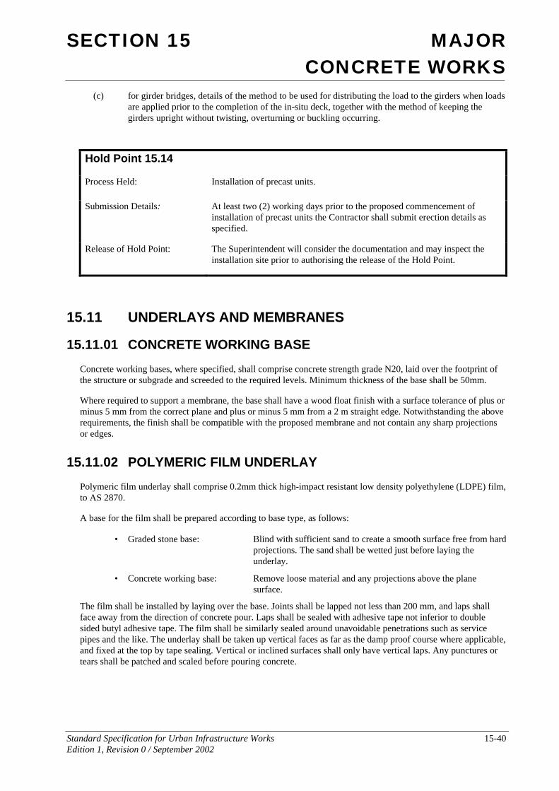
SECTION 15 MAJOR CONCRETE WORKS
Standard Specification for Urban Infrastructure Works 15-40 Edition 1, Revision 0 / September 2002
(c) for girder bridges, details of the method to be used for distributing the load to the girders when loads are applied prior to the completion of the in-situ deck, together with the method of keeping the girders upright without twisting, overturning or buckling occurring.
Hold Point 15.14
Process Held: Installation of precast units.
Submission Details: At least two (2) working days prior to the proposed commencement of installation of precast units the Contractor shall submit erection details as specified.
Release of Hold Point: The Superintendent will consider the documentation and may inspect the installation site prior to authorising the release of the Hold Point.
15.11 UNDERLAYS AND MEMBRANES
15.11.01 CONCRETE WORKING BASE
Concrete working bases, where specified, shall comprise concrete strength grade N20, laid over the footprint of the structure or subgrade and screeded to the required levels. Minimum thickness of the base shall be 50mm.
Where required to support a membrane, the base shall have a wood float finish with a surface tolerance of plus or minus 5 mm from the correct plane and plus or minus 5 mm from a 2 m straight edge. Notwithstanding the above requirements, the finish shall be compatible with the proposed membrane and not contain any sharp projections or edges.
15.11.02 POLYMERIC FILM UNDERLAY
Polymeric film underlay shall comprise 0.2mm thick high-impact resistant low density polyethylene (LDPE) film, to AS 2870.
A base for the film shall be prepared according to base type, as follows:
• Graded stone base: Blind with sufficient sand to create a smooth surface free from hard projections. The sand shall be wetted just before laying the underlay.
• Concrete working base: Remove loose material and any projections above the plane surface.
The film shall be installed by laying over the base. Joints shall be lapped not less than 200 mm, and laps shall face away from the direction of concrete pour. Laps shall be sealed with adhesive tape not inferior to double sided butyl adhesive tape. The film shall be similarly sealed around unavoidable penetrations such as service pipes and the like. The underlay shall be taken up vertical faces as far as the damp proof course where applicable, and fixed at the top by tape sealing. Vertical or inclined surfaces shall only have vertical laps. Any punctures or tears shall be patched and scaled before pouring concrete.
SECTION 15 MAJOR CONCRETE WORKS
Standard Specification for Urban Infrastructure Works 15-41 Edition 1, Revision 0 / September 2002
15.11.03 MEMBRANE SYSTEMS
Sheet membranes shall either be bituminous multi-layer systems, to the relevant requirements of AS CA55, or single layer systems of sheets fixed and lapped with appropriate adhesive or heat welded by gas torch ("torch on").
Seamless membranes shall be applied in liquid or gel form and air cured to form a seamless film.
The following details of membranes shall be submitted to the Superintendent:
• Proprietary item;
• Application rates/thicknesses;
• Application techniques.
The manufacturer's printed recommendations for details and application of approved membranes shall form part of the Specification.
Membranes shall only be applied to dry, smooth, firm, continuous surfaces, clean and free from loose or foreign matter. The substrate shall be tested for dryness in accordance with AS 1884 Appendix A. Coving or fillets shall be applied on all internal corners. External corners and edges shall have an arris or rounding.
The membrane shall be protected after installation with a permanent protective boarding or a prefabricated, fully filtered, vertical subsoil drainage layer. A low melt bitumen or suitable solvent-free adhesive shall be used to adhere the protection boards to the membrane with maximum 6 mm gap at joints in the boards.
15.12 JOINTS
15.12.01 CONSTRUCTION JOINTS
Construction joints shall be in accordance with AS 3600 Clause 19.4. 1.
The Contractor shall not relocate or eliminate a construction joint, or make a construction joint not shown on the Drawings, without prior approval of the Superintendent. This includes emergency construction joints made necessary by unforeseen interruptions to the concrete pour.
Before fresh concrete is placed at a construction joint, the hardened concrete surface of the joint shall be roughened and cleaned so that all loose or soft material, free water, foreign matter and laitance is removed. Care shall be taken not to disturb any reinforcement or damage any adjoining concrete faces. Just prior to placement, the hardened concrete surface of the construction joint and the projecting reinforcement shall be washed clean, and the concrete surface saturated with water without leaving loose material or free water.
Unless otherwise shown on the Drawings or specified, the surfaces of adjoining pours shall be butt joined. In visually important surfaces the joint shall be straight and true, and free from impermissible blemishes relevant to its surface finish class.
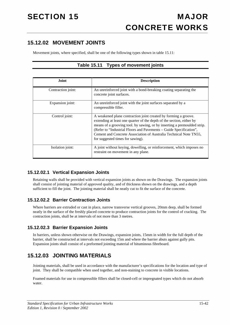
SECTION 15 MAJOR CONCRETE WORKS
Standard Specification for Urban Infrastructure Works 15-42 Edition 1, Revision 0 / September 2002
15.12.02 MOVEMENT JOINTS
Movement joints, where specified, shall be one of the following types shown in table 15.11:
Table 15.11 Types of movement joints
Joint Description
Contraction joint: An unreinforced joint with a bond-breaking coating separating the concrete joint surfaces.
Expansion joint: An unreinforced joint with the joint surfaces separated by a compressible filler.
Control joint: A weakened plane contraction joint created by forming a groove. extending at least one quarter of the depth of the section, either by means of a grooving tool. by sawing, or by inserting a premoulded strip. (Refer to “Industrial Floors and Pavements – Guide Specification”, Cement and Concrete Association of Australia Technical Note TN55, for suggested times for sawing).
Isolation joint: A joint without keying, dowelling, or reinforcement, which imposes no restraint on movement in any plane.
15.12.02.1 Vertical Expansion Joints Retaining walls shall be provided with vertical expansion joints as shown on the Drawings. The expansion joints shall consist of jointing material of approved quality, and of thickness shown on the drawings, and a depth sufficient to fill the joint. The jointing material shall be neatly cut to fit the surface of the concrete.
15.12.02.2 Barrier Contraction Joints Where barriers are extruded or cast in place, narrow transverse vertical grooves, 20mm deep, shall be formed neatly in the surface of the freshly placed concrete to produce contraction joints for the control of cracking. The contraction joints, shall be at intervals of not more than 3 metres.
15.12.02.3 Barrier Expansion Joints In barriers, unless shown otherwise on the Drawings, expansion joints, 15mm in width for the full depth of the barrier, shall be constructed at intervals not exceeding 15m and where the barrier abuts against gully pits. Expansion joints shall consist of a preformed jointing material of bituminous fibreboard.
15.12.03 JOINTING MATERIALS
Jointing materials, shall be used in accordance with the manufacturer’s specifications for the location and type of joint. They shall be compatible when used together, and non-staining to concrete in visible locations.
Foamed materials for use in compressible fillers shall be closed-cell or impregnated types which do not absorb water.
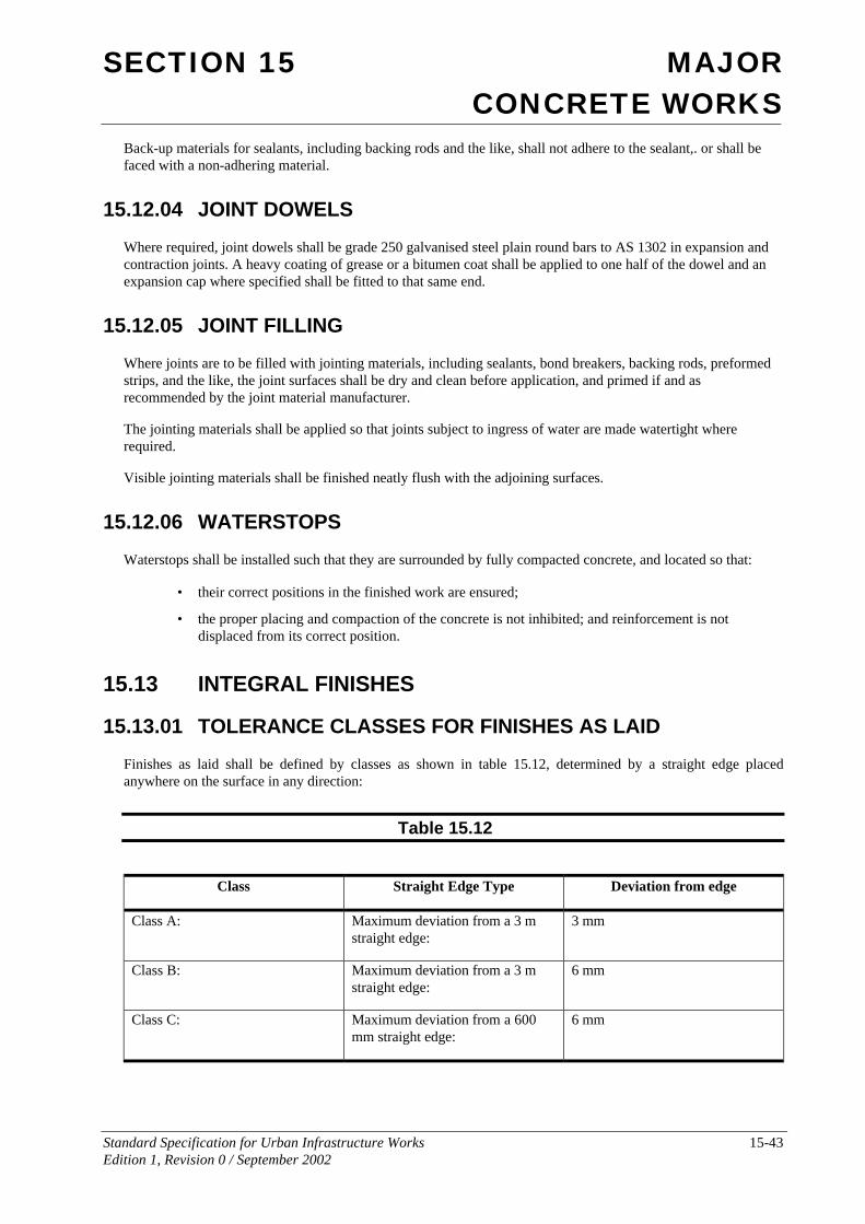
SECTION 15 MAJOR CONCRETE WORKS
Standard Specification for Urban Infrastructure Works 15-43 Edition 1, Revision 0 / September 2002
Back-up materials for sealants, including backing rods and the like, shall not adhere to the sealant,. or shall be faced with a non-adhering material.
15.12.04 JOINT DOWELS
Where required, joint dowels shall be grade 250 galvanised steel plain round bars to AS 1302 in expansion and contraction joints. A heavy coating of grease or a bitumen coat shall be applied to one half of the dowel and an expansion cap where specified shall be fitted to that same end.
15.12.05 JOINT FILLING
Where joints are to be filled with jointing materials, including sealants, bond breakers, backing rods, preformed strips, and the like, the joint surfaces shall be dry and clean before application, and primed if and as recommended by the joint material manufacturer.
The jointing materials shall be applied so that joints subject to ingress of water are made watertight where required.
Visible jointing materials shall be finished neatly flush with the adjoining surfaces.
15.12.06 WATERSTOPS
Waterstops shall be installed such that they are surrounded by fully compacted concrete, and located so that:
• their correct positions in the finished work are ensured;
• the proper placing and compaction of the concrete is not inhibited; and reinforcement is not displaced from its correct position.
15.13 INTEGRAL FINISHES
15.13.01 TOLERANCE CLASSES FOR FINISHES AS LAID
Finishes as laid shall be defined by classes as shown in table 15.12, determined by a straight edge placed anywhere on the surface in any direction:
Table 15.12
Class Straight Edge Type Deviation from edge
Class A: Maximum deviation from a 3 m straight edge:
3 mm
Class B: Maximum deviation from a 3 m straight edge:
6 mm
Class C: Maximum deviation from a 600 mm straight edge:
6 mm
SECTION 15 MAJOR CONCRETE WORKS
Standard Specification for Urban Infrastructure Works 15-44 Edition 1, Revision 0 / September 2002
15.13.02 FINISHES AS LAID
For as laid finishes, the concrete surface shall first be finished by screeding to finished levels (or the appropriate level for a granolithic topping). In the absence of any other requirement the screeded surface shall be finished to surface Class B.
Thereafter one of the following finishes may be applied:
Machine Floated Finish: The screeded surface shall be finished with power driven equipment to a uniform smooth texture, hand floated in locations inaccessible to the machine float.
Steel Trowelled Finish: After screeding, the final finish shall be produced with steel hand trowels, free of trowel marks and uniform in texture and appearance.
Wood Float Finish: After screeding, the final finish shall be produced with a wood float.
Scored Finish: After screeding, the surface shall be given a coarse scored texture in the direction shown on the Drawings, by drawing a scoring tool (broom, hessian belt, stiff brush, rake or the like) across the surface.
Sponge Finish: After machine floating, an even textured sand finish shall be obtained by wiping the surface with a damp sponge.
Granolithic Topping:
Topping mix: 1 part cement, 1 part fine aggregate, one and a half parts coarse aggregate maximum size 5 mm by weight. Water/cement ratio 0.50 maximum. Zero slump.
Topping thickness: Not less than 25 mm.
Monolithic placing: As soon as surface water has disappeared from the newly placed base, the topping mix shall be spread, compacted and floated to the required tolerance class and surface finish.
Unless shown otherwise on the Drawings, unformed surfaces shall receive the finishes specified below:
Bridge deck surfaces to which asphaltic concrete surfacing is to be applied and all other upper surfaces not visible in the completed structure: Scored Finish
Footpaths, concrete pavements, median strips, mowing strips: Wood Float Finish
Kerbs, concrete edging strips, tops of walls and wall drains, parapets and all other upper surfaces visible in the completed structure: Steel Trowelled Finish
15.13.03 RUBBED AND FLOATED FINISHES
A smooth rubbed finish shall be obtained by removing the forms whilst the concrete is green, carrying out the necessary patching immediately, and completing the rubbing not later than the following day. The surface shall be wetted and rubbed with a carborundum or similar abrasive brick until a uniform colour and texture are produced. No cement grout shall be used other than the paste drawn from the green concrete by the rubbing process.
A sand floated finish shall be obtained by removing the forms whilst the concrete is green. The surface shall be wetted and rubbed with a wood float. Fine sand shall be rubbed into the surface until a uniform colour and texture are produced.
SECTION 15 MAJOR CONCRETE WORKS
Standard Specification for Urban Infrastructure Works 15-45 Edition 1, Revision 0 / September 2002
A grout floated finish shall be obtained by removing the forms whilst the concrete is green. The surface shall then be dampened and hessian pads or sponge rubber floats shall be used to spread a slurry consisting of one part cement (including an appropriate percentage of white cement) and one and a half parts sand passing a 1 mm sieve, The surplus shall be removed until a uniform colour and texture are produced. The finished surface shall then be cured.
An exposed aggregate finish shall be achieved by removing the forms whilst the concrete is green. The surface shall then be wetted and scrubbed with stiff fibre or wire brushes, using water freely, until the surface film of mortar is mechanically removed without the use of acid etching, and the aggregate uniformly exposed. The surface shall finally be rinsed with clean water.
15.13.04 SURFACE TREATMENT
If evaluation of formed surface tolerance or colour is required, this evaluation shall be completed prior to surface treatment.
Surface treatments, where specified, shall comply with the following requirements:
Abrasive Blasted Finish: Blast the cured concrete surface with hard, sharp graded abrasive fine aggregate particles until the coarse aggregate is in uniform relief.
Light Abrasive Blasted Finish: Blast the cured surface with hard, sharp graded abrasive fine aggregate particles to provide a uniform matt finish without exposing the coarse aggregate.
Bush Hammered Finish: Remove the minimum matrix by bush hammering to expose the coarse aggregate without recessing the matrix deeper than the aggregate, so as to give a uniform texture with relatively insignificant random tool marks.
15.13.05 SURFACE MODIFIERS
Surface modifiers, where specified, shall comply with the following requirements:
Clear Resin Sealers: An approved transparent acrylic resin sealer, resistant to ultraviolet rays, suitable for exterior or interior applications, rendering the surface impervious to stains of oils, grease, water and acids, non-yellowing, non-discolouring to the base surfaces, cut with a combination of hydrocarbon solvents to give good penetration into the surface. Total solids shall be not less than 14%.
Seal Stripper: A thoroughly clean surface shall be produced before the application of specified finishes to masonry and cementitious floors. Wax (buffable, self-polishing and acrylic paste types), heavy duty polymer finishes, and clear resin sealer shall be removed with an approved seal stripper applied in accordance with the manufacturer's recommendations.
Surface Hardener: An approved type for cementitious toppings or as laid surfaces, applied to clean surfaces and to the manufacturer's recommendations. The surface hardener shall not be applied to non-slip topping.
15.14 SAMPLING AND TESTING The Contractor shall conduct testing and assessment of concrete and concrete materials as specified herein. Unless otherwise specified, testing shall be on a production assessment basis in accordance with AS 3600 Section 20, and AS 1379 Section 6. The frequency of testing shall be as specified in Clause 15.14.06
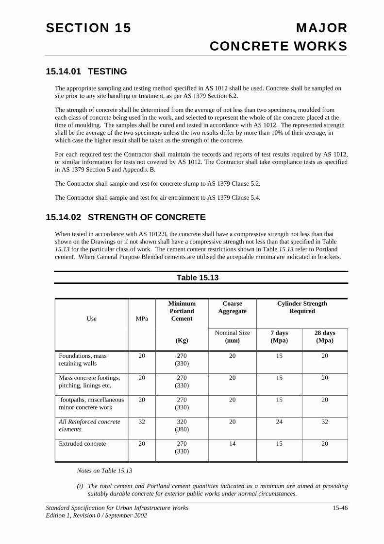
SECTION 15 MAJOR CONCRETE WORKS
Standard Specification for Urban Infrastructure Works 15-46 Edition 1, Revision 0 / September 2002
15.14.01 TESTING
The appropriate sampling and testing method specified in AS 1012 shall be used. Concrete shall be sampled on site prior to any site handling or treatment, as per AS 1379 Section 6.2.
The strength of concrete shall be determined from the average of not less than two specimens, moulded from each class of concrete being used in the work, and selected to represent the whole of the concrete placed at the time of moulding. The samples shall be cured and tested in accordance with AS 1012. The represented strength shall be the average of the two specimens unless the two results differ by more than 10% of their average, in which case the higher result shall be taken as the strength of the concrete.
For each required test the Contractor shall maintain the records and reports of test results required by AS 1012, or similar information for tests not covered by AS 1012. The Contractor shall take compliance tests as specified in AS 1379 Section 5 and Appendix B.
The Contractor shall sample and test for concrete slump to AS 1379 Clause 5.2.
The Contractor shall sample and test for air entrainment to AS 1379 Clause 5.4.
15.14.02 STRENGTH OF CONCRETE
When tested in accordance with AS 1012.9, the concrete shall have a compressive strength not less than that shown on the Drawings or if not shown shall have a compressive strength not less than that specified in Table 15.13 for the particular class of work. The cement content restrictions shown in Table 15.13 refer to Portland cement. Where General Purpose Blended cements are utilised the acceptable minima are indicated in brackets.
Table 15.13
Minimum Portland Cement
Coarse Aggregate
Cylinder Strength Required
Use
MPa
(Kg)
Nominal Size (mm)
7 days (Mpa)
28 days (Mpa)
Foundations, mass retaining walls
20 270 (330)
20 15 20
Mass concrete footings, pitching, linings etc.
20 270 (330)
20 15 20
footpaths, miscellaneous minor concrete work
20 270 (330)
20 15 20
All Reinforced concrete elements.
32 320 (380)
20 24 32
Extruded concrete 20 270 (330)
14 15 20
Notes on Table 15.13
(i) The total cement and Portland cement quantities indicated as a minimum are aimed at providing suitably durable concrete for exterior public works under normal circumstances.
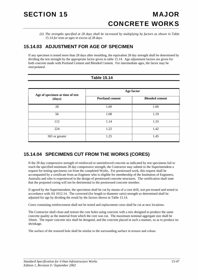
SECTION 15 MAJOR CONCRETE WORKS
Standard Specification for Urban Infrastructure Works 15-47 Edition 1, Revision 0 / September 2002
(ii) The strengths specified at 28 days shall be increased by multiplying by factors as shown in Table 15.14 for tests at ages in excess of 28 days.
15.14.03 ADJUSTMENT FOR AGE OF SPECIMEN
If any specimen is tested more than 28 days after moulding, the equivalent 28 day strength shall be determined by dividing the test strength by the appropriate factor given in table 15.14. Age adjustment factors are given for both concrete made with Portland Cement and Blended Cement. For intermediate ages, the factor may be interpolated.
Table 15.14
Age factor Age of specimen at time of test
(days) Portland cement Blended cement
28 1.00 1.00
56 1.08 1.19
112 1.14 1.33
224 1.22 1.42
365 or greater 1.25 1.45
15.14.04 SPECIMENS CUT FROM THE WORKS (CORES)
If the 28 day compressive strength of reinforced or unreinforced concrete as indicated by test specimens fail to reach the specified minimum 28 day compressive strength, the Contractor may submit to the Superintendent a request for testing specimens cut from the completed Works. For prestressed work, this request shall be accompanied by a certificate from an Engineer who is eligible for membership of the Institution of Engineers, Australia and who is experienced in the design of prestressed concrete structures. The certification shall state that the proposed coring will not be detrimental to the prestressed concrete member.
If agreed by the Superintendent, the specimens shall be cut by means of a core drill, wet pre-treated and tested in accordance with AS 1012.14. The corrected (for length to diameter ratio) strength so determined shall be adjusted for age by dividing the result by the factors shown in Table 15.14.
Cores containing reinforcement shall not be tested and replacement cores shall be cut at new locations.
The Contractor shall clean and restore the core holes using concrete with a mix designed to produce the same concrete quality as the material from which the core was cut. The maximum nominal aggregate size shall be 10mm. The repair concrete mix shall be designed, and the concrete placed in such a manner, so as to produce no shrinkage.
The surface of the restored hole shall be similar to the surrounding surface in texture and colour.
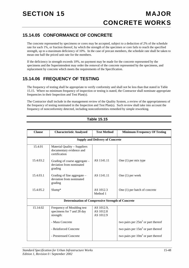
SECTION 15 MAJOR CONCRETE WORKS
Standard Specification for Urban Infrastructure Works 15-48 Edition 1, Revision 0 / September 2002
15.14.05 CONFORMANCE OF CONCRETE
The concrete represented by specimens or cores may be accepted, subject to a deduction of 2% of the schedule rate for each 1%, or fraction thereof, by which the strength of the specimen or core fails to reach the specified strength, up to a maximum deficiency of 10%. In the case of precast members, the schedule rate shall be taken to mean one half the priced unit rate for the members.
If the deficiency in strength exceeds 10%, no payment may be made for the concrete represented by the specimens and the Superintendent may order the removal of the concrete represented by the specimens, and replacement by concrete which meets the requirements of the Specification.
15.14.06 FREQUENCY OF TESTING
The frequency of testing shall be appropriate to verify conformity and shall not be less than that stated in Table 15.15. Where no minimum frequency of inspection or testing is stated, the Contractor shall nominate appropriate frequencies in their Inspection and Test Plan(s).
The Contractor shall include in the management review of the Quality System, a review of the appropriateness of the frequency of testing nominated in the Inspection and Test Plan(s). Such review shall take into account the frequency of nonconformity detected, including nonconformities remedied by simple reworking.
Table 15.15
Clause Characteristic Analysed Test Method Minimum Frequency Of Testing
Supply and Delivery of Concrete
15.4.01
15.4.03.2
Material Quality – Suppliers documentary evidence and certification
Grading of coarse aggregate – deviation from nominated grading
AS 1141.11
One (1) per mix type
15.4.03.1 Grading of fine aggregate – deviation from nominated grading
AS 1141.11 One (1) per week
15.4.05.2 Slump* AS 1012.3 Method 1
One (1) per batch of concrete
Determination of Compressive Strength of Concrete
15.14.02 Frequency of Moulding test specimens for 7 and 28 day strength:
AS 1012.9, AS 1012.8 AS 1012.9
- Mass Concrete two pairs per 25m3 or part thereof
- Reinforced Concrete two pairs per 15m3 or part thereof
- Prestressed Concrete two pairs per 10m3 or part thereof
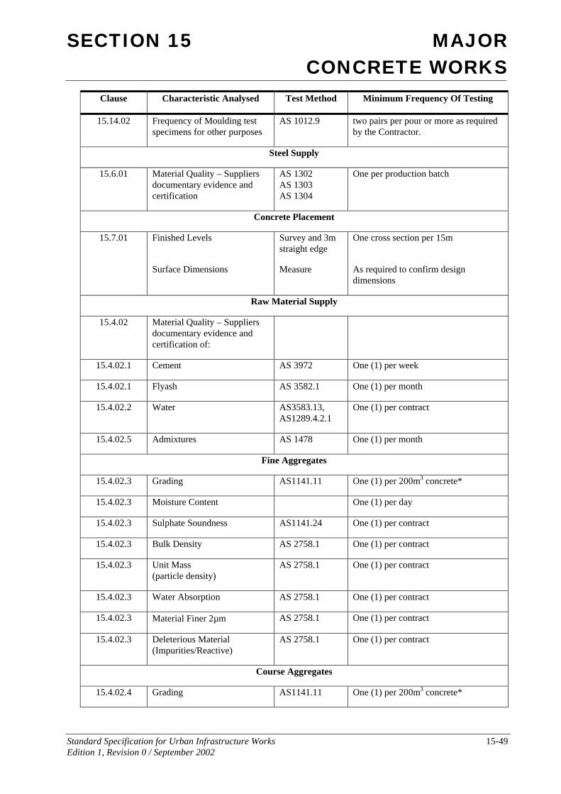
SECTION 15 MAJOR CONCRETE WORKS
Standard Specification for Urban Infrastructure Works 15-49 Edition 1, Revision 0 / September 2002
Clause Characteristic Analysed Test Method Minimum Frequency Of Testing
15.14.02 Frequency of Moulding test specimens for other purposes
AS 1012.9 two pairs per pour or more as required by the Contractor.
Steel Supply
15.6.01 Material Quality – Suppliers documentary evidence and certification
AS 1302 AS 1303 AS 1304
One per production batch
Concrete Placement
15.7.01 Finished Levels
Surface Dimensions
Survey and 3m straight edge
Measure
One cross section per 15m
As required to confirm design dimensions
Raw Material Supply
15.4.02 Material Quality – Suppliers documentary evidence and certification of:
15.4.02.1 Cement AS 3972 One (1) per week
15.4.02.1 Flyash AS 3582.1 One (1) per month
15.4.02.2 Water AS3583.13, AS1289.4.2.1
One (1) per contract
15.4.02.5 Admixtures AS 1478 One (1) per month
Fine Aggregates
15.4.02.3 Grading AS1141.11 One (1) per 200m3 concrete*
15.4.02.3 Moisture Content One (1) per day
15.4.02.3 Sulphate Soundness AS1141.24 One (1) per contract
15.4.02.3 Bulk Density AS 2758.1 One (1) per contract
15.4.02.3 Unit Mass (particle density)
AS 2758.1 One (1) per contract
15.4.02.3 Water Absorption AS 2758.1 One (1) per contract
15.4.02.3 Material Finer 2µm AS 2758.1 One (1) per contract
15.4.02.3 Deleterious Material (Impurities/Reactive)
AS 2758.1 One (1) per contract
Course Aggregates
15.4.02.4 Grading AS1141.11 One (1) per 200m3 concrete*
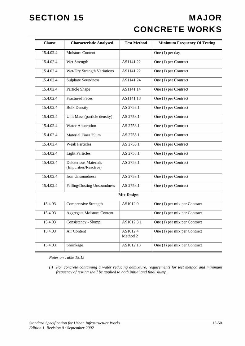
SECTION 15 MAJOR CONCRETE WORKS
Standard Specification for Urban Infrastructure Works 15-50 Edition 1, Revision 0 / September 2002
Clause Characteristic Analysed Test Method Minimum Frequency Of Testing
15.4.02.4 Moisture Content One (1) per day
15.4.02.4 Wet Strength AS1141.22 One (1) per Contract
15.4.02.4 Wet/Dry Strength Variations AS1141.22 One (1) per Contract
15.4.02.4 Sulphate Soundness AS1141.24 One (1) per Contract
15.4.02.4 Particle Shape AS1141.14 One (1) per Contract
15.4.02.4 Fractured Faces AS1141.18 One (1) per Contract
15.4.02.4 Bulk Density AS 2758.1 One (1) per Contract
15.4.02.4 Unit Mass (particle density) AS 2758.1 One (1) per Contract
15.4.02.4 Water Absorption AS 2758.1 One (1) per Contract
15.4.02.4 Material Finer 75µm AS 2758.1 One (1) per Contract
15.4.02.4 Weak Particles AS 2758.1 One (1) per Contract
15.4.02.4 Light Particles AS 2758.1 One (1) per Contract
15.4.02.4 Deleterious Materials (Impurities/Reactive)
AS 2758.1 One (1) per Contract
15.4.02.4 Iron Unsoundness AS 2758.1 One (1) per Contract
15.4.02.4 Falling/Dusting Unsoundness AS 2758.1 One (1) per Contract
Mix Design
15.4.03 Compressive Strength AS1012.9 One (1) per mix per Contract
15.4.03 Aggregate Moisture Content One (1) per mix per Contract
15.4.03 Consistency - Slump AS1012.3.1 One (1) per mix per Contract
15.4.03 Air Content AS1012.4 Method 2
One (1) per mix per Contract
15.4.03 Shrinkage AS1012.13 One (1) per mix per Contract
Notes on Table 15.15
(i) For concrete containing a water reducing admixture, requirements for test method and minimum frequency of testing shall be applied to both initial and final slump.
SECTION 15 MAJOR CONCRETE WORKS
Standard Specification for Urban Infrastructure Works 15-51 Edition 1, Revision 0 / September 2002
15.15 MEASUREMENT AND PAYMENT Payment shall be made for the activities associated with completing the work detailed in this Specification in accordance with the Pay Items 1505P1-P2, 1507P1 and 1511P1 inclusive.
The pay items applicable to particular activities are listed in the Specifications for these activities.
Unless otherwise A lump sum price for any of these items shall not be accepted.
If any item for which a quantity of work is listed in the Contract has not been priced by the Contractor, it shall be understood that due allowance has been made in the prices of other items for the cost of the activity which has not been priced.
The Contractor shall allow in the pay items generally for the costs associated with all testing required to prove conformance of the works as specified.
Pay Item 1505P1 Sprayed Concrete The unit of measurement shall be the square metre of sprayed concrete in place.
This pay item shall include all of the operations involved in the surface preparation, spraying, jointing, supply and placement of reinforcement, removal of splash and rebound material and curing.
1507P1.1 75mm Thick Sprayed Concrete 1507P1.2 100mm Thick Sprayed Concrete 1507P1.3 150mm Thick Sprayed Concrete
Pay Item 1505P2 Concrete Works The unit of measurement shall be the cubic metre of concrete supplied and placed.
This pay item shall include all operations involved in the forming, compaction of concrete, curing, embedments, cores and fixings, jointing and conformance testing.
A separate pay item shall be included in the Contract for each grade of concrete specified.
155P1.1 Grade N20 Concrete 155P1.2 Grade N25 Concrete 155P1.3 Grade N32 Concrete 155P1.4 Grade N40 Concrete
Pay Item 1507P1 Reinforcement The unit of measurement shall be tonnage of reinforcement supplied and placed in the works.
This pay item shall include all operations and materials involved in supply, placement and fixing of reinforcement.
Pay Item 1511P1 Precast Units The unit of measurement shall be per precast unit constructed.
This pay item shall include manufacture, supply of all materials, delivery to site, including loading, unloading and stacking and installation of precast units.
This pay item is not applicable to piles.
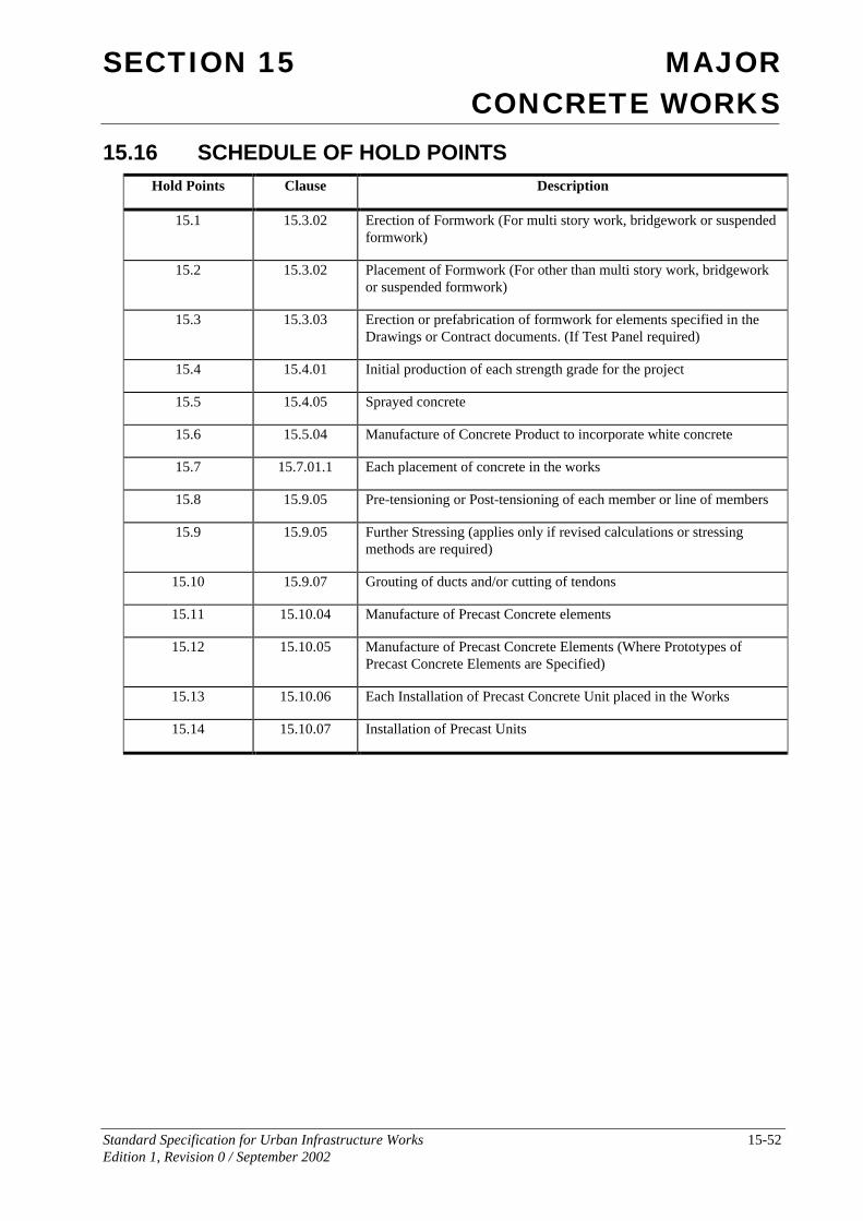
SECTION 15 MAJOR CONCRETE WORKS
Standard Specification for Urban Infrastructure Works 15-52 Edition 1, Revision 0 / September 2002
15.16 SCHEDULE OF HOLD POINTS Hold Points Clause Description
15.1 15.3.02 Erection of Formwork (For multi story work, bridgework or suspended formwork)
15.2 15.3.02 Placement of Formwork (For other than multi story work, bridgework or suspended formwork)
15.3 15.3.03 Erection or prefabrication of formwork for elements specified in the Drawings or Contract documents. (If Test Panel required)
15.4 15.4.01 Initial production of each strength grade for the project
15.5 15.4.05 Sprayed concrete
15.6 15.5.04 Manufacture of Concrete Product to incorporate white concrete
15.7 15.7.01.1 Each placement of concrete in the works
15.8 15.9.05 Pre-tensioning or Post-tensioning of each member or line of members
15.9 15.9.05 Further Stressing (applies only if revised calculations or stressing methods are required)
15.10 15.9.07 Grouting of ducts and/or cutting of tendons
15.11 15.10.04 Manufacture of Precast Concrete elements
15.12 15.10.05 Manufacture of Precast Concrete Elements (Where Prototypes of Precast Concrete Elements are Specified)
15.13 15.10.06 Each Installation of Precast Concrete Unit placed in the Works
15.14 15.10.07 Installation of Precast Units