Embed Size (px)
Citation preview
Section 10 Chapter 13
7-89421NH
24 Valve, 8.3 Liter Engine
Injectors and Fuel Lines
Note: All coding used in the 8.3 Liter and 9 Liter engine manuals are Cummins engine codes. These engine codes have no meaning to New Holland warranty codes and should only be used for procedure
steps.


24 Valve, 8.3 Liter EngineInjectors and Fuel Lines Page a
7-89421NH Section 10 Chapter 13 Issued 8-2001
Injectors and Fuel Lines
Contents
Air in Fuel (006-003)....................................................................................................................................................................................... 3Measure (006-003-010) ................................................................................................................................................................... 3Test (006-003-012) .......................................................................................................................................................................... 3
Fuel Connector (Head Mounted) (006-052) ................................................................................................................................................ 22Inspect for Reuse (006-051-007) ................................................................................................................................................... 22Install (006-052-026) ...................................................................................................................................................................... 22Remove (006-052-002) .................................................................................................................................................................. 22
Fuel Drain Line Restriction (006-012) ........................................................................................................................................................... 5Measure (006-012) ........................................................................................................................................................................... 5
Fuel Drain Lines (006-013) ............................................................................................................................................................................ 6Remove (006-013-002) .................................................................................................................................................................... 6Initial Check (006-013-001) .............................................................................................................................................................. 6Inspect for Reuse (006-013-007) ..................................................................................................................................................... 7Install (006-013-026) ........................................................................................................................................................................ 7
Fuel Filter (Spin-On Type) (006-015) ............................................................................................................................................................ 8Remove (006-015-002) .................................................................................................................................................................... 8Install (006-015-026) ........................................................................................................................................................................ 8
Fuel Filter Head Bracket (006-018) ............................................................................................................................................................. 10Assemble (006-018-025) ................................................................................................................................................................ 11Disassemble (006-018-003) ........................................................................................................................................................... 10Inspect for Reuse (006-018-007) ................................................................................................................................................... 11Install (006-018-026) ...................................................................................................................................................................... 11Remove (006-018-002) .................................................................................................................................................................. 10
Fuel Inlet Restriction (006-020) ................................................................................................................................................................... 12Initial Check (006-024-001) ............................................................................................................................................................ 12
Fuel Pump Air Bleed Line (006-056)............................................................................................................................................................ 23Remove (006-056-002) ................................................................................................................................................................... 23Install (006-056-026) ....................................................................................................................................................................... 24
Fuel Supply Lines (006-024) ........................................................................................................................................................................ 12Initial Check (006-024-001) ............................................................................................................................................................ 12Inspect for Reuse (006-024-007) ................................................................................................................................................... 13Install (006-024-026) ...................................................................................................................................................................... 13Remove (006-024-002) .................................................................................................................................................................. 13

24 Valve, 8.3 Liter EnginePage b Injectors and Fuel Lines
7-89421NH Section 10 Chapter 13 Issued 8-2001
Injector (006-026) ......................................................................................................................................................................................... 13Assemble (006-026-025) ............................................................................................................................................................... 17Clean (006-026-006) ...................................................................................................................................................................... 15Disassemble (006-026-003) ........................................................................................................................................................... 14Inspect (006-026-062) .................................................................................................................................................................... 17Inspect for Reuse (006-026-007) ................................................................................................................................................... 15Install (006-026-026) ...................................................................................................................................................................... 18Measure (006-026-010) ................................................................................................................................................................. 15Remove (006-026-002) .................................................................................................................................................................. 13Test (006-026-012) ........................................................................................................................................................................ 15
Injectors and Fuel Lines - General Information .......................................................................................................................................... 1General Information ......................................................................................................................................................................... 1
Injector Supply Lines (High Pressure) (006-051) ...................................................................................................................................... 19Initial Check (006-051-001) ............................................................................................................................................................ 19Inspect for Reuse (006-051-007) ................................................................................................................................................... 20Install (006-051-026) ...................................................................................................................................................................... 21Remove (006-051-002) .................................................................................................................................................................. 20

24 Valve, 8.3 Liter Engine Injectors and Fuel Lines - General Information Injectors and Fuel Lines Page 1
7-89421NH Section 10 Chapter 13 Issued 8-2001
Injectors and Fuel Lines - General Information
General Information
� WARNING �Fuel is flammable. Keep all cigarettes, flames, pilot lights, arcingequipment, and switches out of the work area and areas sharingventilation to avoid severe personal injury or death when workingon the fuel system.
Injectors used in the 24 Valve, 8.3 Liter engines have hole type noz-zles. High pressure fuel flows into the side of the injector and causesthe needle to lift and fuel to be injected. The clearances in the nozzlebore are extremely small and any sort of dirt or contaminants will causethe injector needle valve to stick. This is why it is important to cleanaround any fuel connection before servicing it. Also, cap or cover anyopen fuel connections before a fuel system repair is performed.
High pressure fuel is supplied to the injector (1) from the fuel pump viaan injector supply line (2) and a fuel connector (3). The end ferrule onthe injector supply line pushes against the fuel connector when the fuelline nut is torqued in the cylinder head. This force provides the sealingpressure between both the injector supply line to the fuel connectorand the connector to the injector.
The torque on this line is critical. If the nut is under torqued, the sur-faces will not seal and a high pressure fuel leak will result. If the nut isover torqued, the connector and injector will deform and also cause ahigh pressure leak. The leak may result in an injector misfire and lowpower.
Always lubricate the threads of the high pressure line nuts with engineoil before tightening. Always make sure the proper torque is used onthe high pressure line nuts.
The fuel connector contains an edge filter that breaks up small contam-inants that enter the fuel system. The edge filter uses the pulsatinghigh pressure to break up most particles so they are small enough topass through the injector.
NOTE: The edge filters are not a substitute for cleaning and coveringall fuel system connections during repair. Edge filters are not a substi-tute for maintaining the recommended engine mounted fuel filter.
24 Valve, 8.3 Liter Engine Injectors and Fuel Lines - General InformationPage 2 Injectors and Fuel Lines
7-89421NH Section 10 Chapter 13 Issued 8-2001
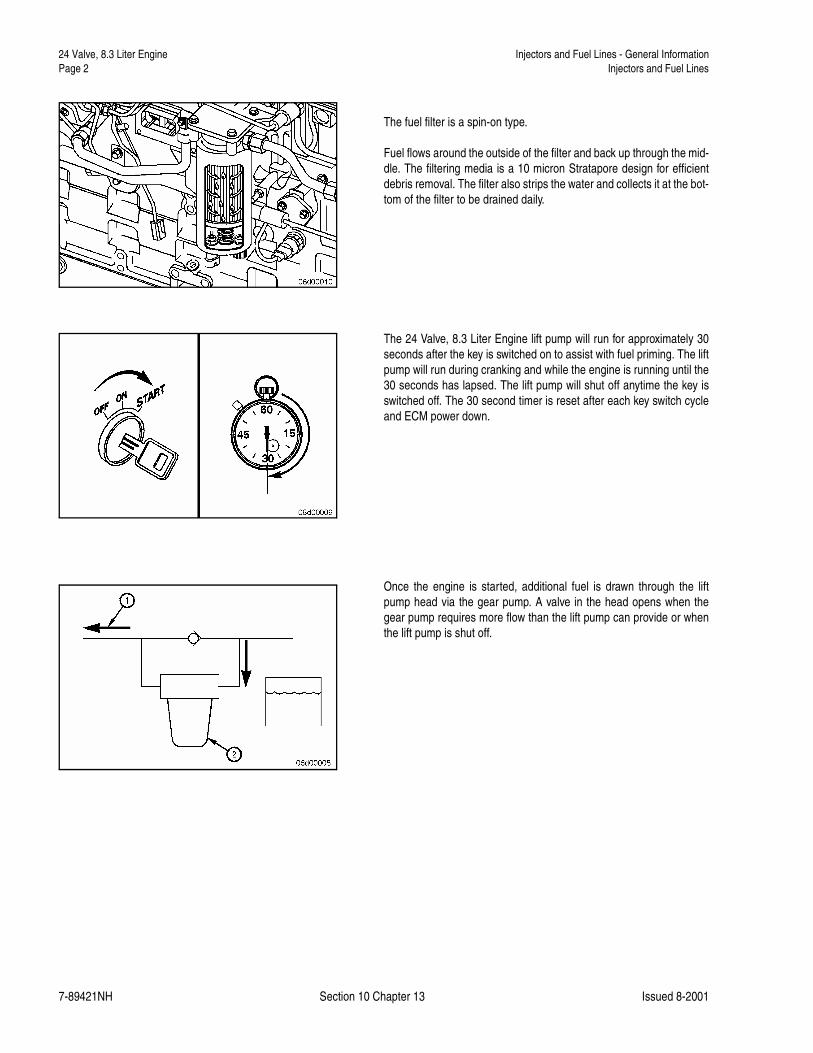
The fuel filter is a spin-on type.
Fuel flows around the outside of the filter and back up through the mid-dle. The filtering media is a 10 micron Stratapore design for efficientdebris removal. The filter also strips the water and collects it at the bot-tom of the filter to be drained daily.
The 24 Valve, 8.3 Liter Engine lift pump will run for approximately 30seconds after the key is switched on to assist with fuel priming. The liftpump will run during cranking and while the engine is running until the30 seconds has lapsed. The lift pump will shut off anytime the key isswitched off. The 30 second timer is reset after each key switch cycleand ECM power down.
Once the engine is started, additional fuel is drawn through the liftpump head via the gear pump. A valve in the head opens when thegear pump requires more flow than the lift pump can provide or whenthe lift pump is shut off.
24 Valve, 8.3 Liter Engine Air in Fuel (006-003) Injectors and Fuel Lines Page 3
7-89421NH Section 10 Chapter 13 Issued 8-2001
Air in Fuel (006-003)
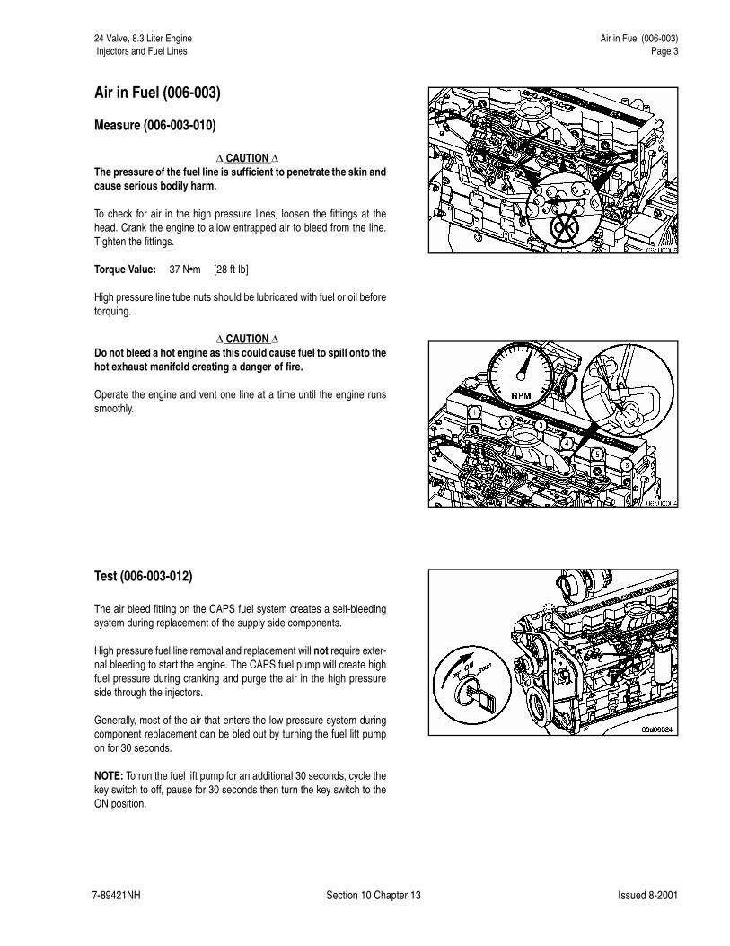
Measure (006-003-010)
� CAUTION �The pressure of the fuel line is sufficient to penetrate the skin andcause serious bodily harm.
To check for air in the high pressure lines, loosen the fittings at thehead. Crank the engine to allow entrapped air to bleed from the line.Tighten the fittings.
Torque Value: 37 N•m [28 ft-lb]
High pressure line tube nuts should be lubricated with fuel or oil beforetorquing.
� CAUTION �Do not bleed a hot engine as this could cause fuel to spill onto thehot exhaust manifold creating a danger of fire.
Operate the engine and vent one line at a time until the engine runssmoothly.
Test (006-003-012)
The air bleed fitting on the CAPS fuel system creates a self-bleedingsystem during replacement of the supply side components.
High pressure fuel line removal and replacement will not require exter-nal bleeding to start the engine. The CAPS fuel pump will create highfuel pressure during cranking and purge the air in the high pressureside through the injectors.
Generally, most of the air that enters the low pressure system duringcomponent replacement can be bled out by turning the fuel lift pumpon for 30 seconds.
NOTE: To run the fuel lift pump for an additional 30 seconds, cycle thekey switch to off, pause for 30 seconds then turn the key switch to theON position.

24 Valve, 8.3 Liter Engine Air in Fuel (006-003)Page 4 Injectors and Fuel Lines
7-89421NH Section 10 Chapter 13 Issued 8-2001
NOTE: If an excessive amount of air has entered the system, the sys-tem will need to be bled.
Loosen the fuel supply line at the CAPS pump. Run the fuel lift pumpuntil the air has been bled. When all the air has been bled, retightenthe fitting.
If air continues to appear in the system for several minutes, an air leakis present. A source, which is often overlooked, for air to enter the fuelsystem is between the inlet of the pre-filter and the suction tube in thetank. Fuel tanks that have the outlet fitting at the top will have a suctiontube at the bottom of the tank. Cracks or pin holes in the weld that joinsthe tube to the fitting can let air enter the fuel system.
Check to make sure that all fittings from the fuel supply line on the tankto the inlet of the fuel lift pump are tight.
Supply line leaks from the lift pump to the CAPS fuel pump may be lo-cated by operating the lift pump via an electronic service tool or keyswitch cycling, to build pressure in the fuel lines. Inspect all lines, con-nections, and filter assembly for an external fuel leak.
19 mm
A stuck open injector can also blow combustion gas back into the pumpand cause air to be present in the overflow. If the engine seems to bemisfiring or running rough, break all the injector supply lines loose atthe pump end. Crank the engine and observe the lines. If combustiongas seems to be blowing back through the line, the injector is stuckopen. Remove and test the injector, refer to Procedure 006-026.
Torque Value: 24 N•m [18 ft-lb]
NOTE: Use two wrenches when loosening the lines at the fuel pump,one to hold the delivery valve and one to loosen the line.
24 Valve, 8.3 Liter Engine Fuel Drain Line Restriction (006-012) Injectors and Fuel Lines Page 5
7-89421NH Section 10 Chapter 13 Issued 8-2001
Fuel Drain Line Restriction (006-012)
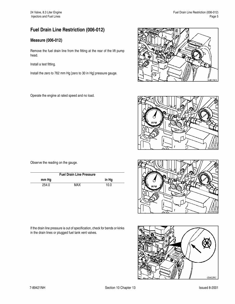
Measure (006-012)
Remove the fuel drain line from the fitting at the rear of the lift pumphead.
Install a test fitting.
Install the zero to 762 mm Hg [zero to 30 in Hg] pressure gauge.
Operate the engine at rated speed and no load.
Observe the reading on the gauge.
If the drain line pressure is out of specification, check for bends or kinksin the drain lines or plugged fuel tank vent valves.
Fuel Drain Line Pressuremm Hg in Hg254.0 MAX 10.0
24 Valve, 8.3 Liter Engine Fuel Drain Lines (006-013)Page 6 Injectors and Fuel Lines
7-89421NH Section 10 Chapter 13 Issued 8-2001
Fuel Drain Lines (006-013)
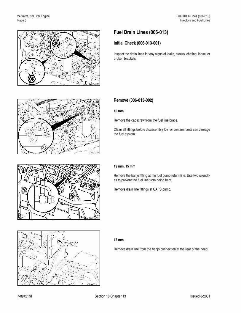
Initial Check (006-013-001)
Inspect the drain lines for any signs of leaks, cracks, chafing, loose, orbroken brackets.
Remove (006-013-002)
10 mm
Remove the capscrew from the fuel line brace.
Clean all fittings before disassembly. Dirt or contaminants can damagethe fuel system.
19 mm, 15 mm
Remove the banjo fitting at the fuel pump return line. Use two wrench-es to prevent the fuel line from being bent.
Remove drain line fittings at CAPS pump.
17 mm
Remove drain line from the banjo connection at the rear of the head.

24 Valve, 8.3 Liter Engine Fuel Drain Lines (006-013) Injectors and Fuel Lines Page 7
7-89421NH Section 10 Chapter 13 Issued 8-2001
17 mm, 19 mm
Disconnect the drain lines from the lift pump.
Inspect for Reuse (006-013-007)
Inspect lines for clogging or a damaged connector.
Install (006-013-026)
19 mm, 15 mm
Connect fuel drain line at fuel pump banjo, rear fitting at the cylinderhead, and lift pump. Use two wrenches when installing the drain line atthe fuel pump return. Use new sealing washers at pump banjo.
Torque Value: 24 N•m [18 ft-lb]
10 mm
Install and tighten the clamp capscrews.
Torque Value: 24 N•m [18 ft-lb]
24 Valve, 8.3 Liter Engine Fuel Filter (Spin-On Type) (006-015)Page 8 Injectors and Fuel Lines
7-89421NH Section 10 Chapter 13 Issued 8-2001
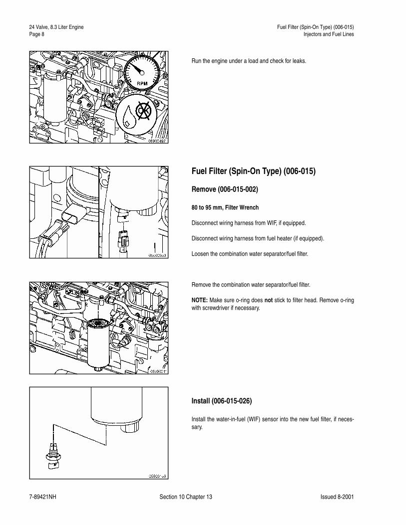
Run the engine under a load and check for leaks.
Fuel Filter (Spin-On Type) (006-015)
Remove (006-015-002)
80 to 95 mm, Filter Wrench
Disconnect wiring harness from WIF, if equipped.
Disconnect wiring harness from fuel heater (if equipped).
Loosen the combination water separator/fuel filter.
Remove the combination water separator/fuel filter.
NOTE: Make sure o-ring does not stick to filter head. Remove o-ringwith screwdriver if necessary.
Install (006-015-026)
Install the water-in-fuel (WIF) sensor into the new fuel filter, if neces-sary.
24 Valve, 8.3 Liter Engine Fuel Filter (Spin-On Type) (006-015) Injectors and Fuel Lines Page 9
7-89421NH Section 10 Chapter 13 Issued 8-2001
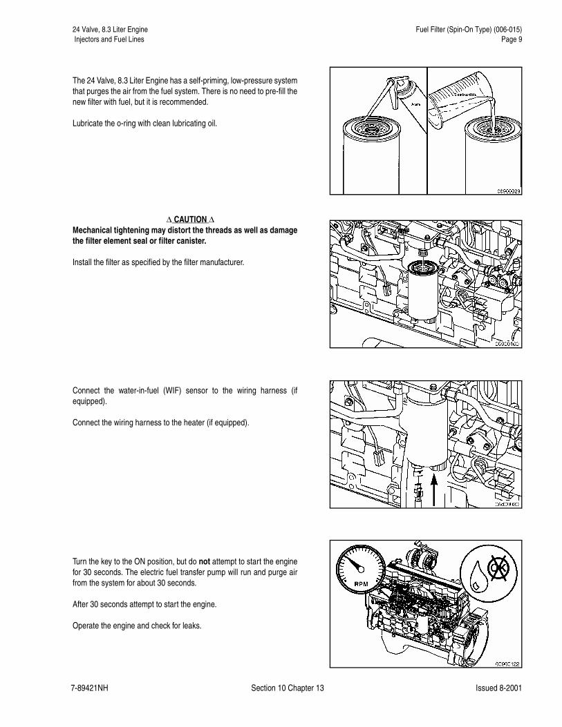
The 24 Valve, 8.3 Liter Engine has a self-priming, low-pressure systemthat purges the air from the fuel system. There is no need to pre-fill thenew filter with fuel, but it is recommended.
Lubricate the o-ring with clean lubricating oil.
� CAUTION �Mechanical tightening may distort the threads as well as damagethe filter element seal or filter canister.
Install the filter as specified by the filter manufacturer.
Connect the water-in-fuel (WIF) sensor to the wiring harness (ifequipped).
Connect the wiring harness to the heater (if equipped).
Turn the key to the ON position, but do not attempt to start the enginefor 30 seconds. The electric fuel transfer pump will run and purge airfrom the system for about 30 seconds.
After 30 seconds attempt to start the engine.
Operate the engine and check for leaks.
24 Valve, 8.3 Liter Engine Fuel Filter Head Bracket (006-018)Page 10 Injectors and Fuel Lines
7-89421NH Section 10 Chapter 13 Issued 8-2001
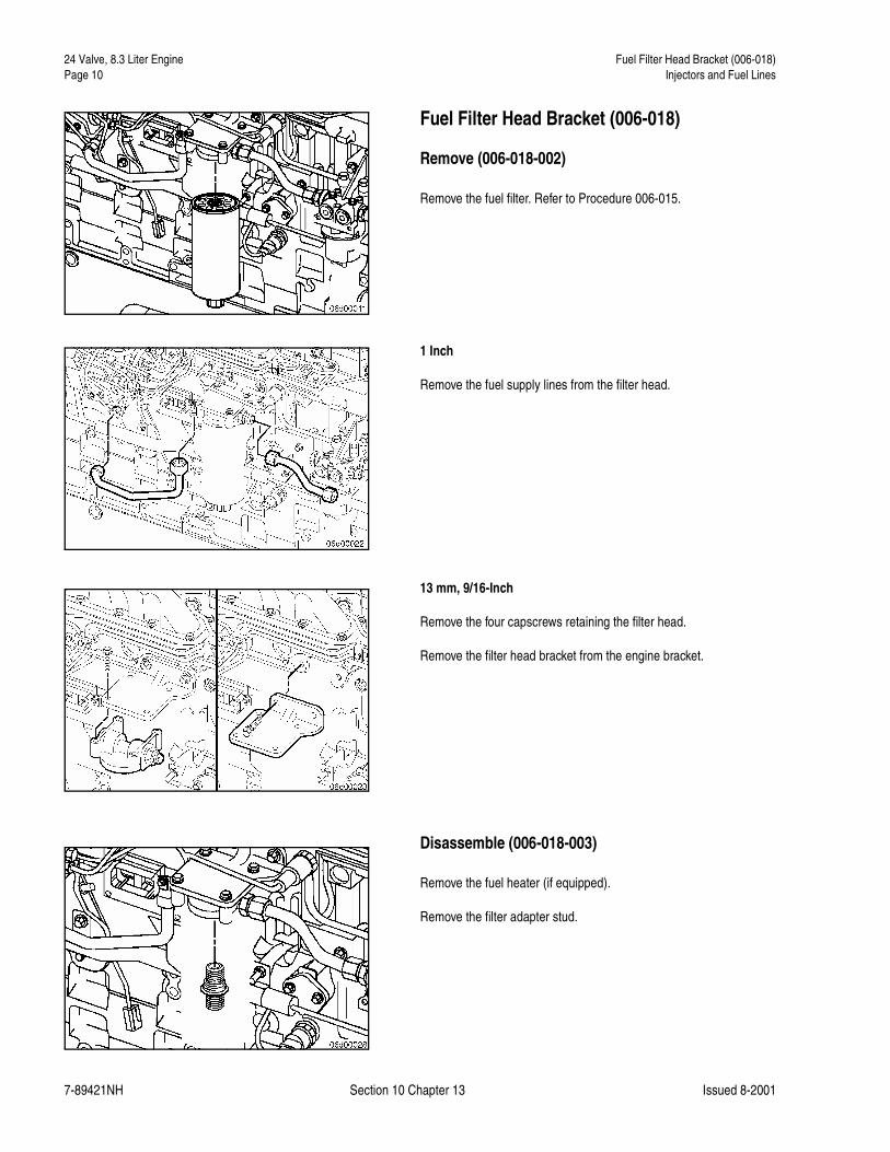
Fuel Filter Head Bracket (006-018)
Remove (006-018-002)
Remove the fuel filter. Refer to Procedure 006-015.
1 Inch
Remove the fuel supply lines from the filter head.
13 mm, 9/16-Inch
Remove the four capscrews retaining the filter head.
Remove the filter head bracket from the engine bracket.
Disassemble (006-018-003)
Remove the fuel heater (if equipped).
Remove the filter adapter stud.

24 Valve, 8.3 Liter Engine Fuel Filter Head Bracket (006-018) Injectors and Fuel Lines Page 11
7-89421NH Section 10 Chapter 13 Issued 8-2001
Inspect for Reuse (006-018-007)
Inspect the filter head for cracks, passage blockage, material or debrison the sealing surfaces.
Assemble (006-018-025)
7/8-Inch
Apply Loctite™ 277, or equivalent, to the filter adapter threads that areengaging the filter head.
Assemble the filter head.
Install the filter adapter and fuel heater (if equipped).
Torque Value: 3.4 N•m [30 in-lb]
NOTE: Make sure there is an o-ring between the filter head and heater.
Install (006-018-026)
14 mm, 9/16-Inch
Install the bracket and filter head. Tighten the retaining capscrews.
Torque Value: 43 N•m [32 ft-lb]
1 Inch
Install fuel lines.
Torque Value: 37 N•m [27 ft-lb]
Install the fuel filter. Refer to Procedure 006-015.

24 Valve, 8.3 Liter Engine Fuel Inlet Restriction (006-020)Page 12 Injectors and Fuel Lines
7-89421NH Section 10 Chapter 13 Issued 8-2001
Run the engine and check for leaks.
Fuel Inlet Restriction (006-020)
Initial Check (006-024-001)
Install a fitting at the lift pump inlet.
Install a vacuum gauge that has a range of at least zero to 508 mm Hg[zero to 20 in Hg].
Measure the inlet restriction.
If the fuel inlet restriction is too high, check to make sure the lines fromthe tank are sized properly, there are no kinks or bends in the lines, andthe lines are not clogged. Also, make sure there are no clogged fuelstrainers or malfunctioning check valves.
Fuel Supply Lines (006-024)
Initial Check (006-024-001)
Inspect all fuel supply line fittings and lines. Look for cracks in the linesor leaking fitting.
Fuel Inlet Restrictionmm Hg in Hg
8 MAX 4

24 Valve, 8.3 Liter Engine Injector (006-026) Injectors and Fuel Lines Page 13
7-89421NH Section 10 Chapter 13 Issued 8-2001
Remove (006-024-002)
1 Inch
Remove fuel supply lines.
Inspect for Reuse (006-024-007)
Look for burrs or debris around the fittings that could cause a leak, alsolook for damaged or frayed flexible fuel hose.
Install (006-024-026)
1 inch
Install fuel supply lines.
Torque Value: 37 N•m [27 ft-lb]
Injector (006-026)
Remove (006-026-002)
Remove the rocker lever cover. Refer to Procedure 003-011.
Remove the injector supply lines. Refer to Procedure 006-051.
The fuel connector must be removed before removing the injector ordamage to the connector will result.

24 Valve, 8.3 Liter Engine Injector (006-026)Page 14 Injectors and Fuel Lines
7-89421NH Section 10 Chapter 13 Issued 8-2001
8 mm
Remove the injector hold-down.
Injector Puller, Tool No. 3825156
Using the injector puller, Tool No. 3825156, pull the injector out of thehead.
Disassemble (006-026-003)
Place the injector in the injector clamp and remove the nozzle retainingnut.
NOTE: Injectors covered under warranty by the manufacturer shouldnot be repaired. Refer to the manufacturer's warranty instructions.
Remove the nozzle, intermediate plate, spring, and shims from the in-jector.
24 Valve, 8.3 Liter Engine Injector (006-026) Injectors and Fuel Lines Page 15
7-89421NH Section 10 Chapter 13 Issued 8-2001
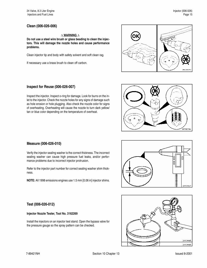
Clean (006-026-006)
� WARNING �Do not use a steel wire brush or glass beading to clean the injec-tors. This will damage the nozzle holes and cause performanceproblems.
Clean injector tip and body with safety solvent and soft clean rag.
If necessary use a brass brush to clean off carbon.
Inspect for Reuse (006-026-007)
Inspect the injector. Inspect o-ring for damage. Look for burrs on the in-let to the injector. Check the nozzle holes for any signs of damage suchas hole erosion or hole plugging. Also check the nozzle color for signsof overheating. Overheating will cause the nozzle to turn dark yellow/tan or blue color depending on the temperature of overheat.
Measure (006-026-010)
Verify the injector sealing washer is the correct thickness. The incorrectsealing washer can cause high pressure fuel leaks, and/or perfor-mance problems due to incorrect injector protrusion.
Refer to the injector part number for correct sealing washer shim thick-ness.
NOTE: All 1998 emissions engines use 1.5 mm [0.06 in] injector shims.
Test (006-026-012)
Injector Nozzle Tester, Tool No. 3162269
Install the injectors on an injector test stand. Open the bypass valve forthe pressure gauge so the spray pattern can be checked.

24 Valve, 8.3 Liter Engine Injector (006-026)Page 16 Injectors and Fuel Lines
7-89421NH Section 10 Chapter 13 Issued 8-2001
Operate the test stand lever quickly several times to check the spraypattern of the injectors. Verify that the correct number of plumes arepresent for the number of holes in the injector. Also pay close attentionto the size and shape of each plume. If possible, compare the spraypattern to that of a new injector with the same assembly number.
NOTE: The injector spray pattern is an excellent indicator of the nozzlehole condition. Check each plume carefully because it is possible thatonly a single hole has been damaged, yet significant performance is-sues may result.
Close the bypass valve for the pressure gauge and operate the teststand lever to check the nozzle opening pressure. There should be agood crisp pop when the nozzle opens and the pressure should bewithin specification for the assembly number.
If the nozzle opening pressure is excessively low and/or the nozzlesprays excessive fuel, the injector needle may be sticking. The needlemay be stuck due to poor lubrication or debris.
Sometimes it is possible to unstick an injector needle by using the in-jector test stand. Open the bypass valve for the pressure gauge andoperate the test stand lever rapidly for 10 to 20 strokes.
Recheck the nozzle opening pressure and spray pattern to see if theinjector has returned to normal operation.
If the injector is still out of specification, replace the injector.
24 Valve, 8.3 Liter Engine Injector (006-026) Injectors and Fuel Lines Page 17
7-89421NH Section 10 Chapter 13 Issued 8-2001
Check the injector for drip and/or excessive leak down. Close the by-pass valve for the pressure gauge and build pressure to within 10 barsof the opening pressure of the nozzle.
A drop of fuel should not form within 15 seconds.
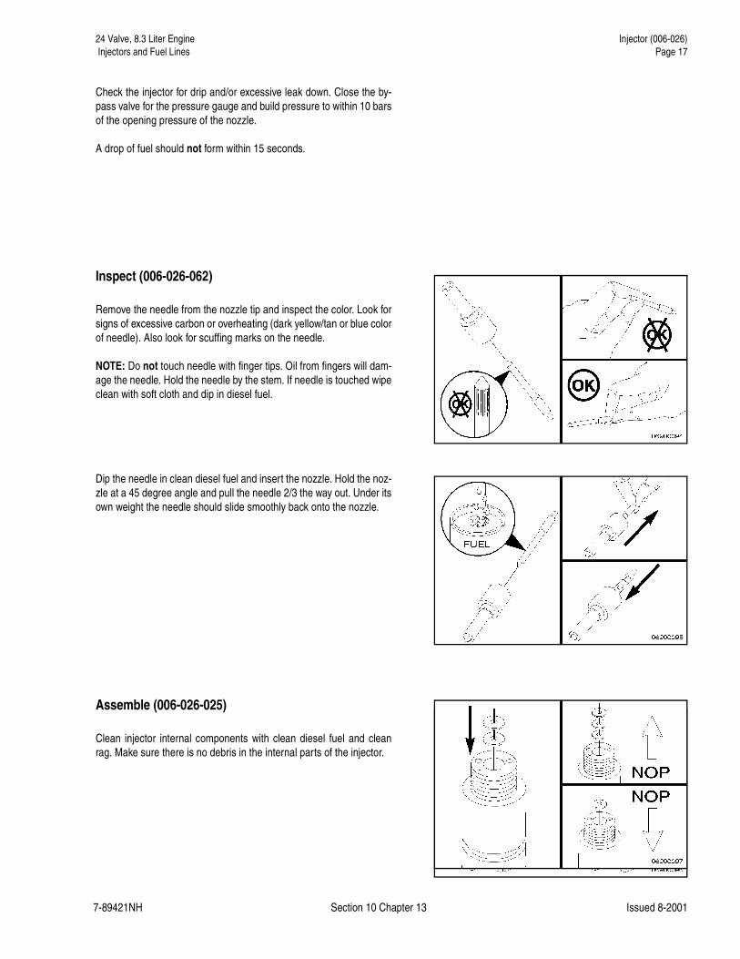
Inspect (006-026-062)
Remove the needle from the nozzle tip and inspect the color. Look forsigns of excessive carbon or overheating (dark yellow/tan or blue colorof needle). Also look for scuffing marks on the needle.
NOTE: Do not touch needle with finger tips. Oil from fingers will dam-age the needle. Hold the needle by the stem. If needle is touched wipeclean with soft cloth and dip in diesel fuel.
Dip the needle in clean diesel fuel and insert the nozzle. Hold the noz-zle at a 45 degree angle and pull the needle 2/3 the way out. Under itsown weight the needle should slide smoothly back onto the nozzle.
Assemble (006-026-025)
Clean injector internal components with clean diesel fuel and cleanrag. Make sure there is no debris in the internal parts of the injector.
24 Valve, 8.3 Liter Engine Injector (006-026)Page 18 Injectors and Fuel Lines
7-89421NH Section 10 Chapter 13 Issued 8-2001
Install shims necessary to modify the nozzle opening pressure. Moreshims raise the nozzle opening pressure, less shims lower the nozzleopening pressure.
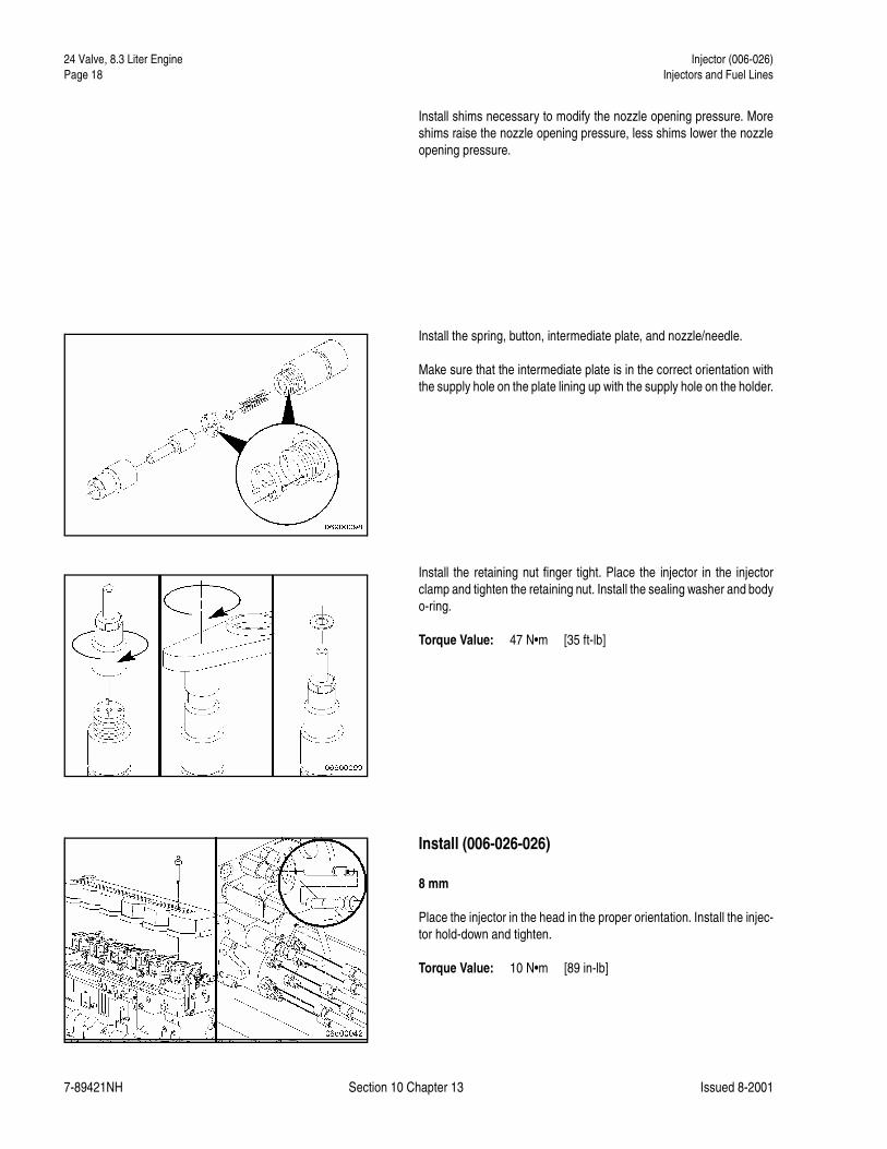
Install the spring, button, intermediate plate, and nozzle/needle.
Make sure that the intermediate plate is in the correct orientation withthe supply hole on the plate lining up with the supply hole on the holder.
Install the retaining nut finger tight. Place the injector in the injectorclamp and tighten the retaining nut. Install the sealing washer and bodyo-ring.
Torque Value: 47 N•m [35 ft-lb]
Install (006-026-026)
8 mm
Place the injector in the head in the proper orientation. Install the injec-tor hold-down and tighten.
Torque Value: 10 N•m [89 in-lb]
24 Valve, 8.3 Liter Engine Injector Supply Lines (High Pressure) (006-051) Injectors and Fuel Lines Page 19
7-89421NH Section 10 Chapter 13 Issued 8-2001
Install the fuel connector. Refer to Procedure 006-052.
Install the rocker lever cover. Refer to Procedure 003-011.
Install the high pressure fuel lines. Refer to Procedure 006-051.
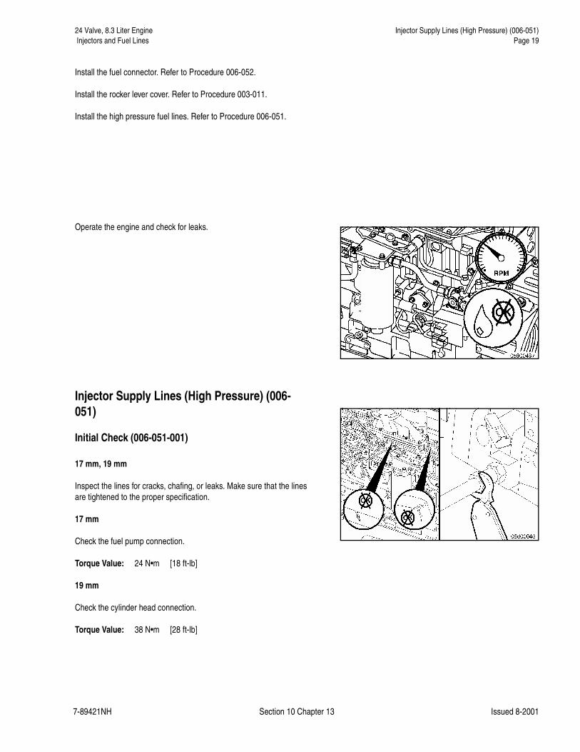
Operate the engine and check for leaks.
Injector Supply Lines (High Pressure) (006-051)
Initial Check (006-051-001)
17 mm, 19 mm
Inspect the lines for cracks, chafing, or leaks. Make sure that the linesare tightened to the proper specification.
17 mm
Check the fuel pump connection.
Torque Value: 24 N•m [18 ft-lb]
19 mm
Check the cylinder head connection.
Torque Value: 38 N•m [28 ft-lb]

24 Valve, 8.3 Liter Engine Injector Supply Lines (High Pressure) (006-051)Page 20 Injectors and Fuel Lines
7-89421NH Section 10 Chapter 13 Issued 8-2001
Remove (006-051-002)
19 mm, 17 mm
Remove the fuel line from the injection pump.
NOTE: Use two wrenches to prevent the outlet fitting from turning.
10 mm
Remove the fuel line clamp capscrews from the intake cover.
Fuel line clamp capscrews must be removed from the intake cover be-fore injection line can be pulled loose from head.
19 mm
Remove the fuel line from the cylinder head.
NOTE: Use two wrenches to prevent the outlet fitting from turning.
Inspect for Reuse (006-051-007)
Check the ferrules of the lines for any signs of burrs or foreign material.
Check for cracks and deformation.

24 Valve, 8.3 Liter Engine Injector Supply Lines (High Pressure) (006-051) Injectors and Fuel Lines Page 21
7-89421NH Section 10 Chapter 13 Issued 8-2001
Install (006-051-026)
Before installing the injector supply lines, make sure that the fuel con-nector is fully and properly seated against the injector.
19 mm, 17 mm
Install the fuel lines in the reverse order of removal.
17 mm
Check the fuel pump connection.
Torque Value: 24 N•m [18 ft-lb]
19 mm
Check the cylinder head connection.
Torque Value: 38 N•m [28 ft-lb]
� WARNING �Do not bleed a hot engine as this could cause fuel to spill onto ahot exhaust manifold creating a danger of fire.
Operate the engine and vent one line at a time until the engine runssmoothly.

24 Valve, 8.3 Liter Engine Fuel Connector (Head Mounted) (006-052)Page 22 Injectors and Fuel Lines
7-89421NH Section 10 Chapter 13 Issued 8-2001
Fuel Connector (Head Mounted) (006-052)
Remove (006-052-002)
Fuel Connector Puller, Tool No. 3825157
Remove injector supply line. Refer to Procedure 006-051.
Install a fuel connector puller, Part No. 3825157.
Remove the fuel connector out of the cylinder head.
NOTE: When removing the fuel connector from the cylinder head, caremust be taken to make sure that the connector o-ring is not damaged.
Inspect for Reuse (006-051-007)
Inspect the fuel connector. Look for burrs or deformation around the in-let and outlet sides of the connector.
Check the edge filter for signs of plugging or material contamination.
Check the o-ring for tearing or deterioration.
NOTE: It is recommended that the o-ring on the high pressure connec-tor is replaced.
Install (006-052-026)
Carefully push the fuel connector into the head until it stops against theinjector. Be sure not to tear the o-ring as the connector is being in-stalled.
NOTE: Lubricate the o-ring prior to installation with the engine or veg-etable oil.
Install high pressure fuel lines. Refer to Procedure 006-051.
Operate engine and check for leaks.

24 Valve, 8.3 Liter Engine Fuel Pump Air Bleed Line (006-056) Injectors and Fuel Lines Page 23
7-89421NH Section 10 Chapter 13 Issued 8-2001
Fuel Pump Air Bleed Line (006-056)
Preparatory (006-056-000)� CAUTION �
Make sure that steam does not spray directly on the electricalconnections on the top of the accumulator block; or fault codeswill possibly occur.
Thoroughly steam-clean the entire fuel pump.
Dry the fuel pump with compressed air
Remove (006-056-002)15 mm, 19 mm
Remove banjo capscrew at the distributor drain fitting of the fuel pump.
Use two wrenches to prevent the line from being bent.
15 mm, 19 mm
Remove the banjo capscrew at the air bleed fitting on top of the fuelpump. It is located on the accumulator module next to the two pumpingcontrol valves.
Use two wrenches to prevent the air bleed fitting from turning.
Inspect for Reuse (006-056-007)
Inspect line for pinches, bends, or damaged connectors.

24 Valve, 8.3 Liter Engine Fuel Pump Air Bleed Line (006-056)Page 24 Injectors and Fuel Lines
7-89421NH Section 10 Chapter 13 Issued 8-2001
Install (006-056-026)
15 mm, 19 mm
Install the banjo capscrew at the air bleed fitting on top of the fuelpump. Use two wrenches to prevent the air bleed fitting from turning.
Torque Value: 8 N�m [70 in-lb]
Use new sealing washers.
15 mm, 19 mm
Install banjo capscrew drain fitting on the fuel pump at the distributor.Use two wrenches to prevent the line from being bent.
Torque Value: 8 N�m [70 in-lb]
Use new sealing washers.
Start the engine and check for fuel leaks at the air bleed line connec-tions.