Embed Size (px)
Citation preview

January 15, 2003 1-1
Section 1Introduction
Note: A variety of game software is compatible with the gaming machine. In addition, gaming machines support many optional components, such as player panel switches, that may affect game play and alter the machine’s physical configuration. Specific procedures and screen displays may vary depending upon the game chip (PROM) configuration and physical configuration of the machine(s).
Note: Specific software features vary depending upon jurisdiction. The information presented in this manual is intended to reflect all features available, but not necessarily those available in any specific jurisdiction.
This manual provides an overview of game software for Vision Series® and S2000™ Series machines. Topics covered include information required to select options, run tests, perform machine diagnostics and record cumulative data.
The information contained in this manual covers both the WAP and non-WAP versions of the software. Refer to the Program Summary Report (PSR) for the specific software version for the specific arrangement of menu items.
IGT field service documentation consists of a series of manuals. Each manual addresses a different aspect of field service and is designed to be used in conjunction with other stand-alone manuals related to:
• Machine specifications
• Game software
• Troubleshooting

Introduction GAME SOFTWARE: VISION SERIES PRODUCTS – RELEASE 9
1-2 January 15, 2003
• Maintenance
• Electronics
• Mechanical parts
Manuals are tailored for product group or, in some cases, product models.
Each manual contains the following information to assist the reader in making the best use of IGT documentation:
• Related IGT Documentation – appears at the back of each manual and lists other books and videotapes that are available.
• Glossary – appears at the back of each book and lists terms and acronyms commonly used in IGT documentation.
• Index – is included at the back of each manual and consists of topics listed alphabetically to assist the reader in finding information quickly and easily.
This manual provides component maintenance instructions for IGT machines. Detailed information about individual machine components is described in separate sections of this manual.
Information in this section includes:
• Section 1.1, Software Overview – summarizes game program software characteristics.
• Section 1.2, Game Operating Modes – describes the various operating modes available in Vision Series machines.
• Section 1.3, Player Information Displays – describes the various information displays present in Vision Series machines.
• Section 1.4, Operator and Attendant Menus – explains the various menu choices available in Vision Series software and identifies access for attendants and operators.
GAME SOFTWARE: VISION SERIES PRODUCTS – RELEASE 9 Introduction
January 15, 2003 1-3
1.1 Software Overview
The Vision Series machine and its accompanying game programs have the following characteristics:
• Operational modes – game play, idle, game play, menu, tilt and out of service
• Player panel switches – illuminate when their function is relevant during game play, testing and diagnostics
• Software-enabled options – game speed, visual and/or attract modes, sound volume, and background color
• Game options – on-screen viewing of accounting, diagnostics, play history, event logs, modify meters, setup, game tests, and out of service
• Key chip feature – prevents unauthorized changes to sensitive options such as denomination and game selection
• Built-in diagnostic capabilities – automatic software review and technician-controlled diagnostic steps that allow the testing of player switches, hopper, coin acceptor, bill acceptor, access door switches, sound effects, and voucher printer
• Test routines for quick diagnostics and problem resolution
Entering the Operator and Attendant Menus
Turn the reset key while the machine is idle with no coins bet to enter the Attendant menu. The machine cannot be in a tilt condition.
To enter the Operator menu, open the machine door and press the operator switch located on the processor tray while the machine is in idle mode.
Menu Navigation
Use the following player panel switches to navigate through the menus:
• CHANGE to move up
• CASH OUT to move down
• SPIN REELS to enter a test or menu
• BET MAX to exit
Introduction GAME SOFTWARE: VISION SERIES PRODUCTS – RELEASE 9
1-4 January 15, 2003
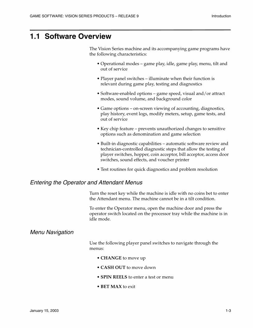
The applicable player panel switches are illuminated during menu and test execution. If the machine has an LCD, player panel switches are also noted on the screen. See Figure 1-1 for an illustration of the correlation between the screen display and the player panel.
Note: The 5-button panel is shown in the following figure. However, the corresponding player panel switches perform the same functions on all switch panel configurations.
Figure 1-1. Player Panel Switch Functions.
Accounting
History
Options
I/O Tests
Game Tests
Service
Key Chip
UP DOWN ENTER EXIT
CHANGE CASHOUT
BETONE
CREDIT
SPINREELS
PLAY3
CREDITS
Setups
00000036-111700

GAME SOFTWARE: VISION SERIES PRODUCTS – RELEASE 9 Introduction
January 15, 2003 1-5
Display of Meter Data
All meters are right or decimal justified. Linear meters may be up to 10 digits with a maximum value of 1,000,000,000. Monetary meters are displayed in number of lowest usable monetary units in the correct format for that currency. Meters in percentage format (100.00%) may be up to 5 digits.
Program Summary Reports (PSRs)
Information about any diagnostic or set-up option not documented in this manual may be obtained by requesting a copy of the program summary report (PSR) for a specific game version. PSRs may be obtained from IGT’s Web Site listed in the front section of this manual, or from IGT Customer Service.

Introduction GAME SOFTWARE: VISION SERIES PRODUCTS – RELEASE 9
1-6 January 15, 2003
1.2 Game Operating Modes
Vision Series game software has five operating modes:
• Game Play Mode – the game is functioning properly and a player is actively playing the game
• Idle Mode – the machine is functioning properly but is not actively being played
• Menu Mode – diagnostic/setup mode that allows an attendant or technician to examine statistical data, check and change settings or options, enter setup and option information, validate and verify previous game outcomes, and/or exercise the machine hardware to either verify proper operation or isolate a problem
• Tilt Mode – a machine malfunction has occurred, such as a sequence error or a coin-in tilt, and game play is locked up until a technician checks the machine
• Out of Service/Reserved Mode – used by a technician to suspend machine operation for the purpose of conducting a repair, to suspend game play for special events, or to reserve a machine for a player

GAME SOFTWARE: VISION SERIES PRODUCTS – RELEASE 9 Introduction
January 15, 2003 1-7
1.3 Player Information Displays
Vision Series and S2000 machines use a variety of displays to communicate information to players and operators (see Figure 1-2). Seven-segment digital LED displays and a vacuum fluorescent alphanumeric display are always present in the machine. Optional displays include a liquid crystal display (LCD) in the top box and a candle.
Note: The following figure shows the display locations for the 5-button player panel. The location of the displays varies by game type as well as player panel configuration.
Figure 1-2. Reel Glass Information Displays.
VACUUM FLUORESCENTDISPLAY
CREDITSPLAYED
CREDITSWINNERPAID
VACUUM FLUORESCENTDISPLAY
CREDITSPLAYED
CREDITSWINNERPAID
UPRIGHT MACHINE
SLANT-TOP MACHINE
00000037-111700
Introduction GAME SOFTWARE: VISION SERIES PRODUCTS – RELEASE 9
1-8 January 15, 2003
Seven-Segment Displays
Seven-segment digital displays located behind the reel glass show coins played, credits and winner paid amounts.
See Figure 1-2 for the locations of all the displays on the reel glass of spinning reel machines.
Vacuum Fluorescent Display (VFD)
The fluorescent dot matrix display on the reel glass (see Figure 1-2) indicates various alphanumeric game messages, player prompts, tilt messages, menu choices, operator and technician-requested information, hand pay messages, and bonus game coin amounts.
Candle
The optional IGT candle located on the top of the machine enclosure indicates various modes or game conditions when the machine power is on.
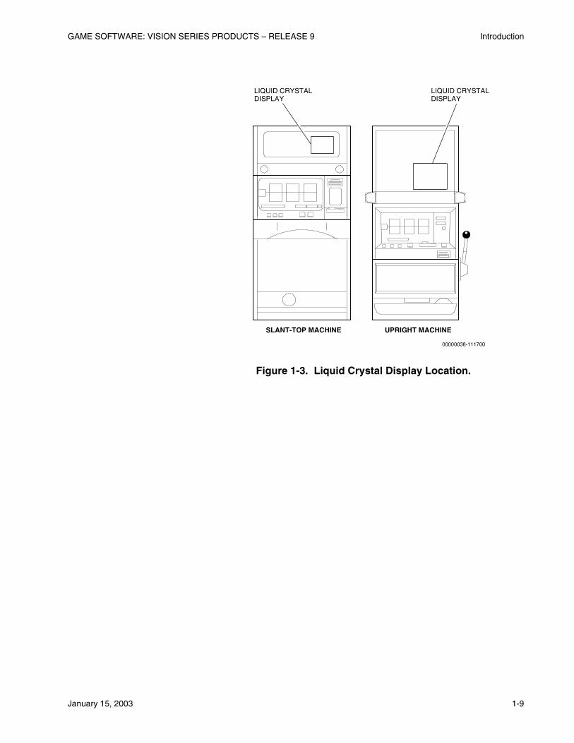
Liquid Crystal Display (LCD)/M-Slave
The optional liquid crystal display (also known as the multi-slave or M-slave) located in the top box is a device that receives signals from the processor for display. The following items are displayed:
• Animated bonus game graphics
• Technician software menu trees
• Service messages
• Diagnostic flag signals
Note: The LCD/M-Slave is not an interactive, touchscreen device, and should never be touched.
See Figure 1-3 for the location of the LCD in upright Vision Series machines.
GAME SOFTWARE: VISION SERIES PRODUCTS – RELEASE 9 Introduction
January 15, 2003 1-9
Figure 1-3. Liquid Crystal Display Location.
LIQUID CRYSTALDISPLAY
LIQUID CRYSTALDISPLAY
SLANT-TOP MACHINE UPRIGHT MACHINE
00000038-111700
Introduction GAME SOFTWARE: VISION SERIES PRODUCTS – RELEASE 9
1-10 January 15, 2003
1.4 Operator and Attendant Menus
An operator is the machine operator, service technician or any other person with access to the interior of the machine.
The attendant has access to machine information by turning the reset key on the outside of the machine. The attendant does not have access to the interior of the machine.
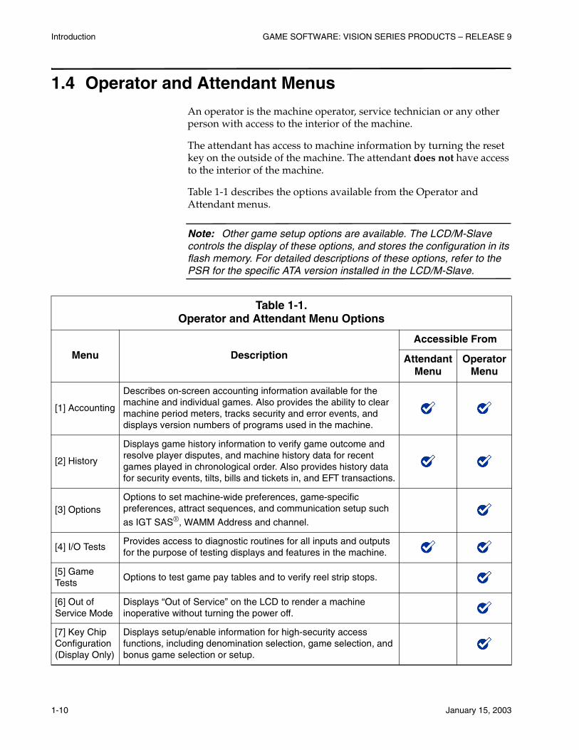
Table 1-1 describes the options available from the Operator and Attendant menus.
Note: Other game setup options are available. The LCD/M-Slave controls the display of these options, and stores the configuration in its flash memory. For detailed descriptions of these options, refer to the PSR for the specific ATA version installed in the LCD/M-Slave.
Table 1-1. Operator and Attendant Menu Options
Menu Description
Accessible From
Attendant Menu
Operator Menu
[1] Accounting
Describes on-screen accounting information available for the machine and individual games. Also provides the ability to clear machine period meters, tracks security and error events, and displays version numbers of programs used in the machine.
[2] History
Displays game history information to verify game outcome and resolve player disputes, and machine history data for recent games played in chronological order. Also provides history data for security events, tilts, bills and tickets in, and EFT transactions.
[3] OptionsOptions to set machine-wide preferences, game-specific preferences, attract sequences, and communication setup such
as IGT SAS®, WAMM Address and channel.
[4] I/O TestsProvides access to diagnostic routines for all inputs and outputs for the purpose of testing displays and features in the machine.
[5] Game Tests
Options to test game pay tables and to verify reel strip stops.
[6] Out of Service Mode
Displays “Out of Service” on the LCD to render a machine inoperative without turning the power off.
[7] Key Chip Configuration (Display Only)
Displays setup/enable information for high-security access functions, including denomination selection, game selection, and bonus game selection or setup.
January 15, 2003 2-1
Section 2Operator and Attendant Menus
This section describes the menus, displays and setup screens available from the Vision Series software Operator and Attendant menus.
Note: Specific software features vary depending upon jurisdiction. The information presented in this manual is intended to reflect all features available, but not necessarily those available in any specific jurisdiction.
Information in this section includes:
• Section 2.1, Operator and Attendant Menu Options – explains all options and menus in the Operator and Attendant menus.
• Section 2.2, Accounting Menu (Option: [1]) – lists the available menus and options on the Accounting menu.
• Section 2.3, History Displays (Option: [2]) – lists the screens available on the History menu.
• Section 2.4, Options Menu (Option: [3]) – lists the menus and options available on the Options menu.
• Section 2.5, I/O Tests (Option: [4]) – lists the menus and options available on the I/O Tests menu.
• Section 2.6, Game Tests (Option: [5]) – lists the menus and options available on the Game Tests menu.
• Section 2.7, Out of Service Mode (Option: [6]) – explains the Out of Service option.
Operator and Attendant Menus GAME SOFTWARE: VISION SERIES PRODUCTS – RELEASE 9
2-2 January 15, 2003
2.1 Operator and Attendant Menu Options
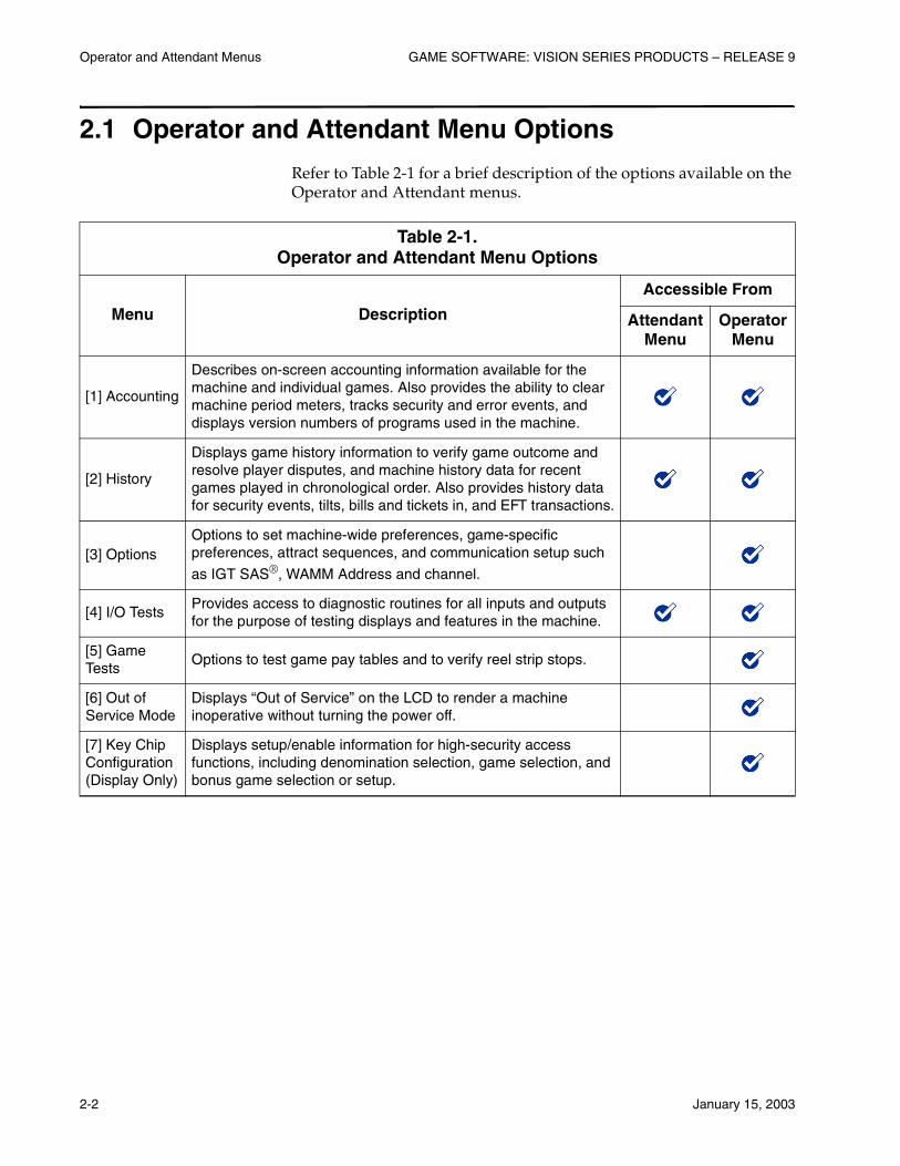
Refer to Table 2-1 for a brief description of the options available on the Operator and Attendant menus.
Table 2-1. Operator and Attendant Menu Options
Menu Description
Accessible From
Attendant Menu
Operator Menu
[1] Accounting
Describes on-screen accounting information available for the machine and individual games. Also provides the ability to clear machine period meters, tracks security and error events, and displays version numbers of programs used in the machine.
[2] History
Displays game history information to verify game outcome and resolve player disputes, and machine history data for recent games played in chronological order. Also provides history data for security events, tilts, bills and tickets in, and EFT transactions.
[3] OptionsOptions to set machine-wide preferences, game-specific preferences, attract sequences, and communication setup such
as IGT SAS®, WAMM Address and channel.
[4] I/O TestsProvides access to diagnostic routines for all inputs and outputs for the purpose of testing displays and features in the machine.
[5] Game Tests
Options to test game pay tables and to verify reel strip stops.
[6] Out of Service Mode
Displays “Out of Service” on the LCD to render a machine inoperative without turning the power off.
[7] Key Chip Configuration (Display Only)
Displays setup/enable information for high-security access functions, including denomination selection, game selection, and bonus game selection or setup.
GAME SOFTWARE: VISION SERIES PRODUCTS – RELEASE 9 Operator and Attendant Menus
January 15, 2003 2-3
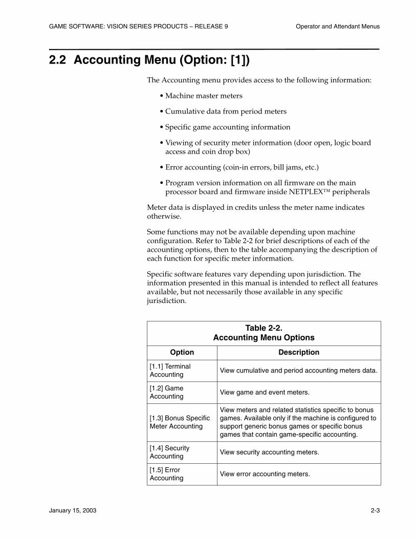
2.2 Accounting Menu (Option: [1])
The Accounting menu provides access to the following information:
• Machine master meters
• Cumulative data from period meters
• Specific game accounting information
• Viewing of security meter information (door open, logic board access and coin drop box)
• Error accounting (coin-in errors, bill jams, etc.)
• Program version information on all firmware on the main processor board and firmware inside NETPLEX™ peripherals
Meter data is displayed in credits unless the meter name indicates otherwise.
Some functions may not be available depending upon machine configuration. Refer to Table 2-2 for brief descriptions of each of the accounting options, then to the table accompanying the description of each function for specific meter information.
Specific software features vary depending upon jurisdiction. The information presented in this manual is intended to reflect all features available, but not necessarily those available in any specific jurisdiction.
Table 2-2. Accounting Menu Options
Option Description
[1.1] Terminal Accounting
View cumulative and period accounting meters data.
[1.2] Game Accounting
View game and event meters.
[1.3] Bonus Specific Meter Accounting
View meters and related statistics specific to bonus games. Available only if the machine is configured to support generic bonus games or specific bonus games that contain game-specific accounting.
[1.4] Security Accounting
View security accounting meters.
[1.5] Error Accounting
View error accounting meters.

Operator and Attendant Menus GAME SOFTWARE: VISION SERIES PRODUCTS – RELEASE 9
2-4 January 15, 2003
2.2.1 Terminal Accounting (Option: [1.1])
The Terminal Accounting menu provides access to cumulative and period meter data.
Terminal Master Accounting (Option: [1.1.1])
Terminal Master Money Accounting (Option: [1.1.1.1])
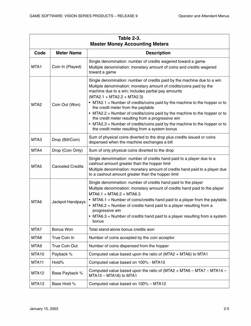
Select the Master Money Accounting option to view meters required to balance the machine and verify that its payback and hold percentages match their theoretical values. Refer to Table 2-3 for a summary of the meter information displayed.
[1.6] Version Accounting
Display version information of both machine and peripheral software.
[1.7] Master Progressive Accounting/General Progressive Accounting
View master progressive accounting meters. View general progressive accounting meters for WAP machines.
[1.8] WAMM Accounting
View accounting information on meters sent to a WAMM COMM in response to a meter poll.
[1.9] PSAMS Accounting
View terminal and game accounting information for machines using the Progressive Security and Accounting Management System (PSAMS). This option is not available on all machines.
Table 2-2. (cont’d)Accounting Menu Options
Option Description
GAME SOFTWARE: VISION SERIES PRODUCTS – RELEASE 9 Operator and Attendant Menus
January 15, 2003 2-5
Table 2-3. Master Money Accounting Meters
Code Meter Name Description
MTA1 Coin In (Played)Single denomination: number of credits wagered toward a gameMultiple denomination: monetary amount of coins and credits wagered toward a game
MTA2 Coin Out (Won)
Single denomination: number of credits paid by the machine due to a winMultiple denomination: monetary amount of credits/coins paid by the machine due to a win; includes partial pay amounts(MTA2.1 + MTA2.2 + MTA2.3)• MTA2.1 = Number of credits/coins paid by the machine to the hopper or to
the credit meter from the paytable• MTA2.2 = Number of credits/coins paid by the machine to the hopper or to
the credit meter resulting from a progressive win• MTA2.3 = Number of credits/coins paid by the machine to the hopper or to
the credit meter resulting from a system bonus
MTA3 Drop (Bill/Coin)Sum of physical coins diverted to the drop plus credits issued or coins dispensed when the machine exchanges a bill
MTA4 Drop (Coin Only) Sum of only physical coins diverted to the drop
MTA5 Canceled Credits
Single denomination: number of credits hand paid to a player due to a cashout amount greater than the hopper limitMultiple denomination: monetary amount of credits hand paid to a player due to a cashout amount greater than the hopper limit
MTA6 Jackpot Handpays
Single denomination: number of credits hand paid to the playerMultiple denomination: monetary amount of credits hand paid to the playerMTA6.1 + MTA6.2 + MTA6.3• MTA6.1 = Number of coins/credits hand paid to a player from the paytable.• MTA6.2 = Number of credits hand paid to a player resulting from a
progressive win• MTA6.3 = Number of credits hand paid to a player resulting from a system
bonus
MTA7 Bonus Won Total stand-alone bonus credits won
MTA8 True Coin In Number of coins accepted by the coin acceptor
MTA9 True Coin Out Number of coins dispensed from the hopper
MTA10 Payback % Computed value based upon the ratio of (MTA2 + MTA6) to MTA1
MTA11 Hold% Computed value based on 100% - MTA10
MTA12 Base Payback %Computed value based upon the ratio of (MTA2 + MTA6 – MTA7 – MTA14 – MTA15 – MTA16) to MTA1
MTA13 Base Hold % Computed value based on 100% – MTA12
Operator and Attendant Menus GAME SOFTWARE: VISION SERIES PRODUCTS – RELEASE 9
2-6 January 15, 2003
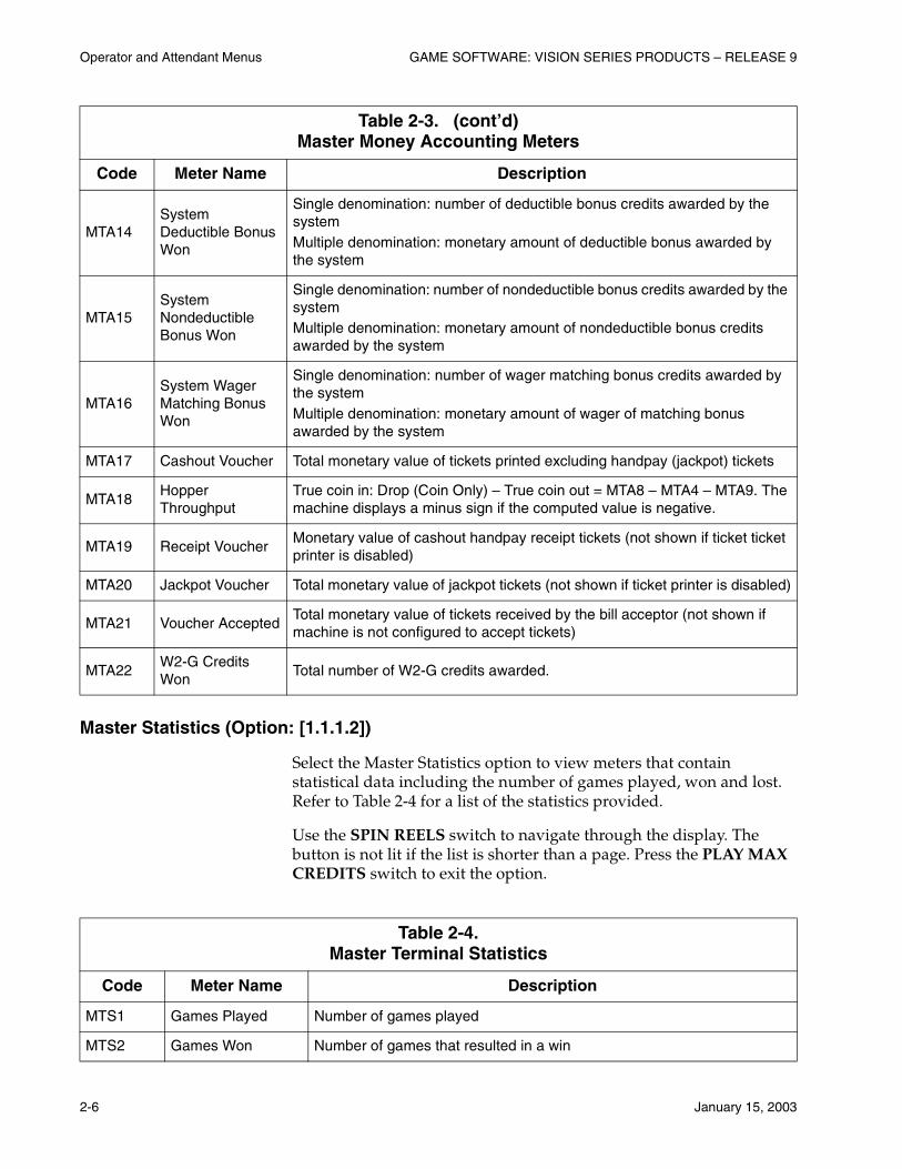
Master Statistics (Option: [1.1.1.2])
Select the Master Statistics option to view meters that contain statistical data including the number of games played, won and lost. Refer to Table 2-4 for a list of the statistics provided.
Use the SPIN REELS switch to navigate through the display. The button is not lit if the list is shorter than a page. Press the PLAY MAX CREDITS switch to exit the option.
MTA14System Deductible Bonus Won
Single denomination: number of deductible bonus credits awarded by the systemMultiple denomination: monetary amount of deductible bonus awarded by the system
MTA15System Nondeductible Bonus Won
Single denomination: number of nondeductible bonus credits awarded by the systemMultiple denomination: monetary amount of nondeductible bonus credits awarded by the system
MTA16System Wager Matching Bonus Won
Single denomination: number of wager matching bonus credits awarded by the systemMultiple denomination: monetary amount of wager of matching bonus awarded by the system
MTA17 Cashout Voucher Total monetary value of tickets printed excluding handpay (jackpot) tickets
MTA18Hopper Throughput
True coin in: Drop (Coin Only) – True coin out = MTA8 – MTA4 – MTA9. The machine displays a minus sign if the computed value is negative.
MTA19 Receipt VoucherMonetary value of cashout handpay receipt tickets (not shown if ticket ticket printer is disabled)
MTA20 Jackpot Voucher Total monetary value of jackpot tickets (not shown if ticket printer is disabled)
MTA21 Voucher AcceptedTotal monetary value of tickets received by the bill acceptor (not shown if machine is not configured to accept tickets)
MTA22W2-G Credits Won
Total number of W2-G credits awarded.
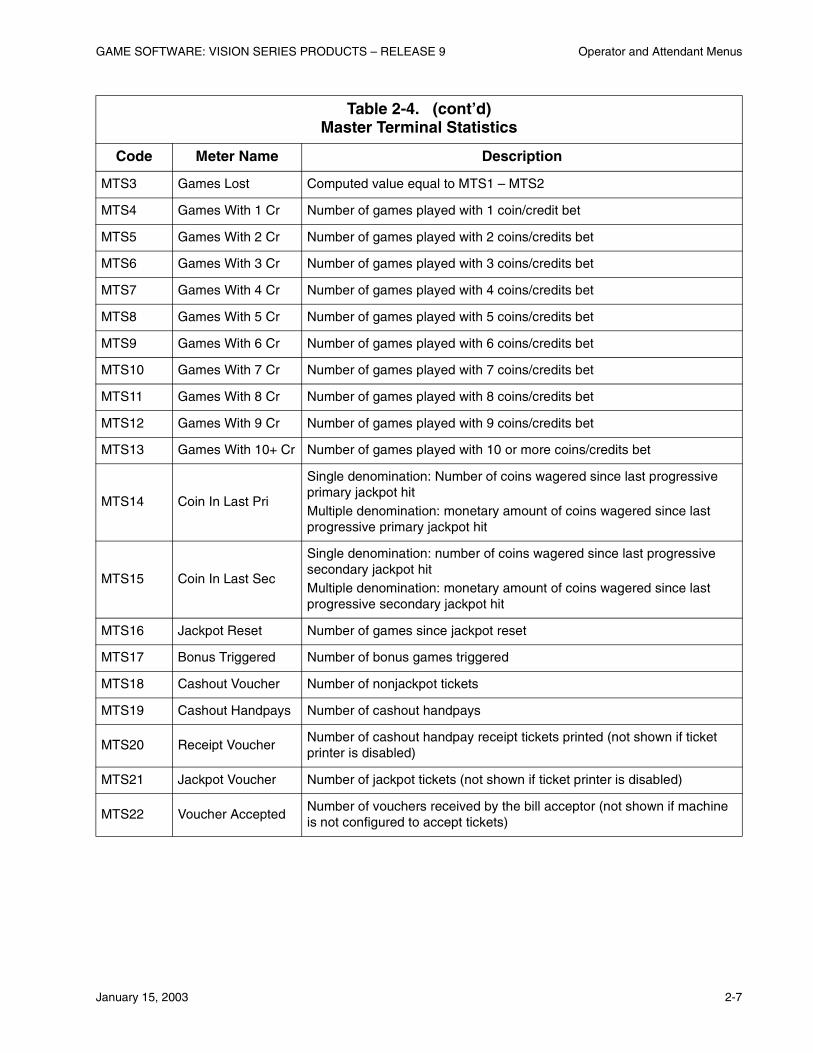
Table 2-4. Master Terminal Statistics
Code Meter Name Description
MTS1 Games Played Number of games played
MTS2 Games Won Number of games that resulted in a win
Table 2-3. (cont’d)Master Money Accounting Meters
Code Meter Name Description
GAME SOFTWARE: VISION SERIES PRODUCTS – RELEASE 9 Operator and Attendant Menus
January 15, 2003 2-7
MTS3 Games Lost Computed value equal to MTS1 – MTS2
MTS4 Games With 1 Cr Number of games played with 1 coin/credit bet
MTS5 Games With 2 Cr Number of games played with 2 coins/credits bet
MTS6 Games With 3 Cr Number of games played with 3 coins/credits bet
MTS7 Games With 4 Cr Number of games played with 4 coins/credits bet
MTS8 Games With 5 Cr Number of games played with 5 coins/credits bet
MTS9 Games With 6 Cr Number of games played with 6 coins/credits bet
MTS10 Games With 7 Cr Number of games played with 7 coins/credits bet
MTS11 Games With 8 Cr Number of games played with 8 coins/credits bet
MTS12 Games With 9 Cr Number of games played with 9 coins/credits bet
MTS13 Games With 10+ Cr Number of games played with 10 or more coins/credits bet
MTS14 Coin In Last Pri
Single denomination: Number of coins wagered since last progressive primary jackpot hitMultiple denomination: monetary amount of coins wagered since last progressive primary jackpot hit
MTS15 Coin In Last Sec
Single denomination: number of coins wagered since last progressive secondary jackpot hitMultiple denomination: monetary amount of coins wagered since last progressive secondary jackpot hit
MTS16 Jackpot Reset Number of games since jackpot reset
MTS17 Bonus Triggered Number of bonus games triggered
MTS18 Cashout Voucher Number of nonjackpot tickets
MTS19 Cashout Handpays Number of cashout handpays
MTS20 Receipt VoucherNumber of cashout handpay receipt tickets printed (not shown if ticket printer is disabled)
MTS21 Jackpot Voucher Number of jackpot tickets (not shown if ticket printer is disabled)
MTS22 Voucher AcceptedNumber of vouchers received by the bill acceptor (not shown if machine is not configured to accept tickets)
Table 2-4. (cont’d)Master Terminal Statistics
Code Meter Name Description

Operator and Attendant Menus GAME SOFTWARE: VISION SERIES PRODUCTS – RELEASE 9
2-8 January 15, 2003
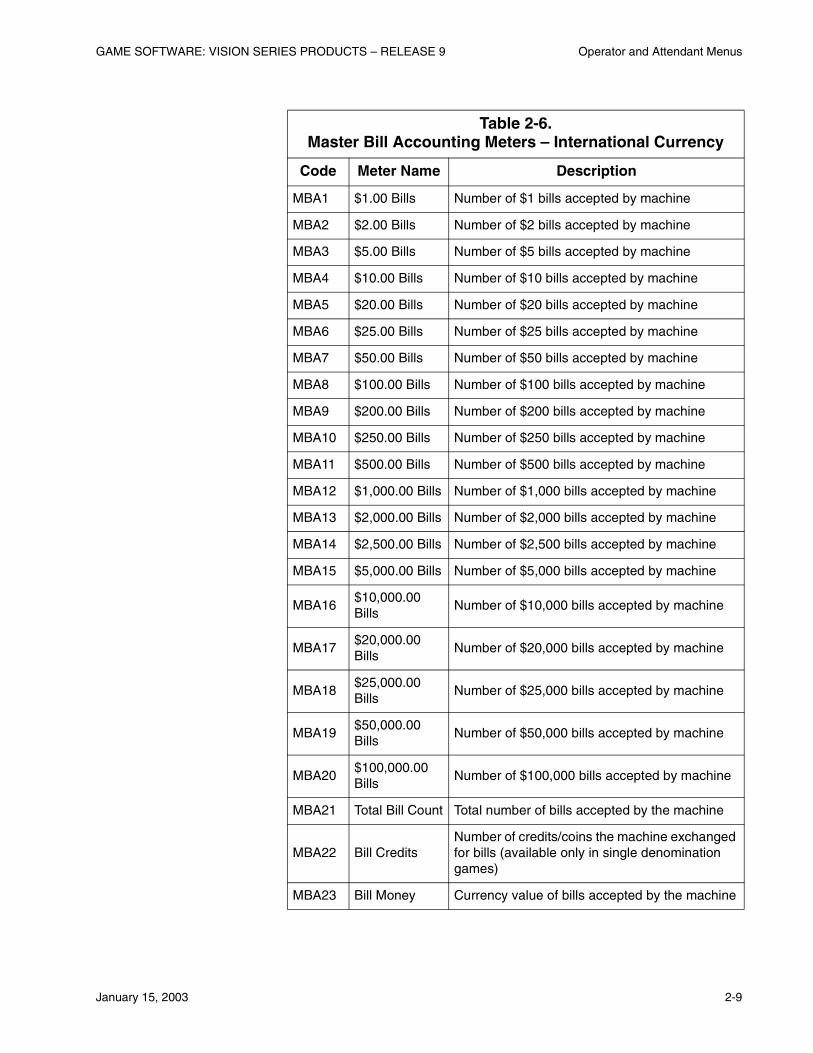
Master Bill Accounting (Option: [1.1.1.3])
Select the Master Bill Accounting option to view meters required to keep track of bills accepted by the bill validator. Table 2-5 provides a listing of the master bill accounting meters for U.S. currency. Refer to Table 2-6 for a list of the master bill accounting meters for international currency.
Table 2-5. Master Bill Accounting Meters – U.S. Currency
Code Meter Name Description
MBA1 $1.00 Bills Number of $1 bills accepted by machine
MBA2 $2.00 Bills Number of $2 bills accepted by machine
MBA3 $5.00 Bills Number of $5 bills accepted by machine
MBA4 $10.00 Bills Number of $10 bills accepted by machine
MBA5 $20.00 Bills Number of $20 bills accepted by machine
MBA6 $50.00 Bills Number of $50 bills accepted by machine
MBA7 $100.00 Bills Number of $100 bills accepted by machine
MBA8 Total Bill Count Number of bills accepted by machine
MBA9 Bill CreditsNumber of credits/coins the machine exchanged for bills (available only in single denomination games)
MBA10 Bill Money Dollar value of bills accepted by machine
GAME SOFTWARE: VISION SERIES PRODUCTS – RELEASE 9 Operator and Attendant Menus
January 15, 2003 2-9
Table 2-6. Master Bill Accounting Meters – International Currency
Code Meter Name Description
MBA1 $1.00 Bills Number of $1 bills accepted by machine
MBA2 $2.00 Bills Number of $2 bills accepted by machine
MBA3 $5.00 Bills Number of $5 bills accepted by machine
MBA4 $10.00 Bills Number of $10 bills accepted by machine
MBA5 $20.00 Bills Number of $20 bills accepted by machine
MBA6 $25.00 Bills Number of $25 bills accepted by machine
MBA7 $50.00 Bills Number of $50 bills accepted by machine
MBA8 $100.00 Bills Number of $100 bills accepted by machine
MBA9 $200.00 Bills Number of $200 bills accepted by machine
MBA10 $250.00 Bills Number of $250 bills accepted by machine
MBA11 $500.00 Bills Number of $500 bills accepted by machine
MBA12 $1,000.00 Bills Number of $1,000 bills accepted by machine
MBA13 $2,000.00 Bills Number of $2,000 bills accepted by machine
MBA14 $2,500.00 Bills Number of $2,500 bills accepted by machine
MBA15 $5,000.00 Bills Number of $5,000 bills accepted by machine
MBA16$10,000.00 Bills
Number of $10,000 bills accepted by machine
MBA17$20,000.00 Bills
Number of $20,000 bills accepted by machine
MBA18$25,000.00 Bills
Number of $25,000 bills accepted by machine
MBA19$50,000.00 Bills
Number of $50,000 bills accepted by machine
MBA20$100,000.00 Bills
Number of $100,000 bills accepted by machine
MBA21 Total Bill Count Total number of bills accepted by the machine
MBA22 Bill CreditsNumber of credits/coins the machine exchanged for bills (available only in single denomination games)
MBA23 Bill Money Currency value of bills accepted by the machine
Operator and Attendant Menus GAME SOFTWARE: VISION SERIES PRODUCTS – RELEASE 9
2-10 January 15, 2003
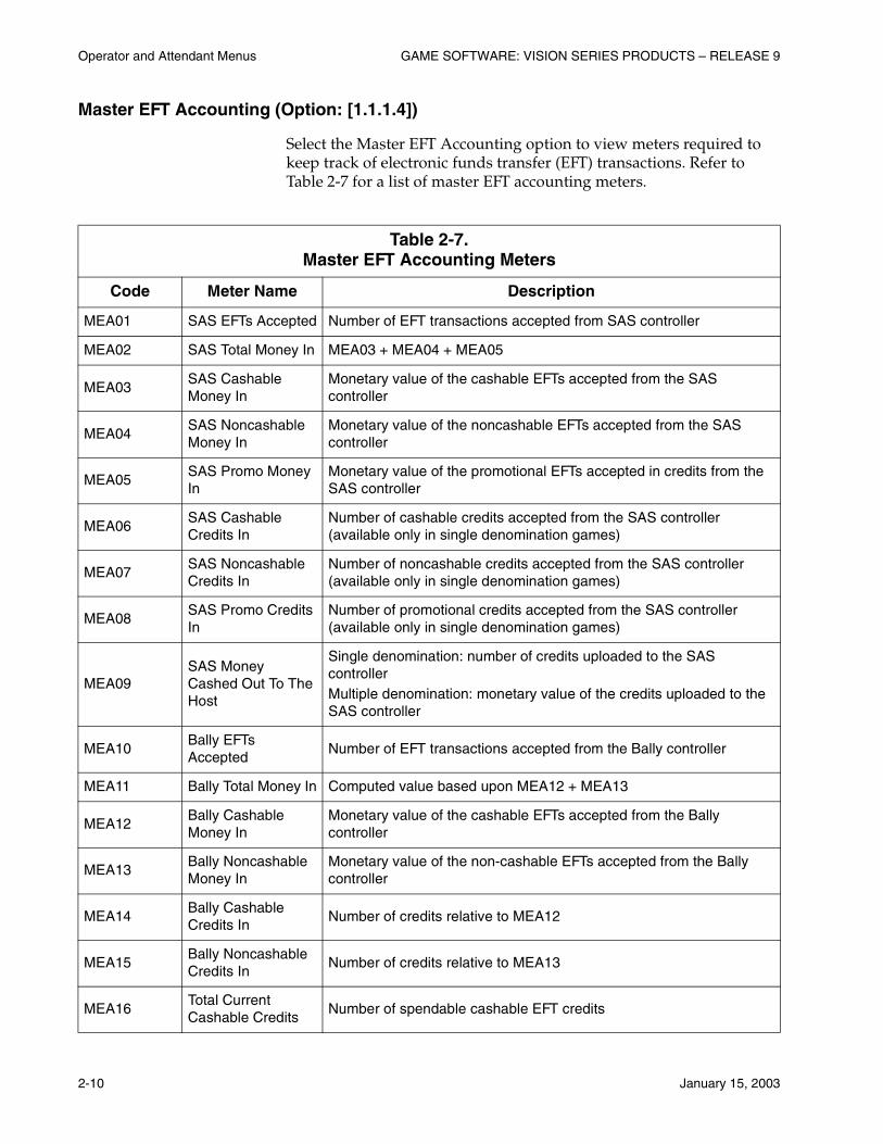
Master EFT Accounting (Option: [1.1.1.4])
Select the Master EFT Accounting option to view meters required to keep track of electronic funds transfer (EFT) transactions. Refer to Table 2-7 for a list of master EFT accounting meters.
Table 2-7. Master EFT Accounting Meters
Code Meter Name Description
MEA01 SAS EFTs Accepted Number of EFT transactions accepted from SAS controller
MEA02 SAS Total Money In MEA03 + MEA04 + MEA05
MEA03SAS Cashable Money In
Monetary value of the cashable EFTs accepted from the SAS controller
MEA04SAS Noncashable Money In
Monetary value of the noncashable EFTs accepted from the SAS controller
MEA05SAS Promo Money In
Monetary value of the promotional EFTs accepted in credits from the SAS controller
MEA06SAS Cashable Credits In
Number of cashable credits accepted from the SAS controller (available only in single denomination games)
MEA07SAS Noncashable Credits In
Number of noncashable credits accepted from the SAS controller (available only in single denomination games)
MEA08SAS Promo Credits In
Number of promotional credits accepted from the SAS controller (available only in single denomination games)
MEA09SAS Money Cashed Out To The Host
Single denomination: number of credits uploaded to the SAS controllerMultiple denomination: monetary value of the credits uploaded to the SAS controller
MEA10Bally EFTs Accepted
Number of EFT transactions accepted from the Bally controller
MEA11 Bally Total Money In Computed value based upon MEA12 + MEA13
MEA12Bally Cashable Money In
Monetary value of the cashable EFTs accepted from the Bally controller
MEA13Bally Noncashable Money In
Monetary value of the non-cashable EFTs accepted from the Bally controller
MEA14Bally Cashable Credits In
Number of credits relative to MEA12
MEA15Bally Noncashable Credits In
Number of credits relative to MEA13
MEA16Total Current Cashable Credits
Number of spendable cashable EFT credits
GAME SOFTWARE: VISION SERIES PRODUCTS – RELEASE 9 Operator and Attendant Menus
January 15, 2003 2-11
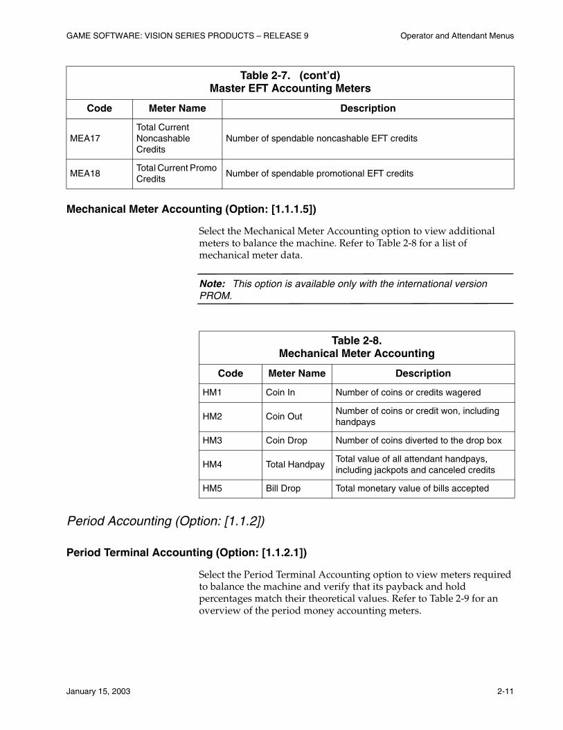
Mechanical Meter Accounting (Option: [1.1.1.5])
Select the Mechanical Meter Accounting option to view additional meters to balance the machine. Refer to Table 2-8 for a list of mechanical meter data.
Note: This option is available only with the international version PROM.
Period Accounting (Option: [1.1.2])
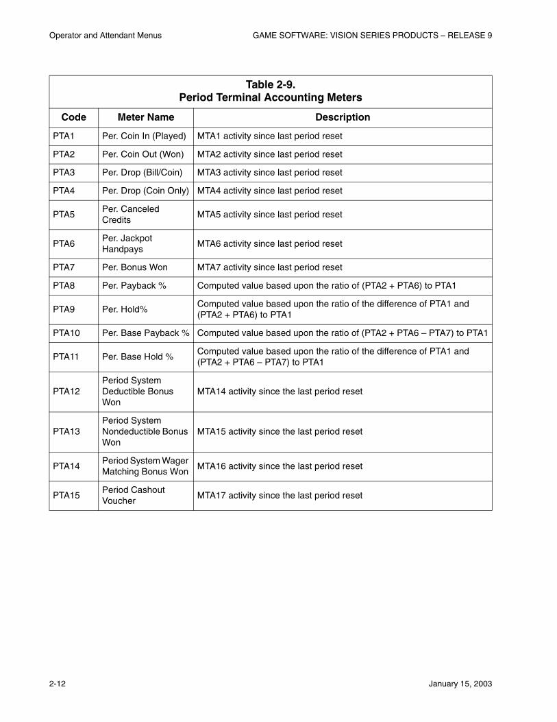
Period Terminal Accounting (Option: [1.1.2.1])
Select the Period Terminal Accounting option to view meters required to balance the machine and verify that its payback and hold percentages match their theoretical values. Refer to Table 2-9 for an overview of the period money accounting meters.
MEA17Total Current Noncashable Credits
Number of spendable noncashable EFT credits
MEA18Total Current Promo Credits
Number of spendable promotional EFT credits
Table 2-8. Mechanical Meter Accounting
Code Meter Name Description
HM1 Coin In Number of coins or credits wagered
HM2 Coin OutNumber of coins or credit won, including handpays
HM3 Coin Drop Number of coins diverted to the drop box
HM4 Total HandpayTotal value of all attendant handpays, including jackpots and canceled credits
HM5 Bill Drop Total monetary value of bills accepted
Table 2-7. (cont’d)Master EFT Accounting Meters
Code Meter Name Description
Operator and Attendant Menus GAME SOFTWARE: VISION SERIES PRODUCTS – RELEASE 9
2-12 January 15, 2003
Table 2-9. Period Terminal Accounting Meters
Code Meter Name Description
PTA1 Per. Coin In (Played) MTA1 activity since last period reset
PTA2 Per. Coin Out (Won) MTA2 activity since last period reset
PTA3 Per. Drop (Bill/Coin) MTA3 activity since last period reset
PTA4 Per. Drop (Coin Only) MTA4 activity since last period reset
PTA5Per. Canceled Credits
MTA5 activity since last period reset
PTA6Per. Jackpot Handpays
MTA6 activity since last period reset
PTA7 Per. Bonus Won MTA7 activity since last period reset
PTA8 Per. Payback % Computed value based upon the ratio of (PTA2 + PTA6) to PTA1
PTA9 Per. Hold%Computed value based upon the ratio of the difference of PTA1 and (PTA2 + PTA6) to PTA1
PTA10 Per. Base Payback % Computed value based upon the ratio of (PTA2 + PTA6 – PTA7) to PTA1
PTA11 Per. Base Hold %Computed value based upon the ratio of the difference of PTA1 and (PTA2 + PTA6 – PTA7) to PTA1
PTA12Period System Deductible Bonus Won
MTA14 activity since the last period reset
PTA13Period System Nondeductible Bonus Won
MTA15 activity since the last period reset
PTA14Period System Wager Matching Bonus Won
MTA16 activity since the last period reset
PTA15Period Cashout Voucher
MTA17 activity since the last period reset
GAME SOFTWARE: VISION SERIES PRODUCTS – RELEASE 9 Operator and Attendant Menus
January 15, 2003 2-13
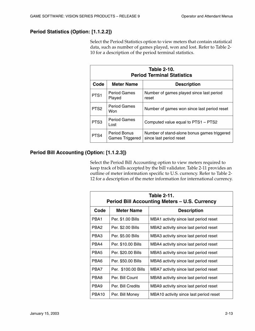
Period Statistics (Option: [1.1.2.2])
Select the Period Statistics option to view meters that contain statistical data, such as number of games played, won and lost. Refer to Table 2-10 for a description of the period terminal statistics.
Period Bill Accounting (Option: [1.1.2.3])
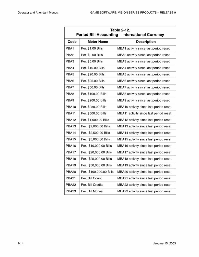
Select the Period Bill Accounting option to view meters required to keep track of bills accepted by the bill validator. Table 2-11 provides an outline of meter information specific to U.S. currency. Refer to Table 2-12 for a description of the meter information for international currency.
Table 2-10. Period Terminal Statistics
Code Meter Name Description
PTS1Period Games Played
Number of games played since last period reset
PTS2Period Games Won
Number of games won since last period reset
PTS3Period Games Lost
Computed value equal to PTS1 – PTS2
PTS4Period Bonus Games Triggered
Number of stand-alone bonus games triggered since last period reset
Table 2-11. Period Bill Accounting Meters – U.S. Currency
Code Meter Name Description
PBA1 Per. $1.00 Bills MBA1 activity since last period reset
PBA2 Per. $2.00 Bills MBA2 activity since last period reset
PBA3 Per. $5.00 Bills MBA3 activity since last period reset
PBA4 Per. $10.00 Bills MBA4 activity since last period reset
PBA5 Per. $20.00 Bills MBA5 activity since last period reset
PBA6 Per. $50.00 Bills MBA6 activity since last period reset
PBA7 Per. $100.00 Bills MBA7 activity since last period reset
PBA8 Per. Bill Count MBA8 activity since last period reset
PBA9 Per. Bill Credits MBA9 activity since last period reset
PBA10 Per. Bill Money MBA10 activity since last period reset
Operator and Attendant Menus GAME SOFTWARE: VISION SERIES PRODUCTS – RELEASE 9
2-14 January 15, 2003
Table 2-12. Period Bill Accounting – International Currency
Code Meter Name Description
PBA1 Per. $1.00 Bills MBA1 activity since last period reset
PBA2 Per. $2.00 Bills MBA2 activity since last period reset
PBA3 Per. $5.00 Bills MBA3 activity since last period reset
PBA4 Per. $10.00 Bills MBA4 activity since last period reset
PBA5 Per. $20.00 Bills MBA5 activity since last period reset
PBA6 Per. $25.00 Bills MBA6 activity since last period reset
PBA7 Per. $50.00 Bills MBA7 activity since last period reset
PBA8 Per. $100.00 Bills MBA8 activity since last period reset
PBA9 Per. $200.00 Bills MBA9 activity since last period reset
PBA10 Per. $250.00 Bills MBA10 activity since last period reset
PBA11 Per. $500.00 Bills MBA11 activity since last period reset
PBA12 Per. $1,000.00 Bills MBA12 activity since last period reset
PBA13 Per. $2,000.00 Bills MBA13 activity since last period reset
PBA14 Per. $2,500.00 Bills MBA14 activity since last period reset
PBA15 Per. $5,000.00 Bills MBA15 activity since last period reset
PBA16 Per. $10,000.00 Bills MBA16 activity since last period reset
PBA17 Per. $20,000.00 Bills MBA17 activity since last period reset
PBA18 Per. $25,000.00 Bills MBA18 activity since last period reset
PBA19 Per. $50,000.00 Bills MBA19 activity since last period reset
PBA20 Per. $100,000.00 Bills MBA20 activity since last period reset
PBA21 Per. Bill Count MBA21 activity since last period reset
PBA22 Per. Bill Credits MBA22 activity since last period reset
PBA23 Per. Bill Money MBA23 activity since last period reset
GAME SOFTWARE: VISION SERIES PRODUCTS – RELEASE 9 Operator and Attendant Menus
January 15, 2003 2-15
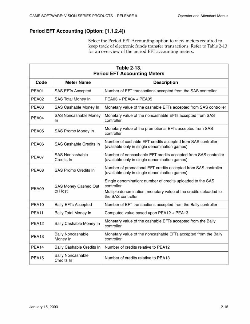
Period EFT Accounting (Option: [1.1.2.4])
Select the Period EFT Accounting option to view meters required to keep track of electronic funds transfer transactions. Refer to Table 2-13 for an overview of the period EFT accounting meters.
Table 2-13. Period EFT Accounting Meters
Code Meter Name Description
PEA01 SAS EFTs Accepted Number of EFT transactions accepted from the SAS controller
PEA02 SAS Total Money In PEA03 + PEA04 + PEA05
PEA03 SAS Cashable Money In Monetary value of the cashable EFTs accepted from SAS controller
PEA04SAS Noncashable Money In
Monetary value of the noncashable EFTs accepted from SAS controller
PEA05 SAS Promo Money InMonetary value of the promotional EFTs accepted from SAS controller
PEA06 SAS Cashable Credits InNumber of cashable EFT credits accepted from SAS controller (available only in single denomination games)
PEA07SAS Noncashable Credits In
Number of noncashable EFT credits accepted from SAS controller (available only in single denomination games)
PEA08 SAS Promo Credits InNumber of promotional EFT credits accepted from SAS controller (available only in single denomination games)
PEA09SAS Money Cashed Out to Host
Single denomination: number of credits uploaded to the SAS controllerMultiple denomination: monetary value of the credits uploaded to the SAS controller
PEA10 Bally EFTs Accepted Number of EFT transactions accepted from the Bally controller
PEA11 Bally Total Money In Computed value based upon PEA12 + PEA13
PEA12 Bally Cashable Money InMonetary value of the cashable EFTs accepted from the Bally controller
PEA13Bally Noncashable Money In
Monetary value of the noncashable EFTs accepted from the Bally controller
PEA14 Bally Cashable Credits In Number of credits relative to PEA12
PEA15Bally Noncashable Credits In
Number of credits relative to PEA13
Operator and Attendant Menus GAME SOFTWARE: VISION SERIES PRODUCTS – RELEASE 9
2-16 January 15, 2003
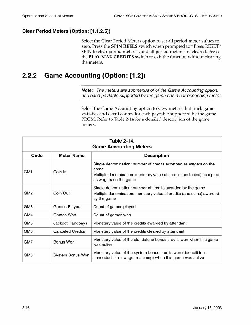
Clear Period Meters (Option: [1.1.2.5])
Select the Clear Period Meters option to set all period meter values to zero. Press the SPIN REELS switch when prompted to “Press RESET/SPIN to clear period meters”, and all period meters are cleared. Press the PLAY MAX CREDITS switch to exit the function without clearing the meters.
2.2.2 Game Accounting (Option: [1.2])
Note: The meters are submenus of of the Game Accounting option, and each paytable supported by the game has a corresponding meter.
Select the Game Accounting option to view meters that track game statistics and event counts for each paytable supported by the game PROM. Refer to Table 2-14 for a detailed description of the game meters.
Table 2-14. Game Accounting Meters
Code Meter Name Description
GM1 Coin In
Single denomination: number of credits accetped as wagers on the gameMultiple denomination: monetary value of credits (and coins) accepted as wagers on the game
GM2 Coin OutSingle denomination: number of credits awarded by the gameMultiple denomination: monetary value of credits (and coins) awarded by the game
GM3 Games Played Count of games played
GM4 Games Won Count of games won
GM5 Jackpot Handpays Monetary value of the credits awarded by attendant
GM6 Canceled Credits Monetary value of the credits cleared by attendant
GM7 Bonus WonMonetary value of the standalone bonus credits won when this game was active
GM8 System Bonus WonMonetary value of the system bonus credits won (deductible + nondeductible + wager matching) when this game was active
GAME SOFTWARE: VISION SERIES PRODUCTS – RELEASE 9 Operator and Attendant Menus
January 15, 2003 2-17
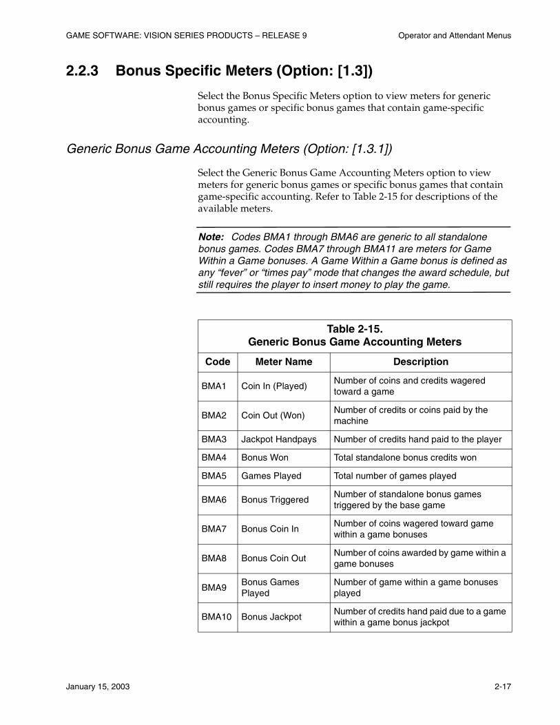
2.2.3 Bonus Specific Meters (Option: [1.3])
Select the Bonus Specific Meters option to view meters for generic bonus games or specific bonus games that contain game-specific accounting.
Generic Bonus Game Accounting Meters (Option: [1.3.1])
Select the Generic Bonus Game Accounting Meters option to view meters for generic bonus games or specific bonus games that contain game-specific accounting. Refer to Table 2-15 for descriptions of the available meters.
Note: Codes BMA1 through BMA6 are generic to all standalone bonus games. Codes BMA7 through BMA11 are meters for Game Within a Game bonuses. A Game Within a Game bonus is defined as any “fever” or “times pay” mode that changes the award schedule, but still requires the player to insert money to play the game.
Table 2-15. Generic Bonus Game Accounting Meters
Code Meter Name Description
BMA1 Coin In (Played)Number of coins and credits wagered toward a game
BMA2 Coin Out (Won)Number of credits or coins paid by the machine
BMA3 Jackpot Handpays Number of credits hand paid to the player
BMA4 Bonus Won Total standalone bonus credits won
BMA5 Games Played Total number of games played
BMA6 Bonus TriggeredNumber of standalone bonus games triggered by the base game
BMA7 Bonus Coin InNumber of coins wagered toward game within a game bonuses
BMA8 Bonus Coin OutNumber of coins awarded by game within a game bonuses
BMA9Bonus Games Played
Number of game within a game bonuses played
BMA10 Bonus JackpotNumber of credits hand paid due to a game within a game bonus jackpot
Operator and Attendant Menus GAME SOFTWARE: VISION SERIES PRODUCTS – RELEASE 9
2-18 January 15, 2003
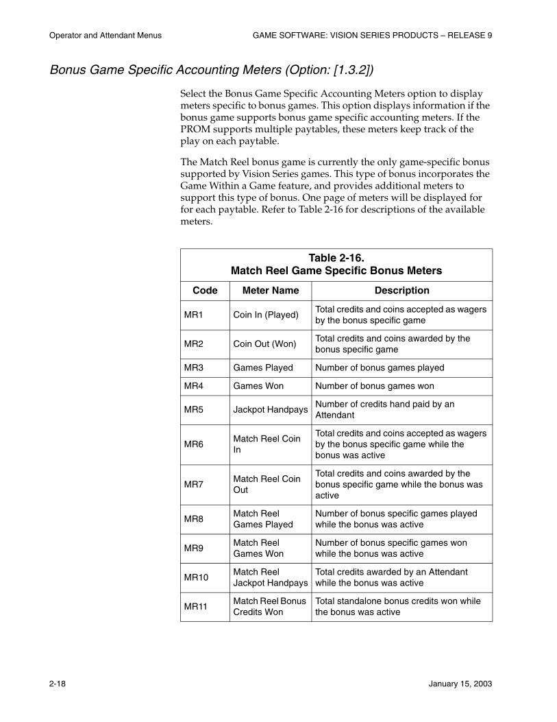
Bonus Game Specific Accounting Meters (Option: [1.3.2])
Select the Bonus Game Specific Accounting Meters option to display meters specific to bonus games. This option displays information if the bonus game supports bonus game specific accounting meters. If the PROM supports multiple paytables, these meters keep track of the play on each paytable.
The Match Reel bonus game is currently the only game-specific bonus supported by Vision Series games. This type of bonus incorporates the Game Within a Game feature, and provides additional meters to support this type of bonus. One page of meters will be displayed for for each paytable. Refer to Table 2-16 for descriptions of the available meters.
Table 2-16. Match Reel Game Specific Bonus Meters
Code Meter Name Description
MR1 Coin In (Played)Total credits and coins accepted as wagers by the bonus specific game
MR2 Coin Out (Won)Total credits and coins awarded by the bonus specific game
MR3 Games Played Number of bonus games played
MR4 Games Won Number of bonus games won
MR5 Jackpot HandpaysNumber of credits hand paid by an Attendant
MR6Match Reel Coin In
Total credits and coins accepted as wagers by the bonus specific game while the bonus was active
MR7Match Reel Coin Out
Total credits and coins awarded by the bonus specific game while the bonus was active
MR8Match Reel Games Played
Number of bonus specific games played while the bonus was active
MR9Match Reel Games Won
Number of bonus specific games won while the bonus was active
MR10Match Reel Jackpot Handpays
Total credits awarded by an Attendant while the bonus was active
MR11Match Reel Bonus Credits Won
Total standalone bonus credits won while the bonus was active
GAME SOFTWARE: VISION SERIES PRODUCTS – RELEASE 9 Operator and Attendant Menus
January 15, 2003 2-19
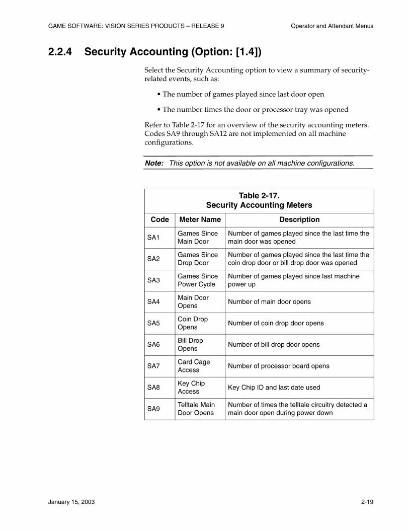
2.2.4 Security Accounting (Option: [1.4])
Select the Security Accounting option to view a summary of security-related events, such as:
• The number of games played since last door open
• The number times the door or processor tray was opened
Refer to Table 2-17 for an overview of the security accounting meters. Codes SA9 through SA12 are not implemented on all machine configurations.
Note: This option is not available on all machine configurations.
Table 2-17. Security Accounting Meters
Code Meter Name Description
SA1Games Since Main Door
Number of games played since the last time the main door was opened
SA2Games Since Drop Door
Number of games played since the last time the coin drop door or bill drop door was opened
SA3Games Since Power Cycle
Number of games played since last machine power up
SA4Main Door Opens
Number of main door opens
SA5Coin Drop Opens
Number of coin drop door opens
SA6Bill Drop Opens
Number of bill drop door opens
SA7Card Cage Access
Number of processor board opens
SA8Key Chip Access
Key Chip ID and last date used
SA9Telltale Main Door Opens
Number of times the telltale circuitry detected a main door open during power down
Operator and Attendant Menus GAME SOFTWARE: VISION SERIES PRODUCTS – RELEASE 9
2-20 January 15, 2003
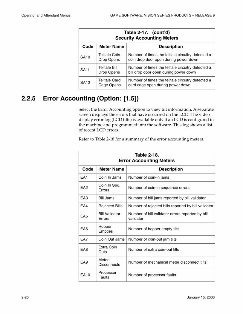
2.2.5 Error Accounting (Option: [1.5])
Select the Error Accounting option to view tilt information. A separate screen displays the errors that have occurred on the LCD. The video display error log (LCD tilts) is available only if an LCD is configured in the machine and programmed into the software. This log shows a list of recent LCD errors.
Refer to Table 2-18 for a summary of the error accounting meters.
SA10Telltale Coin Drop Opens
Number of times the telltale circuitry detected a coin drop door open during power down
SA11Telltale Bill Drop Opens
Number of times the telltale circuitry detected a bill drop door open during power down
SA12Telltale Card Cage Opens
Number of times the telltale circuitry detected a card cage open during power down
Table 2-18. Error Accounting Meters
Code Meter Name Description
EA1 Coin In Jams Number of coin-in jams
EA2Coin In Seq. Errors
Number of coin-in sequence errors
EA3 Bill Jams Number of bill jams reported by bill validator
EA4 Rejected Bills Number of rejected bills reported by bill validator
EA5Bill Validator Errors
Number of bill validator errors reported by bill validator
EA6Hopper Empties
Number of hopper empty tilts
EA7 Coin Out Jams Number of coin-out jam tilts
EA8Extra Coin Outs
Number of extra coin-out tilts
EA9Meter Disconnects
Number of mechanical meter disconnect tilts
EA10Processor Faults
Number of processor faults
Table 2-17. (cont’d)Security Accounting Meters
Code Meter Name Description
GAME SOFTWARE: VISION SERIES PRODUCTS – RELEASE 9 Operator and Attendant Menus
January 15, 2003 2-21
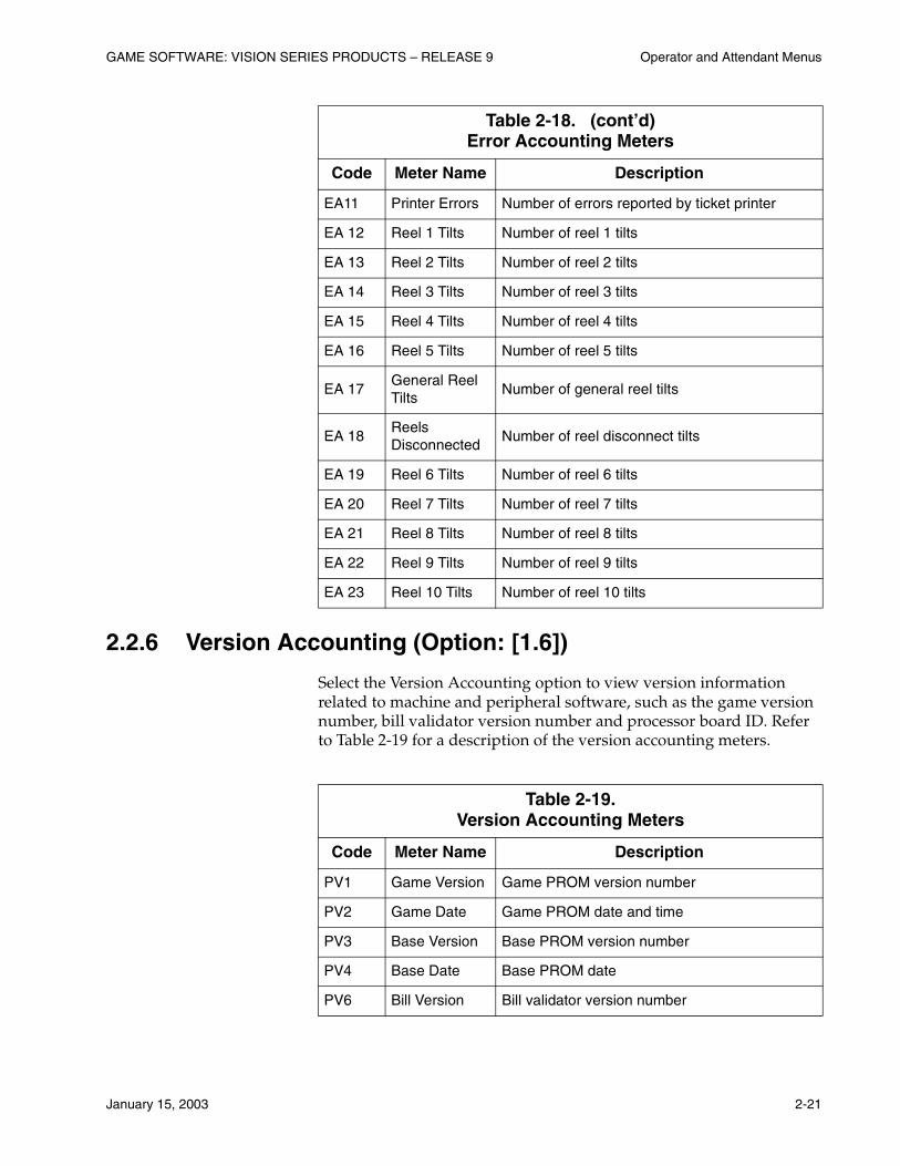
2.2.6 Version Accounting (Option: [1.6])
Select the Version Accounting option to view version information related to machine and peripheral software, such as the game version number, bill validator version number and processor board ID. Refer to Table 2-19 for a description of the version accounting meters.
EA11 Printer Errors Number of errors reported by ticket printer
EA 12 Reel 1 Tilts Number of reel 1 tilts
EA 13 Reel 2 Tilts Number of reel 2 tilts
EA 14 Reel 3 Tilts Number of reel 3 tilts
EA 15 Reel 4 Tilts Number of reel 4 tilts
EA 16 Reel 5 Tilts Number of reel 5 tilts
EA 17General Reel Tilts
Number of general reel tilts
EA 18Reels Disconnected
Number of reel disconnect tilts
EA 19 Reel 6 Tilts Number of reel 6 tilts
EA 20 Reel 7 Tilts Number of reel 7 tilts
EA 21 Reel 8 Tilts Number of reel 8 tilts
EA 22 Reel 9 Tilts Number of reel 9 tilts
EA 23 Reel 10 Tilts Number of reel 10 tilts
Table 2-19. Version Accounting Meters
Code Meter Name Description
PV1 Game Version Game PROM version number
PV2 Game Date Game PROM date and time
PV3 Base Version Base PROM version number
PV4 Base Date Base PROM date
PV6 Bill Version Bill validator version number
Table 2-18. (cont’d)Error Accounting Meters
Code Meter Name Description

Operator and Attendant Menus GAME SOFTWARE: VISION SERIES PRODUCTS – RELEASE 9
2-22 January 15, 2003
2.2.7 Master Progressive Accounting (Option: [1.7])
Select the Master Progressive Accounting option to view accounting information on non-WAP progressive jackpot hits by level. Refer to Table 2-20 for information about the progressive accounting meters.
Note: This option is displayed only on non-WAP machines. In addition, the General Progressive Accounting [1.7.1] and WAP Accounting [1.7.2] options are not displayed on non-WAP machines.
PV7Primary DotM Version
VFD version number
PV8 Printer Version Printer version number (standard printer)
PV9Printer2 Version
Ticket printer version number (thermal printer)
PV10Theoretical Payback %
The expected payback percentage of the game
PV11 Proc Board ID Processor board ID
PV13Spectrum Version
Spectrum version number
PV14 Version Name Version PROM number
PV15 Version Date Version PROM date and time
PV16 Sound Version Sound version number or “Not Configured”
PV17Auxiliary Bonus Device Version
If an auxiliary device is present, the program version number for the device software
PV18Auxiliary Dot Matrix Version
If an auxiliary VFD is present , the VFD version number
Table 2-20. Master Progressive Accounting Meters
Code Meter Name Description
PA1 Level 1 Hits Number of progressive level 1 jackpot hits
PA2 Level 2 Hits Number of progressive level 2 jackpot hits
PA3 Level 3 Hits Number of progressive level 3 jackpot hits
Table 2-19. (cont’d)Version Accounting Meters
Code Meter Name Description

GAME SOFTWARE: VISION SERIES PRODUCTS – RELEASE 9 Operator and Attendant Menus
January 15, 2003 2-23
General Progressive Accounting (Option: [1.7.1])
Select the General Progressive Accounting option to view accounting information on WAP progressive jackpot hits by level. Refer to Table 2-21 for information about the progressive accounting meters.
Note: This option is available only on WAP machines. In addition, the Master Progressive Accounting Meters shown in Table 2-20 are not displayed on WAP machines.
PA4 Level 4 Hits Number of progressive level 4 jackpot hits
PA5 Level 5 Hits Number of progressive level 5 jackpot hits
PA6 Level 6 Hits Number of progressive level 6 jackpot hits
PA7 Level 7 Hits Number of progressive level 7 jackpot hits
PA8 Level 8 Hits Number of progressive level 8 jackpot hits
PA9Total Progressive Hits
Sum of PA1 through PA8
Table 2-21. General Progressive Accounting Meters
Code Meter Name Description
PA1 Level 1 Hits Number of progressive level 1 jackpot hits
PA2 Level 2 Hits Number of progressive level 2 jackpot hits
PA3 Level 3 Hits Number of progressive level 3 jackpot hits
PA4 Level 4 Hits Number of progressive level 4 jackpot hits
PA5 Level 5 Hits Number of progressive level 5 jackpot hits
PA6 Level 6 Hits Number of progressive level 6 jackpot hits
PA7 Level 7 Hits Number of progressive level 7 jackpot hits
PA8 Level 8 Hits Number of progressive level 8 jackpot hits
PA9Total Progressive Hits
Sum of PA1 through PA8
Table 2-20. (cont’d)Master Progressive Accounting Meters
Code Meter Name Description

Operator and Attendant Menus GAME SOFTWARE: VISION SERIES PRODUCTS – RELEASE 9
2-24 January 15, 2003
WAP Accounting (Option: [1.7.2])
Select the WAP Accounting option to view accounting information on WAP meters. Refer to Table 2-22 for an overview of the WAP accounting meters.
Note: This option is available only on WAP machines. In addition, the Master Progressive Accounting Meters shown in Table 2-20 are not displayed on WAP machines.
Meters WA1 through WA5 and WA9 through WA11 are displayed only for WAP Type 2 games. Meters WA12 through WA23 are displayed only for WAP Type 7 games.
Table 2-22. WAP Accounting Meters
Code Meter Name Description
WA1 Coin In TotalMonetary value of the coins wagered towards a game
WA2Coin Out Total
Monetary value of the coins won excluding system awards
WA3Handpay Total
Monetary value of the coins hand paid excluding system awards
WA4Coin In Total Since Last JP
Monetary value of the coins wagered towards since the last jackpot
WA5Coin Drop Total
Number of coins diverted to the drop box
WA6Progressives Won
Number of progressive hits
WA7 Games Won Number of games won
WA8 Games lost Number of games lost
WA9 Coin In Tilts Number of coin in tilts
WA10 Door Opens Number of main door opens
WA11 Resets Number of power resets
WA12Total Money In
Total amount of money inserted into the machine
WA13Total Money Out
Total amount of money cashed out to the hopper or printer
WA14Money In (Bills)
Total amount of money credited by the bill validator
GAME SOFTWARE: VISION SERIES PRODUCTS – RELEASE 9 Operator and Attendant Menus
January 15, 2003 2-25
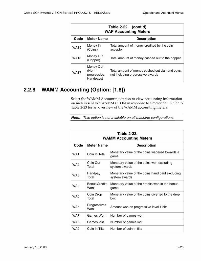
2.2.8 WAMM Accounting (Option: [1.8])
Select the WAMM Accounting option to view accounting information on meters sent to a WAMM CCOM in response to a meter poll. Refer to Table 2-23 for an overview of the WAMM accounting meters.
Note: This option is not available on all machine configurations.
WA15Money In (Coins)
Total amount of money credited by the coin acceptor
WA16Money Out (Hopper)
Total amount of money cashed out to the hopper
WA17
Money Out (Non-progressive Handpays)
Total amount of money cashed out via hand pays, not including progressive awards
Table 2-23. WAMM Accounting Meters
Code Meter Name Description
WA1 Coin In TotalMonetary value of the coins wagered towards a game
WA2Coin Out Total
Monetary value of the coins won excluding system awards
WA3Handpay Total
Monetary value of the coins hand paid excluding system awards
WA4Bonus Credits Won
Monetary value of the credits won in the bonus game
WA5Coin Drop Total
Monetary value of the coins diverted to the drop box
WA6Progressives Won
Amount won on progressive level 1 hits
WA7 Games Won Number of games won
WA8 Games lost Number of games lost
WA9 Coin In Tilts Number of coin-in tilts
Table 2-22. (cont’d)WAP Accounting Meters
Code Meter Name Description

Operator and Attendant Menus GAME SOFTWARE: VISION SERIES PRODUCTS – RELEASE 9
2-26 January 15, 2003
2.2.9 PSAMS Accounting (Option: [1.9])
Select the PSAMS Accounting option to view accounting information for machines that use the Progressive Security and Accounting Management System (PSAMS).
Note: This option is not available on all machine configurations.
PSAMS Terminal Accounting (Option: [1.9.1])
The PSAMS Terminal Accounting option displays PSAMS meter information for the machine. Refer to Table 2-24 for a detailed list of available accounting information.
WA10Main Door Opens
Number of main door opens
WA11 Resets Number of power resets
WA12Machine Address
WAMM machine address
Table 2-24. PSAMS Terminal Accounting Meters
Code Meter Name Description
PS1 Money In Bills and coins accepted by the machine
PS2 Money Out Money paid out by the machine in cents
PS3 Credits Amount of credits on the machine’s credit meter
PS4 DropNumber of bills accepted and coins diverted to the drop box
PS5 Handpay Money hand paid excluding progressive wins
PS6 Bills In Monetary amount of bills accepted
PS7 Reserved 1 Reserved meter 1
PS8 Reserved 2 Reserved meter 2
Table 2-23. (cont’d)WAMM Accounting Meters
Code Meter Name Description
GAME SOFTWARE: VISION SERIES PRODUCTS – RELEASE 9 Operator and Attendant Menus
January 15, 2003 2-27
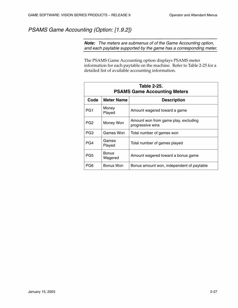
PSAMS Game Accounting (Option: [1.9.2])
Note: The meters are submenus of of the Game Accounting option, and each paytable supported by the game has a corresponding meter.
The PSAMS Game Accounting option displays PSAMS meter information for each paytable on the machine. Refer to Table 2-25 for a detailed list of available accounting information.
Table 2-25. PSAMS Game Accounting Meters
Code Meter Name Description
PG1Money Played
Amount wagered toward a game
PG2 Money WonAmount won from game play, excluding progressive wins
PG3 Games Won Total number of games won
PG4Games Played
Total number of games played
PG5Bonus Wagered
Amount wagered toward a bonus game
PG6 Bonus Won Bonus amount won, independent of paytable
Operator and Attendant Menus GAME SOFTWARE: VISION SERIES PRODUCTS – RELEASE 9
2-28 January 15, 2003
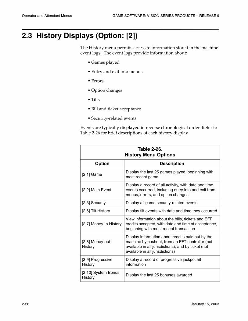
2.3 History Displays (Option: [2])
The History menu permits access to information stored in the machine event logs. The event logs provide information about:
• Games played
• Entry and exit into menus
• Errors
• Option changes
• Tilts
• Bill and ticket acceptance
• Security-related events
Events are typically displayed in reverse chronological order. Refer to Table 2-26 for brief descriptions of each history display.
Table 2-26. History Menu Options
Option Description
[2.1] GameDisplay the last 25 games played, beginning with most recent game
[2.2] Main EventDisplay a record of all activity, with date and time events occurred, including entry into and exit from menus, errors, and option changes
[2.3] Security Display all game security-related events
[2.6] Tilt History Display tilt events with date and time they occurred
[2.7] Money-In HistoryView information about the bills, tickets and EFT credits accepted, with date and time of acceptance, beginning with most recent transaction
[2.8] Money-out History
Display information about credits paid out by the machine by cashout, from an EFT controller (not available in all jurisdictions), and by ticket (not available in all jurisdictions)
[2.9] Progressive History
Display a record of progressive jackpot hit information
[2.10] System Bonus History
Display the last 25 bonuses awarded
GAME SOFTWARE: VISION SERIES PRODUCTS – RELEASE 9 Operator and Attendant Menus
January 15, 2003 2-29
2.3.1 Game History Displays (Option: [2.1])
Game History (Option: [2.1.1])
Select the Game History option to display information about the 10 most recent games played and up to the last 50 bonus steps. The most recently completed game is shown first, followed by previous games in reverse chronological order. The information can be used to verify game outcome to resolve player disputes.
Use the following steps to view game history information:
1. Turn the Attendant key when prompted. The reels spin to the stops reached in the most recent game and the meters display the credits won, total credits and coins played.
2. Press the CHANGE and CASH/CREDIT switches to navigate forward and backward through the games.
3. Press the SPIN REELS switch to cycle through the events for a game. The following events occur:
• Reels spin to the stops
• LCD displays the related bonus activity
• VFD shows information such as date and time the game was played, the reel stop numbers, and the credits won, total credits and coins played.
4. Press the SPIN REELS switch again to view the up to the last 50 bonus steps.
5. Press the PLAY MAX CREDITS switch to exit.
Game State History {Option: [2.1.2])
Note: This option is available only from the Operator menu.
The Game State History screen displays a record of recent machine states. Use this option when working with IGT Engineering to troubleshoot a machine problem.
The individual states are coded and identified by number. The most recent state is shown first, followed by previous states in reverse order. These states are not time-date stamped.
Press the SPIN REELS switch to page down through the list of events. The button is not lit if the list of records is shorter than a page.
Operator and Attendant Menus GAME SOFTWARE: VISION SERIES PRODUCTS – RELEASE 9
2-30 January 15, 2003
2.3.2 Main Event History (Option: [2.2])
Select the Main Event History option to display a listing of machine activity. This screen provides a record of all processing events, and can be used to diagnose possible problems.
The most recent history for the machine is shown first, followed by previous events in reverse chronological order. The display includes events such as:
• Entry into and exit from a menu
• Option changes
• Power cycles
• Errors
• Clear events
• Tilts
• Game starts
• Meter credits
• Door opens
The date and time are shown for each event. Press the SPIN REELS switch to page down through the list of events. The button is not lit if the list is shorter than a page.
2.3.3 Security History (Option: [2.3])
Generic Security History (Option: [2.3.1])
The Generic Security History option displays all game security-related events, such as machine power up, door access, and key chip menu access.
The screen displays the events in reverse chronological order, and the date and time of each event. Press the SPIN REELS switch to page down through the list. The button is not lit if the list is shorter than a page.

GAME SOFTWARE: VISION SERIES PRODUCTS – RELEASE 9 Operator and Attendant Menus
January 15, 2003 2-31
Bonus Setup History (Option: [2.3.2])
The Bonus Setup History option displays the bonus settings that were on the machine before the configuration was last changed.
Note: This option cannot be accessed if generic bonus games are not supported by the machine.
The screen displays the events in reverse chronological order, and the date and time of each event. Press the CHANGE and CASH/CREDIT switches to navigate forward and backward through the list. Press the SPIN REELS switch to browse the next group of settings. The switch is not lit if the list is shorter than a page.
Bonus Meters History (Option: [2.3.3])
Note: This option cannot be accessed if generic bonus games are not supported by the machine.
The Bonus Meters History option displays the snapshot meters for standalone bonus games. The machine saves the last 10 bonus meter snaphots. Press the SPIN REELS switch to change the snapshot being viewed. Press the CHANGE and CASH/CREDIT switches to navigate forward and backward through a list of meters. Press the BET MAX CREDITS switch to exit the screen. Refer to Table 2-27 for a description of the meter data displayed.
Table 2-27. Bonus Meters History Display
Code Meter Name Description
# Snapshot Back
Current location in the list of 10 available meter snapshots
KeychipDate and time the key chip procedure was last performed
Bonus Theme Bonus graphics theme supported by the LCD
Payback Percentage
Bonus game payback percentage
BMA1Coin In (Played)
Number of coins and credits wagered toward a game
BMA2Coin Out (Won)
Number of coins and credits paid by the machine due to a win, including partial pay amounts

Operator and Attendant Menus GAME SOFTWARE: VISION SERIES PRODUCTS – RELEASE 9
2-32 January 15, 2003
2.3.4 Tilt History (Option: [2.4])
The Tilt History screen displays a list of all game tilt conditions. The most recent tilt is shown first, followed by previous tilts in reverse chronological order.
This display includes events such as:
• VFD failures
• Individual reel tilts
• Meter disconnects
• Hopper empties
• Printer errors
• Stacker opens
• Reel mechanism disconnects
BMA3Drop (Coin Only)
Number of coins diverted to the drop
BMA4Jackpot Handpays
Number of credits hand paid to the player
BMA5 Bonus Won Total standalone bonus credits won
BMA6 Games Played Number of games played
BMA7Bonus Triggered
Number of times the machine triggered the standalone bonus game
BMA8 Bonus Coin InNumber of coins wagered toward a Game Within a Game
BMA9Bonus Coin Out
Number of coins won during a Game Within a Game
BMA10Bns Games Played
Number of games played during a Game Within a Game session
BMA11 Bonus JackpotNumber of handpay credits in a Game Within a Game session
Table 2-27. (cont’d)Bonus Meters History Display
Code Meter Name Description

GAME SOFTWARE: VISION SERIES PRODUCTS – RELEASE 9 Operator and Attendant Menus
January 15, 2003 2-33
The display includes the date and time of each event. Use the SPIN REELS switch to navigate through the display. The button is not lit if the list is shorter than a page. Press the PLAY MAX CREDITS switch to exit the option.
2.3.5 Money-In History (Option: [2.5])
Bill-In History (Option: [2.5.1])
The Bill-In History screen displays a listing of the last 25 bills accepted. The most recent bill accept is shown first, followed by previous accepts in reverse chronological order. The display includes the bill denomination, and the date and time of each accept.
Use the SPIN REELS switch to navigate through the display. The button is not lit if the list is shorter than a page. Press the PLAY MAX CREDITS switch to exit the option.
Voucher-In History (Option: [2.5.2])
Note: This screen does not appear if the machine is not configured to accept tickets.
The Voucher-In History screen displays a listing of the last 50 tickets accepted. The most recent ticket accept is shown first, followed by previous accepts in reverse chronological order. The display includes the ticket amount, date and time of each accept.
Use the SPIN REELS switch to navigate through the display. The button is not lit if the list is shorter than a page. Press the PLAY MAX CREDITS switch to exit the option.
EFT History (Option: [2.5.3])
The EFT History screen displays a log of accepted credits. The display includes the date and time of acceptance, the type (cashable, non-cashable or promotional) and the controller (SAS).
Use the SPIN REELS switch to navigate through the display. The button is not lit if the list is shorter than a page. Press the PLAY MAX CREDITS switch to exit the option.
Operator and Attendant Menus GAME SOFTWARE: VISION SERIES PRODUCTS – RELEASE 9
2-34 January 15, 2003
2.3.6 Money-Out History (Option: [2.6])
The Money-Out History screen displays a log of credits paid by the machine, including credits paid to an EFT controller, by ticket or by cash. The display includes the following information:
• Date and time of the cash out, and the amount
• For EFT transactions, the type (cashable, noncashable or promotional) and the controller (SAS)
Use the SPIN REELS switch to navigate through the display. The button is not lit if the list is shorter than a page. Press the PLAY MAX CREDITS switch to exit the option.
Ticket History (Option: [2.6.1])
The Ticket Transactions screen displays a log of credits paid out via ticket by the machine. The display includes the following information:
• Date and time of the cash out, and the amount
• For EFT transactions, the type (cashable, noncashable or promotional) and the controller (SAS)
Use the SPIN REELS switch to navigate through the display. The button is not lit if the list is shorter than a page. Press the PLAY MAX CREDITS switch to exit the option.
Other Transactions (Option: [2.6.2])
The Other cashout history screen displays records of cashout or win payments from the hopper or printer, and wins requiring a hand pay. The display includes the following information:
• Date and time of the cash out, and the amount
• For EFT transactions, the type (cashable, noncashable or promotional) and the controller (SAS)
Use the SPIN REELS switch to navigate through the display. The button is not lit if the list is shorter than a page. Press the PLAY MAX CREDITS switch to exit the option.
GAME SOFTWARE: VISION SERIES PRODUCTS – RELEASE 9 Operator and Attendant Menus
January 15, 2003 2-35
2.3.7 Progressive History (Option: [2.7])
The Progressive History screen displays a record of progressive jackpot hits.
Note: This option is available only on non-WAP machines.
Terminal (Option: [2.7.1])
The Terminal History screen displays jackpot hit information, such as the jackpot date, time, amount, and level for all progressive controllers.
Use the SPIN REELS switch to navigate through the display. The button is not lit if the list is shorter than a page. Press the PLAY MAX CREDITS switch to exit the option.
2.3.8 System Bonus History (Option: [2.8])
The System Bonus History screen displays the last 25 bonuses awarded by the SAS host. Each record contains the total amount of credits awarded, the tax status, and the bonus type.
Use the SPIN REELS switch to navigate through the display. The button is not lit if the list is shorter than a page. Press the PLAY MAX CREDITS switch to exit the option.
Operator and Attendant Menus GAME SOFTWARE: VISION SERIES PRODUCTS – RELEASE 9
2-36 January 15, 2003
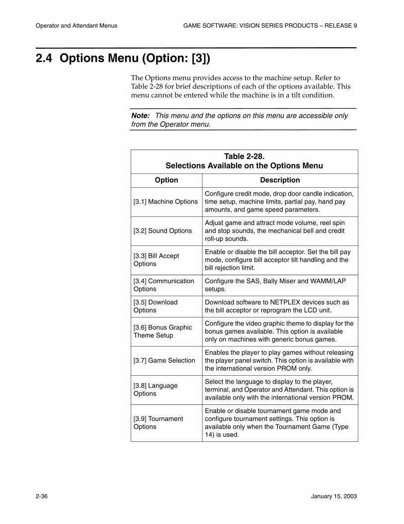
2.4 Options Menu (Option: [3])
The Options menu provides access to the machine setup. Refer to Table 2-28 for brief descriptions of each of the options available. This menu cannot be entered while the machine is in a tilt condition.
Note: This menu and the options on this menu are accessible only from the Operator menu.
Table 2-28. Selections Available on the Options Menu
Option Description
[3.1] Machine OptionsConfigure credit mode, drop door candle indication, time setup, machine limits, partial pay, hand pay amounts, and game speed parameters.
[3.2] Sound OptionsAdjust game and attract mode volume, reel spin and stop sounds, the mechanical bell and credit roll-up sounds.
[3.3] Bill Accept Options
Enable or disable the bill acceptor. Set the bill pay mode, configure bill acceptor tilt handling and the bill rejection limit.
[3.4] Communication Options
Configure the SAS, Bally Miser and WAMM/LAP setups.
[3.5] Download Options
Download software to NETPLEX devices such as the bill acceptor or reprogram the LCD unit.
[3.6] Bonus Graphic Theme Setup
Configure the video graphic theme to display for the bonus games available. This option is available only on machines with generic bonus games.
[3.7] Game SelectionEnables the player to play games without releasing the player panel switch. This option is available with the international version PROM only.
[3.8] Language Options
Select the language to display to the player, terminal, and Operator and Attendant. This option is available only with the international version PROM.
[3.9] Tournament Options
Enable or disable tournament game mode and configure tournament settings. This option is available only when the Tournament Game (Type 14) is used.
GAME SOFTWARE: VISION SERIES PRODUCTS – RELEASE 9 Operator and Attendant Menus
January 15, 2003 2-37
2.4.1 Machine Options (Option: [3.1])
Credit Option (Option: [3.1.1])
Use the Credit Option screen to select from one of the following four credit modes:
• Credit – all credits are paid to the credit meter until the player presses the cash out button.
Note: The credit option is the only option available when the ticket printer is enabled.
• Noncredit – all credits are paid from the hopper unless the win is greater than the hopper limit. Otherwise, the machine will require a hand pay. The machine does not allow EFT and will act like a bill changer while in this mode, regardless of bill validator pay mode settings.
• Player Initiated Credit – initiated when the player presses the CASH/CREDIT switch while the machine is idle with zero credits on the credit meter.
The player-initiated credit option defaults to the noncredit mode when the credit meter remains at zero for more than 30 seconds, or when any accumulated credits are cashed out.
• Player Initiated Noncredit – initiated when the player presses the CASH/CREDIT switch while the machine is idle, has zero credits on the credit meter and is in credit mode.
The player-initiated noncredit option defaults to the credit mode if the game is idle for 30 seconds, and remains in the credit mode when credits are cashed out.
To set the credit mode, use the following steps:
1. Navigate through the list of settings using the CHANGE and CASH/CREDIT switches.
2. Press the PLAY MAX CREDITS switch to exit the screen and save the changes, or press the SPIN REELS switch to reset the value to the previous setting.
Operator and Attendant Menus GAME SOFTWARE: VISION SERIES PRODUCTS – RELEASE 9
2-38 January 15, 2003
Candles (Option: [3.1.2])
Reactive Candle Timer (Option: [3.1.2.1])
Use the Reactive Candle Timer screen to set the candle flash rate. If enabled, the candle flash rate progressively increases for the following conditions:
• Handpays
• Any tilts not related to the machine’s doors
• System errors
The candle will increase its flash rate to the next flash rate after the time period expires. Set the value to a number between 1 and 99 minutes. To disable the timer, set the value to 0. Use the following steps to set the timer:
1. The screen displays the current setting. Press the CHANGE switch to navigate between the digits.
2. Press the CASH/CREDIT switch to increment the current digit.
3. Press the SPIN REELS switch to reset the value to the previous setting, or press the PLAY MAX CREDITS switch to save the new setting and exit the screen.
Door Closure Candle On/Off(Option: [3.1.2.2])
Use the Door Candle screen to enable or disable the door candle. If enabled, a candle lamp flashes for one complete game to indicate main/bill door closure. If disabled, the candle does not flash after the main/bill door is closed.
Use the following steps to enable or disable the door candle:
1. Navigate through the list of settings using the CHANGE and CASH/CREDIT switches.
2. Press the PLAY MAX CREDITS switch to exit the screen and save the changes, or press the SPIN REELS switch to reset the value to the previous setting.
Drop-Door Candle (Option: [3.2.2.3])
Use the Drop-Door Candle screen to enable or disable the drop door candle. If enabled, the bottom level on the candle flashes at twice the normal door-open rate when the drop door is opened. If disabled, the candle is not affected when the drop door is opened. Use the following steps to enable or disable the drop-door candle:
GAME SOFTWARE: VISION SERIES PRODUCTS – RELEASE 9 Operator and Attendant Menus
January 15, 2003 2-39
1. Navigate through the list of settings using the CHANGE and CASH/CREDIT switches.
2. Press the PLAY MAX CREDITS switch to exit the screen and save the changes, or press the SPIN REELS switch to reset the value to the previous setting.
Set Time (Option: [3.1.3])
Use the Set Time screen to adjust the time and date on the real-time clock (RTC). Use the following procedure to set the real-time clock:
1. The screen displays the current setting. Press the CHANGE switch to navigate between the digits.
2. Press the CASH/CREDIT switch to increment the current digit.
3. Press the SPIN REELS switch to reset the value to the previous setting, or press the PLAY MAX CREDITS switch to save the new setting and exit the screen.
Limits (Option: [3.1.4])
Select the Limits screen to adjust the hopper, credit, jackpot and bill acceptor credit limits:
• Hopper Limit – determines the maximum number of coins the machine will pay from the hopper.
• Credit Limit – sets the maximum number of credits that the machine will allow on its credit meter. If the player attempts to insert more coins, the machine will divert them to the coin tray.
• Jackpot Limit – determines the maximum number of credits that can be won from one game before the machine triggers a hand pay condition. This limit must be greater than or equal to the hopper limit.
• Bill Credit Limit – defines the maximum number of credits that can be put on the credit meter by inserting a bill. The limit must be less than the credit limit and $2,500.
Use the following procedure to set the machine limits:
1. The current limits are displayed on the screen. Press the CASH/CREDIT switch to navigate between fields.
Operator and Attendant Menus GAME SOFTWARE: VISION SERIES PRODUCTS – RELEASE 9
2-40 January 15, 2003
2. Press the SPIN REELS switch to change the limit amount. Use the following switches to change the value:
a. CHANGE – to navigate among the digits
b. CASH/CREDIT – to increment a digit
3. Press the SPIN REELS switch to reset the value, or press the PLAY MAX CREDITS switch to save the changes and exit the field.
4. Press the PLAY MAX CREDITS switch to save the changes and exit the screen.
Partial Pay (Option: [3.1.5])
Note: This menu and the associated options are available only on non-WAP machines, when the printer is disabled.
Partial Pay Amount (Option: 3.1.5.1])
Select the Partial Pay Amount option to set the amount paid from the hopper when a single win exceeds the hopper limit. The partial pay amount is paid from the hopper before the machine locks up for a hand pay.
Note: The partial pay amount cannot be set to a value greater than the hopper limit.
Use the following steps to configure the partial pay amount:
1. The screen displays the current setting. Press the CHANGE switch to navigate between the digits.
2. Press the CASH/CREDIT switch to increment the current digit.
3. Press the SPIN REELS switch to reset the value to the previous setting, or press the PLAY MAX CREDITS switch to save the new setting and exit the screen.
Odd Pay (Option: [3.1.5.2])
Select the Odd Pay option to enable or disable payment of fractional dollar amounts from the hopper. If enabled, the hopper will pay the fractional amount before the machine locks up for a hand pay, allowing the hand pay to be an even dollar amount.
Note: This option is available only when the game is in tokenization mode.
GAME SOFTWARE: VISION SERIES PRODUCTS – RELEASE 9 Operator and Attendant Menus
January 15, 2003 2-41
Use the following steps to enable or disable odd pays:
1. Navigate through the list of settings using the CHANGE and CASH/CREDIT switches.
2. Press the PLAY MAX CREDITS switch to exit the screen and save the changes, or press the SPIN REELS switch to reset the value to the previous setting.
Handpay Display (Option: [3.1.6])
Select the Handpay Display screen to enable or disable display of the hand pay amount on the VFD/LCD. If enabled, the machine displays a hand pay message and the amount to be paid. If disabled, only the hand pay message is displayed.
Use the following steps to enable or disable the handpay display:
1. Navigate through the list of settings using the CHANGE and CASH/CREDIT switches.
2. Press the PLAY MAX CREDITS switch to exit the screen and save the changes, or press the SPIN REELS switch to reset the value to the previous setting.
Player Cashout Menu (Option: [3.1.7])
If the machine’s ticket printer is enabled, the player may divide the cashout amount between the hopper and a ticket. When the player presses the CASH/CREDIT switch, the game uses the limits configured using the Player Coin Limit option, and the number of credits on the meter to determine the eligible cashout devices. The game then prompts the player with the available options.
Note: To use this option, the machine must be equipped with a thermal ticket printer and the appropriate software, and the ticket printer must be enabled.
Enable/Disable (Option: 3.1.7.1])
Use the following steps to enable or disable the player cashout option:
1. Navigate through the list of settings using the CHANGE and CASH/CREDIT switches.
2. Press the PLAY MAX CREDITS switch to exit the screen and save the changes, or press the SPIN REELS switch to reset the value to the previous setting.
Operator and Attendant Menus GAME SOFTWARE: VISION SERIES PRODUCTS – RELEASE 9
2-42 January 15, 2003
Player Coin Limit (Option: 3.1.7.2])
This option configures the maximum amount that can be paid from the hopper when payouts are split between the hopper and the printer using the Player Cashout option.
Note: The player coin limit cannot be greater than the hopper limit.
Use the following steps to configure the player coin limit:
1. The screen displays the current setting. Press the CHANGE switch to navigate between the digits.
2. Press the CASH/CREDIT switch to increment the current digit.
3. Press the SPIN REELS switch to reset the value to the previous setting, or press the PLAY MAX CREDITS switch to save the new setting and exit the screen.
Quick Coin (Option: 3.1.7.3])
The Quick Coin feature enables the player to generate a partial cashout from the hopper. Use the Quick Coin option to determine the amount of partial cash the player can request. If the amount on the credit meter is less than the quick coin amount, the player cannot request a partial cashout.
Use the following steps to configure the quick coin amount:
1. The screen displays the current setting. Press the CHANGE switch to navigate between the digits.
2. Press the CASH/CREDIT switch to increment the current digit.
3. Press the SPIN REELS switch to reset the value to the previous setting, or press the PLAY MAX CREDITS switch to save the new setting and exit the screen.
W2-G Setup (Option: [3.1.8])
Note: The machine hardware must include the proper harnessing and an extra reset switch for the W2-G feature to function properly.
Select the W2-G Setup menu to configure W2-G settings. The purpose of this feature is to minimize the number of jackpot hand pays. Jackpots can be reset to the credit meter under the following conditions:
• The win must be equal to or greater than the lower jackpot limit
GAME SOFTWARE: VISION SERIES PRODUCTS – RELEASE 9 Operator and Attendant Menus
January 15, 2003 2-43
• The win must be less than the upper jackpot limit
• Current credits plus the win must be equal to or less than the credit limit
W2-G Controller (Option: [3.1.8.1])
Set the controller to one of the following:
• Controlled by SAS – the jackpot cannot be reset until authorization is sent to the machine by the SAS system. The operator must turn the W2-G reset key to place the win on the credit meter.
• Controlled by the operator – the operator may turn the Attendant key to hand pay the win, or the W2-G reset key to reset the win to the credit meter.
Note: If SAS authorization is required, SAS must communicate on the primary channel. Refer to Section 2.4.4 for procedures to set the communication channel.
Use the following procedure to set the W2-G controller:
1. Turn the W2-G reset key when prompted. The screen displays the current setting.
2. Navigate through the list of settings using the CHANGE and CASH/CREDIT switches.
3. Press the PLAY MAX CREDITS switch to exit the screen and save the changes, or press the SPIN REELS switch to reset the value to the previous setting.
W2-G Limit (Option: [3.1.8.2])
Use the following procedure to configure the W2-G limit:
1. Turn the second reset key when prompted. The screen displays the current setting.
2. Press the CHANGE switch to navigate between the digits.
3. Press the CASH/CREDIT switch to increment the current digit.
4. Press the SPIN REELS switch to reset the limit to the previous value, or press the PLAY MAX CREDITS switch to save the new setting and exit the screen.
Operator and Attendant Menus GAME SOFTWARE: VISION SERIES PRODUCTS – RELEASE 9
2-44 January 15, 2003
Machine Serial Number (Option: [3.1.9])
Note: The serial number entered on this screen must match the number on the machine’s model tag.
Configure a machine serial number up to nine digits for transmission to the WAP/WAMM system. Use the Machine Serial Number screen to set the serial number as follows:
1. The screen displays the current setting. Press the CHANGE switch to navigate between the digits.
2. Press the CASH/CREDIT switch to increment the current digit.
3. Press the SPIN REELS switch to reset the value to the previous setting, or press the PLAY MAX CREDITS switch to save the new setting and exit the screen.
Printer (Option: [3.1.10])
Select the Printer menu to configure the ticket printer.
Note: Printer configuration screens cannot be accessed if the machine does not have an enabled ticket printer.
Data Entry (Option: [3.1.10.1])
Use the following steps on the Data Entry screen to enter the establishment name and address that will be printed on all cash out tickets:
1. The screen displays the current ticket data. Press the SPIN REELS switch to navigate through the fields.
2. Press the BET ONE CREDIT switch to move through the characters in a field.
3. Press the CHANGE and CASH/CREDIT switches to change the current character. The SELECT list at the top of the screen displays the available characters and numbers.
4. Press the PLAY MAX CREDITS switch to exit the screen and save the changes.
GAME SOFTWARE: VISION SERIES PRODUCTS – RELEASE 9 Operator and Attendant Menus
January 15, 2003 2-45
Print Button (Option: [3.1.10.2])
Enables or disables the PRINT button display on the screen.
Note: This option is available only if the machine is configured with an impact or dot matrix printer.
Use the following steps to enable or disable this feature:
1. Navigate through the list of settings using the CHANGE and CASH/CREDIT switches.
2. Press the PLAY MAX CREDITS switch to exit the screen and save the changes, or press the SPIN REELS switch to reset the value to the previous setting.
Remainder (Option: 3.1.20.3])
Determines the minimum amount that remains on the credit meter when the machine automatically cashes out due to an exceeded credit limit.
Use the following steps to set the remainder:
1. The screen displays the current setting. Press the CHANGE switch to navigate between the digits.
2. Press the CASH/CREDIT switch to increment the current digit.
3. Press the SPIN REELS switch to reset the value to the previous setting, or press the PLAY MAX CREDITS switch to save the new setting and exit the screen.
Printer Tilts (Option: [3.1.10.4])
The Printer Tilt Setup screen sets the level of machine tilt that will occur when the printer has an error:
• Soft Tilt – the top level of the candle flashes, and the reason for the tilt is displayed on the VFD when either the main door or bill door is opened
• Hard Tilt – game play halts until the tilt is cleared
Note: IGT recommends configuring the machine to create a hard tilt when the printer has an error.

Operator and Attendant Menus GAME SOFTWARE: VISION SERIES PRODUCTS – RELEASE 9
2-46 January 15, 2003
Use the following steps to set the printer tilt:
1. Navigate through the list of settings using the CHANGE and CASH/CREDIT switches.
2. Press the PLAY MAX CREDITS switch to exit the screen and save the changes, or press the SPIN REELS switch to reset the value to the previous setting.
Split Pay (Option: [3.1.11])
Select the Split Pay menu to configure split pay parameters.
Note: The machine must be equipped with a thermal printer with the appropriate software, the ticket printer must be enabled and the hopper limit must be greater than zero to use this option.
If the payout is not divisible by the hopper denomination, the coin pay limit is ignored and the entire amount is paid by ticket.
Enable/Disable (Option: [3.1.11.1])
If the Split Pay option is enabled, a payout equal to or less than the coin pay limit is made from the hopper and the amount above the coin pay limit, if any, is paid by ticket. A jackpot condition locks up the machine, and the screen displays CALL ATTENDANT – JACKPOT.
If the Split Pay option is disabled, the entire payout amount is paid from the hopper if the amount is equal to or less than the coin pay limit. If the amount is above the coin pay limit, the entire amount is paid by ticket.
Enable or disable split pay as follows:
1. Navigate through the list of settings using the CHANGE and CASH/CREDIT switches.
2. Press the PLAY MAX CREDITS switch to exit the screen and save the changes, or press the SPIN REELS switch to reset the value to the previous setting.
GAME SOFTWARE: VISION SERIES PRODUCTS – RELEASE 9 Operator and Attendant Menus
January 15, 2003 2-47
Limits (Option: [3.1.11.2])
If the payout amount is above the coin pay limit, the entire payout amount is paid by ticket. A jackpot condition locks up the machine, and the screen displays CALL ATTENDANT – JACKPOT.
Note: The coin pay limit cannot be set to a value greater than the hopper limit.
Set the coin pay limit as follows:
1. The screen displays the current setting. Press the CHANGE switch to navigate between the digits.
2. Press the CASH/CREDIT switch to increment the current digit.
3. Press the SPIN REELS switch to reset the value to the previous setting, or press the PLAY MAX CREDITS switch to save the new setting and exit the screen.
2.4.2 Sound Options (Option: [3.2])
Volume Control/Game Volume (Option: [3.2.1])
Note: If the machine has an LCD/M-Slave installed, some sounds are played by that device. Use the Setups and Info options provided by the LCD/M-Slave to control those sounds. The options on this menu affect only the sounds generated by the base machine.
Game Volume (Option: [3.2.1.1])
Use the Game Volume option to set the volume for game play music and sound effects. Set the volume using the following procedure:
1. Navigate through the list of settings using the CHANGE and CASH/CREDIT switches.
2. Press the PLAY MAX CREDITS switch to exit the screen and save the changes, or press the SPIN REELS switch to reset the value to the previous setting.
Money Volume (Option: [3.2.1.2])
Use the Money Volume option to set the volume for monetary transactions, such as bill in and out and ticket in and out.

Operator and Attendant Menus GAME SOFTWARE: VISION SERIES PRODUCTS – RELEASE 9
2-48 January 15, 2003
Set the volume using the following procedure:
1. Navigate through the list of settings using the CHANGE and CASH/CREDIT switches.
2. Press the PLAY MAX CREDITS switch to exit the screen and save the changes, or press the SPIN REELS switch to reset the value to the previous setting.
Reel Spin Sound (Option: [3.2.2])
Note: This option is not available on all machine configurations.
Select the Reel Spin Sound screen to enable or disable spin sounds. If the spin sound is enabled, a random note melody plays while the reels are spinning. If disabled, no sound is made while the reels spin. Enable or disable spin sounds using the following procedure:
1. Navigate through the list of settings using the CHANGE and CASH/CREDIT switches.
2. Press the PLAY MAX CREDITS switch to exit the screen and save the changes, or press the SPIN REELS switch to reset the value to the previous setting.
Reel Stop Sound (Option: [3.2.3])
Note: This option is not available on all machine configurations.
Select the Reel Stop Sound screen to determine the sound played when the reels come to a stop. The following sounds are available:
• None
• Speaker (produced by the sound processor)
• Solenoid (handle-solenoid clicks)
Set the stop sound using the following procedure:
1. Navigate through the list of settings using the CHANGE and CASH/CREDIT switches.
2. Press the PLAY MAX CREDITS switch to exit the screen and save the changes, or press the SPIN REELS switch to reset the value to the previous setting.

GAME SOFTWARE: VISION SERIES PRODUCTS – RELEASE 9 Operator and Attendant Menus
January 15, 2003 2-49
Mechanical Bell (Option: [3.2.4])
Select the Mechanical Bell screen to indicate when the bell should ring. The following options are available:
• Off
• Ring for all wins
• Ring for hand pays only
Configure the bell using the following procedure:
1. Navigate through the list of settings using the CHANGE and CASH/CREDIT switches.
2. Press the PLAY MAX CREDITS switch to exit the screen and save the changes, or press the SPIN REELS switch to reset the value to the previous setting.
Rollup Tones (Option: [3.2.5])
Note: This option is not available on all machine configurations.
Use the Roll Up Tones screen to set the sound played while credits are awarded to the player:
• Rollup tones – normal (single tone)
• Rollup melody – enhanced melody
Configure rollup tones using the following procedure:
1. Navigate through the list of settings using the CHANGE and CASH/CREDIT switches.
2. Press the PLAY MAX CREDITS switch to exit the screen and save the changes, or press the SPIN REELS switch to reset the value to the previous setting.
Multimedia (Option: [3.2.6])
This menu allows the operator to configure the machine for specific multimedia options if a Multimedia Lite board is installed.
Audio Mode (Option: [3.2.6.1])
Set the playback sound to mono or stereo depending on the wiring harnesses and hardware options in the machine.
Operator and Attendant Menus GAME SOFTWARE: VISION SERIES PRODUCTS – RELEASE 9
2-50 January 15, 2003
Configure the audio mode using the following procedure:
1. Navigate through the list of settings using the CHANGE and CASH/CREDIT switches.
2. Press the PLAY MAX CREDITS switch to exit the screen and save the changes, or press the SPIN REELS switch to reset the value to the previous setting.
Attract Time (Option: [3.2.6.2])
When the machine enters idle mode with no credits on the meter, the machine plays a random attract sound once. Use the Attract Time option to configure the amount of time that elapses before the machine plays the random attract sound.
Set the attract time using the following steps:
1. The screen displays the current setting. Press the CHANGE switch to navigate between the digits.
2. Press the CASH/CREDIT switch to increment the current digit.
3. Press the SPIN REELS switch to reset the value to the previous setting, or press the PLAY MAX CREDITS switch to save the new setting and exit the screen.
Attract Volume (Option: [3.2.6.3])
Use the Attract Volume option to configure the volume level at which the attract sound is played.
1. Navigate through the list of settings using the CHANGE and CASH/CREDIT switches.
2. Press the PLAY MAX CREDITS switch to exit the screen and save the changes, or press the SPIN REELS switch to reset the value to the previous setting.
Reel Spin Option (Option: [3.2.6.4])
Note: This option is not available on all machine configurations.
Use the Reel Spin Option screen to configure the sound made while the reels spin:
• Generic – universal stereo melody
• Enhanced – one or more enhanced stereo melodies
GAME SOFTWARE: VISION SERIES PRODUCTS – RELEASE 9 Operator and Attendant Menus
January 15, 2003 2-51
• S-Plus™ Legacy – random S-Plus notes
Note: To play the S-Plus Legacy reel spin sounds, the appropriate sound chip must be installed on the Multimedia Lite board.
1. Navigate through the list of settings using the CHANGE and CASH/CREDIT switches.
2. Press the PLAY MAX CREDITS switch to exit the screen and save the changes, or press the SPIN REELS switch to reset the value to the previous setting.
Handpay Option (Option: [3.2.6.5])
Note: This option is not available on all machine configurations.
Use the Handpay Option screen to configure the sound made while the machine is waiting for a hand pay:
• Game Theme – stereo sounds that are part of the game theme
• S-Plus Legacy – random S-Plus notes
1. Navigate through the list of settings using the CHANGE and CASH/CREDIT switches.
2. Press the PLAY MAX CREDITS switch to exit the screen and save the changes, or press the SPIN REELS switch to reset the value to the previous setting.
Rollup Option (Option: [3.2.6.6])
Note: This option is not available on all machine configurations.
Use the Rollup Option screen to configure the sound made while credits rollup on the meter, and during coin in, bill in and cash out:
• Game Theme – stereo sounds that are part of the game theme
• S-Plus Legacy – random S-Plus notes
1. Navigate through the list of settings using the CHANGE and CASH/CREDIT switches.
2. Press the PLAY MAX CREDITS switch to exit the screen and save the changes, or press the SPIN REELS switch to reset the value to the previous setting.

Operator and Attendant Menus GAME SOFTWARE: VISION SERIES PRODUCTS – RELEASE 9
2-52 January 15, 2003
Haywire Option (Option: [3.2.6.7])
Note: This option is not available on all machine configurations.
Use the Haywire Option screen to configure the sound made when the machine is in Haywire!® mode:
• Game Theme – stereo sounds that are part of the game theme
• S-Plus Legacy – random S-Plus notes
1. Navigate through the list of settings using the CHANGE and CASH/CREDIT switches.
2. Press the PLAY MAX CREDITS switch to exit the screen and save the changes, or press the SPIN REELS switch to reset the value to the previous setting.
2.4.3 Bill Acceptor (Option: [3.3])
Enable/Disable (Option: [3.3.1])
Select the bill acceptor Enable/Disable screen to configure whether or not the bill validator accepts bills. Use the following steps to enable or disable the bill acceptor:
1. Navigate through the list of settings using the CHANGE and CASH/CREDIT switches.
2. Press the PLAY MAX CREDITS switch to exit the screen and save the changes, or press the SPIN REELS switch to reset the value to the previous setting.
Bill Pay Mode (Option: [3.3.2])
Select the Bill Pay Mode screen to configure how bills are paid when accepted by the machine:
• To Credit Always – causes the credit meter to increment
• According to Credit Mode – uses the credit type configured on the Credit Mode screen
• To Hopper Always – exchanges bills for coins paid from the hopper, even if the player has selected the credit mode
1. Navigate through the list of settings using the CHANGE and CASH/CREDIT switches.
GAME SOFTWARE: VISION SERIES PRODUCTS – RELEASE 9 Operator and Attendant Menus
January 15, 2003 2-53
2. Press the PLAY MAX CREDITS switch to exit the screen and save the changes, or press the SPIN REELS switch to reset the value to the previous setting.
Bill Tilts (Option: [3.3.3])
The Bill Tilts setup screen configures the machine tilt that occurs when the bill acceptor fails. Select one of the following tilt options:
• Ignored/No Tilt – bill acceptor tilts have no effect on the machine
• Soft Tilt – the top level of the candle flashes, and the reason for the tilt is displayed on the VFD when either the main door or bill door is opened
• Hard Tilt – game play halts until the tilt is cleared
All tilts are cleared by opening and closing the main door.
Use the following steps to set the bill validator tilt:
1. Navigate through the list of settings using the CHANGE and CASH/CREDIT switches.
2. Press the PLAY MAX CREDITS switch to exit the screen and save the changes, or press the SPIN REELS switch to reset the value to the previous setting.
Bill Rejection Limit (Option: [3.3.4])
The Bill Rejection Limit screen configures the machine to notify an attendant when a player is having difficulty inserting a bill into the bill validator. When the bill rejection limit is reached, the change lamp on the candle is automatically illuminated. Pressing the CHANGE switch or inserting an acceptable bill turns the lamp off. If set to 0, the change lamp is not affected by rejected bills.
Use the following procedure to set the bill rejection limit:
1. The screen displays the current setting. Press the CHANGE switch to navigate between the digits.
2. Press the CASH/CREDIT switch to increment the current digit.
3. Press the SPIN REELS switch to reset the value to the previous setting, or press the PLAY MAX CREDITS switch to save the new setting and exit the screen.

Operator and Attendant Menus GAME SOFTWARE: VISION SERIES PRODUCTS – RELEASE 9
2-54 January 15, 2003
2.4.4 Communication Options (Option: [3.4])
Use the following pages to set communication parameters such as channels and polling addresses.
SAS Setup (Option: [3.4.1])
Primary and Secondary Channels (Option: [3.4.1.X])
The setup screens for the SAS primary and secondary channels are the same, but are accessed by different menu options.
SAS Primary and Secondary Address (Option: [3.4.1.X.1])
Select the SAS Address screen to set the SAS polling address. Valid values are from 1 to 127.
• If set to 0, SAS communications are disabled.
• Typically, the address is set to 1 if there is a player tracking (PT) device inside the machine.
• Addresses 2 through 127 are used when the machine is connected directly to a site controller.
Use the following procedure to set the address for the primary or secondary channel:
1. The screen displays the current setting. Press the CHANGE switch to navigate between the digits.
2. Press the CASH/CREDIT switch to increment the current digit.
3. Press the SPIN REELS switch to reset the value to the previous setting, or press the PLAY MAX CREDITS switch to save the new setting and exit the screen.
SAS Primary and Secondary Channel (Option: [3.4.1.X.2])
Select the SAS Channel screen to configure the channel used by the SAS communication protocol. The default is channel 2 (DCS port on the machine's mother board). The default for the SAS secondary controller is OFF.
Use the following steps to set the channel number:
1. Navigate through the list of settings using the CHANGE and CASH/CREDIT switches.
GAME SOFTWARE: VISION SERIES PRODUCTS – RELEASE 9 Operator and Attendant Menus
January 15, 2003 2-55
2. Press the PLAY MAX CREDITS switch to exit the screen and save the changes, or press the SPIN REELS switch to reset the value to the previous setting.
SAS Primary and Secondary Link Down (Option: [3.4.1.X.3])
Note: This option is available only on single denomination, non-WAP machines.
Select the SAS Link Down screen to configure the game to automatically disable itself when the communications link fails. Game play is automatically enabled when the communication link is restored.
Use the following steps to configure the link down setting:
1. Navigate through the list of settings using the CHANGE and CASH/CREDIT switches.
2. Press the PLAY MAX CREDITS switch to exit the screen and save the changes, or press the SPIN REELS switch to reset the value to the previous setting.
SAS Primary and Secondary Hand Pay (Option: [3.4.1.X.4])
The SAS Hand Pay Polling option determines if the game can repeatedly send out a hand pay notification. If enabled, the game sends out a notification every 15 seconds until the host requests the hand pay information. If disabled, the game sends only one notification.
Enable or disable hand pay notification using the following steps:
1. Navigate through the list of settings using the CHANGE and CASH/CREDIT switches.
2. Press the PLAY MAX CREDITS switch to exit the screen and save the changes, or press the SPIN REELS switch to reset the value to the previous setting.
SAS Primary and Secondary Game Event (Option: [3.4.1.X.5])
The Game Event option determines whether or not the machine reports game exceptions to the host. Enable or disable game event notification using the following steps:
1. Navigate through the list of settings using the CHANGE and CASH/CREDIT switches.
Operator and Attendant Menus GAME SOFTWARE: VISION SERIES PRODUCTS – RELEASE 9
2-56 January 15, 2003
2. Press the PLAY MAX CREDITS switch to exit the screen and save the changes, or press the SPIN REELS switch to reset the value to the previous setting.
SAS Config (Option: [3.4.1.3])
Note: This option is available only with the international version PROM.
Select the SAS Config screen to assign SAS long polls to the primary or secondary channel. All messages are communicated via the primary channel by default.
Note: This screen is available only when the Operator menu is accessed while the machine is in idle mode.
Use the following procedure to configure SAS long polls:
1. Press the CHANGE switch to select a poll from the list.
2. Press the CASH/CREDIT switch to toggle the value of the selected item.
3. Press the SPIN REELS switch to reset the value of the currently active field to the previous setting, or press the PLAY MAX CREDITS switch to save the settings and exit the screen.
Validation Security (Option: [3.4.1.4])
Validation security allows the machine to protect validation information if communications with the EZ Pay Ticket System are interrupted. When the validation buffer is full, the machine locks up and displays TERMINAL DISABLED BY SAS. The machine also locks up if the host has not sent the proper validation ID number.
If disabled, the machine does not write additional information to the validation buffer or send it to the EZ Pay Ticket System. Therefore, additional hand pay information is lost.
Note: This option must be enabled to use the EZ Pay Ticket System. The screen does not appear if the ticket printer is disabled.
Enable or disable validation security using the following procedure:
1. Navigate through the list of settings using the CHANGE and CASH/CREDIT switches.

GAME SOFTWARE: VISION SERIES PRODUCTS – RELEASE 9 Operator and Attendant Menus
January 15, 2003 2-57
2. Press the PLAY MAX CREDITS switch to exit the screen and save the changes, or press the SPIN REELS switch to reset the value to the previous setting.
Bally Miser Setup (Option: 3.4.2])
Miser Protocol (Option: [3.4.2.1])
The Miser Protocol screen determines which protocol is used. The machine defaults to the 906912 protocol, but older Bally PT devices may require the 906820 protocol. If the machine is configured to play only generic bonus games, a third protocol option – Bally Miser Protocol With Bonus Support – allows the controller to select the machine's bonus game.
Note: If the machine is configured to play non-specific bonus games only, then this page will have a third protocol option that enables Bally bonus configuration options. The Bally controller will be able to select one of the 10 bonus configurations remotely.
Use the following steps to configure Bally Miser protocol:
1. Navigate through the list of settings using the CHANGE and CASH/CREDIT switches.
2. Press the PLAY MAX CREDITS switch to exit the screen and save the changes, or press the SPIN REELS switch to reset the value to the previous setting.
Miser Channel (Option: [3.4.2.2])
The Miser Channel screen determines which channel is used by the Miser communication protocol (RS232 port on the machine's communication board). The default is channel 3.
Use the following steps to configure the Bally Miser channel:
1. Navigate through the list of settings using the CHANGE and CASH/CREDIT switches.
2. Press the PLAY MAX CREDITS switch to exit the screen and save the changes, or press the SPIN REELS switch to reset the value to the previous setting.

Operator and Attendant Menus GAME SOFTWARE: VISION SERIES PRODUCTS – RELEASE 9
2-58 January 15, 2003
WAMM, LAP, and WAP Setup (Option: [3.4.3])
WAMM/LAP Address (Option: [3.4.3.1])
Note: This option is not available on WAP machines.
The WAMM/LAP Address option configures the WAMM/LAP polling address. Valid values are from 0 to 63. Address 0 is typically not used because machines default to that address after memory tilts.
Use the following steps to set the WAMM/LAP address:
1. The screen displays the current setting. Press the CHANGE switch to navigate between the digits.
2. Press the CASH/CREDIT switch to increment the current digit.
3. Press the SPIN REELS switch to reset the value to the previous setting, or press the PLAY MAX CREDITS switch to save the new setting and exit the screen.
WAP Address (Option: [3.4.3.1])
Note: This option is available only on WAP machines.
The WAP Address option configures the WAP polling address. Valid values are from 0 to 63. Address 0 is typically not used because machines default to that address after memory tilts.
Use the following steps to set the WAP address:
1. The screen displays the current setting. Press the CHANGE switch to navigate between the digits.
2. Press the CASH/CREDIT switch to increment the current digit.
3. Press the SPIN REELS switch to reset the value to the previous setting, or press the PLAY MAX CREDITS switch to save the new setting and exit the screen.
WAMM/LAP Channel (Option: [3.4.3.2])
Select the WAMM/LAP Channel screen to determine which channel to use for WAMM/LAP communications. The value can be set to channel 8 or OFF. Channel 8 is the fiber-optic channel on the machine’s communication board.

GAME SOFTWARE: VISION SERIES PRODUCTS – RELEASE 9 Operator and Attendant Menus
January 15, 2003 2-59
Use the following steps to configure the WAMM/LAP channel:
1. Navigate through the list of settings using the CHANGE and CASH/CREDIT switches.
2. Press the PLAY MAX CREDITS switch to exit the screen and save the changes, or press the SPIN REELS switch to reset the value to the previous setting.
WAP Channel (Option: [3.4.3.2])
Select the WAP Channel screen to determine which channel to use for WAP communications. The value can be set to channel 8 or OFF. Channel 8 is the fiber-optic channel on the machine’s communication board.
Use the following steps to configure the WAP channel:
1. Navigate through the list of settings using the CHANGE and CASH/CREDIT switches.
2. Press the PLAY MAX CREDITS switch to exit the screen and save the changes, or press the SPIN REELS switch to reset the value to the previous setting.
PSAMS Setup (Option: [3.4.4])
Use the following configuration options to configure machines that use the Progressive Security and Accounting Management System (PSAMS).
PSAMS Machine Address (Option: 3.4.4.1])
Select the PSAMS Machine Address option to set the PSAMS polling address. Valid values range from 0 to 127. Use the following procedure to set the address for the primary or secondary channel:
1. The screen displays the current setting. Press the CHANGE switch to navigate between the digits.
2. Press the CASH/CREDIT switch to increment the current digit.
3. Press the SPIN REELS switch to reset the value to the previous setting, or press the PLAY MAX CREDITS switch to save the new setting and exit the screen.
Operator and Attendant Menus GAME SOFTWARE: VISION SERIES PRODUCTS – RELEASE 9
2-60 January 15, 2003
Machine Serial Number (Option: [3.4.4.2])
Configure a machine serial number up to nine digits for transmission to the PSAMS system.
Note: The serial number entered on this screen must match the number on the machine’s model tag.
Use the Machine Serial Number screen to set the serial number as follows:
1. The screen displays the current setting. Press the CHANGE switch to navigate between the digits.
2. Press the CASH/CREDIT switch to increment the current digit.
3. Press the SPIN REELS switch to reset the value to the previous setting, or press the PLAY MAX CREDITS switch to save the new setting and exit the screen.
Denomination (Option: [3.4.4.3])
Select the Denomination option to set the machine’s denomination. The machine denomination setting determines how accepted bills and progressive values are converted to credits. The default value is zero.
1. The current denomination is displayed. Press the SPIN REELS switch to edit the field.
2. Press the CHANGE and CASH/CREDIT switches to change the field value.
3. Press the PLAY MAX CREDITS switch to exit the screen and save the changes, or press the SPIN REELS switch to reset the field's value.
PSAMS Communication Channel (Option: [3.4.4.4])
The PSAMS communication channel defaults to a value of eight, the fiber optic channel on the machine’s communication board. This value cannot be changed.

GAME SOFTWARE: VISION SERIES PRODUCTS – RELEASE 9 Operator and Attendant Menus
January 15, 2003 2-61
2.4.5 Download (Option: [3.5])
NETPLEX™ Devices (Option: [3.5.1])
The pass-through operation is reserved for special purposes only, such as reprogramming a display device or the bill validator. Press the SPIN REELS switch at the prompt to begin the pass-through operation. Press the PLAY MAX CREDITS switch to exit the screen.
Video Display (LCD) (Option: [3.5.2])
The pass-through operation is reserved for special purposes only, such as reprogramming the LCD. Press the SPIN REELS switch at the prompt to begin the pass-through operation. Press the PLAY MAX CREDITS switch to exit the screen.
2.4.6 Bonus Graphic Theme Setup (Option: [3.6])
Note: This option is available only on non-WAP machines that use generic bonus games.
Select the Bonus Graphic Theme Setup option to change the graphic theme of the bonus game on the LCD. If the bonus game has only one graphic theme, the screen displays only the theme name. Use the following steps to configure the bonus graphic theme:
1. Navigate through the list of settings using the CHANGE and CASH/CREDIT switches.
2. Press the PLAY MAX CREDITS switch to exit the screen and save the changes, or press the SPIN REELS switch to reset the value to the previous setting.
2.4.7 Game Selection (Option: [3.7])
Spin Repeat (Option: [3.7.1])
If enabled, this option allows the player to control play as follows:
• For machines with the international version PROM, play repeats without releasing the player panel switch. The button remains active as long as it is pressed. The BET MAX switch starts the game with the maximum number of coins wagered. The SPIN REELS switch repeats the previous wager and starts the game.

Operator and Attendant Menus GAME SOFTWARE: VISION SERIES PRODUCTS – RELEASE 9
2-62 January 15, 2003
• For all other machines, the player presses the SPIN REELS switch to repeat the existing wager. The button is disabled if the machine does not have enough credits to repeat the wager.
Use the following steps to enable or disable spin repeat:
1. Navigate through the list of settings using the CHANGE and CASH/CREDIT switches.
2. Press the PLAY MAX CREDITS switch to exit the screen and save the changes, or press the SPIN REELS switch to reset the value to the previous setting.
Auto Spin (Option: [3.7.2])
Note: This option is not available on all machine configurations.
Use the Auto Spin option to change the way free spins for Multi Pull (Type 76) games are played:
• Auto Spin Enabled – the spins occur automatically.
• Auto Spin Disabled – the game prompts the player to press the SPIN REELS button.
1. Navigate through the list of settings using the CHANGE and CASH/CREDIT switches.
2. Press the PLAY MAX CREDITS switch to exit the screen and save the changes, or press the SPIN REELS switch to reset the value to the previous setting.
2.4.8 Language Options (Option: [3.8])
Note: This option is available only with the international version PROM.
When this option is enabled and multilingual support is provided, the Operator may use this option to select the language displayed to the player, Operator and Attendant. This is a programmer-defined option with a default mode of disabled.
Player (Option: [3.8.1])
Use the Player option to select the language displayed to the player on the VFD.

GAME SOFTWARE: VISION SERIES PRODUCTS – RELEASE 9 Operator and Attendant Menus
January 15, 2003 2-63
1. Navigate through the list of settings using the CHANGE and CASH/CREDIT switches.
2. Press the PLAY MAX CREDITS switch to exit the screen and save the changes, or press the SPIN REELS switch to reset the value to the previous setting.
Attendant VFD (Option: [3.8.2])
Use the Attendant VFD option to select the language displayed to the player on the VFD.
1. Navigate through the list of settings using the CHANGE and CASH/CREDIT switches.
2. Press the PLAY MAX CREDITS switch to exit the screen and save the changes, or press the SPIN REELS switch to reset the value to the previous setting.
Attendant LCD (Option: [3.8.3])
Use the Attendant LCD option to select the language displayed to the player on the VFD.
1. Navigate through the list of settings using the CHANGE and CASH/CREDIT switches.
2. Press the PLAY MAX CREDITS switch to exit the screen and save the changes, or press the SPIN REELS switch to reset the value to the previous setting.
2.4.9 Tournament Options (Option: [3.9])
The Tournament Options menu is available only when the Tournament Game (type 14) is used.
Enable/Disable (Option: [3.9.1])
The Enable/Disable option enables and disables tournament game mode. In some jurisdictions, this item defaults to enabled and cannot be changed. Use the following steps to enable or disable tournament game mode:
Note: Tournament mode cannot be enabled if there are credits on the credit meter.
1. Navigate through the list of settings using the CHANGE and CASH/CREDIT switches.
Operator and Attendant Menus GAME SOFTWARE: VISION SERIES PRODUCTS – RELEASE 9
2-64 January 15, 2003
2. Press the PLAY MAX CREDITS switch to exit the screen and save the changes, or press the SPIN REELS switch to reset the value to the previous setting.
Timers (Option: [3.9.2])
Select the Timers option configure the tournament game period in minutes and seconds. Valid values range from zero to 99 minutes and 59 seconds. The following restrictions apply:
• International version PROM - the Start Timer is the only item that can be configured.
• All other PROMs - the Start Timer, Pause Timer and End Timer can be configured. To set the Pause Timer and End Timer, the Start Timer value must be greater than zero.
The default setting for the Start Timer is 30 minutes. Use the following steps to configure the timer:
1. The screen displays the current setting. Press the CHANGE switch to navigate between the digits.
2. Press the CASH/CREDIT switch to increment the current digit.
3. Press the SPIN REELS switch to reset the value to the previous setting, or press the PLAY MAX CREDITS switch to save the new setting and exit the screen.
Play Mode (Option: [3.9.3])
Select the Play Mode option to configure the game play type. The following types are supported:
• Normal – the player presses the PLAY MAX CREDITS switch, or wagers and presses the SPIN REELS switch to start the game.
• Auto-bet – the game automatically wagers the maximum bet and the player presses the SPIN REELS switch to start the game.
• Auto-spin – the game automatically starts without waiting for the player to press the SPIN REELS switch after pressing the PLAY MAX CREDITS switch.
• Auto-bet and auto-spin – the game automatically places the wager and starts the game until the tournament session ends.
Use the following steps to configure the play mode:
1. Navigate through the list of settings using the CHANGE and CASH/CREDIT switches.
GAME SOFTWARE: VISION SERIES PRODUCTS – RELEASE 9 Operator and Attendant Menus
January 15, 2003 2-65
2. Press the PLAY MAX CREDITS switch to exit the screen and save the changes, or press the SPIN REELS switch to reset the value to the previous setting.
Credits (Option: [3.9.4])
Select the Credits option to configure the number of credits allocated to tournament game play. The default setting is 2500 and the maximum is 9999.
Use the following steps to configure tournament play credits:
1. The screen displays the current setting. Press the CHANGE switch to navigate between the digits.
2. Press the CASH/CREDIT switch to increment the current digit.
3. Press the SPIN REELS switch to reset the value to the previous setting, or press the PLAY MAX CREDITS switch to save the new setting and exit the screen.
Flash Lamp (Option: [3.9.5])
Select the Lamp Flash option to configure the candle operation for a winning game. The following candle operation settings are available:
• Flash three seconds for top wins – the candle flashes slowly for three seconds when the top jackpot is awarded.
• Flash 15 seconds for top wins (default) – the candle flashes slowly for 15 seconds when the top jackpot is awarded.
• Flash during payout of top win – the candle flashes slowly during rollup of the entire jackpot amount on the VFD.
• Flash during payout of all wins – the candle flashes slowly during rollup of any win amount on the VFD.
Use the following steps to configure the lamp flash:
1. Navigate through the list of settings using the CHANGE and CASH/CREDIT switches.
2. Press the PLAY MAX CREDITS switch to exit the screen and save the changes, or press the SPIN REELS switch to reset the value to the previous setting.
Operator and Attendant Menus GAME SOFTWARE: VISION SERIES PRODUCTS – RELEASE 9
2-66 January 15, 2003
Payout Rate (Option: [3.9.6])
Select the Payout Rate option to configure instantaneous or incremental credit rollup. The value defaults to instantaneous. Use the following steps to configure the payout rate:
1. Navigate through the list of settings using the CHANGE and CASH/CREDIT switches.
2. Press the PLAY MAX CREDITS switch to exit the screen and save the changes, or press the SPIN REELS switch to reset the value to the previous setting.
Pulse Train (Option: 3.9.7])
Select the Pulse Train option to enable or disable transmission of progressive coin-in pulses during tournament mode. Use the following steps to configure this parameter:
1. Navigate through the list of settings using the CHANGE and CASH/CREDIT switches.
2. Press the PLAY MAX CREDITS switch to exit the screen and save the changes, or press the SPIN REELS switch to reset the value to the previous setting.
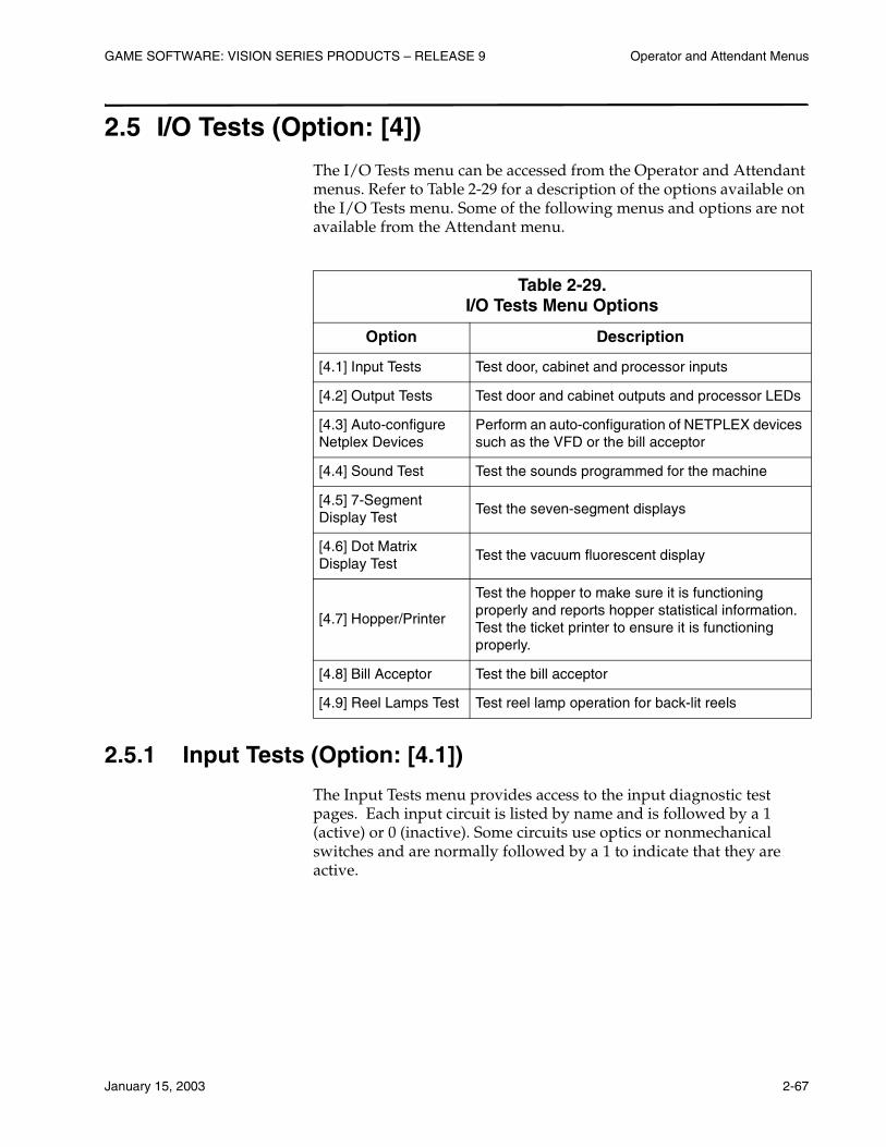
GAME SOFTWARE: VISION SERIES PRODUCTS – RELEASE 9 Operator and Attendant Menus
January 15, 2003 2-67
2.5 I/O Tests (Option: [4])
The I/O Tests menu can be accessed from the Operator and Attendant menus. Refer to Table 2-29 for a description of the options available on the I/O Tests menu. Some of the following menus and options are not available from the Attendant menu.
2.5.1 Input Tests (Option: [4.1])
The Input Tests menu provides access to the input diagnostic test pages. Each input circuit is listed by name and is followed by a 1 (active) or 0 (inactive). Some circuits use optics or nonmechanical switches and are normally followed by a 1 to indicate that they are active.
Table 2-29. I/O Tests Menu Options
Option Description
[4.1] Input Tests Test door, cabinet and processor inputs
[4.2] Output Tests Test door and cabinet outputs and processor LEDs
[4.3] Auto-configure Netplex Devices
Perform an auto-configuration of NETPLEX devices such as the VFD or the bill acceptor
[4.4] Sound Test Test the sounds programmed for the machine
[4.5] 7-Segment Display Test
Test the seven-segment displays
[4.6] Dot Matrix Display Test
Test the vacuum fluorescent display
[4.7] Hopper/Printer
Test the hopper to make sure it is functioning properly and reports hopper statistical information. Test the ticket printer to ensure it is functioning properly.
[4.8] Bill Acceptor Test the bill acceptor
[4.9] Reel Lamps Test Test reel lamp operation for back-lit reels
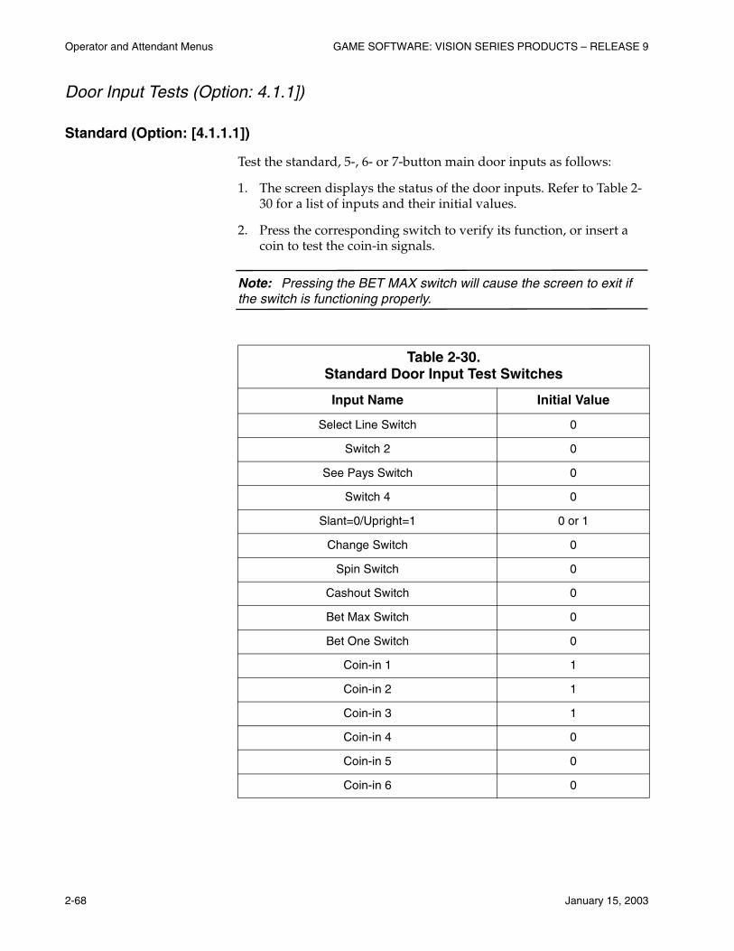
Operator and Attendant Menus GAME SOFTWARE: VISION SERIES PRODUCTS – RELEASE 9
2-68 January 15, 2003
Door Input Tests (Option: 4.1.1])
Standard (Option: [4.1.1.1])
Test the standard, 5-, 6- or 7-button main door inputs as follows:
1. The screen displays the status of the door inputs. Refer to Table 2-30 for a list of inputs and their initial values.
2. Press the corresponding switch to verify its function, or insert a coin to test the coin-in signals.
Note: Pressing the BET MAX switch will cause the screen to exit if the switch is functioning properly.
Table 2-30. Standard Door Input Test Switches
Input Name Initial Value
Select Line Switch 0
Switch 2 0
See Pays Switch 0
Switch 4 0
Slant=0/Upright=1 0 or 1
Change Switch 0
Spin Switch 0
Cashout Switch 0
Bet Max Switch 0
Bet One Switch 0
Coin-in 1 1
Coin-in 2 1
Coin-in 3 1
Coin-in 4 0
Coin-in 5 0
Coin-in 6 0
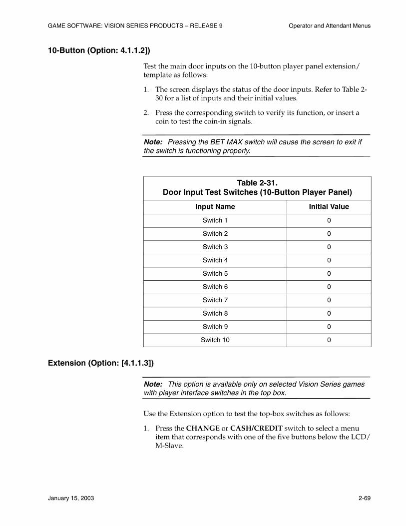
GAME SOFTWARE: VISION SERIES PRODUCTS – RELEASE 9 Operator and Attendant Menus
January 15, 2003 2-69
10-Button (Option: 4.1.1.2])
Test the main door inputs on the 10-button player panel extension/template as follows:
1. The screen displays the status of the door inputs. Refer to Table 2-30 for a list of inputs and their initial values.
2. Press the corresponding switch to verify its function, or insert a coin to test the coin-in signals.
Note: Pressing the BET MAX switch will cause the screen to exit if the switch is functioning properly.
Extension (Option: [4.1.1.3])
Note: This option is available only on selected Vision Series games with player interface switches in the top box.
Use the Extension option to test the top-box switches as follows:
1. Press the CHANGE or CASH/CREDIT switch to select a menu item that corresponds with one of the five buttons below the LCD/M-Slave.
Table 2-31. Door Input Test Switches (10-Button Player Panel)
Input Name Initial Value
Switch 1 0
Switch 2 0
Switch 3 0
Switch 4 0
Switch 5 0
Switch 6 0
Switch 7 0
Switch 8 0
Switch 9 0
Switch 10 0
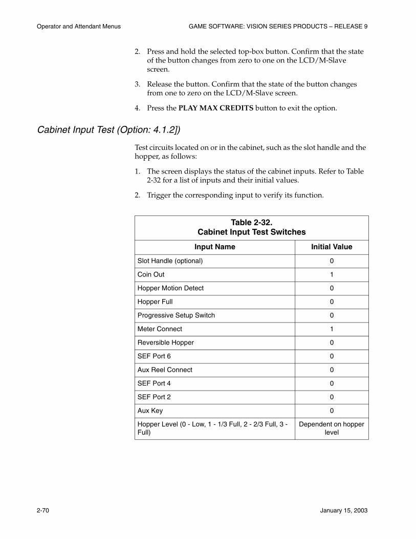
Operator and Attendant Menus GAME SOFTWARE: VISION SERIES PRODUCTS – RELEASE 9
2-70 January 15, 2003
2. Press and hold the selected top-box button. Confirm that the state of the button changes from zero to one on the LCD/M-Slave screen.
3. Release the button. Confirm that the state of the button changes from one to zero on the LCD/M-Slave screen.
4. Press the PLAY MAX CREDITS button to exit the option.
Cabinet Input Test (Option: 4.1.2])
Test circuits located on or in the cabinet, such as the slot handle and the hopper, as follows:
1. The screen displays the status of the cabinet inputs. Refer to Table 2-32 for a list of inputs and their initial values.
2. Trigger the corresponding input to verify its function.
Table 2-32. Cabinet Input Test Switches
Input Name Initial Value
Slot Handle (optional) 0
Coin Out 1
Hopper Motion Detect 0
Hopper Full 0
Progressive Setup Switch 0
Meter Connect 1
Reversible Hopper 0
SEF Port 6 0
Aux Reel Connect 0
SEF Port 4 0
SEF Port 2 0
Aux Key 0
Hopper Level (0 - Low, 1 - 1/3 Full, 2 - 2/3 Full, 3 - Full)
Dependent on hopper level
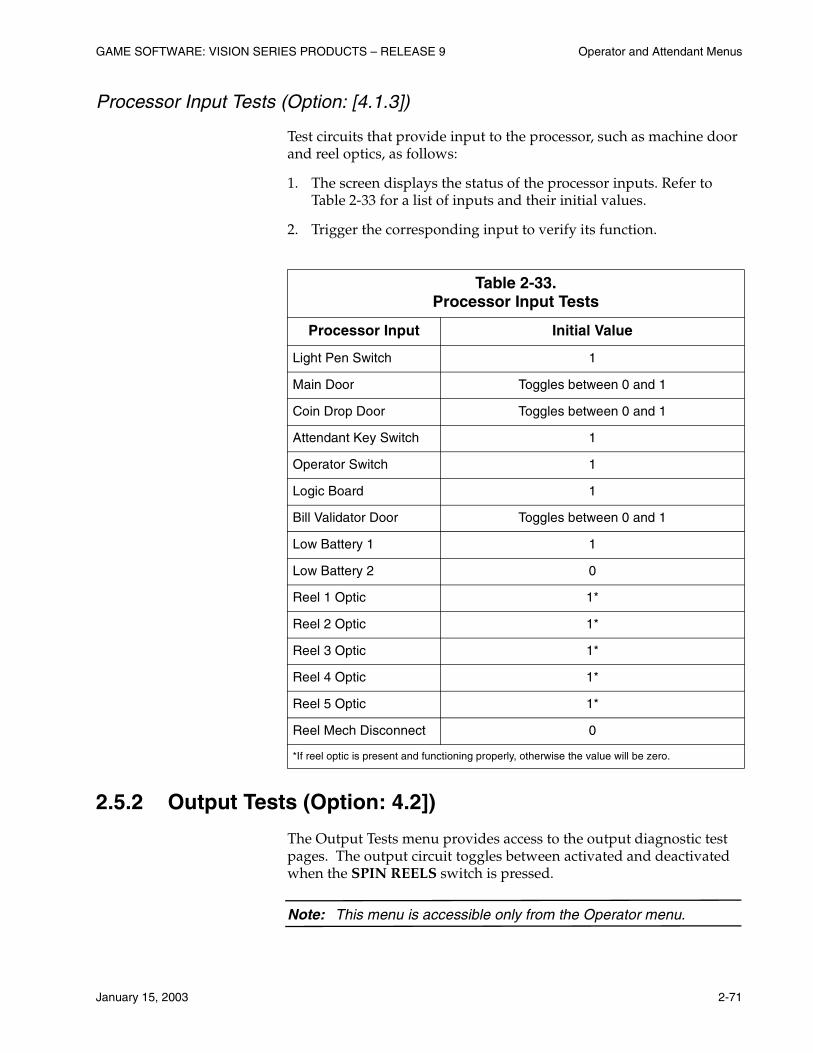
GAME SOFTWARE: VISION SERIES PRODUCTS – RELEASE 9 Operator and Attendant Menus
January 15, 2003 2-71
Processor Input Tests (Option: [4.1.3])
Test circuits that provide input to the processor, such as machine door and reel optics, as follows:
1. The screen displays the status of the processor inputs. Refer to Table 2-33 for a list of inputs and their initial values.
2. Trigger the corresponding input to verify its function.
2.5.2 Output Tests (Option: 4.2])
The Output Tests menu provides access to the output diagnostic test pages. The output circuit toggles between activated and deactivated when the SPIN REELS switch is pressed.
Note: This menu is accessible only from the Operator menu.
Table 2-33. Processor Input Tests
Processor Input Initial Value
Light Pen Switch 1
Main Door Toggles between 0 and 1
Coin Drop Door Toggles between 0 and 1
Attendant Key Switch 1
Operator Switch 1
Logic Board 1
Bill Validator Door Toggles between 0 and 1
Low Battery 1 1
Low Battery 2 0
Reel 1 Optic 1*
Reel 2 Optic 1*
Reel 3 Optic 1*
Reel 4 Optic 1*
Reel 5 Optic 1*
Reel Mech Disconnect 0
*If reel optic is present and functioning properly, otherwise the value will be zero.

Operator and Attendant Menus GAME SOFTWARE: VISION SERIES PRODUCTS – RELEASE 9
2-72 January 15, 2003
Door Output Test (Option: [4.2.1])
Standard Door Output Test (Option: [4.2.1.1])
Test the following 5-, 6-, or 7-button main door outputs on standard switch panels:
• Select Line Switch Lamp
• Switch 2 Lamp
• See Pays Switch Lamp
• Switch 4 Lamp
• Change Switch Lamp
• Spin Switch Lamp
• Cashout Switch Lamp
• Bet Max Switch Lamp
• Bet One Switch Lamp
• Coin Lockout
• Coin Diverter
Use the following steps to test door outputs:
1. Press the CHANGE and CASH/CREDIT switches to navigate through the list of outputs.
2. Press the SPIN REELS switch to run a test, or press the PLAY MAX CREDITS switch to exit the screen.
10-Button (Option: [4.2.1.2])
Test the switch lamps 1 through 10 on the 10-button switch panel extension/template as follows:
1. Press the CHANGE and CASH/CREDIT switches to navigate through the list of outputs.
2. Press the SPIN REELS switch to run a test, or press the PLAY MAX CREDITS switch to exit the screen.
GAME SOFTWARE: VISION SERIES PRODUCTS – RELEASE 9 Operator and Attendant Menus
January 15, 2003 2-73
Paylines Test (Option: [4.2.1.3])
Test payline 1 through 9 outputs on the main door as follows:
1. Press the CHANGE and CASH/CREDIT switches to navigate through the list of outputs.
2. Press the SPIN REELS switch to run a test, or press the PLAY MAX CREDITS switch to exit the screen.
Extension (Option: [4.2.1.4])]
Note: This option is available only on selected Vision Series games with player interface switches in the top box.
Use the Extension option to test the top-box switches as follows:
1. Press the CHANGE or CASH/CREDIT switch to select a menu item that corresponds with one of the five buttons below the LCD/M-Slave.
2. Press the SPIN REELS switch to run a test. Confirm that the selected switch lights properly.
3. Press the PLAY MAX CREDITS button to exit the option.
Cabinet Outputs Test (Option: [4.2.2])
Test the following output circuits located on or in the cabinet:
• Hopper Brake
• Hopper Safety
• Hopper Direction
• Jackpot
• Candle 1 Lamp
• Candle 2 Lamp
• Candle 3 Lamp
• Candle 4 Lamp
• Mechanical Meter 1
• Mechanical Meter 2
• Mechanical Meter 3

Operator and Attendant Menus GAME SOFTWARE: VISION SERIES PRODUCTS – RELEASE 9
2-74 January 15, 2003
• Mechanical Meter 4
• Mechanical Meter 5
• Mechanical Meter 6
• Bell
• Slot Handle Release
Use the following steps to test cabinet outputs:
1. Press the CHANGE and CASH/CREDIT switches to navigate through the list of outputs.
2. Press the SPIN REELS switch to run a test, or press the PLAY MAX CREDITS switch to exit the screen.
Processor Output Test (Option: [4.2.3])
Test the processor LEDs using the following procedure:
1. The screen displays the initial values of the LEDs. Press the CHANGE and CASH/CREDIT switches to navigate through the list.
2. Press the SPIN REELS to run a test, or press the PLAY MAX CREDITS to exit the screen.
2.5.3 Auto-Configure NETPLEX™ Devices (Option: [4.3])
Note: This screen is accessible only from the Operator menu.
Use the Auto-configure Netplex Devices screen to automatically configure the NETPLEX devices installed in the machine, such as the bill validator, printer, VFD and spectrum display.
1. Use the CHANGE and CASH/CREDIT switches to navigate forward and backward through the list of installed devices.
2. Press the SPIN REELS switch to run the autoconfiguration for the selected device. The screen indicates that the autoconfiguration is in progress.
3. Press the PLAY MAX CREDITS switch to exit the screen.

GAME SOFTWARE: VISION SERIES PRODUCTS – RELEASE 9 Operator and Attendant Menus
January 15, 2003 2-75
2.5.4 Sound Test (Option: 4.4])
Sound Test (Option: [4.4.1])
Test the standard game sounds as follows:
1. The screen displays a list of sounds that can be tested. Press the CHANGE and CASH/CREDIT switches to navigate through the list of sounds.
2. Press the SPIN REELS switch to play the selected sound.
3. Press the PLAY MAX CREDITS switch to exit the screen.
MMLB Sound File Test (Option: [4.4.2])
Use the MMLB Sound File Test option to test the WAV file theme sound on the Multimedia Lite Board as follows:
1. The screen displays a list of sounds that can be tested. Press the CHANGE and CASH/CREDIT switches to navigate through the list of sounds.
2. Press the SPIN REELS switch to play the selected sound.
3. Press the PLAY MAX CREDITS switch to exit the screen.
2.5.5 Display Test (Option: [4.5])
Test all segments of the seven-segment display that appear in the Winner Paid, Credits, and Coins Played windows.
Press the SPIN REELS switch to start and stop the test. During test execution, the segments of each display light up in sequence. Press the BET MAX CREDITS switch to exit the screen.
2.5.6 Dot Matrix (VFD) Display Test (Option: [4.6])
Test dot matrix function on the VFD. The VFD is tested as follows:
• All dots ON
• All dots OFF
• Horizontal sweep
• Vertical sweep
Press the SPIN REELS switch to start or pause the test. Press the PLAY MAX CREDITS switch to exit the screen.
Operator and Attendant Menus GAME SOFTWARE: VISION SERIES PRODUCTS – RELEASE 9
2-76 January 15, 2003
2.5.7 Hopper/Printer (Option: [4.7])
The Hopper/Printer Test menu tests hopper payout and proper functioning of the ticket printer.
Note: This menu is accessible only from the Operator menu.
Hopper Test (Option: [4.7.1])
If the hopper is functioning properly, it will pay out ten coins.
Turn the attendant key when prompted, and press the SPIN REELS switch to test hopper operation.
Print Test (Option: [4.7.2])
Note: This option is not available if the ticket printer is disabled.
Use the Print Test screen to print a sample ticket, or to eject a blank ticket from the printer as follows:
1. Press the CHANGE and CASH/CREDIT switches to navigate through the list of tests.
2. Press the SPIN REELS switch to run the selected printer test.
3. Press the PLAY MAX CREDITS switch to exit the screen.
2.5.8 Bill Acceptor (Option: [4.8])
The following tests verify that the bill acceptor hardware and software are functioning properly.
Note: This menu is accessible only from the Operator menu.
Bill Test (Option: [4.8.1])
The bill validator can be set to accept and stack or scan and reject a test bill. Use the following steps to test the bill acceptor:
1. Press the CHANGE and CASH/CREDIT switches to navigate through the list of tests. “Bill rejection” is the default test.
GAME SOFTWARE: VISION SERIES PRODUCTS – RELEASE 9 Operator and Attendant Menus
January 15, 2003 2-77
2. Press the SPIN REELS switch to run the selected test:
• To test bill rejection, insert a bill into the acceptor. The acceptor scans and rejects the bill.
• To test bill acceptance, insert a bill into the acceptor. The acceptor stacks the bill. The bill validator door must be open to run this test.
The value of the test bill is displayed on the VFD and LCD, if possible.
3. Press the PLAY MAX CREDITS switch to exit the screen.
CRC Checks (Option: [4.8.2])
Use the Cyclic Redundancy Check menu to audit the bill validator firmware. The 4-digit and 8-digit CRC checks can be accessed from this menu.
4-Digit CRC (Option: 4.8.2.1]) and 8-Digit CRC (Option: [4.8.2.2])
1. The screen provides edit fields for the program address and seed. Press the CHANGE and CASH/CREDIT switches to navigate between the fields.
2. Press the SPIN REELS switch to enter a value into the selected field.
a. Press the CHANGE and CASH/CREDITS switches to change a digit in the selected field.
b. Press the SPIN REELS switch to reset the field to its original value.
c. Press the PLAY MAX CREDITS switch to exit the field.
3. Navigate to the Calculate CRC field and press the SPIN REELS switch to run the test. The screen displays the result.
4. Press the PLAY MAX CREDITS switch to exit the screen.
Operator and Attendant Menus GAME SOFTWARE: VISION SERIES PRODUCTS – RELEASE 9
2-78 January 15, 2003
2.5.9 Bonus Device Test (Option: [4.9])
Top Lamps Test (Option: [4.9.1])
The Top Lamps Test screen tests the top lamp operation on the light board. Press the SPIN REELS switch to start and stop the test. Press the PLAY MAX CREDITS switch to exit the test.
Note: This option is available only on WAP machines.
Regis Device Test (Option: [4.9.2])
The Regis Device Test option tests the top-box bonus device for the Regis’ Cash Club™ game. The test launches automatically. Press the SPIN REELS button to suspend the test. Press the PLAY MAX CREDITS button to exit the test.
Aux. Bonus Device Test (Option: [4.9.3])
Note: This menu item is available only if the machine is equipped with a NETPLEX bonus device in the top box, such as a ball dispenser.
The Aux. Bonus Device Test option tests ball-dispensing bonus devices. Press the SPIN REELS button to cycle through all of the balls in the container.
Bonus Lamps Test (Option: [4.9.4])
The Bonus Lamps Test option tests top-box lamp operation. Press the SPIN REELS button to trigger illumination of the lamps in succession. When all of the lamps have been tested, all of the lamps are turned on for one second. The test ends when the lamps are turned off. The test sequence automatically repeats. Press the SPIN REELS button to suspend the test, or press the PLAY MAX CREDITS button to end the test.

GAME SOFTWARE: VISION SERIES PRODUCTS – RELEASE 9 Operator and Attendant Menus
January 15, 2003 2-79
Top Box Device Tests (Option: [4.9.5])
Dice LED Device Test (Option: [4.9.4.1])
Use the Dice LED Device Test option to test the lights surrounding the top-box dice. Press the SPIN REELS button to to trigger illumination of the lights. The lights around each die illuminate in a clockwise sequence. Press the SPIN REELS button to suspend the test, or press the PLAY MAX CREDITS button to end the test.
Seven Segment Test (Option: [4.9.4.2])
Use the Seven Segment Test to test the 7-segment displays in the top-box bonus device. The test executes a series of display patterns on the displays. Press the SPIN REELS button to suspend the test, or press the PLAY MAX CREDITS button to end the test.
LED Test (Option: [4.9.4.3])
Use the LED Test option to test the bonus level indicator LEDs in the top-box bonus device. Press the SPIN REELS button to trigger illumination of the LEDs from bottom to top. Press the SPIN REELS button to suspend the test, or press the PLAY MAX CREDITS button to end the test.
Reel Backlights (Option: [4.9.4.4])
Use the Reel Backlights option to test the backlit reels in the top box. Press the SPIN REELS button to trigger simultaneous illumination of the lamps at four levels of intensity – off, low, medium and high. Press the SPIN REELS button to suspend the test, or press the PLAY MAX CREDITS button to end the test.
Reel Tivolis (Option: [4.9.4.5])
Use the Reel Tivolis option to test the Tivoli light strands surrounding each reel in the top box. Press the SPIN REELS button trigger simultaneous flashing of the lights, followed by a bottom-to-top sequence. Press the SPIN REELS button to suspend the test, or press the PLAY MAX CREDITS button to end the test.
Reel Payline Indicators (Option: [4.9.4.6])
Use the Reel Payline Indicator option to test the lamp operation on the payline indicator device, typically an arrow, for each reel in the top box. Pres the SPIN REELS button to trigger simultaneous flashing of the lights. Press the SPIN REELS button to suspend the test, or press the PLAY MAX CREDITS button to end the test.

Operator and Attendant Menus GAME SOFTWARE: VISION SERIES PRODUCTS – RELEASE 9
2-80 January 15, 2003
Bonus Reel Light Ring Test (Option: [4.9.5])
Note: This option is available only on four-reel games.
Use the Bonus Reel Light Ring Test option to test the operation of the LEDs surrounding the fourth reel on the Big Times Pay game. Press the SPIN REELS button to illuminate the LEDs in a clockwise sequence. Press the SPIN REELS button to suspend the test, or press the PLAY MAX CREDITS button to end the test.
Barcrest Lamps Test (Option: [4.9.5])
Note: This option is available only on machines with Barcrest top boxes.
Use the Barcrest Lamps Test option to test the lamp operation in the top box. Press the SPIN REELS button to trigger illumination of the lamps in sequence, followed by a one-second illumination of all of the lamps at once. The lamps are then turned off. The test repeats automatically. Press the SPIN REELS button to suspend the test, or press the PLAY MAX CREDITS button to end the test.
Barcrest LEDs Test (Option:[4.9.6])
Note: This option is available only on machines with Barcrest top boxes.
Use the Barcrest LEDs Test option to test operation of the 7-segment displays in the top box. The test executes a series of display patterns on the displays. Press the SPIN REELS button to suspend the test, or press the PLAY MAX CREDITS button to end the test.
2.5.10 Reel Lamps Test (Option: [4.10])
The Reel Lamps Test screen tests the reel lamp operation for machines with backlit reels. Press the SPIN REELS switch to start and stop the test. Press the PLAY MAX CREDITS switch to exit the test.
GAME SOFTWARE: VISION SERIES PRODUCTS – RELEASE 9 Operator and Attendant Menus
January 15, 2003 2-81
2.6 Game Tests (Option: [5])
The Game Tests menu provides access to reel strip and paytable tests. Refer to Table 2-34 for a brief description of the available options.
Note: This menu is accessible only from the Operator menu.
2.6.1 Reel Strip Test (Option: [5.1])
The Reel Strip Test screen verifies that the symbols appearing on the reels are correct and that the reels spin to the correct stops as follows:
1. Turn the Attendant key when prompted. The reels move to the first stop.
2. Press the CHANGE and CASH/CREDIT switches to modify the reel stops.
3. Press the SPIN REELS switch to automatically cycle through the virtual stops in numeric order. Press the SPIN REELS switch again to pause the test.
4. Press the PLAY MAX CREDITS switch to exit the screen.
2.6.2 Base Paytable Test (Option: [5.2])
The Paytable Test screen verifies that the game is paying out the correct amounts. Use the following steps to run the test:
1. Turn the Attendant key when prompted.
2. Enter a reel stop number for each of the reels:
a. Press the CHANGE switch to navigate between reels.
Table 2-34. Game Tests Menu Options
Option Description
[5.1] Reel Strip TestVerify that the symbols appearing on the reels are correct and that the reels spin to the correct stops
[5.2] Base Paytable Test
Verify payouts for any reel stop and wager combination
[5.3] Bonus Paytable Test
Test bonus devices used in WAP and standalone games
Operator and Attendant Menus GAME SOFTWARE: VISION SERIES PRODUCTS – RELEASE 9
2-82 January 15, 2003
b. Press the CASH/CREDIT switch to increment the reel stop number. The software limits these values to numbers between 1 and 22.
3. Press the SPIN REELS switch to position the reels in the requested combination. The VFD displays the award that is associated with the symbol combination. The cursor moves to the bet amount field.
4. Press the CHANGE or CASH/CREDIT switches to change the bet amount. The VFD and LCD display the win amount for the revised wager.
5. Press the SPIN REELS switch to run another test or the PLAY MAX CREDITS switch to exit the screen.
2.6.3 Bonus Device Test (Option: [5.3])
Select the Bonus Device Test option to confirm the values associated with virtual stops on machines with a bonus device in the top box and verify the accuracy of the game’s paytable.
Use the following steps to run the bonus device test:
1. Press the CASH/CREDIT switch to increment the virtual stop for the bonus device and press the CHANGE switch to decrement the virtual stop. The VFD displays the physical stop of the bonus device and the corresponding win amount.
2. If testing a wheel-based device, press the SPIN REELS switch to cause the wheel to spin to the indicated stop.
3. Press the PLAY MAX CREDITS switch to exit the screen.
GAME SOFTWARE: VISION SERIES PRODUCTS – RELEASE 9 Operator and Attendant Menus
January 15, 2003 2-83
2.7 Out of Service Mode (Option: [6])
Use the Out of Service mode to set the machine mode to “Out of Service,” “In Service” or “Reserved.” If the machine mode is “Out of Service” the LCD displays an “Out of Service” message. The machine cannot be played unless its mode is “In Service.” The Out of Service mode remains in effect until the mode is changed.

January 15, 2003 3-1
Section 3Key Chip Menus
The Key Chip menus allow setup of various sensitive machine and game parameters, and is available only after performing the key chip replacement procedure. Refer to Section 4.3 for detailed instructions.
Note: Specific software features vary depending upon jurisdiction. The information presented in this manual is intended to reflect all features available, but not necessarily those available in any specific jurisdiction.
Information in this section includes:
• Section 3.1, Key Chip Config I Menu (Option: [7.1]) – provides detailed instructions for the menus and options that are available on the Key Chip menu.
• Section 3.2, Key Chip Config II Menu Options (Option: [7.2]) – provides detailed instructions for the menus and options that are available on the Key Chip II menu.

Key Chip Menus GAME SOFTWARE: VISION SERIES PRODUCTS – RELEASE 9
3-2 January 15, 2003
3.1 Key Chip Config I Menu (Option: [7.1])
The options on the Key Chip Config menu vary by jurisdiction. The following options typically require the key chip and cannot be changed from the Operator menu. Refer to Table 3-1 for a brief description of the Key Chip Config menu options.
3.1.1 Denomination (Option: [7.1.1])
Note: This option is available only on non-WAP machines.
Select the Denomination option to set the machine’s denomination. The machine denomination setting determines how accepted bills and progressive values are converted to credits. The default value is zero.
Table 3-1. Key Chip Config Menu Options
Menu/Option Description
DenominationDeternine the game denomination when the machine is powered up for the first time.
Game Selection
Determine the game’s paytable.
Bonus MenuIf the base PROM supports standalone bonus games, select and configure the standalone bonus game.
Progressive/WAP System Setup
Configure features and levels for progressive games. The WAP System Setup menu is available only on WAP machines.
EFT Control Determine the different modes of EFT operation.
Machine Type Configure the machine type.
Token Setup Set the token value (not available in all jurisdictions).
Candle Stage Setup
Select the appropriate candle type for the machine (international version only).
Money Format
Set the bill acceptor currency symbol, thousand separator, and decimal separator (international version only).
OptionsConfigure hard meter monitoring options (international version only) and enable or disable player initiated cashouts of partial token credits.
GAME SOFTWARE: VISION SERIES PRODUCTS – RELEASE 9 Key Chip Menus
January 15, 2003 3-3
1. The current denomination is displayed. Press the SPIN REELS switch to edit the field.
2. Press the CHANGE and CASH/CREDIT switches to change the field value.
3. Press the PLAY MAX CREDITS switch to exit the screen and save the changes, or press the SPIN REELS switch to reset the field’s value.
Accounting Denomination (Option: [7.1.1.1])
Note: This option is not available if the game is configured only to accept multiples of the hopper denomination.
Use the Accounting Denomination option to change the denomination for meters displayed by the Terminal Master Money Accounting and Period Terminal Accounting Options.
1. Navigate through the list of settings using the CHANGE and CASH/CREDIT switches.
2. Press the PLAY MAX CREDITS switch to exit the screen and save the changes, or press the SPIN REELS switch to reset the value to the previous setting.
Coin Denomination (Option: [7.1.1.2])
Use the Coin Denomination option to determine how the machine converts accepted bills, tickets, EFT transations and progressive values to machine credits. For example, if the coin denomination is set to 25 cents, a dollar is converted to four credits on the credit meter.
1. The screen displays the current setting. Press the CHANGE switch to navigate between the digits.
2. Press the CASH/CREDIT switch to increment the current digit.
3. Press the SPIN REELS switch to reset the value to the previous setting, or press the PLAY MAX CREDITS switch to save the new setting and exit the screen.
Key Chip Menus GAME SOFTWARE: VISION SERIES PRODUCTS – RELEASE 9
3-4 January 15, 2003
Player Denomination (Option: [7.1.1.3])
Use the Player Denomination option to configure the denomination options available to the player.
Note: The denomination cannot be less than the accounting denomination.
If the game is configured only to accept multiples of the hopper denomination, the denomination must be a multiple of the hopper denomination.
1. Press the CHANGE and CASH/CREDIT switches to navigate through the list of denominations.
2. Press the PLAY MAX CREDITS switch to select the denomination or press the SPIN REELS switch to exit the screen.
3.1.2 Game Selection (Option: [7.1.2])
Use the Game Selection screen to determine the game’s paytable. The number of paytables available depends on the base PROM installed. This screen cannot be accessed if only one paytable is available.
Set the paytable using the following procedure:
1. Navigate through the list of values using the CHANGE and CASH/CREDIT switches.
2. Press the PLAY MAX CREDITS switch to exit the screen and save the changes, or press the SPIN REELS switch to reset the value to the previous setting.
3.1.3 Bonus Menu (Option: [7.1.3])
Bonus Game Configuration (Option: [7.1.3.1])
Note: This option is available only if the machine is configured for generic bonus games.
Select the Bonus Game Configuration option to select up to 10 standalone bonus games to associate with the base game. The types of bonus games available depend on the Base PROM used and the LCD program version. Use the following steps to configure bonus games:
1. Press the CHANGE and CASH/CREDIT switches to navigate through the list of bonus fields.
GAME SOFTWARE: VISION SERIES PRODUCTS – RELEASE 9 Key Chip Menus
January 15, 2003 3-5
2. Press the SPIN REELS switch to display the list of bonus games for the selected bonus field. Select a game using the following steps:
a. Press the CHANGE and CASH/CREDIT to navigate through the list of available bonus games.
b. Press the PLAY MAX CREDITS switch to select the bonus game, or press the SPIN REELS switch to reset the value.
3. Press the PLAY MAX CREDITS switch to exit the screen and save your changes.
View Bonus Game Settings (Option: [7.1.3.2])
Note: This option is available only if the machine is configured for generic bonus games.
Select the Bonus Game Settings option to configure bonus game parameters. If the parameter settings result in a payback percentage that is greater than the maximum allowed by the Key Chip, the payback area of the screen displays “---.--%” to indicate that the payback percentage is invalid. When this condition occurs, the parameters cannot be saved. Exiting the screen will restore the original bonus values.
Use the following steps to configure the bonus games:
1. Press the CHANGE and CASH/CREDIT switches to navigate through the list of parameters. Press the SPIN REELS switch to change the value of the desired parameter.
2. Press the CHANGE switch to select the digit to modify. Press the CASH/CREDIT switch to increment the digit’s value.
3. Press the SPIN REELS switch to revert to the parameter’s original value or press the PLAY MAX CREDITS switch to save the changes to the field.
4. Press PLAY MAX CREDITS to save the changes and exit the screen or press the SPIN REELS switch to revert to the original values.
Bonus Game Selection (Option: [7.1.3.3])
Note: This option is available only if the machine is configured for generic bonus games.
Select the Bonus Game Selection option to select one of 10 available bonus games.

Key Chip Menus GAME SOFTWARE: VISION SERIES PRODUCTS – RELEASE 9
3-6 January 15, 2003
Use the following steps to activate a bonus game:
1. Press the CHANGE and CASH/CREDIT switches to navigate through the list of bonus games.
The screen displays the highlighted game’s theoretical payback percentage. If the percentage exceeds the maximum allowed by the Key Chip, the screen displays “---.--%” to indicate that the payback percentage is invalid.
2. Press the PLAY MAX CREDITS switch to select the bonus game or press the SPIN REELS switch to exit the screen.
Global Setup (Option: [7.1.3.4])
This screen is enabled for games that support any of the global parameters. If a game-specific bonus game is installed, this screen allows the operator to set the User Input Timeout option, which determines the amount of time that the player has to push the SPIN REELS switch before the game automatically starts the non-linked bonus game.
Use the following procedure to configure the user input timeout:
1. If more than one item can be configured, press the CHANGE and CASH/CREDIT switches to navigate to the desired parameter.
2. Press the SPIN REELS switch to edit the selected parameter.
3. Press the CHANGE switch to move from one digit to another.
4. Press the CASH/CREDIT switch to increment the digit.
5. Press the PLAY MAX CREDITS switch to exit the field.
6. Press the PLAY MAX CREDITS switch to save the changes and exit the screen, or press the SPIN REELS switch to reset the settings to their original values.
System Bonus On/Off (Option: [7.1.3.5])
This screen enables or disables the SAS bonusing capability. To enable this option, the polling address must be set to 001. Enabling this option activates the bonus pays and multiple jackpot modes at the same time.
Use the following steps to enable or disable SAS bonusing:
1. Navigate through the list of values using the CHANGE and CASH/CREDIT switches.
GAME SOFTWARE: VISION SERIES PRODUCTS – RELEASE 9 Key Chip Menus
January 15, 2003 3-7
2. Press the PLAY MAX CREDITS switch to exit the screen and save the changes, or press the SPIN REELS switch to reset the value to the previous setting.
Link On/Off (Option: [7.1.3.6])
Note: This option is not available on WAP machines.
This screen enables or disables SAS link bonusing. To enable this option, the polling address must be set to 001. If disabled, the game ignores all link bonus messages.
Use the following steps to enable or disable SAS link bonusing:
1. Navigate through the list of values using the CHANGE and CASH/CREDIT switches.
2. Press the PLAY MAX CREDITS switch to exit the screen and save the changes, or press the SPIN REELS switch to reset the value to the previous setting.
Link Setup (Option: [7.1.3.7])
Note: This option is not available on WAP machines.
If the link-bonusing option is enabled, this screen allows the operator to set the following bonus parameters:
• Max Win – allows the operator to set the maximum number of credits for a win from a link bonus. The machine accepts link messages from the host as long as the amounts are less than this limit.
• Host Timeout – determines how long the game should wait for communication with the system before a link-down condition occurs.
• User Input Timeout – determines the amount of time the player has to push the SPIN REELS switch before the game automatically starts the link-bonus game.
Use the following steps to configure the link setup:
1. Navigate through the list of values using the CHANGE and CASH/CREDIT switches.
2. Press the PLAY MAX CREDITS switch to exit the screen and save the changes, or press the SPIN REELS switch to reset the value to the previous setting.

Key Chip Menus GAME SOFTWARE: VISION SERIES PRODUCTS – RELEASE 9
3-8 January 15, 2003
3.1.4 Progressive/WAP System Setup (Option: [7.1.4])
Controller Select (Option: [7.1.4.1])
Note: This option is available only on non-WAP machines.
Use the Controller Select option to associate a progressive controller with a progressive level using the following steps:
1. Press the CHANGE and CASH/CREDIT switches to navigate through the list of progressive levels. Press the SPIN REELS switch to select the level to configure.
2. Use the CHANGE and CASH/CREDIT switches to navigate through the list of available controllers:
• None
• SAS
• Link
• Stand-alone
Press the PLAY MAX CREDITS switch to select a controller and return to the progressive level list.
3. Press the PLAY MAX CREDITS switch to exit the screen and save the changes, or press the SPIN REELS switch to reset the levels to their previous configuration.
Confirm Paytable (Option: [7.1.4.1])
Note: This option is available only on WAP machines.
After a cold power up, a WAP machine’s paytable must be configured. The default value of “no paytable selected” will prevent the game from functioning.
For non-WAP games, configure the following information for each paytable:
• Limit Amount – the highest jackpot amount the player can win
• Current Amount – the current amount shown on the spectrum or progressive seven-segment display
• Add Percentage – percentage of the wager that is contributed toward the progressive jackpot

GAME SOFTWARE: VISION SERIES PRODUCTS – RELEASE 9 Key Chip Menus
January 15, 2003 3-9
• Base Amount – the amount the progressive jackpot resets to after a win
• The Current Amount and Base Amount cannot be set to a value higher than the Limit Amount.
Note: This information is recovered from EEPROM after all system errors, except a base PROM change.
Select the paytable to confirm the denomination and system name using the following steps:
1. Navigate through the list of values using the CHANGE and CASH/CREDIT switches.
2. For non-WAP games, use the following steps to set the paytable parameters:
a. Navigate through the list of settings using the CHANGE and CASH/CREDIT switches.
b. Press the SPIN REELS switch to edit a field.
c. Press the CHANGE switch to move from one digit to another within the field.
d. Press the CASH/CREDIT switch to increment the digit.
e. Press the PLAY MAX CREDITS switch to exit the field.
3. Press the PLAY MAX CREDITS switch to exit the screen and save the changes, or press the SPIN REELS switch to reset the value to the previous setting.
Level (x) (Option: [7.1.4.1.x])
Use the Level option to select a progressive controller:
• None
• SAS
• Link
• Stand-alone
1. Navigate through the list of settings using the CHANGE and CASH/CREDIT switches.
2. Press the PLAY MAX CREDITS switch to exit the screen and save the changes, or press the SPIN REELS switch to reset the value to the previous setting.
Key Chip Menus GAME SOFTWARE: VISION SERIES PRODUCTS – RELEASE 9
3-10 January 15, 2003
Progressive Display Setup (Option: [7.1.4.2])
Note: This option is available only on non-WAP machines.
Select the Progressive Display Setup option to enable or disable display of progressive amounts on the LCD. Progressive amounts are not displayed if a bonus game is enabled. Use the following steps to enable display of progressive amounts on the LCD:
1. Navigate through the list of values using the CHANGE and CASH/CREDIT switches.
2. Press the PLAY MAX CREDITS switch to exit the screen and save the changes, or press the SPIN REELS switch to reset the value to the previous setting.
Metering Units (Option: [7.1.4.2])
Note: This option is available only on WAP machines.
WAP money meters are sent to the CCOM in credits by default. Some configurations may require that these meters be in cents, enabling machines of different denominations to share the same progressive jackpots on one communications loop. Configure the parameter using the following steps:
1. Navigate through the list of values using the CHANGE and CASH/CREDIT switches.
2. Press the PLAY MAX CREDITS switch to exit the screen and save the changes, or press the SPIN REELS switch to reset the value to the previous setting.
Stand Alone Setup (Option: [7.1.4.3])
Note: This option is available only on non-WAP machines.
Select the paytable to configure the progressive levels for each standalone progressive game:
• Limit Amount – the highest jackpot amount the player can win
• Current Amount – the current amount shown on the spectrum or progressive seven-segment display
• Add Percentage – percentage of the wager that is contributed toward the progressive jackpot

GAME SOFTWARE: VISION SERIES PRODUCTS – RELEASE 9 Key Chip Menus
January 15, 2003 3-11
• Base Amount – the amount the progressive jackpot resets to after a win
Note: The Current Amount and Base Amount cannot be set to a value higher than the Limit Amount.
Use the following steps to configure each level:
1. Navigate through the list of values using the CHANGE and CASH/CREDIT switches.
2. Press the SPIN REELS switch to edit a field.
3. Press the CHANGE switch to move from one digit to another within the field.
4. Press the CASH/CREDIT switch to increment the digit.
5. Press the PLAY MAX CREDITS switch to exit the field.
6. Press the PLAY MAX CREDITS switch to exit the screen and save the changes, or press the SPIN REELS switch to reset the value to the previous setting.
SAS Progressive Group (non-WAP) (Option: [7.1.4.5])
Select the SAS Progressive Group option to associate the game’s progressive levels to a SAS host using the following steps:
1. Press the SPIN REELS switch to edit the field.
2. Press the CHANGE switch to move from one digit to another.
3. Press the CASH/CREDIT switch to increment the digit.
4. Press the PLAY MAX CREDITS switch to exit the field.
5. Press the PLAY MAX CREDITS switch to save the changes and exit the screen, or press the SPIN REELS switch to reset the settings to their original values.
3.1.5 Electronic Funds Transfer (EFT) Control (Option: 7.1.5])
The EFT Control screen sets the mode of EFT Operation:
• EFT disabled – turn off EFT (default value)
• EFT SAS controller – allows EFT via the SAS host
• EFT Bally controller – allows EFT via the Bally host
Key Chip Menus GAME SOFTWARE: VISION SERIES PRODUCTS – RELEASE 9
3-12 January 15, 2003
Use the following steps to configure the EFT controller:
1. Navigate through the list of values using the CHANGE and CASH/CREDIT switches.
2. Press the PLAY MAX CREDITS switch to exit the screen and save the changes, or press the SPIN REELS switch to reset the value to the previous setting.
3.1.6 Machine Type (Option: [7.1.6])
The machine type must be set to slant-top or upright following a cold power up. If the option selected does not match the hardware used, the machine will tilt.
Use the following steps to configure the machine type:
1. Navigate through the list of values using the CHANGE and CASH/CREDIT switches.
2. Press the PLAY MAX CREDITS switch to exit the screen and save the changes, or press the SPIN REELS switch to reset the value to the previous setting.
3.1.7 Tokenization (Option: 7.1.7)
Token Setup (Option: [7.1.7.1])
Note: This option is not available in all jurisdictions. A value greater than one forces the game into credit mode and may change the hopper limit.
Use the Token Setup screen to set the credit value associated with a token. Valid values are from 1 to 100. Set the token value using the following steps:
1. Press the SPIN REELS switch to edit the field.
2. Press the CHANGE switch to navigate between digits, or press the CASH/CREDIT switch to increment the current digit.
3. Press the PLAY MAX CREDITS switch to save the setting and exit the screen, or press the SPIN REELS switch to reset the value.
GAME SOFTWARE: VISION SERIES PRODUCTS – RELEASE 9 Key Chip Menus
January 15, 2003 3-13
Partial Token Payout (Option: [7.1.7.2])
Note: This option is available only with the international version PROM.
Select the Partial Token Payout option to enable or disable player-initiated cashouts of partial token credits. This parameter’s default setting is enabled. The following conditions apply:
• If the option is enabled for a machine with a hopper-only configuration, partial token credits are hand paid.
• If the option is disabled, partial token payouts are not allowed.
• If the machine is configured with a ticket printer, partial token payouts are enabled automatically. Player-initiated cashouts for partial token credits will be paid by ticket.
• If the SAS EFT function is enabled, the machine will upload the partial token credits to the host.
Use the following steps to configure partial token payouts:
1. Navigate through the list of settings using the CHANGE and CASH/CREDIT switches.
2. Press the PLAY MAX CREDITS switch to exit the screen and save the changes, or press the SPIN REELS switch to reset the value to the previous setting.
3.1.8 Candle Stage Setup (Option: 7.1.8])
Note: This option is available only with the international version PROM, and it does not apply to WAP games.
This screen allows selection of the appropriate candle type for the machine. To set the candle type, use the following steps:
1. Navigate through the list of values using the CHANGE and CASH/CREDIT switches.
2. Press the PLAY MAX CREDITS switch to exit the screen and save the changes, or press the SPIN REELS switch to reset the value to the previous setting.
Key Chip Menus GAME SOFTWARE: VISION SERIES PRODUCTS – RELEASE 9
3-14 January 15, 2003
3.1.9 Money Format (Option: [7.1.9])
Note: This option is available only with the international version PROM, and it does not apply to WAP games.
Use the Money Format screen to set the bill acceptor currency symbol, thousand separator, and decimal separator. Use the following steps to configure the money format:
1. Press the CHANGE and CASH/CREDIT switches to navigate through the available fields – symbol, 1,000s indicator and decimal separator.
2. Press the SPIN REELS switch to enter the desired field.
3. To set the currency symbol:
a. Press the CHANGE switch to navigate through the positions in the field.
b. Press the CASH/CREDIT switch to change the selected character.
c. Press the SPIN REELS switch to reset the field, or press the PLAY MAX CREDITS switch to exit the field and save the changes.
4. To set the 1,000s indicator:
a. Press the CHANGE and CASH/CREDIT switches to toggle the separator value between the available options.
b. Press the SPIN REELS switch to reset the field or, press the PLAY MAX CREDITS switch to exit the field and save the changes.
5. To set the decimal separator:
a. Press the CHANGE and CASH/CREDIT switches to toggle the separator value between the available options.
b. Press the SPIN REELS switch to reset the field or, press the PLAY MAX CREDITS switch to exit the field and save the changes.
6. Press the PLAY MAX CREDITS switch to save the changes and exit the screen, or press the SPIN REELS switch to reset the values for all fields.

GAME SOFTWARE: VISION SERIES PRODUCTS – RELEASE 9 Key Chip Menus
January 15, 2003 3-15
3.1.10 Options (Option: 7.1.10])
The Options screen allows the operator to select hard meter monitoring options:
1. Press the CHANGE and CASH/CREDIT switches to navigate through the options.
2. Press the SPIN REELS switch to enter the selected screen.
Hard Meters (Option: [7.1.10.1])
Note: This option is available only with the international version PROM, and it does not apply to WAP games.
Use the Hard Meters screen to select hard meter monitoring options for the Coin Drop mechanical meter. The following settings are available:
• Coins only – international jurisdictions
• Coins and bills – all other jurisdictions
Use the following steps to set the hard meter monitoring options:
1. Navigate through the list of values using the CHANGE and CASH/CREDIT switches.
2. Press the PLAY MAX CREDITS switch to exit the screen and save the changes, or press the SPIN REELS switch to reset the value to the previous setting.
Coin-In (Option: [7.1.10.2])
Note: This option is available only with the international version PROM, and it does not apply to WAP games.
The Coin-In screen sets the machine to one of the following coin-in options:
• Coins to game only – coins inserted after the machine exceeds the maximum bet are returned to the player
• Coins to game and credit – coins inserted after the machine exceeds the maximum bet will be added to the credit meter until the machine exceeds the credit limit
• Coins to credit only – all coins inserted will be added to the credit meter

Key Chip Menus GAME SOFTWARE: VISION SERIES PRODUCTS – RELEASE 9
3-16 January 15, 2003
To set the coin-in option, use the following steps:
1. Navigate through the list of settings using the CHANGE and CASH/CREDIT switches.
2. Press the PLAY MAX CREDITS switch to exit the screen and save the changes, or press the SPIN REELS switch to reset the value to the previous setting.
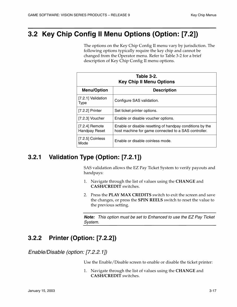
GAME SOFTWARE: VISION SERIES PRODUCTS – RELEASE 9 Key Chip Menus
January 15, 2003 3-17
3.2 Key Chip Config II Menu Options (Option: [7.2])
The options on the Key Chip Config II menu vary by jurisdiction. The following options typically require the key chip and cannot be changed from the Operator menu. Refer to Table 3-2 for a brief description of Key Chip Config II menu options.
3.2.1 Validation Type (Option: [7.2.1])
SAS validation allows the EZ Pay Ticket System to verify payouts and handpays:
1. Navigate through the list of values using the CHANGE and CASH/CREDIT switches.
2. Press the PLAY MAX CREDITS switch to exit the screen and save the changes, or press the SPIN REELS switch to reset the value to the previous setting.
Note: This option must be set to Enhanced to use the EZ Pay Ticket System.
3.2.2 Printer (Option: [7.2.2])
Enable/Disable (option: [7.2.2.1])
Use the Enable/Disable screen to enable or disable the ticket printer:
1. Navigate through the list of values using the CHANGE and CASH/CREDIT switches.
Table 3-2. Key Chip II Menu Options
Menu/Option Description
[7.2.1] Validation Type
Configure SAS validation.
[7.2.2] Printer Set ticket printer options.
[7.2.3] Voucher Enable or disable voucher options.
[7.2.4] Remote Handpay Reset
Enable or disable resetting of handpay conditions by the host machine for game connected to a SAS controller.
[7.2.5] Coinless Mode
Enable or disable coinless mode.

Key Chip Menus GAME SOFTWARE: VISION SERIES PRODUCTS – RELEASE 9
3-18 January 15, 2003
2. Press the PLAY MAX CREDITS switch to exit the screen and save the changes, or press the SPIN REELS switch to reset the value to the previous setting.
Handpay Receipts (Option: [7.2.2.2])
Use the Handpay Receipts screen to enable or disable printing of receipts for jackpots and hand pays.
Note: When this menu item is enabled on a non-WAP game, the machine does not print tickets for progressive jackpots.
For WAP games, the machine prints a ticket with a zero amount under some circumstances, such as a game with a non-cash prize.
1. Navigate through the list of values using the CHANGE and CASH/CREDIT switches.
2. Press the PLAY MAX CREDITS switch to exit the screen and save the changes, or press the SPIN REELS switch to reset the value to the previous setting.
3.2.3 Voucher (Option: [7.2.3])
Use the Voucher screen to enable or disable ticket redemption by the machine:
1. Navigate through the list of values using the CHANGE and CASH/CREDIT switches.
2. Press the PLAY MAX CREDITS switch to exit the screen and save the changes, or press the SPIN REELS switch to reset the value to the previous setting.
3.2.4 Remote Handpay Reset (Option: [7.2.4])
Note: This option is not available for WAP or stand-alone WAP games.
Use the Remote Handpay reset option to enable or disable resetting of the machine from the SAS host after the machine enters a hand pay condition.
1. Navigate through the list of values using the CHANGE and CASH/CREDIT switches.
GAME SOFTWARE: VISION SERIES PRODUCTS – RELEASE 9 Key Chip Menus
January 15, 2003 3-19
2. Press the PLAY MAX CREDITS switch to exit the screen and save the changes, or press the SPIN REELS switch to reset the value to the previous setting.
3.2.5 Coinless Mode (Option: [7.2.5])
Use the Coinless option to enable or disable coinless mode. When the machine is in coinless mode, the hopper and coin acceptor are disabled. All money-in and money-out handling is is performed via EFT transactions.
Note: The coinless mode can only be enabled when the machine is connected to a SAS controller.
Use the following steps to enable or disable coinless mode:
1. Navigate through the list of values using the CHANGE and CASH/CREDIT switches.
2. Press the PLAY MAX CREDITS switch to exit the screen and save the changes, or press the SPIN REELS switch to reset the value to the previous setting.

January 15, 2003 4-1
Section 4IC Chip and Flash Memory Card Procedures
This section describes key chip setup procedures available as an option in the Operator Menu in Vision Series software.
Information in this section includes:
• Section 4.1, IC Chip Replacement – describes procedures to follow when replacing the IC chips on the processor board.
• Section 4.2, Sound SIMM Board Replacement – provides procedures for removing and installing the sound SIMM board on processor boards that support stereo sound.
• Section 4.3, Key Chip Procedure – provides procedures for installing the key chip to access key chip setup options.
• Section 4.4, Clear Chip Procedure – provides procedures for using clear chips to clear RAM, EEPROM or both.
• Section 4.5, Flash Memory Cards – explains use of flash memory cards used in the LCD for bonus games and customized attract mode displays.
• Section 4.6, Game Program Change – provides procedures for changing game programs.

IC Chip and Flash Memory Card Procedures GAME SOFTWARE: VISION SERIES PRODUCTS – RELEASE 9
4-2 January 15, 2003
4.1 IC Chip Replacement
To remove or install integrated circuit (IC) chips on the processor board, see Figures 4-1 and 4-2, and proceed as follows.
Note: Check with state and local laws, and record the accounting data before removing game program chips. Chip removal clears all current accounting data.
For jumper locations on the processor board, see the processor (video controller) board schematic in the appropriate electronic diagrams and parts manual.
Figure 4-1. Component Locations, Vision Processor Board for Stereo Sound (p/n 755-105-0X)
00000042-111700
MULTIMEDIA LITEBOARD
SOUND SIMM
J1 MOTHERBOARD
J2 MOTHERBOARD
U17 REELDATA
U21 BASEPROM
U46 GAME PROM(GME2)
U19 GAME PROM(GME1)
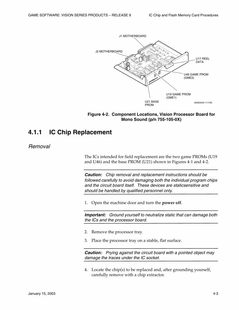
GAME SOFTWARE: VISION SERIES PRODUCTS – RELEASE 9 IC Chip and Flash Memory Card Procedures
January 15, 2003 4-3
Figure 4-2. Component Locations, Vision Processor Board for Mono Sound (p/n 755-105-0X)
4.1.1 IC Chip Replacement
Removal
The ICs intended for field replacement are the two game PROMs (U19 and U46) and the base PROM (U21) shown in Figures 4-1 and 4-2.
Caution: Chip removal and replacement instructions should be followed carefully to avoid damaging both the individual program chips and the circuit board itself. These devices are staticsensitive and should be handled by qualified personnel only.
1. Open the machine door and turn the power off.
Important: Ground yourself to neutralize static that can damage both the ICs and the processor board.
2. Remove the processor tray.
3. Place the processor tray on a stable, flat surface.
Caution: Prying against the circuit board with a pointed object may damage the traces under the IC socket.
4. Locate the chip(s) to be replaced and, after grounding yourself, carefully remove with a chip extractor.
00000043-111700
U17 REELDATA
U21 BASEPROM
U46 GAME PROM(GME2)
U19 GAME PROM(GME1)
J1 MOTHERBOARD
J2 MOTHERBOARD
IC Chip and Flash Memory Card Procedures GAME SOFTWARE: VISION SERIES PRODUCTS – RELEASE 9
4-4 January 15, 2003
Installation
1. Handling the computer chip only by the ends, visually align it by matching the orientation notch, located at one end of the chip, with the notched outline on the processor board.
Caution: If the computer chip is placed into its socket in the wrong direction or with one or more pins ("legs") out of position, the chip may be damaged when the machine power is turned on.
2. The two sets of "legs" on each computer chip are generally spread a little wider apart than the openings in the receptacle. If the legs appear too wide for the receptacle, adjust the alignment by using a chip installation tool of the correct size.
If an installation tool is not available, it may be possible to spring the legs into alignment by placing the chip on its side on a flat, nonconductive surface and gently tilting the chip just enough to bend all of the legs inward a little on each side.
3. When the chip is properly aligned, use gentle hand pressure to push it into the socket. Check both sides of the chip to be sure that all legs are engaged correctly before pushing all the way down into its seat.
4. Install the processor tray and lock into place.
5. Turn the machine power on. Refer to the Operator and Attendant Menu section of this manual for information about selecting programmable game options. Refer to the Troubleshooting: Game Machines manual to resolve any error messages that may appear on the video monitor.
6. Close and lock the machine door.
4.1.2 SS PROM Installation
Use the previous removal and installation instructions but insert this chip with the un-notched end closest to the unmarked end of socket U17. This chip has 28 pins but the socket has 32. See Figure 4-3 for details.
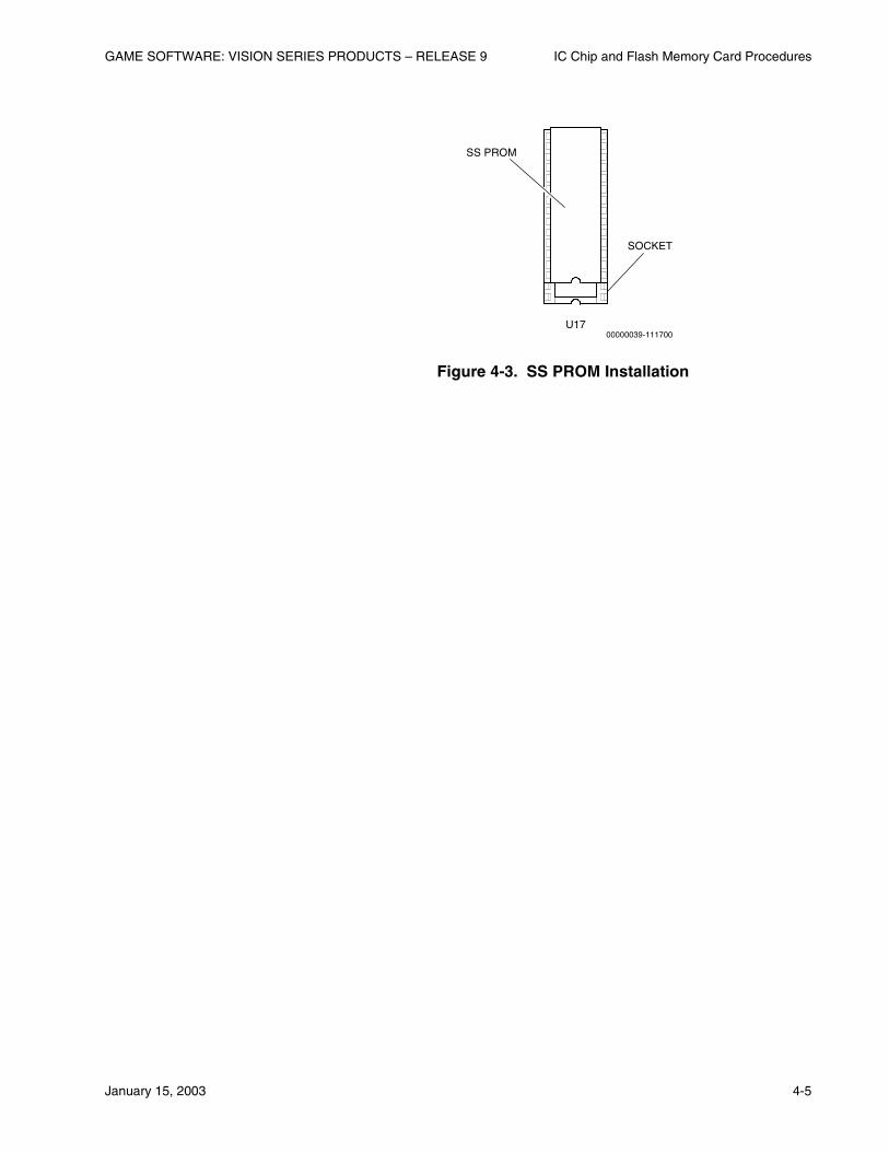
GAME SOFTWARE: VISION SERIES PRODUCTS – RELEASE 9 IC Chip and Flash Memory Card Procedures
January 15, 2003 4-5
Figure 4-3. SS PROM Installation
00000039-111700U17
SS PROM
SOCKET

IC Chip and Flash Memory Card Procedures GAME SOFTWARE: VISION SERIES PRODUCTS – RELEASE 9
4-6 January 15, 2003
4.2 Sound SIMM Board Replacement
The sound SIMM board contains the game sounds used in machines with stereo sound (refer to Figure 4-1). Each board is individually programmed for a specific game theme.
Note: This board must be replaced when changing game themes.
Removal
1. Press the small, metal tabs on both sides of the mount that holds the board, and the board releases.
2. Gently pull the board away from the mount.
Installation
1. Place the board into the mount at an angle and let it rest on the small, metal tabs.
2. Gently press down on the board until it snaps into place. The metal tabs will hold the board in place on the mount.

GAME SOFTWARE: VISION SERIES PRODUCTS – RELEASE 9 IC Chip and Flash Memory Card Procedures
January 15, 2003 4-7
4.3 Key Chip Procedure
Key chips are used to perform certain machine activities that are sensitive or require higher authority than the normal technician with access to the Operator menu. The key chip is required to change machine parameters such as the denomination, pay table or selected games. Follow this procedure to use the key chip.
Note: The key chip version must be compatible with the base EPROM on the processor board being changed.
1. Verify that there are no tilts, credits available, or games in progress on the machine.
2. Use the procedure in Section 4.1 to remove the Base EPROM from the processor board and replace it with the key chip.
3. Reinstall the processor board in the machine.
4. Turn the machine power on. When the key chip has been recognized, the two amber LEDs farthest from the operator switch light and stay lit.
• If the left LED lights, but not the right, then an error occurred. Repeat the procedure to verify that the key chip is correctly installed.
• If the right LED lights, but not the left, the key chip failed because the processor board identification does not match.
• If neither LED lights, the key chip is bad.
5. Turn the machine power off and replace the key chip with the base EPROM.
6. Reinstall the processor board in the machine.
7. Turn the machine power on and the key chip menu appears on the LCD.
8. Perform the setup changes necessary and exit the key chip menu. Refer to the procedures in the Key Chip Menu section for detailed information.
Note: The key chip menu times out after approximately two minutes of inactivity.
IC Chip and Flash Memory Card Procedures GAME SOFTWARE: VISION SERIES PRODUCTS – RELEASE 9
4-8 January 15, 2003
4.4 Clear Chip Procedure
The clear chips are required to clear RAM, EEPROM or both. Use Table 4-1 to determine which clear chips are necessary to perform the clear operation desired.
Note: Clearing RAM will erase all accounting and event information from the machine. Clearing EEPROM will reset all machine and game setup parameters to defaults.
Clear chips are not available in all gaming or lottery jurisdictions. Contact IGT or the appropriate agency to determine whether these chips are available in a particular jurisdiction.
1. Verify that there are no tilts, credits available, or games in progress on the machine.
2. Use the procedure in Section 4.1 to remove the base EPROM from the processor board and replace them with the set of clear chips (refer to Table 4-1).
3. Reinstall the processor board in the machine.
4. Turn the machine power on and watch the two rightmost, amber colored LEDs on the processor tray next to the test switch. The following table lists the memory conditions that are indicated on the LEDs.
Table 4-1. Clear Chip Configurations
Chip Number* Description
IVC00097 Clears all RAM and all EEPROM
IVC00096 Clears all RAM
*Numbers subject to change; current as of publication date.
Table 4-2. Processor Board LED Indicators
LED Status Memory Condition
Both OFF Program CRC is incorrect or the test is still running
Alternate flashing Both RAM tests failed
Right LED flashing 256K RAM good

GAME SOFTWARE: VISION SERIES PRODUCTS – RELEASE 9 IC Chip and Flash Memory Card Procedures
January 15, 2003 4-9
5. Turn the machine power off and replace the clear chips with the base PROM.
6. Reinstall the processor board in the machine.
7. Turn the machine power on and follow instructions on the screen to clear the error messages.
Right LED ON 1-megabyte RAM good
Left LED OFFEEPROM not tested (with IVC00096) or EEPROM test failed (with IVC00097)
Left LED flashing512-byte EEPROM good (both LEDs flash together if 256K RAM)
Left LED ON 2048-byte EEPROM good
Table 4-2. (cont’d)Processor Board LED Indicators
LED Status Memory Condition
IC Chip and Flash Memory Card Procedures GAME SOFTWARE: VISION SERIES PRODUCTS – RELEASE 9
4-10 January 15, 2003
4.5 Flash Memory Cards
Flash memory cards are used in Vision Series machines to display bonus games as well as standard and customized attract modes on the LCD.
There are two flash card locations on the LCD: one on top of the unit and one on the side opposite the hinge.
• The top location is for the flash card used for the bonus games; it must always be installed for the machine to operate.
• The side location is for the optional custom attract mode flash card.
4.5.1 Flash Memory Card Replacement
Caution: Do not remove flash memory cards from the LCD unit without first turning the machine power off. Damage to the flash card or the LCD electronics may result.
Removal
1. Open the machine door and turn the power off.
2. Remove the top box glass. Refer to the appropriate maintenance procedures manual for details.
3. See Figure 4-4 and press the release button for the flash card to be removed. Carefully pull the flash card straight out of the LCD unit.
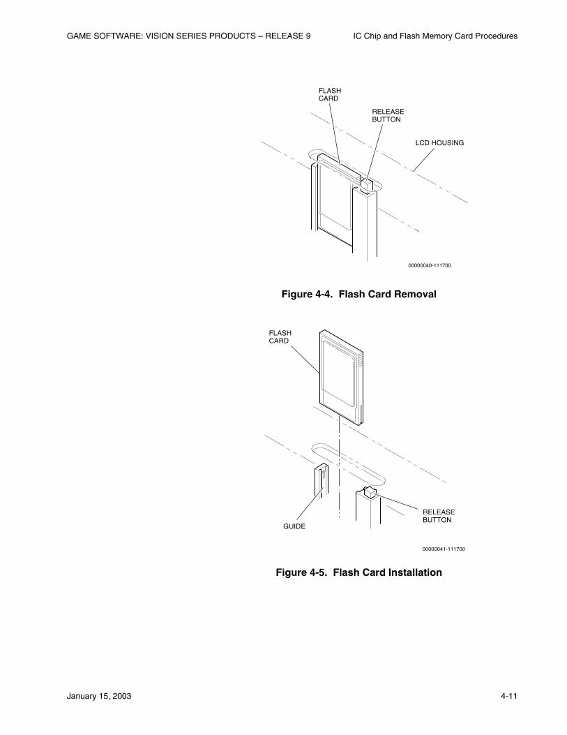
GAME SOFTWARE: VISION SERIES PRODUCTS – RELEASE 9 IC Chip and Flash Memory Card Procedures
January 15, 2003 4-11
Figure 4-4. Flash Card Removal
Figure 4-5. Flash Card Installation
00000040-111700
LCD HOUSING
FLASHCARD
RELEASEBUTTON
00000041-111700
GUIDE
FLASHCARD
RELEASEBUTTON

IC Chip and Flash Memory Card Procedures GAME SOFTWARE: VISION SERIES PRODUCTS – RELEASE 9
4-12 January 15, 2003
Installation
1. See Figure 4-5 and carefully insert the flash card into the socket until resistance is felt.
Note: The flash card will only go into the socket in the correct orientation. If it slides in and stops short of full insertion, pull the flash card out, turn it around and reinsert into the socket.
2. Carefully push the flash card fully into position. The release button will return to its out position and the flash card will be flush with the LCD housing (see Figure 4-4).
3. Turn the machine power on. Refer to Section 2 for information about selecting programmable attract mode options. Refer to the Troubleshooting: Game Machines manual to resolve any error messages that may appear on the displays.
4. Close and lock the machine door.
4.5.2 Setups (LCD Options)
The LCD stores these settings in its flash memory. For more information on available settings, refer to the program summary report (PSR) for the ATA version installed.
4.5.3 Flash Card Programming with Vision Builder Software
Custom graphic and audio displays are loaded onto flash cards using the Vision Builder program that runs on the Windows® 95 operating system.
Contact IGT Firmware Engineering for details on this program. PC hardware is necessary for operation.
GAME SOFTWARE: VISION SERIES PRODUCTS – RELEASE 9 IC Chip and Flash Memory Card Procedures
January 15, 2003 4-13
4.6 Game Program Change
Use the following procedure to replace game programs in Vision Series machines equipped with an LCD.
Note: Game program changes are highly regulated in certain gaming jurisdictions. Some jurisdictions require the presence of a gaming agent during this procedure. Verify state and local legal requirements before changing programs.
Newer flash memory cards may require more memory in the LCD. Ensure that the LCD has sufficient memory before changing programs.
1. Turn the machine power off.
2. Remnove the processor board from the machine, and remove the game, stepper base and version PROMs from the processor board (refer to Section 4.1.1).
3. Remove the Bonus Game Module (BGM) from the LCD (refer to Section 4.5).
4. Install the new game, stepper base and version PROMs on the processor board and return the board to the machine (refer to Section 4.1.1).
5. Install the new sound SIMM board if the machine has stereo sound (refer to Section 4.2).
6. Install the new BGM in the top slot of the LCD and install the RFA card in the slot on the left side of the LCD (Refer to Section 4.5).
7. Turn the machine power on. The LCD indicates the status of the game replacement.
8. When the LCD displays the “Enter new time” prompt, turn the machine power off.
9. Remove the RFA card and turn the machine power on. When the VFD indicates that the machine is experiencing a RAM error, turn the Attendant key.
10. When prompted by the message on the VFD, press the operator switch on the processor board, hold for two to three seconds, then release. The game program change is complete when the LCD and VFD display game play messages.

January 15, 2003 5-1
Section 5Game Software Testing
Use the following procedure when the machine is in the idle mode to verify that the game program software is operating correctly.
1. Turn the machine power off. Open the machine door, unlock and remove the processor board. Verify that the program numbers on the game ICs are compatible with the machine hardware options and that they are installed correctly.
2. Replace the processor board. Power up the machine and use the Diagnostic option on the Operator or Attendant menu to check inputs, outputs, and set options.
Note: If the software does not seem to drive a particular hardware component, contact an IGT agent to verify software capabilities.
3. Play enough games to verify correct operation of the games and player panel switches.
4. Use the Accounting Menu to verify that software data is being metered and the desired options are selected.
5. Close and lock all doors.