Embed Size (px)
Citation preview

Section 07 Entity Relationship Diagrams 1
07 Entity Relationship Diagrams (ERD)A Data Modelling Case Tool
HSQ - DATABASES & SQL
And Franchise Colleges
By MANSHA NAWAZ
Section 07 Entity Relationship Diagrams 2
• System Data Model is perceived in terms of a Entity Relationship Diagram (ERD).
• The ERD can be translated into Conventional DBMS Table Structures
• Hierarchical (IMS)
• Codasyl
• Relational (MS SQL Server or MS Access)
• ERD consists of
– ENTITIES
– ATTRIBUTES
– RELATIONSHIPS (Degree & Dependency)
• Start by identifying the entities and their attributes• Identify associations/relationships between entities• Draw up an ER Diagram (ERD) using appropriate notation• Applying rules, translate ERD into a set of well-normalised tables
Entity-Relationship Diagrams (ERD).
Section 07 Entity Relationship Diagrams 3
ERD Notations
• Many notations are used for Entity-Relationship Modelling.
• The one we use (the Howe notation) is particularly good for beginners.
• Seeing examples of more than one notation is useful as so many exist.
• The concepts are the same whatever the notation.
The creative bit is the identification of appropriate Entities, attributes and their relationships
The rest is learning how to adhere to and apply appropriate rules of ER Modelling correctly
Library of Free Data Models
Section 07 Entity Relationship Diagrams 4
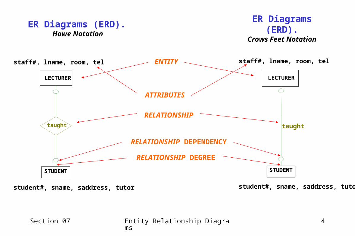
ER Diagrams (ERD). Howe Notation
STUDENT
LECTURER
taught
student#, sname, saddress, tutor
staff#, lname, room, tel
STUDENT
LECTURER
taught
student#, sname, saddress, tutor
staff#, lname, room, telENTITY
RELATIONSHIP
RELATIONSHIP DEGREE
ATTRIBUTES
RELATIONSHIP DEPENDENCY
ER Diagrams (ERD).Crows Feet Notation

Section 07 Entity Relationship Diagrams 5
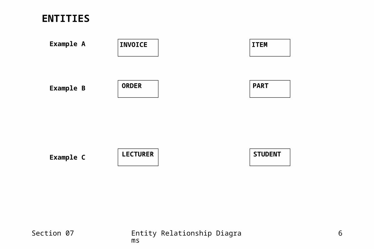
Identifying ENTITIESEntity is an object being modelled
– Table type of related data.– One Row Per Entity Occurrence.– independent existence– uniquely identifiable by their properties– something you need to keep a list of!– Nouns / thing / object– eg employee, order, machine, property– Look for object name or thing.– eg INVOICE, ORDER, STUDENT, LECTURER– Look for things requiring a list of associated
records or tabular list of data.– Each existence of an entity value requires a
record. – Look for things with record keys.– eg stock code -> STOCK reg. no. -> CAR
NOUNENTITIES
• If the scenario you are working with is in the form of narrative it is likely that most of the entities of interest will appear in the narrative as nouns (words used as labels for things) e.g. Customer, Delivery Note, Bill of Materials, Prescription, Drug, Payment etc…
• In a real systems analysis and design the entities will be derived from the DFD
• They can be also appear as paperwork, physical items, software components, and similar.
• Sometimes they are a little more abstract and masquerade as processes e.g. assignment, delivery, load, journey…..
Section 07 Entity Relationship Diagrams 6
INVOICE ITEM
ORDER PART
LECTURER STUDENT
Example A
Example B
Example C
ENTITIES
Section 07 Entity Relationship Diagrams 7
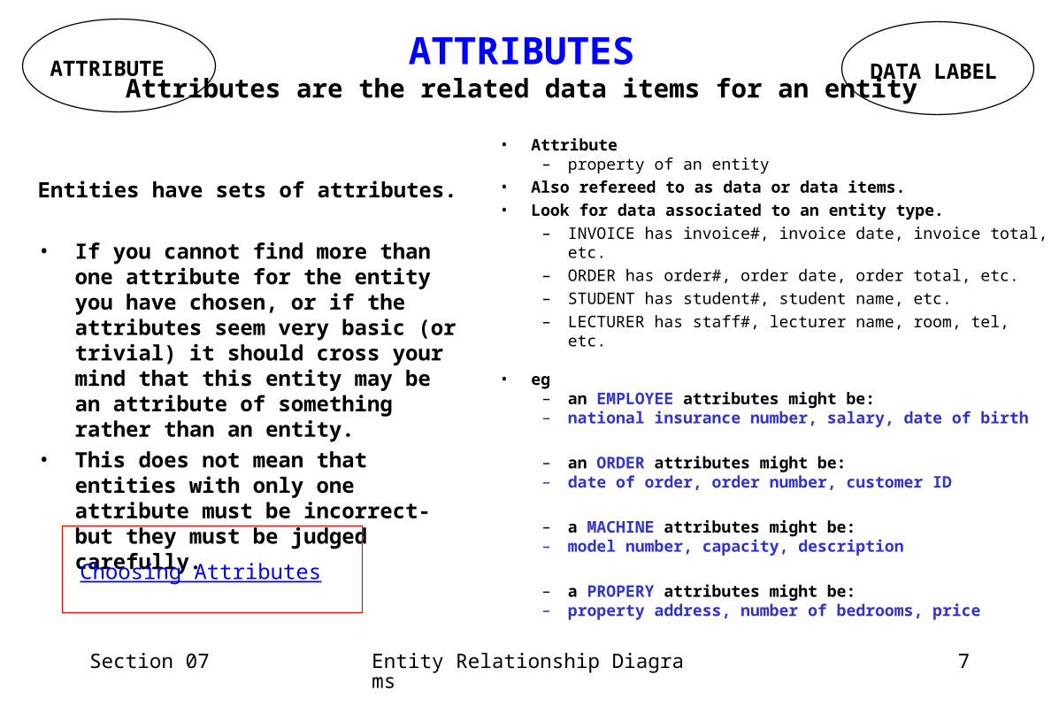
• Attribute– property of an entity
• Also refereed to as data or data items.• Look for data associated to an entity type.
– INVOICE has invoice#, invoice date, invoice total, etc.– ORDER has order#, order date, order total, etc.– STUDENT has student#, student name, etc.– LECTURER has staff#, lecturer name, room, tel, etc.
• eg– an EMPLOYEE attributes might be: – national insurance number, salary, date of birth
– an ORDER attributes might be: – date of order, order number, customer ID
– a MACHINE attributes might be: – model number, capacity, description
– a PROPERY attributes might be: – property address, number of bedrooms, price
ATTRIBUTE DATA LABELATTRIBUTES
Attributes are the related data items for an entity
Entities have sets of attributes.
• If you cannot find more than one attribute for the entity you have chosen, or if the attributes seem very basic (or trivial) it should cross your mind that this entity may be an attribute of something rather than an entity.
• This does not mean that entities with only one attribute must be incorrect- but they must be judged carefully.
Choosing Attributes

Section 07 Entity Relationship Diagrams 8
INVOICE ITEM
ORDER PART
LECTURER STUDENT
Example A
Example B
Example C
ATTRIBUTES
invoice#, invoice date, invoice totalinvoice#, invoice date, invoice total
order#, order date, order totalorder#, order date, order total
student#, student name, etc.student#, student name, etc.staff#, lecturer name, room, tel, etc.staff#, lecturer name, room, tel, etc.
item#, item name, item descitem#, item name, item desc
part#, part name, part descpart#, part name, part desc
Section 07 Entity Relationship Diagrams 9
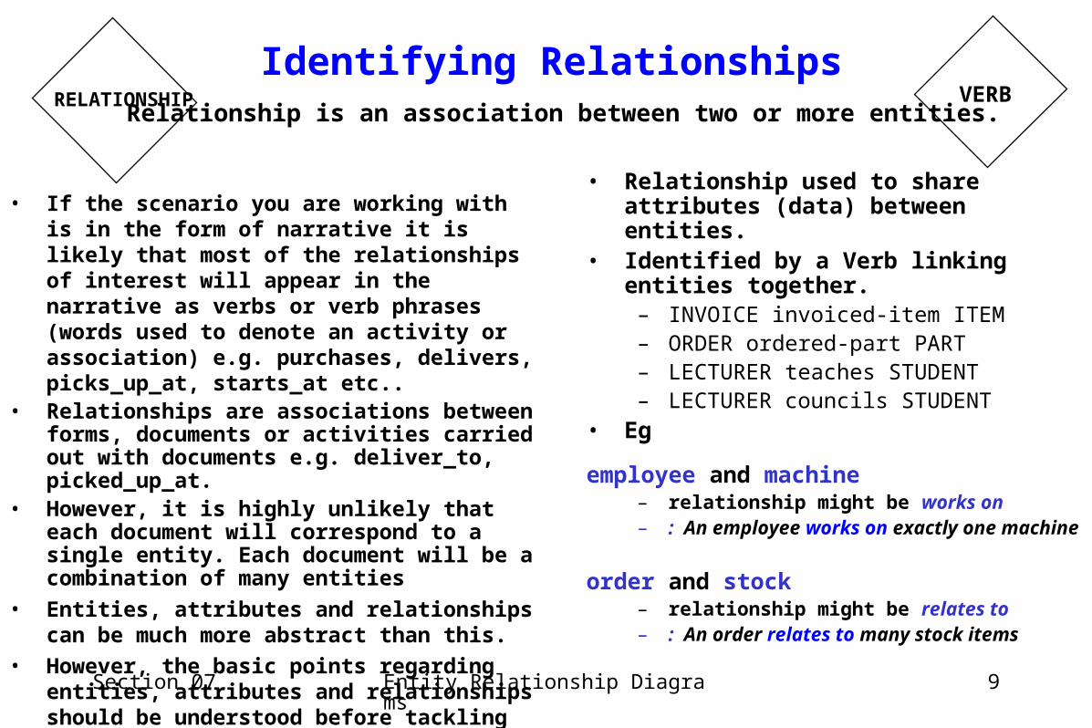
• Relationship used to share attributes (data) between entities.
• Identified by a Verb linking entities together.
– INVOICE invoiced-item ITEM– ORDER ordered-part PART– LECTURER teaches STUDENT– LECTURER councils STUDENT
• Eg
employee and machine– relationship might be works on – : An employee works on exactly one
machine
order and stock– relationship might be relates to – : An order relates to many stock items
VERBRELATIONSHIP
Identifying Relationships Relationship is an association between two or more entities.
• If the scenario you are working with is in the form of narrative it is likely that most of the relationships of interest will appear in the narrative as verbs or verb phrases (words used to denote an activity or association) e.g. purchases, delivers, picks_up_at, starts_at etc..
• Relationships are associations between forms, documents or activities carried out with documents e.g. deliver_to, picked_up_at.
• However, it is highly unlikely that each document will correspond to a single entity. Each document will be a combination of many entities
• Entities, attributes and relationships can be much more abstract than this.
• However, the basic points regarding entities, attributes and relationships should be understood before tackling more abstract data objects.
Section 07 Entity Relationship Diagrams 10
INVOICE invoiceditem
ITEM
ORDER PARTorderedpart
LECTURER STUDENT
teaches
council
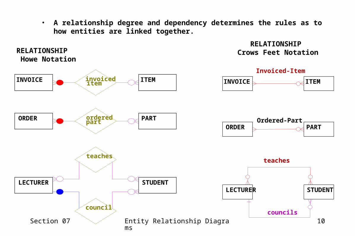
• A relationship degree and dependency determines the rules as to how entities are linked together.
RELATIONSHIP Howe Notation
Invoiced-Item
INVOICE ITEM
ORDER PART
LECTURER STUDENT
Ordered-Part
teaches
councils
RELATIONSHIP Crows Feet Notation

Section 07 Entity Relationship Diagrams 11
RELATIONSHIP DEGREE.
• These provide use the means to build the DATA MODEL
• Used to indicate how entities are linked
• The relationship allows use to share data via the link.
• Used by the DBMS to link across tables for multiple views.
• Three possible degrees
– 1:1 one to one
– 1:m one to many
– m:n many to many
• Each represent a unique view to sharing data across entities. 1 1
1 m
m
n

Section 07 Entity Relationship Diagrams 12
1:1 Relationship (one to one)
“An employee works on at most one machine”
“A machine is worked on by at most one employee”
• Enterprise Rules Represented:
Employee “Works on” Machine• E1 M1• E2 M2• E3 M3• E4 M4• E5
Entity Relationship Occurrence Diagram 1:1
Employee MachineWorks on11
Section 07 Entity Relationship Diagrams 13
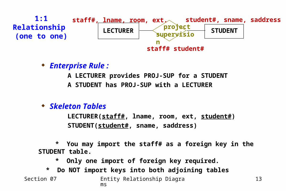
staff#, lname, room, ext. student#, sname, saddress
staff# student#
LECTURER STUDENT projectsupervision
1:1 Relationship (one to one)
Enterprise Rule :A LECTURER provides PROJ-SUP for a STUDENT
A STUDENT has PROJ-SUP with a LECTURER
Skeleton Tables LECTURER(staff#, lname, room, ext, student#)
STUDENT(student#, sname, saddress)
* You may import the staff# as a foreign key in the STUDENT table.
* Only one import of foreign key required.
* Do NOT import keys into both adjoining tables
Section 07 Entity Relationship Diagrams 14
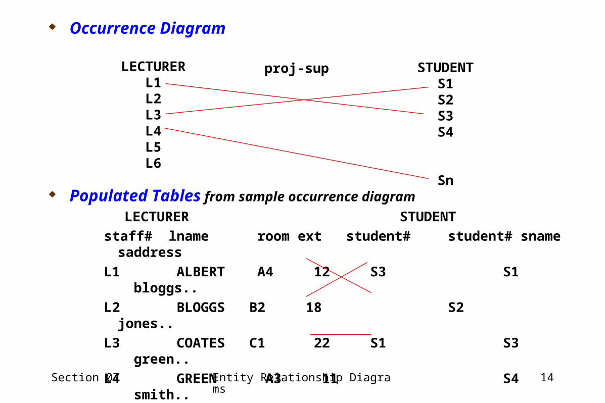
Populated Tables from sample occurrence diagram
LECTURER STUDENT
staff# lname room ext student# student# sname saddress
L1 ALBERT A4 12 S3 S1 bloggs..
L2 BLOGGS B2 18 S2 jones..
L3 COATES C1 22 S1 S3 green..
L4 GREEN A3 11 S4 smith..
L5 JONES D1 53 Sn Sn zues..
L6 SMITH A5 18
LECTURERL1L2L3L4L5L6
proj-sup STUDENTS1S2S3S4
Sn
Occurrence Diagram

Section 07 Entity Relationship Diagrams 15
1:M Relationship (one to many)
name relationships from M to 1
Employee MachineWorks on M1
“An employee may work on one or many machines”
“A machine is worked on by at most one employee”
• Enterprise Rules Represented:
Entity Relationship Occurrence Diagram 1:M
Employee “Works on” Machine• E1 M1• E2 M2• E3 M3• E4 M4• E5
• What would a M:1 look like?
Section 07 Entity Relationship Diagrams 16
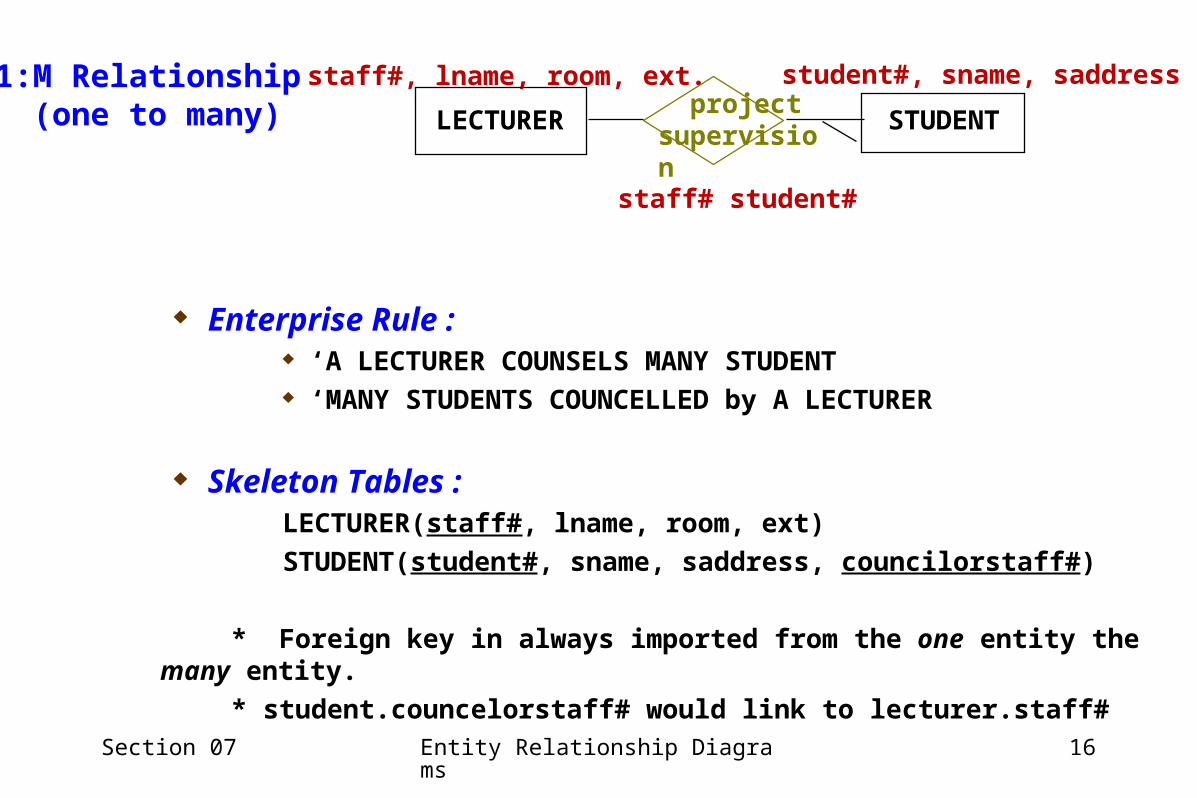
staff#, lname, room, ext. student#, sname, saddress
staff# student#
LECTURER STUDENT projectsupervision
1:M Relationship (one to many)
Enterprise Rule : ‘A LECTURER COUNSELS MANY STUDENT ‘MANY STUDENTS COUNCELLED by A LECTURER
Skeleton Tables :LECTURER(staff#, lname, room, ext)
STUDENT(student#, sname, saddress, councilorstaff#)
* Foreign key in always imported from the one entity the many entity.
* student.councelorstaff# would link to lecturer.staff#
Section 07 Entity Relationship Diagrams 17
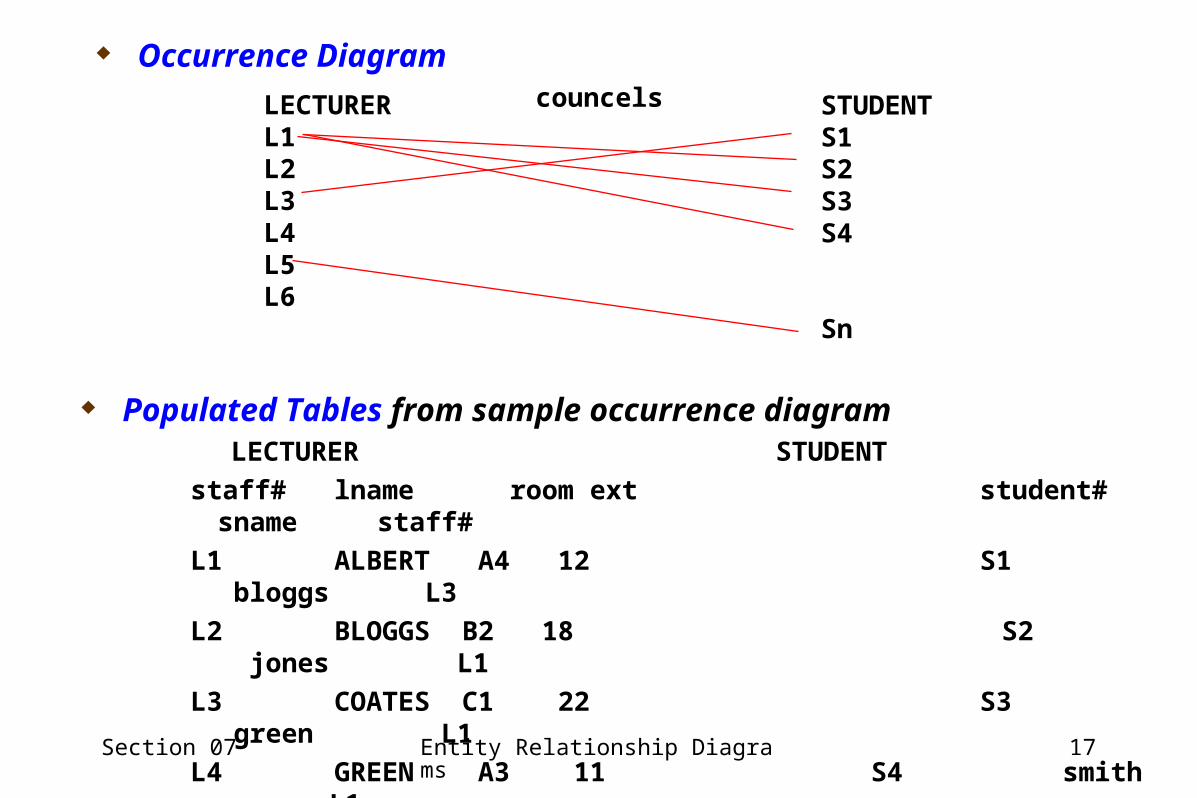
Populated Tables from sample occurrence diagramLECTURER STUDENT
staff# lname room ext student# sname staff#
L1 ALBERT A4 12 S1 bloggs L3
L2 BLOGGS B2 18 S2 jones L1
L3 COATES C1 22 S3 green L1
L4 GREEN A3 11 S4 smith L1
L5 JONES D1 53 Sn zues L5
L6 SMITH A5 18
LECTURERL1L2L3L4L5L6
councels STUDENTS1S2S3S4
Sn
Occurrence Diagram

Section 07 Entity Relationship Diagrams 18
M:N Relationship (many to many)
M:M
Employee MachineWorks on NM
Enterprise Rules Represented:
“An employee may work on one or many machines”
“A machine is worked on by one or many employees”
Entity Relationship Occurrence Diagram M:M Employee “Works on” Machine• E1 M1• E2 M2• E3 M3• E4 M4• E5

Section 07 Entity Relationship Diagrams 19
LECTURER
L1L2L3L4L5L6
lectures STUDENT
S1S2S3S4
Sn
– Enterprise Rule :• ‘MANY LECTURERS LECTURES MANY STUDENTS• ‘MANY STUDENTS LECTURED by MANY LECTURER
– Occurrence Diagram :
• m:n MANY-to-MANY Relationship
staff#, lname, room, ext. student#, sname, saddress
staff# student#
LECTURER STUDENT projectsupervision

Section 07 Entity Relationship Diagrams 20
Skeleton Tables : m:n relationships cannot be represented by foreign key import
A relationship table (link table) resolves the problem
m:n becomes 1 to m and m to 1 RELATIONSHIPS
Why we cannot populated tables using foreign key import using links from occurrence diagram & sample data to show relationship)
LECTURER STUDENT
staff# lname room ext student# student# sname staff
L1 ALBERT A4 12 S1, S2, S3, S4 S1 bloggs L1, L2, L3, L4
L2 BLOGGS B2 18 S1 S2 jones L1
L3 COATES C1 22 S1 S3 green L1
L4 GREEN A3 11 S1 S4 smith L1
L5 JONES D1 53 Sn Sn zues L5
L6 SMITH A5 18
VARIABLE LENGTH RECORDS ARE GENERATED!!!
SOLUTION SECTION 06 – MANY TO MANY DECOMPOSITION
Section 07 Entity Relationship Diagrams 21
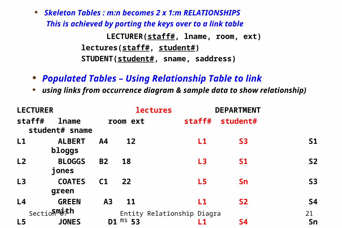
Skeleton Tables : m:n becomes 2 x 1:m RELATIONSHIPS
This is achieved by porting the keys over to a link table
LECTURER(staff#, lname, room, ext)
lectures(staff#, student#)
STUDENT(student#, sname, saddress)
Populated Tables – Using Relationship Table to link using links from occurrence diagram & sample data to show relationship)
LECTURER lectures DEPARTMENT
staff# lname room ext staff# student# student# sname
L1 ALBERT A4 12 L1 S3 S1 bloggs
L2 BLOGGS B2 18 L3 S1 S2 jones
L3 COATES C1 22 L5 Sn S3 green
L4 GREEN A3 11 L1 S2 S4 smith
L5 JONES D1 53 L1 S4 Sn zues
L6 SMITH A5 18 L1 S1
L2 S1
L3 S1
Section 07 Entity Relationship Diagrams 22
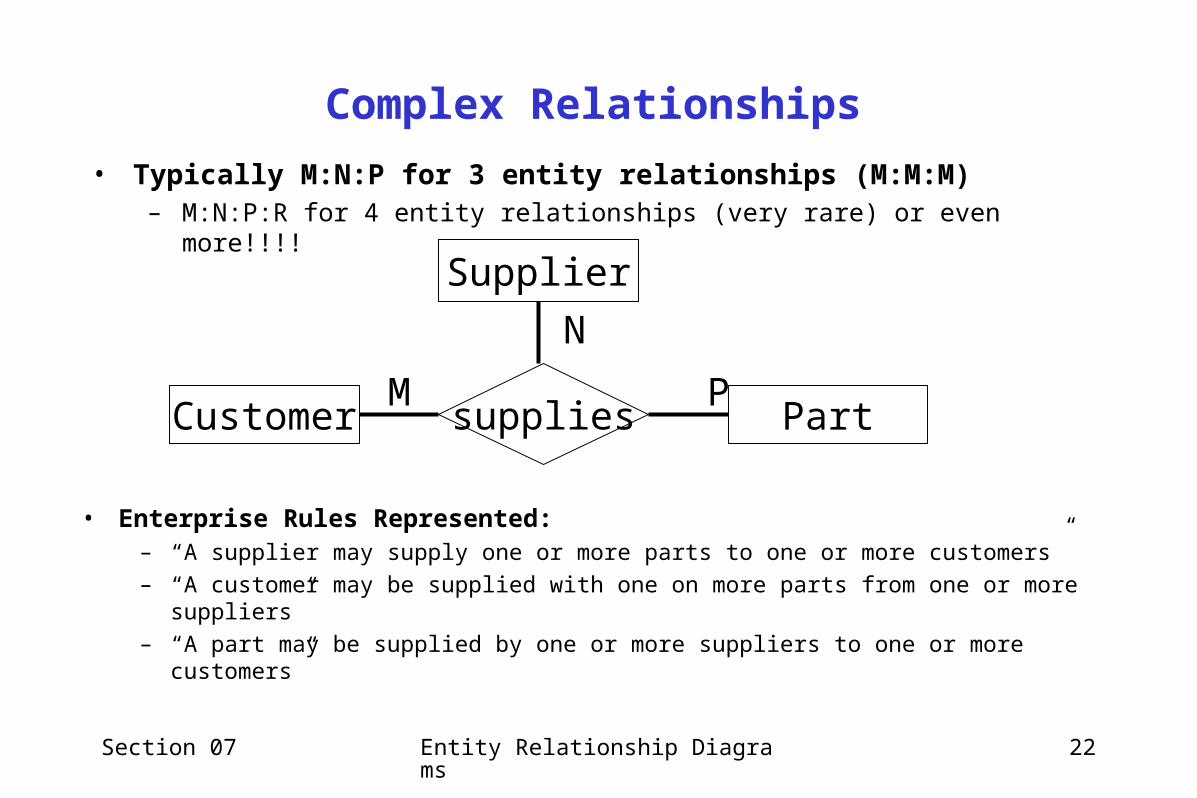
Complex Relationships
• Typically M:N:P for 3 entity relationships (M:M:M)– M:N:P:R for 4 entity relationships (very rare) or even more!!!!
Customer PartsuppliesPM
Supplier
N
• Enterprise Rules Represented:– “A supplier may supply one or more parts to one or more customers”– “A customer may be supplied with one on more parts from one or more suppliers”– “A part may be supplied by one or more suppliers to one or more customers”
Section 07 Entity Relationship Diagrams 23
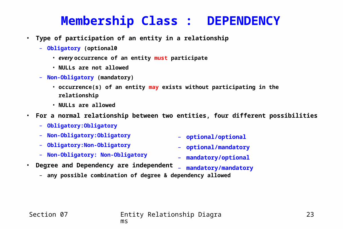
Membership Class : DEPENDENCY• Type of participation of an entity in a relationship
– Obligatory (optional0
• every occurrence of an entity must participate
• NULLs are not allowed
– Non-Obligatory (mandatory)
• occurrence(s) of an entity may exists without participating in the relationship
• NULLs are allowed
• For a normal relationship between two entities, four different possibilities
– Obligatory:Obligatory
– Non-Obligatory:Obligatory
– Obligatory:Non-Obligatory
– Non-Obligatory: Non-Obligatory
• Degree and Dependency are independent
– any possible combination of degree & dependency allowed
– optional/optional
– optional/mandatory
– mandatory/optional
– mandatory/mandatory
Section 07 Entity Relationship Diagrams 24
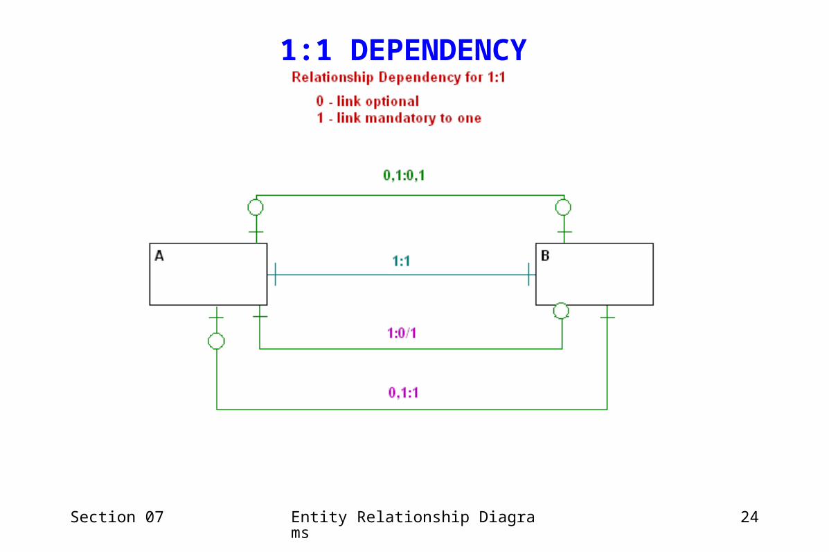
1:1 DEPENDENCY
Section 07 Entity Relationship Diagrams 25
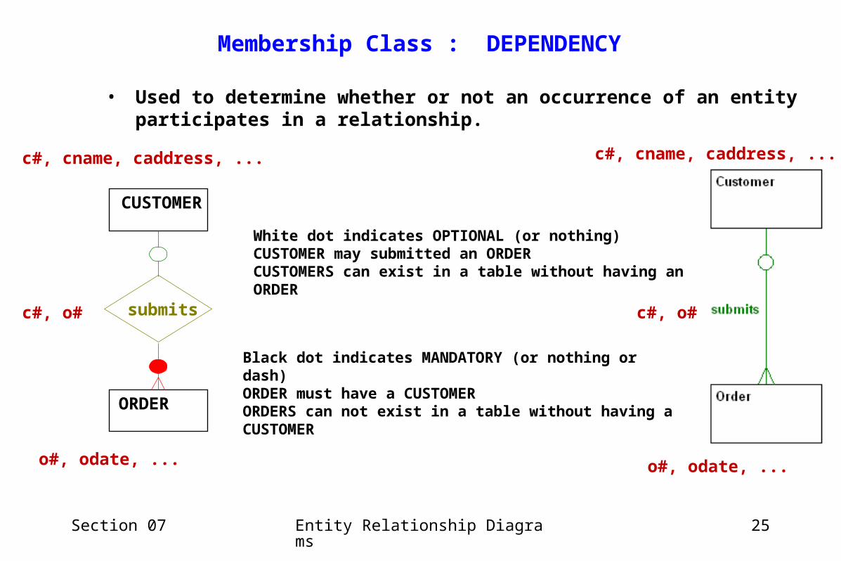
• Used to determine whether or not an occurrence of an entity participates in a relationship.
c#, cname, caddress, ...
o#, odate, ...
c#, o# submits
CUSTOMER
ORDER
White dot indicates OPTIONAL (or nothing)CUSTOMER may submitted an ORDERCUSTOMERS can exist in a table without having an ORDER
Black dot indicates MANDATORY (or nothing or dash)ORDER must have a CUSTOMERORDERS can not exist in a table without having a CUSTOMER
Membership Class : DEPENDENCY
c#, cname, caddress, ...
c#, o#
o#, odate, ...

Section 07 Entity Relationship Diagrams 26
If we force record linkage between an entity the relationship is mandatory.
mandatory (dependent or obligatory)» 1 : 1 contains a 1:1» 1 : M contains a 1:1, 1:M» M : N contains a 1:1, 1:M, M:1, M:N
If we allow records to exist without linkage to other entities the relationship is optional.
optional (non-dependent or non-obligatory)» 1 : 1 can be mapped as 0,1:0,1» 1 : M can be mapped as 0,1:0,1,M» M : N can be mapped as 0,1,M : 0,1,N
Section 07 Entity Relationship Diagrams 27
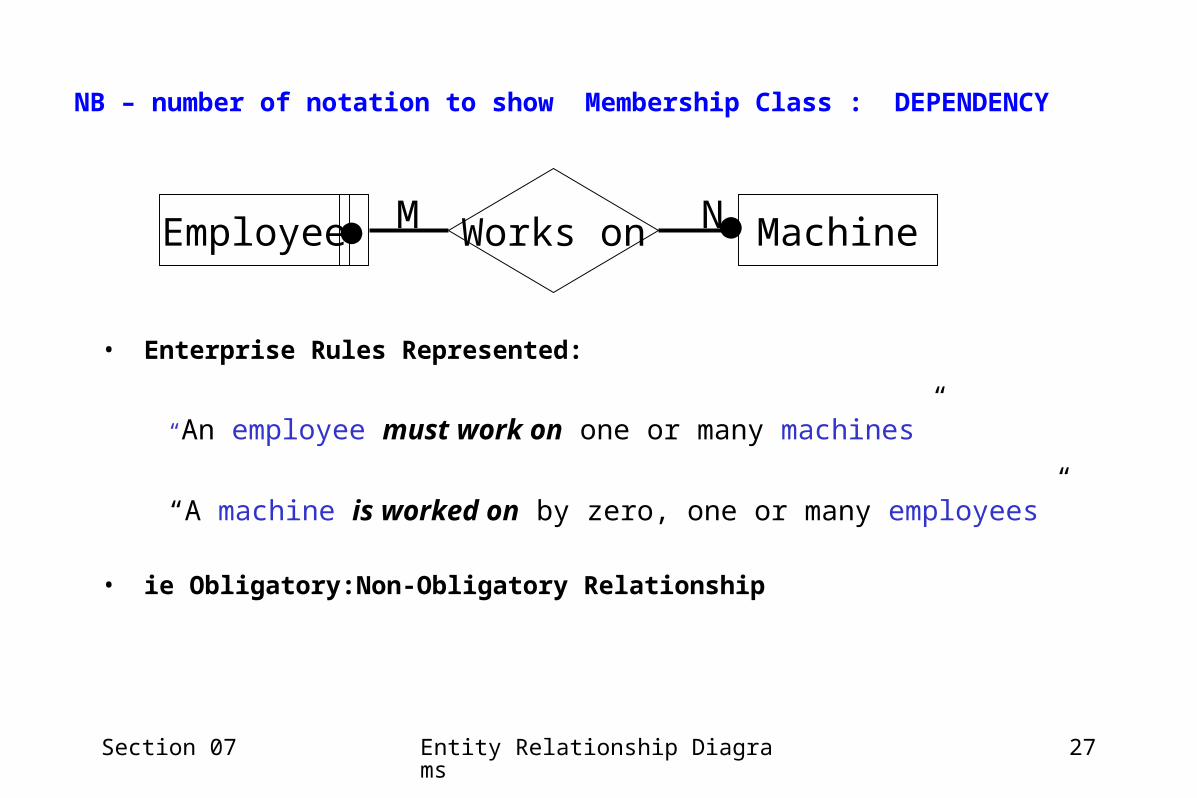
NB – number of notation to show Membership Class : DEPENDENCY
• Enterprise Rules Represented:
“An employee must work on one or many machines”
“A machine is worked on by zero, one or many employees”
• ie Obligatory:Non-Obligatory Relationship
Employee MachineWorks on NM
Section 07 Entity Relationship Diagrams 28
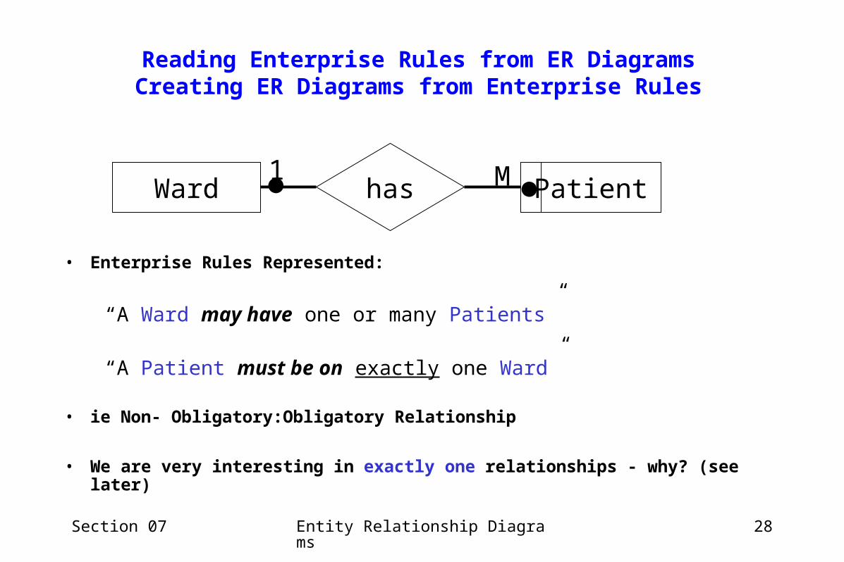
Reading Enterprise Rules from ER DiagramsCreating ER Diagrams from Enterprise Rules
Ward Patienthas M1 • Enterprise Rules Represented:
“A Ward may have one or many Patients”
“A Patient must be on exactly one Ward”
• ie Non- Obligatory:Obligatory Relationship
• We are very interesting in exactly one relationships - why? (see later)
Section 07 Entity Relationship Diagrams 29
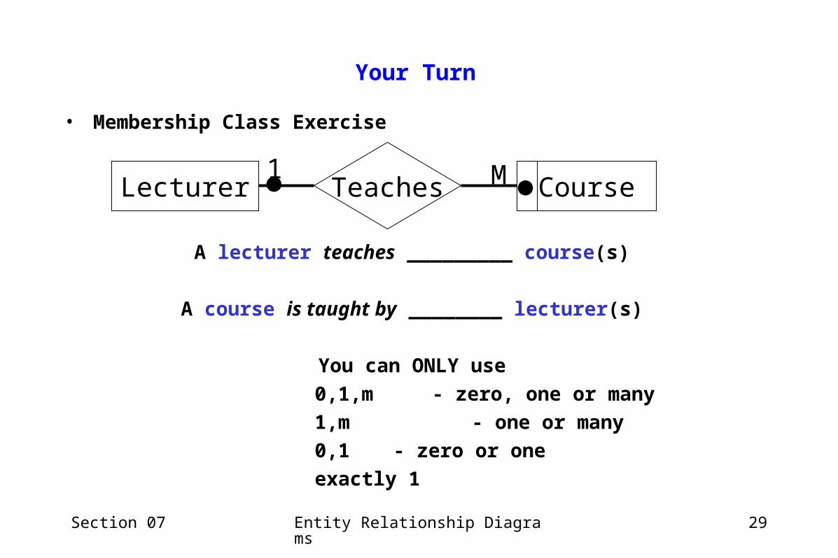
Your Turn
• Membership Class Exercise
Lecturer CourseTeaches M1 A lecturer teaches _________ course(s)
A course is taught by ________ lecturer(s)
You can ONLY use
0,1,m - zero, one or many
1,m - one or many
0,1 - zero or one
exactly 1

Section 07 Entity Relationship Diagrams 30
The solution ...
Reading (looking) from the Lecturer end:
A lecturer teaches 0,1,m course(s)
Reading (looking) from the Course end:
A course is taught by exactly 1 lecturer(s)
Lecturer CourseTeaches M1
Section 07 Entity Relationship Diagrams 31
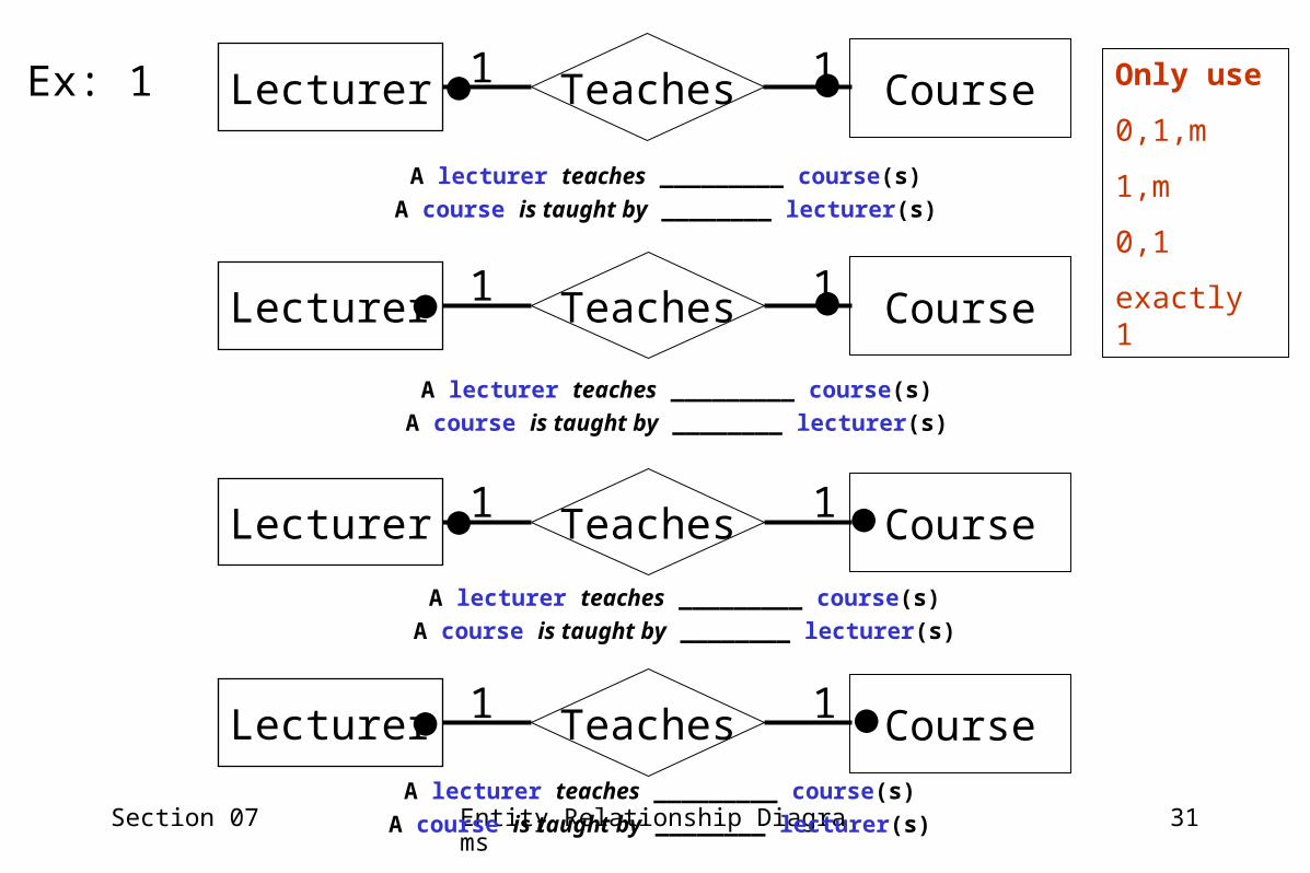
A lecturer teaches _________ course(s)
A course is taught by ________ lecturer(s)
Lecturer CourseTeaches1 1
Lecturer CourseTeaches1 1
Lecturer CourseTeaches1 1
A lecturer teaches _________ course(s)
A course is taught by ________ lecturer(s)
A lecturer teaches _________ course(s)
A course is taught by ________ lecturer(s)
A lecturer teaches _________ course(s)
A course is taught by ________ lecturer(s)
Lecturer CourseTeaches1 1
Only use
0,1,m
1,m
0,1
exactly 1
Ex: 1
Section 07 Entity Relationship Diagrams 32
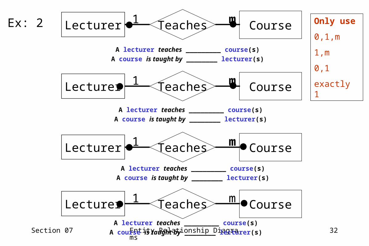
A lecturer teaches _________ course(s)
A course is taught by ________ lecturer(s)
Lecturer CourseTeaches1 m
Lecturer CourseTeaches1 m
Lecturer CourseTeaches1 m
A lecturer teaches _________ course(s)
A course is taught by ________ lecturer(s)
A lecturer teaches _________ course(s)
A course is taught by ________ lecturer(s)
A lecturer teaches _________ course(s)
A course is taught by ________ lecturer(s)
Lecturer CourseTeaches1 m
Only use
0,1,m
1,m
0,1
exactly 1
Ex: 2

Section 07 Entity Relationship Diagrams 33
A lecturer teaches _________ course(s)
A course is taught by ________ lecturer(s)
Lecturer CourseTeachesm 1
Lecturer CourseTeachesm 1
Lecturer CourseTeachesm 1
A lecturer teaches _________ course(s)
A course is taught by ________ lecturer(s)
A lecturer teaches _________ course(s)
A course is taught by ________ lecturer(s)
A lecturer teaches _________ course(s)
A course is taught by ________ lecturer(s)
Lecturer CourseTeachesm 1
Only use
0,1,m
1,m
0,1
exactly 1
Ex: 3

Section 07 Entity Relationship Diagrams 34
A lecturer teaches _________ course(s)
A course is taught by ________ lecturer(s)
Lecturer CourseTeachesm m
Lecturer CourseTeachesm m
Lecturer CourseTeachesm m
A lecturer teaches _________ course(s)
A course is taught by ________ lecturer(s)
A lecturer teaches _________ course(s)
A course is taught by ________ lecturer(s)
A lecturer teaches _________ course(s)
A course is taught by ________ lecturer(s)
Lecturer CourseTeachesm m
Only use
0,1,m
1,m
0,1
exactly 1
Ex: 4
Section 07 Entity Relationship Diagrams 35
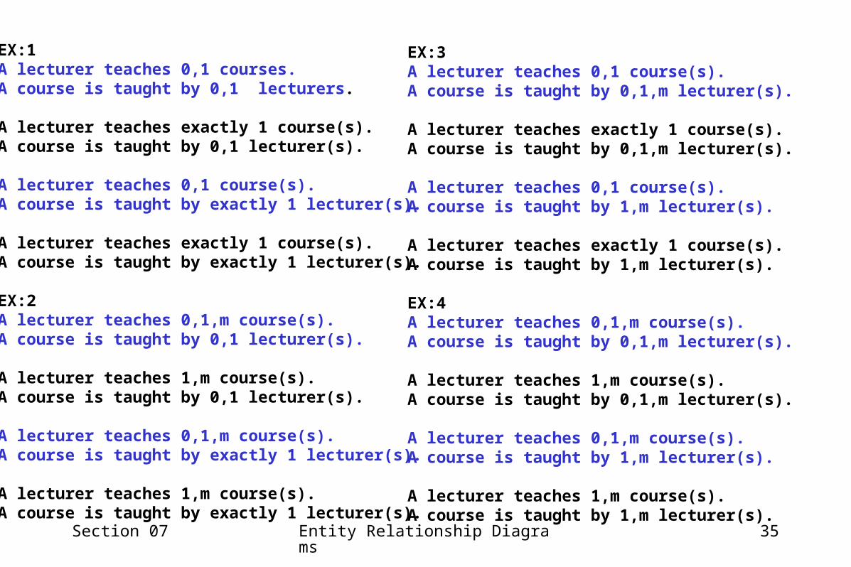
EX:1A lecturer teaches 0,1 courses.A course is taught by 0,1 lecturers.
A lecturer teaches exactly 1 course(s).A course is taught by 0,1 lecturer(s).
A lecturer teaches 0,1 course(s).A course is taught by exactly 1 lecturer(s).
A lecturer teaches exactly 1 course(s).A course is taught by exactly 1 lecturer(s).
EX:2A lecturer teaches 0,1,m course(s).A course is taught by 0,1 lecturer(s).
A lecturer teaches 1,m course(s).A course is taught by 0,1 lecturer(s).
A lecturer teaches 0,1,m course(s).A course is taught by exactly 1 lecturer(s).
A lecturer teaches 1,m course(s).A course is taught by exactly 1 lecturer(s).
EX:3A lecturer teaches 0,1 course(s).A course is taught by 0,1,m lecturer(s).
A lecturer teaches exactly 1 course(s).A course is taught by 0,1,m lecturer(s).
A lecturer teaches 0,1 course(s).A course is taught by 1,m lecturer(s).
A lecturer teaches exactly 1 course(s).A course is taught by 1,m lecturer(s).
EX:4A lecturer teaches 0,1,m course(s).A course is taught by 0,1,m lecturer(s).
A lecturer teaches 1,m course(s).A course is taught by 0,1,m lecturer(s).
A lecturer teaches 0,1,m course(s).A course is taught by 1,m lecturer(s).
A lecturer teaches 1,m course(s).A course is taught by 1,m lecturer(s).
Section 07 Entity Relationship Diagrams 36
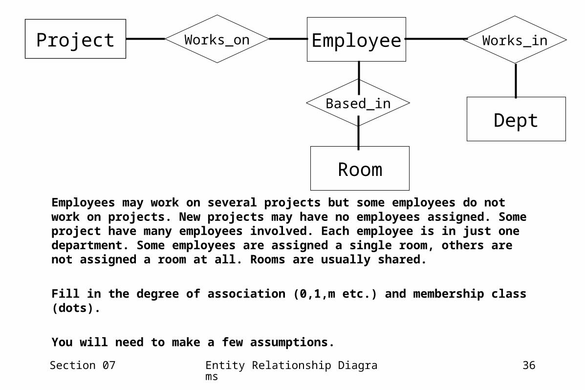
Project Works_on Works_in
Based_inDept
Room
Employees may work on several projects but some employees do not work on projects. New projects may have no employees assigned. Some project have many employees involved. Each employee is in just one department. Some employees are assigned a single room, others are not assigned a room at all. Rooms are usually shared.
Fill in the degree of association (0,1,m etc.) and membership class (dots).
You will need to make a few assumptions.
Employee
Section 07 Entity Relationship Diagrams 37
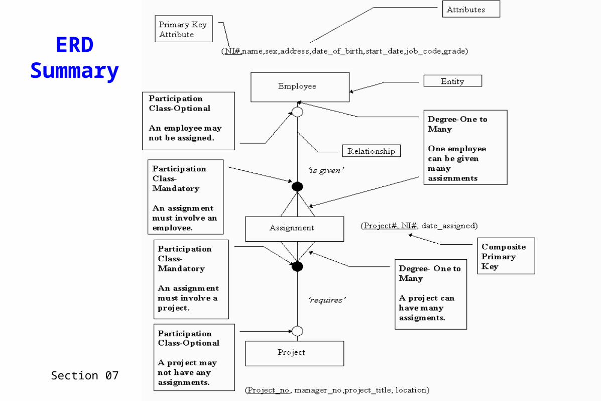
ERDSummary
Section 07 Entity Relationship Diagrams 38
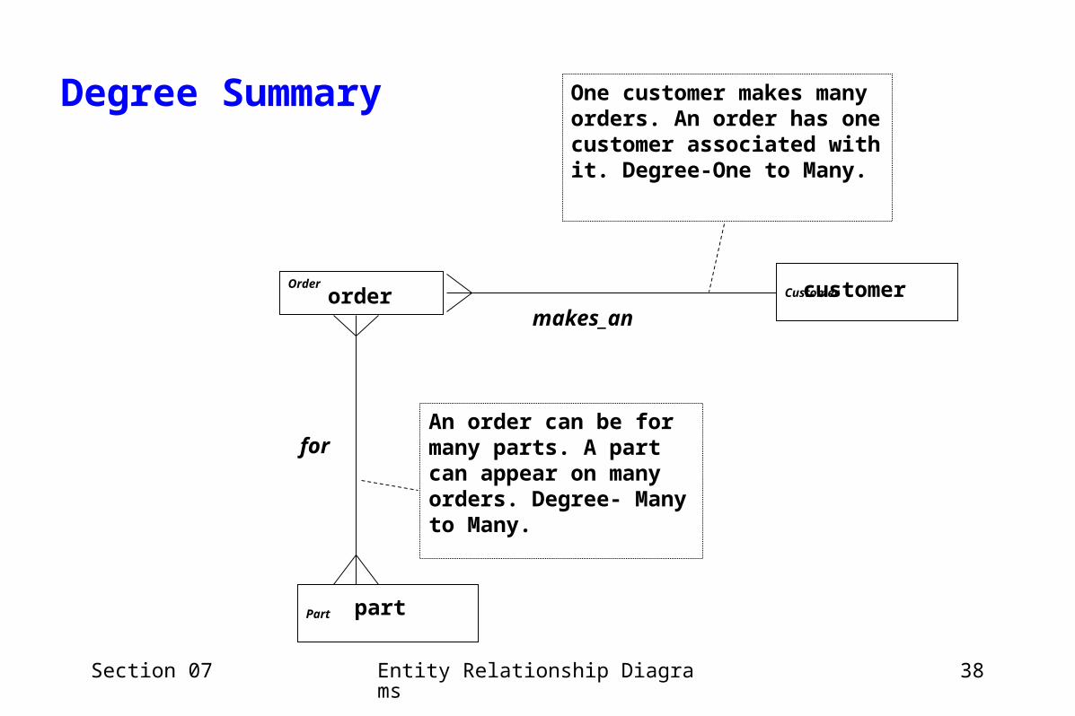
Degree Summary
makes_an
for
Customer
Part
Order
An order can be for many parts. A part can appear on many orders. Degree- Many to Many.
One customer makes many orders. An order has one customer associated with it. Degree-One to Many.
order customer
part
Section 07 Entity Relationship Diagrams 39
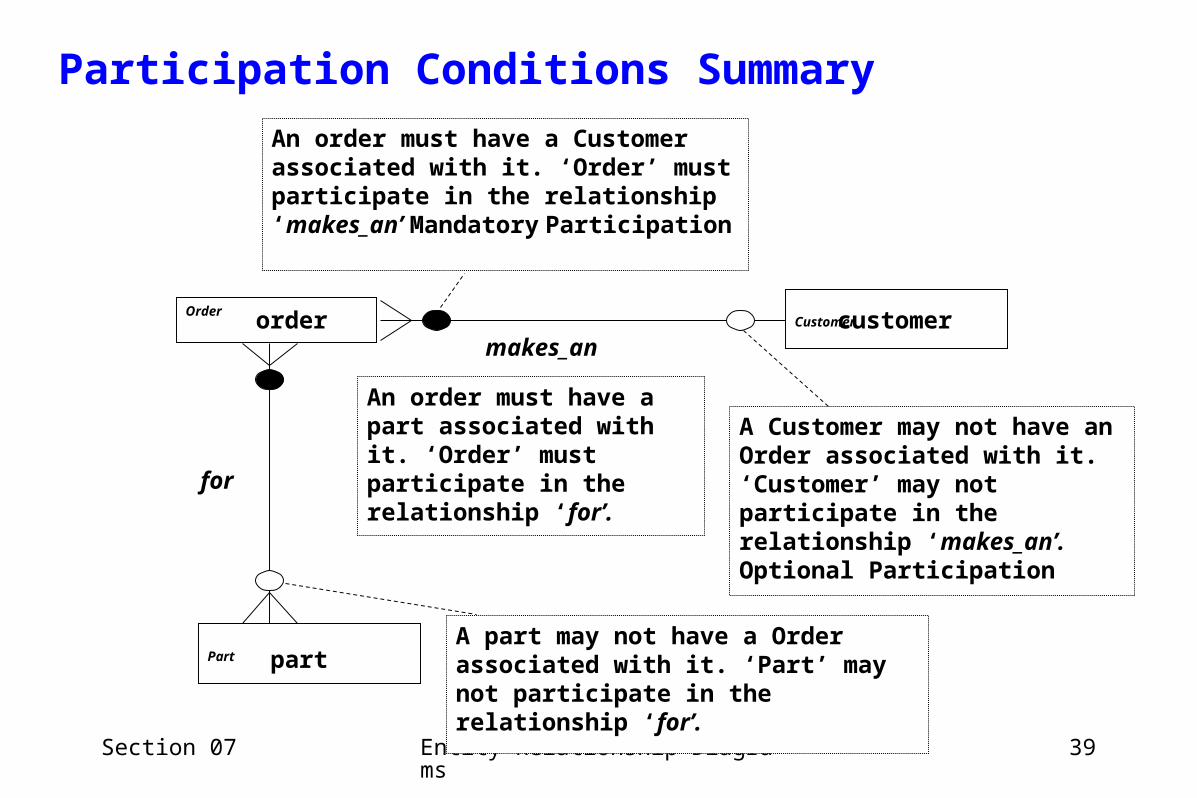
Participation Conditions Summary
A Customer may not have an Order associated with it. ‘Customer’ may not participate in the relationship ‘makes_an’. Optional Participation
makes_an
for
Customer
Part
Order
An order must have a part associated with it. ‘Order’ must participate in the relationship ‘for’.
An order must have a Customer associated with it. ‘Order’ must participate in the relationship ‘makes_an’ Mandatory Participation
A part may not have a Order associated with it. ‘Part’ may not participate in the relationship ‘for’.
order customer
part
Section 07 Entity Relationship Diagrams 40
Modelling Entity Relationship Diagrams• How to tell what to model
– an appropriate entity?– an appropriate attribute?– An appropriate relationship?
• Experience– practice makes better
• Reading hints in scenario– if scenario based - especially in ICA or test!
• Acting on information from fact finding investigations
• Never expect to get it right the first time in the real world – (or the second!)– E-R Modelling is an iterative process– It is a CREATIVE process
Section 07 Entity Relationship Diagrams 41
Reading the hints in the scenario or acting on information from fact finding investigations
• If the scenario you are working with is in the form of narrative it is likely that most of the entities of interest will appear in the narrative as nouns (words used as labels for things) e.g. Customer, Delivery Note, Bill of Materials, Prescription, Drug, Payment etc…
• In a real systems analysis entities appear as paperwork, physical items, software components, and similar.
• Sometimes they are a little more abstract and masquerade as processes e.g. assignment, delivery, load, journey…..
• Boundary of the problem– eg, client wants
• a computerised booking system only• a computerised video rental system
Section 07 Entity Relationship Diagrams 42
• Entities actually highlighted explicitly– “record details of bookings, properties and…”
• Attributes actually highlighted even if entities aren’t– “the secretary keeps a record of the order number, date of order and what items of stock are required together with their respective quantity”
• Nouns and verbs– sometimes provide a hint as to entities and their relationships
• can see them as Enterprise Rules• eg “a customer can make several orders, but an order relates to just one customer”
• Look for Enterprise Rules either at attribute level or at entity level• “a part description can be the same for several part numbers, although part numbers are unique”• “A part may be used in several machine repairs, and a machine repair my involve at least one part”
Section 07 Entity Relationship Diagrams 43
End of Lecture