Embed Size (px)
Citation preview

SECTION 03300-1 of 25 DIVISION 3 - CONCRETE CAST-IN-PLACE CONCRETE
Published: 01/01 Revised:
Delete Specification Section 03300 - CAST-IN-PLACE CONCRETE from the Anne Arundel County Standard specifications and replace with the following:
03300.01 GENERAL
A. Description
1. This section specifies the requirements for Portland Cement cast-in-place concrete.
2. Related Work Specified Elsewhere
a. Forms and Formwork; Section 03010.
b. Concrete Reinforcement; Section 03200.
c. Concrete Finishes; Section 03040.
B. Quality Assurance
1. Properties of Concrete
a. General Requirements
1) Design mixes to produce concrete of proper workability, durability, compressive strength, maximum density, and minimum shrinkage and permeability.
2) Design mixes to have a minimum water-cement ratio, the largest permissible maximum size specified coarse aggregate, and an optimum percentage of fine aggregate.
3) Use maximum size of coarse aggregate in accordance with ACI Committee 613 Report, Recommended Practice for Selecting Proportions for Concrete.
b. Durability
For durability purposes, use a water-cement ratio in accordance with either ACI Committee Report 613, Table 4 as determined by the type of structure and exposure conditions, or 0.50 by weight whichever is the lesser.
c. Workability
Use approved chemical or air-entraining admixtures, or suitable combinations thereof to improve workability, as well as to reduce water and cement contents, and minimize shrinkage and permeability of
SECTION 03300-2 of 25 DIVISION 3 - CONCRETE CAST-IN-PLACE CONCRETE
Published: 01/01 Revised:
concrete, provided that these admixtures do not adversely affect other required properties of concrete.
d. Strength
1) Design the mix for each class and type of concrete of a specified compressive strength based on the required overdesign factor according to ASTM C94, and assuming a coefficient of variation equal to 15. Unless otherwise shown, working stress method of design will apply to structures.
2) For working stress method of design, each class of concrete shall be designed so that not more than 20 percent of the compressive strength tests will have values less than the specified compressive strength, and the average of six consecutive strength test will be equal to or greater than the specified compressive strength.
2. Method of Proportioning
a. For proportioning mixes use methods as described in ACI Report 613.
b. Vary mixing water content as specified in ACI Report 613, Table 3.
c. Do not vary the proportions of the ingredients of the approved mixes without the written approval of the Engineer.
C. Submittals
1. Samples
Membrane-forming curing compound: Two one-pint samples, each type.
2. Design Mixes
a. At least 30 days prior to start of placing concrete, submit design mixes for each class and type of concrete, indicating that the concrete ingredients and proportions will result in a concrete mix meeting the requirements specified.
b. Include for each class and type of concrete as many mix designs as there are combinations of different ingredients, or type of ingredients, anticipated to cover the requirements of the contract work.
c. Compression test cylinders from all footings, walls and slabs shall be made at the Contractor's expense by an independent testing laboratory approved by the Engineer and tested in accordance with the ACI Code and "Method of Test for Compressive Strength of Molded Concrete Cylinders

SECTION 03300-3 of 25 DIVISION 3 - CONCRETE CAST-IN-PLACE CONCRETE
Published: 01/01 Revised:
(ASTM C39)". One set of cylinders will be required for the first 5 cubic yards and one set for each 25 cubic yards thereafter for each day's pour.
d. Furnish two (2) copies of each report to the Engineer and one copy to local government building department and structural engineer. Concrete which does not meet the Specifications will be required to be removed and replaced at the Contractor's expense or may be subjected to a load test, also at Contractor's expense.
e. Establish the mix designs and have them tested through the laboratory.
f. Submit cylinder test results for the various mix designs showing compressive strength at 2, 7, and 28 days.
3. Proposed methods for controlling concrete temperature.
4. Certificates of Compliance
a. Ingredients
1) Submit with the mix design, laboratory test reports and mill or manufacturer's certificates attesting to the conformance of ingredients with these specifications. Use ingredients in the design mix which are representative samples of the materials to be used in the contract work.
2) In case the source, brand or characteristic properties of the ingredients need to be varied during the term of the contract, submit revised laboratory mix report, in conformance with the above procedures.
b. Batch Tickets
Submit a delivery ticket from the concrete supplier with each batch delivered to the site setting forth the following information. Submit certificate to the Engineer before unloading at the site.
1) Name of Supplier
2) Name of batching plant and location
3) Serial number of ticket
4) Date
5) Truck Number
6) Specific job designation (contract number and location)

SECTION 03300-4 of 25 DIVISION 3 - CONCRETE CAST-IN-PLACE CONCRETE
Published: 01/01 Revised:
7) The volume of concrete (cubic yards)
8) Specific class and type of concrete (in conformance with the specification requirements)
9) Time loaded
10) Type and brand of cement
11) Weight of cement
12) Maximum size of aggregates
13) Weights of coarse and fine aggregates, respectively
14) Maximum amount of water to be added and amount of water added at the site, if any
15) Kind and amount of admixtures
D. Product Delivery, Storage And Handling
1. Aggregates
a. Transport and stockpile aggregates according to their sources and gradations. Handle in a manner which will prevent segregation and loss of fines or contamination with earth or foreign materials.
b. If aggregates show segregation or the different grades become mixed, rescreen before placing in the proportioning bins.
c. Do not use aggregates from different sources or of different gradations alternatively. Mix only to obtain different gradations.
d. Do not transfer aggregates directly from trucks, railroad cars or barges to the proportioning bins when the moisture content is such that it will affect the accuracy of the proportioning of the concrete mixture. In such case, stockpile aggregate until the excess moisture drains off.
2. Packaged Cement
a. Deliver to the project site in original sealed packages labeled with the weight, name of the manufacturer, brand, and type specified.
b. Store packages in a water-tight building.
c. Do not use cement which has been reclaimed by cleaning bags.
d. Do not use cement which has been damaged by exposure or overstocking.
SECTION 03300-5 of 25 DIVISION 3 - CONCRETE CAST-IN-PLACE CONCRETE
Published: 01/01 Revised:
e. Do not deliver packages varying more than three percent from the specified weight.
f. Packaged cement will be subject to test at any time.
3. Bulk Cement
a. Store bulk cement separately from other cement and protect from deterioration from exposure to moisture and intrusion of foreign matter.
b. Provide facilities to maintain separation of cement meeting the requirements of these specifications from other cement.
c. Provide in cement manufacturer's plant, facilities for sampling of cement at the weighing hopper or in the feed line immediately before entering the hopper.
d. Do not use different brands of cement, or the same brand of cement from different sources without approval.
03300.02 PRODUCTS
A. Materials
1. Portland Cement: ASTM C150 Type I or II
2. Admixtures
3. Approved brands: Chlorides may be present in admixtures provided the total chloride in the proposed concrete mixture, including chloride irons contributed by the admixture or admixtures, aggregates and mixing water, is not in excess of 150 ppm.
4. Membrane Forming Curing Compound shall comply with provisions of ASTM C309, Type I (100 resin) with fugitive dye, and Type 2.
5. Waterproof Curing Sheet shall comply with provisions of ASTM C171, Type 1.1.1 and 1.1.2.
6. Burlap Sheet shall comply with provisions of AASHTO M182, Class 3 and 4.
7. Tarpaulins shall comply with provisions of FS K-P-146.
8. Water requirements
a. Containing no impurities, suspended particles, algae, or dissolved natural salts in quantities that will cause:
SECTION 03300-6 of 25 DIVISION 3 - CONCRETE CAST-IN-PLACE CONCRETE
Published: 01/01 Revised:
1) Corrosion of reinforcing steel.
2) Volume change that will increase shrinkage cracking.
3) Efflorescence.
4) Excessive air entraining.
b. The pH to be not less than 6.5 nor greater than 7.5.
c. When tested in accordance with ASHTO T26, standard mortar briquette tests to show no indication of unsoundness, change in time-of-setting not in excess of 30 minutes, or reduction in strength not more than ten percent.
9. Concrete Aggregate shall comply with the provisions of ASTM C33, with the following additional requirements:
a. Coarse aggregate:
1) Deleterious Substance Maximum Allowable Percent
By weight Soft Particles (a higher percentage may be
approved by the Engineer where concrete is not subject to abrasion, provided concrete strength is achieved without the use of excess cement.)
5.0
Coat and lignite particles 0.5
Friable particles 0.25
Material passing number 200 sieve (for crushed aggregates if the material finer than the Number 200 sieve consists of dust of fracture essentially free from clay or shale, percentage may be increased to 1.5)
1.0
Thin or elongated pieces (length greater than five times the smallest dimensions of a circumscribing rectangular prism.)
5.0
Other local deleterious substances. 1.0
1) Percentage of wear not exceeding 45 when tested in accordance with ASTM C131 and C535.
SECTION 03300-7 of 25 DIVISION 3 - CONCRETE CAST-IN-PLACE CONCRETE
Published: 01/01 Revised:
2) Weighted percentage of loss not more than 15 percent by weight when subjected to five cycles of the magnesium sulphate soundness test in accordance with ASTM C88.
3) Gradation in accordance with Table 2 of ASTM C33 and represented by a smooth gradation curve with the required limits.
b. Fine Aggregate
1) Washed natural and or washed manufactured sand. Manufactured sand may be subject to special gradation requirements as directed by the Engineer.
2) Gradation in accordance with ASTM C33 and represented by a smooth granulometric curve within required limits. The minimum percentages of the material passing the Number 50 and Number 100 sieves may be reduced to five and zero respectively if the aggregate is to be used in concrete with three percent minimum air-entrainment, or concrete containing more than 5.5 bags of cement per cubic yard.
3) Weighted percentage of loss not more than 12 percent by weight when subjected to five cycles of the magnesium sulphate soundness test in accordance with ASTM C88.
4) Deleterious Substance Maximum Allowable Percent
by Weight
Friable particles 1.0
Coal and Lignite 0.5
Material passing the No. 200 sieve other deleterious substances (such as shale, alkali, mica, coated grain, soft and flaky particles)
5.0
5) Free from injurious amounts of organic impurities as determined by ASTM C40. Should material fail to pass test for organic impurities in sand for concrete, retest in accordance with ASTM C87. If the fine aggregate shows by the calorimetric test a darker color than that of the sample originally approved for work, stop using the aggregate until tests satisfactory to the Engineer have been made to determine whether the change in color is indicative of an injurious amount of deleterious substances.
10. Reinforcement

SECTION 03300-8 of 25 DIVISION 3 - CONCRETE CAST-IN-PLACE CONCRETE
Published: 01/01 Revised:
All reinforcing steel except No. 2 bars shall be deformed. Reinforcement not specified or indicated otherwise shall have a minimum yield strength of 60,000 psi, and shall conform to one of the following ASTM specifications:
a. Reinforcing Bars
A 615 Deformed billet-steel bars for concrete reinforcement Grade 60
b. Welded Wire Fabric
Welded wire fabric shall be electrically-welded fabric of cold-drawn wire of gauge and mesh size indicated or specified herein, and shall conform to ASTM A 185. Where the size mesh and weight of the fabric are not indicated or specified otherwise, fabric shall be 6-inch by 6-inch mesh, No. 6 gauge of 0.192-inch nominal diameter wire weighing approximately 42 pounds per 100 square feet.
11. Waterstops
a. Elastomer Waterstops
Elastomer waterstops shall be made of natural or synthetic rubber or polyvinyl chloride, shall be dense, homogeneous, free from porosity and other imperfections, and symmetrical in shape. Materials shall be resistant to chemical action with Portland cement, acids and alkalis, and not affected by fungi. They shall show no effect when immersed for 10 days at room temperature in 10 percent solutions of sulfuric acid, hydrochloric acid, and sodium chloride, and a saturated lime solution. Resistance to fungi shall be determined by ASTM G 21. Material shall not be adversely affected when subjected to tests for low temperature brittleness (-35 degrees F), in accordance with ASTM D 1329, and for water absorption (maximum 5 percent by weight). Waterstops not indicated otherwise shall be 6-inches by 3/8 inch.
12. Materials for Curing Concrete
a. Cotton Mats
Cotton mats shall be free from any substance which may have a deleterious effect on fresh concrete.
b. Waterproof Paper
Waterproof paper shall conform to Federal Specifications UU-B-790.

SECTION 03300-9 of 25 DIVISION 3 - CONCRETE CAST-IN-PLACE CONCRETE
Published: 01/01 Revised:
c. Polyethylene Sheeting
Polyethylene sheeting shall be natural color and shall have a nominal thickness of 0.004-inch. The loss of moisture when determined in accordance with ASTM C 156 shall not exceed 0.055 gram per square centimeter of surface.
d. Polyethylene - Coated Burlap
Polyethylene-coated burlap shall be 4 mils thick white opaque polyethylene film impregnated or extruded into one side of the burlap. Burlap shall weigh not less than 9 ounces per square yard and shall conform to Federal Specifications CCC-C-467. The loss of moisture when determined in accordance with ASTM C 156 shall not exceed 0.055 gram per square centimeter of surface.
e. Liquid Membrane-Forming Compound
Liquid membrane-forming compound shall conform to ASTM C309, white-pigmented Type 2, and be free of paraffin or petroleum.
f. Liquid Chemical Compound Curing
Liquid chemical compound curing shall be accomplished by the application of a suitable sealer-hardener designed for sealing and hardening in addition to curing of the concrete, applied by the method and at the rate recommended by the manufacturer. It shall not reduce the adhesion of paint, waterproofing or other material to be applied to the concrete. The chemical compound shall be free of petroleum resins or waxes. The loss of moisture when determined in accordance with ASTM C 156 shall not exceed 0.055 gram per square centimeter of surface or, if determined by Federal specifications TT-C-800, the loss of moisture shall not exceed 0.037 gram per square centimeter of surface. The abrasion loss shall not exceed 80 percent of that of the same concrete, untreated, when tested in accordance with ASTM C 418 at age 28 days. The adhesion to the treated concrete shall be at least 90 percent of the adhesion to the same concrete, untreated. The test for adhesion will consist of forming mortar or concrete slabs, three moisture cured and three liquid chemical cured for each type of covering to be applied. After curing for 28 days, the slabs shall be permitted to dry in air. The covering shall be adhered to the troweled face of the slabs with the adhesive to be used in the work. After the adhesive has set, cuts one inch apart and 6 to 10 inches long shall be made through the adhered covering, forming strips to one end of which a calibrated spring type balance or other device shall be attached. The strips shall be peeled off at a rate of 2 to 100 inches per minute. The pull required to peel the covering from the slabs shall be the average of three specimens.
SECTION 03300-10 of 25 DIVISION 3 - CONCRETE CAST-IN-PLACE CONCRETE
Published: 01/01 Revised:
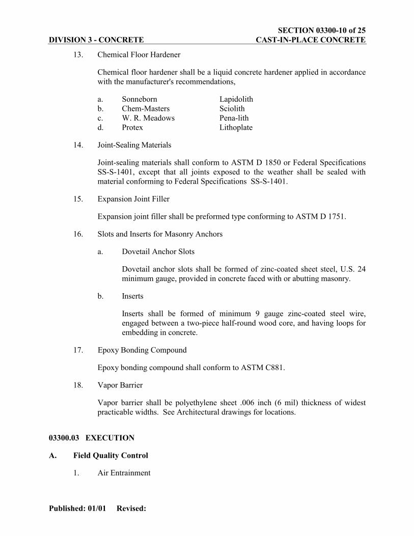
13. Chemical Floor Hardener
Chemical floor hardener shall be a liquid concrete hardener applied in accordance with the manufacturer's recommendations,
a. Sonneborn Lapidolith b. Chem-Masters Sciolith c. W. R. Meadows Pena-lith d. Protex Lithoplate
14. Joint-Sealing Materials
Joint-sealing materials shall conform to ASTM D 1850 or Federal Specifications SS-S-1401, except that all joints exposed to the weather shall be sealed with material conforming to Federal Specifications SS-S-1401.
15. Expansion Joint Filler
Expansion joint filler shall be preformed type conforming to ASTM D 1751.
16. Slots and Inserts for Masonry Anchors
a. Dovetail Anchor Slots
Dovetail anchor slots shall be formed of zinc-coated sheet steel, U.S. 24 minimum gauge, provided in concrete faced with or abutting masonry.
b. Inserts
Inserts shall be formed of minimum 9 gauge zinc-coated steel wire, engaged between a two-piece half-round wood core, and having loops for embedding in concrete.
17. Epoxy Bonding Compound
Epoxy bonding compound shall conform to ASTM C881.
18. Vapor Barrier
Vapor barrier shall be polyethylene sheet .006 inch (6 mil) thickness of widest practicable widths. See Architectural drawings for locations.
03300.03 EXECUTION
A. Field Quality Control
1. Air Entrainment

SECTION 03300-11 of 25 DIVISION 3 - CONCRETE CAST-IN-PLACE CONCRETE
Published: 01/01 Revised:
Determine the air content of concrete in accordance with the recommendations of ASTM C231.
2. Testing of Concrete
a. General Requirements
1) Furnish molds and concrete required for casting specimens and testing. In addition, furnish to the Engineer the necessary standard testing equipment and tools to perform sampling, slump tests, air-entrainment tests, yield tests, and boxes for shipping samples.
2) Compressive strength tests will be performed by the Contractor by making not less than one set of standard cylindrical test specimens for the first 5 cubic yards and every 25 cubic yards of concrete or any portion thereafter for each structure.
3) For each work shift, when concrete is delivered, at least one set of specimens will be made. A set of test specimens will consist of at least six standard cylinders from a batch. At least two specimens of the set will be tested for 2-day, 7-day, and 28-day compressive strength. The tests for 2-day compressive strength, approximately 25 percent of the 28-day compressive strength, will be used to aid in the determination of form, falsework and centering removal. The tests for 7-day compressive strength, approximately 60 percent of the 28-day compressive strength, will be likewise used.
4) Slump tests, yield tests, and air content tests will be performed by the Contractor with no less frequency than that of casting strength specimen sets.
b. Concrete Strengths
1) Determine compressive strengths from standard test specimens taken according to ASTM C31 and ASTM C172, and cured and tested in accordance with ASTM C39 by the Laboratory. Core drilling and testing will be in accordance with ASTM C94.
2) Compute and evaluate in accordance with ASTM C94.
c. Air content: Determine in accordance with ASTM C231.
d. Cement Factor: Determine in accordance with ASTM C138.
e. Modulus of elasticity
Determine the modulus of elasticity and Poisson's Ratio in accordance with ASTM C469 as directed by the Engineer.
SECTION 03300-12 of 25 DIVISION 3 - CONCRETE CAST-IN-PLACE CONCRETE
Published: 01/01 Revised:
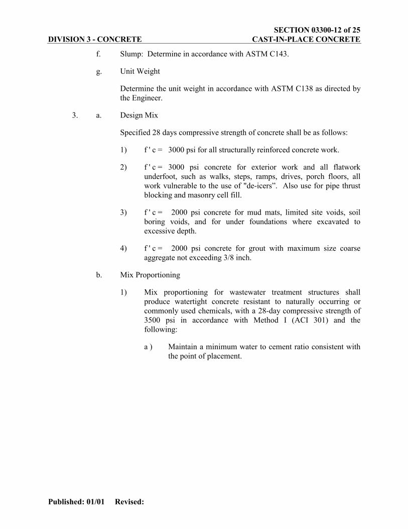
f. Slump: Determine in accordance with ASTM C143.
g. Unit Weight
Determine the unit weight in accordance with ASTM C138 as directed by the Engineer.
3. a. Design Mix
Specified 28 days compressive strength of concrete shall be as follows:
1) f ' c = 3000 psi for all structurally reinforced concrete work.
2) f ' c = 3000 psi concrete for exterior work and all flatwork underfoot, such as walks, steps, ramps, drives, porch floors, all work vulnerable to the use of "de-icers”. Also use for pipe thrust blocking and masonry cell fill.
3) f ' c = 2000 psi concrete for mud mats, limited site voids, soil boring voids, and for under foundations where excavated to excessive depth.
4) f ' c = 2000 psi concrete for grout with maximum size coarse aggregate not exceeding 3/8 inch.
b. Mix Proportioning
1) Mix proportioning for wastewater treatment structures shall produce watertight concrete resistant to naturally occurring or commonly used chemicals, with a 28-day compressive strength of 3500 psi in accordance with Method I (ACI 301) and the following:
a ) Maintain a minimum water to cement ratio consistent with the point of placement.
SECTION 03300-13 of 25 DIVISION 3 - CONCRETE CAST-IN-PLACE CONCRETE
Published: 01/01 Revised:
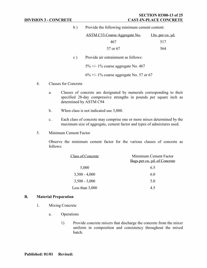
b ) Provide the following minimum cement content:
ASTM C33 Coarse Aggregate No. Lbs. per cu. yd.
467 517
57 or 67 564
c ) Provide air entrainment as follows:
5% +/- 1% coarse aggregate No. 467
6% +/- 1% coarse aggregate No. 57 or 67
4. Classes for Concrete
a. Classes of concrete are designated by numerals corresponding to their specified 28-day compressive strengths in pounds per square inch as determined by ASTM C94
b. When class is not indicated use 3,000.
c. Each class of concrete may comprise one or more mixes determined by the maximum size of aggregate, cement factor and types of admixtures used.
5. Minimum Cement Factor
Observe the minimum cement factor for the various classes of concrete as follows:
Class of Concrete Mimimum Cement Factor Bags per cu. yd. of Concrete
5,000 6.5
3,500 - 4,000 6.0
3,500 - 3,000 5.0
Less than 3,000 4.5
B. Material Preparation
1. Mixing Concrete
a. Operations
1) Provide concrete mixers that discharge the concrete from the mixer uniform in composition and consistency throughout the mixed batch.

SECTION 03300-14 of 25 DIVISION 3 - CONCRETE CAST-IN-PLACE CONCRETE
Published: 01/01 Revised:
2) Do not use fine aggregates from different sources of supply alternatively in the same class of construction mix.
3) Combine coarse aggregates of different gradation and identical sources, providing the corresponding concrete mix has been approved by the Engineer. The use of alternate batches of gravel, crushed gravel, or crushed stone of any one size will not be permitted.
4) The adequacy of mixing will be determined by the Engineer by mixer performance tests according to the Bureau of Reclamation Designation 26 Variability of Constituents in Concrete in the appendix of Concrete Manual of U.S. Bureau of Reclamation, Seventh edition.
5) The Engineer reserves the right to reduce the size of the batch to be mixed or to increase the mixing time when the charging and mixing operations fail to produce a concrete batch which conforms to the above criteria.
6) Add water prior to, during, and following the mixer charging operations. Do not use concrete which is retained in mixers so long as to require additional water in excess of design mix water to permit satisfactory placing.
b. Central-mixed concrete
1) Arrange mixers in centralized mixing plant so that the mixing action in the mixers can be observed by the Engineer and plant operator from a location convenient to the mixing plant operator's station.
2) Do not load mixers in excess of their rated capacity. Mix the concrete ingredients in a batch mixer for not less than the period of time herein specified for various mixer capacities after all of the ingredients except the full amount of water are in the mixer. Reduce the mixing time if thorough mixing as herein defined can be obtained in less time, as determined by the Engineer.

SECTION 03300-15 of 25 DIVISION 3 - CONCRETE CAST-IN-PLACE CONCRETE
Published: 01/01 Revised:
Capacity of Mixer Mixing Time
2 cu. yd. or less 1½ minutes
3 cu. yd 2 minutes
4 cu. yd. 2½ minutes
Larger than 4 cu. yd. To be determined by mixer performance tests by Engineer.
Equip each mixer with a mechanically operated batch counter, and a timing and signaling device which will indicate completion of the required mixing period.
c. Truck-mixed concrete: Use equipment and procedures that conform to the requirements of ASTM C94.
d. Temperature control:
1) Use preparation methods capable of producing concrete with a temperature not more than 90 degrees F. and not less than 45 degrees F. at the time of placement.
2) Do not heat concrete ingredients to a temperature higher than that necessary to keep the temperature of the mixed concrete as placed, within the specified temperatures.
3) Do not allow cement to contact water or aggregate in excess of 120 degrees F.
2. Admixtures
a. Air entraining admixture: Use for concrete exposed to weathering or in contact with rock or moist soil.
b. Chemical admixtures:
1) Use water reducing admixtures in concrete areas below grade in contact with rock, earth, or fill.
2) Employ admixtures without interfering with the specified air content dosage of air-entrained concrete.
3) Except as specified, use water reducing, set retarding or set accelerating admixtures only with the Engineer's approval.
SECTION 03300-16 of 25 DIVISION 3 - CONCRETE CAST-IN-PLACE CONCRETE
Published: 01/01 Revised:
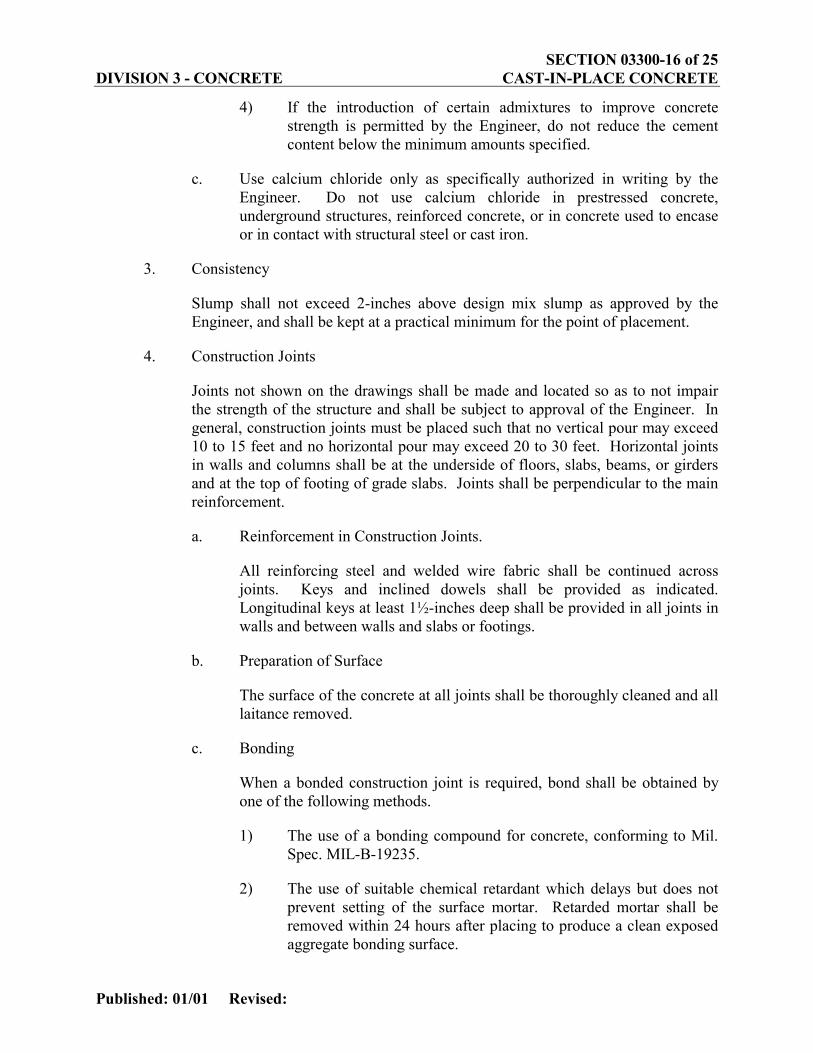
4) If the introduction of certain admixtures to improve concrete strength is permitted by the Engineer, do not reduce the cement content below the minimum amounts specified.
c. Use calcium chloride only as specifically authorized in writing by the Engineer. Do not use calcium chloride in prestressed concrete, underground structures, reinforced concrete, or in concrete used to encase or in contact with structural steel or cast iron.
3. Consistency
Slump shall not exceed 2-inches above design mix slump as approved by the Engineer, and shall be kept at a practical minimum for the point of placement.
4. Construction Joints
Joints not shown on the drawings shall be made and located so as to not impair the strength of the structure and shall be subject to approval of the Engineer. In general, construction joints must be placed such that no vertical pour may exceed 10 to 15 feet and no horizontal pour may exceed 20 to 30 feet. Horizontal joints in walls and columns shall be at the underside of floors, slabs, beams, or girders and at the top of footing of grade slabs. Joints shall be perpendicular to the main reinforcement.
a. Reinforcement in Construction Joints.
All reinforcing steel and welded wire fabric shall be continued across joints. Keys and inclined dowels shall be provided as indicated. Longitudinal keys at least 1½-inches deep shall be provided in all joints in walls and between walls and slabs or footings.
b. Preparation of Surface
The surface of the concrete at all joints shall be thoroughly cleaned and all laitance removed.
c. Bonding
When a bonded construction joint is required, bond shall be obtained by one of the following methods.
1) The use of a bonding compound for concrete, conforming to Mil. Spec. MIL-B-19235.
2) The use of suitable chemical retardant which delays but does not prevent setting of the surface mortar. Retarded mortar shall be removed within 24 hours after placing to produce a clean exposed aggregate bonding surface.

SECTION 03300-17 of 25 DIVISION 3 - CONCRETE CAST-IN-PLACE CONCRETE
Published: 01/01 Revised:
3) By roughening the surface of the concrete in proper manner which will expose the aggregate uniformly and completely expose fresh concrete at the surface.
5. Expansion Joints, Cleavage Joints, Waterstops and Embedded Items.
a. Expansion Joints and Cleavage Joints
Expansion joints shall be provided in any structure having a dimension of 120 feet in any principal direction. Desirable maximum spacing is 50 to 60 feet. Reinforcement shall stop 2 inches from the face of an expansion joint.
Expansion joints and cleavage joints shall not be less than ½-inch wide except as indicated otherwise. Expansion joints not exposed to weather shall be filled completely with preformed joint material conforming to ASTM D 1751. Expansion joints exposed to weather and cleavage joints between vertical masonry surfaces and floor slabs laid on earth shall be filled to a depth of one-inch from the surface or face of the concrete width deep space above the preformed material conforming to ASTM D 1751. The one-inch deep space above the preformed material shall be cleaned after the concrete has been cured, and when dry, filled flush with joint sealing material. Reinforcement or other embedded metal items bonded to the concrete, except dowels in floors bonded on only one side of joint, shall not be permitted to extend continuously through any expansion joints.
b. Waterstops
All horizontal and vertical construction and expansion joints providing for fluid containment in a wet space as well as joints located in exterior walls below grade shall have placed in the joint a waterstop to develop effective watertightness. Wet space shall include tanks, channels, chambers, etc. used to store, convey or contain fluids or solids containing fluids.
The material, design, and location of waterstops in construction joints and expansion joints shall be as indicated or as specified herein. Each piece of premolded waterstop shall be maximum practicable length in order the number of end joints will be held to a minimum. Joints at intersections and at ends of pieces shall be made in the manner most appropriate to the material being used. Joints shall develop effective watertightness fully equal to that of the continuous waterstop material and shall permanently develop not less than 50 percent of the mechanical strength of the parent section and shall permanently retain its flexibility.

SECTION 03300-18 of 25 DIVISION 3 - CONCRETE CAST-IN-PLACE CONCRETE
Published: 01/01 Revised:
c. Embedded Items
All sleeves, inserts, anchors, and embedded items required for adjoining work or for its support shall be placed prior to concreting. All sub-contractors, whose work is related to the concrete or must be supported by it, shall be given ample notice and opportunity to introduce or furnish embedded items before the concrete is placed. All ferrous metal sleeves, inserts, anchors, and other embedded ferrous items exposed to the weather or where rust would impair the appearance or finish of the structure shall be galvanized.
d. Placing Embedded Items
Expansion joint material, waterstops, and embedded items shall be positioned accurately and supported against displacement. Voids in sleeves, inserts, and anchor slots shall be filled temporarily with readily removable material to prevent the entry of concrete into the voids. Aluminum shall not be embedded in concrete except where aluminum is protected from direct contact with the concrete.
e. Reinforcing Bars
Bars may be moved as necessary to avoid interference with other reinforcing steel, conduits, or embedded items, but not so as to impair design strengths of the members. If bars are moved more than one bar diameter, the resulting arrangement of bars shall be subject to the approval of the Engineer.
C. Conveying
1. General Requirements:
a. Convey concrete from the point of delivery with a continuous flow of concrete to the point of placement without segregation.
b. Provide an arrangement at the discharge end of a conveyor to prevent segregation.
2. Chutes and Troughs:
a. Use only ferrous metal or approved plastic or rubber lined chutes and open troughs. Where steep slopes are required, discharge the concrete into a hopper. Keep chutes or open troughs clean of hardened concrete by thoroughly flushing with water after each use.
b. Discharge the water used for cleaning outside the lines of the structure.
SECTION 03300-19 of 25 DIVISION 3 - CONCRETE CAST-IN-PLACE CONCRETE
Published: 01/01 Revised:
3. Adjustable Length Pipes (Elephant Trunks):
a. Use flexible pipes only of ferrous metal, rubber or plastic, six inches minimum diameter and use in a manner that will not cause segregation of the concrete.
b. Locate chute or flexible pipes so that concrete is delivered in a continuous flow to points not more than five feet horizontally and five feet vertically from its final location.
c. Thoroughly clean flexible pipes or elephant trucks after each use.
4. Buggies:
Construct runways on which buggies will operate such that they will not come in contact with or be supported by the reinforcing steel of the structure.
5. Pumping Equipment:
a. Use pumping equipment, designed to handle the types, classes and volumes of concrete to be conveyed without segregation.
b. Operate the pump equipment so that a continuous stream of concrete without air pockets is conveyed. Position the discharge end of the line as near the final position of the concrete as possible.
D. Preparation For Placement
Do not place concrete until all formwork, steel reinforcement, installation of embedded parts, preparations for finishing unformed areas, scaffolding, lighting, power and methods and procedures for placing concrete have been accepted and an instrument check of vertical alignment and bracing sufficient to insure plumbness during pour has been approved by the Engineer. All surfaces of forms and embedded materials shall be cleaned of dried mortar or grout from previous pours. Poorly consolidated concrete at construction joints and all loose material shall be removed. Surfaces of concrete and embedded materials shall be cleaned of laitance, or oil and other bond destroying agents.
Surfaces against which concrete is to be placed shall be clean and free of running water, mud, loose material, oil debris, frost and ice. Rock surfaces shall be free of semi-detached and unsound fragments. Absorptive foundation surfaces shall be moistened thoroughly or otherwise treated so that moisture will not be drawn from freshly placed concrete.
Coat faces of removable concrete forms with form oil acceptable to the Engineer.
SECTION 03300-20 of 25 DIVISION 3 - CONCRETE CAST-IN-PLACE CONCRETE
Published: 01/01 Revised:
E. Placement
1. General Requirements
a. Place concrete continuously and as soon as possible after mixing. Do not use vibrators for shifting the mass of fresh concrete.
b. Place concrete in layers of such thickness that no concrete will be deposited on concrete which has hardened sufficiently to cause the formation of seams or planes of weakness. Cover each layer of concrete with fresh concrete within 45 minutes.
c. Do not place concrete which has attained its initial set or concrete which has contained its mix water for more than 90 minutes.
d. Notify the Engineer at least 24 hours in advance of the start of concrete placing.
e. Placing will not be permitted when, in the opinion of the Engineer, the sun heat, wind or limitations of facilities furnished prevent proper finishing and curing.
f. Control concrete temperature at time of placement:
1) To be not less than 45 degrees F.
2) To be not more than 90 degrees F.
g. Unless approved by the Engineer, do not start concreting when descending natural air temperature falls lower than 40 degrees F.
h. Start placement of structural concrete on/or next to a construction joint with a 3-inch thick layer of oversanded mix with 3/4-inch maximum aggregate, an extra sack of cement per cubic yard, and a five inch slump.
i. Deposit concrete as nearly as practicable directly in its final position so that the lateral movement will not result in segregation of the coarse aggregate, mortar, or water from the concrete mass. Do not use methods and equipment in depositing concrete in forms which result in clusters or groups of coarse aggregate being separated from the concrete mass. When concrete is placed through a dropchute, use one or more vibrators where concrete is falling to prevent stacking and separation.
j. Place formed concrete, in continuous, approximate horizontal layers, the depth of which generally shall not exceed 24-inches. Lesser depths may be required where necessary to ensure that each new layer can be made monolithic with the previous layer by penetration of the vibrators.
SECTION 03300-21 of 25 DIVISION 3 - CONCRETE CAST-IN-PLACE CONCRETE
Published: 01/01 Revised:
2. Compaction
a. Consolidate all concrete by vibration to the maximum practicable density, so that it is free from pockets of coarse aggregate and entrapped air, and filled tightly against the subgrade of previously placed concrete, all formed surfaces and embedded materials. In consolidating each layer of concrete operate the vibrator at regular and frequent intervals, and in a near vertical position. Allow the vibrating head to penetrate and revibrate concrete in the upper zone of the underlying layers.
b. Revibrate the top layer of each placement systematically at the latest time the concrete can be made plastic by means of vibration. Do not place layers of concrete until the layers previously placed have been vibrated thoroughly as specified.
c. Consolidate concrete by electric or pneumatic drive vibrators of sufficient power and capacity to consolidate the concrete effectively and quickly. Operate concrete vibrators at speeds of at least 7,000 rpm when immersed in the concrete. Have standby vibrators in good condition readily available if needed during concrete placement. Use equipment capable of obtaining results and operating reliably and effectively with a concrete mix that is not excessively oversanded or high in slump and may occasionally be of lower slump than intended.
F. Curing And Protecting
1. General Requirements
a. Protect freshly placed concrete from excessive hot or cold temperatures. Maintain concrete surfaces without drying for the period of time necessary for the hydration of the cement and the proper hardening of the concrete.
b. Cure newly placed concrete for a cumulative period of seven days at an air temperature in excess of 55 degrees F.
c. During the curing period keep steel and wood forms set. If forms are removed during curing use one of the following methods of curing immediately and continue for the remainder of the curing period.
2. Normal Curing And Protection
Use any one of the methods specified below:
a. Use ponding on horizontal surfaces providing the surface is submerged at all times for the required curing period.
b. Apply continuous sprinkling with nozzle or nozzles which, during the first 24 hours, atomizes the flow of water providing a mist and not a spray. Do
SECTION 03300-22 of 25 DIVISION 3 - CONCRETE CAST-IN-PLACE CONCRETE
Published: 01/01 Revised:
not apply the moisture under pressure directly upon the concrete and avoid flowing or washing on the surfaces while susceptible to erosion.
c. Cover the entire surface of the concrete with double thickness burlap sheet, laid directly on the concrete and kept wet at all times. Maintain in good condition.
d. Sprinkle, as specified above, for at least 18 hours and then immediately cover the concrete surface with waterproof curing sheets, free from holes or tears. Hold in position in such manner that the entire surface of the concrete being cured is fully covered at all times.
e. Do not damage burlap or waterproof sheet or concrete surfaces.
3. Membrane-Forming Curing Compound
a. Use a curing compound when authorized for circumstances where the application of moisture is impracticable and where such compounds will not jeopardize the appearance of the concrete. Except as otherwise specified, use Type 1 compound, uniformly applied over the surface at the thickness recommended by the manufacturer. Thoroughly mix compound and apply within one hour after mixing.
b. Where the surfaces are subject to sunlight, apply Type 2 White compounds.
c. Do not apply wax-resin type curing compounds to a surface where bond is required for additional concrete or where a bonded surface coating such as paint, tile, dampproofing, waterproofing, or roofing is to be applied.
d. Warm the curing compound if required for satisfactory application in accordance with the manufacturer's recommendations. If the film of the compound is damaged before the expiration of the curing period, repair immediately with additional compound.
e. Give surfaces the required surface finish prior to the application of the curing compound. Do not use curing compound on construction joints.
f. Apply curing compound in two coats, apply the first coat immediately after stripping of forms and acceptance of the concrete finish.
g. If the surface is dry, thoroughly wet the concrete with water and apply the curing compound just as the surface film of water disappears. Apply the second coat after the first coat has set.
h. Protect the coating against damage for a period of at least 10 days after application. Apply an additional coating to coatings which are damaged.
SECTION 03300-23 of 25 DIVISION 3 - CONCRETE CAST-IN-PLACE CONCRETE
Published: 01/01 Revised:
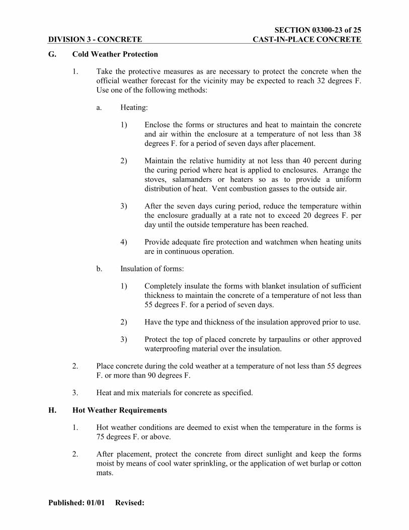
G. Cold Weather Protection
1. Take the protective measures as are necessary to protect the concrete when the official weather forecast for the vicinity may be expected to reach 32 degrees F. Use one of the following methods:
a. Heating:
1) Enclose the forms or structures and heat to maintain the concrete and air within the enclosure at a temperature of not less than 38 degrees F. for a period of seven days after placement.
2) Maintain the relative humidity at not less than 40 percent during the curing period where heat is applied to enclosures. Arrange the stoves, salamanders or heaters so as to provide a uniform distribution of heat. Vent combustion gasses to the outside air.
3) After the seven days curing period, reduce the temperature within the enclosure gradually at a rate not to exceed 20 degrees F. per day until the outside temperature has been reached.
4) Provide adequate fire protection and watchmen when heating units are in continuous operation.
b. Insulation of forms:
1) Completely insulate the forms with blanket insulation of sufficient thickness to maintain the concrete of a temperature of not less than 55 degrees F. for a period of seven days.
2) Have the type and thickness of the insulation approved prior to use.
3) Protect the top of placed concrete by tarpaulins or other approved waterproofing material over the insulation.
2. Place concrete during the cold weather at a temperature of not less than 55 degrees F. or more than 90 degrees F.
3. Heat and mix materials for concrete as specified.
H. Hot Weather Requirements
1. Hot weather conditions are deemed to exist when the temperature in the forms is 75 degrees F. or above.
2. After placement, protect the concrete from direct sunlight and keep the forms moist by means of cool water sprinkling, or the application of wet burlap or cotton mats.
SECTION 03300-24 of 25 DIVISION 3 - CONCRETE CAST-IN-PLACE CONCRETE
Published: 01/01 Revised:
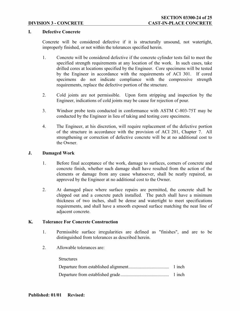
I. Defective Concrete
Concrete will be considered defective if it is structurally unsound, not watertight, improperly finished, or not within the tolerances specified herein.
1. Concrete will be considered defective if the concrete cylinder tests fail to meet the specified strength requirements at any location of the work. In such cases, take drilled cores at locations specified by the Engineer. Core specimens will be tested by the Engineer in accordance with the requirements of ACI 301. If cored specimens do not indicate compliance with the compressive strength requirements, replace the defective portion of the structure.
2. Cold joints are not permissible. Upon form stripping and inspection by the Engineer, indications of cold joints may be cause for rejection of pour.
3. Windsor probe tests conducted in conformance with ASTM C-803-75T may be conducted by the Engineer in lieu of taking and testing core specimens.
4. The Engineer, at his discretion, will require replacement of the defective portion of the structure in accordance with the provision of ACI 201, Chapter 7. All strengthening or correction of defective concrete will be at no additional cost to the Owner.
J. Damaged Work
1. Before final acceptance of the work, damage to surfaces, corners of concrete and concrete finish, whether such damage shall have resulted from the action of the elements or damage from any cause whatsoever, shall be neatly repaired, as approved by the Engineer at no additional cost to the Owner.
2. At damaged place where surface repairs are permitted, the concrete shall be chipped out and a concrete patch installed. The patch shall have a minimum thickness of two inches, shall be dense and watertight to meet specifications requirements, and shall have a smooth exposed surface matching the neat line of adjacent concrete.
K. Tolerance For Concrete Construction
1. Permissible surface irregularities are defined as "finishes", and are to be distinguished from tolerances as described herein.
2. Allowable tolerances are:
Structures
Departure from established alignment.................................... 1 inch
Departure from established grade........................................... 1 inch
SECTION 03300-25 of 25 DIVISION 3 - CONCRETE CAST-IN-PLACE CONCRETE
Published: 01/01 Revised:
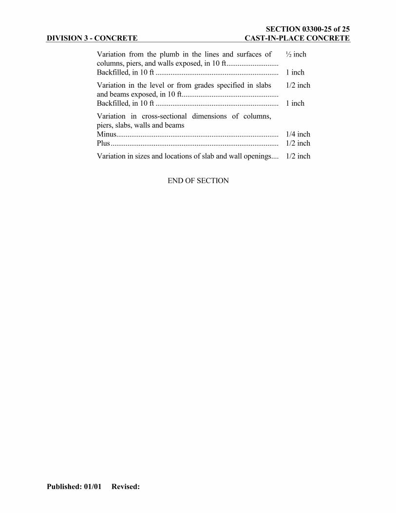
Variation from the plumb in the lines and surfaces of columns, piers, and walls exposed, in 10 ft............................
½ inch
Backfilled, in 10 ft .................................................................. 1 inch
Variation in the level or from grades specified in slabs and beams exposed, in 10 ft....................................................
1/2 inch
Backfilled, in 10 ft .................................................................. 1 inch
Variation in cross-sectional dimensions of columns, piers, slabs, walls and beams
Minus....................................................................................... 1/4 inch Plus.......................................................................................... 1/2 inch
Variation in sizes and locations of slab and wall openings.... 1/2 inch
END OF SECTION
![03300-Cast-In-Place Concrete [spc] - Climatech Incclimatech.com/jobs/St Vincent Physics Center/Project... · Web viewGrout for leveling plates for steel columns and base plates for](https://img.pdfslide.us/doc/110x75/5e56418760c0414ea6390766/03300-cast-in-place-concrete-spc-climatech-vincent-physics-centerproject.jpg)