Embed Size (px)
Citation preview
SECTION 03 30 00CAST-IN-PLACE CONCRETE
PART 1 - GENERAL
1.1 RELATED DOCUMENTS
A. Drawings and general provisions of the Contract, including General andSupplementary Conditions and Division 01 Specification Sections, apply to thisSection.
1.2 SUMMARY
A. Section includes cast-in-place concrete, including formwork, reinforcement,concrete materials, mixture design, placement procedures, and finishes, for thefollowing:
1. Footings.2. Foundation walls.3. Slabs-on-grade.4. Suspended slabs.5. Concrete toppings.6. Building frame members.7. Building walls.
1.3 DEFINITIONS
A. Cementitious Materials: Portland cement alone or in combination with one ormore of the following: blended hydraulic cement, fly ash and other pozzolans,ground granulated blast-furnace slag, and silica fume; subject to compliance withrequirements.
1.4 ACTION SUBMITTALS
A. Product Data: For each type of product indicated.
B. Design Mixtures: For each concrete mixture. Submit alternate design mixtureswhen characteristics of materials, Project conditions, weather, test results, or othercircumstances warrant adjustments.
1. Indicate amounts of mixing water to be withheld for later addition atProject site.
2. Water/cement ratio (total gallons of water per cubic yard).3. Brand, type, and quantity of cement.4. Type and quantity of aggregates.5. Type and quantity of admixtures.6. Type, composition, and quantity of fly ash, slag (GGBFS), or silica fume.
03 30 00 - 1Cast-In-Place Concrete Bid SetTt#200-11740-10003 Teka Tech,Inc.
7. Unit weight (wet density).8. Composition strength based on 28-day compression test.
C. Steel Reinforcement Shop Drawings: Placing drawings that detail fabrication,bending, and placement. Include bar sizes, lengths, material, grade, bar schedules,stirrup spacing, bent bar diagrams, bar arrangement, splices and laps, mechanicalconnections, tie spacing, hoop spacing, and supports for concrete reinforcement.
D. Formwork Shop Drawings: Prepared by or under the supervision of a qualifiedprofessional engineer detailing fabrication, assembly, and support of formwork.
1. Shoring and Reshoring: Indicate proposed schedule and sequence ofstripping formwork, shoring removal, and reshoring installation andremoval.
E. Construction Joint Layout: Indicate proposed construction joints required toconstruct the structure.
1. Location of construction joints is subject to approval of the Engineer.
F. Samples: For waterstops vapor retarder.
1.5 INFORMATIONAL SUBMITTALS
A. Qualification Data: For Installer manufacturer testing agency.
B. Welding certificates.
C. Material Certificates: For each of the following, signed by manufacturers:
1. Cementitious materials.2. Admixtures.3. Form materials and form-release agents.4. Steel reinforcement and accessories.5. Fiber reinforcement.6. Waterstops.7. Curing compounds.8. Floor and slab treatments.9. Bonding agents.10. Adhesives.11. Vapor retarders.12. Joint-filler strips.13. Repair materials.
D. Material Test Reports: For the following, from a qualified testing agency,indicating compliance with requirements:
03 30 00 - 2Cast-In-Place Concrete Bid SetTt#200-11740-10003 Teka Tech,Inc.
1. Aggregates. Include service record data indicating absence of deleteriousexpansion of concrete due to alkali aggregate reactivity.
E. Submit laboratory test reports for concrete mix design, aggregates (particularlydeleterious materials in coarse aggregate) and fly ash, slag (GGBFS) and silicafume (if used) 4 weeks before scheduled pouring.
F. Floor surface flatness and levelness measurements indicating compliance withspecified tolerances.
G. Field quality-control reports.
1. Submit written reports to ENGINEER documenting testing and inspectionresults. Prepare report as noted in Section 01 45 16.13.
2. Submit mill test reports on reinforcement.3. Submit materials certificates in lieu of laboratory test reports on other
materials. Manufacturer and CONTRACTOR shall sign materialcertificates certifying that each material item complies with, or exceeds,specified requirements. Submit certification from admixturemanufacturers that chloride content complies with specificationrequirements.
H. Minutes of preinstallation conference.
1.6 QUALITY ASSURANCE
A. Installer Qualifications: A qualified installer who employs on Project personnelqualified as ACI-certified Flatwork Technician and Finisher and a supervisor whois an ACI-certified Concrete Flatwork Technician.
B. Manufacturer Qualifications: A firm experienced in manufacturing ready-mixedconcrete products and that complies with ASTMC94/C94M requirements forproduction facilities and equipment.
1. Manufacturer certified according to NRMCA's "Certification of ReadyMixed Concrete Production Facilities."
C. Testing Agency Qualifications: An independent agency, acceptable to authoritieshaving jurisdiction, qualified according to ASTM C 1077 and ASTM E 329 fortesting indicated.
1. Personnel conducting field tests shall be qualified as ACI Concrete FieldTesting Technician, Grade 1, according to ACI CP-1 or an equivalentcertification program.
2. Personnel performing laboratory tests shall be ACI-certified ConcreteStrength Testing Technician and Concrete Laboratory Testing Technician- Grade I. Testing Agency laboratory supervisor shall be an ACI-certifiedConcrete Laboratory Testing Technician - Grade II.
03 30 00 - 3Cast-In-Place Concrete Bid SetTt#200-11740-10003 Teka Tech,Inc.
D. Source Limitations: Obtain each type or class of cementitious material of thesame brand from the same manufacturer's plant, obtain aggregate from singlesource, and obtain admixtures from single source from single manufacturer.
E. Welding Qualifications: Qualify procedures and personnel according toAWS D1.4/D 1.4M, "Structural Welding Code - Reinforcing Steel."
F. ACI Publications: Comply with the following unless modified by requirements inthe Contract Documents:
1. ACI 301, "Specifications for Structural Concrete," Sections 1 through 5.2. ACI 117, "Specifications for Tolerances for Concrete Construction and
Materials."
G. Concrete Testing Service: Engage a qualified independent testing agency toperform material evaluation tests and to design concrete mixtures.
H. Preinstallation Conference: Conduct conference at Project site.
1. Before submitting design mixtures, review concrete design mixture andexamine procedures for ensuring quality of concrete materials. Requirerepresentatives of each entity directly concerned with cast-in-placeconcrete to attend, including the following:
a. Contractor's superintendent.b. Independent testing agency responsible for concrete design
mixtures.c. Ready-mix concrete manufacturer.d. Concrete subcontractor.e. Special concrete finish subcontractor.
2. Review special inspection and testing and inspecting agency proceduresfor field quality control, concrete finishes and finishing, cold- and hot-weather concreting procedures, curing procedures, constructioncontraction and isolation joints, and joint-filler strips, semirigid jointfillers, forms and form removal limitations, vapor-retarder installation,anchor rod and anchorage device installation tolerances, steelreinforcement installation, floor and slab flatness and levelnessmeasurement, concrete repair procedures, and concrete protection.
1.7 DELIVERY, STORAGE, AND HANDLING
A. Steel Reinforcement: Deliver, store, and handle steel reinforcement to preventbending and damage.
B. Waterstops: Store waterstops under cover to protect from moisture, sunlight, dirt,oil, and other contaminants.
03 30 00 - 4Cast-In-Place Concrete Bid SetTt#200-11740-10003 Teka Tech,Inc.
1.8 PROJECT CONDITIONS
A. Protection of Footings against Freezing: Cover completed Work at footing levelwith sufficient temporary or permanent cover to protect footings and adjacentsubgrade against possibility of freezing. Maintain cover for curing period or untiltemperatures cannot affect concrete footings.
B. Protect adjacent finish materials against spatter during concrete placement.
PART 2 - PRODUCTS
2.1 FORM-FACING MATERIALS
A. Smooth-Formed Finished Concrete: Form-facing panels that will providecontinuous, true, and smooth concrete surfaces. Furnish in largest practicablesizes to minimize number of joints.
1. Plywood, metal, or other approved panel materials.2. Exterior-grade plywood panels, suitable for concrete forms, complying
with DOC PS 1, and as follows:
a. High-density overlay, Class 1 or better.b. Medium-density overlay, Class 1 or better; mill-release agent
treated and edge sealed.c. Structural 1, B-B or better; mill oiled and edge sealed.d. B-B (Concrete Form), Class 1 or better; mill oiled and edge sealed.
B. Rough-Formed Finished Concrete: Plywood, lumber, metal, or another approvedmaterial. Provide lumber dressed on at least two edges and one side for tight fit.
C. Forms for Cylindrical Columns, Pedestals, and Supports: Metal, glass-fiber-reinforced plastic, paper, or fiber tubes that will produce surfaces with gradual orabrupt irregularities not exceeding specified formwork surface class. Provide unitswith sufficient wall thickness to resist plastic concrete loads without detrimentaldeformation.
D. Chamfer Strips: Wood, metal, PVC, or rubber strips, 3/4 by 3/4 inch, minimum.
E. Rustication Strips: Wood, metal, PVC, or rubber strips, kerfed for ease of formremoval.
F. Form-Release Agent: Commercially formulated form-release agent that will notbond with, stain, or adversely affect concrete surfaces and will not impairsubsequent treatments of concrete surfaces.
1. Formulate form-release agent with rust inhibitor for steel form-facingmaterials.
03 3000 - 5Cast-In-Place Concrete Bid SetTt#200-11740-10003 Teka Tech,Inc.
G. Form Ties: Factory-fabricated, removable or snap-off metal or glass-fiber-reinforced plastic form ties designed to resist lateral pressure of fresh concrete onforms and to prevent spalling of concrete on removal.
1. Furnish units that will leave no corrodible metal closer than 1 inch to theplane of exposed concrete surface.
2. Furnish ties with integral water-barrier plates to walls indicated to receivedampproofing or waterproofing.
3. Form ties for water-retaining structures shall have integral waterstops. Apreformed neoprene or polyurethane tapered plug sized to seat at thecenter of the wall shall be inserted in the hole left by the removal of thetaper tie.
2.2 STEEL REINFORCEMENT
A. Reinforcing Bars: ASTM A 615/A 615M, Grade 60, deformed.
B. Plain-Steel Wire: ASTM A 82/A 82M, as drawn.
C. Deformed-Steel Wire: ASTM A 496/A 496M.
D. Plain-Steel Welded Wire Reinforcement: ASTM A 185/A 185M, plain, fabricatedfrom as-drawn steel wire into flat sheets.
2.3 REINFORCEMENT ACCESSORIES
A. Joint Dowel Bars: ASTM A 615/A 615M, Grade 60, plain-steel bars, cut true tolength with ends square and free of burrs. Provide ASTM 1035, Grade 100 whereindicated on the drawings.
B. Bar Supports: Bolsters, chairs, spacers, and other devices for spacing, supporting,and fastening reinforcing bars and welded wire reinforcement in place.Manufacture bar supports from steel wire, plastic, or precast concrete according toCRSI's "Manual of Standard Practice," of greater compressive strength thanconcrete and as follows:
1. For concrete surfaces exposed to view where legs of wire bar supportscontact forms, use CRSI Class 1 plastic-protected steel wire or CRSIClass 2 stainless-steel bar supports.
2.4 CONCRETE MATERIALS
A. Cementitious Material: Use the following cementitious materials, of the sametype, brand, and source, throughout Project:
1. Portland Cement: ASTM C 150, gray, Type I, except use Type III whereapplications require high-early-strength or Type II where required by
03 30 00 - 6Cast-In-Place Concrete Bid SetTt#200-11740-10003 Teka Tech,Inc.
ENGINEER for corrosive environments. Use one brand of cementthroughout Project, unless otherwise acceptable to ENGINEER.
2. Fly Ash: ASTM C 618, Type C or Type F (corrosive environments) withloss on ignition not more than 6 percent.
3. Ground Granulated Blast-Furnace Slag: ASTM C 989.4. Silica Fume: ASTM C 1240, amorphous silica.
B. Normal-Weight Aggregates: ASTM C 33, Class 3M coarse aggregate or better,graded. Provide aggregates from a single source with documented service recorddata of at least 10 years' satisfactory service in similar applications and serviceconditions using similar aggregates and cementitious materials.
1. Maximum Coarse-Aggregate Size: 1-1/2 inches nominal.2. Fine Aggregate: Free of materials with deleterious reactivity to alkali in
cement.
C. Water: ASTM C 94/C 94M.
D. Potable Water Structures: For surfaces in contact with potable water, use onlymaterials approved by Department of Public Health of the state that hasjurisdiction.
2.5 ADMIXTURES
A. Air-Entraining Admixture: ASTM C 260.
B. Chemical Admixtures: Provide admixtures certified by manufacturer to becompatible with other admixtures and that will not contribute water-solublechloride ions exceeding those permitted in hardened concrete. Do not use calciumchloride or admixtures containing calcium chloride.
1. Prohibited Admixtures: Calcium chloride thyocyanates or admixturescontaining more than 0.1 percent chloride ions.
2. Water-Reducing Admixture: ASTM C 494/C 494M, Type A.3. Water-Reducing and Retarding Admixture: ASTM C 494/C 494M,
Type D.4. High-Range, Water-Reducing Admixture: ASTM C 494/C 494M, Type F.5. Water Reducing, Nonchloride Accelerator Admixture: ASTM C 494,
Type E.6. High-Range, Water-Reducing and Retarding Admixture:
ASTM C 494/C 494M, Type G.
2.6 FIBER REINFORCEMENT
A. Synthetic Micro-Fiber: Monofilament polypropylene micro-fibers engineered anddesigned for use in concrete, complying with ASTM C 1116/C 1116M, Type III,1 to 2-1/4 inches long.
03 30 00 - 7Cast-In-Place Concrete Bid SetTt#200-11740-10003 Teka Tech,Inc.
1. Products: Subject to compliance with requirements, available productsthat may be incorporated into the Work include, but are not limited to, thefollowing:
a. Monofilament Micro-Fibers:
1) Axim Italcementi Group, Inc.; Fibrasol II P.2) Euclid Chemical Company (The), an RPM company;
Fiberstrand 150.3) FORTA Corporation; FORTA Econo-Mono.4) Grace Construction Products, W. R. Grace & Co.; Grace
MicroFiber.5) Metalerete Industries; Polystrand 1000.6) Nycon, Inc.; ProConM.7) Propex Concrete Systems Corp.; Fibermesh 150.8) Sika Corporation; Sika Fiber PPM.
2.7 WATERSTOPS
A. Chemically Resistant Flexible Waterstops: Thermoplastic elastomer rubberwaterstops with factory-installed metal eyelets, for embedding in concrete toprevent passage of fluids through joints; resistant to oils, solvents, and chemicals.Factory-fabricate corners, intersections, and directional changes.
1. JP Specialties, Inc.2. Sika Corporation3. Vinylex Waterstop & Accessories4. Westec Barrier Technologies5. Profile: As indicated6. Dimensions: As indicated on the structural drawings.
B. Flexible PVC Waterstops: CE CRD-C 572, for embedding in concrete to preventpassage of fluids through joints. Factory-fabricate corners, intersections, anddirectional changes.
1. BoMetals, Inc2. Paul Murphy Plastics Company3. Sika Corporation4. Vinylex Waterstop & Accessories5. Greenstreak6. Profile: as indicated on the structural drawings.7. Dimensions: as indicated on the structural drawings.
C. Self-Expanding Rubber Strip Waterstops: Manufactured rectangular ortrapezoidal strip, bentonite-free hydrophilic polymer modified chloroprenerubber, for adhesive bonding to concrete, 3/8 by 3/4 inch.
03 30 00 - 8Cast-In-Place Concrete Bid SetTt#200-11740-10003 Teka Tech,Inc.
1. Adeka Ultra Seal/OCM, Inc.2. Sika Corporation3. Vinylex Waterstop & Accesories
2.8 VAPOR RETARDERS
A. Sheet Vapor Retarder: ASTM E 1745, Class B. Include manufacturer'srecommended adhesive or pressure-sensitive tape.
1. Fortifiber Building System2. Raven Industries, Inc.3. Stego Industries, LLC
B. Sheet Vapor Retarder: Polyethylene sheet, ASTM D 4397, not less than 10 milsthick.
2.9 FLOOR AND SLAB TREATMENTS: Refer to specification 09 90 00, Painting andCoating.
2.10 CURING MATERIALS
A. Absorptive Cover: AASHTO M 182, Class 2, burlap cloth made from jute orkenaf, weighing approximately 9 oz./sq. yd. when dry.
B. Moisture-Retaining Cover: ASTM C 171, polyethylene film or white burlap-polyethylene sheet.
C. Water: Potable.
D. Clear, Waterborne, Membrane-Forming Curing Compound: ASTM C 309,Type 1, Class B, nondissipating, certified by curing compound manufacturer tonot interfere with bonding of floor covering.
1. BASF Construction Chemical2. ChemMasters, Inc.3. Dayton Superior4. Euclid Chemical Company5. Kaufman Products, Inc.6. L&M Construction Chemical7. Lambert Corporation8. Metalerete Industries9. Nox-Crete Products Group10. Sika Corporation11. SpecChem12. Symons by Dayton Superior13. TK Products Unitex by Dayton Superior14. Vexcon Chemicals Inc.15. W.R. Meadows, Inc.
03 30 00 - 9Cast-In-Place Concrete Bid SetTt#200-11740-10003 Teka Tech,Inc.
2.11 RELATED MATERIALS
A. Expansion- and Isolation-Joint-Filler Strips: ASTM D 1751, asphalt-saturatedcellulosic fiber or ASTM D 1752, cork or self-expanding cork.
B. Reglets: Fabricate reglets of not less than 0.022-inch-thick, galvanized-steel sheet.Temporarily fill or cover face opening of reglet to prevent intrusion of concrete ordebris.
C. Dovetail Anchor Slots: Hot-dip galvanized-steel sheet, not less than 0.034 inchthick, with bent tab anchors. Temporarily fill or cover face opening of slots toprevent intrusion of concrete or debris.
2.12 REPAIR MATERIALS
A. Repair Underlayment: Cement-based, polymer-modified, self-leveling productthat can be applied in thicknesses from 1/8 inch and that can be feathered at edgesto match adjacent floor elevations.
1. Cement Binder: ASTM C 150, portland cement or hydraulic or blendedhydraulic cement as defined in ASTM C 219.
2. Primer: Product of underlayment manufacturer recommended forsubstrate, conditions, and application.
3. Aggregate: Well-graded, washed gravel, 1/8 to 1/4 inch or coarse sand asrecommended by underlayment manufacturer.
4. Compressive Strength: Not less than 4100 psi at 28 days when testedaccording to ASTM C 109/C 109M.
B. Repair Overlayment: Cement-based, polymer-modified, self-leveling product thatcan be applied in thicknesses from 1/4 inch and that can be filled in over ascarified surface to match adjacent floor elevations.
1. Cement Binder: ASTM C 150, portland cement or hydraulic or blendedhydraulic cement as defined in ASTM C 219.
2. Primer: Product of topping manufacturer recommended for substrate,conditions, and application.
3. Aggregate: Well-graded, washed gravel, 1/8 to 1/4 inch or coarse sand asrecommended by topping manufacturer.
4. Compressive Strength: Not less than 5000 psi at 28 days when testedaccording to ASTM C 109/C 109M.
2.13 CONCRETE MIXTURES, GENERAL
A. Prepare design mixes for each concrete class and strength by either laboratorytrial batch or field experience methods as specified in ACI 301. If trial batchmethod is used, use independent testing facilities acceptable to ENGINEER for
03 30 00 - 10Cast-In-Place Concrete Bid SetTt#200-11740-10003 Teka Tech,Inc.
preparing and reporting proposed mix designs. Testing facility shall not beidentical to that used for field quality control testing.
B. Fly ash shall be used to partially supplant cement content in Class A and Class Sconcrete, unless noted otherwise, and is optional in other classes. Replacementquantity of cement content by weight shall be not less than 15 percent for Class Aand Class S concrete or more than 25 percent for all classes except Class F.
C. For concrete Class A and Class S, concrete mix design with fly ash and silicafume shall be maximum 30 percent of cement content by weight, and shallconstitute no more than 20 and 10 percent, respectively, of the total weight ofcementitious materials.
D. For concrete, Class S, use Portland cement Type II with fly ash, Type F.
E. Ground granulated blast furnace slag (GGBFS) shall only be permitted for massconcrete placement and as approved by ENGINEER. Replacement quantity ofcement content weight shall not be less than 35 percent or more than 50 percent.
F. Coarse aggregate shall be 1-1/2" top size, except for Class G concrete which shallbe 3/8" top size.
G. Design mixes to provide normal weight concrete for following classes andproperties:
1. Locations for concrete classes are as follows:
a. Class A Structural concrete (slabs, walls, columns, beams,equipment bases, and slab toppings 2 inches or greater inthickness).
b. Class SSulfate resistant structural concrete (slabs, walls, columns,and beams) where indicated on Drawings.
c. Class G Grout fill for use in sweeping in final surfaces insanitary structures and slab toppings less than 2 inches inthickness.
d. Class PExterior pavements (unless otherwise indicated onDrawings).
e. Class B Sidewalks and manhole bases (unless otherwiseindicated on Drawings).
f. Cass C Fill within manholes, mud mats, fill under structures,encasement for piping below or adjacent to structures andencasement for floor drains, sewer inlets and similar items.
g. Class FFlowable fill for filling spaces as permitted and directed byENGINEER.
2. Properties for concrete classes are as follows:
03 30 00 - 11Cast-In-Place Concrete Bid SetTt#200-11740-10003 Teka Tech,Inc.
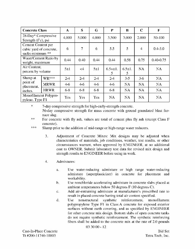
Concrete Class A S G P B C F
28-Day* Compressive 4,000 5,000 4,000 3,500 3,000 2,000 50-100Strength (f'c), psiCement Content percubic yard of concrete, 6 7 6 5.5 5 4 0.4-3.0
sacks minimum **
Water/Cement Ratio by 0.44 0.40 0.44 0.44 0.58 0.75 0.40-0.75weight, maximum
Air Content' 5±1 <4 5±1 6.5+±1. 6.5±1. NA NApercent by volume 5 5
Slump at WR*** 2-4 2-4 2-4 2-4 3-5 3-6 NA
Point of MRWR 4-6 4-6 4-6 4-6 NA NA NAplacement,inches. HRWR 6-8 6-8 6-8 6-8 NA NA NA
Monofilament Polypro- Yes Yes Yes NA NA NA NApylene, Type F1
* 7-day compressive strength for high-early-strength concrete.56-day compressive strength for mass concrete with ground granulated blast fur-nace slag.
** For concrete with fly ash, values are total of cement plus fly ash (except Class Fconcrete).
*** Slump prior to the addition of mid-range or high-range water reducers.
3. Adjustment of Concrete Mixes: Mix designs may be adjusted whencharacteristics of materials, job conditions, weather, test results, or othercircumstances warrant, when approved by ENGINEER, at no additionalcost to OWNER. Submit laboratory test data for revised mix design andstrength results to ENGINEER before using in work.
4. Admixtures:
b.
c.
d.
Cast-In-Place ConcreteTt #200-11740-10003
Use water-reducing admixture or high range water-reducingadmixture (superplasticizer) in concrete for placement andworkability.Use nonchloride accelerating admixture in concrete slabs placed atambient temperatures below 50 degrees F (10 degrees C).Add air-entraining admixture at manufacturer's prescribed rate toresult in placed concrete having total air content specified.Use nonstructural synthetic reinforcement, monofilamentpolypropylene Type F1 in Class A concrete for exposed exteriorsurfaces without earth covering, and as specified by ENGINEERfor other concrete mix design. Bottom slabs of open concrete tanksdo not require synthetic reinforcement. The synthetic reinforcingfibers shall be added to the concrete mix at the rate of 2.0 pounds
03 30 00 - 12Bid Set
Tetra Tech, Inc.
per cubic yard and in accordance with manufacturer'srecommendations.
2.14 FABRICATING REINFORCEMENT
A. Fabricate steel reinforcement according to CRSI's "Manual of Standard Practice."
2.15 CONCRETE MIXING
A. Ready-Mixed Concrete: Measure, batch, mix, and deliver concrete according toASTM C 94/C 94M and ASTM C 1116/C 1116M, and furnish batch ticketinformation.
B. When air temperature is between 85 and 90 deg F, reduce mixing and deliverytime from 1-1/2 hours to 75 minutes; when air temperature is above 90 deg F,reduce mixing and delivery time to 60 minutes.
PART 3 - EXECUTION
3.1 FORMWORK
A. Design, erect, shore, brace, and maintain formwork, according to ACI 301, tosupport vertical, lateral, static, and dynamic loads, and construction loads thatmight be applied, until structure can support such loads.
B. Construct formwork so concrete members and structures are of size, shape,alignment, elevation, and position indicated, within tolerance limits of ACI 117.
C. Limit concrete surface irregularities, designated by ACI 347 as abrupt or gradual,as follows:
1. Class A, 1/8 inch for smooth-formed finished surfaces.
2. Class B, 1/4 inch for rough-formed finished surfaces.
D. Construct forms tight enough to prevent loss of concrete mortar.
E. Fabricate forms for easy removal without hammering or prying against concretesurfaces. Provide crush or wrecking plates where stripping may damage castconcrete surfaces. Provide top forms for inclined surfaces steeper than 1.5horizontal to 1 vertical.
1. Install keyways, reglets, recesses, and the like, for easy removal.
2. Do not use rust-stained steel form-facing material.
03 30 00 - 13Cast-In-Place Concrete Bid SetTt#200-11740-10003 Teka Tech,Inc.
F. Set edge forms, bulkheads, and intermediate screed strips for slabs to achieverequired elevations and slopes in finished concrete surfaces. Provide and secureunits to support screed strips; use strike-off templates or compacting-type screeds.
G. Provide temporary openings for cleanouts and inspection ports where interior areaof formwork is inaccessible. Close openings with panels tightly fitted to formsand securely braced to prevent loss of concrete mortar. Locate temporaryopenings in forms at inconspicuous locations.
H. Chamfer exterior corners and edges of permanently exposed concrete.
I. Form openings, chases, offsets, sinkages, keyways, reglets, blocking, screeds, andbulkheads required in the Work. Determine sizes and locations from tradesproviding such items.
J. Clean forms and adjacent surfaces to receive concrete. Remove chips, wood,sawdust, dirt, and other debris just before placing concrete.
K. Retighten forms and bracing before placing concrete, as required, to preventmortar leaks and maintain proper alignment.
L. Coat contact surfaces of forms with form-release agent, according tomanufacturer's written instructions, before placing reinforcement.
3.2 EMBEDDED ITEMS
A. Place and secure anchorage devices and other embedded items required foradjoining work that is attached to or supported by cast-in-place concrete. Usesetting drawings, templates, diagrams, instructions, and directions furnished withitems to be embedded.
1. Install anchor rods, accurately located, to elevations required andcomplying with tolerances in Section 7.5 of AISC's "Code of StandardPractice for Steel Buildings and Bridges."
2. Install reglets to receive waterproofing and to receive through-wallflashings in outer face of concrete frame at exterior walls, where flashingis shown at lintels, shelf angles, and other conditions.
3. Install dovetail anchor slots in concrete structures as indicated.
3.3 REMOVING AND REUSING FORMS
A. Vertical Forms not supporting concrete weight may be removed when concretehas sufficiently set to resist damage from removal operation.
03 30 00 - 14Cast-In-Place Concrete Bid SetTt#200-11740-10003 Teka Tech,Inc.
B. Other forms shall be left in place until concrete has attained strength to support itsown weight and construction live loads, unless removed in sections, and eachstructural section immediately reshored.
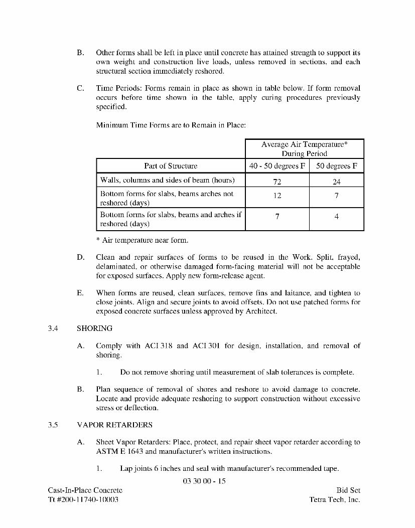
C. Time Periods: Forms remain in place as shown in table below. If form removaloccurs before time shown in the table, apply curing procedures previouslyspecified.
Minimum Time Forms are to Remain in Place:
Average Air Temperature*During Period
Part of Structure 40 - 50 degrees F 50 degrees F
Walls, columns and sides of beam (hours) 72 24
Bottom forms for slabs, beams arches not 12 7reshored (days)
Bottom forms for slabs, beams and arches if 7 4reshored (days)
* Air temperature near form.
D. Clean and repair surfaces of forms to be reused in the Work. Split, frayed,delaminated, or otherwise damaged form-facing material will not be acceptablefor exposed surfaces. Apply new form-release agent.
E. When forms are reused, clean surfaces, remove fins and laitance, and tighten toclose joints. Align and secure joints to avoid offsets. Do not use patched forms forexposed concrete surfaces unless approved by Architect.
3.4 SHORING
A. Comply with ACI 318 and ACI 301 for design, installation, and removal ofshoring.
1. Do not remove shoring until measurement of slab tolerances is complete.
B. Plan sequence of removal of shores and reshore to avoid damage to concrete.Locate and provide adequate reshoring to support construction without excessivestress or deflection.
3.5 VAPOR RETARDERS
A. Sheet Vapor Retarders: Place, protect, and repair sheet vapor retarder according toASTM E 1643 and manufacturer's written instructions.
1. Lap joints 6 inches and seal with manufacturer's recommended tape.
03 30 00 - 15Cast-In-Place Concrete Bid SetTt#200-11740-10003 Teka Tech,Inc.
B. Bituminous Vapor Retarders: Place, protect, and repair bituminous vapor retarderaccording to manufacturer's written instructions.
3.6 STEEL REINFORCEMENT
A. General: Comply with CRSI's "Manual of Standard Practice" for placingreinforcement.
1. Do not cut or puncture vapor retarder. Repair damage and reseal vaporretarder before placing concrete.
B. Clean reinforcement of loose rust and mill scale, earth, ice, and other foreignmaterials that would reduce bond to concrete.
C. Accurately position, support, and secure reinforcement against displacement.Locate and support reinforcement with bar supports to maintain minimumconcrete cover. Do not tack weld crossing reinforcing bars.
D. Set wire ties with ends directed into concrete, not toward exposed concretesurfaces.
E. Install welded wire reinforcement in longest practicable lengths on bar supportsspaced to minimize sagging. Lap edges and ends of adjoining sheets at least onemesh spacing. Offset laps of adjoining sheet widths to prevent continuous laps ineither direction. Lace overlaps with wire.
F. Field bending of reinforcement:
1. Field bending of plain reinforcement shall be performed using anapproved and appropriate sized portable hydraulic device that makes ACI-approved radius bends. No other field bending method shall be permitted.
2. No field bending shall be permitted for epoxy coated reinforcement.
3.7 JOINTS
A. Locate and install construction joints as shown or, if not shown, locate so as not toimpair strength and appearance of structures, at intervals not to exceed 50 feet.For construction joints in water-containing structures or tanks or in water-restraining structures, use watertight joints.
B. Continue reinforcement across construction joints, unless otherwise noted.Mechanical inserts with threaded studs are not accepted as substitutes for through-dowels.
C. Locate construction joints in floor system at or near middle of span in slabs,beams, or girders unless beam intersects girders at this point. Then, where notshown on Drawings, joints in girders shall be offset distances twice the width ofbeams, and provisions made for shear by web reinforcement across joints.
03 30 00 - 16Cast-In-Place Concrete Bid SetTt#200-11740-10003 Teka Tech,Inc.
D. Provide watertight joints to prevent water seepage. Take special care in finishingsurfaces to which succeeding concrete is bonded. Provide waterstops in joints ifshown. Install waterstops to form continuous diaphragm in each joint. Makeprovisions to support and protect exposed waterstops during progress of work.Fabricate field joints in waterstops according to manufacturer's printedinstructions.
E. Provide isolation joints in slabs-on-ground at points of contact between slabs-on-ground and vertical surfaces of column pedestals, foundation walls, and gradebeams.
F. Contraction (Control) Joints in Slabs-on-Ground: Construct contraction (control)joints in slabs-on-ground to form panels of patterns as shown. Use saw cuts 3/16inch by 1/4 slab depth or inserts 1/4-inch wide by 1/4 of slab depth unlessotherwise noted.
G. If joint pattern is not shown, provide joints at 15 feet at most in either direction,with locations to conform to bay spacing wherever practical (at columncenterlines, half-bays, third-bays).
H. Form contraction joints by inserting pre-molded plastic, hardboard, or fiberboardstrip into fresh concrete until top surface of strip is flush with slab surface. Toolslab edges round on each side of insert. After concrete has cured, remove insertsand clean groove of loose debris.
I. Cut contraction joints in unexposed floor slabs by saw cuts as soon as practicalafter slab finishing when it can be safely done without dislodging aggregate.
J. Doweled Joints: Install dowel bars and support assemblies at joints whereindicated. Lubricate or asphalt coat one-half of dowel length to prevent concretebonding to one side of joint.
3.8 INSTALLATION OF EMBEDDED ITEMS
A. Set and build into Work anchorage devices and other embedded items required forother work that are attached to, or supported by, cast-in-place concrete. Usesetting drawings, diagrams, instructions and directions provided by suppliers ofattachment items.
B. Edge Forms and Screed Strips for Slabs: Set edge forms or bulkheads andintermediate screed strips for slabs to obtain set elevations and contours infinished slab surface. Provide and secure units sufficiently strong to supportscreed strips by use of strike-off templates or accepted compacting screeds.
C. Conduits and pipes of aluminum shall not be embedded in structural concreteunless they are effectively coated or covered to prevent aluminum-concretereaction or electrolytic action between aluminum and steel.
03 30 00 - 17Cast-In-Place Concrete Bid SetTt#200-11740-10003 Teka Tech,Inc.
D. PVC Waterstops:
1. Field butt splices shall be heat fused using a Teflon-coatedthermostatically controlled waterstop splicing iron at approximately 380degrees F following manufacturer's recommendations. Lapping ofwaterstop or use of adhesives shall not be allowed.
2. Center the waterstop in joint and secure waterstop in correct position usinghog rings or grommets spaced at 12 inches on center along length ofwaterstop and wire tie to adjacent reinforcing steel. Do not drive nails orotherwise puncture additional holes in the waterstop when forming.
E. Hydrophylic Waterstops:
1. Adhere waterstop to substrate using manufacturer's recommendedadhesive.
2. Tightly butt ends of waterstop together to form a continuous waterstop. Donot lap waterstop.
3. Verify that minimum concrete per manufacturer's recommendations willoccur along waterstop's entire length. Do not install waterstop in keyways.
4. Follow manufacturer's recommended installation procedures.
3.9 PREPARATION OF FORM SURFACES
A. Clean re-used forms of concrete matrix residue, repair and patch to return formsto acceptable surface condition.
B. Coat contact surfaces of forms with form-coating compounds before placingreinforcement.
C. Thin form-coating compounds only with acceptable thinning agents, quantity, andunder conditions of form-coating compound manufacturer's directions. Do notallow excess form-coating material to accumulate in forms or to come into contactwith in-place concrete surfaces against which fresh concrete is placed. Apply incompliance with manufacturer's instructions.
Coat steel forms with non-staining, rust-preventive form oil to protect againstrusting. Rust-stained steel formwork is not acceptable.
3.10 CONCRETE PLACEMENT
A. Before placing concrete, inspect and complete formwork installation, reinforcingsteel, waterstop installation, and other embedded or cast-in items.
1. Notify other crafts to permit installation of their work.2. Cooperate with other trades in setting their work.3. Moisten wood forms immediately before placing concrete where form
coatings are not used.
03 30 00 - 18Cast-In-Place Concrete Bid SetTt#200-11740-10003 Teka Tech,Inc.
4. Apply temporary protective covering to lower 2 feet of finished wallswhere adjacent floor slabs are poured to guard against spattering duringslab placement.
B. Comply with ACI 304R and as specified in this Section.
C. Discharge Concrete at Site within 1-1/2 hours after cement is added to water oraggregates. When air temperature exceeds 85 degrees F, the discharge time shallbe less than 45 minutes. The 45-minute requirement may be waived with the useof a water reducing, retarding admixture and approval of ENGINEER.
D. Provide trip ticket in duplicate for each ready-mixed concrete load delivered,stating truck number, Project name, CONTRACTOR and producer, batchingtime, total yards of concrete and material contained therein. Show ticket toENGINEER upon request. Fill in concrete discharge time and turn over toENGINEER trip ticket copies at end of each day.
E. Deposit concrete continuously or in layers so that no concrete is placed onconcrete which has hardened sufficiently to cause seams or planes of weakness. Ifsection cannot be placed continuously, provide construction joints as specified.Deposit concrete as nearly as practical to its final location to avoid segregation.
F. When depositing by chute, provide equipment of size and design to ensurecontinuously flowing concrete. Provide discharge end of chute with baffle plate toprevent segregation. Position chute so that concrete need not flow more than 5feet horizontally.
G. Do not drop concrete from chute end distances greater than 3 times the depositedlayer thickness, nor more than 5 feet. Where distance from chute end to surface ofconcrete exceeds these distances, use spout and maintain lower end as near todeposit surface as practical. When operations are intermittent, discharge chutesinto hoppers.
H. Placing Concrete in Forms: Deposit concrete in forms in horizontal layers notdeeper than 24 inches to avoid inclined construction joints. Where placementinvolves several layers, place each layer while preceding layer is still plastic toavoid cold joints.
1. Fill bottom of wall space with 2 to 4 inches of cement slurry immediatelybefore depositing concrete in walls. Use cement slurry composed of 1 partPortland cement, 2 parts fine aggregate, and sufficient water (but not toexceed 0.45 parts) for 7-inch slump mixture.
2. Consolidate placed concrete by mechanical vibrating equipmentsupplemented by hand spading, rodding, or tamping. Use equipment andprocedures for concrete consolidation in accordance with ACIrecommended practices.
03 30 00 - 19Cast-In-Place Concrete Bid SetTt#200-11740-10003 Teka Tech,Inc.
3. Do not use vibrators to transport concrete inside forms. Insert andwithdraw vibrators vertically at uniformly spaced locations not fartherthan visible machine effectiveness. Place vibrators to rapidly penetrateplaced layer and at least 6 inches into preceding layer. Do not insertvibrators into concrete layers that have begun to set. At each insertion,limit duration to time necessary to consolidate concrete and completereinforcement embedment and other embedded items without causing mixsegregation. Keep vibrators away from waterstops to preventdisplacement.
I. Placing Concrete Slabs: Deposit and consolidate concrete slabs in continuousoperations between construction joints until panel or section placement iscomplete.
1. Consolidate concrete during placing operations so that concrete isthoroughly worked around reinforcement and other embedded items andinto corners.
2. Bring slab surfaces to correct level with straightedge and strikeoff. Usebull floats or darbies to smooth surface, free of humps or hollows. Do notdisturb slab surfaces before beginning finishing operations.
3. Maintain reinforcing in proper position during concrete placementoperations.
4. Maintain waterstop in proper position during concrete placementoperations.
5. Concrete Placement against Expanding Bentonite Waterstop. Directconcrete flow away from bentonite water stops. If flow cannot be awayfrom bentonite, direct flow parallel to waterstop.
6. Moisten soil when depositing concrete directly on granular soil.
J. Deposit and consolidate concrete for floors and slabs in a continuous operation,within limits of construction joints, until placement of a panel or section iscomplete.
1. Consolidate concrete during placement operations so concrete isthoroughly worked around reinforcement and other embedded items andinto corners.
2. Maintain reinforcement in position on chairs during concrete placement.3. Screed slab surfaces with a straightedge and strike off to correct
elevations.4. Slope surfaces uniformly to drains where required.5. Begin initial floating using bull floats or darbies to form a uniform and
open-textured surface plane, before excess bleedwater appears on thesurface. Do not further disturb slab surfaces before starting finishingoperations.
03 30 00 - 20Cast-In-Place Concrete Bid SetTt#200-11740-10003 Teka Tech,Inc.
K. Cold-Weather Placement: Comply with ACI 306.1 and as follows. Protectconcrete work from physical damage or reduced strength that could be caused byfrost, freezing actions, or low temperatures.
1. When average high and low temperature is expected to fall below 40 deg Ffor three successive days, maintain delivered concrete mixture temperaturewithin the temperature range required by ACI 301.
2. Do not use frozen materials or materials containing ice or snow. Do notplace concrete on frozen subgrade or on subgrade containing frozenmaterials.
3. Do not use calcium chloride, salt, or other materials containing antifreezeagents or chemical accelerators unless otherwise specified and approved inmixture designs.
L. Hot-Weather Placement: Comply with ACI 301 and as follows:
1. Maintain concrete temperature below 90 deg F at time of placement.Chilled mixing water or chopped ice may be used to control temperature,provided water equivalent of ice is calculated to total amount of mixingwater. Using liquid nitrogen to cool concrete is Contractor's option.
2. Fog-spray forms, steel reinforcement, and subgrade just before placingconcrete. Keep subgrade uniformly moist without standing water, softspots, or dry areas.
3.11 FINISHING FORMED SURFACES
A. Rough-Formed Finish: As-cast concrete texture imparted by form-facing materialwith tie holes and defects repaired and patched. Remove fins and otherprojections that exceed specified limits on formed-surface irregularities.
1. Apply to concrete surfaces not exposed to public view.
B. Smooth-Formed Finish: As-cast concrete texture imparted by form-facingmaterial, arranged in an orderly and symmetrical manner with a minimum ofseams. Repair and patch tie holes and defects. Remove fins and other projectionsthat exceed specified limits on formed-surface irregularities.
1. Apply to concrete surfaces exposed to public view.
C. Rubbed Finish: Apply the following to smooth-formed finished as-cast concretewhere indicated:
1. Grout-Cleaned Finish: Wet concrete surfaces and apply grout of aconsistency of thick paint to coat surfaces and fill small holes. Mix onepart portland cement to one and one-half parts fine sand with a 1:1 mixtureof bonding admixture and water. Add white portland cement in amountsdetermined by trial patches so color of dry grout will match adjacent
03 30 00 - 21Cast-In-Place Concrete Bid SetTt#200-11740-10003 Teka Tech,Inc.
surfaces. Scrub grout into voids and remove excess grout. When groutwhitens, rub surface with clean burlap and keep surface damp by fog sprayfor at least 36 hours. Afterwards, apply Sikagard 550W Elastocolorcoating to all grout-cleaned finishes; color to match grout-cleaned finish.
D. Related Unformed Surfaces: At tops of walls, horizontal offsets, and similarunformed surfaces adjacent to formed surfaces, strike off smooth and finish with atexture matching adjacent formed surfaces. Continue final surface treatment offormed surfaces uniformly across adjacent unformed surfaces unless otherwiseindicated.
3.12 FINISHING FLOORS AND SLABS
A. Float Finish: Apply float finish to monolithic slab surfaces to receive trowel finishand other finishes as specified, and slab surfaces which are covered withmembrane or elastic waterproofing, membrane or elastic roofing, or sand-bedterrazzo, and as otherwise shown.
1. After screeding, consolidating, and leveling concrete slabs, do not worksurface until ready for floating. Begin floating when surface water hasdisappeared or when concrete has stiffened sufficiently to permit power-driven float operation. Consolidate surface with power-driven floats, or byhand-floating if area is small or inaccessible to power units.
2. Check and level surface plane to tolerances of floor flatness (FF) of 18 andfloor levelness (FL) of 15 in accordance with ASTM E 1155.
3. Cut down high spots and fill low spots.4. Uniformly slope surfaces to drains. Immediately after leveling, refloat
surface to uniform, smooth, granular texture.
B. Trowel Finish: Apply trowel finish to monolithic slab surfaces exposed-to-view,and slab surfaces covered with resilient flooring, carpet, ceramic or quarry tile,paint, or other thin film finish coating system.
1. After floating, begin first trowel finish operation using power-driventrowels. Begin last troweling when surface produces ringing sound whentrowel moves over surface. Consolidate concrete surface by final hand-troweling operation, free of trowel marks, uniform in texture andappearance.
2. Check and level surface plane to tolerances of floor flatness (FF) of 20 andfloor levelness (FL) of 17 in accordance with ASTM E 1155.
3. Grind smooth surface defects that would telegraph through applied floorcovering system.
C. Trowel and Fine Broom Finish: Where ceramic or quarry tile is installed withthin-set mortar, apply trowel finish as specified, then immediately follow withslightly scarifying surface by fine brooming.
03 30 00 - 22Cast-In-Place Concrete Bid SetTt#200-11740-10003 Teka Tech,Inc.
D. Nonslip Broom Finish: Apply non-slip broom finish to exterior concreteplatforms, steps, ramps, and elsewhere as noted.
1. Immediately after float finishing, slightly roughen concrete surface bybrooming with fiber bristle broom perpendicular to main traffic route.Coordinate required finish with ENGINEER before application.
3.13 MISCELLANEOUS CONCRETE ITEMS
A. Filling In: Fill in holes and openings left in concrete structures after work of othertrades is in place unless otherwise indicated. Mix, place, and cure concrete, asspecified, to blend with in-place construction. Provide other miscellaneousconcrete filling indicated or required to complete the Work.
B. Curbs: Provide monolithic finish to interior curbs by stripping forms whileconcrete is still green and by steel-troweling surfaces to a hard, dense finish withcorners, intersections, and terminations slightly rounded.
C. Equipment Bases and Foundations:
1. Coordinate sizes and locations of concrete bases with actual equipmentprovided.
2. Construct concrete bases 4 inches high unless otherwise indicated; andextend base not less than 6 inches in each direction beyond the maximumdimensions of supported equipment unless otherwise indicated or unlessrequired for seismic anchor support.
3. Minimum Compressive Strength: 4000 psi at 28 days.4. Install dowel rods to connect concrete base to concrete floor. Unless
otherwise indicated, install dowel rods on 18-inch centers around the fullperimeter of concrete base.
5. For supported equipment, install epoxy-coated anchor bolts that extendthrough concrete base, and anchor into structural concrete substrate.
6. Prior to pouring concrete, place and secure anchorage devices. Use settingdrawings, templates, diagrams, instructions, and directions furnished withitems to be embedded.
7. Cast anchor-bolt insert into bases. Install anchor bolts to elevationsrequired for proper attachment to supported equipment.
D. Steel Pan Stairs: Provide concrete fill for steel pan stair treads, landings, andassociated items. Cast-in inserts and accessories as shown on Drawings. Screed,tamp, and trowel finish concrete surfaces.
3.14 CONCRETE PROTECTING AND CURING
A. Protect freshly placed concrete from premature drying and excessive cold or hottemperatures. The concrete shall be maintained with minimal moisture loss at arelatively constant temperature for a period of time necessary for the hydration of
03 30 00 - 23Cast-In-Place Concrete Bid SetTt#200-11740-10003 Teka Tech,Inc.
the cement and proper hardening of the concrete in accordance with therequirements specified herein.
B. Start curing as soon as free water has disappeared from concrete surface afterplacing and finishing. Maintain curing as follows:
1. All concrete unless otherwise noted: 7 days.2. High-early-strength concrete: 3 days.
C. Curing Methods: Cure concrete for water and/or earth retaining structures bymoist curing. Cure concrete for other structures by curing compound, moistcuring, moisture-retaining cover curing, or combinations thereof.
D. Provide Moist Curing by following methods:
1. Keep concrete surface continuously wet by covering with water.2. Continuous water-fog spray.3. Covering concrete surface with specified absorptive cover, thoroughly
saturating cover with water and keeping continuously wet. Placeabsorptive cover to cover concrete surfaces and edges, with 4 inches lapover adjacent absorptive covers.
E. Provide Moisture-Retaining Cover Curing as follows:
1. Cover concrete surfaces with moisture-retaining cover for curing concrete,placed in widest practical width with sides and ends lapped 3 inches andsealed by waterproof tape or adhesive.
2. Immediately repair holes or tears during curing period using covermaterial and waterproof tape.
F. Provide Curing Compound as follows:
1. Apply specified curing compound to concrete slabs as soon as lastfinishing operations are complete (within 2 hours). Apply uniformly incontinuous operation by power-spray or roller according to manufacturer'sdirections. Recoat areas subjected to heavy rainfall within 3 hours afterinitial application. Maintain coating continuity and repair damage duringcuring period.
2. Transparent curing compound shall be used for structural concrete (ClassA concrete). White curing compound shall be used for exterior pavements(Class P concrete) and sidewalks (Class B concrete).
3. Do not use membrane curing compounds on surfaces that are covered withcoating material applied directly to concrete, liquid floor hardener,waterproofing, dampproofing, membrane roofing, flooring (ceramic orquarry tile, glue-down carpet), painting, and other coatings and finishmaterials, unless otherwise acceptable to ENGINEER.
03 30 00 - 24Cast-In-Place Concrete Bid SetTt#200-11740-10003 Teka Tech,Inc.
G. Curing Formed Surfaces: Cure formed concrete surfaces, including beamundersides, supported slabs and other similar surfaces by moist curing with formsin place for full curing period. If form removal occurs before curing period is up,continue curing by methods specified above as applicable.
H. Curing Unformed Surfaces: Cure unformed surfaces, including slabs, floortopping, and other flat surfaces, by application of appropriate curing method.
3.15 JOINT FILLING
A. Prepare, clean, and install joint filler according to manufacturer's writteninstructions.
1. Defer joint filling until concrete has aged at least one month. Do not filljoints until construction traffic has permanently ceased.
B. Remove dirt, debris, saw cuttings, curing compounds, and sealers from joints;leave contact faces of joint clean and dry.
C. Install semirigid joint filler full depth in saw-cut joints and at least 2 inches deepin formed joints. Overfill joint and trim joint filler flush with top of joint afterhardening.
3.16 CONCRETE SURFACE REPAIRS
A. Defective Concrete: Repair and patch defective areas when approved byEngineer. Remove and replace concrete that cannot be repaired and patched toEngineer's approval.
B. Patching Mortar: Mix dry-pack patching mortar, consisting of one part portlandcement to two and one-half parts fine aggregate passing a No. 16 sieve, using onlyenough water for handling and placing.
C. Repairing Formed Surfaces: Surface defects include color and textureirregularities, cracks, spalls, air bubbles, honeycombs, rock pockets, fins and otherprojections on the surface, and stains and other discolorations that cannot beremoved by cleaning.
1. Immediately after form removal, cut out honeycombs, rock pockets, andvoids more than 1/2 inch in any dimension to solid concrete. Limit cutdepth to 3/4 inch. Make edges of cuts perpendicular to concrete surface.Clean, dampen with water, and brush-coat holes and voids with bondingagent. Fill and compact with patching mortar before bonding agent hasdried. Fill form-tie voids with patching mortar or cone plugs secured inplace with bonding agent.
2. Repair defects on surfaces exposed to view by blending white portlandcement and standard portland cement so that, when dry, patching mortarwill match surrounding color. Patch a test area at inconspicuous locations
03 30 00 - 25Cast-In-Place Concrete Bid SetTt#200-11740-10003 Teka Tech,Inc.
to verify mixture and color match before proceeding with patching.Compact mortar in place and strike off slightly higher than surroundingsurface.
3. Repair defects on concealed formed surfaces that affect concrete'sdurability and structural performance as determined by Engineer.
D. Repairing Unformed Surfaces: Test unformed surfaces, such as floors and slabs,for finish and verify surface tolerances specified for each surface. Correct low andhigh areas. Test surfaces sloped to drain for trueness of slope and smoothness; usea sloped template.
1. Repair finished surfaces containing defects. Surface defects include spalls,popouts, honeycombs, rock pockets, crazing and cracks in excess of 0.01inch wide or that penetrate to reinforcement or completely throughunreinforced sections regardless of width, and other objectionableconditions.
2. After concrete has cured at least 14 days, correct high areas by grinding.3. Correct localized low areas during or immediately after completing
surface finishing operations by cutting out low areas and replacing withpatching mortar. Finish repaired areas to blend into adjacent concrete.
4. Correct other low areas scheduled to receive floor coverings with a repairunderlayment. Prepare, mix, and apply repair underlayment and primeraccording to manufacturer's written instructions to produce a smooth,uniform, plane, and level surface. Feather edges to match adjacent floorelevations.
5. Correct other low areas scheduled to remain exposed with a repairtopping. Cut out low areas to ensure a minimum repair topping depth of1/4 inch to match adjacent floor elevations. Prepare, mix, and apply repairtopping and primer according to manufacturer's written instructions toproduce a smooth, uniform, plane, and level surface.
6. Repair defective areas, except random cracks and single holes 1 inch orless in diameter, by cutting out and replacing with fresh concrete. Removedefective areas with clean, square cuts and expose steel reinforcementwith at least a 3/4-inch clearance all around. Dampen concrete surfaces incontact with patching concrete and apply bonding agent. Mix patchingconcrete of same materials and mixture as original concrete except withoutcoarse aggregate. Place, compact, and finish to blend with adjacentfinished concrete. Cure in same manner as adjacent concrete.
7. Repair random cracks and single holes 1 inch or less in diameter withpatching mortar. Groove top of cracks and cut out holes to sound concreteand clean off dust, dirt, and loose particles. Dampen cleaned concretesurfaces and apply bonding agent. Place patching mortar before bondingagent has dried. Compact patching mortar and finish to match adjacentconcrete. Keep patched area continuously moist for at least 72 hours.
03 30 00 - 26Cast-In-Place Concrete Bid SetTt#200-11740-10003 Teka Tech,Inc.
E. Perform structural repairs of concrete, subject to Engineer's approval, using epoxyadhesive and patching mortar.
F. Repair materials and installation not specified above may be used, subject toEngineer's approval.
3.17 FIELD QUALITY CONTROL
A. Testing and Inspecting: Owner will engage a special inspector and qualifiedtesting and inspecting agency to perform field tests and inspections and preparetest reports.
B. Testing and Inspecting: Engage a qualified testing and inspecting agency toperform tests and inspections and to submit reports.
C. Inspections:
1. Steel reinforcement placement.2. Steel reinforcement welding.3. Headed bolts and studs.4. Verification of use of required design mixture.5. Concrete placement, including conveying and depositing.6. Curing procedures and maintenance of curing temperature.7. Verification of concrete strength before removal of shores and forms from
beams and slabs.
D. Provide qualified personnel and employ testing laboratory, approved byENGINEER, to do tests and to submit test reports.
E. Sampling Fresh Concrete: ASTM C 172, except modified for slump and air-content tests to comply with ASTM C 94.
1. Slump: ASTM C 143, one each time compression test specimens aremade; additional tests when concrete consistency seems to have changed.
2. Air Content: ASTM C 231, pressure method, one each time compressiontest specimens made.
3. Concrete Temperature: Test hourly when air temperature is 40 degrees Fand below, and when 80 degrees F and above; and each time compressiontest specimens are made.
4. Compression Test Specimen: ASTM C 31, four standard cylinders foreach compressive strength test set, unless otherwise directed. Mold andstore cylinders for laboratory-cured test specimens.
5. Compressive Strength Tests: ASTM C 39, one set for each day's pourexceeding 5 cubic yards plus additional set for each 100 cubic yards overand above first 50 cubic yards of each concrete class placed in 1 day; 1specimen tested at 7 days, 2 specimens tested at 28 days, and 1 specimenretained in reserve for later testing if required.
03 30 00 - 27Cast-In-Place Concrete Bid SetTt#200-11740-10003 Teka Tech,Inc.
F. Test Results: Report test results in writing to ENGINEER and CONTRACTORwithin 24 hours after tests. Compressive strength test reports shall contain Projectidentification name and number, concrete placement date, concrete testing servicename, concrete type and class, location of concrete batch in structure, designcompressive strength at 28 days, concrete mix proportions and materials;compressive breaking strength and break type for both 7-day tests and 28-daytests.
G. Acceptance: Concrete strength shall be considered satisfactory if averages of 3consecutive strength test results equal or exceed specified 28-day compressivestrength (f'c), and no individual strength test result falls below specifiedcompressive strength by more than 500 psi.
H. Failure to Meet Requirements:
1. Should 7-day compressive strengths shown by test specimens fall below65 percent of required 28-day strength (f'c), ENGINEER will have theright to require changes in proportions for remaining Work. Furthermore,ENGINEER will have the right to require additional curing, as specified inthis Section, on those portions or structures represented by failed testspecimens.
2. Should 28-day compressive strengths (f'c) test results fail to meet requiredstrength, core-boring tests conforming to ASTM Standard C 42 shall bemade at CONTRACTOR's expense within 60 days of that concreteplacement.
I. At locations where concrete quality is deemed questionable by ENGINEER, core-boring tests shall also be made at CONTRACTOR's expense.
J. Concrete is acceptable if average strength of 3 cores is at least 85 percent and nosingle core is less than 75 percent of required minimum allowable 28-daycompressive strengths (f'c). If core-boring test results fail to meet strengthrequirements, ENGINEER will have right to require strengthening or replacingthose portions of structures which failed to develop specified strength.
K. Provide additional curing when ordered by ENGINEER because of failure to meetrequirements. It shall be done at CONTRACTOR's expense, and no claim forextra compensation for additional curing will be allowed. Additional curing shallextend period of protection. Additional curing is limited to 60 days.
L. Additional Tests: Testing service shall make additional in-place concrete testswhen test results suggest specified concrete strengths and other characteristicshave not been attained. Testing service may conduct tests to determine adequacyby cored cylinders complying with ASTM C 42, or by other approved methods.CONTRACTOR shall pay for additional tests when unacceptable concrete isverified.
END OF SECTION03 30 00 - 28
Cast-In-Place Concrete Bid SetTt#200-11740-10003 Teka Tech,Inc.
SECTION 03 31 30TIGHTNESS TESTING OF CONCRETE STRUCTURES
PART 1 GENERAL
1.01 SUMMARY
A. Section Includes: Labor, materials, and equipment necessary for hyrostatic testing ofconcrete structures as specified in this Section and as shown on Drawings or listed onSchedules.
1.02 REFERENCES
A. ACI 350.1R Tightness Testing of Environmental Engineering Concrete Structures andCommentary.
1.03 SUBMITTALS
A. CONTRACTOR shall submit written plan on the testing procedure for each structure tobe tested. Plan shall include:
1. Anticipated schedule when structure will be tested.2. Suggested location where test measurements shall be taken.3. Source of water to be used during testing.4. Description of how the structure is to be isolated from connected piping.5. Method in which test water will be disposed.6. Possible remediation plans if structure does not comply with watertightness
testing.
PART 2 PRODUCTS (NOT USED)
PART 3 EXECUTION
3.01 GENERAL
A. The procedure and sequence of testing shall be subject to review and acceptance byENGINEER.
B. Unless otherwise specified, tightness testing shall be performed before backfilling orexterior coating applied. Concrete structures shall have a minimum of 28-day cure timeand have attained their required minimum allowable 28-day compressive strengths asspecified in Section 03 31 30.
03 31 30 - 1Tightness Testing of Concrete Structures Bid SetTt#200-11740-10003 Teka Tech,Inc.
C. All testing shall be performed by CONTRACTOR in the presence of ENGINEER.ENGINEER shall be notified at least 5 days in advance of the time and place at whichtesting will be performed.
D. The test measurements shall not be scheduled for a period when a substantial change inthe weather pattern is forecast. The test shall also not be scheduled for when theweather forecast indicates that the water surface would be frozen before the test iscompleted.
E. Provide labor, piping or hoses, and pumping equipment; CONTRACTOR shall obtainand convey to test structure water from plant effluent or river. Following completion oftesting work, the water shall be disposed of in a manner acceptable to ENGINEER and,unless otherwise permitted by ENGINEER, shall not be allowed to enter other parts ofthe system.
F. At completion of test, CONTRACTOR shall fully drain the structure, and remove alldebris and sediment from the structure. Tank bottom shall be broom cleaned in amanner acceptable to ENGINEER.
3.02 HYDROSTATIC TESTING OF OPEN OR COVERED STRUCTURES
A. Pipe Connections or openings to structures, if not provided with valves or gates, shall betemporarily plugged during testing.
B. The structure shall be filled at a rate not to exceed 4 feet per hour. The structure shallbe filled to the elevation shown on the Schedule. The test elevation shall be the designmaximum liquid level or 4 inches below any fixed overflow level, whichever is lower.The water shall be kept at the test level for at least three days prior to the actual test.
C. The exterior surfaces of the structure shall be inspected for visible leaks during theperiod of filling the tank.
D. Measurments of water level and loss will be taken by ENGINEER each day over the testperiod. Measurements will be taken from a fixed point on the tank above the watersurface. Measurements will be taken at 24-hour intervals.
E. The maximum allowable loss per day shall be determined in accordance with HST-075(.075% of the volume). The test period shall be at least the theoretical time required tolower the water surface 3/8 inch assuming a loss of water at the maximum allowablerate. The test period need not be longer than 5 days.
F. For uncovered tanks, precipitation and evaporation shall be measured during the testperiod. Evaporation shall also be measured in well-ventilated covered tanks.Precipitation and evaporations measurements shall be taken using a floating, restrained,
03 31 30 - 2Tightness Testing of Concrete Structures Bid SetTt#200-11740-10003 Teka Tech,Inc.
partially filled, calibrated, open container. Shallow pan type measuring devices shallnot be permitted.
3.03 REPAIRS
A. If leakage exceeds above-stated quantity, carefully inspect structures for leaks. Repairwhere necessary.
B. Regardless of test results, if any visible leaks or indications of leaks are found, thestructure shall be drained, repaired, and retested to the satisfaction of ENGINEER.
C. After necessary repairs have been made, repeat watertightness test. OWNER will notaccept tanks or water-holding structures until satisfactory testing has been completed.
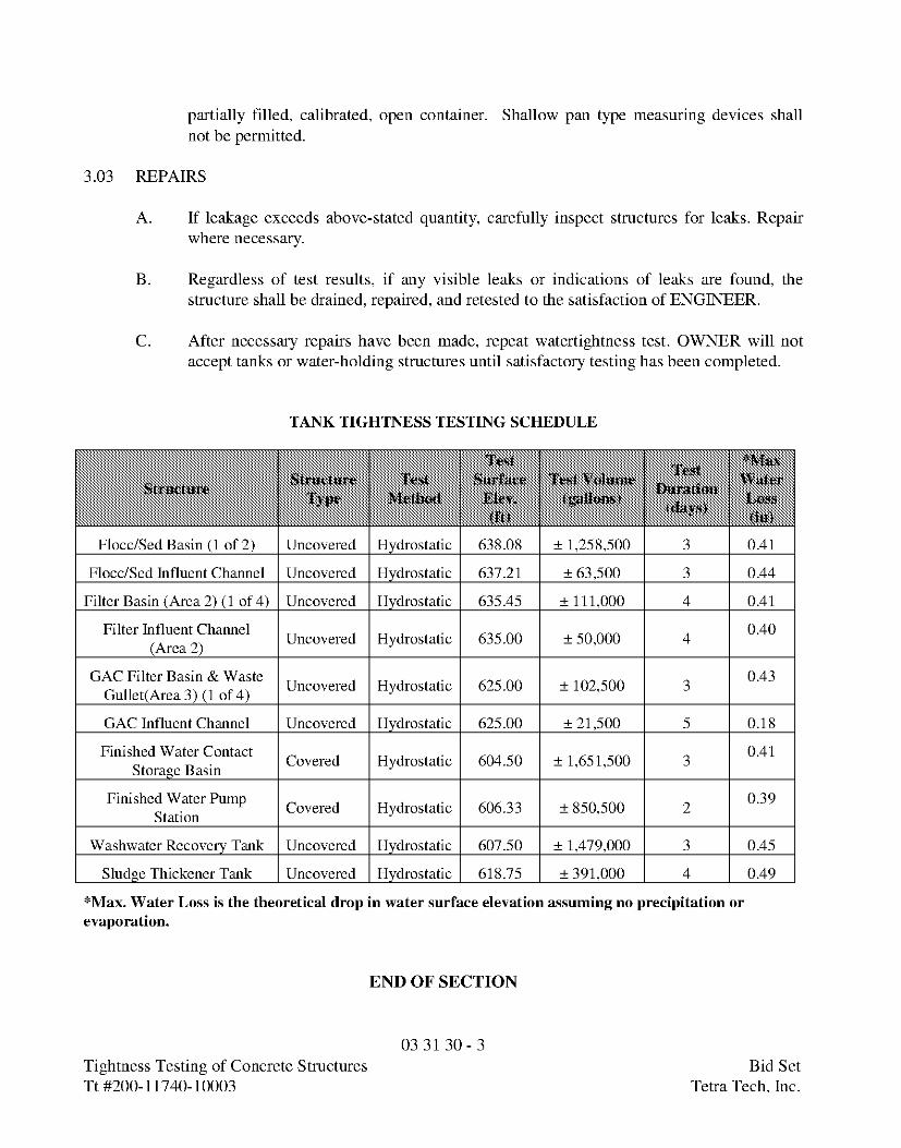
TANK TIGHTNESS TESTING SCHEDULE
Flocc/Sed Basin (1 of 2) Uncovered Hydrostatic 638.08 ± 1,258,500 3 0.41
Flocc/Sed Influent Channel Uncovered Hydrostatic 637.21 ± 63,500 3 0.44
Filter Basin (Area 2) (1 of 4) Uncovered Hydrostatic 635.45 ± 111,000 4 0.41
e Uncovered Hydrostatic 635.00 ± 50,000 4
GAC Filter Basin & Waste Uncovered Hydrostatic 625.00 ± 102,500 3Gullet(Area 3) (1 of 4)
GAC Influent Channel Uncovered Hydrostatic 625.00 ± 21,500 5 0.18
Finished Water Contact Covered Hydrostatic 604.50 ± 1,651,500 3Storage Basin
Finished Water Pump Covered Hydrostatic 606.33 ± 850,500 2Station
Washwater Recovery Tank Uncovered Hydrostatic 607.50 ± 1,479,000 3 0.45
Sludge Thickener Tank Uncovered Hydrostatic 618.75 ± 391,000 4 0.49
*Max. Water Loss is the theoretical drop in water surface elevation assuming no precipitation orevaporation.
END OF SECTION
03 31 30 - 3Tightness Testing of Concrete Structures Bid SetTt#200-11740-10003 Teka Tech,Inc.

SECTION 03 41 00STRUCTURAL PRECAST CONCRETE
PART 1 GENERAL
1.01 SUMMARY
A. Section Includes: Extent of structural precast concrete work as shown on Drawings.
B. Structural precast concrete includes the following:
1. Hollow core slab units.2. Tee type units.
C. Related Documents: Drawings and general provisions of Contract, including Generaland Supplementary Conditions and Division 1, apply to Work of this Section.
1.02 SUBMITTALS
A. Shop Drawings: Submit in accordance with Section 01 33 00, Submittal Procedurescovering the items included under this Section. Shop Drawing submittals shall include:
1. Submit manufacturer's specifications and instructions for manufactured materialsand products. Include manufacturer's certifications and laboratory test reports as
required.2. Submit Shop Drawings showing complete information for fabrication and
installation of precast concrete units. Indicate member dimensions and cross-section,location, size, and type of reinforcement including special reinforcement and liftingdevices necessary for handling and erection.
a. Indicate layout, dimensions, and identification of each precast unitcorresponding to sequence and procedure of installation. Indicate weldedconnections by AWS standard symbols. Detail inserts, connections, and jointsincluding accessories and construction at openings in precast units.
3. Include erection procedure for precast units and sequence of erection.
B. Concrete Compression Test Report: Submit written reports of Concrete CompressionTest results for approval prior to shipment, in accordance with Section 01 45 16.13,Contractor Quality Control.
03 41 00 - 1Structure Precast Concrete Bid SetTt#200-11740-10003 Teka Tech,Inc.
1.03 DESIGN REQUIREMENTS
A. Design by Fabricator: Design precast slab units to support superimposed dead loads andlive loads. The slab and tee section sizes provided on Drawings are based onapproximate uniform live and dead loads. Manufacturer shall design the units for actualuniform live and dead loads, equipment loads, and other concentrated loads shown onDrawings.
1. Design roof units for all applicable uniform live loads and dead loads as shownon Drawings.
2. Design floor units for the concentrated loads as shown, including equipmentloads and monorail loads.
3. On tee type units, provide a positive camber, under fully loaded condition, of notless than 1 inch per 40 feet of span.
1.04 QUALITY ASSURANCE
A. Codes and Standards: Comply with provisions of following codes, specifications, andstandards, except as otherwise indicated:
1. ACI 301, "Specifications for Structural Concrete for Buildings."2. ACI 318, "Building Code Requirements for Reinforced Concrete."3. Concrete Reinforcing Steel Institute, "Manual of Standard Practice."4. Prestressed Concrete Institute MNL 116, "Manual for Quality Control for Plants
and Production of Precast Concrete Products."
B. Fabricator Qualifications: Firms which have 2 years successful experience in fabricationof precast concrete units similar to units required for this Project will be acceptable.Fabricator must have sufficient production capacity to produce required units withoutcausing delay in Work.
1. Fabricator must be producer member of the Prestressed Concrete Institute (PCI)and/or participate in its Plant Certification Program.
2. Produce precast concrete units at fabricating plant engaged primarily inmanufacturing of similar units, unless plant fabrication or delivery to Site isimpractical.
3. If units are not produced at precast concrete fabricating plant, maintainprocedures and conditions for quality control which are equivalent to plantproduction.
4. Size Changes: Thicker units than those shown may be used. Supplier to informthe General Contractor of such change so additional material and Work requiredby other trade can be included in the Contract Price.
03 41 00 - 2Structure Precast Concrete Bid SetTt#200-11740-10003 Teka Tech,Inc.
1.05 DELIVERY, STORAGE, AND HANDLING
A. Deliver precast concrete units to Site in such quantities and at such times to assurecontinuity of installation. Store units at Site with care to prevent cracking, distortion,staining, or other physical damage, and so that markings are visible. Lift and supportunits at designated lift points. Use slings in handling; the use of chockers, chains, etc., isnot allowed.
B. Deliver anchorage items which are to be embedded in other construction before start ofsuch Work. Provide setting diagrams, templates, instructions, and directions as requiredfor installation.
PART 2 PRODUCTS
2.01 MANUFACTURERS
A. Subject to compliance with specified requirements, manufacturers offering productswhich may be incorporated in Work include:
1. Nonmetallic Shrinkage-Resistant Grout:
a. Euco N.S., Euclid Chemical Co.b. Crystex, L&M Construction Chemicals.c. Masterflow 713, Master Builders.d. Five Star Grout, U.S. Grout Corp.
2.02 FORMWORK
A. Provide forms and, where required, form-facing materials of metal, plastic, wood, orother acceptable material that is nonreactive with concrete and will produce requiredfinish surfaces.
B. Accurately construct forms mortar-tight, of sufficient strength to withstand pressuresdue to concrete placing operations, temperature changes, and prestressed, pretensioningand detensioning operations. Maintain formwork to provide completed precast concreteunits of shapes, lines, and dimensions indicated, within fabrication tolerances specifiedin PCI MNL 116.
C. Unless forms for plant manufactured prestressed concrete units are stripped prior todetensioning, design forms so that stresses are not induced in precast units due todeformation of concrete under prestress or to movement during detensioning.
03 41 00 - 3Structure Precast Concrete Bid SetTt#200-11740-10003 Teka Tech,Inc.
2.03 REINFORCING MATERIALS
A. Reinforcing Bars: ASTM A 615, Grade 60, unless otherwise indicated.
B. Low-Alloy Steel Reinforcing Bars: ASTM A 706.
C. Steel Wire: ASTM A 82, plain, cold-drawn, steel.
D. Welded Wire Fabric: ASTM A 185.
E. Welded Deformed Steel Wire Fabric: ASTM A 497.
F. Supports for Reinforcement: Provide supports for reinforcement including bolsters,chairs, spacers, and other devices for spacing, supporting, and fastening reinforcing,complying with CRSI recommendations.
1. For exposed-to-view concrete surfaces where legs of supports are in contact withforms, provide supports with legs which are plastic protected (CRSI, Class 1) orstainless steel protected (CRSI, Class 2).
2.04 PRESTRESSING TENDONS
A. Uncoated, 7-wire stress-relieved strand complying with ASTM A 416. Use Grade 250unless Grade 270 indicated.
2.05 CONCRETE MATERIALS
A. Portland Cement: ASTM C 150, Type I or Type III.
B. Use only one brand and type of cement throughout Project, unless otherwise acceptableto ENGINEER.
C. Aggregates: ASTM C 33. Provide aggregates from a single source for exposed concrete.
D. Water: Potable.
E. Air-Entraining Admixture: ASTM C 260.
F. Water-Reducing Admixture: ASTM C 494, Type A, or other type approved forfabricator's units. Admixtures containing calcium chloride are not permitted.
2.06 CONNECTION MATERIALS
A. Steel Plates: Structural quality, hot-rolled carbon steel, ASTM A 283, Grade C.
03 41 00 - 4Structure Precast Concrete Bid SetTt#200-11740-10003 Teka Tech,Inc.
B. Steel Shapes: ASTM A 36.
C. Anchor Bolts: ASTM A 307, low-carbon steel bolts, regular hexagon nuts, and carbonsteel washers.
D. High Strength Threaded Fasteners: Heavy hexagon structural bolts, heavy hexagonbolts, and hardened washers complying with ASTM A 324.
E. Finish of Steel Units: Exposed units galvanized per ASTM A 153; others painted withrust-inhibitive primer.
F. Bearing Pads: Provide bearing pads for precast concrete units as follows:
1. On Bearing Masonry Walls: Tempered hardboard pads, smooth both sides, 1/2-inch thick.
2. On Non-bearing Masonry Walls: Closed cell neoprene pads, ASTM D 1056 andC 509, SAE, Grade SC 41, SC 42, or SC 43.
G. Rigid Filler Board: Use rigid-type roof insulation board detailed at the perimeter of theroof slabs.
H. Ceiling Caulk: See Joint Sealer specified in Division 7.
I. Welding Electrodes: Comply with AWS standards.
J. Accessories: Provide clips, hangers, and other accessories required for installation ofProject units and for support of subsequent construction or finishes.
2.07 GROUT MATERIALS
A. Cement Grout: Portland cement, ASTM C 150, Type I, and clean, natural sand, ASTMC 404. Mix at ratio of 1 part cement to 3 parts sand, by volume, with minimum waterrequired for placement and hydration.
B. Nonmetallic Shrinkage-Resistant Grout: Where nonshrink grout is shown on Drawings,use pre-mixed, nonmetallic, noncorrosive, nonstaining product containing selected silicasands, Portland cement, shrinkage compensating agents, plasticizing and water-reducingagents, complying with CRD-C621, with the amount of water as recommended bymanufacturer.
2.08 PROPORTIONING AND DESIGN OF MIXES
A. Prepare design mixes for concrete required.
03 41 00 - 5Structure Precast Concrete Bid SetTt#200-11740-10003 Teka Tech,Inc.
B. Design mixes may be prepared by an independent testing facility or by qualified precastmanufacturing plant personnel at precast manufacturer's option.
C. Proportion mixes by either laboratory trail batch or field experience methods, usingmaterials to be employed on the Project for concrete required, complying with ACI 318.
1. Produce standard-weight concrete consisting of specified Portland cement,aggregates, admixtures, and water to produce the following properties:
a. Compressive Strength: 5,000 psi minimum at 28 days. Release strengthfor prestressed units: 3,500 psi.
2. Cure compression test cylinders using same methods as used for precast concretework.
D. Admixtures:
1. Use air-entraining admixture to obtain 4 to 6 percent entrainment in concrete,unless otherwise indicated.
2. Use water-reducing admixtures in strict compliance with manufacturer'sdirections. Admixtures to increase cement dispersion or provide increasedworkability for low-slump concrete may be used subject to ENGINEER'sacceptance.
3. Use amounts as recommended by admixture manufacturer for climaticconditions prevailing at time of placing. Adjust quantities of admixtures asrequired to maintain quality control.
2.09 FABRICATION
A. Fabricate precast concrete units complying with manufacturing and testing procedures,quality control recommendations, and dimensional tolerances of PCI MNL-116, and asspecified for types of units required.
B. Ready-Mix Concrete: Comply with requirements of ASTM C 94 and as hereinspecified.
C. Delete references for allowing additional water to be added to batch for material withinsufficient slump. Addition of water to batch will not be permitted.
D. During hot weather, or under conditions contributing to rapid setting of concrete, ashorter mixing time than specified in ASTM C 94 may be required.
1. When the air temperature is between 85 and 90 degrees F, reduce mixing anddelivery time from 1-1/2 hours to 75 minutes, and when air temperature is above90 degrees F, reduce mixing and delivery time to 60 minutes.
03 41 00 - 6Structure Precast Concrete Bid SetTt#200-11740-10003 Teka Tech,Inc.
E. Built-in Anchorages: Accurately position built-in anchorage devices and secure toformwork. Locate anchorages where they do not affect position of main reinforcementor placing of concrete. Do not relocate bearing plates in units unless acceptable toENGINEER.
F. Cast-in holes for openings larger than 10-inch diameter or 10-inch square in accordancewith final Shop Drawings. Other smaller holes will be field cut by trades requiringthem, as acceptable to ENGINEER.
G. Coat surfaces of forms with bond-breaking compound before reinforcement is placed.Provide commercial formulation form-coating compounds that will not bond with, stain,or adversely affect concrete surfaces, and will not impair subsequent treatments ofconcrete surfaces requiring bond or adhesion. Apply in compliance with manufacturer'sinstructions.
H. Clean reinforcement of loose rust and mill scale, earth, and other materials which reduceor destroy bond with concrete.
I. Accurately position support and secure reinforcement against displacement byformwork construction or concrete placement operations. Locate and supportreinforcing by metal chairs, runners, bolsters, spacers, and hangers as required.
J. Place reinforcement to obtain at least the minimum coverages for concrete protection.Arrange, space, and securely tie bars and bar supports to hold reinforcement in positionduring concrete placement operations. Set wire ties so ends are directed into concrete,not toward exposed concrete surfaces.
K. Pretensioning of tendons for prestressed concrete may be accomplished either by single-strand tensioning method or multiple-strand tensioning method. Comply with PCIMNL-116 requirements.
L. Place concrete in a continuous operation to prevent formation of seams or planes ofweakness in precast units, complying with requirements of ACI 304. Thoroughlyconsolidate placed concrete by internal and external vibration without dislocation ordamage to reinforcement and built-in items.
M. Provide permanent markings to identify pick-up points and orientation in structure,complying with markings indicated on final Shop Drawings. Imprint date of casting oneach precast unit on a surface which will not show in finished structure.
N. Curing by low-pressure steam, steam vapor, radiant heat and moisture, or other similarprocess may be employed to accelerate concrete hardening and to reduce curing time.
03 41 00 - 7Structure Precast Concrete Bid SetTt#200-11740-10003 Teka Tech,Inc.
O. Delay detensioning of prestressed units until concrete has attained at least 70 percent ofdesign stress, as established by test cylinders.
P. If concrete has been heat-cured, perform detensioning while concrete is still warm andmoist, to avoid dimensional changes which may cause cracking or undesirable stressesin concrete.
Q. Detensioning of pretensioned tendons may be accomplished either by gradual release oftensioning jacks or by heat cutting tendons, using a sequence and pattern to preventshock or unbalanced loading.
R. Finish of Formed Surfaces: Provide finishes for formed surfaces of precast concreteunits as follows:
1. Commercial Finish: Remove fins and large protrusions and fill holes. Rub orgrind ragged edges. Faces to be true, well-defined surfaces.
S. Finish of Unformed Surfaces: Apply trowel finish to unformed surfaces unlessotherwise indicated. Consolidate concrete; bring to proper level with a straightedge,float, and trowel to a smooth, uniform finish.
1. Apply scratch finish to precast units which will receive concrete topping afterinstallation. Following initial strike-off, transversely scarify surface to provideridges approximately 1/4-inch deep.
2.10 HOLLOW CORE SLAB UNITS
A. Precast, prestressed concrete units with open voids running full length of slabs.
B. Furnish units which are free of voids or honeycomb with straight true edges andsurfaces.
C. Provide "Commercial Finish" units unless otherwise indicated.
D. Manufacturer units of concrete materials which will provide a minimum 3,500 psicompressive strength at time of initial prestress and a 28-day compressive strength of5,000 psi.
E. Adequately reinforce slab units to resist transporting and handling stresses.
F. Include cast-in weld plates where required for anchorage or lateral bracing to structuralsteel members.
G. Coordinate with other trades for installation of items to be cast-in units.
03 41 00 - 8Structure Precast Concrete Bid SetTt#200-11740-10003 Teka Tech,Inc.
H. Provide headers of cast-in-place concrete or structural steel shapes for openings largerthan 1/2 slab width in accordance with hollow slab unit manufacturer's
recommendations.
I. Standard Details are included on Drawings.
2.11 TEE TYPE UNITS
A. Type: Plant fabricated, precast, prestressed concrete units produced under rigid, factoryinspected process.
B. Furnish units which are free of voids or honeycomb with straight true edges andsurfaces.
C. Provide "Commercial Finish" units as specified.
D. Where ends of strands will not be enclosed or covered, cut flush and cover with high-strength mortar bonded to unit with epoxy resin bonding agent.
E. Where used as floor or roof members with composite topping, provide broomed orraked top finish for bonding with concrete floor topping.
F. Where used as roof members without composite topping, provide smooth, float topfinish.
G. Adequately reinforce units to resist transporting and handling stresses.
H. Provide cast-in weld plates where required for anchorage or lateral bracing to structuralsteel and adjacent precast members. Weld flanges of all units together at 10-foot spacingor at quarter points of span, whichever is less.
I. Coordinate with other trades for installation of items to be cast in units.
J. Provide block-outs for openings in accordance with design Drawings or precast unitmanufacturer's recommendations.
2.12 SOURCE QUALITY CONTROL
A. Dimensional Tolerances: Units having dimensions smaller or greater than required, andfall outside of specified tolerance limits, will be subject to additional conditions asherein specified.
1. Precast units having dimensions greater than required will be rejected ifappearance or function of the structure is adversely affected, or if larger
03 41 00 - 9Structure Precast Concrete Bid SetTt#200-11740-10003 Teka Tech,Inc.
dimensions interfere with other construction. Repair, or remove and replacerejected units as required to meet construction conditions.
B. Strength of Units: The strength of precast concrete units will be considered potentiallydeficient if the manufacturing processes fail to comply with any of the requirementswhich may affect the strength of the precast units, including the following conditions:
1. Failure to meet compressive strength tests requirements.2. Reinforcement, and pretensioning and detensioning of tendons of prestressed
concrete, not conforming to specified fabrication requirements.3. Concrete curing, and protection of precast units against extremes in temperature,
not as specified.4. Precast units damaged during handling and erection.
C. Testing Precast Units: When there is a question that strength of precast concrete unitsmay not meet specification requirements, CONTRACTOR shall engage a testinglaboratory at its expense to take cores drilled from hardened concrete for compressivestrength determination, complying with ASTM C 42 and as follows:
1. Take at least 3 representative cores from precast units of suspect strength fromlocations directed by ENGINEER.
2. Test cores in a saturated-surface-dry condition per ACI 318 if concrete will bewet during use of completed structure.
3. Test cores in an air-dry condition per ACI 318 if concrete will be dry during useof completed structure.
4. Strength of concrete for each series of cores will be considered satisfactory iftheir average compressive strength is at least 85 percent of 28-day designcompressive strength.
5. Tests results shall be made in writing within 2 days of tests, with copies toENGINEER, CONTRACTOR, and precast manufacturer. Include in test reportsthe Project identification name and number, date, name of precast concretemanufacturer, name of concrete testing service, identification letter, number, andtype of member or members represented by core tests, design compressivestrength, compression breaking strength and type of break (corrected for length-diameter ratio), direction of applied load to core with respect to horizontal planof concrete as placed, and moisture condition of core at time of bearing.
D. Patching: Where core test results are satisfactory and precast units are acceptable for usein Work, fill core holes solid with patching mortar and finish to match adjacent concretesurfaces.
E. Defective Work: Precast concrete units which do not conform to specified requirements,including strength, tolerances, and finishes, shall be replaced with precast concrete unitsthat meet requirements of this Section. CONTRACTOR shall also be responsible for
03 41 00 - 10Structure Precast Concrete Bid SetTt#200-11740-10003 Teka Tech,Inc.
cost of corrections to other Work affected by or resulting from corrections to precastconcrete work.
PART 3 EXECUTION
3.01 INSTALLATION
A. Temporary Shoring and Bracing: Provide temporary shoring and bracing members withconnections of sufficient strength to bear imposed loads. Remove temporary membersand connections when permanent members are in place and final connections are made.
B. Bearing Pads: Install flexible bearing pads where indicated as precast units are beingerected. Set pads on level, uniform bearing surfaces, held back 1/2 inch for caulking,and maintain in correct position until precast units are placed.
C. Welding: Perform welding in compliance with AWS D 1.1, including qualification ofwelders.
1. Protect units from damage by field welding or cutting operations and providenoncombustible shield as required.
2. Repair damaged metal surfaces by cleaning and applying a coat of liquidgalvanizing repair compound to galvanized surfaces and compatible primer topainted surfaces.
D. Powder-Actuated Fasteners: Do not use powder-actuated fasteners for surfaceattachment of accessory items in precast, prestressed unit unless otherwise accepted byprecast manufacturer.
E. Erection Tolerances: Install precast units without exceeding tolerance limits specified inPCI MNL-127, "Recommended Practice for Erection of Precast Concrete."
F. Grouting Connections and Joints: After precast concrete units have been placed andsecured, grout open spaces at connection and joints.
1. Where the top surface elevation of adjacent units varies more than 1/2 inch,place cement grout fillet on the low side to provide for a gradual transitionbetween units.
2. Fill cores at roof openings and exposed ends with concrete grout for a length of4 inches. Provide finish on exposed grouted surfaces matching that of adjacentsurfaces.
3. Provide forms or other acceptable method to retain grout in place untilsufficiently hard to support itself. Pack spaces with stiff grout material, tampinguntil voids are completely filled. Place grout to finish smooth, plumb, and levelwith adjacent concrete surfaces. Keep grouted joints damp for not less than 24
03 41 00 - 11Structure Precast Concrete Bid SetTt#200-11740-10003 Teka Tech,Inc.
hours after initial set. Promptly remove grout material from exposed surfacesbefore it hardens.
4. Caulk all joints that will be exposed to view on bottom of flat units and onbottom of flanges of tee-type units, including joints between the flat units andmasonry walls adjoining or supporting the slabs.
END OF SECTION
03 41 00 - 12Structure Precast Concrete Bid SetTt#200-11740-10003 Teka Tech,Inc.