Embed Size (px)
Citation preview
03-01-1 Enaine. 1.6L 03-01-1
SECTION 03-0 1 Engine, l.6L
SUBJECT PAGE
DESCRIPTION .................................................. 0 3 - 1 - 1 DISASSEMBLY AND ASSEMBLY
Assembly ............................................................ 03-01-32 Flywheel, Pilot Bearing ..................................... 03-01-33 Oil Pump .............................. .. .......................... 03-01-32
Cylinder Head ...................................................... 03-01-29 Engine ......................................................... 03-01-22
................ ...................... Subassemblies ....... 03-01-31 Piston andconnecting Rod .............................. 03-01-31
REMOVAL AND INSTALLATION Camshaft ........................................................... 03-01-13 Camshaft Seal ................... .... ................. 03-01-16 Core Plugs ........................................................... 03-01-22 Crankshaft Oil Seal, Front .................................... 03-01-21 Crankshaft Oil Seal, Rear ..................................... 03-01-21 Crankshaft, Main Bearings and Connecting
Rod Bearings .................................................. 03-01-15 Cylinder Head ................................................. ......OOl-9 Engine Assembly ................................................. 03-01-2 Exhaust Manilold ..................................... ... .... 03-01-17 Intake Manifold ........... .... ................................ 03-01-16 Oil Pan ............................................................... 03-01-18 Oil Pump ................... .. ................................... 03-01-20 Piston and Connecting Rod Assembly .................. 03-01-20 Thermostat .......................................................... 03-01-18 Throttle Body ...................................................... 03-01-18 Timing Belt .......................................................... 0 0 1 1 1
SUBJECT PAGE
REMOVAL AND INSTALLATION (Cont'd.) Valvestem Seals ................................................. 03-01-18 Water Pump ......................................................... 03-01-16
SERVICE PROCEDURES Camshalt ............................................................. 03-01-43 Connecting Rod ................................................... 03-01-37 Crankshaft .......................................................... 03-01-37 Crankshaft and Connecting Rod
Bearings .......................................................... 03-01-38 Crankshaft End Play .................... .. .................... 03-01-39 Crankshaft Oil Clearance ................................... 03-01-39 ~- ~ - -
Cylinder Block ..................................................... 03-01-33 Cylinder Block Flatness ..................................... 03-01-34 Cylinder Bores ..................................................... 03-01-35 Cylinder Head ...................................................... 03-01-40
Cylinder Head Flatness ..................................... 03-01-41 Valve and Valve Guide ....................................... 03-01-41 Valve Seat ........................................................ 3 1 - 4 2 Valve S ~ r i n a ................... ... ............................ 03-01-43 . -
Oil Jet .................................................................. 03-01-40 Oil Pump ............................. ........... ................. 03-01-39 Pistons, Piston Rings and Piston Pins ................... 03-01-36 Service Limit Specifications ............................... 03-01-33
SPECIAL SERVICE TOOLS ....................................... 03-01-48 SPECIFICATIONS .................................................... 03-01-46 VEHICLE APPLICATION ............................................. 03-01-1
I VEHICLE APPLICATION I Capri
DESCRIPTION
The 1.6L naturally aspirated and 1.6L Turbocharged 1 Intercooled engines are double overhead cam (DOHC), four valves per cylinder, four cylinder engines. The cylinder head is aluminum and incorporates directly operating bucket-type hydraulic lash adjusters (HLA).
The camshafts are driven by a single, toothed belt. One camshaft oDerates the intake valves, one operates the exhaust valves The tlm ng belt 1s a~tomat~cal ly aal-sled by a spr ng tens~oned pulley
The intake manifold is aluminum and has a coolant passage for better driveability during cold weather o~erat ion.
The ignition system is an electronic, high output type using a vacuum advance distributor. The distributor is driven directly off the intake camshaft.
The multiport fuel injection (MFI) system is electronic. A volume air flow (VAF) (1 28529) meter senses intake air flow rate and temperature. An electric fuel pump, mounted inside the fuel tank delivers fuel at a constant rate to the fuel pressure regulator. The pressure regulator returns excess fuel to the fuel tank while keeping the four fuel injectors supplied with sufficient fuel through the fuel rail assembly.
lniector "on time" is controlled bv the Dowertrain control module (PCM) (12~650) ; based on information supplied by the VAF, engine coolant temperature (ECT) (12A648) sensor, and throttle position (TP) (9P989) sensor
I 1993Capii July. 19s
03-01-2 Enaine. 1.6L 03-01-2
DESCRIPTION (Continued)
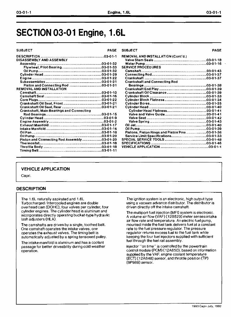
The lubrication system is a high pressure-type supplied by the oil pump. The oil pump is driven directly by the crankshaft. On turbocharged engines, oil spray nozzles are mounted in the cylinder block. The nozzles spray oil up into the ins~de of lhe pistons to aid in cooling and prevent detonation.
REMOVAL AND INSTALLATION
Engine Assembly Removal I I 2. Start lhe engineand allow it lo run until il stalls.
The fuel pressure is now relieved. ~.
1. Relieve fuel pressure by disconnecting electrical I I 3. Discharge the air conditioning system, if
connector at fuel pump-sending unit assembly equipped. Refer to Section 12-00.
located under rear seat cushion. Mnecessary, refer to Section 01-10 for rear seat cushion I I removal
-
- 1993Capri July, 1992
03-01-3 Engine, l.6L 03-01-3
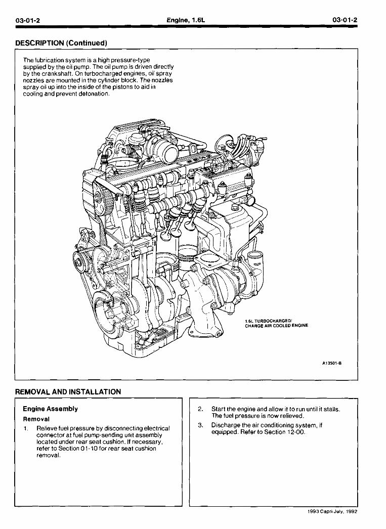
4. Disconnect and remove battery, battery tray and battery tray support bracket.
, - BATTERY TRhY SUPPORT BRACKET nA705
5. Release wiring harness retaining straps from battery support tray.
6. Disconnect windshield washer supply hose between washer fluid reservoir and hood.
7. Mark hood hinge locations and remove hood.
8. Disconnect intake air tube and wiring to ignition coil and volume air flow meter.
9. Remove air cleanerlvolume air flow meter assembly. Refer to Section 03-12.
10. Remove air cleaner assembly support brackets. Refer to Section 03- 12.
11. Disconnect charge air cooler hoses from turbocharger, if equipped.
12. Drain engine coolant and remove radiator. Refer to Section 03-03.
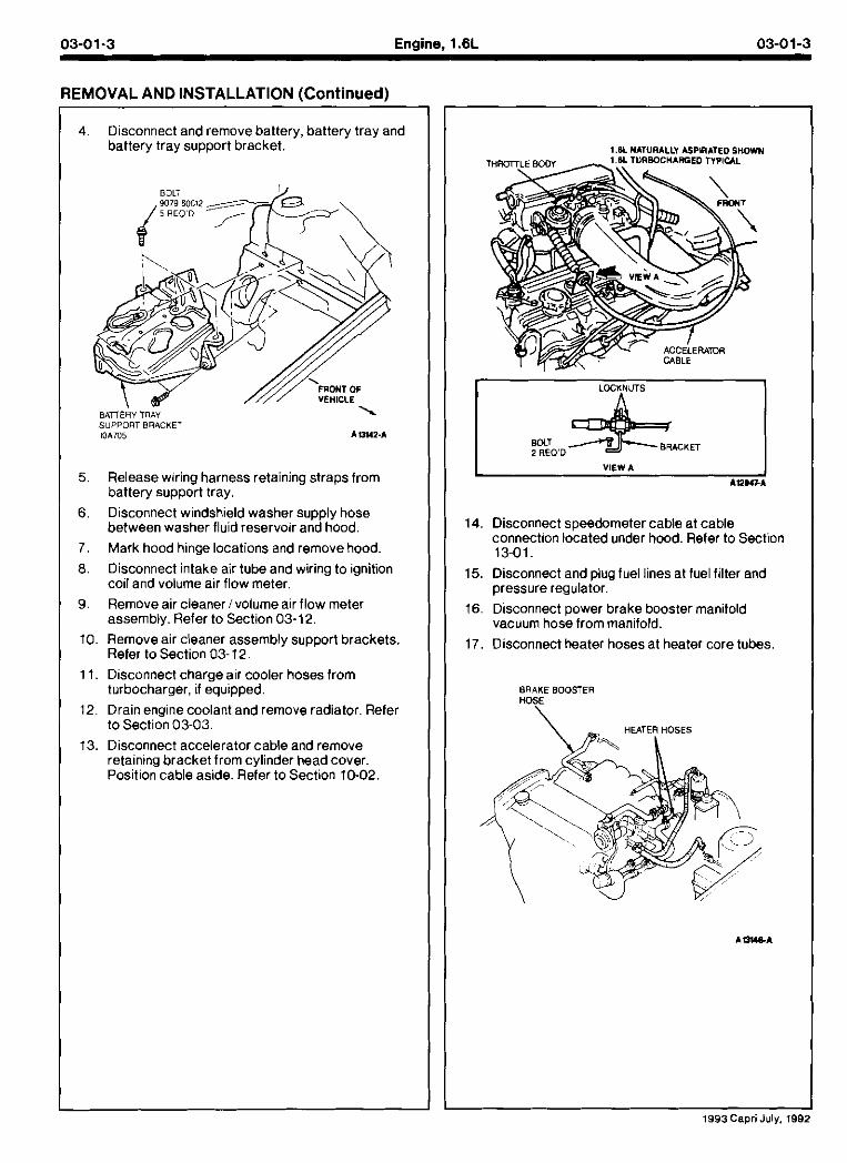
13. Disconnect accelerator cable and remove retaining bracket from cylinder head cover. Position cable aside. Refer to Section 10-02
1 . L NATURALLY ASPlRATED SHOWN HAFGED TYPICAL
L VIEW A 1 A n n F A
14. Disconnect speedometer cable at cable connection located under hood. Refer to Section 13-01.
15. Disconnect and plug fuel lines at fuel filter and pressure regulator.
16. Disconnect power brake booster manifold vacuum hose from manifold.
17. Disconnect heater hoses at heater core tubes.
BRAKE BOOSTER HOSE
\
1993Capri July. 188:
03-01-4 Enalne. 1.6L 03-01-4
EMOVAL AND INSTALLATION (Continued)
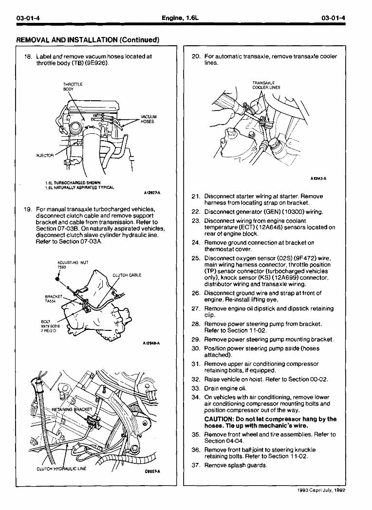
18. Label and remove vacuum hoses located at throttle body (TB) (9E926).
1.61 TURBOCHARGEDSHOWN 1.6L NATURALLY ASPIRATED TYPICAL
AlZSZFA
19. For manual transaxle turbocharged vehicles, disconnect clutch cable and remove sumort bracket and cable from transmission. defer to Sect~on 07.038 On naturally asparated vehcles. disconnect clutch slave cylinder'hydraulic line. Refer to Section 07-03A.
ADJUSTING NUT 7593
20. For automatic transaxle, remove transaxle cooler lines.
T R A N W L E , COOLER LINES
21. Disconnect starter wiring at starter. Remove harness from locating strap on bracket.
22. Disconnect generator (GEN) (10300) wiring.
23. Disconnect wiring from engine coolant temperature (ECT) (12A648) sensors located on rear of engine block.
24. Remove ground connection at bracket on thermostat cover.
25. Disconnect oxygen sensor (02s) (9F472) wire, main wiring harness connector, throttle position (TP) sensor connector (turbocharged vehicles only), knock sensor (KS) (12A699)connector. distributor wiring and transaxle wiring.
26. Disconnect ground wire and strap at front of engine. Re-install lifting eye.
27. Remove engine oil dipstick and dipstick retaining clip.
28. Remove power steering pump from bracket. Refer to Section 11-02.
29. Remove power steering pump mounting bracket.
30. Position power steering pump aside (hoses attached).
31. Remove upper air conditioning compressor retaining bolts, if equipped.
32. Raise vehicle on hoist. Refer to Section 00-02. 33. Drain engine oil.
34. On vehicles with air conditioning, remove lower air conditioning compressor mounting bolts and position compressor out of the way. CAUTION: Do not let compressor hang by the hoses. Tie up with mechanic's wire.
35. Remove front wheel and tire assemblies. Refer to Section 04-04.
36. Remove front ball joint to steering knuckle retaining bolts. Refer to Section 11-02.
37. Removesplash guards.
1993Capri July. 108
03-01-5 Englne, 1.6L 03-01-5
REMOVAL AND INSTALLATION (Continued)
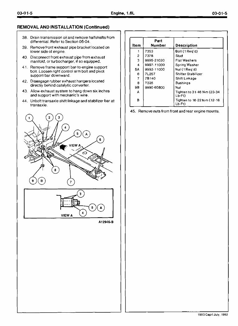
38. Drain transmission oil and remove halfshaftsfrom differential. Refer to Section 05-04.
39. Removefront exhaust pipe bracket located on lower side of engine.
40. Disconnect front exhaust pipe from exhaust manifold, or turbocharger, if so equipped.
4 1. Remove frame support bar-to-engine support bolt. Loosen right control arm bolt and pivot support bar downward.
42. Disengage rubber exhaust hangers iocated directly behind catalytic converter.
43. Allow exhaust system to hang down six inches and support with mechanic's wire.
44. Unbolt transaxle shift linkage and stabilizer bar at transaxle.
-1 VIEW A
Part Number Y-k - Bolt (1 Req'd)
Stud Flat Washers Spring Washer Nut (1 Req'd) Shitter Stabilizer Shift Linkage Bushings Nut Tighten to 31.46 Nm (23-34 Lb-Ft) Tighten to 16-22N.m (12-16
45. Remove nuts from front and rear engine mounts
1993Cepri July, 1992
03-01-6 Engine, 1.6L 03-01-6
REMOVAL AND INSTALLATION (Continued)
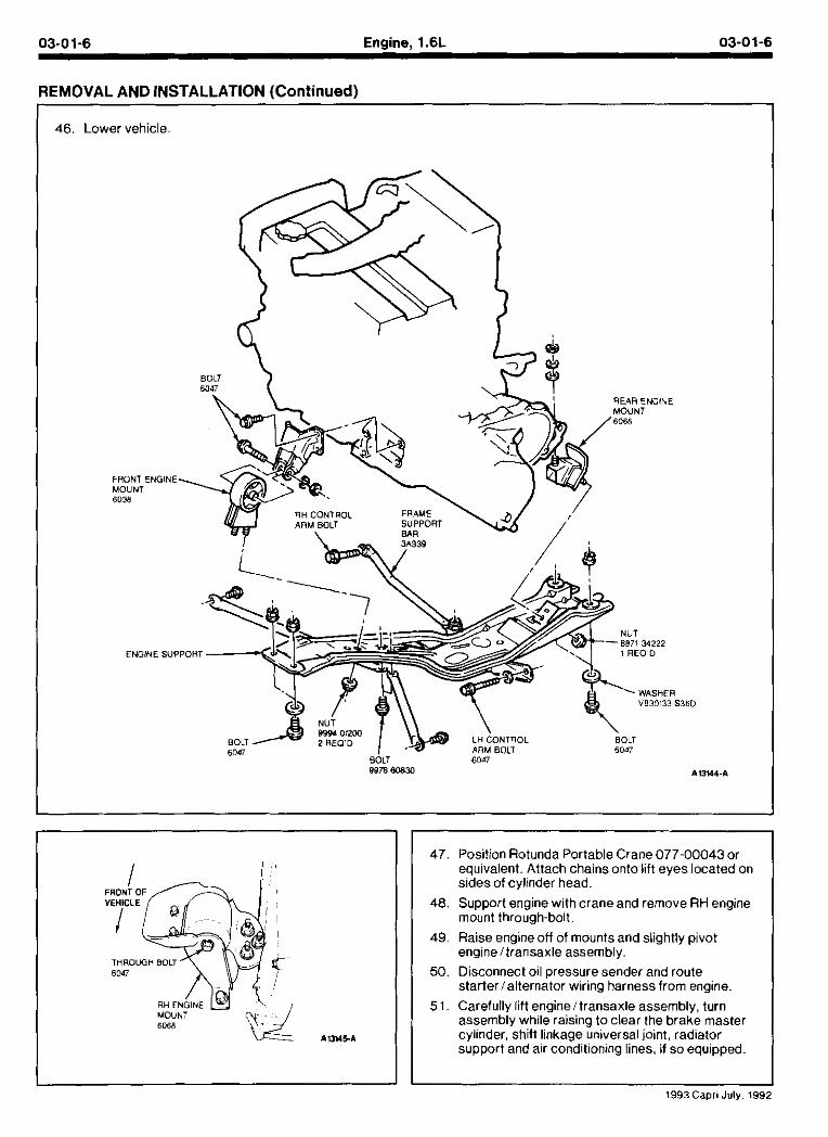
46. Lower vehicle.
REAR ENGINE
FRONT ENGINE MOUNT 6038
-6B7l 34222 ENGINE SUPPORT
V830133S36D
LH ONTROL BOLT 6017 6047
BOLT 6047 WrS earn A l N 1 - A
MOUNT
47. Position Rotunda Portable Crane 077-00043 or equivalent. Attach chains onto lift eyes located on sides of cylinder head.
48. Support engine with crane and remove RH engine mount through-bolt.
49. Raise engine off of mounts and slightly pivot engineltransaxle assembly.
50. Disconnect oil pressure sender and route starterlalternator wiring harness from engine.
5 1. Carefully lift engineltransaxle assembly, turn assembly while raising to clear the brake master cylinder, shift linkage universal joint, radiator support and air conditioning lines, if so equipped.
03-01-7 Engine, 1.6L 03-01-7
REMOVAL AND INSTALLATION (Continued)
52. Remove intake manifold support bracket.
53. Remove gusset plate(s), if equipped. 54. Removestarter.
55. Remove transaxle to engine retaining bolts. Identify bolts to ensure they are installed in their correct locations for installation.
56. Separate transaxle from engine.
57. On manual transaxles, remove pressure plate, clutch disc, and flywheel.
58. On automatic transaxles, remove flywheel.
59. lnstall engineon engine stand.
Installation
1. Removeengine from stand. 2. lnstall end plate. lighten retaining screw to 8-1 1
N.m (7 1-97 lb-in).
3. For manual transaxle, install the following:
a. lnstall flywheel. Apply Threadlock and Sealer EOAZ-19554-AA (ESE-M4G204-A) or equivalent to flywheel bolts. lighten retaining bolts to 96-103 N.m (7 1-76 Ib-ft).
b. Position clutch disc using Clutch Aligner T74P-7 137-K or equivalent.
c. lnstall pressure plate. lighten retaining bolts to 16-26 N.m (14-19 Ib-ft).
4. For automatic transaxle, install flywheel. Tghten retaining bolts to 96-103 N.m (7 1-76 Ib-ft).
5, lnstall intermediate axle shaft and bearing, if equipped. lighten bearing mount retaining bolts to 37-52 N m (28-38 Ib-ft).
6. For manual transaxle, install as follows:
a. Position transaxle toengine and install retaining bolts.
b. lighten bolts " A to 89-1 17 N m (66-86 Ib-It).
c. Tghten bolts "6" to 37-52 N m (29-38 Ib-ft). 7. For automatic transaxle, install as follows:
a. Position transaxle to engine and install retaining bolts.
b. lighten bolts " A to 55-80 N m (41-59 Ib-ft).
c. Align torque converter and flywheel. lnstall retaining bolts, tighten to 34-49 N m (25-36 Ib-ft).
d. lnstall cover plate. lighten retaining bolts "B", to 7-10 N m (62-88 Ib-in).
e. lnstall gusset platecs), if removed. Tghten retaining bolts on engine to 37-52 N m (28-38 Ib-ft). lighten bolts to transaxle to 55-80 N m (41-59 lb-ft).
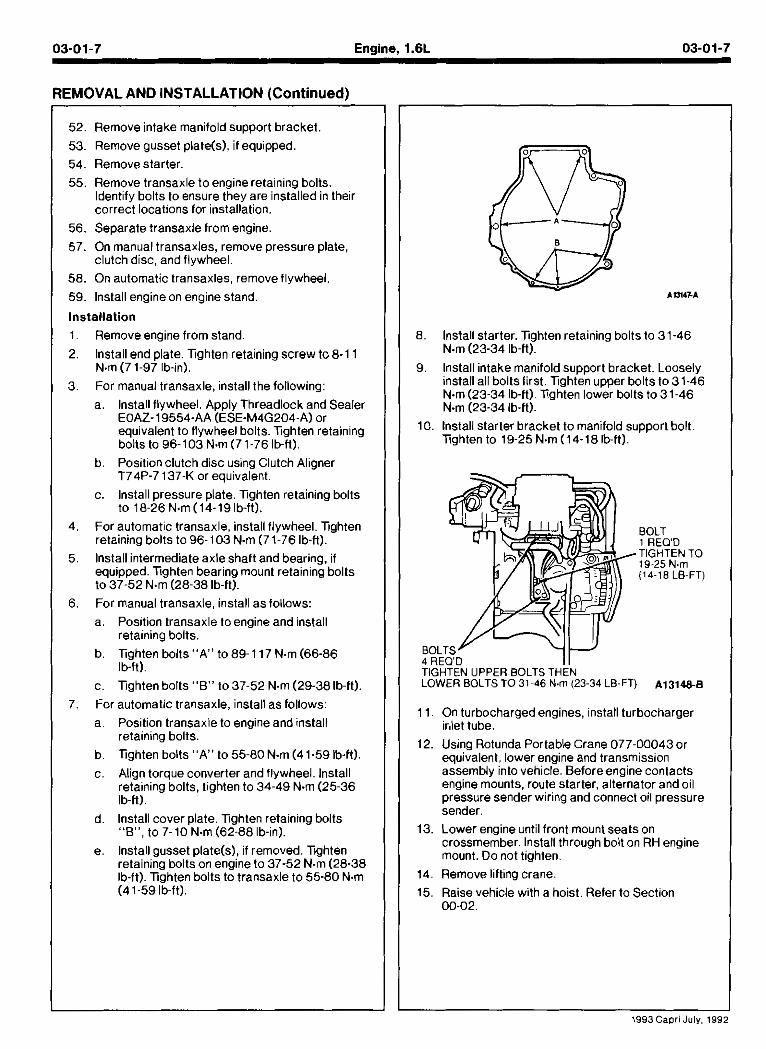
lnstall starter. lighten retaining bolts to 31-46 N m (23-34 Ib-ft).
lnstall intake manifold support bracket. Loosely install all bolts first. lighten upper bolts to 31-46 N.m(23-34 lb-ft). lighten lower bolts to 31-46 N m (23-34 Ib-ft).
lnstall starter bracket to manifold support bolt. lighten to 19-25 N.m(I4-18Ibft).
11. On turbocharged engines, install turbocharger irJet tube.
12. Using Rotunda Portable Crane 077-00043 or equivalent. lower engine and transmission assembly into vehicle. Beforeengine contacts engine mounts, route starter, alternator and oil pressure sender wiring and connect oil pressure sender.
13. Lower engine .nt I front mount seats on crossmember lnstall throuqn bod on RH enqine . . mount. Do not tighten.
14. Remove lifting crane.
15. Raise vehicle with a hoist. Refer to Section 00-02.
-
- 1993 Capri July, 1992
03-01-8 Engine, l.6L 03-0 1-8
REMOVAL AND INSTALLATION (Continued)
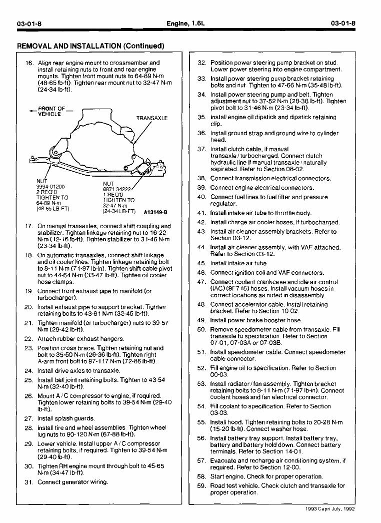
16. Align rear engine mount to crossmember and install retaining nuts to front and rear engine mounts. Tighten front mount nuts to 64-89 N m (48-65 lb-ft). Xghten rear mount nut to 32-47 N.m (24-34 Ib-ft).
64-89 N m TIGHTEN TO
(48~65 LB-FT) 32-47 N m (24-34 LB-FT) A131498
17 On manual transaxles connect snltt coupllng and stabuizer. Xahten I nkaoe relamina n,t to 16-22 N m (12- 16 ib-ft). Xghten stabilizer to 31-46 N.m (23-34 lb-ft).
18. On automatic transaxles, connect shift linkage and oil cooler lines. Tghten linkage retaining bolt to 8-1 1 N.m (71-97 lb-in). Tighten shift cable pivot nut to 44-64 N.m (33-47 lb-ft). Tghten oil cooler hose clamps.
19. Connect front exhaust pipe to manifold (or turbocharger).
20. lnstall exhaust pipe to support bracket. Tghten retaining bolts to 43-61 N.m (32-45 lb-ft).
21. Tighten manifold (or turbocharger) nuts to 39-57 N.m (29-42 lb-fi).
22. Attach rubber exhaust hangers.
23. Post or cross orace Tgrten reta nlng nut and oolt to 35-50 N.m (26-36 lb-H). Xghten rfgnt A.armfront bolt to 97-1 17 N m (72-86 Ib-ft).
24. lnstall drive axles to transaxle.
25. lnstall ball joint retaining bolts. Tghten to 43-54 N.m (32-40 lb-fi).
26. Mount AIC compressor to engine, if required. Tghten lower retaining bolts to 39-54 N.m (29-40 Ib-fi).
27. lnstall splash guards.
28. Install tire and wheel assemblies. Tghten wheel lug nuts to 90-120 N.m (67-88 lb-ft).
29. Lower vehicle, Install upper AIC compressor retaining boils, if required. Tghten to 39-54 N.m (29-40 1b-H).
30. Tghten RH engine mount through bolt to 45-65 N.m (34-47 lb-ft).
31. Connect generator wiring.
32 Posltlon power steer ng p-mp oracket on stud Lower power steerlng nto englne compartment
50. Removespeedometer cable from transaxle. Fill transaxle to soecification. Refer to Section 07-01.07-03k or 07-036.
51. Install speedometer cable. Connect speedometer cable connector.
52. Fill engine oil to specification. Refer to Section 00-03.
53. lnstall radiatorlfan assembly. Tighten bracket retaining bolts to 8-1 1 N m (71-97 Ib-in). Connect coolant hoses and fan electrical connector.
54. Fill coolant to specification. Refer to Section 03-03.
55. lnstall hood. Tghten retaining bolts to 20-28 N.m (15-20 lb-ft). Connect washer hose.
56. Install battery tray support. Install battery tray, battery and battery hold down. Connect battery terminals. Refer to Section 14-01
57. Evacuate and recharge air conditioning system, if required. Refer to Section 12-00.
58. Start engine. Check for proper operation.
59. Road test vehicle. Check clutch and transaxle for proper operation.
33. lnstall power steering pump bracket retaining bolts and nut. Tighten to 47-66 N m (35-48 Ib-ft).
34. lnstall power steering pump and belt. Xghten adjustment nut to 37-52 N m (28-38 Ib-fi). Tghten pivot bolt to 31-46 N m (23-34 Ib-ft).
35. lnstall engine oil dipstick and dipstick retaining clip.
36. lnstall ground strap and ground wire to cylinder head.
37. lnstall clutch cable, if manual transaxlelturbocharged. Connect clutch hydraulic line if manual transaxlei naturally aspirated. Refer to Section 08-02.
38. Connect transmission electrical connectors.
39. Connect engine electrical connectors.
40. Connect fuel lines to fuel filter and pressure regulator.
41. lnstall intake air tube to throttle body.
42. lnstall charge air cooler hoses, if turbocharged.
43. lnstall air cleaner assembly brackets. Refer to Section 03-12.
44. lnstall air cleaner assembly, with VAF attached. Refer to Section 03-12.
45. lnstall intake air tube.
46. Connect ignition coil and VAF connectors.
47. Connect coolant crankcase and idle air control (IAC) (9F7 15) hoses. lnstall vacuum hoses in correct locations as noted in disassembly.
48. Connect accelerator cable. Install retaining bracket. Refer toSection 10-02.
49. lnstall power brake booster hose.
-
- 1993Capr8 July, 1992
03-01 -9 Enalne. 1.6L 03-01-8
REMOVAL AND INSTALLATION IContinued)
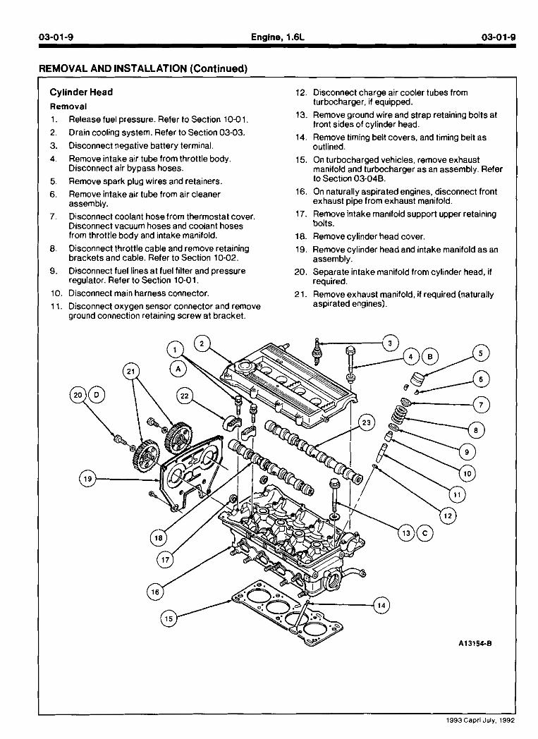
Cylinder Head Removal 1. Release fuel pressure. Reler to Section 10-01.
2. Drain cooling system. Refer to Section 03-03.
3. Disconnect negative battery terminal. 4. Remove intake air tube from throttle body.
Disconnect air bypass hoses.
5. Remove spark plug wires and retainers.
6. Remove intake air tube from air cleaner assembly.
7. Disconnect coolant hose from thermostat cover. Disconnect vacuum hoses and coolant hoses from throttle body and intake manifold.
8. Disconnect throttle cable and remove retaining brackets and cable. Refer to Section 10-02.
9. Disconnect fuel linesat fuel filter and pressure regulator. Refer to Section 10-01
10. Disconnect main harness connector.
1 Disconnect oxygen sensor connector and remove ground connection retaining screw at bracket.
12. Disconnect charge air cooler tubes from turbocharger, if equipped.
13. Remove ground wire and strap retaining bolts at front sides of cylinder head.
14. Remove timing belt covers, and timing belt as outlined.
15. On turbocharged vehicles, remove exhaust manilold and turbocharger as an assembly. Refer to Section 03-04B.
16. On naturally aspirated engines, disconnect front exhaust pipe from exhaust manifold.
17. Remove intake manifold support upper retaining bolts.
18. Remove cylinder head cover.
19. Remove cylinder headand intake manifold as an assembly.
20. Separate intake manifold from cylinder head, if required.
21. Remove exhaust manifold, if required (naturally aspirated engines).
03-01-10 Enalne. 1.6L 03-01-10
REMOVAL AND INSTALLATION (Continued)
--
I 4R I &548 I Bolt IBReo'd l I 16 1 6250 1 ExhaustCamshalt 1
Item
1A
2
3
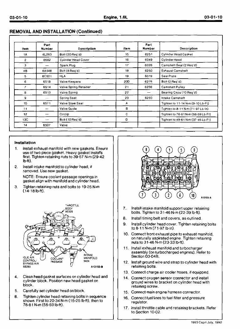
Installation
lnstall exhaust manifold with new gaskets. Ensure
. -.. Number
6L293
6562
-
use of two plece gasket. Heavy gasket installs first. lighten retaining nJts to 39-57 N.m (29-42 . Ib-ft).
lnstall intake manifold to cylinder head, if removed. Use new gasket.
Deacrl~tlon
Boll (20Req'd)
Cylinder Head Cover
Spark Plug
NOTE: Ensure coo ant passage openmgs .n gasket al gn wltn mandold and cyl n d ~ nead
Tghten retaining nuts and bolts to 19-25 N.m (14-181b-It).
THROTTLE
Item
15
16
17
Clean head gasket surfaces on cylinder head and cylinder block. Position new head gasket or! biock. Carefully set cylinder head on block
. -. . Number
6251
6049
6026
lighten cylinder head retaining bolts in sequence shown. First to 20-34 N m (15-25 Ib-ft), then to 76-81 N.m (56-59 lb-ft).
Description
CylinderHeadGasket
CylinderHead
Camshaft Seal (2 Req'dl
7. lnstall intake manifold support upper retaining bolts. lighten to 31-46 N m (22-39 Ib-ft).
8. lnstall timing belt and covers, as outlined.
9. lnstall cylinder head cover. Tghten retaining bolts to 8-1 1 N.m (7 1-97 lb-in).
1 10. Connect front exhaust DiDe to exhaust manifold. on natdal y asprated erig~ne Tgnten retamng I nuts to 3 1-16 N.m (23-33 b4t) I 11. Install exhaust manifold and turbocharger assemblv (on turbocharsed enainesl. Refer to - - . Section 03048.
12. Installground wire and strap to cylinder head with retaining bolts.
13. Connect charge air cooler hoses, if equipped.
14. Connect oxygen sensor connector and install ground wires to bracket on cylinder head with retaining screw.
15. Connect main engine harness connector.
I 16. Connect fuel lines to fuel filter and pressure regulator.
17. Install throttle cable and retaining brackets. Refer to Section 10-02.
1993Capri July, 1992
REMOVAL AND INSTALLATION (Continued)
18, Install coolant hoses and vacuum lines to intake 22. Install intakeair tube to throttle body. Connect manifold and throttle body. idle air control hoses. I
19. Install coolant hose to thermostat cover. 23. Fill cooling system. Refer to Section 03-03.
20. Install intake air tube to air cleaner. 24. Connect negative battery terminal. 21. Install spark plug wires and retainers. 25. Start engine. Check for proper operation.
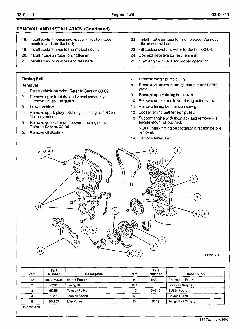
Timing Belt Removal
1. Raise vehicle on hoist. Refer to Section 00-02.
2. Remove right front tire and wheel assembly. Remove RH splash guard.
3. Lower vehicle. 4. Remove spark plugs. Set engine timing to TDCon
No. 1 cylinder.
5. Remove generator and power steering belts. Refer to Section 03-05.
6. Remove oil dipstick.
7. Remove water pump pulley.
8. Remove crankshaft pulley, damper and baffle plate.
9. Remove upper timing belt cover. 10. Remove center and lower timing belt covers.
11. Remove timing belt tension spring.
12. Loosen timing belt tension pulley.
13. Support engine with floor jack and remove RH engine mount as outlined.
NOTE: Mark timing belt rotation direction before removal.
14. Remove timing belt.
(Continuedl
1993Capl8 July, 195
03-01-12 Engine, 1.6L 03-01-12
REMOVAL AND INSTALLATION (Continued)
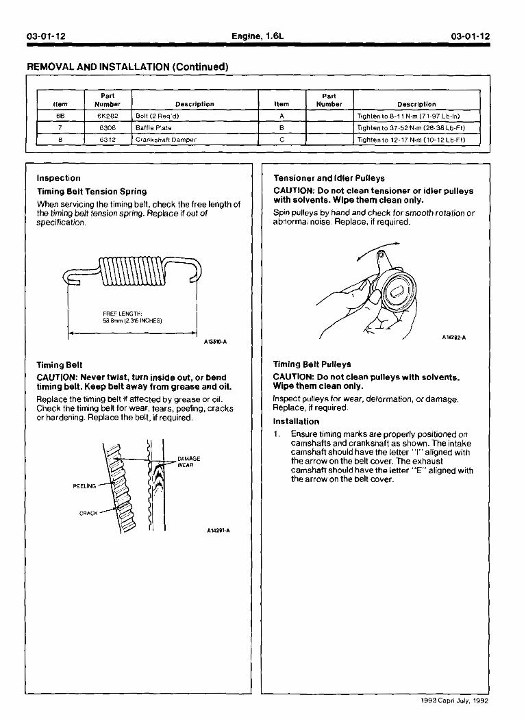
Inspection
Timing Belt Tension Spring
Item
66
7
8
When servicmo the timino belt, check the free lenath of the timing behiension spring. Replace if out of specification.
Part Nurnbar
6K282
6306
03 12
I FREE LENGTH: 58 Bmm (2 315 INCHES)
Timing Belt
CAUTION: Never twist, turn inside out, or bend timing belt. Keep belt away from grease and oil. Replace the timing belt if affected by grease or oil. Check the timing belt for wear. tears, peeling, cracks or hardening. Replace the belt, if required.
Oes~ript ion
Bolt (2 Req'd)
Baff le Plate
Crankshall Damper
DAMAGE WEAR
PEELING
CRACK
AUZB1.A
Tensioner and Idler Pulleys
Item
A
B
C
CAUTION: Do not clean tensioner or idler pulleys with solvents. Wipe them clean only. Spin pulleys by hand and check for smooth rotation or abnormal noise Replace, if required.
Timing Belt Pulleys CAUTION: Do not clean pulleys with solvents. Wipe them clean only. Inspect pulleys for wear, deformation, or damage. Replace, if required.
Installation
Part Number
1 Ensde tim~ng marks are properly posmonea on camshafts and cranksnaft as snown. The nta<e camshah shoud have the ,etter I" allonea w.tn
Description
T igh ten loB~11 N m ( 7 1 ~ 9 7 Lb-In)
Tighten to 37-52 Nm (28-38 L b ~ F t )
Tightento 12-17 Nm(10-12Lb-Ft)
the arrow on the belt cover. The exhaust camshaft should have the letter "E" alianed with the arrow on the belt cover.
1993Capri July, 199;
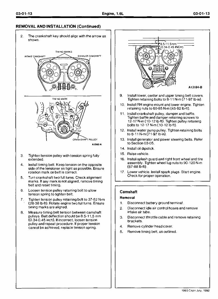
2. The crankshaft key should align with the arrow as shown
TIMING MARKS
INTAKE
TIMING MnRK
Tighten tension pulley with tension spring fully extended.
lnstall timing belt. Keep tension on the opposite side of the tensioner as tight as possible. Ensure rotation mark on belt is correct.
Turn crankshaft two full turns. Check alignment marks. If any mark is not aligned, remove timing belt and reset timing.
Loosen tension pulley retaming bolt to allow tension spring to tighten belt.
Tighten tension pulley retaining bolt to 37-52 N m (28-38 lb-ft). Rotate engine two full turns. Ensure timing marks are aligned.
Measure timing belt tension between camshaft pulleys Belt deflection should be 8.5-1 1.5 mm (0.34-0.45 inch). If incorrect, loosen tension pulley and repeat procedure. If proper tension cannot be achieved, replace tension spring.
9. lnstall lower, center and upper timing belt covers. Tighten retaining bolts to 8-1 1 N.m (71-97 lb-in).
10. Install RH engine mount and lower engine. Tighten retaining nuts to 60-85 N m (45-62 Ib-ft).
11. lnstall crankshaft pulley, damper and baffle. Tighten baffle and damper retaining screws to 12-17 N m (10-12 Ib-ft). Tighten pulley retaining bolts to 12-17 N m (10-12 Ib-ft).
12. Install water pump pulley. Tighten retaining bolts to 8-1 1 N.m (71-97 lb-in).
13. lnstall generator and power steering belts. Refer to Section 03-05.
14. lnstall oil dipstick.
15. Raise vehicle.
16. Install splash guard and right front wheel and tire assembly. Tighten wheel k g nuts to 90- 120 N.m (67-88 lb-ft).
17. Lower vehicle, lnstall spark plugs. Start engine, Check for proper operation.
Camshaft Removal
1. Disconnect battery ground terminal.
2. Disconnect idle air control hoses and remove intake air tube.
3. Disconnect throttle cable and remove retaining brackets.
4. Remove cylinder head cover.
5. Remove timing belt, as outlined.
03-01-14 Engine, 1.6L 03-01-14
REMOVAL AND INSTALLATION (Continued)
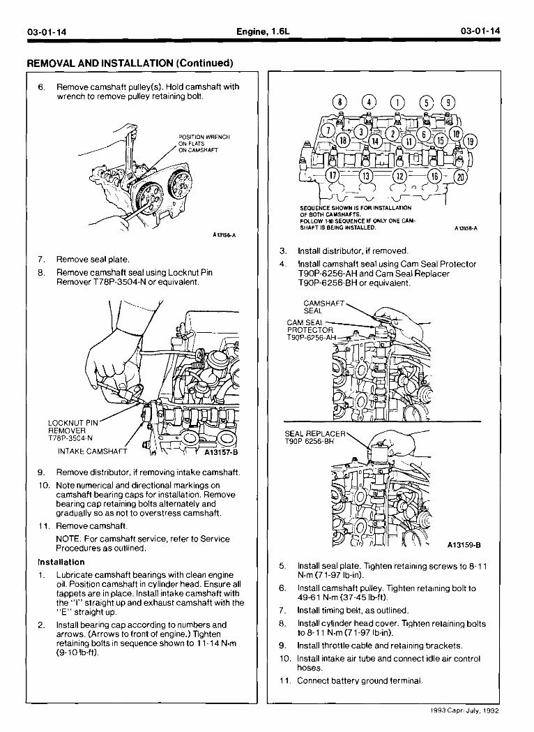
Remove camshaft pulley(s). Hold camshaft with wrench to remove pulley retaining bolt.
Remove seal plate.
Remove camshaft seal using Locknut Pin Remover T78P-3504-N or equivalent.
SEOUE~CE SHOWN IS FOR INSTALLATION OF BOTH CAMSHAFTS. FOLLOW 1.W SEQUENCE IF ONLY ONE CAM- SHAFT IS BEING INSTALLED. Al358.A
lnstall distributor, if removed.
lnstall camshaft seal using Cam Seal Protector T90P-6256-AH and Cam Seal Replacer T90P-6256-BH or equivalent.
SEAL REPLACER T90P~6256-BH
9. Remove distributor, if removing intake camshaft
10. Note numerical and directional markings on camshaft bearina cam for installation. Remove bearing cap retahind bolts alternately and gradually so as not to overstress camshaft.
1 1. Remove camshaft. NOTE: For camshaft service, refer to Service Procedures as outlined.
Installation
1. Lubricate camshaft bearings with clean engine oil. Position camshaft in cylinder head. Ensure all lappets are in place. lnstall intake camshaft with the "I" straight up and exhaust camshaft with the "E" straight up.
2. lnstall bearing cap according to numbers and arrows. (Arrows to front of engine.) Tighten retaining bolts in sequence shown to 11-14 N.m (9-10 lb-ft).
Install seal plate. lighten retaining screws to 8-1 1 N.m (71-97 Ib-in).
lnstall camshaft pulley. Tghten retaining bolt to 49-6 1 N.m (37-45 lb-ft).
lnstall timing belt, as outlined.
lnstall cylinder head cover. Tghten retaining bolts to8-1 1 N.m (71-97 Ib-in).
lnstall throttlecable and retaining brackets.
lnstall intake air tube and connect idle air control hoses.
Connect battery ground terminal.
03-01-15 Enaine. I .6L 03-01-15
REMOVAL AND INSTALLATION (Cont inued)
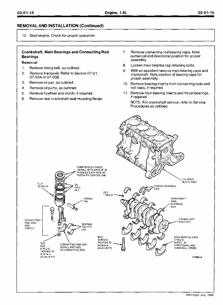
12. Start engine. Check for proper operation. I Crankshaft, Main Bearings and Connecting Rod Bearings
Removal
1. Remove timing belt, as outlined.
2. Remove transaxle. Refer to Section 07-01, 07-03A or 07-03B.
3. Removeoil pan, as outlined.
4. Remove oil pump, as outlined.
5. Remove flywheel and clutch, if required.
6. Remove rear crankshaft seal mounting flange
7. Remove connecting rod bearing caps. Note numerical anddirectional position for proper assembly.
8. Loosen main bearing cap retaining bolts.
9. With an assistant remove main bearing caps and crankshaft. Note position of bearing caps for proper assembly.
10. Remove bearing inserts from connecling rods and rod caps, if required.
11. Remove main bearing inserts and thrust bearings, if required.
NOTE: For crankshaft service, refer to Service Procedures as outlined.
COMPRESSION RINGS -INSTALL WITH GAPS AT 30 DEGREES EACH SIDE OF PlSmIv PIN CENTER LINE
BLOCK ASSY
THRUST BtARINGS
CRANKSilAFT
DIRECTIONAL AND
E R E O D INSTALL MATCHED NUMERlCiiL ORDER m CONNECTING ROD
4152 N m (35.38 LB-FTI A15160.A
1 9 9 3 Capri July. 199:
03-01-16 Ensine. 1.6L 03-01-16
REMOVAL AND INSTALLATION Continued)
Installation
1, lnstall upper connecting rod bearing inserts, if removed
2. lnstall upper main bearing inserts, if removed.
3. lnstall lower main bearing inserts into main bearing caps.
4. With an assistant, install crankshaft using No. 2 bearing and cap.
5. lnstall thrust bearings.
6. lnstall remaining main bearings. Tghten retaining bolts to 54-59 N.m (40-43 Ib-ft).
7 lnsla oaer connect ng rod Dear~ng ~nserls, f removea lnsla I rod Dearmg caps Fghten relan ng nuls to 47-52 b m (35-38 ID-11)
8. lnstall rear crankshaft seal mounting flange. Tighten retaining bolts to 8-1 1 N.m (71-97 Ib-in).
9. lnstall flywheel and clutch, if removed. Apply Threadlock and Sealer EOAZ-19554-AA (ESE-M4G204-A) (Type II) or equivalent to flywheel retaining bolts. Xghten bolts to 96-103 N.m (7 1-76 lb-ft).
10. lnstall oil pump. as outlined.
11. lnstall oil pan, as outlined.
12. lnstall transaxle. Refer to Section 07-01, 07-03A or 07-038.
13. Install timing belt. as outlined.
14. Start engine. Check for leaks and proper operation.
In take Manifold
Removal
1. Disconnect negative battery terminal.
2. Relieve fuel system pressure. Refer to Section 03-04A.
3. Drain cooling system. Refer to Section 03-03.
4. Disconnect charge air cooler hose andlor air intake tube. Disconnect idle air control hoses.
5 D sconnecl man eng ne narness e ectrica connecl~on and TP sensor connector
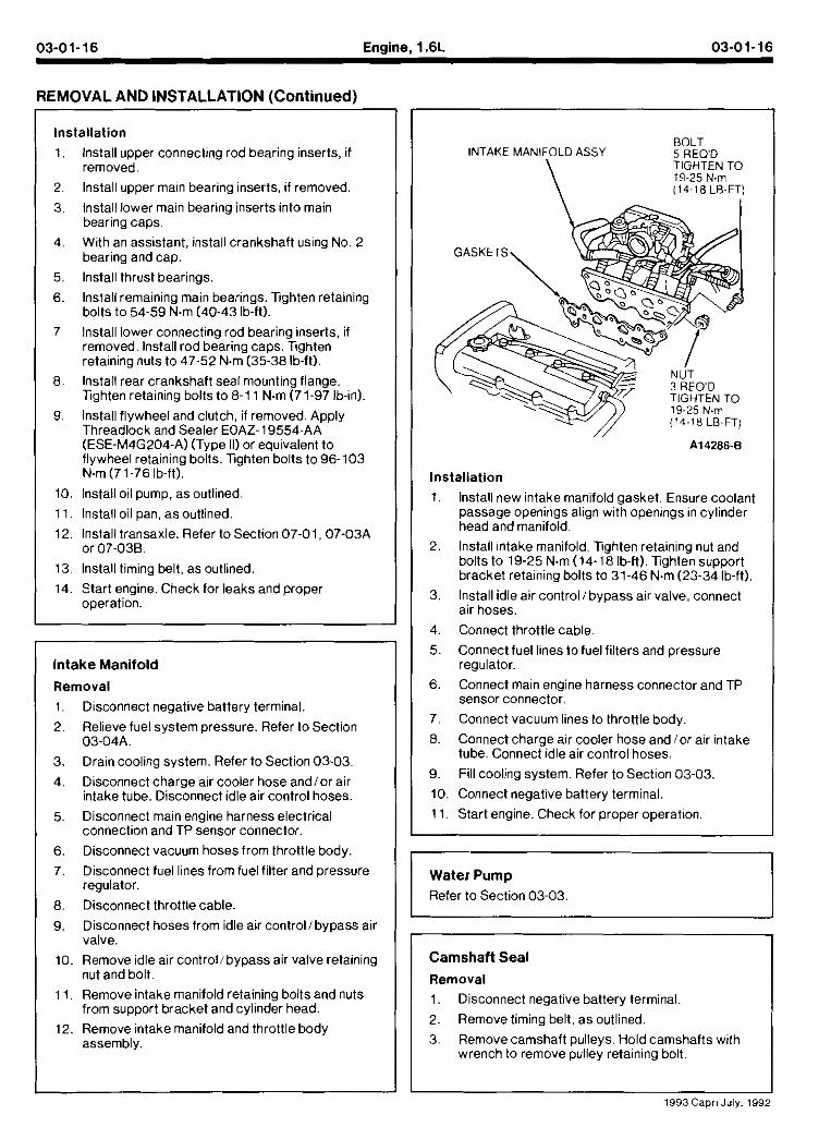
BOLT INTAKE MANIFOLD ASSY 5 REO'D
\ TIGHTEN TO 19-25 N.m (14-18 LB-FT)
Installation
1, lnstall new intake manifold gasket. Ensure coolant passage openings align with openings in cylinder head and manifold.
2. lnstall intake manifold. Tghten retaining nut and bolts to 19-25 N.m (14- 18 Ib-ft). Tighten support bracket retaining bolts to 31-46 N.m (23-34 Ib-ft).
3. lnstall idle air control1 bypass air valve, connect air hoses.
4. Connect throttle cable.
5. Connect fuel lines to fuel filters and pressure regulator.
6. Connect main engine harness connector and TP sensor connector.
7. Connect vacuum lines to throttle body.
8. Connect charge air cooler hose and lor air intake tube. Connect idle air control hoses.
9. Fill cooling system. Refer to Section 03-03.
10. Connect negative battery terminal.
11. Start engine. Check for proper operation.
6. Disconnect vacuum hosesfrom throttle body. I , I
10. Remove idle air control/ bypass air valve retaining nut and bolt.
7. Disconnect fuel lines fromfuel filter and pressure regulator.
8. Disconnect throttle cable.
9. Disconnect hoses from idle air controllbypass air valve.
11. Remove intake manifold retaining bolts and nuts from support bracket and cylinder head.
12. Remove intake manifold and throttle body assembly.
Water Pump
Refer to Section 03-03.
Camshaft Seal
Removal
1. Disconnect negative battery terminal.
2. Remove timing belt, as outlined.
3. Remove camshaft pulleys. Hold camshafts with wrench to remove pulley retaining bolt.
I I 1993Capr1 July. 199:
03-01-17 Engine, 1.6L 03-01-17
REMOVAL AND INSTALLATION (Continued)
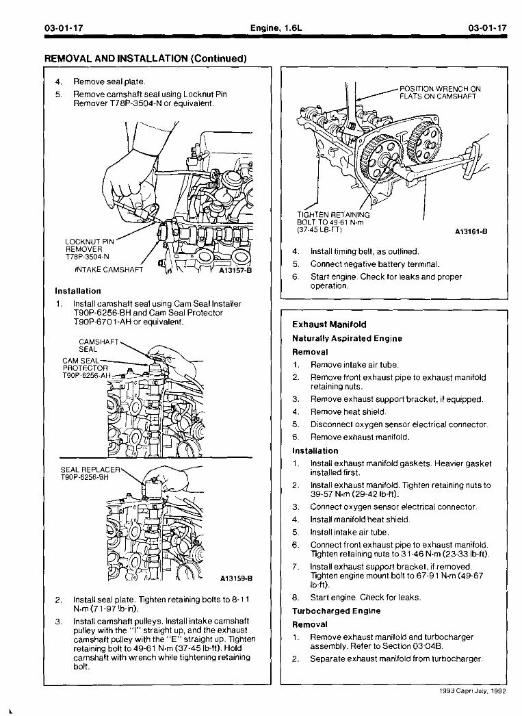
4. Remove seal plate.
5. Remove camshaft seal using Locknut Pin Remover T78P-3504-N or equivalent.
Installation
1. Install camshaft seal using Cam Seal Installel T90P-6256-BH and Cam Seal Protector T90P-6701-AH or equivalent.
2, Install seal plate. lighten retaining bolts toe-11 N.m (7 1-97 Ib-in).
3. Install camshaft pulleys. lnstall intake camshaft pulley with the "I" straight up, and the exhaust camshaft pulley with the "Em straight up. lighten retaining bolt to 49-61 N.m (37-45 Ib-ft). Hold camshaft with wrench while tightening retaining bolt.
POSITION WRENCH ON FLATS ON CAMSHAFT
T ~ H T E N RETAINING' BOLT TO 49-61 N m
I (37-45 LB-FT) A13161-B
4. Install timing belt, as outlined. 5. Connect negative batlery terminal.
6. Start engine. Check for leaks and propel operation.
Exhaust Manifold
Naturally Aspirated Engine
Removal
1. Remove intake air tube. 2. Remove front exhaust pipe to exhaust manifold
retaining nuts.
3. Remove exhaust support bracket, if equipped. 4. Remove heat shield.
5. Disconnect oxygen sensor electrical connector. 6. Remove exhaust manifold
Installation
1, lnstall exhaust manifold gaskets. Heavier gasket installed first.
2. lnstall exhaust manifold. Tghten retaining nuts to 39-57 N.m (29-42 Ib-ft).
3. Connect oxygen sensor electrical connector.
4. lnstall manifold heat shield.
5, lnstall intake air tube.
6. Connect front exhaust pipe to exhaust manifold. lighten retaining nuts to 31-46 N.m (23-33 lb-ft).
7. lnstall exhaust support brackel, if removed. lighten engine mount bolt to 67-91 N.m (49-67 lb-ft).
8. Start engine. Check for leaks.
Turbocharged Engine
Removal 1. Remove exhaust manifold and turbocharger
essembly. Refer to Section 03-046. 2. Separate exhaust manifold from turbocharger.
1993Caprl July, 199:
03-01-18 Engine, 1.6L 03-01-18
REMOVAL AND INSTALLATION (Continued) I l l
Valve Stem Seals
Cylinder Head Installed
Removal and Installation
1. Remove timing belt and camshafts, as outlined.
2. Remove spark plugs.
3. To replace valve stem seals:
a. Rotate crankshaft to bring piston to TDC.
b. Pressurize cylinder with air uslng Rotunda Engine Cylinder Air Pressurization Kit 014-00705 or equivalent.
c. Remove hydraulic valve adjuster.
d. Remove valve spring and keepers using Valve Spring Compressor T89P-6565-A, Pivot Bar T87C-6565-A. Valve Spring Compressor Brackets T89P-6565-AZ and Valve Spring Compressor Screw Set T90P-6565-AH or equivalent.
Installation
1. lnstall manifold to turbocharger assembly with new gasket. Xghten retaining nuts to 27-33 N m (20-24 lb-ft).
2, lnstall exhaust manifold and turbocharger assembly. Refer to Section 03-046.
Throttle Body
Refer to Section 03-04A.
Raise vehicle. Refer to Section00-02.
Drain engine oil.
Remove frame brace retaining bolt. Loosen RH A-arm front bolt and pivot bracedownward.
Disconnect front exhaust pipe from exhaust manifold or turbocharger.
Remove front exhaust pipe bracket retaining bolts.
Loosen rubber exhaust hangers at catalyst. Allow exhaust to hang supported by mechanic's wire.
Disconnect turbocharger oil return hose, if required.
Remove oil pan retaining bolts.
Carefully pry oil pan loose from cylinder block.
CAUTION: Do not forcea prying tool between cylinder block and oil pan gasket surfaces.
e. Remove valve stem seal using Valve Stem Seal Remover T89P-6510-D or equivalent.
f. Lubricate new valve stem seal. Install seal using Valve Stem Seal Replacer T90P-65 10-AH or equivalent.
4. Repeat procedure for each cylinder. Keep air charge ineach cylinder until all valve springs in that cylinder are securely installed.
5. lnstall spark plugs.
6. lnstall camshafts and timing belt, as outlined.
1993 Capri July, 1992
REMOVAL AND INSTALLATION [Continued) ~~ ~~ .
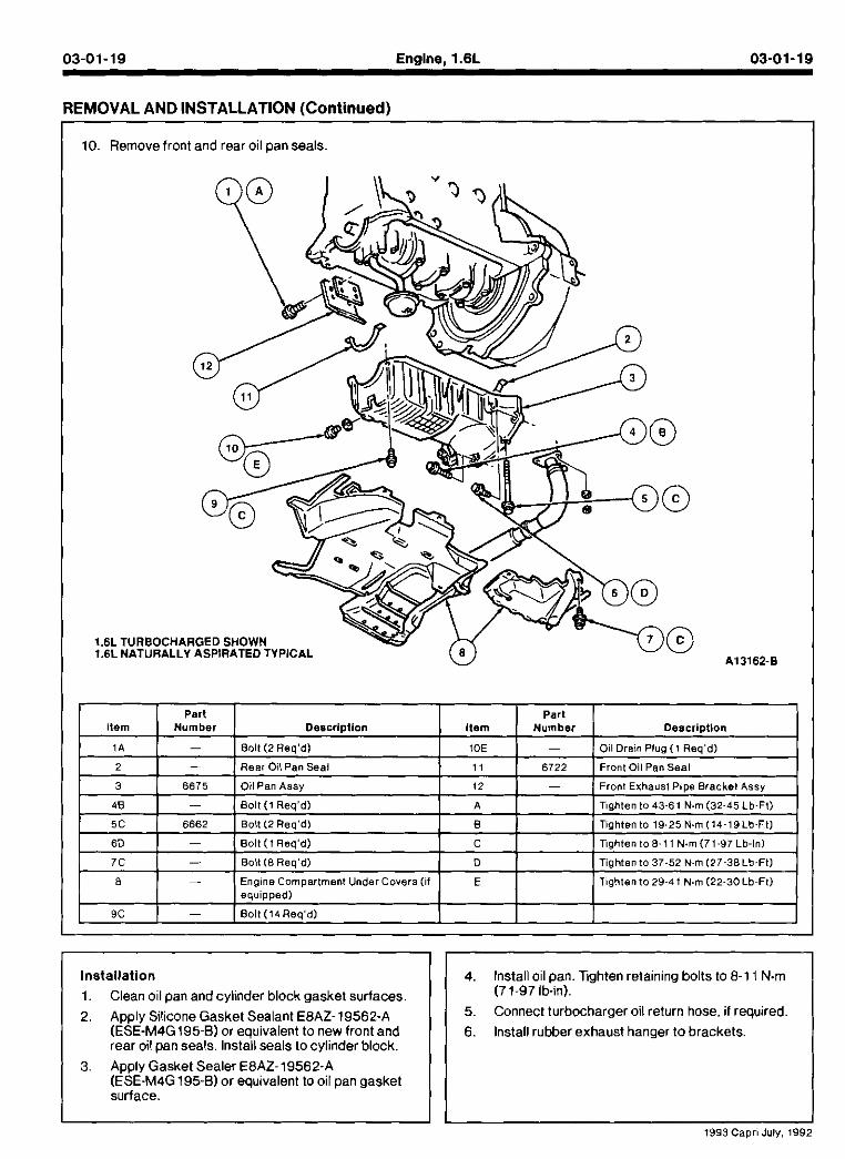
10. Remove front and rear oil pan seals.
.TURBOCHARGED SHOWN
.NATURALLY ASPIRATED TYPICAL
Installation 1. Clean oil pan and cylinder block gasket surfaces.
2. Apply Silicone Gasket Sealant E8AZ-19562-A (ESE-M4G195-8) or equivalent to new front and rear oil pan seals. Install seals to cylinder block.
3. Apply Gasket Sealer E8AZ-19562-A (ESE-M4G 195-8) or equivalent to oil pan gasket surface.
4. Install oil pan. lighten retaining bolts to 8-1 1 N m (7 1-97 lb-in).
5. Connect turbocharger oil return hose, if required
6. Install rubber exhaust hanger to brackets.
I I I 1993 Caprl July, 1992
03-01-20 Enaine. 1.6L 03-01-20
REMOVAL AND INSTALLATION (Continued)
7, lnstall new gasket and connect front exhaust pipe to exhaust manifold or turbocharger. lighten retaining nuts for naturally aspirated engines, to 31-46 N.m (23-34 Ib-ft). For turbocharged engines. tighten nuts to 24-32 N m (18-23 Ib-It).
8. lnstall front exhaust pipe bracket. Tighten retaining bolts to43-61 N m (32-45 lb-ft).
9. Pivot chassis cross brace into position. Tighten retaining bolt to crossmember to 35-50 N m (26-36 lb-ft). Tighten RH A-arm front retaining bolt to 97-1 17 N m (72-86 Ib-ft).
10. Lower vehicle.
11. Fill engine oil. Start engine and check for leaks.
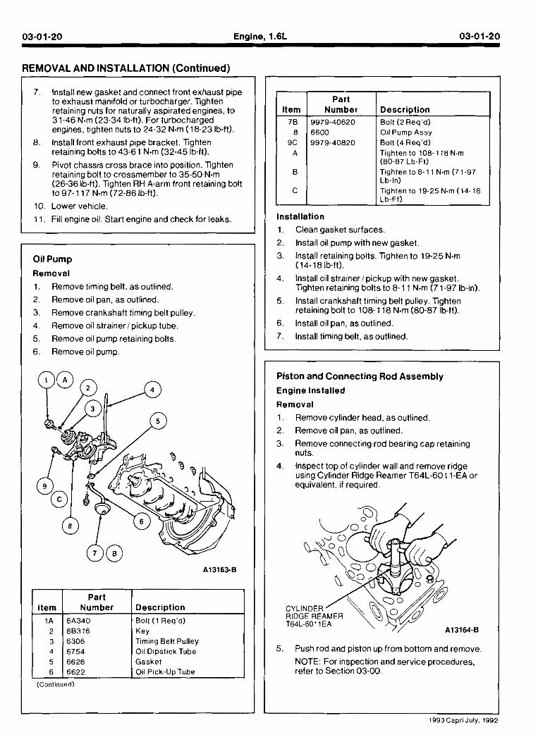
Oil Pump
Removal
1. Remove timing belt, as outlined.
2. Remove oil pan, as outlined.
3. Remove crankshaft timing belt pulley.
4. Remove oil strainerlpickup lube.
5. Remove oil pump retaining bolts.
6. Remove oil pump.
I I part I Number Description
Timing Belt Pulley 6754 Oil Dipstick Tube 6626 Gasket
6 6622 Oil Pick-Up Tube (Continued)
Installation
1. Clean gasket surfaces.
2. Install oil pump with new gasket.
Part Number
9979 -40620
6 6 0 0 9979 -40820
3. lnstall retaining bolts. Tighten to 19-25 N m (14-18 lb-It).
Description Bolt (2 Req'd) Oil Pump Assy
Bolt (4 Req'd) Tighten to 108 -1 18 N.m (80-87 Lb-Ft) Tighten toe-1 1 N m (71-97 Lb-In) Tighten to 19-25 N m (14-18 Lb-Ft) -
4 lnslal o I stra ner p.cm,p w tn new gasmet lighten reta nmg bolts to 8- 1 1 N m (7 1-97 lb-~n)
5. lnstall crankshaft timing belt pulley. lighten retaining bolt to 108-1 18 N m (80-87 lb-It).
6, lnstall oil pan, as outlined.
7. lnstall timing belt, as outlined.
I Piston and Connecting Rod Assembly
Engine Installed
Removal
1. Remove cylinder head, as outlined.
2. Remove oil pan, as outlined.
3. Remove connecting rod bearing cap retaining nuts.
4, Inspect top of cylinder wall and remove ridge using Cylinder Ridge Reamer T64L-6011-EA or equivalent, if required.
5. Push rod and piston up from bottom and remove
NOTE: For inspection and service procedures, refer to Section 03-00.
1993Capri July, 1992
03-01-21 Enaine. l.6L 03-01-21
REMOVAL AND INSTALLATION Continued)
Installation
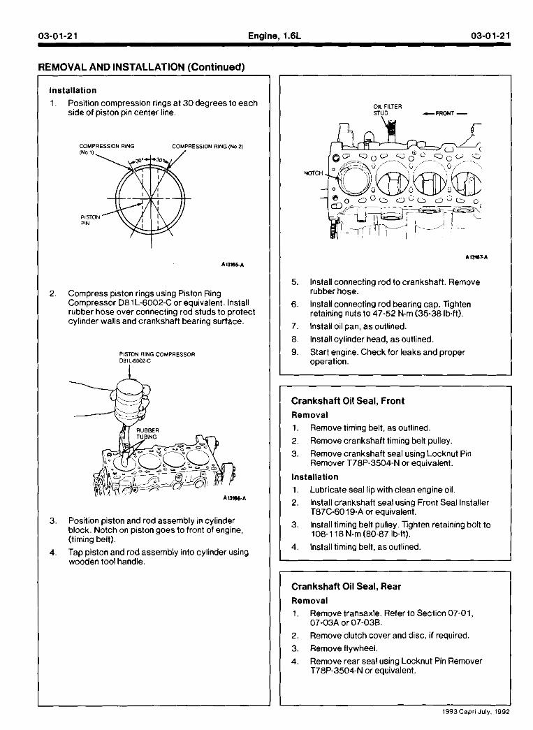
Position compression rings at 30 degrees to each side of piston pin center line.
COMPRESSION RING COMPRESSION RlNG(M 2)
Compress piston rings using Piston Ring Compressor D81L-6002-C or equivalent. Install rubber hose over connecting rod studs to protect cylinder walls and crankshaft bearing surface.
PISTON RlNG COMPRESSOR 081 L.6W2-C
Position piston and rod assembly in cylinder block. Notch on piston goes to front of engine. (timing belt).
Tap piston and rod assembly into cylinder using wooden tool handle.
OIL FILTER STUD c F R O Y T -
5. lnstall connecting rod to crankshaft. Remove rubber hose.
6. lnstall connecting rod bearing cap. Tighten retaining nuts to 47-52 N m (35-38 Ib-ft).
7. lnstall oil pan, as outlined. 8. Installcylinder head, as outlined.
I I 9. Start engine. Check for leaks and proper operation.
Crankshaft Oil Seal, Front
Removal 1. Remove timing belt, as outlined.
2. Remove crankshaft timing belt pulley.
3. Remove crankshaft seal using Locknut Pin Remover T78P-3504-N or equivalent.
Installation
1. Lubricate seal lip with clean engine oil.
2. lnstall crankshaft seal using Front Seal Installer T87C-6019-A or equivalent.
3. lnstall timing belt pulley. Tighten retaining bolt to 108-1 18 N m (80-87 Ib-It).
4. lnstall timing belt, asoutlined
Crankshaft Oil Seal, Rear
Removal
1 . Remove transaxle. Refer to Section 07-01, 07-03A or 07-03B.
2. Remove clutch cover and disc, if required.
3. Remove flywheel.
4. Remove rear seal using Locknut Pin Remover T78P-3504-N or equivalent.
I 1993Caprl July, 1992
03-01-22 Engine, 1.6L 03-01-22
REMOVAL AND INSTALLATION (Continued)
I' lnstallation
1. Lubricate seal lip with clean engine oil
2 Instal crankshaft seal bsing Seal Repacer T87C-6701-A and Screw Set T90P-6565-AH or equivalent.
3, lnstall flywheel. Apply Threadlock and Sealer EOAZ-19554-AA (ESE-M4G204A, Type 11) or equivalent to flywheel retaining bolts. lighten retaining bolts to 96-103 N m (71-76 Ib-ft).
4. lnstall clutch assembly, if required. 5. lnstall transaxle.
Core Plugs
Removal and lnstallation
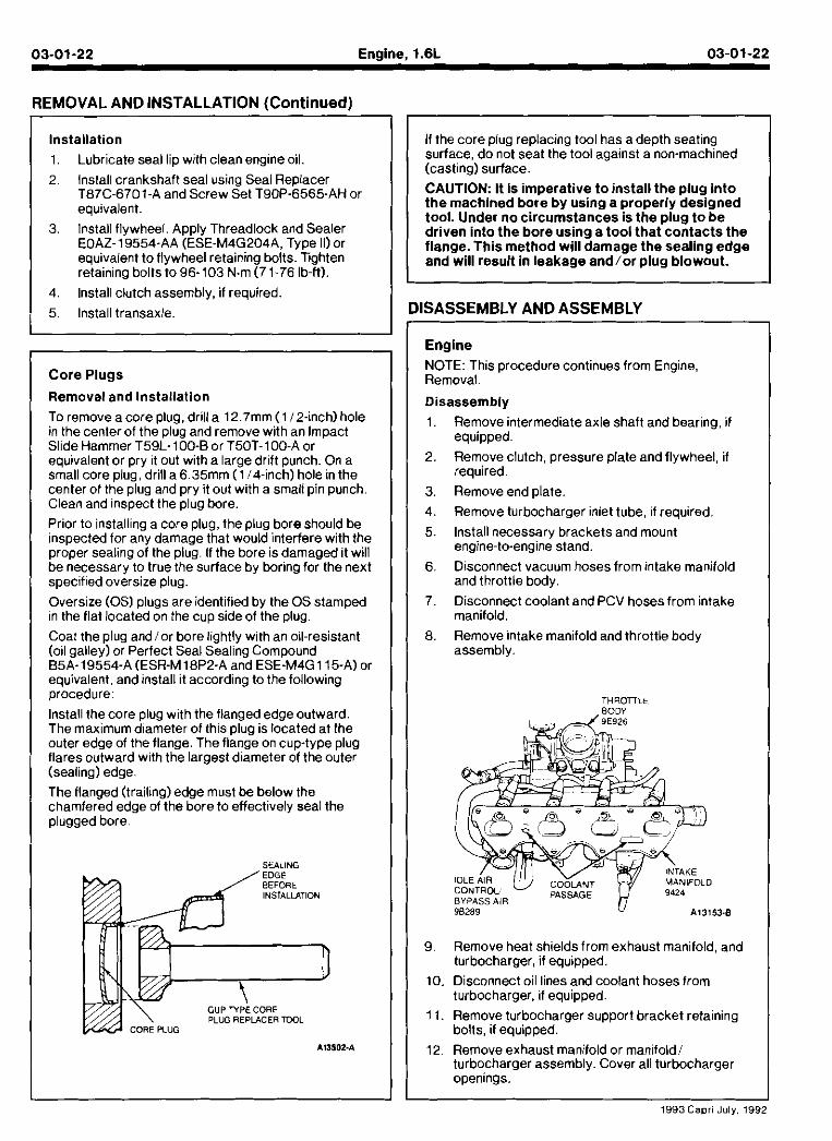
To remove a core plug, drill a 12.7mm (1 12-inch) hole in the center of the plug and remove with an Impact Slide Hammer T59L- 100-B or T50T-100-A or equivalent or pry it out with a large drift punch. On a small core plug, drill a 6.35mm (114-inch) hole in the center of the plug and pry it out with a small pin punch. Clean and inspect the plug bore.
Prior to installing a core plug, the plug bore should be inspected for any damage that would interfere with the proper sealing of the plug. If the bore is damaged it will be necessary to true the surface by boring for the next specified oversize plug.
Overs ze (0s) plugs aredent tied by the OS stamped n the flat ocatea on me cup side of the plug.
Coat the plug andlor bore lightly with an oil-resistant (oil galley) or Perfect Seal Sealing Compound B5A-19554-A (ESR-M 18P2-A and ESE-M4G 115-A) or equivalent, and install it according to the following procedure:
lnstall the core plug with the flanged edge outward. The maximum d~ameter of this plug is located at the outer edge of the flange. The flange on cup-type plug flares outward with the largest diameter of the outer (sealing) edge
The flanged (trai1ing)edge must be below the chamfered edae of the bore to effectivelv seal the plugged bore
SEALING
INSTALLATION
CUP TYPE CORE PLUG REPLACER TWL
I If the core plug replacing tool has a depth seating surface, do not seat the tool against a non-machined
I (casting) surface CAUTION: It Is imperative t o install the plug into the machined bore by using a properly designed tool. Under no circumstances is the plug t o be driven into the bore using a tool that contacts the flange. This method will damage the sealing edge and will result in leakage and/or plug blowout.
DISASSEMBLY AND ASSEMBLY
Engine
NOTE: This procedure continues from Engine, Removal.
Disassembly Remove intermediate axle shaft and bearing, i f equipped.
Remove clutch, pressure plate and flywheel, if required.
Remove end plate.
Remove turbocharger inlet tube, if required.
lnstall necessary brackets and mount engine-to-engine stand.
Disconnect vacuum hoses from intake manifold and throttle body.
Disconnect coolant and PCV hoses from intake manifold. Remove intake manifold and throttle body assembly.
Remove heat shields from exhaust manifold, and turbocharger, if equipped. Disconnect oil lines and coolant hoses from turbocharger, if equipped.
Remove turbocharger support bracket retaining bolts, if equipped. Remove exhaust man fo.d or man.fo~d turoocharger assembly. Cover al turbocharger openings
1993 Capri July. 195
03-01-23 Engine, 1.6L 03-01-23
ISASSEMBLY AND ASSEMBLY (Continued)
I Part I I tem
Turbocharger Support Bracket Oil Return I
2 3 4
5
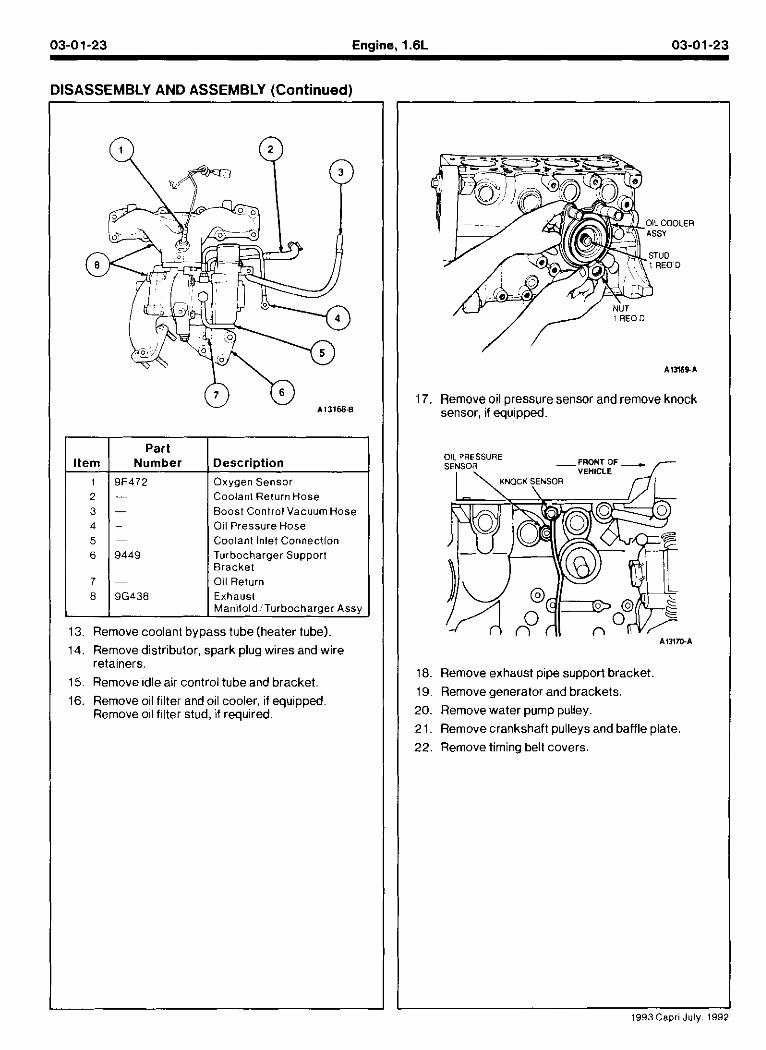
1 19F472 I Oxygen Sensor
~ ~
Number
13. Remove coolant bypass tube(heater tube).
14. Remove distributor, spark plug wires and wire retainers.
15. Remove idle air control tube and bracket.
Descr ipt ion
- - --
-
8
16. Remove oil filter and oil cooler, if equipped Remove oil filter stud, if required.
Coolanl Return Hose Boost Control Vacuum Hose Oil Pressure Hose Coolant Inlet Connection
17. Remove oil pressure sensor and remove knock sensor, if equipped.
9G438
18. Remove exhaust pipe support bracket.
19. Remove generator and brackets.
20. Remove water pump pulley.
21. Remove crankshaft pulleys and baffle plate.
22. Remove timing belt covers.
Exhausl Manltold 'Turbocharger Assy
1993 Capri July. 1992
03-01-24 Engine. 1.6L 03-01-24
DISASSEMBLY AND ASSEMBLY (Continued)
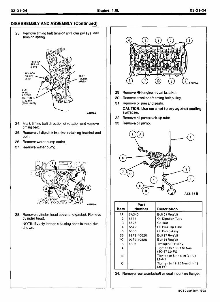
23. Remove timing belt tension and idler pulleys, and tension spring.
24. Mark timing belt direction of rotation and remove timing belt.
25. Remove oil dipstick bracket retaining bracket and bolt.
26. Remove water pump outlet.
27. Remove water pump.
28. Remove cylinder head cover and gasket. Remove cylinder head.
NOTE: Evenly loosen retaining bolts in the order shown.
29. Remove RH engine mount bracket.
30. Remove crankshaft timing belt pulley.
31. Remove oil pan and seals.
CAUTION: Use care not t o pry against sealing surfaces.
32. Remove oil pump pick-up tube.
33. Remove oil pump.
Number
6626 6622 6600
6306
Bolt ( 1 Req'd) Oil Dipstick Tube Gasket Oil Pick-Up Tube Oil Pump Assy Bolt (2 Req'd) Bolt (4 Req'd) Timing Belt Pulley Tighten to 1081 18 N.m (80-87 Lb-Ft) Tighten ( 0 8 - 1 1 N.m (71-97 I ib- In)
1993Capri July. 199
C Tighten to 19-25N.m (14-18 Lb-Ft)
34. Remove rear crankshaft 011 seal mounting flange.
03-01-25 Enalne. 1.6L 03-01-25
DISASSEMBLY AND ASSEMBLY (Continued)
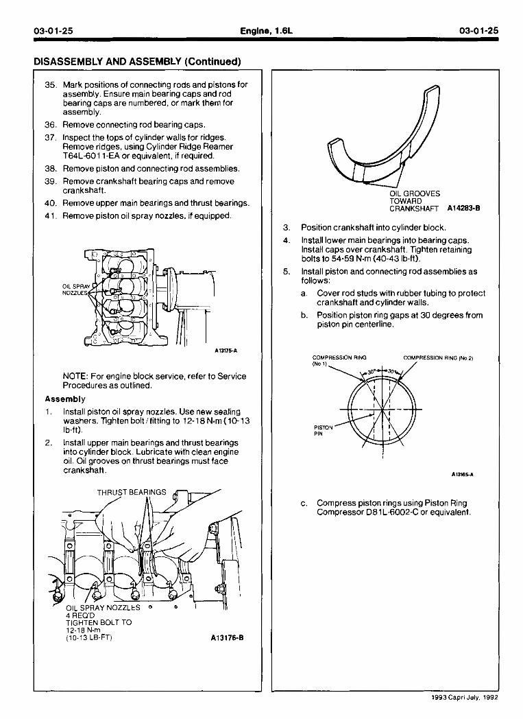
35. Mark positions of connecting rods and pistons for assembly. Ensure main bearing caps and rod bearing caps are numbered, or mark them for assembly.
36. Remove connecting rod bearing caps.
37, Inspect the tops of cylinder walls for ridges. Remove ridaes. usina Cvlinder Ridae Reamer ~ 6 4 i - 6 0 1 1 ~ ~ ~ ' o r equivalent, if required.
38. Remove piston and connecting rod assemblies.
39. Remove crankshaft bearing caps and remove crankshaft.
40. Remove upper main bearings and thrust bearings.
4 1. Remove piston oil spray nozzles, if equipped.
NOTE: For engine block service, refer to Service Procedures as outlined.
Assembly
1. lnstall piston oil spray nozzles. Use new sealing washers. Tighten boltlfitting to 12-18 N m (10-13 Ib-tt).
2. Install upper main bearings and thrust bearings intocylinder block. Lubricate with clean engine oil. Oil grooves on thrust bearings must face crankshaft
12I18 N.m (10-13 LB-FT)
3. Position crankshaft into cylinder block.
4. lnstall lower main bearings into bearing caps. Install caps over crankshaft. Tghten retaining bolts to 54-59 N m (40-43 Ib-ft).
5. lnstall piston and connecting rod assemblies as follows:
a. Cover rod studs with rubber tubing to protect crankshaft and cylinder walls.
b. Position piston ring gaps at 30 degrees from piston pin centerline.
c Compress plslon rmgs uslng Plslon R ng Compressor D81L-6002-C or equ valent
1993Capri July, 199
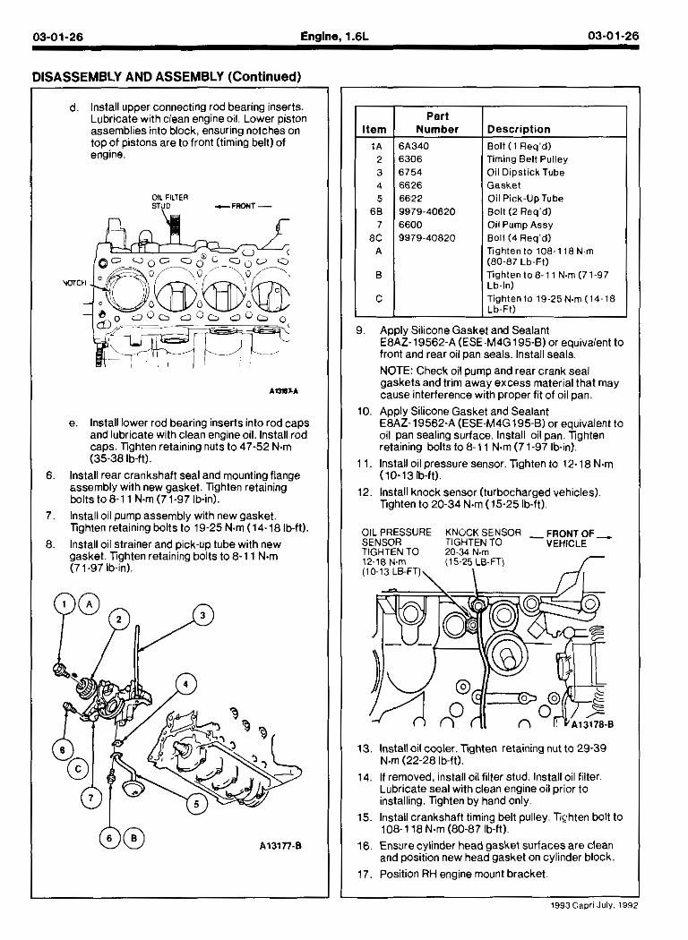
d. lnstall Jpper connecting rod bearlng nserts. Lubrtcate w tn c ean eng ne oil Lower plsron assemblies into block, ensuring notches on top of pistons are to front (timing belt) of engine.
OIL FILTER ~ U D c F R O H T -
e lnstall ower roo bearmg Inserts Into rod caps an0 ubrlcate w th clean eng ne 011. Install rod caps. nghten retaining nuts to 47-52 N.m (35-38 lb-ft).
6. lnstall rear crankshaft seal and mounting flange sssemblv with new oasket. lighten retaining bolts to 8-1 1 N m (77-97 lb-in).
-
7. lnstall oil pump assembly with new gasket. lighten retaining bolts to 19-25 N m (14-18 Ib-ft).
8. lnstall oil strainer and pick-up tube with new gasket. lighten retaining bolts to 8-1 1 N m (71-97 lb-in).
Part I Number 1 Description
6A340 I Bolt ( 1 Rea'd) 6306 Timing Belt Pulley 6754 Oil DipstickTube 6626 Gasket 6622 Oil Pick-UpTube 9979-40620 Bolt (2 Req'd) 6600 Oil Pump Assy 9979-40820 Bolt (4 Req'd)
I Tighten to 108-1 1 (80-87 Lb-Ft) Tighten to 8-1 1 N m (7 1-97 1 Lb-In) Tighten to 19-25N.m (14-18 Lb-Ft)
I Apply Silicone Gasket and Sealant E8AZ-19562-A (ESE-M4G 195-8) or equivalent to front and rear oil pan seals. lnstall seals.
NOTE: Check oil pump and rear crank seal gaskets and trim away excess material that may cause interference with proper fit of oil pan.
D. Apply Silicone Gasket and Sealant E8AZ-19562-A (ESE-M4G195-8) or eauivalent to oil pan sealing &face, lnstall oil pan. lighten retaining bolts to 8-1 1 N m (7 1-97 Ib-in).
1. lnstall oil pressure sensor. lighten to 12- 18 N m (10-13 lb-ft).
2. lnstall knock sensor (turbocharged vehicles). lighten to 20-34 N m (15-25 Ib-ft).
3. lnstall oil cooler. nghten retaining nut to 29-39 N.m (22-28 lb-ft).
4. If removed, install oil filter stud. lnstall oil filter. Lubricate seal with clean engine oil prior to installing. lighten by hand only.
5. Install crankshaft timing belt pulley. Tighten bolt to 108-1 18 N.m (80-87 lb-ft).
6. Ensure cylinder head gasket surfaces are clean and position new head gasket on cylinder block.
7. Position RH engine mount bracket.
03-01-27 Enaine. 1.6L 03-01-27
DISASSEMBLY AND ASSEMBLY (Continued)
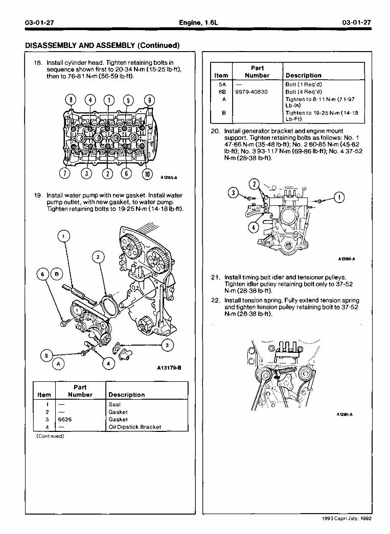
18. lnstall cylinder head. Tighten retaining bolts in sequence shown first to 20-34 N m (15-25 Ib-ft), then to 76-81 N.m (56-59 Ib-ft).
19. lnstall water pump with new gasket. lnstall water pump outlet, with new gasket, to water pump. Tighten retaining bolts to 19-25 N m (14-16 Ib-ft).
Gasket 6626 Gasket
Oil Dipstick Bracket
(Contmued)
I I Part I I
I 6 6 1 9979-40830 1 Bolt (4 Req'd) I
Item
Tighten to 8-1 1 N m (7 1-97 I Lb-In) I
. -. . Number 1 Description
5A I - I Bolt ( 1 Req'd)
20. lnstall generator bracket and engine mount sumort. Tiahten retainina bolts asfollows: No. 1
B
47-66 ~ .mi35.48 ID-ft). Lo. 2 60-85 N.m (45.62 ID-ft): No. 3 93-1 17 N m (69-66 lb-ft): No. 4 37-52
Tighten to 19-25 N.m (14-18 Lb-Ft)
N m (26-38 lb-ft).
21. lnstall timing belt idler and tensioner pulleys. Tighten idler pulley retaining bolt only to 37-52 N m (26-38 lb-fi).
22. lnstall tension spring. Fully extend tension spring and tighten tension pulley retaining bolt to 37-52 N.m (28-38 Ib-ft).
1993Cepri July, 199
03-01-28 Engine, 1.6L 03-01-28
DISASSEMBLY AND ASSEMBLY (Continued)
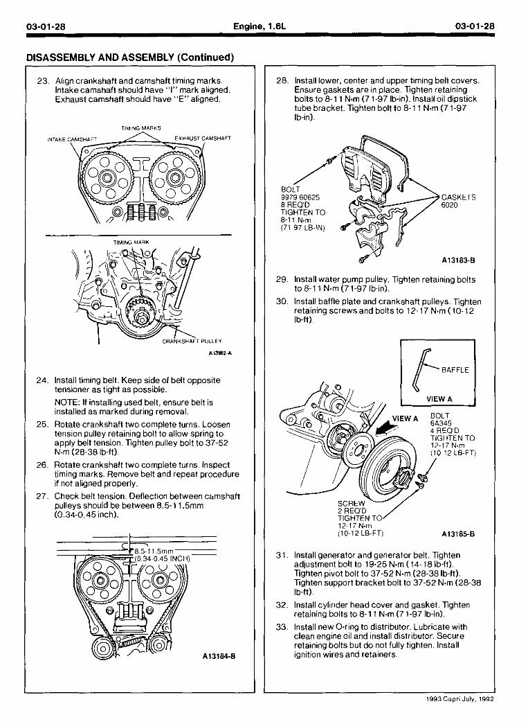
23. Allan crankshaft and camshaft timina marks. lnt&ecamihifl shou d nave. I" ma;k a~~gned Exnaust Camshaft sno,,d nave "EM al gned
TIMING MARKS
TIMING I I A R K
24. lnstall timing belt. Keep sideof belt opposite tensioner as tight as possible.
NOTE: If installing used belt, ensure belt is installed as marked during removal.
25. Rotate crankshaft two complete turns. Loosen tension oullev retainina bolt to allow sorina to apply belt tension. Tighten pulley bolt'to 37-52 N.m (28-38 lb-ft).
26. Rotate crankshaft two complete turns. Inspect timing marks. Remove belt and repeat procedure if not aligned properly.
27. Check belt tension. Deflect~on between chmshaft pulleys should be between 8.5-1 1.5mm (0.34-0.45 inch).
28, lnstall lower, center and upper timing belt covers Ensure gaskets are in place. lighten retaining bolts to 8-1 1 N.m (7 1-97 lb-in). lnslall oil dipstick tube bracket. lighten bolt to 8-1 1 N m (7 1-97 Ib-in).
9979 60625 GASKETS 8 REQ'D 6020 TIGHTEN TO
29. lnstall water pump pulley. Tighten retaining bolts to 8-1 1 N.m (71-97 Ib-in).
30. lnstall baffle plate and crankshaft pulleys. Tighten retaining screws and bolts to 12-17 N m (10.12 Ib-ft).
12-17 N.m (1012 LB-FT) A13185-8
31. Install generator and generator belt. Tighten adjustment bolt to 19-25 N m (14-18 Ib-ft). lighten pivot bolt to 37-52 N m (28-38 lb-ft). lighten support bracket bolt to 37-52 N m (28-38 Ib-ft).
32. Install cylinder head cover and gasket. Tighten retaining bolts to 8-1 1 N.m (7 1-97 lb-in).
33, lnstall new 0-rina to distributor. Lubricate with clean eng ne 01 and nstal d str,ouror Secure reta~nlng 0001s o,t 00 not 1-1 y t ghten lnsta I ignition wires and retainers
1993Capri July, 199
03-01-29 Engine. 1.6L 03-01-29
DISASSEMBLY AND ASSEMBLY (Continued)
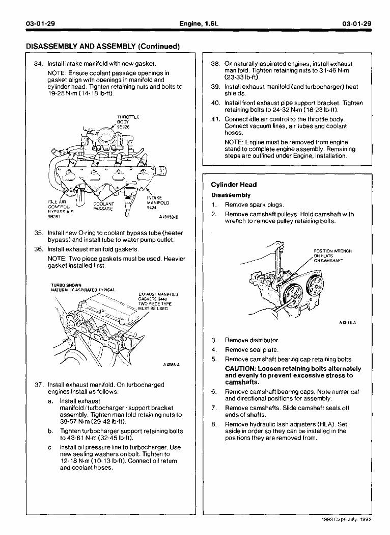
34. Install intake manifold with new gasket.
NOTE: Ensure coolant passage openings in gasket align with openings in manifold and cylinder head. Tighten retaining nutsand bolts to 19-25N.m (14-18 Ib-ft).
THROTTLE eoo; -
BYPASS AiR 98289 113153-8
35, Install new O-ring to coolant bypass tube (heater bypass) and install tube to water pump outlet.
36. lnstall exhaust manifold gaskets. NOTE: Two piece gaskets must be used. Heavier gasket installed first.
37. Install exhaust manifold. On turbocharged engines install as follows:
a. Instan exhaust manifold 1 turbocharger 1support bracket assembly. Tighten manifold retaining nuts to 39-57 N m (29-42 Ib-ft).
b. Tighten turbocharger support retaining bolts to 43-61 N.m (32-45 Ib-ft).
c. lnstall oil pressure line to turbocharger. Use new sealing washers on bolt. Tighten to 12-18 N.m (10-13 Ib-ft). Connect oil return and coolant hoses.
38. On naturally aspirated engines, install exhaust manifold. Tighten retaining nuts to 31-46 N m (23-33 lb-ft).
39. Install exhaust manifold (and turbocharger) heat shields.
40 lnstaql front exnaust plpe support Drac6et T.gnten reta n.ng bolts to 24-32 N.m (18-23 b.11)
41. Connect idle air control to the throttle body. Connect vacuum lines, air tubes and coolant hoses.
NOTE: Engine must be removed from engine stand to complete engine assembly. Remaining steps are outlined under Engine. Installation.
Cylinder Head
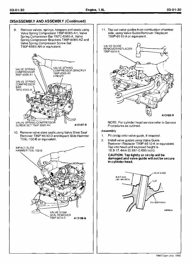
Disassembly Remove spark plugs.
Remove camshaft pulleys. Hold camshaft with wrench to remove pulley retaining bolts.
Remove distributor.
Remove seal plate.
Remove camshaft bearing cap retaining bolts.
CAUTION: Loosen retaining bolts alternately and evenly to prevent excessive stress to camshafts. Remove camshaft bearing caps. Note numerical and directional positions for assembly.
Remove camshafts. Slide camshaft seals otf endsof shafts.
Remove nydra~ IC asn aa.usters (HLA) Set as~de n order so they can be nstal.ea n me positions they are removed from.
1993 Capri July. 195
03-01-30 Engine, 1.6L 03-0 1-30
DISASSEMBLY AND ASSEMBLY (Continued)
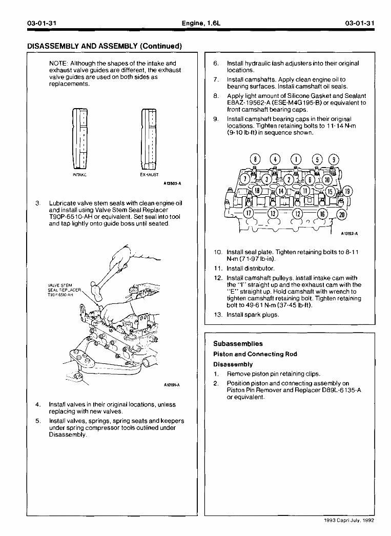
9. Remove valves, springs, keepers and seats using Valve Spring Compressor T89P-6565-A 1. Valve Spring Compressor Bar T87C-6565-A, Valve Spring Compressor Brackets T89P-6565-AZ and Valve Spring Compressor Screw Set T90P-6565-AH or equivalent.
VALVE SPRING VALVE SPRING
COMPRESSOR COMPRESSOR BRACKET
T89P~6565-Al T89P-6565~A2 2 REO'D
10. Remove valve stem seals using Valve Stem Seal Remover T89P-6510-D and Impact Slide Hammer T59L-100-B or equivalent.
IMPACT SLIDE HAMMER T59L-100~B
11. Tap out valve guides from combustion chamber side, using Valve Guide Remover /Replacer T89P-65 10-A or equivalent.
VALVE GUIDE REMOVERIREPLACER T89P-6510-A
\ ,
NOTE: For cylinder head service refer to Service Procedures as outlined.
Assembly
Fit circlip onto valve guide, if required.
Install valve guides using Valve Guide Remover/Replacer T89P-65 IO-A or equivalent. Tap into head until exposed height is 16.8-17.4mm (0.661-0.685 inch).
CAUTION: Tap l ightly or circl ip wil l b e damaged and valve guide wil l n o t b e secure in cylinder head.
1993 Caprl July, 199
03-01-31 Engine, l.6L 03-01-31
llSASSEMBLY AND ASSEMBLY (Continued)
NOTE: Although the shapesof the intake and exhaus! va veg-~aes are a iierent. the exhaust va ve gu aes are ,sea on 00th s~des as
/j INTAKE EXHAUST
AU503-A
3. Lubricate valve stem seals with clean engine oil and install using Valve Stem Seal Replacer T90P-6510-AH or eauivalent. Set seal into tool and tap lightly onto &ide boss until seated
4. lnstall valves in their original locations, unless replacing with new valves.
5, Install valves, springs, spring seats and keepers under spring compressor toolsoutlined under Disassemblv.
6, lnstall hydraulic lash adjusters into their original locations.
7 lnstall camshafts Apply clean englne o I to bearmg surfaces Instah camshaft 01 sea s
8 Apply ~ght amo-nt ol S I cone GaS~et and Sealant E8AZ- 19562-A (ESE-M4G 195-8) or eau,valent to front camshafl bearing caps.
9. lnstall camshaft bearing caps in their original locations. lighten retaining bolts to 11-14 N.m (9-10 lb-ft) in sequence shown.
10. lnstall seal plate. lighten retaining bolts to 8-1 1 N.m (71-97 b in) .
11. lnstall distributor.
12. lnstall camshaft pulleys. lnstall intake cam with the "I" straight up and the exhaust cam with the "E" straight up. Hold camshaft with wrench to tighten camshaft retaining bolt. Tghten retaining bolt to 49-61 N.m (37-45 lb-ft).
13. lnstall spark plugs
Subassemblies
Piston and Connecting Rod
Disassembly
1. Remove piston pin retaining clips.
2. Position piston and connecting assembly on Piston Pin Remover and Replacer D89L-6135-A or equivalent.
I I 1993 Capri July.
03-01-32 Engine. 1.6L 03-01-32
DISASSEMBLY AND ASSEMBLY (Continued)
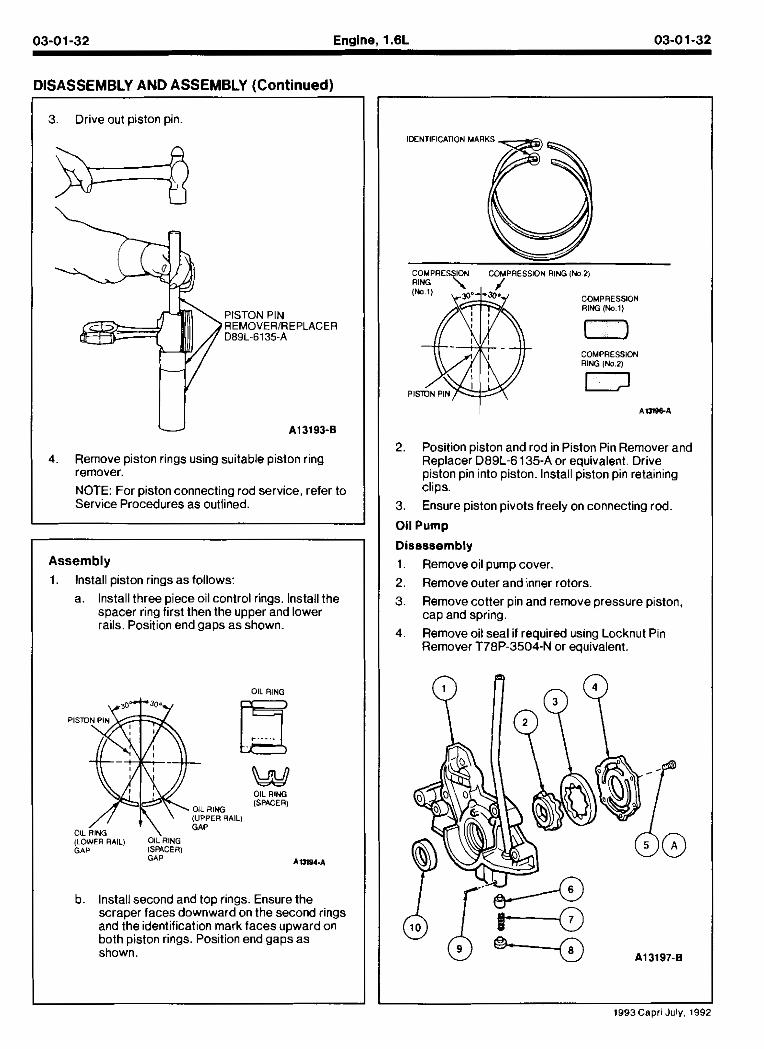
3. Drive out piston pin.
PISTON PIN REMOVERIREPLACER D89L-6135-A
4. Remove piston rings using suitable piston ring remover.
NOTE: For piston connecting rod service, refer to Service Procedures as outlined.
~ ~ - ~ p -
Assembly
1. Install piston rings as follows: a. Install three piece oil control rings. Install the
sDacer rina first then the uooer and lower rails. ~osicon end gaps a i i hown
OIL RING
---...~
w OIL RlNG
OIL R l W [SPACER)
(UPPER RAIL1 GAP
(LOWER RAIL) OIL RlNG GAP ISMCERI
GAP 1111S4.1
b. Install second and too rinas. Ensure the scraper faces downbard-on the second rings and the identification mark faces uoward on both piston rings. Position end gaps as shown.
IDENTIFICATION MARKS
COMPRESSION R l W (No 1)
COMPRESSION RlNG (No 21
2. Position piston and rod in Piston Pin Remover and Replacer D89L-6135-A or equivalent. Drive piston pin into piston. Install piston pin retaining clips.
3. Ensure piston pivots freely on connecting rod.
Oil Pump
Disassembly 1. Remove oil pump cover.
2. Remove outer and inner rotors. 3. Remove cotter pin and remove pressure piston,
cap and spring. 4. Remove oil seal if required using Locknut Pin
Remover T78P-3504-N or equivalent.
1993Cepri July. 19<
03-01-33 Enaine. 1.6L 03-01-33
DISASSEMBLY AND ASSEMBLY (Cont inued)
Part Number
6600
Description
Oil PumD Housina - Inner Rotor Outer Rotor Oil Pump Cover Screw (6 Req'd) Pressure Piston Spring
Cap Cotter Pin Front Crankshaft toi l Pump Seal Tighten to 19-25 N m (14-18 I h-Ft)
NOTE: For oil pump service, refer to Service Procedures as outlined.
Assembly
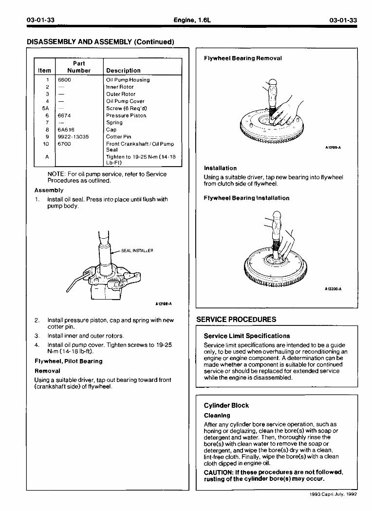
1. Install oil seal. Press into place until flush with pump body.
ii- SEAL INSTALLER
2. Install pressure piston, cap and spring with new cotter pin.
3. Install inner and outer rotors.
4. Install oil pump cover. Tighten screws to 19-25 N m (14-18 Ib-ft).
Flywheel, Pilot Bearing
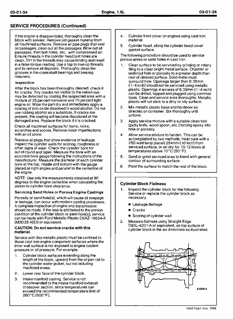
Removal
Using a suitabledriver, tap out bearing toward front (crankshaft side) of flywheel.
Flywheel Bearing Removal
Installation
Using a suitable driver, tap new bearing inlo flywheel from clutch side of flywheel.
Flywheel Bearing Installation
SERVICE PROCEDURES
I Service lmd specif~cations are tnlended lo De a g,lde onlv, to be "sed when overhau ing or recond t~onlng an engme or englne component A determlnatlon can be 1 made whelner a component IS sAaDle lor continued service or should be replaced for extended service while the engine is disassembled.
Cylinder Block Cleaning
After any cylinder bore service operation, such as honing or deglazing, clean the bore(s) with soap or detergent and water. Then, thoroughly rinse the bore(s) with clean water to remove the soapor detergent, and wipe the bore(s) dry with a clean, lint-free cloth. Finally, wipe the bore(s) with a clean cloth dipped in engine oil. . ~
CAUTION: If these procedures are not followed, rusting of the cylinder bore(s) may occur.
1993Capri July. 1992
SERVICE PROCEDURES [Continued)
If the engine is disassembled. thoroughly clean the block with solvent. Remove old gasket material from all machined surfaces. Remove all pipe plugs that seal oil passages, clean out all the passages. Blow out all passages, then bolt holes, etc., with compressed air. Ensure threads in the cylinder head bolt holes are clean. Dirt in the threads may cause binding and result in a false torque reading. Use a tap to true-up threads and to remove all deposits. Thoroughly clean the grooves in the crankshaft bearings and bearing retainers.
Inspection
After the block has been thoroughly cleaned, check it for cracks. l n y cracks not visible to the naked eye may be detected by coating the suspected area with a mixture of 25 percent kerosene and 75 percent light engine oil. Wipe the part dry and immediately apply a coating of zinc oxide dissolved in wood alcohol. Do not use rubbing alcohol as a substitute. If cracks are present, the coating will become discolored at the damaged area. Replace the block if it is cracked.
Check all machined surfaces for burrs, nicks, scratches and scores. Remove minor imperfections with an oil stone.
Replace all plugs that show evidence of leakage. lnspect the cylinder walls for scoring, roughness or other signs of wear. Check the cylinder bore for out-of-round and taper. Measure the bore with an accurate bore gauge following the instructions of the manufacturer. Measure the diameter of each cylinder bore at the top, middle and bottom with the gauge placed at right angles and parallel to the centerline of the engine.
NOTE: Use only the measurements obtained at 90 degrees to the engine centerline when calculating the piston-to-cylinder bore clearance.
Servicing Sand Holes or Porous Engine Castings
Poros~ty or sand hole(s), which will cause oil seepage or leakaae. can occur with modern castina orocesses. A compile lnspectlon of englne and transisston shou d oe made If the eak 1s attrlouted to the oorous cond t on of the cyl nder oloc* or sand ho e(s).'serv ce can oe made wltn Ford Metal IC Plastic C6AZ. 19554-A (M3D35-A(E)) or equivalent.
CAUTION: Do not service cracks with this material.
Service with this metallic plastic must be confined to those cast iron engine component surfaces where the inner wall surface is not exposed to engine coolant pressure or oil pressure. For example:
1. Cvlinder block surfaces extendino alona the length of the block, upward from the oilpan rail to the cvlinder water iacket. but not includina machined areas. .
-
2. Lower rear face of the cylinder block.
3. Intake manifold casting. Service is not recommended to the intake manifold exhaust crossover section. since temoeratures can exceed the recommended tehperature limit of 26O0C(5OO0F).
4. Cylinder front cover on engines using cast iron material.
5. Cylinder head, along the cylinder head cover gasket surface.
The following procedure should be used to service porous areas or sand holes in cast iron.
1. Clean surface to be serviced by grinding or rotary filing to a clean bright metal surface. Chamfer or undercut hole or porosity to a greater depth than rest of cleaned surface. Solid metal must surround hole. Openings larger than 6.35mm (1 14 inch) should not be serviced using metallic plastic. Openings in excess of 6.35mm (1 14 inch) can be drilled, tapped and plugged using common tools. Clean and service area thoroughly. Metallic plastic will not stick to a dirty or oily surface.
Mix metallic plastic base and hardener as directed on container. Stir thoroughly until uniform.
Apply service mixture with a suitable clean tool (putty knife, wood spoon, etc.) forcing epoxy into hole or porosity.
Allow service mixture to harden. This can be accomplished by two methods. Heat cure with a 250-watt lamp placed 254mm (10 inch) from serviced surface, or air-dry for 10-12 hours at temperatures above 10°C (50" F).
Sand or grind serviced area to blend with general contour of surrounding surface.
Paint the surface to match the rest of the block.
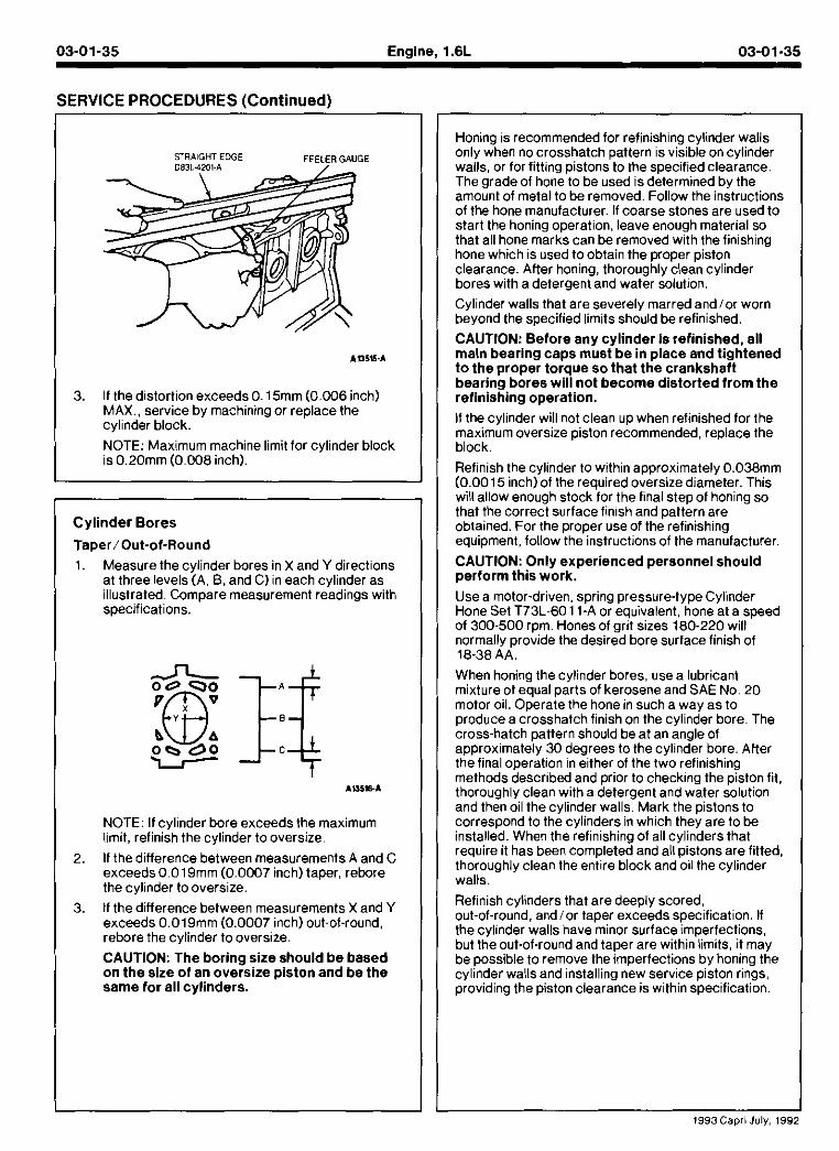
Cylinder Block Flatness
1. lnspect the cylinder block for the following: Service or replace the cylinder block as necessary.
0 Leakage damage
0 Cracks
0 Scoring of cylinder wall
2. Measure flatness using Straight Edge D83L-4201-A or equivalent, on top surface of cylinder block in the six directions as illustrated
1993 Capri July. 1992
03-01-35 Engine, 1.6L 03-01-35
SERVICE PROCEDURES (Continued)
STRAIGHT EDGE FEELER GAUGE
If the distortion exceeds 0.15mm (0.006 inch) MAX.. service by machining or replace the cylinder block.
NOTE: Maximum machine limit for cylinder block is 0.20mm (0.008 inch).
Cylinder Bores
Taper/Out-of-Round
1. Measure the cylinder bores in X and Y directions at three levels (A, 8 , and C) in each cylinder as illustrated. Compare measurement readings with soecifications.
NOTE: If cylinder bore exceeds the maximum limit, refinish the cylinder to oversize.
2. If the difference between measurements A and C exceeds0.019mm (0.0007 inch)taper, rebore the cylinder to oversize.
3. If the difference between measurements X and Y exceeds 0.019mm (0.0007 inch) out-of-round, rebore the cylinder to oversize.
CAUTION: The boring size should be based on the size of an oversize Diston and be the same tor all cylinders.
Honing is recommended for refinishing cylinder walls only when no crosshatch pattern is visible on cylinder walls. or for fittina oistons to the soecified clearance he grade of hoG'to be used is dhtermined by the amount of metal to be removed. Follow the instructions of the hone manufacturer. If coarse stones are used to start the honing operation, leave enough material so that all hone marks can be removed with the finishing hone which is used to obtain the proper piston clearance. Atter honing, thoroughly clean cylinder bores with a detergent and water solution.
Cylinder walls that are severely marred andlor worn beyond the specified limits should be refinished.
CAUTION: Before any cylinder is refinished, all main bearing caps mustbe in place and tightened t o the proper torque so that the crankshaft bearing bores will not become distorted from the refinishing operation.
If the cylinder will not clean up when refinished for the maximum oversize piston recommended, replace the block.
Ref,n~sh tne cyllnaer to wttn n appronmately 0.038mm (0.0015 men) ot the requ rea oversue d.ameter. Th~s WI I al ow enougn stock for tne flna step of non ng so that tne correct s~rface f n.sn and pattern are oatalnea. For the proper use of the reflntshlng eq~ipment, totlow tne 1nstr~ct.ons of the manufacturer
CAUTION: Only experienced personnel should perform this work.
Use a motor-driven, spring pressure-type Cylinder Hone Set T73L-6011-A or equivalent, hone at a speed of 300-500 rpm. Hones of grit sizes 180-220 will normally provide the desired bore surface finish of 18-38 AA.
When honmg the cylinder bores, Lse a ubr~cant m.xt~re of eaual oarts of kerosene and SAE No 20 motor oil. 0peraie the hone in such a way as to produce a crosshatch finish on the cylinder bore. The cross-hatch pattern should be at an angle of a~oroximatelv 30 dearees to the cvlinder bore. Atter tne f~na operhon n etner of tne two ref nlsn ng methods aeSCrl~ed ana orlor to cnecklnq the olston 111. tnoro~gn y clean wlrn a oetergent ana water so Ltlon ana tnen 01 the cyllnder wal s Mark tne p stons to correspord to the cy ~nders n whlch tney are to be Installea Wnen the reftn~shmg 01 a I cy mders tnat req~ire it nas been completed ana a I plstons are f~tted. th0ro~gn.y clean the ent re block and 01, the cy mder walls.
Refinish cylinders that are deeply scored, out-of-round, andlor taper exceeds specification. If the cvlinder walls have minor surface imoerfections. o ~ t the out-of-ro~nd and taper are wlth~n', mats 11 may oe ooss~ble to remove the moerfect~ons oy honlnq the cy hder wa Is ana nstal ing new servce p ston r ~ ~ i s prov~d ng the plston clearance IS w th n spec~f~cat on
03-01-36 Engine, l.6L 03-01-36
SERVICE PROCEDURES (Continued)
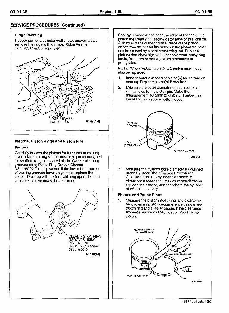
Ridge Reaming
If upper part of a cylinder wall shows uneven wear, remove the ridge with Cylinder Ridge Reamer T64L-60 11-EA or equivalent.
Pistons, Piston Rings and Piston Pins
Pistons
Carefully inspect the pistons for fractures at the ring lands, skirts, oil ring slot corners, and pin bosses, and for scuffed, rough or scored skirts. Clean piston ring grooves using Piston Ring Groove Cleaner D81L-6002-D or equivalent. If the lower inner portion of the ring grooves have a high step, replace the p~ston Tle step w I mterferewltn img operation and cause excess ve rlng s~de clearance
Spongy, eroded areas near the edge of the top of the piston are usuallv caused bv detonation or ore-ianition. A shiny surface of the thrust surface of the bist&, offset from the centerline between the piston pin holes. can be caused by a bent connecting rod. Replace pistons that show signs of excessive wear, wavy ring lands, fractures or damage from detonation or pre-ignition.
NOTE: When replacing piston(s), piston rings must also be replaced.
1. Inspect outer surfaces of piston(s) for seizure or Scoring. Replace piston(s) if required.
2. Measure the outer diameter of each piston at right angles to the piston pin. Make the measurement 16.5mm (0.650 inch) below the lowest oil ring groove bottom edge.
OIL RlNG GROOVE
16 5mm 10 650 INCHI
OUTER DIAMETER
3. Measure the cylinder bore diameter as outlined under Cylinder Block Service Procedures. Calculate piston-to-cylinder clearance. If clearanceexceeds the max mum spec fcat on. replace tne plstons, and or rebore the cyl nder block as necessary.
Pistons and Piston Rings
1 Measure tne paston r~ng.to-rlng and c earance are-nd entare poston c rc,mference Lsmg a new p ston rlng and a lee er gauge. 11 theclearance exceeds maxlmum spec~f cat on, rep ace tne piston
MEASURE ENTIME CIRCUMFERENCE
NEW PISTON RING
1993Capri July. 199
iERVlCE PROCEDURES (Continued)
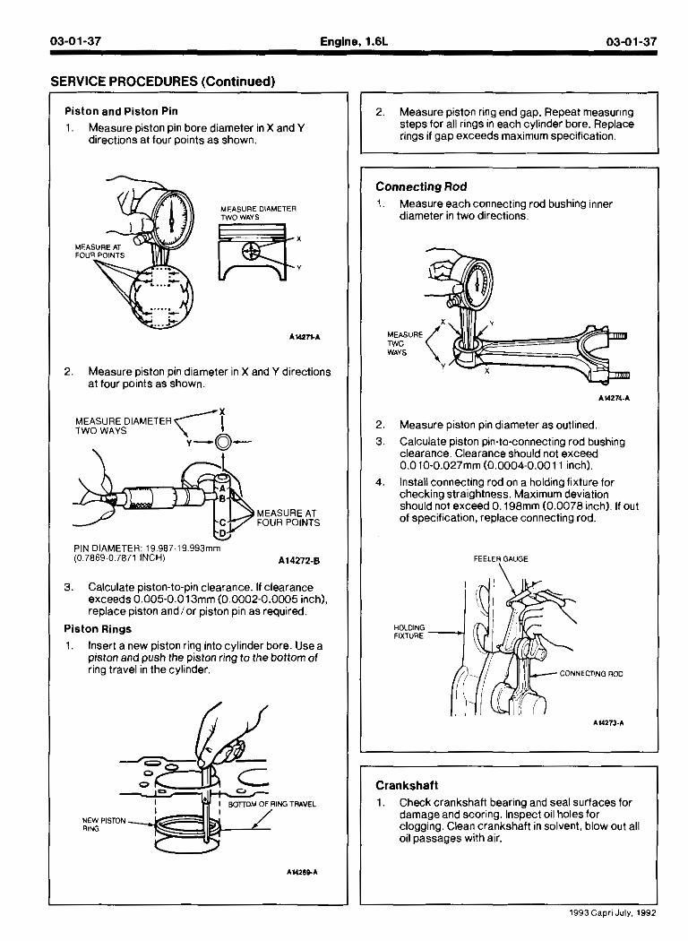
Piston and Piston Pin
1. Measure piston pin bore diameter in X and Y directions at four ooints as shown.
MEASURE DIAMETER TWO WAYS m:
A W n A
2. Measure piston pin diameter in X and Y directions at four points as shown.
MEASURE DIAMETER TWO WAYS
,
PIN DIAMETER: 19.987-19993mm (0.7869-0.7871 INCH1 A14272-8
3. Calculate piston-to-pin clearance. If clearance exceeds 0.005-0.013mm (0.0002-0.0005 inch), replace piston andlor piston pin as required.
Piston Rings
1 . Insert a new piston ring into cylinder bore. Usea piston and push the piston ring to the bottom of ring travel in the cylinder.
/ /
NEW P RlNG
2. Measure piston ring end gap. Repeat measuring steps for all rings in each cylinder bore. Replace rings if gap exceeds maximum specification.
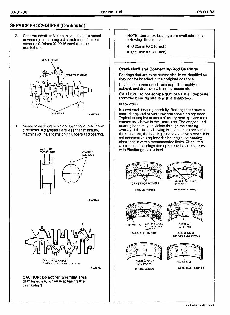
Connecting Rod 1. Measure each connecting rod bushing inner
diameter in two directions.
2. Measure piston pin diameter as outlined. 3 Ca cu,ate plston pin-to-connect ng rod bushmg
c earance C earance sno~ld not exceed 0.010-0.027mm (0.0004-0.001 1 inch).
4. Install connecting rod on a holding fixture for checking straightness. Maximum deviation should not exceed 0.198mm (0.0078 inch). If out of specification, replace connecting rod.
FEELEH GAUGE
Crankshatt
1. Check crankshaft bearing and seal surfaces for damageand scoring. Inspect oil holes for clogging. Clean crankshaft in solvent, blow out all oil passages with air.
-----A 1993 Capri July, 1992
03-01-38 Enaine. 1.6L 03-01-38
SERVICE PROCEDURES (Cont inued)
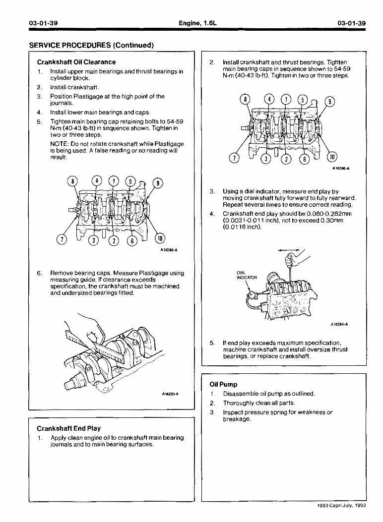
2. Set crankshaft on V-blocks and measure runout at center journal using a dial indicator. If runout exceeds 0.04mm (0.0016 inch) replace crankshaft.
CENTER BEARING
3. Measure each crankoin and bearina iournal in two directions. If diameters are less thin.minimum, machine journals to match on undersized bearing.
FILLET ROLL AREAS DIMENSION R I 5mm (0 06 INCH)
A W V A
NOTE: Undersize bearings are available in the following dimensions:
0.25mm (0.0 10 inch)
0.50mm (0.020 inch)
Crankshatt and Connecting Rod Bearings
Bearings that are to be reused should be identified so they can be installed in their original locations.
Clean the bearing inserts and caps thoroughly in solvent, and dry them with compressed air.
CAUTION: Do not scrape gum or varnish deposits from the bearing shells with a sharp tool.
Inspection
Inspect each bearing carefully. Bearings that have a scorea, cnlpped or worn s~rface shoub oe rep aced Typ ca examples of unsat sfactory oearlngs an0 thev causes are snown in the l ustratlon Tne copper lead oearmg oase may De v s ole thro-gn tne cear ng over ay II the oase snowmg s less tnan 20 percent of the total area, the Dear ng 1s not excess ve y worn It s not necessary to replace-the bearing if the bearing clearance is within recommended limits. Check the clearance of bearings that appear to be satisfactory with Plastigage as outlined.
BRIGHT IPOLISHtOl CRATERSOR POCKETS SECTIONS
FATIGUE FAILURE IMPROPER SEATING
\ I DIRT IMBEDDED OVERLAY INTO BEARING WIPED OUT MATERIAL
SCRATCHEO BY DIRT LACK OF OQ OR IMPROPER CLEARANCE
OVERLAY GONE RADIUS RIDE FROM EDGES
HOUROLASSING RADIUS AIDE A14284~A
CAUTION: Do not remove fillet area (dimension R) when machining the crankshaft.
1993Capri July, 199
03-01-39 Engine, 1.6L 03-01-39
SERVICE PROCEDURES (Continued)
Crankshaft Oil Clearance Install upper main bearings and thrust bearings in cylinder block.
Install crankshaft.
Position Plastigage at the high point of the journals.
Install lower main bearings and caps.
lighten main bearing cap retaining bolts to 54-59 N.m (40-43 lb-ft) in sequence shown. lighten in two or three steps.
NOTE: Do not rotate crankshaft while Plastigage is being used. A false reading or no reading will result.
Remove bearing caps. Measure Plastigage using measuring guide. If clearance exceeds specification, the crankshaft must be machined and undersized bearings fitted.
Crankshaft End Play
1. Apply clean engine oil to crankshaft main bearing journals and to main bearing surfaces.
Install crankshaft and thrust bearinas. lahten mam Dearmg caps in seq-ence shgwn 1654-59 N.m (40-43 b f t ) lghten In two or tnree steps
Using a dial indicator, measure end play by moving crankshaft fully forward to fully rearward. Repeat several times to ensure correct reading.
Crankshaft end play should be 0.080-0.282mm (0.0031-0.01 1 inch), not toexceed 0.30mm (0.01 18 inch).
If end play exceeds maximum specification, machine crankshaft and install oversize thrust bearings, or replace crankshaft.
Oil Pump
1 Disassemble oil pump as outlined.
2. Thoroughly clean all parts
3. Inspect pressure spring for weakness or breakage.
03-01-40 Engine, 1.6L 03-01-40
ERVICE PROCEDURES (Continued)
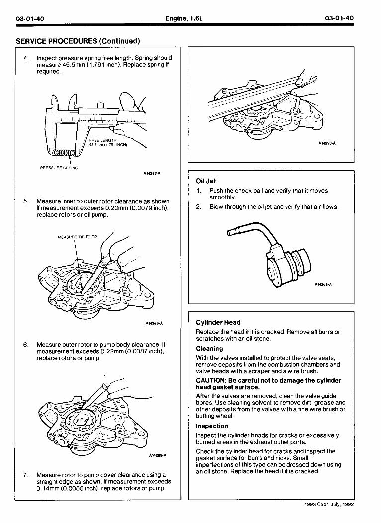
Inspect pressure spring free length. Spring should measure 45.5mm (1.791 inch). Replace spring if reauired.
FREE LENGT 45 5mm ( 1 731 INCH)
\ PRESSURE SPRING
AUl l lFA
Measure inner toouter rotor clearance as shown. If measurement exceeds 0.20mm (0.0079 inch), replace rotors or oil pump.
Measure outer rotor to pump body clearance. If measurement exceeds 0.22mm (0.0087 inch). replace rotors or pump.
Measure rotor to pump cover clearance using a straight edge as shown. If measurement exceeds 0.14mm (0.0055 inch), replace rotors or pump.
Oil Jet
1. Push the check ball and verify that it moves smoothly.
2. Blow through the oil jet and verify that air flows
Cylinder Head
Replace the head if it is cracked. Remove all burrs or scratches with an oil stone.
Cleaning
With the valves installed to protect the valve seats, remove deposits from the combustion chambers and valve heads with a scraper and a wire brush.
CAUTION: Be careful not t o damage the cylinder head gasket surface.
After the valves are removed, clean the valve guide bores. Use cleaning solvent to remove dirt, grease and other deposits from the valves with a fine wire brush or buffing wheel.
Inspection
Inspect the cylinder heads for cracks or excessively burned areas in the exhaust outlet ports.
Check the cylinder head for cracks and inspect the gasket surface for burrs and nicks. Small imperfections of this type can be dressed down using an oil stone. Replace the head if it is cracked.
1993Capri July. 199
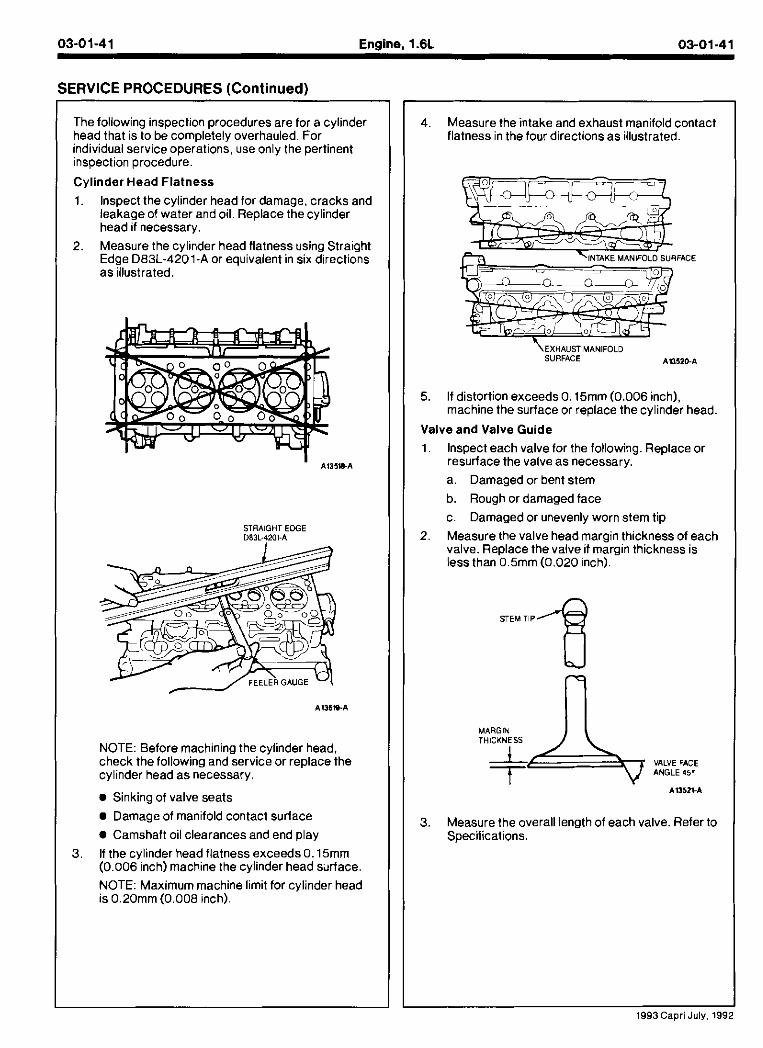
03-01-41 Engine. 1.6L 03-01-41
SERVICE PROCEDURES (Continued)
Tne follow ng mspect,on proced~res are for a cylinder neaa tnat 1s to be completely overnau ed For individual service operations, use only the pertinent inspection procedure.
Cylinder Head Flatness
Inspect the cylinder head for damage, cracks and leakage of water and oil. Replace the cylinder head if necessary.
Meas~re tne cy mder nead flatness sing Strafght Eaae D83L.4201-A or eaJ valent In SIX dlrect ons
STRAIGHT EDGE D83L-?201-A
NOTE: Before machining the cylinder head. check the following and service or replace the cylinder head as necessary.
Sinking of valve seats
Damage of manifold contact surface
Camshaft oil clearances and end play
If the cylinder head flatness exceeds 0.15mm (0.006 inch) machine the cylinder head sxface.
NOTE: Maximum machine limit for cylinder head is 0.20mm (0.008 inch).
4. Meas~re tne intake and exnaust man to d contact f atness n tne four d rectlons as ~dustratea.
\EXHAUST MANIFOLD SURFACE A1152&A
5. If distortion exceeds 0.15mm (0.006 inch), machine the surface or replace the cylinder head.
Valve and Valve Guide
1, Inspect each valve for the following. Replace or resurface the valve as necessary.
a. Damaged or bent stem
b. Rough or damaged face
c. Damaged or unevenly worn stem tip
2 Measure tne valve head margm thickness of each va ve Replace the valve 11 margln tnlckness IS .ess tnan 0 5mm (0 020 incn)
STEM TIP '8
3. Measure the overall length of each valve. Refer to Specifications.
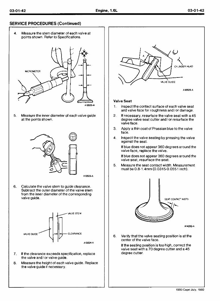
03-01-42 Engine, l.6L 03-01-42
SERVICE PROCEDURES (Continued)
4. Measure the stem diameter of each valve at points shown. Refer to Specifications.
Measure the inner diameter of each valve guide at the points shown.
Calculate the valve stem to guide clearance. Su~tract tne oder d ameterbf the va ve stem from the nner aiameter of the corresponding valve guide.
VALVE STEM
VALVE GUIDE CLEARANCE
A13524-A
If the clearance exceeds specification, replace the valve and/or valve guide.
Measure the height of each valve guide. Replace the valve guide if necessary.
CYLINDER HEAD
Valve Seat
Inspect the contact surface of each valve seat and valve face for roughness andlor damage.
If necessary, resurface the valve seat with a 45 aegree valve seat c A e r and or resurface the vake face
Apply a thin coat of Prussian blue to the valve face.
Inspect the valve seating by pressing the valve against the seat.
If blue does not appear 360 degrees around the valve face, replace the valve.
If blue does not appear 360 degrees around the valve seat, resurface the seat.
Measure the seat contact width. Measurement must be 0.8-1.4mm (0.0315-0.0551 inch).
Verify that the valve seating position is at the center of the valve face.
If the seatlng posltion s too h gn, correct the va ve seat w In a 70 degree c-tter and a 45 degree cutter.
1993Capri July, 199
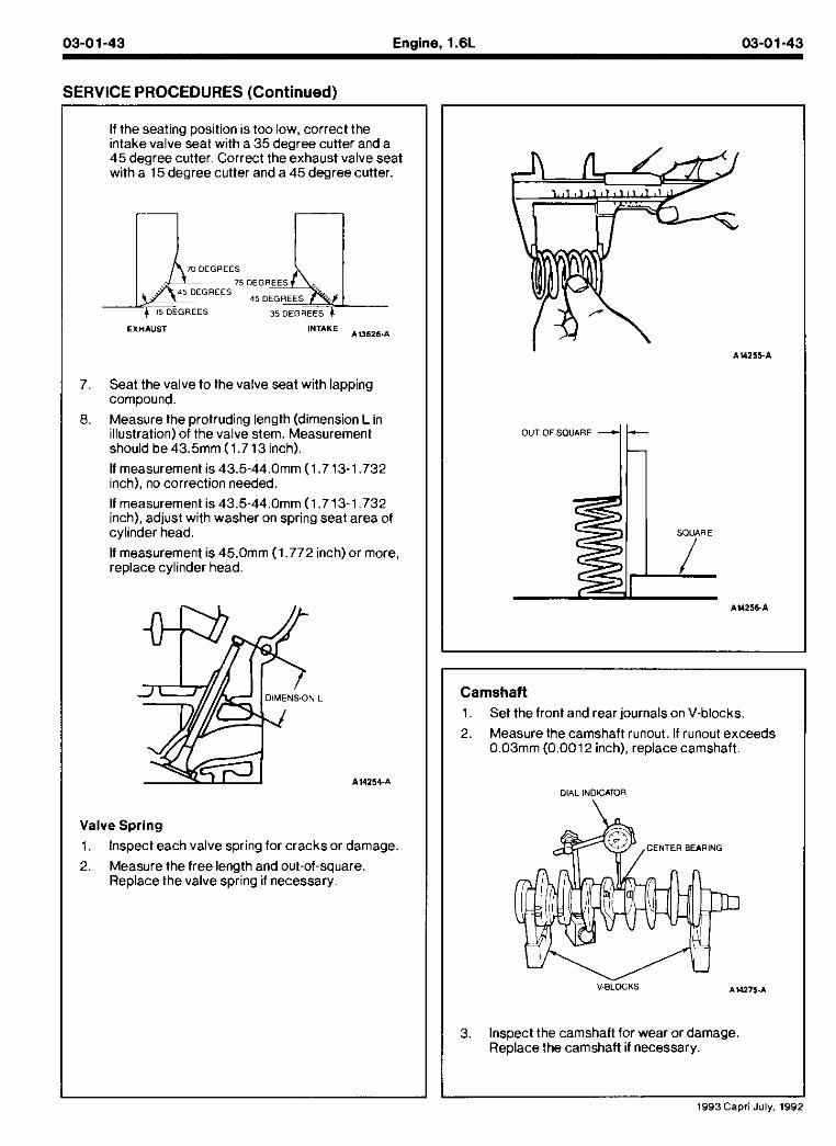
03-01-43 Enaine. l.6L 03-01-43
SERVICE PROCEDURES (Continued)
If the seating position is too low, correct the mtake va ve-seat w ~ l h a 35 degree cutler and a 45 degree cutler Correct the exhaust valve seal with a-15 degree cutter and a 45 degree cutter.
EXHAUST INTAKE A 0 6 2 6 4
7. Seat the valve to the valve seat with lapping compound.
8. Measure the protruding length (dimension L in illustration) of the valve stem. Measurement should be 43.5mm (1.7 13 inch).
If measurement is 43.5-44.0mm (1.713-1.732 inch), no correction needed.
If measurement is 43.5-44.0mm (1.713-1.732 inch), adjust with washer on spring seat area of cylinder head.
If measurement is 45.0mm (1.772 inch) or more. replace cylinder head.
Valve Spring
1. Inspect each valve spring for cracks or damage.
2 Measure the free lengtn and out-of-square Rep ace tne valve spr ng 11 necessary
OUT OF SQUARE 1h
Camshaft
Set the front and rear journals on V-blocks.
Measure the camshaft runout. If runout exceeds 0.03mm (0.0012 inch), replace camshaft.
DIAL INDICATOR
\
Inspect the camshaft for wear or damage Replace the camshaft if necessary.
1993Capri July. 19s
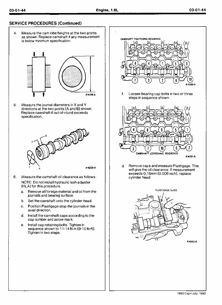
03-0 1-44 Engine, 1.6L 03-01-44
SERVICE PROCEDURES (Continued)
4. Measure the cam lobe heights at the two points as shown. Replace camshaft if any measurement is below minimum specification.
5. Measure the journal diameters in X and Y directions at the two points (A and B) shown. Replace camshaft if out-of-round exceeds specification.
6. Measure the camshaft oil clearance as follows:
NOTE: Do not install hydraulic lash adjuster (HLA) for this procedure.
a. Remove all foreign material and oil from the journals and bearing surface.
b. Set the camshaft onto the cylinder head.
c. Position Plastigage atop the journals in the axial direction.
d lnsla I me camshall caps accordmg lo the cap n,nber ana arrow marK.
e. Install cap retaining bolls. Xghten in sequence shown to 11-14 N m (9-10 Ib-ft) nghten in two steps.
f. Loosen bearing cap bolts in two or three steps in sequence shown.
g . Remove caps and measure Plastigage. This will give the oil clearance. If measurement exceeds 0.15mm (0.006 inch), replace cvlinder head.
PLASTIGAGE GUIDE
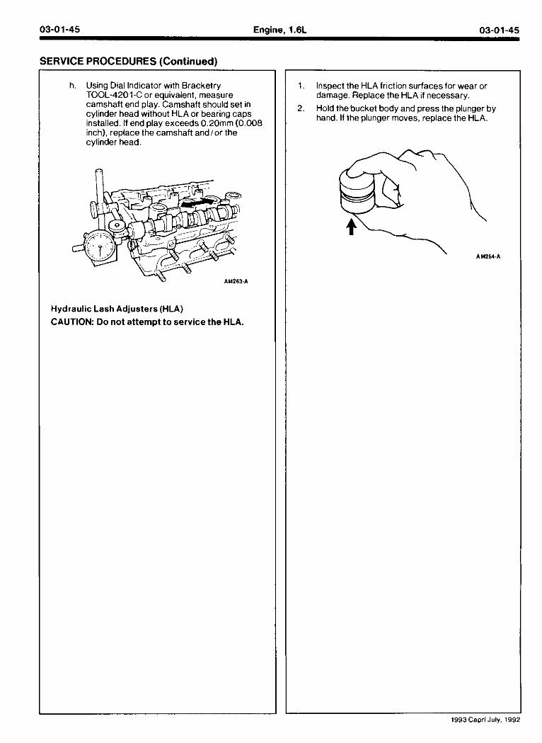
03-01-45 Engine, 1.6L 03-01-45
SERVICE PROCEDURES (Continued)
h. Using Dial Indicator with Bracketry TOOL-4201-C or equivalent, measure camshaft end play. Camshaft should set in cylinder head without HLA or bearing caps installed. If end play exceeds 0.20mm (0.008 inch), replace the camshaft andior the cylinder head.
Hydraulic Lash Adjusters (HLA)
CAUTION: Do not attempt t o service the HLA.
1. Inspect the HLA friction surfacesfor wear or damage. Replace the HLA if necessary.
2. Hold thebucket body and press the plunger by hand. If the plunger moves, replace the HLA.
1993Cspri July, 195
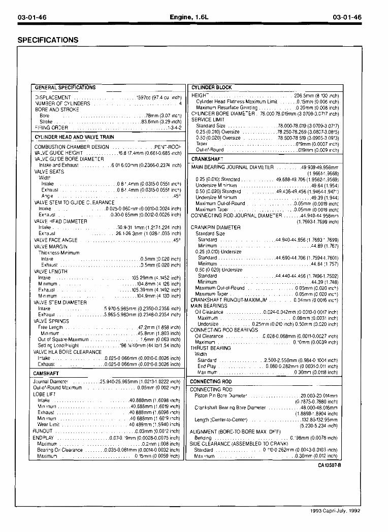
03-01-46 Engine, 1.6L 03-01-46
GENERAL SPECIFICATIONS -- -- -
DISPLACEMENT . . . . . . . . . . . 1597cc (97 4 cu inch) NUMBER OF CYLINDERS . . . . . . . . . . . . . . . . . 4 BORE AND STROKE
Bore . . . . . . . . . . . . . . . 78mm (3.07 inch) . . . . . . . . . . . Stroke 8 3 6 m m (3.29 (nth)
FRiNG ORDER . . . . . . . . . . . . . . . . . . . 1-3-4-2
CYLINDER HEAD AND VALVE TRAIN
COMBUSTION CHAMBER DESIGN PENT ROOF VALVE GUIDE HEIGHT $6 8 17 4mm 10 661 0 685 inch1 VALVE GUIDE BORE DIAMETER
Inlake and Exhaust . 6 01M 03mm (0.2366.0.2374 nch) VALVE SEATS
W~dth Intake . . . . . . . 0 814mm (0 0315-0 0551 ~nchl Exhausl . . . . . 0 8-1 4mm (0 0315-0.0551 inch) Anole . . . . . . . . . . . . . . . . . . . . . . . . . 4 s
V A L V ~ S T E M TO GUIDE CLEARANCE Intake 0 025 0 06Omrr tO 0010.0 0024 inch) Exhaust 0 30-0 65mm (0 0012 0 0026 inch)
VALVE HEAD DIAMETER Inlake . . . . . . . . 309.31 tmm (1.217-1.224 inch) Exhaust . 26.1-26 3mm (1 028-1 035 nch)
VALVE FACE ANGLE . . . . . . . . . . . . . . . . . . . 45O VALVE MARGIN
Thckness-Mmimum Intake . . . . . . . . . 0 5 m m (0.020 ~nch) Exhaust . . . . . . . . . . . . . .05mm 10.020 inch)
VALVE LENGTH Intake . . . . . . . . . . . 105 29mm (41452 nch) Mn~mum . . . . . . . 1048mm (4 126 nch) Exhaus1 . . . . . . 10539mm (4 1492 nch) Minmum . . . . . . . . 1049mm (4 130 nch)
VALVE STEM DIAMETER lnlake , . . , , . . 5 970-5985mm (0 2350-0.2356 inch)
. . . . . . . Exhaust 5 965.5 98Omm 10 2348-0.2354 lnchl VALVE SPRINGS
Free Length . . . 472mm (1 858 lnchl . . . . . . . . . . . . . Minmum 458mm (1.803 inch)
Out of Square-Maximum . . . . . . . . . . . . . 16mm (0 063 nch) Settlno LoadfHe~ohl . 196 N!40mm 144 Ib l l 54 nchl
.......... -'a*? 2C25.C C 6 i . l ~ C CC'C.: ((26 ncr
'xr I.S 0 (25.0 0 6 i w 1 ( X ' C C Y 2 6 i c r
CAMSHAFT
Journal D~ameter . 25.940-25965mm (1.0213-1 0222 nch) Out-ot-Round Maxmum . . . . . . . . . . . . 005mm 10 002 :nchJ LOBE LIFT
Intake . . . . . . . . . 40888mm il.6098 mcht Mnmum 40 688mm 11 6019 m h i Exhaust 40 888mm (1 6098 inch) Minmum 40 688mm (1 6019 inch) Wear L ~ m t 40 489mm (1 5940 inch)
ENDPLAY . . . . . . 0 0 7 0 l9mm (0.0028-0.0075 inch) Maxmum . . . . . 02mm ( 008 inch) Bear~ng 011 Clearance . 0.035-0081mm (0.0014-0 0032 inch) Max!mum . . . . . . . . . . . . . . 0 15mm (0 0059 inch)
CYLINDER BLOCK ~ ~~ - HEIGHT . . . . . . . . . . . . . . . 206 5mm (8 130 inch)
Cyltnder Head Flatness Max~mum Llmlt . 015mm (0 006 lnch) Max~mum Resurlace Gr~nd~ng . . . . . . . . . 0 20mm (0 008 inch)
CYLINDER BORE DIAMETER . 78000~78019mm (3 0709-3.0717 inch) SERVICE LIMIT
Standard Size . . . . . . . . . . . . 78000-78019 (3 0709-3.0717) 0.25 1O.OlOl Oversize . . . . . . . . . 78.250.78.269 13.0807.3.08151 0.50 io.020) Overs~ze . . . . . . . . 78 500-78 519 (3 0905~3.~913j Taper . . . . . . . . . . . . . . . . . . . . . . 019mm (0 0007 inch) Out-ol.Round . . . . . . . . . . . . . . . . . . 019mm (0.009 lnch)
CRANKSHAFT
MAIN BEARING JOURNAL DIAMETER 49 938-49 956mm 11 4661-1 466RI .....
0 25 (0.010) Standard . 49.688-49.706 (19562-1:9;69i Underslze M~nimum . . . . . . . . . . . . . . . 4964 (1.954) 0.50 (0.020) Standard . . . 49 438-49.456 (1,9464-19471)
. . . . . . . . . . . . . . . . . . Undersize Minimum 4 9 39 (1.944) Maximum Out-ol-Round . . . OO5mm 10.0019 lnchl Maximum Taper . . . . . . . . . . . . . . . . . 0 0 5 m m 10 0019 mch)
CONNECTING ROD JOURNAL DIAMETER . 44940.44 956mm (1.7693-1.7699 inch)
CRANKPIN DIAMETER Standard Size Slandard . . . . . . . . . . 4 4 940-44.956 (1 76931 7699) Minimum . . . . . . . . . . . . . . . . . . . 4 4 8 9 (1 767)
0.25 (0.010) Undersze Standard . . . . . . . . . . . . . . . . . 44.690-44 706 (1 7594-1.7601) Minimum . . . . . . 4 4 6 4 (1 757)
0.50 (0 020) Underslze Standard . . . . 4 4 440-44 456 (1 7496-1 7502) Mnimum . . . . . . . . . . . . 44.39 11.7481
~ , ~, Max~mum Ou!-of-Round . . . . . . . . . . . . . 0 05mm (0.020 inch) Maxlmum Taper . . . . . . . . . . . . . . . . . . . 0 0 5 m m (0.020 inch)
CRANI(SHAFT RUNOUT-MAXIMUM . 004mm !O 0016 inch) MAlN BEARINGS
011 Clearance . . . . . . . 0.024-OO42mm (0 0010-0 0017 inch) Maxmum . . . . . . . . . . OO8mm (0.0031 mch) Underslze . 025mm 10 010 inch) 0 50mm (0.020 inch)
CONNECTiNG ROD BEARINGS 011 Clearance . 0.028-0068mm (0.00t1-0,0027 lnchl Max~mum . . . . . . . . . . . . . . . . . 0 lOmm (0 0039 inch)
THRUST BEARING Wldlh
9 a r l a ' c 2 5C 2 55Cmm C 984 0 10:: r c - Er??,, " (80 C Y82m.l 0 0031 3 C ' r :-t
'Jar rr.r C 3Cnn ? 073 rrr
CONNECTING ROD -. ~p CONNECTING ROD
Piston P r Bore Dtameter . . . . . . . . . . . . . . . 20 003-20014mm (0 7875-0.7880 inch)
Crankshalt Bearng Bore D~ameter . . 4 8 000.48.016mm (1 8898-1 ,8904 inch)
Length (Center-to-CenlerJ . . . . . . . . . . . . . . 132.85-13295mrn 15.230-5 234 nchl
4LIGNMENT (BORE-TO~BORE MAX DIFF) Bendng . . . . . . . . . . . O198mm (0.0078 inch)
SIDE CLEARANCE (ASSEMBLED TO CRANK1 . . . . . . . . Standard 0 110-0262mm (0 0043-0.0103 nch) . . . . . . . . . . . . . . . . . Maxmum 0 3 0 m m (0.012 nch)
1993Capr i July. 199
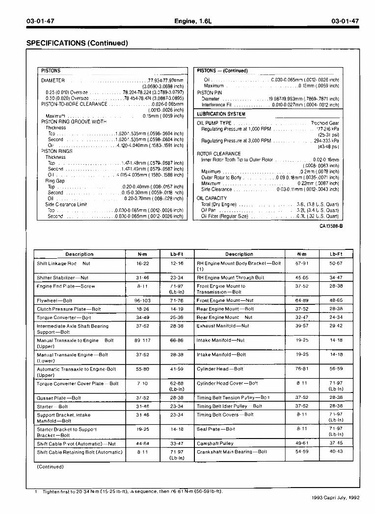
03-01-47 Engine, 1.6L 03-01-47
SPECIFICATIONS (Continued)
PISTONS
DIAMETER
(0010-0026 inch) Maxmum 0 15mm (0059 inch)
PISTON RING GROOVE WIDTH Th~ckness
PISTON RINGS Thickness Too . . . . . . . . . . . . . . . . . . . 147-1 49mm 10579-0587 inchi Sdcond . . . . . . . . . . . 1 47-1.49mm i 0579.0587 inchj Oil . . . . . . . . . . . . 4 015-4 035mm j 1580-1588 inch)
Rng Gap Top . . . . . . . . 020-040mm (008- 0157 inch) Second . . . . . . . . 0.15-0 30mm ( 0059-0118 inch) 0 1 1 . . . . . 0 20.0.70mm f 008-028 inch1
Side Clearance Llmlt
PISTONS -(Continued) --
Oil . 0.030-0 065mm (0012- 0026 inch) Max~mum . . . . ,015mm (0059 nchl
PISTON PIN D~ameter . 19 987-19993mm (7869-7871 nch) Interference Fll . . . . . . . . 0.010-0 027mm (0004- 0012 nch)
LUBRICATION SYSTEM
OIL PUMP TYPE . . . . . . . . . . . . . . . Trochold Gear Regulating Pressure at 1,000 RPM . . . . . . . . 177-216 kPa
125.31 Osii Regulating Pressure a13.000 RPM 294-333 kPa
(43-48 ps )
Inner Rotor Toolh Tip lo Outer Rolor . . . . . . . . . . . . . 002.0 16mm I n n m nnm
Maximum . . . . . . . . . . . . . . . . . 0 2mn (0078 nch) Outer Rotor la Body . 0 09-018mm j.0035- 0071 inch) Maximum . . . . . . . . . . . . 0 22mm 1.0087 mchi Side Clearance . . . . . . . . . . . . . 0 03-0 l lmm ( 0012-0043 inch)
OIL CAPACITY Total 1Drv Enolnei . . . . . . . . . . . . . 36L 13.8 U S Ouarll . , < ,
011 Pan . . . . . . . . . . . . . . . . . . . . . 3 2~ (3.4 u S. ouait j Oil Flller (Regular Size) . . . . . . . . . . 0 3 L (32 US. Quart)
(Continued)
1 Tiahten f ~ r s t t o 2 0 3 4 N.m (15-25 lb-It). ~nsequence. then 7 6 8 1 N.m (56-59 lb-ft). 1993Capri July. 1992
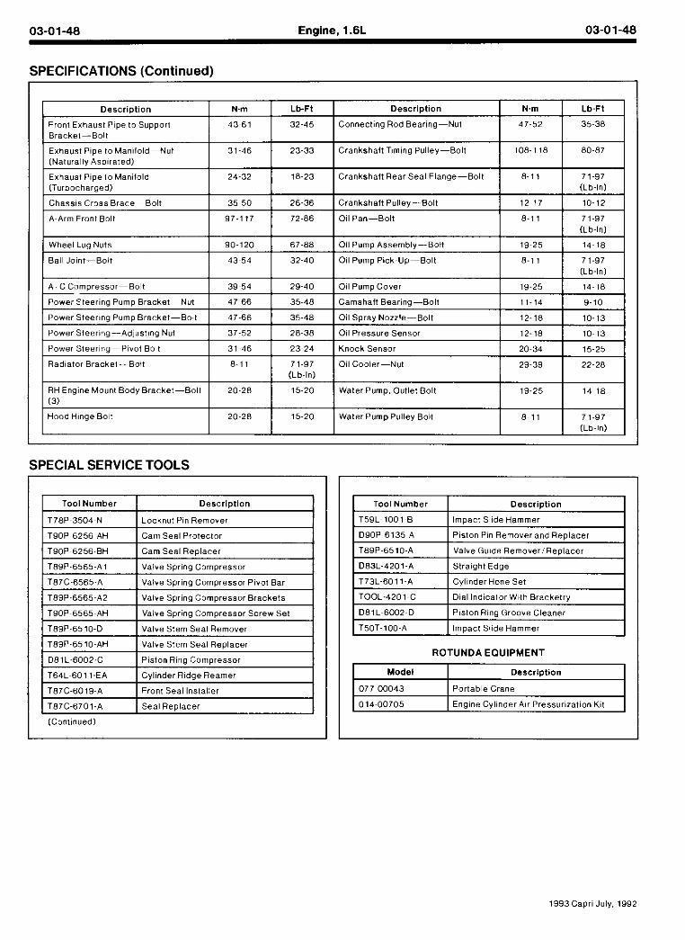
03-01-48 Engine, l.6L 03-01-48
SPECIFICATIONS (Continued)
Exhaust Pipe l o Manifold (Turbocharged)
Wheel Lug Nuts 90-120 1 67-88 1 Oil Pump Assembly-Bolt 1 9 ~ 2 5 1 4 ~ 1 8
Ball Jolnt-Bolt 32-40 Oil Pump Pick~Up-Bolt 1 8-11 71-97
N m
4 7 ~ 5 2
1 0 8 1 18
Descr ipt ion
Connecting Rod B e a m - N u t
Crankshaft Tlmlng Pulley-Bolt
Descr ipt ion
Front Exhaust P p e to Support Bracket-Boll
Exhaust Pipe l o Mamlold-Nut
Chassls Cross Brace-Bolt 1 3 5 5 0 1 26-36 1CrankshaftPulley-Bolt 1 2 ~ 1 7 10-12
SPECIAL SERVICE TOOLS
Lb-FI
3 5 ~ 3 8
8 0 ~ 8 7
24-32
A ~ A r m Front Bolt
N m
4 3 ~ 6 1
31-46
Lb-Ft
32-45
23-33
18-23
97-1 17
Tool Number
T 7 8 P ~ 3 5 0 4 ~ N
T 9 0 P ~ 6 2 5 6 ~ A H
T90P~6256-BH
T89P-6565-A1
T87C-6565-A
T89P-6565-A2
T 9 0 P ~ 6 5 6 5 ~ A H
T89P-6510-D
T89P-6510-AH
081L-6002-C
T64L~601 1-EA
T87C-6019-A
T87C-6701~A
Descr ipt ion
Locknut Pin Remover
Cam Seal Protector
Cam Seal Replacer
Valve Spring Compressor
Valve Spring Compressor Pivot Bar
Valve Spring Compressor Brackets
Valve Spring Compressor Screw Set
Valve Stem Seal Remover
Valve Stem Seal Replacer
Piston Ring Compressor
Cylinder Ridge Reamer
Front Seal Installer
Seal Replacer
Tool Number I Descr ipt ion
Crankshaft Rear Seal Flange-Bolt
72-86
(Continued)
T 5 9 L l 0 0 1 ~ B
DJOP e l 3 5 A I P 513" P n R e v .cr anc Rep acer
T50T-100-A I Impact Slide Hammer
ROTUNDA EQUIPMENT
Impact Slide Hammer
ToJP-c510.A
DR3-4201-A I Slra gnl E c j e
8 ~ 1 1
Oil Pan-Bolt
.a .el;. c . ~ Rerr2.w Rep arc!
T73.601 I-A
1 014-00705 I Enaine Cvl inderA~r Pressur~zation Kit I
7 1 ~ 9 7 (Lb-In)
C, n w r n m c Se*
Mode l I Description
1993Capri July, 1992
8-11
077~00043
71-97
Portable Crane


![1.6L 4-CYL - VIN [E] - TexasNissans.comtexasnissans.com/fsm/Sentra/1993/1.6l 4 cyl.pdf · 1.6L 4-CYL - VIN [E] 1993 Nissan Sentra 1993 NISSAN ENGINES 1.6L 4-Cylinder ... on timing](https://img.pdfslide.us/doc/110x75/5ae38e697f8b9a0d7d8dcc83/16l-4-cyl-vin-e-4-cylpdf16l-4-cyl-vin-e-1993-nissan-sentra-1993-nissan.jpg)