Embed Size (px)
Citation preview
SUMMARY OF WORK 01010-1
SECTION 01010
SUMMARY OF WORK PART 1 GENERAL
1.1 SECTION INCLUDES
Construct work as described in the Contract Documents.
Provide the materials, equipment, and incidentals required to make the project completely operable.
Provide the labor, equipment, tools, and consumable supplies required for a complete project.
Provide the civil, architectural, structural, mechanical, electrical, instrumentation, and all other work required for a complete and operable project.
Test and place the completed project in operation.
Plans and specifications may not indicate or describe all of the work required to complete the project. Additional details required for the correct installation of selected products are to be provided by the Contractor and coordinated with the Engineer.
1.2 RELATED SECTION
Section 16100 – Basic Materials and Methods for Electrical Installations.
1.3 JOB CONDITIONS
The General Conditions, the Supplementary Conditions, and Division One specifications apply to each of the other specification sections.
Comply with all applicable federal, state, and local codes and regulations pertaining to the nature and character of the work being performed.
1.4 DESCRIPTION OF WORK
Work is described in general, non-inclusive terms as:
Install a grease interceptor, septic tank, aerobic tank with compressor, lift station
with pumps, valve vault and storage tank.
Install all necessary electrical systems.
Install approximately 1375 linear feet of sanitary sewer force main by open cut including fittings and a manhole to tie into the existing sanitary sewer line on the north end.
SUMMARY OF WORK 01010-2
1.5 WORK BY OWNER
The Owner plans to perform the following items of work which are not included in this contract, but may impact construction scheduling, testing, and start up.
1. Relocation of the existing propane tank
Owner will perform work as required for the operation and maintenance of the existing facilities during construction, unless otherwise stated.
PART 2 PRODUCTS
Provide materials and products per the individual sections of the specifications. PART 3 EXECUTION
[Not Used]
END OF SECTION

JOB MANAGEMENT 01041-1
SECTION 01041
JOB MANAGEMENT PART 1 GENERAL
1.1 SECTION INCLUDES
Furnish equipment, manpower, products, and other items necessary to complete the project with an acceptable standard of quality and within the contract time. The project shall be constructed in accordance with current safety practices.
Manage the project site to allow access to site and control construction operations.
Provide labor, materials, equipment, and incidentals necessary to construct temporary facilities to provide and maintain control over environmental conditions at the job site including the removal of temporary facilities when no longer needed.
Temporary controls shall include the construction of temporary impounding works, channels, diversions, furnishing and operation of pumps, installing piping and fittings, and other construction for control of conditions at the site. Remove temporary controls at the end of the project.
1.2 RELATED SECTION
Section 02220 – Trench Safety.
1.3 POLLUTION CONTROL
Prevent the contamination of soil, water, or atmosphere by the discharge of noxious substances from construction operations. Provide adequate measures to prevent the creation of noxious air-borne pollutants. Prevent dispersal of pollutants into the atmosphere. The Contractor shall not dump or otherwise discharge noxious or harmful fluids into drains or sewers nor allow noxious liquids to contaminate public waterways in any manner.
Provide equipment and personnel and perform emergency measures necessary to contain any spillage.
1. Contain chemicals in protective areas and do not dump on soil.
2. If contamination of the soil does occur, excavate contaminated soil and dispose at an off-site location.
3. Provide documentation to the Owner which states the nature and strength of the contaminant, method of disposal, and the location of the disposal site.
4. Disposal of the contaminant is to comply with local, state, and federal regulations regarding the disposal of pollutants.
JOB MANAGEMENT 01041-2
5. Fill resulting excavations with suitable backfill and compact to the density of the surrounding undisturbed soil.
Groundwater or run-off water which has come into contact with noxious chemicals, sludge, or sludge-contaminated soil is considered contaminated.
1. Contaminated water must not be allowed to:
a. Enter streams or water courses.
b. Leave the site in a non-contained form.
c. Enter non-contaminated areas of the site.
2. Pump contaminated water to holding ponds constructed by the Contractor for this purpose or discharge to areas on the interior of the site as designated by the Engineer.
3. Construct temporary earthen dikes or take other precautions and measures as required to contain the contaminated water and pump to a designated storage area.
4. Any equipment used for handling contaminated water or soil within contaminated areas shall be washed with uncontaminated water prior to using such equipment in an uncontaminated area. Wash water used to wash such equipment is considered contaminated and shall be pumped to the designated confinement area.
1.4 EARTH CONTROL
Remove excess soil, spoil materials, and other earth not required for backfill at the time of generation. Control stock pile material to eliminate interference with construction and Owner's operations.
1.5 SAFETY REQUIREMENTS
Protect the safety and welfare of workmen on the project, the Owner, and the general public around the construction site. The Contractor is solely responsible for safety at the project site. Provide and maintain barricades, guard rails, covered walkways, and other protective devices to warn and protect from hazards at the construction site.
Trenches shall comply with the provisions of Section 02220 – Trench Safety.
Perform construction within buildings or structures occupied by the Owner per established fire codes and ordinances.
1.6 MAINTENANCE OF WATER
Manage water resulting from rains or ground water at the site. Maintain trenches and excavations free of water at all times. Provide and maintain pumps as necessary to remove excess water. Direct water away from the site to prevent damage to surrounding property.
JOB MANAGEMENT 01041-3
Perform operations necessary to control water at the site. Lower the water table in the construction area by acceptable means if necessary to maintain the site in a dry and workable condition at all times. Provide drains, sumps, casings, well points, and other water control devices as necessary to remove excess water.
Maintain standby equipment to provide proper and continuous operation for water management. Monitor the operation on a 24-hour basis to provide continuous operation.
Modify the water management plan as required by the Engineer. In the event of failure of the system, flooding of the excavation may be ordered by the Engineer until the system is returned to service.
Ensure that water drainage does not damage adjacent property.
The Contractor shall be responsible for the discharge of water from the site.
1.7 EXCESS EARTH
Dispose of earth removed from excavations that is not required for backfill or embankments. Remove excess earth from the site within a reasonable time after completing excavation work.
1.8 BLASTING
Blasting for excavations shall not be allowed.
PART 2 MATERIALS
[Not Used] PART 3 EXECUTION
[Not Used]
END OF SECTION
QUALITY CONTROL 01400-1
SECTION 01400
QUALITY CONTROL PART 1 GENERAL
1.1 SECTION INCLUDES
Furnish labor, materials, and equipment as required to demonstrate that the work conforms to the Contract Documents.
1.2 QUALITY ASSURANCE ACTIVITIES BY THE OWNER
Quality assurance activities of the Owner and Engineer through their own forces or through contracts with materials testing laboratories and survey crews are for the purpose of monitoring the results of the Contractor's work to see that it is in compliance with the requirements of the Contract Documents.
A. Testing performed by the Owner will be paid for by the Owner.
B. Quality assurance activities of the Owner and Engineer in no way relieve the Contractor of the obligation to perform work and furnish products and constructed work conforming to the Contract Documents.
C. Failure on the part of the Owner or Engineer to test products or constructed works in no way relieves the Contractor of the obligation to perform work and furnish materials conforming to the Contract Documents.
1.3 LIMITATION OF AUTHORITY OF THE TESTING LABORATORY
A. The testing laboratory representatives are limited to providing consultation on the test performed and in an advisory capacity.
B. The testing laboratory is not authorized to:
1. Alter the requirements of the Contract Documents.
2. Accept or reject any portion of the work.
3. Perform any of the duties of the Contractor.
4. Stop the work.
PART 2 PRODUCTS
Furnish testing apparatus and related accessories necessary to perform the tests.
QUALITY CONTROL 01400-2
PART 3 EXECUTION
3.1 PIPING SYSTEMS
A. TEST REQUIREMENTS
1. Perform tests on piping systems including piping installed between structures or connected to existing pipe.
2. Conduct tests on buried pipe to be hydrostatically tested after the trench is completely backfilled. If field conditions permit and if approved by the Engineer, partially backfill the trench and leave the joints open for inspection and conducting of the initial service leak test. Do not conduct the acceptance test until backfilling is complete.
3. Conduct the test on exposed piping after the piping is completely installed, including supports, hangers, and anchors, but prior to insulation.
4. Do not perform testing on pipe with concrete thrust blocking until the concrete has cured for at least five days.
5. Determine and remedy the cause of excessive leakage for any pipe failing to meet the specified requirements for water or air tightness.
6. Tests must be successfully completed and reports filed before piping is accepted.
7. Submit the plan for testing to the Engineer and Owner for review in accordance with the terms contained in the General Conditions and Division 01 Special Conditions.
8. Remove and dispose of temporary blocking material and equipment after completion and acceptance of the piping test.
9. Repair any damage to the pipe coating.
10. Clean pipelines so they are totally free flowing prior to final acceptance.
11. Test piping independently from tests on structures.
12. Test method and test pressure depend upon the application of the piping.
Pressure pipe is defined as piping that is part of a pumped or pressurized system. Perform testing for pressure pipe per the procedures indicated in paragraph B of this section.
Gravity pipe is defined as piping that depends upon the force of gravity for flow through the pipe, with the exception of process piping described in paragraph d. Perform testing for gravity pipe per the procedures indicated in paragraph C, D, or E of this section.
QUALITY CONTROL 01400-3
Process piping between hydraulic structures is to be considered as pressure pipe. Perform the test for this pipe per paragraph B of this section. The test pressure is to be the maximum hydrostatic head plus 10'. The maximum hydrostatic head is the difference in elevation of the pipe at its lowest point and the maximum top of wall elevation of the hydraulic structure on the piping system.
B. PRESSURE AND LEAKAGE TESTS OF PRESSURE PIPING
1. Perform hydrostatic pressure and leakage tests using methods and per performance requirements of AWWA C605.
The pressure required for the hydrostatic pressure test shall be 50 percent above the normal working pressure. If the normal working pressure cannot be determined, use the pipe pressure rating as the normal working pressure.
Provide temporary plugs and blocking necessary to maintain the required test pressure. Where piping is cast in the walls for a structure, brace the walls prior to testing as required to prevent load of test pressure from being imposed upon the structure.
Provide corporation cocks at least ¾ inch in diameter, pipe riser, and angle globe valves at each pipe dead-end in order to bleed air from the line.
The duration of the pressure test shall be at least two hours.
2. Perform a separate leakage test after the pressure test.
Perform the test at the maximum operating pressure as determined by the Engineer for a duration of not less than two hours.
Repair any visible leaks regardless of the total leakage shown by the test.
Repair pipelines which fail to meet the test and retest as necessary until the results conform to the test requirements.
Remove and replace defective materials, pipes, valves, and accessories.
Test the pipelines in sections by shutting valves or installing temporary plugs as necessary.
Fill the pipeline with water and remove the air.
Maintain the test pressure in the pipe for the entire test period by means of a force pump.
Accurately measure the water required to maintain the pressure. The amount of water required is a measure of the leakage.
QUALITY CONTROL 01400-4
The maximum allowable leakage is determined by the following formulas. PVC Pipes Q = LD(P)1/2 148,000
Q is the allowable quantity of makeup water in gallons per hour.
L is the length of pipe tested in feet. D is the nominal diameter of the pipe in inches. P is the test pressure in pounds per square inch gauge. Leakage is defined as the volume of water provided to maintain the test pressure after the pipe has been filled with water, the air expelled, and the pipe brought to test pressure.
3. Pipe with visible leaks or leakage exceeding the maximum allowable
leakage is considered defective and must be corrected.
C. TESTS FOR PLUMBING DRAINAGE AND VENT SYSTEMS
1. Plug openings as necessary.
2. Test drainage and venting systems by filling piping with water to the level of the highest vent stack for 30 minutes.
3. Make the examination for leakage at joints and connections.
4. There shall be no drop in water level.
3.2 MANHOLES AND WET WELLS
The Contractor shall be required to test each manhole and wet well installed as a part of this project prior to final acceptance of the project. The manholes and wet wells shall be tested independently of the sewer lines. Manholes and wet wells shall be tested using one of two methods.
A. If vacuum testing is to be performed, it shall be performed immediately after assembly and prior to backfill. If the manhole or wet well is to be tested after construction, the Contractor shall be required to excavate around the entire structure. Prior to testing, all lift holes and exterior joints shall be plugged with an approved non-shrink grout. No grout shall be placed in horizontal joints prior to testing. All pipes entering the structure shall be plugged, taking care to securely brace the plugs from being drawn into the structure. All stub-outs, boots and pipe plugs shall be secured to prevent movement while the vacuum is drawn. The test cover shall be secured to the top of the structure with a minimum 60 inch-pound torque wrench. The test head shall be placed at the inside of the top section and the seal inflated in accordance with the manufacturer’s recommendations. After the work described above has been performed, a vacuum of 10 inches of mercury shall be drawn and the vacuum pump shut off. With the valves closed, the time shall be measured for the vacuum to drop to 9 inches of mercury. The structure shall pass if the time is greater than 2 minutes.
QUALITY CONTROL 01400-5
If the structure fails the initial test, necessary repairs shall be made with a non-shrink grout while the vacuum is still being drawn. If the structure fails a second time, repairs should again be made and the structure shall be tested by means of a hydrostatic test which complies with the methods specified herein. If any structure fails the hydrostatic test, after failing the vacuum test twice, the Contractor shall consider replacing the structure. If the Contractor chooses to attempt to repair the structure, it must be retested by means of the hydrostatic test.
B. The second test method which the Contractor may use is a hydrostatic exfiltration test. If this test procedure is chosen by the Contractor, all pipe penetrations into the manhole or wet well shall be plugged and the structure filled with water. The maximum leakage for hydrostatic testing shall be 0.025 gallons per foot diameter per foot of depth per hour. If concrete structures are used, a wetting period of 24 hours will be allowed, with the structure being refilled at the end of the 24 hour period with the test beginning at that time. If a structure fails the exfiltration test, it shall be repaired and retested using the same procedure as outlined above.
C. All manhole and wet well tests shall be performed in the presence of the Engineer or his representative.
END OF SECTION
STORMWATER POLLUTION PREVENTION 01552-1
SECTION 01552
STORMWATER POLLUTION PREVENTION
PART 1 GENERAL
1.1 SECTION INCLUDES
The work to be performed under this section shall consist of furnishing all labor, equipment, and materials as required or necessary for storm water pollution prevention as shown in the plans and specified herein.
1.2 RELATED SECTIONS
A. Section 01568 – Erosion and Sediment Control During Construction
1.3 STORMWATER POLLUTION PREVENTION
The Contractor shall be solely responsible for insuring that erosion of the site is kept to a minimum.
In areas of cut and fill as well as along ditch lines, the Contractor shall perform temporary grading as necessary to insure that water is not concentrated in one area in a manner which could cause significant erosion.
If necessary in the opinion of the Engineer, the Contractor will be required to install erosion and sediment control measures to prevent the loss of soil from the site and siltation of the pipes and channels downstream from the project due to construction. Refer to the plans and Section 01568 – Erosion and Sediment Control During Construction.
In addition to the above-mentioned items, the Contractor shall also comply with any and all applicable federal, state, and local regulations relating to water quality and stormwater runoff including, but not limited to, the TCEQ TPDES stormwater regulations.
Any permits required for the construction site under the above referenced regulations shall be obtained by the Contractor. All responsibilities related thereto shall be placed upon the Contractor. All costs for erosion and sedimentation control (including fees) shall be included in the bid amount.
PART 2 PRODUCTS
[Not Used]
PART 3 EXECUTION
[Not Used]
END OF SECTION
EROSION AND SEDIMENT CONTROL DURING CONSTRUCTION 01568-1
SECTION 01568
EROSION AND SEDIMENT CONTROL DURING CONSTRUCTION PART 1 GENERAL
1.1 SECTION INCLUDES
A. Furnish labor, materials, equipment, and incidentals necessary to provide erosion and sediment control for the duration of the construction period including furnishing, installing, and maintaining erosion and sediment control structures and procedures and the proper removal when no longer required.
B. The intent of this specification is to provide guidelines for the Contractor to adhere to all state, federal, and local environmental regulations. It is also the intent to provide preventive measures to keep sediment from entering any storm water system including open channels. It is the Contractor's responsibility to adhere to all federal, state, and local requirements. While the Engineer may require the Contractor to install erosion control devices during construction, this will in no way relieve the Contractor of his responsibility.
1.2 SUBMITTALS
A. Submittals shall be in accordance with General Conditions and Division 01 Special Conditions of the contract. Data describing all materials incorporated into the project is required for all of the various erosion and sediment control devices. Manufacturers’ product data sheets shall be provided for manufactured products.
1.3 QUALITY ASSURANCE
A. Comply with applicable requirements of all governing authorities having jurisdiction. The specifications and the plans are not represented as being comprehensive, but rather convey the intent to provide complete slope protection and erosion control for both the Owner’s and adjacent property.
B. Erosion control measures shall be established at the beginning of construction and maintained during the entire length of construction. On-site areas which are subject to severe erosion and off-site areas which are especially vulnerable to damage from erosion and/or sedimentation are to be identified and receive additional erosion control measures as directed by the Owner, Engineer, or Project Representative.
C. All land-disturbing activities shall be planned and conducted to minimize the size of the area to be exposed at any one time, to minimize the time of exposure, and to minimize off-site sedimentation damage.
D. Surface water runoff originating upgrade of exposed area shall be controlled to reduce erosion and sediment loss during the period of exposure.
E. When the increase in the peak rates and velocity of storm water runoff resulting from a land-disturbing activity is sufficient to cause accelerated erosion of the
EROSION AND SEDIMENT CONTROL DURING CONSTRUCTION 01568-2
receiving ditch or stream, the Contractor shall install measures to control both the velocity and rate of release so as to minimize accelerated erosion and increased sedimentation of the stream as directed by the Owner, Engineer, or Project Representative.
F. The Contractor shall be responsible for periodically cleaning out and disposing of all sediment once the storage capacity of the drainage feature or structure receiving the sediment is reduced by one-half unless otherwise specified. The Contractor shall also be responsible for cleaning out and disposing of all sediment at the time of completion of the project.
G. Inspect all erosion and sediment control measures after each rainfall or daily during periods of prolonged rainfall. Inspection shall occur at least once a week during rainless periods. Correct any erosion and sediment control measures that do not conform to specifications and details.
1.4 JOB CONDITIONS
A. Comply with the local, state, and federal codes and ordinances. If the codes and ordinances require more stringent or additional erosion and sediment control measures during construction than those specified or shown on the plans, the Contractor shall provide such measures.
PART 2 PRODUCTS
2.1 STRAW BALES
A. Straw bales shall weigh a minimum of fifty pounds and shall be at least thirty inches in length. Bales shall be composed entirely of vegetable matter and be free of seeds. Binding shall be either wire or nylon string. Jute or cotton binding is unacceptable. Bales shall be used for no more than three months before being replaced. However, if weather conditions cause biological degradation of the straw bales, they shall be replaced sooner than the three month time period to prevent a loss of structural integrity of the straw bale dike.
2.2 SILT FENCE
A. Provide woven geotextile filter fabric made of either polypropylene, polyethylene, ethylene, or polyamide material. Geotextile fabric shall have a grab strength of 100 psi in any principle direction (ASTM D4632), Mullen burst strength exceeding 200 psi (ASTM D3786), and the equivalent opening size of between 20 and 50. Silt fence material shall contain ultraviolet ray inhibitors and stabilizers to provide a minimum of six months of expected usable construction life at a temperature range of 0° F to 120° F. Silt fence shall have galvanized welded wire mesh (12.5 gauge minimum, two inch by four inch maximum opening) as backing to provide support. Silt fence posts shall be1.00 – 1.33 lb/linear foot steel posts.
2.3 SANDBAGS
A. Sandbag material shall be polypropylene, polyethylene, polyamide, or cotton burlap woven fabric with a minimum unit weight of four ounces per square yard, a Mullen burst strength exceeding 300 psi, and ultraviolet stability exceeding 70
EROSION AND SEDIMENT CONTROL DURING CONSTRUCTION 01568-3
percent. Length shall be 24 to 30 inches. Width shall be 16 to 18 inches. Thickness shall be six to eight inches. Filled sandbags shall have an approximate weight of 90 to 125 pounds. Sandbags shall be filled with coarse grade sand that is free from deleterious material. All sand shall pass through a No. 10 sieve.
2.4 PVC PIPE
A. Pipe shall be SDR-35 polyvinyl chloride having a minimum nominal diameter of four inches. Pipes shall be sized for anticipated flows in a two-year return period storm.
2.5 SOIL RETENTION BLANKET
A. Soil retention blankets shall consist of a geocomposite of excelsior or fiber blanket with an extruded plastic net. The plastic net shall be photodegradable and the excelsior or fiber blanket shall be made smolder resistant without the use of chemicals. Soil retention blankets shall be high velocity type to resist severe runoff. Soil retention blankets shall be American Excelsior Company Curlex Blanket or Engineer approved equal.
2.6 ROCK FILTER DAM
A. All aggregate used for the construction of rock filter dams shall be hard, durable, clean, open-graded, and shall naturally resist crumbling, flaking, and eroding. Aggregate gradation shall be three to six inches for rock filter dams Types 1 and 2 and shall be four to eight inches for Type 3.
B. The galvanized steel wire mesh for Types 2 and 3 rock filter dams shall be a minimum 20 gauge and have 1” diameter hexagonal openings unless specified otherwise on the plans. Tie wires shall be a minimum 20 gauge.
2.7 STABLIZED CONSTRUCTION EXIT
A. Aggregate used in stabilized construction exits shall be hard, durable, clean, open-graded, angular, and have a nominal diameter of four inches.
PART 3 EXECUTION
3.1 INSTALLATION
A. STRAW BALE DIKE
Straw bales shall be embedded a minimum of four inches and securely anchored using 2" x 2" wood stakes driven through the bales into the ground a minimum of six inches. Straw bales are to be placed directly adjacent to one another leaving no gap between them.
Bales shall be placed in a single row lengthwise on proposed line with the ends of adjacent bales tightly abutting one another. In swales and ditches, the barrier shall extend to such a length that the bottoms of the end bales are higher in elevation than the top of the lowest middle bale.
EROSION AND SEDIMENT CONTROL DURING CONSTRUCTION 01568-4
Additional bales shall be placed behind the first row where the bales abut each other. The additional bales are used to prevent unfiltered runoff from escaping between the bales.
The excavated soil shall be backfilled against the barrier. Backfill shall conform to ground level on the downhill side and shall be built up to 4 inches above ground level on the uphill side. Loose straw shall be scattered over the area immediately uphill from a straw bale dike.
B. SILT FENCE
Provide silt fence systems at locations specified in accordance with the drawings and as necessary to prevent sediment from leaving the site. Silt fence shall be installed in such a manner that surface runoff will percolate through the system in sheet flow fashion and allow sediment to be retained and accumulated.
Silt fence should not be used where there is a concentration of water in a channel or drainage way or where soil conditions prevent a minimum toe-in depth of six inches or installation of support posts to a depth of 12 inches. If concentrated flow occurs after installation, corrective action must be taken such as placing a rock filter dam in the areas of concentrated flow.
Attach the fabric and wire backing to steel posts spaced no more than six feet apart and embedded at least 18 inches deep. Steel posts shall have projections for fastening wire and/or fabric.
Trench in the toe of the filter fabric fence with a spade or mechanical trencher so that the downstream face of the trench is vertical. The trench shall be a minimum of six inches wide and six inches deep. Lay filter fabric and wire along the bottom and downstream wall of the trench. Backfill and compact the trench.
The filter fabric and wire backing should be provided in continuous rolls and cut to the length of the silt fence to minimize the use of joints. When joints are necessary, the fabric and wire should only be spliced together at a support post and have at least six inches of overlap. The joint shall be securely sealed.
Unless otherwise directed, maintain the silt fence until the project is accepted by the Owner. Remove promptly in an appropriate manner when directed by the Owner.
Remove and dispose of sediment deposits off-site. Off-site disposal will be the responsibility of the Contractor. Sediment shall not be allowed to flush into streams or drainage ways. If sediment has been contaminated, it shall be disposed of in accordance with local, state, and federal regulations.
Inspection of silt fences shall occur after each rainfall or daily during periods of prolonged rainfall. Inspection shall occur at least once a week
EROSION AND SEDIMENT CONTROL DURING CONSTRUCTION 01568-5
during dry periods. Repair or replace damaged sections immediately to bring the silt fence back into compliance with the plans and specifications. Sediment deposits shall be removed when they reach one-third of the height of the fence.
C. SANDBAG BERM
The purpose of a sandbag berm is to intercept sediment-laden water from disturbed areas such as construction in steam beds, create a detention pond, detain sediment, and release water in sheet flow.
A temporary sandbag berm shall be installed across a channel or right of way in a disturbed area and should be used when the contributing drainage area is greater than 5 acres. The berm shall be a minimum height of 18 inches measured from the top of the existing ground at the upslope toe to the top of the berm. The berm shall be sized to have a minimum width of 48 inches measured at the bottom of the berm and 18 inches measured at the top of the berm.
The sandbag berm shall be inspected after each rain or daily during periods of prolonged rainfall. The sandbags shall be reshaped or replaced as needed. Additional inspections shall be made weekly during dry periods. When the silt depth reaches six inches, the accumulated silt shall be removed and disposed of at an approved site in a manner that will not contribute to additional sedimentation. The sandbag berm shall be left in place until all upstream areas are stabilized and accumulated silt is removed.
D. SOIL RETENTION BLANKET
A soil retention blanket is a geotextile or biodegradable fabric placed over disturbed areas to limit the effects of erosion due to rainfall impact and runoff across barren soil. Soil retention blankets are manufactured by a wide variety of vendors addressing a wide variety of conditions such as vegetation establishment and high velocity flow. Blankets are used in areas which are difficult to stabilize such as steep slopes, drainage swales, or high pedestrian traffic areas.
The soil retention blanket, whether installed as slope protection or as flexible channel liner, shall be placed within 24 hours after seeding or sodding operations have been completed or as approved by the Engineer. Prior to placing the blanket, the area to be covered shall be relatively free of all rocks or clods over 1-1/2 inches in maximum dimension and all sticks or other foreign material which will prevent the close contact of the blanket with the soil. The area shall be smooth and free of ruts, and other depressions. If, as a result of rain, the prepared bed becomes crusted or eroded or if any eroded places, ruts, or depressions exist for any reason, the Contractor shall be required to rework the soil until it is smooth and to reseed or resod the area at the Contractor's expense.
EROSION AND SEDIMENT CONTROL DURING CONSTRUCTION 01568-6
Installation and anchorage of the soil retention blanket shall be in accordance with the manufacturer's recommendations.
E. INTERCEPTOR DIKE
Install interceptor dikes at locations shown on the plans in accordance with applicable details and specifications.
Unless otherwise indicated, maintain a minimum dike height of 18 inches measured from the ground at the upslope toe to the top of the dike.
Flow from dikes shall be diverted to sediment trapping devices of the types and at locations shown on the plans. The grades for dikes shall provide positive drainage to the outlet.
F. ROCK FILTER DAMS
Trees, brush, stumps, and other objectionable material shall be removed and disposed of as necessary so as not to interfere with the construction of the filter dams.
The filter dams shall be constructed according to the following criteria unless otherwise shown on the plans:
Type 1 (non-reinforced).
Height 18 inches minimum measured vertically from existing ground to top of filter dam.
Top Width 2 feet minimum.
Slopes 2:1 maximum.
Type 2 (reinforced).
Height 18 inches minimum measured vertically from existing ground to top of filter dam.
Top Width 2 feet minimum.
Slopes 2:1 maximum.
The aggregate shall be placed on the galvanized wire mesh to the lines, height, and slopes specified without resulting in undue voids and to the satisfaction of the Engineer. The mesh shall be folded at the upstream side over the aggregate and secured to itself on the downstream side. The mesh shall be attached to itself with wire ties, hog rings, or as directed by the Engineer.
Type 3 (reinforced).
Height - 36 inches minimum measured vertically from existing ground to top of filter dam.
EROSION AND SEDIMENT CONTROL DURING CONSTRUCTION 01568-7
Top Width 2 feet minimum.
Slopes 2:1 maximum.
The aggregate shall be placed on the galvanized wire mesh to the lines, height, and slopes specified without resulting in undue voids and to the satisfaction of the Engineer. The mesh shall be folded at the upstream side over the aggregate and secured to itself on the downstream side. The mesh shall be attached to itself with wire ties, hog rings, or as directed by the Engineer.
The area upstream from the filter dams shall be maintained in a condition which will allow sediment to be removed following the runoff of a rainfall event. When the silt reaches a depth equal to 1/3 the height of the dam or one foot, whichever is less, the Contractor shall remove the accumulated sediment and dispose of it at an approved site in a manner that will not contribute to additional sedimentation. The filter dams shall be reshaped as needed and as directed by the Engineer.
The filter dams shall be maintained in place until all upstream areas are adequately stabilized. The area beneath the filter dams and area damaged by the removal process shall then be stabilized by the Contractor using appropriate methods as approved by the Engineer.
G. STABILIZED CONSTRUCTION EXIT
The Contractor shall provide stabilized construction exits at the locations shown on the plans and as necessary to prevent vehicles leaving the site from tracking sediment off-site.
Stabilized construction exits shall be a minimum of 50 feet long, 14 feet wide, and eight inches thick. The Contractor shall enlarge stabilized construction exits at his own expense if necessary to prevent off-site tracking of sediment.
The Contractor shall periodically add rock as necessary for the stabilized construction exit to continue to function as intended.
The stabilized construction exit and the surrounding area shall be graded as necessary to route runoff from these areas to other erosion and sedimentation controls.
H. PROTECTION OF BARE AREAS
Apply seeding and soil retention blanket to bare areas including new embankment areas, fills, stripped areas, graded areas, or otherwise disturbed areas which have a grade greater than five percent or which will be exposed for more than 30 days. Seeding shall be in accordance with section 02270 – Seeding for Erosion Control.
Bare working areas on which it is not practical or desirable to install seeding and soil retention blankets, as determined by the Engineer, such
EROSION AND SEDIMENT CONTROL DURING CONSTRUCTION 01568-8
as areas under proposed building slabs, shall be temporarily sloped to drain at a minimum of 0.2 percent and a maximum of five percent. These areas shall then be "trackwalked" with a crawler dozer traveling up and down the slope to form the effect of small "terraces" with the tracks of the dozer. Cover each area a minimum of three times.
Route runoff from the areas through the appropriate erosion and sediment control structures.
Protect earth spoil areas by "trackwalking" and silt fences.
When topsoil is called for as a component of another item, conduct erosion control practices described in this item during the topsoiling operation.
When topsoiling, maintain erosion and sediment control structures such as swales, grade stabilization structures, berms, dikes, waterways, and sediment basins.
Maintain grades that have been previously established on areas to be topsoiled.
After the areas to be topsoiled have been brought to grade, and immediately prior to dumping and spreading the topsoil, the subgrade shall be loosened by disking or by scarifying to a depth of at least two inches to permit bonding of the topsoil to the subsoil. Compact soil by passing a bulldozer up and down the slope, tracking over the entire surface area of the slope to create small “terraces”.
Dust Control
Control dust blowing and movement on construction sites and roads to prevent exposure of soil surfaces, to reduce on-site and off-site damage, to prevent health hazards, and to improve traffic safety.
Control dust blowing by utilizing one or more of the following methods.
Establishment of temporary vegetative cover.
Tillage to roughen surface and bring clods to the surface.
Irrigation by water sprinkling.
Utilization of barriers such as solid board fences, snow fences, burlap fences, crate walls, bales of hay, or similar materials.
Dust control methods shall be implemented immediately whenever dust is observed blowing over the project site.
EROSION AND SEDIMENT CONTROL DURING CONSTRUCTION 01568-9
I. LOCATION OF EROSION AND SEDIMENT CONTROL STRUCTURES
Locate erosion and sediment control structures as shown on the plans and as required to prevent erosion and removal of sediment from the project site. Silt fences shall be required for disturbed areas and soil stockpiles/spoil areas. The runoff from no more than one acre of area shall be routed through any individual silt fence installation.
Install diversion dikes to divert runoff to other erosion and sediment control structures.
Install silt traps at the inlet (upstream) end of drainage structures, including open channels, through which runoff from disturbed areas or soil stockpiles/spoil areas may drain.
Provide an overall erosion and sediment control system which protects disturbed areas and soil stockpiles/spoil areas. The system shall be modified by the Contractor as needed to effectively control erosion and sediment during construction.
3.2 MAINTENANCE
A. Maintain erosion and sediment control structures and procedures in full working order at all times during construction. This shall include any necessary repair or replacement of items which have become damaged or ineffective. Remove sediment on a regular basis which accumulates in sediment control devices and place the material in approved earth spoil areas, return the material to the area from which it eroded, or dispose of it off-site.
B. The Contractor shall prohibit all equipment and vehicles from maneuvering in areas outside the dedicated rights-of-way and easements for construction. Damage caused by construction traffic to erosion and sedimentation control systems shall be repaired immediately at the expense of the Contractor.
C. Upon completion of construction and stabilization of disturbed areas, properly remove the temporary erosion and sediment control structures and complete the area as indicated.
D. Soil retention blankets will not require removal if installed on a finished graded area specified to receive seeding.
3.3 FIELD QUALITY CONTROL
A. In the event of conflict between these requirements and storm water pollution control laws, rules, or regulations of federal, state, or local agencies, the more restrictive requirements shall apply.
END OF SECTION
SOIL MATERIALS 02205-1
SECTION 02205
SOIL MATERIALS
PART 1 GENERAL
1.1 SECTION INCLUDES
A. Subsoil materials.
B. Topsoil materials.
1.2 RELATED SECTIONS
A. Section 01400 – Quality Control.
B. Section 02207 – Aggregate Materials.
C. Section 02225 – Excavation, Backfill, and Compaction for Utilities.
1.3 REFERENCES
A. ASTM D698 – Standard Test Methods for Laboratory Compaction Characteristics of Soil Using Stand Effort
B. ASTM D2487 – Standard Classification of Soils for Engineering Purposes.
C. ASTM D2922 – Standard Test Methods for Density of Soil and Soil-Aggregate in Place by Nuclear Methods (Shallow Depth).
D. ASTM D3017 – Standard Test Method for Water Content of Soil and Rock in Place by Nuclear Methods (Shallow Depth).
1.4 QUALITY ASSURANCE
Perform the work in accordance with plans, specifications, and the Owner’s standards.
1.5 SUBMITTALS
A. Submit sources of materials.
B. Submit sieve analysis of each material to be used if requested by the Engineer.
C. Submit a 10 lb. Sample of each material to the testing laboratory in an airtight container if requested by the Engineer.
SOIL MATERIALS 02205-2
PART 2 PRODUCTS
2.1 SOIL MATERIALS
A. Soil Type S1 – Subgrade
1. Subgrade material is material remaining in place after excavation.
2. Subgrade material shall be suitable for pipe subgrade. It shall be undisturbed.
3. Where subgrade soils are soft, loose, or otherwise unsatisfactory, the soil shall be removed and replaced with Aggregate Type A5 – Flexible Base. Areas to be replaces shall be as determined by the Engineer.
B. Soil Type S2 – Type 1 Common Fill
1. Type 1 common fill shall be excavated and re-used material or borrow material approved by the Engineer.
2. Type 1 common fill shall be graded free of lumps larger than three inches, rocks larger than two inches, excessive silts, and debris.
3. Do not use soil containing brush, roots, or similar organic matter.
4. Type 1 common fill shall conform to ASTM D2487 Class II or Class III soils with a liquid limit less than 40 and a plasticity index less than 20 but greater than four.
C. Soil Type S3 – Type 2 Common Fill
Type 2 common fill shall be the same as Type 1 common fill except that it shall have no lumps or rocks greater than ¾ of an inch.
D. Soil Type S4 – Select Fill
1. Select fill shall be imported borrow material from a borrow area approved by the Engineer. If requested by the Engineer, material shall be tested for compliance by the Contractor and test results submitted to the Engineer for approval. The first test on the material requested by the Owner shall be paid for by the Owner. Re-tests required because the material did not meet this specification or because of a change in the source of the material shall be paid for by the Contractor.
2. Select fill shall be clayey sand soils free from organic matter with no lumps larger than one inch, no rocks larger than ½ inch, and no excessive silts.
3. Do not use soils containing brush, roots, sod, or other organic materials.
4. Select fill shall conform to ASTM D2487 Class II or Class III and shall have a liquid limit less than 45 with a plasticity index less than 15.
SOIL MATERIALS 02205-3
E. Soil Type S5 – Topsoil
1. Topsoil shall be soil suitable for growth of surface cover. Material shall be stripped and stockpiled from the site or borrowed from off-site.
2. Topsoil shall be free from roots, brush, rocks, and other extraneous matter exceeding one inch in any direction. Topsoil shall be free from weeds.
3. Topsoil shall be minimum 60% sand, maximum 30% silts, maximum 10% clay, and no less than 6% and no more than 20% organic matter.
4. If requested by the Engineer, submit test data showing compliance with this specification. Include percent weight of constituent material, material particle size, and pH.
2.2 SOURCE QUALITY CONTROL
A. Refer to Section 01400 – Quality Control.
B. Perform testing and analysis of material in accordance with ASTM D698.
C. If tests indicate materials do not meet specified requirements, change material and retest.
D. Provide materials of each type from one source throughout the project. A change in source requires sampling and testing at the Contractor’s expense and approval by the Engineer.
PART 3 EXECUTION
3.1 SOIL REMOVAL
A. Excavate soils from areas designated.
B. Remove lumped soil, boulders, and rock.
C. Excess material not intended for reuse shall be removed from the site.
3.2 STOCKPILING
A. Stockpile materials on site at locations designated by the Engineer.
B. Stockpile in sufficient quantities to meet project schedule and requirements.
C. Separate differing materials with dividers or stockpile apart to prevent mixing.
D. Prevent intermixing and contamination of soil types.
E. Direct surface water away from the stockpile site to prevent erosion or deterioration of materials.
SOIL MATERIALS 02205-4
3.3 STOCKPILE CLEANUP
A. Remove the stockpile and leave the area in a clean and neat condition. Grade site surface to prevent freestanding surface water.
B. If a borrow area is indicated, leave the area in a clean and neat condition. Grade site surface to prevent freestanding surface water.
END OF SECTION
AGGREGATE MATERIALS 02207-1
SECTION 02207
AGGREGATE MATERIALS
PART 1 GENERAL
1.1 SECTION INCLUDES
Aggregate materials.
1.2 RELATED SECTIONS
A. Section 01400 – Quality Control.
B. Section 02205 – Soil Materials.
C. Section 02225 – Excavation, Backfill, and Compaction for Utilities.
1.3 REFERENCES
A. ASTM C33 – Standard Specifications for Concrete Aggregates.
B. ASTM C136 – Standard Test Method for Sieve Analysis of Fine and Coarse Aggregates.
C. ASTM D698 – Standard Test Methods for Laboratory Compaction Characteristics of Soil Using Stand Effort.
D. ASTM D2487 – Standard Classification of Soils for Engineering Purposes.
E. ASTM D2922 –Standard Test Methods for Density of Soil and Soil-Aggregate in Place by Nuclear Methods (Shallow Depth).
F. ASTM D3017 – Standard Test Method for Water Content of Soil and Rock in Place by Nuclear Methods (Shallow Depth).
G. ASTM D4318 – Standard Test Methods for Liquid Limit, Plastic Limit, and Plasticity Index of Soils.
H. Texas Department of Transportation – Standard Specifications for Construction of Highways, Streets, and Bridges.
1.4 SUBMITTALS
A. Submit sources of materials.
B. Submit a sieve analysis of each material to be used if requested by the Engineer.
C. Submit a 10 lb. sample of each material to the testing laboratory in an airtight container if requested by the Engineer.
AGGREGATE MATERIALS 02207-2
1.5 QUALITY ASSURANCE
Perform work in accordance with plans, specifications, and the Owner’s standards.
PART 2 PRODUCTS
2.1 COARSE AGGREGATE MATERIALS
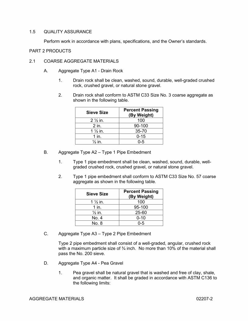
A. Aggregate Type A1 - Drain Rock
1. Drain rock shall be clean, washed, sound, durable, well-graded crushed rock, crushed gravel, or natural stone gravel.
2. Drain rock shall conform to ASTM C33 Size No. 3 coarse aggregate as shown in the following table.
Sieve Size Percent Passing (By Weight)
2 ½ in. 100 2 in. 90-100
1 ½ in. 35-70 1 in. 0-15 ½ in. 0-5
B. Aggregate Type A2 – Type 1 Pipe Embedment
1. Type 1 pipe embedment shall be clean, washed, sound, durable, well-graded crushed rock, crushed gravel, or natural stone gravel.
2. Type 1 pipe embedment shall conform to ASTM C33 Size No. 57 coarse aggregate as shown in the following table.
Sieve Size Percent Passing (By Weight)
1 ½ in. 100 1 in. 95-100 ½ in. 25-60 No. 4 0-10 No. 8 0-5
C. Aggregate Type A3 – Type 2 Pipe Embedment
Type 2 pipe embedment shall consist of a well-graded, angular, crushed rock with a maximum particle size of ¾ inch. No more than 10% of the material shall pass the No. 200 sieve.
D. Aggregate Type A4 - Pea Gravel
1. Pea gravel shall be natural gravel that is washed and free of clay, shale, and organic matter. It shall be graded in accordance with ASTM C136 to the following limits:
AGGREGATE MATERIALS 02207-3
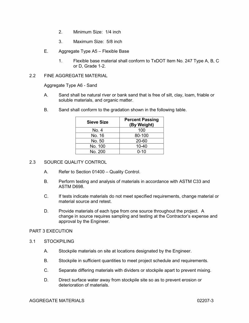
2. Minimum Size: 1/4 inch
3. Maximum Size: 5/8 inch
E. Aggregate Type A5 – Flexible Base
1. Flexible base material shall conform to TxDOT Item No. 247 Type A, B, C or D, Grade 1-2.
2.2 FINE AGGREGATE MATERIAL
Aggregate Type A6 - Sand
A. Sand shall be natural river or bank sand that is free of silt, clay, loam, friable or soluble materials, and organic matter.
B. Sand shall conform to the gradation shown in the following table.
Sieve Size Percent Passing (By Weight)
No. 4 100 No. 16 80-100 No. 50 20-60 No. 100 10-40 No. 200 0-10
2.3 SOURCE QUALITY CONTROL
A. Refer to Section 01400 – Quality Control.
B. Perform testing and analysis of materials in accordance with ASTM C33 and ASTM D698.
C. If tests indicate materials do not meet specified requirements, change material or material source and retest.
D. Provide materials of each type from one source throughout the project. A change in source requires sampling and testing at the Contractor’s expense and approval by the Engineer.
PART 3 EXECUTION
3.1 STOCKPILING
A. Stockpile materials on site at locations designated by the Engineer.
B. Stockpile in sufficient quantities to meet project schedule and requirements.
C. Separate differing materials with dividers or stockpile apart to prevent mixing.
D. Direct surface water away from stockpile site so as to prevent erosion or deterioration of materials.
AGGREGATE MATERIALS 02207-4
3.2 STOCKPILE CLEANUP
A. Remove the stockpile. Leave the area in a clean and neat condition. Grade the site to prevent freestanding surface water.
B. If a borrow area is indicated, leave the area in a clean and neat condition. Grade the site to prevent freestanding surface water.
END OF SECTION
TRENCH AND EXCAVATION SAFETY SYSTEM 02220-1
SECTION 02220
TRENCH AND EXCAVATION SAFETY SYSTEM
PART 1 GENERAL
1.1 SECTION INCLUDES
A. Requirements for a trench and excavation safety system(s) to be designed and furnished by the Contractor for the safety and health of personnel.
1.2 REFERENCES
A. 29CFR1926 - Occupational Safety and Health Standards - Excavations, United States Department of Labor, latest edition.
B. Others - Other applicable federal, state, and local rules for trench construction or excavations.
1.3 REQUIREMENTS
A. The Contractor shall develop, design, and implement a trench and excavation safety system. The Contractor shall bear the sole responsibility for the adequacy of the system.
B. The requirements of 29CFR1926 shall be the minimum requirements for this specification and are adopted as a part of this specification. Other regulations relating to trench and excavation safety shall also be considered a part of this specification as if referenced directly.
C. Should the system require wider trenches than shown, the Contractor shall be responsible for the costs associated with determining adequacy of pipe bedding and class, as well as purchase and installation of alternate and/or additional materials.
PART 2 PRODUCTS
[Not Used]
PART 3 EXECUTION
3.1 Implement the system in accordance with the written system plan and conduct affected work in accordance with the same.
3.2 The system shall be in use during all phases of construction.
3.3 Neither the Engineer nor the Owner will be responsible for ensuring the trench safety system is constructed and utilized in accordance with the safety plan. This shall be the sole responsibility of the Contractor.
END OF SECTION
EXCAVATION, BACKFILL, AND COMPACTION FOR UTILITIES 02225-1
SECTION 02225
EXCAVATION, BACKFILL, AND COMPACTION FOR UTILITIES
PART 1 GENERAL
1.1 SECTION INCLUDES
A. Excavation, backfill, and compaction for water distribution mains, sanitary sewers, manholes, storm drains, junction boxes, inlets and other utility lines and appurtenances and the disposal of excess excavated material.
1.2 RELATED SECTIONS
A. Section 01041 – Job Management.
B. Section 01400 – Quality Control.
C. Section 02205 – Soil Materials.
D. Section 02207 – Aggregate Materials.
E. Section 02732 – Sanitary Sewer Pipe.
1.3 REFERENCES
A. ASTM C33 – Standard Specifications for Concrete Aggregates.
B. ASTM C136 – Standard Test Method for Sieve Analysis of Fine and Coarse Aggregates.
C. ASTM D698 – Test Method for Laboratory Compaction Characteristics of Soil Using Standard Effort.
D. ASTM D2487 – Standard Classification of Soils for Engineering Purposes.
E. ASTM D2922 – Standard Test Methods for Density of Soil and Soil-Aggregate in Place by Nuclear Methods (Shallow Depth).
F. ASTM D3017 – Standard Test Methods for Water content of Soil and rock in Place by Nuclear Methods (Shallow Depth).
G. ASTM D4253 –Vibratory Table Standard.
H. ASTM D4254 – Standard Test Methods for Minimum Index Density and Unit Weight of Soils and Calculations of Relative Density.
I. ASTM D4318 – Standard Test Methods for Liquid Limit, Plastic Limit and Plasticity Index of Soils.
J. OSHA – Occupational Safety and Health Administration and Related Regulations.
EXCAVATION, BACKFILL, AND COMPACTION FOR UTILITIES 02225-2
K. Any other testing required by these specifications and not specifically referenced to a standard shall be performed under ASTM or other appropriate standards as designated by the Engineer.
L. Reference herein or on the drawings to soil classifications shall be understood to be according to ASTM D2487, "Standard Classification of Soils for Engineering Purposes" unless indicated otherwise.
1.4 QUALITY CONTROL
A. The Owner will arrange and pay for density and moisture testing. The testing frequency and methods shall be as requested by the Engineer. The Engineer may waive testing requirements on cohesionless bedding where testing is not practical because of limited space between the pipe and trench walls, however, the minimum number of passes of the compaction equipment shall be achieved.
B. Contractor shall pay for re-testing until acceptable test results are obtained.
1.5 DELIVERY, STORAGE AND HANDLING
Excavated materials to be used for backfill may be deposited in stockpiles at points convenient for rehandling the material during the backfilling process. The location of stockpiles shall be within the limits of construction easements or public right-of-way. The location of stockpiles is subject to the approval of the Owner or the Owner’s representative. Keep drainage channels clear of stockpiled materials.
1.6 PROJECT CONDITIONS
A. Protection
1. Erect sheeting, shoring and bracing as necessary for protection of persons, improvements, existing structures, and excavations.
2. Provide dewatering and drainage necessary to keep excavations free of water.
a. The dewatering system shall maintain the water level a minimum of three feet below the excavation.
b. The Contractor shall provide and maintain all dewatering equipment during excavation, construction, backfill, and until utility is placed in service.
c. The Contractor shall operate the dewatering system continuously without interruption during weekends and/or holidays.
B. Classification
1. Excavations shall include material of whatever nature encountered, including but not limited to clays, sands, gravels, conglomeritic boulders, shales, rock, debris, and abandoned existing structures. Excavation and trenching shall include the removal and subsequent handling of materials excavated or otherwise handled in the performance of the work.
EXCAVATION, BACKFILL, AND COMPACTION FOR UTILITIES 02225-3
2. Bidders must satisfy themselves as to the actual existing subsurface conditions prior to the submittal of a proposal to complete the proposed work.
3. Trench excavation shall consist of excavation to the lines and grades indicated, required for installation of the pipe, pipe bedding, backfill, and to accommodate trench safety systems.
1.7 COORDINATION
A. Verify work associated with lower elevation utilities is complete before placing higher elevation utilities.
PART 2 PRODUCTS
2.1 SOIL MATERIALS
Soil Materials shall be as specified in Section 02205 – Soil Materials.
2.2 CONCRETE
Unless other strength requirements are designated, concrete shall be 2000 psi as specified in Section 03305 – Concrete.
PART 3 EXECUTION
3.1 PROTECTION OR REMOVAL OF UTILITY LINES
A. Notify all utility companies to have their utilities located and marked in the field.
B. The Contractor shall anticipate all underground obstructions such as, but not limited to, water mains, gas lines, storm drains, sanitary sewers, telephone lines, power ducts, concrete, and debris.
1. Any such lines or obstructions indicated on the plans show only the approximate locations and shall be verified in the field by the Contractor.
2. The Owner and Engineer will endeavor to familiarize the Contractor with all known utilities and obstructions but this shall not relieve the Contractor from full responsibility in anticipating all underground obstructions whether or not shown on the plans.
3. Known utility lines in the vicinity of the proposed construction area are shown on the Construction Drawings. At least 72 hours prior to construction in all areas, however, contact Texas One Call to confirm locations of existing utilities.
C. The Contractor shall notify the Engineer of conflicts in grade or horizontal location between the proposed improvements and existing utilities.
D. The Contractor shall, at his own expense, maintain in proper working order and without interruption of service all existing utilities and services which may be encountered in the work.
EXCAVATION, BACKFILL, AND COMPACTION FOR UTILITIES 02225-4
1. With the consent of the Engineer and utility owner, such service connections may be temporarily interrupted to permit the Contractor to remove designated lines or to make temporary changes in the locations of services.
2. The cost of making any temporary changes shall be at the Contractor's expense.
E. The Contractor will be held responsible for any damage to existing structures, work, materials, or equipment because of his operations and shall repair or replace any such damaged structures, work, materials, or equipment to the satisfaction of the Owner at no additional cost to the Owner.
F. The Contractor shall be responsible for protecting existing utilities and for repairs to such facilities in case of damage to same. Should there be relocations or adjustments of utilities necessary to accommodate construction activities, the Contractor shall cooperate with the company or companies involved and will coordinate such relocations with the schedule of work herein. Include the cost of demolition and replacement or adjustment in the bid amount.
G. The spacing for utility lines shall meet the installation requirements and the requirements of the TCEQ as listed in 30 TAC 290.44(e) and 30 TAC 317.13.
3.2 EXAMINATION AND PREPARATION
A. Examine utility routes and coordinate excavation work to eliminate installation conflicts.
B. Allow room for stockpiling excavated material and utility construction material during utility construction.
C. Identify required lines, levels, contours, and datum locations.
D. Protect plant life, lawns, and other features remaining as a portion of final landscaping.
E. Protect benchmarks, existing structures, fences, sidewalks, paving, and curbs from equipment and vehicular traffic.
F. Maintain and protect above and below grade utilities that are to remain.
G. Cut out soft areas of subgrade not capable of compaction in place. Backfill with Aggregate Type A5 – Flexible Base and compact to a density equal to or greater than the requirements for subsequent backfill.
3.3 TRENCH EXCAVATION
A. Procedure
1. Excavate to indicated or specified depths.
2. Excavate by open cut method. Blasting will not be allowed under any circumstances.
EXCAVATION, BACKFILL, AND COMPACTION FOR UTILITIES 02225-5
3. Excavate the trench to an even grade to permit the installation of the pipe so that the full length of the pipe barrel is supported on the proper depth of bedding material. The entire foundation subgrade area in the bottom of the excavations shall be firm, stable material, and the material shall not be disturbed below required grade except as described in this specification. Where the character of the subgrade material is such that proper subgrade cannot be obtained at the elevation indicated, deepen the excavation to a satisfactory subgrade material. Remove the material until a firm, stable, and uniform bearing is reached. The subgrade shall be brought back to the required grade with Aggregate Type A5 – Flexible Base and compacted to a density equal to or greater than the requirements for subsequent backfill.
4. During excavation, stockpile material suitable for backfilling in an orderly manner far enough from the bank of the trench to avoid overloading, slides, or cave-ins. Dispose of unacceptable backfill material and provide suitable material for backfill without additional expense.
5. Grade as necessary to prevent surface water from flowing into trenches or other excavations.
6. Cut banks of trench as nearly vertical as practical except as necessary for trench safety.
7. Remove stones as necessary to avoid point-bearing.
8. Over-excavate wet or unstable soil from the trench bottom to permit construction of a more stable foundation for pipe.
9. Over-excavation shall be filled with Aggregate Type A5 – Flexible Base to the required grade. Compact flexible base to a density equal to or greater than the requirements for subsequent backfill.
10. Excavate the trench to the proper width as shown and specified.
11. Accurately grade the trench bottom to provide proper bedding as required for pipe installation.
12. If any excavation is carried beyond the lines and grades required or authorized, the Contractor shall, at his own expense, fill such space with concrete or other suitable material as directed by the Engineer. No additional payment will be made.
13. Do not interfere with 45 degree bearing splay of foundations.
B. Sheeting and Bracing
Install sheeting and bracing necessary to support the sides of trenches and other excavations as required by current OSHA regulations.
EXCAVATION, BACKFILL, AND COMPACTION FOR UTILITIES 02225-6
C. Water In Excavation
1. Keep work free from ground or surface water at all times.
2. Provide pumps of adequate capacity or other Engineer approved method to remove water from the excavation in such a manner that it will not interfere with the progress of the work or the proper placing of other work.
D. Trenching Progress
1. Trenching operations shall not be in excess of 100 feet ahead of pipe laying operations in urban areas or 1,000 feet in rural areas.
2. No more than two consecutive cross-streets may be closed to traffic at any given time. Any street closings must be approved by the Owner and those having authority over the streets to be closed.
E. Existing Lawns and Shrubbery
1. The Contractor shall take particular care to preserve existing lawns and shrubbery.
2. Make minor pipe alignment changes as may be necessary with approval from the Engineer.
F. Existing Pavement
1. Existing pavement over trenches shall be removed to a width of one foot outside of the trench on each side.
2. Remove existing pavement to a neat line by sawing.
3. Remove brick pavement by hand, deliver, and stack as directed by the Owner.
G. Protection of Existing Structures and Utilities
1. Prior to the start of construction, communicate with the local representatives of utility companies, including but not limited to oil, gas, telephone, and communications companies, as well as local water and sewer utilities operating in the proposed construction area. Seek the utility companies’ assistance in locating existing facilities to avoid conflicts during construction. The location, number, depth, and owner of utilities indicated are for information purposes only. All utilities and structures may not be shown or may not be in the location shown.
2. Where construction endangers adjacent structures, utilities, embankments, and/or roadways, the Contractor shall, at his own expense, carefully support and protect such structures so that no damage occurs throughout the construction process. If damage should occur, the Contractor shall be responsible for restoring the damaged structure to a condition acceptable to the owner of that structure and shall bear all cost of repair and/or replacement.
EXCAVATION, BACKFILL, AND COMPACTION FOR UTILITIES 02225-7
3. Repair or replace damaged street surfaces, driveways, sidewalks, curbs, gutters, fences, drainage structures, or other such facilities to the satisfaction of the Owner. Structures shall be returned to a condition equal to or better than the original condition and of same or better material and quality.
3.4 PIPE BEDDING
A. Pipe Zone
The pipe zone is defined as including the pipe bedding, up to one-half the pipe diameter (the springline), and the initial backfill to 12 inches above the top of the pipe.
B. Class A Bedding
1. Where shown, the Contractor shall install the pipe in concrete encasement.
2. Concrete for encasement shall be 2000 psi compressive strength.
3. Precautions shall be used to prevent pipe movement or deflection during concrete placement.
C. Class B Bedding
1. Excavate the bottom of the trench to four inches below the bottom of the pipe and a minimum of four inches on either side of the pipe.
2. Place a minimum of four inches of compacted Aggregate Type A3 – Type 2 Pipe Embedment up to the flow line of the pipe before the pipe is laid.
3. Install pipe, place additional Aggregate Type A3 – Type 2 Pipe Embedment to spring line, and compact.
4. Continue with compacted Aggregate Type A3 – Type 2 Pipe Embedment to 12 inches above the top of the pipe.
D. Class C Bedding
1. Excavate the trench to four inches below the bottom of the pipe and a minimum of four inches on either side of the pipe.
2. Place a minimum of four inches of compacted Aggregate Type A6 – Sand up to the flow line of the pipe before the pipe is laid.
3. Install pipe, place additional Aggregate Type A6 – Sand up to the spring line, and compact.
4. Continue with compacted Aggregate Type A6 – Sand to 12 inches above the top of the pipe.
EXCAVATION, BACKFILL, AND COMPACTION FOR UTILITIES 02225-8
E. Class D Bedding
1. Excavate the trench to four inches below the bottom of the pipe and a minimum of four inches on either side of the pipe.
2. Place a minimum of four inches of compacted stockpiled sand up to the flow line of the pipe before the pipe is laid.
3. Install pipe, place additional stockpiled sand backfill up to the spring line, and compact.
4. Continue with compacted stockpiled sand to 12 inches above the top of the pipe.
F. Bedding Notes
1. Each pipe section shall have a uniform bearing on the embedment for the full length of the pipe except immediately at the joint.
2. Adjustment to grade line shall be made by scraping away or filling with embedment materials. Wedging or blocking up of pipe will not be permitted.
3. After each pipe has been graded, aligned, placed in final position on the bedding material, and the joint made, sufficient embedment material shall be deposited and compacted under and around each side of the pipe and back of the bell or end thereof to hold the pipe in proper position and alignment during subsequent pipe jointing and embedment operations.
4. Embedment material shall be deposited simultaneously on each side of pipe and compacted uniformly to the spring line.
5. Bedding shall be placed in maximum eight-inch loose lifts.
6. Sheeting and shoring will not be allowed in the pipe zone during or after installation of the pipe or embedment material, unless special provisions are made to ensure the specified compaction of bedding and pipe alignment is maintained after removal of sheeting and shoring.
7. Compact the bedding and backfill to a minimum of 95 percent of standard proctor maximum dry density per ASTM D698 maintaining moisture within two percentage points of optimum.
8. Compact cohesionless fill on which it is not practical to control the density by proctor methods to a minimum of 75% of relative density as determined by ASTM D4253 and D4254, or at the discretion of the Engineer, by a field compaction mold method correlated to ASTM D4253 and D4254. Compact cohesionless fill at a moisture content within a range that accommodates consistent placement and compaction to the minimum relative density specified above.
EXCAVATION, BACKFILL, AND COMPACTION FOR UTILITIES 02225-9
9. Place no embedment material during freezing weather or upon frozen subgrades or previously placed frozen embedment materials.
3.5 BACKFILLING
A. Backfill trenches to the ground surface with material as specified. Mound excess material over the trench as shown.
B. Reopen trenches improperly backfilled to the depth required for proper compaction.
C. Refill and compact as specified or otherwise correct the condition in a manner approved by the Engineer.
D. Place no backfill material during freezing weather or upon frozen subgrades or previously placed frozen embedment or backfill materials.
E. Above the pipe zone, backfill with Soil Type S2 – Type 1 Common Fill in eight-inch loose lifts. Compact each lift to a minimum of 95% standard proctor density within two percentage points of optimum moisture.
F. All forms, lumber, trash, and debris shall be removed from all trenches.
G. Backfill for manholes, utility pull boxes, and other utility structures shall be placed in accordance with applicable specification sections.
H. For backfill under pavement or foundations, the Contractor shall place compacted Soil Type S3 – Type 2 Common Fill above the pipe zone in eight-inch loose lifts. Compact to 95% of maximum density within two percentage points of optimum moisture per ASTM D698.
I. In areas that had topsoil prior to construction, a minimum of six inches of Soil Type S5 – Topsoil shall be placed as the final layer of backfill.
3.6 DISPOSAL OF EXCESS MATERIAL
A. Remove waste and excess excavated material from the construction site before final inspection.
B. Legally dispose of material at a licensed site or with written and notarized permission from the property owner for a private disposal site.
C. All cost associated with waste material removal and disposal shall be paid for by the Contractor.
END OF SECTION
CLEARING AND GRUBBING 02230-1
SECTION 02230
CLEARING AND GRUBBING PART 1 GENERAL
1.1 SECTION INCLUDES
Labor, materials, equipment, and incidentals necessary to perform operations in connection with clearing, grubbing, and disposal of cleared and grubbed materials.
1.2 DEFINITIONS
A. CLEARING: Clearing is defined as the removal of trees, shrubs, bushes, and other organic matter at or above original ground level.
B. GRUBBING: Grubbing is defined as the removal of stumps, roots, boards, logs, and other organic matter found at or below original ground level.
PART 2 PRODUCTS
[Not Used]
PART 3 EXECUTION
3.1 PREPARATION
A. Mark areas to be cleared and grubbed prior to commencing clearing operations. Engineer shall approve clearing and grubbing limits prior to commencement of clearing operations.
B. Trees and shrubs outside of the clearing limits, which are within 10' of the clearing limits, shall be clearly marked to avoid damage during clearing and grubbing operations.
C. With the Engineer’s approval, the Contractor may remove trees and brush outside the clearing limits, but within the immediate vicinity of the work, when the trees or brush interfere with or retard the progress of construction operations.
D. Clearly mark trees and shrubs within the clearing limits which are to remain and protect the trees and shrubs from damage during the clearing and grubbing operations.
E. The clearing limits shall not extend beyond the project limits.
F. Establish the clearing limits as follows:
1. Force Main plus minimum additional width needed for installation equipment and excavated material stockpile.
2. Force main plus additional 5’ east along Park Road 5.
3. Concrete structures plus 10' beyond the edge of the footing.
CLEARING AND GRUBBING 02230-2
G. Establish the grubbing limits as follows:
1. Follow limits described for clearing
3.2 INSTALLATION
A. CLEARING
B. Clearing shall consist of the felling and the satisfactory disposal of trees and other vegetation together with the down timber, snags, brush, rubbish, and debris occurring within the area to be cleared.
C. GRUBBING
1. Grubbing shall consist of the removal and disposal of stumps and roots larger than 1" in diameter.
2. Extend grubbing to the depth indicated below. In the case of multiple construction items, the greater depth shall apply.
a. Precast Concrete Structures and Fiberglass Basins – 12” below the bottom of the structure
3.3 FIELD QUALITY CONTROL
A. Completely remove timber, logs, roots, brush, rotten wood, and other refuse from the Owner's property.
B. Disposal of materials in streams shall not be permitted and no materials shall be piled in stream channels or in areas where it might be washed away by floods.
C. Timber within the area to be cleared shall become the property of the Contractor and the Contractor may cut, trim, hew, saw, or otherwise dress felled timber within the limits of the Owner's property provided the timber and waste material is disposed of in a satisfactory manner.
D. Materials shall be removed from the site weekly, unless permission is granted by the Engineer to store the materials for longer periods. Under no circumstances will the Contractor be allowed to bury timber and/or waste material on-site.
END OF SECTION
PAVEMENT REPLACEMENT 02511-1
SECTION 02511
PAVEMENT REPLACEMENT
PART 1 GENERAL
1.1 SECTION INCLUDES
The repair and replacement of existing pavement including, but not limited to, asphalt (hot-mix, surface treatment, etc.), brick, concrete, gravel, oil-sand, and unimproved streets and roadways.
1.2 RELATED SECTIONS
A. Section 02225 – Excavation, Backfill, and Compaction for Utilities.
1.3 REFERENCES
A. Texas Department of Transportation – Standard Specifications for Construction of Highways, Streets, and Bridges.
1. TxDOT Item 247 – Flexible Base Material.
2. TxDOT Item 300 – Asphalts, Oils, and Emulsions.
3. TxDOT Item 310 – Prime Coat (cutback asphaltic material only).
4. TxDOT Item 340 – Hot Mix Asphaltic Concrete Pavement.
B. ACI 301 – Specifications for Structural Concrete.
C. ASTM A615 – Deformed and Plain Billet Steel Bars.
D. ASTM A616 – Rail Steel Deformed and Plain Bars.
E. ASTM C150 – Standard Specification for Portland Cement.
F. ASTM C260 – Air-Entraining Admixtures for Concrete.
G. ASTM C494 – Chemical Admixtures for Concrete.
1.4 SUBMITTALS
A. The Contractor shall submit mix designs for asphalt/concrete, including additive modifiers, for review and approval at least 30 days before any pavement is placed.
1.5 DELIVERY, STORAGE AND HANDLING
A. Asphaltic concrete material shall be hauled in tight trucks previously cleaned of all dirt and foreign material.
PAVEMENT REPLACEMENT 02511-2
B. All material shall be delivered and immediately placed or stockpiled. Care shall be taken when stockpiling to prevent contamination of materials.
1.6 ENVIRONMENTAL REQUIREMENTS
A. Asphaltic concrete shall not be placed when the ambient temperature is below 60° F and is falling.
B. Asphaltic concrete may be mixed and placed when the ambient temperature is above 50° F and is rising.
C. Portland cement concrete shall not be placed when the ambient temperature is below 40°and falling.
D. Portland cement concrete may be placed when the ambient temperature is above 35° and rising.
E. Paving materials shall not be placed on wet or frozen subgrade.
PART 2 PRODUCTS
2.1 FLEXIBLE BASE
Aggregate Type A5 – Flexible Base.
2.2 PRIME COAT
A. Asphaltic materials shall be in accordance with TxDOT Item 300.
B. Provide grade MC-30, or as approved by the Engineer, in accordance with TxDOT Item 310.
2.3 TACK COAT
A. Asphaltic materials shall be in accordance with TxDOT Item 300.
B. Provide grade RC-250 or as approved by the Engineer.
2.4 HOT MIX ASPHALTIC CONCRETE SURFACE COURSE
TxDOT Item 340, Type D.
PART 3 EXECUTION
3.1 EXTENT OF REPAIR
A. Pavement shall be restored to its original condition or better.
B. The Contractor shall repair all pavement cuts unless otherwise noted on the plans.
PAVEMENT REPLACEMENT 02511-3
C. Existing pavement shall be removed and replaced to a minimum of the trench top width plus one foot on each side. The cost of sawcutting and removal of existing pavements shall be considered subsidiary to the unit price for pavement repair.
3.2 FIELD QUALITY CONTROL
A. The trench backfill supporting the pavement replacement shall be installed in accordance with Section 02225 – Excavation, Backfill, and Compaction for Utilities.
B. If, in the judgment of the Engineer, the quality of materials used or the completed installation (including compacted density or thickness) is questionable, the Engineer may conduct the appropriate tests to verify the quality of the installation.
1. If the pavement fails, these tests will be at the expense of the Contractor. If the pavement passes, the tests will be paid for by the Owner.
2. If the installation does not meet the criteria listed in this section, the material shall be removed and replaced at the expense of the Contractor so that the installation meets the criteria in this section.
3.3 TRAFFIC CONTROL
A. The Contractor shall maintain lights and/or barricades around the work areas as necessary until the pavement is ready for traffic.
B. Control work so as to minimize disruption of normal traffic flow and prevention of access to normal traffic routes.
3.4 GRAVEL, OIL-SAND, AND OTHER NON-PERMANENT PAVEMENTS
A. Ensure trench is backfilled in accordance with section 02225 – Excavation, Backfill, and Compaction for Utilities.
B. Place and compact a layer of Aggregate Type A5 – Flexible Base over the ditch to a compacted depth of 8 inches for the finished surface of the roadway.
C. The thickness of each layer before compaction shall not exceed six inches.
3.5 ASPHALT DRIVES
A. Ensure the trench is backfilled in accordance with section 02225 – Excavation, Backfill, and Compaction for Utilities.
B. Flexible Base Course
1. Place and compact Aggregate Type A5 – Flexible base in accordance with TxDOT Item 247 over the trench within the limits of the existing asphalt pavement. The thickness shall be as shown on the plans.
2. The base course shall be placed, mixed, and compacted in one lift.
PAVEMENT REPLACEMENT 02511-4
C. A prime coat shall be applied at a rate of 0.20 to 0.40 gallons per square yard over compacted flexible base and shall be cured for a minimum of 24 hours.
D. A tack coat shall be applied to saw-cut edges, adjacent concrete, or other appurtenances within the confines of the paved area. Apply at a rate of 0.05 to 0.15 gallons per square yard.
E. Installation of a minimum thickness of two inches of asphalt pavement shall meet the requirements of TxDOT Item 340 or as approved by the Engineer.
F. Compaction
1. The Contractor shall use any equipment deemed necessary.
2. All equipment shall be approved by the Engineer.
3. The density shall be as specified in TxDOT Item 340.
G. Surface Tests
1. The finished surface of the replacement asphalt shall be at the same elevation and grade as the original pavement before cutting or as shown on the plans.
2. The completed surface, when tested with a straightedge spanning between the undisturbed saw-cut pavement sections shall show no deviation in excess of 1/8 inch.
H. Construction Joints
1. Place courses as nearly continuously as possible.
a. If work is interrupted, cut back the previously-laid material to produce a slightly beveled edge for the full thickness of the course.
b. Remove material which has been cut away and lay the new mix against the fresh cut.
2. When the asphalt is laid against existing asphalt, the existing asphalt
shall be cut to provide a straight smooth joint.
END OF SECTION
MANHOLES 02607-1
SECTION 02607
MANHOLES PART 1 GENERAL
1.1 SECTION INCLUDES
Modular precast concrete manhole sections with tongue-and-groove joints, covers, anchorage, and accessories.
1.2 RELATED SECTIONS
A. Section 01400 – Quality Control.
B. Section 02207 – Aggregate Materials.
C. Section 03305 – Concrete.
1.3 REFERENCES
A. ASTM A48 – Gray Iron Castings.
B. ASTM C478 – Precast Reinforced Concrete Manhole Sections.
C. ASTM C923 – Resilient Connectors Between Reinforced Concrete Manhole Structures and Pipes.
1.4 SUBMITTALS
Provide manufacturer’s data on manhole rings and covers, and manhole cones, risers, and bases. Include dimensions, configurations, materials, and any other data necessary to show that the items meet this specification.
1.5 QUALIFICATIONS
Manufacturers shall be companies specializing in manufacturing products specified in this section with a minimum of three years of documented experience.
PART 2 PRODUCTS
2.1 MATERIALS
Manhole sections shall be reinforced precast concrete in accordance with ASTM C478.
2.2 COMPONENTS
A. Rings and Covers
1. Cast iron in accordance with ASTM A48, Class 30B.
2. Machined flat bearing surface.
MANHOLES 02607-2
3. Removable cover designed for H-20 loading.
4. Molded with “SANITARY SEWER”.
5. Ring and cover shall weigh a minimum of 295 pounds.
6. Pre-approved Manufacturers
a. Tyler Utilities.
b. Neenah.
c. Bass & Hays.
d. East Jordan Iron Works.
B. Seals shall be O-ring rubber gaskets.
C. Resilient connectors shall be A-Lok or Engineer approved equal.
2.3 CONFIGURATION
A. Shaft Construction
1. Concentric with flat top section.
2. Sleeves to receive pipe sections.
3. Joints sealed with profile rubber gaskets.
B. Shape shall be cylindrical.
C. Standard manhole sections shall have a minimum inside diameter of 48 inches. For manhole sections other than standard, the minimum inside diameter shall be as indicated on the plans.
D. The depth shall be as indicated.
E. The clear lid opening shall be 30 inches in diameter or as indicated on the plans.
F. Provide openings as indicated or required.
G. Resilient connectors shall be cast into the wall of the manhole for pipe connections.
H. Grout manhole inverts after pipes are in place. Bench sides as required. Slope for drainage. Inverts shall meet the requirements of 30 TAC 317.2 (c)(5)(E).
PART 3 EXECUTION
3.1 EXAMINATION
A. Verify that the items provided for in other specification sections are properly sized and located.
MANHOLES 02607-3
B. Verify that the excavation for manholes is correct.
C. Coordinate placement of inlet and outlet pipe or duct sleeves required by other sections.
3.2 PLACING MANHOLE SECTIONS
A. Adjust the elevation of the foundation material as required to attain proper grade and alignment of the base section.
B. Place manhole sections plumb and level, adjust to correct elevations, block and pour the base section.
C. Sleeves in the bottom sections shall be appropriate for the pipe being laid and shall have identifying markings to facilitate their being used in the correct locations.
D. The connecting pipe for installation with resilient connectors shall be plain end, square cut spigots that shall not protrude more than one inch inside the manhole.
E. Grout the invert to achieve slope to the exit piping. Trowel smooth. Contour as required.
F. Manhole height shall be adjusted by using precast grade rings set between the ring and cover and the cone. No more than two grade rings may be used without Engineer approval.
G. Set the ring and cover level and to correct elevations.
H. Coordinate with other specification sections and the plans to provide correct size, shape, and location.
3.3 TESTING
A. Manholes shall be tested for leakage separately and independently of the wastewater lines according to section 01400 – Quality Control.
B. The maximum leakage for hydrostatic testing shall be 0.025 gallons per foot of diameter per foot of manhole depth per hour. Alternate test methods must ensure compliance with the above allowable leakage.
C. If a manhole fails a leakage test, the manhole must be made watertight and retested at the Contractor’s expense.
D. Testing must meet the requirements of 30 TAC 217.
END OF SECTION
SANITARY SEWER PIPE 02732-1
SECTION 02732
SANITARY SEWER PIPE
PART 1 GENERAL
1.1 SECTION INCLUDES
Furnish labor, materials, equipment, and incidentals necessary to install gravity flow sanitary sewer lines.
1.2 RELATED SECTIONS
A. Section 01400 – Quality Control.
B. Section 02225 – Excavation, Backfill, and Compaction for Utilities.
1.3 REFERENCES
A. ANSI/AWWA C105.
B. ANSI/AWWA C115.
C. ANSI/AWWA C150.
D. ANSI/AWWA C151.
E. ASTM D1248.
F. ASTM D1785
G. ASTM D3034.
H. ASTM D3212.
I. ASTM D3350.
J. ASTM F477.
K. ASTM F714.
L. AWWA C110.
M. AWWA C111.
1.4 SUBMITTALS
Submittals shall include product data sheets on all piping used in the project.
SANITARY SEWER PIPE 02732-2
1.5 QUALITY ASSURANCE
A. Certification
If requested by the Engineer, the pipe manufacturer shall provide certification that the pipe supplied conforms to these specifications and shall include laboratory test results that support such certification. If the manufacturer is unable to provide the certification, an independent testing facility shall be utilized and retained at no cost to the Owner. The pipe supplied shall be permanently marked with the manufacturer's name, the date of manufacture, and identification with the tests performed to warrant its certification as being in conformance with this standard.
B. Experience Requirements
Pipe shall be the product of a manufacturer who has had a minimum of 10 years successful experience manufacturing pipe of the particular type specified and the total pipeline shall be a product of one pipe manufacturer. The manufacturer shall have a minimum of 10 years successful experience in the design and manufacturing of pipe joints of similar design, working pressure, pipe diameter, and wall thickness as specified.
C. Owner Testing and Inspection
Pipe may be subject to inspection by an independent testing laboratory that will be selected and retained by the Owner. Representatives of the laboratory or the Engineer shall have access to the work whenever it is in preparation or progress, and the pipe manufacturer shall provide proper facilities for access and for inspection. Material and pipe which are discovered to be defective or which do not conform to the requirements of this specification shall be subject to rejection at any time prior to final acceptance of the pipe.
D. Inspection
An inspection of the pipe after delivery to the project shall be made by a representative of the Owner. Pipe with visible defects which are indicative of poor structural condition or poor workmanship shall be rejected and replaced without cost to the Owner. Visible defects shall include cracks of any type, honeycombs, or any other defects of poor workmanship. Any pipe rejected shall not be returned to the project under any condition.
PART 2 PRODUCTS
2.1 GRAVITY SYSTEMS USING PVC PIPE
A. PVC pipe shall be SDR 26 pipe that meets the requirements of ASTM D3034 for sewer pipe with solvent cement joints.
B. All fittings shall be DWV. 90 degree bends shall be sweeps.
SANITARY SEWER PIPE 02732-3
2.2 PRESSURE FORCE MAIN SYSTEM USING PVC
A. Pipe shall be Schedule 40 PVC that meets the requirements for ASTM D1785 – Polyvinyl Chloride (PVC) Plastic Pipe, Schedule 40.
B. All pipe shall bear the NSF seal of approval
C. For pipe larger than two inches in diameter, the joints shall be integral bell with a flexible elastomeric seal. For pipe smaller two inches in diameter and smaller, joints shall be glued.
2.3 COMBINATION AIR VALVE
A. Combination air valves (CAV) shall provide the function of an air and vacuum valve and an air release valve in a single body.
B. CAV shall have a reinforced nylon body and a two-inch threaded connection.
C. CAV shall be designed for a low pressure range and have a working pressure range of 0.725 to 87 psi.
D. CAV shall be D-025-LP by A.R.I. USA, Inc. or Engineer approved equal.
PART 3 EXECUTION
3.1 INSTALLATION
A. Preparation
1. Do not lay pipe in water or when trench or weather is unsuitable for work. Keep water out of trench until jointing is complete and backfill is placed to the top of the pipe. When work is not in progress, close the ends of the pipe and fittings securely so that no water, earth, or other substances will enter the pipe or fittings.
2. Place pipe so that the full length of each section rests solidly upon pipe bedding with recesses excavated to accommodate joints. Take up and re-lay pipe when grade or joint is disturbed after laying.
3. Cut pipe neatly using approved type mechanical cutter without damaging pipe. Use wheel cutters when possible.
B. Bedding for PVC pipe shall be Class D as specified in Section 02225 – Excavation, Backfill, and Compaction for Utilities unless otherwise specified or shown on the plans.
C. Carefully lower pipe into the trench to avoid damage to the pipe. Remove dirt and trash from the pipe while suspended. Keep pipe clean during laying operations and seal the pipe against the entrance of objects at the close of each operating day.
D. Make push-on joints in accordance with the manufacturer’s recommendations. Lay spigot ends downstream and insert into bell to full depth.
SANITARY SEWER PIPE 02732-4
E. Install pipe to the lines and grades indicated.
F. Contractor shall not lay any pipe in fill areas until fill has been completed and properly compacted to a minimum of two feet above the proposed top of pipe.
G. Sanitary sewer lines shall not be laid within nine feet of water lines. When this separation distance cannot be achieved, the sewer and water lines shall be made to comply with 30 TAC Chapters 217 and 290.
3.2 FIELD QUALITY CONTROL
A. Testing shall be as specified in Section 01400 – Quality Control.
B. Do not enclose or cover any work until inspected.
END OF SECTION
SEWAGE LIFT STATION 11310-1
SECTION 11310
SEWAGE LIFT STATION PART 1 GENERAL
1.1 SECTION INCLUDES
Furnish labor, materials, equipment and incidentals necessary to install a complete and functioning sewage lift station including submersible non-clog wastewater pumps, pump control panel, controls and all associated equipment. Furnish pumps, motors, discharge elbows, guiderail bases, guiderails, lifting chains, cable holders, access covers and any other equipment, accessories and appurtenances necessary for a complete and operable system.
1.2 REFERENCES
A. Section 16100 – Basic Materials and Methods for Electrical Installations.
B. Section 16300 – Power Distribution Devices.
1.3 QUALITY ASSURANCE
MANUFACTURER'S REPRESENTATIVE FOR STARTUP AND TESTING
The services of the Manufacturer's technical representative shall be provided for pre-startup installation checks, startup assistance, training of Owner's operating personnel, troubleshooting and other services as required in Division 16 specifications.
1.4 SUBMITTALS
A. Shop drawings shall include a complete description of the equipment offered including control and mounting system. Shop drawings shall include catalog cuts and pertinent engineering data required to fully evaluate the equipment. Characteristic curves shall be submitted with the shop drawings showing the capacity, head, efficiency, and brake horsepower throughout the full operating range of the pump. Complete specifications on the control equipment including a list of optional features shall be submitted with the shop drawings. Submittal data shall be in such form and so presented that the Engineer may readily review the data.
B. The manufacturer shall submit with the shop drawings a list of 10 similar installations which have been in satisfactory operation for at least one year.
C. Data sheets supplying the following information for the pumping units shall be submitted with the shop drawings.
Pump
1. Make and type of pump
2. Speed (RPM)
SEWAGE LIFT STATION 11310-2
3. Horsepower at rated head (HP)
4. Total weight of pump and motor (Lbs.)
5. Rated capacity and head on pump curve (GPM/Feet TDH)
Motor
6. Make and type of motor
7. Brake horsepower of motor (HP)
8. Locked Rotor Current at full nameplate voltage (Amps)
9. Full load current at full nameplate voltage (Amps)
10. Motor service factor
11. Insulation class and temperature rise at service factor load
Controls
12. Pump Control Panel including panel layout, bill of material (BOM), control schematic, and vendor data sheets of the material listed in the BOM.
13. Level Float
14. Level Transducer and Controller
D. A minimum of four (4) copies of the operation and maintenance manuals for the components of the system shall be provided to the Engineer prior to start-up acceptance by the Engineer.
1.5 PUMPS
A. Submersible solids handling pumps shall meet the performance conditions tabulated as follows when driven at a speed not exceeding 3600 RPM.
B. The following pump model is provided for reference. Pumps shall meet the requirements as scheduled. Pumps shall be Goulds, Myers, Zoeller or Barnes or Engineer approved equal.
1. Goulds Submersible Grinder Pump 1GA71G1LD, 1 1/2” discharge, 3 HP, 230 volts, 1 phase.
Capacity, GPM 31 TDH, feet 80
1.6 WARRANTY
The manufacturer shall guarantee for one year from the date of the Certificate of Acceptance that the pumping design and equipment will be free from defects in
SEWAGE LIFT STATION 11310-3
materials and workmanship. A full written parts and service warranty shall be provided on the complete system for this period of one year.
1.7 CONTROL NARRATIVES
A. The lift station wet well level shall be provided with one float level switch and a level transducer. Each pump shall alternate being the lead or lag pump via a pump alternator relay. The level transducer signal shall be connected to the level indicating controller. The output relay contact set points of the controller shall include low level alarm, pump off, first pump on, second pump on and high level alarm. The float switch shall provide a high level alarm. The float switch shall be wired parallel with the level transducer high level output for redundant alarm.
1.8 INTERLOCKS
A. The lift pumps will shutdown and the alarm red flashing light and audible horn will be activated in the event that one of the associated pump conditions occur:
1. Low level alarm
2. High level alarm
3. Pump motor high moisture detected (Typical for each pump)
4. High motor winding temperature detected (Typical for each pump)
1.9 AUXILLIARY ALARM CONTACTS
A. The lift pump control panel shall have following auxiliary normally open dry contacts rated for 120VAC to be connected to the autodialer system.
1. Low level alarm
2. High level alarm
3. Pump No. 1 motor high moisture detected
4. Pump No. 1 High motor winding temperature detected
5. Pump No. 2 motor high moisture detected
6. Pump No. 2 High motor winding temperature detected
PART 2 PRODUCTS
2.1 SUBMERSIBLE SEWAGE PUMP
A. Each pump, motor and cable assembly shall be furnished in one integral unit, factory assembled by the pump manufacturer.
B. The pump design shall be such that the pumping unit will be automatically and firmly connected to the discharge piping when lowered into place on its mating discharge connection. The discharge connection shall be permanently installed
SEWAGE LIFT STATION 11310-4
in the wet well. The pump shall be easily removable for inspection or service, requiring no bolts, nuts or other fastenings to be disconnected. Connection and disconnection of the pumping unit from the discharge piping shall not require personnel to enter the wet well. Sealing of the pumping unit to the discharge connection shall be accomplished by a machined metal to metal watertight contact. No portion of the pump shall bear directly on the sump floor.
C. Sealing design shall incorporate metal-to-metal contact between machined surfaces. Critical mating surfaces where watertight sealing is required shall be machined and fitted with nitrile rubber O-rings. Fittings will be the result of controlled compression of rubber O-rings in two planes and O-ring contact of four sides without the requirement of a specific torque limit.
D. Major parts, such as the stator casing, oil casing, sliding bracket, volute, impeller and base coupling shall be constructed of cast iron. Surfaces coming into contact with the pumped liquid shall be protected by a factory-applied epoxy coating or shall be stainless steel. External bolts, nuts, and fastening hardware shall be 300 series stainless steel.
E. The rotating cutter shall be of gray cast iron, Class 35B. The cutter ring shall be 316L stainless steel.
F. Pump and motor shaft shall be the same unit. The pump shaft is an extension of the motor shaft. Couplings shall not be acceptable. The pump shaft shall be AISI type 431 stainless steel.
G. The pump assembly shall also be capable of running dry or partially submerged for extended periods without any damage to the pump, motor, seals, or accessories.
H. The cable entry seal design shall preclude specific torque requirements to insure a watertight and submersible seal. The cable entry shall consist of a single cylindrical elastomer grommet, flanked by washers, all having a close tolerance fit against the cable outside diameter and the entry inside diameter and compressed by the body containing a strain relief function, separate form the function of sealing the cable. The assembly shall provide ease of changing the cable when necessary using the same entry seals.
2.2 MOTOR
A. The motor shall be housed in an air-filled, watertight casing and shall have moisture resistant Class F insulation rated for 155º C. The motor shall be NEMA Design B and designed for continuous duty in a submerged environment. The nameplate motor service factor shall be at least 1.15. The motor shaft shall be stainless steel. The power cable shall be sized according to the NEC and ICEA standards and shall be of sufficient length to reach the junction box without the need of any splices.The motor shall be provided with thermal switches embedded in the windings to protect the motor from burnout due to excessive heating. Each motor shall also be provided with a seal failure probe to shut down its motor on seal failure. The motors shall be UL listed and name plated as explosion proof for Class I, Group D, Division 1 areas. The power cables shall be type SO.
SEWAGE LIFT STATION 11310-5
B. The electrical cable entranceway to the motor shall be provided with positive strain relief to prevent leakage or pull-out of the cable in the event that a force is accidentally placed on the cable during the raising or lowering of the pump. One spare set of cable seal accessories shall be provided.
C. The motor, cable and electrical controls shall be sized, furnished, and installed so that the motor shall never exceed the nameplate rating at any point on the pumping curve. Splices and/or junction boxes in the pump basin shall not be acceptable.
2.3 ACCESSORIES
A. Access Covers
Heavy duty aluminum access covers shall be constructed of minimum ¼” plate. Access cover doors shall be provided with hasp and staple for locking. The structural frame for the cover shall be designed to support 150 lbs. per square foot. The supplier shall provide the construction details and dimensions for the cover to the Contractor so that he will have adequate information to construct the adjacent flooring system. Suitable brackets shall be provided to mount the lifting chain, power cable supports and any other accessories that are not mounted on the lower level. All accessories shall be mounted so that they are not disturbed during removal of the pumps for routine maintenance. The access cover parts in contact with concrete or dissimilar metals shall be provided with suitable protection against corrosion.
B. Discharge Elbows and Guiderail Bases
A permanently installed discharge connection elbow shall be provided for each pump which is to be installed in the wet well. This connection shall be secured by stainless steel anchor bolts embedded in the concrete. Raised concrete pads under the pump bases shall be constructed by the Contractor according to manufacturer’s recommendations. Lower guiderail holders shall be integral with the pump discharge elbow.
C. Guiderails and Lifting Chains
The guiderails and lifting cables shall be sized by the pump supplier. Guiderails shall be constructed of stainless steel as shown on the Plans. Lifting chain and shackles shall be stainless steel (3/16” min). Intermediate and upper guiderail brackets shall be provided by the pump supplier to achieve the arrangement shown on the plans. Lifting cables shall include all necessary fittings and hooks as required for lifting and securing cable at access hatch. Guide bars shall be of no less than standard weight stainless steel pipe of the size indicated on the plans. The guide bars shall be installed for the purpose of pump installation and removal only and shall not support any portion of the pump.
D. Submersible Level Transducer
Primary level control shall be provided by a submersible level transducer. Transducer material of construction shall be titanium. Moisture protection shall be provided via a vent filter. The assembly shall include lightning protection. The
SEWAGE LIFT STATION 11310-6
minimum range shall be 20 feet of water. Output shall be a 4-20 mA signal. Transducer and controller shall be Esterline model 735. No substitutions will be accepted.
E. Float Switch
Backup control shall be provided by a single float switch for high level alarm. Switch shall consist of a switch sealed in a corrosion resistant polypropylene housing with a minimum of 18 gauge, 2-wire, SJOW/A jacketed cable. Mercury switches shall not be accepted. The cable shall be of sufficient length to reach the junction box with no splices. The level controls shall be suspended from a stainless steel bracket so that adjustment or replacement may be done without the use of any tools. Level controls shall be UL/CSA listed. Level switches shall be wired to provide intrinsically safe control wiring in the wet well (a Class I, Group D, Division 1 area).
F. ELECTRICAL CONTROL PANEL
1. Scope of Work
a. Furnish, install, and test an electrical control panel as specified herein. Control panel shall consist of all equipment necessary for a fully operational system.
2. Quality Assurance
a. The control panel manufacturer shall demonstrate at least three years of continuous field operating experience in control panel design and fabrication. Submit customer/user list with telephone numbers, addresses and names of customer/user representatives.
b. The factory authorized service and parts organization shall be able to respond to any service call for the project within eight hours. Provide the name and address of the factory-authorized service and parts organization nearest to the project location at the time of the bid.
c. Equipment components and devices shall be UL labeled to the extent possible where ever UL standards exist for such equipment.
d. The complete control panel assembly shall be UL certified or carry a UL listing for "Industrial Control Panels".
e. The control panel shall meet all applicable requirements of the National Electrical Code.
3. Rating
a. The control panel shall operate on a power supply of 240 Volt, single phase.
SEWAGE LIFT STATION 11310-7
b. The overall withstand and interrupting rating of the equipment and devices shall not be less than 10,000 amperes symmetrical at 240 Volts or less. All circuit breakers and combination motor starters shall be fully rated for the above fault current interrupting capacity. Series connected short circuit ratings will not be acceptable.
4. Components
a. Main circuit breaker shall be NEMA rated and shall have an operating handle mechanically interlocked with the enclosure to allow the panel door to open only if the switch is in open position. Size of circuit breaker size is as shown on the control wiring diagrams on the drawings. Otherwise, circuit breaker shall be adequately sized for the control panel loads.
b. Combination starters Units
1) Combination starters shall include a motor circuit protector (MCP) in series with a motor controller (as specified below) and an overload protective device. The MCP shall have an adjustable magnetic trip range and a trip test feature. MCP's shall be labeled in accordance with UL489.
c. Electromechanical Motor Starters
1) Motor starters: electrically operated, number of Pole, Voltage rating, starter types, and NEMA size are as shown on the drawings. IEC rated starters shall have continuous current ratings equal to or greater than the continuous current ratings listed in NEMA ICS 2.
2) Starters shall have 120 Volt encapsulated operating coils, an individual control power transformer with primary and secondary fuses, and silver cadmium oxide renewable line contacts.
3) Auxiliary contacts: accommodate up to 2 auxiliary contacts on NEMA Size 1 and 2 starters, and up to four for NEMA Size 3 and larger. Contacts shall be rated ten amperes continuous.
4) Each starter shall be equipped with a fused control power transformer, two indicating lights for Run/Stop, Hand-Off-Auto (HOA) selector switch with an auxiliary contact which closes when in “Auto”, two pushbuttons, an elapsed time meter, a normally open Overload (OL) trip contact, unless otherwise required or shown on the Drawings.
5) Motor overload protection: Standard, bimetallic-type with interchangeable heaters, visual trip indication, calibrated for 1.0 and 1.15 service factor motors. Electrically isolated normally open and normally closed contacts shall be
SEWAGE LIFT STATION 11310-8
provided on the relay. Overload relays for submersible pump motors shall be ambient compensated, quick trip, Class 10. A test trip feature shall be provided for ease of troubleshooting and shall be conveniently operable without removing components or the motor starter. Overload relays shall be manually reset from outside the enclosure by means of an insulated pushbutton.
d. All operating control devices and instruments identified to be mounted on the exterior enclosure door shall be the same NEMA rating of the enclosure. All controls shall be clearly labeled to indicate function as indicated on the drawings.
e. Indicator lamps shall be 30 mm, heavy duty, industrial type, high-visibility LED, full voltage type. Units shall have screw on plastic lenses and shall have factory engraved legend plates as required. Lens color shall be green for OFF or STOP, red for ON or RUN and amber for FAIL or ALARM. For all control applications, indicator lamps shall incorporate a push-to-test feature. Indicator lamps shall be by Allen-Bradley or equal.
f. Mode selector switches (HAND-OFF-AUTO, LOCAL-OFF-REMOTE, PUMP SELECTOR, LEAD-LAG, etc) shall be heavy-duty, industrial type with contacts rated for 120 VAC at 10 Amps continuous. Units shall have standard size, black field, legend plates with white markings, as indicated. Operators shall be black knob type. Units shall have the number of positions and contact arrangements, as required. Units shall be single-hole mounting, accommodating panel thicknesses from 1/16-in minimum to 1/4-in maximum. Selector switches shall be by Allen-Bradley or equal.
g. Push-button, shall be 30 mm, heavy-duty, industrial type with momentary or maintained contacts as required, rated at a minimum for 120 VAC at 10 Amps continuous. Units shall have standard size, black field, legend plates with white markings, as indicated. Button color shall be red for EMERGENCY STOP or START and green for STOP. Contact arrangement shall be as required. Push-buttons shall be by Allen-Bradley or equal.
h. Auxiliary contacts shall be provided for remote indication of each status and alarm condition as specified herein and as required by the control wiring diagrams as shown on the drawings.
i. The control panel shall be provided with a lightning and surge protection unit on the line side of the main disconnect switch as shown on the drawings.
j. All interfaces between control panel and remote devices shall be isolated via an interposing relay. Interposing relays shall be of the ‘Ice Cube’ general-purpose plug-in relay type having contacts rated for 250 VAC and 10 Amps continuous. Relays shall be by Allen Bradley or equal.
SEWAGE LIFT STATION 11310-9
k. Control relays and timers.
1) Control relays shall be heavy duty machine tool type, with 10 Amp, 300 Volt convertible contacts. Number of contacts and coil voltage shall be as shown on the Drawings. Relays shall be General Electric Co., Square D Co., Allen-Bradley Co., or equal.
2) Time delay relays shall be pneumatic, 600 Volt, 10 Amp contacts, with calibrated knob operated adjustment. On delay and off delay types and timing ranges shall be as shown on the Drawings. Relays shall be Agastat, Square D, Eaton, or equal.
l. Panel-mounted counters and elapsed timers shall be flush-mounted, plug-in type, Eagle Signal or equal, with ranges as shown on the drawings.
m. Specific control devices, control descriptions, and other data are as specified herein.
5. Enclosure Types
a. The control panel specified herein shall be rated NEMA 4X stainless steel.
b. The enclosure shall incorporate a removable back panel on which control components shall be mounted. Back panel shall be secured to the enclosure with collar studs. The enclosure door shall be interlocked with the main fused switch or main breaker by a door mounted operating mechanism. Back panel shall be tapped to accept all mounting screws. Self-tapping screws shall not be used to mount any components.
6. Nameplates and Identifications
a. Provide 2-in by 5-in, nominal, engraved master nameplate on the control panel fastened with stainless steel screws or rivets. Nameplate shall be black with white core, 3/8-in high lettering and shall indicate equipment designation as shown on the drawing.
b. Provide legend plates or 1-in by 3-in engraved nameplates with 1/4-in lettering for identification of door-mounted control devices, pilot lights, and meters.
c. Provide permanent warning signs as follows:
1) "Warning - Hazard of Electric Shock - Disconnect Power Before Opening or Working On This Unit" on main power disconnect.
SEWAGE LIFT STATION 11310-10
2) “Warning - External Control Power May Be Present – De-Energize Before Servicing” on the front panel door.
7. Wiring
a. Power and control wire shall be 600 Volt class, Type MTW insulated stranded copper and shall be of the sizes required for the current to be carried, but not smaller than No. 14 AWG. All wiring shall be enclosed in PVC wire trough with slotted side openings and removable cover.
b. All interconnecting wires between panel mounted equipment and external equipment shall be terminated at numbered terminal blocks.
c. All control panel wiring shall be numbered at both ends with type written heat shrinkable wire markers.
8. Terminal Blocks
a. Terminal blocks shall be NEMA type rated at 20 amperes minimum, 600 Volt, channel mounted, with tubular screw and pressure plate. Terminals shall have permanent, legible identification, clearly visible with the protective cover removed. Each terminal block shall have 20 percent spare terminals, unless noted otherwise on the drawings.
b. Provide AC ground bar bonded to the panel enclosure.
G. Pump Discharge Pipes
The discharge pipes shall be Schedule 80 PVC unless stated otherwise.
H. Valves
1. Check valves shall be Schedule 80 PVC true union ball check valves. Check valves shall have an elastomeric seal for shut-off under pressure. Springs shall be of 316 stainless steel. Check valves shall be P460 by American Valve, Inc.
2. Ball valves shall be true union Schedule 80 PVC. Valves shall be P200U by American Valve, Inc.
PART 3 EXECUTION
3.1 INSTALLATION
Installation of all equipment shall be in accordance with written instructions provided by the manufacturer.
SEWAGE LIFT STATION 11310-11
3.2 FIELD QUALITY CONTROL
A. Upon completion of installation of the equipment, an acceptance test to verify the satisfactory operation of each unit shall be conducted. The test shall be conducted in a manner approved by and in the presence of the Engineer. The unit shall be checked for excessive noise, vibration, alignment, general operation, etc. The unit must perform in a manner acceptable to the Engineer before final acceptance will be made by the Owner.
B. The equipment supplier shall provide, at no extra cost, the services of a qualified representative for system start-up, calibration (as required) and instruction to operating personnel.
3.3 SCHEDULE
Pump Goulds Submersible Grinder 1GA71G1LD Number of Units 2 Rated Capacity 31 GPM Maximum Speed 3600 RPM Minimum Motor HP 3 HP Normal Operating Head at Rated Capacity 80 feet TDH
END OF SECTION
BASIC MATERIALS AND METHODS FOR ELECTRICAL INSTALLATIONS 16100-1
SECTION 16100
BASIC MATERIALS AND METHODS FOR ELECTRICAL INSTALLATIONS PART 1 GENERAL 1.1 SUMMARY
A. It is the intent of the contract documents that upon completion of the electrical work, the entire system shall be in a finished workable condition. Therefore, furnish all work, labor, tools, superintendence, material, equipment, and accessories necessary to provide for a complete and workable electrical system as defined by the contract documents.
B. All work that may be called for in the specifications but not shown on the
drawings, or all work that may be shown on the drawings but not called for in the specifications, shall be formed by the Contractor as if described in both. Should work be required which is not set forth in either document, but is nevertheless required for fulfilling the intent thereof, then the Contractor shall perform all such work as fully as if it were specifically set forth in the contract documents.
C. The drawings and specifications of other divisions of this contract, as well as
supplements issued thereto, information to bidders, and other pertinent documents issued by the Owner's Representatives are a part of these drawings and specifications and shall be complied with in all respects. All the above documents will be on file at the office of the Owner's Representative and shall be examined by the Contractor. Failure to examine all documents shall not relieve the Contractor of any responsibility nor shall it be used as a basis for additional compensation due to omission of details of other divisions from the electrical documents.
D. The use of the word "furnish" or "install" or "provide" shall be taken to mean that
the item or facility is to be both furnished and installed unless specifically stated to the contrary.
E. The use of the term "as (or where) indicated"; "as (or where) shown"; "as (or
where) specified"; or "as (or where) scheduled" shall be taken to mean that the reference is made to the contract documents, either under the drawings or the specifications, or both documents.
F. The Contractor shall be responsible for visiting the site, checking the existing
conditions, and shall determine the conditions to be met for installing the work and plan accordingly.
G. The Contractor shall review the electrical underground system and the civil yard
piping. Coordinate and install the electrical underground system in a manner that avoids conflicts with manholes, piping, etc. provided under other Divisions of the specifications.
1.2 RELATED WORK
A. Section 16300 – Power Distribution Devices
BASIC MATERIALS AND METHODS FOR ELECTRICAL INSTALLATIONS 16100-2
1.3 SUBMITTALS
A. Submittal shall be in accordance with General Conditions and Division 01 Special Conditions of the contract.
1.4 QUALITY ASSURANCE A. References
1. Electrical equipment, materials and installation shall comply with the National Electrical Code (NEC), 2014 edition.
B. Regulatory Requirements
1. Secure all permits, licenses, and inspections as required by all authorities
having jurisdiction. Give all notices and comply with all laws, ordinances, rules, regulations, and contract requirements bearing on the work.
2. Codes and ordinances having jurisdiction over the work shall serve as
minimum requirements, but, if the contract documents indicate requirements which are in excess of those minimum requirements, then the requirements of the contract documents shall be followed. Should there be any conflicts between the contract documents and codes, or any ordinances having jurisdiction, then report these.
3. Effective 09/01/2004 all electrical work shall be performed by electricians and electrical Contractors licensed in accordance with chapter 1305 of the Texas Occupations Code. All electrical work shall be performed by licensed electrical apprentices, licensed journeyman electricians, and licensed master electricians. Each electrical Contractor shall be a licensed master electrician or employ a licensed master electrician. Each electrical Contractor shall submit a copy of their master electrician’s license to the engineer prior to the start of electrical work and prior to any other electrical submittal.
1.5 SEQUENCING
A. Cooperate with all other trades to facilitate the general progress of the work. Allow other trades every reasonable opportunity for the installation of their work and the storage of their materials.
B. The work under this section shall follow the general building construction closely.
Set all pipe sleeves, inserts, etc., and see that openings for cases, pipes, etc., are provided before concrete is placed or masonry installed.
C. Work with other trades in determining the exact locations of outlets, conduits,
fixtures, and equipment to avoid interference with lines as required to maintain proper installation of other work.
D. Progress this work to not delay the work of other trades. Schedule the work so that
completion dates as established by the Engineer are met. Furnish sufficient labor or work overtime to accomplish these requirements, if directed to do so.
BASIC MATERIALS AND METHODS FOR ELECTRICAL INSTALLATIONS 16100-3
1.6 COMMISSIONING
A. 600 Volt Wire Insulation Test 1. Test the insulation value of each cable #1/0 AWG or larger. Tests shall
be made by means of a noncrank-type ohmmeter (megger) that impresses 500 volts dc across the insulation. Test duration value shall be one minute. Each ungrounded conductor shall have its insulation integrity tested after installation within its raceways from termination-to-termination. However, testing shall be made prior to connection to line or load. Notify the Owner’s Representative in writing 48 hours prior to testing. All such testing shall be done in the presence of the Owner’s Representative and the test results shall be submitted in writing to the engineer for review. The insulation value of each installed cable and wire shall be equal to, or greater than 50 Megohms. Should the insulation value be less than 50 Megohms for any conductor tested, the faulty conductor shall be replaced, and re-tested until compliance is achieved.
PART 2 PRODUCTS 2.1 MATERIALS
A. All materials and devices shall conform to the requirements of the contract documents. They shall be new and free from defects and shall conform to the requirements of the latest edition of NFPA 70, the National Electrical Code.
B. All materials and devices of the same class shall be supplied by the same
manufacturer unless otherwise specified and shall be UL listed. 2.2 ENCLOSURE TYPES
A. Electrical enclosures shall be NEMA Types as shown on the drawings.
2.3 BOXES
A. Wet Location Boxes
1. NEMA 4X terminal boxes, junction boxes, pull boxes, etc, shall be 316 stainless steel, unless otherwise shown on the Drawings. Boxes shall have continuously welded seams and mounting feet. Welds shall be ground smooth. Boxes shall be flanged and shall not have holes or knockouts. Box bodies shall not be less than 14 gauge metal and covers shall not be less than 14 gauge metal. Covers shall be gasketed and fastened with stainless steel clamps or latches. Terminal boxes shall be furnished with hinged doors, terminal mounting straps and brackets.
2. Cast or malleable iron device boxes shall be Type FD. Boxes and fittings shall have cadmium-zinc finish with cast covers and stainless steel screws.
BASIC MATERIALS AND METHODS FOR ELECTRICAL INSTALLATIONS 16100-4
3. Cast aluminum device boxes shall be Type FD. Boxes and fittings shall be copper free aluminum with cast aluminum covers and stainless steel screws
4. Acceptable Manufacturers are Crouse-Hinds, Steel City, Hoffman, or
equal.
B. Class 1 Division 1 and Class 1 Division 2 Location Boxes
1. Explosion-proof boxes shall be designed for Class 1, Group D, Division 1 hazardous locations. They shall be cast iron with cadmium-zinc or hot-dipped galvanized finish, stainless steel or hot-dipped galvanized bolts; Type EJB as manufactured by the Crouse-Hinds Company, Appleton Electric Co., or equal.
2.4 RACEWAYS AND FITTINGS
A. Rigid metallic conduit shall be hot-dipped galvanized steel as manufactured in
accordance with ANSI C80.1 and UL-6, inside and out. Conduit couplings shall be threaded steel with hot-dipped galvanized finish. Such conduit shall be Allied Tube and Conduit, Wheatland Tube Co., Republic Conduit, or equal.
B. Non metallic conduit shall be rigid polyvinyl chloride (PVC) schedule 40. Rigid PVC
conduit shall comply in accordance with UL 651 and NEMA TC2 and shall be rated for 90 degree C conductors in accordance with the National Electrical Code. Such conduit shall be Carlon Corp. or equal.
C. Non metallic fittings shall be rigid polyvinyl chloride (PVC). Rigid PVC fittings shall comply in accordance with UL 651 and NEMA TC3 and shall be rated for 90 degree C conductors in accordance with the National Electrical Code. Such conduit fittings shall be Carlon Corp. or equal.
D. PVC jacketed rigid metallic conduit shall meet the specifications for rigid conduit
above and shall have a 40 mil minimum thickness PVC coating on exterior metallic surfaces and a minimum 2 mil urethane coating on interior metallic surfaces. Couplings shall be sleeved. Such conduit shall be RobRoy Industries "Plasti-Bond Red", Thomas & Betts “Ocal”, or equal.
E. Rigid metallic conduit locknuts shall be galvanized steel in sizes under 2" and
galvanized malleable iron on sizes 2½” and larger. Sealing locknuts shall have in addition to that specified above, an integrally fused thermoplastic gasket so that the locknut is rated NEMA-4.
F. Rigid metal conduit insulating bushings shall be molded canvas bake-a-lite type and
suitable for operation in 100°C rise over 40°C ambient. Polypropylene bushings are not acceptable.
G. Grounding type bushings shall have threaded steel body, insulated throat, and
ground lug. Insulated throat shall meet specifications under Article I above. Such bushings shall be Crouse Hinds, O.Z./Gedney, or equal.
H. Rigid metallic conduit hubs shall be liquid-tight type with threaded female body, with
sealing ring on conduit side and threaded male tapered steel body with hardened steel locknut on box side. Plastic jacketed hubs shall have 40 mils PVC coating. Such fittings shall be T&B, Crouse Hinds, or equal.
BASIC MATERIALS AND METHODS FOR ELECTRICAL INSTALLATIONS 16100-5
I. Chase nipples, reducers, enlargers, "Ericksons", capped els, short els, long els, split
couplings and fittings shall be hot dipped galvanized malleable iron threaded type for use with rigid metallic conduit.
J. Rigid metallic conduit bodies shall be cast aluminum with threaded hubs and
gasketed cast metal covers with stainless steel screws. Conduit bodies shall be Crouse-Hinds Form 7 Condulets, Appleton Form 35 Unilets, or Engineer approved equal for non-hazardous and Division 02 locations. Listed explosion-proof fittings shall be used in Division 01 locations.
K. Explosion proof sealing fittings shall be EYS as manufactured by Crouse-Hinds,
Appleton, O.Z./Gedney, or equal.
L. Explosion-proof flexible couplings shall be type ECGJH as manufactured by the Crouse-Hinds Co.; Appleton Electric Co.; Killark Electric Manufacturing Co. or equal.
M. Rigid metal conduit boxes shall be cast aluminum with threaded integrally-cast hubs, cast metal cover, and with stainless steel cover screws. Such boxes shall be Crouse-Hinds "Condulets", Appleton "Unilets", or equal. Plastic jacketed type shall have 40 mils minimum coating of PVC.
N. Cable and cord connectors shall be aluminum body with neoprene bushing for use with portable cords for watertight, pullout protection, and passing into an enclosure. Such fittings shall be type CG by Crouse Hinds, or equal.
2.5 WIRING
A. 600 Volt Wire:
1. All conductors for power and control wiring shall be of annealed, 98 percent conductivity, stranded, soft drawn copper.
2. Insulation for Power and Control Circuitry shall be THHN/THWN-2 rated for
90 degree C in wet location.
3. All wire shall be color coded or coded using electrical tape in sizes where colored insulation is not available. Where tape is used as the identification system, it shall be applied in all junction boxes, manholes and other accessible intermediate locations as well as at each termination.
a. 240/120 Volts, Single Phase, 3 Wire and 208Y/120 Volts, 3 Phase, 4
Wire: Phase A – Red; Phase B – Black; Phase C - Blue
Grounding Conductor - Green Grounded Conductor - White
b. 240V/120 Volts, 3 Phase, 4 Wire Delta Center Tap and 480Y/277 Volts, 3 Phase, 4 Wire: Phase A – Brown; Phase B – Orange; Phase C- Yellow
Grounding Conductor - Green Grounded Conductor - Grey
BASIC MATERIALS AND METHODS FOR ELECTRICAL INSTALLATIONS 16100-6
4. Bare conductors for grounding purposes shall be stranded, annealed
copper wire ASTM-B3 alloy coated soft copper electrical wire ASTM B189.
5. Equipment grounding conductors shall be NEC Type THW green and sized in accordance with NEC Table 250-122, unless otherwise specified.
6. Acceptable wire and cable manufacturers are General Cable, Southwire Co., The Okonite Co., or equal.
C. Connectors for Controls and Instrumentation Wires
1. Mechanical connectors shall be bolted pressure type with tin-plated
bronze body and tin-plated silicon-bronze hardware.
2. Insulated setscrew connectors shall consist of copper body with flame-retardant, 600V class insulated shell. Such connectors shall be Ideal, T & B, 3M, or equal.
3. Terminal connectors for flat-head terminal screws shall be locking spade
type with vinyl insulated compression indent shaft, T&B, Ideal, Amp, or equal.
4. Terminal blocks shall be NEMA type rated at 20 amperes minimum, 600
Volt, channel mounted, with tubular screw and pressure plate. Such devices shall be Square D, Cutler-Hammer, Allen Bradley, or equal.
D. Terminations for Instrumentation Wires
1. Termination connectors shall be of the locking fork-end (upturned leg
ends) type as manufactured by 3M Co.; Panduit Corp. or equal.
E. Labels
1. Marking labels for wire numbering shall be typed-on heatshrink plastic. Such labels shall be Raychem "Shrinkmark", or equal.
2. Write-on type labels for identification of conduits shall be weather resistant
polyester with flat surface for marking pen application.
3. Colored bonding tape shall be 5 mil stretchable vinyl, self-adhesive (with permanent solid colors corresponding to herein before specified wire colors) Plymouth "Slipknot 45", 3M "Scotch 35", or equal.
2.6 EQUIPMENT IDENTIFICATION NAMEPLATES AND SIGNS A. Equipment identification nameplates shall be engraved, laminated plastic, not less
than 1/16" inch thick, lengths as required to accommodate lettering, and in ¾" and 2 ½” widths with minimum 3/16” high white letters on a black background. Each plate shall have adhesive backing with pull-apart resistance of at least 100 psi. Plates shall be laminated type with black background and white letters. Nameplates shall be installed on all motor starters, switches, control panel, panelboards, etc. Nameplate designations are shown on the drawings.
BASIC MATERIALS AND METHODS FOR ELECTRICAL INSTALLATIONS 16100-7
B. Signs shall be similar to nameplates in (A) above with the size, type, and wording
as indicated on the contract drawings.
2.7 SUPPORTING DEVICES
A. Slotted channel supports and framing members shall be cold rolled steel. Finish shall be hot dipped galvanized after fabrication. Size of slotted channels unless otherwise indicated, shall be 1⅝" x 1⅝" in cross-section. Acceptable manufacturers are Unistrut P1000, Elcen, B-Line Systems, or equal. Special purpose slotted channel support shall be furnished as indicated.
B. Double channel supports and framing members shall be constructed similar to Item A above. Such channel shall be Unistrut P1001 or equal.
C. Pressed steel, two-piece single bolt, slotted channel conduit straps shall be electro-galvanized and shall be of the same manufacturer as the slotted channel. Plastic coated types shall have 40 mils, minimum PVC covering and hardware shall be stainless steel.
D. Single rod-hung "J" conduit clamps shall be adjustable type with hot dipped
galvanized finish and shall be Unistrut J-1200 series, Elcen figure 90, or equal. E. Slotted channel hardware shall be stainless steel. F. Stainless steel hardware shall be AISI Type 304 or 316. G. Concrete and masonry anchors shall be stainless steel type equal to Hilti brand.
2.8 GROUNDING DEVICES
1. Ground rods shall be copper clad steel, 3/4 in. dia. X 10 ft. long, unless otherwise specified on the drawings. Ground rods shall be Blackburn, Erico, Copperweld, or equal.
2. Ground rod connectors shall be copper alloy with silicon bronze bolts and in
sizes to fit ground rod diameters. Furnish O.Z./Gedney, Burndy, or equal. 3. Thermal welding devices shall consist of correct size molds to fit application
and correct amount of weld metal. Furnish Enrico "Cadweld", Burndy "Thermoweld", or equal.
PART 3 EXECUTION 3.1 EXAMINATION
A. Except where specifically detailed or shown, the locations and elevations of equipment are approximate and are subject to small revisions as may prove necessary, or desirable, at the time the work is installed. Final locations shall be confirmed with the Engineer in advance of construction. Confirmed locations shall be made for the following: poles, receptacles, rough-ins and connections for equipment furnished under other sections, lighting fixtures, outlets, motor control centers, switchboards, panelboards, etc.
BASIC MATERIALS AND METHODS FOR ELECTRICAL INSTALLATIONS 16100-8
B. Where equipment is being furnished under another section, request from the
Engineer an accepted drawing that will show exact dimensions of required locations of connections. Install the required facilities to the exact requirements of the approved drawings.
C. The drawings are diagrammatic and do not give exact details as to elevations or
routings of conduits, nor do they show all offsets and fittings; nevertheless, install the conduit system to conform to the structural and mechanical conditions of the construction. Unless locations and routing of exposed conduits are dimensioned, confirm locations and routing prior to installation with the Engineer.
3.2 INSTALLATION
A. All work shall be done in the best and most workmanlike manner by qualified, careful electricians who are skilled in their trade. The electrical Contractor shall employ a Texas licensed master electrician assigned to this project and all electricians serving this project shall be Texas licensed electricians. The standard of work required throughout shall be of the first class only and electricians whose work is unsatisfactory to the Engineer shall be dismissed from the work upon written notice from the Engineer. All work must meet the approval of the Engineer.
B. Cabling inside equipment shall be carefully routed, trained, and laced. Cables so
placed that they obstruct equipment devices shall not be accepted.
C. Equipment shall be set level and plumb. Supporting devices installed shall be set and braced so that equipment is held in a rigid, tight-fitting manner.
3.3 RACEWAYS / WIRING
A. Raceways shall be installed for all wiring runs except as otherwise indicated.
B. Conduit sizes, where not indicated, shall be code-sized to accommodate the number and diameter of wires to be pulled into the conduit. Use NEC tables for sizing.
C. Exposed runs of conduit shall be installed parallel to the lines of the structure.
D. PVC runs shall be joined with manufacturer's approved cement.
E. Finished installation of conduit runs from each terminus to each terminus shall be
watertight.
F. Conduit runs that enter an enclosure without penetrating the sheet metal, such as bottom entry into motor control centers, shall be equipped with bushings.
G. Conduit bodies such as "LB, "T", Condulets, Unilets, or equal shall be installed in
exposed runs of conduit wherever required to overcome obstructions, and to provide pulling access to wiring. Covers for such fittings shall be accessible and unobstructed by the adjacent construction.
H. Conduit shall enter all wireways, boxes, motor control centers, panelboards and
other enclosures straight and true. Conduits installed cocked and not parallel to the lines of the enclosure shall not be acceptable.
BASIC MATERIALS AND METHODS FOR ELECTRICAL INSTALLATIONS 16100-9
I. Conduit entrances into equipment shall be carefully planned. Cutting away of
enclosure structure, torching out braces, and removal of enclosure channels and sills shall not be accepted.
J. Use approved hole cutting tool for entrances into sheet metal enclosures. Use of
cutting torch or incorrect tool shall not be accepted.
K. Cap each end of conduits as soon as placed to prevent mud, dirt, debris, and water from entering raceways. Each run shall be swabbed clean prior to wire pulling.
L. All wiring shall be installed in raceways unless otherwise indicated.
M. All power and control wiring shall be made with insulated, stranded copper wire.
N. Specified sizes of wire shall be installed with factory-pigmented colors. Phase label
black pigmented wires with colored banding tape as specified. Install labels at each terminus.
O. Numbered marking labels shall be installed to identify circuit numbers from
panelboards and to identify control wires. Install labels on each wire in each panelboard, junction and pullbox, and device and control connection.
P. Label each wiring run with write-on waterproof labels inside each motor control
center, switchboard, pullbox and handhole. Wrap label ties around wire group at conduit entrance and write on label the wire size, conduit size, and service.
Q. Control wiring that terminates onto flat head type terminals shall be equipped with
crimp-type spade lugs. Label each wire with number to correspond with terminal strip number.
R. All wiring inside enclosures shall be neatly trained and laced with tie-wraps.
S. Slotted channels shall be used to support equipment that is mounted free of
structure. Use factory fabricated back-to-back hot-dipped galvanized members 3¼" deep that have welded feet.
T. Slotted channels that are field cut shall have raw edges painted with cold
galvanized coating spray paint.
3.4 GROUNDING
A. Install equipment grounding conductors with all feeders and branch circuits. B. Bond all cable tray sections and fittings together with ground wire and connect to
the ground rod, as shown on the Drawings. C. Ground wire connections to structural steel columns shall be made with
exothermic welds. D. Molds used for thermal welding shall be new. The number of welds made per
mold shall not exceed manufacturer’s recommendations
BASIC MATERIALS AND METHODS FOR ELECTRICAL INSTALLATIONS 16100-10
E. Only exothermic weld will be allowed for all ground electrode conductor connections to ground electrodes.
3.5 EXCAVATION AND BACKFILLING
A. Complete excavating and back-filling necessary for the installation of the work. This includes shoring and pumping in ditches to keep them dry until the work has been installed. Shoring required to protect the excavation and safeguard employees shall be properly performed.
B. All excavations shall be made to the proper depth, with allowances made for floor
slabs, forms, beams, finished grades, etc. Soil under conduits shall be well compacted before conduits are installed.
C. All backfill shall be made with selected soil, free of rocks and debris and shall be
pneumatically tamped in six-inch layers to secure a field density ration of 90 percent, unless otherwise specified.
D. All excavated material not suitable and not used in the backfill shall be removed to
the on-site disposal area. The disposal area shall be as directed by the Engineer. 3.6 CUTTING AND PATCHING
A. Cutting and patching required under this section shall be done in a neat workmanlike manner. Cutting lines shall be uniform and smooth.
B. Holes for raceway penetration into sheet metal cabinets and boxes shall be
accurately made with a hole-punch. Cutting openings with a torch or other device that produces a jagged, rough-cut shall not be accepted.
C. Raceway entry into equipment shall be carefully planned. Cutting of enclosure
framework to accommodate poorly planned raceway placement shall not be accepted.
3.7 CLEANING
A. Remove all temporary labels, dirt, paint, grease, and stains from all exposed equipment. Upon completion of work, clean equipment and the entire installation to present a first class job suitable for occupancy. No loose parts or scraps of equipment shall be left on the premises.
B. Equipment paint scars shall be repaired with paint kits supplied by the equipment
manufacturer, or with an approved paint.
C. Clean interiors of each item of electrical equipment. At completion of work, all equipment interiors shall be free from dust, dirt, and debris.
3.8 PROTECTION
A. Provide suitable protection for all equipment, work, and property against damage during construction.
B. Assume full responsibility for material and equipment stored at the site and
incorporated within the project.
BASIC MATERIALS AND METHODS FOR ELECTRICAL INSTALLATIONS 16100-11
C. Conduit openings shall be closed with caps or plugs during installation. All outlet boxes and cabinets shall be kept free of concrete, plaster, dirt, and debris.
D. Equipment shall be covered and tightly sealed against entrance of dust, dirt, and
moisture.
END OF SECTION

BASIC MATERIALS AND METHODS FOR ELECTRICAL INSTALLATIONS 16100-12
Intentionally Left Blank
POWER DISTRIBUTION DEVICES 16300-1
SECTION 16300
POWER DISTRIBUTION DEVICES PART 1 GENERAL 1.1 SCOPE OF WORK
A. Furnish, install, and test all power distribution devices as shown on the drawings
and as specified herein.
1.2 ARC FLASH – SHOCK PROTECTION A. All equipment shall be labeled in accordance with NFPA 70 Article 110.16 (latest
edition) to warn qualified personnel of potential electric arc flash hazards. B. All flash hazard reduction and shock protection features available as factory options
for power distribution devices shall be provided. Such features may include, but are not limited to thermography windows, view ports and finger safe voltage test points.
1.3 SUBMITTALS
A. Submittal shall be in accordance with General Conditions and Division 01 Special Conditions of the contract.
PART 2 MATERIALS 2.1 WIRING DEVICES
A. All wiring devices shall be heavy duty, specification grade.
B. GFCI receptacle shall be a duplex 5-20R, 20 amp, 125 V, 3-wire outlet with reset and test pushbuttons Cooper Wiring Devices Catalog #WRVGF20, or equal. Wet location enclosure shall consist of metal weatherbox while-in-use weather protective cover Cooper Wiring Devices Catalog #WIUMH-1, or equal.
2.2 PANELBOARDS
A. Panelboard ratings shall be as shown on the Drawings. All panelboards shall be rated for the intended voltage.
B. Panelboards shall be manufactured by Siemens, Square D Co., Eaton, General
Electric Co., or equal.
C. Panelboards shall be dead-front type and shall be manufactured in accordance with Underwriters' Laboratories, Inc., standard for Panelboards (UL67).
D. Cabinets shall be manufactured in accordance with Underwriters' Laboratories,
Inc., standard for Cabinets and Boxes (UL 50) and shall provide a minimum of four inches wiring gutter on all sides. Cabinet fronts shall include doors with semi-concealed hinges, combination lock and catch on doors and a directory frame with circuit directory behind clear plastic, mounted on back of door. The front shall be attached to the box with suitable provision to provide proper alignment of trims.
POWER DISTRIBUTION DEVICES 16300-2
E. The panelboards shall include automatic short circuit and over-current protective devices of the molded case circuit breaker type. All multi-pole breakers shall be so designed that an overload on one pole automatically causes all poles of the circuit breaker to open. The circuit breakers shall be quick make, and quick break on manual as well as automatic operation and shall have inverse time trips. Circuit breakers shall have the short circuit interrupting ratings indicated on the drawings.
F. Interiors shall be assembled on reinforced mounting pans or rails which provide
protection against damage during handling or installation. Circuit breakers shall be assembled in accordance with the panel schedules included on the drawings. Design shall permit replacement of individual breakers without disturbing adjacent units or without disturbing main bus or branch circuit connectors. Interior design shall permit changing of branch circuits or the addition of circuit breakers to future spaces without additional machining, drilling, or tapping. Main bus bars and branch circuit connectors shall be made of copper. In-and-out adjustments of the panel interior shall be provided.
G. Panel bussing shall be arranged to maintain sequence phasing throughout, that
is, adjacent poles shall be of unlike polarity and rotated in sequence. Circuit members shall be provided for each pole space or breaker space as shown on the panel schedule.
H. A nameplate shall be provided listing manufacturer's name, panel type and
rating. I. Install a 1-in by 3-in laminated plastic nameplate with 1/4-in black letters on a
white background on each panelboard. Nameplate lettering shall be as shown on the panel schedules.
J. Residential load centers shall not be accepted in lieu of panelboards. K. Install new circuit directory cards in each panelboard. New directories shall be
heavy card stock with machine printed text. Verify all existing circuits and update circuit directories giving location and description of every load served by the panel.
2.2 PANELBOARD MODIFICATIONS
A. Circuit breakers shall be designed, built, and tested in accordance with the Underwriter Laboratories, Inc. UL489 and shall be so labeled. Installation shall comply with NEMA Standard for Panelboards and the National Electrical Code.
B. Where possible, circuit breakers shall be the product of the manufacturer of the
original panelboard in which they are installed. C. Circuit breaker short circuit ratings shall be not be less than minimum rated device
in the panel. The overall short circuit rating of the existing panel shall be maintained. Circuit breakers shall be rated for the required utilization voltage.
D. Circuit breakers shall be a product of the manufacturer of the original circuit
breakers in the panelboard, or shall be a UL listed replacement product. E. Circuit breakers shall be molded case, bolt-in or plug-on type as required.
Contractor shall verify the proper type.
POWER DISTRIBUTION DEVICES 16300-3
F. Install new circuit directory cards in each panelboard. New directories shall be heavy card stock with machine printed text. Verify all existing circuits and update circuit directories giving location and description of every load served by the panel.
2.3 ALARM AUTODIALER
A. The autodialer shall be surface mounted inside of a NEMA 3R panel. The autodialer shall monitors up to eight switch closures (dry contacts). The autodialer shall be allowed to program a “normal” state and a time delay for each dry contact input. A five-second message can be recorded to define each input. An additional local identification message can be recorded to identify the autodialer. When an input is different from the programmed “normal” state for longer than the time delay, or the power is out for longer than five minutes (default is 5 minutes however this is user selectable) the unit will dial up to eight phone or pager numbers. If contact has not been made after dialing all phone numbers, the autodialer will wait 20 minutes and begin calling again. This sequence is repeated until contact is made. The integrated voice will tell which input is in alarm and the current status. The unit can be called in at any time to hear a status report including power status. All programming is accomplished over the phone following simple voice instructions.
B. The input voltage is 120VAC to a power supply adapter equipped with the
autodialer. An RJ-45 connector shall be available for connection to the telephone line. The unit shall be equipped with an integral LCD display.
A. Autodialer shall be as manufactured by OMEGA model OMA-VM606, or equal.
PART 3 EXECUTION 3.1 INSTALLATION
A. Each conduit terminus shall be equipped with insulating grounding bushing.
B. All cables inside enclosures shall be neatly arranged, bundled, and bound with plastic tie-wraps.
C. Tighten all wire and busbar connectors to factory recommended torque settings.
D. Apply anti-corrosive compound equal to Kopr-Shield to all wire terminations. E. Touch up damaged paint finishes.
3.2 CLEANING
A. Remove all rubbish and debris from inside and around the equipment/enclosure.
Remove dirt, dust, or concrete spatter from the interior and exterior of the equipment using brushes, vacuum cleaner, or clean, lint-free rags. Do not use compressed air.
END OF SECTION


![Welcome! [img1.wsimg.com]](https://img.pdfslide.us/doc/110x75/61c2672f292750045c443af0/welcome-img1wsimgcom.jpg)