Embed Size (px)
Citation preview
SECTION 00410SCHEDULE OF PAY ITEMS
1 INJECTION WELL FACILITIES – PHASE 3 October 6th, 2020
SECTION 00410 SCHEDULE OF PAY ITEMS
IMPORTANT:
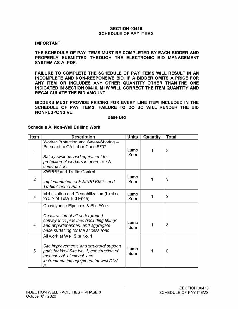
THE SCHEDULE OF PAY ITEMS MUST BE COMPLETED BY EACH BIDDER AND PROPERLY SUBMITTED THROUGH THE ELECTRONIC BID MANAGEMENT SYSTEM AS A .PDF. FAILURE TO COMPLETE THE SCHEDULE OF PAY ITEMS WILL RESULT IN AN INCOMPLETE AND NON-RESPONSIVE BID. IF A BIDDER OMITS A PRICE FOR ANY ITEM OR INCLUDES ANY OTHER QUANTITY OTHER THAN THE ONE INDICATED IN SECTION 00410, M1W WILL CORRECT THE ITEM QUANTITY AND RECALCULATE THE BID AMOUNT.
BIDDERS MUST PROVIDE PRICING FOR EVERY LINE ITEM INCLUDED IN THE SCHEDULE OF PAY ITEMS. FAILURE TO DO SO WILL RENDER THE BID NONRESPONSIVE.
Base Bid Schedule A: Non-Well Drilling Work
Item Description Units Quantity Total
1
Worker Protection and Safety/Shoring –Pursuant to CA Labor Code 6707
Safety systems and equipment for protection of workers in open trench construction.
LumpSum
1
$
2
SWPPP and Traffic Control Implementation of SWPPP BMPs and Traffic Control Plan.
LumpSum
1
$
3
Mobilization and Demobilization (Limited to 5% of Total Bid Price)
LumpSum 1 $
4
Conveyance Pipelines & Site Work Construction of all underground conveyance pipelines (including fittings and appurtenances) and aggregate base surfacing for the access road
LumpSum
1
$
5
All work at Well Site No. 1 Site improvements and structural support pads for Well Site No. 1; construction of mechanical, electrical, and instrumentation equipment for well DIW-3.
LumpSum
1
$
SECTION 00410SCHEDULE OF PAY ITEMS
2 INJECTION WELL FACILITIES – PHASE 3 October 6th, 2020
Item Description Units Quantity Total
6
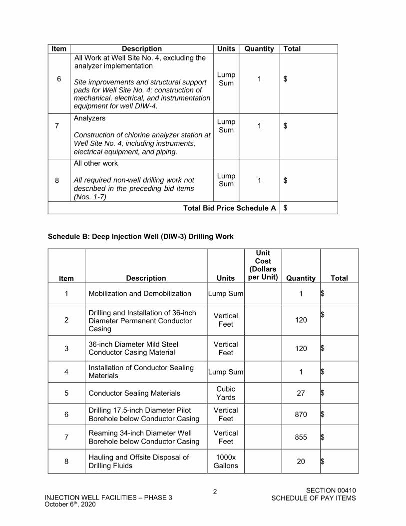
All Work at Well Site No. 4, excluding the analyzer implementation Site improvements and structural support pads for Well Site No. 4; construction of mechanical, electrical, and instrumentation equipment for well DIW-4.
LumpSum
1
$
7
Analyzers Construction of chlorine analyzer station at Well Site No. 4, including instruments, electrical equipment, and piping.
LumpSum
1 $
8
All other work All required non-well drilling work not described in the preceding bid items (Nos. 1-7)
LumpSum
1
$
Total Bid Price Schedule A $
Schedule B: Deep Injection Well (DIW-3) Drilling Work
Item
Description
Units
UnitCost
(Dollars per Unit)
Quantity
Total
1 Mobilization and Demobilization Lump Sum
1 $
2 Drilling and Installation of 36-inch Diameter Permanent Conductor Casing
Vertical Feet
120
$
3 36-inch Diameter Mild Steel Conductor Casing Material
Vertical Feet
120
$
4 Installation of Conductor Sealing Materials Lump Sum
1
$
5 Conductor Sealing Materials Cubic Yards
27
$
6 Drilling 17.5-inch Diameter Pilot Borehole below Conductor Casing
Vertical Feet
870
$
7 Reaming 34-inch Diameter Well Borehole below Conductor Casing
Vertical Feet
855 $
8 Hauling and Offsite Disposal of Drilling Fluids
1000x Gallons
20 $
SECTION 00410SCHEDULE OF PAY ITEMS
3 INJECTION WELL FACILITIES – PHASE 3 October 6th, 2020
Item
Description
Units
UnitCost
(Dollars per Unit)
Quantity
Total
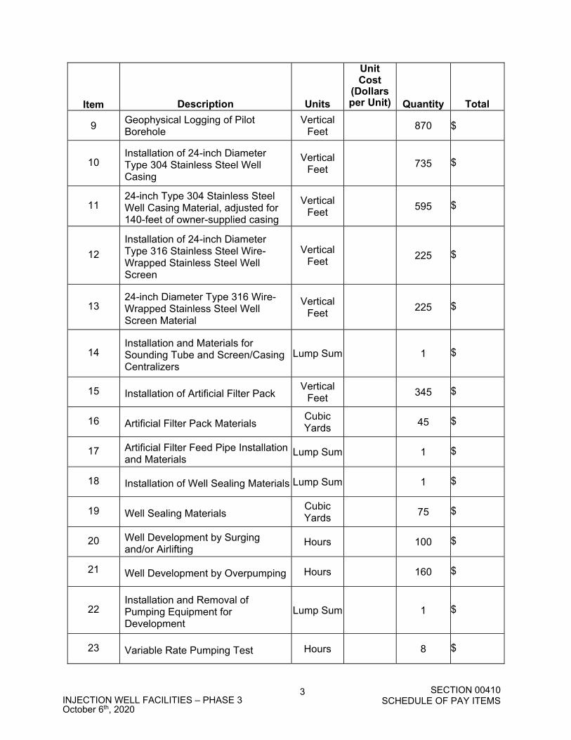
9 Geophysical Logging of Pilot Borehole
Vertical Feet
870 $
10 Installation of 24-inch Diameter Type 304 Stainless Steel Well Casing
Vertical Feet
735 $
11 24-inch Type 304 Stainless Steel Well Casing Material, adjusted for 140-feet of owner-supplied casing
Vertical Feet
595 $
12
Installation of 24-inch Diameter Type 316 Stainless Steel Wire-Wrapped Stainless Steel Well Screen
Vertical Feet
225 $
13 24-inch Diameter Type 316 Wire-Wrapped Stainless Steel Well Screen Material
Vertical Feet
225 $
14 Installation and Materials for Sounding Tube and Screen/Casing Centralizers
Lump Sum
1 $
15 Installation of Artificial Filter Pack Vertical
Feet
345 $
16 Artificial Filter Pack Materials Cubic Yards
45 $
17 Artificial Filter Feed Pipe Installation and Materials
Lump Sum
1 $
18 Installation of Well Sealing Materials Lump Sum
1 $
19 Well Sealing Materials Cubic Yards
75 $
20 Well Development by Surging and/or Airlifting
Hours
100 $
21
Well Development by Overpumping Hours
160 $
22 Installation and Removal of Pumping Equipment for Development
Lump Sum
1 $
23 Variable Rate Pumping Test Hours
8 $
SECTION 00410SCHEDULE OF PAY ITEMS
4 INJECTION WELL FACILITIES – PHASE 3 October 6th, 2020
Item
Description
Units
UnitCost
(Dollars per Unit)
Quantity
Total
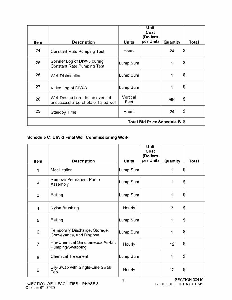
24 Constant Rate Pumping Test Hours
24 $
25 Spinner Log of DIW-3 during Constant Rate Pumping Test
Lump Sum
1 $
26 Well Disinfection Lump Sum
1 $
27 Video Log of DIW-3 Lump Sum
1 $
28 Well Destruction - In the event of unsuccessful borehole or failed well
Vertical Feet
990 $
29 Standby Time Hours
24 $
Total Bid Price Schedule B $
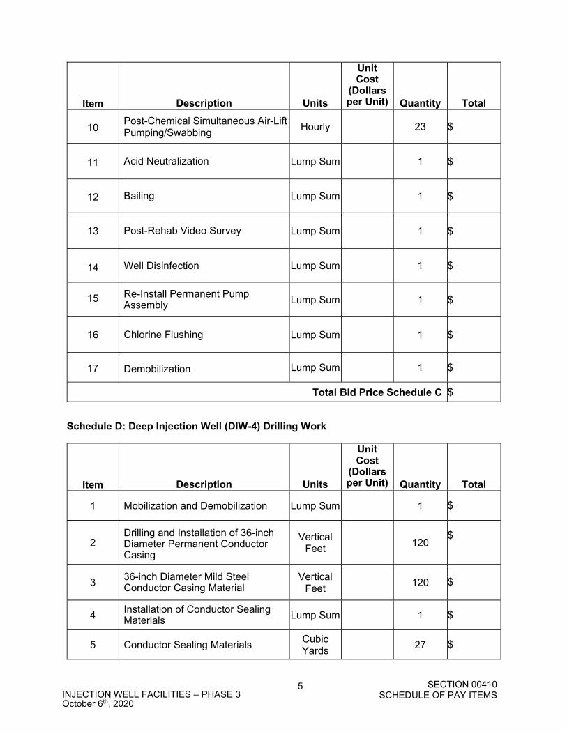
Schedule C: DIW-3 Final Well Commissioning Work
Item
Description
Units
UnitCost
(Dollars per Unit)
Quantity
Total
1 Mobilization Lump Sum 1 $
2
Remove Permanent Pump Assembly
Lump Sum 1 $
3 Bailing Lump Sum 1
$
4 Nylon Brushing Hourly 2
$
5 Bailing Lump Sum 1
$
6 Temporary Discharge, Storage, Conveyance, and Disposal
Lump Sum 1 $
7 Pre-Chemical Simultaneous Air-Lift Pumping/Swabbing
Hourly 12 $
8 Chemical Treatment Lump Sum 1
$
9
Dry-Swab with Single-Line Swab Tool Hourly 12
$
SECTION 00410SCHEDULE OF PAY ITEMS
5 INJECTION WELL FACILITIES – PHASE 3 October 6th, 2020
Item
Description
Units
UnitCost
(Dollars per Unit)
Quantity
Total
10 Post-Chemical Simultaneous Air-Lift Pumping/Swabbing
Hourly 23 $
11 Acid Neutralization Lump Sum 1
$
12 Bailing Lump Sum 1
$
13 Post-Rehab Video Survey Lump Sum 1
$
14 Well Disinfection Lump Sum 1
$
15 Re-Install Permanent Pump
Assembly Lump Sum 1 $
16 Chlorine Flushing Lump Sum 1 $
17 Demobilization Lump Sum 1
$
Total Bid Price Schedule C $ Schedule D: Deep Injection Well (DIW-4) Drilling Work
Item
Description
Units
UnitCost
(Dollars per Unit)
Quantity
Total
1 Mobilization and Demobilization Lump Sum
1 $
2 Drilling and Installation of 36-inch Diameter Permanent Conductor Casing
Vertical Feet
120
$
3 36-inch Diameter Mild Steel Conductor Casing Material
Vertical Feet
120
$
4 Installation of Conductor Sealing Materials Lump Sum
1
$
5 Conductor Sealing Materials Cubic Yards
27
$
SECTION 00410SCHEDULE OF PAY ITEMS
6 INJECTION WELL FACILITIES – PHASE 3 October 6th, 2020
Item
Description
Units
UnitCost
(Dollars per Unit)
Quantity
Total
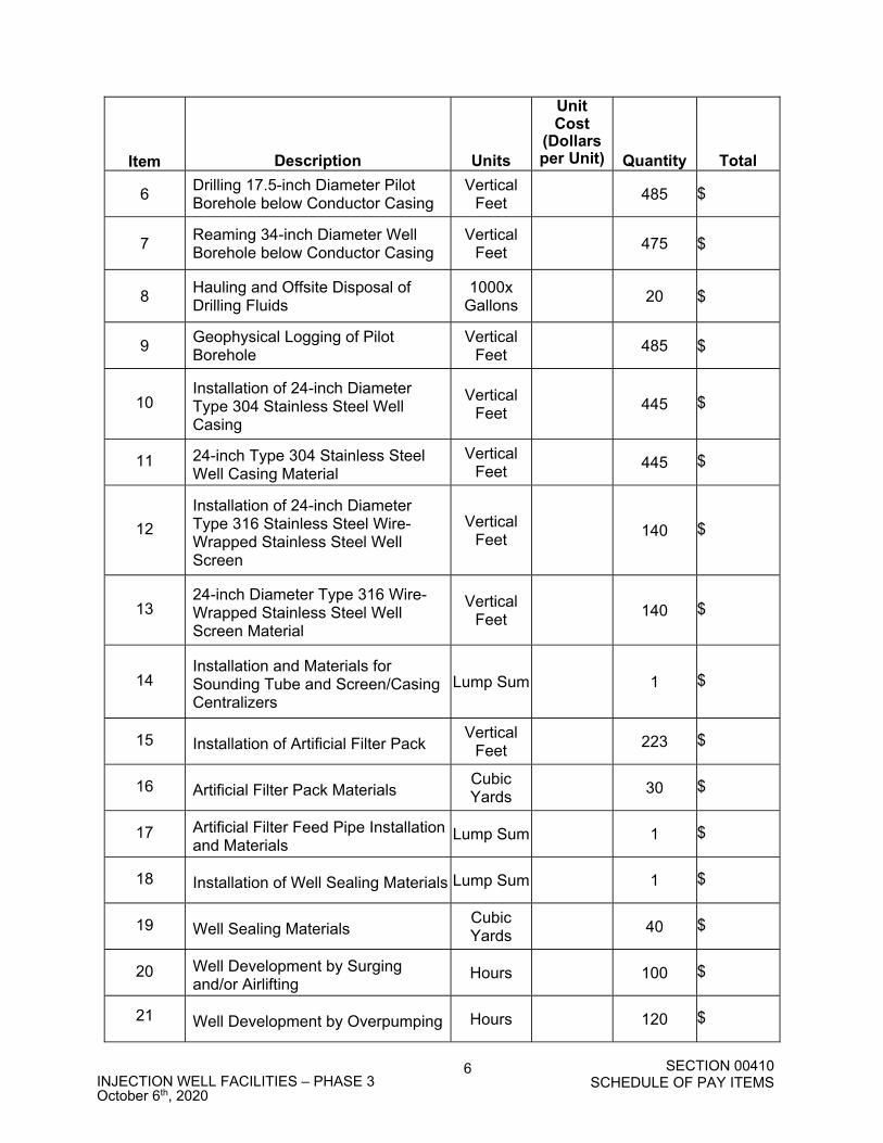
6 Drilling 17.5-inch Diameter Pilot Borehole below Conductor Casing
Vertical Feet
485
$
7 Reaming 34-inch Diameter Well Borehole below Conductor Casing
Vertical Feet
475 $
8 Hauling and Offsite Disposal of Drilling Fluids
1000x Gallons
20 $
9 Geophysical Logging of Pilot Borehole
Vertical Feet
485 $
10 Installation of 24-inch Diameter Type 304 Stainless Steel Well Casing
Vertical Feet
445 $
11 24-inch Type 304 Stainless Steel Well Casing Material
Vertical Feet
445 $
12
Installation of 24-inch Diameter Type 316 Stainless Steel Wire-Wrapped Stainless Steel Well Screen
Vertical Feet
140 $
13 24-inch Diameter Type 316 Wire-Wrapped Stainless Steel Well Screen Material
Vertical Feet
140 $
14 Installation and Materials for Sounding Tube and Screen/Casing Centralizers
Lump Sum
1 $
15 Installation of Artificial Filter Pack Vertical
Feet
223 $
16 Artificial Filter Pack Materials Cubic Yards
30 $
17 Artificial Filter Feed Pipe Installation and Materials
Lump Sum
1 $
18 Installation of Well Sealing Materials Lump Sum
1 $
19 Well Sealing Materials Cubic Yards
40 $
20 Well Development by Surging and/or Airlifting
Hours
100 $
21
Well Development by Overpumping Hours
120 $
SECTION 00410SCHEDULE OF PAY ITEMS
7 INJECTION WELL FACILITIES – PHASE 3 October 6th, 2020
Item
Description
Units
UnitCost
(Dollars per Unit)
Quantity
Total
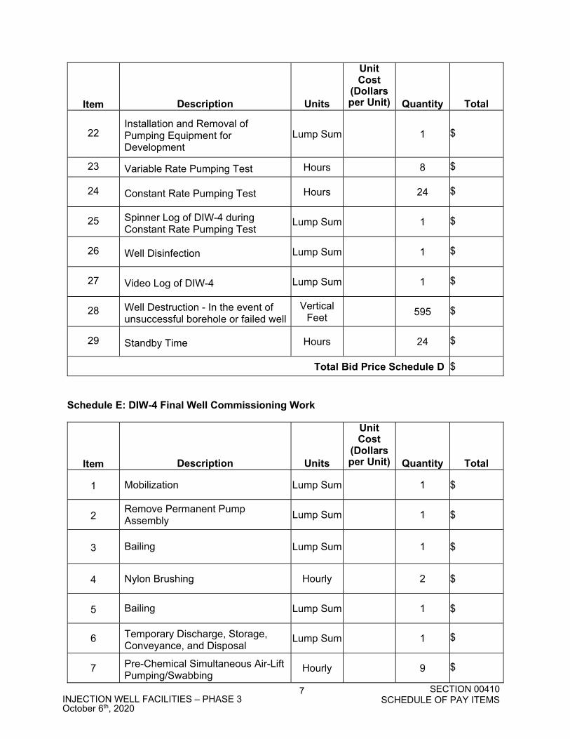
22 Installation and Removal of Pumping Equipment for Development
Lump Sum
1 $
23 Variable Rate Pumping Test Hours 8 $
24 Constant Rate Pumping Test Hours
24 $
25 Spinner Log of DIW-4 during Constant Rate Pumping Test
Lump Sum
1 $
26 Well Disinfection Lump Sum
1 $
27 Video Log of DIW-4 Lump Sum
1 $
28 Well Destruction - In the event of unsuccessful borehole or failed well
Vertical Feet
595 $
29 Standby Time Hours
24 $
Total Bid Price Schedule D $
Schedule E: DIW-4 Final Well Commissioning Work
Item
Description
Units
UnitCost
(Dollars per Unit)
Quantity
Total
1 Mobilization Lump Sum 1 $
2
Remove Permanent Pump Assembly
Lump Sum 1 $
3 Bailing Lump Sum 1
$
4 Nylon Brushing Hourly 2
$
5 Bailing Lump Sum 1
$
6 Temporary Discharge, Storage, Conveyance, and Disposal
Lump Sum 1 $
7 Pre-Chemical Simultaneous Air-Lift Pumping/Swabbing
Hourly 9 $
SECTION 00410SCHEDULE OF PAY ITEMS
8 INJECTION WELL FACILITIES – PHASE 3 October 6th, 2020
Item
Description
Units
UnitCost
(Dollars per Unit)
Quantity
Total
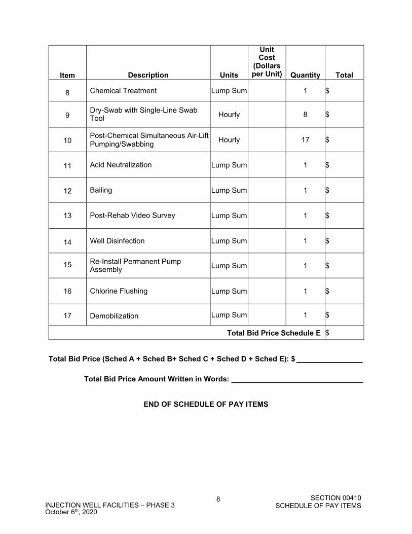
8 Chemical Treatment Lump Sum 1 $
9
Dry-Swab with Single-Line Swab Tool Hourly 8
$
10
Post-Chemical Simultaneous Air-Lift Pumping/Swabbing
Hourly 17 $
11 Acid Neutralization Lump Sum 1
$
12 Bailing Lump Sum 1
$
13 Post-Rehab Video Survey Lump Sum 1
$
14 Well Disinfection Lump Sum 1
$
15 Re-Install Permanent Pump
Assembly Lump Sum 1 $
16 Chlorine Flushing Lump Sum 1 $
17 Demobilization Lump Sum 1
$
Total Bid Price Schedule E $ Total Bid Price (Sched A + Sched B+ Sched C + Sched D + Sched E): $
Total Bid Price Amount Written in Words:
END OF SCHEDULE OF PAY ITEMS
1668012*05 INJECTION WELL FACILITIES – PHASE 3
40 60 20 - 1 Control Strategies October 6th, 2020
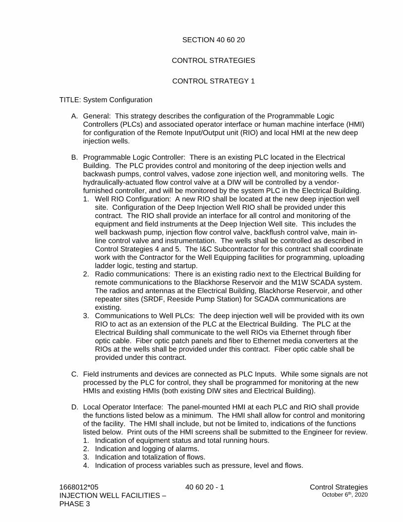
SECTION 40 60 20
CONTROL STRATEGIES
CONTROL STRATEGY 1 TITLE: System Configuration
A. General: This strategy describes the configuration of the Programmable Logic Controllers (PLCs) and associated operator interface or human machine interface (HMI) for configuration of the Remote Input/Output unit (RIO) and local HMI at the new deep injection wells.
B. Programmable Logic Controller: There is an existing PLC located in the Electrical Building. The PLC provides control and monitoring of the deep injection wells and backwash pumps, control valves, vadose zone injection well, and monitoring wells. The hydraulically-actuated flow control valve at a DIW will be controlled by a vendor-furnished controller, and will be monitored by the system PLC in the Electrical Building. 1. Well RIO Configuration: A new RIO shall be located at the new deep injection well
site. Configuration of the Deep Injection Well RIO shall be provided under this contract. The RIO shall provide an interface for all control and monitoring of the equipment and field instruments at the Deep Injection Well site. This includes the well backwash pump, injection flow control valve, backflush control valve, main in-line control valve and instrumentation. The wells shall be controlled as described in Control Strategies 4 and 5. The I&C Subcontractor for this contract shall coordinate work with the Contractor for the Well Equipping facilities for programming, uploading ladder logic, testing and startup.
2. Radio communications: There is an existing radio next to the Electrical Building for remote communications to the Blackhorse Reservoir and the M1W SCADA system. The radios and antennas at the Electrical Building, Blackhorse Reservoir, and other repeater sites (SRDF, Reeside Pump Station) for SCADA communications are existing.
3. Communications to Well PLCs: The deep injection well will be provided with its own RIO to act as an extension of the PLC at the Electrical Building. The PLC at the Electrical Building shall communicate to the well RIOs via Ethernet through fiber optic cable. Fiber optic patch panels and fiber to Ethernet media converters at the RIOs at the wells shall be provided under this contract. Fiber optic cable shall be provided under this contract.
C. Field instruments and devices are connected as PLC Inputs. While some signals are not processed by the PLC for control, they shall be programmed for monitoring at the new HMIs and existing HMIs (both existing DIW sites and Electrical Building).
D. Local Operator Interface: The panel-mounted HMI at each PLC and RIO shall provide the functions listed below as a minimum. The HMI shall allow for control and monitoring of the facility. The HMI shall include, but not be limited to, indications of the functions listed below. Print outs of the HMI screens shall be submitted to the Engineer for review. 1. Indication of equipment status and total running hours. 2. Indication and logging of alarms. 3. Indication and totalization of flows. 4. Indication of process variables such as pressure, level and flows.
Control Strategies October 6th, 2020
40 60 20 - 2 1668012*05 INJECTION WELL FACILITIES,
PHASE 3
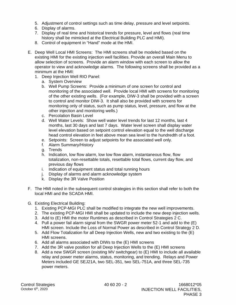
5. Adjustment of control settings such as time delay, pressure and level setpoints. 6. Display of alarms. 7. Display of real time and historical trends for pressure, level and flows (real time
history shall be mimicked at the Electrical Building PLC and HMI). 8. Control of equipment in “Hand” mode at the HMI.
E. Deep Well Local HMI Screens: The HMI screens shall be modeled based on the existing HMI for the existing injection well facilities. Provide an overall Main Menu to allow selection of screens. Provide an alarm window with each screen to allow the operator to view and acknowledge alarms. The following screens shall be provided as a minimum at the HMI: 1. Deep Injection Well RIO Panel:
a. System Overview b. Well Pump Screens: Provide a minimum of one screen for control and
monitoring of the associated well. Provide local HMI with screens for monitoring of the other existing wells. (For example, DIW-3 shall be provided with a screen to control and monitor DIW-3. It shall also be provided with screens for monitoring only of status, such as pump status, level, pressure, and flow at the other injection and monitoring wells.)
c. Percolation Basin Level d. Well Water Levels: Show well water level trends for last 12 months, last 4
months, last 30 days and last 7 days. Water level screen shall display water level elevation based on setpoint control elevation equal to the well discharge head control elevation in feet above mean sea level to the hundredth of a foot.
e. Setpoints: Screen to adjust setpoints for the associated well only. f. Alarm Summary/History g. Trends h. Indication, low flow alarm, low low flow alarm, instantaneous flow, flow
totalization, non-resettable totals, resettable total flows, current day flow, and previous day flows
i. Indication of equipment status and total running hours j. Display of alarms and alarm acknowledge system k. Display the 3R Valve Position
F. The HMI noted in the subsequent control strategies in this section shall refer to both the
local HMI and the SCADA HMI.
G. Existing Electrical Building: 1. Existing PCP-MGI PLC shall be modified to integrate the new well improvements. 2. The existing PCP-MGI HMI shall be updated to include the new deep injection wells. 3. Add to (E) HMI the motor Runtimes as described in Control Strategies 2 C. 4. Pull a power fail alarm signal from the SWGR power meter 52-1 and add to the (E)
HMI screen. Include the Loss of Normal Power as described in Control Strategy 2 D. 5. Add Flow Totalization for all Deep Injection Wells, new and two existing to the (E)
HMI screens. 6. Add all alarms associated with DIWs to the (E) HMI screens 7. Add the 3R valve position for all Deep Injection Wells to the (E) HMI screens 8. Add a new SWGR screen (existing MV switchgear) to (E) HMI to include all available
relay and power meter alarms, status, monitoring, and trending. Relays and Power Meters included GE SEJ21A, two SEL-351, two SEL-751A, and three SEL-735 power meters.
1668012*05 INJECTION WELL FACILITIES – PHASE 3
40 60 20 - 3 Control Strategies October 6th, 2020
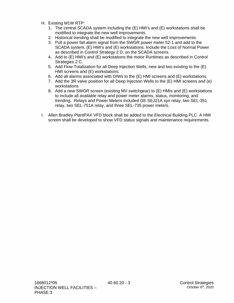
H. Existing M1W RTP: 1. The central SCADA system including the (E) HMI’s and (E) workstations shall be
modified to integrate the new well improvements. 2. Historical trending shall be modified to integrate the new well improvements. 3. Pull a power fail alarm signal from the SWGR power meter 52-1 and add to the
SCADA system, (E) HMI’s and (E) workstations. Include the Loss of Normal Power as described in Control Strategy 2 D. on the SCADA screens.
4. Add to (E) HMI’s and (E) workstations the motor Runtimes as described in Control Strategies 2 C.
5. Add Flow Totalization for all Deep Injection Wells, new and two existing to the (E) HMI screens and (E) workstations.
6. Add all alarms associated with DIWs to the (E) HMI screens and (E) workstations. 7. Add the 3R valve position for all Deep Injection Wells to the (E) HMI screens and (e)
workstations 8. Add a new SWGR screen (existing MV switchgear) to (E) HMIs and (E) workstations
to include all available relay and power meter alarms, status, monitoring, and trending. Relays and Power Meters included GE SEJ21A syn relay, two SEL-351 relay, two SEL-751A relay, and three SEL-735 power meters.
I. Allen Bradley PlantPAX VFD block shall be added to the Electrical Building PLC. A HMI
screen shall be developed to show VFD status signals and maintenance requirements.
Control Strategies October 6th, 2020
40 60 20 - 4 1668012*05 INJECTION WELL FACILITIES,
PHASE 3
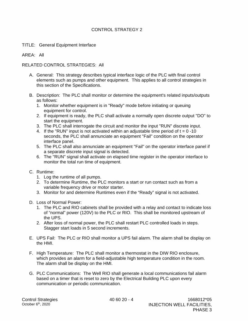
CONTROL STRATEGY 2
TITLE: General Equipment Interface
AREA: All
RELATED CONTROL STRATEGIES: All
A. General: This strategy describes typical interface logic of the PLC with final control elements such as pumps and other equipment. This applies to all control strategies in this section of the Specifications.
B. Description: The PLC shall monitor or determine the equipment's related inputs/outputs as follows: 1. Monitor whether equipment is in "Ready" mode before initiating or queuing
equipment for control. 2. If equipment is ready, the PLC shall activate a normally open discrete output "DO" to
start the equipment. 3. The PLC shall interrogate the circuit and monitor the input "RUN" discrete input. 4. If the "RUN" input is not activated within an adjustable time period of t = 0 -10
seconds, the PLC shall annunciate an equipment "Fail" condition on the operator interface panel.
5. The PLC shall also annunciate an equipment "Fail" on the operator interface panel if a separate discrete input signal is detected.
6. The "RUN" signal shall activate on elapsed time register in the operator interface to monitor the total run time of equipment.
C. Runtime: 1. Log the runtime of all pumps. 2. To determine Runtime, the PLC monitors a start or run contact such as from a
variable frequency drive or motor starter. 3. Monitor for and determine Runtimes even if the “Ready” signal is not activated.
D. Loss of Normal Power: 1. The PLC and RIO cabinets shall be provided with a relay and contact to indicate loss
of “normal” power (120V) to the PLC or RIO. This shall be monitored upstream of the UPS.
2. After loss of normal power, the PLC shall restart PLC controlled loads in steps. Stagger start loads in 5 second increments.
E. UPS Fail: The PLC or RIO shall monitor a UPS fail alarm. The alarm shall be display on the HMI.
F. High Temperature: The PLC shall monitor a thermostat in the DIW RIO enclosure, which provides an alarm for a field-adjustable high temperature condition in the room. The alarm shall be display on the HMI.
G. PLC Communications: The Well RIO shall generate a local communications fail alarm based on a timer that is reset to zero by the Electrical Building PLC upon every communication or periodic communication.

1668012*05 INJECTION WELL FACILITIES – PHASE 3
40 60 20 - 5 Control Strategies October 6th, 2020
H. Panel Intrusion Alarm: The RIO panel door switch shall be monitored by the PLC. Authorized personnel shall be provided with an override key (Operator input at the local HMI) to disarm a panel intrusion alarm generated by the door switch.
Control Strategies October 6th, 2020
40 60 20 - 6 1668012*05 INJECTION WELL FACILITIES,
PHASE 3
CONTROL STRATEGY 3
TITLE: Alarm System RELATED EQUIPMENT AND CONTROL STRATEGIES: All
A. General: This strategy describes the monitoring and display of alarm conditions. The alarm conditions can be 1) Discrete input and 2) Derived.
B. Description:
1. Discrete Input: Whenever a discrete input alarm is detected, the PLC shall annunciate an alarm after an adjustable delay of 0 - 5 seconds.
2. Derived Alarms: A derived alarm consists of monitoring of analog inputs and/or logic derivation within control strategies. The PLC monitors these events and produce alarms after an adjustable delay of 0 - 5 seconds. Setting of alarm setpoint shall be available on the operator interface.
3. Instrument Analog Signal out of range: The PLC shall monitor 4-20mA analog signals from instrumentation such as level and pressure transmitters and flowmeters that provide continuous process signal monitoring. The PLC shall annunciate an “invalid signal” or “out of range” alarm when the signal is above or below the calibrated instrument range.
C. Alarm Sequence: The PLC programs shall execute alarms as follows:
1. Upon the activation of an alarm, a flashing indication and alarm text message shall be displayed on the operator interface.
2. An “Alarm Acknowledge” button at the operator interface shall acknowledge the alarm and the alarm message shall stay steady.
3. An “Alarm Reset” button shall remove the alarm message.
1668012*05 INJECTION WELL FACILITIES – PHASE 3
40 60 20 - 7 Control Strategies October 6th, 2020
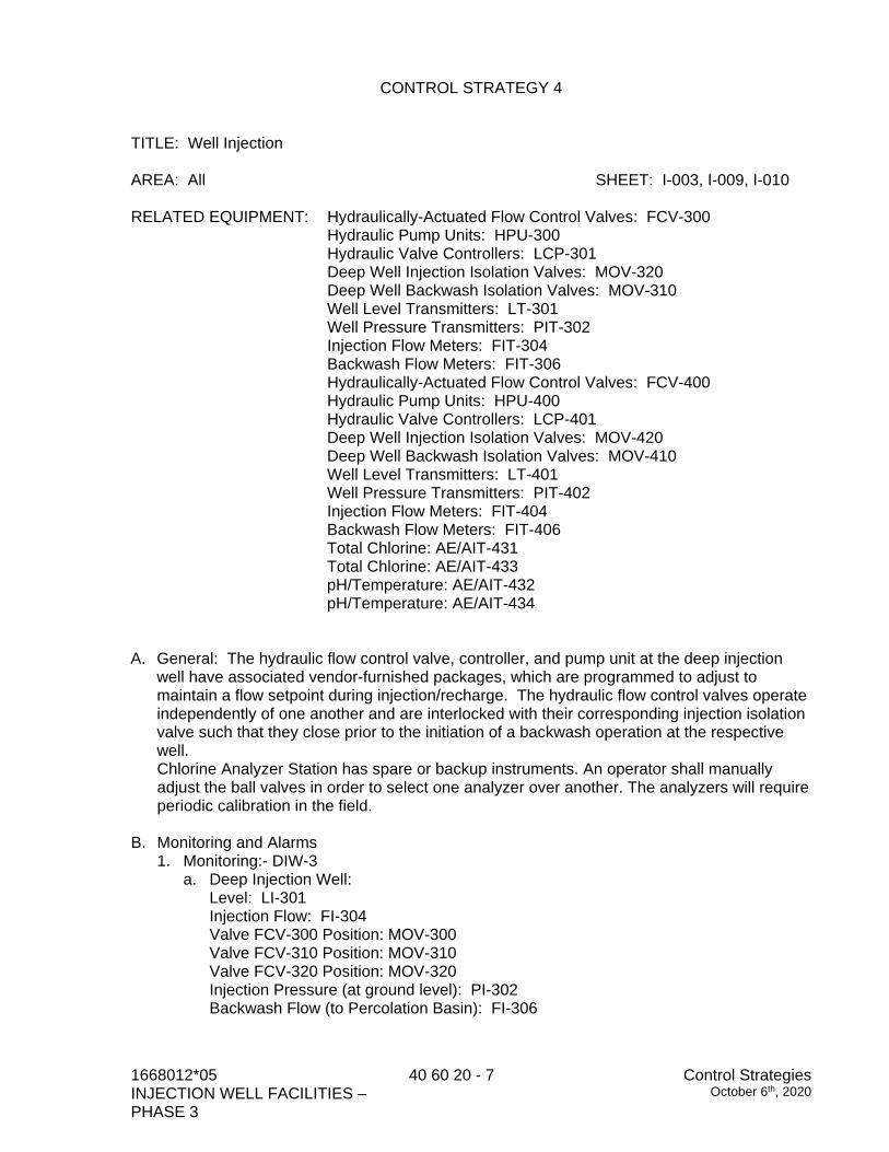
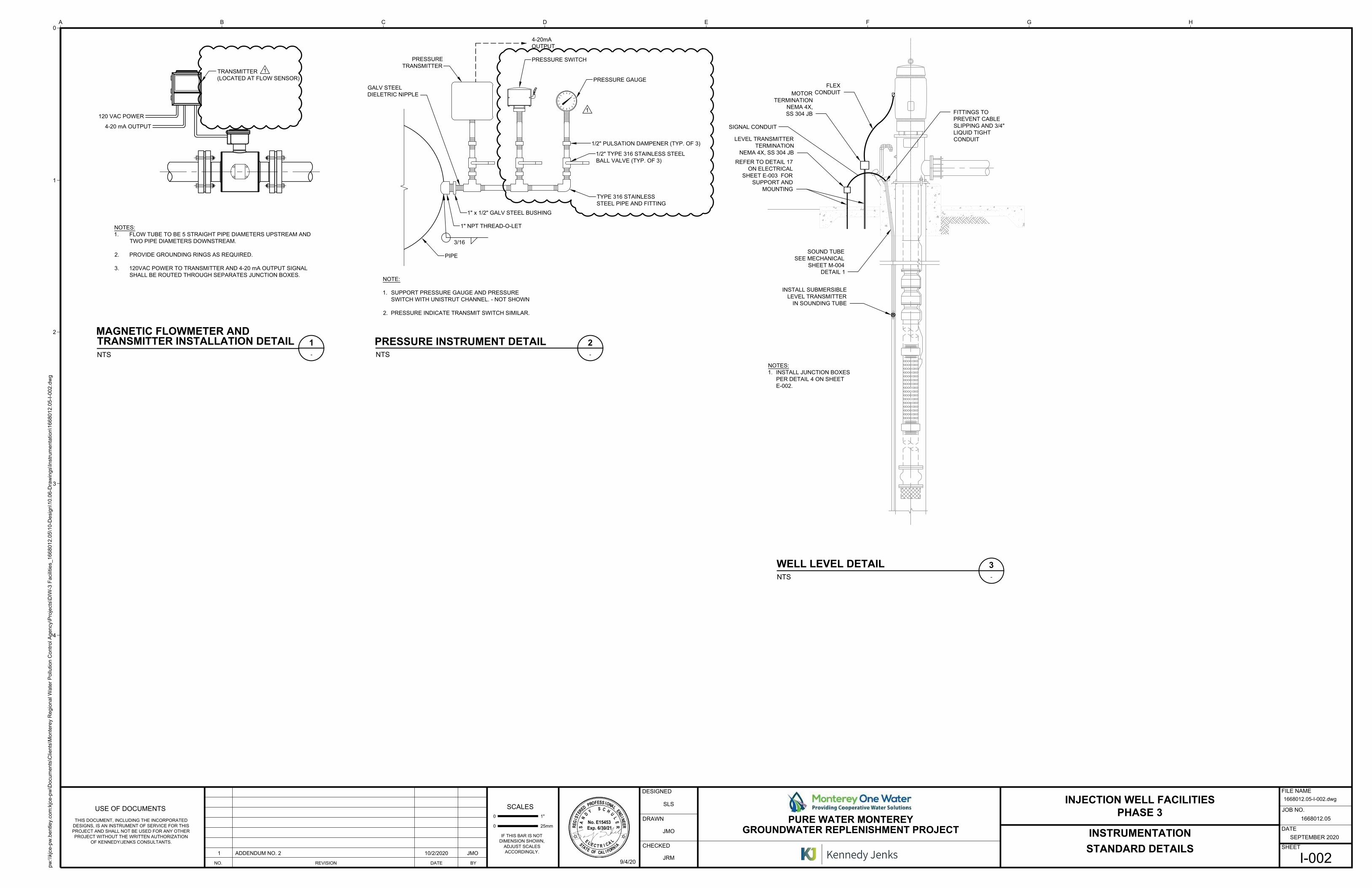
CONTROL STRATEGY 4 TITLE: Well Injection AREA: All SHEET: I-003, I-009, I-010 RELATED EQUIPMENT: Hydraulically-Actuated Flow Control Valves: FCV-300 Hydraulic Pump Units: HPU-300 Hydraulic Valve Controllers: LCP-301 Deep Well Injection Isolation Valves: MOV-320 Deep Well Backwash Isolation Valves: MOV-310 Well Level Transmitters: LT-301 Well Pressure Transmitters: PIT-302 Injection Flow Meters: FIT-304 Backwash Flow Meters: FIT-306 Hydraulically-Actuated Flow Control Valves: FCV-400 Hydraulic Pump Units: HPU-400 Hydraulic Valve Controllers: LCP-401 Deep Well Injection Isolation Valves: MOV-420 Deep Well Backwash Isolation Valves: MOV-410 Well Level Transmitters: LT-401 Well Pressure Transmitters: PIT-402 Injection Flow Meters: FIT-404 Backwash Flow Meters: FIT-406 Total Chlorine: AE/AIT-431 Total Chlorine: AE/AIT-433 pH/Temperature: AE/AIT-432 pH/Temperature: AE/AIT-434 A. General: The hydraulic flow control valve, controller, and pump unit at the deep injection
well have associated vendor-furnished packages, which are programmed to adjust to maintain a flow setpoint during injection/recharge. The hydraulic flow control valves operate independently of one another and are interlocked with their corresponding injection isolation valve such that they close prior to the initiation of a backwash operation at the respective well. Chlorine Analyzer Station has spare or backup instruments. An operator shall manually adjust the ball valves in order to select one analyzer over another. The analyzers will require periodic calibration in the field.
B. Monitoring and Alarms 1. Monitoring:- DIW-3
a. Deep Injection Well: Level: LI-301 Injection Flow: FI-304 Valve FCV-300 Position: MOV-300 Valve FCV-310 Position: MOV-310 Valve FCV-320 Position: MOV-320 Injection Pressure (at ground level): PI-302 Backwash Flow (to Percolation Basin): FI-306
Control Strategies October 6th, 2020
40 60 20 - 8 1668012*05 INJECTION WELL FACILITIES,
PHASE 3
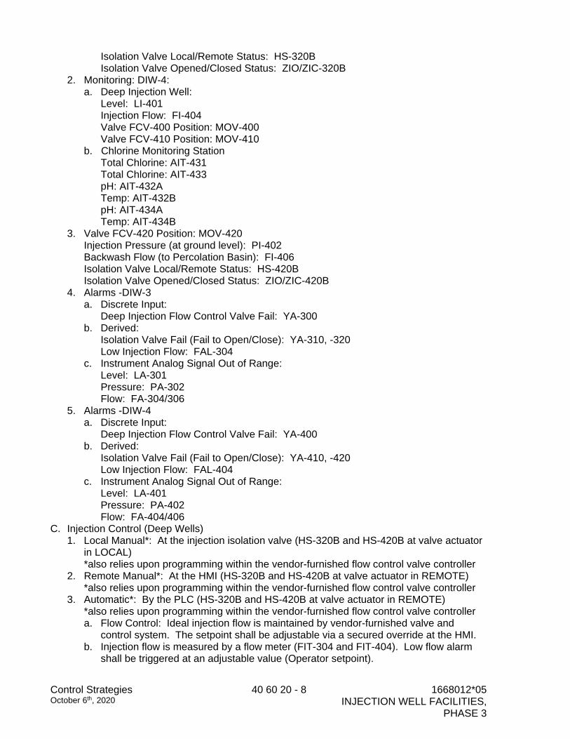
Isolation Valve Local/Remote Status: HS-320B Isolation Valve Opened/Closed Status: ZIO/ZIC-320B
2. Monitoring: DIW-4: a. Deep Injection Well:
Level: LI-401 Injection Flow: FI-404 Valve FCV-400 Position: MOV-400 Valve FCV-410 Position: MOV-410
b. Chlorine Monitoring Station Total Chlorine: AIT-431 Total Chlorine: AIT-433 pH: AIT-432A Temp: AIT-432B pH: AIT-434A Temp: AIT-434B
3. Valve FCV-420 Position: MOV-420 Injection Pressure (at ground level): PI-402 Backwash Flow (to Percolation Basin): FI-406 Isolation Valve Local/Remote Status: HS-420B Isolation Valve Opened/Closed Status: ZIO/ZIC-420B
4. Alarms -DIW-3 a. Discrete Input:
Deep Injection Flow Control Valve Fail: YA-300 b. Derived:
Isolation Valve Fail (Fail to Open/Close): YA-310, -320 Low Injection Flow: FAL-304
c. Instrument Analog Signal Out of Range: Level: LA-301 Pressure: PA-302 Flow: FA-304/306
5. Alarms -DIW-4 a. Discrete Input:
Deep Injection Flow Control Valve Fail: YA-400 b. Derived:
Isolation Valve Fail (Fail to Open/Close): YA-410, -420 Low Injection Flow: FAL-404
c. Instrument Analog Signal Out of Range: Level: LA-401 Pressure: PA-402 Flow: FA-404/406
C. Injection Control (Deep Wells) 1. Local Manual*: At the injection isolation valve (HS-320B and HS-420B at valve actuator
in LOCAL) *also relies upon programming within the vendor-furnished flow control valve controller
2. Remote Manual*: At the HMI (HS-320B and HS-420B at valve actuator in REMOTE) *also relies upon programming within the vendor-furnished flow control valve controller
3. Automatic*: By the PLC (HS-320B and HS-420B at valve actuator in REMOTE) *also relies upon programming within the vendor-furnished flow control valve controller a. Flow Control: Ideal injection flow is maintained by vendor-furnished valve and
control system. The setpoint shall be adjustable via a secured override at the HMI. b. Injection flow is measured by a flow meter (FIT-304 and FIT-404). Low flow alarm
shall be triggered at an adjustable value (Operator setpoint).
1668012*05 INJECTION WELL FACILITIES – PHASE 3
40 60 20 - 9 Control Strategies October 6th, 2020
c. Injection pressure (at ground level) is measured by a pressure transmitter (PIT-302 and PIT-402). The flow control valve shall close at a configurable low pressure setpoint.
d. Well level is measured by a level transmitter (LT-301 and LT-401). The flow control valve shall close at a configurable high water level setpoint.
D. Interlocks: 1. Deep Well Injection Flow Control Valves: Shall close when the corresponding deep well
injection isolation valve closes.
Control Strategies October 6th, 2020
40 60 20 - 10 1668012*05 INJECTION WELL FACILITIES,
PHASE 3
CONTROL STRATEGY 5 TITLE: Deep Well Backwash Pump Control AREA: All SHEET: I-003, I-009, I-010 RELATED EQUIPMENT: Hydraulically-Actuated Flow Control Valves: FCV-300 Hydraulic Pump Units: HPU-300 Hydraulic Valve Controllers: LCP-301 Deep Well Injection Isolation Valves: MOV-320 Deep Well Backwash Isolation Valves: MOV-310 Well Level Transmitters: LT-301 Well Pressure Transmitters: PIT-302 Well High Pressure Switches: PSH-302 Backwash Flow Meters: FIT-306 Backwash Pumps High Vibration Switches: VT-301A, VT -301B Backwash Pumps High RTDs: TIT-301 Backwash Pumps VFD (Output Contactors): XI-300, YI-301 Hydraulically-Actuated Flow Control Valves: FCV-400 Hydraulic Pump Units: HPU-400 Hydraulic Valve Controllers: LCP-401 Deep Well Injection Isolation Valves: MOV-420 Deep Well Backwash Isolation Valves: MOV-410 Well Level Transmitters: LT-401 Well Pressure Transmitters: PIT-402 Well High Pressure Switches: PSH-402 Backwash Flow Meters: FIT-406 Backwash Pumps High Vibration Switches: VT-401A, VT -401B Backwash Pumps High RTDs: TIT-401 Backwash Pumps VFD (Output Contactors): XI-400, YI-401 A. General: The deep injection well shall be equipped with one deep well turbine pump and
motor for backwash operations. Backwashes will occur weekly on each deep injection well, with only one well backwashed at one time. One variable frequency drive (VFD) controls all backwash pumps. The VFD can accommodate up to four (4) full-voltage bypass contactors, one for each planned deep injection well. The deep well shall be equipped with an electrically actuated backwash isolation valve (flow to Percolation Basin), an electrically actuated injection isolation valve, and an in-line check valve assembly on each the injection piping and the backwash piping. 1. The injection isolation valve shall be open when the well is in injection mode (normally
open) and the backwash isolation valve shall be closed when the well is in injection mode (normally closed).
2. In the “AUTO” control mode the backwash pump will be called to run based on a request from the PLC at the Electrical Building. Pump speed will be controlled using a true PID algorithm (proportional, integral, derivative, time constant and setpoint) to maintain a setpoint flow rate within an adjustable deadband setpoint.
B. Monitoring and Alarms
1. Monitoring:- DIW-3
1668012*05 INJECTION WELL FACILITIES – PHASE 3
40 60 20 - 11 Control Strategies October 6th, 2020
a. Deep Injection Wells: Backwash Pump Run Status: XI-300 Backwash Pump E-Stop Status: YI-301 Backwash Pump VFD Remote Status: HS-001A Backwash Pump VFD Speed Indication: SI-001 Level: LI-301 Backwash Pressure: PI-302 Valve FCV-300 Position: MOV-300 Valve FCV-310 Position: MOV-310 Valve FCV-320 Position: MOV-320 Backwash Flow (to Percolation Basin): FI-306 Injection Isolation Valve Local/Remote Status: HS-320B Injection Isolation Valve Opened/Closed Status: ZIO/ZIC-320B Backwash Isolation Valve Local/Remote Status: HS-310B Backwash Isolation Valve Opened/Closed Status: ZIO/ZIC-310B
b. Deep Monitoring Wells: Level: LI-305
c. Percolation Pond: Level: LI-151
d. Surge Tank: Differential Pressure: DPI-150
2. Monitoring:- DIW-4 a. Deep Injection Wells:
Backwash Pump Run Status: XI-400 Backwash Pump E-Stop Status: YI-401 Backwash Pump VFD Remote Status: HS-001A Backwash Pump VFD Speed Indication: SI-001 Level: LI-401 Backwash Pressure: PI-402 Valve FCV-400 Position: MOV-400 Valve FCV-410 Position: MOV-410 Valve FCV-420 Position: MOV-420 Backwash Flow (to Percolation Basin): FI-406 Injection Isolation Valve Local/Remote Status: HS-420B Injection Isolation Valve Opened/Closed Status: ZIO/ZIC-420B Backwash Isolation Valve Local/Remote Status: HS-410B Backwash Isolation Valve Opened/Closed Status: ZIO/ZIC-410B
b. Deep Monitoring Wells: Level: LI-405
c. Percolation Pond: Level: LI-151
d. Surge Tank: Differential Pressure: DPI-150
3. Alarms -DIW-3
a. Discrete Input: VFD Fail: YA-001 Pump E-Stop: YA-301 Pump High Bearing Vibration Shutdown: VAH-301A Pump High Shaft Vibration Shutdown: VAH-301B Pump High Temperature Shutdown: TAH-301 Pump High Discharge Pressure Shutdown: PAH-302B
Control Strategies October 6th, 2020
40 60 20 - 12 1668012*05 INJECTION WELL FACILITIES,
PHASE 3
Percolation Pond High Level Shutdown: LAH-151B Deep Injection Flow Control Valve Fail: YA-300 b. Derived: Well Low Level: LAL-301 Pump High Discharge Pressure Alarm: PAH-302A High/Low Flow: FAH/FAL-306 Percolation Pond High Level Alarm: LAH-151A Isolation Valve Fail (Fail to Open/Close): YA-310, -320 c. Instrument Analog Signal Out of Range: Level: LA-301 Pressure: PA-302, DPA-150 Flow: FA-306
4. Alarms - DIW-4 a. Discrete Input: VFD Fail: YA-001 Pump E-Stop: YA-401 Pump High Bearing Vibration Shutdown: VAH-401A Pump High Shaft Vibration Shutdown: VAH-401B Pump High Temperature Shutdown: TAH-401 Pump High Discharge Pressure Shutdown: PAH-402B Percolation Pond High Level Shutdown: LAH-151B Deep Injection Flow Control Valve Fail: YA-400 b. Derived: Well Low Level: LAL-401 Pump High Discharge Pressure Alarm: PAH-402A High/Low Flow: FAH/FAL-406 Percolation Pond High Level Alarm: LAH-151A Isolation Valve Fail (Fail to Open/Close): YA-410, -420 c. Instrument Analog Signal Out of Range: Level: LA-401 Pressure: PA-402, DPA-150 Flow: FA-406
C. Pump Control: The pump can be started in one of three ways: 1. Local Manual: At the VFD (LOR switch at VFD in LOCAL)
a. Speed shall be manually controlled at the VFD keypad. 2. Remote Manual: At the Electrical Building HMI, local well HMI, or SCADA HMI (LOR
switch at VFD in REMOTE) a. Placing the pump HOA switch on the HMI display in the HAND position initiates
the change from injection mode to backwash mode. b. After initiation of backwash mode is complete (isolation valves changed, as
described in paragraph D), the pump starts if the pump is permitted and not failed. c. Speed shall be controlled manually at the HMI (manual speed entry to sliding scale
bar) 3. Automatic: By the Electrical Building PLC (LOR switch at VFD in REMOTE)
a. Backwash pump starts when initiated by its weekly schedule. The backwash for each well shall run on a weekly schedule. The pump shall ramp up to a flow set point or an automated flow rate modulation based on well level as described in Paragraph E. The pump run time and schedule shall be configurable.
b. Speed shall be adjusted based on a PID loop to maintain the current setpoint. c. Control valve sequence shall be initiated upon pump call to run as described in
Paragraph D, below.
1668012*05 INJECTION WELL FACILITIES – PHASE 3
40 60 20 - 13 Control Strategies October 6th, 2020
D. Control Valve Sequence: Under backwash operations the backwash isolation valve shall
be fully opened and the injection isolation valve shall be fully closed before the backwash pump is called to start. The valves shall open and close based on the sequences below. 1. Valve sequencing: The injection flow control valve shall be called to close. After the
injection flow control valve is closed, the injection isolation valve shall be called to close. After the injection isolation valve is closed, the backwash isolation valve shall be called to open.
2. Pump start permissives: The backwash pump shall not start under the following conditions: a. The backwash isolation valve is not open (initiate a backwash valve alarm) b. The injection isolation valve or injection flow control valve is not closed (initiate an
injection valve alarm) c. One of the other backwash pumps is running. d. The well water level is below a configurable setpoint. e. The percolation basin water level is above a configurable setpoint. f. Pump has been started 3 times within the last hour.
3. Initiate backwash mode: The VFD shall start at minimum speed and the backwash timer shall start (PLC timer, with secured override in the HMI). The PLC shall monitor the backwash pump RUN status. If no RUN condition is detected, the PLC shall initiate an alarm and backwash pump shutdown. The VFD shall maintain minimum speed until a stable flow is established.
4. Pump flow ramp-up (after pump call to run): Once stable flow is established at minimum speed, pump flow shall be increased to the flow setpoint, based on a configurable ramp-up flow schedule. At the desired flow set point, the pump speed shall be maintained based on PID loop control as described in paragraph E.
5. Pump call to stop: When the pump is called to stop, the pump speed shall be reduced until the pump is stopped (pump speed is 0%). The backwash isolation valve shall be closed. After the backwash isolation valve is fully closed, the injection isolation valve shall be called to open after an adjustable time delay. If the backwash isolation valve does not close or the injection isolation valve does not open, a valve alarm shall be initiated.
E. Backwash Pump Automatic Speed Control: The PLC shall adjust the speed of the
backwash pump using PID loop controls to maintain the current setpoint. Automatic speed control shall be based on a single flow setpoint for initial operation. Control setting shall be selectable at the HMI. 1. Flow setpoint control: The flow setpoint shall be preset in the HMI. The PLC shall
initiate a pump call to start. The PLC shall initiate the valve control sequence as described in paragraph D. The PLC shall adjust the pump speed using PID loop control to maintain the desired flow. The flow rate shall have an adjustable deadband setpoint. The flow shall be monitored by a flowmeter on the backwash to percolation basin pipeline.
2. Well level control: If, during the flow setpoint control backwash operation, the well level falls below a configurable setpoint, the backwash control shall change to an automated flow rate modulation. The PLC shall adjust the pump speed using PID loop control to maintain the desired well level. The well level shall have an adjustable deadband setpoint. The flow shall be monitored by a flowmeter at the pump discharge.
F. Backwash Pump Shutdown: The backwash pump shutdown sequence shall be initiated
when any of the conditions listed below occur during the pump startup sequence or during normal operations. The shutdown sequence shall start after an adjustable time delay.
Control Strategies October 6th, 2020
40 60 20 - 14 1668012*05 INJECTION WELL FACILITIES,
PHASE 3
1. VFD Fail (contact closure at VFD). On a VFD Fail condition, the PLC shall attempt to reset and restart the pump. The number of attempts shall be adjustable at the HMI. A VFD Fail alarm shall be initiated to alert the Operator of a VFD lockout.
2. Emergency Stop (pushbutton switch located at each well). On an E-stop condition, the PLC shall initiate control valve sequence as described in paragraph D. The pump shall not restart until the alarm is cleared at the VFD.
3. High pressure, as measured by the pressure transmitter on the main line. High pressure shutdown setpoint shall be adjustable at the HMI.
4. High pressure, as indicated by the pressure switch on the pump discharge. The pressure switch shall be hard-wired to the VFD for pump shutdown at the VFD. The PLC shall initiate control valve sequence as described in paragraph D when the pump is stopped.
5. Low flow, as measured by the flowmeter on the backwash line. Low flow shutdown setpoint shall be adjustable at the HMI. The backwash pump shall be restarted manually by operator input.
6. Low low well water level, as measured by the well level transmitter. Low low well water level shutdown setpoint shall be adjustable at the HMI. The backwash pump shall be restarted manually by operator input.
7. High high percolation basin water level, as measured by the percolation pond level transmitter. High high water level setpoint shall be adjustable at the HMI. The backwash pump shall be restarted manually by operator input.
8. High high percolation basin water level, as indicated by the percolation pond level switch (normally closed contact open at VFD). Percolation pond high high level shall be hard-wired to the VFD for shutdown at the VFD. The PLC shall initiate control valve sequence as described in paragraph D when the pump is stopped. The pump shall not restart until the alarm is cleared at the VFD.
9. Motor overtemperature (normally closed contact open at VFD). Motor overtemperature shall be hard-wired to the VFD for shutdown at the VFD. The PLC shall initiate control valve sequence as described in paragraph D when the pump is stopped. The pump shall not restart until the alarm is cleared at the VFD.
10. Motor high vibration (normally closed contact open at VFD). Motor high vibration shall be hard-wired to the VFD for shutdown at the VFD. The PLC shall initiate control valve sequence as described in paragraph D when the pump is stopped. The pump shall not restart until the alarm is cleared at the VFD.
11. Overload (normally closed contacts open at VFD). Motor overload shall be hard-wired to the VFD for shutdown at the VFD. The PLC shall initiate control valve sequence as described in paragraph D when the pump is stopped. The pump shall not restart until the alarm is cleared at the VFD.
G. Loss of Power: When a loss of power occurs during the pump startup sequence or
backwash operation, the PLC shall not call the pump to start (restart the pump). A pump fail alarm shall be indicated until the backwash isolation valve opens and the injection isolation valve closes. The pump fail alarm shall be cleared when the valves return to normal condition before a pump call to start. 1. Upon loss of power, the flow control valve shall fail in the closed position.
END OF CONTROL STRATEGIES

4
3
2
1
0
0
USE OF DOCUMENTS
25mm
SCALES
1"
CHECKED
DESIGNED
DRAWN
0
Kennedy/Jenks Consultants
DATE
SHEET
FILE NAME
JOB NO.
D E F G HA B C
IF THIS BAR IS NOT
DIMENSION SHOWN,
ADJUST SCALES
ACCORDINGLY.
THIS DOCUMENT, INCLUDING THE INCORPORATED
DESIGNS, IS AN INSTRUMENT OF SERVICE FOR THIS
PROJECT AND SHALL NOT BE USED FOR ANY OTHER
PROJECT WITHOUT THE WRITTEN AUTHORIZATION
OF KENNEDY/JENKS CONSULTANTS.
NO. REVISION DATE BY
1668012.05
PURE WATER MONTEREY
GROUNDWATER REPLENISHMENT PROJECT
INJECTION WELL FACILITIES
PHASE 3
SEPTEMBER 2020
M:\K
JC
I\0
3-D
IW
-3
\D
ra
win
gs\1
66
80
12
05
-C
-0
01
.d
wg
9
/3
0/2
02
0 A
Ste
rb
en
z
(831) 883-4848Salinas, CA 93907-2348
3 Quail Run Circle, Suite 101
9/1/2020
CJM
CJM
AAS
1 ADDENDUM NO. 1 09/25/2020 AAS
2 ADDENDUM NO. 2 10/1/2020 AAS
SWPPP DETAILS 2
C-003
166801205-C-001.DWG
M:\K
JC
I\03-D
IW
-3\D
raw
in
gs\166801205-C
-001.d
wg
, C
003, 9/30/2020 10:32:07 A
M
NTS
TRANSMITTER
(LOCATED AT FLOW SENSOR)
120 VAC POWER
4-20 mA OUTPUT
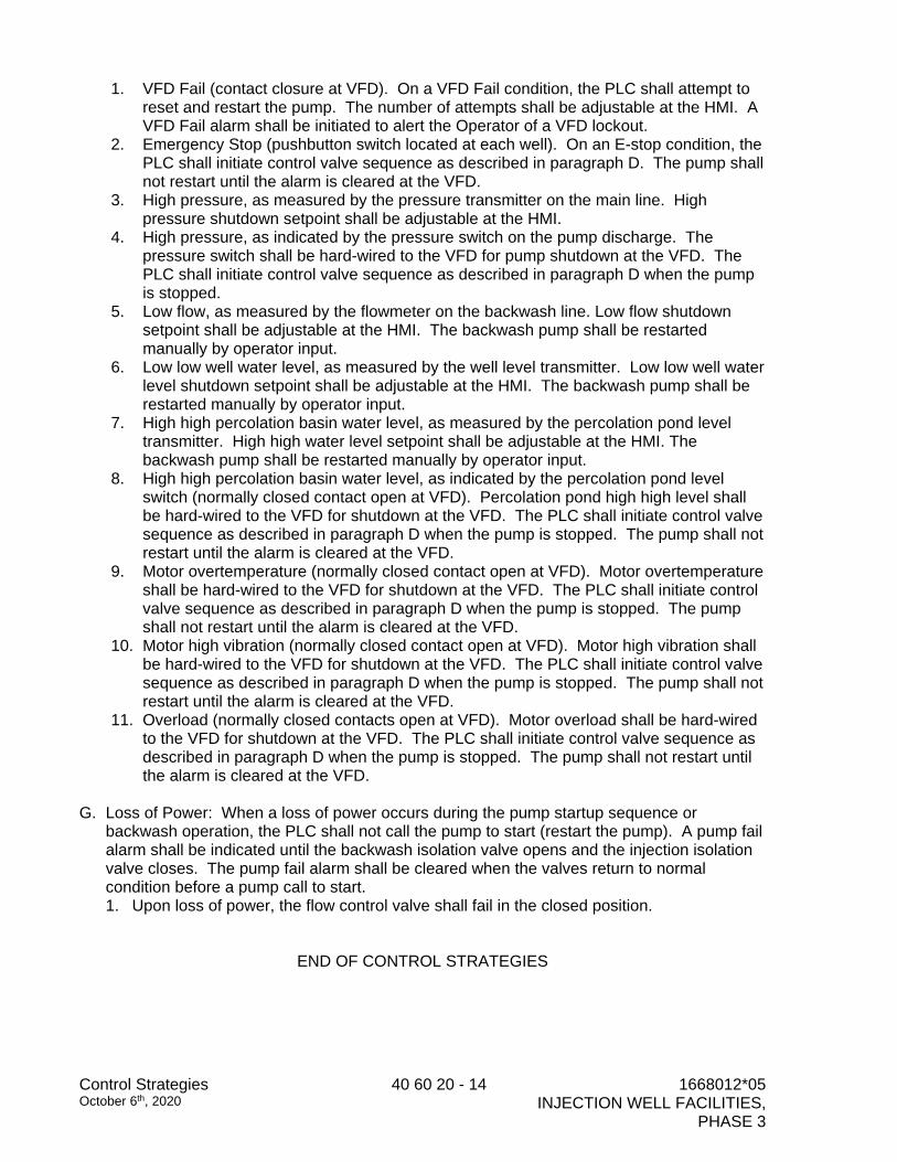
NOTES:
1. FLOW TUBE TO BE 5 STRAIGHT PIPE DIAMETERS UPSTREAM AND
TWO PIPE DIAMETERS DOWNSTREAM.
2. PROVIDE GROUNDING RINGS AS REQUIRED.
3. 120VAC POWER TO TRANSMITTER AND 4-20 mA OUTPUT SIGNAL
SHALL BE ROUTED THROUGH SEPARATES JUNCTION BOXES.
TRANSMITTER INSTALLATION DETAIL
MAGNETIC FLOWMETER AND
1
-
NOTE:
1. SUPPORT PRESSURE GAUGE AND PRESSURE
SWITCH WITH UNISTRUT CHANNEL. - NOT SHOWN
2. PRESSURE INDICATE TRANSMIT SWITCH SIMILAR.
NTS
PRESSURE INSTRUMENT DETAIL2
-
NTS
WELL LEVEL DETAIL3
-
SIGNAL CONDUIT
LEVEL TRANSMITTER
TERMINATION
NEMA 4X, SS 304 JB
FITTINGS TO
PREVENT CABLE
SLIPPING AND 3/4"
LIQUID TIGHT
CONDUIT
REFER TO DETAIL 17
ON ELECTRICAL
SHEET E-003 FOR
SUPPORT AND
MOUNTING
MOTOR
TERMINATION
NEMA 4X,
SS 304 JB
FLEX
CONDUIT
SOUND TUBE
SEE MECHANICAL
SHEET M-004
DETAIL 1
INSTALL SUBMERSIBLE
LEVEL TRANSMITTER
IN SOUNDING TUBE
NOTES:
1. INSTALL JUNCTION BOXES
PER DETAIL 4 ON SHEET
E-002.
3/16
PRESSURE
TRANSMITTER
PRESSURE SWITCH
1" x 1/2" GALV STEEL BUSHING
1" NPT THREAD-O-LET
PIPE
1/2" PULSATION DAMPENER (TYP. OF 3)
1/2" TYPE 316 STAINLESS STEEL
BALL VALVE (TYP. OF 3)
4-20mA
OUTPUT
PRESSURE GAUGE
TYPE 316 STAINLESS
STEEL PIPE AND FITTING
GALV STEEL
DIELETRIC NIPPLE
4
3
2
1
0
0
USE OF DOCUMENTS
25mm
SCALES
1"
CHECKED
DESIGNED
DRAWN
0
DATE
SHEET
FILE NAME
JOB NO.
D E F G HA B C
IF THIS BAR IS NOT
DIMENSION SHOWN,
ADJUST SCALES
ACCORDINGLY.
THIS DOCUMENT, INCLUDING THE INCORPORATED
DESIGNS, IS AN INSTRUMENT OF SERVICE FOR THIS
PROJECT AND SHALL NOT BE USED FOR ANY OTHER
PROJECT WITHOUT THE WRITTEN AUTHORIZATION
OF KENNEDY/JENKS CONSULTANTS.
NO. REVISION DATE BY
1668012.05
PURE WATER MONTEREY
GROUNDWATER REPLENISHMENT PROJECT
INJECTION WELL FACILITIES
PHASE 3
SEPTEMBER 2020
9/4/20
SLS
JMO
JRM
1 ADDENDUM NO. 2 10/2/2020 JMO
INSTRUMENTATION
STANDARD DETAILS
I-002
1668012.05-I-002.dwg
pw
:\\kjce-pw
.bentley.com
:kjce-pw
\D
ocum
ents\C
lients\M
onterey R
egional W
ater P
ollution C
ontrol A
gency\P
rojects\D
IW
-3 F
acilities_1668012.05\10-D
esign\10.06-D
raw
ings\Instrum
entation\1668012.05-I-002.dw
g
No. E15453
Exp. 6/30/21
RE
G
I
S
T
E
R
E
D
P
R
O
FESS
IO
N
A
L
E
N
G
I
N
E
ER
S
T
A
T
E
O
F
CAL
I
F
O
R
N
I
A
E
L
E
C
T R
I
C
A
L
SA
N
D
Y
SC
H
U
L
E
R
1
1
M
HPU-300
P-300
FCV-300
DIW-3
DEEP INJECTION
WELL
(E)
RADIO
PCP-MGI
MOV-310
480V
PO
SIT
IO
N
LO
CA
L / R
EM
OT
E
OP
EN
/C
LO
SE
RIO
DIW 3
EXISTING VFD LOCATED IN
ELECTRICAL BUILDING
4160V
240V
001
SIK
SP
ENTRY
001
SI
%
001
YI
READY
001
YA
FAIL
001
HS
S/S
S/S
001
YY
001
SC
MOV-310
BW
CAV
4160V
FCV-310
FCV-320
ETHERNET
101
YI
PUMP 1
RUN
101
YI
201
YI
PUMP 2
RUN
201
YI
PW
001
YI
RUN
001
HS
100
YA
ESTOP
100
YA
480V
I-005
TO PERCOLATION
BASIN
I-005 / C
SUPPLY FROM
AWPF
M
120V
MOV-320
PW
PW
MOV-320
PO
SIT
IO
N
LO
CA
L / R
EM
OT
E
OP
EN
/C
LO
SE
480V
ET
HE
RN
ET
120V
480V
310A
HS
START/
STOP
310A
HS
310
ZT
VALVE
POSITION
310
ZT
310B
HS
L/R
310B
HS
320A
HS
START/
STOP
320A
HS
320
ZT
VALVE
POSITION
320
ZT
320B
HS
L/R
320B
HS
301
LI
DIW3
LEVEL
301
LT
302
PI
BF
PRES
302
PIT
302
YA
PRES
ALARM
302
PSH
304
FI
INJEC
FLOW
304
FIT
306
FI
BF
FLOW
306
FIT
300
VC
300
VC
MOV 310MOV 320
301A
TIT
RTD
TEMP
301A
VAH
301B
VAH
SHAFT
VIBR
301B
VAH
301A
VAH
301A
TIT
300
YZA
CP
INTR
300
YZA
HPU
CONTROL
SETPOINT
OVERRIDE
301A
V I
301B
V I
SHAFT
VIBR
301B
V I
301A
V I
BEARING
VIBR
BEARING
VIBR
301B
TIT
RTD
TEMP
301B
TIT
301C
TIT
RTD
TEMP
301C
TIT
301D
TIT
RTD
TEMP
301D
TIT
301E
TIT
RTD
TEMP
301E
TIT
301F
TIT
RTD
TEMP
301F
TIT
301G
TIT
RTD
TEMP
301G
TIT
301H
TIT
RTD
TEMP
301H
TIT
310
YSC
SPEED
CONTROL
310
YSC
320
YSC
SPEED
CONTROL
320
YSC
321
YTAH
HIGH TEMP
ALARM
321
YTAH
300
ZT
300
ZT
300
YSC
300
YSC
3R VALVE
SPEED
CONTROL
3R VALVE
POSITION
306
FQI
TOTAL
FLOW
304
FQI
TOTAL
FLOW
4
3
2
1
0
0
USE OF DOCUMENTS
25mm
SCALES
1"
CHECKED
DESIGNED
DRAWN
0
DATE
SHEET
FILE NAME
JOB NO.
D E F G HA B C
IF THIS BAR IS NOT
DIMENSION SHOWN,
ADJUST SCALES
ACCORDINGLY.
THIS DOCUMENT, INCLUDING THE INCORPORATED
DESIGNS, IS AN INSTRUMENT OF SERVICE FOR THIS
PROJECT AND SHALL NOT BE USED FOR ANY OTHER
PROJECT WITHOUT THE WRITTEN AUTHORIZATION
OF KENNEDY/JENKS CONSULTANTS.
NO. REVISION DATE BY
1668012.05
PURE WATER MONTEREY
GROUNDWATER REPLENISHMENT PROJECT
INJECTION WELL FACILITIES
PHASE 3
SEPTEMBER 2020
9/4/20
SLS
JMO
JRM
1 ADDENDUM NO. 1 9/25/2020 JMO
2 ADDENDUM NO. 2 10/2/2020 JMO
PROCESS AND INSTRUMENTATION DIAGRAM
DEEP INJECTION WELL #3
I-009
1668012.05-I-009.dwg
pw
:\\kjce-pw
.bentley.com
:kjce-pw
\D
ocum
ents\C
lients\M
onterey R
egional W
ater P
ollution C
ontrol A
gency\P
rojects\D
IW
-3 F
acilities_1668012.05\10-D
esign\10.06-D
raw
ings\Instrum
entation\1668012.05-I-009.dw
g
No. E15453
Exp. 6/30/21
RE
G
I
S
T
E
R
E
D
P
R
O
FESS
IO
N
A
L
E
N
G
I
N
E
ER
S
T
A
T
E
O
F
CAL
I
F
O
R
N
I
A
E
L
E
C
T R
I
C
A
L
SA
N
D
Y
SC
H
U
L
E
R
2
2

M
HPU-400
P-400
FCV-400
DIW-4
DEEP INJECTION
WELL
(E)
RADIO
PCP-MGI
MOV-410
480V
PO
SIT
IO
N
LO
CA
L / R
EM
OT
E
OP
EN
/C
LO
SE
RIO
DIW 4
EXISTING VFD LOCATED IN
ELECTRICAL BUILDING
4160V
240V
MOV-410
BW
CAV
4160V
FCV-410
FCV-420
ETHERNET
PW
480V
I-005
TO PERCOLATION
BASIN
I-005 / C
SUPPLY FROM
AWPF
M
120V
MOV-420
PW
PW
MOV-320
PO
SIT
IO
N
LO
CA
L / R
EM
OT
E
OP
EN
/C
LO
SE
480V
ET
HE
RN
ET
120V
480V
410A
HS
START/
STOP
410A
HS
410
ZT
VALVE
POSITION
410
ZT
410B
HS
L/R
410B
HS
420A
HS
START/
STOP
420A
HS
420
ZT
VALVE
POSITION
420
ZT
420B
HS
L/R
420B
HS
401
LI
DIW4
LEVEL
401
LT
402
PI
BF
PRES
402
PIT
402
YA
PRES
ALARM
402
PSH
404
FI
INJEC
FLOW
404
FIT
406
FI
BF
FLOW
406
FIT
400
VC
400
VC
MOV 410MOV 420
401A
TIT
RTD
TEMP
401A
VAH
401B
VAH
SHAFT
VIBR
401B
VAH
401A
VAH
401A
TIT
400
YZA
CP
INTR
400
YZA
HPU
CONTROL
SETPOINT
OVERRIDE
401A
V I
401B
V I
SHAFT
VIBR
401B
V I
401A
V I
BEARING
VIBR
BEARING
VIBR
401B
TIT
RTD
TEMP
401B
TIT
401C
TIT
RTD
TEMP
401C
TIT
401D
TIT
RTD
TEMP
401D
TIT
401E
TIT
RTD
TEMP
401E
TIT
401F
TIT
RTD
TEMP
401F
TIT
401G
TIT
RTD
TEMP
401G
TIT
401H
TIT
RTD
TEMP
401H
TIT
410
YSC
SPEED
CONTROL
410
YSC
420
YSC
SPEED
CONTROL
420
YSC
421
YTAH
HIGH TEMP
ALARM
421
YTAH
400
ZT
400
ZT
400
YSC
400
YSC
3R VALVE
SPEED
CONTROL
3R VALVE
POSITION
431
AI
TOTAL CHLORINE
LEVEL
431
AI
CHLORINE ANALYZER STATION
AS-430
120V
432A
AI
PH
432A
AI
432B
AI
TEMP
432B
AI
433
AI
TOTAL CHLORINE
LEVEL
433
AI
434A
AI
PH
434A
AI
434B
AI
TEMP
434B
AI
I-004
TO INJECTION
WELLS
I-005
TO PERCOLATION
BASIN
SW
406
FQI
TOTAL
FLOW
404
FQI
TOTAL
FLOW
4
3
2
1
0
0
USE OF DOCUMENTS
25mm
SCALES
1"
CHECKED
DESIGNED
DRAWN
0
DATE
SHEET
FILE NAME
JOB NO.
D E F G HA B C
IF THIS BAR IS NOT
DIMENSION SHOWN,
ADJUST SCALES
ACCORDINGLY.
THIS DOCUMENT, INCLUDING THE INCORPORATED
DESIGNS, IS AN INSTRUMENT OF SERVICE FOR THIS
PROJECT AND SHALL NOT BE USED FOR ANY OTHER
PROJECT WITHOUT THE WRITTEN AUTHORIZATION
OF KENNEDY/JENKS CONSULTANTS.
NO. REVISION DATE BY
1668012.05
PURE WATER MONTEREY
GROUNDWATER REPLENISHMENT PROJECT
INJECTION WELL FACILITIES
PHASE 3
SEPTEMBER 2020
9/4/20
SLS
JMO
JRM
1 ADDENDUM NO. 1 9/25/2020 JMO
2 ADDENDUM NO. 2 10/2/2020 JMO
PROCESS AND INSTRUMENTATION DIAGRAM
DEEP INJECTION WELL #4
I-010
1668012.05-I-010.dwg
pw
:\\kjce-pw
.bentley.com
:kjce-pw
\D
ocum
ents\C
lients\M
onterey R
egional W
ater P
ollution C
ontrol A
gency\P
rojects\D
IW
-3 F
acilities_1668012.05\10-D
esign\10.06-D
raw
ings\Instrum
entation\1668012.05-I-010.dw
g
No. E15453
Exp. 6/30/21
RE
G
I
S
T
E
R
E
D
P
R
O
FESS
IO
N
A
L
E
N
G
I
N
E
ER
S
T
A
T
E
O
F
CAL
I
F
O
R
N
I
A
E
L
E
C
T R
I
C
A
L
SA
N
D
Y
SC
H
U
L
E
R
2
2
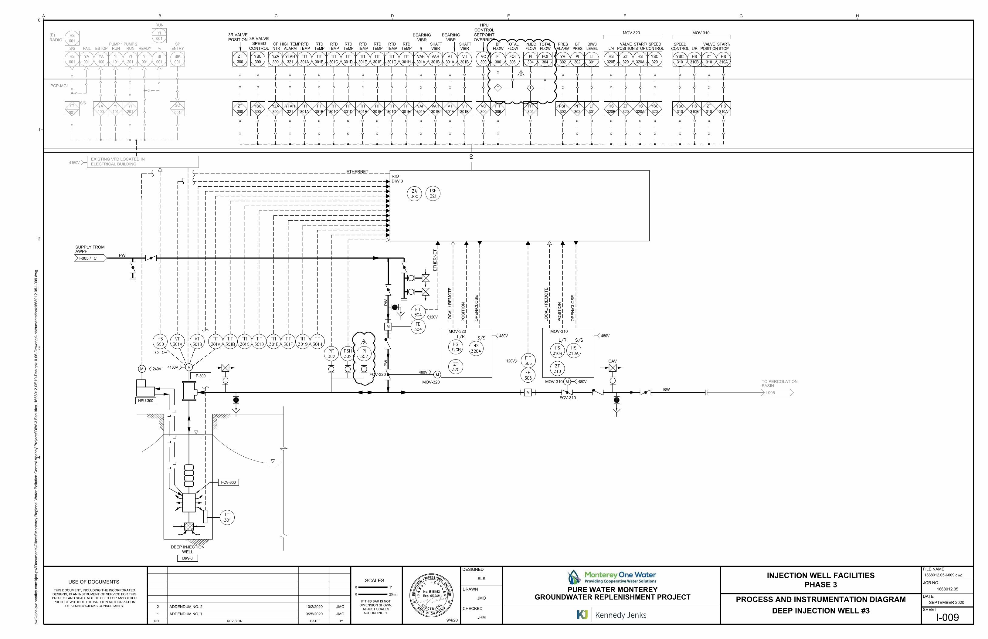
STORMWATER POLLUTION PREVENTION PLAN
for
Pure Water Monterey Groundwater Replenishment Project Injection Well Field, Phase 3
Seaside, California
RISK LEVEL 1
Legally Responsible Person (LRP): Paul Sciuto
General Manager
Monterey One Water
5 Harris Court, Building D, Monterey, CA 93940
Prepared for: Monterey One Water
5 Harris Court, Building D, Monterey, CA 93940
Project Address: Seaside, California
SWPPP Prepared by:
Schaaf and Wheeler Consulting Civil Engineers 3 Quail Run Circle, Suite 101,
Salinas, CA 93907 Caitlin J. Gilmore, PE, QSD
SWPPP Preparation Date
October 1, 2020
Estimated Project Dates:
Start of Construction September 2020 Completion of Construction June 2021

PWM Well Field Phase 3 2 August 2020
PWM Well Field Phase 3 i August 2020
Table of Contents
Table of Contents ........................................................................................................................... i
SWPPP Certification Statement by Qualified SWPPP Developer (QSD) ............................... 1
Discharger or Legally Responsible Person ................................................................................. 2
Amendment Log ............................................................................................................................ 3
Section 1 SWPPP Requirements .............................................................................................. 4
1.1 Introduction ..................................................................................................................... 4
1.2 Permit Registration Documents ...................................................................................... 6
1.3 SWPPP Availability and Implementation ....................................................................... 7
1.4 SWPPP Amendments...................................................................................................... 7
1.5 Retention of Records....................................................................................................... 8
1.6 Required Non-Compliance Reporting ............................................................................ 8
1.7 Annual Report ................................................................................................................. 9
1.8 Changes to Permit Coverage ........................................................................................... 9
1.9 Construction Site Monitoring Program ........................................................................... 9
1.10 Notice of Termination .................................................................................................... 9
1.11 Contractor Activities Location Map ............................................................................ 10
Section 2 Project Information ................................................................................................ 11
2.1 Project and Site Description.......................................................................................... 11
2.1.1 Site Description ......................................................................................................... 11
2.1.2 Existing Conditions ................................................................................................... 11
2.1.3 Existing Drainage...................................................................................................... 11
2.1.4 Geology and Groundwater ........................................................................................ 12
2.1.5 Project Description.................................................................................................... 12
2.1.6 Developed Condition ................................................................................................ 12
2.2 Permits and Governing Documents .............................................................................. 12
2.3 Stormwater Run-On from Offsite Areas ....................................................................... 13
2.4 Findings of the Construction Site Sediment and Receiving Water Risk Determination
13
2.5 Construction Schedule .................................................................................................. 15
2.6 Potential Construction Activity and Pollutant Sources ................................................. 15
2.7 Identification of Non-Stormwater Discharges .............................................................. 16
PWM Well Field Phase 3 ii August 2020
2.8 Required Site Map Information .................................................................................... 17
Section 3 Best Management Practices ................................................................................... 18
3.1 Schedule for BMP Implementation .............................................................................. 18
3.2 Erosion and Sediment Control ...................................................................................... 19
3.2.1 Erosion Control ......................................................................................................... 20
3.2.2 Sediment Controls ..................................................................................................... 22
3.2.3 Tracking Control ....................................................................................................... 25
3.2.4 Wind Erosion Control ............................................................................................... 26
3.3 Non-Stormwater Controls and Waste and Materials Management .............................. 27
3.3.1 Non-Stormwater Controls ......................................................................................... 27
3.3.2 Materials Management and Waste Management ...................................................... 33
3.4 Post construction Stormwater Management Measures ................................................. 42
Section 4 BMP Inspection, Maintenance, and Rain Event Action Plans ........................... 43
4.1 BMP Inspection and Maintenance ................................................................................ 43
4.2 Rain Event Action Plans ............................................................................................... 43
Section 5 Training ................................................................................................................... 44
Section 6 Responsible Parties and Operators ....................................................................... 45
6.1 Responsible Parties ....................................................................................................... 45
6.2 Contractors List ............................................................................................................. 46
Section 7 Construction Site Monitoring Program ................................................................ 48
7.1 Purpose ...................................................................................................................... 48
7.2 Applicability of Permit Requirements ...................................................................... 48
7.3. Weather and Rain Event Tracking ............................................................................ 48
7.3.1 Weather Tracking.................................................................................................. 48
7.3.2 Rain Gauges .......................................................................................................... 49
7.4 Monitoring Locations................................................................................................ 49
7.5 Safety and Monitoring Exemptions .......................................................................... 49
7.6 Visual Monitoring ..................................................................................................... 49
7.6.1 Routine Observations and Inspections .................................................................. 50
7.6.1.1 Routine BMP Inspections ............................................................................. 50
7.6.1.2 Non-Stormwater Discharge Observations .................................................... 50
7.6.2 Rain-Event Triggered Observations and Inspections ........................................... 51
7.6.2.1 Visual Observations Prior to a Forecasted Qualifying Rain Event............... 51
PWM Well Field Phase 3 iii August 2020
7.6.2.2 BMP Inspections During an Extended Storm Event..................................... 51
7.6.2.3 Visual Observations Following a Qualifying Rain Event............................. 51
7.6.3 Visual Monitoring Procedures .............................................................................. 51
7.6.4 Visual Monitoring Follow-Up and Reporting....................................................... 52
7.6.5 Visual Monitoring Locations ................................................................................ 52
7.7 Water Quality Sampling and Analysis ...................................................................... 53
7.7.1 Sampling and Analysis Plan for Non-Visible Pollutants in Stormwater Runoff
Discharges ......................................................................................................................... 53
7.7.1.1 Sampling Schedule........................................................................................ 55
7.7.1.2 Sampling Locations ...................................................................................... 55
7.7.1.3 Monitoring Preparation ................................................................................. 56
7.7.1.4 Analytical Constituents ................................................................................. 57
7.7.1.5 Sample Collection ......................................................................................... 57
7.7.1.6 Sample Analysis............................................................................................ 57
7.7.1.7 Data Evaluation and Reporting ..................................................................... 59
7.7.2 Sampling and Analysis Plan for pH and Turbidity in Stormwater Runoff
Discharges ......................................................................................................................... 59
7.7.3 Sampling and Analysis Plan for pH, Turbidity, and SSC in Receiving Water ..... 59
7.7.4 Sampling and Analysis Plan for Non-Stormwater Discharges ............................. 59
7.7.5 Sampling and Analysis Plan for Other Pollutants Required by the Regional Water
Board 61
7.7.6 Training of Sampling Personnel ........................................................................... 61
7.7.7 Sample Collection and Handling .......................................................................... 61
7.7.7.1 Sample Collection ......................................................................................... 61
7.7.7.2 Sample Handling ........................................................................................... 62
7.7.7.3 Sample Documentation Procedures .............................................................. 63
7.8 Active Treatment System Monitoring ...................................................................... 63
7.9 Bioassessment Monitoring ........................................................................................ 63
7.10 Watershed Monitoring Option .................................................................................. 63
7.11 Quality Assurance and Quality Control .................................................................... 63
7.11.1 Field Logs ......................................................................................................... 64
7.11.2 Clean Sampling Techniques ............................................................................. 64
7.11.3 Chain of Custody .............................................................................................. 64
PWM Well Field Phase 3 iv August 2020
7.11.4 QA/QC Samples................................................................................................ 64
7.11.4.1 Field Duplicates .......................................................................................... 64
7.11.4.2 Equipment Blanks ........................................................................................ 65
7.11.4.3 Field Blanks.................................................................................................. 65
7.11.4.4 Travel Blanks ............................................................................................... 65
7.11.5 Data Verification ............................................................................................... 65
7.12 Records Retention ..................................................................................................... 66
CSMP Attachment 1: Weather Reports................................................................................. 67
CSMP Attachment 2: Monitoring Records ........................................................................... 69
CSMP Attachment 3: Example Forms ................................................................................... 71
CSMP Attachment 4: Field Meter Instructions .................................................................... 81
CSMP Attachment 5: Supplemental Information................................................................. 83
Section 8 References ................................................................................................................ 85
Appendix A: Calculations ...................................................................................................... 86
Appendix B: Site Maps .......................................................................................................... 88
Appendix C: Permit Registration Documents....................................................................... 90
Appendix D: SWPPP Amendments ....................................................................................... 92
Appendix E: Submitted Changes to PRDs ............................................................................ 95
Appendix F: Construction Schedule ..................................................................................... 97
Appendix G: Construction Activities, Materials Used, and Associated Pollutants ............. 99
Appendix H: CASQA Stormwater BMP Handbook Portal: Construction Fact Sheets .... 102
Appendix I: BMP Inspection Form ....................................................................................... 104
Appendix J: Project Specific Rain Event Action Plan Template .......................................... 112
Appendix K: Training Reporting Form .............................................................................. 114
Appendix L: Responsible Parties ........................................................................................ 116
Appendix M: Contractors and Subcontractors .................................................................... 120
Appendix N: Construction General Permit ........................................................................ 121
Appendix O: Retention of Records / Construction Records ............................................... 123
Appendix P: Agency Approvals and Miscellaneous Documents ....................................... 124
Appendix Q: Test Methods, Detection Limits, Reporting Units, Applicable NALs and NELs
125
Appendix R: Erosion Control Plans ................................................................................... 126
Appendix S: Contractor Activities Location Map .............................................................. 127

PWM Well Field Phase 3 v August 2020
PWM Well Field Phase 3 1 August 2020
SWPPP Certification Statement by Qualified SWPPP
Developer (QSD)
Project Name:
Pure Water Monterey Groundwater Replenishment Project,
Injection Well Field (PWM Well Field) Phase 3
Project Number/ID
“This Stormwater Pollution Prevention Plan and Attachments were prepared under my direction to
meet the requirements of the California Construction General Permit (SWRCB Orders No. 2009-009-
DWQ as amended by Order 2010-0014-DWQ and Order 2012-0006-DWQ). I certify that I am a
Qualified SWPPP Developer in good standing as of the date signed below.”
October 5, 2020
QSD Signature
Caitlin Gilmore, PE
Date
22060
QSD Name
Senior Project Manager, Schaaf & Wheeler
QSD Certificate Number
(415) 823-4964
Title and Affiliation
Telephone Number
PWM Well Field 2 May 2017
Discharger or Legally Responsible Person
Approval and Certification of the Stormwater Pollution Prevention Plan
Project Name:
Pure Water Monterey Groundwater Replenishment
Project, Injection Well Field (PWM Well Field) Phase 3
Project Number/ID
“I certify under penalty of law that this document and all Attachments were prepared under my
direction or supervision in accordance with a system designed to assure that qualified personnel
properly gather and evaluate the information submitted. Based on my inquiry of the person or persons
who manage the system or those persons directly responsible for gathering the information, to the best
of my knowledge and belief, the information submitted is, true, accurate, and complete. I am aware
that there are significant penalties for submitting false information, including the possibility of fine
and imprisonment for knowing violations."
Legally Responsible Person [if organization]
Signature of [Authorized Representative of] Legally
Responsible Person or Approved Signatory
Date
Name of [Authorized Representative of] Legally
Responsible Person or Approved Signatory
Telephone Number
PWM Well Field 3 May 2017
Amendment Log
Project Name: Pure Water Monterey Groundwater Replenishment Project, Injection Well Field (PWM Well Field) Phase 3
Project Number/ID [if applicable]
Table 1.1: SWPPP Amendment Log
Amendment
No. Date
Brief Description of Amendment, include
section and page number
Prepared and Approved
By
Name:
QSD#
Name:
QSD#
Name:
QSD#
Name:
QSD#
Name:
QSD#
Name:
QSD#
Name:
QSD#
Name:
QSD#
Name:
QSD#
PWM Well Field Phase 3 4 August 2020
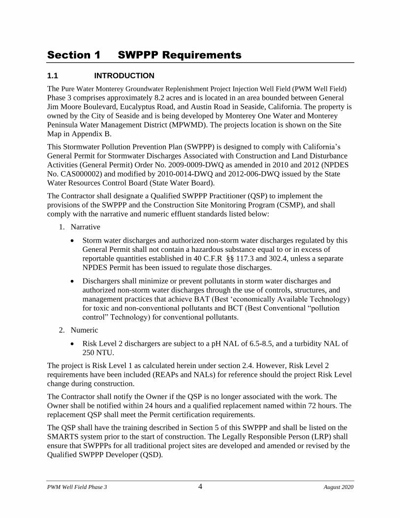
Section 1 SWPPP Requirements
1.1 INTRODUCTION
The Pure Water Monterey Groundwater Replenishment Project Injection Well Field (PWM Well Field)
Phase 3 comprises approximately 8.2 acres and is located in an area bounded between General
Jim Moore Boulevard, Eucalyptus Road, and Austin Road in Seaside, California. The property is
owned by the City of Seaside and is being developed by Monterey One Water and Monterey
Peninsula Water Management District (MPWMD). The projects location is shown on the Site
Map in Appendix B.
This Stormwater Pollution Prevention Plan (SWPPP) is designed to comply with California’s
General Permit for Stormwater Discharges Associated with Construction and Land Disturbance
Activities (General Permit) Order No. 2009-0009-DWQ as amended in 2010 and 2012 (NPDES
No. CAS000002) and modified by 2010-0014-DWQ and 2012-006-DWQ issued by the State
Water Resources Control Board (State Water Board).
The Contractor shall designate a Qualified SWPPP Practitioner (QSP) to implement the
provisions of the SWPPP and the Construction Site Monitoring Program (CSMP), and shall
comply with the narrative and numeric effluent standards listed below:
1. Narrative
• Storm water discharges and authorized non-storm water discharges regulated by this
General Permit shall not contain a hazardous substance equal to or in excess of
reportable quantities established in 40 C.F.R §§ 117.3 and 302.4, unless a separate
NPDES Permit has been issued to regulate those discharges.
• Dischargers shall minimize or prevent pollutants in storm water discharges and
authorized non-storm water discharges through the use of controls, structures, and
management practices that achieve BAT (Best ‘economically Available Technology)
for toxic and non-conventional pollutants and BCT (Best Conventional “pollution
control” Technology) for conventional pollutants.
2. Numeric
• Risk Level 2 dischargers are subject to a pH NAL of 6.5-8.5, and a turbidity NAL of
250 NTU.
The project is Risk Level 1 as calculated herein under section 2.4. However, Risk Level 2
requirements have been included (REAPs and NALs) for reference should the project Risk Level
change during construction.
The Contractor shall notify the Owner if the QSP is no longer associated with the work. The
Owner shall be notified within 24 hours and a qualified replacement named within 72 hours. The
replacement QSP shall meet the Permit certification requirements.
The QSP shall have the training described in Section 5 of this SWPPP and shall be listed on the
SMARTS system prior to the start of construction. The Legally Responsible Person (LRP) shall
ensure that SWPPPs for all traditional project sites are developed and amended or revised by the
Qualified SWPPP Developer (QSD).
PWM Well Field Phase 3 5 August 2020
The QSP is responsible for erosion control on the site and shall supplement the erosion control
plan shown on Construction Document where the facilities shown on the Construction
Documents are not preventing erosion. The QSP shall make corrective measures as soon as
erosion is observed and shall report these measures to the QSD by email within 24 hours.
This SWPPP has been prepared following the SWPPP Template provided on the California
Stormwater Quality Association Stormwater Best Management Practice Handbook Portal:
Construction (CASQA, 2012). In accordance with the General Permit, Section XIV, this
SWPPP is designed to address the following objectives:
• All pollutants and their sources, including sources of sediment associated with
construction, construction site erosion and other activities associated with construction
activity are controlled;
• Where not otherwise required to be under a Regional Water Quality Control Board
(Regional Water Board) permit, all non-stormwater discharges are identified and either
eliminated, controlled, or treated;
• Site BMPs are effective and result in the reduction or elimination of pollutants in
stormwater discharges and authorized non-stormwater discharges from construction
activity to the Best Available Technology/Best Control Technology (BAT/BCT)
standard; Calculations and design details as well as BMP controls for are complete and
correct, (see Appendices A and R); and
• Stabilization BMPs installed to reduce or eliminate pollutants after construction are
completed.
• Identify post-construction BMPs, which are those measures to be installed during
construction that are intended to reduce or eliminate pollutants after construction is
completed. See Section 3.4 for post –construction BMPs.
• Identify and provide methods to implement BMP inspection, visual monitoring, and
Construction Site Monitoring Program (CSMP) requirements to comply with the General
Permit.
Rain Event Action Plan (REAP)
In addition to the narrative and numeric effluent standards listed above, the discharger shall also
have the contractor’s QSP develop and implement a Rain Event Action Plan (REAP), which is
an additional Risk Level 2 requirement. A template of the REAP is included in Appendix J.
1. Additional Risk Level 2 Requirement: The discharger shall ensure a QSP develop a Rain
Event Action Plan (REAP) 48 hours prior to any likely precipitation event. A likely
precipitation event is any weather pattern that is forecast to have a 50% or greater
probability of producing precipitation in the project area. The discharger shall ensure a
QSP obtain a printed copy of precipitation forecast information from the National
Weather Service Forecast Office (e.g., by entering the zip code of the project’s location at
http://www.srh.noaa.gov/forecast).
2. The discharger shall ensure a QSP develop the REAPs for all phases of construction (i.e.,
Grading and Land Development, Streets and Utilities, Vertical Construction, Final
Landscaping and Site Stabilization).
PWM Well Field Phase 3 6 August 2020
3. The discharger shall ensure a QSP ensure that the REAP include, at a minimum, the
following site information:
a. Site Address
b. Calculated Risk Level (2 or 3)
c. Site Storm Water Manager Information including the name, company, and 24-
hour emergency telephone number
d. Erosion and Sediment Control Provider information including the name,
company, and 24-hour emergency telephone number
e. Storm Water Sampling Agent information including the name, company,
and 24-hour emergency telephone number
4. The discharger shall ensure a QSP include in the REAP, at a minimum, the following
project phase information:
a. Activities associated with each construction phase
b. Trades active on the construction site during each construction phase
c. Trade contractor information
d. Suggested actions for each project phase
5. The discharger shall ensure a QSP develop additional REAPs for project sites where
construction activities are indefinitely halted or postponed (Inactive Construction). At a
minimum, Inactive Construction REAPs must include:
a. Site Address
b. Calculated Risk Level (2 or 3)
c. Site Storm Water Manager Information including the name, company, and
24-hour emergency telephone number
d. Erosion and Sediment Control Provider information including the name,
company, and 24-hour emergency telephone number
e. Storm Water Sampling Agent information including the name, company,
and 24-hour emergency telephone number
f. Trades active on site during Inactive Construction
g. Trade contractor information
h. Suggested actions for inactive construction sites
6. The discharger shall ensure a QSP begin implementation and make the REAP available
onsite no later than 24 hours prior to the likely precipitation event.
7. The discharger shall ensure a QSP maintain onsite a paper copy of each REAP onsite in
compliance with the record retention requirements of the Special Provisions in this
General Permit.
1.2 PERMIT REGISTRATION DOCUMENTS
Required Permit Registration Documents (PRDs) shall be submitted to the State Water Board via
the Stormwater Multi Application and Report Tracking System (SMARTS) by the Legally
Responsible Person (LRP), or authorized personnel (i.e., Approved Signatory) under the
direction of the LRP. Failure to obtain coverage under this General Permit for storm water
discharges to waters of the United States is a violation of the Clean Water Act and the California
Water Code. The project-specific PRDs include:
1. Notice of Intent (NOI);
PWM Well Field Phase 3 7 August 2020
2. Risk Assessment (Construction Site Sediment and Receiving Water Risk Determination);
3. Site Map;
4. Annual Fee;
5. Signed Certification Statement (LRP Certification is provided electronically with
SMARTS PRD submittal); and
6. SWPPP.
Site Maps can be found in Appendix B. A copy of the submitted PRDs shall also be kept in
Appendix C along with the Waste Discharge Identification (WDID) confirmation.
1.3 SWPPP AVAILABILITY AND IMPLEMENTATION
The QSP shall make the SWPPP available at the construction site during working hours (see
Section 7.5 of CSMP for working hours) while construction is occurring and shall be made
available upon request by a State or Municipal inspector. When the original SWPPP is retained
by a crewmember in a construction vehicle and is not currently at the construction site, current
copies of the BMPs and map/drawing will be left with the field crew and the original SWPPP
shall be made available via a request by radio/telephone. (CGP Section XIV.C)
The SWPPP shall be implemented concurrently with the start of ground disturbing activities and
remain in effect until a Notice of Termination for the site is approved by the Regional Water
Quality Control Board.
1.4 SWPPP AMENDMENTS
The SWPPP should be revised when:
• If there is a General Permit violation.
• When there is a reduction or increase in total disturbed acreage (General Permit Section
II Part C).
• BMPs do not meet the objectives of reducing or eliminating pollutants in stormwater
discharges.
Additionally, the SWPPP shall be amended when:
• There is a change in construction or operations which may affect the discharge of
pollutants to surface waters, groundwater(s), or a municipal separate storm sewer system
(MS4);
• When there is a change in the project duration that changes the project’s risk level; or
• When deemed necessary by the QSD. All changes shall be made by the QSD as formal
amendments to the SWPPP.
The following items shall be included in each amendment:
• Who requested the amendment;
• The location of proposed change;
• The reason for change;
PWM Well Field Phase 3 8 August 2020
• The original BMP proposed, if any; and
• The new BMP proposed.
Amendment shall be logged at the front of the SWPPP and certification kept in Appendix D.
The SWPPP text shall be revised, replaced, and/or hand annotated as necessary to properly
convey the amendment. SWPPP amendments must be made by a QSD.
1.5 RETENTION OF RECORDS
The QSP is required to maintain a paper or electronic copy of all required records throughout
construction, and provide copies of these reports to the LRP when requested during the job and
at the end of the job. The LRP shall retain a copy of all required records for three years from the
date generated or the date submitted to the State Water Board or Regional Water Boards,
whichever is the latter. A copy of these records shall be maintained at the Site and within
Appendix O of this SWPPP until construction is complete. Records assisting in the determination
of compliance with the General Permit shall be made available within a reasonable time, to the
Regional Water Board, State Water Board or U.S. Environmental Protection Agency (EPA) upon
request. Requests by the Regional Water Board for retention of records for a period longer than
three years shall be adhered to.
1.6 REQUIRED NON-COMPLIANCE REPORTING
If a General Permit discharge violation occurs the QSP shall immediately notify the LRP. The
LRP shall include information on the violation with the Annual Report. Corrective measures
will be implemented immediately following identification of the discharge or written notice of
non-compliance from the Regional Water Board. Discharges and corrective actions must be
documented and include the following items:
• The date, time, location, nature of operation and type of unauthorized discharge.
• The cause or nature of the notice or order.
• The control measures (BMPs) deployed before the discharge event, or prior to receiving
notice or order.
• The date of deployment and type of control measures (BMPs) deployed after the
discharge event, or after receiving the notice or order, including additional measures
installed or planned to reduce or prevent re-occurrence.
Reporting requirements for Numeric Action Levels (NALs) exceedances are discussed in Section
7.7.2.7.
PWM Well Field Phase 3 9 August 2020
1.7 ANNUAL REPORT
The QSP is responsible for preparing certifying, and electronically submitting an Annual Report
no later than September 1st of each year. Reporting requirements are identified in Section XVI
of the General Permit and include (but are not limited to) providing a summary of :
1) Sampling and analysis results including laboratory reports, analytical methods and
reporting limits and chain of custody forms (if applicable to this Risk Level 1 site);
2) Corrective actions and compliance activities, including those not implemented;
3) Violations of the General Permit;
4) Date, time, place, and name(s) of the inspector(s) for all sampling, inspections, and field
measurement activities;
5) Visual observation and sample collection exception records; and
6) Training documentation of all personnel responsible for General Permit compliance
activities.
The LRP is responsible for certifying the Annual Report via SMARTS, and is required to retain
paper copies of all submitted documents for a period of 3 years after the Notice of Termination is
accepted.
1.8 CHANGES TO PERMIT COVERAGE
The Construction General Permit allow a permittee to reduce or increase the total acreage
covered under the General Permit when: a portion of the project is complete and/or conditions
for termination of coverage have been met; when ownership of a portion of the project is
purchased by a different entity; or when new acreage is added to the project.
Modified PRDs shall be filed electronically within 30 days of a reduction or increase in total
disturbed area if a change in permit covered acreage is to be sought. The SWPPP shall be
modified appropriately, shall be logged at the front of the SWPPP and cetrification of SWPPP
amendments are to be kept in Appendix D. Updated PRDs submitted electronically via SMARTS
can be found in Appendix E.
1.9 CONSTRUCTION SITE MONITORING PROGRAM
The QSP is to implement the Construction Site Monitoring Program (CSMP) in accordance with
the requirements found in Appendix N. The CSMP is included in this SWPPP in Section 7.
1.10 NOTICE OF TERMINATION
A Notice of Termination (NOT) must be submitted electronically by the LRP via SMARTS to
terminate coverage under the General Permit. The NOT must include a final Site Map and
representative photographs of the project site that demonstrate final stabilization has been
achieved. The NOT shall be submitted within 90 days of completion of construction. The
Regional Water Board will consider a construction site complete when the conditions of the
General Permit, Section II.D have been met and final stabilization in the form of the following is
achieved:
PWM Well Field Phase 3 10 August 2020
• The site will not pose any additional sediment discharge risk than it did prior to
construction activity.
• All construction related equipment, materials and any temporary BMPs no longer needed
are removed from the site.
• Post-construction storm water management measures are installed, and a long-term
maintenance plan that is designed for a minimum of five years has been developed.
The NOT must demonstrate through photos that the project meets all of the requirements of
Section II.D.1 of the General Permit by the 70% final cover method (no computational proof
required).
1.11 CONTRACTOR ACTIVITIES LOCATION MAP
Locations of storage areas for waste, vehicles, service, loading/unloading of materials, access
(entrance/exits) points to construction site, fueling, and water storage, water transfer for dust
control and compaction practices shall be shown on this map and updated regularly by the QSP.
All updates of the Contractor Activities Location Map shall be included in Appendix S.
PWM Well Field Phase 3 11 August 2020
Section 2 Project Information
2.1 PROJECT AND SITE DESCRIPTION
2.1.1 Site Description
The PWM Well Field site comprises approximately 8.2 acres and is located at an area bounded
by General Jim Moore Boulevard to the west, Eucalyptus Road to the north, and Austin
Road/Bureau of Land Management lands to the south and east, in Seaside, California. Phase 3 is
the development of the final two sites (Well Sites 1 and 4), which total 1.6 acres. The remaining
6.6 acres were developed during Phases 1 and 2 of the project. The property is owned by the
City of Seaside and is being developed by the Monterey One Water (M1W) and Monterey
Peninsula Water Management District (MPWMD). The project site is located approximately 2.3
miles east of the city of Sand City, and US Highway 1. The project site is located approximately
2.6 miles east of the Monterey Bay. The project is located at 36° 37' 09.62" N
121° 48' 40.39" W and is identified on the Site Map in Appendix B.
2.1.2 Existing Conditions
As of the initial date of this SWPPP, the project site is an area of dune sands with a history of
military activities due to the site formerly being used for defense purposes (former Fort Ord
lands). The project site was previously used by the United States Army for Munitions training
operations conducted at the former Fort Ord. Historic sources of contamination include remnants
of army Munitions and Explosives of Concern (MEC). Environmental cleanup activities were
conducted at this site under the Environmental Services Cooperative Agreement (ESCA)
between the Fort Ord Reuse Authority and the U.S. Army. Once these activities were completed,
the land was conveyed to the City of Seaside (City).
Phases 1 and 2 of the Project developed well sites 2 and 3 and a centrally located electrical
switchgear yard, and installed pipelines and conduits connecting these sites to existing utilities in
General Jim Moore Blvd. The Phase 2 project also deepened the existing percolation pond to
add capacity for use during backflushing of the wells.
2.1.3 Existing Drainage
The project site is gently sloped to the southwest. The elevation of the project site ranges from
300 to 450 feet above mean sea level (msl), with a 4% to 5% slope along the existing unpaved
road. Surface drainage at the site currently is limited and storm water percolates into the native
sandy soil (Dune Sands) of the area. Stormwater discharges, from the site, are not considered
direct discharges, as defined by the State Water Board into Monterey Bay. Existing site
topography, drainage patterns, and stormwater conveyance systems are shown on the Site Plan in
Appendix B.
Stormwater from the area percolates into the Salinas Valley Groundwater Basin, Seaside Sub-
Basin. The aquifer is not listed for any water quality impairment.
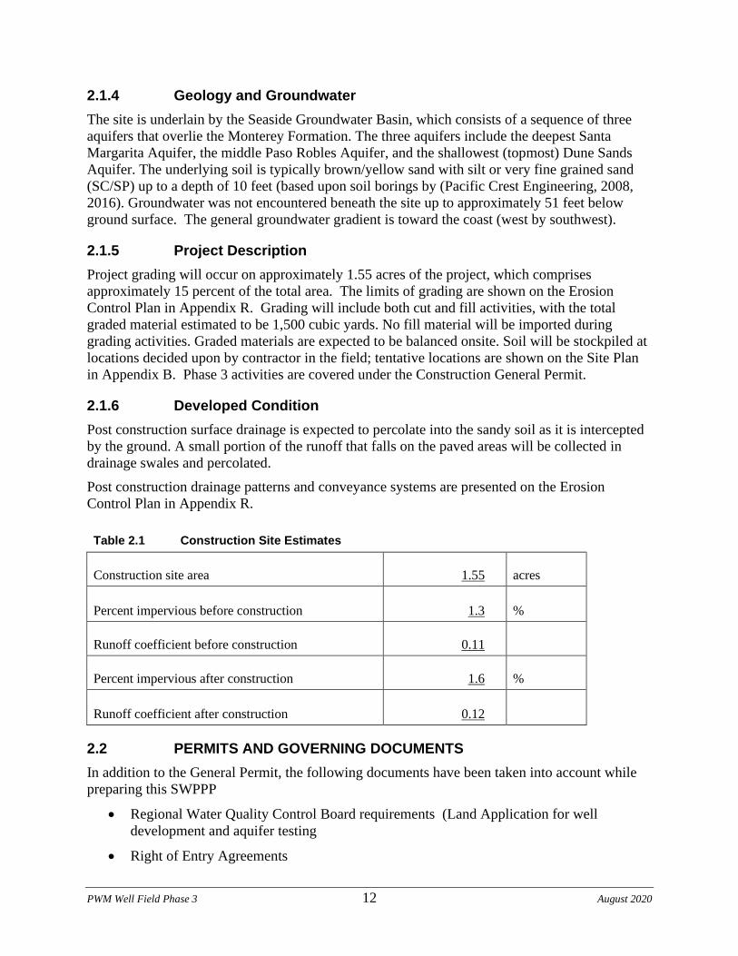
PWM Well Field Phase 3 12 August 2020
2.1.4 Geology and Groundwater
The site is underlain by the Seaside Groundwater Basin, which consists of a sequence of three
aquifers that overlie the Monterey Formation. The three aquifers include the deepest Santa
Margarita Aquifer, the middle Paso Robles Aquifer, and the shallowest (topmost) Dune Sands
Aquifer. The underlying soil is typically brown/yellow sand with silt or very fine grained sand
(SC/SP) up to a depth of 10 feet (based upon soil borings by (Pacific Crest Engineering, 2008,
2016). Groundwater was not encountered beneath the site up to approximately 51 feet below
ground surface. The general groundwater gradient is toward the coast (west by southwest).
2.1.5 Project Description
Project grading will occur on approximately 1.55 acres of the project, which comprises
approximately 15 percent of the total area. The limits of grading are shown on the Erosion
Control Plan in Appendix R. Grading will include both cut and fill activities, with the total
graded material estimated to be 1,500 cubic yards. No fill material will be imported during
grading activities. Graded materials are expected to be balanced onsite. Soil will be stockpiled at
locations decided upon by contractor in the field; tentative locations are shown on the Site Plan
in Appendix B. Phase 3 activities are covered under the Construction General Permit.
2.1.6 Developed Condition
Post construction surface drainage is expected to percolate into the sandy soil as it is intercepted
by the ground. A small portion of the runoff that falls on the paved areas will be collected in
drainage swales and percolated.
Post construction drainage patterns and conveyance systems are presented on the Erosion
Control Plan in Appendix R.
Table 2.1 Construction Site Estimates
Construction site area 1.55 acres
Percent impervious before construction 1.3 %
Runoff coefficient before construction 0.11
Percent impervious after construction 1.6 %
Runoff coefficient after construction 0.12
2.2 PERMITS AND GOVERNING DOCUMENTS
In addition to the General Permit, the following documents have been taken into account while
preparing this SWPPP
• Regional Water Quality Control Board requirements (Land Application for well
development and aquifer testing
• Right of Entry Agreements
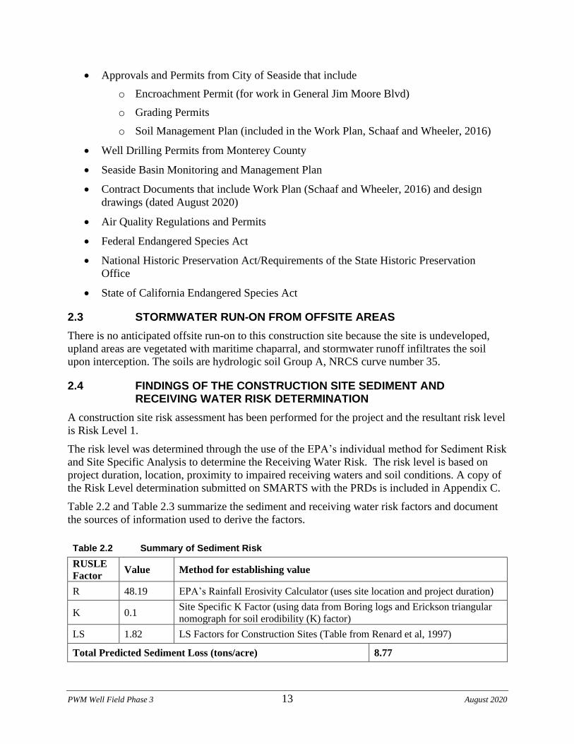
PWM Well Field Phase 3 13 August 2020
• Approvals and Permits from City of Seaside that include
o Encroachment Permit (for work in General Jim Moore Blvd)
o Grading Permits
o Soil Management Plan (included in the Work Plan, Schaaf and Wheeler, 2016)
• Well Drilling Permits from Monterey County
• Seaside Basin Monitoring and Management Plan
• Contract Documents that include Work Plan (Schaaf and Wheeler, 2016) and design
drawings (dated August 2020)
• Air Quality Regulations and Permits
• Federal Endangered Species Act
• National Historic Preservation Act/Requirements of the State Historic Preservation
Office
• State of California Endangered Species Act
2.3 STORMWATER RUN-ON FROM OFFSITE AREAS
There is no anticipated offsite run-on to this construction site because the site is undeveloped,
upland areas are vegetated with maritime chaparral, and stormwater runoff infiltrates the soil
upon interception. The soils are hydrologic soil Group A, NRCS curve number 35.
2.4 FINDINGS OF THE CONSTRUCTION SITE SEDIMENT AND RECEIVING WATER RISK DETERMINATION
A construction site risk assessment has been performed for the project and the resultant risk level
is Risk Level 1.
The risk level was determined through the use of the EPA’s individual method for Sediment Risk
and Site Specific Analysis to determine the Receiving Water Risk. The risk level is based on
project duration, location, proximity to impaired receiving waters and soil conditions. A copy of
the Risk Level determination submitted on SMARTS with the PRDs is included in Appendix C.
Table 2.2 and Table 2.3 summarize the sediment and receiving water risk factors and document
the sources of information used to derive the factors.
Table 2.2 Summary of Sediment Risk
RUSLE
Factor Value Method for establishing value
R 48.19 EPA’s Rainfall Erosivity Calculator (uses site location and project duration)
K 0.1 Site Specific K Factor (using data from Boring logs and Erickson triangular
nomograph for soil erodibility (K) factor)
LS 1.82 LS Factors for Construction Sites (Table from Renard et al, 1997)
Total Predicted Sediment Loss (tons/acre) 8.77
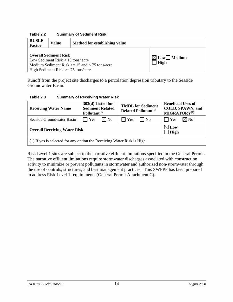
PWM Well Field Phase 3 14 August 2020
Table 2.2 Summary of Sediment Risk
RUSLE
Factor Value Method for establishing value
Overall Sediment Risk
Low Sediment Risk < 15 tons/ acre
Medium Sediment Risk >= 15 and < 75 tons/acre
High Sediment Risk >= 75 tons/acre
Low Medium
High
Runoff from the project site discharges to a percolation depression tributary to the Seaside
Groundwater Basin.
Table 2.3 Summary of Receiving Water Risk
Receiving Water Name
303(d) Listed for
Sediment Related
Pollutant(1)
TMDL for Sediment
Related Pollutant(1)
Beneficial Uses of
COLD, SPAWN, and
MIGRATORY(1)
Seaside Groundwater Basin Yes No Yes No Yes No
Overall Receiving Water Risk Low
High
(1) If yes is selected for any option the Receiving Water Risk is High
Risk Level 1 sites are subject to the narrative effluent limitations specified in the General Permit.
The narrative effluent limitations require stormwater discharges associated with construction
activity to minimize or prevent pollutants in stormwater and authorized non-stormwater through
the use of controls, structures, and best management practices. This SWPPP has been prepared
to address Risk Level 1 requirements (General Permit Attachment C).

PWM Well Field Phase 3 15 August 2020
2.5 CONSTRUCTION SCHEDULE
The site sediment risk was determined based on construction taking place between September 1,
2020 to June 1, 2021. Modification or extension of the schedule (start and end dates) may affect
risk determination and permit requirements. The LRP shall contact the QSD if the schedule
changes during construction to address potential impact to the SWPPP. The estimated schedule
for planned work can be found in Appendix F.
Listed below are the identified phases of construction and their proposed start dates:
September 1, 2020 – February 28, 2021 Site grading, well drilling and development
January 1, 2021 – March 31, 2021 Site grading, trenching and utility installation
February 1, 2021 – May 31 Surface Improvement Construction/Testing
June 1, 2021 – June 30, 2021 Site cleanup and closeout
2.6 POTENTIAL CONSTRUCTION ACTIVITY AND POLLUTANT SOURCES
The following is a list of example construction materials and activities that have the potential to
contribute pollutants, other than sediment, to storm water run-off:
• Vehicle fluids, including oil, grease, petroleum, and coolants
• Asphaltic emulsions associated with asphalt concrete paving operations
• Cement materials associated with Portland cement concrete (PCC) paving operations,
trench installation and utility installation
• Base and subbase material
• Joint and curing compounds
• Concrete curing compounds
• Paints
• Solvents, thinners, and acids
• Raw landscaping materials and wastes (topsoil, plant materials, herbicides, fertilizers,
mulch, pesticides)
• BMP materials (sandbags)
• Treated lumber (materials and waste)
• PCC rubble
• General litter
Construction activities that have the potential to contribute sediment to storm water discharges
include:
• Clearing and grubbing operations
• Grading operations
• Utility excavation operations
• Well drilling and development operations
• Landscaping operations
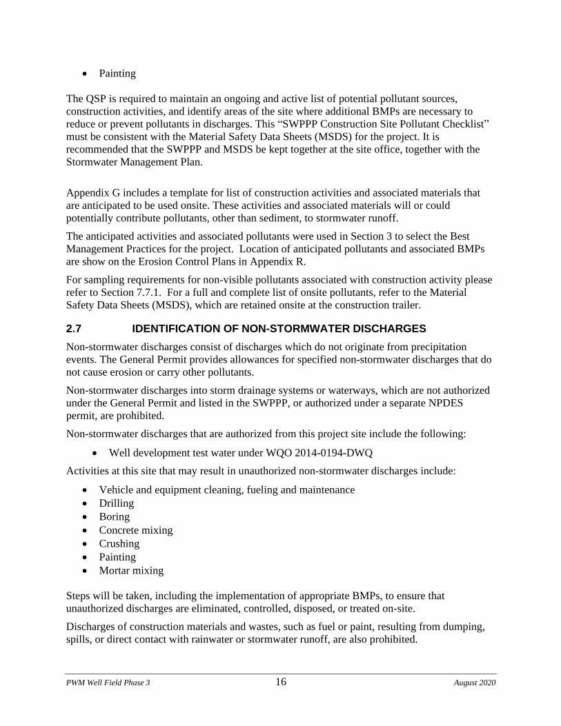
PWM Well Field Phase 3 16 August 2020
• Painting
The QSP is required to maintain an ongoing and active list of potential pollutant sources,
construction activities, and identify areas of the site where additional BMPs are necessary to
reduce or prevent pollutants in discharges. This “SWPPP Construction Site Pollutant Checklist”
must be consistent with the Material Safety Data Sheets (MSDS) for the project. It is
recommended that the SWPPP and MSDS be kept together at the site office, together with the
Stormwater Management Plan.
Appendix G includes a template for list of construction activities and associated materials that
are anticipated to be used onsite. These activities and associated materials will or could
potentially contribute pollutants, other than sediment, to stormwater runoff.
The anticipated activities and associated pollutants were used in Section 3 to select the Best
Management Practices for the project. Location of anticipated pollutants and associated BMPs
are show on the Erosion Control Plans in Appendix R.
For sampling requirements for non-visible pollutants associated with construction activity please
refer to Section 7.7.1. For a full and complete list of onsite pollutants, refer to the Material
Safety Data Sheets (MSDS), which are retained onsite at the construction trailer.
2.7 IDENTIFICATION OF NON-STORMWATER DISCHARGES
Non-stormwater discharges consist of discharges which do not originate from precipitation
events. The General Permit provides allowances for specified non-stormwater discharges that do
not cause erosion or carry other pollutants.
Non-stormwater discharges into storm drainage systems or waterways, which are not authorized
under the General Permit and listed in the SWPPP, or authorized under a separate NPDES
permit, are prohibited.
Non-stormwater discharges that are authorized from this project site include the following:
• Well development test water under WQO 2014-0194-DWQ
Activities at this site that may result in unauthorized non-stormwater discharges include:
• Vehicle and equipment cleaning, fueling and maintenance
• Drilling
• Boring
• Concrete mixing
• Crushing
• Painting
• Mortar mixing
Steps will be taken, including the implementation of appropriate BMPs, to ensure that
unauthorized discharges are eliminated, controlled, disposed, or treated on-site.
Discharges of construction materials and wastes, such as fuel or paint, resulting from dumping,
spills, or direct contact with rainwater or stormwater runoff, are also prohibited.
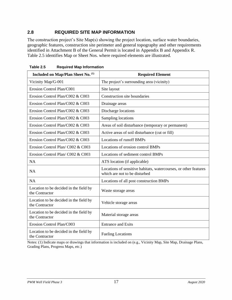
PWM Well Field Phase 3 17 August 2020
2.8 REQUIRED SITE MAP INFORMATION
The construction project’s Site Map(s) showing the project location, surface water boundaries,
geographic features, construction site perimeter and general topography and other requirements
identified in Attachment B of the General Permit is located in Appendix B and Appendix R.
Table 2.5 identifies Map or Sheet Nos. where required elements are illustrated.
Table 2.5 Required Map Information
Included on Map/Plan Sheet No. (1) Required Element
Vicinity Map/G-001 The project’s surrounding area (vicinity)
Erosion Control Plan/C001 Site layout
Erosion Control Plan/C002 & C003 Construction site boundaries
Erosion Control Plan/C002 & C003 Drainage areas
Erosion Control Plan/C002 & C003 Discharge locations
Erosion Control Plan/C002 & C003 Sampling locations
Erosion Control Plan/C002 & C003 Areas of soil disturbance (temporary or permanent)
Erosion Control Plan/C002 & C003 Active areas of soil disturbance (cut or fill)
Erosion Control Plan/C002 & C003 Locations of runoff BMPs
Erosion Control Plan/ C002 & C003 Locations of erosion control BMPs
Erosion Control Plan/ C002 & C003 Locations of sediment control BMPs
NA ATS location (if applicable)
NA Locations of sensitive habitats, watercourses, or other features
which are not to be disturbed
NA Locations of all post construction BMPs
Location to be decided in the field by
the Contractor Waste storage areas
Location to be decided in the field by
the Contractor Vehicle storage areas
Location to be decided in the field by
the Contractor Material storage areas
Erosion Control Plan/C003 Entrance and Exits
Location to be decided in the field by
the Contractor Fueling Locations
Notes: (1) Indicate maps or drawings that information is included on (e.g., Vicinity Map, Site Map, Drainage Plans,
Grading Plans, Progress Maps, etc.)
PWM Well Field Phase 3 18 August 2020
Section 3 Best Management Practices
3.1 SCHEDULE FOR BMP IMPLEMENTATION
The QSP is required to install BMPs as shown on the Erosion Control Plans included in
Appendix R and implement/install the BMPs listed in this section of the SWPPP. The Contractor
shall modify the Erosion Control Plan to reflect the phase of construction and the weather
conditions.
The Contractor shall install BMPs before the site is disturbed (e.g., to provide protection during
grading operations or to reduce or minimize pollution from historic areas of contamination
during construction). The erosion control plan shall be implemented year round.
A BMP Consideration Checklist has been provided in Appendix H, followed by the Fact Sheets
for the BMPs that are recommended for this project, which are included in the following
sections. BMPs will be installed in a sequence to follow the progress of demolition and
construction. As each area of the site is disturbed, BMPs will be installed to conform to the
specific site requirements. In general, the project will have limited areas exposed at any time.
Where practical, construction will occur during dry periods. The site BMP implementation
schedule is shown in Table 3.1, and described in the subsequent sections.
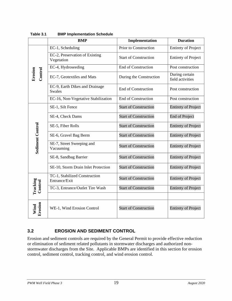
PWM Well Field Phase 3 19 August 2020
Table 3.1 BMP Implementation Schedule
BMP Implementation Duration
Ero
sio
n
Co
ntr
ol
EC-1, Scheduling Prior to Construction Entirety of Project
EC-2, Preservation of Existing
Vegetation Start of Construction Entirety of Project
EC-4, Hydroseeding End of Construction Post construction
EC-7, Geotextiles and Mats During the Construction During certain
field activities
EC-9, Earth Dikes and Drainage
Swales End of Construction Post construction
EC-16, Non-Vegetative Stabilization End of Construction Post construction
Sed
imen
t C
on
trol
SE-1, Silt Fence Start of Construction Entirety of Project
SE-4, Check Dams Start of Construction End of Project
SE-5, Fiber Rolls Start of Construction Entirety of Project
SE-6, Gravel Bag Berm Start of Construction Entirety of Project
SE-7, Street Sweeping and
Vacuuming Start of Construction Entirety of Project
SE-8, Sandbag Barrier Start of Construction Entirety of Project
SE-10, Storm Drain Inlet Protection Start of Construction Entirety of Project
Tra
ckin
g
Con
trol
TC-1, Stabilized Construction
Entrance/Exit Start of Construction Entirety of Project
TC-3, Entrance/Outlet Tire Wash Start of Construction Entirety of Project
Win
d
Ero
sio
n
WE-1, Wind Erosion Control Start of Construction Entirety of Project
3.2 EROSION AND SEDIMENT CONTROL
Erosion and sediment controls are required by the General Permit to provide effective reduction
or elimination of sediment related pollutants in stormwater discharges and authorized non-
stormwater discharges from the Site. Applicable BMPs are identified in this section for erosion
control, sediment control, tracking control, and wind erosion control.
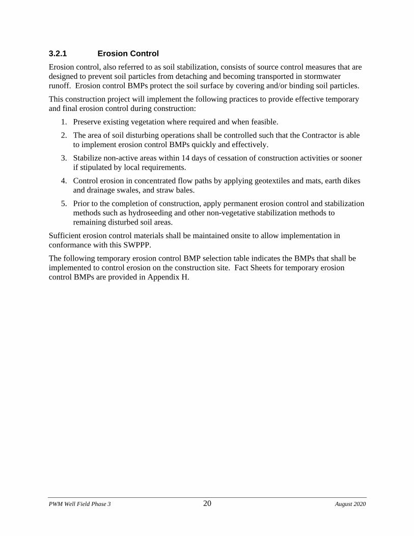
PWM Well Field Phase 3 20 August 2020
3.2.1 Erosion Control
Erosion control, also referred to as soil stabilization, consists of source control measures that are
designed to prevent soil particles from detaching and becoming transported in stormwater
runoff. Erosion control BMPs protect the soil surface by covering and/or binding soil particles.
This construction project will implement the following practices to provide effective temporary
and final erosion control during construction:
1. Preserve existing vegetation where required and when feasible.
2. The area of soil disturbing operations shall be controlled such that the Contractor is able
to implement erosion control BMPs quickly and effectively.
3. Stabilize non-active areas within 14 days of cessation of construction activities or sooner
if stipulated by local requirements.
4. Control erosion in concentrated flow paths by applying geotextiles and mats, earth dikes
and drainage swales, and straw bales.
5. Prior to the completion of construction, apply permanent erosion control and stabilization
methods such as hydroseeding and other non-vegetative stabilization methods to
remaining disturbed soil areas.
Sufficient erosion control materials shall be maintained onsite to allow implementation in
conformance with this SWPPP.
The following temporary erosion control BMP selection table indicates the BMPs that shall be
implemented to control erosion on the construction site. Fact Sheets for temporary erosion
control BMPs are provided in Appendix H.
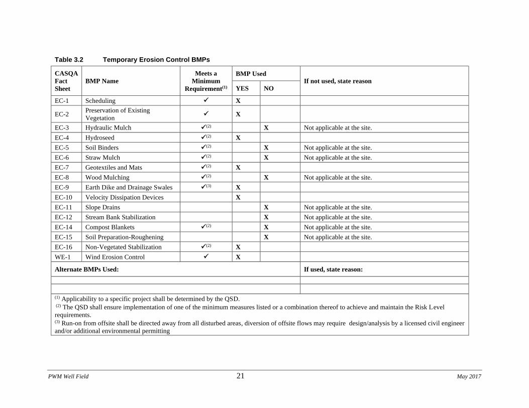
PWM Well Field 21 May 2017
Table 3.2 Temporary Erosion Control BMPs
CASQA
Fact
Sheet
BMP Name
Meets a
Minimum
Requirement(1)
BMP Used If not used, state reason
YES NO
EC-1 Scheduling ✓ X
EC-2 Preservation of Existing
Vegetation ✓ X
EC-3 Hydraulic Mulch ✓(2) X Not applicable at the site.
EC-4 Hydroseed ✓(2) X
EC-5 Soil Binders ✓(2) X Not applicable at the site.
EC-6 Straw Mulch ✓(2) X Not applicable at the site.
EC-7 Geotextiles and Mats ✓(2) X
EC-8 Wood Mulching ✓(2) X Not applicable at the site.
EC-9 Earth Dike and Drainage Swales ✓(3) X
EC-10 Velocity Dissipation Devices X
EC-11 Slope Drains X Not applicable at the site.
EC-12 Stream Bank Stabilization X Not applicable at the site.
EC-14 Compost Blankets ✓(2) X Not applicable at the site.
EC-15 Soil Preparation-Roughening X Not applicable at the site.
EC-16 Non-Vegetated Stabilization ✓(2) X
WE-1 Wind Erosion Control ✓ X
Alternate BMPs Used: If used, state reason:
(1) Applicability to a specific project shall be determined by the QSD. (2) The QSD shall ensure implementation of one of the minimum measures listed or a combination thereof to achieve and maintain the Risk Level
requirements. (3) Run-on from offsite shall be directed away from all disturbed areas, diversion of offsite flows may require design/analysis by a licensed civil engineer
and/or additional environmental permitting
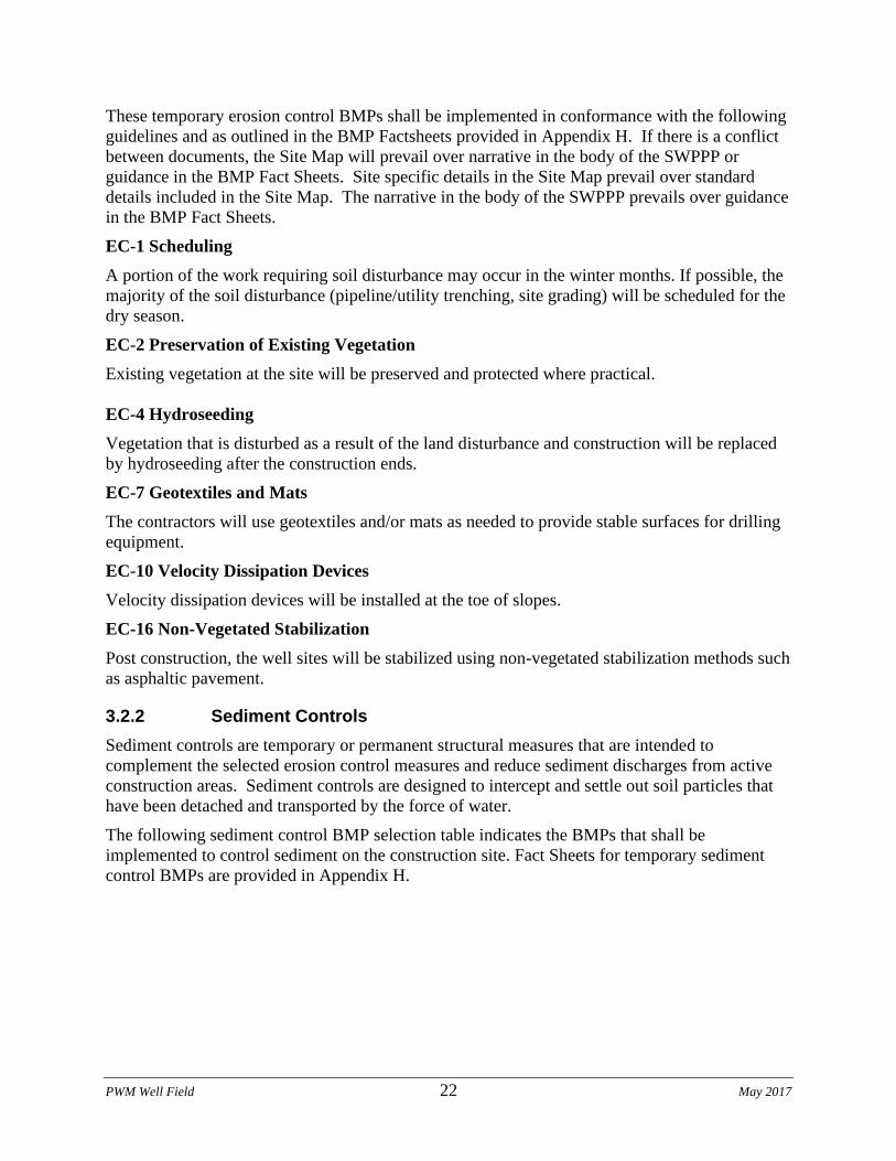
PWM Well Field 22 May 2017
These temporary erosion control BMPs shall be implemented in conformance with the following
guidelines and as outlined in the BMP Factsheets provided in Appendix H. If there is a conflict
between documents, the Site Map will prevail over narrative in the body of the SWPPP or
guidance in the BMP Fact Sheets. Site specific details in the Site Map prevail over standard
details included in the Site Map. The narrative in the body of the SWPPP prevails over guidance
in the BMP Fact Sheets.
EC-1 Scheduling
A portion of the work requiring soil disturbance may occur in the winter months. If possible, the
majority of the soil disturbance (pipeline/utility trenching, site grading) will be scheduled for the
dry season.
EC-2 Preservation of Existing Vegetation
Existing vegetation at the site will be preserved and protected where practical.
EC-4 Hydroseeding
Vegetation that is disturbed as a result of the land disturbance and construction will be replaced
by hydroseeding after the construction ends.
EC-7 Geotextiles and Mats
The contractors will use geotextiles and/or mats as needed to provide stable surfaces for drilling
equipment.
EC-10 Velocity Dissipation Devices
Velocity dissipation devices will be installed at the toe of slopes.
EC-16 Non-Vegetated Stabilization
Post construction, the well sites will be stabilized using non-vegetated stabilization methods such
as asphaltic pavement.
3.2.2 Sediment Controls
Sediment controls are temporary or permanent structural measures that are intended to
complement the selected erosion control measures and reduce sediment discharges from active
construction areas. Sediment controls are designed to intercept and settle out soil particles that
have been detached and transported by the force of water.
The following sediment control BMP selection table indicates the BMPs that shall be
implemented to control sediment on the construction site. Fact Sheets for temporary sediment
control BMPs are provided in Appendix H.
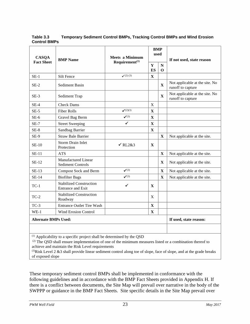
PWM Well Field 23 May 2017
Table 3.3 Temporary Sediment Control BMPs, Tracking Control BMPs and Wind Erosion Control BMPs
CASQA
Fact Sheet BMP Name
Meets a Minimum
Requirement(1)
BMP
used
If not used, state reason
Y
ES
N
O
SE-1 Silt Fence ✓(2) (3) X
SE-2 Sediment Basin X Not applicable at the site. No
runoff to capture
SE-3 Sediment Trap X Not applicable at the site. No
runoff to capture
SE-4 Check Dams X
SE-5 Fiber Rolls ✓(2)(3) X
SE-6 Gravel Bag Berm ✓(3) X
SE-7 Street Sweeping ✓ X
SE-8 Sandbag Barrier X
SE-9 Straw Bale Barrier X Not applicable at the site.
SE-10 Storm Drain Inlet
Protection ✓ RL2&3 X
SE-11 ATS X Not applicable at the site.
SE-12 Manufactured Linear
Sediment Controls X Not applicable at the site.
SE-13 Compost Sock and Berm ✓(3) X Not applicable at the site.
SE-14 Biofilter Bags ✓(3) X Not applicable at the site.
TC-1 Stabilized Construction
Entrance and Exit ✓ X
TC-2 Stabilized Construction
Roadway X
TC-3 Entrance Outlet Tire Wash X
WE-1 Wind Erosion Control X
Alternate BMPs Used: If used, state reason:
(1) Applicability to a specific project shall be determined by the QSD (2) The QSD shall ensure implementation of one of the minimum measures listed or a combination thereof to
achieve and maintain the Risk Level requirements (3)Risk Level 2 &3 shall provide linear sediment control along toe of slope, face of slope, and at the grade breaks
of exposed slope
These temporary sediment control BMPs shall be implemented in conformance with the
following guidelines and in accordance with the BMP Fact Sheets provided in Appendix H. If
there is a conflict between documents, the Site Map will prevail over narrative in the body of the
SWPPP or guidance in the BMP Fact Sheets. Site specific details in the Site Map prevail over
PWM Well Field 24 May 2017
standard details included in the Site Map. The narrative in the body of the SWPPP prevails over
guidance in the BMP Fact Sheets.
SE-1 Silt Fence
Refer to the plans for silt fence installation and maintenance. In general, silt fence shall be
installed around the perimeter of any disturbed area on the Project site. Silt fence shall be
installed at the perimeter of the project and around any temporary spoil areas and material
stockpiles.
A silt fence is a temporary sediment barrier consisting of woven geotextile stretched across and
attached to supporting posts, trenched-in and, depending upon the strength of fabric used,
supported with plastic or wire mesh fence. Silt fences trap sediment by intercepting and
detaining small amounts of sediment-laden runoff from disturbed areas in order to promote
sedimentation behind the fence. Silt fences are proposed on top of slopes to reduce the potential
for wind to carry sediment from disturbed soils. Silt fences shall remain in place until the
disturbed area is permanently stabilized, after which, the silt fence shall be removed and properly
disposed of.
SE-4 Check Dams
Refer to the plans for check dam placement placement. In general straw bale check dams shall be
installed in unlined roadside ditches where velocities may result in sediment transport. around
the perimeter of any disturbed area on the Project site.
A check dam shall consist of one or more rice straw bales staked in place using wooden stakes,
slowing the flow of water in the roadside ditch and acting as a filter to catch sediment.
SE-5 Fiber Rolls
Refer to the plans for fiber roll placement. In general fiber rolls shall be installed around the
perimeter of any disturbed area on the Project site. The QSP shall install fiber rolls at the limits
of rough grading and around all inlets to be protected where possible. See SE-6 where fiber rolls
cannot be installed.
A fiber roll consists of straw, coir, or other biodegradable materials bound into a tight tubular roll
wrapped by netting, which can be photodegradable or natural. Additionally, gravel core fiber
rolls are available, which contain an embedded ballast material such as gravel or sand for
additional weight when staking the rolls is not feasible (i.e. inlet protection). For this project,
fiber rolls are proposed at the toe and on the face of slopes along the contours. Fiber rolls
intercept runoff, reduce its flow velocity, release the runoff as sheet flow, and provide removal of
sediment from the runoff (through sedimentation). By interrupting the length of a slope, fiber
rolls can also reduce sheet and rill erosion until vegetation is established.
SE-6 Gravel Bag Berm
Gravel bag berms may be used in areas where fiber rolls are difficult or impossible to stake
down, such as paved areas. The QSP may install gravel bag berms for inlet protection, or as part
of a linear sediment barrier along gutters or depressions.
A gravel bag berm is a series of gravel-filled bags placed on a level contour to intercept sheet
flows. Gravel bags pond sheet flow runoff, allowing sediment to settle out, and release runoff
slowly as sheet flow, preventing erosion.
SE-7 Street Sweeping and Vacuuming
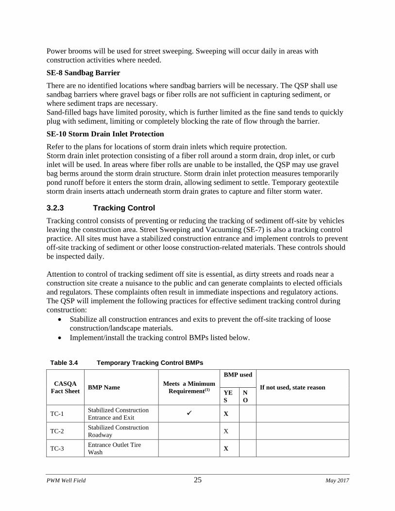
PWM Well Field 25 May 2017
Power brooms will be used for street sweeping. Sweeping will occur daily in areas with
construction activities where needed.
SE-8 Sandbag Barrier
There are no identified locations where sandbag barriers will be necessary. The QSP shall use
sandbag barriers where gravel bags or fiber rolls are not sufficient in capturing sediment, or
where sediment traps are necessary.
Sand-filled bags have limited porosity, which is further limited as the fine sand tends to quickly
plug with sediment, limiting or completely blocking the rate of flow through the barrier.
SE-10 Storm Drain Inlet Protection
Refer to the plans for locations of storm drain inlets which require protection.
Storm drain inlet protection consisting of a fiber roll around a storm drain, drop inlet, or curb
inlet will be used. In areas where fiber rolls are unable to be installed, the QSP may use gravel
bag berms around the storm drain structure. Storm drain inlet protection measures temporarily
pond runoff before it enters the storm drain, allowing sediment to settle. Temporary geotextile
storm drain inserts attach underneath storm drain grates to capture and filter storm water.
3.2.3 Tracking Control
Tracking control consists of preventing or reducing the tracking of sediment off-site by vehicles
leaving the construction area. Street Sweeping and Vacuuming (SE-7) is also a tracking control
practice. All sites must have a stabilized construction entrance and implement controls to prevent
off-site tracking of sediment or other loose construction-related materials. These controls should
be inspected daily.
Attention to control of tracking sediment off site is essential, as dirty streets and roads near a
construction site create a nuisance to the public and can generate complaints to elected officials
and regulators. These complaints often result in immediate inspections and regulatory actions.
The QSP will implement the following practices for effective sediment tracking control during
construction:
• Stabilize all construction entrances and exits to prevent the off-site tracking of loose
construction/landscape materials.
• Implement/install the tracking control BMPs listed below.
Table 3.4 Temporary Tracking Control BMPs
CASQA
Fact Sheet BMP Name
Meets a Minimum
Requirement(1)
BMP used
If not used, state reason
YE
S
N
O
TC-1 Stabilized Construction
Entrance and Exit ✓ X
TC-2 Stabilized Construction
Roadway X
TC-3 Entrance Outlet Tire
Wash X
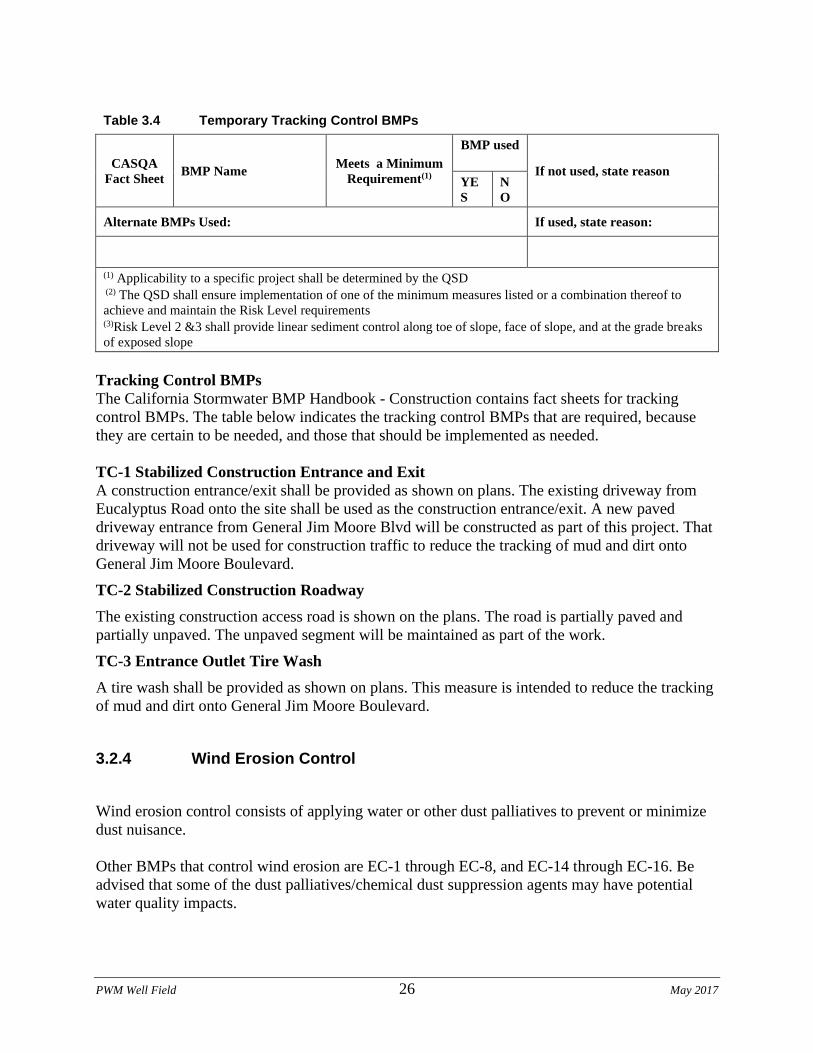
PWM Well Field 26 May 2017
Table 3.4 Temporary Tracking Control BMPs
CASQA
Fact Sheet BMP Name
Meets a Minimum
Requirement(1)
BMP used
If not used, state reason
YE
S
N
O
Alternate BMPs Used: If used, state reason:
(1) Applicability to a specific project shall be determined by the QSD (2) The QSD shall ensure implementation of one of the minimum measures listed or a combination thereof to
achieve and maintain the Risk Level requirements (3)Risk Level 2 &3 shall provide linear sediment control along toe of slope, face of slope, and at the grade breaks
of exposed slope
Tracking Control BMPs
The California Stormwater BMP Handbook - Construction contains fact sheets for tracking
control BMPs. The table below indicates the tracking control BMPs that are required, because
they are certain to be needed, and those that should be implemented as needed.
TC-1 Stabilized Construction Entrance and Exit
A construction entrance/exit shall be provided as shown on plans. The existing driveway from
Eucalyptus Road onto the site shall be used as the construction entrance/exit. A new paved
driveway entrance from General Jim Moore Blvd will be constructed as part of this project. That
driveway will not be used for construction traffic to reduce the tracking of mud and dirt onto
General Jim Moore Boulevard.
TC-2 Stabilized Construction Roadway
The existing construction access road is shown on the plans. The road is partially paved and
partially unpaved. The unpaved segment will be maintained as part of the work.
TC-3 Entrance Outlet Tire Wash
A tire wash shall be provided as shown on plans. This measure is intended to reduce the tracking
of mud and dirt onto General Jim Moore Boulevard.
3.2.4 Wind Erosion Control
Wind erosion control consists of applying water or other dust palliatives to prevent or minimize
dust nuisance.
Other BMPs that control wind erosion are EC-1 through EC-8, and EC-14 through EC-16. Be
advised that some of the dust palliatives/chemical dust suppression agents may have potential
water quality impacts.
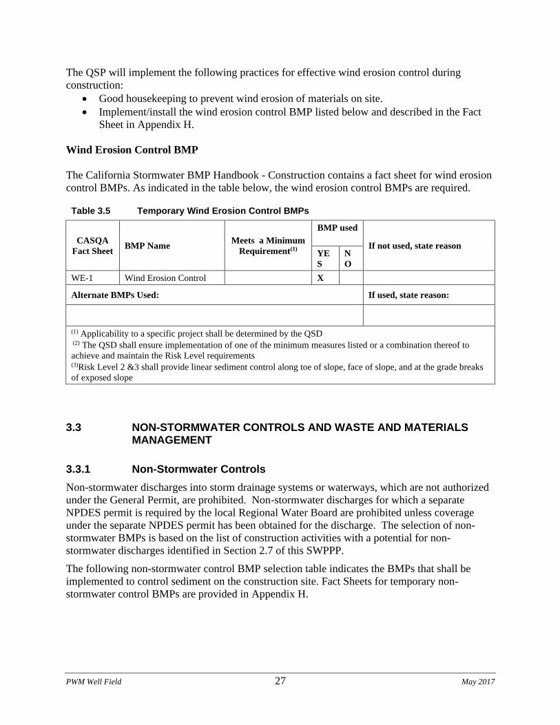
PWM Well Field 27 May 2017
The QSP will implement the following practices for effective wind erosion control during
construction:
• Good housekeeping to prevent wind erosion of materials on site.
• Implement/install the wind erosion control BMP listed below and described in the Fact
Sheet in Appendix H.
Wind Erosion Control BMP
The California Stormwater BMP Handbook - Construction contains a fact sheet for wind erosion
control BMPs. As indicated in the table below, the wind erosion control BMPs are required.
Table 3.5 Temporary Wind Erosion Control BMPs
CASQA
Fact Sheet BMP Name
Meets a Minimum
Requirement(1)
BMP used
If not used, state reason
YE
S
N
O
WE-1 Wind Erosion Control X
Alternate BMPs Used: If used, state reason:
(1) Applicability to a specific project shall be determined by the QSD (2) The QSD shall ensure implementation of one of the minimum measures listed or a combination thereof to
achieve and maintain the Risk Level requirements (3)Risk Level 2 &3 shall provide linear sediment control along toe of slope, face of slope, and at the grade breaks
of exposed slope
3.3 NON-STORMWATER CONTROLS AND WASTE AND MATERIALS MANAGEMENT
3.3.1 Non-Stormwater Controls
Non-stormwater discharges into storm drainage systems or waterways, which are not authorized
under the General Permit, are prohibited. Non-stormwater discharges for which a separate
NPDES permit is required by the local Regional Water Board are prohibited unless coverage
under the separate NPDES permit has been obtained for the discharge. The selection of non-
stormwater BMPs is based on the list of construction activities with a potential for non-
stormwater discharges identified in Section 2.7 of this SWPPP.
The following non-stormwater control BMP selection table indicates the BMPs that shall be
implemented to control sediment on the construction site. Fact Sheets for temporary non-
stormwater control BMPs are provided in Appendix H.
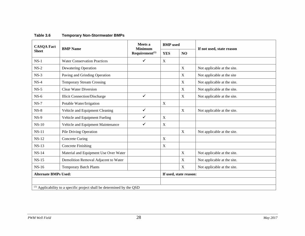
PWM Well Field 28 May 2017
Table 3.6 Temporary Non-Stormwater BMPs
CASQA Fact
Sheet BMP Name
Meets a
Minimum
Requirement(1)
BMP used If not used, state reason
YES NO
NS-1 Water Conservation Practices ✓ X
NS-2 Dewatering Operation X Not applicable at the site.
NS-3 Paving and Grinding Operation X Not applicable at the site
NS-4 Temporary Stream Crossing X Not applicable at the site.
NS-5 Clear Water Diversion X Not applicable at the site.
NS-6 Illicit Connection/Discharge ✓ X Not applicable at the site.
NS-7 Potable Water/Irrigation X
NS-8 Vehicle and Equipment Cleaning ✓ X Not applicable at the site.
NS-9 Vehicle and Equipment Fueling ✓ X
NS-10 Vehicle and Equipment Maintenance ✓ X
NS-11 Pile Driving Operation X Not applicable at the site.
NS-12 Concrete Curing X
NS-13 Concrete Finishing X
NS-14 Material and Equipment Use Over Water X Not applicable at the site.
NS-15 Demolition Removal Adjacent to Water X Not applicable at the site.
NS-16 Temporary Batch Plants X Not applicable at the site.
Alternate BMPs Used: If used, state reason:
(1) Applicability to a specific project shall be determined by the QSD
PWM Well Field Phase 3 29 August 2020
Non-stormwater BMPs shall be implemented in conformance with the following guidelines and
in accordance with the BMP Fact Sheets provided in Appendix H. If there is a conflict between
documents, the Site Map will prevail over narrative in the body of the SWPPP or guidance in the
BMP Fact Sheets. Site specific details in the Site Map prevail over standard details included in
the Site Map. The narrative in the body of the SWPPP prevails over guidance in the BMP Fact
Sheets.
NS-1 Water Conservation Practices
Practice suitable for all construction sites where water is used, including piped water, metered
water, trucked water, and water from a reservoir.
The following practices shall be implemented:
• Keep water equipment in good working condition.
• Stabilize water truck filling area.
• Repair water leaks promptly.
• Washing of vehicles and equipment on the construction site is discouraged.
• Avoid using water to clean construction areas. If water must be used for cleaning or
surface preparation, surface shall be swept and vacuumed first to remove dirt. This will
minimize amount of water required.
• Direct construction water runoff to areas where it can soak into the ground or be collected
and reused.
• Authorized non-stormwater discharges to the storm drain system, channels, or receiving
waters are acceptable with the implementation of appropriate BMPs. • Lock water tank valves to prevent unauthorized use.
• Cleaning.
NS-7 Potable Water/Irrigation
Potable water will be brought at the site and maintained in the following manner:
• Direct water from offsite sources around or through a construction site, where feasible, in
a way that minimizes contact with the construction site.
• Shut off the water source to broken lines, sprinklers, or valves as soon as possible to
prevent excess water flow.
NS-9 Vehicle and Equipment Fueling
Vehicle equipment fueling procedures are designed to prevent fuel spills and leaks, and reduce or
eliminate contamination of stormwater. This can be accomplished by using offsite facilities,
fueling in designated areas only, enclosing or covering stored fuel, implementing spill controls,
and training employees and subcontractors in proper fueling procedures.
Implementation recommendations:
PWM Well Field Phase 3 30 August 2020
• Use offsite fueling stations as much as possible. These businesses are better equipped to
handle fuel and spills properly. Performing this work offsite can also be economical by
eliminating the need for a separate fueling area at a site.
• Discourage “topping-off” of fuel tanks.
• Absorbent spill cleanup materials and spill kits shall be available in fueling areas and on
fueling trucks. Other options to washing equipment onsite include contracting with either
an offsite or mobile commercial be disposed of properly after use.
• Drip pans or absorbent pads shall be used during vehicle and equipment fueling, unless
the fueling is performed over an impermeable surface in a dedicated fueling area.
• Use absorbent materials on small spills. Do not hose down or bury the spill. Remove the
adsorbent materials promptly and dispose of properly.
• Avoid mobile fueling of mobile construction equipment around the site; rather, transport
the equipment to designated fueling areas. With the exception of tracked equipment such
as bulldozers and large excavators, most vehicles shall be able to travel to a designated
area with little lost time.
• Train employees and subcontractors in proper fueling and cleanup procedures.
• When fueling must take place onsite, designate an area away from drainage courses to be
used. Fueling areas shall be identified in the SWPPP.
• Dedicated fueling areas shall be protected from stormwater run-on and runoff, and shall
be located at least 50 ft away from downstream drainage facilities and watercourses.
Fueling must be performed on level-grade areas.
• Protect fueling areas with berms and dikes to prevent run-on, runoff, and to contain spills.
• Nozzles used in vehicle and equipment fueling shall be equipped with an automatic
shutoff to control drips. Fueling operations shall not be left unattended.
• Use vapor recovery nozzles to help control drips as well as air pollution where required
by Air Quality Management District (AQMD).
• Federal, state, and local requirements shall be observed for any stationary above ground
storage tanks.
NS-10 Vehicle and Equipment Maintenance
Prevent or reduce the contamination of stormwater resulting from vehicle and equipment
maintenance by running a “dry and clean site”. The best option would be to perform maintenance
activities at an offsite facility. If this option is not available, then work should be performed in
designated areas only, while providing cover for materials stored outside, checking for leaks and
spills, and containing and cleaning up spills immediately. Employees and subcontractors must be
trained in proper procedures.
Implementation recommendations:
• Use offsite repair shops as much as possible. These businesses are better equipped to
handle vehicle fluids and spills properly. Performing this work offsite can also be
economical by eliminating the need for a separate maintenance area.
• If maintenance must occur onsite, use designated areas, located away from drainage
courses. Dedicated maintenance areas shall be protected from stormwater run-on and
runoff, and shall be located at least 50 ft from downstream drainage facilities.
PWM Well Field Phase 3 31 August 2020
• Drip pans or absorbent pads shall be used during vehicle and equipment maintenance
work that involves fluids, unless the maintenance work is performed over an
impermeable surface in a dedicated maintenance area.
• Place a stockpile of spill cleanup materials where it will be readily accessible. All fueling
trucks and fueling areas are required to have spill kits and/or use other spill protection
devices.
• Use adsorbent materials on small spills. Remove the absorbent materials promptly and
dispose of properly.
• Inspect onsite vehicles and equipment daily at startup for leaks, and repair immediately.
• Keep vehicles and equipment clean; do not allow excessive build-up of oil and grease.
• Segregate and recycle wastes, such as greases, used oil or oil filters, antifreeze, cleaning
solutions, automotive batteries, hydraulic and transmission fluids. Provide secondary
containment and covers for these materials if stored onsite.
• Train employees and subcontractors in proper maintenance and spill cleanup procedures.
• Drip pans or plastic sheeting shall be placed under all vehicles and equipment placed on
docks, barges, or other structures over water bodies when the vehicle or equipment is
planned to be idle for more than 1 hour.
• For long-term projects, consider using portable tents or covers over maintenance areas if
maintenance cannot be performed offsite.
• Consider use of new, alternative greases and lubricants, such as adhesive greases, for
chassis lubrication and fifth-wheel lubrication.
• Properly dispose of used oils, fluids, lubricants, and spill cleanup materials.
• Do not place used oil in a dumpster or pour into a storm drain or watercourse.
• Properly dispose of or recycle used batteries.
• Do not bury used tires.
NS-12 Concrete Curing
Concrete and its associated curing materials have basic chemical properties that can raise the pH
of water to levels outside of the permitted range. Discharges of stormwater and non-stormwater
exposed to concrete during curing may have a high pH and may contain chemicals, metals, and
fines. Proper procedures and care should be taken when managing concrete curing materials to
prevent them from coming into contact with stormwater flows, which could result in high pH
discharge.
Implementation recommendations:
Chemical Curing
• Avoid over spray of curing compounds.
• Minimize the drift by applying the curing compound close to the concrete surface. Apply
an amount of compound that covers the surface, but does not allow any runoff of the
compound.
• Use proper storage and handling techniques for concrete curing compounds. Refer to
WM-1, Material Delivery and Storage.
• Protect drain inlets prior to the application of curing compounds.
PWM Well Field Phase 3 32 August 2020
• Refer to WM-4, Spill Prevention and Control.
Water Curing for Retaining Walls, and other Structures
• Direct cure water away from inlets and watercourses to collection areas for evaporation
or other means of removal in accordance with all applicable permits. See WM-8 Concrete
Waste Management.
• Collect cure water at the top of slopes and transport to a concrete waste management area
in a non-erosive manner. See EC-9 Earth Dikes and Drainage Swales, and EC-10,
Velocity Dissipation Devices.
• Utilize wet blankets or a similar method that maintains moisture while minimizing the
use and possible discharge of water.
Education
• Educate employees, subcontractors, and suppliers on proper concrete curing techniques to
prevent contact with discharge as described herein. Arrange for the QSP or the
appropriately trained contractor’s superintendent or representative to oversee and enforce
concrete curing procedures.
NS-13 Concrete Finishing
Concrete finishing methods are used for paint removal, curing compound removal, and final
surface finish appearances. Methods include sand blasting, shot blasting, grinding, or high
pressure water blasting. Stormwater and non-stormwater exposed to concrete finishing by-
products may have a high pH and may contain chemicals, metals, and fines. Proper procedures
and implementation of appropriate BMPs can minimize the impact that concrete-finishing
methods may have on stormwater and non-stormwater discharges.
Implementation recommendations:
• Collect and properly dispose of water from high-pressure water blasting operations.
• Collect contaminated water from blasting operations at the top of slopes. Transport or
dispose of contaminated water while using BMPs such as those for erosion control. Refer
to EC-9, Earth
• Dikes and Drainage Swales, and EC-10, Velocity Dissipation Devices.
• Direct water from blasting operations away from inlets and watercourses to collection
areas for infiltration or other means of removal (dewatering). Refer to NS-2 Dewatering
Operations.
• Protect inlets during sandblasting operations. Refer to SE-10, Storm Drain Inlet
Protection.
• Refer to WM-8, Concrete Waste Management for disposal of concrete debris.
• Minimize the drift of dust and blast material as much as possible by keeping the blasting
nozzle close to the surface.
• When blast residue contains a potentially hazardous waste, refer to WM-6, Hazardous
Waste Management.
Education
PWM Well Field Phase 3 33 August 2020
Educate employees, subcontractors, and suppliers on proper concrete finishing techniques to
prevent contact with discharge as described herein. Arrange for the QSP or the appropriately
trained contractor’s superintendent or representative to oversee and enforce concrete finishing
procedures.
3.3.2 Materials Management and Waste Management
Materials management control practices consist of implementing procedural and structural BMPs
for handling, storing and using construction materials to prevent the release of those materials
into stormwater discharges. The amount and type of construction materials to be utilized at the
Site will depend upon the type of construction and the length of the construction period. The
materials may be used continuously, such as fuel for vehicles and equipment, or the materials
may be used for a discrete period, such as soil binders for temporary stabilization.
Waste management consist of implementing procedural and structural BMPs for handling,
storing and ensuring proper disposal of wastes to prevent the release of those wastes into
stormwater discharges.
Materials and waste management pollution control BMPs shall be implemented to minimize
stormwater contact with construction materials, wastes and service areas; and to prevent
materials and wastes from being discharged off-site. The primary mechanisms for stormwater
contact that shall be addressed include:
• Direct contact with precipitation
• Contact with stormwater run-on and runoff
• Wind dispersion of loose materials
• Direct discharge to the storm drain system through spills or dumping
• Extended contact with some materials and wastes, such as asphalt cold mix and treated
wood products, which can leach pollutants into stormwater.
A list of construction activities is provided in Section 2.6. The following Materials and Waste
Management BMP selection table indicates the BMPs that shall be implemented to handle
materials and control construction site wastes associated with these construction activities. Fact
Sheets for Materials and Waste Management BMPs are provided in Appendix H.
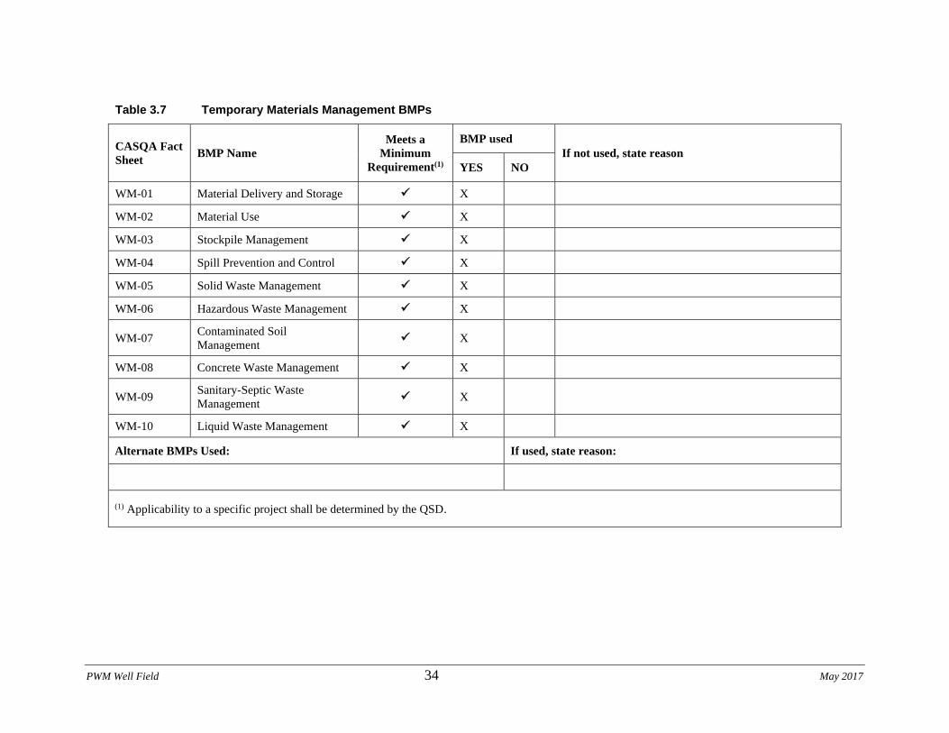
PWM Well Field 34 May 2017
Table 3.7 Temporary Materials Management BMPs
CASQA Fact
Sheet BMP Name
Meets a
Minimum
Requirement(1)
BMP used
If not used, state reason
YES NO
WM-01 Material Delivery and Storage ✓ X
WM-02 Material Use ✓ X
WM-03 Stockpile Management ✓ X
WM-04 Spill Prevention and Control ✓ X
WM-05 Solid Waste Management ✓ X
WM-06 Hazardous Waste Management ✓ X
WM-07 Contaminated Soil
Management ✓ X
WM-08 Concrete Waste Management ✓ X
WM-09 Sanitary-Septic Waste
Management ✓ X
WM-10 Liquid Waste Management ✓ X
Alternate BMPs Used: If used, state reason:
(1) Applicability to a specific project shall be determined by the QSD.
PWM Well Field Phase 3 35 August 2020
Material management BMPs shall be implemented in conformance with the following guidelines
and in accordance with the BMP Fact Sheets provided in Appendix H. If there is a conflict
between documents, the Site Map will prevail over narrative in the body of the SWPPP or
guidance in the BMP Fact Sheets. Site specific details in the Site Map prevail over standard
details included in the Site Map. The narrative in the body of the SWPPP prevails over guidance
in the BMP Fact Sheets.
WM-1 Material Delivery and Storage
The following steps shall be taken to minimize risk:
• Chemicals must be stored in water tight containers with appropriate secondary
containment or in a storage shed.
• When a material storage area is located on bare soil, the area shall be lined and bermed.
• Use containment pallets or other practical and available solutions, such as storing
materials within newly constructed buildings or garages, to meet material storage
requirements.
• Stack erodible landscape material on pallets and cover when not in use.
• Contain all fertilizers and other landscape materials when not in use.
• Temporary storage areas shall be located away from vehicular traffic.
• Material Safety Data Sheets (MSDS) shall be available on-site for all materials stored
that have the potential to effect water quality.
• Construction site areas shall be designated for material delivery and storage.
• Material delivery and storage areas shall be located away from waterways, if possible.
o Avoid transport near drainage paths or waterways.
o Surround with earth berms or other appropriate containment BMP. See EC-9,
Earth Dikes and Drainage Swales.
o Place in an area that will be paved.
• Storage of reactive, ignitable, or flammable liquids must comply with the fire codes of
the area. Contact the local Fire Marshal to review site materials, quantities, and proposed
storage area to determine specific requirements. See the Flammable and Combustible
Liquid Code, NFPA30.
• An up to date inventory of materials delivered and stored onsite shall be kept. Hazardous
materials storage onsite shall be minimized.
• Hazardous materials shall be handled as infrequently as possible.
• Keep ample spill cleanup supplies appropriate for the materials being stored. Ensure that
cleanup supplies are in a conspicuous, labeled area.
• Employees and subcontractors shall be trained on the proper material delivery and
storage practices.
• Employees trained in emergency spill cleanup procedures must be present when
dangerous materials or liquid chemicals are unloaded.
• If significant residual materials remain on the ground after construction is complete,
properly remove and dispose of materials and any contaminated soil. See WM-7,
Contaminated Soil Management. If the area is to be paved, pave as soon as materials are
removed to stabilize the soil.
Material Storage Areas and Practices
PWM Well Field Phase 3 36 August 2020
• Liquids, petroleum products, and substances listed in 40 CFR Parts 110, 117, or 302 shall
be stored in approved containers and drums and shall not be overfilled. Containers and
drums shall be placed in temporary containment facilities for storage.
• A temporary containment facility shall provide for a spill containment volume able to
contain precipitation from a 25 year storm event, plus the greater of 10% of the aggregate
volume of all containers or 100% of the capacity of the largest container within its
boundary, whichever is greater.
• A temporary containment facility shall be impervious to the materials stored therein for a
minimum contact time of 72 hours.
• A temporary containment facility shall be maintained free of accumulated rainwater and
spills. In the event of spills or leaks, accumulated rainwater and spills shall be collected
and placed into drums. These liquids shall be handled as a hazardous waste unless testing
determines them to be non-hazardous. All collected liquids or non-hazardous liquids shall
be sent to an approved disposal site.
• Sufficient separation shall be provided between stored containers to allow for spill
cleanup and emergency response access.
• Incompatible materials, such as chlorine and ammonia, shall not be stored in the same
temporary containment facility.
• Materials shall be covered prior to, and during rain events.
• Materials shall be stored in their original containers and the original product labels shall
be maintained in place in a legible condition. Damaged or otherwise illegible labels shall
be replaced immediately.
• Bagged and boxed materials shall be stored on pallets and shall not be allowed to
accumulate on the ground. To provide protection from wind and rain throughout the rainy
season, bagged and boxed materials shall be covered during non-working days and prior
to and during rain events.
• Stockpiles shall be protected in accordance with WM-3, Stockpile Management.
• Materials shall be stored indoors within existing structures or completely enclosed
storage sheds when available.
• Proper storage instructions shall be posted at all times in an open and conspicuous
location.
• An ample supply of appropriate spill cleanup material shall be kept near storage areas.
• Also see WM-6, Hazardous Waste Management, for storing of hazardous wastes.
Material Delivery Practices
Keep an accurate, up-to-date inventory of material delivered and stored onsite.
Arrange for employees trained in emergency spill cleanup procedures to be present when
dangerous materials or liquid chemicals are unloaded.
Spill Cleanup
• Contain and clean up any spill immediately.
• Properly remove and dispose of any hazardous materials or contaminated soil if
significant residual materials remain on the ground after construction is complete. See
WM-7, Contaminated
PWM Well Field Phase 3 37 August 2020
• Soil Management.
• See WM-4, Spill Prevention and Control, for spills of chemicals and/or hazardous
materials. If spills or leaks of materials occur that are not contained and could discharge
to surface waters, non-visible sampling of site discharge may be required. Refer to the
General Permit or to your project specific Construction Site Monitoring Plan to determine
if and where sampling is required.
WM-2 Material Use
The following steps shall be taken to minimize risk:
• Minimize use of hazardous materials onsite.
• Follow manufacturer instructions regarding uses, protective equipment, ventilation,
flammability, and mixing of chemicals.
• Train personnel who use pesticides. The California Department of Pesticide Regulation
and
• County Agricultural Commissioners license pesticide dealers, certify pesticide
applicators, and conduct onsite inspections.
• Train employees and subcontractors in proper material use.
• Supply Material Safety Data Sheets (MSDS) for all materials.
• Dispose of latex paint and paint cans, used brushes, rags, absorbent materials, and drop
cloths, when thoroughly dry and are no longer hazardous, with other construction debris.
• Do not remove the original product label; it contains important safety and disposal
information. Use the entire product before disposing of the container.
• Mix paint indoors or in a containment area. Never clean paintbrushes or rinse paint
containers into a street, gutter, storm drain, or watercourse. Dispose of any paint thinners,
residue, and sludge(s) that cannot be recycled, as hazardous waste.
• For water-based paint, clean brushes to the extent practicable, and rinse to a drain leading
to a sanitary sewer where permitted, or contain for proper disposal off site. For oil-based
paints, clean brushes to the extent practicable, and filter and reuse thinners and solvents.
• Use recycled and less hazardous products when practical. Recycle residual paints,
solvents, nontreated lumber, and other materials.
• Use materials only where and when needed to complete the construction activity. Use
safer alternative materials as much as possible. Reduce or eliminate use of hazardous
materials onsite when practical.
• Document the location, time, chemicals applied, and applicator’s name and
qualifications.
• Keep an ample supply of spill cleanup material near use areas. Train employees in spill
cleanup procedures.
• Avoid exposing applied materials to rainfall and runoff unless sufficient time has been
allowed for them to dry.
• Discontinue use of erodible landscape material within 2 days prior to a forecasted rain
event and materials shall be covered and/or bermed.
• Provide containment for material use areas such as masons’ areas or paint
mixing/preparation areas to prevent materials/pollutants from entering stormwater.
PWM Well Field Phase 3 38 August 2020
WM-3 Stockpile Management
Stockpiling of material is anticipated at the construction site. Contractor shall cover all stockpiles
that are not being used at the end of the day. Stockpiles not used for 14 days shall be removed
from the site. Dust control measures will be implemented on any stockpiled materials.
WM-4 Spill Prevention and Control
Employees will be trained to identify the type of spill (Minor, Semi-Significant or
Significant/Hazardous), and respond accordingly. Spills will not be cleaned up using water. The
spills will be cleaned up using materials specified for the type of spill. The used clean up
material and the recovered materials no longer suitable for the intended purpose will be disposed
off site as per the applicable regulations. Regular meetings will be held to discuss these
procedures as continuing education for new employees. Keep material or waste storage areas
clean, well-organized, and equipped with enough cleanup supplies for the material being stored.
Implement spill and leak prevention procedures for chemicals and hazardous substances stored
on the job site. Whenever you spill or leak chemicals or hazardous substances at the job site, you
are responsible for all associated cleanup costs and related liability.
Report minor, semi-significant, and significant or hazardous spills to the WPC manager. The
WPC manager must notify the Engineer immediately. As soon as it is safe, contain and clean up
spills of petroleum materials and sanitary and septic waste substances listed under 40 CFR, Parts
110, 117, and 302.
Minor Spills
Minor spills consist of quantities of oil, gasoline, paint, or other materials that are small enough
to be controlled by a 1st responder upon discovery of the spill.
Clean up a minor spill using the following procedures:
1. Contain the spread of the spill
2. Recover the spilled material using absorption
3. Clean the contaminated area
4. Dispose of the contaminated material and absorbents promptly and properly under "Waste
Management" of these special provisions
Semi-Significant Spills
Semi-significant spills consist of spills that can be controlled by a 1st responder with help from
other personnel.
Clean up a semi-significant spill immediately using the following procedures:
1. Contain the spread of the spill.
2. On paved or impervious surfaces, encircle and recover the spilled material with absorbent
materials. Do not allow the spill to spread widely.
3. If the spill occurs on soil, contain the spill by constructing an earthen dike and dig up the
contaminated soil for disposal.
4. If the spill occurs during precipitation, cover the spill with 10-mil plastic sheeting or other
material to prevent contamination of runoff.
PWM Well Field Phase 3 39 August 2020
5. Dispose of the contaminated material promptly and properly under "Waste Management" of
these special provisions.
Significant or Hazardous Spills
Significant or hazardous spills consist of spills that cannot be controlled by job site personnel.
Immediately notify qualified personnel of a significant or hazardous spill. Take the following
steps:
1. Do not attempt to clean up the spill until qualified personnel have arrived
2. Notify the Engineer and follow up with a report
3. Obtain the immediate services of a spill contractor or hazardous material team
4. Notify local emergency response teams by dialing 911 and county officials by using the
emergency phone numbers retained at the job site
5. Notify the California Emergency Management Agency State Warning Center.
6. Notify the National Response Center at (800) 424-8802 regarding spills of Federal reportable
quantities under 40 CFR 110, 119, and 302
7. Notify other agencies as appropriate, including:
o Fire Department
o Public Works Department
o Coast Guard
o Highway Patrol
o City Police or County Sheriff's Department
o Department of Toxic Substances
o California Division of Oil and Gas
o Cal/OSHA
o Regional Water Resources Control Board
8. Prevent a spill from entering stormwater runoff before and during cleanup activities. Do
not bury or wash the spill with water.
WM-5 Solid Waste Management
The following steps shall be taken to help keep a clean site and reduce stormwater pollution:
• Select designated waste collection areas onsite.
• Inform trash-hauling contractors that the site will accept only watertight dumpsters for
onsite use.
• Inspect dumpsters for leaks and repair any dumpster that is not watertight.
• Locate containers in a covered area or in a secondary containment.
• Provide an adequate number of containers with lids or covers that can be placed over the
container to keep rain out or to prevent loss of wastes when it is windy.
• Plan for additional containers and more frequent pickup during the demolition phase of
construction.
• Collect site trash daily, especially during rainy and windy conditions.
• Remove solid waste promptly since erosion and sediment control devices tend to collect
litter.
• Make sure that toxic liquid wastes (used oils, solvents, and paints) and chemicals (acids,
pesticides, additives, curing compounds) are not disposed of in dumpsters designated for
PWM Well Field Phase 3 40 August 2020
construction debris.
• Do not hose out dumpsters on the construction site. Leave dumpster cleaning to the trash
hauling contractor.
• Arrange for regular waste collection before containers overflow.
• Clean up immediately if a container does spill.
• Make sure that construction waste is collected, removed, and disposed of only at
authorized disposal areas.
Regular meetings will be held to discuss these procedures as continuing education for new
employees.
Collection, Storage, and Disposal
• Littering on the project site is prohibited.
• To prevent clogging of the storm drainage system, litter and debris removal from
drainage grates, trash racks, and ditch lines is a priority.
• Trash receptacles shall be provided in the contractor’s yard, field trailer areas, and at
locations where workers congregate for lunch and break periods.
• Litter from work areas within the construction limits of the project site shall be collected
and placed in watertight dumpsters at least weekly, regardless of whether the litter was
generated by the contractor, the public, or others. Collected litter and debris shall not be
placed in or next to stormwater drainage systems, or watercourses.
• Dumpsters of sufficient size and number shall be provided to contain the solid waste
generated by the project.
• Full dumpsters shall be removed from the project site and the contents shall be disposed
of by the trash hauling contractor.
• Construction debris and waste shall be removed from the site biweekly or more
frequently as needed.
• Construction material visible to the public shall be stored or stacked in an orderly
manner.
• Stormwater run-on shall be prevented from contacting stored solid waste through the use
of berms, dikes, or other temporary diversion structures or through the use of measures to
elevate waste from site surfaces.
• Solid waste storage areas shall be located at least 50 ft from drainage facilities and
watercourses and shall not be located in areas prone to flooding or ponding.
• Except during fair weather, construction and highway planting waste not stored in
watertight dumpsters shall be securely covered from wind and rain by covering the waste
with tarps or plastic.
• Segregate potentially hazardous waste from non-hazardous construction site waste.
• Make sure that toxic liquid wastes (used oils, solvents, and paints) and chemicals (acids,
pesticides, additives, curing compounds) are not disposed of in dumpsters designated for
construction debris.
• For disposal of hazardous waste, see WM-6, Hazardous Waste Management. Have
hazardous waste hauled to an appropriate disposal and/or recycling facility.
• Salvage or recycle useful vegetation debris, packaging and surplus building materials
when practical. For example, trees and shrubs from land clearing can be used as a brush
PWM Well Field Phase 3 41 August 2020
barrier, or converted into wood chips, then used as mulch on graded areas. Wood pallets,
cardboard boxes, and construction scraps can also be recycled.
WM-6 Hazardous Waste Management
Hazardous Waste Management will be implemented as per the contract specifications for any
requirements pertaining to handling of contaminated material. Any waste generated will be
stored in watertight containers and stored in a location approved by the Engineer until it is
disposed of by a licensed hazardous waste transporter.
WM-7 Contaminated Soil Management
Prevent or reduce the discharge of pollutants to stormwater from contaminated soil and highly
acidic or alkaline soils by conducting pre-construction surveys, inspecting excavations regularly,
and remediating contaminated soil promptly. Look for contaminated soil as evidenced by
discoloration, odors, differences in soil properties, abandoned underground tanks or pipes, or
buried debris. Prevent leaks and spills. Contaminated soil can be expensive to treat and dispose
of properly. However, addressing the problem before construction is much less expensive than
after the structures are in place. The contractor may further identify contaminated soils by
investigating:
• Past site uses and activities
• Detected or undetected spills and leaks
• Acid or alkaline solutions from exposed soil or rock formations high in acid or alkaline
forming elements
• Contaminated soil as evidenced by discoloration, odors, differences in soil properties,
abandoned underground tanks or pipes, or buried debris.
• Suspected soils should be tested at a certified laboratory
WM-8 Concrete Waste Management
Concrete waste will be handled in accordance with contract documents. Collect and dispose of
Portland concrete, AC, or HMA waste at locations where saw-cutting, coring, grinding, grooving
or hydro-concrete demolition of Portland cement concrete, AC or HMA create a residue or
slurry. Concrete waste will be collected and disposed as appropriate portable washout bins. If
any spilled material is observed, the spilled material shall be removed and placed into the
concrete washout bin. WM-4 Spill Prevention and Control BMPs shall be implemented in case
of any spill.
WM-9 Sanitary/Septic Waste Management
Sanitary or septic wastes shall be treated or disposed of in accordance with state and local
requirements. The sanitary facilities shall be located at least 50 feet away from storm drains. The
weekly QSP inspection shall include a review of sanitary facilities and disposal shall be
monitored.
PWM Well Field Phase 3 42 August 2020
WM-10 Liquid Waste Management
Well drilling fluids will be hauled off-site for disposal at a licensed wastewater treatment facility
in accordance with the contract documents.
3.4 POST CONSTRUCTION STORMWATER MANAGEMENT MEASURES
Post construction BMPs are permanent measures installed during construction, designed to
reduce or eliminate pollutant discharges from the site after construction is completed.
This site is located in an area subject to a Phase I or Phase II Municipal Separate Storm Sewer
System (MS4) permit approved Stormwater Management Plan. Yes No
The following source control post construction BMPs to comply with General Permit Section
XIII.B and local requirements have been identified for the site:
• Local percolation basins (seepage pits) are incldued on several well sites to handle
local run-off. These will be inspected and cleaned periodically.
• The main backwash percolation basin will be periodcally maintained by removing
accumulated silt and scarifying the pond bottom.
A plan for the post construction funding and maintenance of these BMPs has been developed to
address at minimum five years following construction. The post construction BMPs that are
described above shall be funded and maintained by the LRP. If required, post construction
funding and maintenance will be submitted with the NOT.
PWM Well Field Phase 3 43 August 2020
Section 4 BMP Inspection, Maintenance, and Rain
Event Action Plans
4.1 BMP INSPECTION AND MAINTENANCE
The General Permit requires routine weekly inspections of BMPs, along with inspections before,
during, and after qualifying rain events. A BMP inspection checklist must be filled out for
inspections and maintained on-site with the SWPPP. The inspection checklist includes the
necessary information covered in Section 7.6. A blank inspection checklist can be found in
Appendix I. Completed checklists shall be kept in CSMP Attachment 2 “Monitoring Records.
BMPs shall be maintained regularly to ensure proper and effective functionality. If necessary,
corrective actions shall be implemented within 72 hours of identified deficiencies and associated
amendments to the SWPPP shall be prepared by the QSD.
Specific details for maintenance, inspection, and repair of Construction Site BMPs can be found
in the BMP Factsheets in Appendix H.
4.2 RAIN EVENT ACTION PLANS
Rain Event Action Plans (REAPs) are not required for Risk Level 1 projects.
PWM Well Field Phase 3 44 August 2020
Section 5 Training
Appendix L identifies the QSPs for the project. To promote stormwater management awareness
specific for this project, periodic training of job-site personnel shall be included as part of routine
project meetings (e.g. daily/weekly tailgate safety meetings), or task specific trainings as needed.
The QSP shall be responsible for providing this information at the meetings, and subsequently
completing the training logs shown in Appendix K, which identifies the site-specific stormwater
topics covered as well as the names of site personnel who attended the meeting. Tasks may be
delegated to trained employees by the QSP provided adequate supervision and oversight is
provided. Training shall correspond to the specific task delegated including: SWPPP
implementation; BMP inspection and maintenance; and record keeping.
Documentation of training activities (formal and informal) is retained in SWPPP Appendix K.
PWM Well Field Phase 3 45 August 2020
Section 6 Responsible Parties and Operators
6.1 RESPONSIBLE PARTIES
Approved Signatories who are responsible for SWPPP implementation and have authority to sign
permit-related documents are listed below. Written authorizations from the LRP for these
individuals are provided in Appendix L. The Approved Signatories assigned to this project are:
Name Title Phone Number
Paul Sciuto , PE General Manager Monterey
One Water
(831) 645-4634
QSPs identified for the project are identified in Appendix L. The QSP shall have primary
responsibility and significant authority for the implementation, maintenance and
inspection/monitoring of SWPPP requirements. The QSP will be available at all times
throughout the duration of the project. Duties of the QSP include but are not limited to:
• Implementing all elements of the General Permit and SWPPP, including but not limited
to:
o Ensuring all BMPs are implemented, inspected, and properly maintained;
o Performing non-stormwater and stormwater visual observations and inspections;
o Performing non-stormwater and storm sampling and analysis, as required;
o Performing routine inspections and observations;
o Implementing non-stormwater management, and materials and waste management
activities such as: monitoring discharges; general Site clean-up; vehicle and
equipment cleaning, fueling and maintenance; spill control; ensuring that no materials
other than stormwater are discharged in quantities which will have an adverse effect
on receiving waters or storm drain systems; etc.;
• The QSP may delegate these inspections and activities to an appropriately trained
employee, but shall ensure adequacy and adequate deployment.
• Ensuring elimination of unauthorized discharges.
• The QSPs shall be assigned authority by the LRP to mobilize crews in order to make
immediate repairs to the control measures.
• Coordinate with the Contractor(s) to assure all of the necessary corrections/repairs are
made immediately and that the project complies with the SWPPP, the General Permit and
approved plans at all times.
• Notifying the LRP or Authorized Signatory immediately of off-site discharges or other
non-compliance events.
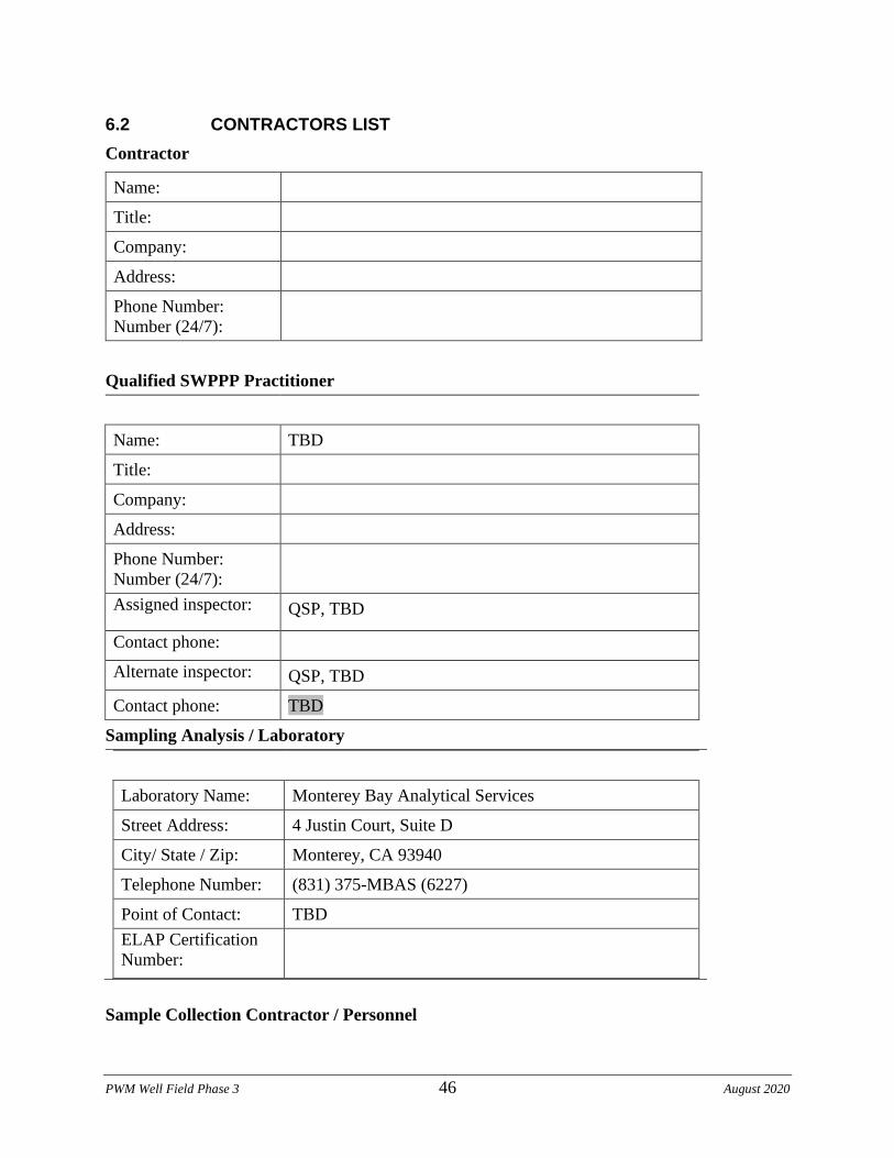
PWM Well Field Phase 3 46 August 2020
6.2 CONTRACTORS LIST
Contractor
Name:
Title:
Company:
Address:
Phone Number:
Number (24/7):
Qualified SWPPP Practitioner
Name: TBD
Title:
Company:
Address:
Phone Number:
Number (24/7):
Assigned inspector: QSP, TBD
Contact phone:
Alternate inspector: QSP, TBD
Contact phone: TBD
Sampling Analysis / Laboratory
Laboratory Name: Monterey Bay Analytical Services
Street Address: 4 Justin Court, Suite D
City/ State / Zip: Monterey, CA 93940
Telephone Number: (831) 375-MBAS (6227)
Point of Contact: TBD
ELAP Certification
Number:
Sample Collection Contractor / Personnel
PWM Well Field Phase 3 47 August 2020
Name: TBD
Title:
Company:
Address:
Phone Number:
Number (24/7):
Assigned inspector: QSP, TBD
Contact phone:
Alternate inspector: QSP, TBD
Contact phone: TBD
PWM Well Field Phase 3 48 August 2020
Section 7 Construction Site Monitoring Program
7.1 Purpose
This Construction Site Monitoring Program was developed to address the following objectives:
1. To demonstrate that the site is in compliance with the Discharge Prohibitions and
Numeric Action Levels (NALs) of the Construction General Permit;
2. To determine whether non-visible pollutants are present at the construction site and are
causing or contributing to exceedances of water quality objectives;
3. To determine whether immediate corrective actions, additional Best Management
Practices (BMP) implementation, or SWPPP revisions are necessary to reduce pollutants
in stormwater discharges and authorized non-stormwater discharges;
4. To determine whether BMPs included in the SWPPP and REAP are effective in
preventing or reducing pollutants in stormwater discharges and authorized non-
stormwater discharges.
7.2 Applicability of Permit Requirements
This project has been determined to be a Risk Level 1 project. The General Permit identifies the
following types of monitoring as being applicable for a Risk Level 1 project.
Risk Level 1
• Visual inspections of Best Management Practices (BMPs);
• Visual monitoring of the site related to qualifying storm events;
• Visual monitoring of the site for non-stormwater discharges;
• Sampling and analysis of construction site runoff for non-visible pollutants when
applicable; and
• Sampling and analysis of construction site runoff as required by the Regional Water
Board when applicable.
7.3. Weather and Rain Event Tracking
Visual monitoring and inspections requirements of the General Permit are triggered by a
qualifying rain event. The General Permit defines a qualifying rain event as any event that
produces ½ inch of precipitation. A minimum of 48 hours of dry weather will be used to
distinguish between separate qualifying storm events.
7.3.1 Weather Tracking
The QSP should daily consult the National Oceanographic and Atmospheric Administration
(NOAA) for the weather forecasts. These forecasts can be obtained at http://www.srh.noaa.gov/.
Weather reports should be printed and maintained with the SWPPP in CSMP Attachment 1
“Weather Reports”.
PWM Well Field Phase 3 49 August 2020
7.3.2 Rain Gauges
The QSP shall install 1 rain gauge on the project site. Locate the gauge in an open area away
from obstructions such as trees or overhangs. Mount the gauge on a post at a height of 3 to 5 feet
with the gauge extending several inches beyond the post. Make sure that the top of the gauge is
level. Make sure the post is not in an area where rainwater can indirectly splash from sheds,
equipment, trailers, etc.
The rain gauge shall be read daily during normal site scheduled hours. The rain gauge should be
read at approximately the same time every day and the date and time of each reading recorded.
Log rain gauge readings in CSMP Attachment 1 “Weather Records”. Follow the rain gauge
instructions to obtain accurate measurements.
Once the rain gauge reading has been recorded, accumulated rain shall be emptied and the gauge
reset. For comparison with the site rain gauge, the nearest appropriate governmental rain
gauge(s) is located at MONTEREY PENINSULA AIRPORT, Station GHCND:USW00023259.
7.4 Monitoring Locations
Monitoring locations are shown on the Erosion Control Plan in Appendix R. Monitoring
locations are described in the Sections 7.6 and 7.7.
Whenever changes in the construction site might affect the appropriateness of sampling
locations, the sampling locations shall be revised accordingly. All such revisions shall be
implemented as soon as feasible and the SWPPP amended. Temporary changes that result in a
one-time additional sampling location do not require a SWPPP amendment.
7.5 Safety and Monitoring Exemptions
Safety practices for sample collection will be in accordance with the Contractor’s Health and
Safety Plan. This project is not required to collect samples or conduct visual observations
(inspections) under the following conditions:
• During dangerous weather conditions such as flooding and electrical storms.
• Outside of scheduled site business hours.
Scheduled site business hours are: 7:00 a.m. to 5:00 p.m., Monday-Friday. 24-hour operations
during well drilling and development.
If monitoring (visual monitoring or sample collection) of the site is unsafe because of the
dangerous conditions noted above then the QSP shall document the conditions for why an
exception to performing the monitoring was necessary. The exemption documentation shall be
filed in CSMP Attachment 2 “Monitoring Records”.
7.6 Visual Monitoring
Visual monitoring includes observations and inspections. Inspections of BMPs are required to
identify and record BMPs that need maintenance to operate effectively, that have failed, or that
could fail to operate as intended. Visual observations of the site are required to observe storm
water drainage areas to identify any spills, leaks, or uncontrolled pollutant sources.
Table 7.1 identifies the required frequency of visual observations and inspections. Inspections
and observations will be conducted at the locations identified in Section 7.6.5.
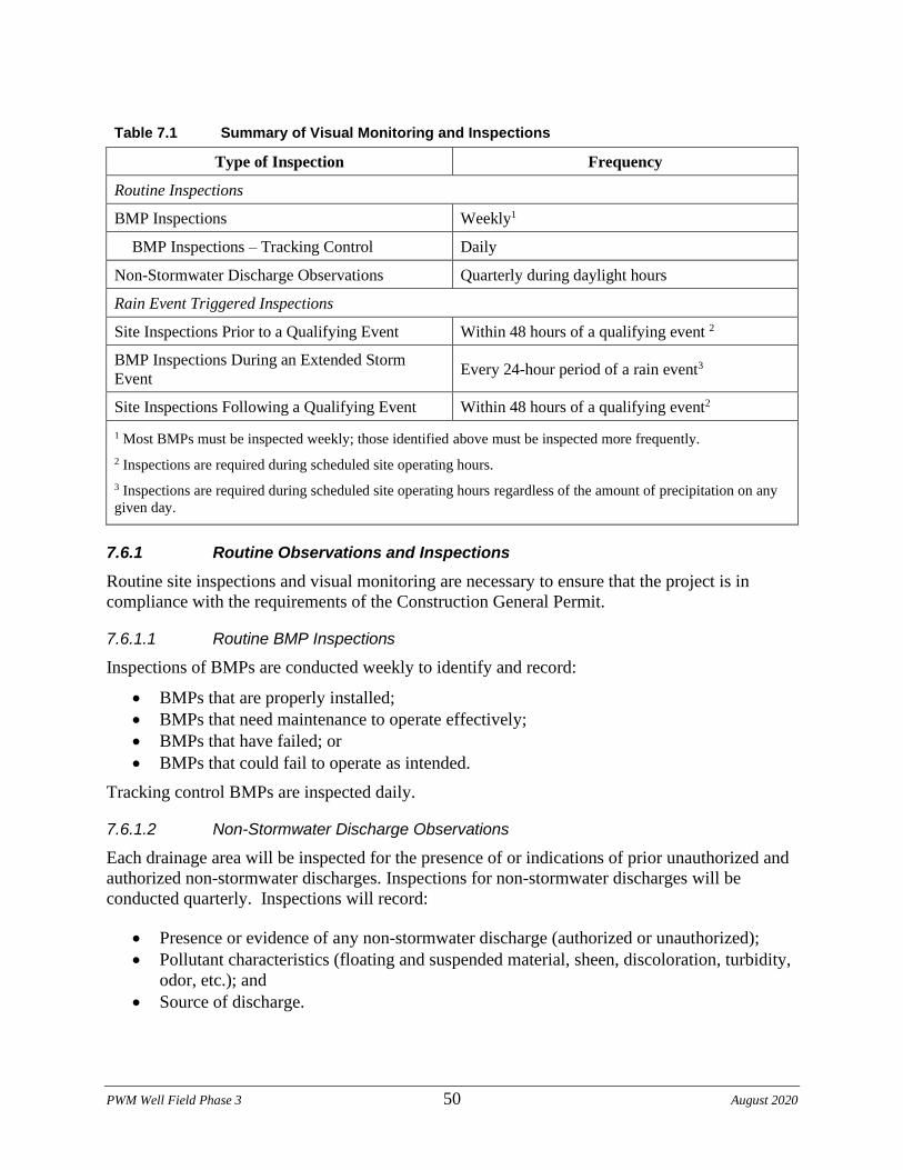
PWM Well Field Phase 3 50 August 2020
Table 7.1 Summary of Visual Monitoring and Inspections
Type of Inspection Frequency
Routine Inspections
BMP Inspections Weekly1
BMP Inspections – Tracking Control Daily
Non-Stormwater Discharge Observations Quarterly during daylight hours
Rain Event Triggered Inspections
Site Inspections Prior to a Qualifying Event Within 48 hours of a qualifying event 2
BMP Inspections During an Extended Storm
Event Every 24-hour period of a rain event3
Site Inspections Following a Qualifying Event Within 48 hours of a qualifying event2
1 Most BMPs must be inspected weekly; those identified above must be inspected more frequently.
2 Inspections are required during scheduled site operating hours.
3 Inspections are required during scheduled site operating hours regardless of the amount of precipitation on any
given day.
7.6.1 Routine Observations and Inspections
Routine site inspections and visual monitoring are necessary to ensure that the project is in
compliance with the requirements of the Construction General Permit.
7.6.1.1 Routine BMP Inspections
Inspections of BMPs are conducted weekly to identify and record:
• BMPs that are properly installed;
• BMPs that need maintenance to operate effectively;
• BMPs that have failed; or
• BMPs that could fail to operate as intended.
Tracking control BMPs are inspected daily.
7.6.1.2 Non-Stormwater Discharge Observations
Each drainage area will be inspected for the presence of or indications of prior unauthorized and
authorized non-stormwater discharges. Inspections for non-stormwater discharges will be
conducted quarterly. Inspections will record:
• Presence or evidence of any non-stormwater discharge (authorized or unauthorized);
• Pollutant characteristics (floating and suspended material, sheen, discoloration, turbidity,
odor, etc.); and
• Source of discharge.
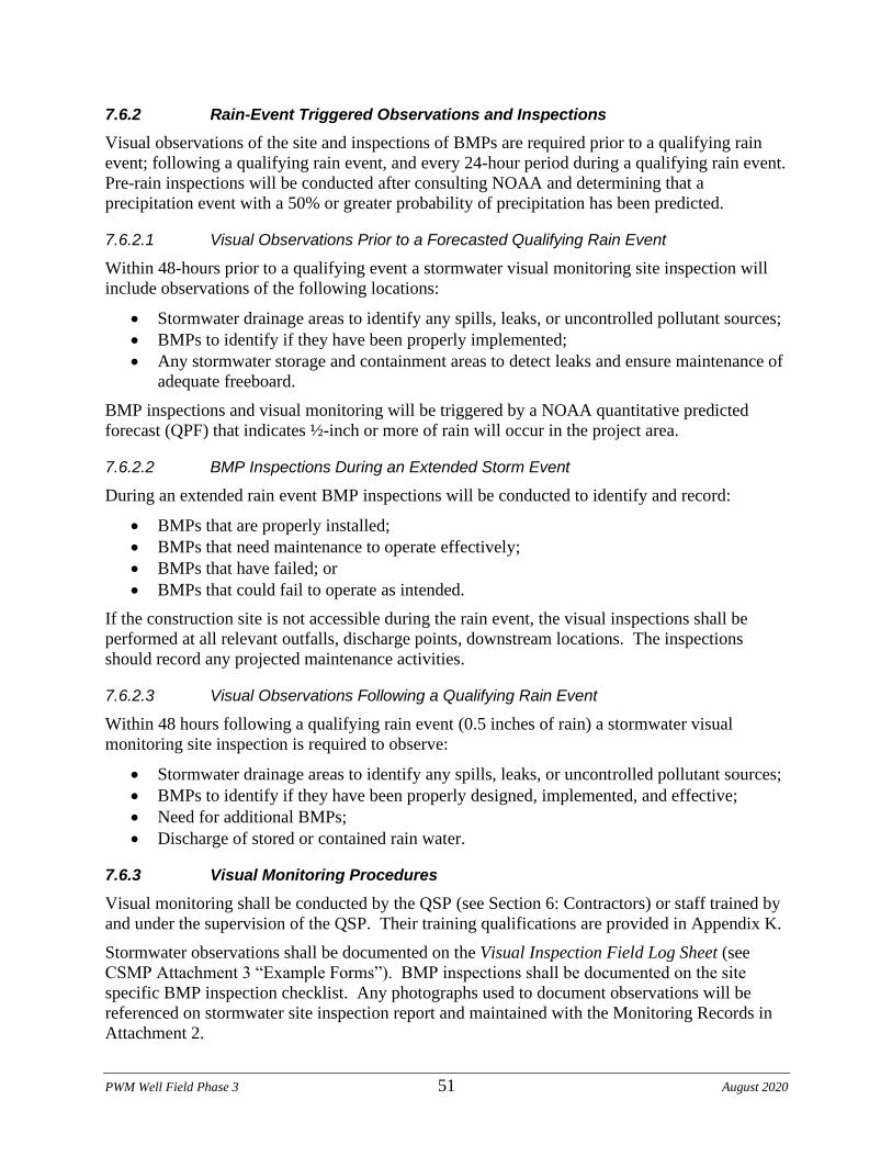
PWM Well Field Phase 3 51 August 2020
7.6.2 Rain-Event Triggered Observations and Inspections
Visual observations of the site and inspections of BMPs are required prior to a qualifying rain
event; following a qualifying rain event, and every 24-hour period during a qualifying rain event.
Pre-rain inspections will be conducted after consulting NOAA and determining that a
precipitation event with a 50% or greater probability of precipitation has been predicted.
7.6.2.1 Visual Observations Prior to a Forecasted Qualifying Rain Event
Within 48-hours prior to a qualifying event a stormwater visual monitoring site inspection will
include observations of the following locations:
• Stormwater drainage areas to identify any spills, leaks, or uncontrolled pollutant sources;
• BMPs to identify if they have been properly implemented;
• Any stormwater storage and containment areas to detect leaks and ensure maintenance of
adequate freeboard.
BMP inspections and visual monitoring will be triggered by a NOAA quantitative predicted
forecast (QPF) that indicates ½-inch or more of rain will occur in the project area.
7.6.2.2 BMP Inspections During an Extended Storm Event
During an extended rain event BMP inspections will be conducted to identify and record:
• BMPs that are properly installed;
• BMPs that need maintenance to operate effectively;
• BMPs that have failed; or
• BMPs that could fail to operate as intended.
If the construction site is not accessible during the rain event, the visual inspections shall be
performed at all relevant outfalls, discharge points, downstream locations. The inspections
should record any projected maintenance activities.
7.6.2.3 Visual Observations Following a Qualifying Rain Event
Within 48 hours following a qualifying rain event (0.5 inches of rain) a stormwater visual
monitoring site inspection is required to observe:
• Stormwater drainage areas to identify any spills, leaks, or uncontrolled pollutant sources;
• BMPs to identify if they have been properly designed, implemented, and effective;
• Need for additional BMPs;
• Discharge of stored or contained rain water.
7.6.3 Visual Monitoring Procedures
Visual monitoring shall be conducted by the QSP (see Section 6: Contractors) or staff trained by
and under the supervision of the QSP. Their training qualifications are provided in Appendix K.
Stormwater observations shall be documented on the Visual Inspection Field Log Sheet (see
CSMP Attachment 3 “Example Forms”). BMP inspections shall be documented on the site
specific BMP inspection checklist. Any photographs used to document observations will be
referenced on stormwater site inspection report and maintained with the Monitoring Records in
Attachment 2.
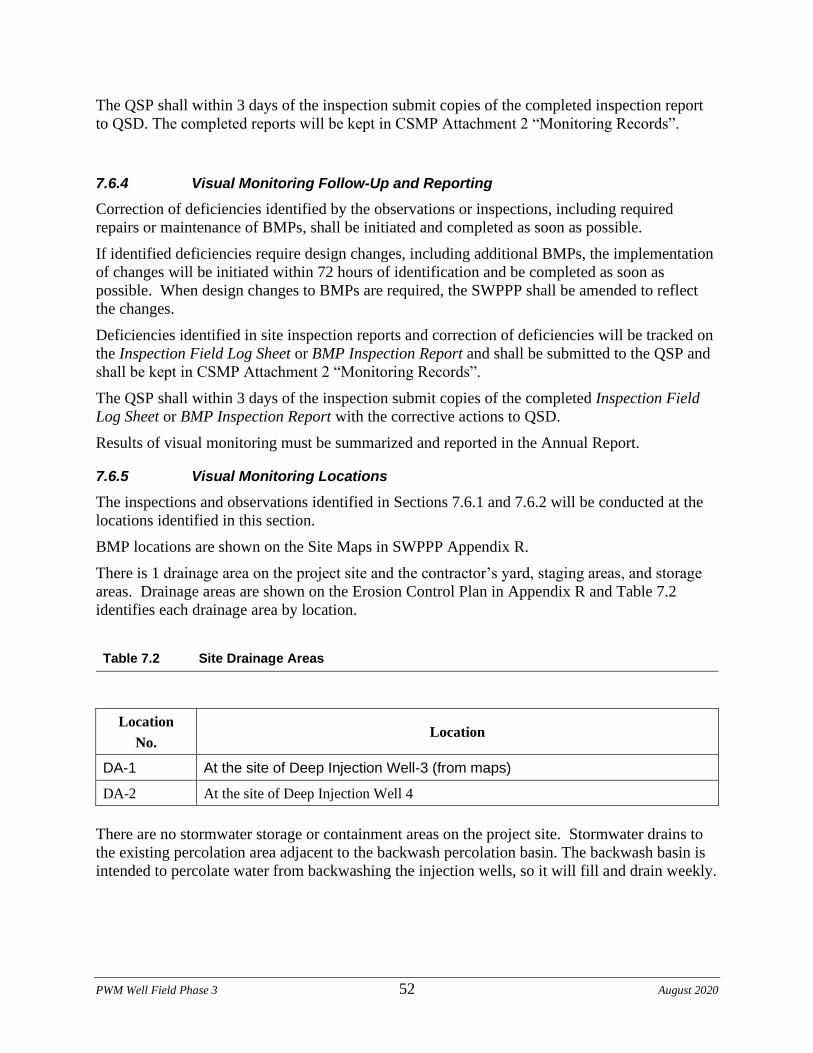
PWM Well Field Phase 3 52 August 2020
The QSP shall within 3 days of the inspection submit copies of the completed inspection report
to QSD. The completed reports will be kept in CSMP Attachment 2 “Monitoring Records”.
7.6.4 Visual Monitoring Follow-Up and Reporting
Correction of deficiencies identified by the observations or inspections, including required
repairs or maintenance of BMPs, shall be initiated and completed as soon as possible.
If identified deficiencies require design changes, including additional BMPs, the implementation
of changes will be initiated within 72 hours of identification and be completed as soon as
possible. When design changes to BMPs are required, the SWPPP shall be amended to reflect
the changes.
Deficiencies identified in site inspection reports and correction of deficiencies will be tracked on
the Inspection Field Log Sheet or BMP Inspection Report and shall be submitted to the QSP and
shall be kept in CSMP Attachment 2 “Monitoring Records”.
The QSP shall within 3 days of the inspection submit copies of the completed Inspection Field
Log Sheet or BMP Inspection Report with the corrective actions to QSD.
Results of visual monitoring must be summarized and reported in the Annual Report.
7.6.5 Visual Monitoring Locations
The inspections and observations identified in Sections 7.6.1 and 7.6.2 will be conducted at the
locations identified in this section.
BMP locations are shown on the Site Maps in SWPPP Appendix R.
There is 1 drainage area on the project site and the contractor’s yard, staging areas, and storage
areas. Drainage areas are shown on the Erosion Control Plan in Appendix R and Table 7.2
identifies each drainage area by location.
Table 7.2 Site Drainage Areas
Location
No. Location
DA-1 At the site of Deep Injection Well-3 (from maps)
DA-2 At the site of Deep Injection Well 4
There are no stormwater storage or containment areas on the project site. Stormwater drains to
the existing percolation area adjacent to the backwash percolation basin. The backwash basin is
intended to percolate water from backwashing the injection wells, so it will fill and drain weekly.
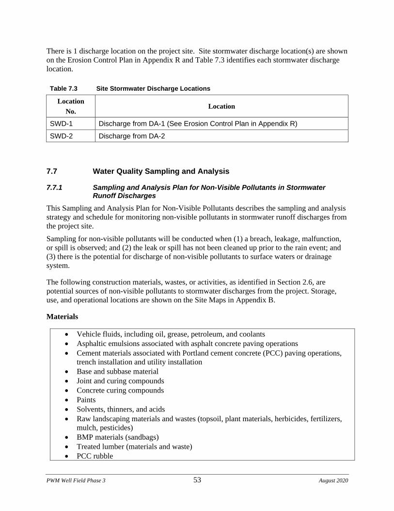
PWM Well Field Phase 3 53 August 2020
There is 1 discharge location on the project site. Site stormwater discharge location(s) are shown
on the Erosion Control Plan in Appendix R and Table 7.3 identifies each stormwater discharge
location.
Table 7.3 Site Stormwater Discharge Locations
Location
No. Location
SWD-1 Discharge from DA-1 (See Erosion Control Plan in Appendix R)
SWD-2 Discharge from DA-2
7.7 Water Quality Sampling and Analysis
7.7.1 Sampling and Analysis Plan for Non-Visible Pollutants in Stormwater Runoff Discharges
This Sampling and Analysis Plan for Non-Visible Pollutants describes the sampling and analysis
strategy and schedule for monitoring non-visible pollutants in stormwater runoff discharges from
the project site.
Sampling for non-visible pollutants will be conducted when (1) a breach, leakage, malfunction,
or spill is observed; and (2) the leak or spill has not been cleaned up prior to the rain event; and
(3) there is the potential for discharge of non-visible pollutants to surface waters or drainage
system.
The following construction materials, wastes, or activities, as identified in Section 2.6, are
potential sources of non-visible pollutants to stormwater discharges from the project. Storage,
use, and operational locations are shown on the Site Maps in Appendix B.
Materials
• Vehicle fluids, including oil, grease, petroleum, and coolants
• Asphaltic emulsions associated with asphalt concrete paving operations
• Cement materials associated with Portland cement concrete (PCC) paving operations,
trench installation and utility installation
• Base and subbase material
• Joint and curing compounds
• Concrete curing compounds
• Paints
• Solvents, thinners, and acids
• Raw landscaping materials and wastes (topsoil, plant materials, herbicides, fertilizers,
mulch, pesticides)
• BMP materials (sandbags)
• Treated lumber (materials and waste)
• PCC rubble
PWM Well Field Phase 3 54 August 2020
General litter
Activities
• Clearing and grubing operations
• Grading operations
• Utility excavation operations
• Well drilling and development operations
• Landscaping operations
• Painting
There are NO existing site features that may be potential sources of non-visible pollutants to
stormwater discharges from the project.
No soil amendments that have the potential to change the chemical properties, engineering
properties, or erosion resistance of the soil will be used on the project site.
PWM Well Field Phase 3 55 August 2020
7.7.1.1 Sampling Schedule
Samples for the potential non-visible pollutant(s) and a sufficiently large unaffected background
sample shall be collected during the first two hours of discharge from rain events that result in a
sufficient discharge for sample collection. Samples shall be collected during the site’s scheduled
hours and shall be collected regardless of the time of year and phase of the construction.
Collection of discharge samples for non-visible pollutant monitoring will be triggered when any
of the following conditions are observed during site inspections conducted prior to or during a
rain event.
• Materials or wastes containing potential non-visible pollutants are not stored under
watertight conditions. Watertight conditions are defined as (1) storage in a watertight
container, (2) storage under a watertight roof or within a building, or (3) protected by
temporary cover and containment that prevents stormwater contact and runoff from the
storage area.
• Materials or wastes containing potential non-visible pollutants are stored under watertight
conditions, but (1) a breach, malfunction, leakage, or spill is observed, (2) the leak or
spill is not cleaned up prior to the rain event, and (3) there is the potential for discharge of
non-visible pollutants to surface waters or a storm drain system.
• A construction activity, including but not limited to those in Section 2.6, with the
potential to contribute non-visible pollutants (1) was occurring during or within 24 hours
prior to the rain event, (2) BMPs were observed to be breached, malfunctioning, or
improperly implemented, and (3) there is the potential for discharge of non-visible
pollutants to surface waters or a storm drain system.
• Soil amendments that have the potential to change the chemical properties, engineering
properties, or erosion resistance of the soil have been applied, and there is the potential
for discharge of non-visible pollutants to surface waters or a storm drain system.
• Stormwater runoff from an area contaminated by historical usage of the site has been
observed to combine with stormwater runoff from the site, and there is the potential for
discharge of non-visible pollutants to surface waters or a storm drain system.
7.7.1.2 Sampling Locations
Sampling locations are based on proximity to planned non-visible pollutant storage, occurrence
or use; accessibility for sampling, and personnel safety. Planned non-visible pollutant sampling
locations are shown on the Erosion Control Plan in Appendix R and include the locations
identified in Tables 7.4 through 7.5.
One sampling location each on the project site and the contractor’s yard have been identified for
the collection of samples of runoff from planned material and waste storage areas and areas
where non-visible pollutant producing construction activities are planned.
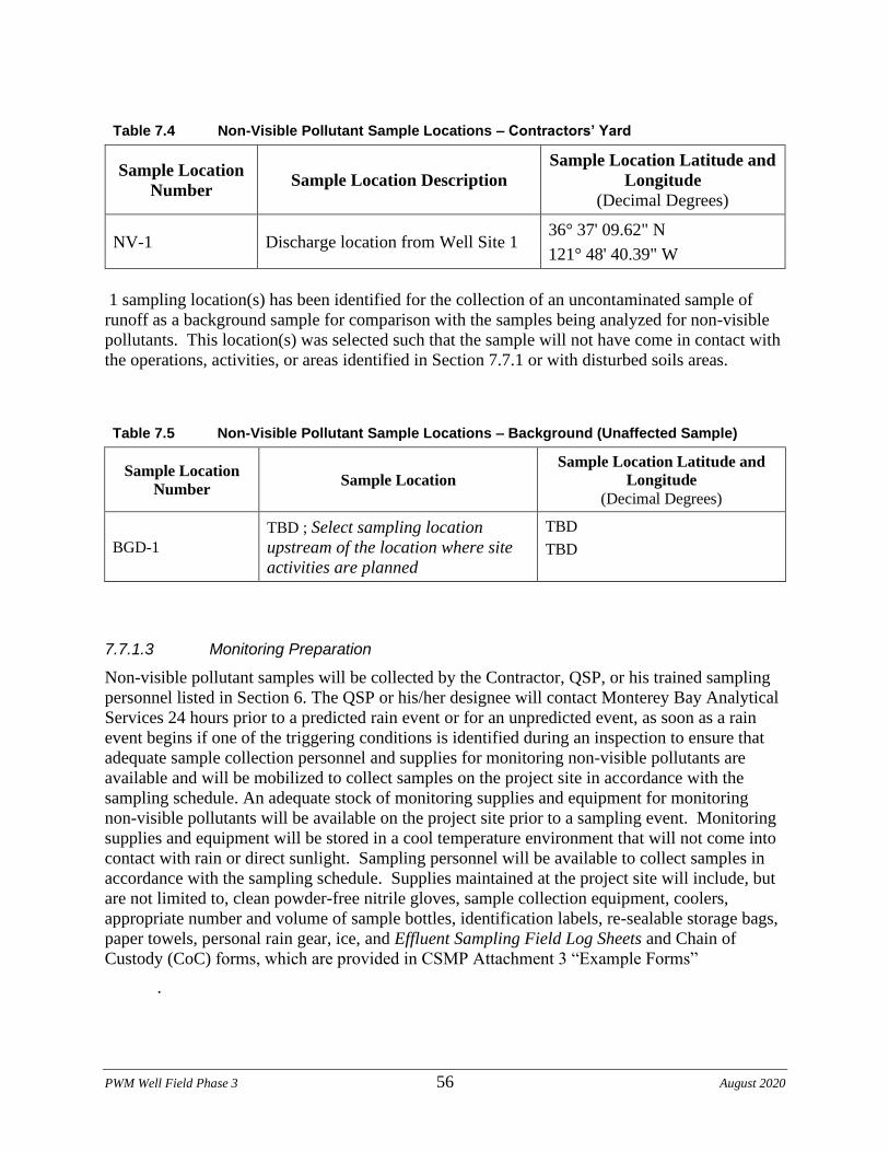
PWM Well Field Phase 3 56 August 2020
Table 7.4 Non-Visible Pollutant Sample Locations – Contractors’ Yard
Sample Location
Number Sample Location Description
Sample Location Latitude and
Longitude
(Decimal Degrees)
NV-1 Discharge location from Well Site 1 36° 37' 09.62" N
121° 48' 40.39" W
1 sampling location(s) has been identified for the collection of an uncontaminated sample of
runoff as a background sample for comparison with the samples being analyzed for non-visible
pollutants. This location(s) was selected such that the sample will not have come in contact with
the operations, activities, or areas identified in Section 7.7.1 or with disturbed soils areas.
Table 7.5 Non-Visible Pollutant Sample Locations – Background (Unaffected Sample)
Sample Location
Number Sample Location
Sample Location Latitude and
Longitude
(Decimal Degrees)
BGD-1
TBD ; Select sampling location
upstream of the location where site
activities are planned
TBD
TBD
7.7.1.3 Monitoring Preparation
Non-visible pollutant samples will be collected by the Contractor, QSP, or his trained sampling
personnel listed in Section 6. The QSP or his/her designee will contact Monterey Bay Analytical
Services 24 hours prior to a predicted rain event or for an unpredicted event, as soon as a rain
event begins if one of the triggering conditions is identified during an inspection to ensure that
adequate sample collection personnel and supplies for monitoring non-visible pollutants are
available and will be mobilized to collect samples on the project site in accordance with the
sampling schedule. An adequate stock of monitoring supplies and equipment for monitoring
non-visible pollutants will be available on the project site prior to a sampling event. Monitoring
supplies and equipment will be stored in a cool temperature environment that will not come into
contact with rain or direct sunlight. Sampling personnel will be available to collect samples in
accordance with the sampling schedule. Supplies maintained at the project site will include, but
are not limited to, clean powder-free nitrile gloves, sample collection equipment, coolers,
appropriate number and volume of sample bottles, identification labels, re-sealable storage bags,
paper towels, personal rain gear, ice, and Effluent Sampling Field Log Sheets and Chain of
Custody (CoC) forms, which are provided in CSMP Attachment 3 “Example Forms”
.
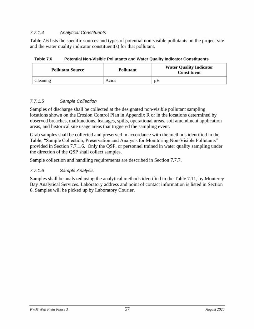
PWM Well Field Phase 3 57 August 2020
7.7.1.4 Analytical Constituents
Table 7.6 lists the specific sources and types of potential non-visible pollutants on the project site
and the water quality indicator constituent(s) for that pollutant.
Table 7.6 Potential Non-Visible Pollutants and Water Quality Indicator Constituents
Pollutant Source Pollutant Water Quality Indicator
Constituent
Cleaning Acids pH
7.7.1.5 Sample Collection
Samples of discharge shall be collected at the designated non-visible pollutant sampling
locations shown on the Erosion Control Plan in Appendix R or in the locations determined by
observed breaches, malfunctions, leakages, spills, operational areas, soil amendment application
areas, and historical site usage areas that triggered the sampling event.
Grab samples shall be collected and preserved in accordance with the methods identified in the
Table, “Sample Collection, Preservation and Analysis for Monitoring Non-Visible Pollutants”
provided in Section 7.7.1.6. Only the QSP, or personnel trained in water quality sampling under
the direction of the QSP shall collect samples.
Sample collection and handling requirements are described in Section 7.7.7.
7.7.1.6 Sample Analysis
Samples shall be analyzed using the analytical methods identified in the Table 7.11, by Monterey
Bay Analytical Services. Laboratory address and point of contact information is listed in Section
6. Samples will be picked up by Laboratory Courier.
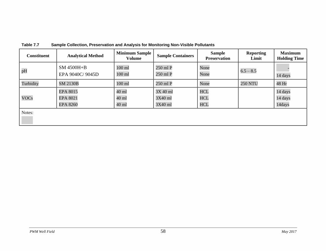
PWM Well Field 58 May 2017
Table 7.7 Sample Collection, Preservation and Analysis for Monitoring Non-Visible Pollutants
Constituent Analytical Method Minimum Sample
Volume Sample Containers
Sample
Preservation
Reporting
Limit
Maximum
Holding Time
pH SM 4500H+B
EPA 9040C/ 9045D
100 ml
100 ml
250 ml P
250 ml P
None
None 6.5 – 8.5
-
14 days
Turbidity SM 2130B 100 ml 250 ml P None 250 NTU 48 Hr
VOCs
EPA 8015
EPA 8021
EPA 8260
40 ml
40 ml
40 ml
3X 40 ml
3X40 ml
3X40 ml
HCL
HCL
HCL
14 days
14 days
14days
Notes:
PWM Well Field Phase 3 59 August 2020
7.7.1.7 Data Evaluation and Reporting
The QSP shall complete an evaluation of the water quality sample analytical results.
Runoff/downgradient results shall be compared with the associated upgradient/unaffected results
and any associated run-on results. Should the runoff/downgradient sample show an increased
level of the tested analyte relative to the unaffected background sample, which cannot be
explained by run-on results, the BMPs, site conditions, and surrounding influences shall be
assessed to determine the probable cause for the increase.
As determined by the site and data evaluation, appropriate BMPs shall be repaired or modified to
mitigate discharges of non-visible pollutant concentrations. Any revisions to the BMPs shall be
recorded as an amendment to the SWPPP.
The General Permit prohibits the storm water discharges that contain hazardous substances equal
to or in excess of reportable quantities established in 40 C.F.R. §§ 117.3 and 302.4. The results
of any non-stormwater discharge results that indicate the presence of a hazardous substance in
excess of established reportable quantities shall be immediately reported to the Regional Water
Board and other agencies as required by 40 C.F.R. §§ 117.3 and 302.4.
Results of non-visible pollutant monitoring shall be reported in the Annual Report.
7.7.2 Sampling and Analysis Plan for pH and Turbidity in Stormwater Runoff Discharges
Sampling and analysis of runoff for pH and turbidity is not required for Risk Level 1 projects
unless one of the aforementioned sampling triggers occurs.
7.7.3 Sampling and Analysis Plan for pH, Turbidity, and SSC in Receiving Water
This project is not subject to Receiving Water Monitoring.
7.7.3.1 Sampling Schedule and Locations
This project is not subject to Receiving Water Monitoring.
7.7.4 Sampling and Analysis Plan for Non-Stormwater Discharges
This project is not subject to the non-stormwater sampling and analysis requirements of the
General Permit because it is a Risk Level 1 project, unless triggered by above criteria.
PWM Well Field 60 May 2017
PWM Well Field Phase 3 61 August 2020
7.7.5 Sampling and Analysis Plan for Other Pollutants Required by the Regional Water Board
The Regional Water Board has not specified monitoring for additional pollutants.
7.7.6 Training of Sampling Personnel
Sampling personnel shall be trained to collect, maintain, and ship samples in accordance with the
Surface Water Ambient Monitoring program (SWAMP) 2008 Quality Assurance Program Plan
(QAPrP). Training records of designated contractor sampling personnel are provided in
Appendix K.
The stormwater sampler(s) and alternate(s) have received the following stormwater sampling
training: TBD
Name Training
INSERT LIST OF TRAINING COURSES
INSERT LIST OF TRAINING COURSES
The stormwater sampler(s) and alternates have the following stormwater sampling experience:
Name Experience
INSERT LIST OF STORMWATER SAMPLING EXPERIENCE
INSERT LIST OF STORMWATER SAMPLING EXPERIENCE
7.7.7 Sample Collection and Handling
7.7.7.1 Sample Collection
Samples shall be collected at the designated sampling locations shown on the Site Maps and
listed in the preceding sections. Samples shall be collected, maintained and shipped in
accordance with the SWAMP 2008 Quality Assurance Program Plan (QAPrP).
Grab samples shall be collected and preserved in accordance with the methods identified in
preceding sections.
To maintain sample integrity and prevent cross-contamination, sample collection personnel shall
follow the protocols below.
• Collect samples (for laboratory analysis) only in analytical laboratory-provided sample
containers;
• Wear clean, powder-free nitrile gloves when collecting samples;
• Change gloves whenever something not known to be clean has been touched;
• Change gloves between sites;
• Decontaminate all equipment (e.g. bucket, tubing) prior to sample collection using a
trisodium phosphate water wash, distilled water rinse, and final rinse with distilled water.
(Dispose of wash and rinse water appropriately, i.e., do not discharge to storm drain or
receiving water). Do not decontaminate laboratory provided sample containers;
PWM Well Field Phase 3 62 August 2020
• Do not smoke during sampling events;
• Never sample near a running vehicle;
• Do not park vehicles in the immediate sample collection area (even non-running
vehicles);
• Do not eat or drink during sample collection; and
• Do not breathe, sneeze, or cough in the direction of an open sample container.
The most important aspect of grab sampling is to collect a sample that represents the entire
runoff stream. Typically, samples are collected by dipping the collection container in the runoff
flow paths and streams as noted below.
i. For small streams and flow paths, simply dip the bottle facing upstream until full.
ii. For larger stream that can be safely accessed, collect a sample in the middle of the flow
stream by directly dipping the mouth of the bottle. Once again making sure that the
opening of the bottle is facing upstream as to avoid any contamination by the sampler.
iii. For larger streams that cannot be safely waded, pole-samplers may be needed to safely
access the representative flow.
iv. Avoid collecting samples from ponded, sluggish or stagnant water.
v. Avoid collecting samples directly downstream from a bridge as the samples can be
affected by the bridge structure or runoff from the road surface.
Note, that depending upon the specific analytical test, some containers may contain
preservatives. These containers should never be dipped into the stream, but filled indirectly from
the collection container.
7.7.7.2 Sample Handling
Turbidity and pH measurements must be conducted immediately. Do not store turbidity or pH
samples for later measurement.
Samples for laboratory analysis must be handled as follows. Immediately following sample
collection:
• Cap sample containers;
• Complete sample container labels;
• Sealed containers in a re-sealable storage bag;
• Place sample containers into an ice-chilled cooler;
• Document sample information on the Effluent Sampling Field Log Sheet; and
• Complete the CoC.
All samples for laboratory analysis must be maintained between 0-6 degrees Celsius during
delivery to the laboratory. Samples must be kept on ice, or refrigerated, from sample collection
through delivery to the laboratory. Place samples to be shipped inside coolers with ice. Make
sure the sample bottles are well packaged to prevent breakage and secure cooler lids with
packaging tape.
Ship samples that will be laboratory analyzed to the analytical laboratory right away. Hold times
are measured from the time the sample is collected to the time the sample is analyzed. The
General Permit requires that samples be received by the analytical laboratory within 48 hours of
the physical sampling (unless required sooner by the analytical laboratory).
PWM Well Field Phase 3 63 August 2020
7.7.7.3 Sample Documentation Procedures
All original data documented on sample bottle identification labels, Effluent Sampling Field Log
Sheet, and CoCs shall be recorded using waterproof ink. These shall be considered accountable
documents. If an error is made on an accountable document, the individual shall make
corrections by lining through the error and entering the correct information. The erroneous
information shall not be obliterated. All corrections shall be initialed and dated.
Duplicate samples shall be identified consistent with the numbering system for other samples to
prevent the laboratory from identifying duplicate samples. Duplicate samples shall be identified
in the Effluent Sampling Field Log Sheet.
Sample documentation procedures include the following:
Sample Bottle Identification Labels: Sampling personnel shall attach an identification label to
each sample bottle. Sample identification shall uniquely identify each sample location.
Field Log Sheets: Sampling personnel shall complete the Effluent Sampling Field Log Sheet and
Receiving Water Sampling Field Log Sheet for each sampling event, as appropriate.
Chain of Custody: Sampling personnel shall complete the CoC for each sampling event for
which samples are collected for laboratory analysis. The sampler will sign the CoC when the
sample(s) is turned over to the testing laboratory or courier.
7.8 Active Treatment System Monitoring
An Active Treatment System (ATS) will be deployed on the site?
Yes No
This project does not require a project specific Sampling and Analysis Plan for an ATS because
deployment of an ATS is not planned.
7.9 Bioassessment Monitoring
This project is not subject to bioassessment monitoring because it is not a Risk Level 3 project.
7.10 Watershed Monitoring Option
This project is not participating in a watershed monitoring option.
7.11 Quality Assurance and Quality Control
An effective Quality Assurance and Quality Control (QA/QC) plan shall be implemented as part
of the CSMP to ensure that analytical data can be used with confidence. QA/QC procedures to
be initiated include the following:
• Field logs;
• Clean sampling techniques;
• CoCs;
• QA/QC Samples; and
PWM Well Field Phase 3 64 August 2020
• Data verification.
Each of these procedures is discussed in more detail in the following sections.
7.11.1 Field Logs
The purpose of field logs is to record sampling information and field observations during
monitoring that may explain any uncharacteristic analytical results. Sampling information to be
included in the field log include the date and time of water quality sample collection, sampling
personnel, sample container identification numbers, and types of samples that were collected.
Field observations should be noted in the field log for any abnormalities at the sampling location
(color, odor, BMPs, etc.). Field measurements for pH and turbidity should also be recorded in
the field log. A Visual Inspection Field Log, and an Effluent Sampling Field Log Sheet are
included in CSMP Attachment 3 “Example Forms”.
7.11.2 Clean Sampling Techniques
Clean sampling techniques involve the use of certified clean containers for sample collection and
clean powder-free nitrile gloves during sample collection and handling. As discussed in Section
7.7.7, adoption of a clean sampling approach will minimize the chance of field contamination
and questionable data results.
7.11.3 Chain of Custody
The sample CoC is an important documentation step that tracks samples from collection through
analysis to ensure the validity of the sample. Sample CoC procedures include the following:
• Proper labeling of samples;
• Use of CoC forms for all samples; and
• Prompt sample delivery to the analytical laboratory.
Analytical laboratories usually provide CoC forms to be filled out for sample containers. An
example CoC is included in CSMP Attachment 3 “Example Forms”.
7.11.4 QA/QC Samples
QA/QC samples provide an indication of the accuracy and precision of the sample collection;
sample handling; field measurements; and analytical laboratory methods. The following types of
QA/QC will be conducted for this project:
Field Duplicates at a frequency of 1 duplicate minimum per sampling event.
(Required for all sampling plans with field measurements or laboratory analysis)
7.11.4.1 Field Duplicates
Field duplicates provide verification of laboratory or field analysis and sample collection.
Duplicate samples shall be collected, handled, and analyzed using the same protocols as primary
samples. The sample location where field duplicates are collected shall be randomly selected
from the discharge locations. Duplicate samples shall be collected immediately after the primary
sample has been collected. Duplicate samples must be collected in the same manner and as close
in time as possible to the original sample. Duplicate samples shall not influence any evaluations
or conclusion.
PWM Well Field Phase 3 65 August 2020
7.11.4.2 Equipment Blanks
Equipment blanks provide verification that equipment has not introduced a pollutant into the
sample. Equipment blanks are typically collected when:
• New equipment is used;
• Equipment that has been cleaned after use at a contaminated site;
• Equipment that is not dedicated for surface water sampling is used; or
• Whenever a new lot of filters is used when sampling metals.
7.11.4.3 Field Blanks
Field blanks assess potential sample contamination levels that occur during field sampling
activities. De-ionized water field blanks are taken to the field, transferred to the appropriate
container, and treated the same as the corresponding sample type during the course of a sampling
event.
7.11.4.4 Travel Blanks
Travel blanks assess the potential for cross-contamination of volatile constituents between
sample containers during shipment from the field to the laboratory. De-ionized water blanks are
taken along for the trip and held unopened in the same cooler with the VOC samples.
7.11.5 Data Verification
After results are received from the analytical laboratory, the QSP shall verify the data to ensure
that it is complete, accurate, and the appropriate QA/QC requirements were met. Data must be
verified as soon as the data reports are received. Data verification shall include:
• Check the CoC and laboratory reports.
Make sure all requested analyses were performed and all samples are accounted for in
the reports.
• Check laboratory reports to make sure hold times were met and that the reporting levels
meet or are lower than the reporting levels agreed to in the contract.
• Check data for outlier values and follow up with the laboratory.
Occasionally typographical errors, unit reporting errors, or incomplete results are
reported and should be easily detected. These errors need to be identified, clarified, and
corrected quickly by the laboratory. The QSP should especially note data that is an
order of magnitude or more different than similar locations, or is inconsistent with
previous data from the same location.
• Check laboratory QA/QC results.
EPA establishes QA/QC checks and acceptable criteria for laboratory analyses. These
data are typically reported along with the sample results. The QSP shall evaluate the
reported QA/QC data to check for contamination (method, field, and equipment blanks),
precision (laboratory matrix spike duplicates), and accuracy (matrix spikes and
laboratory control samples). When QA/QC checks are outside acceptable ranges, the
laboratory must flag the data, and usually provides an explanation of the potential
impact to the sample results.
• Check the data set for outlier values and, accordingly, confirm results and re-analyze
samples where appropriate.
PWM Well Field Phase 3 66 August 2020
Sample re-analysis should only be undertaken when it appears that some part of the
QA/QC resulted in a value out of the accepted range. Sample results may not be
discounted unless the analytical laboratory identifies the required QA/QC criteria were
not met and confirms this in writing.
Field data including inspections and observations must be verified as soon as the field logs are
received, typically at the end of the sampling event. Field data verification shall include:
• Check field logs to make sure all required measurements were completed and
appropriately documented;
• Check reported values that appear out of the typical range or inconsistent;
Follow-up immediately to identify potential reporting or equipment problems, if
appropriate, recalibrate equipment after sampling;
• Verify equipment calibrations;
• Review observations noted on the field logs; and
• Review notations of any errors and actions taken to correct the equipment or recording
errors.
7.12 Records Retention
All records of stormwater monitoring information and copies of reports (including Annual
Reports) must be retained for a period of at least three years from date of submittal or longer if
required by the Regional Water Board.
Results of visual monitoring, field measurements, and laboratory analyses must be kept in the
SWPPP along with CoCs, and other documentation related to the monitoring.
Records are to be kept onsite while construction is ongoing. Records to be retained include:
• The date, place, and time of inspections, sampling, visual observations, and/or
measurements, including precipitation;
• The individual(s) who performed the inspections, sampling, visual observation, and/or
field measurements;
• The date and approximate time of field measurements and laboratory analyses;
• The individual(s) who performed the laboratory analyses;
• A summary of all analytical results, the method detection limits and reporting limits, and
the analytical techniques or methods used;
• Rain gauge readings from site inspections;
• QA/QC records and results;
• Calibration records;
• Visual observation and sample collection exemption records;
• The records of any corrective actions and follow-up activities that resulted from
analytical results, visual observations, or inspections; and
• NAL Exceedance Reports.
PWM Well Field Phase 3 67 August 2020
CSMP Attachment 1: Weather Reports

PWM Well Field Phase 3 68 August 2020
PWM Well Field Phase 3 69 August 2020
CSMP Attachment 2: Monitoring Records

PWM Well Field Phase 3 70 August 2020
PWM Well Field Phase 3 71 August 2020
CSMP Attachment 3: Example Forms

PWM Well Field Phase 3 72 August 2020

PWM Well Field Phase 3 73 August 2020
Rain Gauge Log Sheet
Construction Site Name:
WDID #:
Date (mm/dd/yy)
Time (24-hr) Initials Rainfall Depth
(Inches) Notes:
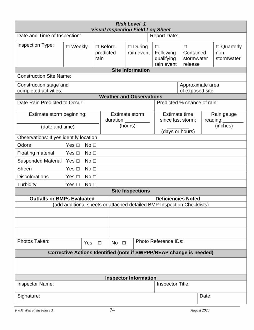
PWM Well Field Phase 3 74 August 2020
Risk Level 1 Visual Inspection Field Log Sheet
Date and Time of Inspection: Report Date:
Inspection Type: □ Weekly □ Before predicted rain
□ During rain event
□ Following qualifying rain event
□ Contained stormwater release
□ Quarterly non-stormwater
Site Information
Construction Site Name:
Construction stage and completed activities:
Approximate area of exposed site:
Weather and Observations
Date Rain Predicted to Occur: Predicted % chance of rain:
Estimate storm beginning:
(date and time)
Estimate storm duration:_________
(hours)
Estimate time since last storm:
________ (days or hours)
Rain gauge reading: _______
(inches)
Observations: If yes identify location Odors Yes □ No □ Floating material Yes □ No □ Suspended Material Yes □ No □ Sheen Yes □ No □ Discolorations Yes □ No □ Turbidity Yes □ No □
Site Inspections
Outfalls or BMPs Evaluated Deficiencies Noted
(add additional sheets or attached detailed BMP Inspection Checklists)
Photos Taken: Yes □ No □ Photo Reference IDs:
Corrective Actions Identified (note if SWPPP/REAP change is needed)
Inspector Information
Inspector Name: Inspector Title:
Signature: Date:

PWM Well Field Phase 3 75 August 2020

PWM Well Field Phase 3 76 August 2020

PWM Well Field Phase 3 77 August 2020
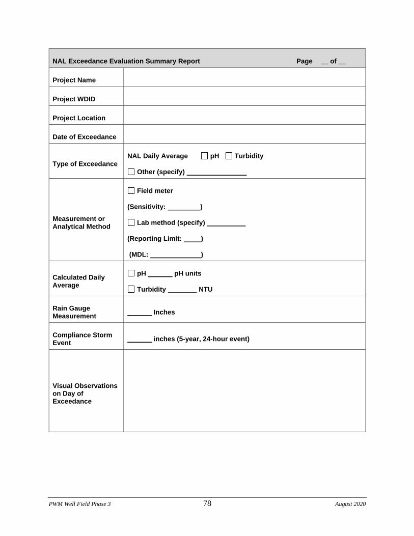
PWM Well Field Phase 3 78 August 2020
NAL Exceedance Evaluation Summary Report Page __ of __
Project Name
Project WDID
Project Location
Date of Exceedance
Type of Exceedance
NAL Daily Average pH Turbidity
Other (specify)
Measurement or Analytical Method
Field meter
(Sensitivity: )
Lab method (specify)
(Reporting Limit: )
(MDL: )
Calculated Daily Average
pH pH units
Turbidity NTU
Rain Gauge Measurement
Inches
Compliance Storm Event
inches (5-year, 24-hour event)
Visual Observations on Day of Exceedance
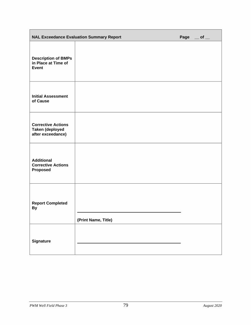
PWM Well Field Phase 3 79 August 2020
NAL Exceedance Evaluation Summary Report Page __ of __
Description of BMPs in Place at Time of Event
Initial Assessment of Cause
Corrective Actions Taken (deployed after exceedance)
Additional Corrective Actions Proposed
Report Completed By
(Print Name, Title)
Signature
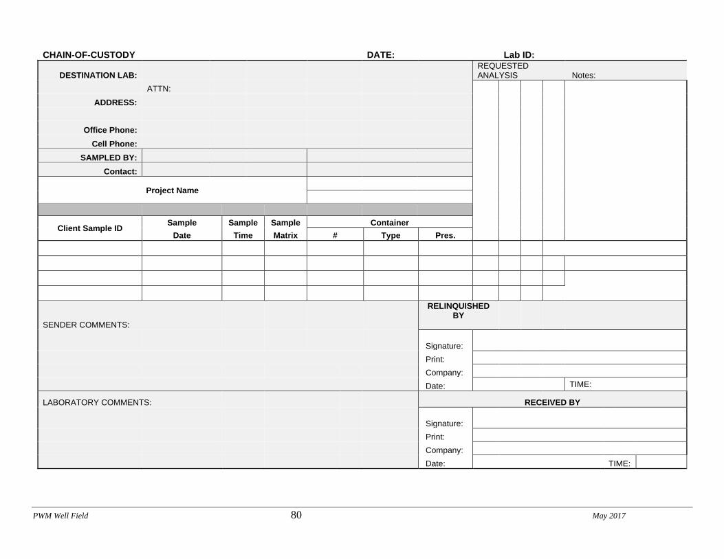
PWM Well Field 80 May 2017
CHAIN-OF-CUSTODY DATE: Lab ID:
DESTINATION LAB: REQUESTED ANALYSIS Notes:
ATTN:
ADDRESS:
Office Phone:
Cell Phone:
SAMPLED BY:
Contact:
Project Name
Client Sample ID Sample Sample Sample Container
Date Time Matrix # Type Pres.
SENDER COMMENTS:
RELINQUISHED BY
Signature: Print: Company: Date: TIME:
LABORATORY COMMENTS: RECEIVED BY
Signature: Print: Company: Date: TIME:
PWM Well Field 81 May 2017
CSMP Attachment 4: Field Meter Instructions

PWM Well Field 82 May 2017
PWM Well Field 83 May 2017
CSMP Attachment 5: Supplemental Information

PWM Well Field 84 May 2017
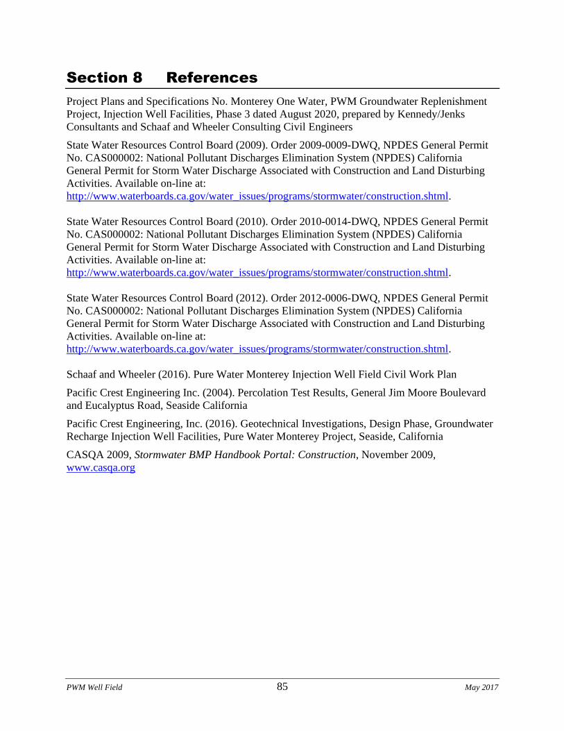
PWM Well Field 85 May 2017
Section 8 References
Project Plans and Specifications No. Monterey One Water, PWM Groundwater Replenishment
Project, Injection Well Facilities, Phase 3 dated August 2020, prepared by Kennedy/Jenks
Consultants and Schaaf and Wheeler Consulting Civil Engineers
State Water Resources Control Board (2009). Order 2009-0009-DWQ, NPDES General Permit
No. CAS000002: National Pollutant Discharges Elimination System (NPDES) California
General Permit for Storm Water Discharge Associated with Construction and Land Disturbing
Activities. Available on-line at:
http://www.waterboards.ca.gov/water_issues/programs/stormwater/construction.shtml.
State Water Resources Control Board (2010). Order 2010-0014-DWQ, NPDES General Permit
No. CAS000002: National Pollutant Discharges Elimination System (NPDES) California
General Permit for Storm Water Discharge Associated with Construction and Land Disturbing
Activities. Available on-line at:
http://www.waterboards.ca.gov/water_issues/programs/stormwater/construction.shtml.
State Water Resources Control Board (2012). Order 2012-0006-DWQ, NPDES General Permit
No. CAS000002: National Pollutant Discharges Elimination System (NPDES) California
General Permit for Storm Water Discharge Associated with Construction and Land Disturbing
Activities. Available on-line at:
http://www.waterboards.ca.gov/water_issues/programs/stormwater/construction.shtml.
Schaaf and Wheeler (2016). Pure Water Monterey Injection Well Field Civil Work Plan
Pacific Crest Engineering Inc. (2004). Percolation Test Results, General Jim Moore Boulevard
and Eucalyptus Road, Seaside California
Pacific Crest Engineering, Inc. (2016). Geotechnical Investigations, Design Phase, Groundwater
Recharge Injection Well Facilities, Pure Water Monterey Project, Seaside, California
CASQA 2009, Stormwater BMP Handbook Portal: Construction, November 2009,
www.casqa.org

PWM Well Field Phase 3 86 August 2020
Appendix A: Calculations

PWM Well Field Phase 3 87 August 2020
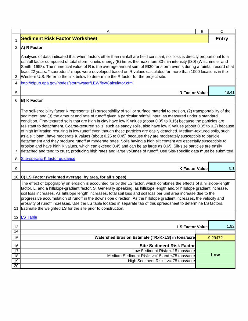
1
2
34
5
6
7
8
9
10
11
12
131415
1617181920
A B C
Entry
48.41
0.1
1.92
Watershed Erosion Estimate (=RxKxLS) in tons/acre
Site Sediment Risk FactorLow Sediment Risk: < 15 tons/acre
Medium Sediment Risk: >=15 and <75 tons/acreHigh Sediment Risk: >= 75 tons/acre
Sediment Risk Factor Worksheet
A) R Factor
R Factor Value
B) K Factor
Analyses of data indicated that when factors other than rainfall are held constant, soil loss is directly proportional to a rainfall factor composed of total storm kinetic energy (E) times the maximum 30-min intensity (I30) (Wischmeier and Smith, 1958). The numerical value of R is the average annual sum of EI30 for storm events during a rainfall record of at least 22 years. "Isoerodent" maps were developed based on R values calculated for more than 1000 locations in the Western U.S. Refer to the link below to determine the R factor for the project site.http://cfpub.epa.gov/npdes/stormwater/LEW/lewCalculator.cfm
K Factor Value
LS Factor Value
Low
C) LS Factor (weighted average, by area, for all slopes)
The soil-erodibility factor K represents: (1) susceptibility of soil or surface material to erosion, (2) transportability of the sediment, and (3) the amount and rate of runoff given a particular rainfall input, as measured under a standard condition. Fine-textured soils that are high in clay have low K values (about 0.05 to 0.15) because the particles are resistant to detachment. Coarse-textured soils, such as sandy soils, also have low K values (about 0.05 to 0.2) because of high infiltration resulting in low runoff even though these particles are easily detached. Medium-textured soils, such as a silt loam, have moderate K values (about 0.25 to 0.45) because they are moderately susceptible to particle detachment and they produce runoff at moderate rates. Soils having a high silt content are especially susceptible to erosion and have high K values, which can exceed 0.45 and can be as large as 0.65. Silt-size particles are easily detached and tend to crust, producing high rates and large volumes of runoff. Use Site-specific data must be submitted.
The effect of topography on erosion is accounted for by the LS factor, which combines the effects of a hillslope-length factor, L, and a hillslope-gradient factor, S. Generally speaking, as hillslope length and/or hillslope gradient increase, soil loss increases. As hillslope length increases, total soil loss and soil loss per unit area increase due to the progressive accumulation of runoff in the downslope direction. As the hillslope gradient increases, the velocity and erosivity of runoff increases. Use the LS table located in separate tab of this spreadsheet to determine LS factors. Estimate the weighted LS for the site prior to construction.
9.29472
Site-specific K factor guidance
LS Table
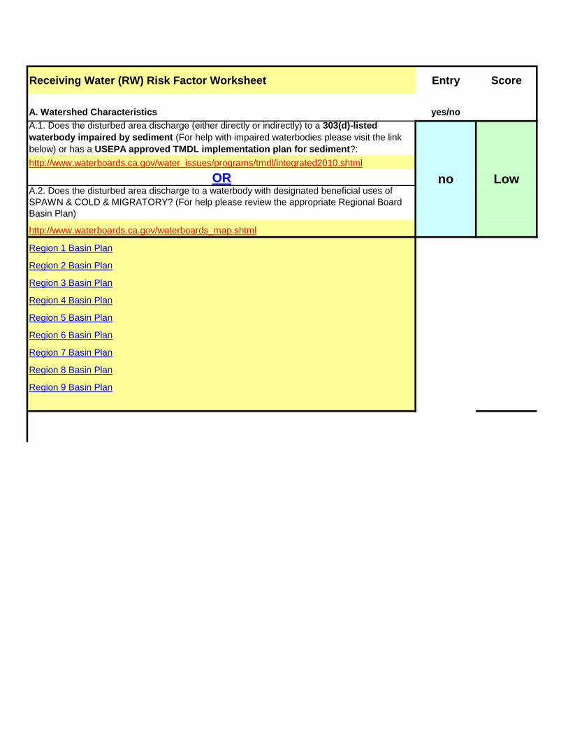
Receiving Water (RW) Risk Factor Worksheet Entry Score
A. Watershed Characteristics yes/no
A.1. Does the disturbed area discharge (either directly or indirectly) to a 303(d)-listed
waterbody impaired by sediment (For help with impaired waterbodies please visit the link below) or has a USEPA approved TMDL implementation plan for sediment?:http://www.waterboards.ca.gov/water_issues/programs/tmdl/integrated2010.shtml
ORA.2. Does the disturbed area discharge to a waterbody with designated beneficial uses of SPAWN & COLD & MIGRATORY? (For help please review the appropriate Regional Board Basin Plan)
http://www.waterboards.ca.gov/waterboards_map.shtml
Region 1 Basin Plan
Region 2 Basin Plan
Region 3 Basin Plan
Region 4 Basin Plan
Region 5 Basin Plan
Region 6 Basin Plan
Region 7 Basin Plan
Region 8 Basin Plan
Region 9 Basin Plan
no Low
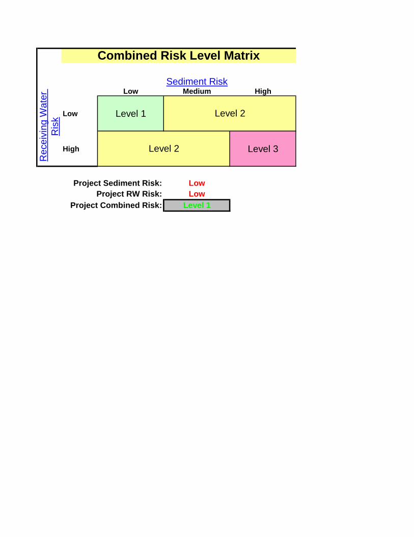
Low Medium High
Low Level 1
High Level 3
Project Sediment Risk: Low 1Project RW Risk: Low 1
Project Combined Risk: Level 1
Combined Risk Level Matrix
Sediment Risk
Rec
eivi
ng W
ater
R
isk Level 2
Level 2
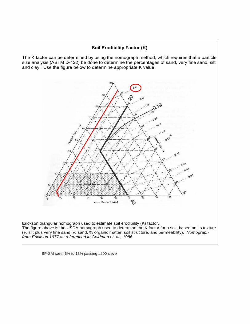
SP-SM soils, 6% to 13% passing #200 sieve
Soil Erodibility Factor (K)
The K factor can be determined by using the nomograph method, which requires that a particle size analysis (ASTM D-422) be done to determine the percentages of sand, very fine sand, silt and clay. Use the figure below to determine appropriate K value.
Erickson triangular nomograph used to estimate soil erodibility (K) factor. The figure above is the USDA nomograph used to determine the K factor for a soil, based on its texture (% silt plus very fine sand, % sand, % organic matter, soil structure, and permeability). Nomograph from Erickson 1977 as referenced in Goldman et. al., 1986.
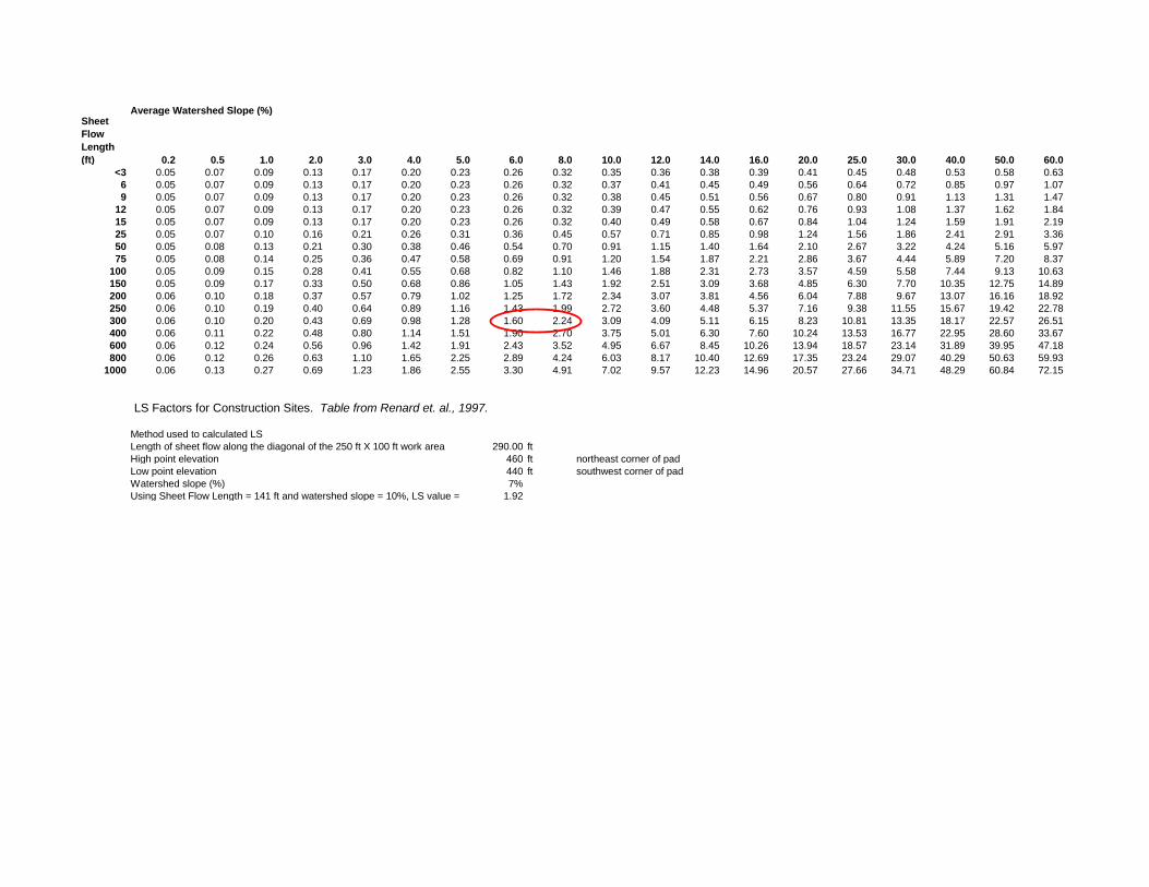
Average Watershed Slope (%)Sheet
Flow
Length
(ft) 0.2 0.5 1.0 2.0 3.0 4.0 5.0 6.0 8.0 10.0 12.0 14.0 16.0 20.0 25.0 30.0 40.0 50.0 60.0
<3 0.05 0.07 0.09 0.13 0.17 0.20 0.23 0.26 0.32 0.35 0.36 0.38 0.39 0.41 0.45 0.48 0.53 0.58 0.636 0.05 0.07 0.09 0.13 0.17 0.20 0.23 0.26 0.32 0.37 0.41 0.45 0.49 0.56 0.64 0.72 0.85 0.97 1.079 0.05 0.07 0.09 0.13 0.17 0.20 0.23 0.26 0.32 0.38 0.45 0.51 0.56 0.67 0.80 0.91 1.13 1.31 1.47
12 0.05 0.07 0.09 0.13 0.17 0.20 0.23 0.26 0.32 0.39 0.47 0.55 0.62 0.76 0.93 1.08 1.37 1.62 1.8415 0.05 0.07 0.09 0.13 0.17 0.20 0.23 0.26 0.32 0.40 0.49 0.58 0.67 0.84 1.04 1.24 1.59 1.91 2.1925 0.05 0.07 0.10 0.16 0.21 0.26 0.31 0.36 0.45 0.57 0.71 0.85 0.98 1.24 1.56 1.86 2.41 2.91 3.3650 0.05 0.08 0.13 0.21 0.30 0.38 0.46 0.54 0.70 0.91 1.15 1.40 1.64 2.10 2.67 3.22 4.24 5.16 5.9775 0.05 0.08 0.14 0.25 0.36 0.47 0.58 0.69 0.91 1.20 1.54 1.87 2.21 2.86 3.67 4.44 5.89 7.20 8.37
100 0.05 0.09 0.15 0.28 0.41 0.55 0.68 0.82 1.10 1.46 1.88 2.31 2.73 3.57 4.59 5.58 7.44 9.13 10.63150 0.05 0.09 0.17 0.33 0.50 0.68 0.86 1.05 1.43 1.92 2.51 3.09 3.68 4.85 6.30 7.70 10.35 12.75 14.89200 0.06 0.10 0.18 0.37 0.57 0.79 1.02 1.25 1.72 2.34 3.07 3.81 4.56 6.04 7.88 9.67 13.07 16.16 18.92250 0.06 0.10 0.19 0.40 0.64 0.89 1.16 1.43 1.99 2.72 3.60 4.48 5.37 7.16 9.38 11.55 15.67 19.42 22.78300 0.06 0.10 0.20 0.43 0.69 0.98 1.28 1.60 2.24 3.09 4.09 5.11 6.15 8.23 10.81 13.35 18.17 22.57 26.51400 0.06 0.11 0.22 0.48 0.80 1.14 1.51 1.90 2.70 3.75 5.01 6.30 7.60 10.24 13.53 16.77 22.95 28.60 33.67600 0.06 0.12 0.24 0.56 0.96 1.42 1.91 2.43 3.52 4.95 6.67 8.45 10.26 13.94 18.57 23.14 31.89 39.95 47.18800 0.06 0.12 0.26 0.63 1.10 1.65 2.25 2.89 4.24 6.03 8.17 10.40 12.69 17.35 23.24 29.07 40.29 50.63 59.93
1000 0.06 0.13 0.27 0.69 1.23 1.86 2.55 3.30 4.91 7.02 9.57 12.23 14.96 20.57 27.66 34.71 48.29 60.84 72.15
LS Factors for Construction Sites. Table from Renard et. al., 1997.
Method used to calculated LSLength of sheet flow along the diagonal of the 250 ft X 100 ft work area 290.00 ftHigh point elevation 460 ft northeast corner of padLow point elevation 440 ft southwest corner of padWatershed slope (%) 7%Using Sheet Flow Length = 141 ft and watershed slope = 10%, LS value = 1.92

National Pollutant Discharge EliminationSystem (NPDES)
CONTACT US
SHARE
Rainfall Erosivity Factor Calculator for SmallConstruction SitesEPA’s stormwater regulations allow NPDES permitting authorities to waive NPDES permitting requirements for stormwaterdischarges from small construction sites if:
the construction site disturbs less than five acres, andthe rainfall erosivity factor (“R” in the revised universal soil loss equation, or RUSLE) value is less than five during the period ofconstruction activity.
If your small construction project is located in an area where EPA is the permitting authority and your R factor is less than five, youqualify for a low erosivity waiver (LEW) from NPDES stormwater permitting. If your small construction project does not qualify for awaiver, then NPDES stormwater permit coverage is required. Follow the steps below to calculate your R-Factor.
LEW certifications are submitted through the NPDES eReporting Tool or “CGP-NeT”. Several states that are authorized to implementthe NPDES permitting program also accept LEWs. Check with your state NPDES permitting authority for more information.
Submit your LEW through EPA’s eReporting ToolList of states, Indian country, and territories where EPA is the permitting authorityConstruction Rainfall Erosivity Waiver Fact SheetAppendix C of the 2017 CGP – Small Construction Waivers and Instructions
The R-factor calculation can also be integrated directly into custom applications using the R-Factor web service.
For questions or comments, email EPA’s CGP staff at [email protected].
Select the estimated start and end dates of construction by clicking the boxes and using the dropdown calendar.
The period of construction activity begins at initial earth disturbance and ends with final stabilization.
Locate your small construction project using the search box below or by clicking on the map.
Location: -121.8156977057751 , 36.61848544608761 Search
1
Start Date: 11/01/2020 End Date: 10/31/2021
2
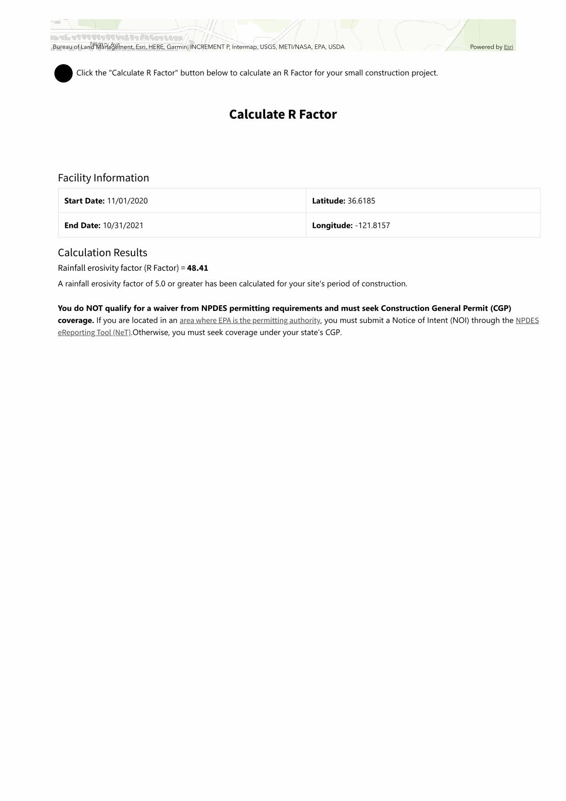
Click the "Calculate R Factor" button below to calculate an R Factor for your small construction project.
Calculate R Factor
Bureau of Land Management, Esri, HERE, Garmin, INCREMENT P, Intermap, USGS, METI/NASA, EPA, USDA Powered by Esri
3
Facility Information
Start Date: 11/01/2020 Latitude: 36.6185
End Date: 10/31/2021 Longitude: -121.8157
Calculation ResultsRainfall erosivity factor (R Factor) = 48.41
A rainfall erosivity factor of 5.0 or greater has been calculated for your site's period of construction.
You do NOT qualify for a waiver from NPDES permitting requirements and must seek Construction General Permit (CGP)coverage. If you are located in an area where EPA is the permitting authority, you must submit a Notice of Intent (NOI) through the NPDESeReporting Tool (NeT).Otherwise, you must seek coverage under your state’s CGP.
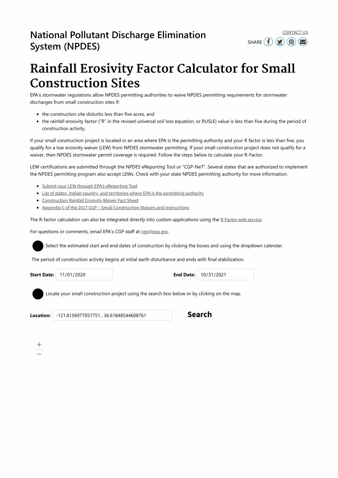

PWM Well Field Phase 3 88 August 2020
Appendix B: Site Maps

PWM Well Field Phase 3 89 August 2020
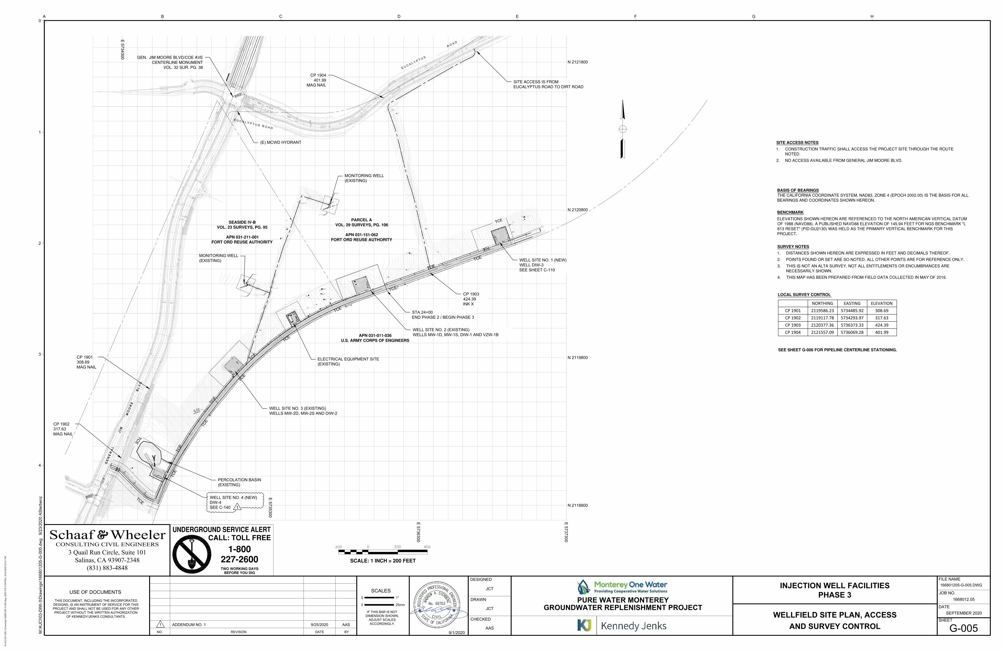
NORTHING EASTING ELEVATIONCP 1901 2119586.23 5734485.92 308.69CP 1902 2119117.78 5734293.97 317.63CP 1903 2120377.36 5736373.33 424.39CP 1904 2121557.09 5736069.28 401.99
4
3
2
1
0
0
USE OF DOCUMENTS
25mm
SCALES
1"
CHECKED
DESIGNED
DRAWN
0
Kennedy/Jenks Consultants
DATE
SHEET
FILE NAME
JOB NO.
D E F G HA B C
IF THIS BAR IS NOT
DIMENSION SHOWN,
ADJUST SCALES
ACCORDINGLY.
THIS DOCUMENT, INCLUDING THE INCORPORATED
DESIGNS, IS AN INSTRUMENT OF SERVICE FOR THIS
PROJECT AND SHALL NOT BE USED FOR ANY OTHER
PROJECT WITHOUT THE WRITTEN AUTHORIZATION
OF KENNEDY/JENKS CONSULTANTS.
NO. REVISION DATE BY
1668012.05
PURE WATER MONTEREY
GROUNDWATER REPLENISHMENT PROJECT
INJECTION WELL FACILITIES
PHASE 3
SEPTEMBER 2020
M:\K
JC
I\0
3-D
IW
-3
\D
ra
win
gs\1
66
80
12
05
-G
-0
05
.d
wg 9
/2
3/2
02
0 A
Ste
rb
en
z
(831) 883-4848Salinas, CA 93907-2348
3 Quail Run Circle, Suite 101
9/1/2020
CP 1903
424.39
INK X
CP 1902
317.63
MAG NAIL
CP 1901
308.69
MAG NAIL
PERCOLATION BASIN
(EXISTING)
WELL SITE NO. 2 (EXISTING)
WELLS MW-1D, MW-1S, DIW-1 AND VZW-1B
(E) MCWD HYDRANT
WELL SITE NO. 4 (NEW)
DIW-4
SEE C-140 1
WELL SITE NO. 3 (EXISTING)
WELLS MW-2D, MW-2S AND DIW-2
ELECTRICAL EQUIPMENT SITE
(EXISTING)
WELL SITE NO. 1 (NEW)
WELL DIW-3
SEE SHEET C-110
MONITORING WELL
(EXISTING)
MONITORING WELL
(EXISTING)
N 2118800
N 2119800
N 2120800
N 2121800
E 5
73
73
00
E 5
73
63
00
E 5
73
53
00
E 5
73
43
00
JCT
JCT
AAS
1 ADDENDUM NO. 1 9/25/2020 AAS
WELLFIELD SITE PLAN, ACCESS
AND SURVEY CONTROL
G-005
166801205-G-005.DWG
STA 24+00
END PHASE 2 / BEGIN PHASE 3
M:\K
JC
I\03-D
IW
-3\D
raw
in
gs\166801205-G
-005.d
wg
, G
005 SITE C
ON
TR
OL, 9/23/2020 6:25:21 P
M
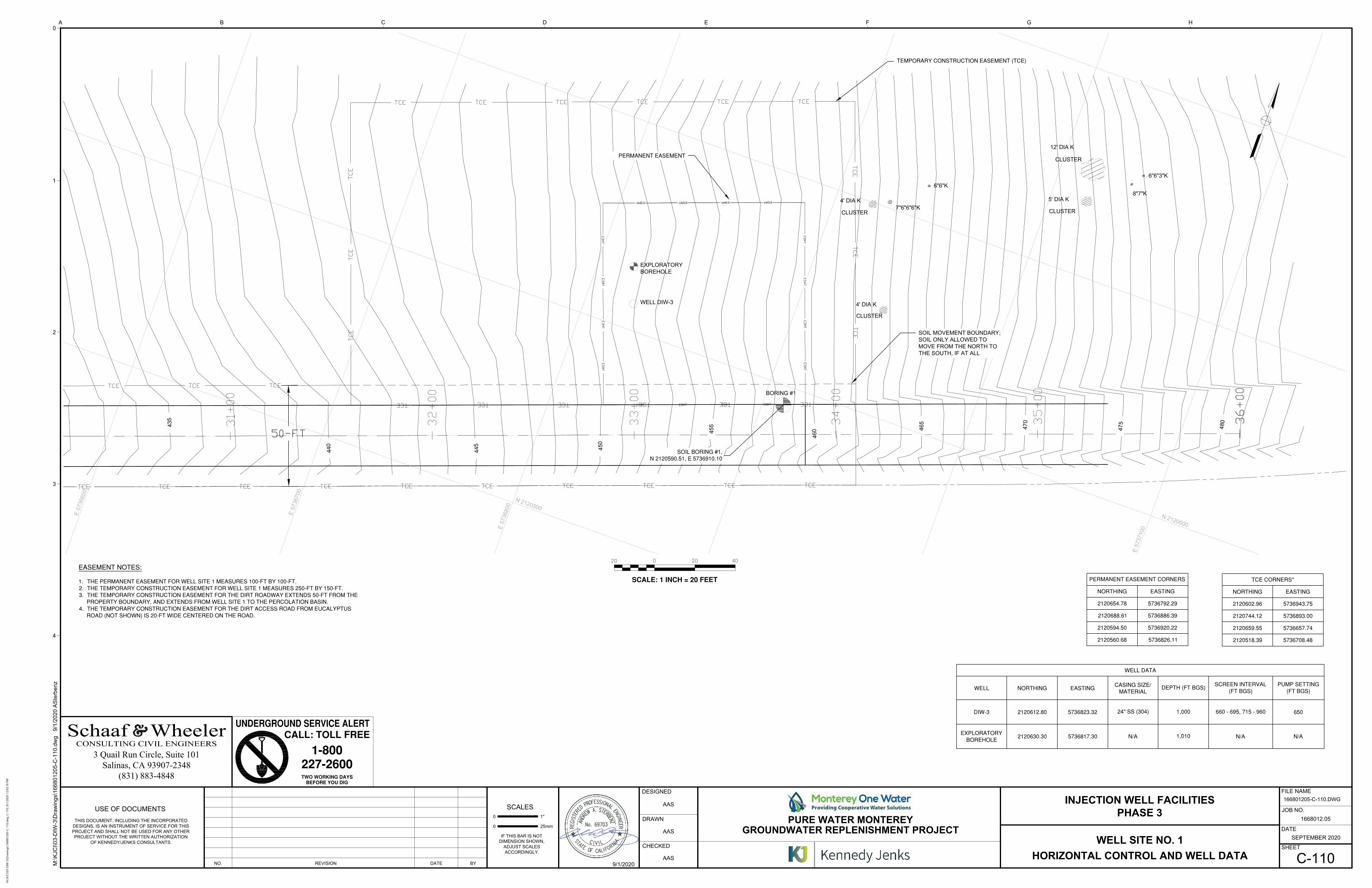
4
3
2
1
0
0
USE OF DOCUMENTS
25mm
SCALES
1"
CHECKED
DESIGNED
DRAWN
0
Kennedy/Jenks Consultants
DATE
SHEET
FILE NAME
JOB NO.
D E F G HA B C
IF THIS BAR IS NOT
DIMENSION SHOWN,
ADJUST SCALES
ACCORDINGLY.
THIS DOCUMENT, INCLUDING THE INCORPORATED
DESIGNS, IS AN INSTRUMENT OF SERVICE FOR THIS
PROJECT AND SHALL NOT BE USED FOR ANY OTHER
PROJECT WITHOUT THE WRITTEN AUTHORIZATION
OF KENNEDY/JENKS CONSULTANTS.
NO. REVISION DATE BY
1668012.05
PURE WATER MONTEREY
GROUNDWATER REPLENISHMENT PROJECT
INJECTION WELL FACILITIES
PHASE 3
SEPTEMBER 2020
M:\K
JC
I\0
3-D
IW
-3
\D
ra
win
gs\1
66
80
12
05
-C
-1
10
.d
wg
9
/1
/2
02
0 A
Ste
rb
en
z
(831) 883-4848Salinas, CA 93907-2348
3 Quail Run Circle, Suite 101
9/1/2020
OIL MOVEMENT BOUNDARY;
SOIL ONLY ALLOWED TO
MOVE FROM THE NORTH TO
THE SOUTH, IF AT ALL
WELL DIW-3
AAS
AAS
AAS
WELL SITE NO. 1
HORIZONTAL CONTROL AND WELL DATA
C-110
166801205-C-110.DWG
EXPLORATORY
BOREHOLE
M:\K
JC
I\03-D
IW
-3\D
raw
in
gs\166801205-C
-110.d
wg
, C
-110, 9/1/2020 12:03:18 P
M
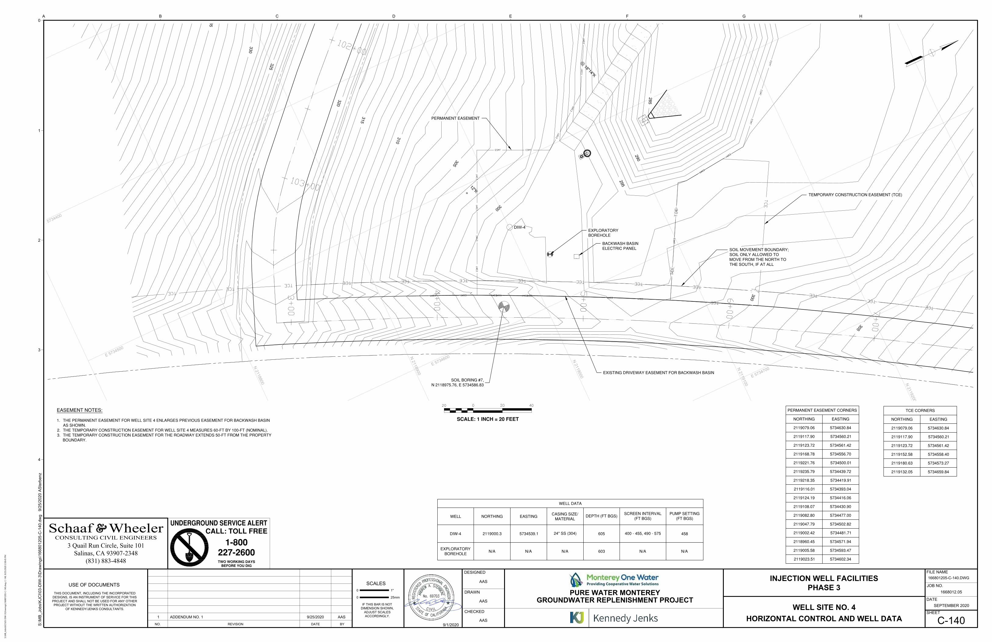
4
3
2
1
0
0
USE OF DOCUMENTS
25mm
SCALES
1"
CHECKED
DESIGNED
DRAWN
0
Kennedy/Jenks Consultants
DATE
SHEET
FILE NAME
JOB NO.
D E F G HA B C
IF THIS BAR IS NOT
DIMENSION SHOWN,
ADJUST SCALES
ACCORDINGLY.
THIS DOCUMENT, INCLUDING THE INCORPORATED
DESIGNS, IS AN INSTRUMENT OF SERVICE FOR THIS
PROJECT AND SHALL NOT BE USED FOR ANY OTHER
PROJECT WITHOUT THE WRITTEN AUTHORIZATION
OF KENNEDY/JENKS CONSULTANTS.
NO. REVISION DATE BY
1668012.05
PURE WATER MONTEREY
GROUNDWATER REPLENISHMENT PROJECT
INJECTION WELL FACILITIES
PHASE 3
SEPTEMBER 2020
S:\M
B_
Jo
bs\K
JC
I\0
3-D
IW
-3
\D
ra
win
gs\1
66
80
12
05
-C
-1
40
.d
wg
9
/2
5/2
02
0 A
Ste
rb
en
z
(831) 883-4848Salinas, CA 93907-2348
3 Quail Run Circle, Suite 101
9/1/2020
OIL MOVEMENT BOUNDARY;
SOIL ONLY ALLOWED TO
MOVE FROM THE NORTH TO
THE SOUTH, IF AT ALL
AAS
AAS
AAS
1 ADDENDUM NO. 1 9/25/2020 AAS
WELL SITE NO. 4
HORIZONTAL CONTROL AND WELL DATA
C-140
166801205-C-140.DWG
S:\M
B_Jo
bs\K
JC
I\03-D
IW
-3\D
raw
in
gs\166801205-C
-140.d
wg
, C
-140, 9/25/2020 3:58:45 P
M
PWM Well Field Phase 3 90 August 2020
Appendix C: Permit Registration Documents
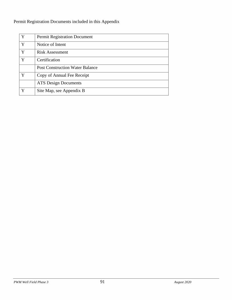
PWM Well Field Phase 3 91 August 2020
Permit Registration Documents included in this Appendix
Y Permit Registration Document
Y Notice of Intent
Y Risk Assessment
Y Certification
Post Construction Water Balance
Y Copy of Annual Fee Receipt
ATS Design Documents
Y Site Map, see Appendix B
PWM Well Field Phase 3 92 August 2020
Appendix D: SWPPP Amendments

PWM Well Field Phase 3 93 August 2020
PWM Well Field Phase 3 94 August 2020
SWPPP Amendment No.
Project Name:
Project Number:
PWM Well Field Phase 3 95 August 2020
Appendix E: Submitted Changes to PRDs
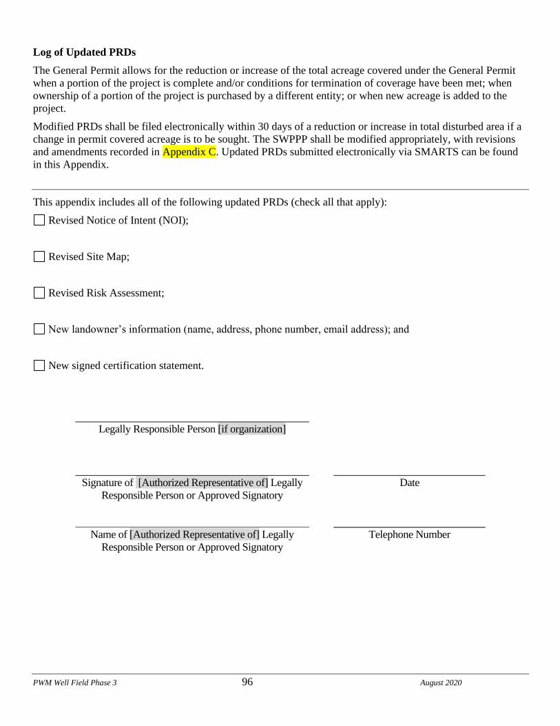
PWM Well Field Phase 3 96 August 2020
Log of Updated PRDs
The General Permit allows for the reduction or increase of the total acreage covered under the General Permit
when a portion of the project is complete and/or conditions for termination of coverage have been met; when
ownership of a portion of the project is purchased by a different entity; or when new acreage is added to the
project.
Modified PRDs shall be filed electronically within 30 days of a reduction or increase in total disturbed area if a
change in permit covered acreage is to be sought. The SWPPP shall be modified appropriately, with revisions
and amendments recorded in Appendix C. Updated PRDs submitted electronically via SMARTS can be found
in this Appendix.
This appendix includes all of the following updated PRDs (check all that apply):
Revised Notice of Intent (NOI);
Revised Site Map;
Revised Risk Assessment;
New landowner’s information (name, address, phone number, email address); and
New signed certification statement.
Legally Responsible Person [if organization]
Signature of [Authorized Representative of] Legally
Responsible Person or Approved Signatory
Date
Name of [Authorized Representative of] Legally
Responsible Person or Approved Signatory
Telephone Number

PWM Well Field Phase 3 97 August 2020
Appendix F: Construction Schedule

PWM Well Field Phase 3 98 August 2020

PWM Well Field Phase 3 99 August 2020
Appendix G: Construction Activities, Materials Used, and
Associated Pollutants

PWM Well Field Phase 3 100 August 2020
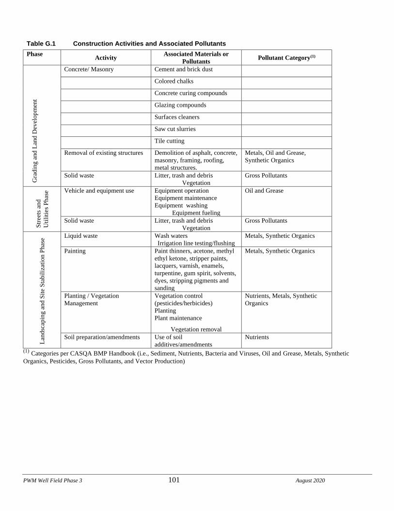
PWM Well Field Phase 3 101 August 2020
Table G.1 Construction Activities and Associated Pollutants
Phase Activity
Associated Materials or
Pollutants Pollutant Category(1)
Gra
din
g a
nd
Lan
d D
evel
op
men
t
Concrete/ Masonry Cement and brick dust
Colored chalks
Concrete curing compounds
Glazing compounds
Surfaces cleaners
Saw cut slurries
Tile cutting
Removal of existing structures Demolition of asphalt, concrete,
masonry, framing, roofing,
metal structures.
Metals, Oil and Grease,
Synthetic Organics
Solid waste Litter, trash and debris
Vegetation
Gross Pollutants
Str
eets
an
d
Uti
liti
es
Ph
ase Vehicle and equipment use Equipment operation
Equipment maintenance
Equipment washing
Equipment fueling
Oil and Grease
Solid waste Litter, trash and debris
Vegetation
Gross Pollutants
Lan
dsc
apin
g a
nd
Sit
e S
tab
iliz
atio
n P
has
e Liquid waste Wash waters
Irrigation line testing/flushing
Metals, Synthetic Organics
Painting Paint thinners, acetone, methyl
ethyl ketone, stripper paints,
lacquers, varnish, enamels,
turpentine, gum spirit, solvents,
dyes, stripping pigments and
sanding
Metals, Synthetic Organics
Planting / Vegetation
Management
Vegetation control
(pesticides/herbicides)
Planting
Plant maintenance
Vegetation removal
Nutrients, Metals, Synthetic
Organics
Soil preparation/amendments Use of soil
additives/amendments
Nutrients
(1) Categories per CASQA BMP Handbook (i.e., Sediment, Nutrients, Bacteria and Viruses, Oil and Grease, Metals, Synthetic
Organics, Pesticides, Gross Pollutants, and Vector Production)
PWM Well Field Phase 3 102 August 2020
Appendix H: CASQA Stormwater BMP Handbook Portal:
Construction Fact Sheets

PWM Well Field Phase 3 103 August 2020
PWM Well Field Phase 3 104 August 2020
Appendix I: BMP Inspection Form

PWM Well Field Phase 3 105 August 2020
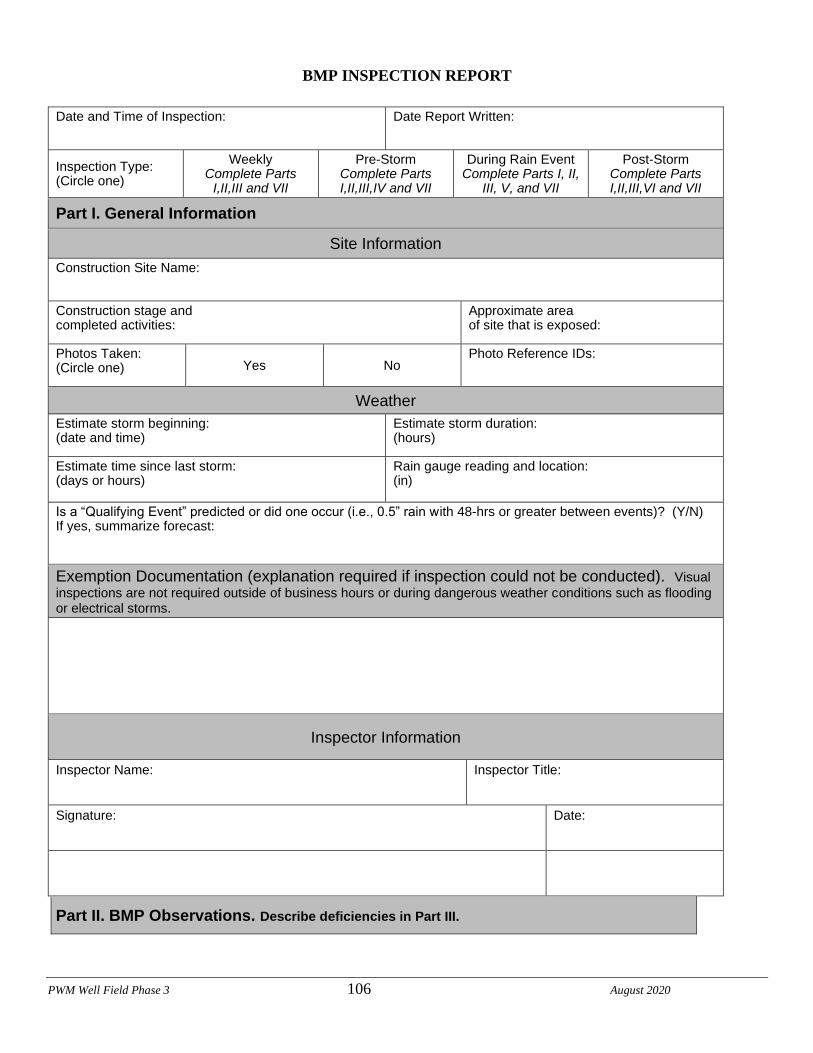
PWM Well Field Phase 3 106 August 2020
BMP INSPECTION REPORT
Date and Time of Inspection: Date Report Written:
Inspection Type: (Circle one)
Weekly Complete Parts
I,II,III and VII
Pre-Storm Complete Parts I,II,III,IV and VII
During Rain Event Complete Parts I, II,
III, V, and VII
Post-Storm Complete Parts I,II,III,VI and VII
Part I. General Information
Site Information Construction Site Name:
Construction stage and completed activities:
Approximate area of site that is exposed:
Photos Taken: (Circle one) Yes No
Photo Reference IDs:
Weather Estimate storm beginning: (date and time)
Estimate storm duration: (hours)
Estimate time since last storm: (days or hours)
Rain gauge reading and location: (in)
Is a “Qualifying Event” predicted or did one occur (i.e., 0.5” rain with 48-hrs or greater between events)? (Y/N) If yes, summarize forecast: Exemption Documentation (explanation required if inspection could not be conducted). Visual inspections are not required outside of business hours or during dangerous weather conditions such as flooding or electrical storms.
Inspector Information
Inspector Name: Inspector Title:
Signature: Date:
Part II. BMP Observations. Describe deficiencies in Part III.
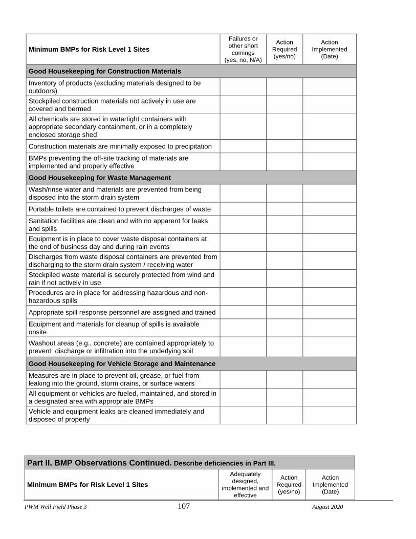
PWM Well Field Phase 3 107 August 2020
Minimum BMPs for Risk Level 1 Sites
Failures or other short comings
(yes, no, N/A)
Action Required (yes/no)
Action Implemented
(Date)
Good Housekeeping for Construction Materials
Inventory of products (excluding materials designed to be outdoors)
Stockpiled construction materials not actively in use are covered and bermed
All chemicals are stored in watertight containers with appropriate secondary containment, or in a completely enclosed storage shed
Construction materials are minimally exposed to precipitation
BMPs preventing the off-site tracking of materials are implemented and properly effective
Good Housekeeping for Waste Management
Wash/rinse water and materials are prevented from being disposed into the storm drain system
Portable toilets are contained to prevent discharges of waste
Sanitation facilities are clean and with no apparent for leaks and spills
Equipment is in place to cover waste disposal containers at the end of business day and during rain events
Discharges from waste disposal containers are prevented from discharging to the storm drain system / receiving water
Stockpiled waste material is securely protected from wind and rain if not actively in use
Procedures are in place for addressing hazardous and non-hazardous spills
Appropriate spill response personnel are assigned and trained
Equipment and materials for cleanup of spills is available onsite
Washout areas (e.g., concrete) are contained appropriately to prevent discharge or infiltration into the underlying soil
Good Housekeeping for Vehicle Storage and Maintenance
Measures are in place to prevent oil, grease, or fuel from leaking into the ground, storm drains, or surface waters
All equipment or vehicles are fueled, maintained, and stored in a designated area with appropriate BMPs
Vehicle and equipment leaks are cleaned immediately and disposed of properly
Part II. BMP Observations Continued. Describe deficiencies in Part III.
Minimum BMPs for Risk Level 1 Sites
Adequately designed,
implemented and effective
Action Required (yes/no)
Action Implemented
(Date)
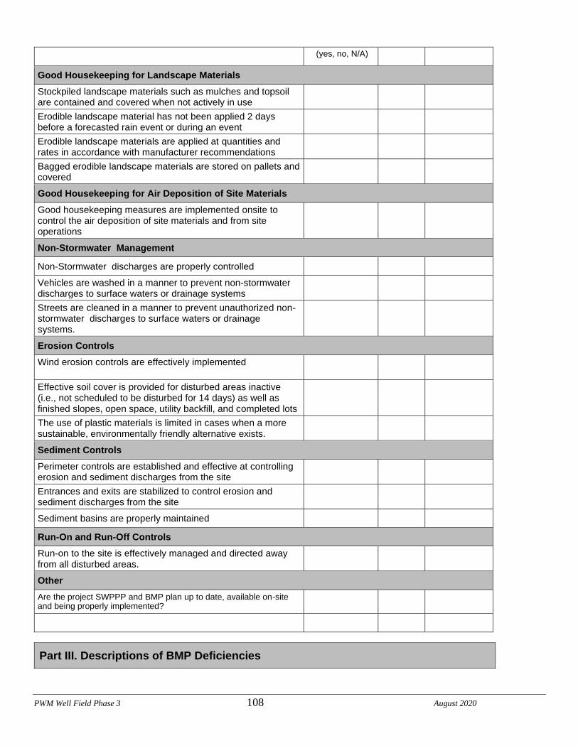
PWM Well Field Phase 3 108 August 2020
(yes, no, N/A)
Good Housekeeping for Landscape Materials
Stockpiled landscape materials such as mulches and topsoil are contained and covered when not actively in use
Erodible landscape material has not been applied 2 days before a forecasted rain event or during an event
Erodible landscape materials are applied at quantities and rates in accordance with manufacturer recommendations
Bagged erodible landscape materials are stored on pallets and covered
Good Housekeeping for Air Deposition of Site Materials
Good housekeeping measures are implemented onsite to control the air deposition of site materials and from site operations
Non-Stormwater Management
Non-Stormwater discharges are properly controlled
Vehicles are washed in a manner to prevent non-stormwater discharges to surface waters or drainage systems
Streets are cleaned in a manner to prevent unauthorized non-stormwater discharges to surface waters or drainage systems.
Erosion Controls
Wind erosion controls are effectively implemented
Effective soil cover is provided for disturbed areas inactive (i.e., not scheduled to be disturbed for 14 days) as well as finished slopes, open space, utility backfill, and completed lots
The use of plastic materials is limited in cases when a more sustainable, environmentally friendly alternative exists.
Sediment Controls
Perimeter controls are established and effective at controlling erosion and sediment discharges from the site
Entrances and exits are stabilized to control erosion and sediment discharges from the site
Sediment basins are properly maintained
Run-On and Run-Off Controls
Run-on to the site is effectively managed and directed away from all disturbed areas.
Other Are the project SWPPP and BMP plan up to date, available on-site and being properly implemented?
Part III. Descriptions of BMP Deficiencies
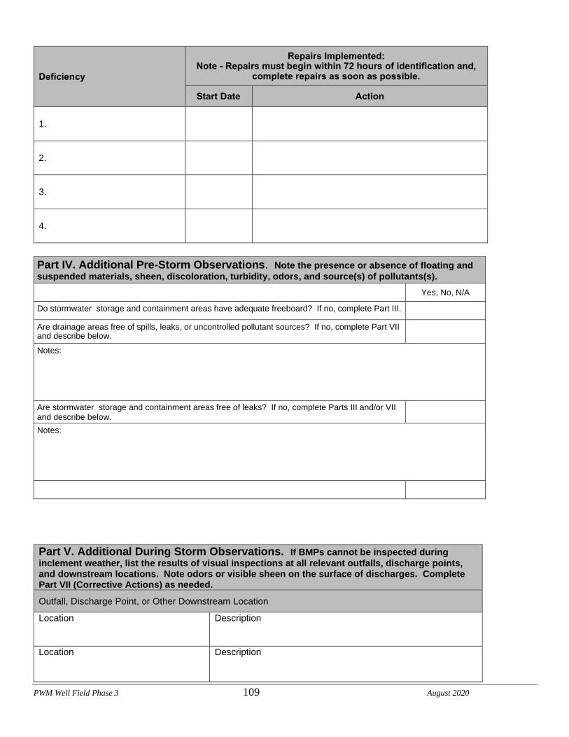
PWM Well Field Phase 3 109 August 2020
Deficiency
Repairs Implemented: Note - Repairs must begin within 72 hours of identification and,
complete repairs as soon as possible.
Start Date Action
1.
2.
3.
4.
Part IV. Additional Pre-Storm Observations. Note the presence or absence of floating and
suspended materials, sheen, discoloration, turbidity, odors, and source(s) of pollutants(s). Yes, No, N/A
Do stormwater storage and containment areas have adequate freeboard? If no, complete Part III. Are drainage areas free of spills, leaks, or uncontrolled pollutant sources? If no, complete Part VII and describe below.
Notes: Are stormwater storage and containment areas free of leaks? If no, complete Parts III and/or VII and describe below.
Notes:
Part V. Additional During Storm Observations. If BMPs cannot be inspected during
inclement weather, list the results of visual inspections at all relevant outfalls, discharge points, and downstream locations. Note odors or visible sheen on the surface of discharges. Complete Part VII (Corrective Actions) as needed.
Outfall, Discharge Point, or Other Downstream Location
Location Description
Location Description
PWM Well Field Phase 3 110 August 2020
Location Description
Location Description
Location Description
Location Description
Location Description
Location Description
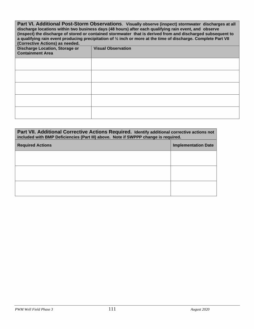
PWM Well Field Phase 3 111 August 2020
Part VI. Additional Post-Storm Observations. Visually observe (inspect) stormwater discharges at all
discharge locations within two business days (48 hours) after each qualifying rain event, and observe (inspect) the discharge of stored or contained stormwater that is derived from and discharged subsequent to a qualifying rain event producing precipitation of ½ inch or more at the time of discharge. Complete Part VII (Corrective Actions) as needed.
Discharge Location, Storage or Containment Area
Visual Observation
Part VII. Additional Corrective Actions Required. Identify additional corrective actions not
included with BMP Deficiencies (Part III) above. Note if SWPPP change is required.
Required Actions Implementation Date
PWM Well Field Phase 3 112 August 2020
Appendix J: Project Specific Rain Event Action Plan
Template

PWM Well Field Phase 3 113 August 2020
NOT APPLICABLE

PWM Well Field Phase 3 114 August 2020
Appendix K: Training Reporting Form

PWM Well Field Phase 3 115 August 2020
Trained Contractor Personnel Log Stormwater Management Training Log and Documentation
Project Name:
WDID #:
Stormwater Management Topic: (check as appropriate)
Erosion Control Sediment Control
Wind Erosion Control Tracking Control
Non-Stormwater Management Waste Management and Materials Pollution Control
Stormwater Sampling
Specific Training Objective:
Location: Date: _
Instructor: Telephone:
Course Length (hours):
Attendee Roster (Attach additional forms if necessary)
Name Company Phone
As needed, add proof of external training (e.g., course completion certificates, credentials for
QSP, QSD).

PWM Well Field Phase 3 116 August 2020
Appendix L: Responsible Parties

PWM Well Field Phase 3 117 August 2020
OPTIONAL
Authorization of Approved Signatories
Project Name:
WDID #:
Name of
Personnel
Project Role Company Signature Date
____________________________ ______________________________
LRP’s Signature Date
____________________________ ______________________________
LRP Name and Title Telephone Number

PWM Well Field Phase 3 118 August 2020
Identification of QSP
Project Name:
WDID #:
The following are QSPs associated with this project
Name of Personnel(1) Company Date
(1) If additional QSPs are required on the job site add additional lines and include information here

PWM Well Field Phase 3 119 August 2020
Authorization of Data Submitters
Project Name:
WDID #:
Name of
Personnel
Project Role Company Signature Date
___________________________ ______________________________
Approved Signatory’s Signature Date
____________________________ ______________________________
Approved Signatory Telephone Number
Name and Title

PWM Well Field Phase 3 120 August 2020
Appendix M: Contractors and Subcontractors
PWM Well Field Phase 3 121 August 2020
Appendix N: Construction General Permit

PWM Well Field Phase 3 122 August 2020
INSTRUCTIONS
• Include a copy of the General Permit, or reference permanent location of General Permit
that is kept on the construction site.
PWM Well Field Phase 3 123 August 2020
Appendix O: Retention of Records / Construction
Records
PWM Well Field Phase 3 124 August 2020
Appendix P: Agency Approvals and Miscellaneous
Documents
PWM Well Field Phase 3 125 August 2020
Appendix Q: Test Methods, Detection Limits,
Reporting Units, Applicable NALs and
NELs
PWM Well Field Phase 3 126 August 2020
Appendix R: Erosion Control Plans
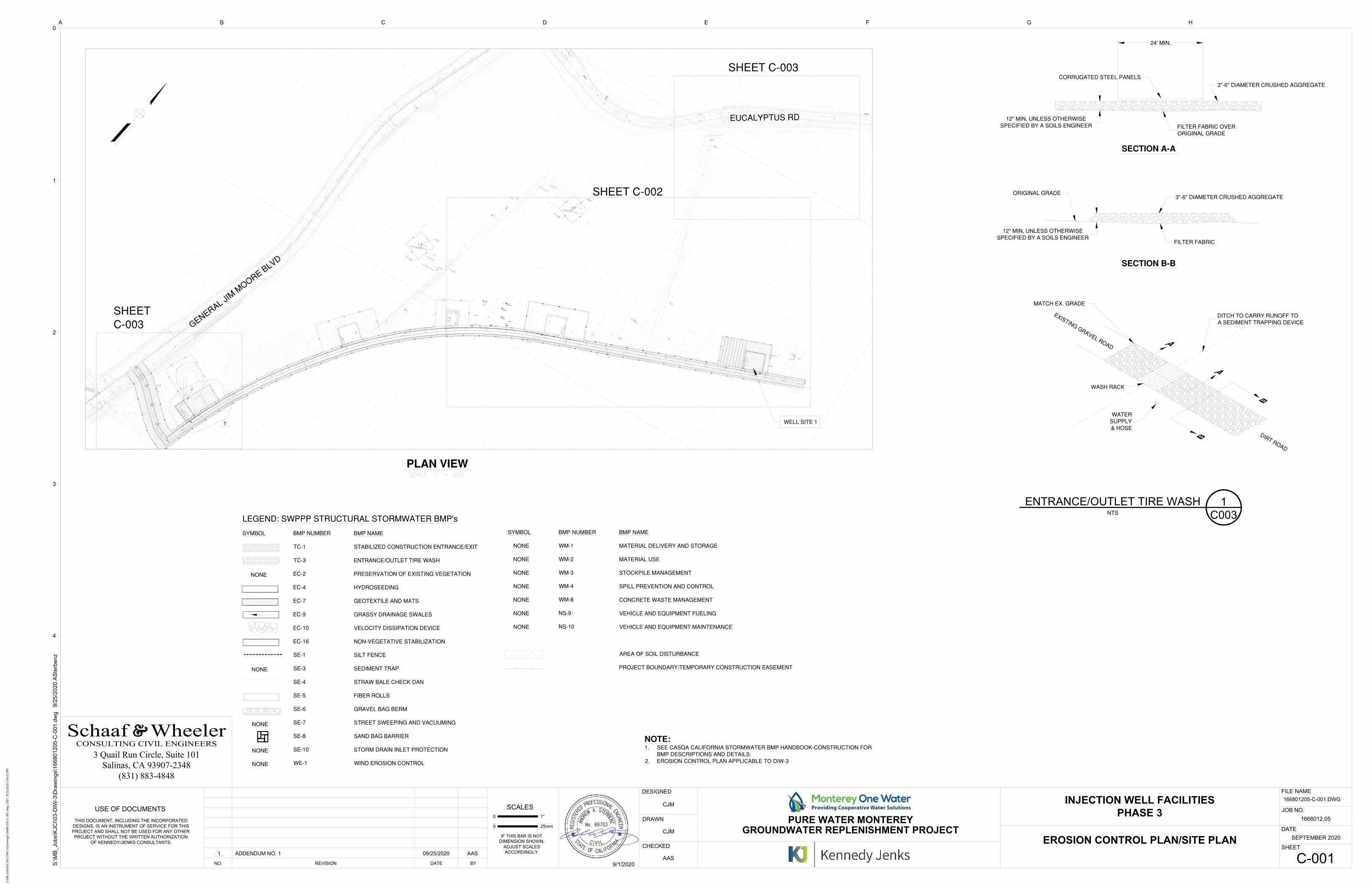
NTS
ENTRANCE/OUTLET TIRE WASH
C003
1
NONE
NONE
NONE
NONE
NONE
4
3
2
1
0
0
USE OF DOCUMENTS
25mm
SCALES
1"
CHECKED
DESIGNED
DRAWN
0
Kennedy/Jenks Consultants
DATE
SHEET
FILE NAME
JOB NO.
D E F G HA B C
IF THIS BAR IS NOT
DIMENSION SHOWN,
ADJUST SCALES
ACCORDINGLY.
THIS DOCUMENT, INCLUDING THE INCORPORATED
DESIGNS, IS AN INSTRUMENT OF SERVICE FOR THIS
PROJECT AND SHALL NOT BE USED FOR ANY OTHER
PROJECT WITHOUT THE WRITTEN AUTHORIZATION
OF KENNEDY/JENKS CONSULTANTS.
NO. REVISION DATE BY
1668012.05
PURE WATER MONTEREY
GROUNDWATER REPLENISHMENT PROJECT
INJECTION WELL FACILITIES
PHASE 3
SEPTEMBER 2020
S:\M
B_
Jo
bs\K
JC
I\0
3-D
IW
-3
\D
ra
win
gs\1
66
80
12
05
-C
-0
01
.d
wg 9
/2
5/2
02
0 A
Ste
rb
en
z
(831) 883-4848Salinas, CA 93907-2348
3 Quail Run Circle, Suite 101
9/1/2020
CJM
CJM
AAS
1 ADDENDUM NO. 1 09/25/2020 AAS
EROSION CONTROL PLAN/SITE PLAN
C-001
166801205-C-001.DWG
S:\M
B_Jo
bs\K
JC
I\03-D
IW
-3\D
raw
in
gs\166801205-C
-001.d
wg
, C
001, 9/25/2020 3:54:22 P
M
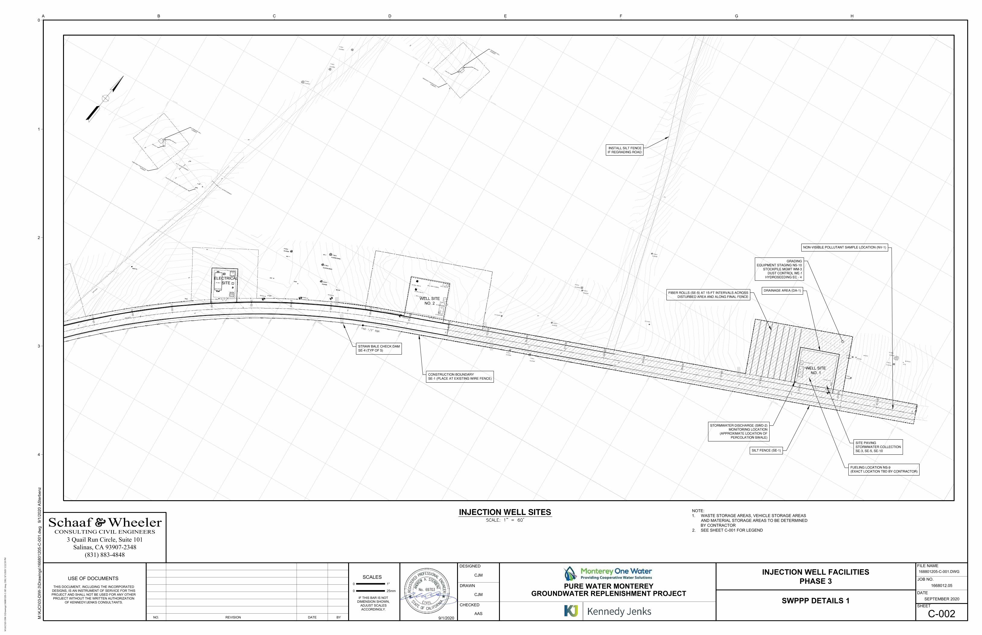
NOTE:
1. WASTE STORAGE AREAS, VEHICLE STORAGE AREAS
AND MATERIAL STORAGE AREAS TO BE DETERMINED
BY CONTRACTOR
2. SEE SHEET C-001 FOR LEGEND
4
3
2
1
0
0
USE OF DOCUMENTS
25mm
SCALES
1"
CHECKED
DESIGNED
DRAWN
0
Kennedy/Jenks Consultants
DATE
SHEET
FILE NAME
JOB NO.
D E F G HA B C
IF THIS BAR IS NOT
DIMENSION SHOWN,
ADJUST SCALES
ACCORDINGLY.
THIS DOCUMENT, INCLUDING THE INCORPORATED
DESIGNS, IS AN INSTRUMENT OF SERVICE FOR THIS
PROJECT AND SHALL NOT BE USED FOR ANY OTHER
PROJECT WITHOUT THE WRITTEN AUTHORIZATION
OF KENNEDY/JENKS CONSULTANTS.
NO. REVISION DATE BY
1668012.05
PURE WATER MONTEREY
GROUNDWATER REPLENISHMENT PROJECT
INJECTION WELL FACILITIES
PHASE 3
SEPTEMBER 2020
M:\K
JC
I\0
3-D
IW
-3
\D
ra
win
gs\1
66
80
12
05
-C
-0
01
.d
wg
9
/1
/2
02
0 A
Ste
rb
en
z
(831) 883-4848Salinas, CA 93907-2348
3 Quail Run Circle, Suite 101
9/1/2020
CJM
CJM
AAS
SWPPP DETAILS 1
C-002
168801205-C-001.DWG
M:\K
JC
I\03-D
IW
-3\D
raw
in
gs\166801205-C
-001.d
wg
, C
002, 9/1/2020 12:22:59 P
M
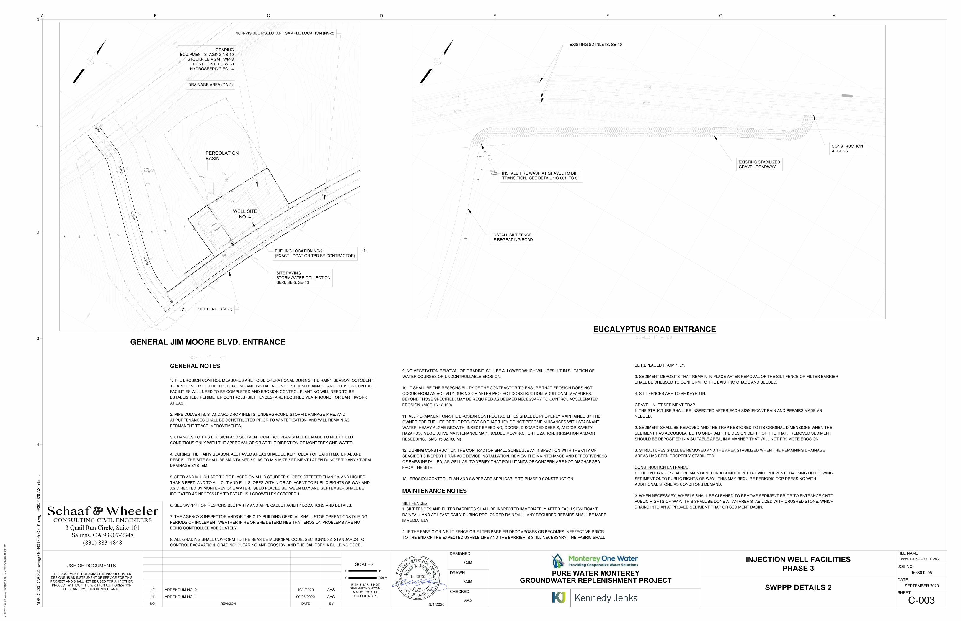
4
3
2
1
0
0
USE OF DOCUMENTS
25mm
SCALES
1"
CHECKED
DESIGNED
DRAWN
0
Kennedy/Jenks Consultants
DATE
SHEET
FILE NAME
JOB NO.
D E F G HA B C
IF THIS BAR IS NOT
DIMENSION SHOWN,
ADJUST SCALES
ACCORDINGLY.
THIS DOCUMENT, INCLUDING THE INCORPORATED
DESIGNS, IS AN INSTRUMENT OF SERVICE FOR THIS
PROJECT AND SHALL NOT BE USED FOR ANY OTHER
PROJECT WITHOUT THE WRITTEN AUTHORIZATION
OF KENNEDY/JENKS CONSULTANTS.
NO. REVISION DATE BY
1668012.05
PURE WATER MONTEREY
GROUNDWATER REPLENISHMENT PROJECT
INJECTION WELL FACILITIES
PHASE 3
SEPTEMBER 2020
M:\K
JC
I\0
3-D
IW
-3
\D
ra
win
gs\1
66
80
12
05
-C
-0
01
.d
wg
9
/3
0/2
02
0 A
Ste
rb
en
z
(831) 883-4848Salinas, CA 93907-2348
3 Quail Run Circle, Suite 101
9/1/2020
CJM
CJM
AAS
1 ADDENDUM NO. 1 09/25/2020 AAS
2 ADDENDUM NO. 2 10/1/2020 AAS
SWPPP DETAILS 2
C-003
166801205-C-001.DWG
M:\K
JC
I\03-D
IW
-3\D
raw
in
gs\166801205-C
-001.d
wg
, C
003, 9/30/2020 10:32:07 A
M
PWM Well Field Phase 3 127 August 2020
Appendix S: Contractor Activities Location Map
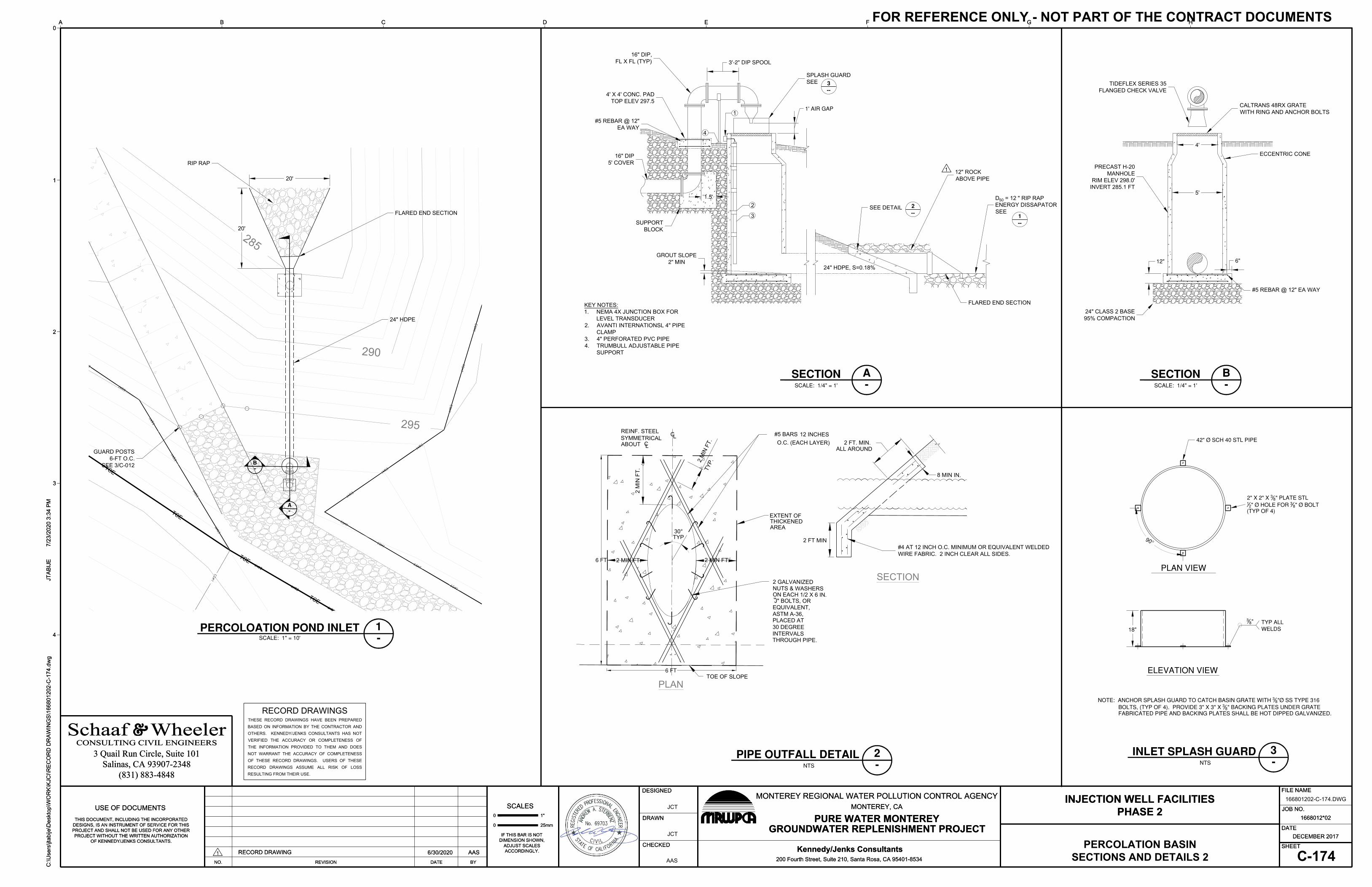
D50 = 12 " RIP RAPENERGY DISSAPATORSEE
--1
16" DIP,FL X FL (TYP)
1' AIR GAP
3'-2" DIP SPOOL
#5 REBAR @ 12" EA WAY
12"
CALTRANS 48RX GRATEWITH RING AND ANCHOR BOLTS
16" DIP5' COVER
TIDEFLEX SERIES 35FLANGED CHECK VALVE
6"
#5 REBAR @ 12"EA WAY
24" HDPE, S=0.18%
SEE DETAIL--2
1
PRECAST H-20MANHOLE
RIM ELEV 298.0'INVERT 285.1 FT
GROUT SLOPE2" MIN
3
2
24" CLASS 2 BASE95% COMPACTION
4' X 4' CONC. PADTOP ELEV 297.5
4'
5'
ECCENTRIC CONE
FLARED END SECTION
SPLASH GUARDSEE
--3
4
SUPPORTBLOCK
1.5'
12" ROCKABOVE PIPE
TCE
TCE
TCE
TCE
G E
N E
R A
L
J
I M
M
O O
R E
B
L V
D .
295
290
285
EQUIVALENT,
TYP
ASTM A-36,
30°
TOE OF SLOPEPLAN
O.C. (EACH LAYER)
J" BOLTS, OR
NUTS & WASHERS 2 GALVANIZED
REINF. STEELSYMMETRICAL
CL
SECTION
2 FT. MIN.ABOUT
2 FT MIN
ALL AROUND
THICKENEDEXTENT OF
PLACED AT
ON EACH 1/2 X 6 IN.
CL
12 INCHES #5 BARS
TYP.
2 M
IN F
T.
2 MIN FT.
2 M
IN F
T.
2 MIN FT.
8 MIN IN.
30 DEGREEINTERVALS THROUGH PIPE.
AREA
6 FT
6 FT
#4 AT 12 INCH O.C. MINIMUM OR EQUIVALENT WELDEDWIRE FABRIC. 2 INCH CLEAR ALL SIDES.
42" Ø SCH 40 STL PIPE
2" X 2" X 3 8" PLATE STL12" Ø HOLE FOR 3 8" Ø BOLT
(TYP OF 4)
90°
PLAN VIEW
ELEVATION VIEW
TYP ALLWELDS
38"
18"
NOTE: ANCHOR SPLASH GUARD TO CATCH BASIN GRATE WITH 3 8"Ø SS TYPE 316 BOLTS, (TYP OF 4). PROVIDE 3" X 3" X 3 8" BACKING PLATES UNDER GRATE
FABRICATED PIPE AND BACKING PLATES SHALL BE HOT DIPPED GALVANIZED.
4
3
2
1
0
0USE OF DOCUMENTS
25mm
SCALES1"
CHECKED
DESIGNED
DRAWN
0
Kennedy/Jenks Consultants
DATE
SHEET
FILE NAME
JOB NO.
D E F G HA B C
IF THIS BAR IS NOTDIMENSION SHOWN,
ADJUST SCALESACCORDINGLY.
THIS DOCUMENT, INCLUDING THE INCORPORATEDDESIGNS, IS AN INSTRUMENT OF SERVICE FOR THISPROJECT AND SHALL NOT BE USED FOR ANY OTHERPROJECT WITHOUT THE WRITTEN AUTHORIZATION
OF KENNEDY/JENKS CONSULTANTS.
NO. REVISION DATE BYC:\U
sers
\jtab
ije\D
eskt
op\W
OR
K\K
JCI\R
EC
OR
D D
RA
WIN
GS
\166
8012
02-C
-174
.dw
gJT
AB
IJE
7/2
3/20
20 3
:34
PM
INJECTION WELL FACILITIESPHASE 2
1668012*02
DECEMBER 2017
MONTEREY REGIONAL WATER POLLUTION CONTROL AGENCYMONTEREY, CA
PURE WATER MONTEREYGROUNDWATER REPLENISHMENT PROJECT
200 Fourth Street, Suite 210, Santa Rosa, CA 95401-8534
(831) 883-4848Salinas, CA 93907-2348
3 Quail Run Circle, Suite 101CONSULTING CIVIL ENGINEERS
Schaaf Wheeler
RECORD DRAWING 6/30/2020 AASPERCOLATION BASIN
SECTIONS AND DETAILS 2 C-174AAS
JCT
JCT
4
3
2
1
0
0USE OF DOCUMENTS
25mm
SCALES1"
CHECKED
DESIGNED
DRAWN
0
Kennedy/Jenks Consultants
DATE
SHEET
FILE NAME
JOB NO.
D E F G HA B C
IF THIS BAR IS NOTDIMENSION SHOWN,
ADJUST SCALESACCORDINGLY.
THIS DOCUMENT, INCLUDING THE INCORPORATEDDESIGNS, IS AN INSTRUMENT OF SERVICE FOR THISPROJECT AND SHALL NOT BE USED FOR ANY OTHERPROJECT WITHOUT THE WRITTEN AUTHORIZATION
OF KENNEDY/JENKS CONSULTANTS.
NO. REVISION DATE BYC:\U
sers
\jtab
ije\D
eskt
op\W
OR
K\K
JCI\R
EC
OR
D D
RA
WIN
GS
\166
8012
02-C
-174
.dw
gJT
AB
IJE
7/2
3/20
20 3
:34
PM
INJECTION WELL FACILITIESPHASE 2
1668012*02
DECEMBER 2017
MONTEREY REGIONAL WATER POLLUTION CONTROL AGENCYMONTEREY, CA
PURE WATER MONTEREYGROUNDWATER REPLENISHMENT PROJECT
200 Fourth Street, Suite 210, Santa Rosa, CA 95401-8534
(831) 883-4848Salinas, CA 93907-2348
3 Quail Run Circle, Suite 101CONSULTING CIVIL ENGINEERS
Schaaf Wheeler
RECORD DRAWING 6/30/2020 AAS
-B
-A
SCALE: 1/4" = 1'
SECTION-A
SCALE: 1/4" = 1'
SECTION-B
SCALE: 1" = 10'
PERCOLOATION POND INLET
166801202-C-174.DWG
-1
NTS
PIPE OUTFALL DETAIL-2
20'
20'
RIP RAP
GUARD POSTS6-FT O.C.
SEE 3/C-012
KEY NOTES:1. NEMA 4X JUNCTION BOX FOR
LEVEL TRANSDUCER2. AVANTI INTERNATIONSL 4" PIPE
CLAMP3. 4" PERFORATED PVC PIPE4. TRUMBULL ADJUSTABLE PIPE
SUPPORT
FLARED END SECTION
24" HDPE
NTS
INLET SPLASH GUARD-3
1
1
RECORD DRAWINGSTHESE RECORD DRAWINGS HAVE BEEN PREPAREDBASED ON INFORMATION BY THE CONTRACTOR ANDOTHERS. KENNEDY/JENKS CONSULTANTS HAS NOTVERIFIED THE ACCURACY OR COMPLETENESS OFTHE INFORMATION PROVIDED TO THEM AND DOESNOT WARRANT THE ACCURACY OF COMPLETENESSOF THESE RECORD DRAWINGS. USERS OF THESERECORD DRAWINGS ASSUME ALL RISK OF LOSSRESULTING FROM THEIR USE.
FOR REFERENCE ONLY - NOT PART OF THE CONTRACT DOCUMENTS
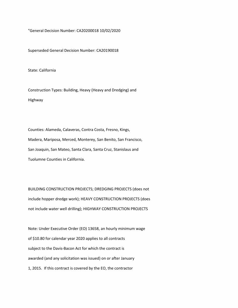
"General Decision Number: CA20200018 10/02/2020
Superseded General Decision Number: CA20190018
State: California
Construction Types: Building, Heavy (Heavy and Dredging) and
Highway
Counties: Alameda, Calaveras, Contra Costa, Fresno, Kings,
Madera, Mariposa, Merced, Monterey, San Benito, San Francisco,
San Joaquin, San Mateo, Santa Clara, Santa Cruz, Stanislaus and
Tuolumne Counties in California.
BUILDING CONSTRUCTION PROJECTS; DREDGING PROJECTS (does not
include hopper dredge work); HEAVY CONSTRUCTION PROJECTS (does
not include water well drilling); HIGHWAY CONSTRUCTION PROJECTS
Note: Under Executive Order (EO) 13658, an hourly minimum wage
of $10.80 for calendar year 2020 applies to all contracts
subject to the Davis-Bacon Act for which the contract is
awarded (and any solicitation was issued) on or after January
1, 2015. If this contract is covered by the EO, the contractor

must pay all workers in any classification listed on this wage
determination at least $10.80 per hour (or the applicable wage
rate listed on this wage determination, if it is higher) for
all hours spent performing on the contract in calendar year
2020. If this contract is covered by the EO and a
classification considered necessary for performance of work on
the contract does not appear on this wage determination, the
contractor must pay workers in that classification at least the
wage rate determined through the conformance process set forth
in 29 CFR 5.5(a)(1)(ii) (or the EO minimum wage rate,if it is
higher than the conformed wage rate). The EO minimum wage rate
will be adjusted annually. Please note that this EO applies to
the above-mentioned types of contracts entered into by the
federal government that are subject to the Davis-Bacon Act
itself, but it does not apply to contracts subject only to the
Davis-Bacon Related Acts, including those set forth at 29 CFR
5.1(a)(2)-(60). Additional information on contractor
requirements and worker protections under the EO is available
at www.dol.gov/whd/govcontracts.
Modification Number Publication Date
0 01/03/2020
1 01/10/2020
2 01/24/2020
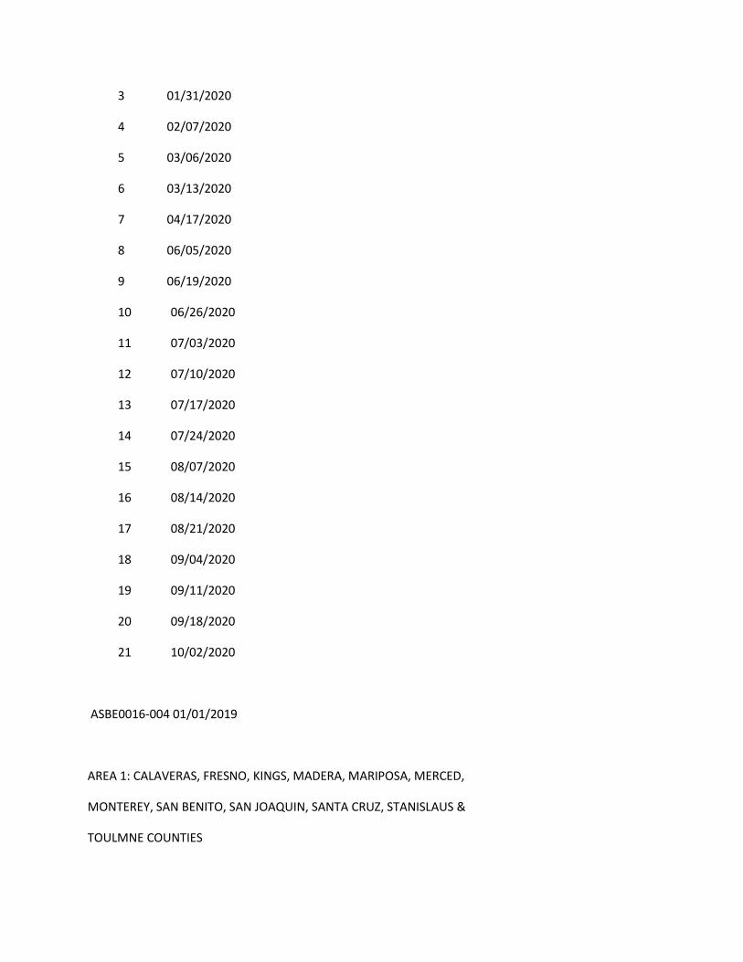
3 01/31/2020
4 02/07/2020
5 03/06/2020
6 03/13/2020
7 04/17/2020
8 06/05/2020
9 06/19/2020
10 06/26/2020
11 07/03/2020
12 07/10/2020
13 07/17/2020
14 07/24/2020
15 08/07/2020
16 08/14/2020
17 08/21/2020
18 09/04/2020
19 09/11/2020
20 09/18/2020
21 10/02/2020
ASBE0016-004 01/01/2019
AREA 1: CALAVERAS, FRESNO, KINGS, MADERA, MARIPOSA, MERCED,
MONTEREY, SAN BENITO, SAN JOAQUIN, SANTA CRUZ, STANISLAUS &
TOULMNE COUNTIES

AREA 2: ALAMEDA, CONTRA COSTA, SAN FRANSICO, SAN MATEO & SANTA
CLARA COUNTIES
Rates Fringes
Asbestos Removal
worker/hazardous material
handler (Includes
preparation, wetting,
stripping, removal,
scrapping, vacuuming, bagging
and disposing of all
insulation materials from
mechanical systems, whether
they contain asbestos or not)
Area 1......................$ 28.20 9.27
Area 2......................$ 36.53 9.27
----------------------------------------------------------------
ASBE0016-008 01/01/2020
AREA 1: ALAMEDA, CONTRA COSTA, MONTEREY, SAN BENITO, SAN
FRANSICO, SAN MATEO, SANTA CLARA, & SANTA CRUZ
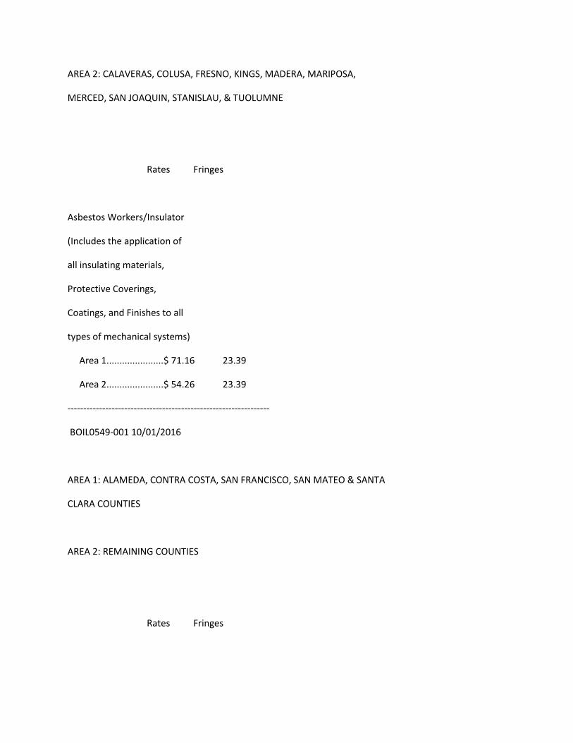
AREA 2: CALAVERAS, COLUSA, FRESNO, KINGS, MADERA, MARIPOSA,
MERCED, SAN JOAQUIN, STANISLAU, & TUOLUMNE
Rates Fringes
Asbestos Workers/Insulator
(Includes the application of
all insulating materials,
Protective Coverings,
Coatings, and Finishes to all
types of mechanical systems)
Area 1......................$ 71.16 23.39
Area 2......................$ 54.26 23.39
----------------------------------------------------------------
BOIL0549-001 10/01/2016
AREA 1: ALAMEDA, CONTRA COSTA, SAN FRANCISCO, SAN MATEO & SANTA
CLARA COUNTIES
AREA 2: REMAINING COUNTIES
Rates Fringes
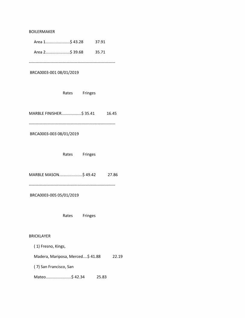
BOILERMAKER
Area 1......................$ 43.28 37.91
Area 2......................$ 39.68 35.71
----------------------------------------------------------------
BRCA0003-001 08/01/2019
Rates Fringes
MARBLE FINISHER..................$ 35.41 16.45
----------------------------------------------------------------
BRCA0003-003 08/01/2019
Rates Fringes
MARBLE MASON.....................$ 49.42 27.86
----------------------------------------------------------------
BRCA0003-005 05/01/2019
Rates Fringes
BRICKLAYER
( 1) Fresno, Kings,
Madera, Mariposa, Merced....$ 41.88 22.19
( 7) San Francisco, San
Mateo.......................$ 42.34 25.83
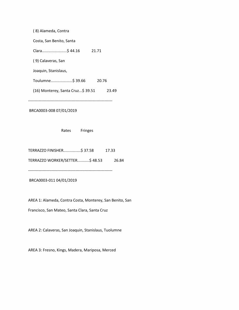
( 8) Alameda, Contra
Costa, San Benito, Santa
Clara.......................$ 44.16 21.71
( 9) Calaveras, San
Joaquin, Stanislaus,
Toulumne....................$ 39.66 20.76
(16) Monterey, Santa Cruz...$ 39.51 23.49
----------------------------------------------------------------
BRCA0003-008 07/01/2019
Rates Fringes
TERRAZZO FINISHER................$ 37.58 17.33
TERRAZZO WORKER/SETTER...........$ 48.53 26.84
----------------------------------------------------------------
BRCA0003-011 04/01/2019
AREA 1: Alameda, Contra Costa, Monterey, San Benito, San
Francisco, San Mateo, Santa Clara, Santa Cruz
AREA 2: Calaveras, San Joaquin, Stanislaus, Tuolumne
AREA 3: Fresno, Kings, Madera, Mariposa, Merced
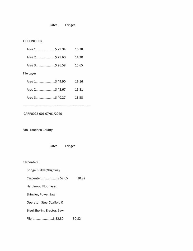
Rates Fringes
TILE FINISHER
Area 1......................$ 29.94 16.38
Area 2......................$ 25.60 14.30
Area 3......................$ 26.58 15.65
Tile Layer
Area 1......................$ 49.90 19.16
Area 2......................$ 42.67 16.81
Area 3......................$ 40.27 18.58
----------------------------------------------------------------
CARP0022-001 07/01/2020
San Francisco County
Rates Fringes
Carpenters
Bridge Builder/Highway
Carpenter...................$ 52.65 30.82
Hardwood Floorlayer,
Shingler, Power Saw
Operator, Steel Scaffold &
Steel Shoring Erector, Saw
Filer.......................$ 52.80 30.82
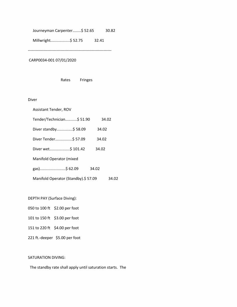
Journeyman Carpenter........$ 52.65 30.82
Millwright..................$ 52.75 32.41
----------------------------------------------------------------
CARP0034-001 07/01/2020
Rates Fringes
Diver
Assistant Tender, ROV
Tender/Technician...........$ 51.90 34.02
Diver standby...............$ 58.09 34.02
Diver Tender................$ 57.09 34.02
Diver wet...................$ 101.42 34.02
Manifold Operator (mixed
gas)........................$ 62.09 34.02
Manifold Operator (Standby).$ 57.09 34.02
DEPTH PAY (Surface Diving):
050 to 100 ft $2.00 per foot
101 to 150 ft $3.00 per foot
151 to 220 ft $4.00 per foot
221 ft.-deeper $5.00 per foot
SATURATION DIVING:
The standby rate shall apply until saturation starts. The
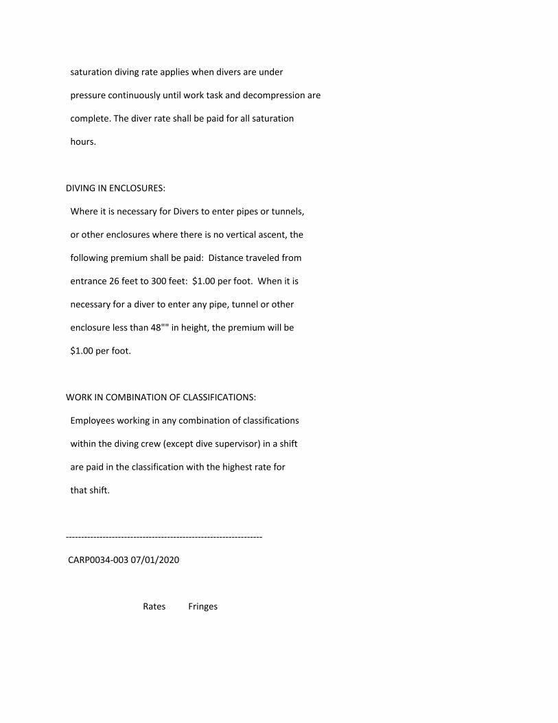
saturation diving rate applies when divers are under
pressure continuously until work task and decompression are
complete. The diver rate shall be paid for all saturation
hours.
DIVING IN ENCLOSURES:
Where it is necessary for Divers to enter pipes or tunnels,
or other enclosures where there is no vertical ascent, the
following premium shall be paid: Distance traveled from
entrance 26 feet to 300 feet: $1.00 per foot. When it is
necessary for a diver to enter any pipe, tunnel or other
enclosure less than 48"" in height, the premium will be
$1.00 per foot.
WORK IN COMBINATION OF CLASSIFICATIONS:
Employees working in any combination of classifications
within the diving crew (except dive supervisor) in a shift
are paid in the classification with the highest rate for
that shift.
----------------------------------------------------------------
CARP0034-003 07/01/2020
Rates Fringes
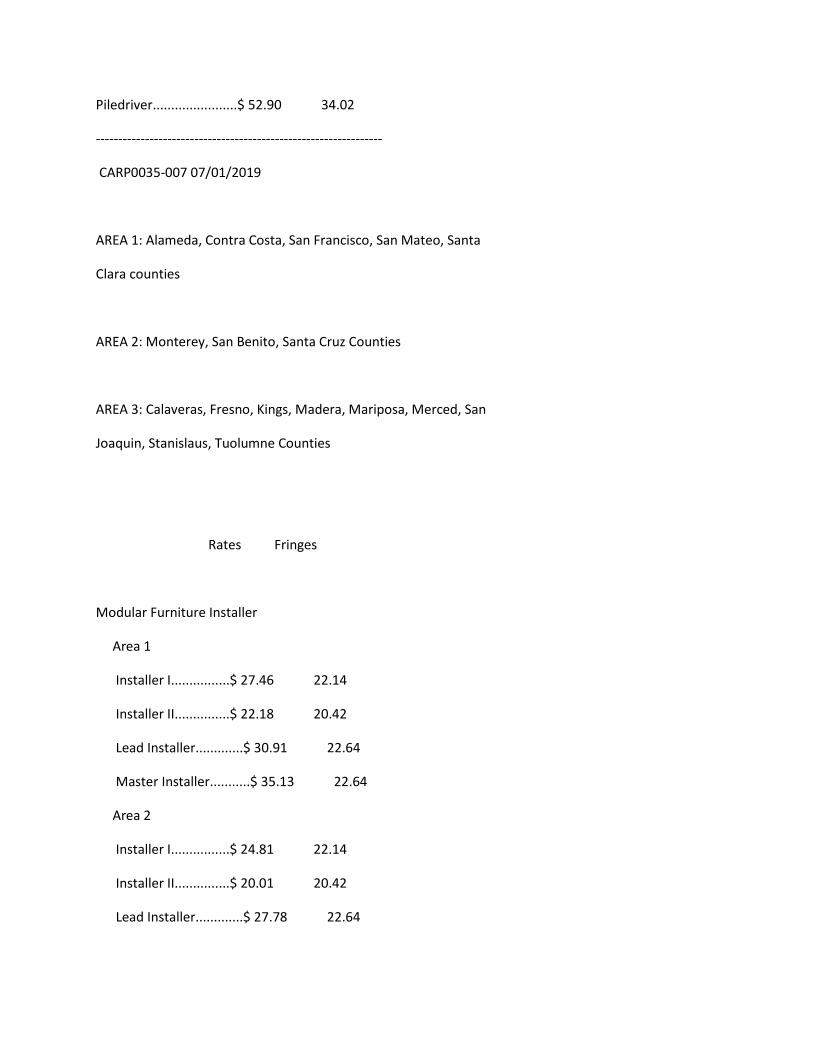
Piledriver.......................$ 52.90 34.02
----------------------------------------------------------------
CARP0035-007 07/01/2019
AREA 1: Alameda, Contra Costa, San Francisco, San Mateo, Santa
Clara counties
AREA 2: Monterey, San Benito, Santa Cruz Counties
AREA 3: Calaveras, Fresno, Kings, Madera, Mariposa, Merced, San
Joaquin, Stanislaus, Tuolumne Counties
Rates Fringes
Modular Furniture Installer
Area 1
Installer I................$ 27.46 22.14
Installer II...............$ 22.18 20.42
Lead Installer.............$ 30.91 22.64
Master Installer...........$ 35.13 22.64
Area 2
Installer I................$ 24.81 22.14
Installer II...............$ 20.01 20.42
Lead Installer.............$ 27.78 22.64
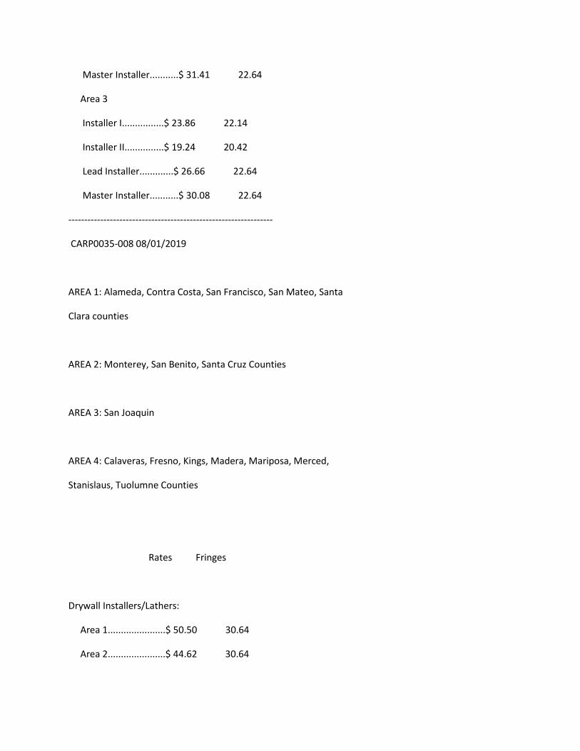
Master Installer...........$ 31.41 22.64
Area 3
Installer I................$ 23.86 22.14
Installer II...............$ 19.24 20.42
Lead Installer.............$ 26.66 22.64
Master Installer...........$ 30.08 22.64
----------------------------------------------------------------
CARP0035-008 08/01/2019
AREA 1: Alameda, Contra Costa, San Francisco, San Mateo, Santa
Clara counties
AREA 2: Monterey, San Benito, Santa Cruz Counties
AREA 3: San Joaquin
AREA 4: Calaveras, Fresno, Kings, Madera, Mariposa, Merced,
Stanislaus, Tuolumne Counties
Rates Fringes
Drywall Installers/Lathers:
Area 1......................$ 50.50 30.64
Area 2......................$ 44.62 30.64
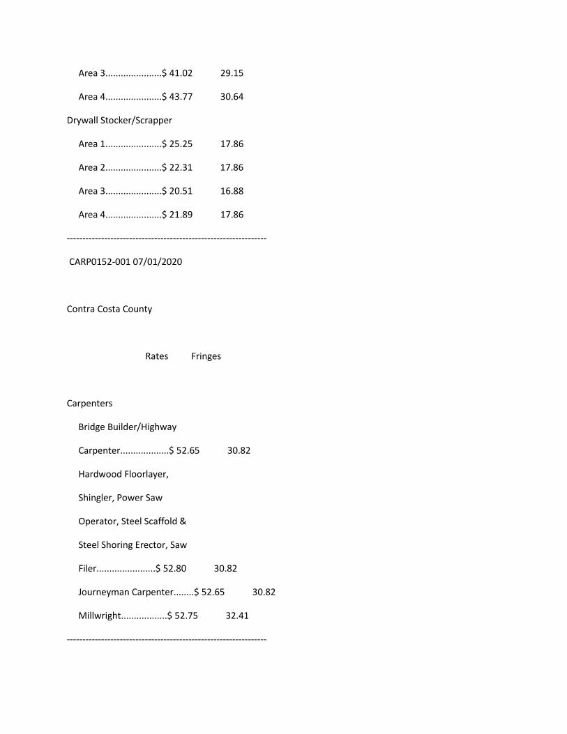
Area 3......................$ 41.02 29.15
Area 4......................$ 43.77 30.64
Drywall Stocker/Scrapper
Area 1......................$ 25.25 17.86
Area 2......................$ 22.31 17.86
Area 3......................$ 20.51 16.88
Area 4......................$ 21.89 17.86
----------------------------------------------------------------
CARP0152-001 07/01/2020
Contra Costa County
Rates Fringes
Carpenters
Bridge Builder/Highway
Carpenter...................$ 52.65 30.82
Hardwood Floorlayer,
Shingler, Power Saw
Operator, Steel Scaffold &
Steel Shoring Erector, Saw
Filer.......................$ 52.80 30.82
Journeyman Carpenter........$ 52.65 30.82
Millwright..................$ 52.75 32.41
----------------------------------------------------------------
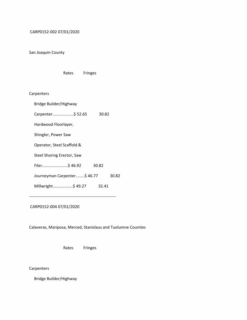
CARP0152-002 07/01/2020
San Joaquin County
Rates Fringes
Carpenters
Bridge Builder/Highway
Carpenter...................$ 52.65 30.82
Hardwood Floorlayer,
Shingler, Power Saw
Operator, Steel Scaffold &
Steel Shoring Erector, Saw
Filer.......................$ 46.92 30.82
Journeyman Carpenter........$ 46.77 30.82
Millwright..................$ 49.27 32.41
----------------------------------------------------------------
CARP0152-004 07/01/2020
Calaveras, Mariposa, Merced, Stanislaus and Tuolumne Counties
Rates Fringes
Carpenters
Bridge Builder/Highway
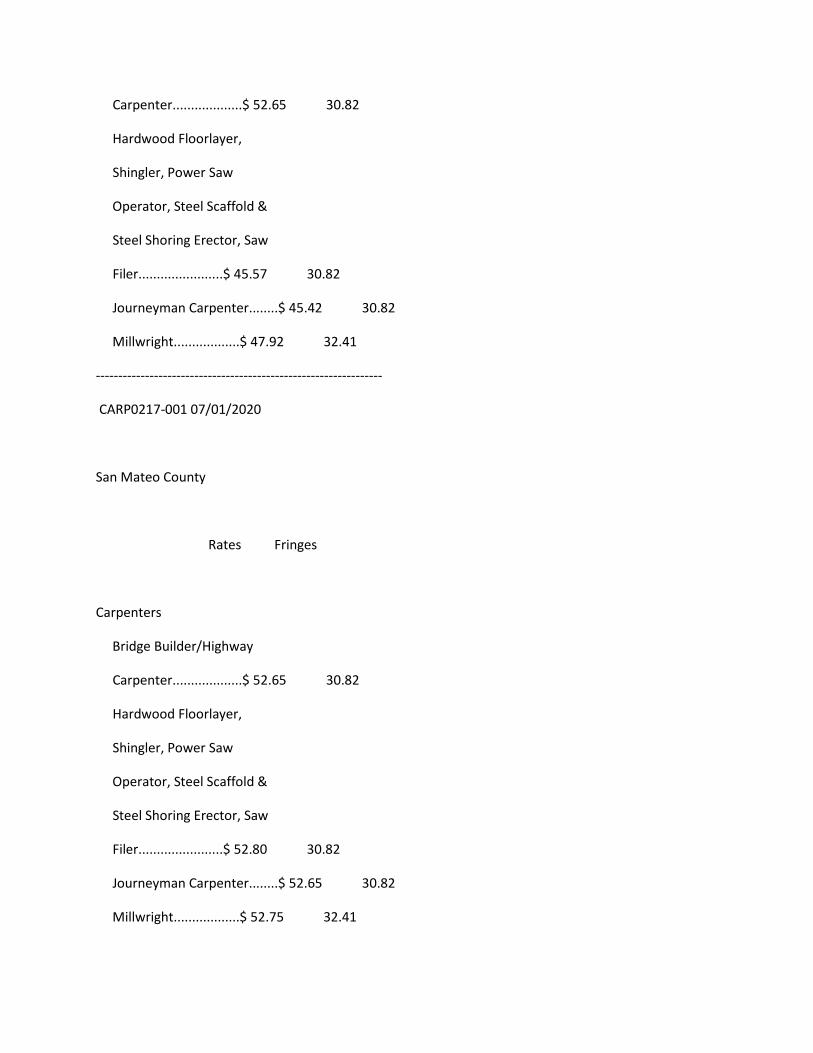
Carpenter...................$ 52.65 30.82
Hardwood Floorlayer,
Shingler, Power Saw
Operator, Steel Scaffold &
Steel Shoring Erector, Saw
Filer.......................$ 45.57 30.82
Journeyman Carpenter........$ 45.42 30.82
Millwright..................$ 47.92 32.41
----------------------------------------------------------------
CARP0217-001 07/01/2020
San Mateo County
Rates Fringes
Carpenters
Bridge Builder/Highway
Carpenter...................$ 52.65 30.82
Hardwood Floorlayer,
Shingler, Power Saw
Operator, Steel Scaffold &
Steel Shoring Erector, Saw
Filer.......................$ 52.80 30.82
Journeyman Carpenter........$ 52.65 30.82
Millwright..................$ 52.75 32.41
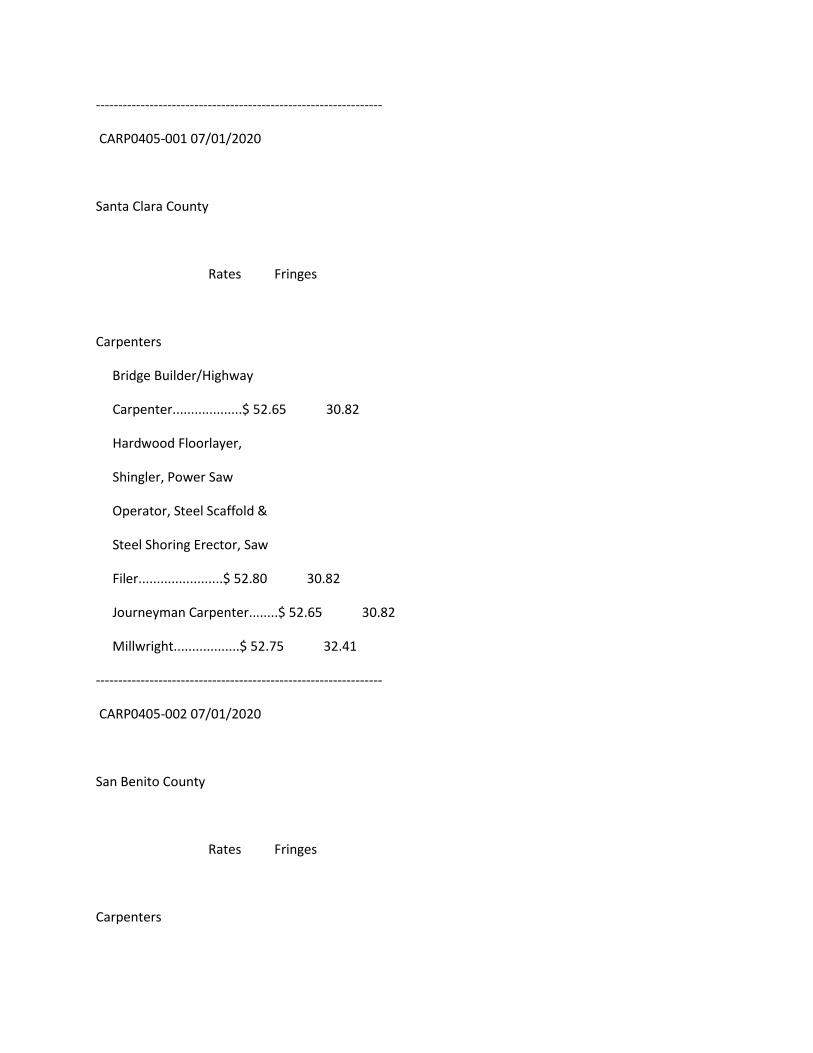
----------------------------------------------------------------
CARP0405-001 07/01/2020
Santa Clara County
Rates Fringes
Carpenters
Bridge Builder/Highway
Carpenter...................$ 52.65 30.82
Hardwood Floorlayer,
Shingler, Power Saw
Operator, Steel Scaffold &
Steel Shoring Erector, Saw
Filer.......................$ 52.80 30.82
Journeyman Carpenter........$ 52.65 30.82
Millwright..................$ 52.75 32.41
----------------------------------------------------------------
CARP0405-002 07/01/2020
San Benito County
Rates Fringes
Carpenters
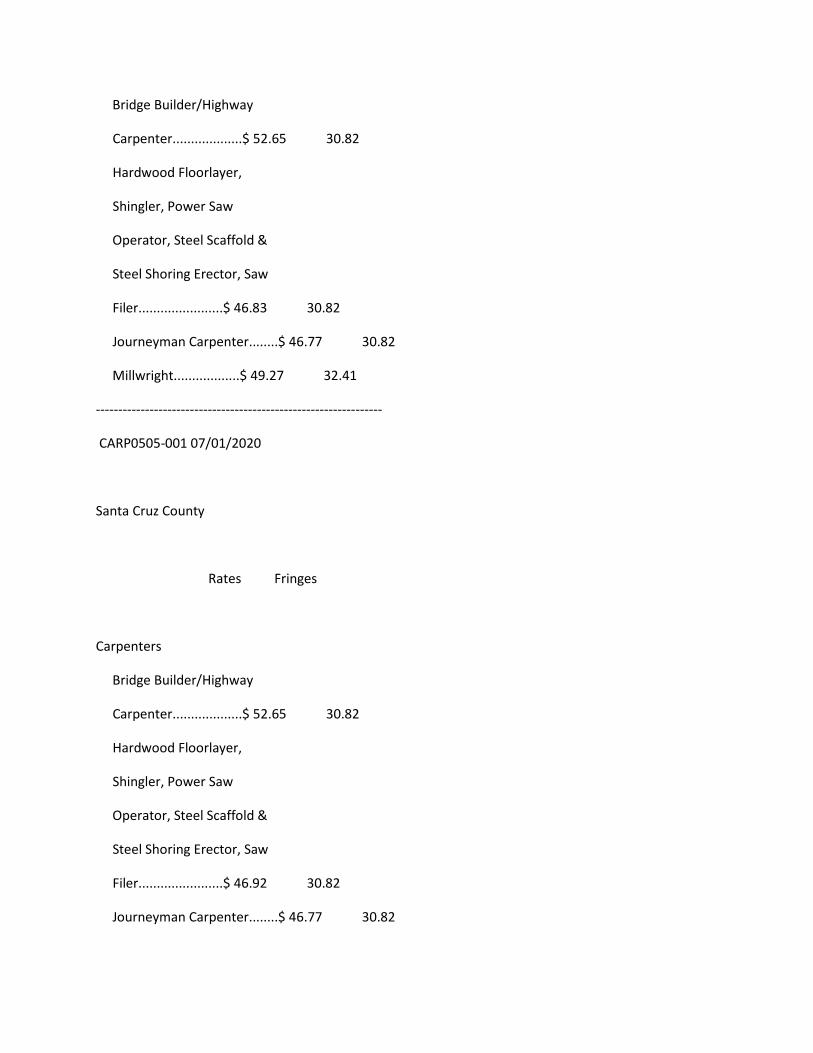
Bridge Builder/Highway
Carpenter...................$ 52.65 30.82
Hardwood Floorlayer,
Shingler, Power Saw
Operator, Steel Scaffold &
Steel Shoring Erector, Saw
Filer.......................$ 46.83 30.82
Journeyman Carpenter........$ 46.77 30.82
Millwright..................$ 49.27 32.41
----------------------------------------------------------------
CARP0505-001 07/01/2020
Santa Cruz County
Rates Fringes
Carpenters
Bridge Builder/Highway
Carpenter...................$ 52.65 30.82
Hardwood Floorlayer,
Shingler, Power Saw
Operator, Steel Scaffold &
Steel Shoring Erector, Saw
Filer.......................$ 46.92 30.82
Journeyman Carpenter........$ 46.77 30.82
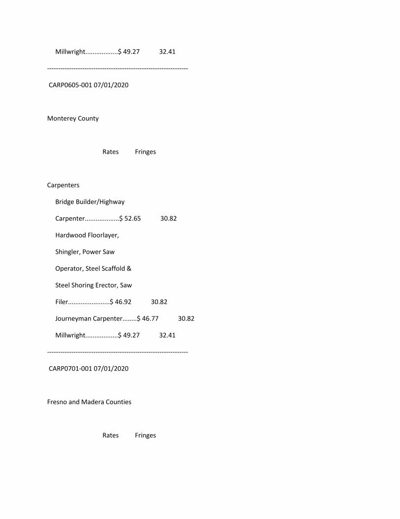
Millwright..................$ 49.27 32.41
----------------------------------------------------------------
CARP0605-001 07/01/2020
Monterey County
Rates Fringes
Carpenters
Bridge Builder/Highway
Carpenter...................$ 52.65 30.82
Hardwood Floorlayer,
Shingler, Power Saw
Operator, Steel Scaffold &
Steel Shoring Erector, Saw
Filer.......................$ 46.92 30.82
Journeyman Carpenter........$ 46.77 30.82
Millwright..................$ 49.27 32.41
----------------------------------------------------------------
CARP0701-001 07/01/2020
Fresno and Madera Counties
Rates Fringes
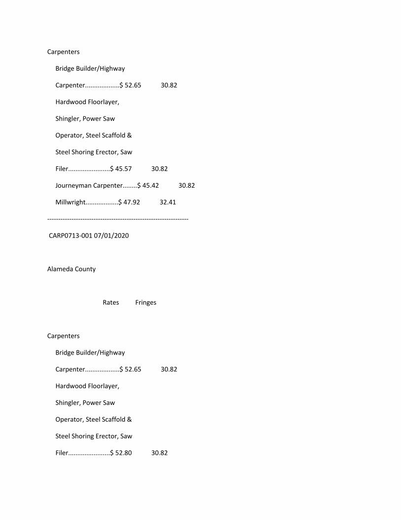
Carpenters
Bridge Builder/Highway
Carpenter...................$ 52.65 30.82
Hardwood Floorlayer,
Shingler, Power Saw
Operator, Steel Scaffold &
Steel Shoring Erector, Saw
Filer.......................$ 45.57 30.82
Journeyman Carpenter........$ 45.42 30.82
Millwright..................$ 47.92 32.41
----------------------------------------------------------------
CARP0713-001 07/01/2020
Alameda County
Rates Fringes
Carpenters
Bridge Builder/Highway
Carpenter...................$ 52.65 30.82
Hardwood Floorlayer,
Shingler, Power Saw
Operator, Steel Scaffold &
Steel Shoring Erector, Saw
Filer.......................$ 52.80 30.82
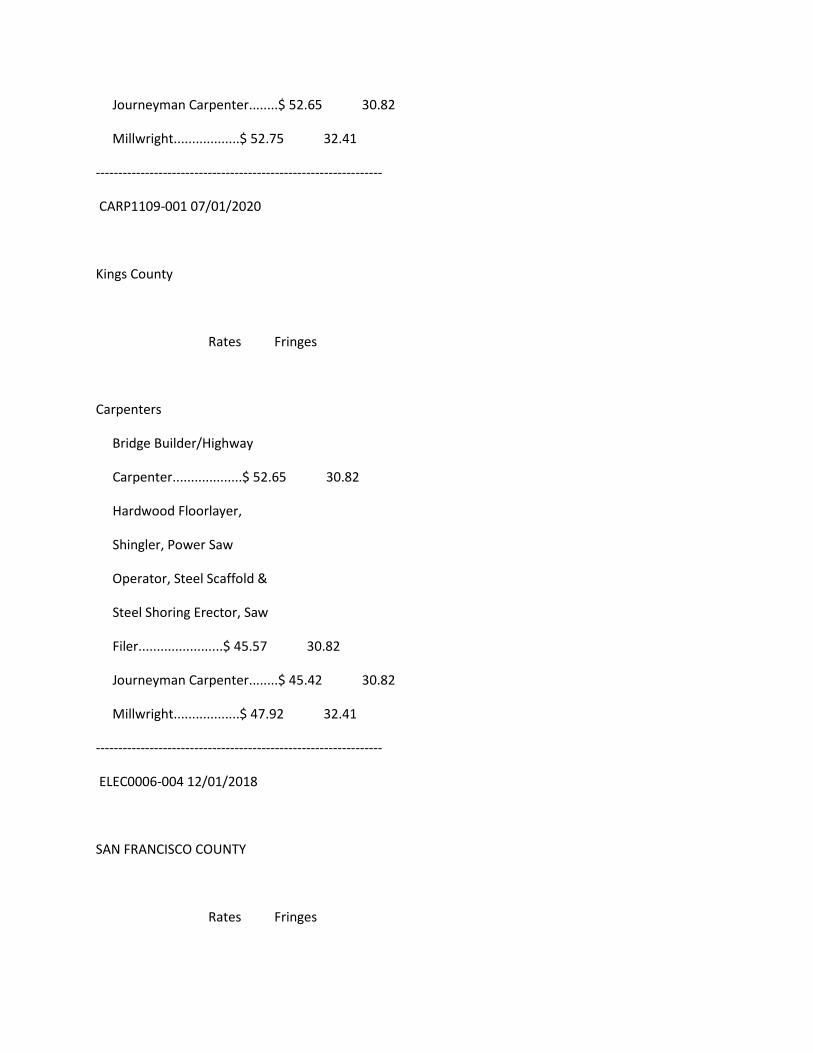
Journeyman Carpenter........$ 52.65 30.82
Millwright..................$ 52.75 32.41
----------------------------------------------------------------
CARP1109-001 07/01/2020
Kings County
Rates Fringes
Carpenters
Bridge Builder/Highway
Carpenter...................$ 52.65 30.82
Hardwood Floorlayer,
Shingler, Power Saw
Operator, Steel Scaffold &
Steel Shoring Erector, Saw
Filer.......................$ 45.57 30.82
Journeyman Carpenter........$ 45.42 30.82
Millwright..................$ 47.92 32.41
----------------------------------------------------------------
ELEC0006-004 12/01/2018
SAN FRANCISCO COUNTY
Rates Fringes
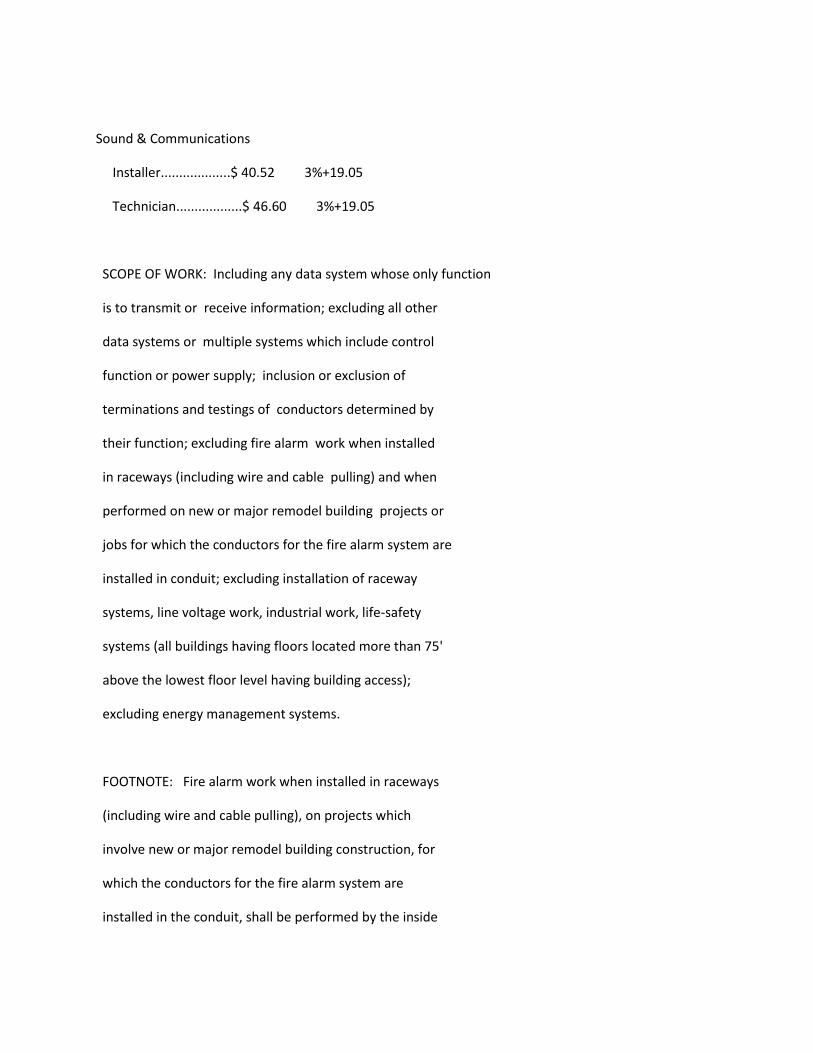
Sound & Communications
Installer...................$ 40.52 3%+19.05
Technician..................$ 46.60 3%+19.05
SCOPE OF WORK: Including any data system whose only function
is to transmit or receive information; excluding all other
data systems or multiple systems which include control
function or power supply; inclusion or exclusion of
terminations and testings of conductors determined by
their function; excluding fire alarm work when installed
in raceways (including wire and cable pulling) and when
performed on new or major remodel building projects or
jobs for which the conductors for the fire alarm system are
installed in conduit; excluding installation of raceway
systems, line voltage work, industrial work, life-safety
systems (all buildings having floors located more than 75'
above the lowest floor level having building access);
excluding energy management systems.
FOOTNOTE: Fire alarm work when installed in raceways
(including wire and cable pulling), on projects which
involve new or major remodel building construction, for
which the conductors for the fire alarm system are
installed in the conduit, shall be performed by the inside
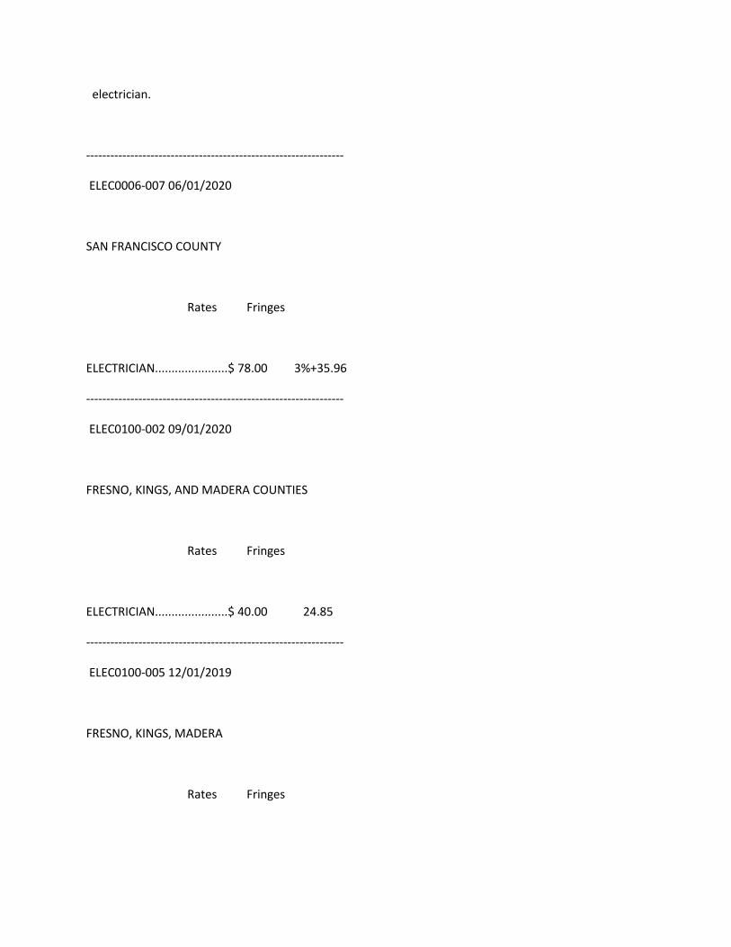
electrician.
----------------------------------------------------------------
ELEC0006-007 06/01/2020
SAN FRANCISCO COUNTY
Rates Fringes
ELECTRICIAN......................$ 78.00 3%+35.96
----------------------------------------------------------------
ELEC0100-002 09/01/2020
FRESNO, KINGS, AND MADERA COUNTIES
Rates Fringes
ELECTRICIAN......................$ 40.00 24.85
----------------------------------------------------------------
ELEC0100-005 12/01/2019
FRESNO, KINGS, MADERA
Rates Fringes

Communications System
Installer...................$ 35.25 20.86
Technician..................$ 40.54 21.02
SCOPE OF WORK
Includes the installation testing, service and maintenance,
of the following systems which utilize the transmission
and/or transference of voice, sound, vision and digital for
commercial, education, security and entertainment purposes
for the following: TV monitoring and surveillance,
background-foreground music, intercom and telephone
interconnect, inventory control systems, microwave
transmission, multi-media, multiplex, nurse call system,
radio page, school intercom and sound, burglar alarms, and
low voltage master clock systems.
A. SOUND AND VOICE TRANSMISSION/TRANSFERENCE SYSTEMS
Background foreground music, Intercom and telephone
interconnect systems, Telephone systems Nurse call systems,
Radio page systems, School intercom and sound systems,
Burglar alarm systems, Low voltage, master clock systems,
Multi-media/multiplex systems, Sound and musical
entertainment systems, RF systems, Antennas and Wave Guide,
B. FIRE ALARM SYSTEMS Installation, wire pulling and testing
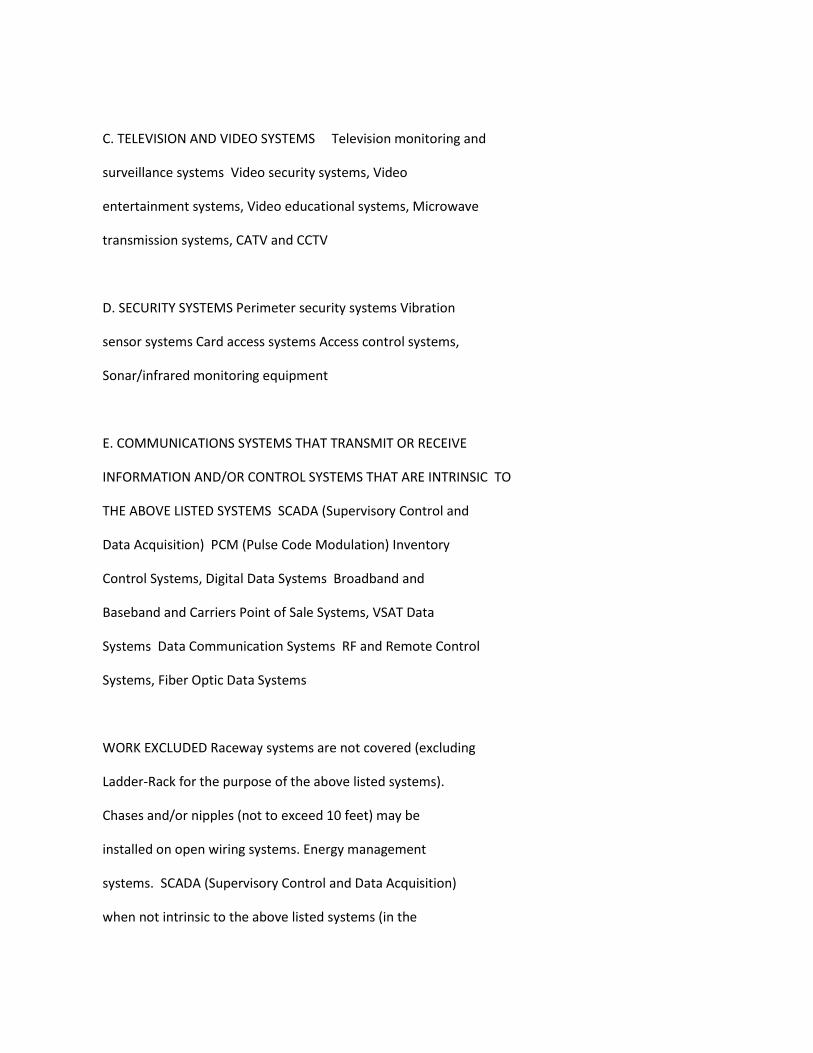
C. TELEVISION AND VIDEO SYSTEMS Television monitoring and
surveillance systems Video security systems, Video
entertainment systems, Video educational systems, Microwave
transmission systems, CATV and CCTV
D. SECURITY SYSTEMS Perimeter security systems Vibration
sensor systems Card access systems Access control systems,
Sonar/infrared monitoring equipment
E. COMMUNICATIONS SYSTEMS THAT TRANSMIT OR RECEIVE
INFORMATION AND/OR CONTROL SYSTEMS THAT ARE INTRINSIC TO
THE ABOVE LISTED SYSTEMS SCADA (Supervisory Control and
Data Acquisition) PCM (Pulse Code Modulation) Inventory
Control Systems, Digital Data Systems Broadband and
Baseband and Carriers Point of Sale Systems, VSAT Data
Systems Data Communication Systems RF and Remote Control
Systems, Fiber Optic Data Systems
WORK EXCLUDED Raceway systems are not covered (excluding
Ladder-Rack for the purpose of the above listed systems).
Chases and/or nipples (not to exceed 10 feet) may be
installed on open wiring systems. Energy management
systems. SCADA (Supervisory Control and Data Acquisition)
when not intrinsic to the above listed systems (in the
scope). Fire alarm systems when installed in raceways
(including wire and cable pulling) shall be performed at
the electrician wage rate, when either of the following two
(2) conditions apply:
1. The project involves new or major remodel building trades
construction.
2. The conductors for the fire alarm system are installed in
conduit.
----------------------------------------------------------------
ELEC0234-001 12/23/2019
MONTEREY, SAN BENITO AND SANTA CRUZ COUNTIES
Rates Fringes
ELECTRICIAN
Zone A......................$ 51.47 26.64
Zone B......................$ 56.62 26.80
Zone A: All of Santa Cruz, Monterey, and San Benito Counties
within 25 air miles of Highway 1 and Dolan Road in Moss
Landing, and an area extending 5 miles east and west of
Highway 101 South to the San Luis Obispo County Line
Zone B: Any area outside of Zone A
----------------------------------------------------------------
* ELEC0234-003 12/01/2019
MONTEREY, SAN BENITO, AND SANTA CRUZ COUNTIES
Rates Fringes
Sound & Communications
Installer...................$ 42.93 21.09
Technician..................$ 49.37 21.28
SCOPE OF WORK: Including any data system whose only function
is to transmit or receive information; excluding all other
data systems or multiple systems which include control
function or power supply; inclusion or exclusion of
terminations and testings of conductors determined by
their function; excluding fire alarm work when installed
in raceways (including wire and cable pulling) and when
performed on new or major remodel building projects or
jobs for which the conductors for the fire alarm system are
installed in conduit; excluding installation of raceway
systems, line voltage work, industrial work, life-safety
systems (all buildings having floors located more than 75'
above the lowest floor level having building access);
excluding energy management systems.
FOOTNOTE: Fire alarm work when installed in raceways
(including wire and cable pulling), on projects which
involve new or major remodel building construction, for
which the conductors for the fire alarm system are
installed in the conduit, shall be performed by the inside
electrician.
----------------------------------------------------------------
ELEC0302-001 02/25/2019
CONTRA COSTA COUNTY
Rates Fringes
CABLE SPLICER....................$ 60.48 26.06
ELECTRICIAN......................$ 53.76 25.86
----------------------------------------------------------------
ELEC0302-003 12/01/2019
CONTRA COSTA COUNTY
Rates Fringes
Sound & Communications
Installer...................$ 40.31 21.01
Technician..................$ 46.36 21.19
SCOPE OF WORK: Including any data system whose only function
is to transmit or receive information; excluding all other
data systems or multiple systems which include control
function or power supply; inclusion or exclusion of
terminations and testings of conductors determined by
their function; excluding fire alarm work when installed
in raceways (including wire and cable pulling) and when
performed on new or major remodel building projects or
jobs for which the conductors for the fire alarm system are
installed in conduit; excluding installation of raceway
systems, line voltage work, industrial work, life-safety
systems (all buildings having floors located more than 75'
above the lowest floor level having building access);
excluding energy management systems.
FOOTNOTE: Fire alarm work when installed in raceways
(including wire and cable pulling), on projects which
involve new or major remodel building construction, for
which the conductors for the fire alarm system are
installed in the conduit, shall be performed by the inside
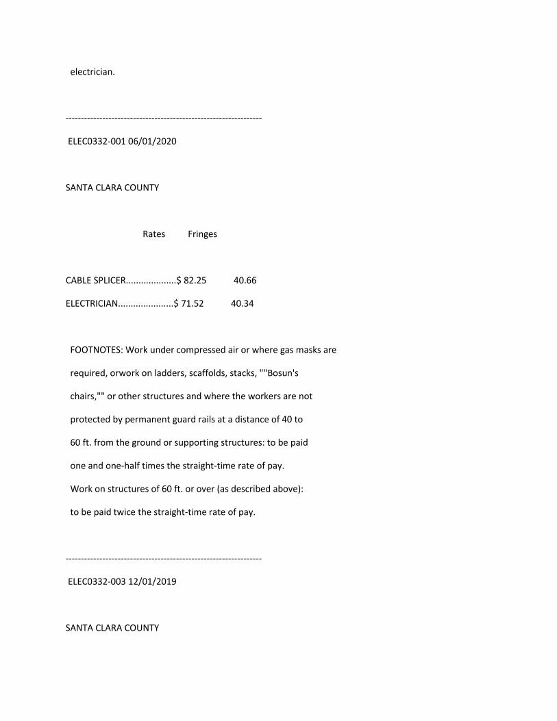
electrician.
----------------------------------------------------------------
ELEC0332-001 06/01/2020
SANTA CLARA COUNTY
Rates Fringes
CABLE SPLICER....................$ 82.25 40.66
ELECTRICIAN......................$ 71.52 40.34
FOOTNOTES: Work under compressed air or where gas masks are
required, orwork on ladders, scaffolds, stacks, ""Bosun's
chairs,"" or other structures and where the workers are not
protected by permanent guard rails at a distance of 40 to
60 ft. from the ground or supporting structures: to be paid
one and one-half times the straight-time rate of pay.
Work on structures of 60 ft. or over (as described above):
to be paid twice the straight-time rate of pay.
----------------------------------------------------------------
ELEC0332-003 12/01/2019
SANTA CLARA COUNTY
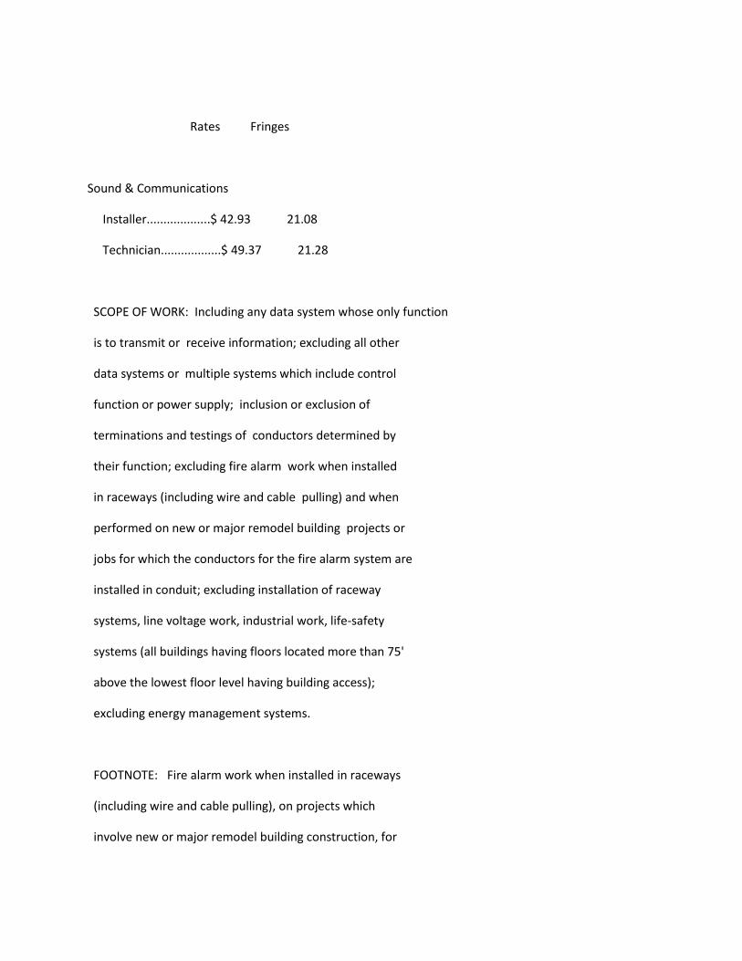
Rates Fringes
Sound & Communications
Installer...................$ 42.93 21.08
Technician..................$ 49.37 21.28
SCOPE OF WORK: Including any data system whose only function
is to transmit or receive information; excluding all other
data systems or multiple systems which include control
function or power supply; inclusion or exclusion of
terminations and testings of conductors determined by
their function; excluding fire alarm work when installed
in raceways (including wire and cable pulling) and when
performed on new or major remodel building projects or
jobs for which the conductors for the fire alarm system are
installed in conduit; excluding installation of raceway
systems, line voltage work, industrial work, life-safety
systems (all buildings having floors located more than 75'
above the lowest floor level having building access);
excluding energy management systems.
FOOTNOTE: Fire alarm work when installed in raceways
(including wire and cable pulling), on projects which
involve new or major remodel building construction, for
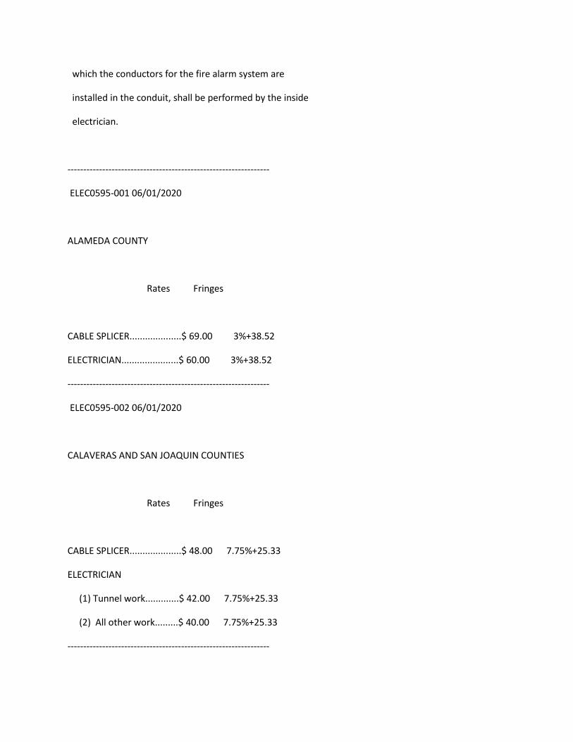
which the conductors for the fire alarm system are
installed in the conduit, shall be performed by the inside
electrician.
----------------------------------------------------------------
ELEC0595-001 06/01/2020
ALAMEDA COUNTY
Rates Fringes
CABLE SPLICER....................$ 69.00 3%+38.52
ELECTRICIAN......................$ 60.00 3%+38.52
----------------------------------------------------------------
ELEC0595-002 06/01/2020
CALAVERAS AND SAN JOAQUIN COUNTIES
Rates Fringes
CABLE SPLICER....................$ 48.00 7.75%+25.33
ELECTRICIAN
(1) Tunnel work.............$ 42.00 7.75%+25.33
(2) All other work.........$ 40.00 7.75%+25.33
----------------------------------------------------------------
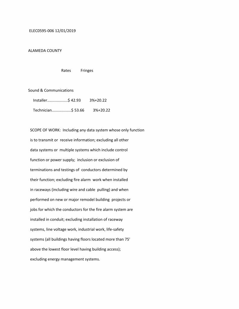
ELEC0595-006 12/01/2019
ALAMEDA COUNTY
Rates Fringes
Sound & Communications
Installer...................$ 42.93 3%+20.22
Technician..................$ 53.66 3%+20.22
SCOPE OF WORK: Including any data system whose only function
is to transmit or receive information; excluding all other
data systems or multiple systems which include control
function or power supply; inclusion or exclusion of
terminations and testings of conductors determined by
their function; excluding fire alarm work when installed
in raceways (including wire and cable pulling) and when
performed on new or major remodel building projects or
jobs for which the conductors for the fire alarm system are
installed in conduit; excluding installation of raceway
systems, line voltage work, industrial work, life-safety
systems (all buildings having floors located more than 75'
above the lowest floor level having building access);
excluding energy management systems.
FOOTNOTE: Fire alarm work when installed in raceways
(including wire and cable pulling), on projects which
involve new or major remodel building construction, for
which the conductors for the fire alarm system are
installed in the conduit, shall be performed by the inside
electrician.
----------------------------------------------------------------
ELEC0595-008 12/01/2019
CALAVERAS AND SAN JOAQUIN COUNTIES
Rates Fringes
Communications System
Installer...................$ 35.25 3%+20.22
Technician..................$ 44.06 3%+20.22
SCOPE OF WORK: Including any data system whose only function
is to transmit or receive information; excluding all other
data systems or multiple systems which include control
function or power supply; inclusion or exclusion of
terminations and testings of conductors determined by
their function; excluding fire alarm work when installed
in raceways (including wire and cable pulling) and when
performed on new or major remodel building projects or
jobs for which the conductors for the fire alarm system are
installed in conduit; excluding installation of raceway
systems, line voltage work, industrial work, life-safety
systems (all buildings having floors located more than 75'
above the lowest floor level having building access);
excluding energy management systems.
FOOTNOTE: Fire alarm work when installed in raceways
(including wire and cable pulling), on projects which
involve new or major remodel building construction, for
which the conductors for the fire alarm system are
installed in the conduit, shall be performed by the inside
electrician.
----------------------------------------------------------------
ELEC0617-001 06/01/2020
SAN MATEO COUNTY
Rates Fringes
ELECTRICIAN......................$ 66.00 39.77
----------------------------------------------------------------
ELEC0617-003 12/01/2019
SAN MATEO COUNTY
Rates Fringes
Sound & Communications
Installer...................$ 42.93 21.09
Technician..................$ 49.37 21.28
SCOPE OF WORK: Including any data system whose only function
is to transmit or receive information; excluding all other
data systems or multiple systems which include control
function or power supply; inclusion or exclusion of
terminations and testings of conductors determined by
their function; excluding fire alarm work when installed
in raceways (including wire and cable pulling) and when
performed on new or major remodel building projects or
jobs for which the conductors for the fire alarm system are
installed in conduit; excluding installation of raceway
systems, line voltage work, industrial work, life-safety
systems (all buildings having floors located more than 75'
above the lowest floor level having building access);
excluding energy management systems.
FOOTNOTE: Fire alarm work when installed in raceways
(including wire and cable pulling), on projects which
involve new or major remodel building construction, for
which the conductors for the fire alarm system are
installed in the conduit, shall be performed by the inside
electrician.
----------------------------------------------------------------
ELEC0684-001 06/01/2020
MARIPOSA, MERCED, STANISLAUS AND TUOLUMNE COUNTIES
Rates Fringes
ELECTRICIAN......................$ 41.00 3%+24.58
CABLE SPLICER = 110% of Journeyman Electrician
----------------------------------------------------------------
ELEC0684-004 12/01/2019
MARIPOSA, MERCED, STANISLAUS AND TUOLUMNE COUNTIES
Rates Fringes
Communications System
Installer...................$ 35.25 20.86
Technician..................$ 40.54 21.02
SCOPE OF WORK: Including any data system whose only function
is to transmit or receive information; excluding all other
data systems or multiple systems which include control
function or power supply; inclusion or exclusion of
terminations and testings of conductors determined by
their function; excluding fire alarm work when installed
in raceways (including wire and cable pulling) and when
performed on new or major remodel building projects or
jobs for which the conductors for the fire alarm system are
installed in conduit; excluding installation of raceway
systems, line voltage work, industrial work, life-safety
systems (all buildings having floors located more than 75'
above the lowest floor level having building access);
excluding energy management systems.
FOOTNOTE: Fire alarm work when installed in raceways
(including wire and cable pulling), on projects which
involve new or major remodel building construction, for
which the conductors for the fire alarm system are
installed in the conduit, shall be performed by the inside
electrician.
----------------------------------------------------------------
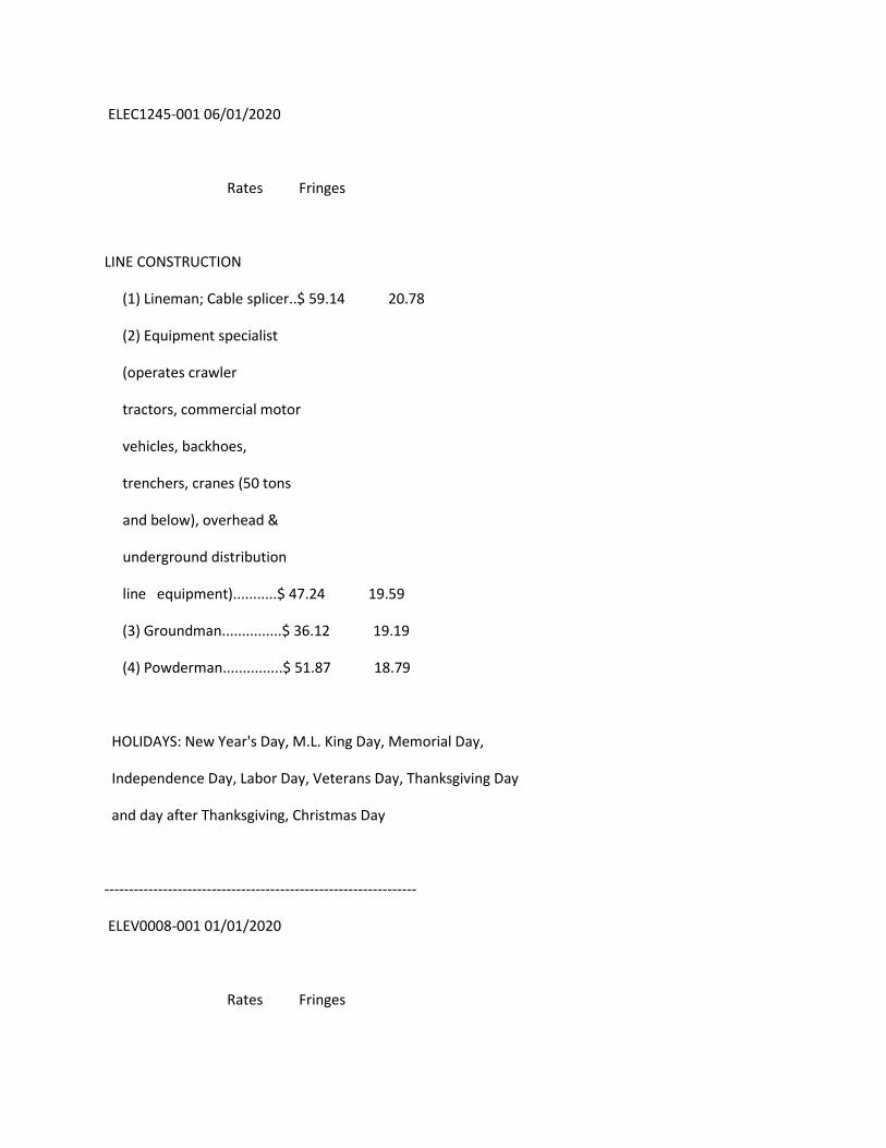
ELEC1245-001 06/01/2020
Rates Fringes
LINE CONSTRUCTION
(1) Lineman; Cable splicer..$ 59.14 20.78
(2) Equipment specialist
(operates crawler
tractors, commercial motor
vehicles, backhoes,
trenchers, cranes (50 tons
and below), overhead &
underground distribution
line equipment)...........$ 47.24 19.59
(3) Groundman...............$ 36.12 19.19
(4) Powderman...............$ 51.87 18.79
HOLIDAYS: New Year's Day, M.L. King Day, Memorial Day,
Independence Day, Labor Day, Veterans Day, Thanksgiving Day
and day after Thanksgiving, Christmas Day
----------------------------------------------------------------
ELEV0008-001 01/01/2020
Rates Fringes
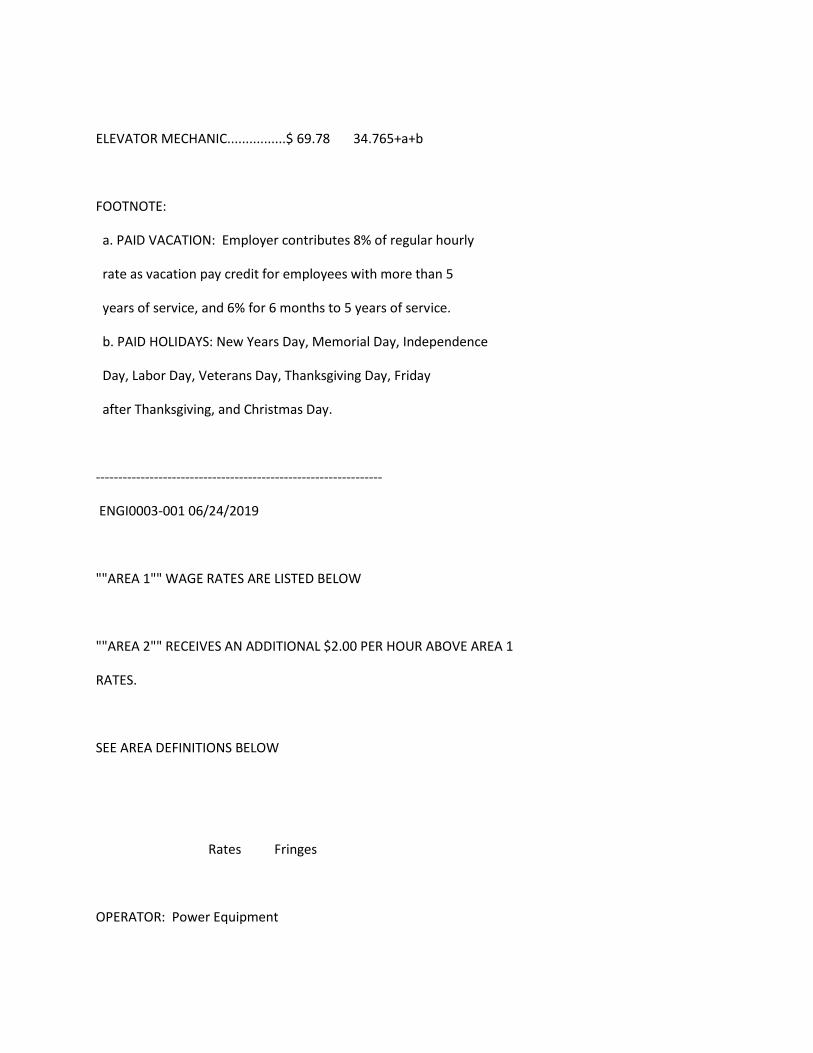
ELEVATOR MECHANIC................$ 69.78 34.765+a+b
FOOTNOTE:
a. PAID VACATION: Employer contributes 8% of regular hourly
rate as vacation pay credit for employees with more than 5
years of service, and 6% for 6 months to 5 years of service.
b. PAID HOLIDAYS: New Years Day, Memorial Day, Independence
Day, Labor Day, Veterans Day, Thanksgiving Day, Friday
after Thanksgiving, and Christmas Day.
----------------------------------------------------------------
ENGI0003-001 06/24/2019
""AREA 1"" WAGE RATES ARE LISTED BELOW
""AREA 2"" RECEIVES AN ADDITIONAL $2.00 PER HOUR ABOVE AREA 1
RATES.
SEE AREA DEFINITIONS BELOW
Rates Fringes
OPERATOR: Power Equipment
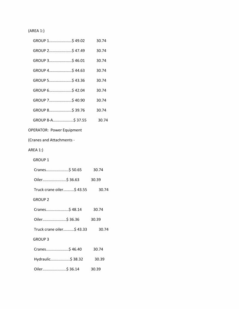
(AREA 1:)
GROUP 1.....................$ 49.02 30.74
GROUP 2.....................$ 47.49 30.74
GROUP 3.....................$ 46.01 30.74
GROUP 4.....................$ 44.63 30.74
GROUP 5.....................$ 43.36 30.74
GROUP 6.....................$ 42.04 30.74
GROUP 7.....................$ 40.90 30.74
GROUP 8.....................$ 39.76 30.74
GROUP 8-A...................$ 37.55 30.74
OPERATOR: Power Equipment
(Cranes and Attachments -
AREA 1:)
GROUP 1
Cranes.....................$ 50.65 30.74
Oiler......................$ 36.63 30.39
Truck crane oiler..........$ 43.55 30.74
GROUP 2
Cranes.....................$ 48.14 30.74
Oiler......................$ 36.36 30.39
Truck crane oiler..........$ 43.33 30.74
GROUP 3
Cranes.....................$ 46.40 30.74
Hydraulic..................$ 38.32 30.39
Oiler......................$ 36.14 30.39
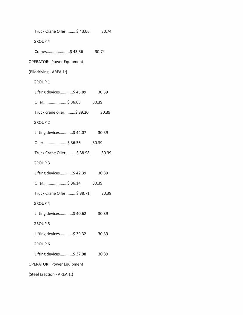
Truck Crane Oiler..........$ 43.06 30.74
GROUP 4
Cranes.....................$ 43.36 30.74
OPERATOR: Power Equipment
(Piledriving - AREA 1:)
GROUP 1
Lifting devices............$ 45.89 30.39
Oiler......................$ 36.63 30.39
Truck crane oiler..........$ 39.20 30.39
GROUP 2
Lifting devices............$ 44.07 30.39
Oiler......................$ 36.36 30.39
Truck Crane Oiler..........$ 38.98 30.39
GROUP 3
Lifting devices............$ 42.39 30.39
Oiler......................$ 36.14 30.39
Truck Crane Oiler..........$ 38.71 30.39
GROUP 4
Lifting devices............$ 40.62 30.39
GROUP 5
Lifting devices............$ 39.32 30.39
GROUP 6
Lifting devices............$ 37.98 30.39
OPERATOR: Power Equipment
(Steel Erection - AREA 1:)
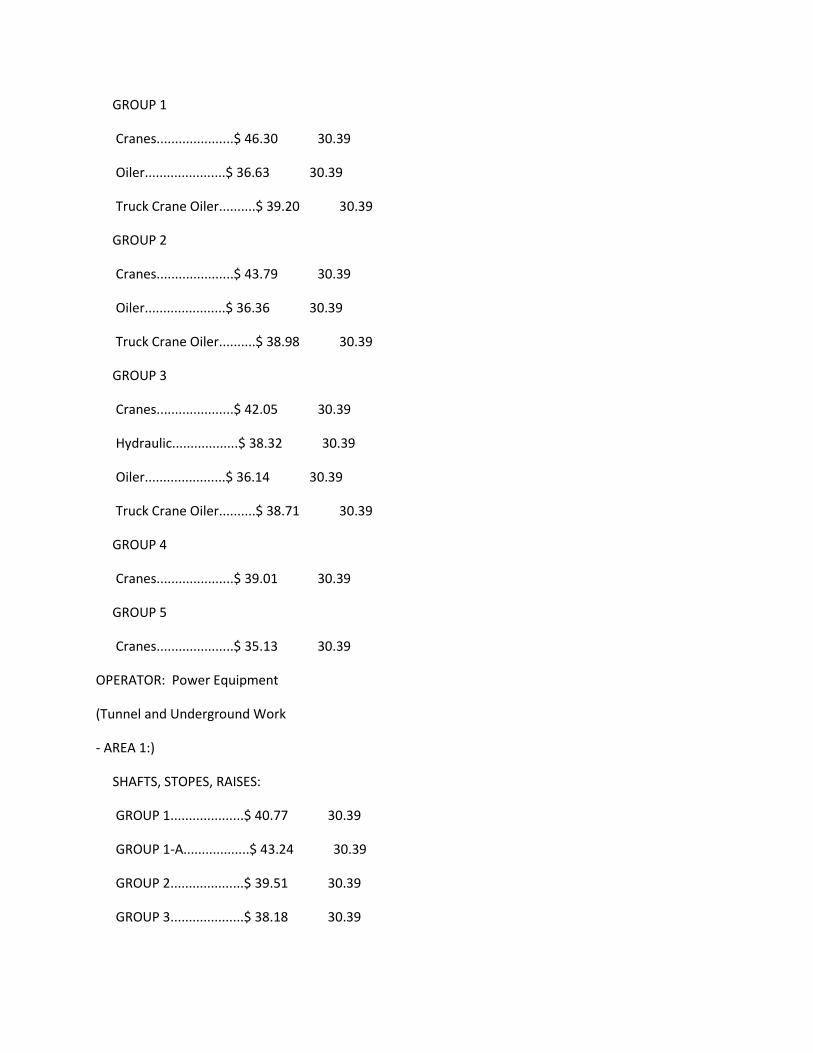
GROUP 1
Cranes.....................$ 46.30 30.39
Oiler......................$ 36.63 30.39
Truck Crane Oiler..........$ 39.20 30.39
GROUP 2
Cranes.....................$ 43.79 30.39
Oiler......................$ 36.36 30.39
Truck Crane Oiler..........$ 38.98 30.39
GROUP 3
Cranes.....................$ 42.05 30.39
Hydraulic..................$ 38.32 30.39
Oiler......................$ 36.14 30.39
Truck Crane Oiler..........$ 38.71 30.39
GROUP 4
Cranes.....................$ 39.01 30.39
GROUP 5
Cranes.....................$ 35.13 30.39
OPERATOR: Power Equipment
(Tunnel and Underground Work
- AREA 1:)
SHAFTS, STOPES, RAISES:
GROUP 1....................$ 40.77 30.39
GROUP 1-A..................$ 43.24 30.39
GROUP 2....................$ 39.51 30.39
GROUP 3....................$ 38.18 30.39

GROUP 4....................$ 37.04 30.39
GROUP 5....................$ 35.90 30.39
UNDERGROUND:
GROUP 1....................$ 40.67 30.39
GROUP 1-A..................$ 43.14 30.39
GROUP 2....................$ 39.41 30.39
GROUP 3....................$ 38.08 30.39
GROUP 4....................$ 36.94 30.39
GROUP 5....................$ 35.80 30.39
FOOTNOTE: Work suspended by ropes or cables, or work on a
Yo-Yo Cat: $.60 per hour additional.
POWER EQUIPMENT OPERATOR CLASSIFICATIONS
GROUP 1: Operator of helicopter (when used in erection work);
Hydraulic excavator, 7 cu. yds. and over; Power shovels,
over 7 cu. yds.
GROUP 2: Highline cableway; Hydraulic excavator, 3-1/2 cu.
yds. up to 7 cu. yds.; Licensed construction work boat
operator, on site; Power blade operator (finish); Power
shovels, over 1 cu. yd. up to and including 7 cu. yds.
m.r.c.
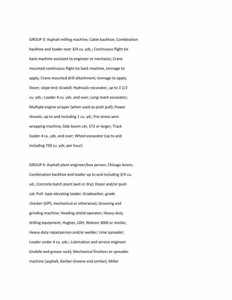
GROUP 3: Asphalt milling machine; Cable backhoe; Combination
backhoe and loader over 3/4 cu. yds.; Continuous flight tie
back machine assistant to engineer or mechanic; Crane
mounted continuous flight tie back machine, tonnage to
apply; Crane mounted drill attachment, tonnage to apply;
Dozer, slope brd; Gradall; Hydraulic excavator, up to 3 1/2
cu. yds.; Loader 4 cu. yds. and over; Long reach excavator;
Multiple engine scraper (when used as push pull); Power
shovels, up to and including 1 cu. yd.; Pre-stress wire
wrapping machine; Side boom cat, 572 or larger; Track
loader 4 cu. yds. and over; Wheel excavator (up to and
including 750 cu. yds. per hour)
GROUP 4: Asphalt plant engineer/box person; Chicago boom;
Combination backhoe and loader up to and including 3/4 cu.
yd.; Concrete batch plant (wet or dry); Dozer and/or push
cat; Pull- type elevating loader; Gradesetter, grade
checker (GPS, mechanical or otherwise); Grooving and
grinding machine; Heading shield operator; Heavy-duty
drilling equipment, Hughes, LDH, Watson 3000 or similar;
Heavy-duty repairperson and/or welder; Lime spreader;
Loader under 4 cu. yds.; Lubrication and service engineer
(mobile and grease rack); Mechanical finishers or spreader
machine (asphalt, Barber-Greene and similar); Miller

Formless M-9000 slope paver or similar; Portable crushing
and screening plants; Power blade support; Roller operator,
asphalt; Rubber-tired scraper, self-loading (paddle-wheels,
etc.); Rubber- tired earthmoving equipment (scrapers); Slip
form paver (concrete); Small tractor with drag; Soil
stabilizer (P & H or equal); Spider plow and spider puller;
Tubex pile rig; Unlicensed constuction work boat operator,
on site; Timber skidder; Track loader up to 4 yds.;
Tractor-drawn scraper; Tractor, compressor drill
combination; Welder; Woods-Mixer (and other similar Pugmill
equipment)
GROUP 5: Cast-in-place pipe laying machine; Combination
slusher and motor operator; Concrete conveyor or concrete
pump, truck or equipment mounted; Concrete conveyor,
building site; Concrete pump or pumpcrete gun; Drilling
equipment, Watson 2000, Texoma 700 or similar; Drilling and
boring machinery, horizontal (not to apply to waterliners,
wagon drills or jackhammers); Concrete mixer/all; Person
and/or material hoist; Mechanical finishers (concrete)
(Clary, Johnson, Bidwell Bridge Deck or similar types);
Mechanical burm, curb and/or curb and gutter machine,
concrete or asphalt); Mine or shaft hoist; Portable
crusher; Power jumbo operator (setting slip-forms, etc., in
tunnels); Screed (automatic or manual); Self-propelled
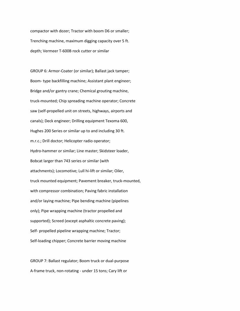
compactor with dozer; Tractor with boom D6 or smaller;
Trenching machine, maximum digging capacity over 5 ft.
depth; Vermeer T-600B rock cutter or similar
GROUP 6: Armor-Coater (or similar); Ballast jack tamper;
Boom- type backfilling machine; Assistant plant engineer;
Bridge and/or gantry crane; Chemical grouting machine,
truck-mounted; Chip spreading machine operator; Concrete
saw (self-propelled unit on streets, highways, airports and
canals); Deck engineer; Drilling equipment Texoma 600,
Hughes 200 Series or similar up to and including 30 ft.
m.r.c.; Drill doctor; Helicopter radio operator;
Hydro-hammer or similar; Line master; Skidsteer loader,
Bobcat larger than 743 series or similar (with
attachments); Locomotive; Lull hi-lift or similar; Oiler,
truck mounted equipment; Pavement breaker, truck-mounted,
with compressor combination; Paving fabric installation
and/or laying machine; Pipe bending machine (pipelines
only); Pipe wrapping machine (tractor propelled and
supported); Screed (except asphaltic concrete paving);
Self- propelled pipeline wrapping machine; Tractor;
Self-loading chipper; Concrete barrier moving machine
GROUP 7: Ballast regulator; Boom truck or dual-purpose
A-frame truck, non-rotating - under 15 tons; Cary lift or
similar; Combination slurry mixer and/or cleaner; Drilling
equipment, 20 ft. and under m.r.c.; Firetender (hot plant);
Grouting machine operator; Highline cableway signalperson;
Stationary belt loader (Kolman or similar); Lift slab
machine (Vagtborg and similar types); Maginnes internal
full slab vibrator; Material hoist (1 drum); Mechanical
trench shield; Pavement breaker with or without compressor
combination); Pipe cleaning machine (tractor propelled and
supported); Post driver; Roller (except asphalt); Chip
Seal; Self-propelled automatically applied concrete curing
mahcine (on streets, highways, airports and canals);
Self-propelled compactor (without dozer); Signalperson;
Slip-form pumps (lifting device for concrete forms); Tie
spacer; Tower mobile; Trenching machine, maximum digging
capacity up to and including 5 ft. depth; Truck- type loader
GROUP 8: Bit sharpener; Boiler tender; Box operator;
Brakeperson; Combination mixer and compressor
(shotcrete/gunite); Compressor operator; Deckhand; Fire
tender; Forklift (under 20 ft.); Generator;
Gunite/shotcrete equipment operator; Hydraulic monitor; Ken
seal machine (or similar); Mixermobile; Oiler; Pump
operator; Refrigeration plant; Reservoir-debris tug (self-
propelled floating); Ross Carrier (construction site);
Rotomist operator; Self-propelled tape machine; Shuttlecar;
Self-propelled power sweeper operator (includes vacuum
sweeper); Slusher operator; Surface heater; Switchperson;
Tar pot firetender; Tugger hoist, single drum; Vacuum
cooling plant; Welding machine (powered other than by
electricity)
GROUP 8-A: Elevator operator; Skidsteer loader-Bobcat 743
series or smaller, and similar (without attachments); Mini
excavator under 25 H.P. (backhoe-trencher); Tub grinder
wood chipper
----------------------------------------------------------
ALL CRANES AND ATTACHMENTS
GROUP 1: Clamshell and dragline over 7 cu. yds.; Crane, over
100 tons; Derrick, over 100 tons; Derrick barge
pedestal-mounted, over 100 tons; Self-propelled boom-type
lifting device, over 100 tons
GROUP 2: Clamshell and dragline over 1 cu. yd. up to and
including 7 cu. yds.; Crane, over 45 tons up to and
including 100 tons; Derrick barge, 100 tons and under;
Self-propelled boom-type lifting device, over 45 tons;
Tower crane
GROUP 3: Clamshell and dragline up to and including 1 cu.
yd.; Cranes 45 tons and under; Self-propelled boom-type
lifting device 45 tons and under;
GROUP 4: Boom Truck or dual purpose A-frame truck,
non-rotating over 15 tons; Truck-mounted rotating
telescopic boom type lifting device, Manitex or similar
(boom truck) over 15 tons; Truck-mounted rotating
telescopic boom type lifting device, Manitex or similar
(boom truck) - under 15 tons;
-----------------------------------------------------------
PILEDRIVERS
GROUP 1: Derrick barge pedestal mounted over 100 tons;
Clamshell over 7 cu. yds.; Self-propelled boom-type lifting
device over 100 tons; Truck crane or crawler, land or barge
mounted over 100 tons
GROUP 2: Derrick barge pedestal mounted 45 tons to and
including 100 tons; Clamshell up to and including 7 cu.
yds.; Self-propelled boom-type lifting device over 45 tons;
Truck crane or crawler, land or barge mounted, over 45 tons
up to and including 100 tons; Fundex F-12 hydraulic pile rig
GROUP 3: Derrick barge pedestal mounted under 45 tons; Self-
propelled boom-type lifting device 45 tons and under;
Skid/scow piledriver, any tonnage; Truck crane or crawler,
land or barge mounted 45 tons and under
GROUP 4: Assistant operator in lieu of assistant to engineer;
Forklift, 10 tons and over; Heavy-duty repairperson/welder
GROUP 5: Deck engineer
GROUP 6: Deckhand; Fire tender
-------------------------------------------------------------
STEEL ERECTORS
GROUP 1: Crane over 100 tons; Derrick over 100 tons; Self-
propelled boom-type lifting device over 100 tons
GROUP 2: Crane over 45 tons to 100 tons; Derrick under 100
tons; Self-propelled boom-type lifting device over 45 tons
to 100 tons; Tower crane
GROUP 3: Crane, 45 tons and under; Self-propelled boom-type
lifting device, 45 tons and under
GROUP 4: Chicago boom; Forklift, 10 tons and over; Heavy-duty
repair person/welder
GROUP 5: Boom cat
--------------------------------------------------------------
--
TUNNEL AND UNDERGROUND WORK
GROUP 1-A: Tunnel bore machine operator, 20' diameter or more
GROUP 1: Heading shield operator; Heavy-duty repairperson;
Mucking machine (rubber tired, rail or track type); Raised
bore operator (tunnels); Tunnel mole bore operator
GROUP 2: Combination slusher and motor operator; Concrete
pump or pumpcrete gun; Power jumbo operator
GROUP 3: Drill doctor; Mine or shaft hoist
GROUP 4: Combination slurry mixer cleaner; Grouting Machine
operator; Motorman
GROUP 5: Bit Sharpener; Brakeman; Combination mixer and
compressor (gunite); Compressor operator; Oiler; Pump
operator; Slusher operator
-----------------------------------------------------------
AREA DESCRIPTIONS:
POWER EQUIPMENT OPERATORS, CRANES AND ATTACHMENTS,TUNNEL AND
UNDERGROUND [These areas do not apply to Piledrivers and
Steel Erectors]
AREA 1: ALAMEDA, CALAVERAS, CONTRA COSTA, FRESNO, KINGS,
MADERA, MARIPOSA, MERCED, MONTEREY, SAN BENITO, SAN
FRANCISCO, SAN JOAQUIN, SAN MATEO, SANTA CLARA, SANTA CRUZ,
STANISLAUS, TUOLUMNE
AREA 2 -NOTED BELOW
THE REMAINING COUNTIES ARE SPLIT BETWEEN AREA 1 AND AREA 2 AS
NOTED BELOW:
CALAVERAS COUNTY:
Area 1: Remainder
Area 2: Eastern Part
FRESNO COUNTY:
Area 1: Remainder
Area 2: Eastern Part
MADERA COUNTY:
Area 1: Remainder
Area 2: Eastern Part
MARIPOSA COUNTY:
Area 1: Remainder
Area 2: Eastern Part
MONTEREY COUNTY:
Area 1: Remainder
Area 2: Southwestern part
TUOLUMNE COUNTY:
Area 1: Remainder
Area 2: Eastern Part
----------------------------------------------------------------
ENGI0003-008 07/01/2019
Rates Fringes
Dredging: (DREDGING:
CLAMSHELL & DIPPER DREDGING;
HYDRAULIC SUCTION DREDGING:)
AREA 1:
(1) Leverman...............$ 47.88 33.10
(2) Dredge Dozer; Heavy
duty repairman.............$ 42.92 33.10
(3) Booster Pump
Operator; Deck
Engineer; Deck mate;
Dredge Tender; Winch
Operator...................$ 41.80 33.10
(4) Bargeman; Deckhand;
Fireman; Leveehand; Oiler..$ 38.50 33.10
AREA 2:
(1) Leverman...............$ 49.88 33.10
(2) Dredge Dozer; Heavy
duty repairman.............$ 44.92 33.10
(3) Booster Pump
Operator; Deck
Engineer; Deck mate;
Dredge Tender; Winch
Operator...................$ 43.80 33.10
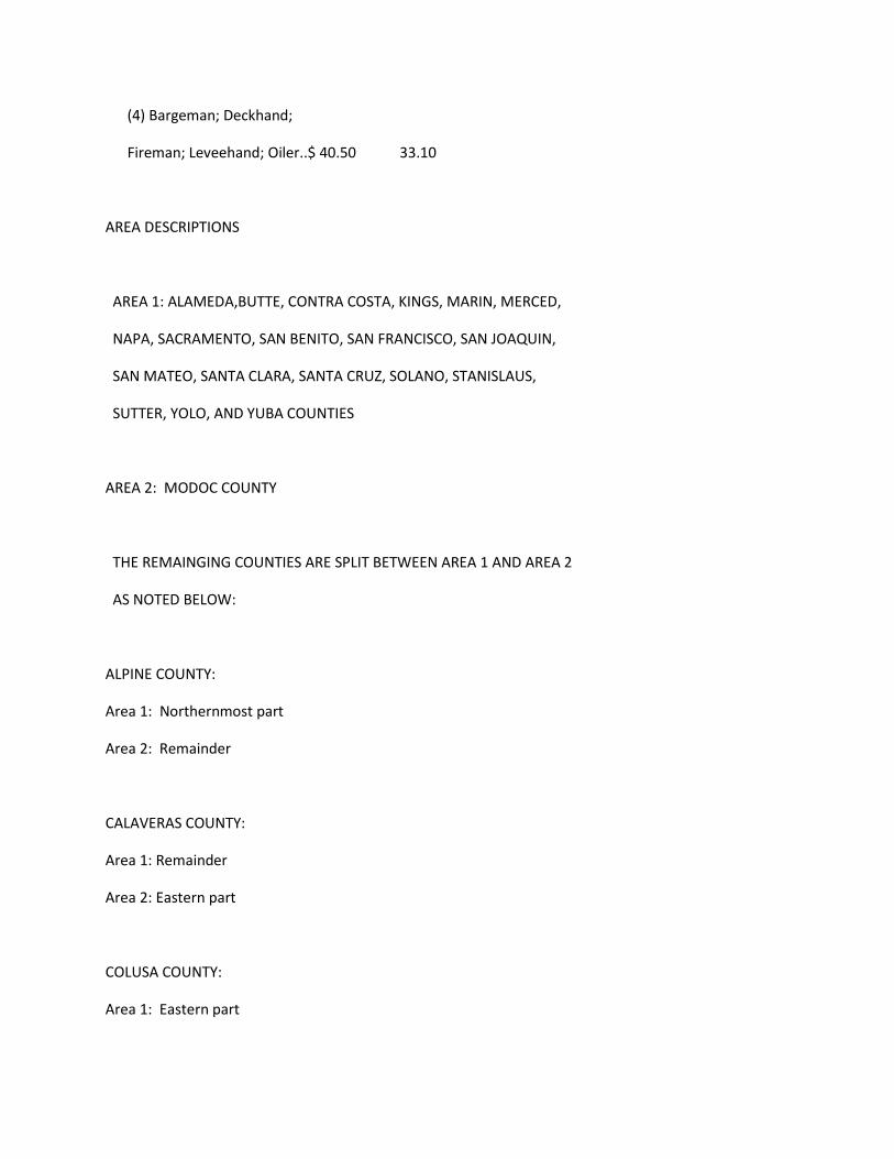
(4) Bargeman; Deckhand;
Fireman; Leveehand; Oiler..$ 40.50 33.10
AREA DESCRIPTIONS
AREA 1: ALAMEDA,BUTTE, CONTRA COSTA, KINGS, MARIN, MERCED,
NAPA, SACRAMENTO, SAN BENITO, SAN FRANCISCO, SAN JOAQUIN,
SAN MATEO, SANTA CLARA, SANTA CRUZ, SOLANO, STANISLAUS,
SUTTER, YOLO, AND YUBA COUNTIES
AREA 2: MODOC COUNTY
THE REMAINGING COUNTIES ARE SPLIT BETWEEN AREA 1 AND AREA 2
AS NOTED BELOW:
ALPINE COUNTY:
Area 1: Northernmost part
Area 2: Remainder
CALAVERAS COUNTY:
Area 1: Remainder
Area 2: Eastern part
COLUSA COUNTY:
Area 1: Eastern part
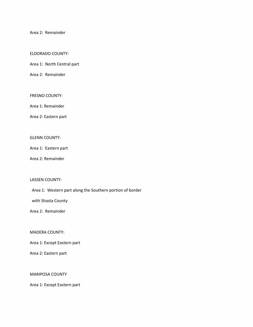
Area 2: Remainder
ELDORADO COUNTY:
Area 1: North Central part
Area 2: Remainder
FRESNO COUNTY:
Area 1: Remainder
Area 2: Eastern part
GLENN COUNTY:
Area 1: Eastern part
Area 2: Remainder
LASSEN COUNTY:
Area 1: Western part along the Southern portion of border
with Shasta County
Area 2: Remainder
MADERA COUNTY:
Area 1: Except Eastern part
Area 2: Eastern part
MARIPOSA COUNTY
Area 1: Except Eastern part
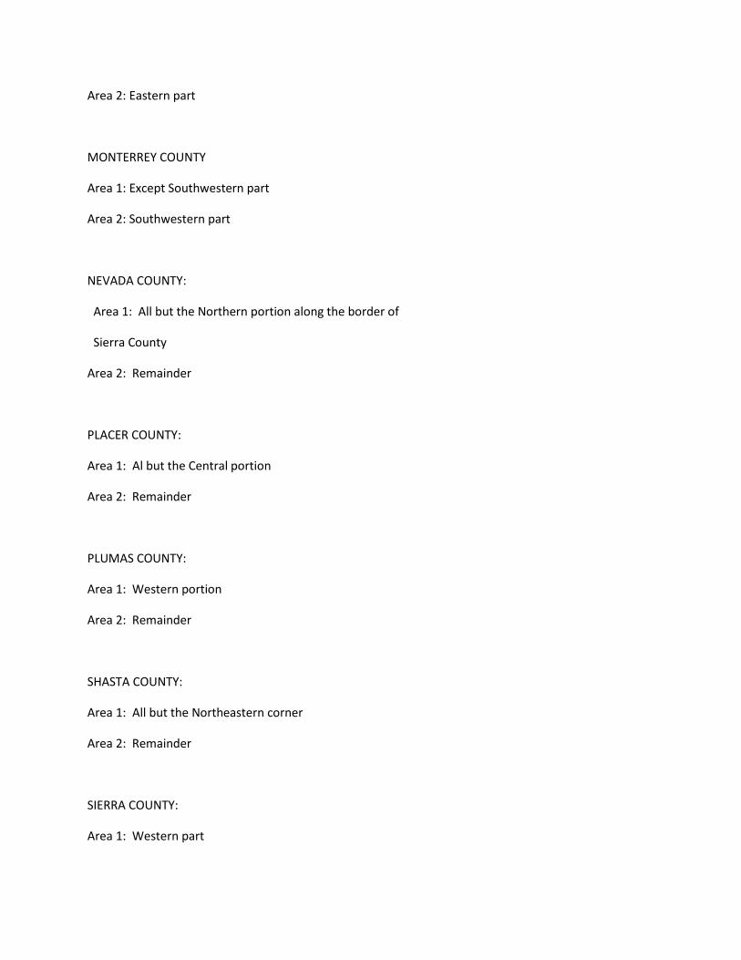
Area 2: Eastern part
MONTERREY COUNTY
Area 1: Except Southwestern part
Area 2: Southwestern part
NEVADA COUNTY:
Area 1: All but the Northern portion along the border of
Sierra County
Area 2: Remainder
PLACER COUNTY:
Area 1: Al but the Central portion
Area 2: Remainder
PLUMAS COUNTY:
Area 1: Western portion
Area 2: Remainder
SHASTA COUNTY:
Area 1: All but the Northeastern corner
Area 2: Remainder
SIERRA COUNTY:
Area 1: Western part

Area 2: Remainder
SISKIYOU COUNTY:
Area 1: Central part
Area 2: Remainder
SONOMA COUNTY:
Area 1: All but the Northwestern corner
Area 2: Remainder
TEHAMA COUNTY:
Area 1: All but the Western border with Mendocino & Trinity
Counties
Area 2: Remainder
TRINITY COUNTY:
Area 1: East Central part and the Northeastern border with
Shasta County
Area 2: Remainder
TUOLUMNE COUNTY:
Area 1: Except Eastern part
Area 2: Eastern part
----------------------------------------------------------------
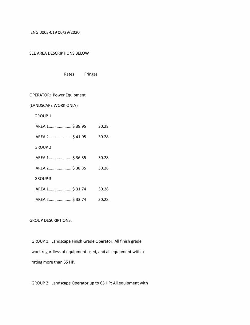
ENGI0003-019 06/29/2020
SEE AREA DESCRIPTIONS BELOW
Rates Fringes
OPERATOR: Power Equipment
(LANDSCAPE WORK ONLY)
GROUP 1
AREA 1.....................$ 39.95 30.28
AREA 2.....................$ 41.95 30.28
GROUP 2
AREA 1.....................$ 36.35 30.28
AREA 2.....................$ 38.35 30.28
GROUP 3
AREA 1.....................$ 31.74 30.28
AREA 2.....................$ 33.74 30.28
GROUP DESCRIPTIONS:
GROUP 1: Landscape Finish Grade Operator: All finish grade
work regardless of equipment used, and all equipment with a
rating more than 65 HP.
GROUP 2: Landscape Operator up to 65 HP: All equipment with

a manufacturer's rating of 65 HP or less except equipment
covered by Group 1 or Group 3. The following equipment
shall be included except when used for finish work as long
as manufacturer's rating is 65 HP or less: A-Frame and
Winch Truck, Backhoe, Forklift, Hydragraphic Seeder
Machine, Roller, Rubber-Tired and Track Earthmoving
Equipment, Skiploader, Straw Blowers, and Trencher 31 HP up
to 65 HP.
GROUP 3: Landscae Utility Operator: Small Rubber-Tired
Tractor, Trencher Under 31 HP.
AREA DESCRIPTIONS:
AREA 1: ALAMEDA, BUTTE, CONTRA COSTA, KINGS, MARIN, MERCED,
NAPA, SACRAMENTO, SAN BENITO, SAN FRANCISCO, SAN JOAQUIN,
SAN MATEO, SANTA CLARA, SANTA CRUZ, SOLANO, STANISLAUS,
SUTTER, YOLO, AND YUBA COUNTIES
AREA 2 - MODOC COUNTY
THE REMAINING COUNTIES ARE SPLIT BETWEEN AREA 1 AND AREA 2 AS
NOTED BELOW:
ALPINE COUNTY:
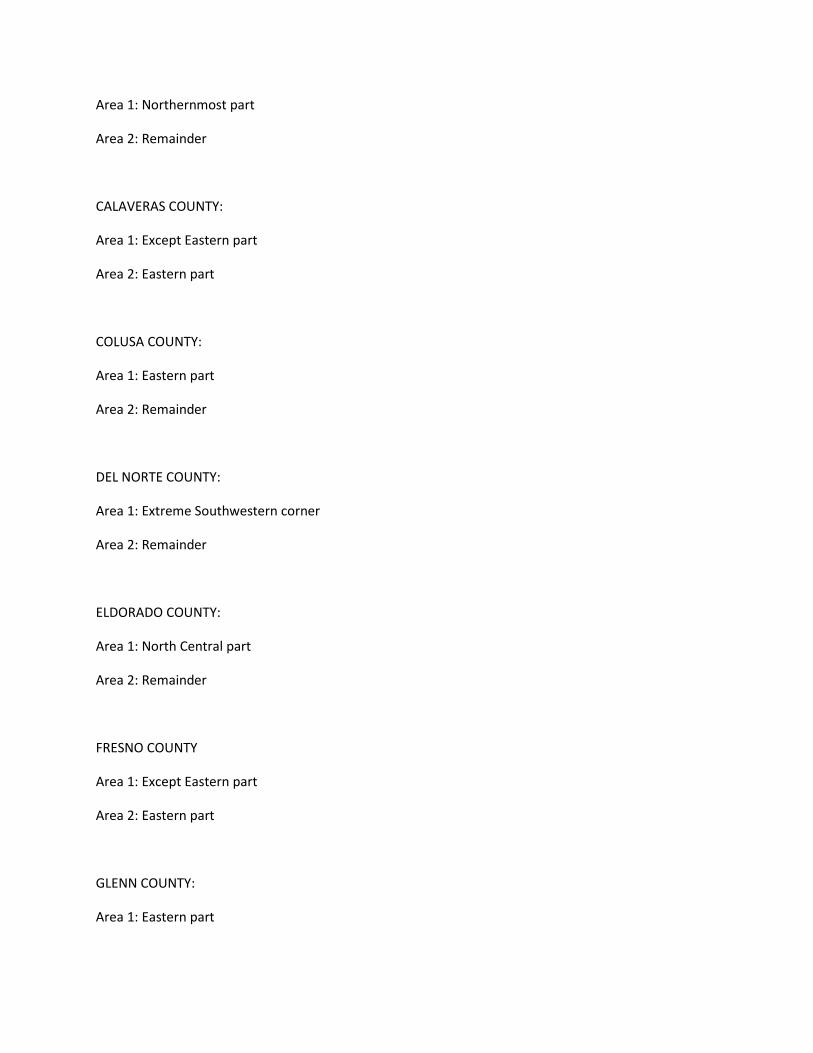
Area 1: Northernmost part
Area 2: Remainder
CALAVERAS COUNTY:
Area 1: Except Eastern part
Area 2: Eastern part
COLUSA COUNTY:
Area 1: Eastern part
Area 2: Remainder
DEL NORTE COUNTY:
Area 1: Extreme Southwestern corner
Area 2: Remainder
ELDORADO COUNTY:
Area 1: North Central part
Area 2: Remainder
FRESNO COUNTY
Area 1: Except Eastern part
Area 2: Eastern part
GLENN COUNTY:
Area 1: Eastern part
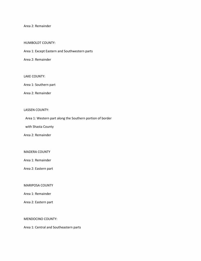
Area 2: Remainder
HUMBOLDT COUNTY:
Area 1: Except Eastern and Southwestern parts
Area 2: Remainder
LAKE COUNTY:
Area 1: Southern part
Area 2: Remainder
LASSEN COUNTY:
Area 1: Western part along the Southern portion of border
with Shasta County
Area 2: Remainder
MADERA COUNTY
Area 1: Remainder
Area 2: Eastern part
MARIPOSA COUNTY
Area 1: Remainder
Area 2: Eastern part
MENDOCINO COUNTY:
Area 1: Central and Southeastern parts

Area 2: Remainder
MONTEREY COUNTY
Area 1: Remainder
Area 2: Southwestern part
NEVADA COUNTY:
Area 1: All but the Northern portion along the border of
Sierra County
Area 2: Remainder
PLACER COUNTY:
Area 1: All but the Central portion
Area 2: Remainder
PLUMAS COUNTY:
Area 1: Western portion
Area 2: Remainder
SHASTA COUNTY:
Area 1: All but the Northeastern corner
Area 2: Remainder
SIERRA COUNTY:
Area 1: Western part

Area 2: Remainder
SISKIYOU COUNTY:
Area 1: Central part
Area 2: Remainder
SONOMA COUNTY:
Area 1: All but the Northwestern corner
Area 2: Reaminder
TEHAMA COUNTY:
Area 1: All but the Western border with mendocino & Trinity
Counties
Area 2: Remainder
TRINITY COUNTY:
Area 1: East Central part and the Northeaster border with
Shasta County
Area 2: Remainder
TULARE COUNTY;
Area 1: Remainder
Area 2: Eastern part
TUOLUMNE COUNTY:
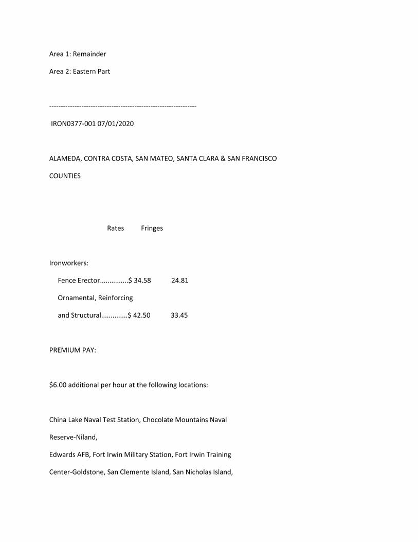
Area 1: Remainder
Area 2: Eastern Part
----------------------------------------------------------------
IRON0377-001 07/01/2020
ALAMEDA, CONTRA COSTA, SAN MATEO, SANTA CLARA & SAN FRANCISCO
COUNTIES
Rates Fringes
Ironworkers:
Fence Erector...............$ 34.58 24.81
Ornamental, Reinforcing
and Structural..............$ 42.50 33.45
PREMIUM PAY:
$6.00 additional per hour at the following locations:
China Lake Naval Test Station, Chocolate Mountains Naval
Reserve-Niland,
Edwards AFB, Fort Irwin Military Station, Fort Irwin Training
Center-Goldstone, San Clemente Island, San Nicholas Island,
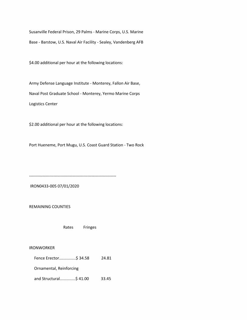
Susanville Federal Prison, 29 Palms - Marine Corps, U.S. Marine
Base - Barstow, U.S. Naval Air Facility - Sealey, Vandenberg AFB
$4.00 additional per hour at the following locations:
Army Defense Language Institute - Monterey, Fallon Air Base,
Naval Post Graduate School - Monterey, Yermo Marine Corps
Logistics Center
$2.00 additional per hour at the following locations:
Port Hueneme, Port Mugu, U.S. Coast Guard Station - Two Rock
----------------------------------------------------------------
IRON0433-005 07/01/2020
REMAINING COUNTIES
Rates Fringes
IRONWORKER
Fence Erector...............$ 34.58 24.81
Ornamental, Reinforcing
and Structural..............$ 41.00 33.45
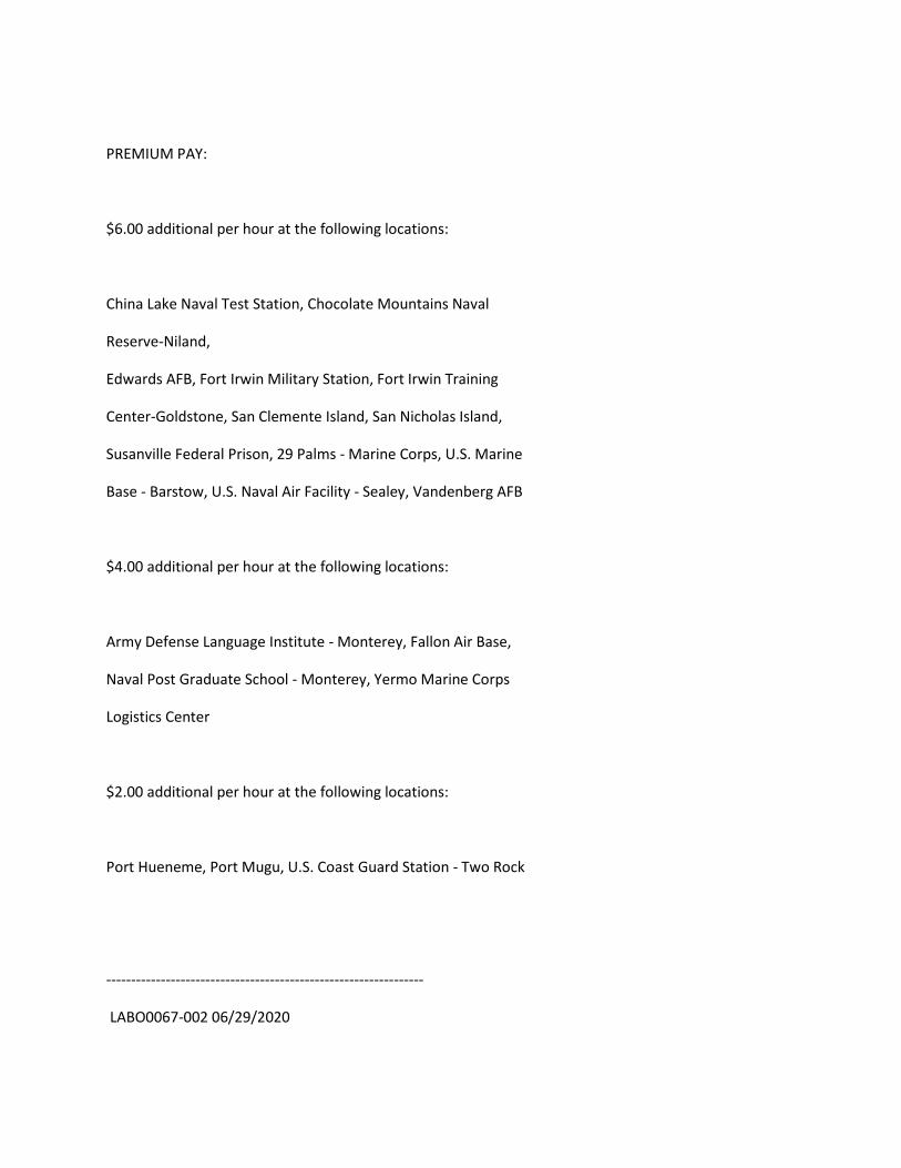
PREMIUM PAY:
$6.00 additional per hour at the following locations:
China Lake Naval Test Station, Chocolate Mountains Naval
Reserve-Niland,
Edwards AFB, Fort Irwin Military Station, Fort Irwin Training
Center-Goldstone, San Clemente Island, San Nicholas Island,
Susanville Federal Prison, 29 Palms - Marine Corps, U.S. Marine
Base - Barstow, U.S. Naval Air Facility - Sealey, Vandenberg AFB
$4.00 additional per hour at the following locations:
Army Defense Language Institute - Monterey, Fallon Air Base,
Naval Post Graduate School - Monterey, Yermo Marine Corps
Logistics Center
$2.00 additional per hour at the following locations:
Port Hueneme, Port Mugu, U.S. Coast Guard Station - Two Rock
----------------------------------------------------------------
LABO0067-002 06/29/2020
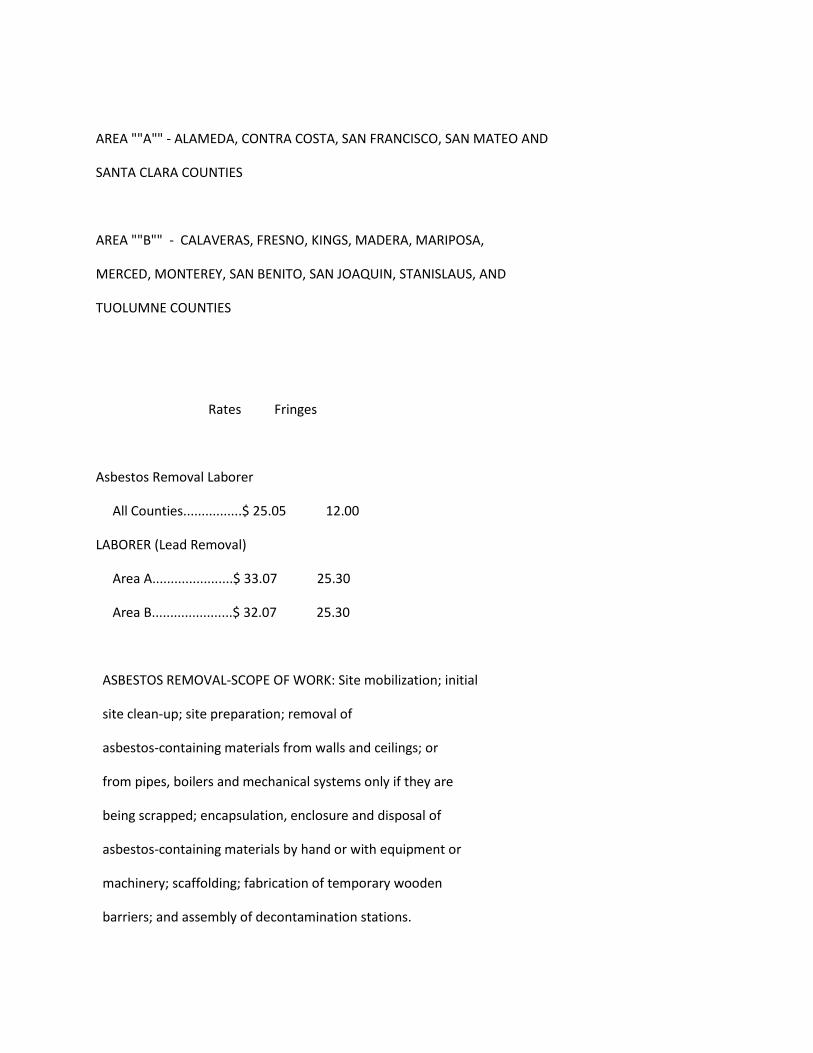
AREA ""A"" - ALAMEDA, CONTRA COSTA, SAN FRANCISCO, SAN MATEO AND
SANTA CLARA COUNTIES
AREA ""B"" - CALAVERAS, FRESNO, KINGS, MADERA, MARIPOSA,
MERCED, MONTEREY, SAN BENITO, SAN JOAQUIN, STANISLAUS, AND
TUOLUMNE COUNTIES
Rates Fringes
Asbestos Removal Laborer
All Counties................$ 25.05 12.00
LABORER (Lead Removal)
Area A......................$ 33.07 25.30
Area B......................$ 32.07 25.30
ASBESTOS REMOVAL-SCOPE OF WORK: Site mobilization; initial
site clean-up; site preparation; removal of
asbestos-containing materials from walls and ceilings; or
from pipes, boilers and mechanical systems only if they are
being scrapped; encapsulation, enclosure and disposal of
asbestos-containing materials by hand or with equipment or
machinery; scaffolding; fabrication of temporary wooden
barriers; and assembly of decontamination stations.
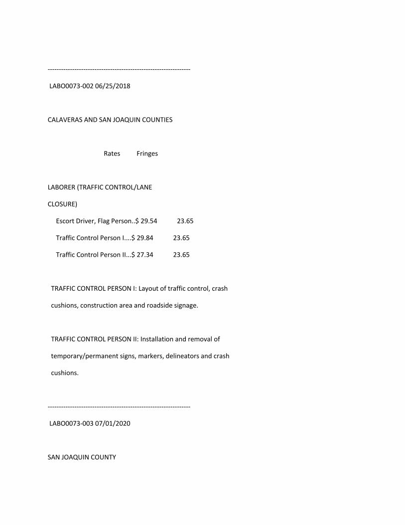
----------------------------------------------------------------
LABO0073-002 06/25/2018
CALAVERAS AND SAN JOAQUIN COUNTIES
Rates Fringes
LABORER (TRAFFIC CONTROL/LANE
CLOSURE)
Escort Driver, Flag Person..$ 29.54 23.65
Traffic Control Person I....$ 29.84 23.65
Traffic Control Person II...$ 27.34 23.65
TRAFFIC CONTROL PERSON I: Layout of traffic control, crash
cushions, construction area and roadside signage.
TRAFFIC CONTROL PERSON II: Installation and removal of
temporary/permanent signs, markers, delineators and crash
cushions.
----------------------------------------------------------------
LABO0073-003 07/01/2020
SAN JOAQUIN COUNTY
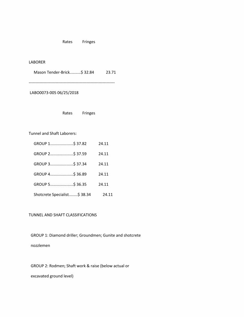
Rates Fringes
LABORER
Mason Tender-Brick..........$ 32.84 23.71
----------------------------------------------------------------
LABO0073-005 06/25/2018
Rates Fringes
Tunnel and Shaft Laborers:
GROUP 1.....................$ 37.82 24.11
GROUP 2.....................$ 37.59 24.11
GROUP 3.....................$ 37.34 24.11
GROUP 4.....................$ 36.89 24.11
GROUP 5.....................$ 36.35 24.11
Shotcrete Specialist........$ 38.34 24.11
TUNNEL AND SHAFT CLASSIFICATIONS
GROUP 1: Diamond driller; Groundmen; Gunite and shotcrete
nozzlemen
GROUP 2: Rodmen; Shaft work & raise (below actual or
excavated ground level)
GROUP 3: Bit grinder; Blaster, driller, powdermen, heading;
Cherry pickermen - where car is lifted; Concrete finisher
in tunnel; Concrete screedman; Grout pumpman and potman;
Gunite & shotcrete gunman & potman; Headermen; High
pressure nozzleman; Miner - tunnel, including top and
bottom man on shaft and raise work; Nipper; Nozzleman on
slick line; Sandblaster - potman, Robotic Shotcrete Placer,
Segment Erector, Tunnel Muck Hauler, Steel Form raiser and
setter; Timberman, retimberman (wood or steel or substitute
materials therefore); Tugger (for tunnel laborer work);
Cable tender; Chuck tender; Powderman - primer house
GROUP 4: Vibrator operator, pavement breaker; Bull gang -
muckers, trackmen; Concrete crew - includes rodding and
spreading, Dumpmen (any method)
GROUP 5: Grout crew; Reboundman; Swamper/ Brakeman
----------------------------------------------------------------
LABO0073-007 06/25/2018
CALAVERAS AND SAN JOAQUIN COUNTIES
Rates Fringes
LABORER (CONSTRUCTION CRAFT
LABORERS)
Construction Specialist
Group.......................$ 30.49 23.20
GROUP 1.....................$ 29.79 23.20
GROUP 1-a...................$ 30.01 23.20
GROUP 1-c...................$ 29.84 23.20
GROUP 1-e...................$ 30.34 23.20
GROUP 1-f...................$ 30.37 23.20
GROUP 2.....................$ 29.64 23.20
GROUP 3.....................$ 29.54 23.20
GROUP 4.....................$ 23.23 23.20
See groups 1-b and 1-d under laborer classifications.
LABORER (GARDENERS,
HORTICULTURAL & LANDSCAPE
LABORERS)
(1) New Construction........$ 29.54 23.20
(2) Establishment Warranty
Period......................$ 23.23 23.20
LABORER (GUNITE)
GROUP 1.....................$ 29.75 22.31
GROUP 2.....................$ 29.25 22.31
GROUP 3.....................$ 28.66 22.31
GROUP 4.....................$ 28.54 22.31
LABORER (WRECKING)
GROUP 1.....................$ 29.79 23.20
GROUP 2.....................$ 29.64 23.20
FOOTNOTES:
Laborers working off or with or from bos'n chairs, swinging
scaffolds, belts shall receive $0.25 per hour above the
applicable wage rate. This shall not apply to workers
entitled to receive the wage rate set forth in Group 1-a
below.
---------------------------------------------------------
LABORER CLASSIFICATIONS
CONSTRUCTION SPECIALIST GROUP: Asphalt ironer and raker;
Chainsaw; Laser beam in connection with laborers' work;
Cast-in- place manhole form setter; Pressure pipelayer;
Davis trencher - 300 or similar type (and all small
trenchers); Blaster; Diamond driller; Multiple unit drill;
Hydraulic drill
GROUP 1: Asphalt spreader boxes (all types); Barko, Wacker
and similar type tampers; Buggymobile; Caulker, bander,

pipewrapper, conduit layer, plastic pipelayer; Certified
hazardous waste worker including Leade Abatement;
Compactors of all types; Concrete and magnesite mixer, 1/2
yd. and under; Concrete pan work; Concrete sander; Concrete
saw; Cribber and/or shoring; Cut granite curb setter;
Dri-pak-it machine; Faller, logloader and bucker; Form
raiser, slip forms; Green cutter; Headerboard, Hubsetter,
aligner, by any method; High pressure blow pipe (1-1/2"" or
over, 100 lbs. pressure/over); Hydro seeder and similar
type; Jackhammer operator; Jacking of pipe over 12 inches;
Jackson and similar type compactor; Kettle tender, pot and
worker applying asphalt, lay-kold, creosote, lime, caustic
and similar type materials (applying means applying,
dipping or handling of such materials); Lagging, sheeting,
whaling, bracing, trenchjacking, lagging hammer; Magnesite,
epoxyresin, fiberglass, mastic worker (wet or dry); No
joint pipe and stripping of same, including repair of
voids; Pavement breaker and spader, including tool grinder;
Perma curb; Pipelayer (including grade checking in
connection with pipelaying); Precast-manhole setter;
Pressure pipe tester; Post hole digger, air, gas and
electric; Power broom sweeper; Power tampers of all types
(except as shown in Group 2); Ram set gun and stud gun;
Riprap stonepaver and rock-slinger, including placing of
sacked concrete and/or sand (wet or dry) and gabions and
similar type; Rotary scarifier or multiple head concrete
chipping scarifier; Roto and Ditch Witch; Rototiller;
Sandblaster, pot, gun, nozzle operators; Signalling and
rigging; Tank cleaner; Tree climber; Turbo blaster;
Vibrascreed, bull float in connection with laborers' work;
Vibrator; Hazardous waste worker (lead removal); Asbestos
and mold removal worker
GROUP 1-a: Joy drill model TWM-2A; Gardner-Denver model DH143
and similar type drills; Track driller; Jack leg driller;
Wagon driller; Mechanical drillers, all types regardless of
type or method of power; Mechanical pipe layers, all types
regardless of type or method of power; Blaster and powder;
All work of loading, placing and blasting of all powder and
explosives of whatever type regardless of method used for
such loading and placing; High scalers (including drilling
of same); Tree topper; Bit grinder
GROUP 1-b: Sewer cleaners shall receive $4.00 per day above
Group 1 wage rates. ""Sewer cleaner"" means any worker who
handles or comes in contact with raw sewage in small
diameter sewers. Those who work inside recently active,
large diameter sewers, and all recently active sewer
manholes shal receive $5.00 per day above Group 1 wage
rates.

GROUP 1-c: Burning and welding in connection with laborers'
work; Synthetic thermoplastics and similar type welding
GROUP 1-d: Maintenance and repair track and road beds. All
employees performing work covered herein shall receive $
.25 per hour above their regular rate for all work
performed on underground structures not specifically
covered herein. This paragraph shall not be construed to
apply to work below ground level in open cut. It shall
apply to cut and cover work of subway construction after
the temporary cover has been placed.
GROUP 1-e: Work on and/or in bell hole footings and shafts
thereof, and work on and in deep footings. (A deep footing
is a hole 15 feet or more in depth.) In the event the
depth of the footing is unknown at the commencement of
excavation, and the final depth exceeds 15 feet, the deep
footing wage rate would apply to all employees for each and
every day worked on or in the excavation of the footing
from the date of inception.
GROUP 1-f: Wire winding machine in connection with guniting
or shot crete

GROUP 2: Asphalt shoveler; Cement dumper and handling dry
cement or gypsum; Choke-setter and rigger (clearing work);
Concrete bucket dumper and chute; Concrete chipping and
grinding; Concrete laborer (wet or dry); Driller tender,
chuck tender, nipper; Guinea chaser (stake), grout crew;
High pressure nozzle, adductor; Hydraulic monitor (over 100
lbs. pressure); Loading and unloading, carrying and hauling
of all rods and materials for use in reinforcing concrete
construction; Pittsburgh chipper and similar type brush
shredders; Sloper; Single foot, hand-held, pneumatic
tamper; All pneumatic, air, gas and electric tools not
listed in Groups 1 through 1-f; Jacking of pipe - under 12
inches
GROUP 3: Construction laborers, including bridge and general
laborer; Dump, load spotter; Flag person; Fire watcher;
Fence erector; Guardrail erector; Gardener, horticultural
and landscape laborer; Jetting; Limber, brush loader and
piler; Pavement marker (button setter); Maintenance, repair
track and road beds; Streetcar and railroad construction
track laborer; Temporary air and water lines, Victaulic or
similar; Tool room attendant (jobsite only)
GROUP 4: Final clean-up work of debris, grounds and building
including but not limited to: street cleaner; cleaning and
washing windows; brick cleaner (jobsite only); material
cleaner (jobsite only). The classification ""material
cleaner"" is to be utilized under the following conditions:
A: at demolition site for the salvage of the material.
B: at the conclusion of a job where the material is to be
salvaged and stocked to be reused on another job.
C: for the cleaning of salvage material at the jobsite or
temporary jobsite yard.
The material cleaner classification should not be used in
the performance of ""form stripping, cleaning and oiling
and moving to the next point of erection"".
--------------------------------------------------------
GUNITE LABORER CLASSIFICATIONS
GROUP 1: Structural Nozzleman
GROUP 2: Nozzleman, Gunman, Potman, Groundman
GROUP 3: Reboundman
GROUP 4: Gunite laborer
----------------------------------------------------------
WRECKING WORK LABORER CLASSIFICATIONS
GROUP 1: Skilled wrecker (removing and salvaging of sash,
windows and materials)
GROUP 2: Semi-skilled wrecker (salvaging of other building
materials)
----------------------------------------------------------------
LABO0073-009 07/01/2018
CALAVERAS AND SAN JOAQUIN COUNTIES
Rates Fringes
LABORER (Plaster Tender).........$ 32.02 23.00
Work on a swing stage scaffold: $1.00 per hour additional.
----------------------------------------------------------------
LABO0261-003 06/25/2018
SAN FRANCISCO AND SAN MATEO COUNTIES
Rates Fringes
LABORER (TRAFFIC CONTROL/LANE
CLOSURE)
Escort Driver, Flag Person..$ 20.54 23.65
Traffic Control Person I....$ 30.84 23.65
Traffic Control Person II...$ 28.34 23.65
TRAFFIC CONTROL PERSON I: Layout of traffic control, crash
cushions, construction area and roadside signage.
TRAFFIC CONTROL PERSON II: Installation and removal of
temporary/permanent signs, markers, delineators and crash
cushions.
----------------------------------------------------------------
LABO0261-005 06/25/2018
SAN FRANCISCO AND SAN MATEO COUNTIES
Rates Fringes
Tunnel and Shaft Laborers:
GROUP 1.....................$ 37.82 24.11
GROUP 2.....................$ 37.59 24.11
GROUP 3.....................$ 37.34 24.11
GROUP 4.....................$ 36.89 24.11
GROUP 5.....................$ 36.35 24.11
Shotcrete Specialist........$ 38.34 24.11
TUNNEL AND SHAFT CLASSIFICATIONS
GROUP 1: Diamond driller; Groundmen; Gunite and shotcrete
nozzlemen
GROUP 2: Rodmen; Shaft work & raise (below actual or
excavated ground level)
GROUP 3: Bit grinder; Blaster, driller, powdermen, heading;
Cherry pickermen - where car is lifted; Concrete finisher
in tunnel; Concrete screedman; Grout pumpman and potman;
Gunite & shotcrete gunman & potman; Headermen; High
pressure nozzleman; Miner - tunnel, including top and
bottom man on shaft and raise work; Nipper; Nozzleman on
slick line; Sandblaster - potman, Robotic Shotcrete Placer,
Segment Erector, Tunnel Muck Hauler, Steel Form raiser and
setter; Timberman, retimberman (wood or steel or substitute
materials therefore); Tugger (for tunnel laborer work);
Cable tender; Chuck tender; Powderman - primer house
GROUP 4: Vibrator operator, pavement breaker; Bull gang -
muckers, trackmen; Concrete crew - includes rodding and
spreading, Dumpmen (any method)
GROUP 5: Grout crew; Reboundman; Swamper/ Brakeman
----------------------------------------------------------------
LABO0261-009 06/25/2018
SAN FRANCISCO, AND SAN MATEO COUNTIES
Rates Fringes
LABORER (CONSTRUCTION CRAFT
LABORERS - AREA A:)
Construction Specialist
Group.......................$ 31.49 23.20
GROUP 1.....................$ 30.79 23.20
GROUP 1-a...................$ 31.01 23.20
GROUP 1-c...................$ 30.84 23.20
GROUP 1-e...................$ 31.34 23.20
GROUP 1-f...................$ 31.37 23.20
GROUP 2.....................$ 30.64 23.20
GROUP 3.....................$ 30.54 23.20
GROUP 4.....................$ 24.23 23.20
See groups 1-b and 1-d under laborer classifications.
LABORER (GARDENERS,
HORTICULTURAL & LANDSCAPE
LABORERS - AREA A:)
(1) New Construction........$ 30.54 23.20
(2) Establishment Warranty
Period......................$ 24.23 23.20
LABORER (WRECKING - AREA A:)
GROUP 1.....................$ 30.79 23.20
GROUP 2.....................$ 30.64 23.20
Laborers: (GUNITE - AREA A:)
GROUP 1.....................$ 30.75 22.31
GROUP 2.....................$ 30.25 22.31
GROUP 3.....................$ 29.66 22.31
GROUP 4.....................$ 29.54 22.31
FOOTNOTES:
Laborers working off or with or from bos'n chairs, swinging
scaffolds, belts shall receive $0.25 per hour above the
applicable wage rate. This shall not apply to workers
entitled to receive the wage rate set forth in Group 1-a
below.
---------------------------------------------------------
LABORER CLASSIFICATIONS
CONSTRUCTION SPECIALIST GROUP: Asphalt ironer and raker;
Chainsaw; Laser beam in connection with laborers' work;
Cast-in- place manhole form setter; Pressure pipelayer;
Davis trencher - 300 or similar type (and all small
trenchers); Blaster; Diamond driller; Multiple unit drill;
Hydraulic drill
GROUP 1: Asphalt spreader boxes (all types); Barko, Wacker
and similar type tampers; Buggymobile; Caulker, bander,
pipewrapper, conduit layer, plastic pipelayer; Certified
hazardous waste worker including Leade Abatement;
Compactors of all types; Concrete and magnesite mixer, 1/2
yd. and under; Concrete pan work; Concrete sander; Concrete
saw; Cribber and/or shoring; Cut granite curb setter;
Dri-pak-it machine; Faller, logloader and bucker; Form
raiser, slip forms; Green cutter; Headerboard, Hubsetter,
aligner, by any method; High pressure blow pipe (1-1/2"" or
over, 100 lbs. pressure/over); Hydro seeder and similar
type; Jackhammer operator; Jacking of pipe over 12 inches;
Jackson and similar type compactor; Kettle tender, pot and
worker applying asphalt, lay-kold, creosote, lime, caustic
and similar type materials (applying means applying,
dipping or handling of such materials); Lagging, sheeting,
whaling, bracing, trenchjacking, lagging hammer; Magnesite,
epoxyresin, fiberglass, mastic worker (wet or dry); No
joint pipe and stripping of same, including repair of
voids; Pavement breaker and spader, including tool grinder;
Perma curb; Pipelayer (including grade checking in
connection with pipelaying); Precast-manhole setter;
Pressure pipe tester; Post hole digger, air, gas and
electric; Power broom sweeper; Power tampers of all types
(except as shown in Group 2); Ram set gun and stud gun;
Riprap stonepaver and rock-slinger, including placing of
sacked concrete and/or sand (wet or dry) and gabions and
similar type; Rotary scarifier or multiple head concrete
chipping scarifier; Roto and Ditch Witch; Rototiller;
Sandblaster, pot, gun, nozzle operators; Signalling and
rigging; Tank cleaner; Tree climber; Turbo blaster;
Vibrascreed, bull float in connection with laborers' work;
Vibrator; Hazardous waste worker (lead removal); Asbestos
and mold removal worker
GROUP 1-a: Joy drill model TWM-2A; Gardner-Denver model DH143
and similar type drills; Track driller; Jack leg driller;
Wagon driller; Mechanical drillers, all types regardless of
type or method of power; Mechanical pipe layers, all types
regardless of type or method of power; Blaster and powder;

All work of loading, placing and blasting of all powder and
explosives of whatever type regardless of method used for
such loading and placing; High scalers (including drilling
of same); Tree topper; Bit grinder
GROUP 1-b: Sewer cleaners shall receive $4.00 per day above
Group 1 wage rates. ""Sewer cleaner"" means any worker who
handles or comes in contact with raw sewage in small
diameter sewers. Those who work inside recently active,
large diameter sewers, and all recently active sewer
manholes shal receive $5.00 per day above Group 1 wage
rates.
GROUP 1-c: Burning and welding in connection with laborers'
work; Synthetic thermoplastics and similar type welding
GROUP 1-d: Maintenance and repair track and road beds. All
employees performing work covered herein shall receive $
.25 per hour above their regular rate for all work
performed on underground structures not specifically
covered herein. This paragraph shall not be construed to
apply to work below ground level in open cut. It shall
apply to cut and cover work of subway construction after
the temporary cover has been placed.

GROUP 1-e: Work on and/or in bell hole footings and shafts
thereof, and work on and in deep footings. (A deep footing
is a hole 15 feet or more in depth.) In the event the
depth of the footing is unknown at the commencement of
excavation, and the final depth exceeds 15 feet, the deep
footing wage rate would apply to all employees for each and
every day worked on or in the excavation of the footing
from the date of inception.
GROUP 1-f: Wire winding machine in connection with guniting
or shot crete
GROUP 2: Asphalt shoveler; Cement dumper and handling dry
cement or gypsum; Choke-setter and rigger (clearing work);
Concrete bucket dumper and chute; Concrete chipping and
grinding; Concrete laborer (wet or dry); Driller tender,
chuck tender, nipper; Guinea chaser (stake), grout crew;
High pressure nozzle, adductor; Hydraulic monitor (over 100
lbs. pressure); Loading and unloading, carrying and hauling
of all rods and materials for use in reinforcing concrete
construction; Pittsburgh chipper and similar type brush
shredders; Sloper; Single foot, hand-held, pneumatic
tamper; All pneumatic, air, gas and electric tools not
listed in Groups 1 through 1-f; Jacking of pipe - under 12
inches

GROUP 3: Construction laborers, including bridge and general
laborer; Dump, load spotter; Flag person; Fire watcher;
Fence erector; Guardrail erector; Gardener, horticultural
and landscape laborer; Jetting; Limber, brush loader and
piler; Pavement marker (button setter); Maintenance, repair
track and road beds; Streetcar and railroad construction
track laborer; Temporary air and water lines, Victaulic or
similar; Tool room attendant (jobsite only)
GROUP 4: Final clean-up work of debris, grounds and building
including but not limited to: street cleaner; cleaning and
washing windows; brick cleaner (jobsite only); material
cleaner (jobsite only). The classification ""material
cleaner"" is to be utilized under the following conditions:
A: at demolition site for the salvage of the material.
B: at the conclusion of a job where the material is to be
salvaged and stocked to be reused on another job.
C: for the cleaning of salvage material at the jobsite or
temporary jobsite yard.
The material cleaner classification should not be used in
the performance of ""form stripping, cleaning and oiling
and moving to the next point of erection"".

--------------------------------------------------------
GUNITE LABORER CLASSIFICATIONS
GROUP 1: Structural Nozzleman
GROUP 2: Nozzleman, Gunman, Potman, Groundman
GROUP 3: Reboundman
GROUP 4: Gunite laborer
----------------------------------------------------------
WRECKING WORK LABORER CLASSIFICATIONS
GROUP 1: Skilled wrecker (removing and salvaging of sash,
windows and materials)
GROUP 2: Semi-skilled wrecker (salvaging of other building
materials)
----------------------------------------------------------------
LABO0261-011 05/01/2018
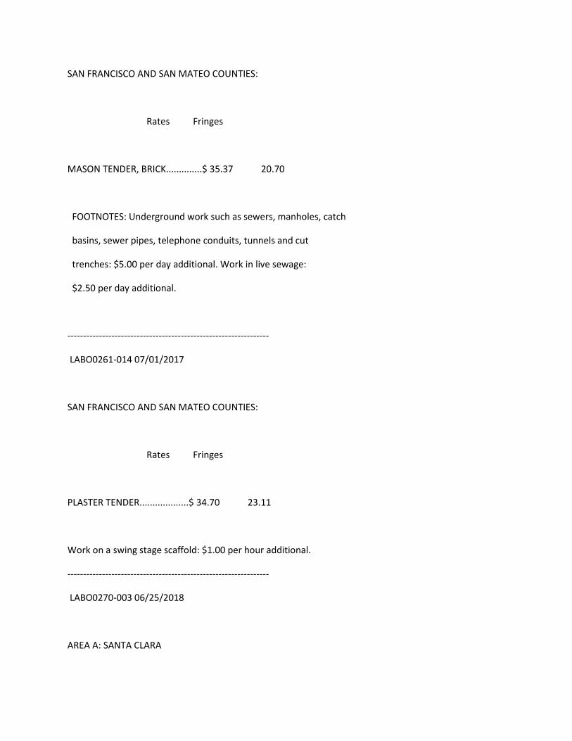
SAN FRANCISCO AND SAN MATEO COUNTIES:
Rates Fringes
MASON TENDER, BRICK..............$ 35.37 20.70
FOOTNOTES: Underground work such as sewers, manholes, catch
basins, sewer pipes, telephone conduits, tunnels and cut
trenches: $5.00 per day additional. Work in live sewage:
$2.50 per day additional.
----------------------------------------------------------------
LABO0261-014 07/01/2017
SAN FRANCISCO AND SAN MATEO COUNTIES:
Rates Fringes
PLASTER TENDER...................$ 34.70 23.11
Work on a swing stage scaffold: $1.00 per hour additional.
----------------------------------------------------------------
LABO0270-003 06/25/2018
AREA A: SANTA CLARA
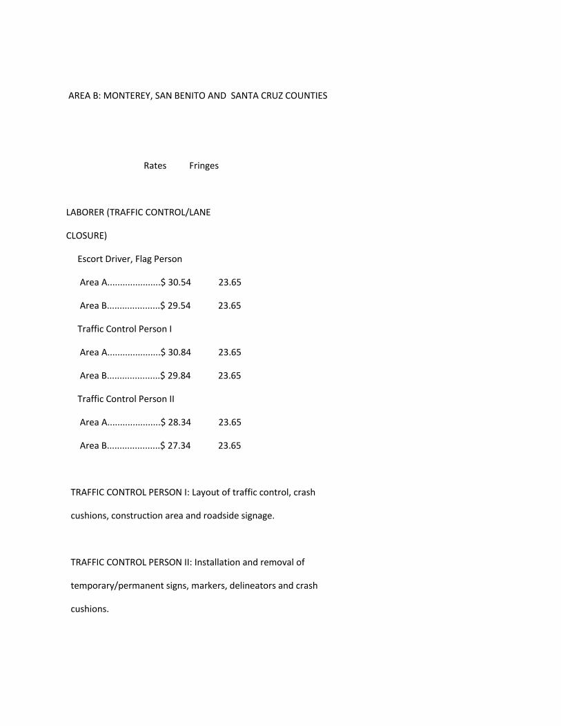
AREA B: MONTEREY, SAN BENITO AND SANTA CRUZ COUNTIES
Rates Fringes
LABORER (TRAFFIC CONTROL/LANE
CLOSURE)
Escort Driver, Flag Person
Area A.....................$ 30.54 23.65
Area B.....................$ 29.54 23.65
Traffic Control Person I
Area A.....................$ 30.84 23.65
Area B.....................$ 29.84 23.65
Traffic Control Person II
Area A.....................$ 28.34 23.65
Area B.....................$ 27.34 23.65
TRAFFIC CONTROL PERSON I: Layout of traffic control, crash
cushions, construction area and roadside signage.
TRAFFIC CONTROL PERSON II: Installation and removal of
temporary/permanent signs, markers, delineators and crash
cushions.
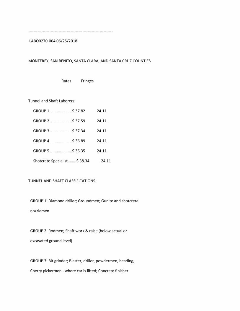
----------------------------------------------------------------
LABO0270-004 06/25/2018
MONTEREY, SAN BENITO, SANTA CLARA, AND SANTA CRUZ COUNTIES
Rates Fringes
Tunnel and Shaft Laborers:
GROUP 1.....................$ 37.82 24.11
GROUP 2.....................$ 37.59 24.11
GROUP 3.....................$ 37.34 24.11
GROUP 4.....................$ 36.89 24.11
GROUP 5.....................$ 36.35 24.11
Shotcrete Specialist........$ 38.34 24.11
TUNNEL AND SHAFT CLASSIFICATIONS
GROUP 1: Diamond driller; Groundmen; Gunite and shotcrete
nozzlemen
GROUP 2: Rodmen; Shaft work & raise (below actual or
excavated ground level)
GROUP 3: Bit grinder; Blaster, driller, powdermen, heading;
Cherry pickermen - where car is lifted; Concrete finisher
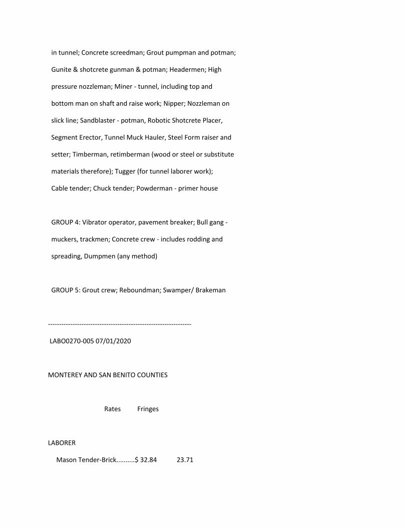
in tunnel; Concrete screedman; Grout pumpman and potman;
Gunite & shotcrete gunman & potman; Headermen; High
pressure nozzleman; Miner - tunnel, including top and
bottom man on shaft and raise work; Nipper; Nozzleman on
slick line; Sandblaster - potman, Robotic Shotcrete Placer,
Segment Erector, Tunnel Muck Hauler, Steel Form raiser and
setter; Timberman, retimberman (wood or steel or substitute
materials therefore); Tugger (for tunnel laborer work);
Cable tender; Chuck tender; Powderman - primer house
GROUP 4: Vibrator operator, pavement breaker; Bull gang -
muckers, trackmen; Concrete crew - includes rodding and
spreading, Dumpmen (any method)
GROUP 5: Grout crew; Reboundman; Swamper/ Brakeman
----------------------------------------------------------------
LABO0270-005 07/01/2020
MONTEREY AND SAN BENITO COUNTIES
Rates Fringes
LABORER
Mason Tender-Brick..........$ 32.84 23.71
----------------------------------------------------------------
LABO0270-007 06/25/2018
MONTEREY, SAN BENITO, AND SANTA CRUZ, COUNTIES
Rates Fringes
LABORER (CONSTRUCTION CRAFT
LABORERS - AREA B)
Construction Specialist
Group.......................$ 30.40 23.20
GROUP 1.....................$ 29.79 23.20
GROUP 1-a...................$ 30.01 23.20
GROUP 1-c...................$ 29.84 23.20
GROUP 1-e...................$ 30.34 23.20
GROUP 1-f...................$ 30.37 23.20
GROUP 2.....................$ 29.64 23.20
GROUP 3.....................$ 29.54 23.20
GROUP 4.....................$ 23.23 23.20
See groups 1-b and 1-d under laborer classifications.
LABORER (GARDENERS,
HORTICULTURAL & LANDSCAPE
LABORERS - AREA B)
(1) New Construction........$ 29.54 23.20
(2) Establishment Warranty
Period......................$ 23.23 23.20
LABORER (GUNITE - AREA B)
GROUP 1.....................$ 29.75 22.31
GROUP 2.....................$ 29.25 22.31
GROUP 3.....................$ 28.66 22.31
GROUP 4.....................$ 28.54 22.31
LABORER (WRECKING - AREA B)
GROUP 1.....................$ 29.79 23.20
GROUP 2.....................$ 29.64 23.20
FOOTNOTES:
Laborers working off or with or from bos'n chairs, swinging
scaffolds, belts shall receive $0.25 per hour above the
applicable wage rate. This shall not apply to workers
entitled to receive the wage rate set forth in Group 1-a
below.
---------------------------------------------------------
LABORER CLASSIFICATIONS
CONSTRUCTION SPECIALIST GROUP: Asphalt ironer and raker;
Chainsaw; Laser beam in connection with laborers' work;
Cast-in- place manhole form setter; Pressure pipelayer;

Davis trencher - 300 or similar type (and all small
trenchers); Blaster; Diamond driller; Multiple unit drill;
Hydraulic drill
GROUP 1: Asphalt spreader boxes (all types); Barko, Wacker
and similar type tampers; Buggymobile; Caulker, bander,
pipewrapper, conduit layer, plastic pipelayer; Certified
hazardous waste worker including Leade Abatement;
Compactors of all types; Concrete and magnesite mixer, 1/2
yd. and under; Concrete pan work; Concrete sander; Concrete
saw; Cribber and/or shoring; Cut granite curb setter;
Dri-pak-it machine; Faller, logloader and bucker; Form
raiser, slip forms; Green cutter; Headerboard, Hubsetter,
aligner, by any method; High pressure blow pipe (1-1/2"" or
over, 100 lbs. pressure/over); Hydro seeder and similar
type; Jackhammer operator; Jacking of pipe over 12 inches;
Jackson and similar type compactor; Kettle tender, pot and
worker applying asphalt, lay-kold, creosote, lime, caustic
and similar type materials (applying means applying,
dipping or handling of such materials); Lagging, sheeting,
whaling, bracing, trenchjacking, lagging hammer; Magnesite,
epoxyresin, fiberglass, mastic worker (wet or dry); No
joint pipe and stripping of same, including repair of
voids; Pavement breaker and spader, including tool grinder;
Perma curb; Pipelayer (including grade checking in
connection with pipelaying); Precast-manhole setter;
Pressure pipe tester; Post hole digger, air, gas and
electric; Power broom sweeper; Power tampers of all types
(except as shown in Group 2); Ram set gun and stud gun;
Riprap stonepaver and rock-slinger, including placing of
sacked concrete and/or sand (wet or dry) and gabions and
similar type; Rotary scarifier or multiple head concrete
chipping scarifier; Roto and Ditch Witch; Rototiller;
Sandblaster, pot, gun, nozzle operators; Signalling and
rigging; Tank cleaner; Tree climber; Turbo blaster;
Vibrascreed, bull float in connection with laborers' work;
Vibrator; Hazardous waste worker (lead removal); Asbestos
and mold removal worker
GROUP 1-a: Joy drill model TWM-2A; Gardner-Denver model DH143
and similar type drills; Track driller; Jack leg driller;
Wagon driller; Mechanical drillers, all types regardless of
type or method of power; Mechanical pipe layers, all types
regardless of type or method of power; Blaster and powder;
All work of loading, placing and blasting of all powder and
explosives of whatever type regardless of method used for
such loading and placing; High scalers (including drilling
of same); Tree topper; Bit grinder
GROUP 1-b: Sewer cleaners shall receive $4.00 per day above

Group 1 wage rates. ""Sewer cleaner"" means any worker who
handles or comes in contact with raw sewage in small
diameter sewers. Those who work inside recently active,
large diameter sewers, and all recently active sewer
manholes shal receive $5.00 per day above Group 1 wage
rates.
GROUP 1-c: Burning and welding in connection with laborers'
work; Synthetic thermoplastics and similar type welding
GROUP 1-d: Maintenance and repair track and road beds. All
employees performing work covered herein shall receive $
.25 per hour above their regular rate for all work
performed on underground structures not specifically
covered herein. This paragraph shall not be construed to
apply to work below ground level in open cut. It shall
apply to cut and cover work of subway construction after
the temporary cover has been placed.
GROUP 1-e: Work on and/or in bell hole footings and shafts
thereof, and work on and in deep footings. (A deep footing
is a hole 15 feet or more in depth.) In the event the
depth of the footing is unknown at the commencement of
excavation, and the final depth exceeds 15 feet, the deep
footing wage rate would apply to all employees for each and

every day worked on or in the excavation of the footing
from the date of inception.
GROUP 1-f: Wire winding machine in connection with guniting
or shot crete
GROUP 2: Asphalt shoveler; Cement dumper and handling dry
cement or gypsum; Choke-setter and rigger (clearing work);
Concrete bucket dumper and chute; Concrete chipping and
grinding; Concrete laborer (wet or dry); Driller tender,
chuck tender, nipper; Guinea chaser (stake), grout crew;
High pressure nozzle, adductor; Hydraulic monitor (over 100
lbs. pressure); Loading and unloading, carrying and hauling
of all rods and materials for use in reinforcing concrete
construction; Pittsburgh chipper and similar type brush
shredders; Sloper; Single foot, hand-held, pneumatic
tamper; All pneumatic, air, gas and electric tools not
listed in Groups 1 through 1-f; Jacking of pipe - under 12
inches
GROUP 3: Construction laborers, including bridge and general
laborer; Dump, load spotter; Flag person; Fire watcher;
Fence erector; Guardrail erector; Gardener, horticultural
and landscape laborer; Jetting; Limber, brush loader and
piler; Pavement marker (button setter); Maintenance, repair
track and road beds; Streetcar and railroad construction
track laborer; Temporary air and water lines, Victaulic or
similar; Tool room attendant (jobsite only)
GROUP 4: Final clean-up work of debris, grounds and building
including but not limited to: street cleaner; cleaning and
washing windows; brick cleaner (jobsite only); material
cleaner (jobsite only). The classification ""material
cleaner"" is to be utilized under the following conditions:
A: at demolition site for the salvage of the material.
B: at the conclusion of a job where the material is to be
salvaged and stocked to be reused on another job.
C: for the cleaning of salvage material at the jobsite or
temporary jobsite yard.
The material cleaner classification should not be used in
the performance of ""form stripping, cleaning and oiling
and moving to the next point of erection"".
--------------------------------------------------------
GUNITE LABORER CLASSIFICATIONS
GROUP 1: Structural Nozzleman
GROUP 2: Nozzleman, Gunman, Potman, Groundman
GROUP 3: Reboundman
GROUP 4: Gunite laborer
----------------------------------------------------------
WRECKING WORK LABORER CLASSIFICATIONS
GROUP 1: Skilled wrecker (removing and salvaging of sash,
windows and materials)
GROUP 2: Semi-skilled wrecker (salvaging of other building
materials)
----------------------------------------------------------------
LABO0270-010 06/25/2018
SANTA CLARA COUNTY
Rates Fringes
LABORER (CONSTRUCTION CRAFT
LABORERS - AREA A:)
Construction Specialist
Group.......................$ 31.49 23.20
GROUP 1.....................$ 30.79 23.20
GROUP 1-a...................$ 31.01 23.20
GROUP 1-c...................$ 30.84 23.20
GROUP 1-e...................$ 31.34 23.20
GROUP 1-f...................$ 30.37 23.20
GROUP 2.....................$ 30.64 23.20
GROUP 3.....................$ 30.54 23.20
GROUP 4.....................$ 24.23 23.20
See groups 1-b and 1-d under laborer classifications.
LABORER (GARDENERS,
HORTICULTURAL & LANDSCAPE
LABORERS - AREA A:)
(1) New Construction........$ 30.54 23.20
(2) Establishment Warranty
Period......................$ 24.23 23.20
LABORER (GUNITE - AREA A:)
GROUP 1.....................$ 30.75 22.31
GROUP 2.....................$ 30.25 22.31
GROUP 3.....................$ 29.66 22.31
GROUP 4.....................$ 29.54 22.31
LABORER (WRECKING - AREA A:)
GROUP 1.....................$ 30.79 23.20
GROUP 2.....................$ 30.64 23.20
FOOTNOTES:
Laborers working off or with or from bos'n chairs, swinging
scaffolds, belts shall receive $0.25 per hour above the
applicable wage rate. This shall not apply to workers
entitled to receive the wage rate set forth in Group 1-a
below.
---------------------------------------------------------
LABORER CLASSIFICATIONS
CONSTRUCTION SPECIALIST GROUP: Asphalt ironer and raker;
Chainsaw; Laser beam in connection with laborers' work;
Cast-in- place manhole form setter; Pressure pipelayer;
Davis trencher - 300 or similar type (and all small
trenchers); Blaster; Diamond driller; Multiple unit drill;
Hydraulic drill
GROUP 1: Asphalt spreader boxes (all types); Barko, Wacker
and similar type tampers; Buggymobile; Caulker, bander,
pipewrapper, conduit layer, plastic pipelayer; Certified
hazardous waste worker including Leade Abatement;
Compactors of all types; Concrete and magnesite mixer, 1/2
yd. and under; Concrete pan work; Concrete sander; Concrete
saw; Cribber and/or shoring; Cut granite curb setter;
Dri-pak-it machine; Faller, logloader and bucker; Form
raiser, slip forms; Green cutter; Headerboard, Hubsetter,
aligner, by any method; High pressure blow pipe (1-1/2"" or
over, 100 lbs. pressure/over); Hydro seeder and similar
type; Jackhammer operator; Jacking of pipe over 12 inches;
Jackson and similar type compactor; Kettle tender, pot and
worker applying asphalt, lay-kold, creosote, lime, caustic
and similar type materials (applying means applying,
dipping or handling of such materials); Lagging, sheeting,
whaling, bracing, trenchjacking, lagging hammer; Magnesite,
epoxyresin, fiberglass, mastic worker (wet or dry); No
joint pipe and stripping of same, including repair of
voids; Pavement breaker and spader, including tool grinder;
Perma curb; Pipelayer (including grade checking in
connection with pipelaying); Precast-manhole setter;
Pressure pipe tester; Post hole digger, air, gas and
electric; Power broom sweeper; Power tampers of all types
(except as shown in Group 2); Ram set gun and stud gun;
Riprap stonepaver and rock-slinger, including placing of
sacked concrete and/or sand (wet or dry) and gabions and
similar type; Rotary scarifier or multiple head concrete
chipping scarifier; Roto and Ditch Witch; Rototiller;
Sandblaster, pot, gun, nozzle operators; Signalling and

rigging; Tank cleaner; Tree climber; Turbo blaster;
Vibrascreed, bull float in connection with laborers' work;
Vibrator; Hazardous waste worker (lead removal); Asbestos
and mold removal worker
GROUP 1-a: Joy drill model TWM-2A; Gardner-Denver model DH143
and similar type drills; Track driller; Jack leg driller;
Wagon driller; Mechanical drillers, all types regardless of
type or method of power; Mechanical pipe layers, all types
regardless of type or method of power; Blaster and powder;
All work of loading, placing and blasting of all powder and
explosives of whatever type regardless of method used for
such loading and placing; High scalers (including drilling
of same); Tree topper; Bit grinder
GROUP 1-b: Sewer cleaners shall receive $4.00 per day above
Group 1 wage rates. ""Sewer cleaner"" means any worker who
handles or comes in contact with raw sewage in small
diameter sewers. Those who work inside recently active,
large diameter sewers, and all recently active sewer
manholes shal receive $5.00 per day above Group 1 wage
rates.
GROUP 1-c: Burning and welding in connection with laborers'
work; Synthetic thermoplastics and similar type welding
GROUP 1-d: Maintenance and repair track and road beds. All
employees performing work covered herein shall receive $
.25 per hour above their regular rate for all work
performed on underground structures not specifically
covered herein. This paragraph shall not be construed to
apply to work below ground level in open cut. It shall
apply to cut and cover work of subway construction after
the temporary cover has been placed.
GROUP 1-e: Work on and/or in bell hole footings and shafts
thereof, and work on and in deep footings. (A deep footing
is a hole 15 feet or more in depth.) In the event the
depth of the footing is unknown at the commencement of
excavation, and the final depth exceeds 15 feet, the deep
footing wage rate would apply to all employees for each and
every day worked on or in the excavation of the footing
from the date of inception.
GROUP 1-f: Wire winding machine in connection with guniting
or shot crete
GROUP 2: Asphalt shoveler; Cement dumper and handling dry
cement or gypsum; Choke-setter and rigger (clearing work);
Concrete bucket dumper and chute; Concrete chipping and
grinding; Concrete laborer (wet or dry); Driller tender,
chuck tender, nipper; Guinea chaser (stake), grout crew;
High pressure nozzle, adductor; Hydraulic monitor (over 100
lbs. pressure); Loading and unloading, carrying and hauling
of all rods and materials for use in reinforcing concrete
construction; Pittsburgh chipper and similar type brush
shredders; Sloper; Single foot, hand-held, pneumatic
tamper; All pneumatic, air, gas and electric tools not
listed in Groups 1 through 1-f; Jacking of pipe - under 12
inches
GROUP 3: Construction laborers, including bridge and general
laborer; Dump, load spotter; Flag person; Fire watcher;
Fence erector; Guardrail erector; Gardener, horticultural
and landscape laborer; Jetting; Limber, brush loader and
piler; Pavement marker (button setter); Maintenance, repair
track and road beds; Streetcar and railroad construction
track laborer; Temporary air and water lines, Victaulic or
similar; Tool room attendant (jobsite only)
GROUP 4: Final clean-up work of debris, grounds and building
including but not limited to: street cleaner; cleaning and
washing windows; brick cleaner (jobsite only); material
cleaner (jobsite only). The classification ""material
cleaner"" is to be utilized under the following conditions:

A: at demolition site for the salvage of the material.
B: at the conclusion of a job where the material is to be
salvaged and stocked to be reused on another job.
C: for the cleaning of salvage material at the jobsite or
temporary jobsite yard.
The material cleaner classification should not be used in
the performance of ""form stripping, cleaning and oiling
and moving to the next point of erection"".
--------------------------------------------------------
GUNITE LABORER CLASSIFICATIONS
GROUP 1: Structural Nozzleman
GROUP 2: Nozzleman, Gunman, Potman, Groundman
GROUP 3: Reboundman
GROUP 4: Gunite laborer
----------------------------------------------------------
WRECKING WORK LABORER CLASSIFICATIONS
GROUP 1: Skilled wrecker (removing and salvaging of sash,
windows and materials)
GROUP 2: Semi-skilled wrecker (salvaging of other building
materials)
----------------------------------------------------------------
LABO0270-011 07/01/2017
MONTEREY, SAN BENITO, SANTA CRUZ, SANTA CLARA COUNTIES
Rates Fringes
LABORER (Plaster Tender).........$ 34.70 21.22
Work on a swing stage scaffold: $1.00 per hour additional.
----------------------------------------------------------------
LABO0294-001 07/01/2020
FRESNO, KINGS AND MADERA COUNTIES
Rates Fringes
LABORER (Brick)
Mason Tender-Brick..........$ 32.84 23.71
----------------------------------------------------------------
LABO0294-002 06/25/2018
FRESNO, KINGS, AND MADERA COUNTIES
Rates Fringes
LABORER (TRAFFIC CONTROL/LANE
CLOSURE)
Escort Driver, Flag Person..$ 29.54 23.65
Traffic Control Person I....$ 29.84 23.65
Traffic Control Person II...$ 27.34 23.65
TRAFFIC CONTROL PERSON I: Layout of traffic control, crash
cushions, construction area and roadside signage.
TRAFFIC CONTROL PERSON II: Installation and removal of
temporary/permanent signs, markers, delineators and crash
cushions.
----------------------------------------------------------------
LABO0294-005 06/25/2018
FRESNO, KINGS, AND MADERA COUNTIES
Rates Fringes
Tunnel and Shaft Laborers:
GROUP 1.....................$ 37.82 24.11
GROUP 2.....................$ 37.59 24.11
GROUP 3.....................$ 37.34 24.11
GROUP 4.....................$ 36.89 24.11
GROUP 5.....................$ 36.35 24.11
Shotcrete Specialist........$ 38.34 24.11
TUNNEL AND SHAFT CLASSIFICATIONS
GROUP 1: Diamond driller; Groundmen; Gunite and shotcrete
nozzlemen
GROUP 2: Rodmen; Shaft work & raise (below actual or
excavated ground level)
GROUP 3: Bit grinder; Blaster, driller, powdermen, heading;
Cherry pickermen - where car is lifted; Concrete finisher
in tunnel; Concrete screedman; Grout pumpman and potman;
Gunite & shotcrete gunman & potman; Headermen; High
pressure nozzleman; Miner - tunnel, including top and
bottom man on shaft and raise work; Nipper; Nozzleman on
slick line; Sandblaster - potman, Robotic Shotcrete Placer,
Segment Erector, Tunnel Muck Hauler, Steel Form raiser and
setter; Timberman, retimberman (wood or steel or substitute
materials therefore); Tugger (for tunnel laborer work);
Cable tender; Chuck tender; Powderman - primer house
GROUP 4: Vibrator operator, pavement breaker; Bull gang -
muckers, trackmen; Concrete crew - includes rodding and
spreading, Dumpmen (any method)
GROUP 5: Grout crew; Reboundman; Swamper/ Brakeman
----------------------------------------------------------------
LABO0294-008 06/25/2018
FRESNO, KINGS, AND MADERA COUNTIES
Rates Fringes
LABORER (CONSTRUCTION CRAFT
LABORERS - AREA B:)
Construction Specialist
Group.......................$ 30.49 23.20
GROUP 1.....................$ 29.79 23.20
GROUP 1-a...................$ 30.01 23.20
GROUP 1-c...................$ 29.84 23.20
GROUP 1-e...................$ 30.34 23.20
GROUP 1-f...................$ 30.37 23.20
GROUP 2.....................$ 29.64 23.20
GROUP 3.....................$ 29.54 23.20
GROUP 4.....................$ 23.23 23.20
See groups 1-b and 1-d under laborer classifications.
LABORER (GARDENERS,
HORTICULTURAL & LANDSCAPE
LABORERS - AREA B:)
(1) New Construction........$ 29.54 23.20
(2) Establishment Warranty
Period......................$ 23.23 23.20
LABORER (GUNITE - AREA B:)
GROUP 1.....................$ 29.75 22.31
GROUP 2.....................$ 29.25 22.31
GROUP 3.....................$ 28.66 22.31
GROUP 4.....................$ 28.54 22.31
LABORER (WRECKING - AREA B:)
GROUP 1.....................$ 29.79 23.20
GROUP 2.....................$ 29.64 23.20
FOOTNOTES:
Laborers working off or with or from bos'n chairs, swinging
scaffolds, belts shall receive $0.25 per hour above the
applicable wage rate. This shall not apply to workers
entitled to receive the wage rate set forth in Group 1-a
below.
---------------------------------------------------------
LABORER CLASSIFICATIONS
CONSTRUCTION SPECIALIST GROUP: Asphalt ironer and raker;
Chainsaw; Laser beam in connection with laborers' work;
Cast-in- place manhole form setter; Pressure pipelayer;
Davis trencher - 300 or similar type (and all small
trenchers); Blaster; Diamond driller; Multiple unit drill;
Hydraulic drill
GROUP 1: Asphalt spreader boxes (all types); Barko, Wacker
and similar type tampers; Buggymobile; Caulker, bander,
pipewrapper, conduit layer, plastic pipelayer; Certified
hazardous waste worker including Leade Abatement;
Compactors of all types; Concrete and magnesite mixer, 1/2
yd. and under; Concrete pan work; Concrete sander; Concrete
saw; Cribber and/or shoring; Cut granite curb setter;
Dri-pak-it machine; Faller, logloader and bucker; Form
raiser, slip forms; Green cutter; Headerboard, Hubsetter,

aligner, by any method; High pressure blow pipe (1-1/2"" or
over, 100 lbs. pressure/over); Hydro seeder and similar
type; Jackhammer operator; Jacking of pipe over 12 inches;
Jackson and similar type compactor; Kettle tender, pot and
worker applying asphalt, lay-kold, creosote, lime, caustic
and similar type materials (applying means applying,
dipping or handling of such materials); Lagging, sheeting,
whaling, bracing, trenchjacking, lagging hammer; Magnesite,
epoxyresin, fiberglass, mastic worker (wet or dry); No
joint pipe and stripping of same, including repair of
voids; Pavement breaker and spader, including tool grinder;
Perma curb; Pipelayer (including grade checking in
connection with pipelaying); Precast-manhole setter;
Pressure pipe tester; Post hole digger, air, gas and
electric; Power broom sweeper; Power tampers of all types
(except as shown in Group 2); Ram set gun and stud gun;
Riprap stonepaver and rock-slinger, including placing of
sacked concrete and/or sand (wet or dry) and gabions and
similar type; Rotary scarifier or multiple head concrete
chipping scarifier; Roto and Ditch Witch; Rototiller;
Sandblaster, pot, gun, nozzle operators; Signalling and
rigging; Tank cleaner; Tree climber; Turbo blaster;
Vibrascreed, bull float in connection with laborers' work;
Vibrator; Hazardous waste worker (lead removal); Asbestos
and mold removal worker

GROUP 1-a: Joy drill model TWM-2A; Gardner-Denver model DH143
and similar type drills; Track driller; Jack leg driller;
Wagon driller; Mechanical drillers, all types regardless of
type or method of power; Mechanical pipe layers, all types
regardless of type or method of power; Blaster and powder;
All work of loading, placing and blasting of all powder and
explosives of whatever type regardless of method used for
such loading and placing; High scalers (including drilling
of same); Tree topper; Bit grinder
GROUP 1-b: Sewer cleaners shall receive $4.00 per day above
Group 1 wage rates. ""Sewer cleaner"" means any worker who
handles or comes in contact with raw sewage in small
diameter sewers. Those who work inside recently active,
large diameter sewers, and all recently active sewer
manholes shal receive $5.00 per day above Group 1 wage
rates.
GROUP 1-c: Burning and welding in connection with laborers'
work; Synthetic thermoplastics and similar type welding
GROUP 1-d: Maintenance and repair track and road beds. All
employees performing work covered herein shall receive $
.25 per hour above their regular rate for all work
performed on underground structures not specifically
covered herein. This paragraph shall not be construed to
apply to work below ground level in open cut. It shall
apply to cut and cover work of subway construction after
the temporary cover has been placed.
GROUP 1-e: Work on and/or in bell hole footings and shafts
thereof, and work on and in deep footings. (A deep footing
is a hole 15 feet or more in depth.) In the event the
depth of the footing is unknown at the commencement of
excavation, and the final depth exceeds 15 feet, the deep
footing wage rate would apply to all employees for each and
every day worked on or in the excavation of the footing
from the date of inception.
GROUP 1-f: Wire winding machine in connection with guniting
or shot crete
GROUP 2: Asphalt shoveler; Cement dumper and handling dry
cement or gypsum; Choke-setter and rigger (clearing work);
Concrete bucket dumper and chute; Concrete chipping and
grinding; Concrete laborer (wet or dry); Driller tender,
chuck tender, nipper; Guinea chaser (stake), grout crew;
High pressure nozzle, adductor; Hydraulic monitor (over 100
lbs. pressure); Loading and unloading, carrying and hauling

of all rods and materials for use in reinforcing concrete
construction; Pittsburgh chipper and similar type brush
shredders; Sloper; Single foot, hand-held, pneumatic
tamper; All pneumatic, air, gas and electric tools not
listed in Groups 1 through 1-f; Jacking of pipe - under 12
inches
GROUP 3: Construction laborers, including bridge and general
laborer; Dump, load spotter; Flag person; Fire watcher;
Fence erector; Guardrail erector; Gardener, horticultural
and landscape laborer; Jetting; Limber, brush loader and
piler; Pavement marker (button setter); Maintenance, repair
track and road beds; Streetcar and railroad construction
track laborer; Temporary air and water lines, Victaulic or
similar; Tool room attendant (jobsite only)
GROUP 4: Final clean-up work of debris, grounds and building
including but not limited to: street cleaner; cleaning and
washing windows; brick cleaner (jobsite only); material
cleaner (jobsite only). The classification ""material
cleaner"" is to be utilized under the following conditions:
A: at demolition site for the salvage of the material.
B: at the conclusion of a job where the material is to be
salvaged and stocked to be reused on another job.
C: for the cleaning of salvage material at the jobsite or

temporary jobsite yard.
The material cleaner classification should not be used in
the performance of ""form stripping, cleaning and oiling
and moving to the next point of erection"".
--------------------------------------------------------
GUNITE LABORER CLASSIFICATIONS
GROUP 1: Structural Nozzleman
GROUP 2: Nozzleman, Gunman, Potman, Groundman
GROUP 3: Reboundman
GROUP 4: Gunite laborer
----------------------------------------------------------
WRECKING WORK LABORER CLASSIFICATIONS
GROUP 1: Skilled wrecker (removing and salvaging of sash,
windows and materials)
GROUP 2: Semi-skilled wrecker (salvaging of other building
materials)
----------------------------------------------------------------
LABO0294-010 07/01/2018
CALAVERAS, FRESNO, KINGS, MADERA, MARIPOSA, MERCED, SAN
JOAQUIN, STANISLAUS & TUOLUMNE
Rates Fringes
Plasterer tender.................$ 32.02 23.00
Work on a swing stage scaffold: $1.00 per hour additional.
----------------------------------------------------------------
LABO0294-011 07/01/2017
FRESNO, KINGS, AND MADERA COUNTIES
Rates Fringes
LABORER (Plaster Tender).........$ 31.02 22.52
Work on a swing stage scaffold: $1.00 per hour additional.
----------------------------------------------------------------
LABO0304-002 06/25/2018
ALAMEDA COUNTY
Rates Fringes
LABORER (TRAFFIC CONTROL/LANE
CLOSURE)
Escort Driver, Flag Person..$ 30.54 23.65
Traffic Control Person I....$ 30.84 23.65
Traffic Control Person II...$ 28.34 23.65
TRAFFIC CONTROL PERSON I: Layout of traffic control, crash
cushions, construction area and roadside signage.
TRAFFIC CONTROL PERSON II: Installation and removal of
temporary/permanent signs, markers, delineators and crash
cushions.
----------------------------------------------------------------
LABO0304-003 06/26/2017
ALAMEDA COUNTY
Rates Fringes
Tunnel and Shaft Laborers:
GROUP 1.....................$ 36.60 24.83
GROUP 2.....................$ 36.37 24.83
GROUP 3.....................$ 36.12 24.83
GROUP 4.....................$ 35.67 24.83
GROUP 5.....................$ 35.13 24.83
Shotcrete Specialist........$ 37.12 24.83
TUNNEL AND SHAFT CLASSIFICATIONS
GROUP 1: Diamond driller; Groundmen; Gunite and shotcrete
nozzlemen
GROUP 2: Rodmen; Shaft work & raise (below actual or
excavated ground level)
GROUP 3: Bit grinder; Blaster, driller, powdermen, heading;
Cherry pickermen - where car is lifted; Concrete finisher
in tunnel; Concrete screedman; Grout pumpman and potman;
Gunite & shotcrete gunman & potman; Headermen; High
pressure nozzleman; Miner - tunnel, including top and
bottom man on shaft and raise work; Nipper; Nozzleman on
slick line; Sandblaster - potman, Robotic Shotcrete Placer,
Segment Erector, Tunnel Muck Hauler, Steel Form raiser and
setter; Timberman, retimberman (wood or steel or substitute
materials therefore); Tugger (for tunnel laborer work);
Cable tender; Chuck tender; Powderman - primer house
GROUP 4: Vibrator operator, pavement breaker; Bull gang -
muckers, trackmen; Concrete crew - includes rodding and
spreading, Dumpmen (any method)
GROUP 5: Grout crew; Reboundman; Swamper/ Brakeman
----------------------------------------------------------------
LABO0304-004 06/25/2018
ALAMEDA COUNTY
Rates Fringes
LABORER (CONSTRUCTION CRAFT
LABORERS - AREA A:)
Construction Specialist
Group.......................$ 31.49 23.20
GROUP 1.....................$ 30.79 23.20
GROUP 1-a...................$ 31.01 23.20
GROUP 1-c...................$ 30.84 23.20
GROUP 1-e...................$ 31.34 23.20
GROUP 1-f...................$ 30.37 23.20
GROUP 2.....................$ 30.64 23.20
GROUP 3.....................$ 30.54 23.20
GROUP 4.....................$ 24.23 23.20
See groups 1-b and 1-d under laborer classifications.
LABORER (GARDENERS,
HORTICULTURAL & LANDSCAPE
LABORERS - AREA A:)
(1) New Construction........$ 30.54 23.20
(2) Establishment Warranty
Period......................$ 24.23 23.20
LABORER (GUNITE - AREA A:)
GROUP 1.....................$ 30.75 22.31
GROUP 2.....................$ 30.25 22.31
GROUP 3.....................$ 29.66 22.31
GROUP 4.....................$ 29.54 22.31
LABORER (WRECKING - AREA A:)
GROUP 1.....................$ 30.79 23.20
GROUP 2.....................$ 30.64 23.20
FOOTNOTES:
Laborers working off or with or from bos'n chairs, swinging
scaffolds, belts shall receive $0.25 per hour above the
applicable wage rate. This shall not apply to workers
entitled to receive the wage rate set forth in Group 1-a
below.
---------------------------------------------------------
LABORER CLASSIFICATIONS
CONSTRUCTION SPECIALIST GROUP: Asphalt ironer and raker;
Chainsaw; Laser beam in connection with laborers' work;
Cast-in- place manhole form setter; Pressure pipelayer;
Davis trencher - 300 or similar type (and all small
trenchers); Blaster; Diamond driller; Multiple unit drill;
Hydraulic drill
GROUP 1: Asphalt spreader boxes (all types); Barko, Wacker
and similar type tampers; Buggymobile; Caulker, bander,
pipewrapper, conduit layer, plastic pipelayer; Certified
hazardous waste worker including Leade Abatement;
Compactors of all types; Concrete and magnesite mixer, 1/2
yd. and under; Concrete pan work; Concrete sander; Concrete
saw; Cribber and/or shoring; Cut granite curb setter;
Dri-pak-it machine; Faller, logloader and bucker; Form
raiser, slip forms; Green cutter; Headerboard, Hubsetter,
aligner, by any method; High pressure blow pipe (1-1/2"" or

over, 100 lbs. pressure/over); Hydro seeder and similar
type; Jackhammer operator; Jacking of pipe over 12 inches;
Jackson and similar type compactor; Kettle tender, pot and
worker applying asphalt, lay-kold, creosote, lime, caustic
and similar type materials (applying means applying,
dipping or handling of such materials); Lagging, sheeting,
whaling, bracing, trenchjacking, lagging hammer; Magnesite,
epoxyresin, fiberglass, mastic worker (wet or dry); No
joint pipe and stripping of same, including repair of
voids; Pavement breaker and spader, including tool grinder;
Perma curb; Pipelayer (including grade checking in
connection with pipelaying); Precast-manhole setter;
Pressure pipe tester; Post hole digger, air, gas and
electric; Power broom sweeper; Power tampers of all types
(except as shown in Group 2); Ram set gun and stud gun;
Riprap stonepaver and rock-slinger, including placing of
sacked concrete and/or sand (wet or dry) and gabions and
similar type; Rotary scarifier or multiple head concrete
chipping scarifier; Roto and Ditch Witch; Rototiller;
Sandblaster, pot, gun, nozzle operators; Signalling and
rigging; Tank cleaner; Tree climber; Turbo blaster;
Vibrascreed, bull float in connection with laborers' work;
Vibrator; Hazardous waste worker (lead removal); Asbestos
and mold removal worker

GROUP 1-a: Joy drill model TWM-2A; Gardner-Denver model DH143
and similar type drills; Track driller; Jack leg driller;
Wagon driller; Mechanical drillers, all types regardless of
type or method of power; Mechanical pipe layers, all types
regardless of type or method of power; Blaster and powder;
All work of loading, placing and blasting of all powder and
explosives of whatever type regardless of method used for
such loading and placing; High scalers (including drilling
of same); Tree topper; Bit grinder
GROUP 1-b: Sewer cleaners shall receive $4.00 per day above
Group 1 wage rates. ""Sewer cleaner"" means any worker who
handles or comes in contact with raw sewage in small
diameter sewers. Those who work inside recently active,
large diameter sewers, and all recently active sewer
manholes shal receive $5.00 per day above Group 1 wage
rates.
GROUP 1-c: Burning and welding in connection with laborers'
work; Synthetic thermoplastics and similar type welding
GROUP 1-d: Maintenance and repair track and road beds. All
employees performing work covered herein shall receive $
.25 per hour above their regular rate for all work
performed on underground structures not specifically
covered herein. This paragraph shall not be construed to
apply to work below ground level in open cut. It shall
apply to cut and cover work of subway construction after
the temporary cover has been placed.
GROUP 1-e: Work on and/or in bell hole footings and shafts
thereof, and work on and in deep footings. (A deep footing
is a hole 15 feet or more in depth.) In the event the
depth of the footing is unknown at the commencement of
excavation, and the final depth exceeds 15 feet, the deep
footing wage rate would apply to all employees for each and
every day worked on or in the excavation of the footing
from the date of inception.
GROUP 1-f: Wire winding machine in connection with guniting
or shot crete
GROUP 2: Asphalt shoveler; Cement dumper and handling dry
cement or gypsum; Choke-setter and rigger (clearing work);
Concrete bucket dumper and chute; Concrete chipping and
grinding; Concrete laborer (wet or dry); Driller tender,
chuck tender, nipper; Guinea chaser (stake), grout crew;
High pressure nozzle, adductor; Hydraulic monitor (over 100
lbs. pressure); Loading and unloading, carrying and hauling
of all rods and materials for use in reinforcing concrete

construction; Pittsburgh chipper and similar type brush
shredders; Sloper; Single foot, hand-held, pneumatic
tamper; All pneumatic, air, gas and electric tools not
listed in Groups 1 through 1-f; Jacking of pipe - under 12
inches
GROUP 3: Construction laborers, including bridge and general
laborer; Dump, load spotter; Flag person; Fire watcher;
Fence erector; Guardrail erector; Gardener, horticultural
and landscape laborer; Jetting; Limber, brush loader and
piler; Pavement marker (button setter); Maintenance, repair
track and road beds; Streetcar and railroad construction
track laborer; Temporary air and water lines, Victaulic or
similar; Tool room attendant (jobsite only)
GROUP 4: Final clean-up work of debris, grounds and building
including but not limited to: street cleaner; cleaning and
washing windows; brick cleaner (jobsite only); material
cleaner (jobsite only). The classification ""material
cleaner"" is to be utilized under the following conditions:
A: at demolition site for the salvage of the material.
B: at the conclusion of a job where the material is to be
salvaged and stocked to be reused on another job.
C: for the cleaning of salvage material at the jobsite or
temporary jobsite yard.

The material cleaner classification should not be used in
the performance of ""form stripping, cleaning and oiling
and moving to the next point of erection"".
--------------------------------------------------------
GUNITE LABORER CLASSIFICATIONS
GROUP 1: Structural Nozzleman
GROUP 2: Nozzleman, Gunman, Potman, Groundman
GROUP 3: Reboundman
GROUP 4: Gunite laborer
----------------------------------------------------------
WRECKING WORK LABORER CLASSIFICATIONS
GROUP 1: Skilled wrecker (removing and salvaging of sash,
windows and materials)
GROUP 2: Semi-skilled wrecker (salvaging of other building
materials)
----------------------------------------------------------------
LABO0304-005 05/01/2018
ALAMEDA COUNTY
Rates Fringes
Brick Tender.....................$ 35.37 20.70
FOOTNOTES: Work on jobs where heat-protective clothing is
required: $2.00 per hour additional. Work at grinders: $.25
per hour additional. Manhole work: $2.00 per day additional.
----------------------------------------------------------------
LABO0304-008 07/01/2017
ALAMEDA AND CONTRA COSTA COUNTIES:
Rates Fringes
Plasterer tender.................$ 34.70 23.11
Work on a swing stage scaffold: $1.00 per hour additional.

----------------------------------------------------------------
LABO0324-002 06/25/2018
CONTRA COSTA COUNTY
Rates Fringes
LABORER (TRAFFIC CONTROL/LANE
CLOSURE)
Escort Driver, Flag Person..$ 30.54 23.65
Traffic Control Person I....$ 30.84 23.65
Traffic Control Person II...$ 28.34 23.65
TRAFFIC CONTROL PERSON I: Layout of traffic control, crash
cushions, construction area and roadside signage.
TRAFFIC CONTROL PERSON II: Installation and removal of
temporary/permanent signs, markers, delineators and crash
cushions.
----------------------------------------------------------------
LABO0324-006 06/25/2018
CONTRA COSTA COUNTY
Rates Fringes
Tunnel and Shaft Laborers:
GROUP 1.....................$ 37.82 24.11
GROUP 2.....................$ 37.59 24.11
GROUP 3.....................$ 37.34 24.11
GROUP 4.....................$ 36.89 24.11
GROUP 5.....................$ 36.35 24.11
Shotcrete Specialist........$ 38.34 24.11
TUNNEL AND SHAFT CLASSIFICATIONS
GROUP 1: Diamond driller; Groundmen; Gunite and shotcrete
nozzlemen
GROUP 2: Rodmen; Shaft work & raise (below actual or
excavated ground level)
GROUP 3: Bit grinder; Blaster, driller, powdermen, heading;
Cherry pickermen - where car is lifted; Concrete finisher
in tunnel; Concrete screedman; Grout pumpman and potman;
Gunite & shotcrete gunman & potman; Headermen; High
pressure nozzleman; Miner - tunnel, including top and
bottom man on shaft and raise work; Nipper; Nozzleman on
slick line; Sandblaster - potman, Robotic Shotcrete Placer,
Segment Erector, Tunnel Muck Hauler, Steel Form raiser and
setter; Timberman, retimberman (wood or steel or substitute
materials therefore); Tugger (for tunnel laborer work);
Cable tender; Chuck tender; Powderman - primer house
GROUP 4: Vibrator operator, pavement breaker; Bull gang -
muckers, trackmen; Concrete crew - includes rodding and
spreading, Dumpmen (any method)
GROUP 5: Grout crew; Reboundman; Swamper/ Brakeman
----------------------------------------------------------------
LABO0324-012 06/25/2018
CONTRA COSTA COUNTY
Rates Fringes
LABORER (CONSTRUCTION CRAFT
LABORERS - AREA A:)
Construction Specialist
Group.......................$ 31.49 23.20
GROUP 1.....................$ 30.79 23.20
GROUP 1-a...................$ 31.01 23.20
GROUP 1-c...................$ 30.84 23.20
GROUP 1-e...................$ 31.34 23.20
GROUP 1-f...................$ 30.37 23.20
GROUP 1-g...................$ 30.99 23.20
GROUP 2.....................$ 30.64 23.20
GROUP 3.....................$ 30.54 23.20
GROUP 4.....................$ 24.23 23.20
See groups 1-b and 1-d under laborer classifications.
LABORER (GARDENERS,
HORTICULURAL & LANDSCAPE
LABORERS - AREA A:)
(1) New Construction........$ 30.54 23.20
(2) Establishment Warranty
Period......................$ 24.23 23.20
LABORER (GUNITE - AREA A:)
GROUP 1.....................$ 30.75 22.31
GROUP 2.....................$ 30.25 22.31
GROUP 3.....................$ 29.66 22.31
GROUP 4.....................$ 29.54 22.31
LABORER (WRECKING - AREA A:)
GROUP 1.....................$ 30.79 23.20
GROUP 2.....................$ 30.64 23.20
FOOTNOTES:
Laborers working off or with or from bos'n chairs, swinging
scaffolds, belts shall receive $0.25 per hour above the

applicable wage rate. This shall not apply to workers
entitled to receive the wage rate set forth in Group 1-a
below.
---------------------------------------------------------
LABORER CLASSIFICATIONS
CONSTRUCTION SPECIALIST GROUP: Asphalt ironer and raker;
Chainsaw; Laser beam in connection with laborers' work;
Cast-in- place manhole form setter; Pressure pipelayer;
Davis trencher - 300 or similar type (and all small
trenchers); Blaster; Diamond driller; Multiple unit drill;
Hydraulic drill
GROUP 1: Asphalt spreader boxes (all types); Barko, Wacker
and similar type tampers; Buggymobile; Caulker, bander,
pipewrapper, conduit layer, plastic pipelayer; Certified
hazardous waste worker including Leade Abatement;
Compactors of all types; Concrete and magnesite mixer, 1/2
yd. and under; Concrete pan work; Concrete sander; Concrete
saw; Cribber and/or shoring; Cut granite curb setter;
Dri-pak-it machine; Faller, logloader and bucker; Form
raiser, slip forms; Green cutter; Headerboard, Hubsetter,

aligner, by any method; High pressure blow pipe (1-1/2"" or
over, 100 lbs. pressure/over); Hydro seeder and similar
type; Jackhammer operator; Jacking of pipe over 12 inches;
Jackson and similar type compactor; Kettle tender, pot and
worker applying asphalt, lay-kold, creosote, lime, caustic
and similar type materials (applying means applying,
dipping or handling of such materials); Lagging, sheeting,
whaling, bracing, trenchjacking, lagging hammer; Magnesite,
epoxyresin, fiberglass, mastic worker (wet or dry); No
joint pipe and stripping of same, including repair of
voids; Pavement breaker and spader, including tool grinder;
Perma curb; Pipelayer (including grade checking in
connection with pipelaying); Precast-manhole setter;
Pressure pipe tester; Post hole digger, air, gas and
electric; Power broom sweeper; Power tampers of all types
(except as shown in Group 2); Ram set gun and stud gun;
Riprap stonepaver and rock-slinger, including placing of
sacked concrete and/or sand (wet or dry) and gabions and
similar type; Rotary scarifier or multiple head concrete
chipping scarifier; Roto and Ditch Witch; Rototiller;
Sandblaster, pot, gun, nozzle operators; Signalling and
rigging; Tank cleaner; Tree climber; Turbo blaster;
Vibrascreed, bull float in connection with laborers' work;
Vibrator; Hazardous waste worker (lead removal); Asbestos
and mold removal worker

GROUP 1-a: Joy drill model TWM-2A; Gardner-Denver model DH143
and similar type drills; Track driller; Jack leg driller;
Wagon driller; Mechanical drillers, all types regardless of
type or method of power; Mechanical pipe layers, all types
regardless of type or method of power; Blaster and powder;
All work of loading, placing and blasting of all powder and
explosives of whatever type regardless of method used for
such loading and placing; High scalers (including drilling
of same); Tree topper; Bit grinder
GROUP 1-b: Sewer cleaners shall receive $4.00 per day above
Group 1 wage rates. ""Sewer cleaner"" means any worker who
handles or comes in contact with raw sewage in small
diameter sewers. Those who work inside recently active,
large diameter sewers, and all recently active sewer
manholes shal receive $5.00 per day above Group 1 wage
rates.
GROUP 1-c: Burning and welding in connection with laborers'
work; Synthetic thermoplastics and similar type welding
GROUP 1-d: Maintenance and repair track and road beds. All
employees performing work covered herein shall receive $
.25 per hour above their regular rate for all work
performed on underground structures not specifically
covered herein. This paragraph shall not be construed to
apply to work below ground level in open cut. It shall
apply to cut and cover work of subway construction after
the temporary cover has been placed.
GROUP 1-e: Work on and/or in bell hole footings and shafts
thereof, and work on and in deep footings. (A deep footing
is a hole 15 feet or more in depth.) In the event the
depth of the footing is unknown at the commencement of
excavation, and the final depth exceeds 15 feet, the deep
footing wage rate would apply to all employees for each and
every day worked on or in the excavation of the footing
from the date of inception.
GROUP 1-f: Wire winding machine in connection with guniting
or shot crete
GROUP 1-g, CONTRA COSTA COUNTY: Pipelayer (including grade
checking in connection with pipelaying); Caulker; Bander;
Pipewrapper; Conduit layer; Plastic pipe layer; Pressure
pipe tester; No joint pipe and stripping of same, including
repair of voids; Precast manhole setters, cast in place
manhole form setters

GROUP 2: Asphalt shoveler; Cement dumper and handling dry
cement or gypsum; Choke-setter and rigger (clearing work);
Concrete bucket dumper and chute; Concrete chipping and
grinding; Concrete laborer (wet or dry); Driller tender,
chuck tender, nipper; Guinea chaser (stake), grout crew;
High pressure nozzle, adductor; Hydraulic monitor (over 100
lbs. pressure); Loading and unloading, carrying and hauling
of all rods and materials for use in reinforcing concrete
construction; Pittsburgh chipper and similar type brush
shredders; Sloper; Single foot, hand-held, pneumatic
tamper; All pneumatic, air, gas and electric tools not
listed in Groups 1 through 1-f; Jacking of pipe - under 12
inches
GROUP 3: Construction laborers, including bridge and general
laborer; Dump, load spotter; Flag person; Fire watcher;
Fence erector; Guardrail erector; Gardener, horticultural
and landscape laborer; Jetting; Limber, brush loader and
piler; Pavement marker (button setter); Maintenance, repair
track and road beds; Streetcar and railroad construction
track laborer; Temporary air and water lines, Victaulic or
similar; Tool room attendant (jobsite only)
GROUP 4: Final clean-up work of debris, grounds and building
including but not limited to: street cleaner; cleaning and

washing windows; brick cleaner (jobsite only); material
cleaner (jobsite only). The classification ""material
cleaner"" is to be utilized under the following conditions:
A: at demolition site for the salvage of the material.
B: at the conclusion of a job where the material is to be
salvaged and stocked to be reused on another job.
C: for the cleaning of salvage material at the jobsite or
temporary jobsite yard.
The material cleaner classification should not be used in
the performance of ""form stripping, cleaning and oiling
and moving to the next point of erection"".
--------------------------------------------------------
GUNITE LABORER CLASSIFICATIONS
GROUP 1: Structural Nozzleman
GROUP 2: Nozzleman, Gunman, Potman, Groundman
GROUP 3: Reboundman
GROUP 4: Gunite laborer
----------------------------------------------------------
WRECKING WORK LABORER CLASSIFICATIONS
GROUP 1: Skilled wrecker (removing and salvaging of sash,
windows and materials)
GROUP 2: Semi-skilled wrecker (salvaging of other building
materials)
GROUP 1-g, CONTRA COSTA COUNTY: Pipelayer (including grade
checking in connection with pipelaying); Caulker; Bander;
Pipewrapper; Conduit layer; Plastic pipe layer; Pressure
pipe tester; No joint pipe and stripping of same, including
repair of voids; Precast manhole setters, cast in place
manhole form setters
----------------------------------------------------------------
LABO0324-014 05/01/2018
CONTRA COSTA COUNTY:
Rates Fringes
Brick Tender.....................$ 35.37 20.70
FOOTNOTES: Work on jobs where heat-protective clothing is
required: $2.00 per hour additional. Work at grinders: $.25
per hour additional. Manhole work: $2.00 per day additional.
----------------------------------------------------------------
LABO0324-018 07/01/2018
ALAMEDA AND CONTRA COSTA COUNTIES:
Rates Fringes
Plasterer tender.................$ 37.14 22.32
Work on a swing stage scaffold: $1.00 per hour additional.
----------------------------------------------------------------
LABO1130-002 06/25/2018
MARIPOSA, MERCED, STANISLAUS, AND TUOLUMNE COUNTIES
Rates Fringes
LABORER (TRAFFIC CONTROL/LANE
CLOSURE)
Escort Driver, Flag Person..$ 29.54 23.65
Traffic Control Person I....$ 29.84 23.65
Traffic Control Person II...$ 27.34 23.65
TRAFFIC CONTROL PERSON I: Layout of traffic control, crash
cushions, construction area and roadside signage.
TRAFFIC CONTROL PERSON II: Installation and removal of
temporary/permanent signs, markers, delineators and crash
cushions.
----------------------------------------------------------------
LABO1130-003 06/26/2017
MARIPOSA, MERCED, STANISLAUS, AND TUOLUMNE COUNTIES
Rates Fringes
Tunnel and Shaft Laborers:
GROUP 1.....................$ 36.60 24.83
GROUP 2.....................$ 36.37 24.83
GROUP 3.....................$ 36.12 24.83
GROUP 4.....................$ 35.67 24.83
GROUP 5.....................$ 35.13 24.83
Shotcrete Specialist........$ 37.12 24.83
TUNNEL AND SHAFT CLASSIFICATIONS
GROUP 1: Diamond driller; Groundmen; Gunite and shotcrete
nozzlemen
GROUP 2: Rodmen; Shaft work & raise (below actual or
excavated ground level)
GROUP 3: Bit grinder; Blaster, driller, powdermen, heading;
Cherry pickermen - where car is lifted; Concrete finisher
in tunnel; Concrete screedman; Grout pumpman and potman;
Gunite & shotcrete gunman & potman; Headermen; High
pressure nozzleman; Miner - tunnel, including top and
bottom man on shaft and raise work; Nipper; Nozzleman on
slick line; Sandblaster - potman, Robotic Shotcrete Placer,
Segment Erector, Tunnel Muck Hauler, Steel Form raiser and
setter; Timberman, retimberman (wood or steel or substitute
materials therefore); Tugger (for tunnel laborer work);
Cable tender; Chuck tender; Powderman - primer house
GROUP 4: Vibrator operator, pavement breaker; Bull gang -
muckers, trackmen; Concrete crew - includes rodding and
spreading, Dumpmen (any method)
GROUP 5: Grout crew; Reboundman; Swamper/ Brakeman
----------------------------------------------------------------
LABO1130-005 07/01/2018
MARIPOSA, MERCED, STANISLAUS AND TUOLUMNE COUNTIES
Rates Fringes
LABORER
Mason Tender-Brick..........$ 31.20 22.20
----------------------------------------------------------------
LABO1130-007 06/25/2018
MARIPOSA, MERCED, STANISLAUS, AND TUOLUMNE , COUNTIES
Rates Fringes
LABORER (CONSTRUCTION CRAFT
LABORERS - AREA B:)
Construction Specialist
Group.......................$ 30.49 23.20
GROUP 1.....................$ 29.79 23.20
GROUP 1-a...................$ 30.01 23.20
GROUP 1-c...................$ 29.84 23.20

GROUP 1-e...................$ 30.34 23.20
GROUP 1-f...................$ 29.37 23.20
GROUP 2.....................$ 29.64 23.20
GROUP 3.....................$ 29.54 23.20
GROUP 4.....................$ 23.23 23.20
See groups 1-b and 1-d under laborer classifications.
LABORER (GARDENERS,
HORTICULTURAL & LANDSCAPE
LABORERS - AREA B:)
(1) New Construction........$ 29.54 23.20
(2) Establishment Warranty
Period......................$ 23.23 23.20
LABORER (GUNITE - AREA B:)
GROUP 1.....................$ 29.75 22.31
GROUP 2.....................$ 29.25 22.31
GROUP 3.....................$ 28.66 22.31
GROUP 4.....................$ 28.54 22.31
LABORER (WRECKING - AREA B:)
GROUP 1.....................$ 29.79 23.20
GROUP 2.....................$ 29.64 23.20
FOOTNOTES:
Laborers working off or with or from bos'n chairs, swinging
scaffolds, belts shall receive $0.25 per hour above the
applicable wage rate. This shall not apply to workers

entitled to receive the wage rate set forth in Group 1-a
below.
---------------------------------------------------------
LABORER CLASSIFICATIONS
CONSTRUCTION SPECIALIST GROUP: Asphalt ironer and raker;
Chainsaw; Laser beam in connection with laborers' work;
Cast-in- place manhole form setter; Pressure pipelayer;
Davis trencher - 300 or similar type (and all small
trenchers); Blaster; Diamond driller; Multiple unit drill;
Hydraulic drill
GROUP 1: Asphalt spreader boxes (all types); Barko, Wacker
and similar type tampers; Buggymobile; Caulker, bander,
pipewrapper, conduit layer, plastic pipelayer; Certified
hazardous waste worker including Leade Abatement;
Compactors of all types; Concrete and magnesite mixer, 1/2
yd. and under; Concrete pan work; Concrete sander; Concrete
saw; Cribber and/or shoring; Cut granite curb setter;
Dri-pak-it machine; Faller, logloader and bucker; Form
raiser, slip forms; Green cutter; Headerboard, Hubsetter,
aligner, by any method; High pressure blow pipe (1-1/2"" or

over, 100 lbs. pressure/over); Hydro seeder and similar
type; Jackhammer operator; Jacking of pipe over 12 inches;
Jackson and similar type compactor; Kettle tender, pot and
worker applying asphalt, lay-kold, creosote, lime, caustic
and similar type materials (applying means applying,
dipping or handling of such materials); Lagging, sheeting,
whaling, bracing, trenchjacking, lagging hammer; Magnesite,
epoxyresin, fiberglass, mastic worker (wet or dry); No
joint pipe and stripping of same, including repair of
voids; Pavement breaker and spader, including tool grinder;
Perma curb; Pipelayer (including grade checking in
connection with pipelaying); Precast-manhole setter;
Pressure pipe tester; Post hole digger, air, gas and
electric; Power broom sweeper; Power tampers of all types
(except as shown in Group 2); Ram set gun and stud gun;
Riprap stonepaver and rock-slinger, including placing of
sacked concrete and/or sand (wet or dry) and gabions and
similar type; Rotary scarifier or multiple head concrete
chipping scarifier; Roto and Ditch Witch; Rototiller;
Sandblaster, pot, gun, nozzle operators; Signalling and
rigging; Tank cleaner; Tree climber; Turbo blaster;
Vibrascreed, bull float in connection with laborers' work;
Vibrator; Hazardous waste worker (lead removal); Asbestos
and mold removal worker

GROUP 1-a: Joy drill model TWM-2A; Gardner-Denver model DH143
and similar type drills; Track driller; Jack leg driller;
Wagon driller; Mechanical drillers, all types regardless of
type or method of power; Mechanical pipe layers, all types
regardless of type or method of power; Blaster and powder;
All work of loading, placing and blasting of all powder and
explosives of whatever type regardless of method used for
such loading and placing; High scalers (including drilling
of same); Tree topper; Bit grinder
GROUP 1-b: Sewer cleaners shall receive $4.00 per day above
Group 1 wage rates. ""Sewer cleaner"" means any worker who
handles or comes in contact with raw sewage in small
diameter sewers. Those who work inside recently active,
large diameter sewers, and all recently active sewer
manholes shal receive $5.00 per day above Group 1 wage
rates.
GROUP 1-c: Burning and welding in connection with laborers'
work; Synthetic thermoplastics and similar type welding
GROUP 1-d: Maintenance and repair track and road beds. All
employees performing work covered herein shall receive $
.25 per hour above their regular rate for all work
performed on underground structures not specifically

covered herein. This paragraph shall not be construed to
apply to work below ground level in open cut. It shall
apply to cut and cover work of subway construction after
the temporary cover has been placed.
GROUP 1-e: Work on and/or in bell hole footings and shafts
thereof, and work on and in deep footings. (A deep footing
is a hole 15 feet or more in depth.) In the event the
depth of the footing is unknown at the commencement of
excavation, and the final depth exceeds 15 feet, the deep
footing wage rate would apply to all employees for each and
every day worked on or in the excavation of the footing
from the date of inception.
GROUP 1-f: Wire winding machine in connection with guniting
or shot crete
GROUP 2: Asphalt shoveler; Cement dumper and handling dry
cement or gypsum; Choke-setter and rigger (clearing work);
Concrete bucket dumper and chute; Concrete chipping and
grinding; Concrete laborer (wet or dry); Driller tender,
chuck tender, nipper; Guinea chaser (stake), grout crew;
High pressure nozzle, adductor; Hydraulic monitor (over 100
lbs. pressure); Loading and unloading, carrying and hauling
of all rods and materials for use in reinforcing concrete

construction; Pittsburgh chipper and similar type brush
shredders; Sloper; Single foot, hand-held, pneumatic
tamper; All pneumatic, air, gas and electric tools not
listed in Groups 1 through 1-f; Jacking of pipe - under 12
inches
GROUP 3: Construction laborers, including bridge and general
laborer; Dump, load spotter; Flag person; Fire watcher;
Fence erector; Guardrail erector; Gardener, horticultural
and landscape laborer; Jetting; Limber, brush loader and
piler; Pavement marker (button setter); Maintenance, repair
track and road beds; Streetcar and railroad construction
track laborer; Temporary air and water lines, Victaulic or
similar; Tool room attendant (jobsite only)
GROUP 4: Final clean-up work of debris, grounds and building
including but not limited to: street cleaner; cleaning and
washing windows; brick cleaner (jobsite only); material
cleaner (jobsite only). The classification ""material
cleaner"" is to be utilized under the following conditions:
A: at demolition site for the salvage of the material.
B: at the conclusion of a job where the material is to be
salvaged and stocked to be reused on another job.
C: for the cleaning of salvage material at the jobsite or
temporary jobsite yard.

The material cleaner classification should not be used in
the performance of ""form stripping, cleaning and oiling
and moving to the next point of erection"".
--------------------------------------------------------
GUNITE LABORER CLASSIFICATIONS
GROUP 1: Structural Nozzleman
GROUP 2: Nozzleman, Gunman, Potman, Groundman
GROUP 3: Reboundman
GROUP 4: Gunite laborer
----------------------------------------------------------
WRECKING WORK LABORER CLASSIFICATIONS
GROUP 1: Skilled wrecker (removing and salvaging of sash,
windows and materials)
GROUP 2: Semi-skilled wrecker (salvaging of other building
materials)
----------------------------------------------------------------
LABO1130-008 07/01/2018
CALAVERAS, FRESNO, KINGS, MADERA, MARIPOSA, MERCED, SAN
JOAQUIN, STANISLAUS & TUOLUMNE
Rates Fringes
Plasterer tender.................$ 32.02 23.00
Work on a swing stage scaffold: $1.00 per hour additional.
----------------------------------------------------------------
LABO1130-009 07/01/2018
MARIPOSA, MERCED, STANISLAUS, AND TUOLUMNE COUNTIES
Rates Fringes
LABORER (Plaster Tender).........$ 32.02 23.00
Work on a swing stage scaffold: $1.00 per hour additional.
----------------------------------------------------------------
PAIN0016-001 01/01/2019
ALAMEDA, CONTRA COSTA, MONTEREY, SAN BENITO, SAN MATEO, SANTA
CLARA, AND SANTA CRUZ COUNTIES
Rates Fringes
Painters:........................$ 42.67 24.03
PREMIUMS:
EXOTIC MATERIALS - $0.75 additional per hour.
SPRAY WORK: - $0.50 additional per hour.
INDUSTRIAL PAINTING - $0.25 additional per hour
[Work on industrial buildings used for the manufacture and
processing of goods for sale or service; steel construction
(bridges), stacks, towers, tanks, and similar structures]
HIGH WORK:
over 50 feet - $2.00 per hour additional
100 to 180 feet - $4.00 per hour additional
Over 180 feet - $6.00 per houir additional
----------------------------------------------------------------
PAIN0016-003 06/01/2020
AREA 1: ALAMEDA, CONTRA COSTA, SAN FRANCISCO, SAN MATEO & SANTA
CLARA COUNTIES
AREA 2: CALAVERAS, MARIPOA, MERCED, MONTEREY, SAN BENITO, SAN
JOAQUIN, SANTA CRUZ, STANISLAUS & TUOLUMNE COUNTIES
Rates Fringes
Drywall Finisher/Taper
AREA 1......................$ 51.51 27.39
AREA 2......................$ 47.38 25.99
----------------------------------------------------------------
PAIN0016-012 01/01/2019
ALAMEDA, CONTRA COSTA, MARIPOSA, MERCED, MONTEREY, SAN BENITO,
SAN FRANCISCO, SAN MATEO, SANTA CLARA AND SANTA CRUZ COUNTIES
Rates Fringes
SOFT FLOOR LAYER.................$ 48.60 27.43
----------------------------------------------------------------

PAIN0016-015 01/01/2019
CALAVERAS, MARIPOSA, MERCED, SAN JOAQUIN, STANISLAUS & TUOLUMNE
COUNTIES
Rates Fringes
PAINTER
Brush.......................$ 33.68 20.24
FOOTNOTES:
SPRAY/SANDBLAST: $0.50 additional per hour.
EXOTIC MATERIALS: $1.00 additional per hour.
HIGH TIME: Over 50 ft above ground or water level $2.00
additional per hour. 100 to 180 ft above ground or water
level $4.00 additional per hour. Over 180 ft above ground
or water level $6.00 additional per hour.
----------------------------------------------------------------
PAIN0016-022 01/01/2019
SAN FRANCISCO COUNTY
Rates Fringes
PAINTER..........................$ 46.29 24.03
----------------------------------------------------------------
PAIN0169-001 06/01/2020
FRESNO, KINGS, MADERA, MARIPOSA AND MERCED COUNTIES:
Rates Fringes
GLAZIER..........................$ 40.00 26.76
----------------------------------------------------------------
PAIN0169-005 07/01/2020
ALAMEDA CONTRA COSTA, MONTEREY, SAN BENITO, SAN FRANCISCO, SAN
MATEO, SANTA CLARA & SANTA CRUZ COUNTIES
Rates Fringes
GLAZIER..........................$ 52.17 30.55
----------------------------------------------------------------
PAIN0294-004 06/01/2020
FRESNO, KINGS AND MADERA COUNTIES
Rates Fringes
PAINTER
Brush, Roller...............$ 30.18 20.21
Drywall Finisher/Taper......$ 40.10 25.00
FOOTNOTE:
Spray Painters & Paperhangers recive $1.00 additional per
hour. Painters doing Drywall Patching receive $1.25
additional per hour. Lead Abaters & Sandblasters receive
$1.50 additional per hour. High Time - over 30 feet (does
not include work from a lift) $0.75 per hour additional.
----------------------------------------------------------------
PAIN0294-005 06/01/2020
FRESNO, KINGS & MADERA
Rates Fringes
SOFT FLOOR LAYER.................$ 33.30 21.42
----------------------------------------------------------------
PAIN0767-001 07/01/2020
CALAVERAS, SAN JOAQUIN, STANISLAUS AND TUOLUMNE COUNTIES:
Rates Fringes
GLAZIER..........................$ 40.61 30.76
PAID HOLIDAYS: New Year's Day, Martin Luther King, Jr. Day,
President's Day, Memorial Day, Independence Day, Labor Day,
Veteran's Day, Thanksgiving Day, and Christmas Day.
Employee rquired to wear a body harness shall receive $1.50
per hour above the basic hourly rate at any elevation.
----------------------------------------------------------------
PAIN1176-001 07/01/2020
HIGHWAY IMPR0VEMENT
Rates Fringes
Parking Lot Striping/Highway
Marking:
GROUP 1.....................$ 38.48 16.88
GROUP 2.....................$ 32.71 16.88
GROUP 3.....................$ 33.09 16.88
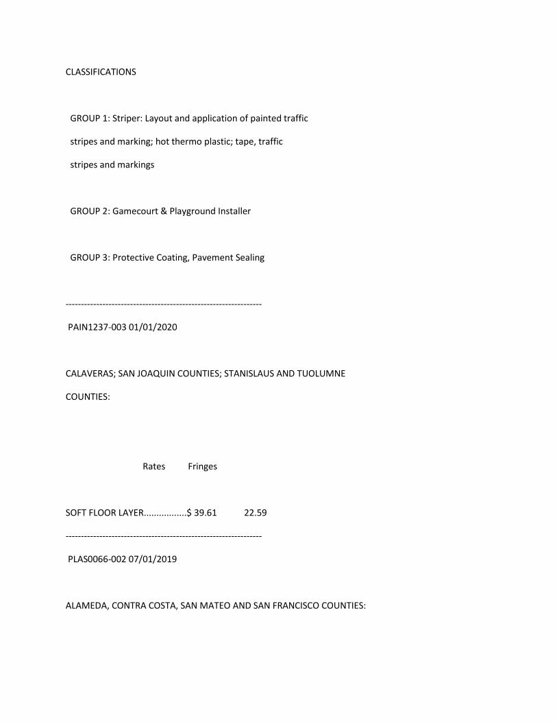
CLASSIFICATIONS
GROUP 1: Striper: Layout and application of painted traffic
stripes and marking; hot thermo plastic; tape, traffic
stripes and markings
GROUP 2: Gamecourt & Playground Installer
GROUP 3: Protective Coating, Pavement Sealing
----------------------------------------------------------------
PAIN1237-003 01/01/2020
CALAVERAS; SAN JOAQUIN COUNTIES; STANISLAUS AND TUOLUMNE
COUNTIES:
Rates Fringes
SOFT FLOOR LAYER.................$ 39.61 22.59
----------------------------------------------------------------
PLAS0066-002 07/01/2019
ALAMEDA, CONTRA COSTA, SAN MATEO AND SAN FRANCISCO COUNTIES:
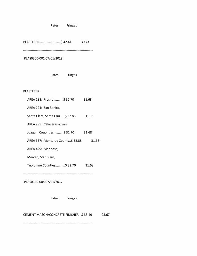
Rates Fringes
PLASTERER........................$ 42.41 30.73
----------------------------------------------------------------
PLAS0300-001 07/01/2018
Rates Fringes
PLASTERER
AREA 188: Fresno...........$ 32.70 31.68
AREA 224: San Benito,
Santa Clara, Santa Cruz.....$ 32.88 31.68
AREA 295: Calaveras & San
Joaquin Couonties...........$ 32.70 31.68
AREA 337: Monterey County..$ 32.88 31.68
AREA 429: Mariposa,
Merced, Stanislaus,
Tuolumne Counties...........$ 32.70 31.68
----------------------------------------------------------------
PLAS0300-005 07/01/2017
Rates Fringes
CEMENT MASON/CONCRETE FINISHER...$ 33.49 23.67
----------------------------------------------------------------
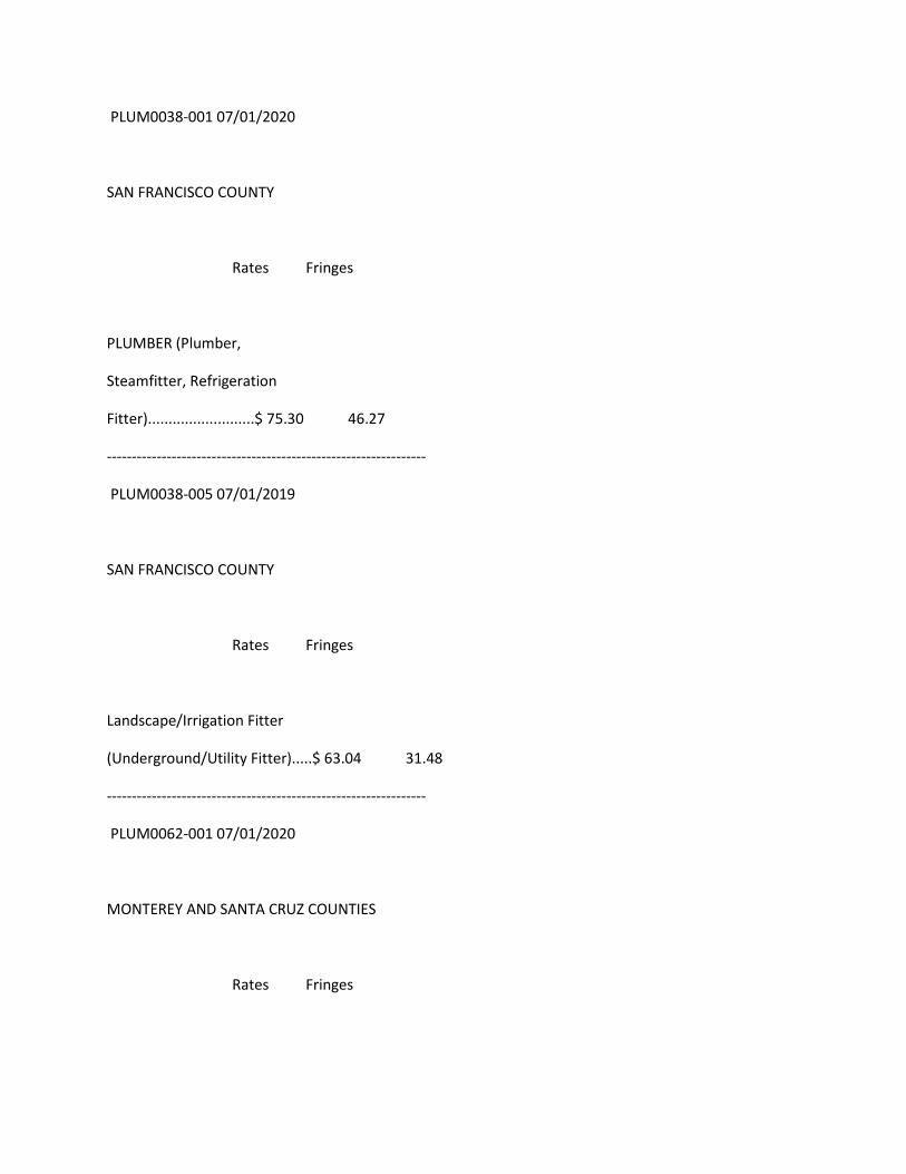
PLUM0038-001 07/01/2020
SAN FRANCISCO COUNTY
Rates Fringes
PLUMBER (Plumber,
Steamfitter, Refrigeration
Fitter)..........................$ 75.30 46.27
----------------------------------------------------------------
PLUM0038-005 07/01/2019
SAN FRANCISCO COUNTY
Rates Fringes
Landscape/Irrigation Fitter
(Underground/Utility Fitter).....$ 63.04 31.48
----------------------------------------------------------------
PLUM0062-001 07/01/2020
MONTEREY AND SANTA CRUZ COUNTIES
Rates Fringes
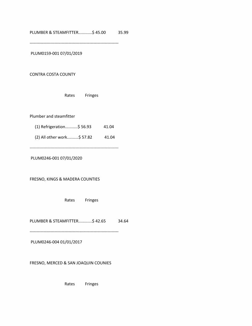
PLUMBER & STEAMFITTER............$ 45.00 35.99
----------------------------------------------------------------
PLUM0159-001 07/01/2019
CONTRA COSTA COUNTY
Rates Fringes
Plumber and steamfitter
(1) Refrigeration...........$ 56.93 41.04
(2) All other work..........$ 57.82 41.04
----------------------------------------------------------------
PLUM0246-001 07/01/2020
FRESNO, KINGS & MADERA COUNTIES
Rates Fringes
PLUMBER & STEAMFITTER............$ 42.65 34.64
----------------------------------------------------------------
PLUM0246-004 01/01/2017
FRESNO, MERCED & SAN JOAQUIN COUNIES
Rates Fringes
PLUMBER (PIPE TRADESMAN).........$ 13.00 10.74
PIPE TRADESMAN SCOPE OF WORK:
Installation of corrugated metal piping for drainage, as well
as installation of corrugated metal piping for culverts in
connection with storm sewers and drains; Grouting, dry
packing and diapering of joints, holes or chases including
paving over joints, in piping; Temporary piping for dirt
work for building site preparation; Operating jack hammers,
pavement breakers, chipping guns, concrete saws and spades
to cut holes, chases and channels for piping systems;
Digging, grading, backfilling and ground preparation for
all types of pipe to all points of the jobsite; Ground
preparation including ground leveling, layout and planting
of shrubbery, trees and ground cover, including watering,
mowing, edging, pruning and fertilizing, the breaking of
concrete, digging, backfilling and tamping for the
preparation and completion of all work in connection with
lawn sprinkler and landscaping; Loading, unloading and
distributing materials at jobsite; Putting away materials
in storage bins in jobsite secure storage area; Demolition
of piping and fixtures for remodeling and additions;
Setting up and tearing down work benches, ladders and job
shacks; Clean-up and sweeping of jobsite; Pipe wrapping and
waterproofing where tar or similar material is applied for
protection of buried piping; Flagman
----------------------------------------------------------------
PLUM0342-001 07/01/2018
ALAMEDA & CONTRA COSTA COUNTIES
Rates Fringes
PIPEFITTER
CONTRA COSTA COUNTY.........$ 58.68 42.40
PLUMBER, PIPEFITTER,
STEAMFITTER
ALAMEDA COUNTY..............$ 58.68 42.40
----------------------------------------------------------------
PLUM0355-004 07/01/2020
ALAMEDA, CALAVERAS, CONTRA COSTA, FRESNO, KINGS, MADERA,
MARIPOSA, MERCED, MONTEREY, SAN BENITO, SAN JOAQUIN, SAN MATEO,
SANTA CLARA, SANTA CRUZ, STANISLAUS, AND TUOLUMNE COUNTIES:
Rates Fringes
Underground Utility Worker
/Landscape Fitter...........$ 29.90 16.30
----------------------------------------------------------------
PLUM0393-001 07/01/2020
SAN BENITO AND SANTA CLARA COUNTIES
Rates Fringes
PLUMBER/PIPEFITTER...............$ 66.66 44.83
----------------------------------------------------------------
PLUM0442-001 07/01/2020
CALAVERAS, MARIPOSA, MERCED, SAN JOAQUIN, STANISLAUS & TUOLUMNE
COUNTIES
Rates Fringes
PLUMBER & STEAMFITTER............$ 45.50 31.89
----------------------------------------------------------------
PLUM0467-001 07/01/2020
SAN MATEO COUNTY
Rates Fringes
Plumber/Pipefitter/Steamfitter...$ 70.00 37.86
----------------------------------------------------------------
ROOF0027-002 01/01/2020
FRESNO, KINGS, AND MADERA COUNTIES
Rates Fringes
ROOFER...........................$ 31.11 14.41
FOOTNOTE: Work with pitch, pitch base of pitch impregnated
products or any material containing coal tar pitch, on any
building old or new, where both asphalt and pitchers are
used in the application of a built-up roof or tear off:
$2.00 per hour additional.
----------------------------------------------------------------
ROOF0040-002 08/01/2020
SAN FRANCISCO & SAN MATEO COUNTIES:
Rates Fringes
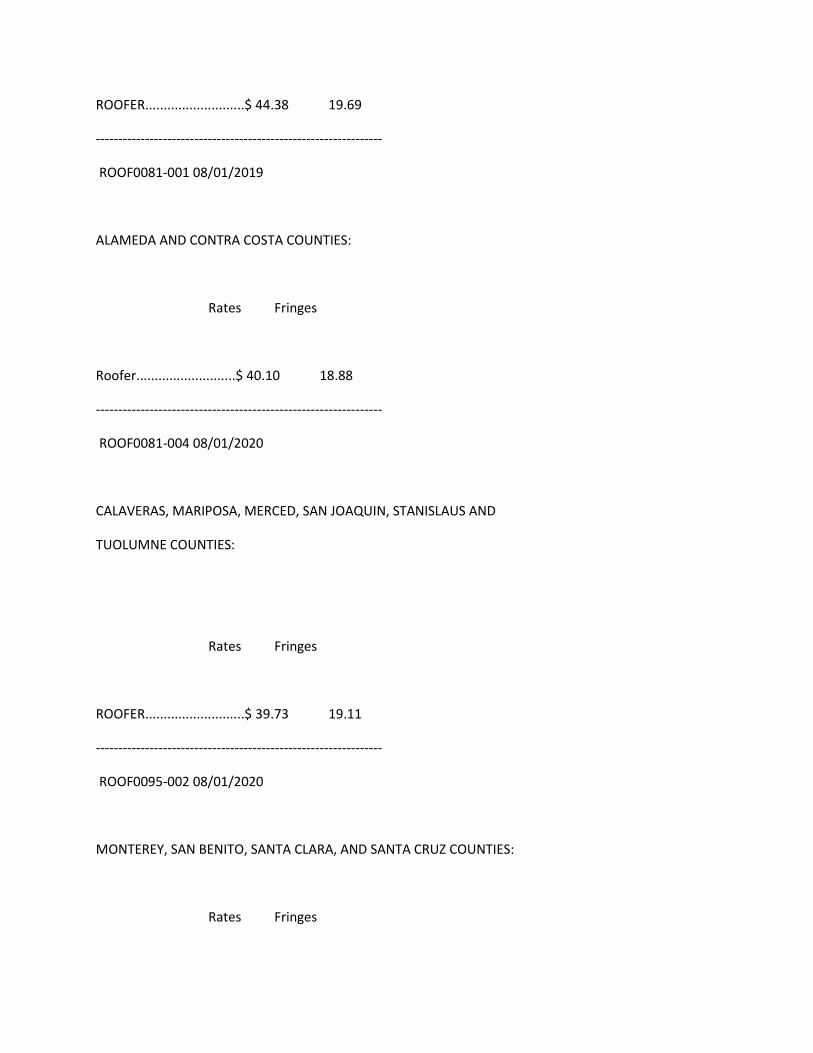
ROOFER...........................$ 44.38 19.69
----------------------------------------------------------------
ROOF0081-001 08/01/2019
ALAMEDA AND CONTRA COSTA COUNTIES:
Rates Fringes
Roofer...........................$ 40.10 18.88
----------------------------------------------------------------
ROOF0081-004 08/01/2020
CALAVERAS, MARIPOSA, MERCED, SAN JOAQUIN, STANISLAUS AND
TUOLUMNE COUNTIES:
Rates Fringes
ROOFER...........................$ 39.73 19.11
----------------------------------------------------------------
ROOF0095-002 08/01/2020
MONTEREY, SAN BENITO, SANTA CLARA, AND SANTA CRUZ COUNTIES:
Rates Fringes
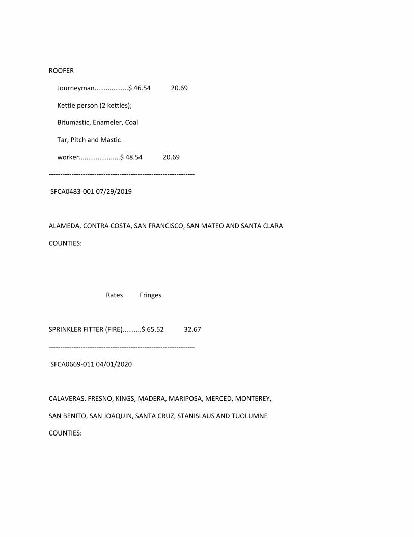
ROOFER
Journeyman..................$ 46.54 20.69
Kettle person (2 kettles);
Bitumastic, Enameler, Coal
Tar, Pitch and Mastic
worker......................$ 48.54 20.69
----------------------------------------------------------------
SFCA0483-001 07/29/2019
ALAMEDA, CONTRA COSTA, SAN FRANCISCO, SAN MATEO AND SANTA CLARA
COUNTIES:
Rates Fringes
SPRINKLER FITTER (FIRE)..........$ 65.52 32.67
----------------------------------------------------------------
SFCA0669-011 04/01/2020
CALAVERAS, FRESNO, KINGS, MADERA, MARIPOSA, MERCED, MONTEREY,
SAN BENITO, SAN JOAQUIN, SANTA CRUZ, STANISLAUS AND TUOLUMNE
COUNTIES:
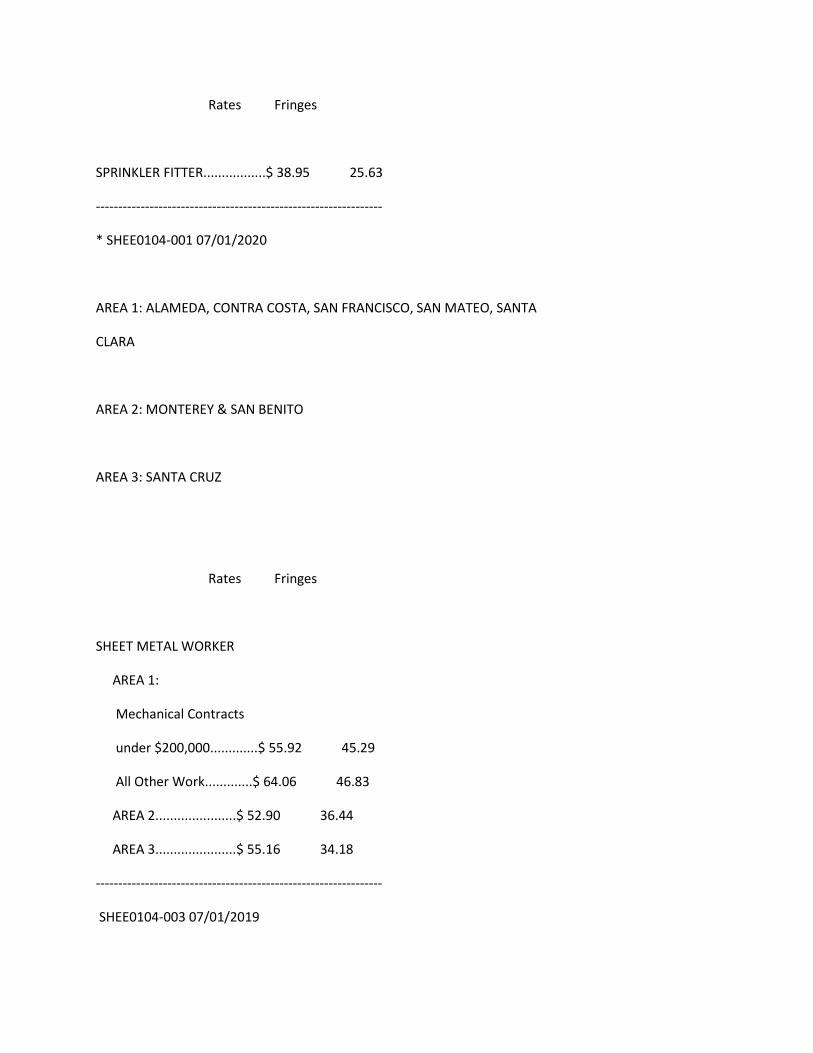
Rates Fringes
SPRINKLER FITTER.................$ 38.95 25.63
----------------------------------------------------------------
* SHEE0104-001 07/01/2020
AREA 1: ALAMEDA, CONTRA COSTA, SAN FRANCISCO, SAN MATEO, SANTA
CLARA
AREA 2: MONTEREY & SAN BENITO
AREA 3: SANTA CRUZ
Rates Fringes
SHEET METAL WORKER
AREA 1:
Mechanical Contracts
under $200,000.............$ 55.92 45.29
All Other Work.............$ 64.06 46.83
AREA 2......................$ 52.90 36.44
AREA 3......................$ 55.16 34.18
----------------------------------------------------------------
SHEE0104-003 07/01/2019
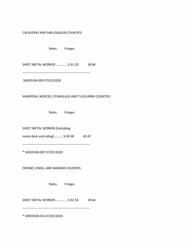
CALAVERAS AND SAN JOAQUIN COUNTIES:
Rates Fringes
SHEET METAL WORKER...............$ 41.20 36.84
----------------------------------------------------------------
SHEE0104-005 07/01/2020
MARIPOSA, MERCED, STANISLAUS AND TUOLUMNE COUNTIES:
Rates Fringes
SHEET METAL WORKER (Excluding
metal deck and siding)...........$ 40.38 43.47
----------------------------------------------------------------
* SHEE0104-007 07/01/2020
FRESNO, KINGS, AND MADERA COUNTIES:
Rates Fringes
SHEET METAL WORKER...............$ 42.53 39.64
----------------------------------------------------------------
* SHEE0104-015 07/01/2020
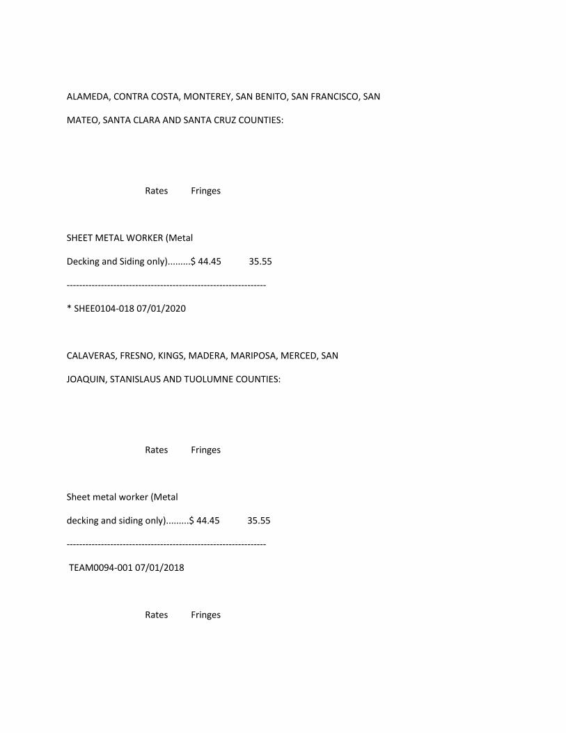
ALAMEDA, CONTRA COSTA, MONTEREY, SAN BENITO, SAN FRANCISCO, SAN
MATEO, SANTA CLARA AND SANTA CRUZ COUNTIES:
Rates Fringes
SHEET METAL WORKER (Metal
Decking and Siding only).........$ 44.45 35.55
----------------------------------------------------------------
* SHEE0104-018 07/01/2020
CALAVERAS, FRESNO, KINGS, MADERA, MARIPOSA, MERCED, SAN
JOAQUIN, STANISLAUS AND TUOLUMNE COUNTIES:
Rates Fringes
Sheet metal worker (Metal
decking and siding only).........$ 44.45 35.55
----------------------------------------------------------------
TEAM0094-001 07/01/2018
Rates Fringes
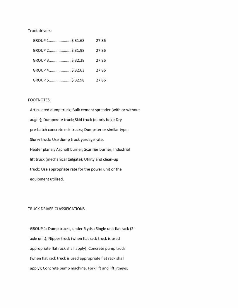
Truck drivers:
GROUP 1.....................$ 31.68 27.86
GROUP 2.....................$ 31.98 27.86
GROUP 3.....................$ 32.28 27.86
GROUP 4.....................$ 32.63 27.86
GROUP 5.....................$ 32.98 27.86
FOOTNOTES:
Articulated dump truck; Bulk cement spreader (with or without
auger); Dumpcrete truck; Skid truck (debris box); Dry
pre-batch concrete mix trucks; Dumpster or similar type;
Slurry truck: Use dump truck yardage rate.
Heater planer; Asphalt burner; Scarifier burner; Industrial
lift truck (mechanical tailgate); Utility and clean-up
truck: Use appropriate rate for the power unit or the
equipment utilized.
TRUCK DRIVER CLASSIFICATIONS
GROUP 1: Dump trucks, under 6 yds.; Single unit flat rack (2-
axle unit); Nipper truck (when flat rack truck is used
appropriate flat rack shall apply); Concrete pump truck
(when flat rack truck is used appropriate flat rack shall
apply); Concrete pump machine; Fork lift and lift jitneys;
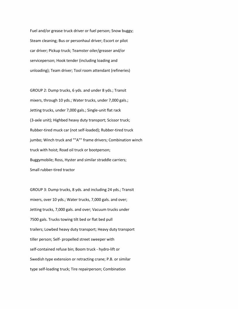
Fuel and/or grease truck driver or fuel person; Snow buggy;
Steam cleaning; Bus or personhaul driver; Escort or pilot
car driver; Pickup truck; Teamster oiler/greaser and/or
serviceperson; Hook tender (including loading and
unloading); Team driver; Tool room attendant (refineries)
GROUP 2: Dump trucks, 6 yds. and under 8 yds.; Transit
mixers, through 10 yds.; Water trucks, under 7,000 gals.;
Jetting trucks, under 7,000 gals.; Single-unit flat rack
(3-axle unit); Highbed heavy duty transport; Scissor truck;
Rubber-tired muck car (not self-loaded); Rubber-tired truck
jumbo; Winch truck and ""A"" frame drivers; Combination winch
truck with hoist; Road oil truck or bootperson;
Buggymobile; Ross, Hyster and similar straddle carriers;
Small rubber-tired tractor
GROUP 3: Dump trucks, 8 yds. and including 24 yds.; Transit
mixers, over 10 yds.; Water trucks, 7,000 gals. and over;
Jetting trucks, 7,000 gals. and over; Vacuum trucks under
7500 gals. Trucks towing tilt bed or flat bed pull
trailers; Lowbed heavy duty transport; Heavy duty transport
tiller person; Self- propelled street sweeper with
self-contained refuse bin; Boom truck - hydro-lift or
Swedish type extension or retracting crane; P.B. or similar
type self-loading truck; Tire repairperson; Combination
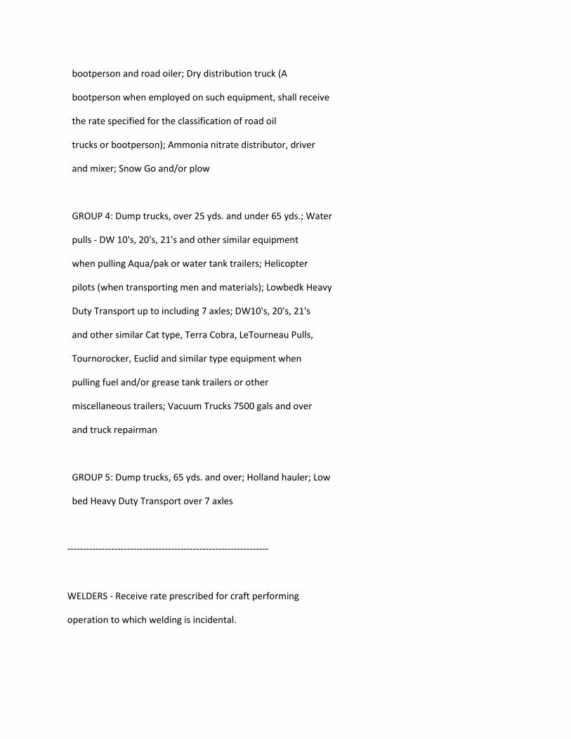
bootperson and road oiler; Dry distribution truck (A
bootperson when employed on such equipment, shall receive
the rate specified for the classification of road oil
trucks or bootperson); Ammonia nitrate distributor, driver
and mixer; Snow Go and/or plow
GROUP 4: Dump trucks, over 25 yds. and under 65 yds.; Water
pulls - DW 10's, 20's, 21's and other similar equipment
when pulling Aqua/pak or water tank trailers; Helicopter
pilots (when transporting men and materials); Lowbedk Heavy
Duty Transport up to including 7 axles; DW10's, 20's, 21's
and other similar Cat type, Terra Cobra, LeTourneau Pulls,
Tournorocker, Euclid and similar type equipment when
pulling fuel and/or grease tank trailers or other
miscellaneous trailers; Vacuum Trucks 7500 gals and over
and truck repairman
GROUP 5: Dump trucks, 65 yds. and over; Holland hauler; Low
bed Heavy Duty Transport over 7 axles
----------------------------------------------------------------
WELDERS - Receive rate prescribed for craft performing
operation to which welding is incidental.

================================================================
Note: Executive Order (EO) 13706, Establishing Paid Sick Leave
for Federal Contractors applies to all contracts subject to the
Davis-Bacon Act for which the contract is awarded (and any
solicitation was issued) on or after January 1, 2017. If this
contract is covered by the EO, the contractor must provide
employees with 1 hour of paid sick leave for every 30 hours
they work, up to 56 hours of paid sick leave each year.
Employees must be permitted to use paid sick leave for their
own illness, injury or other health-related needs, including
preventive care; to assist a family member (or person who is
like family to the employee) who is ill, injured, or has other
health-related needs, including preventive care; or for reasons
resulting from, or to assist a family member (or person who is
like family to the employee) who is a victim of, domestic
violence, sexual assault, or stalking. Additional information
on contractor requirements and worker protections under the EO
is available at www.dol.gov/whd/govcontracts.
Unlisted classifications needed for work not included within
the scope of the classifications listed may be added after
award only as provided in the labor standards contract clauses
(29CFR 5.5 (a) (1) (ii)).
----------------------------------------------------------------
The body of each wage determination lists the classification
and wage rates that have been found to be prevailing for the
cited type(s) of construction in the area covered by the wage
determination. The classifications are listed in alphabetical
order of ""identifiers"" that indicate whether the particular
rate is a union rate (current union negotiated rate for local),
a survey rate (weighted average rate) or a union average rate
(weighted union average rate).
Union Rate Identifiers
A four letter classification abbreviation identifier enclosed
in dotted lines beginning with characters other than ""SU"" or
""UAVG"" denotes that the union classification and rate were
prevailing for that classification in the survey. Example:
PLUM0198-005 07/01/2014. PLUM is an abbreviation identifier of
the union which prevailed in the survey for this
classification, which in this example would be Plumbers. 0198
indicates the local union number or district council number
where applicable, i.e., Plumbers Local 0198. The next number,
005 in the example, is an internal number used in processing
the wage determination. 07/01/2014 is the effective date of the
most current negotiated rate, which in this example is July 1,
2014.
Union prevailing wage rates are updated to reflect all rate
changes in the collective bargaining agreement (CBA) governing
this classification and rate.
Survey Rate Identifiers
Classifications listed under the ""SU"" identifier indicate that
no one rate prevailed for this classification in the survey and
the published rate is derived by computing a weighted average
rate based on all the rates reported in the survey for that
classification. As this weighted average rate includes all
rates reported in the survey, it may include both union and
non-union rates. Example: SULA2012-007 5/13/2014. SU indicates
the rates are survey rates based on a weighted average
calculation of rates and are not majority rates. LA indicates
the State of Louisiana. 2012 is the year of survey on which
these classifications and rates are based. The next number, 007
in the example, is an internal number used in producing the
wage determination. 5/13/2014 indicates the survey completion
date for the classifications and rates under that identifier.
Survey wage rates are not updated and remain in effect until a
new survey is conducted.
Union Average Rate Identifiers
Classification(s) listed under the UAVG identifier indicate
that no single majority rate prevailed for those
classifications; however, 100% of the data reported for the
classifications was union data. EXAMPLE: UAVG-OH-0010
08/29/2014. UAVG indicates that the rate is a weighted union
average rate. OH indicates the state. The next number, 0010 in
the example, is an internal number used in producing the wage
determination. 08/29/2014 indicates the survey completion date
for the classifications and rates under that identifier.
A UAVG rate will be updated once a year, usually in January of
each year, to reflect a weighted average of the current
negotiated/CBA rate of the union locals from which the rate is
based.
----------------------------------------------------------------
WAGE DETERMINATION APPEALS PROCESS
1.) Has there been an initial decision in the matter? This can
be:
* an existing published wage determination
* a survey underlying a wage determination
* a Wage and Hour Division letter setting forth a position on
a wage determination matter
* a conformance (additional classification and rate) ruling
On survey related matters, initial contact, including requests
for summaries of surveys, should be with the Wage and Hour
Regional Office for the area in which the survey was conducted
because those Regional Offices have responsibility for the
Davis-Bacon survey program. If the response from this initial
contact is not satisfactory, then the process described in 2.)
and 3.) should be followed.
With regard to any other matter not yet ripe for the formal
process described here, initial contact should be with the
Branch of Construction Wage Determinations. Write to:
Branch of Construction Wage Determinations
Wage and Hour Division
U.S. Department of Labor
200 Constitution Avenue, N.W.
Washington, DC 20210
2.) If the answer to the question in 1.) is yes, then an
interested party (those affected by the action) can request
review and reconsideration from the Wage and Hour Administrator
(See 29 CFR Part 1.8 and 29 CFR Part 7). Write to:
Wage and Hour Administrator
U.S. Department of Labor
200 Constitution Avenue, N.W.
Washington, DC 20210
The request should be accompanied by a full statement of the
interested party's position and by any information (wage
payment data, project description, area practice material,
etc.) that the requestor considers relevant to the issue.
3.) If the decision of the Administrator is not favorable, an
interested party may appeal directly to the Administrative
Review Board (formerly the Wage Appeals Board). Write to:
Administrative Review Board
U.S. Department of Labor
200 Constitution Avenue, N.W.
Washington, DC 20210
4.) All decisions by the Administrative Review Board are final.
================================================================
END OF GENERAL DECISION"

Injection Wells Phase 3Mandatory Pre-Bid Meeting
9/17/2020 9:00
Name Company Zoom Site Tour 9/17/2020 Site Tour 9/30/2020Gabriela Raya Monterey Peninsula Engineering [email protected] Yes YesAaron Ellis Anderson Pacific Engineering [email protected] YesGary Barber Anderson Pacific Engineering [email protected] Yes YesPete Anderson Anderson Pacific Engineering [email protected] YesGlen Lamoreaux Mountain Cascade Inc. [email protected] Yes YesAlbert Vasquez Nor-Cal Pump & Well Drilling [email protected] Yes YesMark Jorgenson Pacific Infrastructure [email protected] Yes YesRoss Wickes Anvil Builders [email protected] Yes YesWes Lockard Pacific Coast West Well Drilling [email protected] Yes YesChelsea Borneman Pacific Coast West Well Drilling chelsea@pcwelldrilling. YesTom Seidel Specialty Construction, Inc [email protected] Yes YesRyan Coffin Capital Flow [email protected] YesBrian Zimmerer Zim Industries [email protected] Yes YesScott Turner PCL Construction [email protected] Yes