Embed Size (px)
Citation preview
DD - 1
Section
Amplifier Description and Operation
- Amplifier Description- Indicator LED’s- Signal Inputs & Outputs- Amplifier Feature Description- Setting the Amplifier
Section D - Amplifier Description and Operation
Rock-Ola Mfg. Corp. Operation & Service Manual
DA-8 Bubbler
D - 2
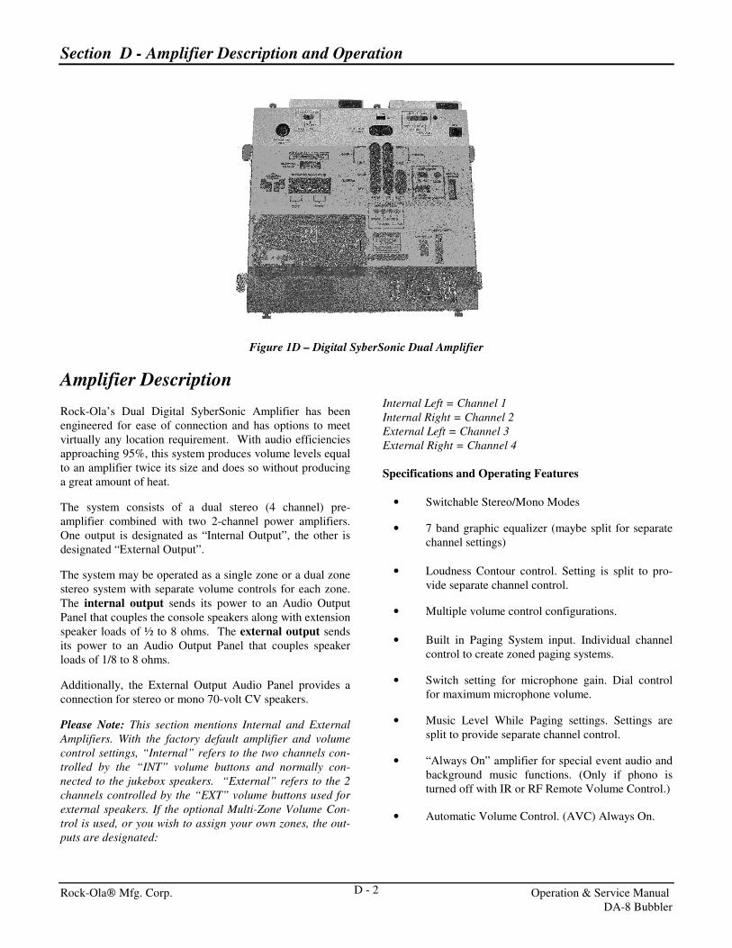
Figure 1D – Digital SyberSonic Dual Amplifier
Amplifier Description
Rock-Ola’s Dual Digital SyberSonic Amplifier has been
engineered for ease of connection and has options to meet
virtually any location requirement. With audio efficiencies
approaching 95%, this system produces volume levels equal
to an amplifier twice its size and does so without producing
a great amount of heat.
The system consists of a dual stereo (4 channel) pre-
amplifier combined with two 2-channel power amplifiers.
One output is designated as “Internal Output”, the other is
designated “External Output”.
The system may be operated as a single zone or a dual zone
stereo system with separate volume controls for each zone.
The internal output sends its power to an Audio Output
Panel that couples the console speakers along with extension
speaker loads of ½ to 8 ohms. The external output sends
its power to an Audio Output Panel that couples speaker
loads of 1/8 to 8 ohms.
Additionally, the External Output Audio Panel provides a
connection for stereo or mono 70-volt CV speakers.
Please Note: This section mentions Internal and External
Amplifiers. With the factory default amplifier and volume
control settings, “Internal” refers to the two channels con-
trolled by the “INT” volume buttons and normally con-
nected to the jukebox speakers. “External” refers to the 2
channels controlled by the “EXT” volume buttons used for
external speakers. If the optional Multi-Zone Volume Con-
trol is used, or you wish to assign your own zones, the out-
puts are designated:
Internal Left = Channel 1
Internal Right = Channel 2
External Left = Channel 3
External Right = Channel 4
Specifications and Operating Features
• Switchable Stereo/Mono Modes
• 7 band graphic equalizer (maybe split for separate
channel settings)
• Loudness Contour control. Setting is split to pro-
vide separate channel control.
• Multiple volume control configurations.
• Built in Paging System input. Individual channel
control to create zoned paging systems.
• Switch setting for microphone gain. Dial control
for maximum microphone volume.
• Music Level While Paging settings. Settings are
split to provide separate channel control.
• “Always On” amplifier for special event audio and
background music functions. (Only if phono is
turned off with IR or RF Remote Volume Control.)
• Automatic Volume Control. (AVC) Always On.

Section D - Amplifier Description and Operation
Rock-Ola Mfg. Corp. Operation & Service Manual
DA-8 Bubbler
D - 3
Plug-in RCA Type Connectors for:
AUX BGM - Input with automatic switching and pro-
grammable minimum/maximum volume settings.
Fixed Output - line level output directly from the core.
Int/Ext Output - 4 channel pre-amp outputs. Signal
level is variable with volume control settings.
Indicator LED’s
The Digital SyberSonic Amplifier has LED’s to give a vis-
ual indication of its operating condition and status. The
LED’s and their functions are as follows:
Power - When lit, indicates the amplifier has power.
Status - Indicates when the paging system (micro-
phone) is active.
Steady On - Normal operation. Paging system is avail-
able.
Flashing - Paging system is in use.
COM - Indicates when amplifier receives instructions from
the jukeboxes Core unit.
Always Off - Indicates a communication fault between
the amplifier and Core Unit.
Single One Second Flash on Power Up - Processor is
running.
Steady On - Normal operation. Setup instructions re-
ceived and installed.
Intermittent Flashing - Amplifier is receiving instruc-
tions from Jukebox Core Unit.
Overload - When lit, indicates the amp is muted or a
speaker overload condition exists.
Signal Inputs and Outputs
The Digital SyberSonic Amplifier has five (5) sets of RCA
type jacks located at its upper right corner.
Figure 2D – RCA Jacks
Each set of connectors have separate functions, they are:
CD In - This connection is the analog audio signal that is
being fed directly from the Core unit Audio Output into the
amplifier.
Fixed Out - This connection is the unconditioned analog
audio output from the Core unit.
BGM In - This connection allows the input of a low level
signal (maximum 1 volt RMS) from another audio source
(such as a tape player, TV or FM tuner) to be fed into the
amplifier for aux background music amplification. The sig-
nal volume level is limited via software setting Set Back-
ground Music Play Levels.
Note: This amplifier is designed to automatically switch
between the AUX BGM and CD inputs where the CD input
always takes priority.
WARNING Do not connect the AUX BGM Inputs
to the speaker outputs of a receiver or
power amp as this will damage the
jukebox amplifier and void its war-
ranty.
Int Out - Left & Right - These connections are a variable
level output signal directly from the internal pre-amp. In the
default configuration, the signal level follows the internal
volume control. If the optional Multi-Zone Volume Control
is used, channels 1 and 2 control these signal levels respec-
tively. Output signal level may be limited via software con-
trol in Amplifier Output Volume and Limits.
Ext Out - Left & Right - These connections are a variable
level output signal directly from the external pre-amp. In the
default configuration, the signal level follows the external
volume control. If the optional Multi-Zone Volume Control
is used, channels 3 and 4 control these signal levels respec-
tively. Output signal level may be limited via software con-
trol in Amplifier Output Volume and Limits.
Amplifier Feature Descriptions
Your Digital SyberSonic Amplifier is preset at the factory
for optimum operation; however some adjustment may be
required to achieve the best sound or operating features for
your particular environment. For ease of use, amplifier fea-
tures are set or adjusted via the jukeboxes touch screen.
Setting Instructions are found in the section titled “Set-
ting the Amplifier” later in this chapter.
AVC Control - The Digital SyberSonic Amplifier uses
software to limit the difference between loud and soft re-
cordings (dynamic range). Automatic Volume Control
(AVC) will retain the dynamic range of the recording, just

Section D - Amplifier Description and Operation
Rock-Ola Mfg. Corp. Operation & Service Manual
DA-8 Bubbler
D - 4
reduce it. The effect is that the music sounds natural but
songs with loud passages are only slightly louder. AVC also
controls the BGM IN signal. Note: This feature may not be
turned off.
Equalizer – This changes speaker tone by decreasing the
response (gain) of a particular frequency range. Each of the
4 possible zones/channels may have separate settings.
Balance – Set the channel balance by increasing or decreas-
ing its volume level, as compared to the other, then link one
channel to the other. See Setting The Amplifier for Instruc-
tions
Music Level While Paging (MLWP) - Mic and Paging
Parameters – This setting changes how much of the music
is heard when using a microphone for paging while music is
playing. Each channel has separate settings. The music level
is a percentage of the current volume. Choices are 0% to
100% in increments of 10% and On or Off where Off de-
feats paging for that channel.
Loudness – This setting allows you to turn on or off the
loudness contour enhancement for the each channel sepa-
rately. The Loudness Contour enhances bass output at lower
volume levels.
Volume Limits – The Digital SyberSonic amplifiers can
have their volumes set to minimum and maximum levels.
Each channel may be set separately in both Normal Play and
Background Music Modes.
Volume Control (zone) Linking – There may be times
when you do not want a location to have separate control of
the internal and external amplifier. Or perhaps you want two
or more areas to have separate volume controls. Syber-
Sonic’s advanced electronics system allows the “linking” of
its volume controls.
When linked, pressing either the Internal or External buttons
will the cause the linked channels volume to change. Also
when linked, the system will maintain the set balance, thus
eliminating the need to “tap” the speakers. Setting informa-
tion is in the “Setting The Amplifier” section.
Setting The Amplifier
The graphic equalizer, channel volume linkages, and other
features are adjusted via the jukebox touch screen with set-
tings represented by a graphic.
Section E of this manual contains specific instructions for
accessing and using the Service Console. The following
section will only give instructions for items that pertain to
the audio system.
To set the amplifier features, access the Service Console by
opening the dome or, if the dome is already opened, cycle
the Service Switch. The following screen will appear:
Fig. 3D
Touch System Settings and Diagnostics >
Fig. 4D
Touch Configure Audio Amplifier >

Section D - Amplifier Description and Operation
Rock-Ola Mfg. Corp. Operation & Service Manual
DA-8 Bubbler
D - 5
Fig. 5D
Touch the desired feature then “program the amp” in the
same way that all other programming is done. To exit a
screen, touch the Back button. To completely exit the Ser-
vice Console, touch the Quit button.
For brevity, this section will assume the Service Console >
System Settings and Diagnostics screens have already
been accessed, therefore the instructions will show the touch
steps as Configure Audio Amplifier > desired feature>
setting.
Hint: Because these settings affect the sound, it is best to
play a few songs before accessing the Service Console so
that music will be playing and you can hear the changes.
Configure Paid Selection Volume
This screen is used to link channels to create zones and set
the Minimum, Current and Maximum Volumes for Paid
Selections. Touch Configure Audio Amplifier > Config-
ure Paid Selection Volume.
Fig. 6D
Set Paid Output Volume and Linkage – This sets the cur-
rent volume level, channel balance and volume zones.
Set Paid Output Volume Limits – This sets the Minimum
and Maximum allowable volume for each channel.
To set the current Paid Selection Volume or to assign
zones, touch Configure Audio Amplifier > Configure
Paid Selection Volume > Set Paid Output Volume and
Linkage.
Fig. 7D
To assign volume zones, you will link or unlink channels.
The Zone indicator will change automatically as you link or
unlink channels. The screen above shows the default, 2-zone
settings as used with the RF, IR and red (6 button) wired
volume control.
Internal Right Output = Channel 1
Internal Left Output = Channel 2
External Right Output = Channel 3
External Left Output = Channel 4
Hint: Before creating zones, unlink all channels, play a
song and set each channels volume so that the jukebox
and extension speakers are “balanced” to your liking.
Then link the desired channels to create your zones.
In this configuration, Channels 1&2 are linked to create
Zone 1 and Channels 3&4 are linked to create Zone 2.
When the INT volume buttons are pressed, Channels 1&2
(Internal L&R) change together. When the EXT volume
buttons are pressed, Channels 3&4 (External L&R) change
together. You may reassign which zone the INT and EXT
buttons control in the Two Channel Zone Assignments
Screen.
Several other installation scenarios are shown in Section C
of this manual.
Section D - Amplifier Description and Operation
Rock-Ola Mfg. Corp. Operation & Service Manual
DA-8 Bubbler
D - 6
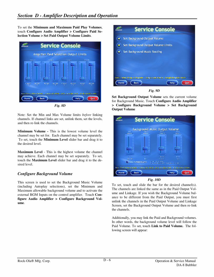
To set the Minimum and Maximum Paid Play Volumes,
touch Configure Audio Amplifier > Configure Paid Se-
lection Volume > Set Paid Output Volume Limits.
Fig. 8D
Note: Set the Min and Max Volume limits before linking
channels. If channel links are set, unlink them, set the levels,
and then re-link the channels.
Minimum Volume - This is the lowest volume level the
channel may be set for. Each channel may be set separately.
To set, touch the Minimum Level slider bar and drag it to
the desired level.
Maximum Level - This is the highest volume the channel
may achieve. Each channel may be set separately. To set,
touch the Maximum Level slider bar and drag it to the de-
sired level.
Configure Background Volume
This screen is used to set the Background Music Volume
(including Autoplay selections), set the Minimum and
Maximum allowable background volume and to activate the
external BGM Inputs on the control amplifier. Touch Con-
figure Audio Amplifier > Configure Background Vol-
ume.
Fig. 9D
Set Background Output Volume sets the current volume
for Background Music. Touch Configure Audio Amplifier
> Configure Background Volume > Set Background
Output Volume
Fig. 10D
To set, touch and slide the bar for the desired channel(s).
The channels are linked the same as in the Paid Output Vol-
ume and Linkage. If you wish the Background Volume bal-
ance to be different from the Paid Output, you must first
unlink the channels in the Paid Output Volume and Linkage
Screen, set the Background Output Volume and then re-link
the channels.
Additionally, you may link the Paid and Background volumes.
In other words, the background volume level will follow the
Paid Volume. To set, touch Link to Paid Volume. The fol-
lowing screen will appear:

Section D - Amplifier Description and Operation
Rock-Ola Mfg. Corp. Operation & Service Manual
DA-8 Bubbler
D - 7
Fig. 11D
To set, choose a percentage of the paid volume you wish the
background music to play at.
Set Background Output Volume Limits configures the
Minimum and Maximum Output Volume for Background
Music. Touch Configure Audio Amplifier > Configure
Background Volume > Set Background Output Volume
Limits
Fig. 12D
Note: Set the Min and Max Volume limits before linking
channels. If channel links are set, unlink them, set the levels,
and then re-link the channels.
Minimum Volume - This is the lowest volume level the
channel may be set for. Each channel may be set separately.
To set, touch the Minimum Level slider bar and drag it to
the desired level.
Maximum Level - This is the highest volume the channel
may achieve. Each channel may be set separately. To set,
touch the Maximum Level slider bar and drag it to the de-
sired level.
Set Background Music Routing configures whether or not
the BGM Input jacks will be active when the jukebox is not
playing a selection. Touch Configure Audio Amplifier >
Configure Background Volume > Set Background Music
Routing
Fig. 13D
Background Music Routing while power is ON. Check
External BGM Inputs if you want the BGM Inputs of the
amplifier to be live when no paid selections or autoplay se-
lections are in play.
Background Music Routing while power is OFF. Check
external BGM Inputs if you want the BGM Inputs of the
amplifier to be live when the cabinet power is off.
Set Equalizers
This screen is used to set the speaker tone. Touch Set Au-
dio Amplifier > Set Equalizers. Each zone (as set up in
the Paid Play Output and Linkage Screen) may be set sepa-
rately. Frequency ranges from left to right include Bass,
Midrange and Treble. This arrangement allows precise tone
settings for each area of the venue.
Fig. 14D

Section D - Amplifier Description and Operation
Rock-Ola Mfg. Corp. Operation & Service Manual
DA-8 Bubbler
D - 8
To set equalizers, first choose which zone to change by
touching the Selected Output Channel window down ar-
row then, using the up or down arrows, find the desired
zone. Touch the window again to lock it in.
To set the tone, touch and drag the slider bar for the desired
frequency range. Repeat the same process for each fre-
quency range until the desired tone achieved.
Note: The equalizers are frequency cut filters. Setting all
ranges to full will result in a flat frequency response. If you
desire more bass, set the 60Hz and 100Hz bars higher and
the rest of the bars lower.
Loudness, Mic and Paging
This screen is used to set the loudness contour (Audio En-
hancement at lower volumes) and paging microphone pa-
rameters. Touch Configure Audio Amplifier > Loudness
Mic and Paging.
Fig. 15D
Reset Factory Defaults
You may restore the amplifier settings back to their original
factory defaults. To do so, touch Configure Audio Ampli-
fier > Reset Factory Defaults. Then touch Reset Now.
Fig. 16D
Set Amplifier Loudness turns the loudness contour on or
off. Touch Configure Audio Amplifier > Loudness, Mic
and Paging > Set Amplifier Loudness
Fig. 17D
Amplifier Loudness - Channels are set separately. Touch
On or Off button.
Set Mic and Paging Parameters - This screen is used to
set the Music Level While Paging and turn on or off paging
for a particular channel. Touch Configure Audio Ampli-
fier > Loudness, Mic and Paging > Set Mic and Paging
Parameters. Channels are set separately.

Section D - Amplifier Description and Operation
Rock-Ola Mfg. Corp. Operation & Service Manual
DA-8 Bubbler
D - 9
Fig. 18D
Music Level - To set the Music Level while Paging, touch
the down arrow in the desired channel’s window then, using
the up or down arrow, find the desired setting. Touch the
channel’s window again to lock in the setting.
Page On - Page Off - Use this feature to create a “zoned”
paging system. To change Page On - Page Off, touch the
desired setting for the appropriate channel.
Two Channel Zone Assignments sets which zone the
IR, RF and Red (6 button) Volume Control’s INT and EXT
buttons will be in command of. Touch Configure Audio
Amplifier > Two Channel Zone Assignment.
Fig. 19D
RF / IR / 2 Channel Wired “Internal” sets which zone the
volume control’s INT buttons will regulate.
RF /IR / 2 Channel Wired “External” sets which zone the
volume control’s EXT buttons will regulate.
Note: You may assign the INT and EXT buttons to any zone
as configured in Set Paid Output Volume and Linkage, but
keep in mind that only two zones may be controlled. To con-
trol the volume of more than two zones, the optional Multi-
Zone Volume Control must be used.
Volume Control Options
In addition to audio settings, the Service Console has set-
tings for Volume Control behavior. To access, from the
Service Console, touch System Settings and Diagnostics >
Configure Remote Controls.
Fig. 20D
Touch the desired option. The display will change to the
appropriate screen.
Configure Pause/Mute Behavior
Use this screen to set how the Mute button behaves. Touch
Configure Remote Controls > Configure Remote
Pause/Mute Behavior. You may choose from Persistent
(stays muted until the mute button is pressed again) or
Timed. A green button with a checkmark indicates which
option is active.
Fig. 21D
Section D - Amplifier Description and Operation
Rock-Ola Mfg. Corp. Operation & Service Manual
DA-8 Bubbler
D - 10
To set, touch the desired option. If “Timed” is chosen you
must set the amount of Pause time.
To set the Pause Time, touch the down arrow then, using the
up or down arrows, find the desired time. Once your choice
is found, touch the time window to lock in your setting.
Configure Remote Credit Pool
Use this screen to allow the location to put credits on the
jukebox with the remote control star (*) button. Touch Con-
figure Remote Controls > Configure Remote Credit
Pool. Choose unlimited or limited credits. If limited is cho-
sen, a “pool” of credits is created. Select how many credits
to make available in the box. There are also buttons to clear
the credit pool and reset the pool to the number selected
above. NOTE: Selections made with free credits are treated
as “Free Plays” as described in the Ecast Operator Agree-
ment.
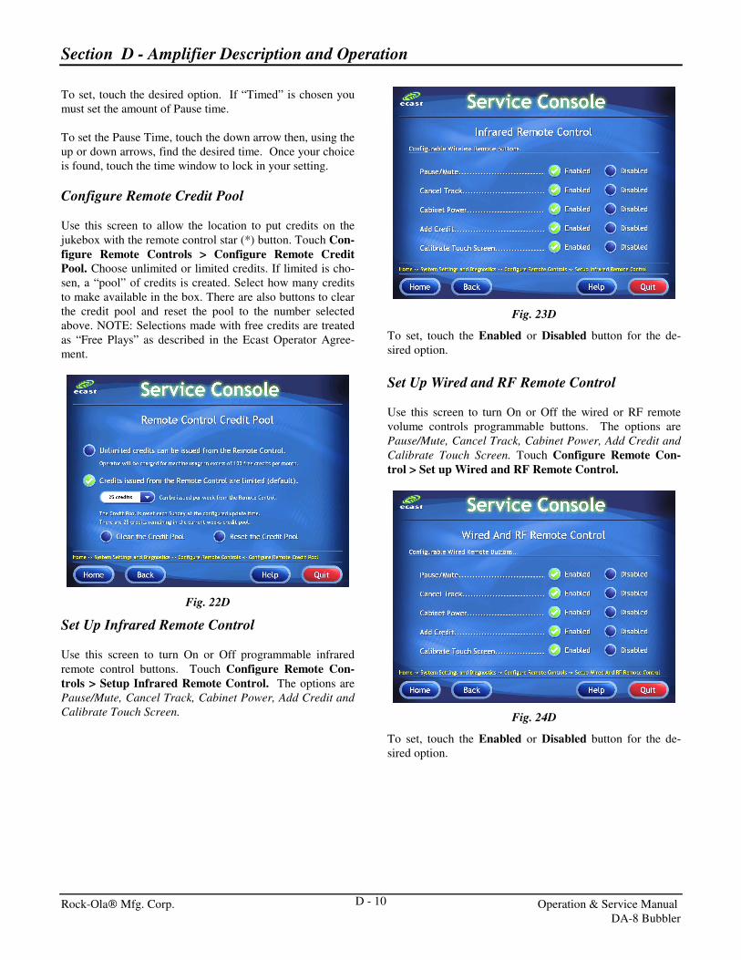
Fig. 22D
Set Up Infrared Remote Control
Use this screen to turn On or Off programmable infrared
remote control buttons. Touch Configure Remote Con-
trols > Setup Infrared Remote Control. The options are
Pause/Mute, Cancel Track, Cabinet Power, Add Credit and
Calibrate Touch Screen.
Fig. 23D
To set, touch the Enabled or Disabled button for the de-
sired option.
Set Up Wired and RF Remote Control
Use this screen to turn On or Off the wired or RF remote
volume controls programmable buttons. The options are
Pause/Mute, Cancel Track, Cabinet Power, Add Credit and
Calibrate Touch Screen. Touch Configure Remote Con-
trol > Set up Wired and RF Remote Control.
Fig. 24D
To set, touch the Enabled or Disabled button for the de-
sired option.