Embed Size (px)
Citation preview

Secret-Focus: A Practical Physical Layer SecretCommunication System by Perturbing Focused
Phases in Distributed BeamformingXiaoran Fan1, Zhijie Zhang1, Wade Trappe1, Yanyong Zhang1, Rich Howard1, and Zhu Han2
1Wireless Information Network Laboratory, Rutgers University, USA2Department of Electrical and Computer Engineering, University of Houston, USA
Abstract— Ensuring confidentiality of communication is fun-damental to securing the operation of a wireless system, whereeavesdropping is easily facilitated by the broadcast nature of thewireless medium. By applying distributed beamforming amonga coalition, we show that a new approach for assuring physicallayer secrecy, without requiring any knowledge about the eaves-dropper or injecting any additional cover noise, is possible if thetransmitters frequently perturb their phases around the properalignment phase while transmitting messages. This approach isreadily applied to amplitude-based modulation schemes, suchas PAM or QAM. We present our secrecy mechanisms, proveseveral important secrecy properties, and develop a practicalsecret communication system design. We further implement anddeploy a prototype that consists of 16 distributed transmittersusing USRP N210s in a 20× 20× 3 m3 area. By sending morethan 160M bits over our system to the receiver, depending onsystem parameter settings, we measure that the eavesdroppersfailed to decode 30% − 60% of the bits cross multiple locationswhile the intended receiver has an estimated bit error ratio of3× 10−6.
Index Terms—Secret communication, distributed beamform-ing, physical layer security
I. INTRODUCTION
Ensuring confidentiality of communication links is amongthe most fundamental objectives in developing communicationsystems. It is crucial for many applications to be able todistribute secure bit strings, such as higher-layer encryptionkeys, to wireless entities. Providing confidentiality is often adaunting task due to the broadcast nature of wireless links andtherefore the ease of eavesdropping.
In addition to cryptographic mechanisms, many mechanismsthat exploit a communication system’s physical layer proper-ties to protec secrecy have been proposed. These mechanismsusually aim to make the channel to the intended receiver muchbetter than the channel to the eavesdropper. For example,wireless signal’s propagation and fading properties have beenexploited to increase capacity and enhance security in [1],[2], [3], [4]. Beamforming has been leveraged to increasethe signal to noise ratio (SNR) at the intended receiver aswell as to minimize the SNR for the eavesdropper usingzero-forcing [5]. Artificial noise has been targeted at theeavesdropper to jam their reception [6]. Though these systemshave demonstrated capabilities to communicate secretly, theyhave several drawbacks. Firstly, most of them assume that
the eavesdropper’s location is known, and there are only asmall number (often just one) eavesdropper. Secondly, thepracticality and efficient distribution of the secret in theseproposed systems is questionable. Thirdly, many systems haveshadow areas where the anti-eavesdropping mechanism is lesseffective. Fourthly, some systems assume the eavesdropperspossess less knowledge than the receiver. Therefore, support-ing confidentiality remains a significant challenge in wirelesscommunication systems.
Recently, distributed communication systems that involve adistributed collection of transmitters have received attention inthe community. For example, a cellular provider may employmultiple basestations that are connected by dedicated back-haul. At the other end, it could just be a group of transmitterswho are willing to coordinate their transmissions to a commonreceiver [7], [8]. In such systems, referred as distributedbeamforming [9], the transmitters can form a coalition andachieve constructive superpositioning of signals at the intendedreceiver by aligning the received signals’ phases, with thereceiver sending a small amount of feedback. In this study, werefer to this type of distributed systems as distributed phasealignment systems and leverage such a system to facilitatesecret communication.
By examining how the transmitter signals coherently com-bine at the receiver, we show that phase alignment accom-plishes highly efficient secret communication against eaves-droppers without knowing their location, nor introducing anyadditional signal/noise. Also, to engage in secret communi-cation, a distributed phase alignment system only needs tointroduce very minor modifications to their normal transmis-sion procedure. Once the transmitters align their phases atthe receiver, they may start to communicate secretly to thereceiver, by periodically dithering its phase around the properalignment phase during transmission. In this way, the systemnaturally achieves secret communication. Firstly, the secretrecipient’s SNR is largely increased by aligning the phasesat the intended recipient. Slight dithering of the phases lateron has negligible impact on the alignment, but can create highreceived signal strength (RSS) variation at other locations, hin-dering anyone else from decoding the signal. Thirdly, it doesnot involve using interference for secrecy, which complicatessystem design, requires complex interference cancellation and
decoding, and regulations suggest is unlikely to be allowed inpractical systems. We refer to this highly efficient yet practicalsecret communication mechanism as Secret-Focus.
In this paper, we show the effectiveness of Secret-Focusthrough both analysis and prototyping (using N210 USRPs).Our experimental results show that the intended recipienthas bit error ratio (BER) as low as 3 × 10⁻⁶ while eaves-droppers have a much higher BER ranging from 31% to38%, from measuring different eavesdropper locations for atotal of 164.79M bits. In addition to the main test area, wehave also examined extreme eavesdropper locations to furtherdemonstrate it has little shadow area. We show that whenthe eavesdropper antenna is side by side(approx. 1cm) withthe receiver antenna, the resulting BER is 12.45%; when theeavesdropper antenna is one wavelength (approx. 30cm) awayfrom one of the transmitter antennas, the BER is 27%.
To summarize, we make the following contributions inthis work. Going beyond beamforming and jamming basedtechniques, we propose a new phase combining and ditheringbased secret communication mechanism, prove its salientproperties, and build a prototype system to validate these prop-erties. Without interfering with the underlying communicationor hurting the data rate, our mechanism can be easily combinedwith any amplitude-based modulation schemes such as PAMor QAM. More importantly, our approach works withoutrequiring the system to know the eavesdropper’s location orinjecting noise before hand, and can disable eavesdropperseven at tricky locations such as in close proximity to theintended receiver or in close proximity (one wavelength) toa transmitter antenna.
II. BACKGROUND ON SECRET COMMUNICATION SYSTEMS
As a starting point, we provide a background of physicallayer secret communication systems. In a secret communi-cation system, a sender (Alice) wishes to reliably deliver asecret message S to an intended receiver (Bob) in the presenceof an eavesdropper (Eve). The secret message S is thensubsequently encoded into a signal X that is transmitted byAlice, Bob receives a signal Y while Eve receives a signal Z.The objective in information-theoretic secrecy is to ensure thatEve learns as little information as possible about the originalsecret message S. The past decade has seen the physicallayer community makes significant contributions in providingsecrecy for wireless channels.
Physical Layer Secret Communication for Wireless Chan-nel: Several mechanisms have been discussed for achiev-ing secrecy communication over the wireless channel. Forexample, the properties of wireless signal propagation andfading have been exploited for improving secrecy [10]. Also,the broadcast nature of the wireless channel allows one tointroduce interference to hinder eavesdropping [11], [12], [13].
Physical Layer Secret Communication for BeamformingSystems: A number of secret communication mechanismshave been discussed for beamforming systems, such as thosein [14], [15], [16]. With beamforming, Alice can leverage
Beam patternNoise
(a) (b)Fig. 1. (a) shows a beamforming based secure communication system, inwhich artificial noise is used to jam Eve. (b) illustrates Secret-Focus in whichdistributed transmitters first align their phase at Bob and then perturb theirphases around the alignment phase to focus the secret message at Bob.
the directionality of the beam pattern to gain a better spatialdiversity and ensure Bob’s SNR is significantly higher thanEve’s SNR at most locations. Moreover, by adopting zero-forcing [5], Alice can perform beam-nulling at Eves’ locationto further decrease their SNR. Further, Eve can also be jammedby the system intentionally sending artificial noise towards itsdirection [6], as illustrated in Fig. 1(a).
However, beamforming-based schemes have drawbacks andare quite different in effect than Secret-Focus. Firstly, in orderto perform beam-nulling or jamming, a common assumptionis that Alice knows Eve’s locations. In many scenarios, itis impossible to predict Eve’s location. Secondly, some ofthem may not need to know Eve’s location [14], introducingartificial noise can be costly, which may also impair Alice’stransmission towards Bob. Thirdly, such a design implies thatany eavesdropper in the path of the main side lobe may beempowered to decode the signal. Consequently, linear-arraystyle beamforming is not ideally suited for secrecy commu-nication. Instead, as illustrated in Fig. 1(b), it is desirableto leverage a set of distributed transmitters to collectivelycommunicate to the target receiver. Those are what motivatethe design of Secret-Focus. By adopting our methods, weachieve highly secure communication without knowing Eve’slocation or sending any additional noise.
III. PERTURBING ALIGNED PHASES FOR SECRETCOMMUNICATION
Secret-Focus involves a collection of transmitters that aredistributed geographically, and who transmit secret bit stringsto the intended recipient in a coordinated fashion: first reachinga steady state by aligning their phases at the recipient andthen dithering their phases around the steady state phase(which we refer to as Φalgn) while communicating bit strings.Specifically, each transmitter adjusts the phase of their com-munication signal and, with the help of a small amount offeedback from the recipient (Bob), without assuming anyknowledge about Eve, they achieve significantly improvedsignal quality at the recipient compared to that witnessed byan unintended receiver (Eve).
There are many approaches for transmitters to align theirphases, but the specific details for how this alignment occurshas little bearing on how secrecy is achieved. Later, in SectionIV-A, we explain the phase alignment procedure we use toprototype Secret-Focus, but here we focus on examining how
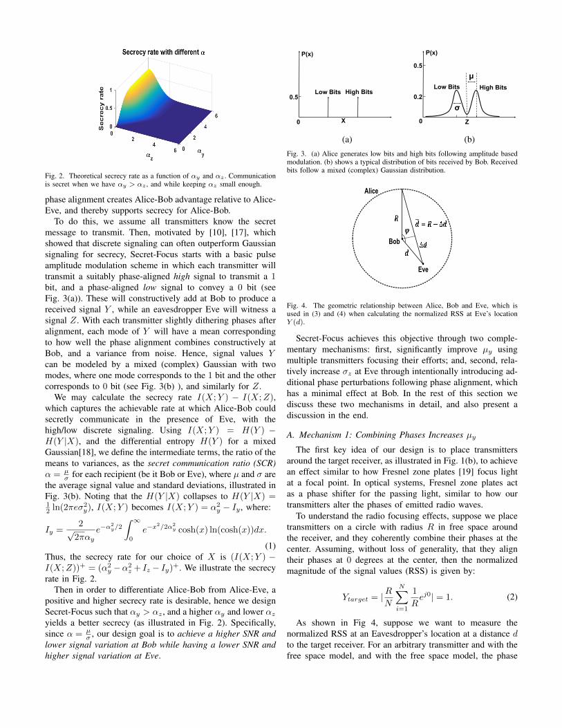
Fig. 2. Theoretical secrecy rate as a function of αy and αz . Communicationis secret when we have αy > αz , and while keeping αz small enough.
phase alignment creates Alice-Bob advantage relative to Alice-Eve, and thereby supports secrecy for Alice-Bob.
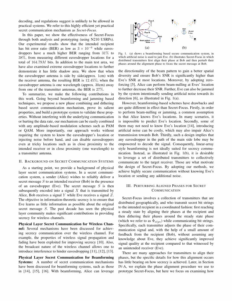
To do this, we assume all transmitters know the secretmessage to transmit. Then, motivated by [10], [17], whichshowed that discrete signaling can often outperform Gaussiansignaling for secrecy, Secret-Focus starts with a basic pulseamplitude modulation scheme in which each transmitter willtransmit a suitably phase-aligned high signal to transmit a 1bit, and a phase-aligned low signal to convey a 0 bit (seeFig. 3(a)). These will constructively add at Bob to produce areceived signal Y , while an eavesdropper Eve will witness asignal Z. With each transmitter slightly dithering phases afteralignment, each mode of Y will have a mean correspondingto how well the phase alignment combines constructively atBob, and a variance from noise. Hence, signal values Ycan be modeled by a mixed (complex) Gaussian with twomodes, where one mode corresponds to the 1 bit and the othercorresponds to 0 bit (see Fig. 3(b) ), and similarly for Z.
We may calculate the secrecy rate I(X;Y ) − I(X;Z),which captures the achievable rate at which Alice-Bob couldsecretly communicate in the presence of Eve, with thehigh/low discrete signaling. Using I(X;Y ) = H(Y ) −H(Y |X), and the differential entropy H(Y ) for a mixedGaussian[18], we define the intermediate terms, the ratio of themeans to variances, as the secret communication ratio (SCR)α = µ
σ for each recipient (be it Bob or Eve), where µ and σ arethe average signal value and standard deviations, illustrated inFig. 3(b). Noting that the H(Y |X) collapses to H(Y |X) =12 ln(2πeσ2
y), I(X;Y ) becomes I(X;Y ) = α2y − Iy , where:
Iy =2√
2παye−α
2y/2
∫ ∞0
e−x2/2α2
y cosh(x) ln(cosh(x))dx.
(1)Thus, the secrecy rate for our choice of X is (I(X;Y ) −I(X;Z))+ = (α2
y −α2z + Iz − Iy)+. We illustrate the secrecy
rate in Fig. 2.Then in order to differentiate Alice-Bob from Alice-Eve, a
positive and higher secrecy rate is desirable, hence we designSecret-Focus such that αy > αz , and a higher αy and lower αzyields a better secrecy (as illustrated in Fig. 2). Specifically,since α = µ
σ , our design goal is to achieve a higher SNR andlower signal variation at Bob while having a lower SNR andhigher signal variation at Eve.
0.5
P(x)
0 X
Low Bits High Bits0.2
P(x)
0 Z
0.5
Low Bits High Bits
(a) (b)Fig. 3. (a) Alice generates low bits and high bits following amplitude basedmodulation. (b) shows a typical distribution of bits received by Bob. Receivedbits follow a mixed (complex) Gaussian distribution.
Bob
Eve
Alice
Fig. 4. The geometric relationship between Alice, Bob and Eve, which isused in (3) and (4) when calculating the normalized RSS at Eve’s locationY (d).
Secret-Focus achieves this objective through two comple-mentary mechanisms: first, significantly improve µy usingmultiple transmitters focusing their efforts; and, second, rela-tively increase σz at Eve through intentionally introducing ad-ditional phase perturbations following phase alignment, whichhas a minimal effect at Bob. In the rest of this section wediscuss these two mechanisms in detail, and also present adiscussion in the end.
A. Mechanism 1: Combining Phases Increases µyThe first key idea of our design is to place transmitters
around the target receiver, as illustrated in Fig. 1(b), to achievean effect similar to how Fresnel zone plates [19] focus lightat a focal point. In optical systems, Fresnel zone plates actas a phase shifter for the passing light, similar to how ourtransmitters alter the phases of emitted radio waves.
To understand the radio focusing effects, suppose we placetransmitters on a circle with radius R in free space aroundthe receiver, and they coherently combine their phases at thecenter. Assuming, without loss of generality, that they aligntheir phases at 0 degrees at the center, then the normalizedmagnitude of the signal values (RSS) is given by:
Ytarget = |RN
N∑i=1
1
Rej0| = 1. (2)
As shown in Fig 4, suppose we want to measure thenormalized RSS at an Eavesdropper’s location at a distance dto the target receiver. For an arbitrary transmitter and with thefree space model, and with the free space model, the phase
(a) (b)
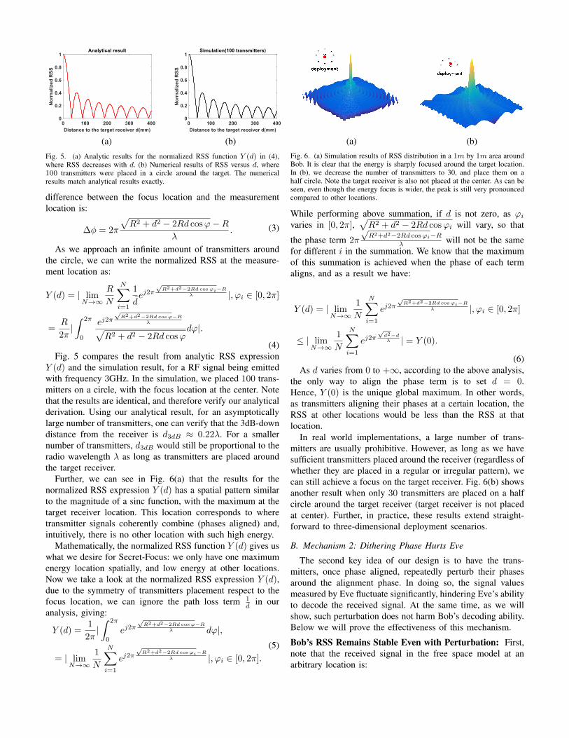
Fig. 5. (a) Analytic results for the normalized RSS function Y (d) in (4),where RSS decreases with d. (b) Numerical results of RSS versus d, where100 transmitters were placed in a circle around the target. The numericalresults match analytical results exactly.
difference between the focus location and the measurementlocation is:
∆φ = 2π
√R2 + d2 − 2Rd cosϕ−R
λ. (3)
As we approach an infinite amount of transmitters aroundthe circle, we can write the normalized RSS at the measure-ment location as:
Y (d) = | limN→∞
R
N
N∑i=1
1
dej2π
√R2+d2−2Rd cosϕi−R
λ |, ϕi ∈ [0, 2π]
=R
2π|∫ 2π
0
ej2π√R2+d2−2Rd cosϕ−R
λ√R2 + d2 − 2Rd cosϕ
dϕ|.
(4)Fig. 5 compares the result from analytic RSS expression
Y (d) and the simulation result, for a RF signal being emittedwith frequency 3GHz. In the simulation, we placed 100 trans-mitters on a circle, with the focus location at the center. Notethat the results are identical, and therefore verify our analyticalderivation. Using our analytical result, for an asymptoticallylarge number of transmitters, one can verify that the 3dB-downdistance from the receiver is d3dB ≈ 0.22λ. For a smallernumber of transmitters, d3dB would still be proportional to theradio wavelength λ as long as transmitters are placed aroundthe target receiver.
Further, we can see in Fig. 6(a) that the results for thenormalized RSS expression Y (d) has a spatial pattern similarto the magnitude of a sinc function, with the maximum at thetarget receiver location. This location corresponds to wheretransmitter signals coherently combine (phases aligned) and,intuitively, there is no other location with such high energy.
Mathematically, the normalized RSS function Y (d) gives uswhat we desire for Secret-Focus: we only have one maximumenergy location spatially, and low energy at other locations.Now we take a look at the normalized RSS expression Y (d),due to the symmetry of transmitters placement respect to thefocus location, we can ignore the path loss term 1
din our
analysis, giving:
Y (d) =1
2π|∫ 2π
0
ej2π√R2+d2−2Rd cosϕ−R
λ dϕ|,
= | limN→∞
1
N
N∑i=1
ej2π√R2+d2−2Rd cosϕi−R
λ |, ϕi ∈ [0, 2π].
(5)
deploymentdeployment
(a) (b)Fig. 6. (a) Simulation results of RSS distribution in a 1m by 1m area aroundBob. It is clear that the energy is sharply focused around the target location.In (b), we decrease the number of transmitters to 30, and place them on ahalf circle. Note the target receiver is also not placed at the center. As can beseen, even though the energy focus is wider, the peak is still very pronouncedcompared to other locations.
While performing above summation, if d is not zero, as ϕivaries in [0, 2π],
√R2 + d2 − 2Rd cosϕi will vary, so that
the phase term 2π
√R2+d2−2Rd cosϕi−R
λ will not be the samefor different i in the summation. We know that the maximumof this summation is achieved when the phase of each termaligns, and as a result we have:
Y (d) = | limN→∞
1
N
N∑i=1
ej2π√R2+d2−2Rd cosϕi−R
λ |, ϕi ∈ [0, 2π]
≤ | limN→∞
1
N
N∑i=1
ej2π√d2−dλ | = Y (0).
(6)As d varies from 0 to +∞, according to the above analysis,
the only way to align the phase term is to set d = 0.Hence, Y (0) is the unique global maximum. In other words,as transmitters aligning their phases at a certain location, theRSS at other locations would be less than the RSS at thatlocation.
In real world implementations, a large number of trans-mitters are usually prohibitive. However, as long as we havesufficient transmitters placed around the receiver (regardless ofwhether they are placed in a regular or irregular pattern), wecan still achieve a focus on the target receiver. Fig. 6(b) showsanother result when only 30 transmitters are placed on a halfcircle around the target receiver (target receiver is not placedat center). Further, in practice, these results extend straight-forward to three-dimensional deployment scenarios.
B. Mechanism 2: Dithering Phase Hurts Eve
The second key idea of our design is to have the trans-mitters, once phase aligned, repeatedly perturb their phasesaround the alignment phase. In doing so, the signal valuesmeasured by Eve fluctuate significantly, hindering Eve’s abilityto decode the received signal. At the same time, as we willshow, such perturbation does not harm Bob’s decoding ability.Below we will prove the effectiveness of this mechanism.
Bob’s RSS Remains Stable Even with Perturbation: First,note that the received signal in the free space model at anarbitrary location is:
~Y (φ1, φ2, ..., φN ) =
N∑i
Aiejφi . (7)
where Ai and φi denote the amplitude and phase of the ith
signal source received at the location, and N is the numberof signal sources (transmitters). Next, the real and imaginarypart of the received signal are:
~Yreal = A1 +A2 cos θ1 +A3 cos θ2 + ...+An cos θN−1,
~Yimg = A2 sin θ1 +A3 sin θ2 + ...+An sin θN−1.(8)
in which θi is the phase difference between signal i + 1and the first signal (i.e., with φ1 as the reference phase).Thus, the squared amplitude of the received signal isY 2(θ1, θ2, ..., θN−1) = ~Y 2
real + ~Y 2img . The derivative of Y 2
with respect to θi−1 is given by:
∂Y 2
∂θi−1= 2Ai+1(−A1 sin θi−1 +A2 sin(θ1 − θi−1)+
A3 sin(θ2 − θi−1) + ...+AN sin(θN−2 − θi−1)).
(9)
in which i ∈ [2, N ]. Considering θ1, θ2, ..., θN−1 are in-dependent, the impact of small phase perturbations uponY 2(θ1, θ2, ..., θN−1), is the sum of the partial derivatives:
G(θ1, θ2, ..., θN−1) =
N−1∑i
∂Y 2
∂θi,
= −2A1(A2 sin θ1 +A3 sin θ2 + ...+AN sin θN−1).
(10)
Here, θ1 = θ2 = ... = θN−1 ≈ 0 since the signal sourcesare properly phase aligned, giving G(θ1, θ2, ..., θN−1) ≈ 0at the target receiver. In particular, the target location hasthe lowest variability with respect to phases θ1, θ2, ..., θN−1
because the slope G = 0. Hence, we have shown that Bob’sRSS values will NOT fluctuate much due to small phaseperturbations we choose to introduce.
Eve’s RSS Becomes Unstable and Has Large Variation:Next, we examine the impact that small fluctuations aroundthe phase alignment optimum would have upon Eve. Assumea large number of transmitters on a circle N → ∞, and thetarget receiver at the center. Similar to Equation 4, we calculateG() at a distance d from Bob’s location, which we refer to asG(d). By taking the limit, we get the integral:
G(d) = −2
∫ 2π
0
sin (2π
√R2+d2−2Rd cosϕ−R
λ )
(R− d)√R2 + d2 − 2Rd cosϕ
dϕ.
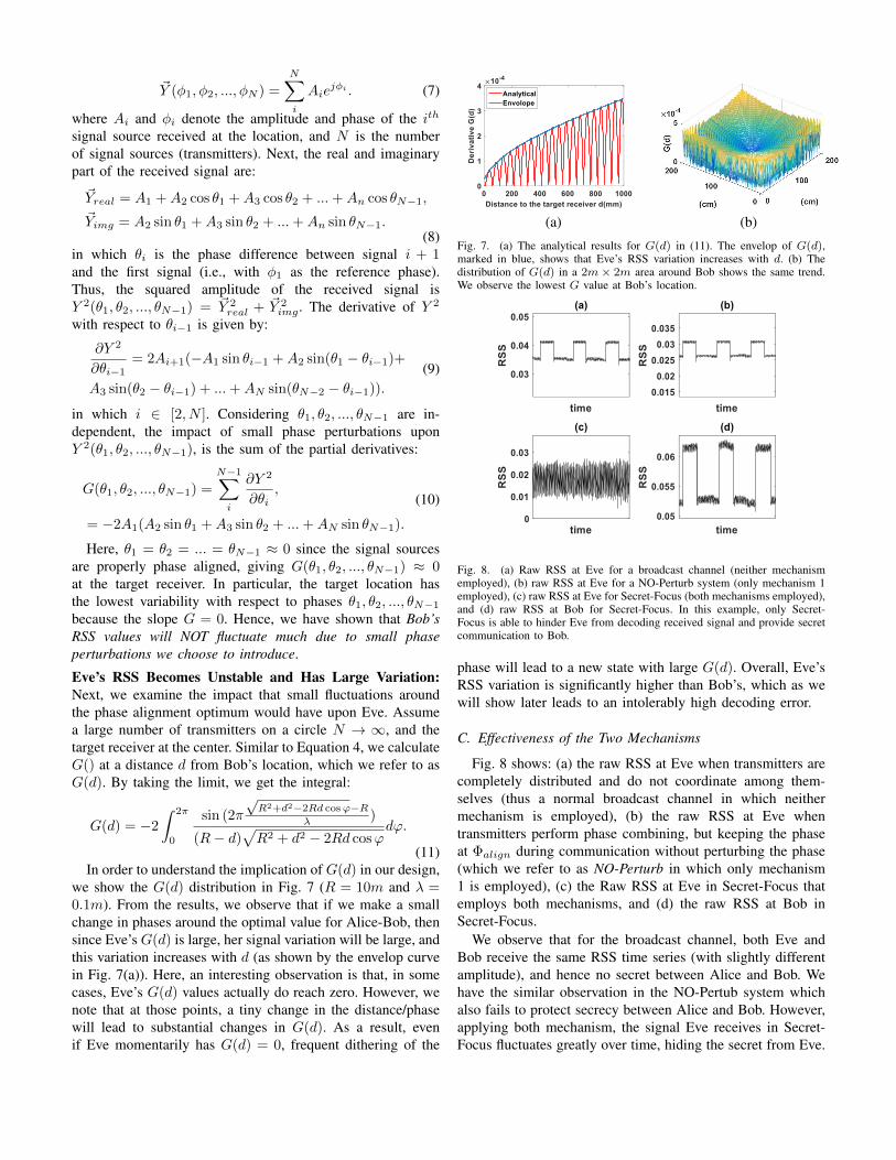
(11)In order to understand the implication of G(d) in our design,
we show the G(d) distribution in Fig. 7 (R = 10m and λ =0.1m). From the results, we observe that if we make a smallchange in phases around the optimal value for Alice-Bob, thensince Eve’s G(d) is large, her signal variation will be large, andthis variation increases with d (as shown by the envelop curvein Fig. 7(a)). Here, an interesting observation is that, in somecases, Eve’s G(d) values actually do reach zero. However, wenote that at those points, a tiny change in the distance/phasewill lead to substantial changes in G(d). As a result, evenif Eve momentarily has G(d) = 0, frequent dithering of the
(a) (b)
Fig. 7. (a) The analytical results for G(d) in (11). The envelop of G(d),marked in blue, shows that Eve’s RSS variation increases with d. (b) Thedistribution of G(d) in a 2m× 2m area around Bob shows the same trend.We observe the lowest G value at Bob’s location.
Fig. 8. (a) Raw RSS at Eve for a broadcast channel (neither mechanismemployed), (b) raw RSS at Eve for a NO-Perturb system (only mechanism 1employed), (c) raw RSS at Eve for Secret-Focus (both mechanisms employed),and (d) raw RSS at Bob for Secret-Focus. In this example, only Secret-Focus is able to hinder Eve from decoding received signal and provide secretcommunication to Bob.
phase will lead to a new state with large G(d). Overall, Eve’sRSS variation is significantly higher than Bob’s, which as wewill show later leads to an intolerably high decoding error.
C. Effectiveness of the Two Mechanisms
Fig. 8 shows: (a) the raw RSS at Eve when transmitters arecompletely distributed and do not coordinate among them-selves (thus a normal broadcast channel in which neithermechanism is employed), (b) the raw RSS at Eve whentransmitters perform phase combining, but keeping the phaseat Φalign during communication without perturbing the phase(which we refer to as NO-Perturb in which only mechanism1 is employed), (c) the Raw RSS at Eve in Secret-Focus thatemploys both mechanisms, and (d) the raw RSS at Bob inSecret-Focus.
We observe that for the broadcast channel, both Eve andBob receive the same RSS time series (with slightly differentamplitude), and hence no secret between Alice and Bob. Wehave the similar observation in the NO-Pertub system whichalso fails to protect secrecy between Alice and Bob. However,applying both mechanism, the signal Eve receives in Secret-Focus fluctuates greatly over time, hiding the secret from Eve.
Bob20M
20M
3M
Roof-mount GPS
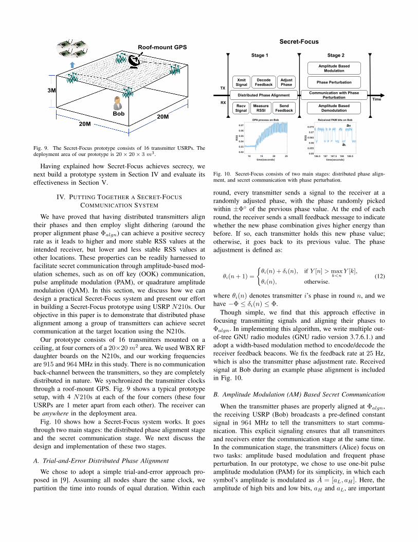
Fig. 9. The Secret-Focus prototype consists of 16 transmitter USRPs. Thedeployment area of our prototype is 20× 20× 3 m3.
Having explained how Secret-Focus achieves secrecy, wenext build a prototype system in Section IV and evaluate itseffectiveness in Section V.
IV. PUTTING TOGETHER A SECRET-FOCUSCOMMUNICATION SYSTEM
We have proved that having distributed transmitters aligntheir phases and then employ slight dithering (around theproper alignment phase Φalgn) can achieve a positive secrecyrate as it leads to higher and more stable RSS values at theintended receiver, but lower and less stable RSS values atother locations. These properties can be readily harnessed tofacilitate secret communication through amplitude-based mod-ulation schemes, such as on off key (OOK) communication,pulse amplitude modulation (PAM), or quadrature amplitudemodulation (QAM). In this section, we discuss how we candesign a practical Secret-Focus system and present our effortin building a Secret-Focus prototype using USRP N210s. Ourobjective in this paper is to demonstrate that distributed phasealignment among a group of transmitters can achieve secretcommunication at the target location using the N210s.
Our prototype consists of 16 transmitters mounted on aceiling, at four corners of a 20×20 m2 area. We used WBX RFdaughter boards on the N210s, and our working frequenciesare 915 and 964 MHz in this study. There is no communicationback-channel between the transmitters, so they are completelydistributed in nature. We synchronized the transmitter clocksthrough a roof-mount GPS. Fig. 9 shows a typical prototypesetup, with 4 N210s at each of the four corners (these fourUSRPs are 1 meter apart from each other). The receiver canbe anywhere in the deployment area.
Fig. 10 shows how a Secret-Focus system works. It goesthrough two main stages: the distributed phase alignment stageand the secret communication stage. We next discuss thedesign and implementation of these two stages.
A. Trial-and-Error Distributed Phase Alignment
We chose to adopt a simple trial-and-error approach pro-posed in [9]. Assuming all nodes share the same clock, wepartition the time into rounds of equal duration. Within each
Distributed Phase AlignmentTime
TX
Xmit
Signal
Decode
Feedback
Adjust
Phase
RXMeasure
RSSI
Send
Feedback
Communication with Phase
Perturbation
Amplitude Based
Demodulation
Secret-Focus
Recv
Signal
Phase Perturbation
Amplitude Based
Modulation
aH
aL
Stage 1 Stage 2
Fig. 10. Secret-Focus consists of two main stages: distributed phase align-ment, and secret communication with phase perturbation.
round, every transmitter sends a signal to the receiver at arandomly adjusted phase, with the phase randomly pickedwithin ±Φ◦ of the previous phase value. At the end of eachround, the receiver sends a small feedback message to indicatewhether the new phase combination gives higher energy thanbefore. If so, each transmitter holds this new phase value;otherwise, it goes back to its previous value. The phaseadjustment is defined as:
θi(n+ 1) =
{θi(n) + δi(n), if Y [n] > max
k<nY [k],
θi(n), otherwise.(12)
where θi(n) denotes transmitter i’s phase in round n, and wehave −Φ ≤ δi(n) ≤ Φ.
Though simple, we find that this approach effective infocusing transmitting signals and aligning their phases toΦalgn. In implementing this algorithm, we write multiple out-of-tree GNU radio modules (GNU radio version 3.7.6.1.) andadopt a width-based modulation method to encode/decode thereceiver feedback beacons. We fix the feedback rate at 25 Hz,which is also the transmitter phase adjustment rate. Receivedsignal at Bob during an example phase alignment is includedin Fig. 10.
B. Amplitude Modulation (AM) Based Secret Communication
When the transmitter phases are properly aligned at Φalgn,the receiving USRP (Bob) broadcasts a pre-defined constantsignal in 964 MHz to tell the transmitters to start commu-nication. This explicit signaling ensures that all transmittersand receivers enter the communication stage at the same time.In the communication stage, the transmitters (Alice) focus ontwo tasks: amplitude based modulation and frequent phaseperturbation. In our prototype, we chose to use one-bit pulseamplitude modulation (PAM) for its simplicity, in which eachsymbol’s amplitude is modulated as A = [aL, aH ]. Here, theamplitude of high bits and low bits, aH and aL, are important
0.7 0.8 0.9 1 1.1
Normalized RSS
0
500
sy
mb
ols
(a)
0 0.2 0.4 0.6 0.8 1
Normalized RSS
0
500
sy
mb
ols
(b)
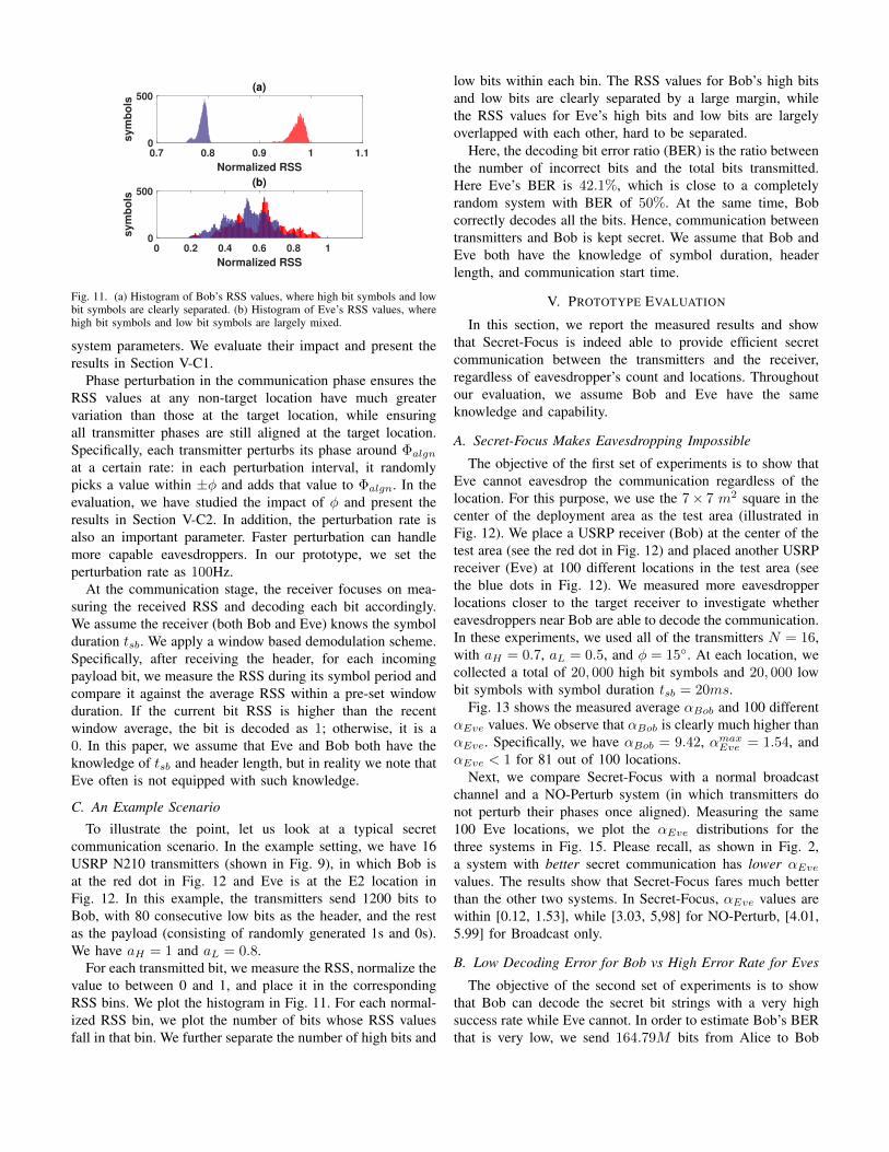
Fig. 11. (a) Histogram of Bob’s RSS values, where high bit symbols and lowbit symbols are clearly separated. (b) Histogram of Eve’s RSS values, wherehigh bit symbols and low bit symbols are largely mixed.
system parameters. We evaluate their impact and present theresults in Section V-C1.
Phase perturbation in the communication phase ensures theRSS values at any non-target location have much greatervariation than those at the target location, while ensuringall transmitter phases are still aligned at the target location.Specifically, each transmitter perturbs its phase around Φalgnat a certain rate: in each perturbation interval, it randomlypicks a value within ±φ and adds that value to Φalgn. In theevaluation, we have studied the impact of φ and present theresults in Section V-C2. In addition, the perturbation rate isalso an important parameter. Faster perturbation can handlemore capable eavesdroppers. In our prototype, we set theperturbation rate as 100Hz.
At the communication stage, the receiver focuses on mea-suring the received RSS and decoding each bit accordingly.We assume the receiver (both Bob and Eve) knows the symbolduration tsb. We apply a window based demodulation scheme.Specifically, after receiving the header, for each incomingpayload bit, we measure the RSS during its symbol period andcompare it against the average RSS within a pre-set windowduration. If the current bit RSS is higher than the recentwindow average, the bit is decoded as 1; otherwise, it is a0. In this paper, we assume that Eve and Bob both have theknowledge of tsb and header length, but in reality we note thatEve often is not equipped with such knowledge.
C. An Example Scenario
To illustrate the point, let us look at a typical secretcommunication scenario. In the example setting, we have 16USRP N210 transmitters (shown in Fig. 9), in which Bob isat the red dot in Fig. 12 and Eve is at the E2 location inFig. 12. In this example, the transmitters send 1200 bits toBob, with 80 consecutive low bits as the header, and the restas the payload (consisting of randomly generated 1s and 0s).We have aH = 1 and aL = 0.8.
For each transmitted bit, we measure the RSS, normalize thevalue to between 0 and 1, and place it in the correspondingRSS bins. We plot the histogram in Fig. 11. For each normal-ized RSS bin, we plot the number of bits whose RSS valuesfall in that bin. We further separate the number of high bits and
low bits within each bin. The RSS values for Bob’s high bitsand low bits are clearly separated by a large margin, whilethe RSS values for Eve’s high bits and low bits are largelyoverlapped with each other, hard to be separated.
Here, the decoding bit error ratio (BER) is the ratio betweenthe number of incorrect bits and the total bits transmitted.Here Eve’s BER is 42.1%, which is close to a completelyrandom system with BER of 50%. At the same time, Bobcorrectly decodes all the bits. Hence, communication betweentransmitters and Bob is kept secret. We assume that Bob andEve both have the knowledge of symbol duration, headerlength, and communication start time.
V. PROTOTYPE EVALUATION
In this section, we report the measured results and showthat Secret-Focus is indeed able to provide efficient secretcommunication between the transmitters and the receiver,regardless of eavesdropper’s count and locations. Throughoutour evaluation, we assume Bob and Eve have the sameknowledge and capability.
A. Secret-Focus Makes Eavesdropping Impossible
The objective of the first set of experiments is to show thatEve cannot eavesdrop the communication regardless of thelocation. For this purpose, we use the 7× 7 m2 square in thecenter of the deployment area as the test area (illustrated inFig. 12). We place a USRP receiver (Bob) at the center of thetest area (see the red dot in Fig. 12) and placed another USRPreceiver (Eve) at 100 different locations in the test area (seethe blue dots in Fig. 12). We measured more eavesdropperlocations closer to the target receiver to investigate whethereavesdroppers near Bob are able to decode the communication.In these experiments, we used all of the transmitters N = 16,with aH = 0.7, aL = 0.5, and φ = 15◦. At each location, wecollected a total of 20, 000 high bit symbols and 20, 000 lowbit symbols with symbol duration tsb = 20ms.
Fig. 13 shows the measured average αBob and 100 differentαEve values. We observe that αBob is clearly much higher thanαEve. Specifically, we have αBob = 9.42, αmaxEve = 1.54, andαEve < 1 for 81 out of 100 locations.
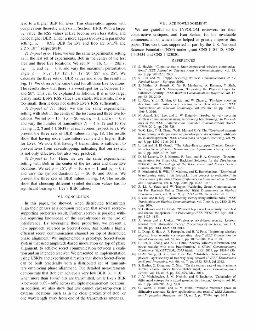
Next, we compare Secret-Focus with a normal broadcastchannel and a NO-Perturb system (in which transmitters donot perturb their phases once aligned). Measuring the same100 Eve locations, we plot the αEve distributions for thethree systems in Fig. 15. Please recall, as shown in Fig. 2,a system with better secret communication has lower αEvevalues. The results show that Secret-Focus fares much betterthan the other two systems. In Secret-Focus, αEve values arewithin [0.12, 1.53], while [3.03, 5,98] for NO-Perturb, [4.01,5.99] for Broadcast only.
B. Low Decoding Error for Bob vs High Error Rate for Eves
The objective of the second set of experiments is to showthat Bob can decode the secret bit strings with a very highsuccess rate while Eve cannot. In order to estimate Bob’s BERthat is very low, we send 164.79M bits from Alice to Bob
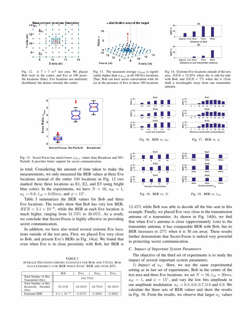
Fig. 12. A 7 × 7 m2 test area. We placedBob (red) in the center, and Eve at 100 possi-ble locations (blue). Eve locations not uniformlydistributed, but denser towards the center.
Fig. 13. The measured average αBob is signifi-cantly higher than αEve at all 100 Eve locations.Thus, Bob can have secret conversation with Al-ice in the presence of Eve at these 100 locations.
Fig. 14. Extreme Eve locations outside of the testarea. BER = 12.45% when she is side-by-sidewith Bob, and BER = 7% when she is 15cm(half a wavelength) away from one transmitterantenna.
Fig. 15. Secret-Focus has much lower αEve values than Broadcast and NO-Perturb. It provides better support for secret communication.
in total. Considering the amount of time taken to make themeasurements, we only measured the BER values at three Evelocations instead of the entire 100 locations in Fig. 12 (wemarked these three locations as E1, E2, and E3 using brightblue color). In the experiments, we have N = 16, aH = 1,aL = 0.8, tsb = 0.05ms, and φ = 15◦.
Table I summarizes the BER values for Bob and threeEve locations. The results show that Bob has very low BER,BER = 3.1 × 10⁻⁶, while the BER at each Eve location ismuch higher, ranging from 31.73% to 38.05%. As a result,we conclude that Secret-Focus is highly effective in providingsecret communication.
In addition, we have also tested several extreme Eve loca-tions outside of the test area. First, we placed Eve very closeto Bob, and present Eve’s BERs in Fig. 14(a). We found thateven when Eve is in close proximity with Bob, her BER is
TABLE IAVERAGE DECODING ERRORS STATISTICS FOR BOB AND 3 EVES. BOB
HAS EXTREMELY LOW BER WHILE EVES’ BER ARE OVER 30%.
Bob Eve1 Eve2 Eve3Total Number of BitsTransmitted (bits)
164.79M
Total Number of BitsIncorrectly Decoded(bits)
52.31K 52.29M 62.70M 60.36M
Estimated BER 3.1× 10⁻⁶ 0.3173 0.3805 0.3663
Fig. 16. BER vs. aL. Fig. 17. BER vs. φ.
Fig. 18. BER vs. N .
20ms 40ms 100ms0
20
40
BE
R %
Eve1
20ms 40ms 100ms0
20
40
BE
R %
Eve2
20ms 40ms 100ms
Symbol duration tsb
0
20
40
BE
R %
Eve3
Fig. 19. BER vs. tsb.
12.45% while Bob was able to decode all the bits sent in thisexample. Finally, we placed Eve very close to the transmissionantenna of a transmitter. As shown in Fig. 14(b), we findthat when Eve’s antenna is close (approximately 1cm) to thetransmitter antenna, it has comparable BER with Bob, but itsBER increases to 27% when it is 30 cm away. These resultsfurther demonstrate that Secret-Focus is indeed very powerfulin protecting secret communication.
C. Impact of Important System Parameters
The objective of the third set of experiments is to study theimpact of several important system parameters.
1) Impact of aL: Here, we use the same experimentalsetting as in last set of experiments, Bob in the center of thetest area and three Eve locations. we set N = 16, tsb = 20ms,aH = 1, and φ = 15◦, and vary the low bits amplitude inour amplitude modulation: aL = 0.5, 0.6, 0.7, 0.8 and 0.9. Wecalculate the three sets of BER values and show the resultsin Fig. 16. From the results, we observe that larger aL values
lead to a higher BER for Eves. This observation agrees withour previous theoretic analysis in Section III-B. With a largeraL value, the RSS values at Eve become even less stable, andhence higher BER. Under a more aggressive system parametersetting, aL = 0.95, BER for Eve and Bob are 57.1% and2.2× 10−6 respectively.
2) Impact of φ: Here, we use the same experimental settingas in the last set of experiments, Bob in the center of the testarea and three Eve locations. We set N = 16, tsb = 20ms,aH = 1, and aL = 0.8, and vary the maximum perturbationangle φ = 5◦, 7◦, 10◦, 12◦, 15◦, 17◦, 20◦, 22◦ and 25◦. Wecalculate the three sets of BER values and show the results inFig. 17. We observe the same trend for all three Eve locations.The results show that there is a sweet spot for φ, between 15◦
and 20◦. This can be explained as follows. If φ is too large,it may make Bob’s RSS values less stable. Meanwhile, if φ istoo small, then it does not disturb Eve’s RSS sufficiently.
3) Impact of N : Here, we use the same experimentalsetting with Bob in the center of the test area and three Eve lo-cations. We set φ = 15◦, tsb = 20ms, aH = 1, and aL = 0.8,and vary the number of transmitters N = 4, 8, 12 and 16 (byhaving 1, 2, 3 and 4 USRP(s) at each corner, respectively). Wepresent the three sets of BER values in Fig. 18. The resultsshow that having more transmitters can yield a higher BERfor Eves. We note that having 4 transmitters is sufficient toprevent Eves from eavesdropping, indicating that our systemis not only effective, but also very practical.
4) Impact of tsb: Here, we use the same experimentalsetting with Bob in the center of the test area and three Evelocations. We set φ = 15◦, N = 16, aH = 1, and aL = 0.7,and vary the symbol duration tsb = 20, 40 and 100ms. Wepresent the three sets of BER values in Fig. 19. The resultsshow that choosing different symbol duration values has nosignificant bearing on Eve’s BER values.
VI. CONCLUSION
In this paper, we showed, when distributed transmittersalign their phases at a common receiver, that several secrecy-supporting properties result. Further, secrecy is possible with-out requiring knowledge of the eavesdropper or the use ofinterference. By leveraging these properties, we present anew approach, referred as Secret-Focus, that builds a highlyefficient secret communication channel on top of distributedphase alignment. We implemented a prototype Secret-Focussystem that used amplitude-based modulation on top of phasealignment, to achieve secret communication between a coali-tion and an intended receiver. We presented an implementationusing USRPs and experimental results that shows Secret-Focuscan be built practically with a distributed set of transmit-ters employing phase alignment. Our detailed measurementsdemonstrate that Bob can achieve a very low BER, 3.1×10⁻⁶
when more than 160M bits are transmitted, while Eve’s BERis between 30%−60% across multiple measurement locations.In addition, we also show that Eve cannot eavesdrop even atextreme locations, such as in the close proximity of Bob, orone wavelength away from one of the transmitters antennas.
VII. ACKNOWLEDGEMENT
We are grateful to the INFOCOM reviewers for theirconstructive critiques, and Ivan Seskar, for his invaluablecomments, all of which have helped us greatly improve thispaper. This work was supported in part by the U.S. NationalScience Foundation(NSF) under grant CNS-1404118, CNS-1443434 and CNS-1423020.
REFERENCES
[1] S. Haykin, “Cognitive radio: Brain-empowered wireless communica-tions,” IEEE Journal on Selected Areas in Communications, vol. 23,no. 2, pp. 201–220, 2005.
[2] R. Liu and W. Trappe, Securing Wireless Communications at thePhysical Layer. Springer, 2010.
[3] S. Mathur, A. Reznik, C. Ye, R. Mukherjee, A. Rahman, Y. Shah,W. Trappe, and N. Mandayam, “Exploiting the Physical Layer forEnhanced Security,” IEEE Wireless Communications Magazine, vol. 17,pp. 63–70, 2010.
[4] L. Xiao, Y. Li, G. Han, G. Liu, and W. Zhuang, “Phy-layer spoofingdetection with reinforcement learning in wireless networks,” IEEETransactions on Vehicular Technology, vol. 65, no. 12, pp. 10 037–10 047, 2016.
[5] N. Anand, S.-J. Lee, and E. W. Knightly, “Strobe: Actively securingwireless communications using zero-forcing beamforming,” in Proceed-ings of the IEEE Conference on Computer Communications (INFO-COM), 2012, pp. 720–728.
[6] W.-C. Liao, T.-H. Chang, W.-K. Ma, and C.-Y. Chi, “Qos-based transmitbeamforming in the presence of eavesdroppers: An optimized artificial-noise-aided approach,” IEEE Transactions on Signal Processing, vol. 59,no. 3, pp. 1202–1216, 2011.
[7] L. Lai and H. El Gamal, “The Relay–Eavesdropper Channel: Cooper-ation for Secrecy,” IEEE Transactions on Information Theory, vol. 54,no. 9, pp. 4005–4019, 2008.
[8] D. M. Laverty, D. J. Morrow, R. Best, and P. A. Crossley, “Telecom-munications for Smart Grid: Backhaul Solutions for the DistributionNetwork,” in Proceedings of the IEEE Power and Energy SocietyGeneral Meeting, 2010, pp. 1–6.
[9] R. Mudumbai, B. Wild, U. Madhow, and K. Ramchandran, “Distributedbeamforming using 1 bit feedback: from concept to realization,” inProceedings of the 44th Allerton Conference on Communication, Controland Computation, vol. 8, Sep. 2006, pp. 1020–1027.
[10] Z. Li, R. Yates, and W. Trappe, “Achieving Secret Communicationfor Fast Rayleigh Fading Channels,” IEEE Transactions on WirelessCommunications, vol. 9, no. 9, pp. 2792 –2799, September 2010.
[11] S. Goel and R. Negi, “Guaranteeing secrecy using artificial noise,” IEEETransactions on Wireless Communications, vol. 7, no. 6, pp. 2180–2189,June 2008.
[12] S. Gollakota and D. Katabi, “Physical layer wireless security made fastand channel independent,” in Proceedings IEEE INFOCOM, April 2011,pp. 1125–1133.
[13] A. Yener and S. Ulukus, “Wireless physical-layer security: Lessonslearned from information theory,” Proceedings of the IEEE, vol. 103,no. 10, pp. 1814–1825, Oct 2015.
[14] L. Dong, Z. Han, A. P. Petropulu, and H. V. Poor, “Improving wirelessphysical layer security via cooperating relays,” IEEE Transactions onSignal Processing, vol. 58, no. 3, pp. 1875–1888, Mar. 2010.
[15] L. Liu, R. Zhang, and K.-C. Chua, “Secrecy wireless information andpower transfer with miso beamforming,” in Global CommunicationsConference (GLOBECOM), 2013 IEEE. IEEE, 2013, pp. 1831–1836.
[16] H.-M. Wang, Q. Yin, and X.-G. Xia, “Distributed beamforming forphysical-layer security of two-way relay networks,” IEEE Transactionson Signal Processing, vol. 60, no. 7, pp. 3532–3545, Jul 2012.
[17] S. Bashar, Z. Ding, and C. Xiao, “On the secrecy rate of multi-antennawiretap channel under finite-alphabet input,” IEEE CommunicationsLetters, vol. 15, no. 5, pp. 527–529, May 2011.
[18] J. V. Michalowicz, J. M. Nichols, and F. Bucholtz, “Calculation ofdifferential entropy for a mixed gaussian distribution,” Entropy, vol. 10,no. 3, pp. 200–206, Aug 2008.
[19] G. Webb, I. Minin, and O. V. Minin, “Variable reference phase indiffractive antennas: Review, applications, new results,” IEEE Antennasand Propagation Magazine, vol. 53, no. 2, pp. 77–94, Apr. 2011.


![MPSS: Mobile Proactive Secret Sharingpmg.lcs.mit.edu/papers/a34-schultz.pdf · secret sharing was first proposed by Ostrovsky and Yung [1991] and shown to be practical in a synchronous](https://img.pdfslide.us/doc/110x75/5f9d218160f84d36d96b3cb0/mpss-mobile-proactive-secret-secret-sharing-was-irst-proposed-by-ostrovsky-and.jpg)


![Paper and Thin Layer Chromatography (TLC) Experiment 4 BCH 333[practical]](https://img.pdfslide.us/doc/110x75/56649dca5503460f94ac0512/paper-and-thin-layer-chromatography-tlc-experiment-4-bch-333practical.jpg)


![Marketo's Secret Sauce for Revenue - a Practical Case Study [#DemandCon]](https://img.pdfslide.us/doc/110x75/55d53e96bb61eb2a678b476d/marketos-secret-sauce-for-revenue-a-practical-case-study-demandcon.jpg)


![Paper and Thin Layer Chromatography (TLC) Experiment 6 BCH 333 [practical]](https://img.pdfslide.us/doc/110x75/56649f345503460f94c515db/paper-and-thin-layer-chromatography-tlc-experiment-6-bch-333-practical.jpg)