Embed Size (px)
Citation preview
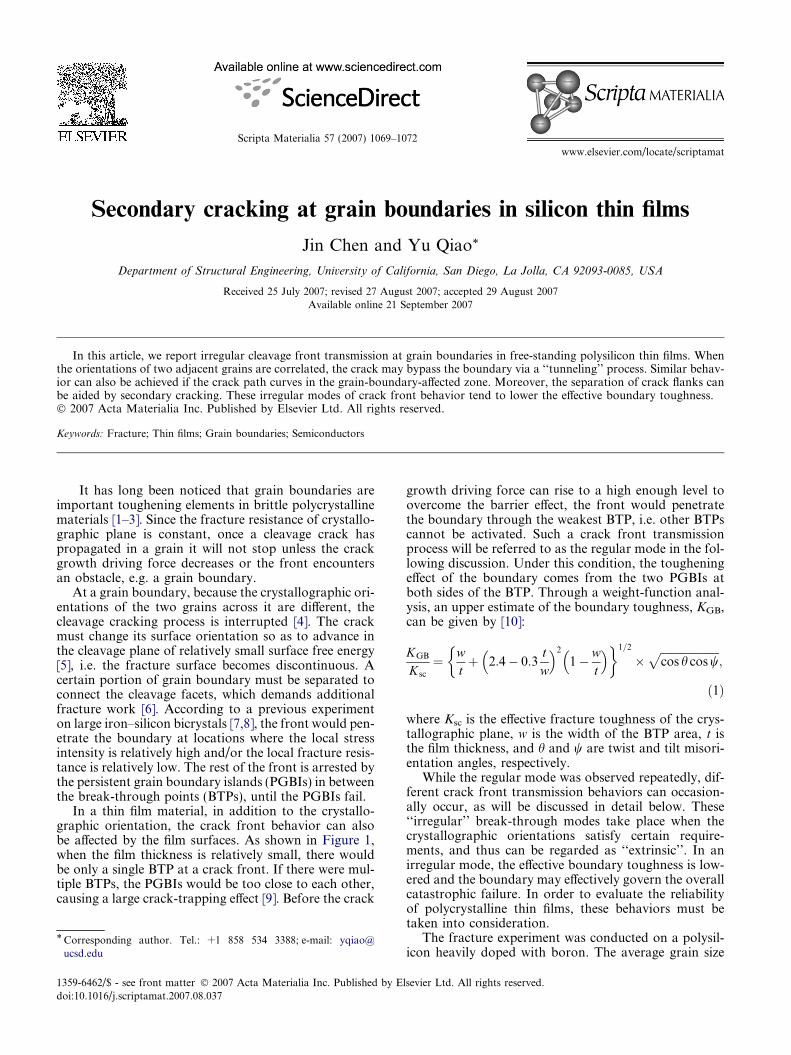
Scripta Materialia 57 (2007) 1069–1072
www.elsevier.com/locate/scriptamat
Secondary cracking at grain boundaries in silicon thin films
Jin Chen and Yu Qiao*
Department of Structural Engineering, University of California, San Diego, La Jolla, CA 92093-0085, USA
Received 25 July 2007; revised 27 August 2007; accepted 29 August 2007Available online 21 September 2007
In this article, we report irregular cleavage front transmission at grain boundaries in free-standing polysilicon thin films. Whenthe orientations of two adjacent grains are correlated, the crack may bypass the boundary via a ‘‘tunneling’’ process. Similar behav-ior can also be achieved if the crack path curves in the grain-boundary-affected zone. Moreover, the separation of crack flanks canbe aided by secondary cracking. These irregular modes of crack front behavior tend to lower the effective boundary toughness.� 2007 Acta Materialia Inc. Published by Elsevier Ltd. All rights reserved.
Keywords: Fracture; Thin films; Grain boundaries; Semiconductors
It has long been noticed that grain boundaries areimportant toughening elements in brittle polycrystallinematerials [1–3]. Since the fracture resistance of crystallo-graphic plane is constant, once a cleavage crack haspropagated in a grain it will not stop unless the crackgrowth driving force decreases or the front encountersan obstacle, e.g. a grain boundary.
At a grain boundary, because the crystallographic ori-entations of the two grains across it are different, thecleavage cracking process is interrupted [4]. The crackmust change its surface orientation so as to advance inthe cleavage plane of relatively small surface free energy[5], i.e. the fracture surface becomes discontinuous. Acertain portion of grain boundary must be separated toconnect the cleavage facets, which demands additionalfracture work [6]. According to a previous experimenton large iron–silicon bicrystals [7,8], the front would pen-etrate the boundary at locations where the local stressintensity is relatively high and/or the local fracture resis-tance is relatively low. The rest of the front is arrested bythe persistent grain boundary islands (PGBIs) in betweenthe break-through points (BTPs), until the PGBIs fail.
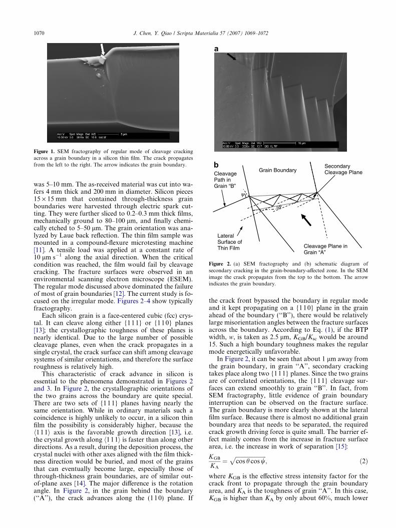
In a thin film material, in addition to the crystallo-graphic orientation, the crack front behavior can alsobe affected by the film surfaces. As shown in Figure 1,when the film thickness is relatively small, there wouldbe only a single BTP at a crack front. If there were mul-tiple BTPs, the PGBIs would be too close to each other,causing a large crack-trapping effect [9]. Before the crack
1359-6462/$ - see front matter � 2007 Acta Materialia Inc. Published by Eldoi:10.1016/j.scriptamat.2007.08.037
* Corresponding author. Tel.: +1 858 534 3388; e-mail: [email protected]
growth driving force can rise to a high enough level toovercome the barrier effect, the front would penetratethe boundary through the weakest BTP, i.e. other BTPscannot be activated. Such a crack front transmissionprocess will be referred to as the regular mode in the fol-lowing discussion. Under this condition, the tougheningeffect of the boundary comes from the two PGBIs atboth sides of the BTP. Through a weight-function anal-ysis, an upper estimate of the boundary toughness, KGB,can be given by [10]:
KGB
Ksc
¼ wtþ 2:4� 0:3
tw
� �2
1�wt
� �� �1=2
�ffiffiffiffiffiffiffiffiffiffiffiffiffiffiffiffiffiffiffiffifficos h cos w
p;
ð1Þ
where Ksc is the effective fracture toughness of the crys-tallographic plane, w is the width of the BTP area, t isthe film thickness, and h and w are twist and tilt misori-entation angles, respectively.
While the regular mode was observed repeatedly, dif-ferent crack front transmission behaviors can occasion-ally occur, as will be discussed in detail below. These‘‘irregular’’ break-through modes take place when thecrystallographic orientations satisfy certain require-ments, and thus can be regarded as ‘‘extrinsic’’. In anirregular mode, the effective boundary toughness is low-ered and the boundary may effectively govern the overallcatastrophic failure. In order to evaluate the reliabilityof polycrystalline thin films, these behaviors must betaken into consideration.
The fracture experiment was conducted on a polysil-icon heavily doped with boron. The average grain size
sevier Ltd. All rights reserved.
Cleavage Plane in Grain “A”
Grain Boundary SecondaryCleavage Plane Cleavage
Path inGrain “B”
θ
ψ
LateralSurface of Thin Film
a
b
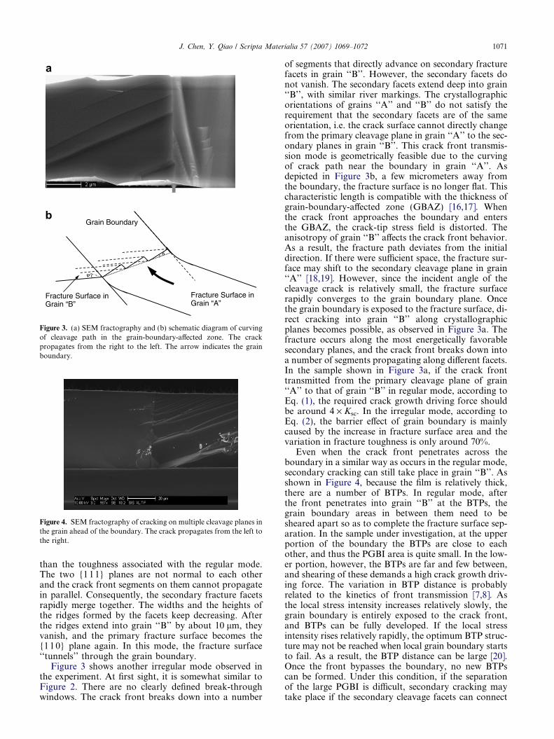
Figure 2. (a) SEM fractography and (b) schematic diagram ofsecondary cracking in the grain-boundary-affected zone. In the SEMimage the crack propagates from the top to the bottom. The arrowindicates the grain boundary.
Figure 1. SEM fractography of regular mode of cleavage crackingacross a grain boundary in a silicon thin film. The crack propagatesfrom the left to the right. The arrow indicates the grain boundary.
1070 J. Chen, Y. Qiao / Scripta Materialia 57 (2007) 1069–1072
was 5–10 mm. The as-received material was cut into wa-fers 4 mm thick and 200 mm in diameter. Silicon pieces15 · 15 mm that contained through-thickness grainboundaries were harvested through electric spark cut-ting. They were further sliced to 0.2–0.3 mm thick films,mechanically ground to 80–100 lm, and finally chemi-cally etched to 5–50 lm. The grain orientation was ana-lyzed by Laue back reflection. The thin film sample wasmounted in a compound-flexure microtesting machine[11]. A tensile load was applied at a constant rate of10 lm s�1 along the axial direction. When the criticalcondition was reached, the film would fail by cleavagecracking. The fracture surfaces were observed in anenvironmental scanning electron microscope (ESEM).The regular mode discussed above dominated the failureof most of grain boundaries [12]. The current study is fo-cused on the irregular mode. Figures 2–4 show typicallyfractography.
Each silicon grain is a face-centered cubic (fcc) crys-tal. It can cleave along either {11 1} or {110} planes[13]; the crystallographic toughness of these planes isnearly identical. Due to the large number of possiblecleavage planes, even when the crack propagates in asingle crystal, the crack surface can shift among cleavagesystems of similar orientations, and therefore the surfaceroughness is relatively high.
This characteristic of crack advance in silicon isessential to the phenomena demonstrated in Figures 2and 3. In Figure 2, the crystallographic orientations ofthe two grains across the boundary are quite special.There are two sets of {11 1} planes having nearly thesame orientation. While in ordinary materials such acoincidence is highly unlikely to occur, in a silicon thinfilm the possibility is considerably higher, because theh111i axis is the favorable growth direction [13], i.e.the crystal growth along h111i is faster than along otherdirections. As a result, during the deposition process, thecrystal nuclei with other axes aligned with the film thick-ness direction would be buried, and most of the grainsthat can eventually become large, especially those ofthrough-thickness grain boundaries, are of similar out-of-plane axes [14]. The major difference is the rotationangle. In Figure 2, in the grain behind the boundary(‘‘A’’), the crack advances along the (110) plane. If
the crack front bypassed the boundary in regular modeand it kept propagating on a {110} plane in the grainahead of the boundary (‘‘B’’), there would be relativelylarge misorientation angles between the fracture surfacesacross the boundary. According to Eq. (1), if the BTPwidth, w, is taken as 2.5 lm, KGB/Ksc would be around15. Such a high boundary toughness makes the regularmode energetically unfavorable.
In Figure 2, it can be seen that about 1 lm away fromthe grain boundary, in grain ‘‘A’’, secondary crackingtakes place along two {111} planes. Since the two grainsare of correlated orientations, the {111} cleavage sur-faces can extend smoothly to grain ‘‘B’’. In fact, fromSEM fractography, little evidence of grain boundaryinterruption can be observed on the fracture surface.The grain boundary is more clearly shown at the lateralfilm surface. Because there is almost no additional grainboundary area that needs to be separated, the requiredcrack growth driving force is quite small. The barrier ef-fect mainly comes from the increase in fracture surfacearea, i.e. the increase in work of separation [15]:
KGB
KA
¼ffiffiffiffiffiffiffiffiffiffiffiffiffiffiffiffiffiffiffiffiffifficos h cos w
p; ð2Þ
where KGB is the effective stress intensity factor for thecrack front to propagate through the grain boundaryarea, and KA is the toughness of grain ‘‘A’’. In this case,KGB is higher than KA by only about 60%, much lower
ψ
θ
Fracture Surface in Grain “A”
Grain Boundary
Fracture Surface in Grain “B”
a
b
Figure 3. (a) SEM fractography and (b) schematic diagram of curvingof cleavage path in the grain-boundary-affected zone. The crackpropagates from the right to the left. The arrow indicates the grainboundary.
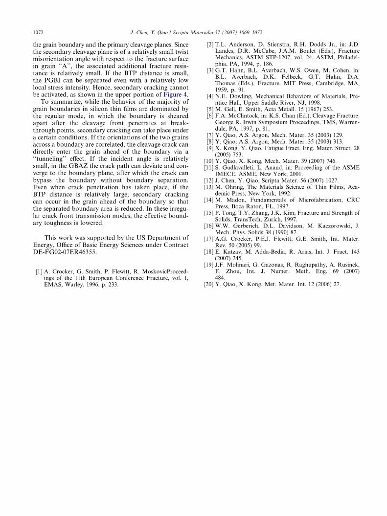
Figure 4. SEM fractography of cracking on multiple cleavage planes inthe grain ahead of the boundary. The crack propagates from the left tothe right.
J. Chen, Y. Qiao / Scripta Materialia 57 (2007) 1069–1072 1071
than the toughness associated with the regular mode.The two {111} planes are not normal to each otherand the crack front segments on them cannot propagatein parallel. Consequently, the secondary fracture facetsrapidly merge together. The widths and the heights ofthe ridges formed by the facets keep decreasing. Afterthe ridges extend into grain ‘‘B’’ by about 10 lm, theyvanish, and the primary fracture surface becomes the{11 0} plane again. In this mode, the fracture surface‘‘tunnels’’ through the grain boundary.
Figure 3 shows another irregular mode observed inthe experiment. At first sight, it is somewhat similar toFigure 2. There are no clearly defined break-throughwindows. The crack front breaks down into a number
of segments that directly advance on secondary fracturefacets in grain ‘‘B’’. However, the secondary facets donot vanish. The secondary facets extend deep into grain‘‘B’’, with similar river markings. The crystallographicorientations of grains ‘‘A’’ and ‘‘B’’ do not satisfy therequirement that the secondary facets are of the sameorientation, i.e. the crack surface cannot directly changefrom the primary cleavage plane in grain ‘‘A’’ to the sec-ondary planes in grain ‘‘B’’. This crack front transmis-sion mode is geometrically feasible due to the curvingof crack path near the boundary in grain ‘‘A’’. Asdepicted in Figure 3b, a few micrometers away fromthe boundary, the fracture surface is no longer flat. Thischaracteristic length is compatible with the thickness ofgrain-boundary-affected zone (GBAZ) [16,17]. Whenthe crack front approaches the boundary and entersthe GBAZ, the crack-tip stress field is distorted. Theanisotropy of grain ‘‘B’’ affects the crack front behavior.As a result, the fracture path deviates from the initialdirection. If there were sufficient space, the fracture sur-face may shift to the secondary cleavage plane in grain‘‘A’’ [18,19]. However, since the incident angle of thecleavage crack is relatively small, the fracture surfacerapidly converges to the grain boundary plane. Oncethe grain boundary is exposed to the fracture surface, di-rect cracking into grain ‘‘B’’ along crystallographicplanes becomes possible, as observed in Figure 3a. Thefracture occurs along the most energetically favorablesecondary planes, and the crack front breaks down intoa number of segments propagating along different facets.In the sample shown in Figure 3a, if the crack fronttransmitted from the primary cleavage plane of grain‘‘A’’ to that of grain ‘‘B’’ in regular mode, according toEq. (1), the required crack growth driving force shouldbe around 4 · Ksc. In the irregular mode, according toEq. (2), the barrier effect of grain boundary is mainlycaused by the increase in fracture surface area and thevariation in fracture toughness is only around 70%.
Even when the crack front penetrates across theboundary in a similar way as occurs in the regular mode,secondary cracking can still take place in grain ‘‘B’’. Asshown in Figure 4, because the film is relatively thick,there are a number of BTPs. In regular mode, afterthe front penetrates into grain ‘‘B’’ at the BTPs, thegrain boundary areas in between them need to besheared apart so as to complete the fracture surface sep-aration. In the sample under investigation, at the upperportion of the boundary the BTPs are close to eachother, and thus the PGBI area is quite small. In the low-er portion, however, the BTPs are far and few between,and shearing of these demands a high crack growth driv-ing force. The variation in BTP distance is probablyrelated to the kinetics of front transmission [7,8]. Asthe local stress intensity increases relatively slowly, thegrain boundary is entirely exposed to the crack front,and BTPs can be fully developed. If the local stressintensity rises relatively rapidly, the optimum BTP struc-ture may not be reached when local grain boundary startsto fail. As a result, the BTP distance can be large [20].Once the front bypasses the boundary, no new BTPscan be formed. Under this condition, if the separationof the large PGBI is difficult, secondary cracking maytake place if the secondary cleavage facets can connect
1072 J. Chen, Y. Qiao / Scripta Materialia 57 (2007) 1069–1072
the grain boundary and the primary cleavage planes. Sincethe secondary cleavage plane is of a relatively small twistmisorientation angle with respect to the fracture surfacein grain ‘‘A’’, the associated additional fracture resis-tance is relatively small. If the BTP distance is small,the PGBI can be separated even with a relatively lowlocal stress intensity. Hence, secondary cracking cannotbe activated, as shown in the upper portion of Figure 4.
To summarize, while the behavior of the majority ofgrain boundaries in silicon thin films are dominated bythe regular mode, in which the boundary is shearedapart after the cleavage front penetrates at break-through points, secondary cracking can take place undera certain conditions. If the orientations of the two grainsacross a boundary are correlated, the cleavage crack candirectly enter the grain ahead of the boundary via a‘‘tunneling’’ effect. If the incident angle is relativelysmall, in the GBAZ the crack path can deviate and con-verge to the boundary plane, after which the crack canbypass the boundary without boundary separation.Even when crack penetration has taken place, if theBTP distance is relatively large, secondary crackingcan occur in the grain ahead of the boundary so thatthe separated boundary area is reduced. In these irregu-lar crack front transmission modes, the effective bound-ary toughness is lowered.
This work was supported by the US Department ofEnergy, Office of Basic Energy Sciences under ContractDE-FG02-07ER46355.
[1] A. Crocker, G. Smith, P. Flewitt, R. MoskovicProceed-ings of the 11th European Conference Fracture, vol. 1,EMAS, Warley, 1996, p. 233.
[2] T.L. Anderson, D. Stienstra, R.H. Dodds Jr., in: J.D.Landes, D.R. McCabe, J.A.M. Boulet (Eds.), FractureMechanics, ASTM STP-1207, vol. 24, ASTM, Philadel-phia, PA, 1994, p. 186.
[3] G.T. Hahn, B.L. Averbach, W.S. Owen, M. Cohen, in:B.L. Averbach, D.K. Felbeck, G.T. Hahn, D.A.Thomas (Eds.), Fracture, MIT Press, Cambridge, MA,1959, p. 91.
[4] N.E. Dowling, Mechanical Behaviors of Materials, Pre-ntice Hall, Upper Saddle River, NJ, 1998.
[5] M. Gell, E. Smith, Acta Metall. 15 (1967) 253.[6] F.A. McClintock, in: K.S. Chan (Ed.), Cleavage Fracture:
George R. Irwin Symposium Proceedings, TMS, Warren-dale, PA, 1997, p. 81.
[7] Y. Qiao, A.S. Argon, Mech. Mater. 35 (2003) 129.[8] Y. Qiao, A.S. Argon, Mech. Mater. 35 (2003) 313.[9] X. Kong, Y. Qiao, Fatigue Fract. Eng. Mater. Struct. 28
(2005) 753.[10] Y. Qiao, X. Kong, Mech. Mater. 39 (2007) 746.[11] S. Gudlavalleti, L. Anand, in: Proceeding of the ASME
IMECE, ASME, New York, 2001.[12] J. Chen, Y. Qiao, Scripta Mater. 56 (2007) 1027.[13] M. Ohring, The Materials Science of Thin Films, Aca-
demic Press, New York, 1992.[14] M. Madou, Fundamentals of Microfabrication, CRC
Press, Boca Raton, FL, 1997.[15] P. Tong, T.Y. Zhang, J.K. Kim, Fracture and Strength of
Solids, TransTech, Zurich, 1997.[16] W.W. Gerberich, D.L. Davidson, M. Kaczorowski, J.
Mech. Phys. Solids 38 (1990) 87.[17] A.G. Crocker, P.E.J. Flewitt, G.E. Smith, Int. Mater.
Rev. 50 (2005) 99.[18] E. Katzav, M. Adda-Bedia, R. Arias, Int. J. Fract. 143
(2007) 245.[19] J.F. Molinari, G. Gazonas, R. Raghupathy, A. Rusinek,
F. Zhou, Int. J. Numer. Meth. Eng. 69 (2007)484.
[20] Y. Qiao, X. Kong, Met. Mater. Int. 12 (2006) 27.