Embed Size (px)
Citation preview
AD-Ri74 128 CARBON SLURRV SECONDARV ATOMIZATION(U) BATTELLEi/COLUMBUS DIV ON J R LONGANBACH ET AL SEP 86AFIWAL-TR-86-2e30 F33615-84-C-24i8
UNCLASSIFIED F/ 2/4NL
EshEEEEmhmhEEEEEEEEEEEEEEEEE' m o mh E E E E E E E E E E EEEEEEEEEEEEmo
'" Igill I I I 2 2
1111"28 L25L3.2
1j.1u. 25 A11 I. 111!6
(- ROOYRESOLUTION TEST CHARTb~OA URFAU OF STANOAROS-1963.A
I'I
- , -.c...; -9'
AFWAL-TR-86-2030
AD-Al74 '128
CARBON SLURRY SECONDARY ATOMIZATION
J.R. Longanbach and A. LevyBattelle Columbus Division
505 King AvenueColumbus, Ohio 43201
and
Chung K. LawDepartment of Mechanical Engineering
University of CaliforniaDavis, California 95616
September 1986
LJ.JInterim Report for Period August 1984 to February 1986 . T
;c NOV 9 1986
Approved for public release; distribution unlimited.
AERO PROPULSION LABORATORYAIR FORCE WRIGHT AERONAUTICAL LABORATORIESAIR FORCE SYSTEMS COMMANDWRIGHT-PATTERSON AIR FORCE BASE, OHIO 45433-6563
~6 11 8 166
NOTICE
When Government drawings, specifications, or other data are used for any purposeother than in connection with a definitely related Government procurement operation,the United States Government thereby incurs no responsibility nor any obligationwhatsoever; and the fact that the government may have formulated, furnished, or inany way supplied the said drawings, specifications, or other data, is not to be re-garded by implication or otherwise as in any manner licensing the holder or anyother person or corporation, or conveying any rights or permission to manufactureuse, or sell any patented invention that may in any way be related thereto.
This report has been reviewed by the Office of Public Affairs (ASD/PA) and isreleasable to the National Technical Information Service (NTIS). At NTIS, it willbe available to the general public, including foreign nations.
This technical report has been reviewed and is approved for publication.
CHARLES R. MARTEL ARTHUR V. CHURCHILL, ChiefProject Engineer Fuels Branch
FOR THE COMMANDER
Pc)CERT ) -
If your address has changed, if you wish to be removed from our mailing list, orif the addressee is no longer employed by your organization please notify AFWAL/POSF,W-PAFB, OH 45433 to help us maintain a current mailing list.
Copies of this report should not be returned unless return is required by securityconsiderations, contractual obligations, or notice on a specific document.
UNCLASSIFIED A n 4 1 pSECURITY CLASSIFICATION OF THIS PAGE AD
REPORT DOCUMENTATION PAGEla REPORT SECURITY CLASSIFICATION lb RESTRICTIVE MARKINGS
UNCLASSIFIED2a SECURITY CLASSIFICATION AUTHORITY 3 DISTRIBUTIONIAVAILABILITY OF REPORT
NIA Approved for public release;2b DECLASSIFICATION /DOWNGRADING SCHEDULE distribution is unlimitedN IA4. PERFORMING ORGANIZATION REPORT NUMBER(S) S. MONITORING ORGANIZATION REPORT NUMBER(S
N/A AFWAL-TR- 86-2030
64 NAME OF PERFORMING ORGANIZATION 6b. OFFICE SYMBOL 7a. NAME OF MONITORING ORGANIZATION" Battelle Memorial Institute (ifS ablle)
Univ. of Calif. (Subcontractor) Aero Propulsion Laboratory (AFWAL/POSF)6c. ADDRESS (City, State, and ZIPCode) 7b. ADDRESS (City. State. and ZP Code)
505 King Avenue, Columbus, Ohio 43216
Davis, California 95616 WPAFB, OH 45433-6563
Sa NAME OF FUNDING /SPONSORING 8b. OFFICE SYMBOL 9. PROCUREMENT INSTRUMENT IDENTIFICATION NUMBERORGANIZATIO N! (If 81:10 1:861)
F33615-84-C-2410Sc. ADDRESS (City, State, and ZIP Code) 10. SOURCE OF FUNDING NUMBERS
PROGRAM PROJECT TASK IWORK UNITELEMENT NO. NO. N ACCESSION NO.1 62203F 3048 I 05 I 34
11 TITLE (Include Securty Clasification)
Carbon Slurry Secondary Atomization12. PERSONAL AUTHOR(S)
J.R. Longanbach and A. Levy - Battelle/Chung K. Law - University of California13a. TYPE OF REPORT 13b. TIME COVERED 14. DATE OF REPORT (Ye, Afonts,Day) 1 S_ PAGE COUNTInterim Report FROM 8184 TO 21a§ 1986/September 54
16. SUPPLEMENTARY NOTATION
17 COSATI CODES 18. SUBJECT TERMS (Contlnue on reverse if necesary and identify by block number)FIELD GROUP SUBGROUP Slurry Fuels, Carbon Slurry, Atomization, Microexplosions21 04
19 ABSTRACT (Continue on reverse if necessary and idlntify by &lk number) T --. _ '
-T he 'ps--f--thi-wei k--w-to--.arious ag n a-t- Incorporated withthe carbon and/or with the JP-10 phase of t1* slurry for their ability u se micro-explosions in slurry droplets on heating (and to develop a method to observe and evaluatethe behavior using laser radiation as the energy source for explosion initiation4i
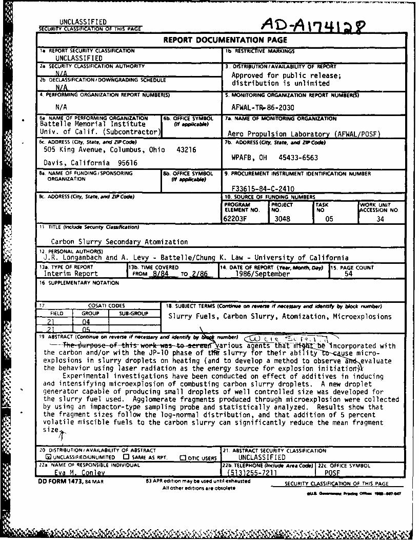
Experimental investigations have been conducted on effect of additives in inducingand intensifying microexplosion of combusting carbon slurry droplets. A new dropletgenerator capable of producing small droplets of well controlled size was developed forthe slurry fuel used. Agglomerate fragments produced through microexplosion were collectedby using an impactor-type sampling probe and statistically analyzed. Results show thatthe fragment sizes follow the log-normal distribution, and that addition of 5 percentvolatile miscible fuels to the carbon slurry can significantly reduce the mean fragmentsize .
20 DISTRIBUTION/AVAILABILITY OF ABSTRACT 21, ABSTRACT SECURITY CLASSIFICATION
G3 UNCLASSIFIED/UNLIMITED [3 SAME AS RPT C DTIC USERS UNCLASS IF I ED22a NAME OF RESPONSIBLE INDIVIDUAL 22b TELEPHONE (Include Area Code) 22c. OFFICE SYMBOL
Eva M. Conlev 1 (513)255-7211 1 POSFDO FORM 1473, 84 MAR 83 APR edition may be used until exhausted SECURITY CLASSIFICATION OF THIS PAGE
All other editions are obsolete*tL& Geummqi w mm IUS-4047
. %
SUMMARY
This is a two-part program on ways to achieve secondary atomization
of JP-10/carbon slurry jet fuels. Various agents that might be incorporated
with the carbon and/or with the JP-1O phase of the slurry were screened fortheir ability to cause microexplosions in slurry droplets on heating and a
method to observe and evaluate the behavior using laser radiation as the energy
source for explosion initiation was developed.
Experimental investigations were also conducted on the effect of
volatile additives in inducing and intensifying microexplosion of combusting
carbon slurry droplets. A new droplet generator capable of producing small
droplets of well-controlled size was developed for the slurry fuel used.
Agglomerate fragments produced through microexplosion were collected by using
an impactor-type sampling probe and statistically analyzed. Results show that
the fragment sizes follow log-normal distribution, and that addition of 5
percent volatile miscible fuels to the carbon slurry can significantly reduce
the mean fragment size.
4.
iii
FOREWORD
This report describes two programs conducted under this task. Oneprogram was done under the direction of A. Levy at Battelle Columbus Division,
* and the second program was conducted by Professor C. K. Law at the Universityof California, Davis.
V
% %~

TABLE OF CONTENTS
Page
SUMMARY ....................................................... i
FOREWORD ...................................................... ii
I. INTRODUCTION ............................................. 1
I . BACKGROUND ............................................... 2
1. General ............................................... 2
2. Microexplosions in Miscible Mixtures .................. 4
3. Microexplosions in Non-Miscible Mixtures .............. 5
III. EXPLOSIVE ADDITIVE STUDIES ................................ 7
1. Results ............................................... 7
1.1 Previous Work .................................... 7
1.2 Laser Ignition ................................... 8
1.3 Experimental Method........................... 10
1.4 Carbon Slurry-Jet Fuel ........................... 10
1.5 Explosives ....................................... 11
1.6 Continuous-Laser Apparatus ....................... 11
1.7 Pulsed-Laser Apparatus ........................... 14
1.8 Carbon-Slurry Drop-Size Measurements ............. 14
1.9 Initial Continuous-Wave Laser Tests .............. 14
1.10 Initial Carbon Slurry Fuel/Additive Test ......... 15
1.11 Pure Additive Tests .............................. 17
1.12 Additive Tests With Added Carbon-Slurry Fuel ..... 21
1.13 Initial Pulsed Laser Tests ....................... 21
1.14 Pulsed Laser Tests With Glass Enclosed Samples... 24
vii
;; ~ ~ -11. I n 1
TABLE OF CONTENTS (Continued)
Page
1.15 Flat-Flame Combustion Experiment ................. 24
2. Discussion......................................... 26
3. Explosive Additive Conclusions........................ 27
4. Postscript......................................... 27
IV. VOLATILE ADDITIVE STUDIES............................... 28
1. Results and Discussion.............................. 28
1.1 Droplet Explosion Temperature Studies............. 29
1.2 Droplet Combustion Experiments ................... 31
2. Volatile Additive Conclusions......................... 52
3. Volatile Additive Recommnendations..................... 52
V. ACKNOWLEDGEMENTS....................................... 52
VI. REFERENCES ............................................ 53
viii
LIST OF FIGURES
Page
Figure 1. Continuous Laser Apparatus ............................ 13
Figure 2A. Carbon Slurry Fuel, 100 ms Laser Pulse Time .......... 16
Figure 2B. Multiple Exposure, Carbon Slurry Fuel, 150ms Laser Pulse Time .................................. 16
Figure 3. Carbon Slurry Fuel/NH 4 N03/TNT/H20. LaserPulse Time - 200 ms ................................... 18
Figure 4. Carbon Slurry Fuel/MeOH Laser Pulse Time =looms ................................................. 19
Figure 5. Schematic of Apparatus Used to Measure ExplosionTemperatures of the Test Fuels ........................ 30
Figure 6. Explosion Temperature of JP-10 Carbon SlurryFuel .................................................. 32
Figure 7. Explosive Temperatures of Cyclohexane Doped withCarbon Slurry ......................................... 33
Figure 8. Explosion Temperatures of Decane Doped with Carbon- Slurry ................................................ 34
Figure 9. Explosion Temperatures of Octane Doped with CarbonSlurry ................................................ 35
Figure 10. Explosion Temperature of 50-50% Heptane-HexadecaneDoped with Carbon Slurry ............................. 36
Figure 11. Explosion Temperatures of Carbon Slurry (22% Carbonby Weight) Doped with Volatile Fuels ................. 37
Figure 12. Schematic of Diaphragm-Based Droplet Generator forSlurry Fuels ......................................... 39
Figure 13. Schematic of the Freely-Falling Droplet CombustionApparatus ............................................ 40
Figure 14. Cascade Particulate Sampling Probe ................... 41
Figure 15. Count Fraction of Exploded Fragments of CarbonSlurry Droplets Doped with 5% Pentane ................ 43
Figure 16. Count Fraction of Exploded Fragments of CarbonSlurry Droplets Doped with 5% Hexane ................. 44
ix
LIST OF FIGURES (Continued)
Page
Figure 17. Count Fraction of Exploded Fragments of CarbonSlurry Droplets Doped with 5% Heptane ................ 45
Figure 18. Count Fraction of Exploded Fragments of CarbonSlurry Droplets Doped with 5% Ethanol ................ 46
Figure 19. Count Fraction of Exploded Fragments of CarbonSlurry Droplets Doped with 5% Ethyl Ether ............ 47
Figure 20. Count Cumulative Plot for Carbon Slurry Dopedwith Pentane, Hexane, and Heptane .................... 48
Figure 21. Count Cumulative Plot for Carbon Slurry Dopedwith Ethanol and Ethyl Ether ......................... 49
Figure 22. Count Cumulative Plot for Carbon SlurryEmulsified with Various Amounts of Water ............. 50
X
LIST OF TABLES
Table 1. Properties of Explosives ....... ... ... .. 12
Table 2. Summary of Detonation Studies on Pure ExplosivesUsing a 50 W CW C02 Laser Under Argon ..... ...... 20
Table 3. Summary of Detonation Studies on 1:1 Mixtures ofExplosive and Carbon Slurry Fuel Using a 50 W CWC02 Laser Under Argon ....... ............... 22
Table 4. Summary of Results on Coated Explosive SamplesUsing Nd-Yag Laser ....... .................. 23
Table 5. Summary of Results Using Nd-Yag Pulsed Laser at 1Joule/25 ms With Samples Behind Glass Plugged withSodium Silicate ..... .................... ... 25
Xi
Mo
SCHOLARLY RESEARCH PROGRAM
Carbon Slurry Secondary Atomization
by
J. R. Longanbach, A. Levy and Chung K. Law
I. INTRODUCTION
As a means of improving the range and payload of cruise missiles,
the Air Force is developing fuels with high-volumetric energy content. To
increase the energy content of these fuels from their current peak level of
about 160,000 Btu/gal to a desired 180,000 Btu/gal, the Air Force has developed
a series of solid-carbon slurry fuels using JP-10. A 180,000-Btu/gal carbon
slurry-jet fuel requires approximately 63-weight-percent carbon load.
Ultimately a successful slurry fuel must possess 5-year storage
stability, fluidity down to -65 F, high Btu/gal heat of combustion, and a
combustion efficiency greater than 99 percent. Several reasonably stable,
low-viscosity carbon slurry-fuels have been developed. A critical problem at
the moment is combustion efficiency. Burnout of carbon in a slurry lags the
vaporization and burnout of the JP-10. This results in unburnt carbon in the
exhaust with resultant combustion efficiencies of 95 percent or less. We well
recognized from past work with these slurry jet fuels, and from work with
coal-water mixtures, that agglomeration of carbon particles in the former
instance and coal particles in the latter occurs. To improve the efficiency
the size of slurry droplets emanating from the fuel nozzle must be decreased.
This required improved atomization. One solution is secondary atomization of
the primary slurry droplet. This program is directed to this topic of secondary
atomization of carbon slurry-jet fuels.
Two methods have been studied to induce secondary atomization. In
the studies by Professor Law, volatile additives have been incorporated within
the droplet. For suitable components and composition, rapid gasification
within the droplet interior can occur spontaneously, leading to intense
internal pressure build-up and consequently catastrophic fragmentation of the
droplet. The primary objective has been to explore the efficiencies of
various additives in inducing and intensifying droplet microexplosion.
'% .
* Two companion experiments have also been conducted, respectivelyinvolving
determining the liquid temperature at the state of gasification, and measuring
the fragment statistics due to microexplosion of freely-falling droplets.
In the studies by Battelle, explosive compounds were added to carbon-slurry
* ., ~ jet fuel droplets and attempts were made to detonate them either by rapidly
increasing the temperature with energy input from a continuous laser, or
by inducing a shock wave in the sample by energy input from a pulsed laser.
% II. BACKGROUND
1. General
The subject of secondary atomization relates to the combustion
of two types of carbon fuels today, which are similar in some ways and possibly
dissimilar in other ways. The two slurry fuels are carbon slurry jet fuel
and coal-oil-water fuels for utilization in furnaces and boilers. The carbon
slurry jet fuel is typified by a highly refined carbon, at a concentration
of 55-65 percent, and ground to 1-5 pmi, in a highly refined fuel such as
JP-10. The coal slurry fuel may be 60-70 percent coal in an oil (possibly
a No. 6 oil) and more recently in water. The coal particles are usually
N: ground to 70 percent -200 mesh (<74 gmi).In either instance, the carbon slurry fuel is atomized as a spray;
the fuel droplets then penetrate into the combustion interior, react with
hot oxidizing air, and so undergo vaporization and combustion. Combustion
of the JP-10 portion of the fuel spray is a vapor phase reaction. As a con-
sequence, as the JP-10 is volatized and consumed, the carbon particles are
further concentrated in the droplet and tend to agglomerate. This results
in longer combustion times and in some inefficiency, as some particles go
* through unburned. The problem may be further exacerbated for carbon slurry
jet fuels since the more refined the carbon, often the less hydrogen attached
to it, making it more difficult to burn the carbon particles.
One possible solution to the carbon particle agglomeration problem
is to promote secondary atomization processes, i.e., add an ingredient to
the fuel to essentially explode the fuel droplet into smaller droplets.
The overall effectiveness of this procedure has been demonstrated for many
2
years. Three earlier references to this procedure are those of several Russian
investigators who showed that residual oils burned cleaner upon emulsifying
the fuel oil with water so that the entrained water exploded to help disperse
and open up the cenospheres for better combustion.( 1,2,3)
In more recent times, C. K. Law, F. L. Dryer, and others have examined
secondary atomization in more depth. In considering secondary atomization,
reference is made to three types of processes: disruptive combustion,
microexplosion, and scattering. The differences in these three processes may
be more semantic than real.
C. K. Law analyzes the combustion of coal slurries by considering
quiescent combustion and disruptive combustion.(4) In quiescent combustion.
Law presents a system in which mixing in the droplet is rapid. Internal
circulation is of sufficient intensity that temperature and concentrations are
uniform. This leads to more volatile components being preferentially removed,
leaving behind a droplet with less volatiles and a higher concentration of
coal. This leads to agglomeration. As Law points out, a 100-pm droplet
containing 1 percent coal will yield a 20-im agglomerate. This agglomerate
size becomes essentially independent of initial particle size.
If internal circulation is mild, diffusion rather than convection
becomes the dominant mode of transport within the droplet. To illustrate this
effect, Law considers a droplet of two miscible liquids with vastly different
volatilities. In this system, if the heat diffusion rate is a couple of orders
of magnitude faster than the mass diffusion rate, i.e., the Lewis number is
significantly >1, say 5-10, then one begins to superheat the low boiling point
liquid in the center of the droplet, and the result is an explosion of the
droplet, i.e., secondary atomization, producing many smaller droplets.
Yap, Kennedy, and Dryer have recently discussed this same topic and
the attempts to distinguish between disruptive burning and microexplosion(5).
In discussing the proposition of a "toroidal vortex model", as a more accurate
description of the liquid phase for analyzing the behavior of water in
hexadecane emulsion systems, Yap et al. state "the term 'disruptive' burning
is reserved for describing the internal vaporization within multi-component
solution droplets, whereas the term 'micro-explosive' combustion refers to
the much more rapid internal vaporization of water droplets occurring within
emulsified fuel drops." Using these definitions, the nature of the
multicomponent fuel must be questioned. Lasheras et al. state "for disruptive
itj 3
burning to occur, not only a minimum difference between magnitude of the boiling
points of the component must exist, but the relative quantitites of the
components must fall within a certain range dependent on the mixture
constituents*.( 6) It may follow from this that a two-component, solid-liquid
slurry cannot be analyzed in the same manner as a multicomponent solid
two-liquid slurry--a point that may bear closer scrutiny relative to the
experiments being reported.
2. Microexolosions in Miscible Mixtures
Several investigators have observed that solvent refined coal (SRC)
burns "disruptively." Kramlich, Seeker and Payne identified at least two
sources for this behavior.(7) When SRCII heavy distillate is mixed with
heptane, the heptane boils as the fuel mixture droplets heat up, breaking up
the fuel droplet to produce a new set of smaller droplets. This process is
called secondary atomization. Thus, SRC produces soot particles, as do the
unblended fuels, and the soot particles terminate in microexplosions.
The second explosive process generally occurs in one or two directions
only, is violent enough to disperse the entire particle, and occurs in every
particle. Called droplet dispersion, Kramlich, Seeker, and Payne found that
this reaction occurred for each fuel type studied, with the exception of pure
heptane which terminated by evaporization, and an Indonestan/Malasian crude
which contained a very high asphaltene concentration and terminated by
censophere formation. The mechanism of droplet dispersion may include coking
to produce volatiles which then boil to produce a microexplosion of the solid
particles.
In an early study of secondary atomization in hydrocarbon blends,
Lasheras, Fernandez-Pello and Dryer showed that vaporization-disruption can
occur only when (1) a thermal transfer is faster than mass transfer (high
Lewis number) so that the internal volume of the particle will heat more rapidly
than diffusion-evaporation can occur, and (2) one component has a higher boiling
point than the superheat limit of the lower boiling component, so that a liquid
phase will exist to hold the bubble together during heating.(6) This means
that secondary atomization can be induced or suppressed by controlling the
composition and boiling point ranges of the components in a mixture and the
external pressure in the system. The presence of a filament to suspend the
4
drop, as has been practiced in some experimental studies, alters the nucleation
and heat transfer processes. The net effect is to increase the intensity of
secondary atomization.
Gallahalli showed that in freely falling drops the time to disruption,
which should be short if a large amount of the drop mass is to be dispersed,
is increased by increasing the drop size and the fraction of the volatile
phase. Methanol-oil drops were shown to burst more vigorously and rapidly
than water-oil drops.( 8)
A theory and model which describe secondary atomization processes
in two-component mixtures have been developed by Law.(9) In a subsequent
review Law also predicted that the secondary atomization effect would be
increased at higher pressure because the boiling temperature of the volatile
phase would be raised, but the limits of superheat would be affected only
slightly.(10) This was subsequently confirmed for both miscible, multicomponent
mixtures and water/oil emulsion droplets.(11) A final observation on miscible
multicomponent mixture microexplosions is the visual observation, reported by
Law, of two nucleation bubbles in a single droplet. The location of these
bubbles in the droplet shows that homogeneous nucleation of volatilization
occurs on a spherical surface within the particle where the superheat conditions
are favorable, rather than in the center of the droplet.(12)
3. Microexolosions in Non-Miscible Mixtures
Law et al, have extended their multicomponent studies to coal/oil
and coal/oil water mixtures.( 13) The combustion characteristics of coal/oil
mixtures are dependent on the internal mixing in the droplets. At the rapid-
mixing limit, the volatile components are able to get to the surface and
evaporate, so that batch distillation occurs and the non-volatile coal particles
agglomerate. Agglomeration can be significant even at low coal loadings. A
1O0-um droplet containing 1 percent coal particles will produce 20-m
agglomerate.(13) When internal circulation is weakdiffusion is rate limiting.
The coal particles can serve as nucleation sites for internal boiling.
Fragmentation of the droplet occurs and can occur again when the smaller
droplets are formed by secondary atomization. To obtain these conditions the
droplet should be small, the oil should be viscous and should contain high
and low boiling components.
S
The addition of a small amount of water can be used as an alternative
method to induce secondary atomization. Initiation of water boiling isinsensitive to internal motion and fuel composition. Since small amounts of
water are normally present in coal, no special effort may be necessary to
introduce water. The presence of 5 percent water in a coal/oil/water emulsion
stabilizes the emulsion and causes early anad violent secondary atomization.The coal particles do not have to be ground fine. Particle burning time is
not dependent on initial particle size.
Studies of the coal/oil mixtures suspended from fine wires in a heated
atmosphere suggest that the addition of methanol would be useful to shorten
the ignition delay time and that the addition of water might effectively
initiate secondary atomization by microexplosion, which leads to shortening
of the overall combustion time.(14)
Combustion of coal/methanol slurries (CMS5) has also been studied. There
is some interest in these slurries because of the low freezing point of methanol
which would allow transportation of the slurries through a pipeline in a cold
climate. Emissions of NOx and SOx would also be decreased by burning CMS.
Studies testing droplets suspended on a wire, or in a platinum basket in a
hot atmosphere, show that combustion occurs in two stages. The coal volatile
matter and methanol burn in the first stage, scattering the coal particles in
the process. This scattering is different from secondary atomization. The
particles then burn rapidly because they are finely dispersed. During particle
burning no disruptive burning was observed.(15)
6
III. EXPLOSIVE ADDITIVE STUDIES
1, Results
1.1 Previous Work
The use of explosives incorporated in a carbon-slurry fuel to enhance
atomization has also been studied, although much less extensively than the
use of volatile additives. All of the normally obtainable and suitable"explosives" are chemically stable at ambient conditions. Obtaining an
explosion rather than mere burning of a chemically stable compound can be a
complex and difficult task requiring the achievement of a very specific set of
reaction conditions.
Early studies of the explosive behavior of methyl nitrate vapor in
the presence of oxygen and an inert gas in a heated tube illustrate some of
the problems.(16) Normally, an exothermic reaction must self heat to a
temperature above the surroundings to accelerate the chemical change. Loss of
heat to convection and conduction opposes the process. Therefore, dilution
with inert gases might be expected to quench ignition. But in the case of
methyl nitrate, the presence of nitrogen or argon in all concentrations
increases the tendency to explode because self heating is of secondary
importance. The explosion develops by a chainbranching mechanism and diffusion
to the walls, which is inhibited by the presence of an inert gas, is the
principal quenching mechanism. The half-life for thermal decomposition of
methyl nitrate varies from 5 seconds at 275 C to 2 ms at 425 C. Above 300 C
all of the methyl nitrate decomposes during the induction period and the
explosion occurs in a mixture of nitrogen dioxide, methyl alcohol and
formaldehyde.
At least one instance of "chemically enhanced" combustion of a water
slurry-fuel has been published. In a recent patent, Olen suggests the use of
100 to 5000 ppm of a water soluble explosive taken from picric acid, alkali
picrates and heavy metal picrates, guanidine and nitroguanidine in a 65 to 80
percent coal/20-35 percent water composition to detonate early in the combustion
process, producing a secondary dispersion of fuel particles.(17) Unfortunately,
this patent does not appear to have been experimentally verified.
7
There is a large amount of literature on explosives, which have
been a subject of active study in many nations since black powder was introduced
in Europe around 1250 A.D. Explosives are characterized by rapid reaction
times, generally 10-6 seconds and the production of large volumes of gas.
The rate is controlled by shock transfer and initiation occurs either by
temperature or shock with an activation energy of typically 30 to 60 kcal/mole.
The shock wave intensity depends on confinement, density of materials and
geometry.
Explosive types include primary, secondary, high explosive and
propellant in order of decreasing sensitivity to energy input. Only a few
ingredients are used because of safety and cost. Accessibility further limits
the number of explosives available for a study such as this one.
1.2 Laser Ignition
Heat to cause ignition can be introduced by convection and/or
radiation. In the present program it was decided to use laser ignition.
Light from all lasers is highly monochromatic and coherent; the beam is
perfectly parallel, easily controlled and directed using shutters, lenses and
mirrors.
Realization of the potential of using lasers to induce
heating/pyrolysis in soltds,( 18,19 ) to ignite fuel gases (20) or droplets and
to initiate deterioration (21) date to 1967-1968. Lasers have a number of
advantages in attempting to achieve point ignition. Energy release can occur
in a very short time, or in a very small area, and the quantity of energy can
be measured accurately.(22)
Early experiments on the pyrolysis of finely divided coal using a
15-kw continuous CO2 laser (10.6um) showed that the heating processes in the
particles can be decoupled from secondary reactions which occur due to thepresence of a hot gaseous atmosphere. The use of laser heating also
eliminates the need for a hot wall structure and allows better control of the
time-temperature profile and gaseous atmosphere present at the particle
surface.(23) Heating rates of 105 K/s and temperatures of 1300-1800 K can beachieved, which simulates pulverized fuel combustion or entrained flow
gasification conditions. However, with small particles heat loss is rapid
8
I;h
e e , w
i h s m l t e
u v r z d f e
o b u t o r e t a n d
f o
and the heating behavior of the particle follows roughly the heat input from
the laser beam.
Using more complex experimental arrangements, it has been possible
to irradiate free falling particles with a pulsed laser beam to obtain mass
spectra of fragmented individual aerosol particles.( 24) A Nd-YAG laser has
been used to fragment organic or inorganic ions using a pulse of 2 J of energy
in less than 100 ps. The use of a freely moving particle avoids substrate-
particle interaction, including conductive heat loss.
Inducing detonation of a single substance or mixture can be difficult.
For instance, the mechanism of breakdown in methane-air mixtures caused by
the very rapid energy input from a laser has been found to be very complex.
The point facing the beam absorbs the incoming energy which leads to the
formation of an asymmetrical initiating source with energy in excess of that
needed for ignition, and possibly capable of forming a blast wave which may
be powerful enough to cause detonation.(25)
However, simply adding a large amount of energy to a small point
on the surface of a carbon particle is not sufficient to insure combustion.
In a study of laser-ignition of electrode carbon particles in a nitrogen-oxygen
' -atmosphere, Ubhayaker and Williams showed that small carbon particles routinely
extinguished without significant burning after laser ignition.(2 6 ) The surface
oxidation reaction to produce CO has an Arrhenius activation energy of 18
kcal/mole and an order of 0.5-1.0. Variation in the oxygen fraction (0.5-1.0)
and pressure (0.5-3 atm) showed that the burning rate is oxygen-diffusion
controlled and, as the particle size (50-200 Vm) decreases, the reaction
rate becomes smaller than the diffusion rate, causing extinction. This occurs
even though the surface temperature is raised to vaporization temperature
(4500 K) via a 35 J pulsed ruby laser.
A study has been reported on the burning of dried agglomerates
from carbon-slurry fuels.( 27 ) Agglomerates having diameters of 750 PM were
supported in the post-flame region of a flat flame burner. These studies
predicted the lifetimes of carbon-black slurry drops in environments typical
of combustion chambers. The work included several carbon-black formulations,
initial drops sizes from 10-1000 gm, fuel equivalence ratios of 0.2-1.4 and
temperatures of 800-1950 K at atmospheric pressure. The two-stage combustion
process consisted of (1) heatup and gasification of the liquid fuel leaving
9
the slurry particles in the drop as a porous agglomerate, and (2) the agglom-
erate reaction stage which lasts an order of magnitude longer and is the
rate controlling step for complete combustion. Although the addition of
lead was found to increase the agglomerate burning rate by as much as a factor
of two, the study concluded that attention should be focussed on improving
atomization of the agglomerates.(27 )
1.3 Experimental Method
The experimental program consisted of obtaining a sample of carbon-
slurry jet fuel from the U.S. Air Force and adding a variety of explosives
to it. Small drops of the slurry were supported in several ways in the path
of a laser and exposed to continuous radiation, using a C02 laser or a pulse
of radiation from a Nd-YAG laser. Energy output was monitored by an infrared-
sensitive diode in the case of the continuous laser and by a microcalorimeter
when the pulsed laser was used. The experiments were also monitored visually.
Various agents that could be incorporated with the carbon and/or
with the JP-1O phase of the slurry were screened for their ability to cause
microexplosions in slurry droplets on heating. Solid organic nitrates, for
instance RDX or TNT, were incorporated at low percentages into the slurry.
Droplets, some suspended from quartz fibers, were exposed to laser radiation
to initiate the microexplosion. The explosions or change in the droplets
were observed visually and by recording temperature changes.
1.4 Carbon Slurry-Jet Fuel
A sample of carbon dispersion fuel was received from personnel
at Wright-Patterson Air Force Base. The sample was produced at Sun Tech,
Inc., Marcus Hook, PA. The sample had a stated flash point of 125 F and
was labelled as follows:
SF-2 (783)
83-POSF-1275 McCoy.
A preliminary experiment showed that the fuel could be passed through a 0.25
nn quartz capillary using a disposable syringe as the driving force. This
technique produces drops having a radius of about 819 im which are within
10
the calculated size range which could be vaporized by the 90 W laser beam in
less than 100 milliseconds, using the vaporization of water as a model for the
heat requirement.
1.5 Exolosives
Table 1 lists the properties of the explosives used in this study.
They range from oxidizers to a possible primary explosive. Most are secondary
explosives, available commercially because they are not very sensitive to
impact, shock and elevated temperature. For instance, ammonium picrate has
been used in armor-piercing gun projectiles because of its insensitivity to
impact and shock.(28) TNT is relatively insensitive to impact, friction,
shock and electrostatic energy. It has been fired in high-acceleration gun
projectiles with reported premature rates of less than one in a million.(28)
The detonation temperature of tetryl is reported to be 2915 K(28)
and the detonation pressure of TNT is 18.9 GPa (130,000,000 psi).(28 )
Thus, it was not expected to be an easy task to detonate these
explosives in a carbon slurry via laser radiation, either by rapid heatup or
by generation of a shock wave.
1.6 Continuous-Laser Aooaratus
A 90-W CW CO2 laser was selected for use initially. A small (4 in.
x 5 in.) box to house the droplet holder was constructed of Lucite. Lucite
is opaque to the 10.6 pm CO2 laser beam and allows the experiments to be
monitored visually.
A diagram of the apparatus is shown in Figure 1. It consisted of a
1-inch diameter electronically-operated silver-alloy coated shutter (A.W.
Vincent Assoc.) which could be opened for a time from 6 ms to infinity. The
laser beam reflected to a firebrick when the shutter was closed. When opened,
the beam passed through a germanium beam splitter (1-inch diameter x 2 mm) and
was reflected by mirrors and focused on opposite sides of the sample through
two 1-inch-diameter F4 lenses, and 19.05-mm-diameter windows, both made of
BaF 2. The sample was held on the end of a stainless steel needle or
quartz tube suspended from a 1-ml disposable syringe. The droplet could
11
CL u C U U
16 th U U U w
LJ 0 "JC tj (JC
- - p- P-41 £ c
0 L x ' x 0
CL 1 . .
U..
Cp0
L
9-
o Cj
0
010
Go 0% 0%G
at 0
06 0I
V 0 _
S- qw4# L"a .N1 GA
z = 00IC = a
12
00
UL
31
Llai~lleal -.
be centered in the laser beam by various set screws on the syringe holder
assembly.
The infrared light from heating of the sample drop was collected on
a diode, placed normal to the direction of the laser beam and covered with a
piece of acetate which would not pass reflected 10.6 im laser radiation. The
heat output to the diode was recorded on an oscilloscope and the trace was
photographed with a Polaroid camera over a time-intensity grid to obtain a
permanent record. The oscilloscope sweep was triggered by opening the shutter.
In later experiments, a Norland 2001A programmable oscilloscope was
used to digitally collect and average multiple heat traces to measure averaged
heat output versus time.
1.7 Pulsed-Laser Aooaratus
A Nd-YAG (Neodymium-Yttrium Aluminum Garnet) pulsed laser which
supplied one Joule of energy at 1.06 Pm in a single 25-nanosecond pulse was
used. The focus was very narrow, 1 mm. A microcalorimeter was placed about
10 cm from the sample to measure the energy emitted by the explosion. A narrow
band pass filter removed any reflected 1.06-um radiation.
1.8 Carbon-Slurry Droo-Size Measurements
Tests with 0.25-mm- and 0.32-mm-ID fused silica tubing showed that
the carbon slurry fuel sample could pass through the tubing. Average drop
sizes formed were 820 and 1040Mm radius, respectively, based on the average
weight of 10 drops from each tubing size, and a slurry bulk density of 1.24
g/ml at room temperature.
1.9 Initial Continuous-Wave Laser Tests
A number of problems had to be solved initially with the continuous
wave laser and sample holder. The power of the CW CO2 laser was measured at
50 W rather than the rated output of 90 W. The variation in power output
over time seemed to be minor.
14
The initial focus of the beam was very small. The laser beam seemed
to "drill a hole" in the droplets. The focus was widened as much as possible
without significant changes in the apparatus.
The fused silica 0.25-rmm-ID capillaries, used initially to hold the
droplets, tended to fuse shut whenever they were inadvertently struck by the
laser beam. These were replaced by stainless steel needles (0.1-rn ID) which
reflected the beam rather than fusing. Whenever a sample burned, the liquid
sample in the needle was evaporated by the heat, plugging the needle. A stream
of nitrogen was used to purge the system to avoid fires. Since the purpose
of the CW laser was to cause detonation rather than combustion by rapid heat ing,
the use of an inert atmosphere did not significantly compromise the objective
of the experiment. It was observed that slurry droplets became white not at
the point of laser impact in less than 100 ins.
Drops were frequently knocked off of the needle by gas evrO ution
resulting from sample vaporization. A small stand topped with~ d Luc'te
pedestal, which could be raised into the laser beam. was ailt to fit inside
the sample chamber so that drops of liquids and small pieces of solids could
be held in the beam in some of the later tests.
1.10 Initial Carbon-Slurry Fuel/Additive Test
Initial attempts were made to detonate a mixture of 9:1 carbon slurry
fuel/ammonium nitrate. These mixtures seemed to produce sparks when compared
to the carbon-slurry fuel alone but did not explode.
The tests were done with drops from stainless steel needles using
about one-third of the falling-drop volume. At short pulse times (100 ins)
heat emissions, as measured by the oscilloscope trace, rose and held nearly
constant for the duration of the laser radiation input. This may have been
due to evaporation of the JP-10 fuel in the slurry. At longer times (1000 mns)
the heat output was low at first and then jumped sharply. This may have been
due to completion of evaporation followed by heating of the carbon residue.
Multiple tests appeared to confirm that the heat output curve was roughly
reproducible. Examples are shown in Figures 2A and 2B. It should be notedthat the diode had a 15V saturation limit which was reached during one of the
heat "spikes," causing the flat spot in Figure 2B.
15
. . . . ... . . .
JHea- n - - - - - --+-- -4
- - -
I'
" . .. .-
500 400 300 200 100 0
Time, ms
FIGURE 2A. CARBON SLURRY FUEL, 100 MS LASER PULSE TI1E
.. . . . . . .. ..
"Heat
- - -i1 - - I
I I !
I I
_ I500 400 300 200 100 0
Time, ms
FIGURE 2B. MULTIPLE EXPOSURE, CARBON SLURRY FUEL, 150 ms LASER PULSE TIME
16
S , ., - - -, . -- -. - . ' . . . * .. . . . . . ' ~ . .' . %~a,.
Similar experiments with carbon slurry fuel/TNT/NH4NO3/H20 mixtures
showed essentially the same behavior. TNT could not be exploded under these
experimental conditions. A typical heat trace is shown in Figure 3.
One test with methanol added to the carbon slurry suggested that
evaporation took place, but the heat output was lower, perhaps due to the
lower boiling point of methanol. (Figure 4).
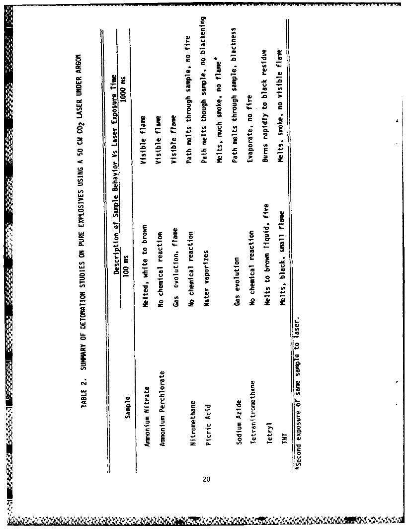
1.11 Pure Additive Tests
Since there is no evidence to indicate that detonation was occurring
using the additive-fuel mlxtures~it was decided to try to detonate pure additives.
Two series of tests were conducted to see if pure additives could be caused
to explode by laser irradiation using the 50 W CW C02 laser. In the first
series the additives, most of which were solids, were dissolved in solvents,
either acetone or water, and suspended from a needle or soaked onto paper
and held in an argon atmosphere in the laser path. None of the additives
exploded. Several didn't even burn rapidly in the argon atmosphere at laser
irradiation times up to 1000 ins, possibly due to the lack of stoichiometric
amounts of oxygen.
The drops were frequently knocked off the needle by gas evolution
resulting from solvent evaporation. Solvent evaporation dominated the reaction
sequence. Irradiation of pure additives was needed.
A small stand topped with a Lucite pedestal was built to fit the
laser sample chamber so drops of pure liquids and small amounts of pure solids
could be placed in the laser beam.
The second series of tests were conducted to see if pure additives
could be detonated by laser irradiation using the 50 W CW C02 laser under
solvent-free conditions. Several additives burned, but none exploded. None
continued to burn under argon after the laser pulse stopped, again possibly
due to the absence of oxygen, but also possibly because heat loss was too
rapid. Some melted or gave off smoke. Tetryl, a high explosive, was the
most active material.A summnary of the result of the pure explosive tests is listed in
Table 2.
17
Heat
500 400 300 200 100 0
Time, ms
FIGURE 3. CARBON SLURRY FUEL/NH 4NO3 /TNT/H20, LASER PULSE TIME = 200 ms
18
a o
W ~ ~ a .. a.,,- - -
-4-4---4-4---- -- 4494 H1
,a,
500 400 300 200 100Time, ms
FIGURE 4. CARBON SLURRY FUEL/MeOH LASER PULSE TIME 100 ms
19
...........
W w YWUc
c
a c nCAU
.0 30oI to IM mU
an'a
41 .0 16 03en~V g. . a- 0
E 4A 4 0%A 4A 4 4041
Q6 01 W
~ L.
9L 41 4.1 41
C)J
4n M. IV Wn U4)- =a 1.- 0) =5~ 45 0
0 oo00
LL.0
006
4n I E
o so.
00
1en 0303 03
La. 41 0 .
4.07 E 41 0C CE 4
41 41 $.-
I ila L0
02
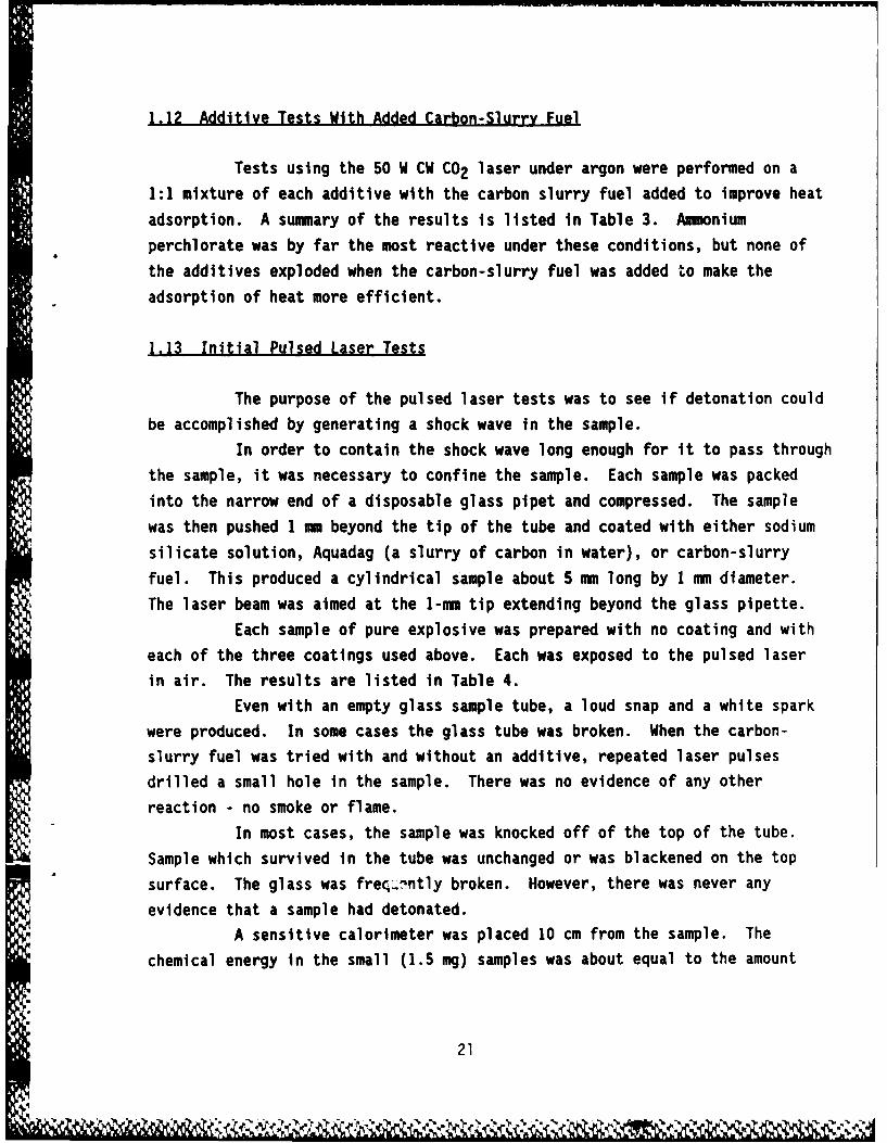
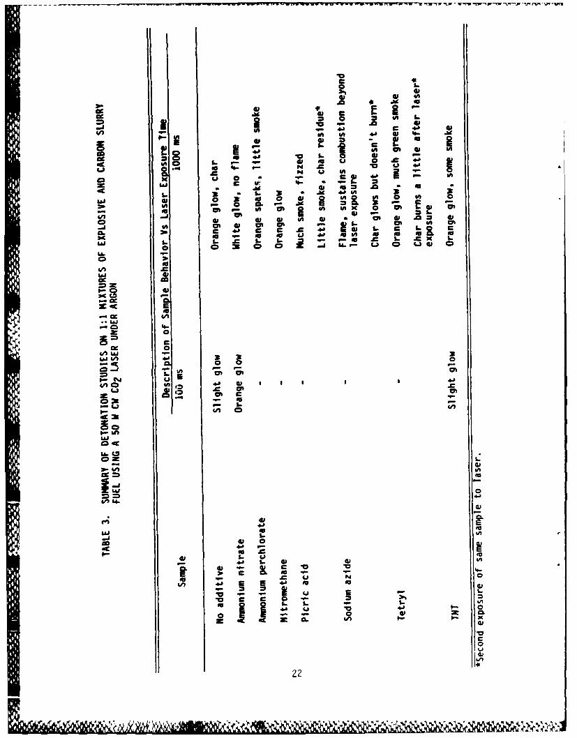
1.12 Additive Tests With Added Carbon-Slurry Fuel
Tests using the 50 W CW C02 laser under argon were performed on a
1:1 mixture of each additive with the carbon slurry fuel added to improve heat
adsorption. A sunmmary of the results is listed in Table 3. Ammnonium
perchlorate was by far the most reactive under these conditions, but none of
the additives exploded when the carbon-slurry fuel was added to make the
adsorption of heat more efficient.
1.13 Initial Pulsed Laser Tests
The purpose of the pulsed laser tests was to see if detonation could
be accomplished by generating a shock wave in the sample.
In order to contain the shock wave long enough for it to pass through
the sample, it was necessary to confine the sample. Each sample was packed
into the narrow end of a disposable glass pipet and compressed. The sample
was then pushed 1 -m beyond the tip of the tube and coated with either sodium
silicate solution, Aquadag (a slurry of carbon in water), or carbon-slurry
fuel. This produced a cylindrical sample about 5nmm long by 1 -m diameter.
The laser beam was aimed at the 1-nun tip extending beyond the glass pipette.
Each sample of pure explosive was prepared with no coating and with
each of the three coatings used above. Each was exposed to the pulsed laser
in air. The results are listed in Table 4.
Even with an empty glass sample tube, a loud snap and a white spark
were produced. In some cases the glass tube was broken. When the carbon-
slurry fuel was tried with and without an additive, repeated laser pulses
drilled a small hole in the sample. There was no evidence of any other
reaction - no smoke or flame.
In most cases, the sample was knocked off of the top of the tube.
Sample which survived in the tube was unchanged or was blackened on the top
surface. The glass was freq-.nntly broken. However, there was never any
evidence that a sample had detonated.
A sensitive calorimeter was placed 10 cm from the sample. The
chemical energy in the small (1.5 mg) samples was about equal to the amount
21
.0
V- C .0in E 4A IV 46. .
4.0 W Ch
IN IA
ig 0 a in
S . J9* j bIA 3; o
LaJ41lu 0 Af v) U, i a iIA P.- .9 x V-
Ia Wy 4A C71 giA IA~ x 0.L
6n im 4 4 n 41 * 41 z 1
Ii cyl 4 CP i V- L. mi on C71CL. 44 a c 4.0 IV L. C L
m0 f 0 0 w 4.' 1 0 0O r- . 0-
uJ L 6.. . u- 2 I. Cxo C) 9 C2 0 u.. CD~. tj w 0
01
E
0
C&M Lai
~j L^ 4b 3 3 3
0-11
Is C*I"- Ln
W4.
to41 U I
&no 6'~w
S06. - o
inV0
,a a.4.'6E
UJ 0ILI41 ~ I--11
4.'22
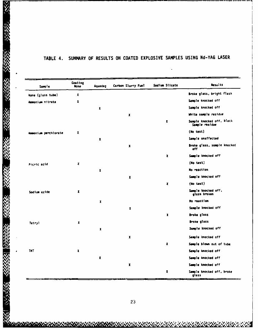
TABLE 4. SUMMARY OF RESULTS ON COATED EXPLOSIVE SAMPLES USING Nd-YAG LASER
CoatingSam'ple None Aquadag Carbon Slurry Fuel Sodium Siicate 3esults
Ndone (glass tube) x Broke glass. bright flash
Ammonium nitrate x Sample knocked off
x Sample knocked off
x White sample residue
x Sample knocked off, blackSample residue
Amumonium perchlorate x (No test)
x Sample unaffected
x Broke glass. sample knockedoff
x Sample knocked off
Picric acid x (NO test)
x No reaction
x Sample knocked off
N (NO test)
Sodium azide x Sample knocked off,glass broken
x No reaction
x Sample knocked off
K Broke glass
Tetryl x Broke glass
x Sample knocked off
x Sample knocked off
x Sample blow out of tube
TNT x Sample knocked off
x Sample knocked off
x Sample knocked off
x Sample knocked off, broke
glass
23
of energy reflected from the sample by the laser striking it. Initially,
the calorimeter could not be used to differentiate between a sample detonation
and the laser reflection.
There did not seem to be much difference between coatings. The
coating did not improve sample integrity by holding the powder samples together.
Sodium silicate reacted with some of the samples. Aquadag seemed to decrease4the response of the sample to the laser. The carbon-slurry fuel itself appeared
to be the best coating for this purpose.
1.14 Pulsed Laser Tests with Glass Enclosed Samples
A second set of samples was prepared by enclosing the sample inside
glass tubes and sealing each end with sodium silicate. In these tests the
laser had to pass through the glass tube wall to strike the sample.
The calorimeter was equipped with a narrow band-pass filter to
remove any reflection of the 1.06 gm laser radiation.
The results of these tests are listed in Table 5. Using samples
prepared in this way there was no evidence of sample reaction. Hitting the
sample tube with the laser invariably broke the glass. It is possible that
most of the laser energy was reflected off the curved glass surface. Flat
plate-sample holders may have been an improvement but were not tried.
There was no significant difference between calorimeter readings,
either between sample types or sizes. The reading levels were well below
what would be expected if a chemical reaction occurred (10-4j). This also
suggests that no explosions took place.
1.15 Flat-Flame Combustion Experiment
Small amounts of each additive were dropped into a flat-flame (Meeker
P burner), enclosed in a glass tube to remove drafts, to see which reacted
most rapidly in an actual combustion environment. Sodium azide particles
caught up in the flame draft burned so rapidly that they appeared to burst
under these conditions. Based on this observation, sodium azide might be
the most effective of the additives tested for promoting secondary atomization.
24
%D6OU
Z LL
LaL
C343
.C 4A
Laa S
L! *9
0503- S
0. 0
to 4. 2 2 A
0.1-
m -9
2. Discussion
The results of this investigation are negative in that none of
the *explosive" additives screened promoted secondary atomization of a carbon-
JP10 fuel slurry droplet. Due to the brief nature of this investigation,
it bears consideration whether the results are negative on theoretical (mechan-istic) principles or for lack of sufficient experimental technique (laser
intensity).
By definition secondary atomization refers to the break-up of liquid(slurry) fuel droplets in hot gases due to internal vaporization. Based
on C. K. Law's investigation(9 -10), microexplosions of multicomponent fuel
droplet can be explained through a diffusion-limit model. The primary require-
ments are:- Two miscible liquids of widely varying volatility
- A concentration of the high boiling, less volatile
component on the droplet surface on heating- A high droplet temperature controlled by the surface
composition
- A high Lewis number providing more rapid heat transfer
than mass transfer within the droplet
- Superheating of the high volatile component
- Homogeneous nucleation with rapid gas generation from the
droplet interior, rupturing the droplet into smaller droplets.Since this mechanism depends on the existence of a steep concentration gradient
it is more likely to occur for a droplet with minimum internal circulation.
In the present program, the premise was maintained that instead
of using a wide volatility difference in two miscible liquids to generate* .~ internal droplet pressures, one might incorporate an explosive and cause
the decomposition of the explosive to create the internal fragmentation force.* The results suggest that it apparently was not possible to cause the explosive
to detonate and generate gas within the droplet. In hindsight, one can ask
whether this is possible since the laser must initially deposit energy on
the surface of the opaque particles. If one follows C. K. Law's mechanism
presented earlier, it becomes apparent that the explosive must be maintained
26
in the interior of the droplet (on the basis that the gas evolution from the
explosive would be entrapped in the surrounding slurry-fuel droplet). If this
situation is not achieved then one must question whether homogeneous
decomposition can occur (1) deep within a droplet, and (2) sufficiently early
in the droplet lifetime. As Law shows in his studies these two requirements
are not always satisfied in miscible multicomponent systems with widely varying
volatilities. It would appear that this was also the case when explosives
were incorporated into the slurry droplet.
The above situation notwithstanding, it is also possible that the
experimental approach used in these studies was flawed. Laser radiation was
selected as a means of providing high energy in a short time to minimize
competition between heatup rates and devolatilization rates. It seems likely
that laser radiation did not promote intense internal circulation within the
dropiets so that vaporization resembled surface distillation rather than batch
distillation. In subsequent programs a different experimental design should
be considered, one in which convection heating would be more predominant, such
as in a drop-tube furnace.
3. Exolosive Additive Conclusions
The principal conclusion of this work is that, except under
extraordinary circumstances, typical *explosive" compounds do not explode, and
that the hypothesized method of achieving seondary atomization by adding
explosives in carbon-slurry fuel combustion may not be technically feasible.
Different compounds are more reactive under the various reaction
conditions tried, but no instance of actual detonation was observed in this
work. The actual conditions in a jet engine combustor were not simulated so
no recommendation for an additive to test under these conditions can be made.
4. postscriot
At the conclusion of this study, we had the opportunity to discuss
the results with Dr. Ardeen Walters of Florida Power and Light Corporation,
27
- ~ .w.-wrwr~wv~r- W'WS w TflTry- ~ T I W 7W V 1
Juno Beach, Florida.(29) Dr. Walters has examined this subject of secondary
atomization using explosives to improve the atomization of coal-water slurry
droplets. It is quite possible based on his experience and calculations that
$ the particle size of many explosives may need to be too large to detonate and
shatter droplets. In the case of potassium picrate, he estimates that a crystal
smaller than 300 vrn, about 10 micrograms, requires a mean induction time of
over one second.(30) Hence, a slurry droplet of potassium picrate in a fuel
would not have sufficient time to detonate in the milliseconds in a gas turbine
combustor. Each explosive will have its own requirements for detonations.
It is possible that those selected for this study fall into that class and
will not detonate if smaller than 200-300 Pm. In essence, the requirements
for additive detonation include: critical mass, critical density, size, and
induction time. Any continuing program in this area should attempt to keep
these criteria in mind.
IV. VOLATILE ADDITIVE STUDIES
1. Results and Discussion
Occurrence of microexplosion can be facilitated through severalmajor factors. First, the volatility differentials between the more and less
volatile components should be as wide as possible in that the less volatile
component is needed to drive up the droplet temperature while the more volatile
component is needed for its ease to spontaneously gasify. Second, internal
P gasification is facilitated by the presence of particles, as in slurries,
which provide heterogeneous nucleation sites; without such sites the droplet
would have to be heated to much higher temperatures to initiate homogeneous
nucleation. Third, the intensity of microexplosion appears to be higher for
emulsions, with the volatile component being the dispersed phase, than for a
miscible mixture. The reason is that the dispersed micro-droplets provide
much larger mass elements for the instantaneous conversion to gas.
The carbon slurry of interest is made of carbon black mixed in
JP-10 fuel with the aid of a surfactant of proprietary nature and composition.
Since JP-10 is a pure fuel, and if we temporarily disregard the influence
28
Y'4
of the surfactant, microexplosion of their slurry droplet is not favored.
Therefore, in order to induce microexplosion, additives are needed to make the
liquid fuel multicomponent.
1.1 Droplet Explosion Temperature Studies
There are two characteristic droplet temperatures which are ')f
importance in the present phenomena. The first is the maximum attainable
droplet temperature. For a droplet consisting of only JP-1O and the carbon
powder, this temperature should be limited by the boiling point Tb of JP-1O,
which is 182 C at atmospheric pressure. This temperature should not be
influenced much in the presence of surfactants and small amounts of volatile
additives.The second characteristic, Te, is the one corresponding to the state
at which internal gasification is initiated. For a given mixture composition
at any location within the droplet, Te should be bounded by the boiling point
and the limit of superheat, Te, for that mixture composition; at these two
temperatures heterogeneous and homogeneous nucleation are respectively
initiated.
Based on the above discussions, in order for internal gasification
and thereby microexplosion to take place, a minimum requirement is Te < Tb.
For These two values, Tb is reasonably well defined, allowing for possible
influences due to additives and surfactants. The value of Te, however, is
not known and needs to be experimentally determined.
,The apparatus used to determine Te is shown schematically in Figure5. HerE an upwardly-directed positive temperature gradient is established in
a liquid column by using electrical heating tapes. At the bottom of the column
a droplet of the test liquid, which is immiscible with the column liquid and
,6 also has a lower density, is introduced and rises slowly and steadily due to
buoyancy. For a sufficiently small droplet, say around 1 mm in diameter, the
droplet is in perpetual thermal equilibrium with the column such that its
temperature can be approximated by the local column temperature. Thus, when
the droplet reaches Te and explodes, the value of Te can be determined by
simply measuring the temperature of the column at which explosion takes place.
The crucial feature of this arrangement is that, except for the carbon
29
4, 2 9
"I, .. ,," • ", .. '. (¢ ' "' e " .," "" '-,' ,"',,, , - > ' ,,. .'' ,.". ' '""' .,'.'.\ " .. . .
U-)
LLU
E0 4. CL
4, ea 0 UL W4.)
LL.C)
0 LW
0 S0
>,LUj
ccU
CD
LUJ
LUJ
0V)
V)4~L0(0
0) ~ C,.
0)0)
LLIn
LU-
30
Zo .
powders, no additional solid surfaces, such as those of a thermocouple, are
introduced into the test droplet to falsify the nucleation process in the act
of temperature measurement.
Figure 6 shows the explosion temperatures of JP-10 with various
concentrations of carbon slurry. The limit of superheat for pure JP-10 cannot
be determined because it exceeds the boiling point of the column liquid,
glycerin. The most interesting result here is the reduction of Te with the
addition of small amounts of carbon slurry, although this reduction rapidly
approaches an asymptotic value of about 240 C. Thus, increasing the carbon
loading will not further reduce the explosion temperature.
Figures 7 to 10 show the explosion temperatures of cyclohexane,
decane, octane, and a 50-50 mixture of heptane-hexadecane with small amounts
of carbon slurry addition. The rapid initial decrease followed by an asymptotic
behavior is again observed. Note that this explosion temperature is
intermediate of the limit of superheat temperature and the boiling point.
Furthermore, this asymptotic temperature can be lowered to the boiling point
of JP-10, 182 C, only for fuels whose boiling point is less than that of octane.
Figure 11 shows the explosion temperatures of carbon slurry (22
percent carbon loading by mass) with addition of small amounts of pentane,
hexane, and heptane. Although the addition of these volatiles generally lowers
the explosion temperature, the extent of reduction is not as large as doping
these volatiles with the slurry fuels.
Based on the above results, we conclude that fairly volatile fuel
additives are needed to induce microexplosion of the carbon slurry droplet.
1.2 Droplet Combustion Experiments
Although many experiments have been performed on slurry droplet
combustion, most of them have adopted the suspended droplet technique. The
difficulty with this technique is that the suspension fiber can provide
nucleation sites to induce artificial heterogeneous nucleation and thereby
droplet microexplosion. Thus, an essential requirement for the study of slurry
droplet microexplosion is the use of free droplets. In a previous study of
ours, we have used freely falling droplets, although the droplet sizes were
too large, of the order of 800 um. In the present experiments, the initial
droplet size was fixed at 340 um.
31
C--
00
L-
LLoL
-t CD
z -
0-cc
C)
0.0
- U
Cl.0
-4
0 31n.JdJW.
Ca.. C-32

CC
AA
U
-LA
-4I--
LJ
0~
9 0 aCU * -4
Xz
.Go -44
:)0) vniv~dK3
330
0-
0
C...
0 u C
UjK- 0-
V))
o to
C6LJ
oto
C:C
Co 0 0)co ,e 0 -oC4 -C-4L
DOgviwam
340
..... ....
W c0
0V
0;
.
w LL)
Lii43 V
CL CL
0 0V.I
-4A
0 0
C>UUG0
0) ~~ 3vzVd3
35
e4
oLNC
LM1
aszoa
CA4
- LU
o Lc)
- Ln
00
12.
Li
CD=
0 LA-
Laco
:)d~ LA..v~W
360
I--
CLC-
+) to UIa. x
LjJ
--
CI-
C:
4JJccJ
L.L)J
.4-
au A
q4n Ln~
C)-jCL -
LA..
LAA
CDJ
D CDCDCLn q~r-c
C'. cmJC. C'.) C'.(30) *dwaj UOjLSa~dx3
37
-- 'r.
* The design of the droplet generator is shown in Figure 12. It
basically consists of a diaphragm of piezoceramic crystal pressed against the
fuel reservoir. Upon application of an electric pulse, the crystal deforms,
therefore squeezing a droplet out of the nozzle. The size of the droplet can
be controlled by the size of the nozzle and, to a certain extent, the extentof crystal deformation. The droplet spacing can be controlled by the frequency
of the pulses, and can vary from about two droplet diameters to hundreds of
droplet diameters; in the latter case the droplets can be essentially considered
to be isolated. The droplets then pass through the post-combustion zone of a
flat flame burner, ignite, and burn, as shown in Figure 13 for the overall
experimental schematic. The temperature and oxygen concentration of the
combustion environment can be controlled by changing the compositions of the
A mixture supplied to the flat-flame burner. All the experimental data to be
reported were collected in an environment of 1000 C and 21 mole percent of
oxygen.We found it necessary to project the droplets upward because in the
downward orientation slight settlement of the particles tends to block the
nozzle. With the present design and arrangement, a stable droplet stream can
be produced and maintained for a few minutes. This relatively short operation
time does not permit detailed experimentation to accurately time-resolve the
droplet combustion process. However, it is sufficient to allow sampling of
the fragments due to microexplosion, to be discussed next.
Since the primary objective of the present investigation is to explore
and quantify the efficiencies of the various additives in inducing and
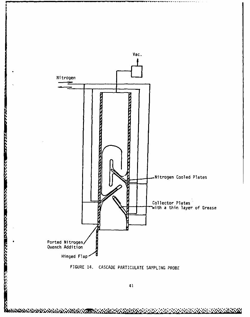
intensifying microexplosion, a sampling probe (Figure 14) has been developed
to collect the fragments produced by microexplosion. The probe consists of a
four-stage cascade impactor with vacuum assist and nitrogen cooling. It is
intended to collect the fragments Just after the occurrence of microexplosion
but without further burning of the carbon particles. Thus, the probe is
positioned one inch above the state of the microexplosion. Nitrogen is
introduced from the walls at the bottom of the probe to cool the incoming gas
as well as to quench the carbon particles. A vacuum at the top of the probeis adjusted to pull the particles up through the probe; the pull is optimizedI: such that the particles do not break up upon contacting the cascades.
* 38
Glass Nozzle
Transducer
FIGURE 12. SCHEMATIC OF DIAPHRAGM-BASED DROPLETGENERATOR FOR SLURRY FUELS
39
... ... ... ~~ J~ 1s
L1)
0 I-
CL 0CiC)
o V) C-cC
E WmiUL
EuE
C-)I-
LAJ
-
E 0 CD(A CL
S-J -J
SU-
LJ
U-
Im-
U--
EO40
Vac.
Nitrogen
-Nitrogen Cooled Plates
Collector Plates- - with a thin layer of Grease
* Ported Nitrogen
Quench Addition
Hinged Flap
FIGURE 14. CASCADE PARTICULATE SAMPLING PROBE
41
The cascades consist of brass collector plates covered by a layer
of high-vacuum grease and attached to nitrogen-cooled hangers. We found that
a sampling time of 15 to 20 seconds was optimum to collect sufficient sample
for analysis without burning the covering grease.
Design and arrangement decisions as discussed above were all based
on the criterion of counting particles larger than 51jm.
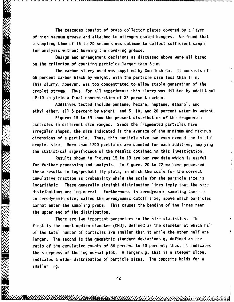
The carbon slurry used was supplied by Sun Tech Co. It consists of
56 percent carbon black by weight, with the particle size less than lu m.
This slurry, however, was too concentrated to allow stable generation of the
droplet stream. Thus, for all experiments this slurry was diluted by additional
JP-10 to yield a final concentration of 22 percent carbon.
Additives tested include pentane, hexane, heptane, ethanol, and
ethyl ether, all 5 percent by weight, and 5, 10, and 20 percent water by weight.
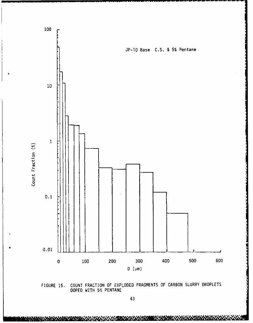
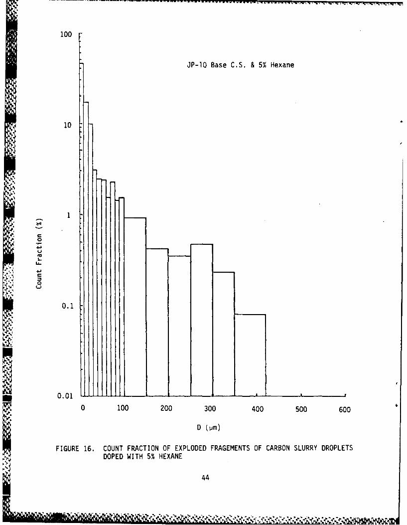
Figures 15 to 19 show the present distribution of the fragmented
particles in different size ranges. Since the fragmented particles have
irregular shapes, the size indicated is the average of the minimum and maximum
dimensions of a particle. Thus, this particle size can even exceed the initial
droplet size. More than 1100 particles are counted for each additive, implying
the statistical significance of the results obtained in this investigation.
Results shown in Figures 15 to 19 are our raw data which is usefulfor further processing and analysis. In Figures 20 to 22 we have processed
these results in log-probability plots, in which the scale for the correct
cumulative fraction is probability while the scale for the particle size is
logarithmic. These generally straight distribution lines imply that the size
distributions are log-normal. Furthermore, in aerodynamic sampling there is
an aerodynamic size, called the aerodynamic cutoff size, above which particles
cannot enter the sampling probe. This causes the bending of the lines near
the upper end of the distribution.There are two important parameters in the size statistics. The
first is the count median diameter (CMD), defined as the diameter at which half
of the total number of particles are smaller than it while the other half are
larger. The second is the geometric standard deviationa g, defined as the
ratio of the cumulative counts of 84 percent to 50 percent; thus, it indicates
the steepness of the log-normal plot. A largera g, that is a steeper slope,
idicates a wider distribution of particle sizes. The opposite holds for a
smaller ag.
42
100
JP-10 Base C.S. & 5% Pentane
41
10
4-)
0.1
0.01
0 100 200 300 400 500 600
FIGURE 15. COUNT FRACTION OF EXPLODED FRAGMENTS OF CARBON SLURRY DROPLETS
DOPED WITH 5% PENTANE
43
100
JP-1O Base C.S. & 5% Hexane
10
0
1..
C
0
0.1
I~i
0,01 L L_,_,
0 100 200 300 400 500 600
D (6m)
FIGURE 16. COUNT FRACTION OF EXPLODED FRAGEMENTS OF CARBON SLURRY DROPLETS
DOPED WITH 5% HEXANE
44
100
JP-10 Base C.S. & 5% Heptane
10
01
0.01
0 100 200 300 400 500 600
FIGURE 17. COUNT FRACTION OF EXPLODED FRAGEMENTS OF CARBON SLURRY DROPLETSDOPED WITH 5% HEPTANE
45
100
JP-10 Base C.S. & 5% Ethanol
10
0.
U -l
4~46
Ct tAL
100
JP-lO Base C.S. & 5% Ethyl Ether
10
1
0
D um
- 0.1
FIGURE 19. COUNT FRACTION OF EXPLODED FRAGMENTS OF CARBON SLURRY DROPLETS
WITH 5% ETHYL ETHER
47
1000 08 C?4D
* C.S. + 5% Pentane 6.30 10
A C .S. + 5% Hexane 7.63 9.6
* C.S. + 5% Heptane 7.69 7.8D
100
74.6360 -
10I
11 f I I I
F T
FIGURE 20. COUNT CUMULATIVE PLOT FOR CARBON SLURRY DOPED WITH PENTANE, HEXANE,AND HEPTANE
48
1000
CMD
C.S. + 5% Ethanol 3.47 7.2
D A C.S. + 5% Ethyl Ether 5.81 8.6
100
A
50 __
25I
7.2 - - - - -
2 103I070 8 o9
Con CuuaieFatoIFIGURE~~~ ~ ~ ~ 21ION UUAIEPO O ABO LRYDPDWT TAO N
ETY ETE
49I
1000 G M
*c.s. 4.42 38.5
C,S +5% HID 3.32 22
D A C.S. +10% d20 2.83 21*
G )C.S. +2% H20 2.10 -j.5
17C--
.100
7163
4438.!
2221
101
10 10 30 5I0 8 09
Con CuuaieFatoIFIGRE 2.COUT UMUATVE LOTFO CABO SLRR EMI FIDWT AIU
AMUT OFWAE50I
Recognizing the physical significance of the parameters CMD ando g,
we note that carbon slurry, without additive, has a CMD of 38p m andog -
4.42. However, in the presence of the volatile miscible additives shown in
Figures 20 and 21, the CMD is reduced to values of 7 to lOum. Furthermore,
except for ethanol, the size distributions are now wider. Thus, there is
definite advantage in doping the carbon slurry with small quantities (5 percent)
of the volatile fuels tested herein so as to reduce the size of the agglomerate
fragments.
Tests have also been run with water addition. Since water does not
mix with JP-10, a 2-percent surfactant of Span 80 and Tween 85 was used for
emulsification. Figure 18 shows that with water emulsification CMD is reduced,
although not to the extent obtained with the volatile miscible fuels. The
CMD is also not sensitive to the amount of water addition. The size
distributions are narrower here.
The results with water emulsification is somewhat surprising because
initially we had expected that it could be more efficient in rupturing the
agglomerate. We believe that this is caused by the action of the emulsifying
surfactants which have high boiling points and are very viscous. This promotes
gluing of the particles, and thereby larger fragments and narrower
distributions.
Finally, we note that the surfactants used in stabilizing the slurry
fuel obviously also play a role in inducing microexplosion. That is, since
microexplosion is not expected to occur for a mixture of only JP-10 and carbon
powder, the fact that the slurry droplets do microexplode implies that their
presence is essential in this phenomenon.
51
2. Volatile Additive Conclusions
The following conclusions can be drawn from the present study.
1. The carbon slurry fuel can microexplode without any additive, possibly
due to the surfactants used for stabilization.
2. Addition of 5 percent volatile fuels which are also miscible with the
slurry fuel, can significantly reduce the average size of the agglomerate
fragments. Boiling points of these additive fuels should be less than
100 C, corresponding to that of heptane.
3. Water emulsification is not as effective in rupturing the agglomerate,
possibly due to the presence of the emulsifying agents used.
3. Volatile Additive Recommendations
Perform and compare some test runs with (a) existing carbon slurry
and (b) existing carbon slurry doped with 5 percent heptane or any other fuel
of equal or higher volatility.
V. ACKNOWLEDGMENTS
The assistance of Warren Nicholson and Dr. Harold Epstein in designing
the apparatus for the CW and pulse laser experiments was much appreciated.
52
REFERECE
(1) Ivanov, V. M., Kantorovich, B. V., Rapiovets, L. S., and Khotuntsev,L. L., "Fuel Emulsions for Combustion and Gasification," Jour. Acad. Sci.,U.S.S.R., May 1957, pp 56-59.
(2) Ivanov, V. M., and Nefedov, P. I., "Experimental Investigation of theCombustion Process on Natural and Emulsified Fuels," NASA Tech. Transl.TT F-258, January 1965, 23 pp.
(3) Ludera, L., "Water Emulsions of Boiler Fuel Oils and Possibilities ofUsing Them as Liquid Fuels," Gospodarka Paliwami i Energia, Vol. 1, 1965,pp 5-9.
(4) Law, C. K., Law, H. K., and Lee, C. H., "Combustion Characteristics ofDroplets of Coal/Oil and Coal/Oil/Water Mixtures," Energy A, 329-339(1979).
(5) Yap, L. T., Kennedy, I. M., and Dryer, F. L., "Disruptie and MicroexplosiveCombustion of Free Droplets in Highly Convective Environments," Comb Sciand Tech 41, 291-313 (1984).
(6) Lasheras, J. C., Fernandez-Pello, A. C., and Dryer, F. L., "ExperimentalObservations on the Disruptive Combustion of free Droplets ofMulticomponent Fuels," Comb Sci and Tech 22, 195-209 (1980).
(7) Kramllch, J. C., Seeker, W. R. and Payne, R., Topical Report to U. S.Dept. of Energy from Energy and Environmental Research Corp. on ContractNo. DE-AC22-80PC30298, 1982.
(8) Gallahalli, S. R., Combustion Science and Technology, 1979, V19, 245-250.
(9) Law, C. K., AICHE Journal 24(4), 626-632 (1978).
(10) Law, C. K., Progress in Energy and Combustion Science, 8(3),169-199(1982).
(11) Wang, C. H., and Law, C. K., Combustion and Flame, 59:53-62(1985).
(12) Wang, C. H., Liu, X.Q., and Law, C. K., Combustion and Flame, 56:175-197(1984).
(13) Law, C. K., Law, H. K., and Lee, C. H., Energy, A 329-339(1979).
(14) Saito, M., Sadakata, M. and Sakai, T., Fuel, 62 (12), 1981(1983).
53
(Continued)
(15) Sakai, T., Masayoshi, S. and Saito, M., Fuel, 64 (2), 163(1985).
(16) Gray, P., and Yoffee, A. 0., Proceedings Royal Society, 200A, 114(1949).
(17) Olen, K. R., Chemically Enhanced Combustion of Water-Slurry Fuels, U.S.Patent 4,455,150, issued June 19, 1984.
(18) Karn, F. S., and Sharkey, A. G., Fuel, Lond. 4Z 193(1968).
(19) Karn, F. S. and Singer, J. M., Fuel, Lond. 4 235 (1968).
(20) Lee, J. H. and Knystautas, R., Paper No. 68-146, A.I.A.A., Sixth AerospaceSciences Meeting, New York (1968).
(21) Lee, J. H., Akineete, V. A., Knystautas, R. and Habashi, W., TwelfthSymposium (International) on Combustion, Comb. Inst., Pittsburgh (1969).
(22) Schwar, M.J.R. and Weinberg, F. J., Comb. and Flame (13), p 335 (1969).
(23) Ballantyne, A., Chou, H., Nedh, K., Oroczo, N. and Stickler, D., ACS FuelDivision Preprints, 29(2), 119-128(1984).
(24) Sinha, M. P., Rev. Sct. Instrum. 55(6), 886-891 (1984).
(25) Weinberg, F. J. and Wilson, J. R., Proc. Roy. Soc. Lond., A. 321,41-52 (1971).
(26) Ubhayakai, S. K. and Williams, F. A., J. Electrochem Soc., 123(5),747-756(1976).
(27) Turns, S. R., Riddle, S. P. and Faeth, G. M., Final Report fromthe Pennsylvania State University to Aero Propulsion Laboratory,Contract F33615-82-2256, Nov., 1983.
(28) Lindner, V., Explosives and Propellants, Encyclopedia of ChemicalTechnology, 1, 561-671, Edited by Kirk Othmer, 3rd Edition,N.Y., 1980.
(29) Walters, Arden, private communication.
(30) Robertson, A.J.B., "The Thermal Initiation of Explosion in LiquidExplosives," Third Symposium (International) on Combustion,The Williams & Wilkins Co., 1949, Baltimore, MD, p. 545.
54
U.S.Govenment Printing Olffce: 1986 - 748-061/60534
- - - - - - - - - - - - -
IS