Embed Size (px)
Citation preview
I Issued: January 10, 1970
Second Quarterly Report Study to Determine and Improve Design for Lithium-Doped Solar Cells
Prepared for Jet Propulsion Laboratory California Institute of Technology Pasadena, California In fulfillment of Contract No. 952555 October 1 to December 30, 1969 Prepared by G. Brucker, T. Faith J. Corra, and A. Holmes-Siedle
E
RCA Corporation I Defense Electronic Products Astro Electronics Division I Princeton, New Jersey
https://ntrs.nasa.gov/search.jsp?R=19700009282 2018-07-30T01:52:04+00:00Z
AED R-3528 , Issued: January 10, 1970
Second Quarterly Report Study to Determine and Improve Design for Lithium-Doped Solar Cells
Prepared for Jet Propulsion Laboratory California Institute of Technology Pasadena, California In fulfillment of Contract No. 952555 October 1 to December 30, 1969 Prepared by G. Brucker, T. Faith J. Corra, and A. Holmes-Siedle
RCA Corporation I Defense Electronic Products Astro Electronics Division I Princeton, New Jersey
PREFACE
This is the Second Quarterly Report on a program for a I'Study to Determine and Improve Design for Lithium-Doped Solar Cells, Contract No. 952555 for Jet Propulsion Laboratory, Pasadena, California, by the Astro-Electronics Division of RCA, Princeton, New Jersey. The prepara- tion of this report is a contractual requirement covering the period from October 1 to December 30, 1969. The work reported here was conducted by the Radia- tion Effects group, Manager, Dr. A. G. Holmes-Siedle. This group is a part of the Technology Development group, Manager, Mr . Martin Wolf, of the Astro- Electronics Division which is located at the RCA Space Center. The Project Supervisor is Dr. A. G. Holmes-Siedle and the Project Scientist is Dr. G. J. Brucker. The Technical Monitor of the program is Mr. Paul Berman of the Solar Power group, Jet Propulsion Laboratory.
This report was prepared under
ii
ABSTRACT
This is the Second Quarterly Report on a program to study and analyze the action of lithium in producing a recovery of radiation damage in bulk silicon and silicon solar cells, AED of RCA for JPL on Contract No. 952249. The eventual goal of this effort is to understand the damage and recovery mechanisms so that an optimum set of design rules can be specified.
This program has technical continuity with the work performed by
The test vehicles used for this work are (1) a group of solar cells supplied by JPL, and (2) silicon bars in the ItHall-baPt configuration. The source of parti- cle irradiation being used is a 1-MeV electron beam produced by the RCA Lab- oratories Van de Graaff generator.
Progress on solar cell experiments on the cold finger has included continuation of minority-carrier lifetime vs temperature measurements on crucible-grown cells, and anneals at 380'K. Lifetime vs temperature measurements after irradiation on Li-containing cells and non-lithium cells give recombination- center energy-levels at %Ec - 0.20eV, near the level of the A-center. The recovery in an antimony-containing non-lithium cell is more than an order of magnitude larger than expected on the basis of published recovery rates. The recovery of antimony-doped, lithium-containing cells is much lower than expected, suggesting some special interactions of lithium in at least one type of antimony-doped silicon.
Long-term stability tests on lithium-containing crucible-grown cells and float- zone and Lopex cells have continued. Crucible-grown cells are stable for a wide range of densities in tests ranging from 110 days to 379 days after i r ra - diation. Most float-zone and Lopex cells suffer significant post-recovery redegradation within % l o 0 days of irradiation. The time after irradiation at which redegradation sets in is longer for lightly Li-doped cells than for heavily Li-doped cells.
Hall and resistivity measurements on float-zone silicon which show that, as the lithium concentration in the Hall samples decreases, the curve of carrier- removal rate versus temperature appears to shift along the temperature axis to lower temperatures while Itsaturatedtt carrier-removal rates (rates at higher bombardment temperature TB = 140°K - 297°K) appear to decrease. This decrease amounted to a factor of 3 as the resistivity for Hall samples was increased from 0.3 ohm-cm to 10 ohm-cm. The overall behavior in float-zone silicon is similar, but not identical, to that in phosphorus-doped silicon. Evi- dence was obtained which indicates that dissociation of the LiV defect and the formation of complexes between lithium and acceptor defects during the anneal- ing of irradiated Hall samples at 297'K are inhibited by the lack of lithium as the concentration of lithium is reduced to 5 x 10¹⁴ Li/cm3 ( P = 1 0 Q-cm). This may constitute the lower limit of doping density at which the beneficial interaction of lithium can take place for heavily-irradiated cells, -
iii
In a new extension of junction capacitance studies, the diffusion constant and activation energy of lithium near the p-n junction of a cell made from float-zone silicon has been measured over the temperature range -20°C to +40"C. At 4.3 pm from the junction, the diffusion constant and activation energy are nearly representative of those of free lithium. However, at 2.3 pm from the junction the diffusion constant and activation energy are lower than the corres- ponding free lithium values. Thus, classical models of lithium diffusion must be used with caution when analyzing p/n silicon structures.
iv
CONTENTS
Section Page
I INTRODUCTION ............................ 1
A . GENERAL ............................. 1
B . TECHNICALAPPROACH ................... 1
C . SUMMARY O F PREVIOUS WORK .............. 1
I1 LONG-TERM PERFORMANCE O F JPL-FURNISHED CELLS .................................. 3
A . GENERAL ............................. 3
B . CELLS OF SHIPMENTS NO . 1 . 2 . AND 3 ......... 3
C . CELLS O F SHIPMENTS NO. 4 AND 5 ., o . . 6
D . CELLS O F SHIPMENT.NO. 6 ................ 11
E . C E L L STABILITY AND OPTIMUM DESIGN ....... 1 4
1 . Initial Pe r fo rmance .................... 1 8 2 . Recovery ........................... 1 8 3 . Stability ............................ 1 9
I11
IV
SOLAR CELL EXPERIMENTS ON THE COLD FINGER .................................. 20
A . GENERAL ............................. 20
B . LIFETIME VS TEMPERATURE AND ANNEALING MEASUREMENTS ........................ 20
C . DAMAGE CONSTANT VS BOMBARDMENT TEMPERATURE ......................... 25
HALL AND RESISTIVITY MEASUREMENTS e e e e 29
A . INTRODUCTION ......................... 29
B . TEMPERATURE DEPENDENCE O F CARRIER- REMOVALRATE ......................... 29
V
Section
V
VI
CONTENTS (Continued)
Page
C. ANNEALING A T ROOM TEMPERATURE . 31
31 33
1. C a r r i e r Density Changes . . . . . . . . . . . . . . 2. Mobility Changes . . . . . . . . . . . . . . . . . . .
3 4 D. DISCUSSION O F RESULTS AND SUMMARY . . . . . 36 DIFFUSION-CONSTANT MEASUREMENTS . . . . . . . . .
A. GENERAL ........................... 36
36 B. DISCUSSION .......................... 38 CONCLUSIONS AND FUTURE WORK . . . . . . . . . . . . . 38 A. GENERAL ...........................
B. SOLAR C E L L STABILITY . . . . . . . . . . . . . . . . 38
1. Initial Per formance . . . . . . . . . . . . . . . . . . 38 2. R e c o v e r y . , ....................... 38 3. Stability ......................... 39
C. LOW-TEMPERATURE STUDIES ON CELLS 39
40 D. HALLMEASUREMENTS . . . . . . . . . . . . . . . . . E. DIFFUSION CONSTANT MEASUREMENTS . . . . . . 40
F. F U T U R E P L A N S . . . . . . . . . . . . . . . . . . . . . . . 41
41 1. Solar Cel l Studies . . . . . . . . . . . . . . . . . . . 2. Hall Measurements . . . . . . . . . . . . . . . . . . 41 3. Diffusion Constant Measurements ......... 41
REFERENCES 42 ............................
v i
ILLUSTRATIONS
Figure Page
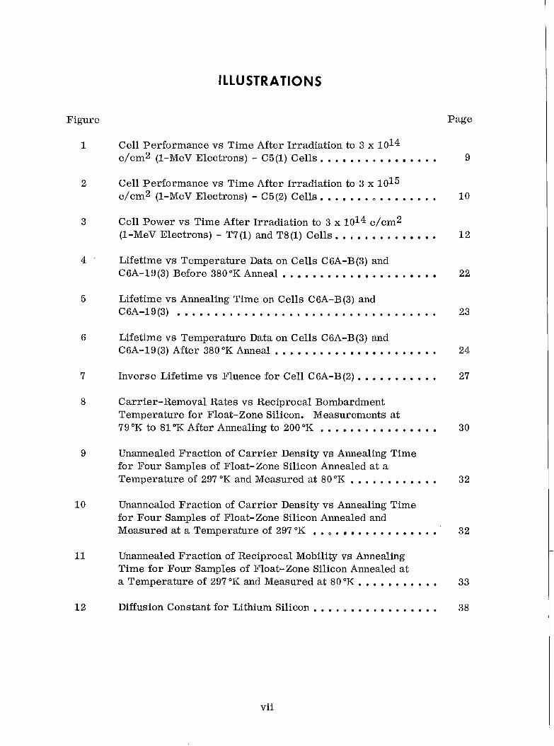
1 Cell Performance vs Time After Irradiation to 3 x 10¹⁴ e/cm2 (1-MeV Electrons) - C5(1) Cells. . . . . . . . . . . . . . 9
2 Cell Performance vs Time After Irradiation to 3 x 10¹⁵ e/cm2 (1-MeV Electrons) - C5(2) Cells. . . . . . . . . . . . . . . 10
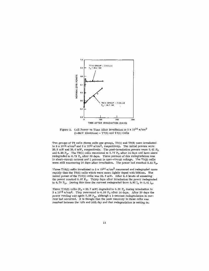
3 Cell Power vs Time After Irradiation to 3 x 10¹⁴ e/cm2 (1-MeV Electrons) - T7(1) and T8(1) Cells. . . . . . . . . . 1 2
4 ' Lifetime vs Temperature Data on Cel ls C6A-B(3) and C6A-19(3) Before 380"KAnneal. , . . . . . . . . . . . . . 22
5 Lifetime vs Annealing Time on Cells C6A-B(3) and C6A-19(3) . . . . . . . . . . . . . . . . . . . . . . . . . . . . . . . . . . . 23
6 Lifetime vs Temperature Data on Cel ls C6A-B(3) and C6A-19(3) After 380°K Anneal . . , . . . . . . . . . . . . , . . . . 24
7 Inverse Lifetime vs Fluence for Cell C6A-B(2). . . . . . , . . . . 27
8 Carrier-Removal Rates vs Reciprocal Bombardment Temperature for Float-Zone Silicon. Measurements at 79 "K to 81 "K After Annealing to 200 "K . . . . , . , . . . . . . . . . 30
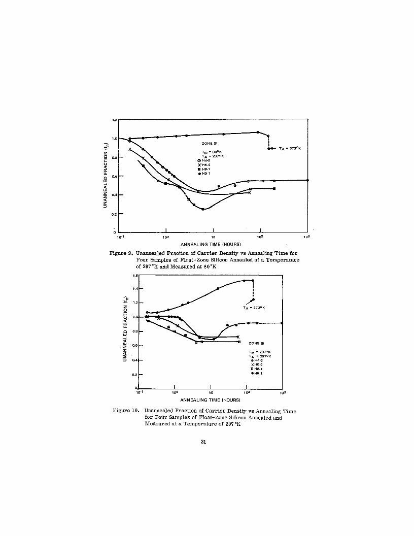
9 Unannealed Fraction of Carrier Density vs Annealing Time for Four Samples of Float-Zone Silicon Annealed at a Temperature of 297 "K and Measured at 80°K . . . , . . , . . . . . 32
10
11
1 2
Unannealed Fraction of Carrier Density vs Annealing Time for Four Samples of Float-Zone Silicon Annealed and Measured at a Temperature of 297°K , . ., . . . . . . . . . . . . 32
Unannealed Fraction of Reciprocal Mobility vs Annealing Time for Four Samples of Float-Zone Silicon Annealed at a Temperature of 297 "K and Measured at 80 "K . . . . . . . . . . . 33
Diffusion Constant for Lithium Silicon . . . . ,, . . . . . . . . . . . . 38
vii
TABLES
Table Page
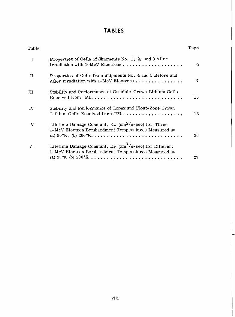
I Properties of Cells of Shipments No. 1, 2, and 3 After Irradiation with 1-MeV Electrons ................... 4
I1
111
IV
V
VI
Properties of Cells from Shipments No. 4 and 5 Before and After Irradiation with 1-MeV Electrons ............... 7
Stability and Performance of Crucible-Grown Lithium Cells Received from JPL. . ........................... 15
Stability and Performance of Lopex and Float- Zone Grown Lithium Cells Received from JPL ................... 1 6
Lifetime Damage Constant, K ,. (cm2/e-sec) for Three 1-MeV Electron Bombardment Temperatures Measured at (a) 90°K, (b) 200°K. ............................ 26
Lifetime Damage Constant, Kr (cm /e-sec) for Different 1-MeV Electron Bombardment Temperatures Measured at (a) 90°K (b) 200°K .............................
2
27
viii
SECTION I
I NTRODUCTI 0 N
A. GENERAL
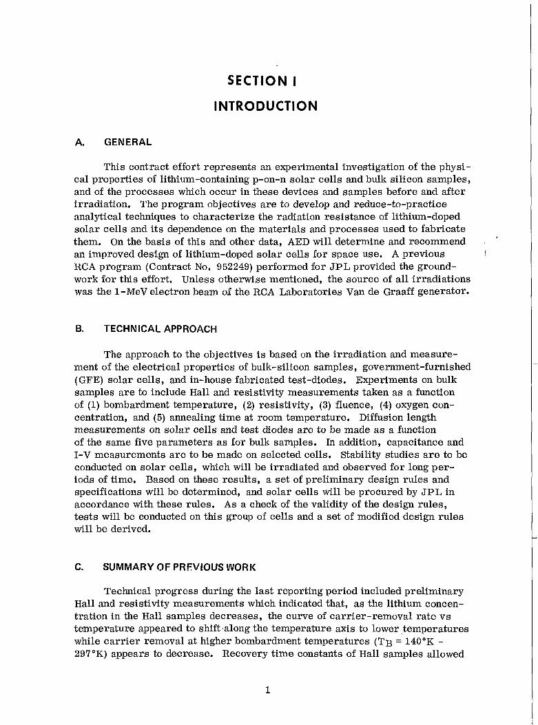
This contract effort represents an experimental investigation of the physi- cal properties of lithium-containing p-on-n solar cells and bulk silicon samples, and of the processes which occur in these devices and samples before and after irradiation. The program objectives are to develop and reduce-to-practice analytical techniques to characterize the radiation resistance of lithium-doped solar cells and its dependence on the materials and processes used to fabricate them. On the basis of this and other data, AED will determine and recommend an improved design of lithium-doped solar cells for space use. A previous RCA program (Contract No. 952249) performed for JPL provided the ground- work for this effort, Unless otherwise mentioned, the source of all irradiations was the 1-MeV electron beam of the RCA Laboratories Van de Graaff generator.
B. TECHNICAL APPROACH
The approach to the objectives is based on the irradiation and measure- ment of the electrical properties of bulk-silicon samples, government-furnished (GFE) solar cells, and in-house fabricated test-diodes. Experiments on bulk samples are to include Hall and resistivity measurements taken as a function of (1) bombardment temperature, (2) resistivity, (3) fluence, (4) oxygen con- centration, and (5) annealing time at room temperature. Diffusion length measurements on solar cells and test diodes are to be made as a function of the same five parameters as for bulk samples. In addition, capacitance and I-V measurements a re to be made on selected cells. Stability studies a re to be conducted on solar cells, which will be irradiated and observed for long per- iods of time. Based on these results, a set of preliminary design rules and specifications will be determined, and solar cells will be procured by JPL in accordance with these rules. As a check of the validity of the design rules, tests will be conducted on this group of cells and a set of modified design rules will be derived.
C. SUMMARY OF PREVIOUS WORK
Technical progress during the last reporting period included preliminary Hall and resistivity measurements which indicated that, as the lithium concen- tration in the Hall samples decreases, the curve of carrier-removal rate vs temperature appeared to shift along the temperature axis to lower temperatures while carrier removal at higher bombardment temperatures (TB = 140°K - 297'K) appears to decrease. Recovery time constants of Hall samples allowed
1
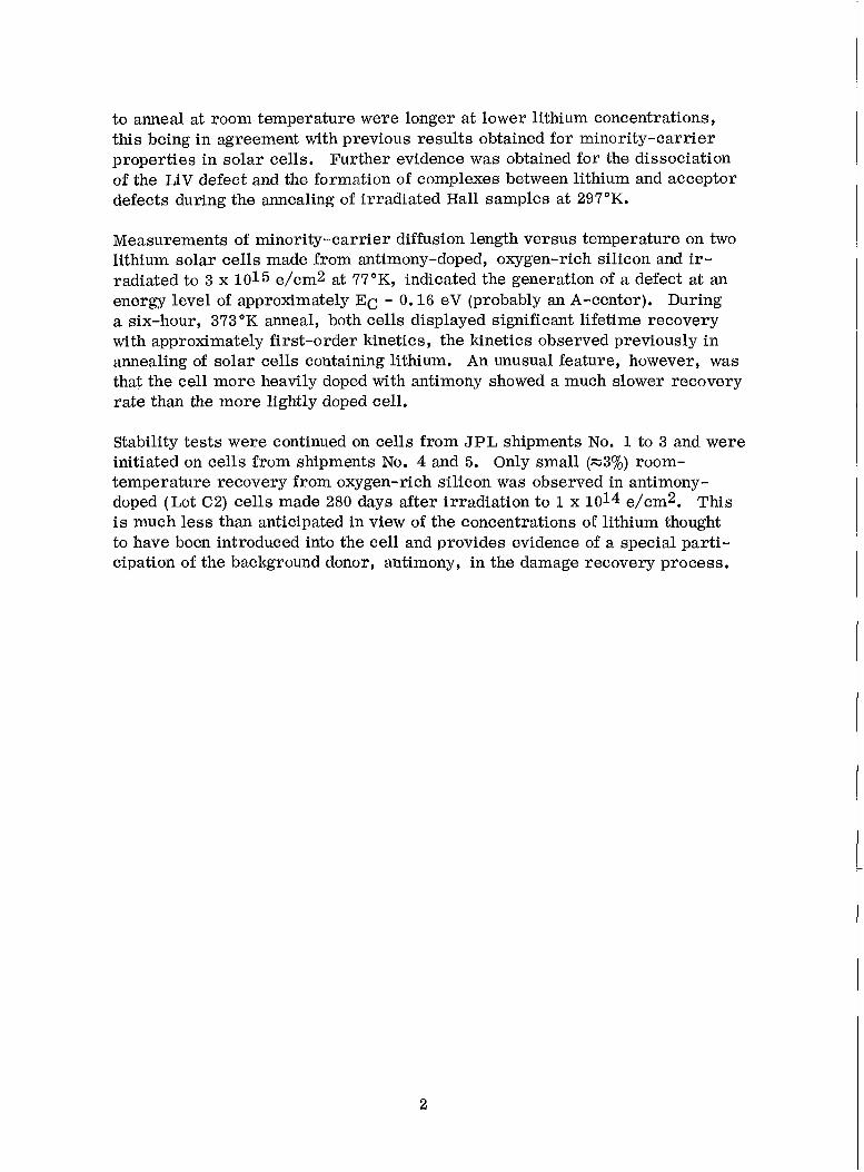
to anneal at room temperature were longer at lower lithium concentrations, this being in agreement with previous results obtained for minority-carrier properties in solar cells. Further evidence was obtained for the dissociation of the LiV defect and the formation of complexes between lithium and acceptor defects during the annealing of irradiated Hall samples at 297°K.
Measurements of minority-carrier diffusion length versus temperature on two lithium solar cells made from antimony-doped, oxygen-rich silicon and ir- radiated to 3 x 10¹⁵ e/cm2 at 77"K, indicated the generation of a defect at an energy level of approximately EC - 0.16 eV (probably an A-center). During a six-hour, 373 "K anneal, both cells displayed significant lifetime recovery with approximately first-order kinetics, the kinetics observed previously in annealing of solar cells containing lithium. An unusual feature, however, was that the cell more heavily doped with antimony showed a much slower recovery rate than the more lightly doped cell.
Stability tests were continued on cells from JPL shipments No. 1 to 3 and were initiated on cells from shipments No. 4 and 5. Only small (=30/0) room- temperature recovery from oxygen-rich silicon was observed in antimony- doped (Lot C2) cells made 280 days after irradiation to l x 1014 e/cm2. This is much less than anticipated in view of the concentrations of lithium thought to have been introduced into the cell and provides evidence of a special parti- cipation of the background donor, antimony, in the damage recovery process.
2
SECTION II
LONG-TERM PERFORMANCE OF JPL-FURNISHED CELLS
A. GENERAL
In the previous contract, 5 shipments of lithium cells were received from JPL. The cells were manufactured by T. I. , (T), Heliotek, (H) and Centralab (C) from a wide variety of silicon stock with varying lithium introduction condi- tions. Several competitive 10 ohm-cm n/p commercial solar cells were sup- plied for comparison purposes. Investigation of these cells has been carried over into the present contract. Tests performed on the cells included measure- ments of photovoltaic I-V characteristic under Tungsten illumination, p/n junction characteristics in the dark, reverse-bias capacitance characteristics, and minority-carrier diffusion length in the base region. Tungsten I-V charac- teristics were measured with a power density of 140 mW/cm2 incident on the cell surface. Cell temperature was maintained at 28°C by water and forced- air cooling, These measurements have long term reproducibility of approxi- mately 2 percent. In addition to the measurements at 140 mW/cm2, compara- tive I-V characteristics were frequently taken at a number of light levels to provide information on cell series resistance and junction properties (Ref. 1). During the previous year, cells of shipments No. 1, 2, and 3 had been irradiat- ed at room temperature by 1-MeV electrons to one of three fluences:" 1 x 10¹⁴ e/cm2, 5 x 10¹⁴ e/cm2, o r 3 x 10¹⁵ e/cm2. At the start of the present re- porting period, cells from shipments No. 4 and 5 were irradiated to one of two fluences: 3 x 10¹⁴ e/cm2 o r 3 x 10¹⁵ e/cm2. In the case of shipments No. 3, 4, and 5 several cells were left unirradiated for other experiments and to test the stability of unirradiated lithium cells,
Shipments No. 1, 2, and 3 cells which have a much longer post-irradiation history than shipment 4 and 5 cells (Ref, 2 and 3) will be discussed in part B of this section. Cells from shipments No, 4 and 5 will be discussed in part C. A new set of cells, shipment No. 6, received during the present contract year will be discussed in part D. This will be followed in part E, with a discussion of all the stability results to date on the JPL-furnished cells together with some conclusions regarding optimum cell design.
5. CELLS OF SHIPMENTS NO. 1,2, AND 3
Table I gives post-irradiation performance figures for the cell groups of shipments No. 1, 2, and 3. The first column gives the cell group code, where the letter identifies the manufacturer, the first number gives the cell lot, and
*In one of the irradiations, due to an error, cells were exposed to ~ 8 x 1 0 ~ ~ e/cm2 of a 0 , 7 MeV electrons instead of the intended 5x10¹⁴ e/cm2 of 1-MeV electrons.
3
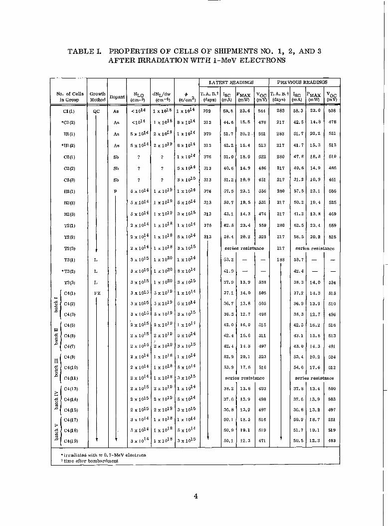
TABLE I. PROPERTIES O F CELLS OF SHIPMENTS NO. 1, 2, AND 3 AFTER BRADIATION WITH 1-MeV ELECTRONS
ser ies resistance
MAX mw)
23.4
15.5
20.2.
15.4
18.9
14.9
10.9
23.1
19.5
14.3
23.4
20.2
dNI/dw (cm-4)
1 x 10¹⁸
1 x 10¹⁸
2 1019
2 1019
?
?
?
1 1019
1 1019
1 1019
1 x 10¹⁸
1 x 10¹⁸
1 x 10¹⁸
1 x 10²⁰
1 x 10²⁰
1 x 10²⁰
5 1019
5 1019
5 1019
2 1019
2 1019
2 1019
1 x 10¹⁸
1 x 10¹⁸
1 x 10¹⁸
2 1019
2 1019
2 1019
1 x 10¹⁸
1 x 10¹⁸
1 x l 0 1 8
r
voc (mv)
544
478
551
513
522
486
451
556
531
474
559
525
LATEST READINGS
ser ies
- . A . B.1 (days) - - 379
31 3
379
313
376
31 3
31 3
376
313
313
376
resis
- Isc mA)
59.8
44.6
51.7
42.2
51.0
40.6
31.2
57.5
50.7
43.1
62.5
58.4
- -
P
t
188
t
53.2
41.9
37.9
37.1
36.7
36.3
42.0
42.4
42.4
52.9
53.9
FZ
V
-
-
13.9
14.0
13.8
12.7
16.0
15.6
14. 3
20.1
17. 6
- -
538
505
505
496
51 5
511
497
52 3
51 6
ser ies resistance
PREVIOUS READINGS - I s c m A) - - 58.3
42.5
51.7
41.7
47.8
40.6
31.2
57.5
50.2
41.2
62.5
58.5
- MAX :mw) - - 23.0
14.8
20.2
15.3
18.8
14.9
10.9
23.1
19.4
13.8
23.4
20.2
53.7
42.4
38.3
37.2
36.9
36.3
42.5
43.1
43.0
53.4
54.6
-
-
14.0
14.3
13.9
12.7
16.2
15.8
14.3
20.2
17.6
- "oc [my
538
478
551
513
51 9
486
451
556
525
469
559
525
- -
nce
- -
534
51 5
510
496
51 6
51 3
491
524
51 2
series resistance
'irradiated with = 0.7-MeV electrons t time after bombardment
4
the number in parenthesis gives the cell group within a given lot, The second and third columns give the silicon growth method (quartz-crucible, Lopex, o r float-zone) and n-type base dopant, respectively. The fourth and fifth columns give the donor density at the edge of the depletion region and the donor density gradient, both obtained from pre-irradiation capacitance-voltage measure- ments. The sixth column gives the electron fluence experienced by the cells. The seventh through tenth columns give the elapsed time after irradiation, averaged short-circuit current, power, and open-circuit voltage, respectively, as of the most recent reading. The eleventh through fourteenth columns give similar values for the previous reading. Individual cell groups will be dis- cus sed briefly.
The average initial (pre-irradiation) output for C1 cells was 30.6 mW which was higher than the 28.1 mW for n/p control cells. During irradiation to 1 x 10¹⁴ e/cm2, Cl(1) cells degraded in performance to P = 18.6 mW. These cells continue to experience slow recovery. As of the most recent set of readings, 379 days after irradiation, the power of Cl (1) cells was 23.4 mW, approximately 9 percent above the 21.4 mW averaged power for four n/p cells obtained after irradiation to 1 x 10¹⁴ e/cm2. Cells of group Cl(2) degraded to P = 13.8 mW during irradiation to a fluence of X 8 x 10¹⁴ e/cm2 of ~0.7-MeV electrons. No significant recovery occurred during the first 76 days after irradiation; however, as of the 217th day the cells recovered to a power of 14.8 mW, and to 14.9 mW after 313 days, a value which is 10 percent below the 16.5 mW for n/p cells experiencing the same irradiation. The slow re- covery in C1 cells is attributed to the low lithium density in these cells and to the high oxygen content of the cells (which has been found to lower the lithium diffusion constant in QC cells to a factor of -1000 below that in F Z cells). It appears that the recovery cycle for these cells is almost complete. If this is the case the lightly irradiated C1 cells are competitive with n/p cells but the more heavily irradiated ones a r e not.
The QC grown, but more heavily doped H1 cells had low initial power, 20.7 mW. Group Hl(1) cell recovery has evidently saturated at 20.2 mW. Group Hl(2) cells show only small additional recovery between 217 days and 313 days after irradiation to a power of 15.4 mW, approximately 7 percent below the n/p level.
Cells of Lot C2, which were made from antimony-doped silicon (QC) presented a puzzle in that no recovery had occurred as much as 139 days after irradiation. However, the two most recent measurements show small but significant re- covery in one of the three groups; C2(1). Three hundred and seventy-six days after irradiation these cells, irradiated to 1 xxOi4 e/cm2, recovered in power from 17.9 to 18.9 mW. Three hundred and thirteen days after irradiation, groups C2(2) and C2(3) have not yet shown recovery.
The cells of group H2(1) had reasonably good initial performance (Po = 26.0 mW). The recovery saturated sixty-nine days after irradiation, giving the
H2(1) cells an averaged power of 22.9 mW, 7 percent above the average of two 10-ohm-cm n/p cells irradiated to the same fluence. The cells have been stable since that time. The cells of group H2(2) had initial power of 24.3 mW; the H2(3) cells, 25.2 mW. Both groups continue to recover with H2(2) cells being 11 percent higher and H2(3) cells 4 percent higher in power than their respective n/p control cells. The power of the H2(2) cells is evidently level- ing off, i. e., recovery has almost been completed.
The T2(1) and T2(2) cells, which had shown suspiciously fast recovery (Ref. 2) for QC grown cells have been stable since the completion of recovery except for a xl percent drop in ISC. They are superior in power output to their control cells by 1 0 percent and 14 percent, respectively. Cells of group T2(3) developed high series resistance after heavy irradiation to 3 x 10¹⁵ e/cm2. This has been a problem encountered consistently by heavily irradiated lithium cells with a low level of base doping.
Only short-circuit current measurements are available for T3(1) and T3(2) cells. Since peak recovery ( ~ 3 days after irradiation), these cell groups have suffered 7 percent and 8 percent redegradation, respectively, in short- circuit current. Cells of group T3(3) also have suffered significant current redegradation of M 6 percent. Current redegradation continues in the T3- cells although at a reduced rate ( -1 percent per 200 days) compared to that suffered from -10 to 40 days after irradiation ( ~ 1 percent per 10 days).
Cells of lot C4 came in 5 batches, indicated in Table I, the lithium diffusion schedule varying from batch to batch. Given in order of decreasing lithium density, the highest density first, they are: I, IV, 11, V, III. Table I indicates that cells of all batches have suffered redegradation in short-circuit current ranging up to M 6 percent in groups C4(7), batch I. Similar degradations were observed in all batches of unirradiated C4 cells.
The open-circuit voltage redegradation previously observed (Ref. 3) in the more lightly irradiated groups (1 and 3 x 10¹⁴ e/cm2) of the heavily doped batches of C4 cells (batches I, I1 and IV) has continued. Such degradation was also observed in unirradiated C4 cells.
C. CELLS OF SHIPMENTS NO. 4 AND 5
A total of 150 lithium cells were received in shipments No. 4 and 5. Forty-five of these cells were irradiated to 3 x 10¹⁴ e/cm2 on August 4, 1969, and forty-five were irradiated to 3 x 10¹⁵ e/cm2. The early (first 35 days) post-irradiation history of these cells was discussed in the First Quarterly Report on this work (Ref. 3). The continuation of that history up to and in- cluding 110 days after irradiation is given below. Table I1 gives many proper- ties of the cells from these shipments and also lists their pre- and post- irradiation photovoltaic characteristics. This table then essentially summarizes the behavior of these cells for 110 days following irradiation.
6
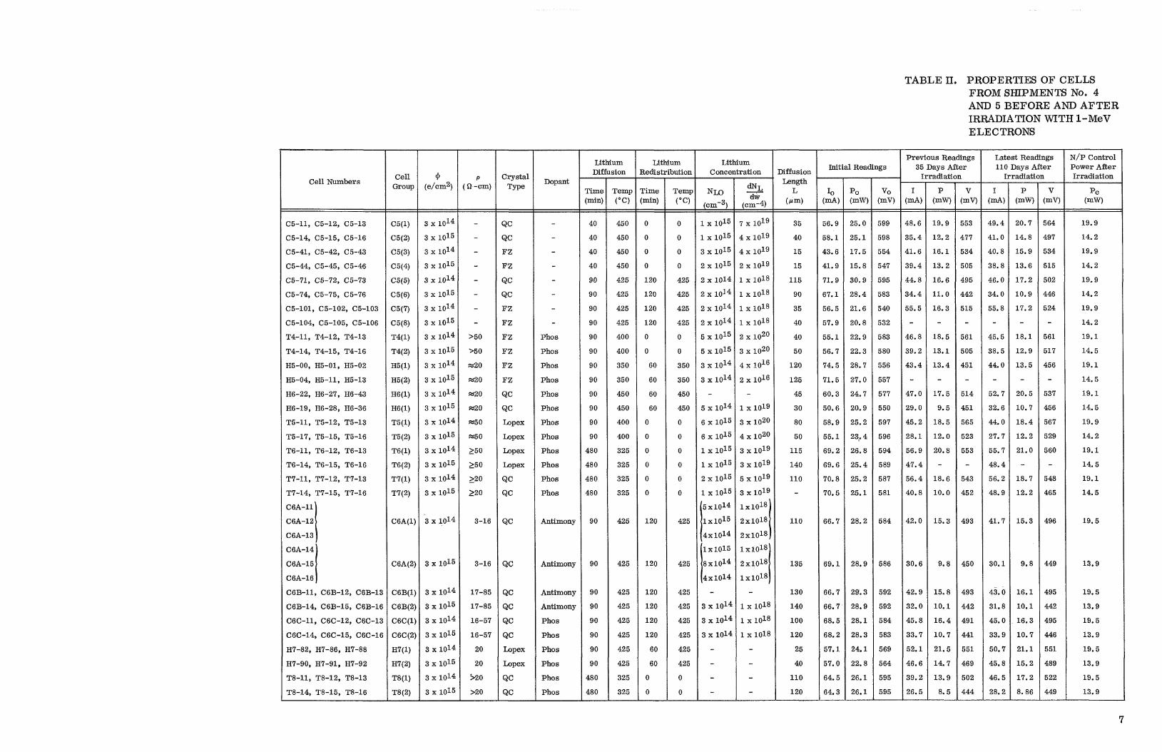
TABLE 11, PROPERTIES OF CELLS FROM SHPMENTS No. 4 AND 5 BEFORE AND AFTER IRRADIATION WITH 1-MeV ELECTRONS
Lithium Diffusion
Lithium ledistribution
Lithium Concentration
N / P Control Power After Irradiation
P C
(mw)
Latest Readings 110 Days After
Irradiation
Previous Readings 35 Days After
Irradiation Initial Readings Xffusion
Length L
(Pm)
35
40
15
15
115
90
35
40
40
50
120
125
45
30
80
50
115
140
110 -
110
135
130
140
100
120
25
40
110
120
crystal Type
QC
QC
F Z
F Z
QC
QC
F Z
F Z
F Z
F Z
F Z
F Z
QC
QC
Lopex
Lopex
Lopex
Lopex
QC
QC
QC
QC
QC
QC
QC
QC
Lopex
Lopex
QC
QC
Cell Numbers P Q.-cm)
- - - - - - - -
>50
,50
a20
a20
a20
W20
W50
W50
- >50
150
- >20
- >20
3-16
3-16
17-85
17-85
16-57
16-57
20
20
520
>20
Dopant
- - - - - - - -
Phos
Phos
Phos
Phos
Phos
Phos
Phos
Phos
Phos
Phos
Phos
Phos
Antimony
Antimony
Antimony
Antimony
Phos
Phos
Phos
Phos
Phos
Phos
rime min) - - 40
40
40
40
90
90
90
90
90
90
90
90
90
90
90
90
$80
$80
$8 0
$80
90
90
90
90
90
90
90
90
480
480 -
remp ("C) - - 45 0
450
45 0
450
425
425
425
425
400
400
350
350
45 0
450
400
400
325
325
325
325
425
425
425
42 5
425
425
425
425
325
325 -
3me min)
0
0
0
0
120
120
120
120
0
0
- -
60
60
60
60
0
0
0
0
0
0
120
120
120
120
120
120
60
60
0
0 __.
Temp ("C) - - 0
0
0
0
425
425
425
425
0
0
350
350
450
450
0
0
0
0
0
0
425
425
425
425
425
425
425
425
0
0 -
PO WW)
25.0
25.1
17.5
15.8
30.9
28.4
21.6
20.8
22.9
22.3
28.7
27.0
24.7
20.9
25.2
23,. 4
26.8
25.4
25.2
25.1
-- -
28.2
28.9
29.3
28.9
28.1
28.3
24.1
22.8
26.1
26.1 _I_
- V
(mv) - - 553
477
534
505
495
442
515
- 561
505
451
-
514
451
565
523
553
- 543
452
493
450
493
442
491
441
551
46 9
502
444 -
- V
(mv) - - 564
49 7
534
515
502
446
524
- 561
517
456
- 537
456
567
529
560
- 548
465
496
449
495
442
495
446
551
489
522
449 -
- I (d) - - 48.6
35.4
41.6
39.4
44.8
34.4
55.5
- 46.8
39.2
43.4
- 47.0
29.0
45.2
28.1
56.9
47.4
56.4
40.8
42.0
30.6
42.9
32.0
45.8
33.7
52.1
46.6
39.2
26.5
- I
- - 49.4
41.0
40.8
38.8
46.0
34.0
55.8
- 45.5
38.5
44.0
- 52.7
32.6
44.0
27.7
55.7
48.4
56.2
48.9
41.7
30.1
43.0
31.8
45.0
33.9
50.7
45.8
46.5
28.2 -
- P
(mW) - - 20.7
14.8
15.9
13.6
17.2
10.9
17.2
- 18.1
12.9
13.5
- 20.5
10.7
18.4
12.2
21.0
- 18.7
12.2
15.3
9.8
16.1
10.1
16.3
10.7
21.1
15.2
17.2
8. 86 -
- P
- - 19.9
12.2
16.1
13.2
16.6
11.0
16.3
-
18.5
13.1
13.4
- 17.5
9.5
18.5
12.0
20.8 -
18.6
10.0
15.3
9.8
15.8
10.1
16.4
10.7
21.5
14.7
13.9
8.5 -
IO
- - 56.9
38.1
43.6
41.9
71.9
67.1
56.5
57.9
55.1
56.7
74.5
71.5
60.3
50.6
58.9
55.1
69.2
69.6
70.8
70.5
66.7
69.1
66.7
66.7
68.5
68.2
57.1
57.0
64.5
64.3 -
v o (mV) - - 599
598
5 54
547
5 95
583
5 40
532
5 83
580
556
557
577
550
597
596
594
589
587
581
5 84
586
592
592
5 84
583
569
564
595
595
19.9
14.2
19.9
14.2
19.9
14.2
19.9
14.2
19.1
14.5
19.1
14.5
19.1
14.5
19.9
14.2
19.1
14.5
19.1
14.5
19.5
13.9
19.5
13.9
19.5
13.9
19.5
13.9
19.5
13.9
C5-11, C5-12, C5-13
C5-14, C5-15, C5-16
C5-41, C5-42, C5-43
C5-44, C5-45, C5-46
C5-71, C5-72, C5-73
C5-74, C5-75, C5-76
C5-101, C5-102, C5-103
C5-104, C5-105, C5-106
T4-11, T4-12, T4-13
T4-14, T4-15, T4-16
H5-00, H5-01, H5-02
H5-04, H5-11, H5-13
H6-22, H6-27, H6-43
H6-19, H6-28, H6-36
T5-11, T5-12, T5-13
T5-17, T5-15, T5-16
T6-11, T6-12, T6-13
T6-14, T6-15, T6-16
T7-11, T7-12, T7-13
T7-14, T7-15, T7-16
C6A-11
C6A-12
C6A-13
C6A-14
C6A-15
C6A-16
C6B-11, C6B-12, C6B-13
C6B-14, C6B-15, C6B-16
C6C-11, C6C-12, C6C-13
C6C-14, C6C-15, C6C-16
H7-82, H7-86, H7-88
H7-90, H7-91, H7-92
T8-11, T8-12, T8-13
T8-14, T8-15, T8-16
I
7
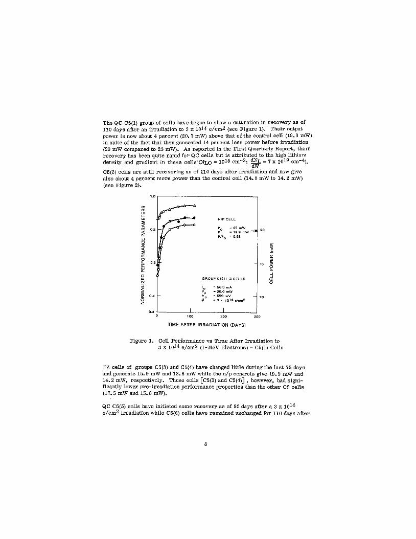
The QC C5(1) group of cells have begun to show a saturation in recovery as of 110 days after an irradiation to 3 x 10¹⁴ e/cm2 (see Figure 1). Their output power is now about 4 percent (20.7 mW) above that of the control cell (19.9 mW) in spite of the fact that they generated 14 percent less power before irradiation (29 mW compared to 25 mW). As reported in the First Quarterly Report, their recovery has been quite rapid for QC cells but is attributed to the high lithium density and gradient in these cells (NLO = 1015 cm-3; = 7 x cm-4).
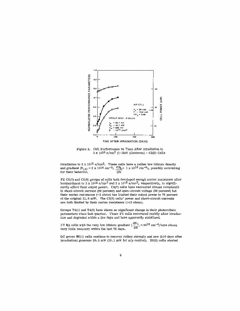
C5(2) cells are still recovering as of 110 days after irradiation and now give also about 4 percent more power than the control cell (14.8 mW to 14.2 mW) (see Figure 2).
dW
1.0 , I
v) K w kl
d I U K
w u z U I K
K w L
9
8 hl
0.8
0.6
0.4
P
NIP CELL
= 29 mW
PIP, = 0.68
GROUP C5(1) -3 CELLS
lo = 56.9 mA Po = 25.0 mW
= 599 mV 2 = 3 x 10¹⁴e/cm2
- K
15
2 -I -I w u I 1 0
0.3 100 200 300
TIME AFTER IRRADIATION (DAYS)
Figure 1. Cell Performance vs Time After Irradiation to 3 x 10¹⁴ e/cm2 (1-MeV Electrons) - C5(1) Cells
FZ cells of groups C5(3) and C5(4) have changed little during the last 75 days and generate 15.9 mW and 13.6 mW while the n/p controls give 19.9 mW and 14.2 mW, respectively. These cells [C5(3) and C5(4)] , however, had signi- ficantly lower pre-irradiation performance properties than the other C5 cells (17.5 mW and 15.8 mW).
QC C5(5) cells have initiated some recovery as of 80 days after a 3 x e/cm2 irradiation while C5(6) cells have remained unchanged for 110 days after
8
20
F E - LT
15
0, -I -1 w 0
ROUP C5I21 - 3 CELLS
Io = 58.1 mA Po = 25.1 mW 10
100 300
TIME AFTER IRRADIATION (DAYS)
Figure 2. Cell Performance vs Time After Irradiation to 3 x 10¹⁵ e/cm2 (1-MeV Electrons) - C5(2) Cells
irradiation to 3 x 10¹⁵ e/cm2. These cells have a rather low lithium density and gradient (NLO = 2 x 1014 cm-3; %= 1 x 10l8 cmm4), possibly accounting for their behavior. dW
FZ C5(7) and C5(8) groups of cells both developed enough series resistance after bombardment to 3 x 10¹⁴ e/cm2 and 3 x 10¹⁵ e/cm2, respectively, to signifi- cantly affect their output power. C5(7) cells have recovered almost completely in short-circuit current (99 percent) and open-circuit voltage (96 percent) but their series resistance (-2 ohms) has limited their output power to 79 percent of the original 21.6 mW. The C5(8) cells' power and short-circuit currents are both limited by their series resistance (>lo ohms).
Groups T4(1) and T4(2) have shown no significant change in their photovoltaic parameters since last quarter. These F Z cells recovered rapidly after irradia- tion and depaded within a few days and have apparently stabilized.
FZ H5 cells with the very low lithium gradient ( %< 1OI8 cm-4) have shown very little recovery within the last 75 days.
QC grown H6(1) cells continue to recover rather strongly and now (110 days after irradiation) generate 20.5 mW (19.1 mW for n/p control). H6(2) cells started
dw
9
to recover about 35 days after irradiation to 3 x 10¹⁵ e/cma and have increased in power output about 12 percent since then to 10.7 mW.
Lopex T5 cells processed similarly to T3 cells (except for slicing) continue to behave like the T3 cells. They show no further significant degradation as experienced during the first few days after irradiation.
T6 cells a re showing signs of saturating in their recovery. The ISC of the T6(2) cells has increased only about 2 percent since the last quarter (75 days). The T6(1) group of cells have remained virtually constant during the same period.
The QC T7(1) cells have not suffered further redegradation since 10 days after irradiation and have remained unchanged since then (see Figure 3). The T7(2) group are manifesting an unusual continuous recovery but are still--16 percent below the power performance of the n/p control cell (14.5 mW to 12.2 mW).
QC cells of groups C6A, C6B and C6C have shown no recovery as of 110 days after irradiation.
The H7(1) Lopex group of cells have remained rather constant after their initial rapid recovery the first few days after irradiation. The H7(2) cells behaved quite similarly but have shown about a 4 percent increase in Voc during the past 75 days.
The T8(1) cells continue to recover rather linearly, quite unlike the T7(1) cells which were apparently fabricated similarly except for slicing (see Figure 3). These cells generate 17.2 mW while the n/p control cell gives 19.5 mW. The TS(2) group has started to show signs of recovery after about 60 days, again not uncommon for crucible material.
D. CELLS OF SHIPMENT NO. 6
Shipment No. 6 consisted of cell lots C8, H8, T9, and T10. Lot C8-cells were broken down into eight different groups. Lot H8-cells were made from high resistivity (100 sl-cm) float-zone silicon with an phosphorus layer near the junction. Lot T9 and T10-cells were made from Lopex silicon with resistivity greater than 50 ohm-cm.
A group of three H8-cellsY designated H8(1) were irradiated to a fluence of 3 x 10¹⁴ e/cm2. The initial power was 17.7 mW. They recovered rapidly to 0.97 Po and have started to redegrade, P = 0.95 Po 30 days after irradiation. The fast recovery indicates high lithium density as does the fast redegradation. These cells do not look very interesting.
1 0
T7(1) GROUP - 3 CELLS 0.9 c Po = 25.2 m W
0.7 !l -I a
0.6 Lc
0.5 Tal l ) GROUP - 3 CELLS
0.4
0.3 100 200
TIME AFTER IRRADIATION (DAYS)
Figure 3. Cell Power vs Time After Irradiation to 3 x (1-MeV Electrons) - T7(1) and T8(1) Cells
e/cm2
Two groups of T9 cells (three cells per group), T9(1) and T9(2) were irradiated to 3 x 10¹⁴ e/cm2 and 3 x 10¹⁵ e/cm2, respectively. The initial powers were 26.9 mW and 26.6 mW, respectively. The post-irradiation powers were 0.41 Po and 0.24 Po. The T9(1) cells recovered to 0.77 Po after 14 days and have since redegraded to 0.73 Po after 30 days. Three percent of this redegradation was in short-circuit current and 1 percent in open-circuit voltage. The T9(2) cells were still recovering 30 days after irradiation. The power had reached 0.51 Po.
Three TlO(1) cells irradiated to 3 x 10¹⁴ e/cm2 recovered and redegraded more rapidly than the T9(1) cells which were more lightly doped with lithium. The initial power of the TlO(1) cells was 22.8 mW. After 2.5 hours of annealing the power reached 0.87 Po. Thirty days after irradiation the power redegraded to 0.78 Po. During this time the current redegraded from 0.92 b to 0.81 Io.
Three TlO(2) cells (Po = 22.7 mW) degraded to 0.31 Po during irradiation to 3 x 10¹⁵ e/cm2. They recovered to 0.56 Po after 14 days. After 30 days the power reading was again 0.56 Po, although a 1-percent redegradation in cur- rent had occurred. It i s thought that the peak recovery in these cells was reached between the 14th and 30th day and that redegradation is setting in.
11
The C8-cells consisted of the following:
Four C8A-cells - FZ with oxygen skin. These cells had relatively low short-circuit currentsm50 mA, high open- circuit voltagez590 mV and P0x21 mW. One cell, C8A-7, Po = 21.2 mW, was irradiated to 3 x 10¹⁴ e/cni2 during which it suffered very large degradation to 0.31 Po. Thirty days after irradiation it has recovered to 0.49 Po. Another cell C8A-8, Po = 22.0 mW, was irradiated to 3 x 10¹⁵ e/cm2 during which it degraded to 0.30 Po. Thirty days later it has recovered to 0.50 Po.
Two C8B cells - same as C8A cells but without oxygen skin, same photovoltaic curves as C8A cells. These have not yet been irradiated.
Four C8C-cells - Lopex with oxygen skin. These cells have Io from 50 to 55 mA, V0x590 mV. One cell, C8C-7, with Po = 25.7 mW, was irradiated to 3 x 10¹⁴ e/cm2 during which it degraded to 0.48 Po. In thirty days it has recovered to 0.80 Po. Another cell C8C-8, with Po = 23.2 mW, was ir- radiated to 3 x 10¹⁵ e/cm2 during which it degraded to 0.35 Po. Thirty days later the power had recovered to 0.56 Po.
Two C8D cells - same as C8C cells but without oxygen skin; slightly better performance than C8C-cells, I0x58 mA. These have not been irradiated.
Four C8E-cells-FZ , lithium diffused through front and back. These are poor cells, Io = 40 mA; three of them displayed significant shunting resistance (between lOOi2and 300n). They have not been irradiated.
Two CBF-cells - same as C8E but lithium diffused through back only. These a re better than the C8E-cells, Io= 50 mA and the curve shapes are good. They have not been irradiated.
Four C8G-cells - QC, lithium diffused through front and back. There a re large differences between the cells of this group, Io ranging from 54 mA to 66 mA. One cell had a badly rounded knee, two others hadm500 ohm shunting resistance. One cell with Po = 27.6 mW, the best of the C8G-cellsY was irradiated to 3 x 10¹⁴ e/cm2 during which it degraded to 0.42 Po. After thirty days it had recovered to 0.58 Po. Another cell with Po = 25.1 mW was irradiated to 3 x 10¹⁵ e/cm2 during which the power degraded to 0.32 Po. Thirty days later it had re- covered to 0.38 Po.
Two C8H-cells - same as C8G but lithium diffused through back only. These cells have good initial characteristics with Io = 61 mA, and Vo = 600 mV. They have not yet been irradiated.
1 2
The C8 cells will be observed further, and irradiations of the "control" By D, F, and H cells will be performed if it is deemed useful. At present, front- and back-diffusion of lithium does not look promising.
E. CELL STABILITY AND OPTIMUM DESIGN
The lithium-containing solar cell is a complex device in which many observed effects are not thoroughly understood, for instance, the apparent de- crease in cell recovery rate when antimony-doped QC silicon is used instead of phosphorus or arsenic doped silicon. Other effects such as surface charge buildups which could effect cell curve factor, have not been studied. Subtle process variables which have not yet been identified may also effect cell per- formance. However, in the stability tests performed here, data have been obtained on a large number of cell groups over a sufficient time span to pro- vide some guidelines for stable and optimum cell performance. Tables I11 and IV are the basis for the discussion of these guidelines.
Table I11 describes the performance and stability of high-oxygen-content crucible-grown cells; Table IV describes that of low-oxygen-content float- zone and Lopex cells. Each table is divided into three parts, (A), (B), and (C) according to the 1-MeV electron fluence experienced. The cell groups in each part a r e listed in the first column in order of increasing lithium density. This density is specified in columns 2 and 3, column 2 giving the donor density, Nm, (lithium plus initial impurity) a t the edge of the depletion region in the base of the cells, column 3 giving the lithium donor density gradient, dND/dw, on the base side of the edge of the depletion region. Columns 4, 5, and 6 give the cell power (averaged over the cells in the group) before bombardment, immediately after bombardment, and at the most recent reading, respectively. Column 7 gives the time after bombardment at the latest reading; columns 8, 9, and 10 give the percent redegradation suffered by the cells in short-circuit current, I, power, P, and open-circuit voltage, V, measured from the point of maximum recovery. Column 11 gives the time after bombardment, in days, at which re- degradation was first observed.
Comparison of the redegradation in Tables I11 and IV shows the superior stability of crucible-grown cells over float-zone cells. With only one significant excep- tion the crucible cells have been free of redegradation throughout the duration of the tests. This stability is so far independent of the lithium doping level of the cells. (Three cell groups, viz. , C5(1), C5(2), and T7(2), which have very heavy lithium doping, bear further close scrutiny.) The one group which suf- fered redegradation had such high initial recovery rates as to raise questions concerning the oxygen density in these cells; they behaved, in the initial re- covery stages, more like low-oxygen content (FZ) cells than high-oxygen content crucible cells.
13
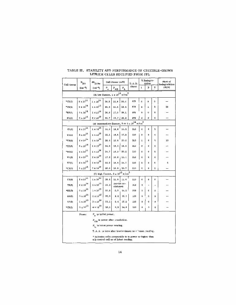
TABLE EI. STABILITY AND PERFORMANCE OF CRUCIBLE-GROWN LITHIUM CELLS RECEIVED FROM JPL
mD/- cell Power (mW) :ell Group NDo T* A* B.
(cm-3) (cm-4) Po PAB PL (days)
start of % Redegra- dation Redegradatior
I P v (days)
(A) low fluence, 1 x e/cm2
*C1(1)
'TZ(1)
*H2(1)
H W )
2
2
2
5
5
5
2
1
(B) intermediate fluence, 3 or 5 x 10¹⁴ e/cm2 - 31.8
30.1
26.4
24.3
24.7
17.4
25.2
25.0 - (C) high fluenci -
28.4
2 5 . 3
2 5 . 2
20.9
25.1
25.1 -
- 13.8
16.6
12.6
13.5
14.0
1 0 . 8
10.8
13.0
3 x 1
-
15.5
17.2
2 0 . 2
19.5
20.5
15.4
18.7
20. 7 _.
' e/cm"
(series re- sistance)
P is initial power.
PAB is power after irradiation.
P is latest power reading. L
313
110
313
313
110
313
110
110 -
110
313
313
110
110
110 -
- 0
0
1
0
0
0
3
0 - - 0
0
0
0
0
0 -
- 0
0
0
0
0
0
3
0 -
- 0
0
0
0
0 -
- 0
0
0
0
0
0
0
0 - - 0
0
0
0
0 -
T.A. B. is time after bombardment as of latest reading.
* indicates cells comparable to in power or higher than n/p control cell a s of latest reading.
14
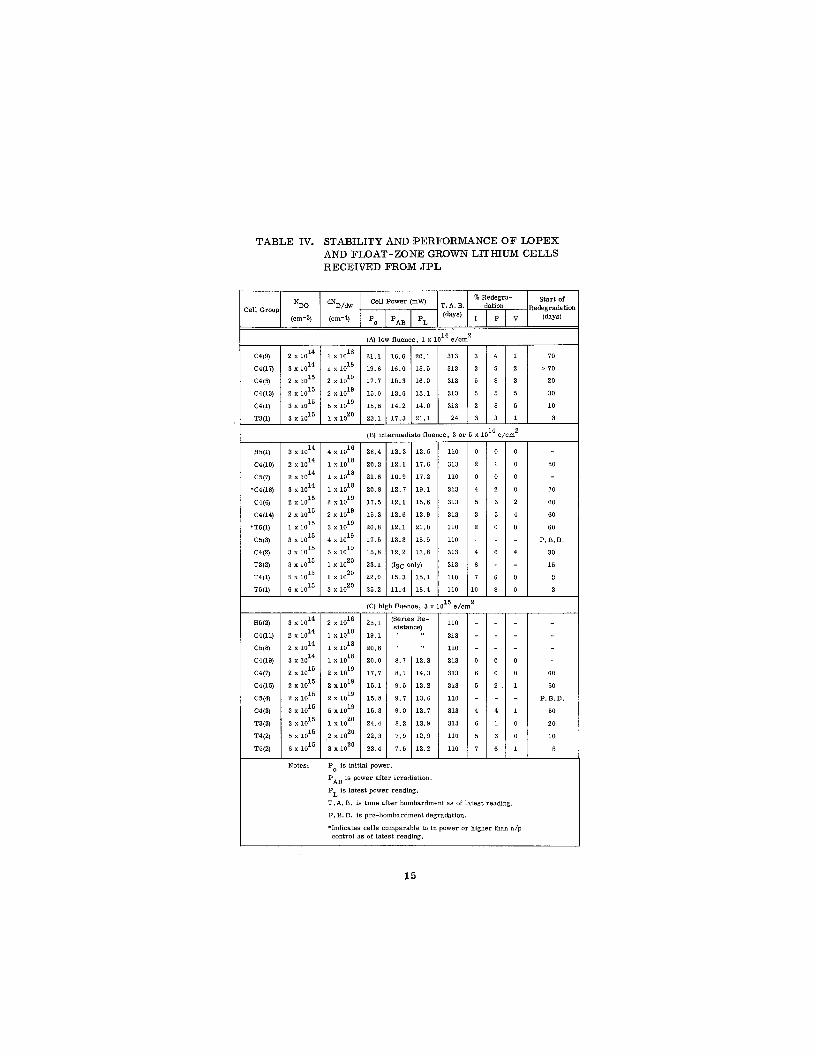
TABLE IV. STABILITY AND PERFORMANCE O F LOPEX
RECEIVED FROM JPL AND FLOAT-ZONE GROWN LlTHIUM CELLS
10
1BI intermediate fluence. 3 or 5 x loL4 e . , - 28.4
20.3
21.6
20.8
17 .5
15.3
26.8
11.5
15.8
23.1
22.9
25.2 __
__ 12 .3
1 2 . 1
10.9
1 2 . 7
12.1
12.6
12.1
13.3
12 .2
IISC
13.5
17.6
17.2
19.1
15 .6
13.9
21.0
15.9
13.8
1YI
IC) high fluence, 3 x
25,1 (Series Re- sistanoe)
19.1 " "
20.8
20.0
17.7
15.1
15.8
15.3
24.4
22.3
23.4 -
8 . 7
8 . 1
9.5
9. I
9.0
8.2
7.9
7.5 __
12.3
14 .3
13.2
13.6
12.7
13.9
12.9
12.2
- 110
313
110
313
313
313
110
110
313
313
110
110 - l5 e/< - 110
313
110
313
313
313
110
313
313
110
110 -
- 0
2
0
4
3
2
4
8
I
0 - -
0
6
5
4
6
5
I -
- 0
1
0
2
6
5
0
6
6
8 - -
0
0
2
4
1
3
6 -
n2 - 0
0
0
0
2
4
0
4
0
0 - -
0
0
1
1
0
0
1 -
Notes: P is initial power.
PAH 16 power after irradiation.
P is latest power reading.
T . A . B. is time after bombardment as of la tes t reading.
P. B. D. is pre-bombnrdment degradation.
'Indicates cells comparable to in power or higher than n/p control as of latest reading.
60
70
60
60
60
P.B.D.
30
1 5
3
3
G O
50
P.B.D.
50
20
10
5
15
In striking contrast to the stability of the crucible cells is the redegradation suffered by almost all groups of low-oxygen content cells ( F Z , Lopex) which is shown in the redegradation columns of Table IV. In these columns the current, voltage, and power redegradations do not always appear to correlate, e. g. , in T3(3) cells the current has redegraded by 6 percent whereas the power redegra- dation is only 1 percent. The reason for this is that open-circuit voltage re- covery is occurring at the same time that short-circuit current redegradation is occurring thus reducing, and in some cases eliminating, power redegradation. In general, but not always, the recovery-redegradation cycle in voltage is on a longer time scale than that of current. The redegradation columns also in- dicate that for the duration of these tests there is no correlation between percent redegradation in I o r V and lithium density; almost all groups suffer redegrada- tion regardless of density. * There is, however, one important parameter which correlates reasonably well with lithium doping level, that is, the time after bombardment at which redegradation starts. This is shown in the final column of Table IV. Clearly, the redegradation sets in faster the higher the lithium density. The greater degree of stability previously ascribed to float-zone cells with low lithium density (Ref. 2) must, in the light of more long-term data, be considered a matter of timing rather than freedom from recovery over an indef- inite period.
It appears that redegradation mechanisms, as well as the recovery mechanisms are related to the product of lithium density and lithium mobility. The stability data shows that the surest way to control the effects of this mobility-density product is through use of crucible cells where the mobility is reduced by a factor of -1000. The consequence is a large reduction in the recovery rate re- sulting, for the case of an impulse irradiation experienced in the laboratory, in a long period of low cell output. In the space environment where the irradia- tion rates are several orders of magnitude lower, this problem is greatly re- duced. However, if fast recovery is required and long term (>lo0 days) stability is not a consideration, float-zone cells on the low-side of the lithium density scale may be advantageously utilized. Caution must be exercised here since the time after irradiation at onset of redegradation is somewhat shorter after the lower fluences than it is after the higher fluences (see Table IV). This is probably due to the fact that during light irradiations less lithium is tied up in defects thus leaving more free lithium after irradiation. The application of high lithium density (dND/dw 2 1019 cm-4) FZ cells appears to be limited to situations such as a mission of short duration where heavy impulse irradiation is anticipated, or to situations where the ambient temperature is below room temperature.
The numbers in the initial power (Po) column of Tables 111 and IV indicate a wide range in initial cell performance. In general, the crucible cells a re of
*Correlation of percent voltage redegradation with lithium density is observed within one cell-lot, C4, in which redegradation increased with increasing density, see part B of this section and C4 cells in Table IV.
16
better initial quality than the float-zone cells. Several groups of crucible cells are competitive with commercial n/p cells whereas only two groups of float- zone cells, H5(1) and T6(1) are competitive. The best of the crucible cells have rather low lithium densities; however, the high density C5(1), C5(2), and T7 crucible cells have respectably high power levels, as do the high density float- zone cells of group T5(1).
Asterisks appear in kont of the cell groups which display higher output powers at the latest reading than the immediate post-irradiation powers of 10 ohm-cm n/p control cells irradiated to the same fluence. * Table IV shows only two such groups, C4(18) and T6(1) whereas several groups appear in Table III. This can be taken as a further indication of the superiority of the crucible cells over the float - zone cells.
It is noted that the crucible-grown, antimony-doped C2 cells are not included in Table 111. These cells, as stated in part B of this section, have suffered no redegradation but have shown little recovery over ax1 year post-irradiation period and therefore look relatively uninteresting for application in near-room - temperature environments. At elevated temperatures (-100°C) these cells could be of practical interest, as indeed would be all crucible-grown cells. Conversely, interest in float-zone cells could be greater at temperatures slightly below room temperatures, say 0°C to -20°C.
In summary a number of facts have been established.
1. Initial Performance
Lithium-containing crucible-grown cells which have initial powers compet- itive with commercial 10 ohm-cm n/p cells for a wide range of lithium densi- ties have been tested. Only a small fraction of the lithium containing cells made from float-zone and Lopex silicon have been competitive in initial output.
2. Recovery
(a) FZ Cells
Float-zone cells without exception recover rapidly at room temperature with characteristic recovery times ranging from several hours to several days, the recovery time varying in- versely with the lithium density. Only cells with essentially no lithium in the region near the junction after irradiation fail to experience recovery.
*Note that some post-irradiation recovery has been observed in the n/p control cells - see Ref. 3.
17
(b) QC Cells
Recovery of crucible cells in general is a slow process at room temperature taking several months to greater than a year depending on the lithium density. The recovery curve is sometimes S-shaped with the greatest recovery slope occurring-1 to 10 months after irradiation. Two notable exceptions are T2 cells and T7 cells with recovered rapidly, much as float-zone cells would recover.
3. Stability
Over test periods ranging up to one year, crucible cells have been stable with only group T7(1) showing significant redegradation. Almost all float-zone cells tested show significant redegradation. The redegradation starts later and is somewhat less severe in lightly lithium-doped cells. Redegradation occurs in open-circuit voltage as well as short-circuit current, although the voltage re- degradation usually occurs later. Heavily irradiated cells with light lithium doping have less tendency to redegrade; however, they do have the tendency to develop series resistance.
Crucible-grown cells, then, are the better cells at room temperature and should afford interesting possibilities at elevated temperatures. From the groups of float-zone and Lopex cells tested it is evident that applications for these cells would be limited to short-term uee o r for use at temperatures be- low room temperature.
Two areas which have not been covered in the range of cell parameters merit further study.
(1) No float-zone cells in the intermediate density range (is3 x 1018
Heliotek cells in this density range, supplied under a previous NASA contract, were tested for post-irradiation stability (Ref. 2) and were found stable over a1 year within the then 5-percent error. Further tests on such cells would be advantageous with the more reproducible light source now available.
All the float-zone cells supplied, except H5 cells, have very low background densities of phosphorus (or arsenic), i. e., Np 5 1014 cm-3, equivalent to P 0 >50 ohm-cm. Float-zone cells with low lithium doping, 5 s 3 x 1OI8 cm-3, but
higher phosphorus doping should be tested. It is felt that the high background doping in such cells would avoid the series- resistance problem encountered at high fluences.
5 < 1019) have been tested. A group of dw
(2)
dw
18
SECTION 111
SOLAR CELL EXPERIMENTS ON THE COLD FINGER
A. GENERAL
Experimentation on solar cells with the cells mounted on a cold finger pre- viously described (Ref. 2) was continued during the present reportion period. The principal cell property measured in these experiments was the minority- carrier diffusion length, L, in the base region of the cell (Ref. 4). This meas- urement together with published mobility values (Ref. 5) enabled the calculation of the minority-carrier lifetime, r , through the equation L = 5, where D is the minority-carrier diffusion constant obtained from the mobility by the use of the Einstein relation.
The diffusion length measurement was accomplished using a 1-MeV Van de Graaff generator to supply the electron beam. Cell irradiations were also per- formed with this beam. Periodic measurements of diffusion length during elec- tron irradiation enabled the calculation of lifetime damage constant, K, , using the equation
where
T~~ is the lifetime prior to irradiation, and
d is the electron fluence.
After irradiation, diffusion length measurements vs cell temperature for tem- peratures ranging from 80°K to 380°K yielded Curves of lifetime temperature ( r vs TM) from which defect energy levels were obtained using Hall-Shockley- Read analysis (Ref. 6,7).
The lithium-containing cells tested on the cold finger up to this point have been made from quartz-crucible silicon. Since room temperature annealing of QC cells proceeds very slowly at room temperature, isothermal anneals were per- formed at elevated temperatures, up to 380"K, to study the recovery kinetics of these cells.
B. LIFETIME VS TEMPERATURE AND ANNEALING MEASUREMENTS
In the previous reporting period, two lithium containing cells made from antimony (Sb) doped silicon, C6A-18(2) and C6A-19(2), were tested. These
19
were actually 0.13 x 0.30-inch pieces cut from the cells to accommodate the size limitations of the cold finger apparatus. During a 6-hour, 373°K anneal after irradiation to a fluence of 3 x 10¹⁵ e/cm2 at a bombardment temperature, TB, of WOK, cell C6A-18(2) showed a tenfold increase in lifetime, while C6A- 19(2) showed only a twofold increase (Ref. 3). Pre-irradiation capacitance- voltage measurements indicated that C6A-19 (2) was more heavily doped with antimony than C6A-18(2). The annealing results raised the questions (1) is the lifetime recovery due to lithium diffusion as in phosphorus-doped cells, and ( 2 ) is the antimony somehow inhibiting recovery.
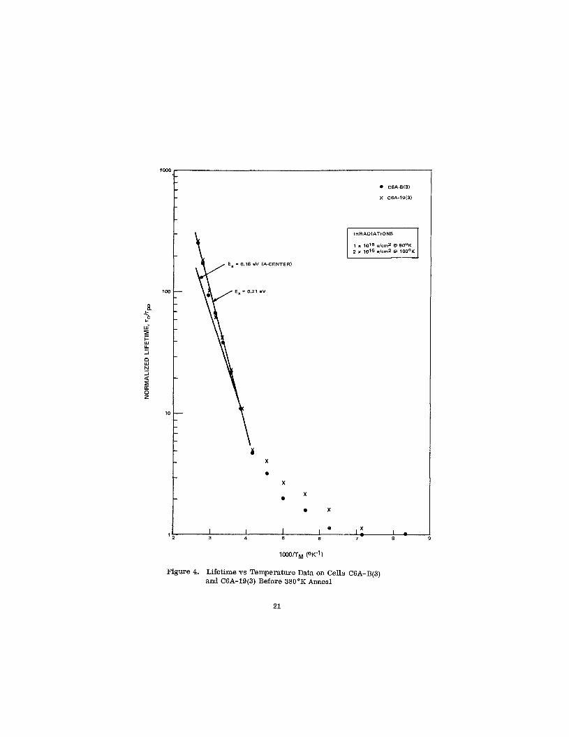
In an attempt to answer the first question, another piece of cell C6A-19, C6A- 19(3), was mounted on the cold finger together with a non-lithium m10 ohm-cm p/n control cell designated C6A-B(3). * The cells were irradiated and lifetime vs temperature measurements made after fluence increments of 1 x 10¹⁵ e/cm2 at 90°K bombardment temperature and 2 x 10¹⁵ e/cm2 at 100°K. The results of these measurements a re shown in Figure 4 in which I n ( T ~ / 'po) is plotted against inverse temperature, 1, OOO/Ty, where T is the low injection level (Adno <10-6)lifetime and rpo is the lifetime for heavily doped n-type silicon. The slope of this curve at high ro /rpo gives the activation energy, Ea, of the predominant defect. Figure 4 shows the curves for the lithium cell and the non-lithium cell to be virtually identical above ro/ -10. The activation energy is calculated to be 0.21 eV, a value which is close to the 0.18 eV found for the A center (oxygen-vacancy), which is shown for reference in Figure 4.
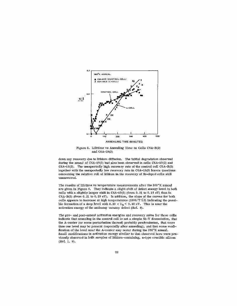
A 380°K anneal of 380 minutes duration was performed on these cells. The re- sults of the measurements performed during this anneal a re given in Figure 5 which is a plot of lifetime at 380'K after a time t of annealing, rot, normalized to the lifetime at the start of the anneal, T~~ , versus annealing time. Figure 5 shows that over the duration of the anneal the recovery in the lithium-free con- trol cell is approximately the same as that of the lithium cell. The shapes of the recovery curves do differ, however, with the non-lithium cell showing re- covery throughout the anneal while the lithium cell starts its recovery only after an initial degradation of x 50 minutes duration. The control cell has an initial characteristic recovery rate, S, of 6 x lom3 min-' . This rate is more than an order of magnitude higher than the value of 2 x min-1 calculated from pub- lished data (Ref. 8) for the dissociation of the antimony-vacancy defect. After approximately 70 minutes the recovery rate decreased to-1 x 10⁻³ min-1. The recovery rate in the lithium cell, C6A-19(3) was M 4 x 10⁻³ min-1. This was lower than the recovery rate previously (Ref. 3) observed for C6A-19(2) during a 373'K anneal, namely 7 x min-1. A possible explanation for the lower recovery rate in C6A-19/3) is the heavier damage it experienced, i. e., at the start of the anneal the diffusion length of C6A-19(3) was z 12 pm at 373°K while that of C6A-19(2) was x16 pm at 373°K. The more heavy damage in C6A-19(3) would imply heavier depletion of unbound lithium which would slow
*Six non-lithium control cells from lot C6A were generously furnished to us by Peter nes of Centralab.
20
1000 - - - e C6A-613)
- X C6A-1913)
- - -
1 x 10¹⁵ e/cm2 @ 9OoK
- E, = 0.18 eV (A-CENTER)
- loo - g -
k
ui - z L Y
8 E a .5
- h -
- -1
-1
0 z
10 I
4 X
0
X
0 X
o x
I I I I O X 1 1 1 2 3 4 5 6 7 8 9 -
21
0.3
38OoK ANNEAL
r O ip I t-0
I C6A-6(31 (CONTROL CELL) X CSA-19(3) (Li-CELL)
0.2
0.1 0 100 200 300 400 500
ANNEALING TIME (MINUTES)
Figure 5. Lifetime vs Annealing Time on Cells C6A-B(3) and C6A-19(3)
down any recovery due to lithium diffusion. The initial degradation observed during the anneal of C6A-19(3) had also been observed in cells C6A-19(2) and CGA-18(2). The unexpectedly high recovery rate of the control cell C6A-B(3) together with the unexpectedly low recovery rate in CGA-lS(3) leaves questions concerning the relative roll of lithium in the recovery of Sb-doped cells still unanswered.
The results of lifetime vs temperature measurements after the 380'K anneal are given in Figure 6 . They indicate a slight shift of defect energy level in both cells with a slightly larger shift in C6A-19(3) (from 0.21 to 0.18 eV) than in C6A-B(3) (from 0.21 to 0.19 eV). In addition, the slope of the curves for both cells appears to increase at high temperatures (1000/T <,3) indicating the possi- ble formation of a deep level with 0.30 < Ea < 0.40 eV. activation energy of the antimony vacancy defect (Ref. 8).
This is near the
The pre- and post-anneal activation energies and recovery rates for these cells indicate that annealing in the control cell is not a simple Sb-V dissociation, that the A-center (or some perturbation thereof) probably predominates, that more than one level may be present (especially after annealing), and that some modi- fication of the level near the A-center may occur during the 380°K anneal. Small modifications in activation energy similar to that observed here were pre- viously observed in bulk samples of lithium-containing, n-type crucible silicon (Ref. 1, 9).
22
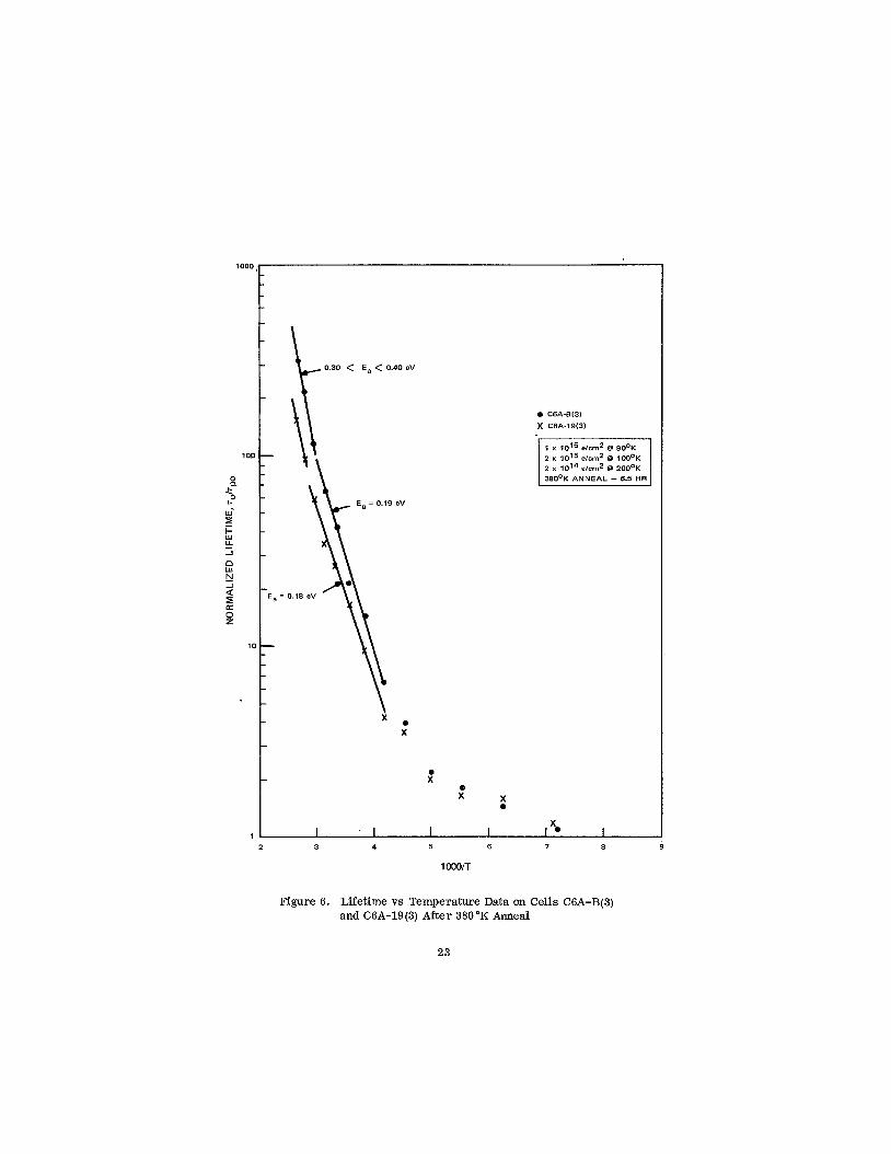
0 C 6 A - 8 W
X C6A-19W
1 x 10¹⁵ e/crnz B 90% 2 x 10¹⁵ eicrnz B I O O ~ K 2 x 1 0 1 ~ eicrnz B ZOOOK
x' X X
0
1 I I I I 2 3 4 5 6 7 8
1000/T
Figure 6. Lifetime vs Temperature Data on Cells C6A-B(3) and C6A-19(3) A f t e r 380°K Anneal
23
In another cold finger experiment lithium-containing cells C6B-20(1) and C6C- 20(1) were studied. Both cells were made from crucible grown silicon and they had nearly identical donor density profiles, as calculated from capacitance- volta e measurements, near the junction NDO w 2 x ld4 and dND/dw w 8 x 1% Cell C6B-20(1) was initially antimony-doped to a resistivity of 30 ohm-cm while C6C-20(1) was phosphorus-doped to 27.5 ohm-cm (Ref. 10). Thus the difference between these cells was the initial dopant; the purpose of the experiment was to investigate how this difference effected cell behavior. Cell C6B-20(1) also afforded the possibility of comparisons with the more heavily Sb-doped C6A-18(2) and C6A-19(2) ( -10 $2-cm and -3 Q-cm, respectively),
Unfortunately, little annealing data was obtained in this experiment since the buss-bar contact of first C6C-20(1) and later C6B-20(1) became separated from the cell after several irradiations and thermal cycles between 80°K and 340'K. Lifetime vs temperature measurements were made on both cells after irradia- tion and a defect activation energy 0.17 5 Ea 5 0.20 eV was found for both cells indicating the same predominant defect as in the previously tested cells, the A- center. A 0 . 5 hour, 373 "K anneal was performed on C6B-20(1) before contact separation occurred. In the first 18 minutes the diffusion length dropped from 17 pm to 13 pm. This was followed by the recovery, the diffusion length in- creasing back to 1 7 pm at 26 minutes, then contact was lost. Thus C6B-20(1) was showing similar annealing behavior to the other lithium-containing, Sb- doped cells tested, a short term degradation followed by recovery, when the experiment was terminated.
C. DAMAGE CONSTANT VS BOMBARDMENT TEMPERATURE
In addition to the experiments reported on in part B of this section, cell damage constants were measured as a function of bombardment temperature. The initial irradiations were performed at 90 OK. Then irradiations were made at successively higher temperatures. Measurements of diffusion length were made periodically during bombardment in the following manner: the irradiation was stopped momentarily and a measurement was first made at 90°K, then the cell temperature was raised to 200°K to anneal out all divacancies (Ref. 11) and a second measurement was made at 200°K, then the cell temperature was dropped back to 90 OK and a third measurement was made at 90 OK after which the irradiation was continued. The first measurement gave the lifetime damage at 90'K measurement temperature with the effect of divacancies included; the second and third gave the damage constant at 200'K and 90°K measurement temperature, respectively, after the divacancy contribution to the damage con- stant had been annealed out. Throughout the remainder of this section the data cited will be that taken after divacancy anneal unless otherwise specified.
Measurements of the lifetime damage constant, K, , were made for cells C6A-19(3) and C6A-B(3) for bombardment temperatures, TB, of 90°K, 100°K, and 200°K, the incremental fluences at these temperatures being 1 x
24
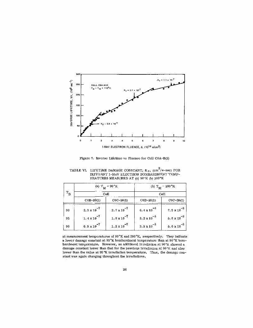
2 x 10¹⁵, and 1 x 10¹⁵ e/cm2, respectively. Table V (a) gives the K, values at 90°K measurement temperature, and (b) a t 200 OK measurement temperature. Both cells show higher values at 90'K measurement temperature than at 200'K measurement temperature. This is expected since the Fermi level is at 0,08 at 90'K and at = E, - 0.19 at 200°K. Consequently the A-center is a more active recombination center for holes at 90"K, being negatively charged at this temperature. Cell C6A-19(3) displays a w a g e constant which increases with increasing bombardment temperature. This is in agreement with carr ier re- moval results previously obtained on bulk samples (Ref. ly 9). Cell C6A-B(3), the lithium-free cell, however, showed a lower damage constant at 100°K than at 90°K, a very surprising result. A possible explanation of this behavior is found in Figure 7 which gives a plot of 1 / ~ vs fl taken from a separate experi- ment on C6A-B(2) which is an adjacent piece of the cell under consideration. This curye was taken during an irradiation at T B= 110'K. The measurements were made during irradiation at the bombardment temperature T M = TB and thus reflect the &vacancy contribution as well as the impurity defect contribution to the damage constant. The damage constant, K 7 which is the slope of the curve, is seen to change twice, first at fi x 2 x IO1' e/cm2 and then again at x 7 x 10¹⁴ e/cm2. The bombardment temperature dependence values have meaning only in the fluence region where K, has a constant value for a given bombardment temperature. In the experiments from which Table V was gen- erated there was a single K, value for each bombardment temperature. How- ever, in view of the results it must be assumed that the K , value changed some- where near the damage level reached after the 90°K irradiation, and that the readings in Table V are, therefore] not valid in the case of cell C6A-B(3).
Ec -
C 6A-B (3)
1.9 x
2 TABLE V. LIFETIME DAMAGE CONSTANT, K, (cm /e-sec) FOR THREE 1-MeV ELECTRON BOMBARDMENT TEMPERATURES MEAS- URED AT (a) 90"K, (b) 200°K
C6A-19 (3)
2.2 x
(a) TM = 90'K
200
I 100 I 2 . 8 ~ 1 0 - ~ I 1.7
6.0 x
(b) TM = 200°K I
1 . 4 ~ 1 0 - ~ 1 3.7 x 1 9.0 x10⁻⁸ 1 2.2 I
Damage constant versus bombardment temperature measurements were also attempted on cells C6B-20(1) and C6C-20(1). The fluence increments in these experiments were reduced, but the same difficulties arose as in the case of C6A-B(3). Table VI (a) and (b) gives the observed K, values for the two cells
25
0 1 2 3 4 5 6 7 8 9 10
I-MeV ELECTRON FLUENCE, @, e/crn2)
TB
90
95
90
Figure 7. Inverse Lifetime vs Fluence for Cell C6A-B(2)
(a) TM = 90°K (b) TM = 200'K
Cell Cell
C6C-20 (1) C6B-20(1) C6C-20(1) C6B-20(1)
2.3 2.7 6.4 x lo-' 7.5 x
1 .4 1 . 8 x 3.2 x lo-' 5.8 x low8
0.9 1.2 3.5 x lo-' 5.6 x
26
The change in damage constant during irradiation adds significantly to the diffi- culty of making the measurement. The experiments performed so fa r indicate that very light irradiations might be the best way to obtain meaningful data.. However, it is evident that after a set of runs at different bombardment tem- peratures, a repeat run at the original bombardment temperature will be re- quired as a check on the constancy of the value of K 7 at that temperature.
In terms of the physical parameters,
ANT K, =- u v A# P P’
where
3 AN is the number of recombination centers per cm created per unit
is the capture cross-section of the center for holes, and
is the hole thermal velocity.
fluence increment,
u
v P
P
If there is more than one recombination center formed the overall damage con- stant is the sum of the damage constants for the individual centers (provided the interaction between centers is small). A change in K, during irradiation would imply some change in ANT/ or up. The former could change if the supply of one of the defect constituents is greatly depleted, e. g., if oxygen is depleted in the case of the A-center (0-V); the latter could change if the Fermi level moved through the defect level during irradiation. Neither possibility looks feasible if the A-center is the predominant defect since the oxygen content of crucible silicon is large ( e/cm2) and since the Fermi level at 90°K is at%Ec - 0.08 eV, well above the A-center level of Ec - 0.18 eV. It appears that only the presence of another defect, either one with a level near Ec - 0.08 eV, or a defect with a deeper level in which one of the constituents is available in limited amounts, e. g. , Sb-V or Li -0-V, could cause changes in K during irradiation.
27
S E C T I O N IV
H A L L A N D R E S I S T I V I T Y M E A S U R E M E N T S
A. INTRODUCTION
The objectives of the Hall and resistivity measurements on bulk-silicon samples diffused with lithium are (1) to determine the dependence of carrier- removal on lithium concentration, oxygen concentration, and electron fluences at low and high bombardment temperatures, and (2) to determine the dependence of annealing at room temperature on the same parameters as for carrier- removal. To achieve these objectives, ingots of high resistivity FZ-refined silicon, Monex, and QC-grown silicon were procured and are presently being fabricated into Hall bars. Measurements on Hall samples fabricated from silicon procured during the last contract period (Ref. 2) were irradiated and measured. These results will be presented in this report. A complete descrip- tion of the methods and techniques of these measurements can be found in Reference 2.
B. TEMPERATURE DEPENDENCE OF CARRIER-REMOVAL RATE
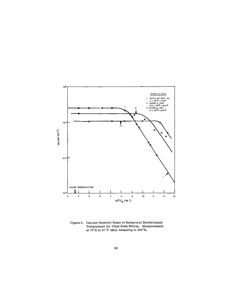
Sample H9-1 fabricated from 1500 ohm-cm float-zone refined silicon and diffused with lithium to a concentration of 5 x l O I 4 Li/cm3 was irradiated at several bombardment temperatures, and then the rate of carrier-removal was determined after each bombardment. This sample ( % l o ohm-cm) is very lightly doped with lithium compared to samples which were bombarded and measured previously (Ref. 3). The results obtained on H9-1 a r e shown in Figure 8 as curve I11 together with the results of Figure 13, Reference 3. Curve I1 was obtained on sample H4-2 doped with lithium to a concentration of 3.2 x 10¹⁵ Li/cm3, and curve I was obtained on four samples doped with lithium to a concentration of 2 x 10¹⁶ Li/cm3. These three concentrations cover approxi- mately the range of lithium concentrations which have been measured in the solar cells furnished to date by JPL. The doping densities in the solar cells a re those measured within a few microns the junction by capacitance techniques.
It was pointed out in the First Quarterly Report (Ref. 3) that there a re two im- portant points to note in Figure 8, namely, the shift of curves II and I11 along the temperature axis to lower temperatures relative to curve I, and the lower carrier-removal rate of the higher-resistivity samples (H4-2 and H9-1) meas- ured at the higher bombardment temperatures. This shift of curves I1 and I11 was expected since the interstitial-vacancy-close-pair model (Ref. 12) predicts this dependence of carrier removal on resistivity. The additional data obtained on H9-1 seems to confirm this trend which was observed previously. It appears that the close-pair theory provides a valid description of our results.
28
ZONE SILICON
I DATA OF REF. 10.
II SAMPLE H4-2 2 x 10¹⁶ ~11cm3
3.2 x 10¹⁵ Li/om3 Ill SAMPLE H9-1
5 x 10¹⁴ ~ i1cm3
ROOM TEMPERATURE
10-3 I I I I I 1 1 1 1 1 3 4 5 6 7 8 9 10 11 12 13
1 0 % ~ P K - ~ )
Figwe 8. Carrier-Removal Rates vs Reciprocal Bombardment Temperature for Float-Zone Silicon. Measurements at 79 "K to 81 "K After Annealing to 200°K.
29
The lower &/A@ values at high bombardment temperatures (e. g., 0 .18 cm-l and 0 . 1 cm-1 for samples H4-2 and H9-1) seem to confirm the experimental results of Reference 13, that the carrier-removal rate measured at high bom- bardment temperature decreases with increasing resistivity. There is not any existing physical model to explain this dependence on resistivity; however, the results indicate that the probability of forming a vacancy-impurity defect increases with an increase in the density of impurities. The mathematical model for this is elaborated in later discussions.
C. ANNEALING AT ROOM TEMPERATURE
1. Carrier Density Changes
One of the important properties of irradiated lithium-doped silicon is the annealing at room temperature (297'K) of the damage, and the recovery of elec- trical parameters to their pre-irradiation values. The annealing properties of these silicon samples and their dependence on resistivity, oxygen content, and fluence are data which are very important to the design of practical solar cells, Results of annealing studies obtained on sample H9-1 (%lo Q-cm) are shown in Figure 9 together with the results of Figure 16 , Reference 3 for comparison. The unannealed fraction fn of the carrier density is plotted as a function of annealing time at room temperature (TA = 297°K). Measurements of carrier density were made at a reference temperature of TM = 80°K. Following an annealing period of 1 5 0 hours at TA = 297"K, sample H9-1 was annealed for 20 minutes at a temperature of 373 "K. The change in carrier density that took place is shown as a dotted line in Figure 9. In complete contrast to the behavior of the three other samples, H9-1 did not indicate any increase in the carr ier density as a function of annealing time but rather a slight decrease at TA = 297'K. The carrier density increased following the high temperature annealing cycle at TA = 373°K.
The behavior of the lithium concentration during the annealing cycle can be in- ferred from the behavior of the carr ier density measured at a temperature of 297°K. These measurements a re shown in Figure 1 0 where the unannealed carrier density fn versus annealing time is shown for sample H9-1 together with the data of Figure 16 , Reference 3 for comparison. In contrast to the behavior of the other samples shown in Figure 10 which were heavily doped with lithium, the carr ier density of sample H9-1 decreased continuously as a function of annealing time. Thus, a loss of lithium as a function of time was observed on H9-1 instead of a gain in lithium concentration as observed on the other samples of low resistivity. This apparent dissociation of defect centers with the appear- ance of free lithium was observed to occur only after sample H9-1 was annealed for twenty minutes a t a temperature of 373°K. This increase of annealing temp- erature and recovery of carrier density is shown as the dotted line in Figure 10 at an annealing time of approximately 150 hours.
30
1 .o
z 2 3 0.4
a
0.2
& TA = 373'K Tw = 800K TA = 297OK
0 H4-5
Tw = 297OK TA = 2970K - 0 H4-5
X H5-5 13 H8-1 e ~ 9 - i -
101 100 10 102
ANNEALING TIME (HOURS)
Figure 9. Unannealed Fraction of Carrier Density vs Annealing Time for Four Samples of Float-Zone Silicon Annealed at a Temperature of 297°K and Measured at 80°K
0 I I I
ANNEALING TIME (HOURS)
Figure 10. Unannealed Fraction of Carrier Density vs Annealing Time for Four Samples of Float-Zone Silicon Annealed and Measured at a Temperature of 297 "K
31
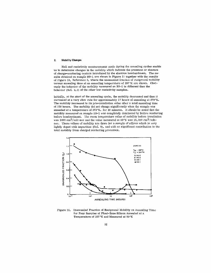
2. Mobility Changes
Hall and resistivity measurements made during the annealing cycles enable us to determine changes in the mobility which indicate the presence o r absence of charge-scattering centers introduced by the electron bombardment. The re- sults obtained on sample H9-1 are shown in Figure 11 together with the results of Figure 18, Reference 3, where the unannealed fraction of reciprocal mobility versus annealing time at an annealing temperature of 297 "K are shown. Obvi- ously the behavior of the mobility measured on H9-1 is different than the behavior (Ref. 2,3) of the other low resistivity samples.
Initially, a t the start of the annealing cycle, the mobility decreased and then it increased at a very slow rate for approximately 17 hours of annealing at 279 "K. The mobility increased to its pre-irradiation value after a total annealing time of 150 hours. The mobility did not change significantly when the sample was annealed at a temperature of 373°K. for 20 minutes. It should be noted that the mobility measured on sample H9-1 was completely dominated by lattice scattering before bombardment. The room temperature value of mobility before irradiation was 1600 cm2/volt-sec and the value measured at 80°K was 15,000 cm2/volt- sec. These values of mobility a re those for a sample of silicon which is very lightly doped with impurities (Ref. 5), and with no significant contribution to the total mobility from charged scattering processes.
1.1 -
+z 1.0
0
- z + 0.8 0
U 0 0.6 - Lu -I
Z 0.4 z z
- d
I$ a
= 0.2
-
-
0 - 1 0 1
1.1
+z 1.0
0 z + 0.8 0
U 0 0.6 Lu -I
Z 0.4 z z
d
I$ a
= 0.2
0 1 0 1 100 10 102 1 03
ZONE Si
TM = 80°K TA = 297OK
0 H4-5 X H5-5 0 H8-1
H9-1
100 10 102 1 03
ANNEALING TIME (HOURS)
Figure 11. Unannealed Fraction of Reciprocal Mobility vs Annealing Time for Four Samples of Float-Zone Silicon Annealed at a Temperature of 297°K and Measured at 80 "K
32
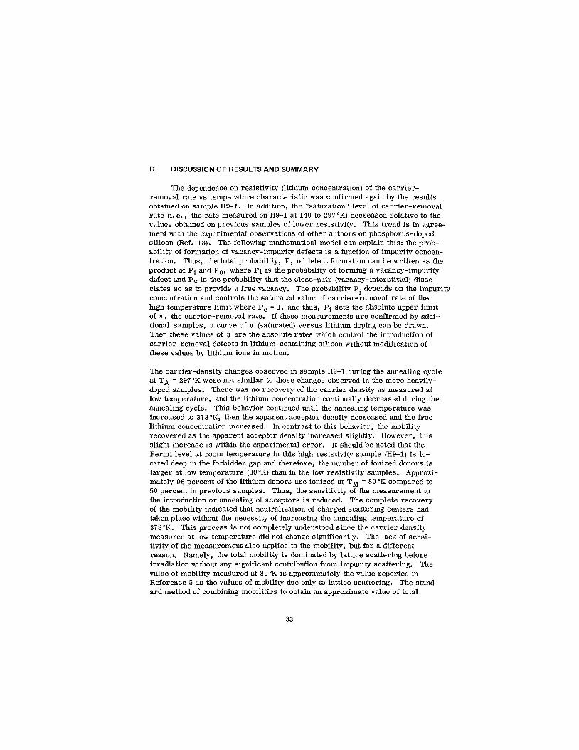
D. DISCUSSION OF RESULTS AND SUMMARY
The dependence on resistivity (lithium concentration) of the carrier- removal rate vs temperature characteristic was confirmed again by the results obtained on sample H9-1. In addition, the "saturation" level of carrier-removal rate (i. e., the rate measured on H9-1 a t 140 to 297'K) decreased relative to the values obtained on previous samples of lower resistivity. This trend is in agree- ment with the experimental observations of other authors on phosphorus-doped silicon (Ref. 13). The following mathematical model can explain this: the prob- ability of formation of vacancy-impurity defects is a function of impurity concen- tration. Thus, the total probability, P, of defect formation can be written as the product of P i and Pc, where Pi is the probability of forming a vacancy-impurity defect and Pc is the probability that the close-pair (vacancy-interstitial) disso- ciates so as to provide a free vacancy. The probability Pi depends on the impurity concentration and controls the saturated value of carrier-removal rate at the high temperature limit where P, = 1, and thus, Pi sets the absolute upper limit of P , the carrier-removal rate. If these measurements a re confirmed by addi- tional samples, a curve of P (saturated) versus lithium doping can be drawn. Then these values of P are the absolute rates which control the introduction of carrier-removal defects in lithium-containing silicon without modification of these values by lithium ions in motion.
The carrier-density changes observed in sample H9-1 during the annealing cycle a t TA = 297 "K were not similar to those changes observed in the more heavily- doped samples. There was no recovery of the carr ier density as measured at low temperature, and the lithium concentration continually decreased during the annealing cycle. This behavior continued until the annealing temperature was increased to 373"K, then the apparent acceptor density decreased and the free lithium concentration increased. In contrast to this behavior, the mobility recovered as the apparent acceptor density increased slightly. However, this slight increase is within the experimental error. It should be noted that the Fermi level at room temperature in this high resistivity sample (H9-1) is lo- cated deep in the forbidden gap and therefore, the number of ionized donors is larger at low temperature (80°K) than in the low resistivity samples. Approxi- mately 96 percent of the lithium donors are ionized at TM = 80°K compared to 50 percent in previous samples. Thus, the sensitivity of the measurement to the introduction or annealing of acceptors is reduced. The complete recovery of the mobility indicated that neutralization of charged scattering centers had taken place without the necessity of increasing the annealing temperature of 373 OK. This process is not completely understood since the carrier density measured at low temperature did not change significantly. The lack of sensi- tivity of the measurement also applies to the mobility, but for a different reason. Namely, the total mobility is dominated by lattice scattering before irradiation without any significant contribution from impurity scattering. The value of mobility measured at 80°K is approximately the value reported in Reference 5 as the values of mobility due only to lattice scattering. The stand- ard method of combining mobilities to obtain an approximate value of total
33
mobility ~r T, is given by Equation (1)
l/FtOtal = l/rl + U P L . . . where
p I is the mobility due to ionized impurity scattering, and
p is the mobility due to lattice scattering.
Inserting the experimental value of ptotal = 1.1 x 10⁴ (TM = 80'K) cm2/sec-volt measured right after irradiation, and p L = 1.5 x 104 cm2/sec-volt, and assuming that p L is not changed during bombardment, Equation (1) gives pI = 4.1 x l o 4 cm2/sec-volt.
The bombardment reduced the total mobility p by 27 percent. Conwell gives a graph in Reference 14 which makes it possible to determine rI without using Equation (1). This graph yields a value of pI = 1.5 x l o 5 cm2/sec-volt, which is approximately a factor of 2.5 times as large as the value obtained using Equation (1). Thus, in this situation, the use of Equation (1) provides a poor approximation, and can not be used to obtain PI. The observed change of 27 percent produced by irradiation should have produced a similar change in carr ier density when the mobility recovered during the annealing cycle, assuming that the scattering centers were singly charged, however, this was not the case. There does not appear to be any simple explanation why the change in mobility did not correlate with the change in carrier density. Additional samples of this specific type will be measured in future work and measurements should provide the data to explain these results.
34
SECTION V
DIFFUSION-CONSTANT MEASUREMENTS
A. GENERAL
The recovery of radiation-induced damage in lithium-doped silicon has been shown to be determined and controlled by the diffusion of lithium ions. For further elucidation of the recovery process, it would then be highly advantageous to determine the diffusion properties of lithium ions in any device incorporating lithium as a radiation-resistant dopant. These properties would then serve as a valuable aid in optimizing such devices.
B. DISCUSSION
The diffusion of lithium in silicon over a wide range of temperatures has been reported previously by several authors (Ref. 15, 16). These workers generally used some sort of ion drift technique incorporating the diffusion of lithium (n-type dopant) into a lightly doped p-type base. The free-lithium ion- diffusion constant in high punty silicon at room temperatures was measured to be about 2 ~ l O - l ~ cm2/sec (Ref. 15) with an activation energy of -0.66 ev. How- ever, Pel1 (Ref. 16) has shown that the diffusion constant can be some 3 orders of magnitude lower if oxygen is present in the silicon to a concentration of about 1 O l 8 / c d , not uncommon in QC material. In addition, Li-acceptor and Li- dislocation interactions have a similar effect in lowering the diffusion constant. Since solar cells are quite different devices from those used by the above authors, it appears highly desirable to determine nondestructively the diffusion properties of the lithium ion in the actual device being studied. Last year's final report (Ref. 2) introduced such a technique and a brief description is given below to familiarize the reader with the terminology. The capacitance Ca (and corresponding depletion region width W d is measured for some applied voltage Va. Then a large negative bias Vb is impressed on the cell (typically 10 volts) for a period of time. Under the resulting field, E, the mobile ions drift toward the junction. This causes the capacitance, Ca, to increase very much like the increase in capacitance of a parallel-plate capacitor as the plates a re moved toward each other. Since these cells typically exhibit a linear l/C3 vs V char- acteristic, one must increase the applied voltage to maintain the same capaci- tance Ca. This change in applied voltage, AV,, is measured as a function of
time that the cell is biased at Vb. This !.&- is then proportional to the
lithium ion mobility and with the Einstein relation, one can determine the dif- fusion constant, D. Last year, D was measured at room temperature as a function of Wa, the distance from the metallurgical junction, and was found to increase as a function of this distance. In general, however, the value of D nearest the junction was about 2 x 10-15 cm2/sec, a factor of 10 below the free lithium diffusion constant. Diffusion constant measurements have now been
35
made as a function of temperature (-20°C to +40'C) for two distances (2.3 micro- meters and 4.3 micrometers) from the junction on one cell. This cell (C5-110) was chosen because of its simple density gradient (approximately linear), float- zone material (low oxygen content to prevent complexing), and low doping den- sity. This last property enables one to "reach" farther (i. e., a larger Wa) from the junction to measure D before the high voltage causes the junction to break down. The cell was soldered to a brass finger-apparatus and held at a constant temperature bath. The diffusion constant as a function of temperature for 2 junction distances is shown in Figure 12. The free lithium diffusion con- stant is also shown. Several factors a re noteworthy. First, the room tempera- ture is about a factor of 2 greater at Wa = 4.3 wm than at 2.3 wm, confirming measurements made last year, but the 4.3 pm diffusion constant is still another factor of 2 lower than the free lithium diffusion constant. Pel13 has shown the effect of oxygen in decreasing the Li diffusion constant. He shows that the effective Li diffusion constant, DEff is related to the free lithium diffusion constant Df by the relation
1 DEff = Df (0) 1 +-
C
where C is a rate constant equal to 1015 cm-3 at R. T. and(0) is the oxygen concentration. For DEff/DL = 1/2, (0) must be 1015Cm-3, not uncommon for F. Z . material. It should be noted here that a relatively large e r ror in the absolute value of D (-30 percent) is believed present, due, for example, to the uncertainty in the lithium density, backgroundphosphorus density and the measure- ment of AVa/At. However, lonly a 10 to 20 percent e r ror is believed present in the relative values of D. Thus, it may be than an oxygen content less than 1015 cm-3 exists in this cell. Second, the activation energy for the 4.3 pm diffusion process was found to be at 0.59 ev. It i s felt that this value, within the experi- mental error, is the actual activation energy of free lithium (0.66ev).
At 2.3 pm from the junction, the diffusion constant is about 1/4 that of the free lithium diffusion constant. In addition, the activation energy of the process was measured to be - 0.45 ev. This is rather difficult to explain since any Li- acceptor, Li-oxygen or Li-dislocation complex that would reduce the diffusion constant would tend also to increase, not decrease, the activation energy. For some reason, more free lithium becomes available for drift near the junction at lower temperatures. In summary then, experiments on one cell indicate that the diffusion constant increases with distance from the junction at room tem- perature and appears to approach the free lithium diffusion constant. At lower temperatures, (-10'C) the diffusion constants at 2.3pm and 4.3wm from the junc- tion a re equal (4 x (-7 x 10-16 cma/sec).
cm2/sec) to the free lithium diffusion constant
36
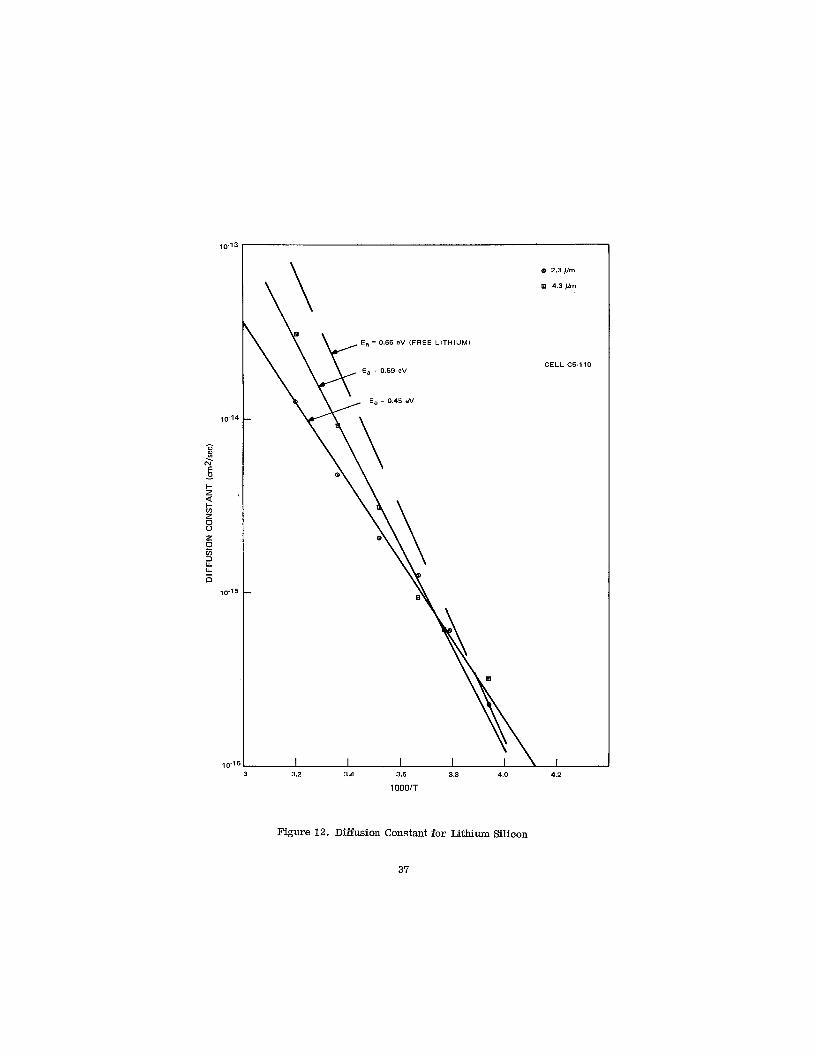
a 2.3 pm
m 4.3 pm
E, = 0.66 eV (FREE LITHIUM)
CELL C5-110
a 2.3 pm
m 4.3 pm
3 3.2 3.4 3.6 3.8 4.0 4.2
1000/T
Figure 12. Diffusion Constant for Lithium Silicon
37
SECTION VI
CONCLUSIONS AND FUTURE WORK
A. GENERAL
Some overall conclusions of the present reporting period are as follows: The models previously proposed for lithium action, in which lithium is involved in the original damage center and in recovery (see discussion in Ref. 3) are generally confirmed by the work, although some added complexity in room- temperature lithium transport phenomena has been detected in two ways by capacitance techniques. One case is the non-classical behavior of the diffusion constant within a few microns of the junction in a float-zone cell; the other is the anomalous absence of lithium-induced recovery of damage in an antimony- containing cell. The ground-rules for carrier removal in lithium-containing silicon are being developed and should, when completed, assist in the deter- mination of optimum cell designs.
E. SOLAR CELL STABILITY
1. Initial Performance
Lithium-containing crucible-grown solar cells which have initial powers competitive with commercial 10 ohm-cm n/p cells for a wide range of lithium densities have been tested. Only a small fraction of the lithium-containing cells made from float-zone and Lopex silicon have been competitive in initial output with the quartz-crucible cells.
2. Recovery
(a) FZ Cells
Float-zone cells, without exception, recover rapidly at room temperature with characteristic recovery times ranging from several bours to several days, the recovery time varying inversely with the lithium density. Only cells with no meas- surable amounts of lithium in the region near the junction after irradiation fail to experience recovery.
(b) QC Cells
Recovery of crucible cells, in general, is a slow process at room temperature, taking from several months to more than a year, depending on the lithium density. The recovery curve
38

is sometimes S-shaped with the greatest recovery slope occurring -1 to 1 0 months after irradiation. Two notable exceptions are T2 cells and T7 cells which recovered rapidly, much as float-zone cells would recover.
3. Stability
Over test periods ranging up to one year, crucible cells have been stable with only group T7(1) showing significant redegradation. Almost all float-zone cells that were tested have shown significant redegradation. in lightly lithium-doped cells starts later and is somewhat less severe. radation occurs in open-circuit voltage as well as short-circuit current, although the voltage redegradation usually occurs later. Heavily irradiated cells with light lithium doping have less tendency to redegrade; however, they do have the ten- dency to develop series resistance.
Crucible-grown cells, then, are operationally the better cells at room tempera- ture and should afford interesting possibilities of stability at elevated tempera- tures. From the groups of float-zone and Lopex cells tested, it is evident that applications for these cells would be limited to short-term use after irradiation or for use at temperatures below room temperature. The selection of silicon growth process is, thus, further demonstrated to be a parameter of great im- portance; however, the final decision may depend on the temperature regime anticipated for the cell.
The redegradation Redeg-
C. LOW-TEMPERATURE STUDIES ON CELLS
Defect energy levels obtained from lifetime versus temperature measure- ments for antimony-doped and phosphorus-doped lithium-containing, crucible- grown cells and for antimony-doped non-lithium, crucible-grown cells indicate that, as expected, the oxygen-vacancy (A-center) is the predominant defect causing lifetime degradation in these cells. A simultaneous 380°K anneal of an antimony-doped lithium cell and antimony-doped non-lithium cell resulted in similar recovery rates for both cells. Thus, the measurement did not succeed in isolating the effect of lithium in the recovery process. Therefore, it is still not clear why many lithium-diffused, antimony-containing p/n cells do not exhibit the expected recovery of electron damage. Measurements indicate that lithium is present in the active region. It is possible that cells contain a com- plexing agent (antimony, an unknown impurity, o r an unexpected defect), which prevents the lithium from diffusing damage centers in the usual way. More study of this interesting question is required.
Measurements of damage constant, K, at several temperatures near 100°K indicate that the damage is not strictly linear at this temperature. The rate varies with the extent of the cell damage.
39
D. HALL MEASUREMENTS
The trend of the results continued to confirm the dependence of carr ier density on initial lithium donor concentration as previously reported (Ref. 3). Annealing measurements taken on sample H9-1 (5 x 10¹⁴ Li/cm3) did not agree with the behavior of the more heavily doped samples. These results are con- sistent with a lack of sufficient free lithium to interact with the defect centers produced. A suitable model is one in which most of the lithium atoms are involved in unusually stable complexes. The lithium concentration of H9-1 (5 x 10¹⁴ Li/cm3) thus appears to be near to a lower limit below which the beneficial action of lithium in carrier recovery does not take place.
The absolute value of the saturated carrier-removal rate (i. e., the rate as measured at high temperatures, e. g., -150OC to room temperature) decreased by approximately a factor of 3 for an increase in resistivity by a factor of approximately 30 for lithium-doped samples. Also, 10 ohm-cm lithium-doped samples made from float-zone silicon appear to have approximately the same saturated carrier-removal rate as the 0.3 ohm-cm lithium-doped quartz- crucible silicon (Ref. 9). This is different from the case of phosphorus-doped silicon where, for a wide range of resistivities, carr ier removal rates for float-zone always stay well above those for quartz-crucible silicon (Ref. 13).
These conclusions still require confirmation. However, the results to date suggest that, following some confirmation tests, it may be possible to construct a design curve which relates the rate of lithium donor removal per unit particle flux (i. e. , carrier removal in the base region of a lithium-doped cell) to the original lithium doping level used in the silicon. This could probably be ex- tended, though with less accuracy, to a curve relating the radiation-induced change in silicon resistivity o r series resistance expected in a cell to a se t of processing parameters such as lithium diffusion and redistribution time. would then act as a design guide in specifying a cell fabrication process to fit a certain radiation environment and array characteristic.
This
E. DIFFUSION CONSTANT MEASUREMENTS
The tentative conclusion is thus that, in the important active region of the cell, the rate of recovery of minority-carrier lifetime with time after irradia- tion will not be uniform. One possible result is that the photovoltaic perform- ance may recover more rapidly for one region of the cell spectral response than for others. Presumably, the blue response would be slower to recover than "redder" wavelengths. This conclusion depends, however, on the validity of the measurements of these regions at the depletion edge.
40
F. FUTURE PLANS
1. Solar Cell Studies
Stability tests on cells from JPL's shipments No. 1 through 5 will be continued. Further investigations will be made into C8 cells, of which only a few have been irradiated to date.
The cold finger experiments will be continued using phosphorus-doped crucible cells (C6C cells) in the next experiments. Further attempts will be made to study the dependence of the damage constant, K,, on bombardment temperature.
2. Hall Measurements
Emphasis will be placed on correlating the Hall and resistivity measure- ments with the behavior of lifetime in solar cells at low bombardment tempera- tures. Hall and resistivity measurements will be continued on samples with low-lithium concentration and others with resistivities in the range of 0.3 to 10 ohm-cm. Hall samples of quartz-crucible and Monex silicon will be included in the measurements.
3. Diffusion Constant Measurements
The diffusion constants and activation energies for lithium diffusion at different distances from the metallurgical junction for cells of different growth techniques (e. g., float-zone, quartz-crucible, lopex) will be measured to try and elucidate the mechanisms involved in each case.
41
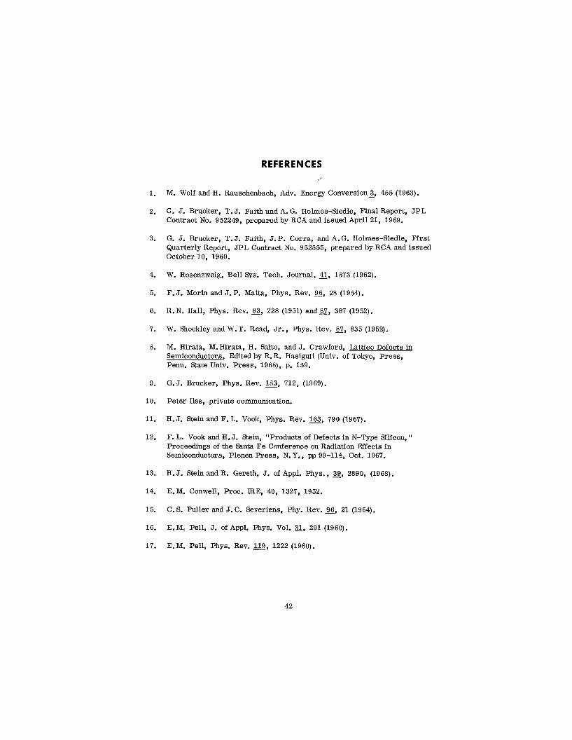
1.
2.
3.
4.
5.
6.
7.
8.
9.
10.
11.
12.
13.
14.
15.
16.
17.
REFERENCES
M. Wolf and H. Rauschenbach, Adv. Energy Conversion?, 455 (1963).
G. J. Brucker, T. J. Faith and A. G. Holmes-Siedle, Final Report, J P L Contract No. 952249, prepared by RCA and issued April 21, 1969.
G. J. Brucker, T.J. Faith, J.P. Corra, andA.G. Holmes-Siedle, First Quarterly Report, J P L Contract No. 952555, prepared by RCA and issued October 10, 1969.
W. Rosenzweig, Bell Sys. Tech. Journal, 41, 1573 (1962).
F. J. Morin and J. P. Maita, Phys. Rev. E, 28 (1954).
R.N. Hall, Phys. Rev. 83, 228 (1951) a n d g , 387 (1952).
W. Shocltley and W.T. Read, Jr., Phys. Rev. 87, 835 (1952).
M. Hirata, M.Hirata, H. Saito, and J. Crawford, Lattice Defects in Semiconductors, Edited by R.R. Hasiguti (Univ. of Tokyo, Press, Penn. State Univ. Press, 1968), p. 159.
G.J. Brucker, Phys. Rev. 183, 712, (1969).
Peter Iles, private communication.
H. J. Stein and F. L. Vook, Phys. Rev. 163, 790 (1967).
F. L. Vook and H. J. Stein, "Products of Defects in N-Type Silicon, Proceedings of the Santa Fe Conference on Radiation Effects i n Semiconductors, Plenen Press, N. Y., pp 99-114, Oct. 1967.
H. J. Stein and R. Gereth, J. of Appl. Phys., 39, 2890, (1968).
E.M. Conwell, Proc. IRE, 40, 1327, 1952.
C. S. Fuller and J. C. Severiens, Phy. Rev. 96, 21 (1954).
E.M. Pell, J. of Appl. Phys. Vol. 3l, 291 (1960).
E.M. Pell, Phys. Rev. 119, 1222 (1960).
42
' f
I ,
I ' RCA I Defense Electronic Products I Astro Electronics Division I Princeton, New JWSW
I I - i , , I