Embed Size (px)
Citation preview

Computers, Materials & Continua CMC, vol.65, no.2, pp.1015-1032, 2020
CMC. doi:10.32604/cmc.2020.011476 www.techscience.com/journal/cmc
Second Law Analysis and Optimization of Elliptical Pin Fin Heat Sinks Using Firefly Algorithm
Nawaf N. Hamadneh1, Waqar A. Khan2 and Ilyas Khan3, *
Abstract: One of the most significant considerations in the design of a heat sink is thermal management due to increasing thermal flux and miniature in size. These heat sinks utilize plate or pin fins depending upon the required heat dissipation rate. They are designed to optimize overall performance. Elliptical pin fin heat sinks enhance heat transfer rates and reduce the pumping power. In this study, the Firefly Algorithm is implemented to optimize heat sinks with elliptical pin-fins. The pin-fins are arranged in an inline fashion. The nature-inspired metaheuristic algorithm performs powerfully and efficiently in solving numerical global optimization problems. Based on mass, energy, and entropy balance, three models are developed for thermal resistance, hydraulic resistance, and entropy generation rate in the heat sink. The major axis is used as the characteristic length, and the maximum velocity is used as the reference velocity. The entropy generation rate comprises the combined effect of thermal resistance and pressure drop. The total EGR is minimized by utilizing the firefly algorithm. The optimization model utilizes analytical/empirical correlations for the heat transfer coefficients and friction factors. It is shown that both thermal resistance and pressure drop can be simultaneously optimized using this algorithm. It is demonstrated that the performance of FFA is much better than PPA.
Keywords: Firefly algorithm, mathematical models, entropy generation rate, elliptical pin-fin heat sinks, thermal resistance, pressure drop.
Nomenclature m : Fin parameter (m-1)
1C : Constant in Eq. (6)
bt : Base plate thickness (m) ν : Kinematic viscosity (m2/s)
fk : Thermal conductivity of fluid (Wm-1K-1)
*bt : Dimensionless base plate thickness H : Height of fin (m)
fR : Fin resistance (KW-1)
lR : Contact resistance (KW-1)
filmR : Film resistance (KW-1)
1 Department of Basic Sciences, College of Science and Theoretical Studies, Saudi Electronic University,
Riyadh, 11673, Saudi Arabia. 2 Department of Mechanical Engineering, College of Engineering, Prince Mohammad Bin Fahd University,
Al Khobar, 31952, Saudi Arabia. 3 Faculty of Mathematics and Statistics, Ton Duc Thang University, Ho Chi Minh City, 72915, Vietnam. * Corresponding Author: Ilyas Khan. Email: [email protected]. Received: 10 May 2020; Accepted: 26 June 2020.
1016 CMC, vol.65, no.2, pp.1015-1032, 2020
LN : Number of fins in longitudinal direction U∞
: Free stream velocity (ms-1)
TN : Number of fins in transverse direction *W : Dimensionless heat sink width *L : Characteristic length for elliptical fin maxU : Maximum velocity between fins (ms-1)
*TS :Dimensionless transverse pitch
cA : Cross-sectional area of elliptic fin (m2)
fh : Heat transfer coefficient for fin (Wm-2K-1)
( )E e : Complete elliptic integral of the second kind
*ReL: Reynolds number based on characteristic
length bh : Heat transfer coefficient for base surface
(Wm-2K-1) k : Thermal conductivity of fin material (Wm-
1K-1)
fA : Fin surface area (m2)
fη : Efficiency of fin P : Perimeter of fin (m) Pr : Prandtl number
* b : Dimensionless semi-minor axis *T
S : Dimensionless transverse pitch
*LS : Dimensionless longitudinal pitch
*a : Dimensionless semi-major axis *hsL : Dimensionless heat sink length
L: Length of heat sink (m) shN : Dimensionless entropy generation
rate due to heat transfer sfN : Dimensionless entropy generation
rate due to fluid friction sN : Total dimensionless of entropy
generation rate
1 Introduction The pin-fin heat sinks have been significantly employed to improve the overall performance of avionics, microelectronics, and defense systems. Among these, cylindrical, square, and elliptical pin-fin heat sinks are usually utilized. A detailed survey of the microchannel or pin-fin heat sinks can be found in Adham et al. [Adham, Mohd-Ghazali and Ahmad (2013); Dixit and Ghosh (2015); Khan (2004); Narendran, Gnanasekaran and Perumal (2018)].
1.1 Elliptical pin-fin heat sinks Elliptical fins represent a circular fin when axis-ratio is 1 and a flat plate when the axis ratio tends to zero. Furthermore, the elliptical fins are found to perform better than circular or square cross-sections [Khan (2004); Yang, Chu, Chen et al. (2007)]. Deshmukh et al. [Deshmukh and Warkhedkar (2013)] considered the fully shrouded inline, and staggered layout of elliptical pin-fin heat sinks and obtained the optimum design parameters experimentally. They also investigated the impacts of several relevant parameters, including base plate length, width, thickness, approach velocity, ambient temperature, etc. On the thermal resistance of the heat sink, they confirmed the results of Khan et al. [Khan (2004); Yang, Chu, Chen et al. (2007)]. Li et al. [Li, Davidson and Mantell (2005)] examined the friction and heat transfer from elliptical tubes of different axis ratios. They demonstrated that an elliptical tube could reduce the pressure drop by 30%-40% and enhance the average heat transfer rate by15%-35% compared to that of a circular tube. Matos et al. [Matos, Vargas, Laursen et al. (2001)] performed an optimization study in circular and elliptic tube heat exchangers. They studied the impacts of Reynold's number and

Second Law Analysis and Optimization of Elliptical Pin Fin Heat 1017
axis ratio on the Nusselt number for both circular and elliptic arrangements. Matos et al. [Matos, Laursen, Vargas et al. (2004)] optimized the total heat transfer rate for staggered arrangements of circular and elliptical tubes and concluded that elliptical tubes improve the overall performance and reduce the cost. Later, Matos et al. [Matos, Vargas, Laursen et al. (2004)] performed another detailed study to optimize the total heat transfer rate for both circular and elliptical tubes. They found 20% heat gain with the elliptical tubes. Sahiti et al. [Sahiti, Lemouedda, Stojkovic et al. (2006)] studied different pin-fin arrangements and investigated the overall thermal performance in terms of pertinent parameters. Samsal [Sasmal (2017)] investigated the momentum and heat transfer from an elliptic cylinder in CuO nanofluids numerically. It was demonstrated that the total drag coefficient and the Nusselt number rises with increasing volume fraction and the size of the CuO nanoparticles. Seyf et al. [Seyf and Layeghi (2010)] examined the forced convection numerically in elliptical pin-fin heat sinks. They solved governing equations using the FLUENT and demonstrated that the pressure drops and Nusselt number increase significantly with increasing Reynolds number and decreasing permeability. Baruah et al. [Baruah, Borah and Das (2016)] reported the effects of the axis ratio of elliptical pin-fins on the overall performance. They noticed a change in the overall performance with varying the shape of elliptical fins.
1.2 Optimization Optimization problems provide an active research field to the researchers in all areas. Therefore appropriate modeling and optimization algorithms must be chosen to solve these problems [Zhao, Hu, Xiong et al. (2020)]. In the optimization problems, the main objective is to determine the optimum value of the objective function through in the feasible area [Hamadneh, Khan, Khan et al. (2019)]. Many metaheuristic algorithms have been proposed for solving optimization problems. The Genetic algorithm (GA), Prey-Predator Algorithm (PPA), and Firefly algorithm (FFA) are some of the best use in this field [Hamadneh (2020)]. They provide useful strategies and have been developed to solve several engineering problems. Mohsin et al. [Mohsin, Maqbool and Khan (2009)] applied GA to optimize the cylindrical pin-fin heat sinks. They minimized the total EGR across cylindrical pin-fins. It was confirmed that all pertinent parameters could be optimized at the same time. Hamadneh et al. [Hamadneh, Khan and Tilahun (2018)] optimized the overall performance of a microchannel heat sink by using PPA. They developed a relationship between thermal resistance and pressure drop across the heat sink by using a radial basis function neural network. Khan et al. [Kadri, Khan and Ali (2013); Khan, Yovanovich and Culham (2006)] optimized the overall performance of microchannel heat sinks by employing entropy generation minimization (EGM) technique. The effects of governing parameters on the EGR are examined in the slip flow region. Hamadneh et al. [Hamadneh, Khan, Sathasivam et al. (2013)] considered the fins of different shapes to compare the overall performance. They discussed the consequences of the fin shapes on the overall performance and concluded that elliptical fins show higher efficiency than other geometries. Kim et al. [Kim, Moon and Kim (2011)] considered staggered elliptic dimples and optimized a cooling channel to enhance heat transfer and reduce pressure. They optimized models for the heat

1018 CMC, vol.65, no.2, pp.1015-1032, 2020
transfer and friction loss and obtained 32.8% increase in the heat-transfer rate and 34.6% decrease in the pressure loss. One of the essential tools of Swarm Intelligence is FFA that can be used in several engineering industries due to two main reasons. The first is the faster convergence under certain conditions, and the second is the smaller chance of sting into neighboring modes. FFA and its modifications have been used to optimize several engineering problems. It urges new investigators and algorithm creators to use this simple and very efficient algorithm for problem-solving. There are many key characteristics that make FFA very effective like it can solve the problems of continuous optimization, combinatorial optimization, constraint optimization, and it can deal with highly nonlinear, multi-modal optimization problems naturally and efficiently [Fister, Fister Jr, Yang et al. (2013); Tilahun, Ngnotchouye and Hamadneh (2017)]. As an example of the applied FFA, Mohanty [Mohanty (2016)] optimized a shell and tube heat exchanger using the FFA. The primary objective function was selected as the minimization of the total cost. The results reveal that the total cost can be reduced by 29% as compared to the original design. The above literature review reveals that the previous studies associated with the elliptical pin-fin heat sinks are either numerical or experimental, and no one employed metaheuristic algorithms to optimize these heat sinks. The objective of this paper is to model the elliptical pin-fin heat sinks theoretically and then optimize the model using a powerful and efficient FFA.
2 Problem formulation 2.1 Heat sink design model The schematic diagram for an inline elliptical pin-fin heat sink is depicted in Fig. 1. The length, width, and thickness of the base plate are assumed to be L, W, and bt , respectively. The major axis of the pin-fin in the stream-wise direction is a, and the minor axis is b, whereas the height of the pin-fin is H. The longitudinal and transverse pitches are SL and ST, respectively. The number of pin-fins in the stream-wise direction is NL, and in the transverse direction is NT. The total number of pin-fins is N=NT×NL.

Second Law Analysis and Optimization of Elliptical Pin Fin Heat 1019
Figure 1: Schematic diagram of the inline elliptical pin-fin heat sink
The thermal conductivities of the pin-fin material and air are k and fk , respectively. The ambient temperature of the air is T∞ and approach velocity is U∞. The characteristic length of the pin-fin is taken as *L 2a= . The convection heat transfer coefficient, h, is considered as constant in all the fins’ surface. The constant heat flux Q is applied at the bottom surface of the base plate. The size and the heat load of the sink are taken as the constraints. Following assumptions were used in the analysis: 1. The pin-fin tips are adiabatic. 2. The heat sink is fully shrouded. 3. The flow is fully developed, laminar, and steady. 4. No-slip boundary condition is applied at the base plate and the pin-fin surface. 5. The radiation heat transfer is negligible. 6. The thermophysical properties are taken to be constant
2.2 Thermal resistance model The thermal resistance of a system measures the thermal performance of a heat sink, and it accounts for the heat source on one side of the baseplate and a cooling medium on the other side. Fig. 2 shows all the resistances of the heat sink. Neglecting the effect of spreading resistance, the total thermal resistance of the heat sink ( hsR ) includes the base plate resistance and the resistance of the finned and un-finned surfaces. The resistance of the finned surface includes fin contact resistance as well as the resistance of each fin. Both resistances are in series. The equivalent of these resistances is in parallel with the un-finned (film) resistance. The equivalent of these series and parallel resistance is called fins resistance. This is explained in Fig. 2.

1020 CMC, vol.65, no.2, pp.1015-1032, 2020
Figure 2: Thermal resistance model for the pin-fin heat sink
The total thermal resistance of the heat sink hsR includes the material and the fins resistance and can be written as
chs
T TRQ
∞−= (1)
where cT is the chip temperature, T∞ is the ambient temperature, and Q is the given heat load.
hs m finsR R R= + (2)
where mR is the material resistance, and finsR is the fins resistance, and are given by
bm
tRkLW
= (3)
11fins
c f film
R NR R R
=+
+
(4)
with
1 1 1 tanh( ); ; ; and ( )
fc f film f
c f f f b c c
h PmHR R R mh Ac h A h LW NA mH kA
ηη
= = = = =−
where
*
*
*
*
* * *
1/2 1/3 1/2 1/31
*max max
max
; ; ; 2 ; 2 ( )
Re Pr ; 0.75 Re Pr2
Re ;Re ; 1
f c L T
f ff b LL
TLL
T
A L H A ab N N N L a P L E ek k
h C ha L
SU L U L U US
π
ν ν ∞
= = = = =
= =
= = =−
(5)
*
* *
*
0.785 0.2121
0.25 exp( 0.55 )( 1)
LT L
T
SC S S
S+ −
=−
(6)

Second Law Analysis and Optimization of Elliptical Pin Fin Heat 1021
2.3 Pressure drop model The pressure drop ( P∆ ) performs a very crucial part in the performance of heat sinks and is known as hydraulic resistance of the heat sink [Baruah, Borah and Das (2016); Khan (2004)]. As the pressure drop increases, the airflow rate decreases through the heat sink. Neglecting the abrupt contraction and expansion effects, the pressure drop across the heat sink can be written as
2 max2 L
UP f Nρ∆ = × × (7)
where ρ is the density of air, f is the friction. For inline arrangement, the friction factor can be written as Khan [Khan (2004)].
*1 * 1.1
45.78[0.233 Re ]( 1) L
T
f Ks
= +−
(8)
The correction factor 1K depends upon the flow geometry and arrangement of pin-fins
[Khan (2004)]. 0.0553
*1.09 / Re*
1 *1.0091
L
T
T
SKS
= −
(9)
The maximum velocity maxU in the minimum free cross-section between two rows is used in the calculations and is given by Khan [Khan (2004)]:
*
*max 1
T
T
SU U
S ∞=−
(10)
2.4 Entropy generation model In addition to the assumptions made in Section 2.1, it is assumed that the spreading or constriction resistance is negligible, and the contact of the fin with the base plate is perfect. Following Bejan et al. [Bejan (1996); Khan (2004)], the total EGR due to heat transfer and fluid friction can be written as
2
gen,h gen,fS Sgen hsb
Q m PS RT T Tρ∞ ∞
∆= + = +
(11)
The mass flow rate through the pin-fins can be written as * *
T Tm U N S HLρ ∞= (12)
The dimensionless EGR can be written as
s sh sfN N N= + (13)
The simplified expression can be written as

1022 CMC, vol.65, no.2, pp.1015-1032, 2020
( )** *
* *
*
* ** * * *
*2
2,max
1ReRe Re
1 Re2
b
L Lb Leq f eqL L
T L
tTNsNuT LW Nk Nu k LW N a b
L
B N f S
γη π
γ
∞
= ⋅ + +
+ −
⋅ ⋅ ⋅ ⋅
(14)
where the dimensionless parameters are defined as / eq fk k k= (dimensionless thermal conductivity ratio); 3 2/B kT Qρν ∞= ( dimensionless duty parameter).
3 Optimization procedure The FFA looks for optimal solutions based on the information they collect through several iterations [Mohanty (2016); Tilahun, Ngnotchouye and Hamadneh (2017)]. To avoid local search, FFA uses a random distribution that makes the algorithm suitable for global optimization. In the next section, we will review the essential aspects of FFA. In this study, SN is the objective function that is to be minimized subject to constraints. Accordingly, the mathematical formulation of optimization
SN can be written as
Minimize ( ) Sf x N= (15)
Subject to 4 10;0.01 1;0.1 1;Uγ ε∞≤ ≤ ≤ ≤ ≤ ≤ (16)
* *1.5 3;1.5 3T L
S S≤ ≤ ≤ ≤ We focus on finding the optimal values of the above parameters through FFA. The design parameters are U∞,
*TS ,
*LS , γ and ε . The other fixed parameters are given in Tab. 1.
Table 1: Constant values of fixed parameters Fixed Parameters Values a (m) 0.025
W (m) 0.5
𝜌𝜌 (kg/m3) 1.1614
𝜈𝜈 (m2/s) 51.58 10−×
𝑇𝑇∞ (K) 300
k (W/m-K) 237
𝑘𝑘𝑓𝑓(W/m-K) 0.026
𝑇𝑇𝑏𝑏(K) 350
rp
0.71

Second Law Analysis and Optimization of Elliptical Pin Fin Heat 1023
3.1 Firefly evaluation Based on the behavior of fireflies, Yang [Yang (2013)] developed an algorithm called FFA as a highly effective algorithm. This algorithm has the flexibility to deal with continuous problems and clustering because of its several advantages [Khan, Hamadneh, Tilahun et al. (2016); Singh, Patel and Neema (2019); Yang (2013)]. The main advantages of FFA are divided into two parts: dealing with multimodality and the automatic subdivision. Accordingly, the FFA population is automatically divided into subgroups, and each subgroup can try to achieve the best local position. The idea of the algorithm depends on attracting fireflies to each other depending on the brightness strength, knowing that the landscapes determine the brightness strength of the objective function. Accordingly, the fireflies will move towards the brighter ones and so on, while if there are no brighter fireflies, they will move randomly. Following [Khan, Hamadneh, Tilahun et al. (2016)], the new position of a firefly i according to firefly j (a brighter firefly) can be written as
2*r10 ( )ijt t t t t
i i i j t ix x e x xγβ α−+ = + − + ∈ (17)
where tix is the position of the firefly 𝑥𝑥𝑖𝑖 at time t, 0β is the attractiveness at a distance
0,r = *γ is the brightness absorption parameter, α is a random vector in the interval [0,1], tα and t
i∈ are random parameter and vector, respectively at time t [Khan, Hamadneh, Tilahun et al. (2016); Tilahun, Ong and Ngnotchouye (2016)]. In this study, we have five variables; *γ ,U∞
,ε , *TS and *L
S The techniques and practical steps for this algorithm are summarized below. 1. For each variable, FFA generates randomly N initial solutions (N fireflies). These
fireflies evolve to form a new generation (N different new values for each variable). Moreover, the brightness absorption parameter *γ and the random vector α is assigned fixed parameters. Note that *γ determines the speed of the convergence between fireflies and thus contributes to how the algorithm behaves.
2. In this step, the optimization process generates the initial populations. 3. In each iteration, the distance (r) and attractiveness (β) of the fireflies are calculated
from the best firefly. 4. The light intensity I(r) is changing with the movements of fireflies. Therefore, the
position of the fireflies will be affected according to their performance (If( ) ( )i jI r I r> , then firefly 𝑖𝑖 will move towards firefly j . Otherwise, firefly i will
move randomly. Finaly, report the optimal solutions (optimal value of Ns). The flowchart of FFA, to determine the optimal design parameters, is depicted in Fig. 3 [Khan, Hamadneh, Tilahun et al. (2016)].

1024 CMC, vol.65, no.2, pp.1015-1032, 2020
Set the FFA parameters (α, γ*), and the initial solutions number (N)
Generate the fireflies randomly ( an initial random solutions)
Evaluate the fitness for all fireflies from the objective function (Ns)
Determine the optimal solution
termination criterion is met. Update the fireflies
start
No
end
yes
Figure 3: Flowchart of the firefly algorithm
4 Results and discussions This work is divided into two steps. In the first step, MATLAB was used to determine the results of two-parameter optimization for the inline arrangement in Figs. 4-9. Fig. 4 displays the variation of the dimensionless EGR versus Reynolds number ( LRe ) for different dimensionless pitch and axis ratios. In each case, the EGR decreases up to a minimum point and then increases with increasing
LRe . The minimum EGR decreases with increasing dimensionless pitch ratios for each axis ratio. It indicates that for the larger axis ratios and smaller pitch ratios, the minimum EGR reduces with increasing LRe .
Figure 4: Dimensionless EGR in terms of Reynolds number for different pitch ratios and axis ratio
1000 2000 3000 4000 5000 6000
ReL
0.05
0.1
0.15
0.2
Ns
SL
=ST =2,ϵ=0.5
S L=S
T =2.5,ϵ=0.5
S L=S
T =3,ϵ=0.5
S L=S
T =2,ϵ=0.1
S L=S
T =2.5,ϵ=0.1
S L=S
T =3,ϵ=0.1
ɣ=4
Second Law Analysis and Optimization of Elliptical Pin Fin Heat 1025
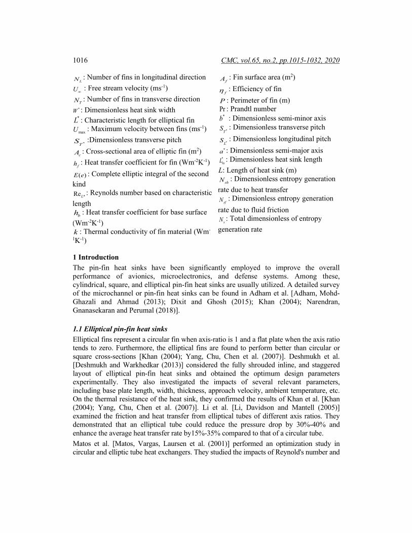
Figure 5: Dimensionless EGR due to heat transfer in terms of Reynolds number for different pitch ratios and axis ratio
In each case, Nsh decreases asymptotically with LRe . This is due to the increase in the maximum velocity between two fins. An increase in the velocity increases the heat transfer rate. Consequently, the thermal resistance decreases, and the corresponding EGR reduces. For the higher values of the pitch ratios and smaller values of axis ratios, Nsh is found to be higher. For the same values of the pitch ratios and the smaller values of axis ratios, the dimensionless EGR due to fluid friction, Nsf, is found to be the lowest (see Fig. 6). The EGR due to friction depends upon the maximum velocity between the fins. In other words, Nsf increases with an increase in LRe . The total dimensionless EGR combines the thermodynamic losses caused by both heat transfer and pressure drop in an elliptical pin-fin heat sink. It permits the combined effect of thermal resistance and pressure drop to be assessed through the simultaneous interaction with the heat sink.
Figure 6: Dimensionless EGR due to fluid friction in terms of Reynolds number for different pitch ratios and axis ratio
0 1000 2000 3000 4000 5000 6000
ReL
0
0.05
0.1
0.15
0.2
Nsh
SL
=ST=2,ϵ=0.5
SL
=ST=2.5,ϵ=0.5
SL
=ST=3,ϵ=0.5
SL
=ST=2,ϵ=0.1
SL
=ST=2.5,ϵ=0.1
SL
=ST=3,ϵ=0.1
ɣ=4
0 1000 2000 3000 4000 5000 6000
ReL
0
0.05
0.1
0.15
0.2
Nsf
SL
=ST=2,ϵ=0.5
SL
=ST=2.5,ϵ=0.5
SL
=ST=3,ϵ=0.5
SL
=ST=2,ϵ=0.1
SL
=ST=2.5,ϵ=0.1
SL
=ST=3,ϵ=0.1
ɣ=4

1026 CMC, vol.65, no.2, pp.1015-1032, 2020
The behavior of the dimensionless minimum entropy generation rates Ns, Nsh, and Ns can be observed in Figs. 7-9 for different values of aspect ratio γ dimensionless longitudinal pitch SL* and dimensionless transverse pitch ST* respectively. The variation of total dimensionless EGR versus Reynolds number is depicted in Fig. 7 for different values of aspect and pitch ratios. For each aspect and pitch ratio, a minimum value of Ns exists that shows the optimal values of LRe . This minimum value of Ns decreases with the aspect ratio for lower pitch ratios but increases for higher pitch ratios. This is because the Reynolds number depends upon the velocity in the minimum area. The total dimensionless EGR decreases with an increasing transverse pitch ratio due to a decrease in the velocity. Fig. 8 shows the variation of dimensionless EGR due to heat transfer versus Reynolds number. As expected, Nsh is decreasing with increasing LRe due to heat transfer from the surface. As the transverse spacing decreases, the temperature gradients decrease, and as a result, Nsh decreases. No significant effect of the aspect ratio on Nsh can be observed. On the other side, EGR due to fluid friction Nsf increases with LRe due to higher velocity gradients. As the transverse spacing decreases and aspect ratio increases, Nsf increases and becomes dominant at higher LRe . For each aspect ratio and pitch ratio, a minimum EGR exists, which specifies the optimum values of the design parameters. The optimum results of two-parameter optimization for the inline arrangement are summarized in Tab. 2.
Figure 7: Dimensionless EGR in terms of Reynolds number for different pitch and aspect ratios
Figure 8: Dimensionless EGR due to heat transfer in terms of Reynolds number for different pitch ratios and aspect ratio
1000 2000 3000 4000 5000 6000
ReL
0
0.02
0.04
0.06
0.08
0.1
0.12
0.14
0.16
0.18
0.2
N s
ɣ=2,SL
=ST
=3
ɣ=6,SL
=ST
=3
ɣ=8,SL
=ST
=3
ɣ=2,SL
=ST
=1.5
ɣ=6,SL
=ST
=1.5
ɣ=8,SL
=ST
=1.5
1000 2000 3000 4000 5000 6000
ReL
0
0.02
0.04
0.06
0.08
0.1
0.12
0.14
0.16
0.18
0.2
Nsh
ɣ=4,SL
=ST
=3
ɣ=6,SL
=ST
=3
ɣ=8,SL
=ST
=3
ɣ=4,SL
=ST
=1.5
ɣ=6,SL
=ST
=1.5
ɣ=8,SL
=ST
=1.5
ϵ=0.2

Second Law Analysis and Optimization of Elliptical Pin Fin Heat 1027
Table 2: The optimum results of two-parameter optimization for the inline arrangement ReL* Ns Nsh Nsf SL*=ST* γ ϵ 1899 0.0665 0.0358 0.0307 2 4 0.1 2690 0.0572 0.0304 0.0268 2.5 4 0.1 3323 0.0523 0.0302 0.0221 3 4 0.1 1741 0.0530 0.0260 0.0270 2 4 0.5 2373 0.0461 0.0244 0.0217 2.5 4 0.5 3165 0.0437 0.0234 0.0203 3 4 0.5 949 0.0970 0.0499 0.0471 1.5 4 0.5 949 0.1174 0.0468 0.0706 1.5 6 0.2 633 0.1367 0.0778 0.0589 1.5 8 0.2 3164 0.0479 0.0276 0.0203 3 4 0.2 2848 0.0488 0.0320 0.0168 3 6 0.2 2531 0.0514 0.0377 0.0137 3 8 0.2
Figure 9: Dimensionless EGR due to fluid friction in terms of Reynolds number for different pitch ratios and aspect ratio
Figure 10: Best performance of FFA in terms of Ns values
In the next step, the FFA will determine the minimum value of Ns for the selected Elliptical Pin-fin heat sink. Each time, 20 randomly generated feasible initial solutions, 50 iterations, * 1γ = and α=0.2 are used. According to the best results, Fig. 10 represents
ReL
0 1000 2000 3000 4000 5000 6000
N sf
0
0.2
0.4
0.6
0.8
ɣ=4,SL
=ST
=3
ɣ=6,SL
=ST
=3
ɣ=8,SL
=ST
=3
ɣ=4,SL
=ST
=1.5
ɣ=6,SL
=ST
=1.5
ɣ=8,SL
=ST
=1.5
ϵ=0.2
0 5 10 15 20 25 30 35 40 45 50
Iteration
0.041
0.042
0.043
0.044
0.045
0.046
0.047
0.048
0.049
0.05
N S
Ns Value
Best Ns Value

1028 CMC, vol.65, no.2, pp.1015-1032, 2020
the optimum values of the objective function Ns. During each iteration, the algorithm maintains the minimum value of Ns and searches for a new minimum value. If the new Ns value is not the optimal value, then FFA will keep the previous minimal Ns value. To validate the current results of FFA for the minimization of dimensionless EGR, we compared our findings from FFA with the outcome of using PPA (see Fig. 11). Although the results showed that FFA converged faster than PPA in finding a global solution, FFA found the optimal solution.
Figure 11: Best performance of PPA and FFA for Ns values
Fig. 12 demonstrates the relationship between Ns, Nsf, and Nsh during updating using FFA. It shows that the optimal values of Nsf are in the interval [0.01, 0.02], and the optimal values of Nsh are in the interval [0.041, 0.042]. To see the performance and behavior of searching fireflies for the optimal solution, Fig. 13(a) represents the location of the fireflies of (U∞
and∈) at the beginning of the search. In this figure, fireflies spread out over a large area within the search space. In contrast, Fig. 13(b) represents the location of the fireflies at the end of the search, as the search area has shrunk considerably due to the FFA technique. In addition, Fig. 13(b) indicates that fireflies are looking for the best parameter values in a clustered group. Tab. 3 represents the best values of Ns with the corresponding values the design parameters N, U∞
,∈ , and γ .
Figure 12: Relationship between Ns, Nsf, and Nsh during updating using FFA
0 5 10 15 20 25 30 35 40 45 50
Iteration
0.04
0.042
0.044
0.046
0.048
0.05
0.052
N S
PPA
FFA
0.060.05
0.04
Ns
f
0.030.02
0.010.048
0.046
Ns
0.044
0.042
0
0.01
0.03
0.04
0.02
Ns
h

Second Law Analysis and Optimization of Elliptical Pin Fin Heat 1029
Figure 13: (a) Initial fireflies’ position before training, (b) Final fireflies’ position after training
Table 3: Optimum values of design parameters corresponding to minimum Ns γ U∞ SL* ST* ϵ N Ns 4 0.1090 3 2.583 0.5000 16 0.0417 4 0.1459 3 2.6925 0.4851 16 0.0418 4 0.1 3 2.5 0.5000 20 0.0439
5 Conclusions Mathematical models are developed for the thermal resistance, hydraulic resistance, and entropy generation rate in the heat sink. These models are based on mass, energy, and entropy balance. The entropy generation rate (EGR) encompasses the effects of thermal resistance and pressure drop. FFA was employed the first time successfully to find the minimum possible values of the total dimensionless entropy generation rate (Ns) for different parameters. It has been proved to be powerful in solving many optimization problems. Approach velocity (U∞), the dimensionless longitudinal and transverse pitch ratios, the axis ratio ϵ, and the aspect ratio γ are the design parameters of our objective function Ns. It is shown that FFA converges after 7 iterations whereas, PPA converges after 13 iterations. It is observed that Nsh decreases whereas Nsf increases with ReL. For larger pitch ratios, Nsh is found to be higher, whereas, Nsf is higher for smaller pitch ratios. The total entropy generation rate is found to be higher for smaller pitch ratios. For the higher performance of an elliptical pin-fin heat sink, the lower axis ratio and higher pitch ratios are preferred. The results of the optimization are also reported in Tab. 3. The results show that both thermal resistance and pressure drop can be simultaneously optimized using FFA. The optimal value of Ns is found to be 0.0417. The corresponding optimum design parameters are: U∞=0.109 m/s, SL*=3, ST*=2.583, ϵ =0.5, and N=16. It is demonstrated that the minimum EGR decreases with increasing dimensionless pitch ratios and decreasing the axis ratios.

1030 CMC, vol.65, no.2, pp.1015-1032, 2020
Funding Statement: This research is supported by the Deanship of Scientific Research/ Saudi Electronic University [Research Number: 7638-HS-2019-1-1-S]. Initials of authors who received the grant: N. N. Hamadneh; W. A. Khan.
Conflicts of Interest: The authors declare that they have no conflicts of interest to report regarding the present study.
References Adham, A. M.; Mohd-Ghazali, N.; Ahmad, R. (2013): Thermal and hydrodynamic analysis of microchannel heat sinks: a review. Renewable and Sustainable Energy Reviews, vol. 21, pp. 614-622. Baruah, M.; Borah, M.; Das, H. (2016): The effect of major and minor axis of elliptical shape pin fins on heat transfer and pressure drop characteristics. Indiana University of Pennsylvania-Journal of Mechanical Engineering, vol. 9, no. 2, pp. 20-36. Bejan, A. (1996): Entropy generation minimization: The new thermodynamics of finite-size devices and finite-time processes. Journal of Applied Physics, vol. 79, no. 3, pp. 1191-1218. Deshmukh, P.; Warkhedkar, R. (2013): Thermal performance of elliptical pin fin heat sink under combined natural and forced convection. Experimental Thermal and Fluid Science, vol. 50, pp. 61-68. Dixit, T.; Ghosh, I. (2015): Review of micro-and mini-channel heat sinks and heat exchangers for single phase fluids. Renewable and Sustainable Energy Reviews, vol. 41, pp. 1298-1311. Fister, I.; Fister Jr, I.; Yang, X. S.; Brest, J. (2013): A comprehensive review of firefly algorithms. Swarm and Evolutionary Computation, vol. 13, pp. 34-46. Hamadneh, N. (2020): Dead sea water levels analysis using artificial neural networks and firefly algorithm. International Journal of Swarm Intelligence Research, vol. 11, no. 3, pp. 1-11. Hamadneh, N. N.; Khan, W. A.; Khan, I.; Alsagri, A. S. (2019): Modeling and optimization of gaseous thermal slip flow in rectangular microducts using a particle swarm optimization algorithm. Symmetry, vol. 11, no. 4, pp. 1-13. Hamadneh, N.; Khan, W. A.; Sathasivam, S.; Ong, H. C. (2013): Design optimization of pin fin geometry using particle swarm optimization algorithm. PLoS One, vol. 8, no. 5, e66080. Hamadneh, N.; Khan, W.; Tilahun, S. (2018): Optimization of microchannel heat sinks using prey-predator algorithm and artificial neural networks. Machines, vol. 6, no. 2, pp. 1-26. Kadri, M.; Khan, W.; Ali, Q. (2013): Optimization of microchannel heat sinks using genetic algorithms. Heat Transfer Engineering, vol. 34, no. 4, pp. 279-287. Khan, W. (2004): Modeling of Fluid Flow and Heat Transfer for Optimization of Pin-Fin Heat Sinks (Ph.D. Thesis). University of Waterloo, Canada.

Second Law Analysis and Optimization of Elliptical Pin Fin Heat 1031
Khan, W. A.; Hamadneh, N. N.; Tilahun, S. L.; Ngnotchouye, J. M. (2016): A review and comparative study of firefly algorithm and its modified versions. Optimization Algorithms-Methods and Applications. InTech, UK. Khan, W. A.; Yovanovich, M.; Culham, J. (2006): Optimization of microchannel heat sinks using entropy generation minimization method. Twenty-Second Annual IEEE Semiconductor Thermal Measurement and Management Symposium, pp. 78-86. Kim, H. M.; Moon, M. A.; Kim, K. Y. (2011): Multi-objective optimization of a cooling channel with staggered elliptic dimples. Energy, vol. 36, no. 5, pp. 3419-3428. Li, Z.; Davidson, J.; Mantell, S. (2005): Numerical simulation of flow field and heat transfer of streamlined cylinders in crossflow. ASME Summer Heat Transfer Conference, pp. 531-541. Matos, R.; Laursen, T.; Vargas, J.; Bejan, A. (2004): Three-dimensional optimization of staggered finned circular and elliptic tubes in forced convection. International Journal of Thermal Sciences, vol. 43, no. 5, pp. 477-487. Matos, R.; Vargas, J.; Laursen, T.; Bejan, A. (2004): Optimally staggered finned circular and elliptic tubes in forced convection. International Journal of Heat and Mass Transfer, vol. 47, no. 6-7, pp. 1347-1359. Matos, R.; Vargas, J.; Laursen, T.; Saboya, F. (2001): Optimization study and heat transfer comparison of staggered circular and elliptic tubes in forced convection. International Journal of Heat and Mass Transfer, vol. 44, no. 20, pp. 3953-3961. Mohanty, D. K. (2016): Application of firefly algorithm for design optimization of a shell and tube heat exchanger from economic point of view. International Journal of Thermal Sciences, vol. 102, pp. 228-238. Mohsin, S.; Maqbool, A.; Khan, W. A. (2009): Optimization of cylindrical pin-fin heat sinks using genetic algorithms. IEEE Transactions on Components and Packaging Technologies, vol. 32, no. 1, pp. 44-52. Narendran, G.; Gnanasekaran, N.; Perumal, D. A. (2018): A review on recent advances in microchannel heat sink configurations. Recent Patents on Mechanical Engineering, vol. 11, no. 3, pp. 190-215. Sahiti, N.; Lemouedda, A.; Stojkovic, D.; Durst, F.; Franz, E. (2006): Performance comparison of pin fin in-duct flow arrays with various pin cross-sections. Applied Thermal Engineering, vol. 26, no. 11-12, pp. 1176-1192. Sasmal, C. (2017): Effects of axis ratio, nanoparticle volume fraction, and its size on the momentum and heat transfer phenomena from an elliptic cylinder in water-based CuO nanofluids. Powder Technology, vol. 313, pp. 272-286. Seyf, H. R.; Layeghi, M. (2010): Numerical analysis of convective heat transfer from an elliptic pin fin heat sink with and without metal foam insert. Journal of Heat Transfer, vol. 132, no. 7, pp. 1-9. Singh, M.; Patel, R.; Neema, D. (2019): Robust tuning of excitation controller for stability enhancement using multi-objective metaheuristic Firefly algorithm. Swarm and Evolutionary Computation, vol. 44, pp. 136-147.
1032 CMC, vol.65, no.2, pp.1015-1032, 2020
Tilahun, S. L.; Ngnotchouye, J. M. T.; Hamadneh, N. N. (2017): Continuous versions of firefly algorithm: a review. Artificial Intelligence Review, pp. 1-48. Tilahun, S. L.; Ong, H. C.; Ngnotchouye, J. M. T. (2016): Extended prey-predator algorithm with a group hunting scenario. Advances in Operations Research, vol. 2016, pp. 1-14. Yang, K. S.; Chu, W. H.; Chen, Y.; Wang, C. C. (2007): A comparative study of the airside performance of heat sinks having pin fin configurations. International Journal of Heat and Mass Transfer, vol. 50, no. 23-24, pp. 4661-4667. Yang, X. S. (2013): Cuckoo Search and Firefly Algorithm. Theory and Applications. Springer. Zhao, J.; Hu, Z.; Xiong, B.; Yang, L.; Li, K. (2020): Modelling and optimization of packet forwarding performance in software-defined WAN. Future Generation Computer Systems, vol. 106, pp. 412-425.


![[XLS] · Web view91" X 58" ELLIPTICAL PIPE 02582 91" X 58" ELLIPTICAL CONC. PIPE 02630 98" X 63" ELLIPTICAL PIPE 02632 98" X 63" ELLIPTICAL CONC. PIPE 02680 106" X 68" ELLIPTICAL](https://img.pdfslide.us/doc/110x75/5ae3d8767f8b9a5d648e7b83/xls-view91-x-58-elliptical-pipe-02582-91-x-58-elliptical-conc-pipe-02630-98-x.jpg)