Embed Size (px)
Citation preview
Second harmonic generation in galliumphosphide photonic crystal nanocavities
with ultralow continuous wave pumppower
Kelley Rivoire1∗, Ziliang Lin1, Fariba Hatami2, W. Ted Masselink2,and Jelena Vuckovic1
1E. L. Ginzton Laboratory, Stanford University, Stanford, CA 94305-4085, U.S.A.2Department of Physics, Humboldt University, D-10115, Berlin, Germany
Abstract: We demonstrate second harmonic generation in photoniccrystal nanocavities fabricated in the semiconductor gallium phosphide.We observe second harmonic radiation at 750 nm with input pow-ers of only nanowatts coupled to the cavity and conversion efficiencyPout/P2
in,coupled = 430%/W. The large electronic band gap of GaP minimizesabsorption loss, allowing efficient conversion. Our results are promising forintegrated, low-power light sources and on-chip reduction of input power inother nonlinear processes.
© 2009 Optical Society of America
OCIS codes: (190.4390) Nonlinear optics, integrated optics; (350.4238) Nanophotonics andphotonic crystals; (190.4400) Nonlinear optics, materials; (230.5750) Resonators; (130.3120 )Integrated optics devices.
References and links1. O. Levi, T. J. Pinguet, T. Skauli, L. A. Eyres, K. R. Parameswaran, J. J. S. Harris, M. M. Fejer, T. J. Kulp,
S. E. Bisson, B. Gerard, E. Lallier, and L. Becouarn, “Difference frequency generation of 8-µm radiation inorientation-patterned GaAs,” Opt. Lett. 27, 2091–2093 (2002).
2. P. S. Kuo, K. L. Vodopyanov, M. M. Fejer, D. M. Simanovskii, X. Yu, J. S. Harris, D. Bliss, and D. Weyburne,“Optical parametric generation of a mid-infrared continuum in orientation-patterned GaAs,” Opt. Lett. 31, 71–73(2006).
3. K. L. Vodopyanov, M. M. Fejer, X. Yu, J. S. Harris, Y.-S. Lee, W. C. Hurlbut, V. G. Kozlov, D. Bliss, andC. Lynch, “Terahertz-wave generation in quasi-phase-matched GaAs,” Appl. Phys. Lett. 89, 141119 (2006).
4. I. Shoji, T. Kondo, A. Kitamoto, M. Shirane, and R. Ito, “Absolute scale of second-order nonlinear-optical coef-ficients,” J. Opt. Soc. Am. B 14, 2268–2294 (1997).
5. L. A. Eyres, P. J. Tourreau, T. J. Pinguet, C. B. Ebert, J. S. Harris, M. M. Fejer, L. Becouarn, B. Gerard, andE. Lallier, “All-epitaxial fabrication of thick, orientation-patterned GaAs films for nonlinear optical frequencyconversion,” Appl. Phys. Lett. 79, 904–906 (2001).
6. L. Scaccabarozzi, M. M. Fejer, Y. Huo, S. Fan, X. Yu, and J. S. Harris, “Enhanced second-harmonic generationin AlGaAs/AlxOy tightly confining waveguides and resonant cavities,” Opt. Lett. 31, 3626–3628 (2006).
7. Z. Yang, P. Chak, A.D.. Bristow, H.M. van Driel, R. Iyer, J.S. Aitchison, A.L. Smirl, and J.E. Sipe, “Enhancedsecond-harmonic generation in AlGaAs microring resonators,” Opt. Lett. 32, 826–828 (2007).
8. M. Liscidini, A. Locatelli, L.C. Andreani, C. De Angelis, “Maximum-Exponent Scaling Behavior of OpticalSecond-Harmonic Generation in Finite Multilayer Photonic Crystals,” Phys. Rev. Lett. 99, 053907 (2007).
9. W. J. Kozlovsky, C. Nabors, and R. L. Byer, “Efficient second harmonic generation of a diode-laser-pumped CWNd : YAG laser using monolithic MgO : LiNbO3 external resonant cavities,” IEEE J. Quantum Electron. 28,2631–2654 (1988).
10. A. Rodriguez, M. Soljacic, J. D. Joannopoulos, and S. G. Johnson, “χ (2) and χ (3) harmonic generation at acritical power in inhomogeneous doubly resonant cavities,” Opt. Express 15, 7303–7318 (2007).
#119071 - $15.00 USD Received 26 Oct 2009; revised 18 Nov 2009; accepted 19 Nov 2009; published 24 Nov 2009
(C) 2009 OSA 7 December 2009 / Vol. 17, No. 25 / OPTICS EXPRESS 22609
11. A. Hayat and M. Orenstein, “Photon conversion processes in dispersive microcavities: Quantum-field model,”Phys. Rev. A 77, 013830 (2008).
12. M. Liscidini and L. C. Andreani, “Highly efficient second-harmonic generation in doubly resonant planar micro-cavities,” Appl. Phys. Lett. 85, 1883–1885 (2004).
13. T. Carmon and K. Vahala, “Visible continuous emission from a silica microphotonic device by third-harmonicgeneration,” Nat. Phys. 3, 430–435 (2007).
14. M. W. McCutcheon, J. F. Young, G. W. Rieger, D. Dalacu, S. Frederick, P. J. Poole, and R. L. Williams, “Ex-perimental demonstration of second-order processes in photonic crystal microcavities at submilliwatt excitationpowers,” Phys. Rev. B 76, 245104 (2007).
15. B. Corcoran, C. Monat, C. Grillet, D. Moss, B. Eggleton, T. White, L. O’Faolain, and T. Krauss, “Green lightemission in silicon through slow-light enhanced third-harmonic generation in photonic-crystal waveguides,” Nat.Photon. 3, 206–210 (2009).
16. Y. Akahane, T. Asano, B. Song, and S. Noda, “High-Q photonic nanocavity in a two-dimensional photoniccrystal,” Nature 425, 944–947 (2003).
17. Y. Zhang, M. W. McCutcheon, I. B. Burgess, and M. Loncar, “Ultra-high-Q TE/TM dual-polarized photoniccrystal nanocavities,” Opt. Lett. 34, 2694–2696 (2009).
18. K. Rivoire, A. Faraon, and J. Vuckovic, “Gallium phosphide photonic crystal nanocavities in the visible,” Appl.Phys. Lett. 93, 063103 (2008).
19. M. Toishi, D. Englund, A. Faraon, and J. Vuckovic, “High-brightness single photon source from a quantum dotin a directional-emission nanocavity,” Opt. Express 17, 14618–14626 (2009).
20. A. Faraon, E. Waks, D. Englund, I. Fushman, and J. Vuckovic, “Efficient photonic crystal cavity-waveguidecouplers,” Appl. Phys. Lett. 90, 073102 (2007).
1. Introduction
III-V semiconductors such as GaAs and GaP are considered promising candidates for nonlinearoptical devices [1–3] because of their large second order nonlinearity [4], transparency over awide wavelength range (870 nm-17 µm for GaAs and 550 nm-11 µm for GaP), and ease ofintegration with semiconductor processing. The cubic symmetry of the zincblende lattice ofIII-V semiconductors, however, does not exhibit birefringence, so achieving phase matching ofthe two different frequencies typically requires employing quasi-phase matching techniques oran additional birefringent material [5–8].
In addition to the challenges posed by phase matching, nonlinear optical devices are alsoconstrained by the bulky, macroscopic resonant cavities typically used to enhance conversionefficiency and reduce the required input power [9]. High quality factor microcavities have thepotential to achieve similar conversion efficiencies with a vastly reduced size, and could beintegrated with nanophotonic technology. In these microcavities, the phase matching condi-tion is satisfied by the spatial overlap between the fundamental and second harmonic fieldpatterns [10–12]. Experimentally, this resonant enhancement has been demonstrated in silicamicrodisks [13], where green third harmonic radiation was observable with hundreds of mi-crowatts incident continuous wave IR power. Enhanced second harmonic generation in photoniccrystal cavities [14] and third harmonic generation in photonic crystal waveguides [15] havealso been demonstrated. However, these experiments suffered from poor conversion efficiency,in part because the second harmonic was above the band gap of the employed semiconductorand therefore strongly absorbed in it (where efficiency is defined as the ratio of the output sec-ond harmonic to the coupled input power at 1550 nm, third harmonic Pout/Pin,coupled = 5×10⁻¹⁰
for peak Pin = 1W [15]; second harmonic Pout/Pin = 10−13 for CW Pin = 300µW [14]). In thispaper, we show that photonic crystal nanocavities resonant with the pump wavelength can beused to generate second harmonic radiation with input power orders of magnitude smaller thanpreviously demonstrated.
2. Cavity design
The experiment is described in Fig. 1(a). Our resonator is a modified linear three hole de-fect photonic crystal cavity [16]. A scanning electron microscope (SEM) image is shown in
#119071 - $15.00 USD Received 26 Oct 2009; revised 18 Nov 2009; accepted 19 Nov 2009; published 24 Nov 2009
(C) 2009 OSA 7 December 2009 / Vol. 17, No. 25 / OPTICS EXPRESS 22610
CCD
HWP
HWP
NPBSOLSample
Polarizer
Laser
PBS
PD
MonochromatorSPF
720 730 740 750 760 7700
10
20
30
40
50
Wavelength [nm]
Cou
nts
a.
b. c.
Camera
FlipMirror
Polarizer
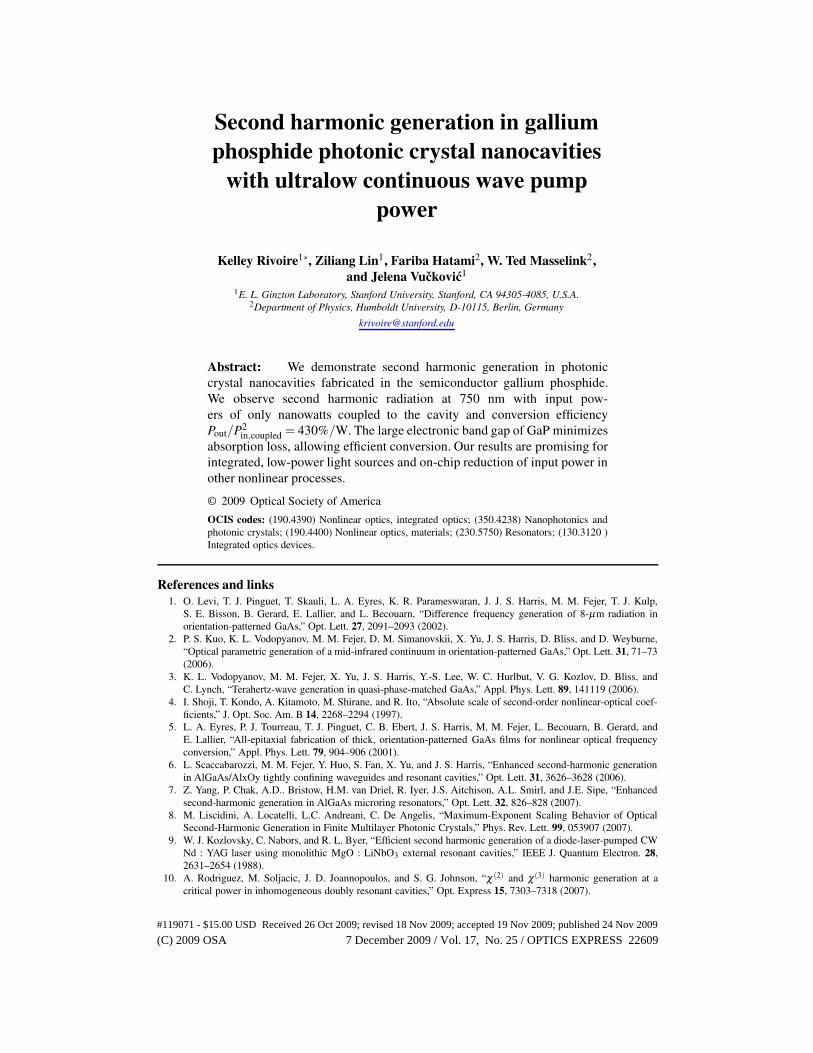
Fig. 1. (a) Confocal microscope-based setup for second harmonic generation. HWP: halfwave plate, NPBS: nonpolarizing beamsplitter, OL: objective lens, PBS: polarizing beam-splitter, SPF: short pass filter, PD: photodiode. The incident light traces the red line intothe cavity sample. The second harmonic light follows the blue line into the spectrometer,photodiode, or camera. The polarization of the incident light is controlled by the polarizerand HWP; the polarization of the second harmonic radiation is measured using HWP andPBS. (b) SEM image of a fabricated structure. Scale bar indicates 1 µm. (c) Spectrum ofgenerated second harmonic light with 8 nW power at 1497.4 nm coupled to the cavity (160nW incident).
Fig. 1(b). A tunable infrared laser (Agilent 81680A) with wavelength range around 1500 nm atnormal incidence is spatially aligned to the cavity location and spectrally aligned to the cavityresonance; the laser polarization is also aligned to match that of the cavity mode. In this con-figuration, enhanced second harmonic radiation is generated; this radiation is either analyzedby a spectrometer, measured by a femtowatt photodetector, or imaged onto a camera. A secondharmonic spectrum with 8 nW power coupled to the cavity (160 nW incident on the sample) isshown in Fig. 1(c). The electronic band gap of GaP prevents both absorption of the harmonicradiation at 750 nm and two photon absorption at the fundamental wavelength 1500 nm. Thesamples were grown by gas-source molecular beam epitaxy on a (100)-oriented GaP wafer. A160 nm thick GaP membrane was grown on the top of a 1 µm thick sacrificial AlGaP layer.Structures were fabricated with e-beam lithography and etching, as described in [18]. The pho-tonic crystal cavities are three hole linear defects [16] with lattice constant a = 500− 560nm,hole radius r/a ≈ 0.2− 0.25, and slab thickness d/a ≈ 0.3. We use a perturbation design forour photonic crystal cavities [19] to increase the coupling efficiency between the cavity andobjective lens.
To efficiently radiate power at the second harmonic, the field patterns at the fundamental andsecond harmonic frequency must have constructive overlap. In our experiment, the fundamentalfrequency is set to that of the cavity mode, which dictates the field pattern at this frequency.The second harmonic frequency is matched to a higher order photonic band edge mode, which
#119071 - $15.00 USD Received 26 Oct 2009; revised 18 Nov 2009; accepted 19 Nov 2009; published 24 Nov 2009
(C) 2009 OSA 7 December 2009 / Vol. 17, No. 25 / OPTICS EXPRESS 22611
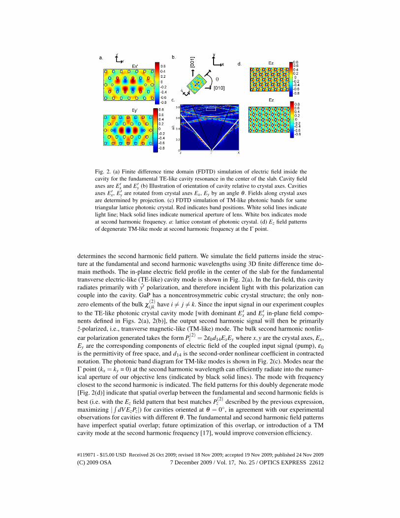
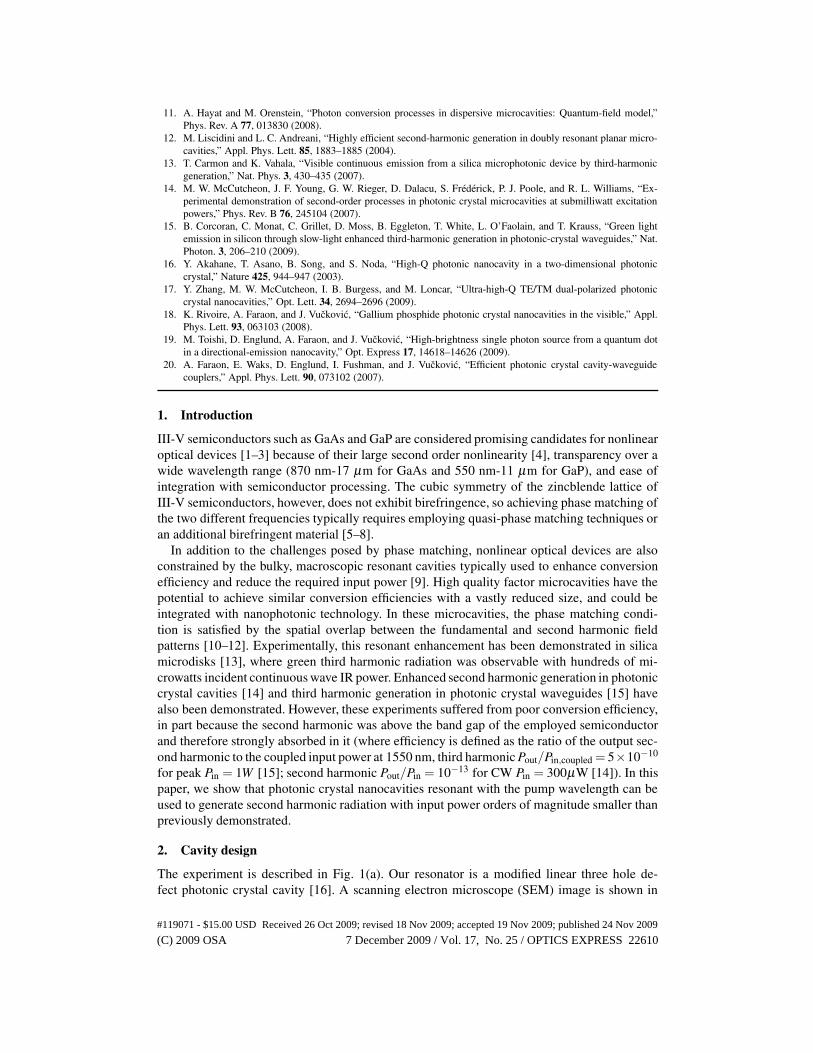
Fig. 2. (a) Finite difference time domain (FDTD) simulation of electric field inside thecavity for the fundamental TE-like cavity resonance in the center of the slab. Cavity fieldaxes are E ′
x and E ′y (b) Illustration of orientation of cavity relative to crystal axes. Cavities
axes E ′x, E ′
y are rotated from crystal axes Ex, Ey by an angle θ . Fields along crystal axesare determined by projection. (c) FDTD simulation of TM-like photonic bands for sametriangular lattice photonic crystal. Red indicates band positions. White solid lines indicatelight line; black solid lines indicate numerical aperture of lens. White box indicates modeat second harmonic frequency. a: lattice constant of photonic crystal. (d) Ez field patternsof degenerate TM-like mode at second harmonic frequency at the Γ point.
determines the second harmonic field pattern. We simulate the field patterns inside the struc-ture at the fundamental and second harmonic wavelengths using 3D finite difference time do-main methods. The in-plane electric field profile in the center of the slab for the fundamentaltransverse electric-like (TE-like) cavity mode is shown in Fig. 2(a). In the far-field, this cavityradiates primarily with y′ polarization, and therefore incident light with this polarization cancouple into the cavity. GaP has a noncentrosymmetric cubic crystal structure; the only non-zero elements of the bulk χ (2)
i jk have i 6= j 6= k. Since the input signal in our experiment couplesto the TE-like photonic crystal cavity mode [with dominant E ′
x and E ′y in-plane field compo-
nents defined in Figs. 2(a), 2(b)], the output second harmonic signal will then be primarilyz-polarized, i.e., transverse magnetic-like (TM-like) mode. The bulk second harmonic nonlin-ear polarization generated takes the form P(2)
z = 2ε0d14ExEy where x,y are the crystal axes, Ex,Ey are the corresponding components of electric field of the coupled input signal (pump), ε0is the permittivity of free space, and d14 is the second-order nonlinear coefficient in contractednotation. The photonic band diagram for TM-like modes is shown in Fig. 2(c). Modes near theΓ point (kx = ky = 0) at the second harmonic wavelength can efficiently radiate into the numer-ical aperture of our objective lens (indicated by black solid lines). The mode with frequencyclosest to the second harmonic is indicated. The field patterns for this doubly degenerate mode[Fig. 2(d)] indicate that spatial overlap between the fundamental and second harmonic fields isbest (i.e. with the Ez field pattern that best matches P(2)
z described by the previous expression,maximizing |
∫dVEzPz|) for cavities oriented at θ = 0◦, in agreement with our experimental
observations for cavities with different θ . The fundamental and second harmonic field patternshave imperfect spatial overlap; future optimization of this overlap, or introduction of a TMcavity mode at the second harmonic frequency [17], would improve conversion efficiency.
#119071 - $15.00 USD Received 26 Oct 2009; revised 18 Nov 2009; accepted 19 Nov 2009; published 24 Nov 2009
(C) 2009 OSA 7 December 2009 / Vol. 17, No. 25 / OPTICS EXPRESS 22612
1485 1485.2 1485.4 1485.6 1485.8 14860
0.2
0.4
0.6
0.8
1
Wavelength [nm]
Nor
mal
ized
Cou
nts
datafit
a.
1485 1485.2 1485.4 1485.6 1485.8 14860
0.2
0.4
0.6
0.8
1
Scanning Laser Wavelength [nm]
Nor
mal
ized
Pea
k S
H C
ount
s datafit
b.
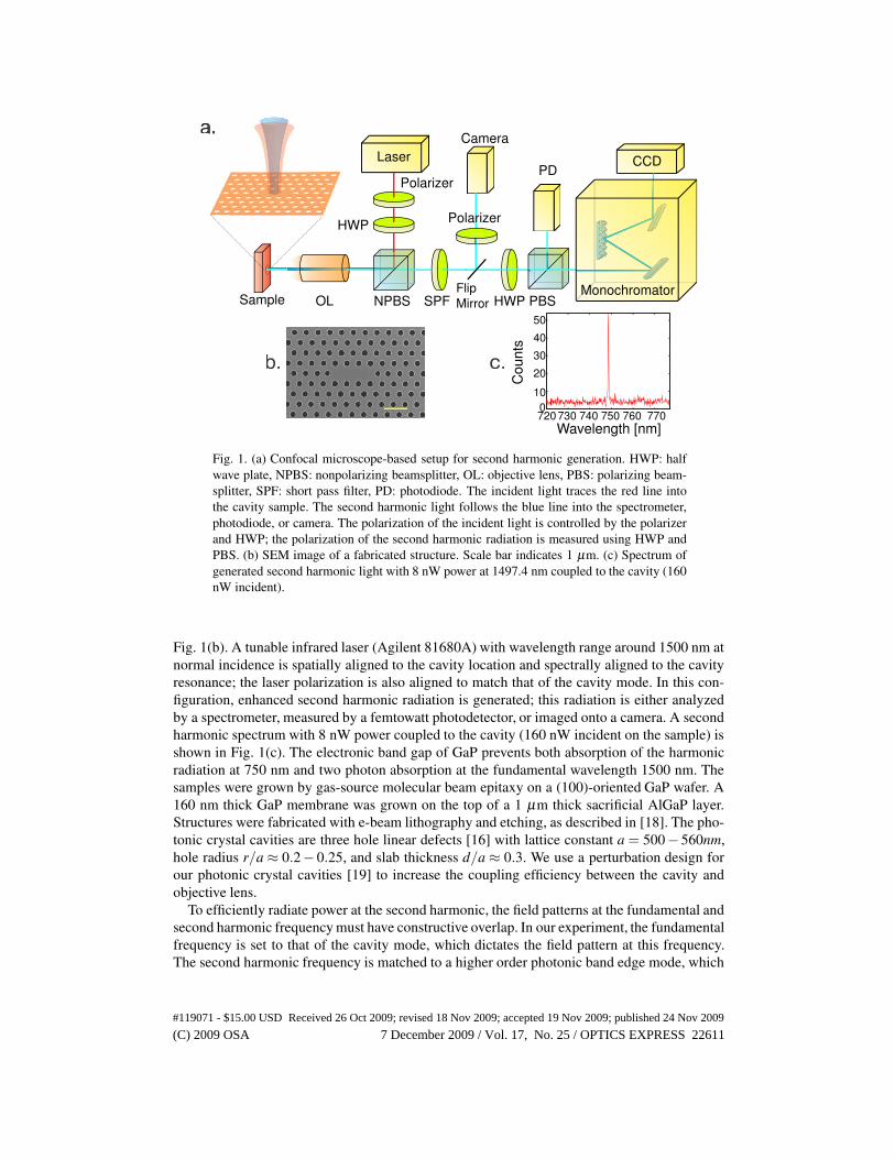
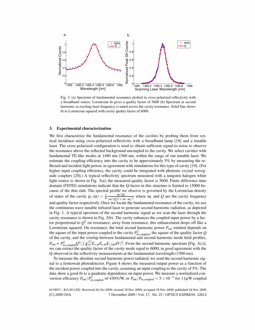
Fig. 3. (a) Spectrum of fundamental resonance probed in cross-polarized reflectivity witha broadband source. Lorentzian fit gives a quality factor of 5600 (b) Spectrum at secondharmonic as exciting laser frequency is tuned across the cavity resonance. Solid line showsfit to Lorentzian squared with cavity quality factor of 6000.
3. Experimental characterization
We first characterize the fundamental resonance of the cavities by probing them from ver-tical incidence using cross-polarized reflectivity with a broadband lamp [18] and a tunablelaser. The cross-polarized configuration is used to obtain sufficient signal-to-noise to observethe resonance above the reflected background uncoupled to the cavity. We select cavities withfundamental TE-like modes at 1480 nm-1560 nm, within the range of our tunable laser. Weestimate the coupling efficiency into the cavity to be approximately 5% by measuring the re-flected and incident light power, in agreement with simulations for this type of cavity [19]. (Forhigher input coupling efficiency, the cavity could be integrated with photonic crystal waveg-uide couplers [20].) A typical reflectivity spectrum measured with a tungsten halogen whitelight source is shown in Fig. 3(a); the measured quality factor is 5600. Finite difference timedomain (FDTD) simulations indicate that the Q-factor in this structure is limited to 15000 be-cause of the thin slab. The spectral profile we observe is governed by the Lorentzian densityof states of the cavity ρc (ω) = 1
πω/2Q
(ω/2Q)2+(ω−ωc)2 where ωc and Q are the cavity frequency
and quality factor respectively. Once we locate the fundamental resonance of the cavity, we usethe continuous wave tunable infrared laser to generate second harmonic radiation, as depictedin Fig. 1. A typical spectrum of the second harmonic signal as we scan the laser through thecavity resonance is shown in Fig. 3(b). The cavity enhances the coupled input power by a fac-tor proportional to Q2 on resonance; away from resonance, this enhancement drops off like aLorentzian squared. On resonance, the total second harmonic power Pout emitted depends onthe square of the input power coupled to the cavity P2
in,coupled, the square of the quality factor Qof the cavity, and the overlap between fundamental and second harmonic mode field profiles,Pout ∝ P2
in,coupledQ2|∫
χ(2)xyz Ex,ω Ey,ω Ez,2ω dV |2. From the second harmonic spectrum [Fig. 3(c)],
we can extract the quality factor of the cavity mode equal to 6000, in good agreement with theQ observed in the reflectivity measurements at the fundamental wavelength (1500 nm).
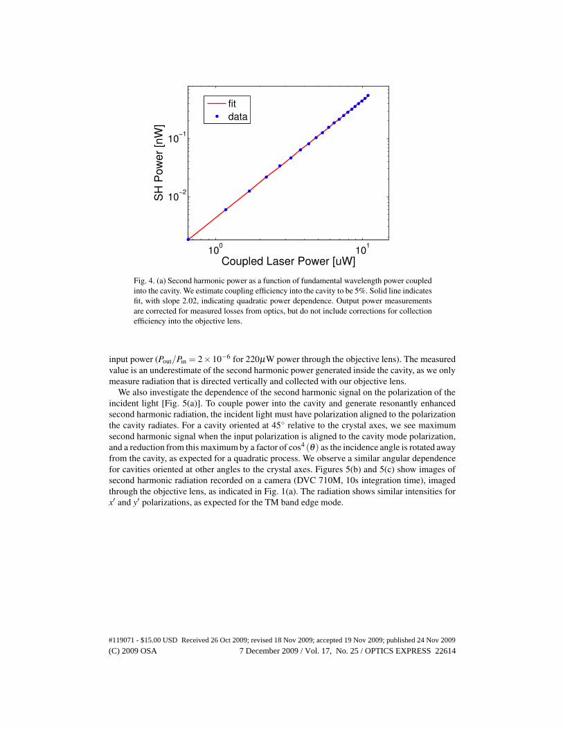
To measure the absolute second harmonic power radiated, we send the second harmonic sig-nal to a femtowatt photodetector. Figure 4 shows the measured output power as a function ofthe incident power coupled into the cavity, assuming an input coupling to the cavity of 5%. Thedata show a good fit to a quadratic dependence on input power. We measure a normalized con-version efficiency Pout/P2
in,coupled of 430%/W, or Pout/Pin,coupled = 5×10⁻⁵ for 11µW coupled
#119071 - $15.00 USD Received 26 Oct 2009; revised 18 Nov 2009; accepted 19 Nov 2009; published 24 Nov 2009
(C) 2009 OSA 7 December 2009 / Vol. 17, No. 25 / OPTICS EXPRESS 22613
100
101
10−2
10−1
Coupled Laser Power [uW]
SH
Pow
er [n
W]
fitdata
Fig. 4. (a) Second harmonic power as a function of fundamental wavelength power coupledinto the cavity. We estimate coupling efficiency into the cavity to be 5%. Solid line indicatesfit, with slope 2.02, indicating quadratic power dependence. Output power measurementsare corrected for measured losses from optics, but do not include corrections for collectionefficiency into the objective lens.
input power (Pout/Pin = 2×10⁻⁶ for 220µW power through the objective lens). The measuredvalue is an underestimate of the second harmonic power generated inside the cavity, as we onlymeasure radiation that is directed vertically and collected with our objective lens.
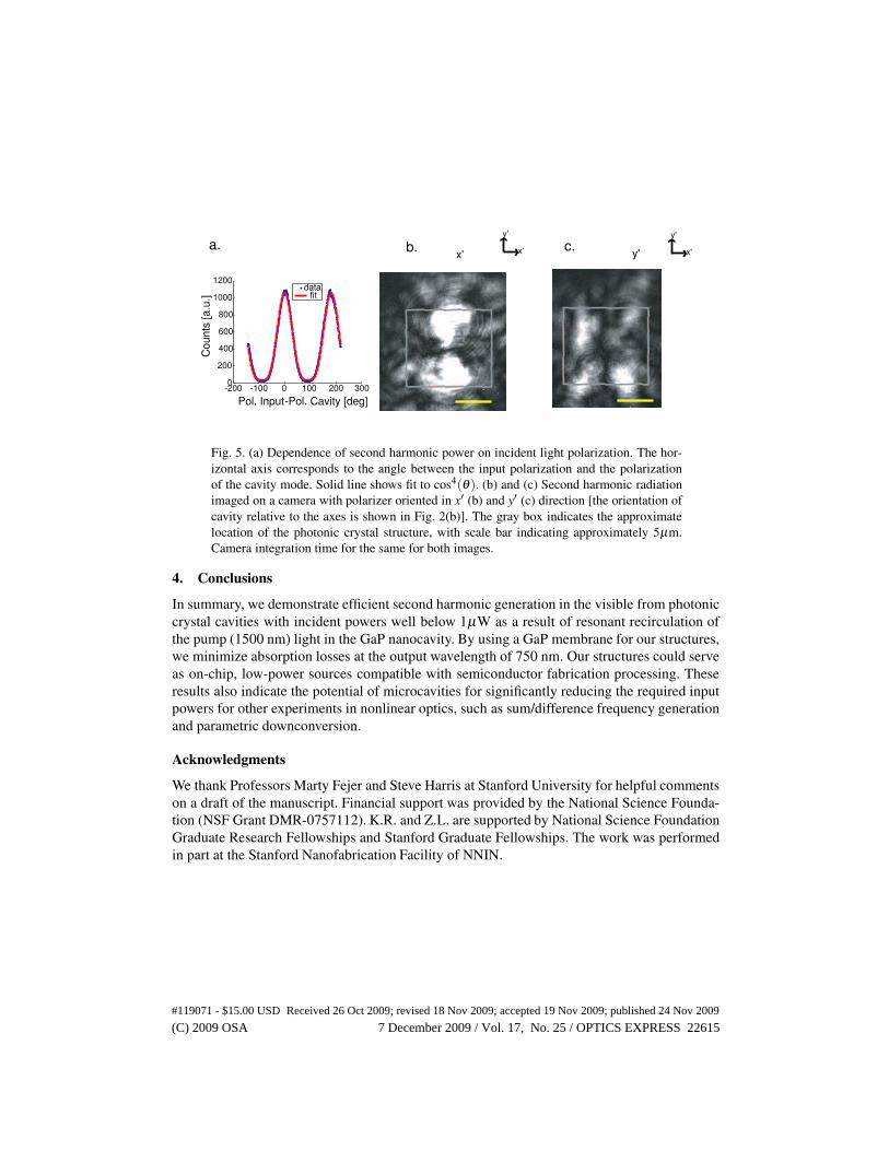
We also investigate the dependence of the second harmonic signal on the polarization of theincident light [Fig. 5(a)]. To couple power into the cavity and generate resonantly enhancedsecond harmonic radiation, the incident light must have polarization aligned to the polarizationthe cavity radiates. For a cavity oriented at 45◦ relative to the crystal axes, we see maximumsecond harmonic signal when the input polarization is aligned to the cavity mode polarization,and a reduction from this maximum by a factor of cos4 (θ ) as the incidence angle is rotated awayfrom the cavity, as expected for a quadratic process. We observe a similar angular dependencefor cavities oriented at other angles to the crystal axes. Figures 5(b) and 5(c) show images ofsecond harmonic radiation recorded on a camera (DVC 710M, 10s integration time), imagedthrough the objective lens, as indicated in Fig. 1(a). The radiation shows similar intensities forx′ and y′ polarizations, as expected for the TM band edge mode.
#119071 - $15.00 USD Received 26 Oct 2009; revised 18 Nov 2009; accepted 19 Nov 2009; published 24 Nov 2009
(C) 2009 OSA 7 December 2009 / Vol. 17, No. 25 / OPTICS EXPRESS 22614
c.
-200 -100 0 100 200 3000
200
400
600
800
1000
1200
Pol. Input -Pol. Cavity [deg]
Cou
nts
[a.u
.]
data fit
b.a. x'
y'
x'
y'
x' y'
Fig. 5. (a) Dependence of second harmonic power on incident light polarization. The hor-izontal axis corresponds to the angle between the input polarization and the polarizationof the cavity mode. Solid line shows fit to cos4(θ ). (b) and (c) Second harmonic radiationimaged on a camera with polarizer oriented in x′ (b) and y′ (c) direction [the orientation ofcavity relative to the axes is shown in Fig. 2(b)]. The gray box indicates the approximatelocation of the photonic crystal structure, with scale bar indicating approximately 5µm.Camera integration time for the same for both images.
4. Conclusions
In summary, we demonstrate efficient second harmonic generation in the visible from photoniccrystal cavities with incident powers well below 1µW as a result of resonant recirculation ofthe pump (1500 nm) light in the GaP nanocavity. By using a GaP membrane for our structures,we minimize absorption losses at the output wavelength of 750 nm. Our structures could serveas on-chip, low-power sources compatible with semiconductor fabrication processing. Theseresults also indicate the potential of microcavities for significantly reducing the required inputpowers for other experiments in nonlinear optics, such as sum/difference frequency generationand parametric downconversion.
Acknowledgments
We thank Professors Marty Fejer and Steve Harris at Stanford University for helpful commentson a draft of the manuscript. Financial support was provided by the National Science Founda-tion (NSF Grant DMR-0757112). K.R. and Z.L. are supported by National Science FoundationGraduate Research Fellowships and Stanford Graduate Fellowships. The work was performedin part at the Stanford Nanofabrication Facility of NNIN.
#119071 - $15.00 USD Received 26 Oct 2009; revised 18 Nov 2009; accepted 19 Nov 2009; published 24 Nov 2009
(C) 2009 OSA 7 December 2009 / Vol. 17, No. 25 / OPTICS EXPRESS 22615