Embed Size (px)
Citation preview
This Compliance Document is prepared by the Department of Building and Housing. The Department of Building and Housing is a GovernmentDepartment established under the State Sector Act 1988.
Enquiries about the content of this document should be directed to:
Department of Building and HousingPO Box 10-729, Wellington.Telephone 0800 242 243Fax 04 494 0290 Email: [email protected]
Sales enquiries should be directed to:Customer Services,Victoria University Book CentrePO Box 12-337, Wellington, New ZealandTelephone 0800 370 370, (04) 463 5511Fax (04) 463 5510Email: [email protected] 0-477-01606-5
© Department of Building and Housing 2006
This Compliance Document is protected by Crown copyright, unless indicated otherwise.The Department of Building and Housing administers the copyright in this document. You may use and reproduce this document for your personal use or for the purposes of your business provided you reproduce the document accurately and not in an inappropriate or misleading context. You may not distribute this document to others or reproduce it for sale or profit.
The Department of Building and Housing owns or has licences to use all images andtrademarks in this document. You must not use or reproduce images and trademarks featured in this document for any purpose (except as part of an accurate reproduction of this document) unless you first obtain the written permission of the Department of Building and Housing.
Compliance Document for New Zealand Building Code Clause D1Access Routes – Second EditionPrepared by the Department of Building and Housing
ARCHIVED
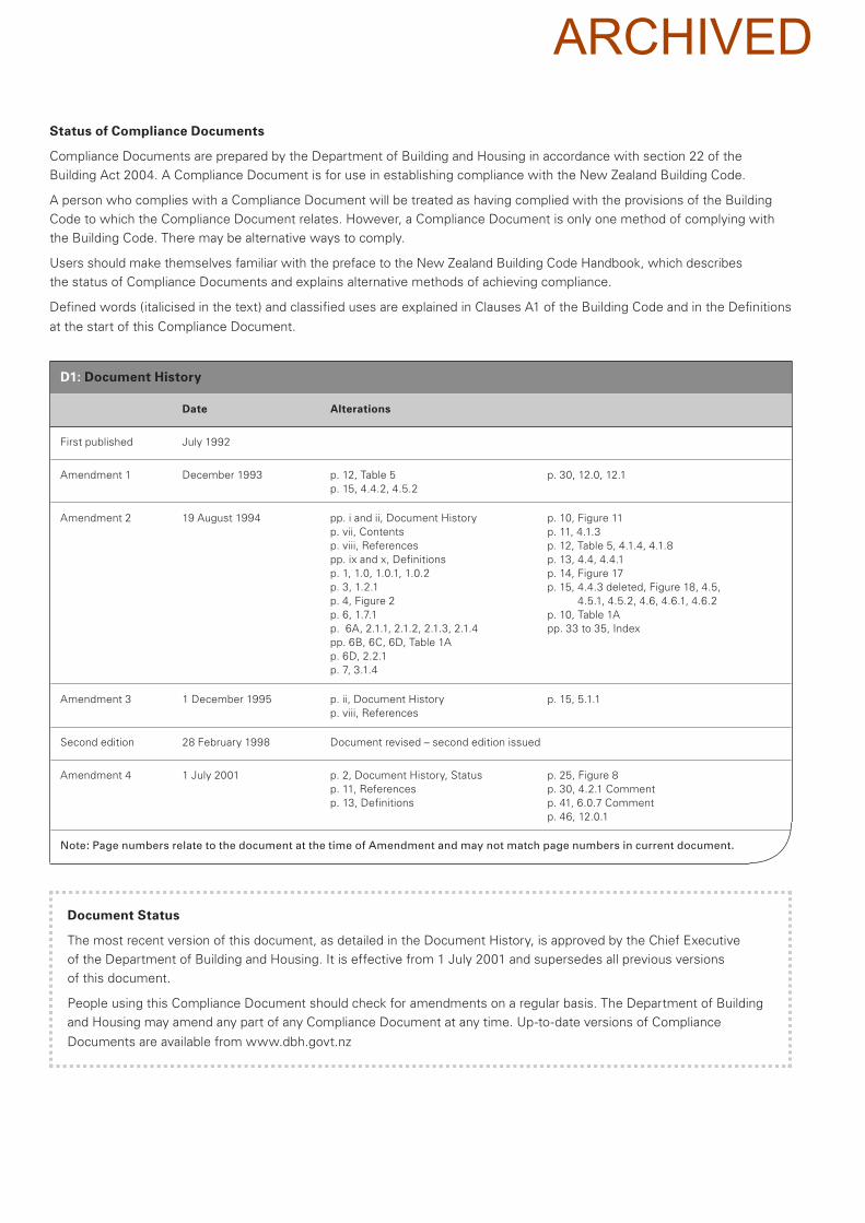
Document Status
The most recent version of this document, as detailed in the Document History, is approved by the Chief Executive
of the Department of Building and Housing. It is effective from 1 July 2001 and supersedes all previous versions
of this document.
People using this Compliance Document should check for amendments on a regular basis. The Department of Building
and Housing may amend any part of any Compliance Document at any time. Up-to-date versions of Compliance
Documents are available from www.dbh.govt.nz
D1: Document History
Date Alterations
First published July 1992
Amendment 1 December 1993 p. 12, Table 5
p. 15, 4.4.2, 4.5.2
p. 30, 12.0, 12.1
Amendment 2 19 August 1994 pp. i and ii, Document History
p. vii, Contents
p. viii, References
pp. ix and x, Definitions
p. 1, 1.0, 1.0.1, 1.0.2
p. 3, 1.2.1
p. 4, Figure 2
p. 6, 1.7.1
p. 6A, 2.1.1, 2.1.2, 2.1.3, 2.1.4
pp. 6B, 6C, 6D, Table 1A
p. 6D, 2.2.1
p. 7, 3.1.4
p. 10, Figure 11
p. 11, 4.1.3
p. 12, Table 5, 4.1.4, 4.1.8
p. 13, 4.4, 4.4.1
p. 14, Figure 17
p. 15, 4.4.3 deleted, Figure 18, 4.5,
4.5.1, 4.5.2, 4.6, 4.6.1, 4.6.2
p. 10, Table 1A
pp. 33 to 35, Index
Amendment 3 1 December 1995 p. ii, Document History
p. viii, References
p. 15, 5.1.1
Second edition 28 February 1998 Document revised – second edition issued
Amendment 4 1 July 2001 p. 2, Document History, Status
p. 11, References
p. 13, Definitions
p. 25, Figure 8
p. 30, 4.2.1 Comment
p. 41, 6.0.7 Comment
p. 46, 12.0.1
Note: Page numbers relate to the document at the time of Amendment and may not match page numbers in current document.
Status of Compliance Documents
Compliance Documents are prepared by the Department of Building and Housing in accordance with section 22 of the
Building Act 2004. A Compliance Document is for use in establishing compliance with the New Zealand Building Code.
A person who complies with a Compliance Document will be treated as having complied with the provisions of the Building
Code to which the Compliance Document relates. However, a Compliance Document is only one method of complying with
the Building Code. There may be alternative ways to comply.
Users should make themselves familiar with the preface to the New Zealand Building Code Handbook, which describes
the status of Compliance Documents and explains alternative methods of achieving compliance.
Defined words (italicised in the text) and classified uses are explained in Clauses A1 of the Building Code and in the Definitions
at the start of this Compliance Document.
ARCHIVED
3
A C C E S S R O U T E S
D E P A R T M E N T O F B U I L D I N G A N D H O U S I N G 2 8 F e b r u a r y 1 9 9 8
Clause D1
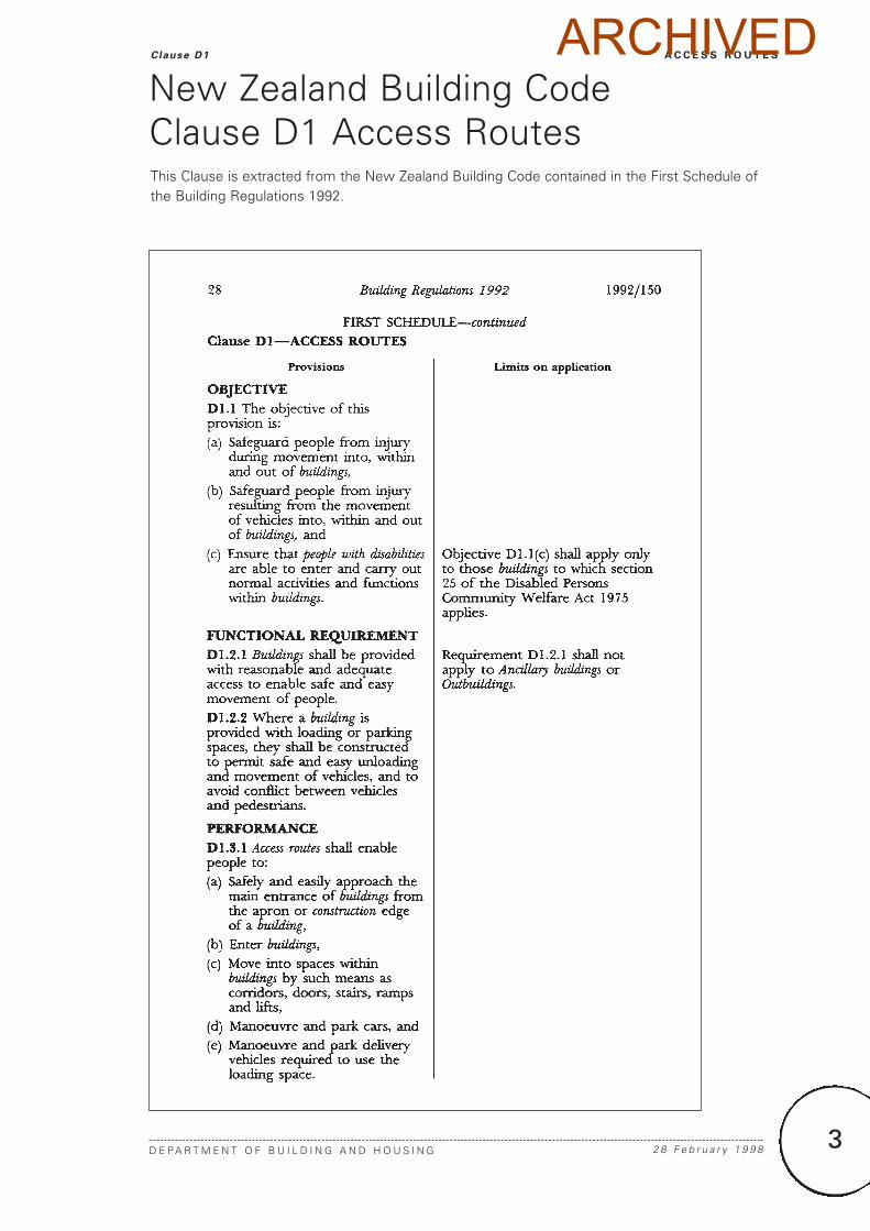
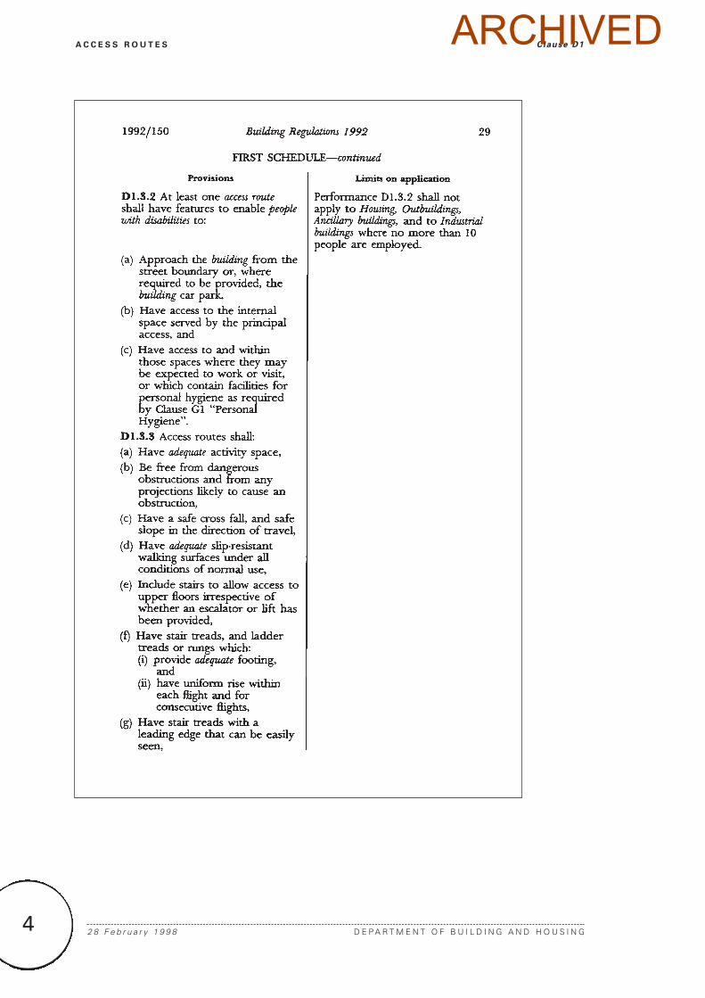
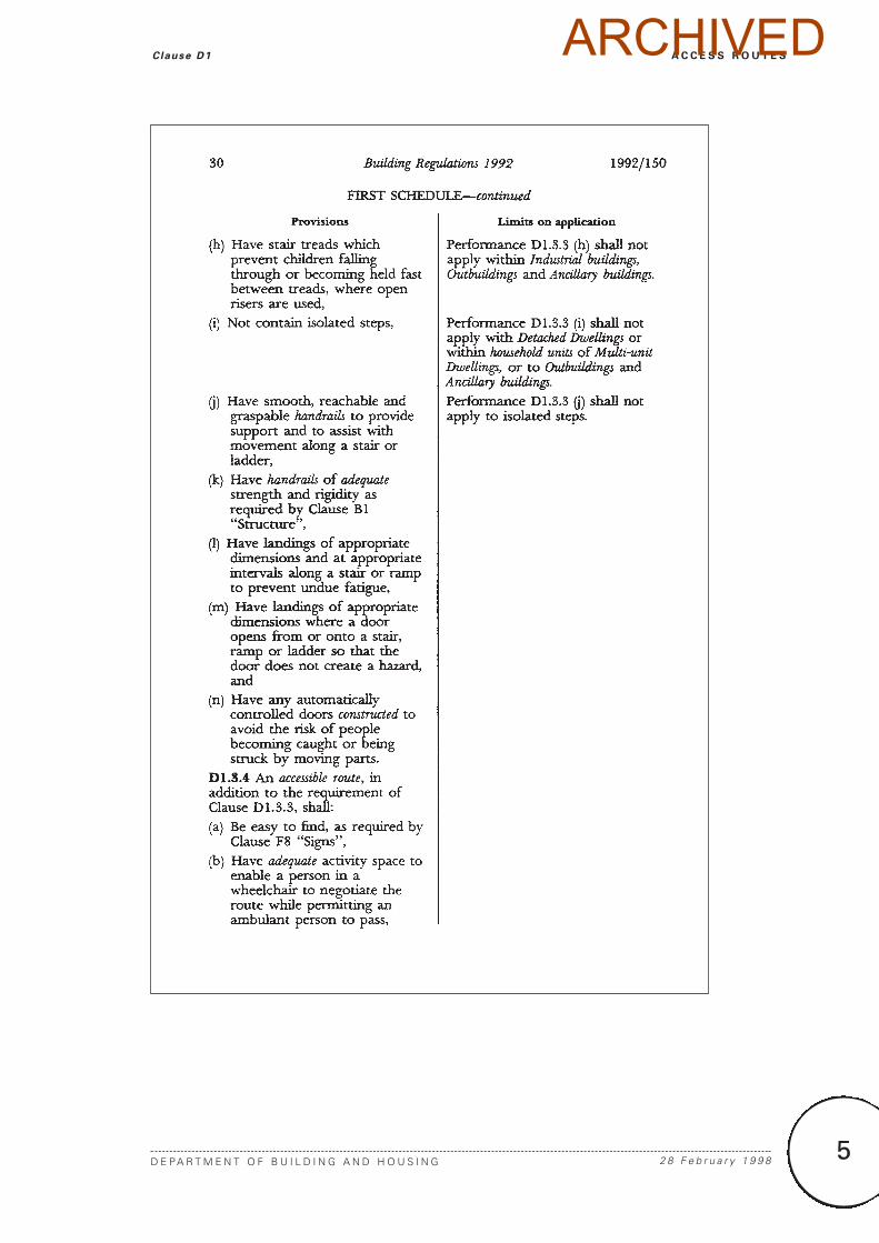
New Zealand Building Code Clause D1 Access RoutesThis Clause is extracted from the New Zealand Building Code contained in the First Schedule ofthe Building Regulations 1992.
ARCHIVED
4 2 8 F e b r u a r y 1 9 9 8 D E P A R T M E N T O F B U I L D I N G A N D H O U S I N G
A C C E S S R O U T E S Clause D1ARCHIVED
5
A C C E S S R O U T E S
D E P A R T M E N T O F B U I L D I N G A N D H O U S I N G 2 8 F e b r u a r y 1 9 9 8
Clause D1 ARCHIVED
6 2 8 F e b r u a r y 1 9 9 8 D E P A R T M E N T O F B U I L D I N G A N D H O U S I N G
A C C E S S R O U T E S Clause D1ARCHIVED
7
A C C E S S R O U T E S
D E P A R T M E N T O F B U I L D I N G A N D H O U S I N G 2 8 F e b r u a r y 1 9 9 8
Clause D1 ARCHIVED
9
A C C E S S R O U T E S
D E P A R T M E N T O F B U I L D I N G A N D H O U S I N G 2 8 F e b r u a r y 1 9 9 8
Contents D1/VM1 & AS1
Page
References 11
Definitions 13
Verification Method D1/VM1 15
1.0 Slip Resistance 15
Acceptable Solution D1/AS1 17
1.0 General Criteria 17
1.1 Location 17
1.2 Slope 17
1.3 Changes in level 17
1.4 Height clearances 18
1.5 Obstructions 18
1.6 Structural stability 20
1.7 Barriers 21
1.8 Lighting 21
2.0 Level Access Routes 21
2.1 Slip resistance 21
2.2 Width 25
2.3 Protection from falling 25
3.0 Ramps 25
3.1 Slope 25
3.2 Width 26
3.3 Landings 26
3.4 Kerb ramps 27
4.0 Stairways 27
4.1 Pitch, risers and treads 27
4.2 Width 30
4.3 Landings 31
4.4 Curved and spiral stairways 33
4.5 Stair winders 33
4.6 Visibility of stair treads 33
5.0 Fixed Ladders 34
5.1 General 34
5.2 Step-type ladders 37
5.3 Rung-type ladders 38
5.4 Individual rung-type ladders 39
6.0 Handrails 39
Page
7.0 Doors and Openings 43
8.0 Places of Assembly 43
8.1 Spaces for wheelchairs 43
8.2 Access to performance areas 43
9.0 Accessible Accommodation 43
Units of Communal Residential
Buildings
9.1 Number of units to be provided 43
9.2 Facilities to be provided 45
10.0 Movement of Vehicles 46
10.1 Car parking areas 46
10.2 Modifications to AS 2890 46
11.0 Alternative Acceptable Solutions 46
12.0 Lifts 46
Index 47
ContentsARCHIVED
A C C E S S R O U T E S
D E P A R T M E N T O F B U I L D I N G A N D H O U S I N G 1 J u l y 2 0 0 1
References D1/VM1 & AS1
11
For the purposes of New Zealand Building Code compliance, acceptable reference documentsinclude only the quoted edition and specific amendments as listed below.
Where quoted
Standards New Zealand
NZS/AS 1657: 1992 Fixed platforms, walkways, stairways and AS1 11.0.3ladders – Design, construction and installation(known as the SAA Code for fixed platforms,walkways, stairways, and ladders)
NZS 3114: 1987 Specification for concrete surface finishes AS1 Table 2Amend: 1
NZS 3116: 1991 Interlocking concrete block paving AS1 Table 2
NZS 4121: 2001 Design for access and mobility – Buildings and AS1 11.0.1,associated facilities 12.0.2
Standards Australia
AS 2890:- Off street parkingPart 1: 1993 Car parking facilities AS1 10.1, 10.2Part 2: 1989 Commercial vehicle facilities AS1 11.0.2
AS/NZS 3661:- Slip resistance of pedestrian surfacesPart 1: 1993 Requirements VM1 1.0.2,
AS1 2.1.1, 3.1.4, Table 2
Part 2: 1994 Guide to the reduction of slip hazards AS1 2.1.3
British Standards Institution
BS 585:- Wood stairs.Part 1: 1989 Specification for stairs with closed risers for AS1 4.5.3
domestic use, including straight and winder flights and quarter or half landings
BS 5395:- Stairs, ladders and walkwaysPart 2: 1984 Code of practice for the design of helical and AS1 4.4.1
spiral stairs
ReferencesAmend 4Jul 2001
Amend 4Jul 2001
ARCHIVED
13
A C C E S S R O U T E S
D E P A R T M E N T O F B U I L D I N G A N D H O U S I N G 1 J u l y 2 0 0 1
Definit ions D1/VM1 & AS1
Access route A continuous route that permitspeople and goods to move between theapron or construction edge of the buildingto spaces within a building, and betweenspaces within a building.
Accessible Having features to permit use bypeople with disabilities.
Accessible route An access route usable bypeople with disabilities. It shall be acontinuous route that can be negotiatedunaided by a wheelchair user. The routeshall extend from street boundary or carparking area to those spaces within thebuilding required to be accessible to enablepeople with disabilities to carry out normalactivities and processes within the building.
Accessible stairway A stairway havingfeatures for use by people with disabilities.Buildings required to be accessible shallhave at least one accessible stairwayleading off an accessible route whether ornot a lift is provided.
Adequate Adequate to achieve the objectivesof the building code.
Building has the meaning ascribed to it by theBuilding Act 1991.
Common ramp A ramp which is used, orintended to be used by the public whetheras of right or not, and is not a service rampor accessible ramp.
Common stairway A stairway which is used,or intended to be used, by the publicwhether as of right or not, and is not aprivate stairway, service stairway oraccessible stairway.
Handrail A rail to provide support to, or assistwith the movement of a person.
Household unit means any building or groupof buildings, or part of any building or groupof buildings, used or intended to be usedsolely or principally for residential purposesand occupied or intended to be occupiedexclusively as the home or residence of notmore than one household; but does notinclude a hostel or boardinghouse or otherspecialised accommodation.
Kerb ramp means a short ramp either cuttingthrough a kerb or built up to the kerb.
Main private stairway A private stairwayintended to provide access to and betweenfrequently used spaces such as living areas,kitchens and garages, and includes allexterior private stairways.
Minor private stairway A private stairway not on a main thoroughfare, and intended toprovide infrequent access to a single roomwhich is not a living area or kitchen.
Nosing The rounded projecting edge of a stair tread.
People with disabilities means any personwho suffers from physical or mentaldisability to such a degree that he or she isseriously limited in the extent to which heor she can engage in the activities, pursuits,and the processes of everyday life.
Pitch line The line joining the leading edge ornosings (if any) of successive stair treadswithin a single flight of a stairway.
Private stairway A stairway used, or intended to be used, by the occupants of asingle household unit.
Secondary private stairway A privatestairway other than a main or minor privatestairway, intended to provide access toanother floor containing only bedrooms,bathroom or similar accommodation.
DefinitionsThis is an abbreviated list of definitions for words or terms particularly relevant to this ApprovedDocument. The definitions for any other italicised words may be found in the New ZealandBuilding Code Handbook.
Amend 4Jul 2001
ARCHIVED
14
Service ramp means a ramp that is used, orintended to be used, infrequently by servicepersonnel to gain access to spaces for thepurposes of maintenance and themovement of goods.
Service stairway means a stairway that is used,or intended to be used, infrequently by servicepersonnel to gain access to spaces for thepurposes of maintenance and the movementof goods.
Stairway A series of steps or stairs with orwithout landings, including all necessaryhandrails and giving access between twodifferent levels.
Threshold A sill to an external door, or thefloor under an internal door.
2 8 F e b r u a r y 1 9 9 8 D E P A R T M E N T O F B U I L D I N G A N D H O U S I N G
A C C E S S R O U T E S Definit ions D1/VM1 & AS1ARCHIVED
15
A C C E S S R O U T E S
D E P A R T M E N T O F B U I L D I N G A N D H O U S I N G 2 8 F e b r u a r y 1 9 9 8
Veri f icat ion Method D1/VM1
1.0 Slip Resistance
1.0.1 Compliance with the slip-resistantperformance of NZBC D1.3.3 (d) may beverified by confirming that the walking surface under the expected conditions of usehas a coefficient of friction (µ) of no less than:
µ = 0.4 + 0.0125 S
where S is the slope of the walking surfaceexpressed as a percentage.
1.0.2 Measurement of the coefficient of friction shall be in accordance with AS/NZS 3661.1.
Verification Method D1/VM1ARCHIVED
17
A C C E S S R O U T E S
D E P A R T M E N T O F B U I L D I N G A N D H O U S I N G 2 8 F e b r u a r y 1 9 9 8
Acceptable Solut ion D1/AS1
1.0 General Criteria
1.1 Location
1.1.1 Accessible routes shall be provided togive direct access to the principal entrance tothe building where practical. If it is notpractical, the alternative most direct practicalroute to the space served by the principalentrance shall be used. The route shall havesigns complying with NZBC F8.
1.1.2 Where a site has separate buildings aspart of a single complex, accessible routesshall not deviate substantially from theconvenient or direct route commonly used.
1.1.3 Where accessible units of Communityservice buildings are provided, an accessibleroute shall connect all accessible units toreception areas, offices, shops, dining rooms,kitchens, laundries, ablution blocks, recreationrooms and any other communal facilities.
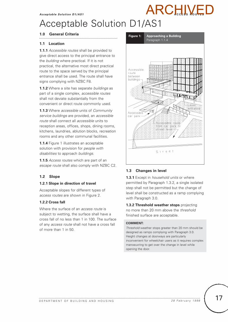
1.1.4 Figure 1 illustrates an acceptablesolution with provision for people withdisabilities to approach buildings.
1.1.5 Access routes which are part of anescape route shall also comply with NZBC C2.
1.2 Slope
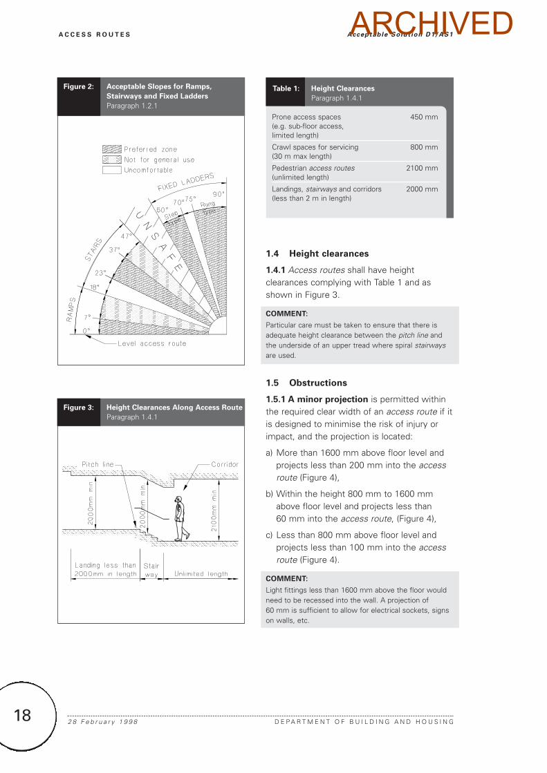
1.2.1 Slope in direction of travel
Acceptable slopes for different types ofaccess routes are shown in Figure 2.
1.2.2 Cross fall
Where the surface of an access route issubject to wetting, the surface shall have across fall of no less than 1 in 100. The surfaceof any access route shall not have a cross fallof more than 1 in 50.
1.3 Changes in level
1.3.1 Except in household units or wherepermitted by Paragraph 1.3.2, a single isolatedstep shall not be permitted but the change oflevel shall be constructed as a ramp complyingwith Paragraph 3.0.
1.3.2 Threshold weather stops projecting no more than 20 mm above the thresholdfinished surface are acceptable.
COMMENT:
Threshold weather stops greater than 20 mm should bedesigned as ramps complying with Paragraph 3.0.Height changes at doorways are particularlyinconvenient for wheelchair users as it requires complexmanoeuvring to get over the change in level whileopening the door.
Acceptable Solution D1/AS1Figure 1: Approaching a Building
Paragraph 1.1.4
ARCHIVED
18 2 8 F e b r u a r y 1 9 9 8 D E P A R T M E N T O F B U I L D I N G A N D H O U S I N G
A C C E S S R O U T E S Acceptable Solut ion D1/AS1
1.4 Height clearances
1.4.1 Access routes shall have heightclearances complying with Table 1 and asshown in Figure 3.
COMMENT:
Particular care must be taken to ensure that there isadequate height clearance between the pitch line andthe underside of an upper tread where spiral stairwaysare used.
1.5 Obstructions
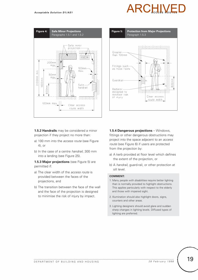
1.5.1 A minor projection is permitted withinthe required clear width of an access route if itis designed to minimise the risk of injury orimpact, and the projection is located:
a) More than 1600 mm above floor level andprojects less than 200 mm into the accessroute (Figure 4),
b) Within the height 800 mm to 1600 mmabove floor level and projects less than 60 mm into the access route, (Figure 4),
c) Less than 800 mm above floor level andprojects less than 100 mm into the accessroute (Figure 4).
COMMENT:
Light fittings less than 1600 mm above the floor wouldneed to be recessed into the wall. A projection of 60 mm is sufficient to allow for electrical sockets, signson walls, etc.
Prone access spaces 450 mm(e.g. sub-floor access, limited length)
Crawl spaces for servicing 800 mm(30 m max length)
Pedestrian access routes 2100 mm(unlimited length)
Landings, stairways and corridors 2000 mm(less than 2 m in length)
Table 1: Height Clearances
Paragraph 1.4.1
Figure 3: Height Clearances Along Access Route
Paragraph 1.4.1
Figure 2: Acceptable Slopes for Ramps,
Stairways and Fixed Ladders
Paragraph 1.2.1
ARCHIVED
19
1.5.2 Handrails may be considered a minorprojection if they project no more than:
a) 100 mm into the access route (see Figure4), or
b) In the case of a centre handrail, 300 mminto a landing (see Figure 25).
1.5.3 Major projections (see Figure 5) arepermitted if:
a) The clear width of the access route isprovided between the faces of theprojections, and
b) The transition between the face of the walland the face of the projection is designedto minimise the risk of injury by impact.
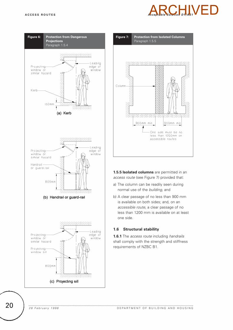
1.5.4 Dangerous projections – Windows,fittings or other dangerous obstructions mayproject into the space adjacent to an accessroute (see Figure 6) if users are protectedfrom the projection by:
a) A kerb provided at floor level which definesthe extent of the projection, or
b) A handrail, guard-rail, or other protection atsill level.
COMMENT:
1. Many people with disabilities require better lightingthan is normally provided to highlight obstructions.This applies particularly with respect to the elderlyand those with impaired sight.
2. Illumination should also highlight doors, signs,counters and other areas.
3. Lighting designers should avoid glare and suddensharp changes in lighting levels. Diffused types oflighting are preferred.
A C C E S S R O U T E S
D E P A R T M E N T O F B U I L D I N G A N D H O U S I N G 2 8 F e b r u a r y 1 9 9 8
Acceptable Solut ion D1/AS1
Figure 4: Safe Minor Projections
Paragraphs 1.5.1 and 1.5.2Figure 5: Protection from Major Projections
Paragraph 1.5.3
ARCHIVED
20
1.5.5 Isolated columns are permitted in anaccess route (see Figure 7) provided that:
a) The column can be readily seen duringnormal use of the building, and
b) A clear passage of no less than 900 mm is available on both sides; and, on anaccessible route, a clear passage of no less than 1200 mm is available on at leastone side.
1.6 Structural stability
1.6.1 The access route including handrailsshall comply with the strength and stiffnessrequirements of NZBC B1.
2 8 F e b r u a r y 1 9 9 8 D E P A R T M E N T O F B U I L D I N G A N D H O U S I N G
A C C E S S R O U T E S Acceptable Solut ion D1/AS1
Figure 6: Protection from Dangerous
Projections
Paragraph 1.5.4
Figure 7: Protection from Isolated Columns
Paragraph 1.5.5
ARCHIVED
21
1.7 Barriers
1.7.1 Barriers to prevent falling from theaccess route shall comply with NZBC F4.
COMMENT:
Barriers and handrails, having different functions, areconsidered separately in the building code. A barrier (orbalustrade on a stair) is required to prevent peoplefalling where there is a sudden change in level. Ahandrail is a graspable rail designed to guide and supportpeople using a stairway or ramp. A handrail may beattached to or form the top of a barrier where the heightis appropriate.
1.8 Lighting
1.8.1 Artificial lighting complying with NZBCG8 shall be provided along the access route.
2.0 Level Access Routes
2.1 Slip resistance
2.1.1 Level access routes to which the publichas access, including level accessible routes,shall have a mean coefficient of friction µ, ofnot less than 0.4 when tested in accordancewith AS/NZS 3661.1 (see D1/VM1).Requirements for ramps and stairways aregiven in Paragraphs 3.1.4 and 4.1.4.
COMMENT:
1. Access routes to which the public have accessinclude walking surfaces such as decks, patios andsteps on the approach to the main entrance toHousing, and common areas of CommunalResidential and Multi-unit dwelling accommodation.
2. For other access routes a coefficient of friction of lessthan 0.4 may be acceptable, but account should betaken of the effectiveness of the surface when wornor wet.
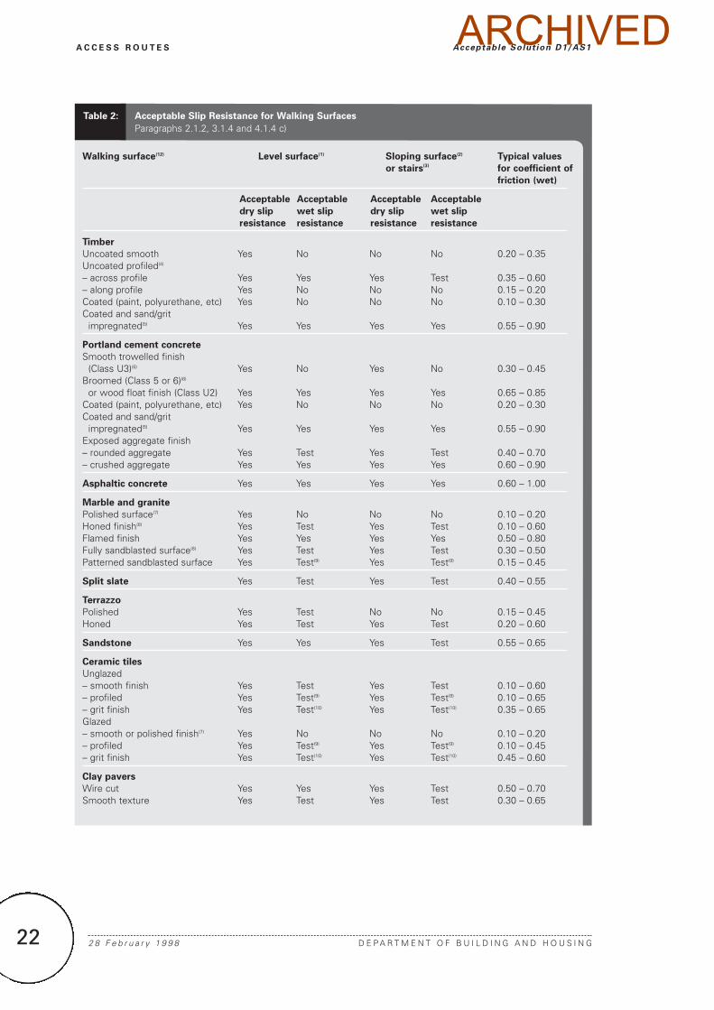
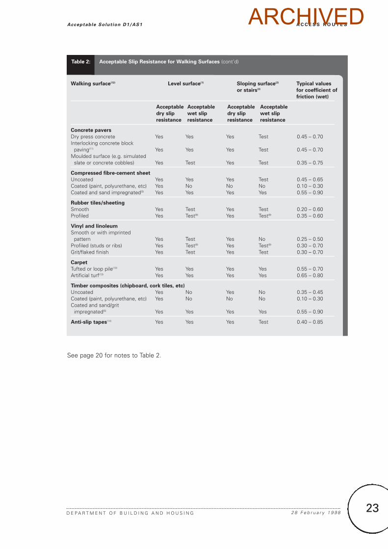
2.1.2 For a level access route which isintended to remain dry under normal usage,any of the commonly used walking surfaceslisted in Table 2 will provide adequate slipresistance (µ > 0.4).
COMMENT:
1. A cleaning regime should be established by thebuilding owner to effectively maintain the slipresistance of the walking surface.
2. Whenever a normally dry surface is wet, such as fromcleaning or isolated spillage, at a time when the publichave access, adequate signage should be used toidentify the hazard. (Many walking surfaces which areslip resistant in the dry become very slippery whenwet and can be the cause of slip injuries aspedestrians are unaware of the rapid change of slipresistance and have not altered their gait accordingly.)
3. Slipping may still occur on slip resistant walkingsurfaces as other factors such as the use ofunsuitable footwear or unusual gaits also influenceslip resistance.
2.1.3 The walking surface for a level accessroute which may become wet during normalusage (for example, outdoor access routes orentranceways where water can be trackedindoors when it is raining) shall be selectedfrom the list of acceptable wet slip resistantsurfaces given in Table 2.
COMMENT:
1. Testing as prescribed by D1/VM1 may be used tosupplement Table 2.
2. The manner in which a surface wears will affect theslip resistance. This is particularly relevant to wet slipresistant surfaces if wear results in a polishing of the surface.
3. Allowing the surface texture to become clogged withdirt (through inadequate cleaning regimes) or thebuildup of polishes or waxes can similarly impair slipresistance. (This comment is applicable for both dryand wet surfaces.) Guidance on the maintenance ofslip resistance is given in AS/NZS 3661.2.
A C C E S S R O U T E S
D E P A R T M E N T O F B U I L D I N G A N D H O U S I N G 2 8 F e b r u a r y 1 9 9 8
Acceptable Solut ion D1/AS1 ARCHIVED
Walking surface(12) Level surface(1) Sloping surface(2) Typical values
or stairs(3) for coefficient of
friction (wet)
Acceptable Acceptable Acceptable Acceptable
dry slip wet slip dry slip wet slip
resistance resistance resistance resistance
Timber
Uncoated smooth Yes No No No 0.20 – 0.35Uncoated profiled(4)
– across profile Yes Yes Yes Test 0.35 – 0.60 – along profile Yes No No No 0.15 – 0.20Coated (paint, polyurethane, etc) Yes No No No 0.10 – 0.30Coated and sand/grit
impregnated(5) Yes Yes Yes Yes 0.55 – 0.90
Portland cement concrete
Smooth trowelled finish (Class U3)(6) Yes No Yes No 0.30 – 0.45
Broomed (Class 5 or 6)(6)
or wood float finish (Class U2) Yes Yes Yes Yes 0.65 – 0.85Coated (paint, polyurethane, etc) Yes No No No 0.20 – 0.30Coated and sand/grit
impregnated(5) Yes Yes Yes Yes 0.55 – 0.90Exposed aggregate finish– rounded aggregate Yes Test Yes Test 0.40 – 0.70– crushed aggregate Yes Yes Yes Yes 0.60 – 0.90
Asphaltic concrete Yes Yes Yes Yes 0.60 – 1.00
Marble and granite
Polished surface(7) Yes No No No 0.10 – 0.20Honed finish(8) Yes Test Yes Test 0.10 – 0.60Flamed finish Yes Yes Yes Yes 0.50 – 0.80Fully sandblasted surface(8) Yes Test Yes Test 0.30 – 0.50Patterned sandblasted surface Yes Test(9) Yes Test(9) 0.15 – 0.45
Split slate Yes Test Yes Test 0.40 – 0.55
Terrazzo
Polished Yes Test No No 0.15 – 0.45Honed Yes Test Yes Test 0.20 – 0.60
Sandstone Yes Yes Yes Test 0.55 – 0.65
Ceramic tiles
Unglazed– smooth finish Yes Test Yes Test 0.10 – 0.60– profiled Yes Test(9) Yes Test(9) 0.10 – 0.65– grit finish Yes Test(10) Yes Test(10) 0.35 – 0.65Glazed– smooth or polished finish(7) Yes No No No 0.10 – 0.20– profiled Yes Test(9) Yes Test(9) 0.10 – 0.45– grit finish Yes Test(10) Yes Test(10) 0.45 – 0.60
Clay pavers
Wire cut Yes Yes Yes Test 0.50 – 0.70Smooth texture Yes Test Yes Test 0.30 – 0.65
Table 2: Acceptable Slip Resistance for Walking Surfaces
Paragraphs 2.1.2, 3.1.4 and 4.1.4 c)
22 2 8 F e b r u a r y 1 9 9 8 D E P A R T M E N T O F B U I L D I N G A N D H O U S I N G
A C C E S S R O U T E S Acceptable Solut ion D1/AS1ARCHIVED
23
A C C E S S R O U T E S
D E P A R T M E N T O F B U I L D I N G A N D H O U S I N G 2 8 F e b r u a r y 1 9 9 8
Acceptable Solut ion D1/AS1
Walking surface(12) Level surface(1) Sloping surface(2) Typical values
or stairs(3) for coefficient of
friction (wet)
Acceptable Acceptable Acceptable Acceptable
dry slip wet slip dry slip wet slip
resistance resistance resistance resistance
Concrete pavers
Dry press concrete Yes Yes Yes Test 0.45 – 0.70Interlocking concrete block
paving(11) Yes Yes Yes Test 0.45 – 0.70Moulded surface (e.g. simulated
slate or concrete cobbles) Yes Test Yes Test 0.35 – 0.75
Compressed fibre-cement sheet
Uncoated Yes Yes Yes Test 0.45 – 0.65Coated (paint, polyurethane, etc) Yes No No No 0.10 – 0.30Coated and sand impregnated(5) Yes Yes Yes Yes 0.55 – 0.90
Rubber tiles/sheeting
Smooth Yes Test Yes Test 0.20 – 0.60Profiled Yes Test(9) Yes Test(9) 0.35 – 0.60
Vinyl and linoleum
Smooth or with imprinted pattern Yes Test Yes No 0.25 – 0.50
Profiled (studs or ribs) Yes Test(9) Yes Test(9) 0.30 – 0.70Grit/flaked finish Yes Test Yes Test 0.30 – 0.70
Carpet
Tufted or loop pile(13) Yes Yes Yes Yes 0.55 – 0.70Artificial turf(13) Yes Yes Yes Yes 0.65 – 0.80
Timber composites (chipboard, cork tiles, etc)
Uncoated Yes No Yes No 0.35 – 0.45Coated (paint, polyurethane, etc) Yes No No No 0.10 – 0.30Coated and sand/grit
impregnated(5) Yes Yes Yes Yes 0.55 – 0.90
Anti-slip tapes(14) Yes Yes Yes Test 0.40 – 0.85
Table 2: Acceptable Slip Resistance for Walking Surfaces (cont’d)
See page 20 for notes to Table 2.
ARCHIVED
24 2 8 F e b r u a r y 1 9 9 8 D E P A R T M E N T O F B U I L D I N G A N D H O U S I N G
A C C E S S R O U T E S Acceptable Solut ion D1/AS1
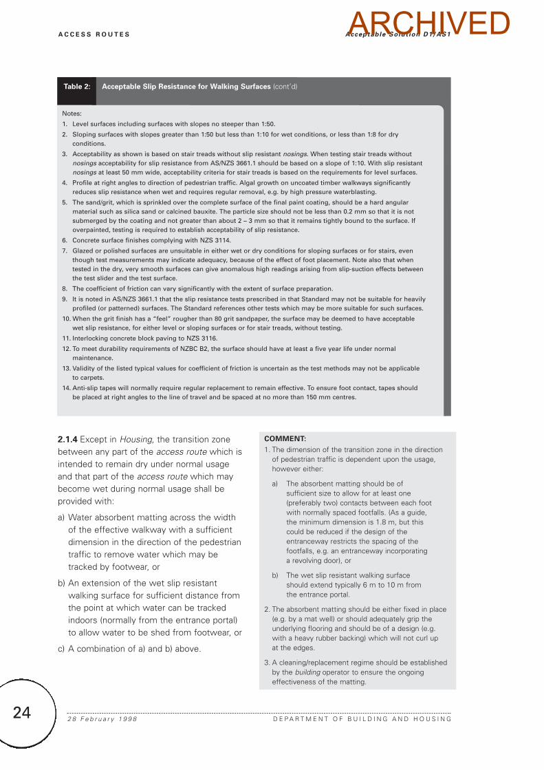
2.1.4 Except in Housing, the transition zonebetween any part of the access route which isintended to remain dry under normal usageand that part of the access route which maybecome wet during normal usage shall beprovided with:
a) Water absorbent matting across the widthof the effective walkway with a sufficientdimension in the direction of the pedestriantraffic to remove water which may betracked by footwear, or
b) An extension of the wet slip resistantwalking surface for sufficient distance fromthe point at which water can be trackedindoors (normally from the entrance portal)to allow water to be shed from footwear, or
c) A combination of a) and b) above.
COMMENT:
1. The dimension of the transition zone in the directionof pedestrian traffic is dependent upon the usage,however either:
a) The absorbent matting should be of sufficient size to allow for at least one (preferably two) contacts between each foot with normally spaced footfalls. (As a guide, the minimum dimension is 1.8 m, but this could be reduced if the design of the entranceway restricts the spacing of the footfalls, e.g. an entranceway incorporating a revolving door), or
b) The wet slip resistant walking surface should extend typically 6 m to 10 m from the entrance portal.
2. The absorbent matting should be either fixed in place(e.g. by a mat well) or should adequately grip theunderlying flooring and should be of a design (e.g.with a heavy rubber backing) which will not curl up at the edges.
3. A cleaning/replacement regime should be establishedby the building operator to ensure the ongoingeffectiveness of the matting.
Notes:
1. Level surfaces including surfaces with slopes no steeper than 1:50.
2. Sloping surfaces with slopes greater than 1:50 but less than 1:10 for wet conditions, or less than 1:8 for dryconditions.
3. Acceptability as shown is based on stair treads without slip resistant nosings. When testing stair treads withoutnosings acceptability for slip resistance from AS/NZS 3661.1 should be based on a slope of 1:10. With slip resistantnosings at least 50 mm wide, acceptability criteria for stair treads is based on the requirements for level surfaces.
4. Profile at right angles to direction of pedestrian traffic. Algal growth on uncoated timber walkways significantlyreduces slip resistance when wet and requires regular removal, e.g. by high pressure waterblasting.
5. The sand/grit, which is sprinkled over the complete surface of the final paint coating, should be a hard angularmaterial such as silica sand or calcined bauxite. The particle size should not be less than 0.2 mm so that it is notsubmerged by the coating and not greater than about 2 – 3 mm so that it remains tightly bound to the surface. Ifoverpainted, testing is required to establish acceptability of slip resistance.
6. Concrete surface finishes complying with NZS 3114.
7. Glazed or polished surfaces are unsuitable in either wet or dry conditions for sloping surfaces or for stairs, eventhough test measurements may indicate adequacy, because of the effect of foot placement. Note also that whentested in the dry, very smooth surfaces can give anomalous high readings arising from slip-suction effects betweenthe test slider and the test surface.
8. The coefficient of friction can vary significantly with the extent of surface preparation.
9. It is noted in AS/NZS 3661.1 that the slip resistance tests prescribed in that Standard may not be suitable for heavilyprofiled (or patterned) surfaces. The Standard references other tests which may be more suitable for such surfaces.
10. When the grit finish has a “feel” rougher than 80 grit sandpaper, the surface may be deemed to have acceptablewet slip resistance, for either level or sloping surfaces or for stair treads, without testing.
11. Interlocking concrete block paving to NZS 3116.
12. To meet durability requirements of NZBC B2, the surface should have at least a five year life under normalmaintenance.
13. Validity of the listed typical values for coefficient of friction is uncertain as the test methods may not be applicableto carpets.
14. Anti-slip tapes will normally require regular replacement to remain effective. To ensure foot contact, tapes shouldbe placed at right angles to the line of travel and be spaced at no more than 150 mm centres.
Table 2: Acceptable Slip Resistance for Walking Surfaces (cont’d)
ARCHIVED
25
A C C E S S R O U T E S
D E P A R T M E N T O F B U I L D I N G A N D H O U S I N G 1 J u l y 2 0 0 1
Acceptable Solut ion D1/AS1
2.2 Width
2.2.1 The clear width of an accessible routeshall be no less than 1200 mm.
COMMENT:
Handrails and other minor obstructions complying withParagraphs 1.5.1 and 1.5.2 are permitted to intrude intothis width.
2.3 Protection from falling
2.3.1 Where the surface of an accessible routeis more than 25 mm above the adjacentground, protection is to be provided by eithera 75 mm upstand (kerb) or a low barrier rail.
3.0 Ramps
3.1 Slope
3.1.1 The maximum acceptable slopes forramps are given in Table 3. The choice ofslope must take account of the type of useand risk of slipping.
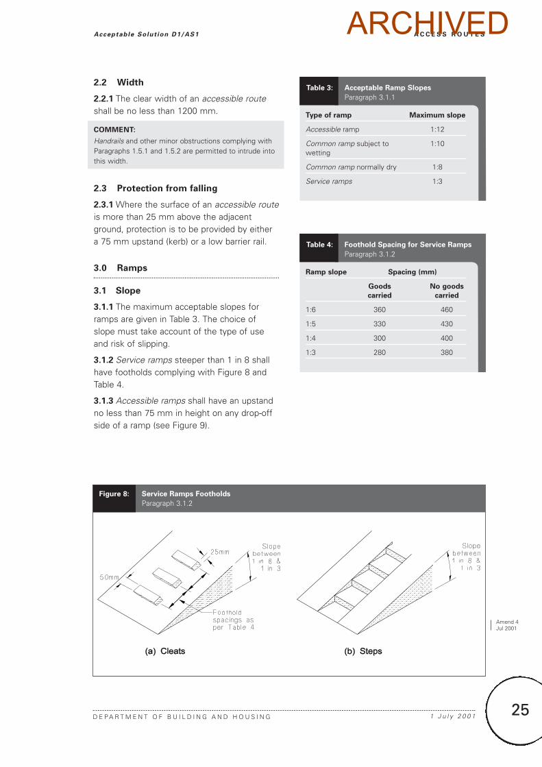
3.1.2 Service ramps steeper than 1 in 8 shallhave footholds complying with Figure 8 andTable 4.
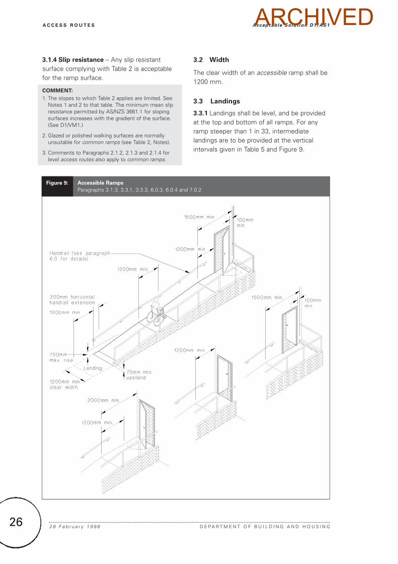
3.1.3 Accessible ramps shall have an upstandno less than 75 mm in height on any drop-offside of a ramp (see Figure 9).
Type of ramp Maximum slope
Accessible ramp 1:12
Common ramp subject to 1:10wetting
Common ramp normally dry 1:8
Service ramps 1:3
Table 3: Acceptable Ramp Slopes
Paragraph 3.1.1
Ramp slope Spacing (mm)
Goods No goods
carried carried
1:6 360 460
1:5 330 430
1:4 300 400
1:3 280 380
Table 4: Foothold Spacing for Service Ramps
Paragraph 3.1.2
Figure 8: Service Ramps Footholds
Paragraph 3.1.2
Amend 4Jul 2001
ARCHIVED
26 2 8 F e b r u a r y 1 9 9 8 D E P A R T M E N T O F B U I L D I N G A N D H O U S I N G
A C C E S S R O U T E S Acceptable Solut ion D1/AS1
3.1.4 Slip resistance – Any slip resistantsurface complying with Table 2 is acceptablefor the ramp surface.
COMMENT:
1. The slopes to which Table 2 applies are limited. SeeNotes 1 and 2 to that table. The minimum mean slipresistance permitted by AS/NZS 3661.1 for slopingsurfaces increases with the gradient of the surface.(See D1/VM1.)
2. Glazed or polished walking surfaces are normallyunsuitable for common ramps (see Table 2, Notes).
3. Comments to Paragraphs 2.1.2, 2.1.3 and 2.1.4 forlevel access routes also apply to common ramps.
3.2 Width
The clear width of an accessible ramp shall be1200 mm.
3.3 Landings
3.3.1 Landings shall be level, and be providedat the top and bottom of all ramps. For anyramp steeper than 1 in 33, intermediatelandings are to be provided at the verticalintervals given in Table 5 and Figure 9.
Figure 9: Accessible Ramps
Paragraphs 3.1.3, 3.3.1, 3.3.3, 6.0.3, 6.0.4 and 7.0.2
ARCHIVED
27
A C C E S S R O U T E S
D E P A R T M E N T O F B U I L D I N G A N D H O U S I N G 2 8 F e b r u a r y 1 9 9 8
Acceptable Solut ion D1/AS1
3.3.2 Landing width shall be no less than theminimum width of the ramp it serves.
3.3.3 Landing length shall comply with Table 5and Figure 9.
3.4 Kerb ramps
3.4.1 Kerb ramps (see Figure 10) shall have:
a) A slope of no greater than 1 in 8, and
b) Colour and texture contrast with theadjacent footpath.
COMMENT:
Kerb ramps allow the safe and easy movement ofwheeled trolleys and prams, as well as wheelchairs.
4.0 Stairways
4.1 Pitch, risers and treads
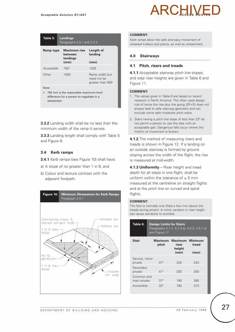
4.1.1 Acceptable stairway pitch line slopes,and step riser heights are given in Table 6 andFigure 11.
COMMENT:
1. The values given in Table 6 are based on recentresearch in North America. The often used designrule of twice the rise plus the going (2R+G) does notalways lead to safe stairway geometry and canexclude some safe moderate pitch stairs.
2. Stairs having a pitch line slope of less than 23º donot permit a person to use the stair with anacceptable gait. Dangerous falls occur where therhythm of movement is broken.
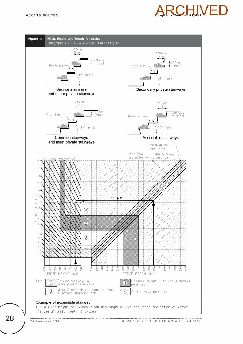
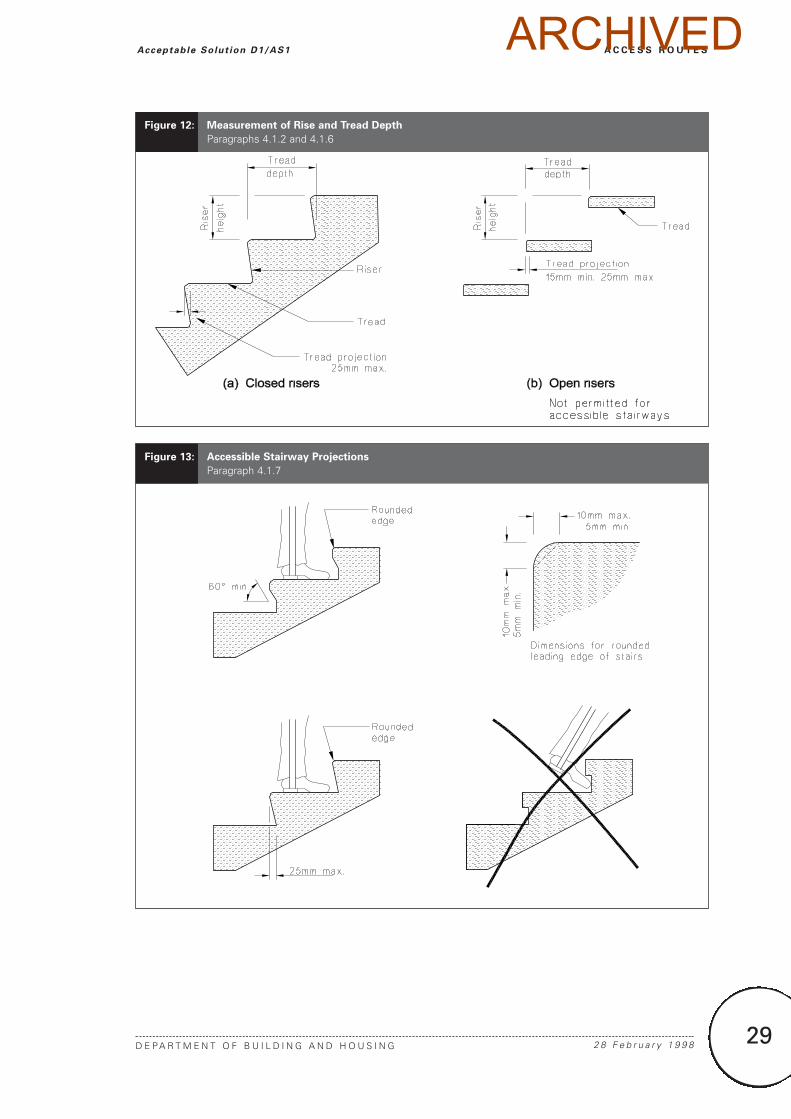
4.1.2 The method of measuring risers andtreads is shown in Figure 12. If a landing onan outside stairway is formed by groundsloping across the width of the flight, the riseis measured at mid-width.
4.1.3 Uniformity – Riser height and treaddepth for all steps in one flight, shall beuniform within the tolerance of ± 5 mmmeasured at the centreline on straight flightsand at the pitch line on curved and spiralflights.
COMMENT:
The foot is normally only lifted a few mm above thetreads during ascent. A minor variation in riser heightcan cause someone to stumble.
Stair Maximum Maximum Minimum
pitch riser tread
height
(mm) (mm)
Service, minorprivate 47° 220 220
Secondaryprivate 41° 200 250
Common andmain private 37° 190 280
Accessible 32° 180 310
Table 6: Design Limits for Stairs
Paragraphs 4.1.1, 4.1.4 a), 4.4.2, 4.5.1 a)and Figure 17
Ramp type Maximum rise Length of
between landing
landings
(mm) (mm)
Accessible 750(1) 1200
Other 1500 Ramp width but need not be greater than 900
Note:
1. 750 mm is the reasonable maximum level
difference for a person to negotiate in a
wheelchair.
Table 5: Landings
Paragraphs 3.3.1 and 3.3.3
Figure 10: Minimum Dimensions for Kerb Ramps
Paragraph 3.4.1
ARCHIVED
28 2 8 F e b r u a r y 1 9 9 8 D E P A R T M E N T O F B U I L D I N G A N D H O U S I N G
A C C E S S R O U T E S Acceptable Solut ion D1/AS1
Figure 11: Pitch, Risers and Treads for Stairs
Paragraphs 4.1.1, 4.1.4, 4.4.2, 4.5.1 a) and Figure 17
ARCHIVED
29
A C C E S S R O U T E S
D E P A R T M E N T O F B U I L D I N G A N D H O U S I N G 2 8 F e b r u a r y 1 9 9 8
Acceptable Solut ion D1/AS1
Figure 12: Measurement of Rise and Tread Depth
Paragraphs 4.1.2 and 4.1.6
Figure 13: Accessible Stairway Projections
Paragraph 4.1.7
ARCHIVED
30
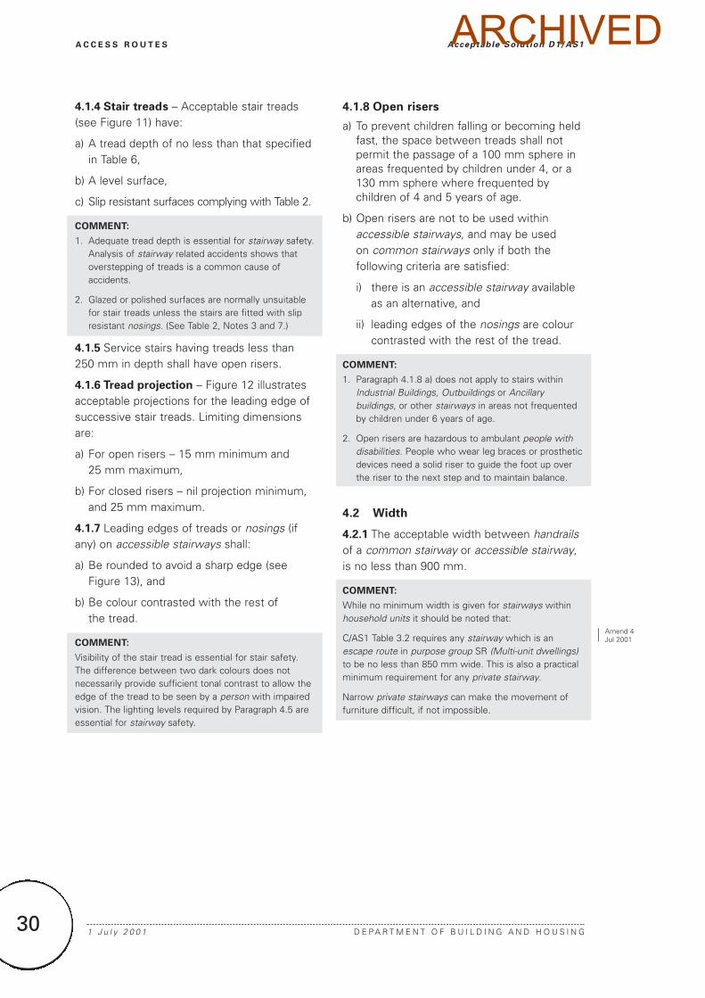
4.1.4 Stair treads – Acceptable stair treads(see Figure 11) have:
a) A tread depth of no less than that specifiedin Table 6,
b) A level surface,
c) Slip resistant surfaces complying with Table 2.
COMMENT:
1. Adequate tread depth is essential for stairway safety.Analysis of stairway related accidents shows thatoverstepping of treads is a common cause ofaccidents.
2. Glazed or polished surfaces are normally unsuitablefor stair treads unless the stairs are fitted with slipresistant nosings. (See Table 2, Notes 3 and 7.)
4.1.5 Service stairs having treads less than250 mm in depth shall have open risers.
4.1.6 Tread projection – Figure 12 illustratesacceptable projections for the leading edge ofsuccessive stair treads. Limiting dimensionsare:
a) For open risers – 15 mm minimum and 25 mm maximum,
b) For closed risers – nil projection minimum,and 25 mm maximum.
4.1.7 Leading edges of treads or nosings (ifany) on accessible stairways shall:
a) Be rounded to avoid a sharp edge (seeFigure 13), and
b) Be colour contrasted with the rest of the tread.
COMMENT:
Visibility of the stair tread is essential for stair safety.The difference between two dark colours does notnecessarily provide sufficient tonal contrast to allow theedge of the tread to be seen by a person with impairedvision. The lighting levels required by Paragraph 4.5 areessential for stairway safety.
4.1.8 Open risers
a) To prevent children falling or becoming heldfast, the space between treads shall notpermit the passage of a 100 mm sphere inareas frequented by children under 4, or a130 mm sphere where frequented bychildren of 4 and 5 years of age.
b) Open risers are not to be used withinaccessible stairways, and may be used on common stairways only if both thefollowing criteria are satisfied:
i) there is an accessible stairway available as an alternative, and
ii) leading edges of the nosings are colour contrasted with the rest of the tread.
COMMENT:
1. Paragraph 4.1.8 a) does not apply to stairs withinIndustrial Buildings, Outbuildings or Ancillarybuildings, or other stairways in areas not frequentedby children under 6 years of age.
2. Open risers are hazardous to ambulant people withdisabilities. People who wear leg braces or prostheticdevices need a solid riser to guide the foot up overthe riser to the next step and to maintain balance.
4.2 Width
4.2.1 The acceptable width between handrailsof a common stairway or accessible stairway,is no less than 900 mm.
COMMENT:
While no minimum width is given for stairways withinhousehold units it should be noted that:
C/AS1 Table 3.2 requires any stairway which is anescape route in purpose group SR (Multi-unit dwellings)to be no less than 850 mm wide. This is also a practicalminimum requirement for any private stairway.
Narrow private stairways can make the movement offurniture difficult, if not impossible.
1 J u l y 2 0 0 1 D E P A R T M E N T O F B U I L D I N G A N D H O U S I N G
A C C E S S R O U T E S Acceptable Solut ion D1/AS1
Amend 4Jul 2001
ARCHIVED
31
A C C E S S R O U T E S
D E P A R T M E N T O F B U I L D I N G A N D H O U S I N G 2 8 F e b r u a r y 1 9 9 8
Acceptable Solut ion D1/AS1
4.3 Landings
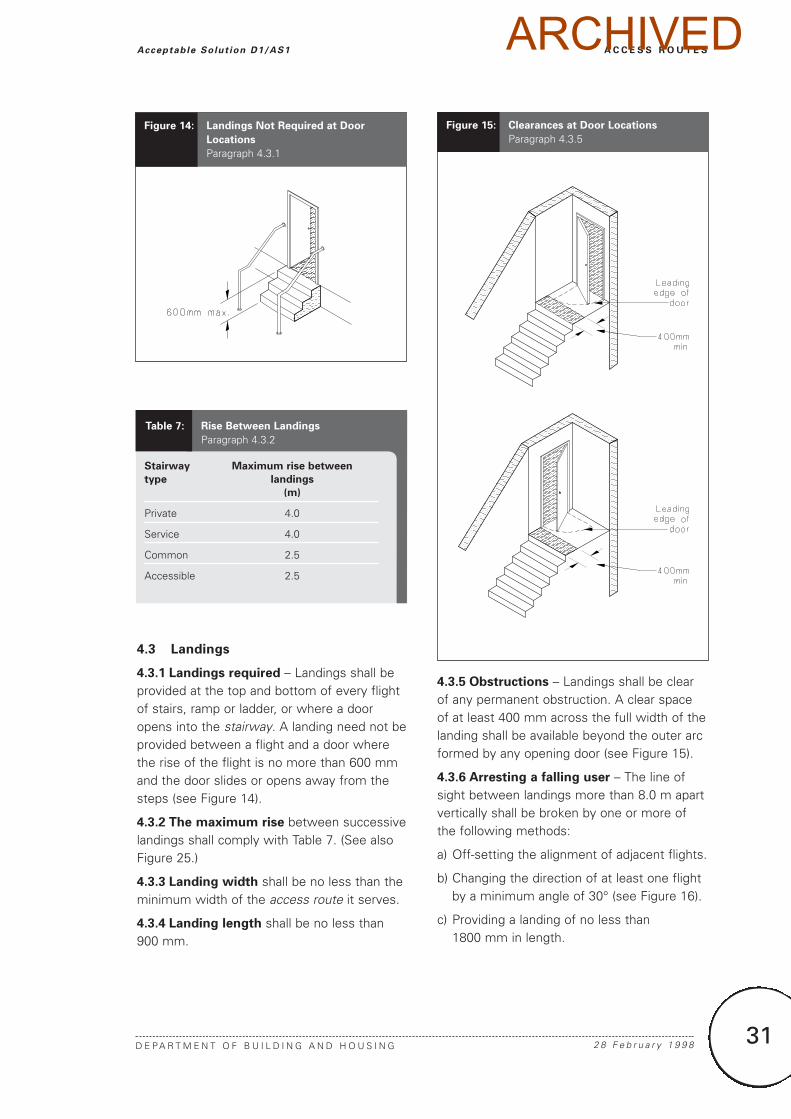
4.3.1 Landings required – Landings shall beprovided at the top and bottom of every flightof stairs, ramp or ladder, or where a dooropens into the stairway. A landing need not beprovided between a flight and a door wherethe rise of the flight is no more than 600 mmand the door slides or opens away from thesteps (see Figure 14).
4.3.2 The maximum rise between successivelandings shall comply with Table 7. (See alsoFigure 25.)
4.3.3 Landing width shall be no less than theminimum width of the access route it serves.
4.3.4 Landing length shall be no less than900 mm.
4.3.5 Obstructions – Landings shall be clearof any permanent obstruction. A clear spaceof at least 400 mm across the full width of thelanding shall be available beyond the outer arcformed by any opening door (see Figure 15).
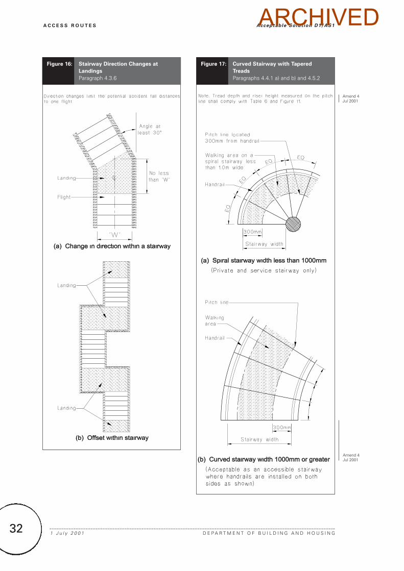
4.3.6 Arresting a falling user – The line ofsight between landings more than 8.0 m apartvertically shall be broken by one or more ofthe following methods:
a) Off-setting the alignment of adjacent flights.
b) Changing the direction of at least one flightby a minimum angle of 30° (see Figure 16).
c) Providing a landing of no less than 1800 mm in length.
Table 7: Rise Between Landings
Paragraph 4.3.2
Stairway Maximum rise between
type landings
(m)
Private 4.0
Service 4.0
Common 2.5
Accessible 2.5
Figure 14: Landings Not Required at Door
Locations
Paragraph 4.3.1
Figure 15: Clearances at Door Locations
Paragraph 4.3.5
ARCHIVED
32 1 J u l y 2 0 0 1 D E P A R T M E N T O F B U I L D I N G A N D H O U S I N G
A C C E S S R O U T E S Acceptable Solut ion D1/AS1
Figure 16: Stairway Direction Changes at
Landings
Paragraph 4.3.6
Figure 17: Curved Stairway with Tapered
Treads
Paragraphs 4.4.1 a) and b) and 4.5.2
Amend 4Jul 2001
Amend 4Jul 2001
ARCHIVED
33
4.4 Curved and spiral stairways
4.4.1 Curved and spiral stairways
with tapered treads shall have their pitch line located:
a) For a spiral stairway of width less than1000 mm – as shown in Figure 17 (a)), and
b) For a curved stairway of width 1000 mm orgreater – as shown in Figure 17 (b)).
BS 5395: Part 2 is an acceptable solution forspiral stairways having a diameter of no lessthan 1500 mm.
COMMENT:
1. The dimensions of Figure 17 are based on theassumption that people walk up and down only onthe outside of a narrow stairway, but both the insideand outside of wider stairways.
2. Spiral stairways complying with BS 5395.2 and beingless than 1500 mm in diameter (measured to theinside of handrail ), may be acceptable as anadditional means of access to spaces adequatelyserved by alternative access routes.
4.4.2 Consecutive tapered treads shall haveuniform taper angles. Pitch line slope, riserheight and tread depth along both pitch linesshall comply with Table 6 and Figure 11.
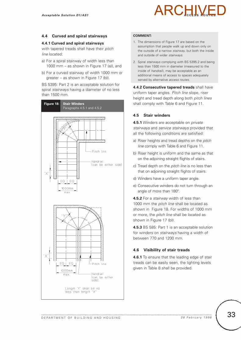
4.5 Stair winders
4.5.1 Winders are acceptable on privatestairways and service stairways provided thatall the following conditions are satisfied:
a) Riser heights and tread depths on the pitchline comply with Table 6 and Figure 11.
b) Riser height is uniform and the same as thaton the adjoining straight flights of stairs.
c) Tread depth on the pitch line is no less thanthat on adjoining straight flights of stairs.
d) Winders have a uniform taper angle.
e) Consecutive winders do not turn through anangle of more than 180º.
4.5.2 For a stairway width of less than 1000 mm the pitch line shall be located asshown in Figure 18. For widths of 1000 mmor more, the pitch line shall be located asshown in Figure 17 (b)).
4.5.3 BS 585: Part 1 is an acceptable solutionfor winders on stairways having a width ofbetween 770 and 1200 mm.
4.6 Visibility of stair treads
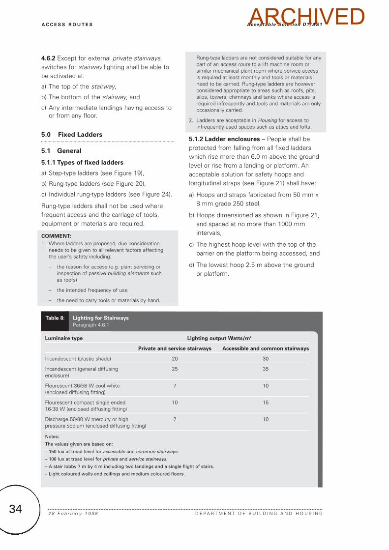
4.6.1 To ensure that the leading edge of stairtreads can be easily seen, the lighting levelsgiven in Table 8 shall be provided.
A C C E S S R O U T E S
D E P A R T M E N T O F B U I L D I N G A N D H O U S I N G 2 8 F e b r u a r y 1 9 9 8
Acceptable Solut ion D1/AS1
Figure 18: Stair Winders
Paragraphs 4.5.1 and 4.5.2
ARCHIVED
34 2 8 F e b r u a r y 1 9 9 8 D E P A R T M E N T O F B U I L D I N G A N D H O U S I N G
A C C E S S R O U T E S Acceptable Solut ion D1/AS1
4.6.2 Except for external private stairways,switches for stairway lighting shall be able tobe activated at:
a) The top of the stairway,
b) The bottom of the stairway, and
c) Any intermediate landings having access toor from any floor.
5.0 Fixed Ladders
5.1 General
5.1.1 Types of fixed ladders
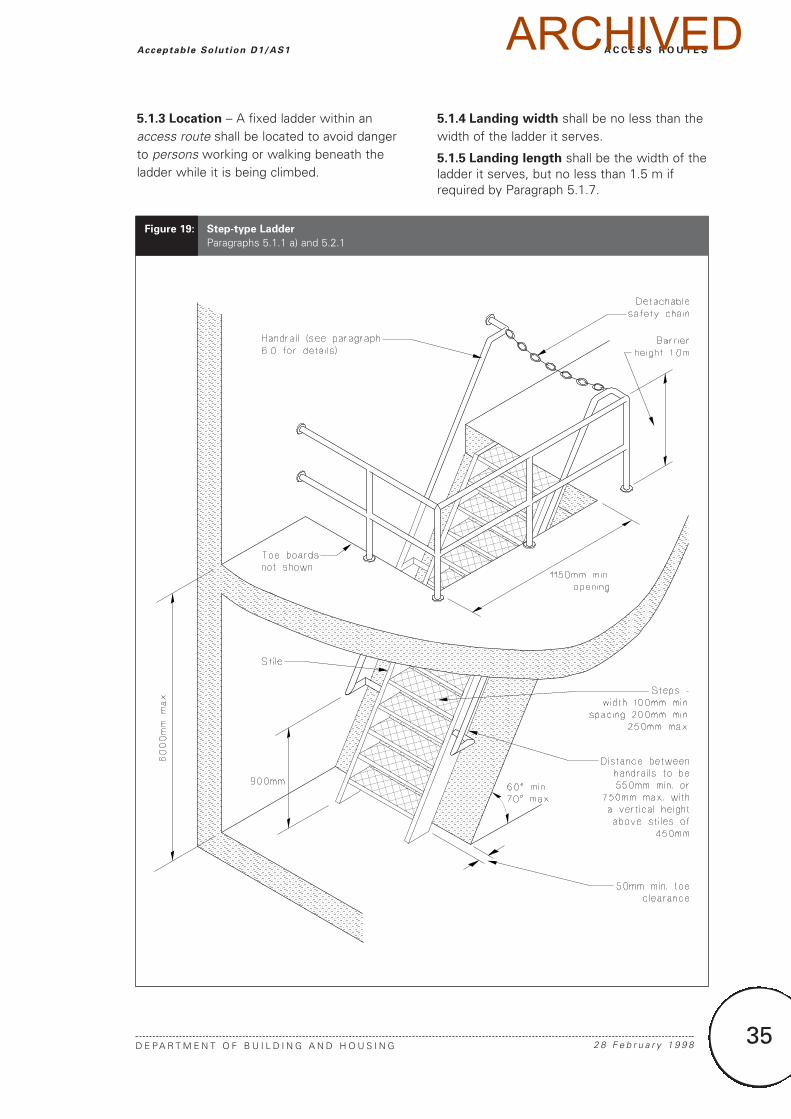
a) Step-type ladders (see Figure 19),
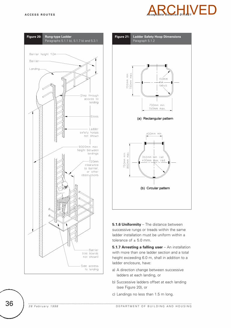
b) Rung-type ladders (see Figure 20),
c) Individual rung-type ladders (see Figure 24).
Rung-type ladders shall not be used wherefrequent access and the carriage of tools,equipment or materials are required.
COMMENT:
1. Where ladders are proposed, due considerationneeds to be given to all relevant factors affecting the user’s safety including:
– the reason for access (e.g. plant servicing or inspection of passive building elements such as roofs)
– the intended frequency of use
– the need to carry tools or materials by hand.
Rung-type ladders are not considered suitable for anypart of an access route to a lift machine room orsimilar mechanical plant room where service accessis required at least monthly and tools or materialsneed to be carried. Rung-type ladders are howeverconsidered appropriate to areas such as roofs, pits,silos, towers, chimneys and tanks where access isrequired infrequently and tools and materials are onlyoccasionally carried.
2. Ladders are acceptable in Housing for access toinfrequently used spaces such as attics and lofts.
5.1.2 Ladder enclosures – People shall beprotected from falling from all fixed ladderswhich rise more than 6.0 m above the groundlevel or rise from a landing or platform. Anacceptable solution for safety hoops andlongitudinal straps (see Figure 21) shall have:
a) Hoops and straps fabricated from 50 mm x8 mm grade 250 steel,
b) Hoops dimensioned as shown in Figure 21,and spaced at no more than 1000 mmintervals,
c) The highest hoop level with the top of thebarrier on the platform being accessed, and
d) The lowest hoop 2.5 m above the ground or platform.
Luminaire type Lighting output Watts/m2
Private and service stairways Accessible and common stairways
Incandescent (plastic shade) 20 30
Incandescent (general diffusing 25 35enclosure)
Flourescent 36/58 W cool white 7 10(enclosed diffusing fitting)
Flourescent compact single ended 10 1516-38 W (enclosed diffusing fitting)
Discharge 50/80 W mercury or high 7 10pressure sodium (enclosed diffusing fitting)
Notes:
The values given are based on:
– 150 lux at tread level for accessible and common stairways.
– 100 lux at tread level for private and service stairways.
– A stair lobby 7 m by 4 m including two landings and a single flight of stairs.
– Light coloured walls and ceilings and medium coloured floors.
Table 8: Lighting for Stairways
Paragraph 4.6.1
ARCHIVED
35
A C C E S S R O U T E S
D E P A R T M E N T O F B U I L D I N G A N D H O U S I N G 2 8 F e b r u a r y 1 9 9 8
Acceptable Solut ion D1/AS1
5.1.3 Location – A fixed ladder within anaccess route shall be located to avoid dangerto persons working or walking beneath theladder while it is being climbed.
5.1.4 Landing width shall be no less than thewidth of the ladder it serves.
5.1.5 Landing length shall be the width of theladder it serves, but no less than 1.5 m ifrequired by Paragraph 5.1.7.
Figure 19: Step-type Ladder
Paragraphs 5.1.1 a) and 5.2.1
ARCHIVED
36
5.1.6 Uniformity – The distance betweensuccessive rungs or treads within the sameladder installation must be uniform within atolerance of ± 5.0 mm.
5.1.7 Arresting a falling user – An installationwith more than one ladder section and a totalheight exceeding 6.0 m, shall in addition to aladder enclosure, have:
a) A direction change between successiveladders at each landing, or
b) Successive ladders offset at each landing(see Figure 20), or
c) Landings no less than 1.5 m long.
2 8 F e b r u a r y 1 9 9 8 D E P A R T M E N T O F B U I L D I N G A N D H O U S I N G
A C C E S S R O U T E S Acceptable Solut ion D1/AS1
Figure 20: Rung-type Ladder
Paragraphs 5.1.1 b), 5.1.7 b) and 5.3.1Figure 21: Ladder Safety Hoop Dimensions
Paragraph 5.1.2
ARCHIVED
37
A C C E S S R O U T E S
D E P A R T M E N T O F B U I L D I N G A N D H O U S I N G 2 8 F e b r u a r y 1 9 9 8
Acceptable Solut ion D1/AS1
5.2 Step-type ladders
5.2.1 Step-type ladders (see Figure 19) shall have:
a) A slope of between 60° and 70° from the horizontal,
b) Treads no less than 100 mm wide andspaced evenly at between 200 mm and 250 mm centres,
c) A width between stiles of no less than 450 mm,
d) A height between landings of no morethan 6.0 m,
e) Clearances of at least:
i) 50 mm for hand movement along the handrail,
ii) 50 mm between the treads and any solidobjects behind the ladder,
f) Horizontal openings at landings of notless than 1150 mm (see Figure 19), and
g) Handrails which:
i) are fitted on both sides of the ladder,
ii) are spaced between 550 mm and 750 mm apart,
iii) are located at a vertical distance above the stile of no more than 450 mm,
iv) commence no less than 900 mm above floor level,
v) extend above the upper landing by no less than 900 mm to connect with a barrier (if any), and
vi) are constructed to comply with Paragraphs 6.0.1 to 6.0.6.
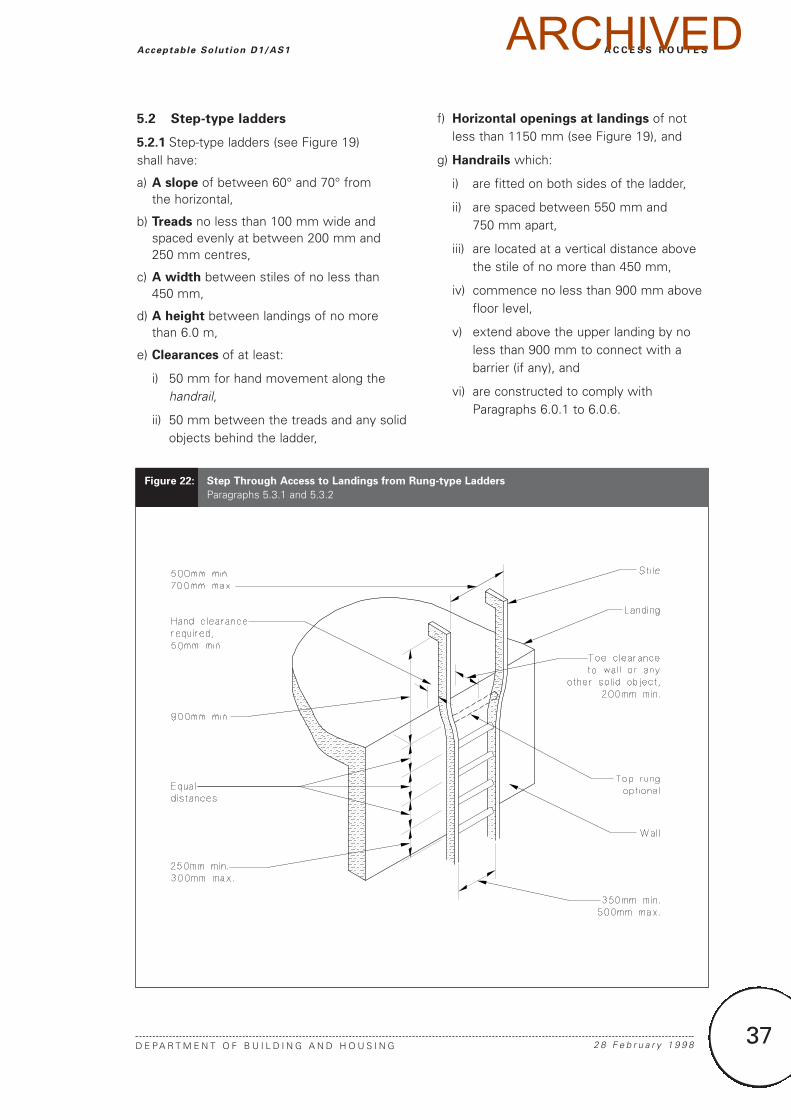
Figure 22: Step Through Access to Landings from Rung-type Ladders
Paragraphs 5.3.1 and 5.3.2
ARCHIVED
38
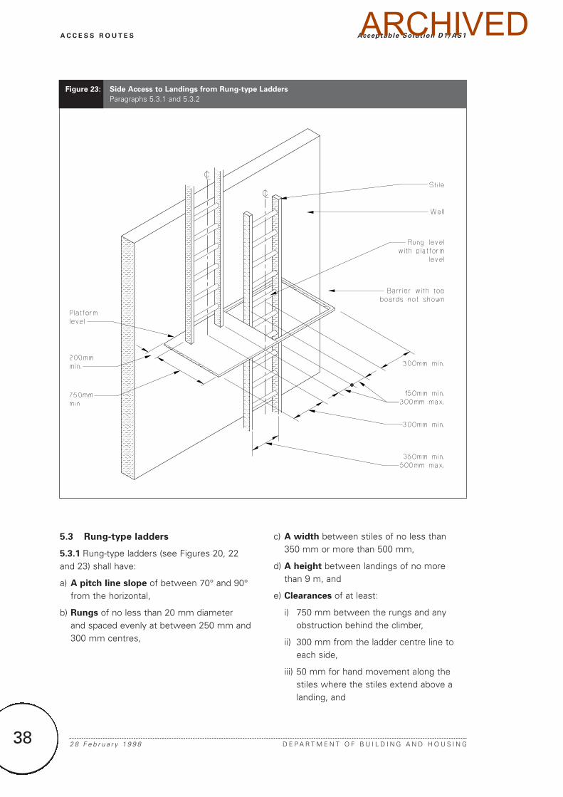
5.3 Rung-type ladders
5.3.1 Rung-type ladders (see Figures 20, 22and 23) shall have:
a) A pitch line slope of between 70° and 90°from the horizontal,
b) Rungs of no less than 20 mm diameter and spaced evenly at between 250 mm and 300 mm centres,
c) A width between stiles of no less than 350 mm or more than 500 mm,
d) A height between landings of no morethan 9 m, and
e) Clearances of at least:
i) 750 mm between the rungs and any obstruction behind the climber,
ii) 300 mm from the ladder centre line to each side,
iii) 50 mm for hand movement along the stiles where the stiles extend above a landing, and
2 8 F e b r u a r y 1 9 9 8 D E P A R T M E N T O F B U I L D I N G A N D H O U S I N G
A C C E S S R O U T E S Acceptable Solut ion D1/AS1
Figure 23: Side Access to Landings from Rung-type Ladders
Paragraphs 5.3.1 and 5.3.2
ARCHIVED
39
A C C E S S R O U T E S
D E P A R T M E N T O F B U I L D I N G A N D H O U S I N G 2 8 F e b r u a r y 1 9 9 8
Acceptable Solut ion D1/AS1
iv) 200 mm between the rungs and any solid objects behind the ladder.
5.3.2 Access to landings (see Figures 22 and 23).
a) Ladder stiles shall extend to the height ofthe barrier, but no less than 900 mm abovethe landing.
b) Toeboards shall not extend across ladderopenings.
c) For step-through access, stile spacingabove the landing shall be between 500 mm and 700 mm, and the top rung either level with, or one full rise below, the landing.
d) For side access to landings, the spacingfrom the nearest stile to the landing shallbe between 150 mm and 300 mm, and thetop rung must be level with the landing.
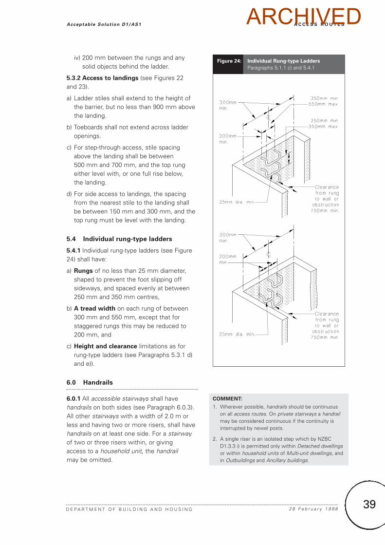
5.4 Individual rung-type ladders
5.4.1 Individual rung-type ladders (see Figure24) shall have:
a) Rungs of no less than 25 mm diameter,shaped to prevent the foot slipping offsideways, and spaced evenly at between250 mm and 350 mm centres,
b) A tread width on each rung of between300 mm and 550 mm, except that forstaggered rungs this may be reduced to200 mm, and
c) Height and clearance limitations as forrung-type ladders (see Paragraphs 5.3.1 d)and e)).
6.0 Handrails
6.0.1 All accessible stairways shall havehandrails on both sides (see Paragraph 6.0.3).All other stairways with a width of 2.0 m orless and having two or more risers, shall havehandrails on at least one side. For a stairwayof two or three risers within, or giving access to a household unit, the handrailmay be omitted.
COMMENT:
1. Wherever possible, handrails should be continuouson all access routes. On private stairways a handrailmay be considered continuous if the continuity isinterrupted by newel posts.
2. A single riser is an isolated step which by NZBCD1.3.3 i) is permitted only within Detached dwellingsor within household units of Multi-unit dwellings, andin Outbuildings and Ancillary buildings.
Figure 24: Individual Rung-type Ladders
Paragraphs 5.1.1 c) and 5.4.1
ARCHIVED
40 2 8 F e b r u a r y 1 9 9 8 D E P A R T M E N T O F B U I L D I N G A N D H O U S I N G
A C C E S S R O U T E S Acceptable Solut ion D1/AS1
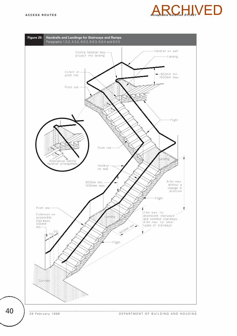
Figure 25: Handrails and Landings for Stairways and Ramps
Paragraphs 1.5.2, 4.3.2, 6.0.2, 6.0.3, 6.0.4 and 6.0.5
ARCHIVED
41
A C C E S S R O U T E S
D E P A R T M E N T O F B U I L D I N G A N D H O U S I N G 1 J u l y 2 0 0 1
Acceptable Solut ion D1/AS1
6.0.2 Any stairway which exceeds 2.0 m inwidth shall:
a) Have handrails on both sides and, where thewidth exceeds 4.0 m, shall also have anintermediate handrail provided at the centre of the stairway, or
b) If the stairway is essentially an outdoorarchitectural feature and not required to be anaccessible stairway, have at least one handrail.Examples of such stairways are those leadingto civic areas, or to decks on Housing.
COMMENT:
A central rail gives all users a rail to use for safetypurposes. On stairways in public buildings, such assports stadia, intermediate rails are also effective forcrowd control. The 2.0 m width is a comfortable widthfor three people, two of whom can grasp a rail if anyone trips.
6.0.3 Accessible stairways and accessible
ramps – Handrails shall be provided on bothsides of accessible stairways and on bothsides of accessible ramps where the rampslope is steeper than 1 in 20. The handrailsshall be continuous except where doors arelocated on landings (see Figures 9 and 25).
6.0.4 Slope of handrails – Handrails shallhave the same slope as the pitch line, beginno further than the second riser from thelower end of the stairway, and extend the fulllength of the stairway they serve. Except that,where the handrail serves an accessiblestairway or accessible ramp, a 300 mm(minimum) horizontal extension shall beprovided at each end of the handrail, asshown in Figures 9 and 25.
6.0.5 The first riser shall be located a sufficientdistance back from the corner where the twowalls meet, to accommodate the extendedhandrail, as shown in Figure 25.
6.0.6 Height of handrails – Handrails shall bepositioned between 900 mm and 1 m abovethe pitchline (see Figure 25).
6.0.7 Handrail profiles – Handrails shall havea profile which can be readily grasped by anadult hand and shall be installed in a way thatavoids the likelihood of personal injury. Anacceptable handrail shall be shaped and
located to ensure that, under normal usage, a person’s hand will not contact adjacentwalls, supporting brackets or fixings, or anyother obstruction.
COMMENT:
It is important that in the event of stumbling on astairway or ramp an adult, even with a small hand, can firmly grasp the handrail to prevent a fall. Refer to B1/AS2 for handrail structural design requirements.
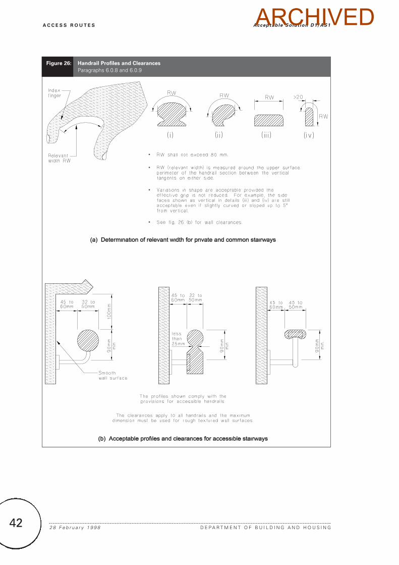
6.0.8 A graspable handrail profile shall have:
a) A flat or convex upper surface,
b) Arrised or radiused edges,
c) A minimum cross section width of 20 mm,and
d) A “relevant width” (as illustrated in Figure26 (a)) across the top surface of no greaterthan 80 mm. Figure 26 (a) and (b) indicatessome acceptable profiles but others mayalso be acceptable.
6.0.9 Acceptable handrail profiles foraccessible stairways and accessible ramps areshown in Figure 26 (b).
COMMENT:
In most circumstances a handrail is used with a lightgrip to steady the user of a stairway or ramp. Ambulantpeople with disabilities use handrails for both leverageand support, and wheelchair users often need to firmlygrip the rails to pull themselves along, particularly onramps. In those circumstances a profile offering anadequate grip is important.
Amend 4Jul 2001
ARCHIVED
42 2 8 F e b r u a r y 1 9 9 8 D E P A R T M E N T O F B U I L D I N G A N D H O U S I N G
A C C E S S R O U T E S Acceptable Solut ion D1/AS1
Figure 26: Handrail Profiles and Clearances
Paragraphs 6.0.8 and 6.0.9
ARCHIVED
43
A C C E S S R O U T E S
D E P A R T M E N T O F B U I L D I N G A N D H O U S I N G 2 8 F e b r u a r y 1 9 9 8
Acceptable Solut ion D1/AS1
7.0 Doors and Openings
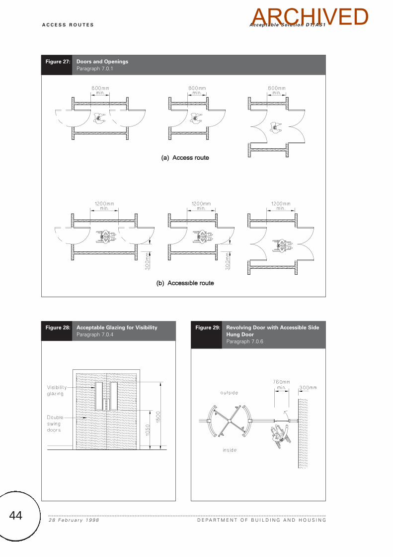
7.0.1 Lobby doors – Where doors open into alobby, the clear space between open doorsshall comply with Figure 27. Where doors,including those providing access to sanitaryfacilities, are used within an accessible routeand a person must open the door towards thewheelchair, an unobstructed wall space of notless than 300 mm shall be provided at theside of the door adjacent the handle (seeFigure 27 (b)).
COMMENT:
1. People with disabilities generally find sliding doorsmore convenient than hinged doors.
2. Sliding doors may be installed in places where ahinged door would otherwise hinder circulation ormanoeuvrability, but may only be installed inaccordance with any requirements for escape routes.
7.0.2 Other doors where located onaccessible routes shall comply with Figure 9.
7.0.3 Width – Accessible doors shall have atleast 760 mm clear opening.
7.0.4 Visibility – Doors which swing in bothdirections shall incorporate glazing to provideadequate visibility for a person using the door.Acceptable glazing is shown in Figure 28.Accessible doors shall be of a colour thatcontrasts with their surroundings.
COMMENT:
1. Glass doors set in a largely glazed wall and woodenpanel doors set in a similarly panelled wall aredifficult to locate by those with visual impairment.
2. Door handles should contrast with the door.
7.0.5 Door handles – Accessible doors shallbe openable with one hand and have a leveraction operation for handles, locks andlatches. Handles shall be between 900 mmand 1200 mm above floor level. Pull handlesor push plates are acceptable only wheredoors are not latched.
COMMENT:
1. People who use wheelchairs must have one handfree to propel the chair through the open door.
2. Door knobs with a twist or turn action do not providean adequate grip for people with hand impairments.
7.0.6 Revolving doors and turnstiles –Where revolving doors or turnstiles are usedwithin an accessible route, an alternativehinged or sliding door shall be provided (seeFigure 29).
7.0.7 Frameless glass doors shall complywith NZBC F2.
8.0 Places of Assembly
8.1 Spaces for wheelchairs
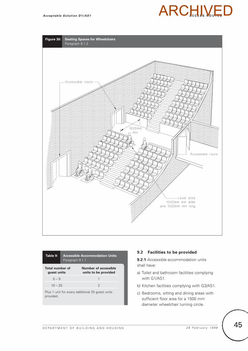
8.1.1 The number of spaces in rooms andareas used for public meetings, entertainment,and assembly, shall be provided on the scaleof 2 for up to 250 seats provided, plus 1 forevery additional 250 seats.
8.1.2 Spaces for wheelchairs shall be locatedimmediately adjacent to other seating, asshown in Figure 30.
8.2 Access to performance areas
8.2.1 An accessible route shall be provided toa podium or stage area.
9.0 Accessible Accommodation Units of
Communal Residential Buildings
9.1 Number of units to be provided
9.1.1 The number of accessibleaccommodation units to be provided in hotels, motels and other Communal Residentialbuildings providing accommodation for thepublic shall be no less than that given inTable 9.
ARCHIVED
44 2 8 F e b r u a r y 1 9 9 8 D E P A R T M E N T O F B U I L D I N G A N D H O U S I N G
A C C E S S R O U T E S Acceptable Solut ion D1/AS1
Figure 28: Acceptable Glazing for Visibility
Paragraph 7.0.4
Figure 27: Doors and Openings
Paragraph 7.0.1
Figure 29: Revolving Door with Accessible Side
Hung Door
Paragraph 7.0.6
ARCHIVED
45
A C C E S S R O U T E S
D E P A R T M E N T O F B U I L D I N G A N D H O U S I N G 2 8 F e b r u a r y 1 9 9 8
Acceptable Solut ion D1/AS1
9.2 Facilities to be provided
9.2.1 Accessible accommodation units shall have:
a) Toilet and bathroom facilities complyingwith G1/AS1.
b) Kitchen facilities complying with G3/AS1.
c) Bedrooms, sitting and dining areas withsufficient floor area for a 1500 mmdiameter wheelchair turning circle.
Total number of Number of accessible
guest units units to be provided
0 – 9 1
10 – 25 2
Plus 1 unit for every additional 25 guest unitsprovided.
Table 9: Accessible Accommodation Units
Paragraph 9.1.1
Figure 30: Seating Spaces for Wheelchairs
Paragraph 8.1.2
ARCHIVED
46 1 J u l y 2 0 0 1 D E P A R T M E N T O F B U I L D I N G A N D H O U S I N G
A C C E S S R O U T E S Acceptable Solut ion D1/AS1
10.0 Movement of Vehicles
10.1 Car parking areas
10.1.1 AS 2890: Part 1 as modified byParagraph 10.2 is an acceptable solution forcar parking areas and circulation routes.
COMMENT:
The width of an accessible car park is given in AS 2890.1 Figure 2.2 as 3.2 m, but it is noted in 2.4.1 (b) (ii) of the Standard that if there is an adjacentobstruction the width of all car parks should beincreased by 300 mm. In the case of an accessible carpark an obstruction would include a kerb or gardenwhich would prevent the movement of a wheelchair.
10.2 Modifications to AS 2890
10.2.1 AS 2890: Part 1 is modified as follows:
Clause 4.7 Lighting: After final sentence add anew sentence – “These lighting provisions may exceed the performance criteria of NZBC D1 and G8.”
Appendix C: Delete and replace with:
“Accessible car parking spaces shall be provided on the scale of:
1 for up to 10 total spaces provided
2 for up to 100 total spaces provided
plus 1 more for every additional 50 spaces
when car parks are provided in or associated with a building which is accessible.”
11.0 Alternative Acceptable Solutions
11.0.1 Accessible routes – The accessprovisions of NZS 4121 are an acceptablesolution for accessible routes, but may exceedthe requirements of NZBC D1.
11.0.2 Commercial vehicles – AS 2890: Part 2 is an acceptable solution for loadingspaces and circulation routes for commercialvehicles, but may exceed the requirements ofNZBC D1.
11.0.3 Access routes for service and
maintenance personnel – NZS/AS 1657 is an acceptable solution for fixed platforms,walkways, stairways, and ladders, but provisionsmay exceed the requirements of NZBC D1.
12.0 Lifts
12.0.1 For the purposes of determiningwhether a lift must be provided for peoplewith disabilities to access upper floors, thedesign occupancy shall be determined usingC/AS1 Paragraph 2.3.7 and Table 2.2.
COMMENT:
Alternative design occupancies being less than derivedfrom Table 2.2, must be justified with clear supportinginformation. Table 2.2 already takes account of effectivefloor area reductions for normal furnishings associatedwith a given activity, such as desks or workstations inoffices. However, in a factory situation with fixedmachinery, actual operator numbers may be acceptableas the occupant load.
12.0.2 Building size may also be used todetermine the need for a lift for people withdisabilities. NZS 4121 is an acceptable solutionbased on gross floor area.
Amend 4Jul 2001
Amend 4Jul 2001
ARCHIVED
47
A C C E S S R O U T E S
D E P A R T M E N T O F B U I L D I N G A N D H O U S I N G 2 8 F e b r u a r y 1 9 9 8
Index D1/VM1 & AS1
Access routes . . . . . . . . . . . . . . . . . . . . . .AS1 1.1.5, 1.2.2, 1.4.1, 1.5.1, 1.5.3 a), 1.5.4, 1.5.5,
1.6.1, 1.7.1, 1.8.1, 2.0, 5.1.3, 10.1.4, Figure 27
see also Level access routesservice and maintenance personnel . . . . . . . . . . . . . . . . .AS1 11.0.4
Accessible accommodation units . . . . . . . . . . . . .AS1 9.0, 9.1, 9.1.1, 9.2.1, Table 9
facilities . . . . . . . . . . . . . . . . . . . . . . . . . . . . . . . . . . . . . . . . . .AS1 9.2bedrooms . . . . . . . . . . . . . . . . . . . . . . . . . . . . . . . . . .AS1 9.2.1 c)dining areas . . . . . . . . . . . . . . . . . . . . . . . . . . . . . . . .AS1 9.2.1 c)kitchens . . . . . . . . . . . . . . . . . . . . . . . . . . . . . . . . . . .AS1 9.2.1 b)sitting areas . . . . . . . . . . . . . . . . . . . . . . . . . . . . . . . .AS1 9.2.1 c)toilets and baths . . . . . . . . . . . . . . . . . . . . . . . . . . . . .AS1 9.2.1 a)
Accessible routes . . . . . . . . . . . . . . . . . . . . . . . .AS1 1.1.1, 1.1.2, 1.1.3, 1.5.5 b), 2.1.1, 2.2.1, 2.3.1, 7.0.1,
7.0.6, 11.0.1, Figure 27access to performance areas . . . . . . . . . . . . . . . . . . . . . . . . .AS1 8.2
Accessible units . . . . . . . . . . . . . . . . . . . . . . . . . . . . . . . . . . .AS1 1.1.3
Alternative solutions . . . . . . . . . . . . . . . . . . . . . . . . . . . . . . . .AS1 11.0
Barriers . . . . . . . . . . . . . . . . . . . . . . . . . . . . . . . . . . . . . . . . . . . .AS1 1.7see also Handrails
Buildings . . . . . . . . . . . . . . . . . . . . . . . . . . . . . . .AS1 1.1.1, 1.1.2, 1.1.410.1.4, 10.4.1,
entrances . . . . . . . . . . . . . . . . . . . . . . . . . . . . . . . . . . . . . .AS1 10.1.3
Communal residential buildings . . . . . . . . . . . . . . . . . .AS1 9.0, 9.1.1
Community service buildings . . . . . . . . . . . . . . . . . . . . . . . .AS1 1.1.3
Doors . . . . . . . . . . . . . . . . . . . . . . . . . . . . . . . . . . . . .AS1 7.0, Figure 27accessible doors . . . . . . . . . . . . . . . . . . . . . . .AS1 7.0.3, 7.0.4, 7.0.5frameless glass doors . . . . . . . . . . . . . . . . . . . . . . . . . . . . .AS1 7.0.7glazing . . . . . . . . . . . . . . . . . . . . . . . . . . . . . . . . .AS1 7.0.4, Figure 28handles . . . . . . . . . . . . . . . . . . . . . . . . . . . . . . . . . . . . . . . .AS1 7.0.5lobby doors . . . . . . . . . . . . . . . . . . . . . . . . . . . . . . . . . . . . .AS1 7.0.1revolving doors . . . . . . . . . . . . . . . . . . . . . . . . . .AS1 7.0.6, Figure 29turnstiles . . . . . . . . . . . . . . . . . . . . . . . . . . . . . . . . . . . . . . .AS1 7.0.6visibility . . . . . . . . . . . . . . . . . . . . . . . . . . . . . . . . . . . . . . . .AS1 7.0.4width . . . . . . . . . . . . . . . . . . . . . . . . . . . . . . . . . . . . . . . . . .AS1 7.0.3
Escape routes . . . . . . . . . . . . . . . . . . . . . . . . . . . . . . . . . . . . .AS1 1.1.5
Index D1/VM1 & AS1All references to Verification Methods and Acceptable Solutions are preceded by VM or AS
respectively.
ARCHIVED
48 2 8 F e b r u a r y 1 9 9 8 D E P A R T M E N T O F B U I L D I N G A N D H O U S I N G
A C C E S S R O U T E S Index D1/VM1 & AS1
Handrails . . . . . . . . . . . . . . . . . . . . . . . . .AS1 1.5.2, 1.5.4 b), 1.6.1, 1.7, 5.2.1 g), 6.0, 6.0.1, 6.0.2,
Figures 6 and 19clearances . . . . . . . . . . . . . . . . . . . . . . . . . . . . . .AS1 6.0.7, Figure 26handrail profiles . . . . . . . . . . . . . . .AS1 6.0.7, 6.0.8, 6.0.9, Figure 26height . . . . . . . . . . . . . . . . . . . . . . . . . . . . . . . . .AS1 6.0.6, Figure 25horizontal extensions . . . . . . . . . . . . . . . .AS1 6.0.4, 6.0.5, Figure 25intermediate handrails . . . . . . . . . . . . . . . . . . . . . . . . . . . . .AS1 6.0.2relevant width . . . . . . . . . . . . . . . . . . . . . . . . . . .AS1 6.0.9, Figure 26slope . . . . . . . . . . . . . . . . . . . . . . . . . . . . . . . . . . . . . . . . . .AS1 6.0.4
Height clearances . . . . . . . . . . . . . . . .AS1 1.4, 1.4.1, Figure 3, Table 1
Hotels . . . . . . . . . . . . . . . . . . . . . . . . . . . . . . . . . . . . . . . . . . . .AS1 9.1.1
Kerbs . . . . . . . . . . . . . . . . . . . . . . . . . . . . . . . . . .AS1 1.5.4 a), Figure 6see also Ramps
Ladders . . . . . . . . . . . . . . . . . . . . . . . . . . . . . . . . . . . . . . .AS1 5.0, 5.1.1height . . . . . . . . . . . . . . . . . . . . . . . . . . . . . . . . . . . .AS1, 5.1.2, 5.1.7individual rung-type ladders . . . . . . . . . . .AS1 5.1.1 c), 5.4, Figure 24
clearance . . . . . . . . . . . . . . . . . . . . . . . . . . . . . . . . . .AS1 5.4.1 c)height . . . . . . . . . . . . . . . . . . . . . . . . . . . . . . . . . . . . .AS1 5.4.1 c)rungs . . . . . . . . . . . . . . . . . . . . . . . . . . . . . . . . . . . . . .AS1 5.4.1 a)tread width . . . . . . . . . . . . . . . . . . . . . . . . . . . . . . . . .AS1 5.4.1 b)width . . . . . . . . . . . . . . . . . . . . . . . . . . . . . . . . . . . . .AS1 5.4.1 b)
landings . . . . . . . . . . . . . . . . . . . . . . . . . . . . . . . . . . . . . . . .AS1 5.3.2length . . . . . . . . . . . . . . . . . . . . . . . . . . . . . . . . . .AS1 5.1.5, 5.1.7width . . . . . . . . . . . . . . . . . . . . . . . . . . . . . . . . . . . . . . . .AS1 5.1.4
location . . . . . . . . . . . . . . . . . . . . . . . . . . . . . . . . . . . . . . . .AS1 5.1.3rung spacing . . . . . . . . . . . . . . . . . . . . . . . . . . . . . . . . . . . .AS1 5.1.6rung-type ladders . . . . . . . . . . . . . . . . . . .AS1 5.1.1 b), 5.3, Figure 20
clearances . . . . . . . . . . . . . . . . . . . . . . . . . . . . . . . . .AS1 5.3.1 e)height . . . . . . . . . . . . . . . . . . . . . . . . . . . . . . . . . . . . .AS1 5.3.1 d)landings . . . . . . . . . . . . . . . . . . . . . . . . . . . . .AS1 5.3.2, Figure 23rungs . . . . . . . . . . . . . . . . . . . . . . . . . . . . . . . . . . . . .AS1 5.3.1 b)slope . . . . . . . . . . . . . . . . . . . . . . . . . . . . . . . . . . . . . .AS1 5.3.1 a)width . . . . . . . . . . . . . . . . . . . . . . . . . . . . . . . . . . . . . .AS1 5.3.1 c)
safety enclosures . . . . . . . . . . . . . . . . . . . .AS1 5.1.2, Figures 21, 22step-type ladders . . . . . . . . . . . .AS1 5.1.1 a), 5.2, 5.2.1 a), Figure 19
clearances . . . . . . . . . . . . . . . . . . . . . . . . . . . . . . . . .AS1 5.2.1 e)height . . . . . . . . . . . . . . . . . . . . . . . . . . . . . . . . . . . . .AS1 5.2.1 d)horizontal openings . . . . . . . . . . . . . . . . . . . . . . . . . . .AS1 5.2.1 f)slope . . . . . . . . . . . . . . . . . . . . . . . . . . . . . . . . . . . . . .AS1 5.2.1 a)treads . . . . . . . . . . . . . . . . . . . . . . . . . . . . . . . . . . . . .AS1 5.2.1 b)width . . . . . . . . . . . . . . . . . . . . . . . . . . . . . . . . . . . . . .AS1 5.2.1 c)
types of ladders . . . . . . . . . . . . . . . . . . . . . . . . . . . . . . . . . .AS1 5.1.1
ARCHIVED
49
A C C E S S R O U T E S
D E P A R T M E N T O F B U I L D I N G A N D H O U S I N G 2 8 F e b r u a r y 1 9 9 8
Index D1/VM1 & AS1
Level access routes . . . . . . . . . . . . . . . . . . . . . . . . . . . . . . . . . .AS1 2.0protection from falling . . . . . . . . . . . . . . . . . . . . . . . . . . . . . .AS1 2.3slip resistance . . . . . . . . . . . . . . . . . . . . . . . . . . . . . .AS1 2.1, Table 2width . . . . . . . . . . . . . . . . . . . . . . . . . . . . . . . . . . . . . . . . . . . .AS1 2.2
Lifts . . . . . . . . . . . . . . . . . . . . . . . . . . . . . . . . . . . . . . . . . . . . .AS1 12.0
Lighting . . . . . . . . . . . . . . . . . . . . . . . . . . . . . . . . . . . . . . .AS1 1.5.4, 1.8
Location . . . . . . . . . . . . . . . . . . . . . . . . . . . . . . . . . . . . . . . . . . .AS1 1.1
Motels . . . . . . . . . . . . . . . . . . . . . . . . . . . . . . . . . . . . . . . . . . .AS1 9.1.1
Obstructions . . . . . . . . . . . . . . . . . . . . . . . . . . . . . . . . . . . . . . . .AS1 1.5dangerous projections . . . . . . . . . . . . . . . . . . . . .AS1 1.5.4, Figure 6isolated columns . . . . . . . . . . . . . . . . . . . . . . . . . .AS1 1.5.5, Figure 7major projections . . . . . . . . . . . . . . . . . . . . . . . . .AS1 1.5.3, Figure 5minor projections . . . . . . . . . . . . . . . . . . . .AS1 1.5.1, 1.5.2, Figure 4
Occupancy . . . . . . . . . . . . . . . . . . . . . . . . . . . . . . . . . . . . . . . .AS1 12.0
Openings
see Doors . . . . . . . . . . . . . . . . . . . . . . . . . . . . . . . . . . . . . .AS1 7.0.1
People with disabilities . . . . . . . . . . . . . . . . . . . . . . .AS1 1.1.4, Table 9
Places of assembly . . . . . . . . . . . . . . . . . . . . . . . . . . . . . . . . . . .AS1 8.0
Principal entrance . . . . . . . . . . . . . . . . . . . . . . . . . . . . . . . . . . .AS1 1.1
Ramps . . . . . . . . . . . . . . . . . . . . . . . . . . . . . . . . . . .AS1 1.3.1, 1.3.2, 3.0accessible ramps . . . . . . . . . . . . . . . . . . . . . .AS1 3.1.3, 6.0.2, 6.0.3,
6.0.4, Figure 9slopes . . . . . . . . . . . . . . . . . . . . . . . . . . . . . . . . . . . . .AS1 Table 3width . . . . . . . . . . . . . . . . . . . . . . . . . . . . . . . . . . . . . . . . .AS1 3.2
intermediate landings . . . . . . . . . . . . . . . . . . . . . . .AS1 3.3.1, Table 5length . . . . . . . . . . . . . . . . . . . . . . . . . . . . . . . . . . . . . . .AS1 3.3.3width . . . . . . . . . . . . . . . . . . . . . . . . . . . . . . . . . . . . . . . .AS1 3.3.2
kerb ramps . . . . . . . . . . . . . . . . . . . . . . . . . . . . . . .AS1 3.4, Figure 10landings . . . . . . . . . . . . . . . . . . . . . . . . . . . . . . . . .AS1 3.3, Figure 25service ramps . . . . . . . . . . . . . . . . . . . . .AS1 3.1.2, Figure 8, Table 4slip resistance . . . . . . . . . . . . . . . . . . . . . . . . . . . .AS1 3.1.4, Table 2slopes . . . . . . . . . . . . . . . . . . . . . . . . . . . . . . . . . . . . . .AS1 3.1, 3.1.1
Signs . . . . . . . . . . . . . . . . . . . . . . . . . . . . . . . . . . . . . . . . . . . .AS1 1.1.1
Slip resistance . . . . . . . . . . .VM1 1.0, AS1 2.1, 3.1.4, 4.1.4 c), Table 2
Slopes . . . . . . . . . . . . . . . . . . . . . . . . . . . . . . . . . . . . . . . . . . . . .AS1 1.2acceptable slopes . . . . . . . . . . . . . . . . . . . . . . . . .AS1 1.2.1, Figure 2changes in level . . . . . . . . . . . . . . . . . . . . . . . . . . . . . .AS1 1.3, 1.3.1cross falls . . . . . . . . . . . . . . . . . . . . . . . . . . . . . . . . . . . . . . .AS1 1.2.2
ARCHIVED
50 2 8 F e b r u a r y 1 9 9 8 D E P A R T M E N T O F B U I L D I N G A N D H O U S I N G
A C C E S S R O U T E S Index D1/VM1 & AS1
Stairways . . . . . . . . . . . . . . . . . . . . . . . . . . . . . . . . . . . . . . . . . .AS1 4.0accessible stairways . . . . . . .AS1 4.1.7, 4.1.8 b), 4.2.1, 6.0.1, 6.0.2,
6.0.3, 6.0.4, Figure 11, Tables 6, 7, 8
common stairways . . . . . .AS1 4.1.8, 4.2.1, Figure 11, Tables 6, 7, 8curved stairways . . . . . . . . . . . . . . . . . . . . .AS1 4.1.3, 4.4, Figure 17
Stairways (continued)landings . . . . . . . . . .AS1 4.3, 4.3.1, 4.3.6 c), 4.6.2 c), Figures 14, 25
direction changes . . . . . . . . . . . . . . . . . . . . . . . . . .AS1 Figure 16length . . . . . . . . . . . . . . . . . . . . . . . . . . . . . . . .AS1 4.3.4, 4.3.6 c)maximum rise . . . . . . . . . . . . . . . . . . . . . . . . . .AS1 4.3.2, Table 7obstructions . . . . . . . . . . . . . . . . . . . . . . . . . .AS1 4.3.5, Figure 15width . . . . . . . . . . . . . . . . . . . . . . . . . . . . . . . . . . . . . . . .AS1 4.3.3
lighting . . . . . . . . . . . . . . . . . . . . . . . . . . . . . . .AS1 4.5, 4.5.2, Table 8pitch . . . . . . . . . . . . . . . . . . . . . . . . . . . . .AS1 4.1, Figure 11, Table 6pitch lines . . . . . . . . . . . . . . . . . .AS1 4.1.3, 4.4.1, 4.4.2, 4.5.1, 4.5.2private stairways . . . . . . . . . . . . . . .AS1 4.6.2, Figure 11, Tables 6, 8
main . . . . . . . . . . . . . . . . . . . . . . . . . . . . . .AS1 Figure 11, Table 6minor . . . . . . . . . . . . . . . . . . . . . . . .AS1 4.5.1, Figure 11, Table 6secondary . . . . . . . . . . . . . . . . . . . . .AS1 4.5.1, Figure 11, Table 6risers . . . . . . . . . . . . . . . . . . . . . . . . .AS1 4.1, 4.1.2, 4.1.3, 4.1.8,
4.4.2, 4.5.1, Figures 11, 12, Table 6service stairs . . . . . . . . . . . . . . . . . .AS1 4.5.1, Figure 11, Tables 6, 8slip resistance . . . . . . . . . . . . . . . . . . . . . . . . . . .AS1 4.1.4 c), Table 2spiral stairs . . . . . . . . . . . . . . . . . . . . . . . . . . . . . . . . .AS1 4.1.3, 4.4.1treads . . . . . . . . . . . . . . . . . . . . . . . . . . . .AS1 4.1, 4.1.2, 4.1.3, 4.1.4,
4.1.5, 4.1.6, 4.1.7, 4.5.1, 4.6,Figures 11, 12, 13, Table 6
tapered treads . . . . . . . . . . . . . . . . . . . . . . . . . . . .AS1 4.4, Figure 17visibility . . . . . . . . . . . . . . . . . . . . . . . . . . . . . .AS1 4.3.6, 4.6, Table 8width . . . . . . . . . . . . . . . . . .AS1 4.2, 4.2.1, 4.4.1, 4.5.2, 4.5.3, 6.0.1winders . . . . . . . . . . . . . . . . . . . . . . . . . . . . . . . . .AS1 4.5, Figure 18
Structural stability . . . . . . . . . . . . . . . . . . . . . . . . . . . . . . . . . . .AS1 1.6
Thresholds . . . . . . . . . . . . . . . . . . . . . . . . . . . . . . . . . . . . . . . .AS1 1.3.2
Turnstiles . . . . . . . . . . . . . . . . . . . . . . . . . . . . . . . . . . . . . . . . .see Doors
Vehicles . . . . . . . . . . . . . . . . . . . . . . . . . . . . . . . . . . . . . . . . . . .AS1 10.0accessible car parking . . . . . . . . . . . . . . . . . . . . . . . . .AS1 10.1, 10.2car parking areas . . . . . . . . . . . . . . . . . . . . . . . . . . . . . . . . . .AS1 10.1commercial vehicles . . . . . . . . . . . . . . . . . . . . . . . . . . . . .AS1 11.0.2loading spaces . . . . . . . . . . . . . . . . . . . . . . . . . . . . . . . . . .AS1 11.0.2
Weather stops . . . . . . . . . . . . . . . . . . . . . . . . . . . . . . . . . . . . .AS1 1.3.2
Wheelchairs . . . . . . . . . . . . . . . . . . . . . . . . . . . . . . . . . . . . . . .AS1 7.0.1spaces for wheelchairs . . . . . . . . . . . . . . . .AS1 8.1, 8.1.2, Figure 30
ARCHIVED