Embed Size (px)
Citation preview

www.powers.com 1
GeNeRAL INFoRMATIoN
TECH
MAN
UAL
– M
ECHA
NIC
AL A
NCH
ORS
©20
15 P
OW
ERS
VO
LUM
E 1
– 9/
2015
– R
EV. E
Section contentS
Mech
an
ica
l a
nch
or
s
bang-it steel deck insert
wood-knockerwood form insert
anchor materIals• Carbon Steel and Engineered Plastic
rod/anchor sIze range (typ.)• 1/4" to 3/4" threaded rod for
Bang-It Concrete Inserts• 1/4" to 3/4" threaded rod for
Wood-Knocker Concrete Inserts
suItable base materIals• Normal-Weight Concrete• Lightweight Concrete
CR
AC
K E D C O N C RE
TE
TE
NS ION ZONE
QU
A L I F I C A T I ON
SEIS
M IC REGION
Code listedICC-eS eSR-3657
concrete
This Product Available In
®
Powers Design Assist®
Real-Time Anchor Design Softwarewww.powersdesignassist.com
general InFormatIon
BAnG-IT™/WooD-knoCkEr™
Concrete Inserts
proDUCT DESCrIpTIon
Bang-It and Wood-Knocker concrete inserts are specifically designed to provide hangar attachments for mechanical, electrical, plumbing (MEP) and fire protection.
bang-it concrete inserts are designed for installation in and through composite steel deck (i.e. “pan-deck”) used to support newly poured concrete floors or roof slabs.
After installation, the protective sleeve of the insert protrudes below the surface of the deck. The sleeves are color coded by size and allow overhead attachment of steel threaded rod in sizes ranging from 1/4" to 3/4" in diameter. The sleeve prevents sprayed fireproofing material and acoustical dampening products from clogging the internal threads of the insert. It also prevents burying, masking or losing the insert location. A hex impact plate offers resistance to rotation within the concrete as a steel threaded rod is being installed.
wood-knocker concrete inserts are installed onto wooden forms used to support newly poured concrete floor slabs, roof slabs or walls.
When the forms are stripped, the color-coded flange is visibly embedded in the concrete surface. The inserts allow the attachment of steel threaded rod or threaded bolts in sizes ranging from 1/4" to 3/4" in diameter. The hex impact plate offers resistance to rotation within the concrete as a steel threaded rod or threaded bolt is being installed.
GEnErAL AppLICATIonS AnD USES
• Hanging Pipe and Sprinkler Systems
• HVAC Ductwork and Strut Channels
• Suspending Trapeze and Cable Trays
• Mechanical Unit Overhead Utilities
• Conduit and Lighting System
• Seismic Loading and Cracked Concrete
fEATUrES AnD BEnEfITS
+ Fast and simple to install, low installed cost
+ Color coded by size for simple identification
+ Bang-It can be installed in lower flute of steel deck as little as 1.5" topping thickness (see details)
+ Wood-Knocker can be installed in wood form pours only 3.5" thick
+ Hex head does not rotate when set
+ Insert design allows for full thread engagement
+ All sizes suitable for tension and shear loading
ApproVALS AnD LISTInGS
• International Code Council, Evaluation Service (ICC-ES), ESR-3657 for concrete. Approved for seismic and wind loading (all diameters)
• Code compliant with the 2012 IBC, 2012 IRC, 2009 IBC, 2009 IRC, 2006 IBC and 2006 IRC
• Tested in accordance with ASTM E 488 and ICC-ES AC446 for use in concrete under the design provisions of ACI 318 (Strength Design method)
• Evaluated and qualified by an accredited independent testing laboratory for recognition in cracked and uncracked concrete
• Underwriters Laboratories (UL Listed) - File No. EX1289, see listing for sizes. Also UL listed and recognized for use in air handling spaces.
• FM Approvals (Factory Mutual) – File No. J.I. 3015153
GUIDE SpECIfICATIonS
CSI Divisions: 03 15 19 - Cast-In Concrete Anchors and 03 16 00 - Concrete Anchors. Concrete inserts shall be Bang-It and/or Wood-Knocker as supplied by Powers Fasteners, Inc., Brewster, Ny.
General Information ......................1Anchor Materials............................1Material Specifications .................2Installation Instructions ................2Installation Specifications ............3Reference Data (ASD) ....................4Strength Design (SD) .....................6Ordering Information ..................11

www.powers.com 2
TECH MAN
UAL – MECHAN
ICAL ANCHO
RS ©2015 PO
WERS VO
LUME 1 – 9/2015 – REV. E
MATeRIAL SPeCIFICATIoNS
Mech
an
ica
l a
nch
or
s
materIal specIFIcatIons
Bang-ItAnchor Component Component Material
Insert Body AISI 1008 Carbon Steel or equivalent
Flange AISI 1008 Carbon Steel or equivalent
Spring Steel Music Wire
Protective Sleeve Engineered Plastic
Zinc Plating ASTM B 633 (Fe/Zn5)Min. Plating requirements for Mild Service Condition
Wood-KnockerAnchor Component Component Material
Insert Body AISI 1008 Carbon Steel or equivalent
Flange Engineered Plastic
Zinc Plating ASTM B 633 (Fe/Zn5)Min. plating requirements for mild service condition
Material Properties for Threaded Rod
Steel Description Steel Specification(ASTM)
Rod Diameter (inch)
Minimum Yield Strength, fy (ksi)
Minimum Ultimate Strength, fu (ksi)
Standard carbon rod A 36 or A 307, Grade C 1/4 to 3/4 36.0 58.0
High strength carbon rod A 193, Grade B7 1/4 to 3/4 105.0 125.0
Allowable Steel Strength for Threaded Rod
AnchorDiameter
din.
(mm)
NominalArea of
Rodin.2
(mm2)
Allowable Tension Allowable Shear
ASTMA36lbs.(kN)
ASTMA307 Grade C
lbs.(kN)
ASTMA193 Grade B7
lbs.(kN)
ASTMA36lbs.(kN)
ASTMA307 Grade C
lbs.(kN)
ASTMA193 Grade B7
lbs.(kN)
1/4(6.4)
0.0491(1.2)
940(4.2)
940(4.2)
2,160(9.7)
485(2.2)
485(2.2)
1,030(4.6)
3/8(9.5)
0.1104(2.8)
2,115(9.5)
2,115(9.5)
4,375(19.7)
1,090(4.9)
1,090(4.9)
2,255(10.1)
1/2(12.7)
0.1963(5.0)
3,755(16.9)
3,755(16.9)
7,775(35.0)
1,940(8.7)
1,940(8.7)
4,055(18.2)
5/8(15.9)
0.3068(7.8)
5,870(26.4)
5,870(26.4)
12,150(54.7)
3,025(13.6)
3,025(13.6)
6,260(28.2)
3/4(19.1)
0.4418(11.2)
8,455(38.0)
8,455(38.0)
17,495(78.7)
4,355(19.6)
4,355(19.6)
9,010(40.5)
Allowable tension = fu (Anom) (0.33); Allowable shear = fu (Anom) (0.17)
InstallatIon InstructIonsInstallation Instructions for Bang-Itcreate hole Position Prepare attach
step 1Cut (e.g. drill/punch) a hole in the steel deck to the hole size required by the insert.
step 2Place the plastic sleeve of the insert through hole in steel deck.
step 3Step on or impact the insert head to engage. Optionally, base plate of insert can also be screwed to steel deck.
step 4After concrete has reached design strength, install threaded steel element (rod/bolt) into the insert. Trim away for shear load application and attach fixture as applicable (e.g. seismic brace).
Installation Instructions for Wood-KnockerPosition drive Prepare attach
step 1Position insert on formwork nails down.
step 2Drive insert down until flush with the form.
step 3After formwork removal, remove nails as necessary(e.g. flush mounted fixtures).
step 4After concrete has reached design strength, install threaded steel element (rod/bolt) into the insert or attach fixture as applicable (e.g. seismic brace).

www.powers.com 3
INSTALLATIoN SPeCIFICATIoNS
TECH
MAN
UAL
– M
ECHA
NIC
AL A
NCH
ORS
©20
15 P
OW
ERS
VO
LUM
E 1
– 9/
2015
– R
EV. E
Mech
an
ica
l a
nch
or
sInstallatIon specIFIcatIons
Wood-Knocker Cast-In-Place Inserts for Form Pour Concrete
Bang-It Cast-In-Place Inserts for Concrete Filled Steel Deck Floor and Roof Assemblies
2.0
A
A
Nail
Plastic Sleeve
Head Plate
WOODKNOCKER
InternalThread 1/4", 3/8", or 1/2"
Thread Size Marking
InternalThread5/8" or 3/4"
WOODKNOCKER
Thread Size Marking
SECTION A-A SECTION A-A
φ1.50" φ1.75"
A
A
Plastic Sleeve
Head Plate
2.0
BasePlate
Thread Size Marking
Thread Size Marking
BANG-IT BANG-IT
InternalThread 1/4", 3/8", or 1/2"
InternalThread5/8" or 3/4"
SECTION A-A SECTION A-A
1.50" 1.50"
φ1.50"φ1.75"
Bang-It
Dimension NotationNominal Rod/Anchor Size
1/4" 3/8" 1/2" 5/8" 3/4"
Metal Hole Saw Diameter (in.) dbit 13/16 or 7/8 1-3/16 or 1-1/4
Metal Hole Saw Drilling Speed (rpm) - 700-900 700-900 700-900 500-700 500-700
Height of Spring (in.) hs 1-7/8 1-7/8 1-7/8 1-7/8 1-7/8
Insert Thread Length (in.) - 3/8 5/8 11/16 15/16 1-1/8
Length of Sleeve (in.) ℓsl 3-3/8 3-3/8 3-3/8 3-3/8 3-3/8
Thread Size, UNC - 1/4-20 3-3/8 1/2-13 5/8-11 3/4-10
Overall Length (in.) ℓ 5-7/16 5-7/16 5-7/16 5-7/16 5-7/16
Steel Flange Thickness (in.) tsh 1/8 1/8 1/8 1/8 1/8
tsh
hs
ℓsl
ℓ
Wood-Knocker
Dimension NotationNominal Rod/Anchor Size
1/4" 3/8" 1/2" 5/8" 3/4"
Insert Thread Length (in.) - 3/8 5/8 11/16 15/16 1-1/8
Plastic Flange Dia. (in.) dpf 1-3/8 1-3/8 1-3/8 1-5/8 1-5/8
Plastic Flange Thickness (in.) - 7/64 7/64 7/64 7/64 7/64
Thread Size, UNC - 1/4-20 3/8-16 1/2-13 5/8-11 3/4-10
Overall Length (in.) ℓ 2 2 2 2 2
Break-Off Nail Length (in.) ℓn 3/4 3/4 3/4 3/4 3/4
Steel Flange Thickness (in.) tsh 1/8 1/8 1/8 1/8 1/8
tsh
dpf

www.powers.com 4
TECH MAN
UAL – MECHAN
ICAL ANCHO
RS ©2015 PO
WERS VO
LUME 1 – 9/2015 – REV. E
ReFeReNCe DATA (ASD)
Mech
an
ica
l a
nch
or
s
reFerence data (asd)
Ultimate and Allowable Load Capacities for Bang-It Inserts Installed in Sand-Lightweight Concrete or Normal Weight over Steel Deck1,2,3
Rod/InsertDiameter
din.
(mm)
NominalEmbedment
Depthhv
in.(mm)
FluteLocation
inDeck
InsertSpacing
in.(mm)
EndDistance
in.(mm)
f´c ≥ 3,000 psi (20.7 MPa)
Ultimate Load Allowable Load
Tension lbs. (kN)
Shear lbs. (kN)
Tension lbs. (kN)
Shear lbs. (kN)
1/4(6.4)
2(50.8)
Upper6
(152)6
(152)
4,450 (20.0)
2,500(11.3)
1,115(5.0)
835(3.8)
Lower 3,320(14.9)
2,500(11.3)
830(3.7)
625(2.8)
3/8(9.5)
2(50.8)
Upper6
(152)6
(152)
5,750(25.9)
3,350(15.1)
1,915(8.6)
1,115(5.0)
Lower 3,320(14.9)
3,350(15.1)
830(3.7)
840(3.8)
1/2(12.7)
2(50.8)
Upper6
(152)6
(152)
7,110(32.0)
3,350(15.1)
2,370(10.7)
1,115(5.0)
Lower 3,320(14.9)
3,350(15.1)
830(3.7)
840(3.8)
5/8(15.9)
2(50.8)
Upper 6(152) 6
(152)
8,810(39.6)
3,350(15.1)
2,935(13.2)
1,115(5.0)
Lower 6(152)
3,960(17.8)
3,350(15.1)
990(4.5)
840(3.8)
3/4(19.1)
2(50.8)
Upper 6(152) 6
(152)
8,810(39.6)
3,350(15.1)
2,935(13.2)
1,115(5.0)
Lower 6(152)
3,960(17.8)
3,350(15.1)
990(4.5)
840(3.8)
1. Allowable load capacities listed are calculated using an applied safety factor of 3.0 for installations in the upper flute and 4.0 for installations in the lower flute.2. The allowable working load must be the lesser of the insert capacity or the steel strength of the threaded rod.3. For 1/4", 3/8" and 1/2" Bang-It Inserts:
The allowable tension load for a single insert installed in the upper flute must be adjusted as follows for spacing less than 6 inches. When the insert are spaced 2" center-to-center across the flute the insert tension capacity must be reduced by 40 percent. When the insert are spaced 2" center-to-center along the flute the insert tension capacity must be reduced by 50 percent. The allowable tension load for a single insert installed into the lower flute must be adjusted as follows for spacing less than 6 inches. When the insert are spaced 2" center-to-center across the flute the insert tension capacity must be reduced by 30 percent. When the insert are spaced 2" center-to-center along the flute the insert tension capacity must be reduced by 35 percent.
Min. 3"
3" Steel Deck No. 20 Gage Min.
Min. 1"
Lower Flute (Ridge)
2" Clearance Min.
SAND-LIGHTWEIGHT CONCRETE OR NORMAL WEIGHT CONCRETE OVER STEEL DECK (MINIMUM 3,000 PSI)
Upper Flute (Valley)
Protective Sleeve
Bang-It Insert (Typ)
Threaded Rod (Typ)
Min. 1"

www.powers.com 5
ReFeReNCe DATA (ASD)
TECH
MAN
UAL
– M
ECHA
NIC
AL A
NCH
ORS
©20
15 P
OW
ERS
VO
LUM
E 1
– 9/
2015
– R
EV. E
Mech
an
ica
l a
nch
or
sUltimate and Allowable Load Capacities for Wood-Knocker Inserts Installedin Normal-Weight Concrete1,2,3
Rod/InsertDiameter
din.
(mm)
NominalEmbedment
Depthhv
in.(mm)
InsertSpacing
in.(mm)
EndDistance
in.(mm)
Minimum Concrete Compressive Strength (f´c)
3,000 psi (20.7 MPa) 4,500 psi (31.1 MPa)
Ultimate Load Allowable Load Ultimate Load Allowable Load
Tension lbs. (kN)
Shear lbs. (kN)
Tension lbs. (kN)
Shear lbs. (kN)
Tension lbs. (kN)
Shear lbs. (kN)
Tension lbs. (kN)
Shear lbs. (kN)
1/4(6.4)
2(50.8)
6(152)
6(152)
3,720(16.7)
1,490(6.9)
1,240(5.6)
495(2.2)
4,250(19.1)
1,610(7.2)
1,415(6.4)
535(2.4)
3/8(9.5)
2(50.8)
6(152)
6(152)
4,820(21.7)
5,330(24.0)
1,605(7.2)
1,775(8.0)
7,190(32.4)
5,620(25.3)
2,395(10.8)
1,875(8.4)
1/2(12.7)
2(50.8)
6(152)
6(152)
4,820(21.7)
7,400(33.3)
1,605(7.2)
2,465(11.1)
7,190(32.4)
8,590(38.7)
2,395(10.8)
2,865(12.9)
5/8(15.9)
2(50.8)
6(152)
6(152)
4,650(20.9)
11,360(51.1)
1,550(7.0)
3,785(17.0)
8,440(38.0)
13,010(58.3)
2,815(12.7)
4,335(19.5)
3/4(19.1)
2(50.8)
6(152)
6(152)
4,650(20.9)
11,360(51.1)
1,550(7.0)
3,785(17.0)
7,350(33.1)
14,590(65.9)
2,450(11.0)
4,865(21.9)
1. Allowable load capacities listed are calculated using an applied safety factor of 3.0.2. The allowable working load must be the lesser of the insert capacity or the steel strength of the threaded rod.3. Linear interpolation may be used to determine ultimate loads for intermediate compressive strengths.
Ultimate and Allowable Load Capacities for Wood-Knocker Inserts Installed in Sand-Lightweight Concrete or Normal-Weight Concrete1,2
Rod/InsertDiameter
din.
(mm)
NominalEmbedment
Depthhv
in.(mm)
InsertSpacing
in.(mm)
EndDistance
in.(mm)
f´c ≥ 3,000 psi (20.7 MPa)
Ultimate Load Allowable Load
Tension lbs. (kN)
Shear lbs. (kN)
Tension lbs. (kN)
Shear lbs. (kN)
1/4(6.4)
2(50.8)
6(152)
6(152)
3,570(15.9)
1,380(6.1)
1,190(5.3)
460(2.0)
3/8(9.5)
2(50.8)
6(152)
6(152)
4,270(19.2)
5,280(23.8)
1,425(6.4)
1,760(7.9)
1/2(12.7)
2(50.8)
6(152)
6(152)
4,270(19.2)
7,180(32.3)
1,425(6.4)
2,395(10.8)
5/8(15.9)
2(50.8)
6(152)
6(152)
4,600(20.7)
7,590(34.2)
1,535(6.9)
2,530(11.4)
3/4(19.1)
2(50.8)
6(152)
6(152)
4,600(20.7)
7,590(34.2)
1,535(6.9)
2,530(11.4)
1. Allowable load capacities listed are calculated using an applied safety factor of 3.0.2. The allowable working load must be the lesser of the insert capacity or the steel strength of the threaded rod.
Min. 3-1/4"
2"
6"
Wood-Knocker Insert (Typ)
Threaded Rod (Typ)
6"
www.powers.com 6
TECH MAN
UAL – MECHAN
ICAL ANCHO
RS ©2015 PO
WERS VO
LUME 1 – 9/2015 – REV. E
STReNGTH DeSIGN (SD)
Mech
an
ica
l a
nch
or
s
strength desIgn (sd)
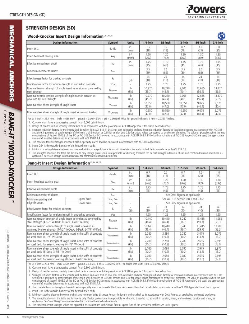
Wood-Knocker Insert Design Information1,2,3,4,5,6,7
Design Information Symbol Units 1/4-inch 3/8-inch 1/2-inch 5/8-inch 3/4-inch
Insert O.D. da (do) in.(mm)
0.7(18)
0.7(18)
0.7(18)
1.0(25)
1.0(25)
Insert head net bearing area Abrgin2
(mm2)1.20(762)
1.20(762)
1.20(762)
1.30(839)
1.30(839)
Effective embedment depth hefin.
(mm)1.75(45)
1.75(45)
1.75(45)
1.75(45)
1.75(45)
Minimum member thickness hmin - 3.5(89)
3.5(89)
3.5(89)
3.5(89)
3.5(89)
Effectiveness factor for cracked concrete kc-
(SI)24
(10)24
(10)24
(10)24
(10)24
(10)Modification factor for tension strength in uncracked concrete ΨC,N - 1.25 1.25 1.25 1.25 1.25Nominal tension strength of single insert in tension as governed by steel strength Nsa,insert
lb(kN)
10,270(45.7)
10,270(45.7)
9,005(40.1)
12,685(56.4)
13,370(59.5)
Nominal seismic tension strength of single insert in tension as governed by steel strength Nsa,insert,eq
lb(kN)
10,270(45.7)
10,270(45.7)
9,005(40.1)
12,685(56.4)
13,370(59.5)
Nominal steel shear strength of single insert Vsa,insertlb
(kN)10,550(47.0)
10,550(47.0)
10,550(47.0)
9,075(40.4)
9,075(40.4)
Nominal steel shear strength of single insert for seismic loading Vsa,insert,eqlb
(kN)10,550(47.0)
10,550(47.0)
10,550(47.0)
9,075(40.4)
9,075(40.4)
For SI: 1 inch = 25.4 mm, 1 inch2 = 635 mm2, 1 pound = 0.00445 kN, 1 psi = 0.006895 MPa. For pound-inch unit: 1 mm = 0.03937 inches.1. Concrete must have a compressive strength f'c of 2,500 psi minimum.2. Design of headed cast-in specialty inserts shall be in accordance with the provisions of ACI 318 Appendix D for cast-in headed anchors.3. Strength reduction factors for the inserts shall be taken from ACI 318-11 D.4.3 for cast-in headed anchors. Strength reduction factors for load combinations in accordance with ACI 318
Section 9.2 governed by steel strength of the insert shall be taken as 0.65 for tension and 0.60 for shear; values correspond to brittle steel elements. The value of f applies when the load combinations of Section 1605.2 of the IBC or ACI 318 Section 9.2 are used in accordance with ACI 318 D.4.3. If the load combinations of ACI 318 Appendix C are used, the appropriate value of f must be determined in accordance with ACI 318 D.4.4.
4. The concrete tension strength of headed cast-in specialty inserts shall be calculated in accordance with ACI 318 Appendix D.5. Insert O.D. is the outside diameter of the headed insert body.6. Minimum spacing distance between anchors and minimum edge distance for cast-in Wood-Knocker anchors shall be in accordance with ACI 318 D.8.7. The strengths shown in the table are for inserts only. Design professional is responsible for checking threaded rod or bolt strength in tension, shear, and combined tension and shear, as
applicable. See Steel Design Information table for common threaded rod elements.
Bang-It Insert Design Information1,2,3,4,5,6,7,8
Design Information Symbol Units 1/4-inch 3/8-inch 1/2-inch 5/8-inch 3/4-inch
Insert O.D. da (do) in.(mm)
0.7(18)
0.7(18)
0.7(18)
1.0(25)
1.0(25)
Insert head net bearing area Abrgin2
(mm2)1.20(762)
1.20(762)
1.20(762)
1.30(839)
1.30(839)
Effective embedment depth hefin.
(mm)1.75(45)
1.75(45)
1.75(45)
1.75(45)
1.75(45)
Minimum member thickness hmin - See Deck Figures as applicable
Minimum spacing and edge distances
Upper flute smin, cmin - See ACI 318 Section D.8.1 and D.8.2Lower flute smin, cmin - See Deck Figures as applicable
Effectiveness factor for cracked concrete kc-
(SI)24
(10)24
(10)24
(10)24
(10)24
(10)Modification factor for tension strength in uncracked concrete ΨC,N - 1.25 1.25 1.25 1.25 1.25Nominal tension strength of single insert in tension as governed by steel strength (4-1/2" W-Deck, B-Deck, 3-7/8" W-Deck) Nsa,insert
lb(kN)
10,440(46.4)
10,440(46.4)
8,240(36.7)
13,415(59.7)
11,985(53.3)
Nominal seismic tension strength of single insert in tension as governed by steel strength (4-1/2" W-Deck, B-Deck, 3-7/8" W-Deck) Nsa,insert,eq
lb(kN)
10,440(46.4)
10,440(46.4)
8,240(36.7)
13,415(59.7)
11,985(53.3)
Nominal steel shear strength of single insert in the soffit of concrete on steel deck, (4-1/2" W-Deck) Vsa,insert,deck
lb(kN)
2,280(10.2)
2,280(10.2)
2,280(10.2)
3,075(13.7)
3,075(13.7)
Nominal steel shear strength of single insert in the soffit of concrete on steel deck, for seismic loading, (4-1/2" W-Deck) Vsa,insert,deck,eq
lb(kN)
2,280(10.2)
2,280(10.2)
2,280(10.2)
2,695(12.0)
2,695(12.0)
Nominal steel shear strength of single insert in the soffit of concrete on steel deck, (B-Deck, 3-7/8" W-Deck) Vsa,insert,deck
lb(kN)
2,080(10.2)
2,080(10.2)
2,080(10.2)
2,975(13.2)
2,975(13.2)
Nominal steel shear strength of single insert in the soffit of concrete on steel deck, for seismic loading, (B-Deck, 3-7/8" W-Deck) Vsa,insert,deck,eq
lb(kN)
2,080(10.2)
2,080(10.2)
2,080(10.2)
2,695(12.0)
2,695(12.0)
For SI: 1 inch = 25.4 mm, 1 inch2 = 635 mm2, 1 pound = 4.45 N, 1 psi = 0.006895 MPa. For pound-inch unit: 1 mm = 0.03937 inches.1. Concrete must have a compressive strength f'c of 2,500 psi minimum.2. Design of headed cast-in specialty inserts shall be in accordance with the provisions of ACI 318 Appendix D for cast-in headed anchors.3. Strength reduction factors for the inserts shall be taken from ACI 318-11 D.4.3 for cast-in headed anchors. Strength reduction factors for load combinations in accordance with ACI 318
Section 9.2 governed by steel strength of the insert shall be taken as 0.65 for tension and 0.60 for shear; values correspond to brittle steel elements. The value of f applies when the load combinations of Section 1605.2 of the IBC or ACI 318 Section 9.2 are used in accordance with ACI 318 D.4.3. If the load combinations of ACI 318 Appendix C are used, the appropriate value of f must be determined in accordance with ACI 318 D.4.4.
4. The concrete tension strength of headed cast-in specialty inserts in concrete filled steel deck assemblies shall be calculated in accordance with ACI 318 Appendix D and Deck Figures.5. Insert O.D. is the outside diameter of the headed insert body.6. Minimum spacing distance between anchors and minimum edge distances for cast-in Bang-It anchors shall be in accordance with Deck Figures, as applicable, and noted provisions.7. The strengths shown in the table are for inserts only. Design professional is responsible for checking threaded rod strength in tension, shear, and combined tension and shear, as
applicable. See Steel Design Information table for common threaded rod elements.8. The tabulated insert strength values are applicable to installations in the lower flute or upper flute of the steel deck profiles; see Deck Figures.

www.powers.com 7
STReNGTH DeSIGN (SD)
TECH
MAN
UAL
– M
ECHA
NIC
AL A
NCH
ORS
©20
15 P
OW
ERS
VO
LUM
E 1
– 9/
2015
– R
EV. E
Mech
an
ica
l a
nch
or
sWood-Knocker Insert Installed in Soffit of Form Pour Concrete Floor and Roof Assemblies
Min. Thick hef
Wood-Knocker Insert (Typ)
Normal Weight Concrete Or Lightweight Concrete (Minimum 2,500 PSI)
Bang-It Inserts Installed in Soffit of Concrete Filled Steel Deck Floor and Roof Assemblies, 4-1/2 -inch W-Deck1,2,3,4
Min. Thick.
Max. 3"
Min. 4-1/2"(Typ)
Upper Flute (Valley) Min.
1-1/8"
Lower Flute (Ridge)
No. 22 Gauge Steel Deck Min.
Sand-lightweight Concrete Or Normal Weight Concrete Over Steel Deck (Minimum 3,000 PSI)
Bang-It Insert (Typ)
Flute Edge
hef
Min. 4-1/2"(Typ)
Min. 12"(Typ)
Bang-It Inserts Installed in Soffit of Concrete Filled Steel Deck Floor and Roof Assemblies, B-Deck1,2,3,4,5,6,7
Min.Thick
1-1/2"
Min. 1-3/4"(Typ)
Max. 3-1/2" (Typ)
Lower Flute (Ridge)
No. 22 Gauge Steel Deck Min.
Upper Flute (Valley)
Min. 2-1/2" (Typ)
Flute Edge
Min. 3/4"
Bang-It Insert (Typ)
6" C.C. (Typ)
Sand-lightweight Concrete Or Normal Weight Concrete Over Steel Deck (Minimum 3,000 PSI)
hef
Bang-It Inserts Installed in Soffit of Concrete Filled Steel Deck Floor and Roof Assemblies, 3-7/8 -inch W-Deck1,2,3,8
Min. Thick.
3"
Min. 3-7/8"(Typ)
Upper Flute
(Valley)
Min. 3/4"
Lower Flute (Ridge)
No. 22 Gauge Steel Deck Min.
Bang-It Insert (Typ)
Flute Edge
hef
Min. 3-7/8"(Typ)
Sand-lightweight Concrete Or Normal Weight Concrete Over Steel Deck (Minimum 3,000 PSI)
Min. 12"(Typ)
1. Inserts may be placed in the upper flute or lower flute of the steel deck assembly. Inserts in the lower flute require a minimum 1.5" of concrete topping thickness (min. thick) from the top of the deck at the location of the installation. Upper flute installations require a minimum 3" topping thickness concrete (min. thick) from the top of the deck at the location of the installation.
2. Axial spacing for Bang-It inserts along the flute length shall be minimum 3hef.3. Upper flute Bang-It inserts are not subject to steel deck dimension limitations, or the minimum steel deck gauge limitations.4. Inserts in the lower flute of 4-1/2-inch W-Deck may be installed with a maximum 1-1/8 -inch offset in either direction from the center of the flute. The offset distance may be increased for flute
widths greater than those shown provided the minimum lower flute edge distance of 1-1/8 -inch is also satisfied.5. Inserts in the lower flute of B-Deck may be installed with a maximum 1/8 -inch offset in either direction from the center of the flute. The offset distance may be increased for flute widths
greater than those shown provided the minimum lower flute edge distance of 3/4 -inch is also satisfied.6. Lower flute installations of B-Deck with flutes widths greater than 1-3/4 -inch are permitted.7. Lower flute installations of B-Deck in flute depths greater than 1-1/2 -inch are permitted provided the minimum edge distance of 3/4 -inch is met and the minimum lower flute width is
increased proportionally (e.g. applicable to a lower flute depth of 2-inch with a minimum lower flute width of 2-1/4 -inch).8. Inserts in the lower flute of 3-7/8-inch W-Deck may be installed with a maximum 1-3/16 -inch offset in either direction from the center of the flute.

www.powers.com 8
TECH MAN
UAL – MECHAN
ICAL ANCHO
RS ©2015 PO
WERS VO
LUME 1 – 9/2015 – REV. E
STReNGTH DeSIGN (SD)
Mech
an
ica
l a
nch
or
s
Specifications And Physical Properties Of Common Carbon Steel Threaded Rod Elements1
Threaded Rod Specification Units
Min. SpecifiedUltimateStrength,
Futa
Min. Specified Yield Strength
0.2 Percent Offset, Fya
Futa
-Fya
ElongationMinimum Percent5
Reduction Of Area
Min. Percent
Related NutSpecification6
CarbonSteel
ASTM A36/A36M2 andF15543 Grade 36
psi(MPa)
58,000(400)
36,000(248) 1.61 23 40
(50 for A36)ASTM A194 / A563 Grade A
ASTM F15543
Grade 105psi
(MPa)125,000
(862)105,000
(724) 1.19 15 45ASTM A194 /
A563 Grade DHASTM A193/A193M4
Grade B7psi
(MPa)125,000
(860)105,000
(720) 1.19 16 50
For SI: 1 inch = 25.4 mm, 1 psi = 0.006897 MPa. For pound-inch units: 1 mm = 0.03937 inch, 1 MPa = 145.0 psi.1. Inserts may be used in conjunction with all grades of continuously threaded carbon steels (all-thread) that comply with code reference standards and that have thread characteristics
comparable with ANSI B1.1 UNC Coarse Thread Series.2. Standard Specification for Carbon Structural Steel.3. Standard Specification for Anchor Bolts, Steel, 36, 55, and 105-ksi Yield Strength.4. Standard Specification for Alloy-Steel and Stainless Steel Bolting Materials for High Temperature or High Pressure Service and Other Special Purpose Applications.5. Based on 2-inch (50 mm) gauge length except ASTM A193, which are based on a gauge length of 4d (drod).6. Where nuts are applicable, nuts of other grades and style having specified proof load stress greater than the specified grade and style are also suitable.
Steel Design Information For Common Threaded Rod Elements Used With Concrete Inserts1,2,3,4
Design Information Symbol Units 1/4-inch 3/8-inch 1/2-inch 5/8-inch 3/4-inch
Threaded rod nominal outside diameter drodin.
(mm)0.250(6.4)
0.375(9.5)
0.500(12.7)
0.625(15.9)
0.750(19.1)
Threaded rod effective cross-sectional area Asein2
(mm2)0.032(21)
0.078(50)
0.142(92)
0.226(146)
0.335(216)
Nominal tension strength of ASTM A36 threaded rod in tension as governed by steel strength Nsa,rod,A36
lb(kN)
1,855(8.2)
4,525(20.0)
8,235(36.6)
13,110(58.3)
19,430(86.3)
Nominal seismic tension strength of ASTM A36 threaded rod tension as governed by steel strength Nsa,rod,A36,eq
lb(kN)
1,855(8.2)
4,525(20.0)
8,235(36.6)
13,110(58.3)
19,430(86.4)
Nominal tension strength of ASTM A193, Gr. B7 threaded rod in tension as governed by steel strength Nsa,rod,B7
lb(kN)
4,000(17.7)
9,750(43.1)
17,750(78.9)
28,250(125.7)
41,875(186.0)
Nominal seismic tension strength of ASTM A193, Gr. B7 threaded rod tension as governed by steel strength Nsa,rod,B7,eq
lb(kN)
4,000(17.7)
9,750(43.1)
17,750(78.9)
28,250(125.7)
41,875(186.0)
Nominal shear strength of ASTM A36 threaded rod in shear as governed by steel strength Vsa,rod,A36
lb(kN)
1,115(4.9)
2,715(12.1)
4,940(22.0)
7,865(35.0)
11,660(51.9)
Nominal seismic shear strength of ASTM A36 threaded rod in shear as governed by steel strength Vsa,rod,A36,eq
lb(kN)
780(3.5)
1,900(8.4)
3,460(15.4)
5,505(24.5)
8,160(36.3)
Nominal shear strength of ASTM A193, Gr. B7 threaded rod in shear as governed by steel strength Vsa,rod,B7
lb(kN)
2,385(10.6)
5,815(25.9)
10,640(7.3)
16,950(75.4)
25,085(111.6)
Nominal seismic shear strength of ASTM A193, Gr. B7 threaded rod in shear as governed by steel strength Vsa,rod,B7,eq
lb(kN)
1,680(7.5)
4,095(18.2)
7,455(34.2)
11,865(52.8)
17,590(78.2)
For SI: 1 inch = 25.4 mm, 1 pound = 0.00445 kN, 1 in2 = 645.2 mm2. For pound-inch unit: 1 mm = 0.03937 inches.1. Values provided for steel element material types based on minimum specified strengths and calculated in accordance with ACI 318-11 Eq. (D-2) and Eq. (D-29).2. fNsa shall be the lower of the fNsa,rod or fNsa,insert for static steel strength in tension; for seismic loading fNsa,eq shall be the lower of the fNsa,rod,eq or fNsa,insert,eq.3. fVsa shall be the lower of the fVsa,rod or fVsa,insert for static steel strength in tension; for seismic loading fVsa,eq shall be the lower of the fVsa,rod,eq or fVsa,insert,eq.4. Strength reduction factors shall be taken from ACI 318-11 D.4.3 for steel elements. Strength reduction factors for load combinations in accordance with ACI 318 Section 9.2 governed
by steel strength shall be taken as 0.75 for tension and 0.70 for shear for ductile steel elements; values correspond to ductile steel elements. The value off applies when the load combinations of Section 1605.2 of the IBC or ACI 318 Section 9.2 are used in accordance with ACI 318 D.4.3. If the load combinations of ACI 318 Appendix C are used, the appropriate value of f must be determined in accordance with ACI 318 D.4.4.
www.powers.com 9
STReNGTH DeSIGN (SD)
TECH
MAN
UAL
– M
ECHA
NIC
AL A
NCH
ORS
©20
15 P
OW
ERS
VO
LUM
E 1
– 9/
2015
– R
EV. E
Mech
an
ica
l a
nch
or
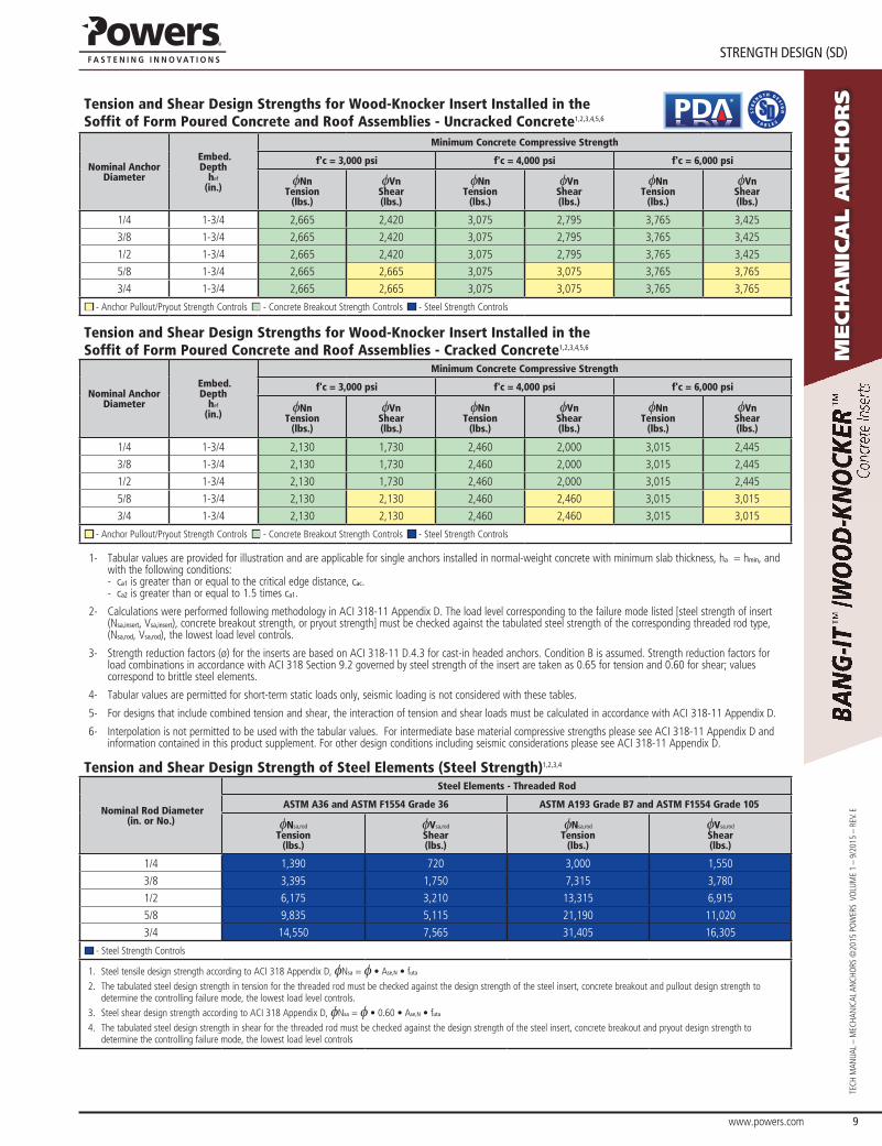
sTension and Shear Design Strengths for Wood-Knocker Insert Installed in the Soffit of Form Poured Concrete and Roof Assemblies - Uncracked Concrete1,2,3,4,5,6
®
Nominal Anchor Diameter
Embed.Depth
hef
(in.)
Minimum Concrete Compressive Strength
f'c = 3,000 psi f'c = 4,000 psi f'c = 6,000 psi
fNnTension
(lbs.)
fVnShear(lbs.)
fNnTension
(lbs.)
fVnShear(lbs.)
fNnTension
(lbs.)
fVnShear(lbs.)
1/4 1-3/4 2,665 2,420 3,075 2,795 3,765 3,425
3/8 1-3/4 2,665 2,420 3,075 2,795 3,765 3,425
1/2 1-3/4 2,665 2,420 3,075 2,795 3,765 3,425
5/8 1-3/4 2,665 2,665 3,075 3,075 3,765 3,765
3/4 1-3/4 2,665 2,665 3,075 3,075 3,765 3,765
■ - Anchor Pullout/Pryout Strength Controls ■ - Concrete Breakout Strength Controls ■ - Steel Strength Controls
Tension and Shear Design Strengths for Wood-Knocker Insert Installed in the Soffit of Form Poured Concrete and Roof Assemblies - Cracked Concrete1,2,3,4,5,6
Nominal Anchor Diameter
Embed.Depth
hef
(in.)
Minimum Concrete Compressive Strength
f'c = 3,000 psi f'c = 4,000 psi f'c = 6,000 psi
fNnTension
(lbs.)
fVnShear(lbs.)
fNnTension
(lbs.)
fVnShear(lbs.)
fNnTension
(lbs.)
fVnShear(lbs.)
1/4 1-3/4 2,130 1,730 2,460 2,000 3,015 2,445
3/8 1-3/4 2,130 1,730 2,460 2,000 3,015 2,445
1/2 1-3/4 2,130 1,730 2,460 2,000 3,015 2,445
5/8 1-3/4 2,130 2,130 2,460 2,460 3,015 3,015
3/4 1-3/4 2,130 2,130 2,460 2,460 3,015 3,015
■ - Anchor Pullout/Pryout Strength Controls ■ - Concrete Breakout Strength Controls ■ - Steel Strength Controls
1- Tabular values are provided for illustration and are applicable for single anchors installed in normal-weight concrete with minimum slab thickness, ha = hmin, and with the following conditions: - ca1 is greater than or equal to the critical edge distance, cac. - ca2 is greater than or equal to 1.5 times ca1.
2- Calculations were performed following methodology in ACI 318-11 Appendix D. The load level corresponding to the failure mode listed [steel strength of insert (Nsa,insert, Vsa,insert), concrete breakout strength, or pryout strength] must be checked against the tabulated steel strength of the corresponding threaded rod type, (Nsa,rod, Vsa,rod), the lowest load level controls.
3- Strength reduction factors (ø) for the inserts are based on ACI 318-11 D.4.3 for cast-in headed anchors. Condition B is assumed. Strength reduction factors for load combinations in accordance with ACI 318 Section 9.2 governed by steel strength of the insert are taken as 0.65 for tension and 0.60 for shear; values correspond to brittle steel elements.
4- Tabular values are permitted for short-term static loads only, seismic loading is not considered with these tables.
5- For designs that include combined tension and shear, the interaction of tension and shear loads must be calculated in accordance with ACI 318-11 Appendix D.
6- Interpolation is not permitted to be used with the tabular values. For intermediate base material compressive strengths please see ACI 318-11 Appendix D and information contained in this product supplement. For other design conditions including seismic considerations please see ACI 318-11 Appendix D.
Tension and Shear Design Strength of Steel Elements (Steel Strength)1,2,3,4
Nominal Rod Diameter(in. or No.)
Steel Elements - Threaded Rod
ASTM A36 and ASTM F1554 Grade 36 ASTM A193 Grade B7 and ASTM F1554 Grade 105
fNsa,rod
Tension(lbs.)
fVsa,rod
Shear(lbs.)
fNsa,rod
Tension(lbs.)
fVsa,rod
Shear(lbs.)
1/4 1,390 720 3,000 1,550
3/8 3,395 1,750 7,315 3,780
1/2 6,175 3,210 13,315 6,915
5/8 9,835 5,115 21,190 11,020
3/4 14,550 7,565 31,405 16,305
■ - Steel Strength Controls
1. Steel tensile design strength according to ACI 318 Appendix D, fNsa = f • Ase,N • futa
2. The tabulated steel design strength in tension for the threaded rod must be checked against the design strength of the steel insert, concrete breakout and pullout design strength to determine the controlling failure mode, the lowest load level controls.
3. Steel shear design strength according to ACI 318 Appendix D, fNsa = f • 0.60 • Ase,N • futa
4. The tabulated steel design strength in shear for the threaded rod must be checked against the design strength of the steel insert, concrete breakout and pryout design strength to determine the controlling failure mode, the lowest load level controls

www.powers.com 10
TECH MAN
UAL – MECHAN
ICAL ANCHO
RS ©2015 PO
WERS VO
LUME 1 – 9/2015 – REV. E
STReNGTH DeSIGN (SD)
Mech
an
ica
l a
nch
or
s
Tension and Shear Design Strengths for Bang-It Inserts Installed in the Soffit of Uncracked Concrete Filled Steel Deck Floor and Roof Assemblies1,2,3,4,5,6
®
Nominal Anchor
Diameter
Embed.Depth
hef
(in.)
Minimum Concrete Compressive Strength
f'c = 3,000 psi
4-1/2" W-Deck B-Deck 3-7/8" W-Deck
Upper Flute Lower Flute Upper Flute Lower Flute Upper Flute Lower Flute
fNnTension
(lbs.)
fVnShear(lbs.)
fNnTension
(lbs.)
fVnShear(lbs.)
fNnTension
(lbs.)
fVnShear(lbs.)
fNnTension
(lbs.)
fVnShear(lbs.)
fNnTension
(lbs.)
fVnShear(lbs.)
fNnTension
(lbs.)
fVnShear(lbs.)
1/4 1-3/4 2,665 1,370 1,340 1,370 2,265 1,250 595 1,250 2,265 1,250 1,145 1,2503/8 1-3/4 2,665 1,370 1,340 1,370 2,265 1,250 595 1,250 2,265 1,250 1,145 1,2501/2 1-3/4 2,665 1,370 1,340 1,370 2,265 1,250 595 1,250 2,265 1,250 1,145 1,2505/8 1-3/4 2,665 1,845 1,340 1,845 2,265 1,785 595 1,785 2,265 1,785 1,145 1,7853/4 1-3/4 2,665 1,845 1,340 1,845 2,265 1,785 595 1,785 2,265 1,785 1,145 1,785
■ - Anchor Pullout/Pryout Strength Controls ■ - Concrete Breakout Strength Controls ■ - Steel Strength Controls
Tension and Shear Design Strengths for Bang-It Inserts Installed in the Soffit of Cracked Concrete Filled Steel Deck Floor and Roof Assemblies1,2,3,4,5,6
Nominal Anchor
Diameter
Embed.Depth
hef
(in.)
Minimum Concrete Compressive Strength
f'c = 3,000 psi
4-1/2" W-Deck B-Deck 3-7/8" W-Deck
Upper Flute Lower Flute Upper Flute Lower Flute Upper Flute Lower Flute
fNnTension
(lbs.)
fVnShear(lbs.)
fNnTension
(lbs.)
fVnShear(lbs.)
fNnTension
(lbs.)
fVnShear(lbs.)
fNnTension
(lbs.)
fVnShear(lbs.)
fNnTension
(lbs.)
fVnShear(lbs.)
fNnTension
(lbs.)
fVnShear(lbs.)
1/4 1-3/4 1,810 1,370 1,070 1,370 1,810 1,250 475 1,250 1,810 1,250 915 1,2503/8 1-3/4 1,810 1,370 1,070 1,370 1,810 1,250 475 1,250 1,810 1,250 915 1,2501/2 1-3/4 1,810 1,370 1,070 1,370 1,810 1,250 475 1,250 1,810 1,250 915 1,2505/8 1-3/4 1,810 1,845 1,070 1,845 1,810 1,785 475 1,785 1,810 1,785 915 1,7853/4 1-3/4 1,810 1,845 1,070 1,845 1,810 1,785 475 1,785 1,810 1,785 915 1,785
■ - Anchor Pullout/Pryout Strength Controls ■ - Concrete Breakout Strength Controls ■ - Steel Strength Controls
1- Tabular values are provided for illustration and are applicable for single anchors installed in sand-lightweight concrete with minimum slab thickness, ha = hmin, and with the following conditions: - ca1 is greater than or equal to the critical edge distance, cac. - ca2 is greater than or equal to 1.5 times ca1.
2- Calculations were performed following methodology in ACI 318-11 Appendix D. The load level corresponding to the failure mode listed [steel strength of insert (Nsa,insert, Vsa,insert), concrete breakout strength, or pryout strength] must be checked against the tabulated steel strength of the corresponding threaded rod type, (Nsa,rod, Vsa,rod), the lowest load level controls.
3- Strength reduction factors (ø) for the inserts are based on ACI 318-11 D.4.3 for cast-in headed anchors. Condition B is assumed. Strength reduction factors for load combinations in accordance with ACI 318 Section 9.2 governed by steel strength of the insert are taken as 0.65 for tension and 0.60 for shear; values correspond to brittle steel elements.
4- Tabular values are permitted for short-term static loads only, seismic loading is not considered with these tables.
5- For designs that include combined tension and shear, the interaction of tension and shear loads must be calculated in accordance with ACI 318-11 Appendix D.
6- Interpolation is not permitted to be used with the tabular values. For intermediate base material compressive strengths please see ACI 318-11 Appendix D and information contained in this product supplement. For other design conditions including seismic considerations please see ACI 318-11 Appendix D.
Tension and Shear Design Strength of Steel Elements (Steel Strength)1,2,3,4
Nominal Rod Diameter(in.)
Steel Elements - Threaded Rod
ASTM A36 and ASTM F1554 Grade 36 ASTM A193 Grade B7 and ASTM F1554 Grade 105
fNsa,rod
Tension(lbs.)
fVsa,rod
Shear(lbs.)
fNsa,rod
Tension(lbs.)
fVsa,rod
Shear(lbs.)
1/4 1,390 720 3,000 1,5503/8 3,395 1,750 7,315 3,7801/2 6,175 3,210 13,315 6,9155/8 9,835 5,115 21,190 11,0203/4 14,550 7,565 31,405 16,305
■ - Steel Strength Controls
1. Steel tensile design strength according to ACI 318 Appendix D, fNsa = f • Ase,N • futa
2. The tabulated steel design strength in tension for the threaded rod must be checked against the design strength of the steel insert, concrete breakout and pullout design strength to determine the controlling failure mode, the lowest load level controls.
3. Steel shear design strength according to ACI 318 Appendix D, fNsa = f • 0.60 • Ase,N • futa
4. The tabulated steel design strength in shear for the threaded rod must be checked against the design strength of the steel insert, concrete breakout and pryout design strength to determine the controlling failure mode, the lowest load level controls.

www.powers.com 11
oRDeRING INFoRMATIoN
TECH
MAN
UAL
– M
ECHA
NIC
AL A
NCH
ORS
©20
15 P
OW
ERS
VO
LUM
E 1
– 9/
2015
– R
EV. E
Mech
an
ica
l a
nch
or
sIdealization of Concrete Filled Steel Decks for Determination of Concrete Breakout Strength in Accordance with ACI 318
Steel Deck
Bang-It Insert (Typ)
Threaded Rod (Typ)Ca,min
Ncb
ANCO
ANCO
ANC
ANC
Steel Deck
Bang-It Insert (Typ)
Threaded Rod (Typ)
Ncb
ANCO
ANC
ANCO
Ca,min
ANC
Idealization of Standard Steel Deck Profiles Idealization of B-Deck Steel Deck Profiles
orderIng InFormatIon
Bang-It Deck Insert (UNC) Cat.No. Description Color Code Pre-Drilled Hole Std. Box Std. Pallet
7540 1/4" Bang-It Brown 13/16" or 7/8" 100 4,000
7542 3/8" Bang-It Green 13/16" or 7/8" 100 4,000
7544 1/2" Bang-It yellow 13/16" or 7/8" 100 4,000
7546 5/8" Bang-It Red 1-3/16" or 1-1/4" 50 2,400
7548 3/4" Bang-It Purple 1-3/16" or 1-1/4" 50 2,400
Bang-It Installation AccessoriesCat.No. Description Std. Box
7560 Bang-It Stand Up Pole tool 1
7562 13/16" Carbide Hole Saw for 1/4", 3/8" and 1/2" sizes 1
7564 1-3/16" Carbide Hole Saw for 5/8", 3/4" and 7/8" sizes 1
7566 Extra Carbide Hole Saw Center Bit 1
Wood-Knocker Form Insert (UNC)Cat No. Description Color Code Std. Box Std. Pallet
7550 1/4" Wood-Knocker Brown 200 9,600
7552 3/8" Wood-Knocker Green 200 9,600
7554 1/2" Wood-Knocker yellow 200 9,600
7556 5/8" Wood-Knocker Red 150 6,000
7558 3/4" Wood-Knocker Purple 150 6,000
Threaded Inserts are color coded to easily identify location and diameter of the internally threaded coupling, allowing multiple trades on the same job to suspend their systems with various size steel threaded rods.