Embed Size (px)
Citation preview

Chapter 4 - 1
Karadeniz Teknik ÜniversitesiElektrik-Elektronik Mühendisliği Bölümü
61080 Trabzon
Chapter 4 - 2
Overvoltages in Power SystemsOvervoltages in Power Systems

Chapter 4 - 3
• Examination of overvoltages on the power system includes a study of their magnitudes, shapes, durations, and frequency of occurrence.
• The study should be performed at all points along the transmission network to which the surges may travel.
INTRODUCTION
Overvoltages in Power Systems
Chapter 4 - 4
TYPES OF OVERVOLTAGE• The voltage stresses on transmission network insulation are found
to have a variety of Origins. • In normal operation AC (or DC) voltages do not stress the insulation
severely. • Over voltage stressing a power system can be classified into two
main types:
1-External overvoltage: generated by atmospheric disturbances of these disturbances, lightning is the most common and the most severe.
2. Internal overvoltages: generated by changes in the operating conditions of the network. Internal over voltages can be divided into (a) switching overvoltages and (b) temporary overvoltages.
Overvoltages in Power Systems

Chapter 4 - 5
LIGHTNING OVERVOLTAGES
Lightning is produced in an attempt by nature to maintain a dynamic balance between the positively charged ionosphere and the negatively charged earth.
Over fair-weather areas there is a downward transfer of positive charges through the global air-earth current.
This is then counteracted by thunderstorms, during which positive charges are transferred upward in the form of lightning.
During thunderstorms, positive and negative charges are separated by the movements of air currents forming ice crystals in the upper layer of a cloud and rain in the lower part.
Overvoltages in Power Systems
Chapter 4 - 6
The cloud becomes negatively charged and has a larger layer of positive charge at its top.
As the separation of charge proceeds in the cloud, the potential difference between the centers of charges' increases and the vertical electric field along the cloud also increases.
The total potential difference between the two main charge centers may vary from l00 to 1000 MV.
Only a part of the total charge-several hundred coulombs-is released to earth by lightning; the rest is consumed in inter-cloud discharges.
The height of the thundercloud dipole above earth may reach 5 km in tropical regions.
LIGHTNING OVERVOLTAGES
Overvoltages in Power Systems

Chapter 4 - 7
Overvoltages in Power Systems
LIGHTNING OVERVOLTAGES
Chapter 4 - 8
LIGHTNING OVERVOLTAGES
Stepped LeaderStepped Leader
Overvoltages in Power Systems

Chapter 4 - 9
LIGHTNING OVERVOLTAGES
Overvoltages in Power Systems
Streamers
Chapter 4 - 10
Overvoltages in Power Systems
STANDARD IMPULSE WAVE

Chapter 4 - 11
Overvoltages in Power Systems
The channel to earth is first established by a stepped dischargecalled a leader stroke.
The leader is initiated by a breakdown between polarized water droplets at the cloud base caused by the high electric field, or a discharge between the negative charge mass in the lower cloud and the positive charge pocket below it. (Figure 14.1)
As the downward leader approaches the earth, an upward leader begins to proceed from earth before the former reaches earth.
The upward leader joins the downward one at a point referred to as the striking point.
This is the start of the return stroke, which progresses upward like a travelling wave on a transmission line.
The Lightning Discharge
Chapter 4 - 12
Overvoltages in Power Systems
LIGHTNING PHENOMENON

Chapter 4 - 13
Overvoltages in Power Systems
At the earthing point a heavy impulse current reaching the order of tens of kilo amperes occurs, which is responsible for the known damage of lightning.
The velocity of progression of the return stoke is very high and may reach half the speed of light.
The corresponding current heats its path to temperatures up to 20,000°C, causing the explosive air expansion that is heard as thunder.
The current pulse rises to its crest in a few micro seconds and decays over a period of tens or hundreds of microseconds.
LIGHTNING PHENOMENON
Chapter 4 - 14
Overvoltages in Power Systems
Facts about Lightning
A strike can average 100 million volts of electricity
Current of up to 100,000 amperes
Can generate 54,000 oF
Lightning strikes somewhere on the Earth every second
Kills hundreds of people every year.

Chapter 4 - 15
Overvoltages in Power Systems
What Does This Mean?
Lightning can strike ground up to ten miles from a storm
There is an average of 2-3 miles between strikes
So how can we tell how far away lightning has struck?
Chapter 4 - 16
Overvoltages in Power Systems
Use The Five Second Rule
Light travels at about 186,291 miles/second
Sound travels at only 1,088 feet/second
You will see the flash of lightning almost immediately
5280/1088= 4.9
About 5 seconds for sound to travel 1 mile
1 miles (statute) is equal to 1,609.34 meters.
1 feet is equal to 0.30 meters.

Chapter 4 - 17
Overvoltages in Power Systems
Four Main Features of Lightning Protection
1) Air terminal
2) Conductors
3) Ground termination
4) Surge protection
Chapter 4 - 18
Overvoltages in Power Systems
Lightning Step Voltage
200,000 Volts
0 Volts far away
Current flow
thru earthgenerates
voltage
8,000 voltsacross feet(Typical)
Step Voltage

Chapter 4 - 19
Overvoltages in Power Systems
Frequency of occurrence of lightning flashes
A knowledge of the frequency of occurrence of lightning strokes is importance in the design of protection against lightning.
The frequency of occurrence is defined as the flashes occurring per unit area per year.
The isokeraunic level at any location can be quite easily determined.
The isokeraunic level is defined as the number of days in the year on which thunder is heard.
It does not distinguish between whether lightning was heard only once during the day or whether there was a long thunderstorm.
Isokeraunic : (line on map connecting places) with equal or simultaneous occurrence of thunderstorms.
Chapter 4 - 20
Overvoltages in Power Systems
It has been found hat the isokeraunic level is linearly related to the number of flashes per unit area per year.
The isokeraunic level for Egypt is 0.3-1 flashes/km2/year.
The number of Thunderstorm Days/Year in Egypt is in Egypt is 1010--31 31 days.days.
It is now possible to obtain the frequency of occurrence of lightning in any given region quite easily.
The isokeraunic map shows contours of equal isokerauniclevel.
Frequency of occurrence of lightning flashes

Chapter 4 - 21
Overvoltages in Power Systems
Chapter 4 - 22
Overvoltages in Power Systems
Lightning Voltage Surges
The most severe lightning stroke is that which strikes a phase conductor on the transmission line
It produces the highest overvoltage for a given stroke current.
The lightning stroke injects its current into a termination impedance Z, which in this case is half the line surge impedance Zosince the current will flow in both directions as shown in Figure 14.2. Therefore, the voltage surge magnitude at the striking point is
V =( ½)IZo (1)
The lightning current magnitude is rarely less than 10 kA.
For typical overhead line surge impedance Zo of 300 Ω, the lightning surge voltage will probably have a magnitude in excess of 1500 kV.

Chapter 4 - 23
Overvoltages in Power Systems
EFFECT OF LIGHTNING
Chapter 4 - 24
Overvoltages in Power Systems
EFFECT OF LIGHTNING
Equation (1) assumes that the impedance of the lightning channelitself is much larger than 1/2Zo (it is believed to range from l00 to 3000 Ω).
Equation (1) indicates that the lightning voltage surge will have the same shape characteristics.
In practice the shapes and magnitudes of lightning surge waves get modified by their reflections at points of discontinuity as they travel along transmission lines.
Lightning strokes represent true danger to life, structures, power systems, and communication networks.
Lightning is always a major source of damage to power systems where equipment insulation may break down, under the resulting overvoltage and the subsequent high-energy discharge.

Chapter 4 - 25
SWITCHING OVERVOLTAGES
With the increase in transmission voltages needed to fulfil the required increase in transmitted powers, switching surges have become the governing factor in the design of insulation for EHV and UHV systems.
In the meantime, lightning overvoltages come as a secondary factor in these networks.
There are two fundamental reasons for this shift in relative importance from lightning to switching surges as higher transmission voltages are called for:
Overvoltages in Power Systems
Chapter 4 - 26
1. Overvoltages produced on transmission lines by lightning strokes are only slightly dependent on the power system voltages.
As a result, their magnitudes relative to the system peak voltage decrease as the latter is increased.
2. External insulation has its lowest breakdown strength under surges whose fronts fall in the range 50-500 micro sec., which is typical for switching surges.
3. According to the International Electro-technical Commission (IEC) recommendations, all equipment designed for operating voltages above 300 kV should be tested under switching impulses (i.e., laboratory-simulated switching surges).
SWITCHING OVERVOLTAGES
Overvoltages in Power Systems

Chapter 4 - 27
Origin of Switching Overvoltages
1. Energization of transmission lines and cables.
The following specific switching operations are some of the most common in this category:
a. Energization of a line that is open circuited at the far end
b. Energization of a line that is terminated by an unloaded transformer
c. Energization of a line through the low-voltage side of a transformer
There is a great variety of events that would initiate a switching surge in a power network.The switching operations of greatest relevance to insulation
design can be classified as follows:
Overvoltages in Power Systems
Chapter 4 - 28
2. Reenergization of a line. This means the energization of transmission line carrying charges trapped by previous line interruptions when high-speed reclosures are used.
Origin of Switching Overvoltages
3. Load rejection. This is affected by a circuit breaker opening at the far end of the line.
This may also be followed by opening the line at the sending end in what is called a line dropping operation.
Overvoltages in Power Systems

Chapter 4 - 29
4. Switching on and off of equipment. All switching operations involving an element of the transmission network will produce a switching surge.
a. Switching of high-voltage reactors b. Switching of transformers that are loaded by a reactor
on their tertiary winding c. Switching of a transformer at no load
Origin of Switching Overvoltages
5. Fault initiation and clearing.
Overvoltages in Power Systems
Chapter 4 - 30
Some important switching operations which can lead to switching overvoltages
1-Line energization
2-Reclosing (energization of a line with trapped charges)
3-low voltage side Energization of a line
4- Energization a line terminated by an unloaded transformer
5- Load rejection at the receiving end of a line
6- Load rejection at the receiving end of a line followed by line dropping at the sending end
Overvoltages in Power Systems
Chapter 4 - 31
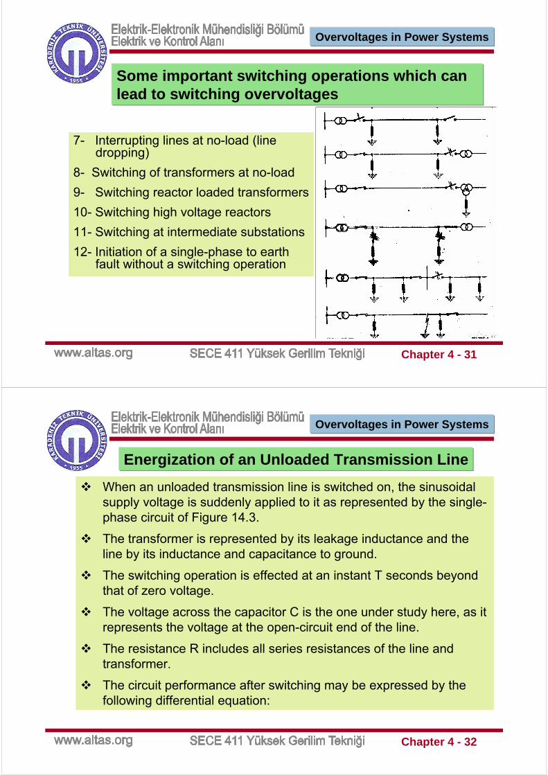
7- Interrupting lines at no-load (line dropping)
8- Switching of transformers at no-load
9- Switching reactor loaded transformers
10- Switching high voltage reactors
11- Switching at intermediate substations
12- Initiation of a single-phase to earth fault without a switching operation
Some important switching operations which can lead to switching overvoltages
Overvoltages in Power Systems
Chapter 4 - 32
Energization of an Unloaded Transmission Line
When an unloaded transmission line is switched on, the sinusoidal supply voltage is suddenly applied to it as represented by the single-phase circuit of Figure 14.3.
The transformer is represented by its leakage inductance and theline by its inductance and capacitance to ground.
The switching operation is effected at an instant T seconds beyond that of zero voltage.
The voltage across the capacitor C is the one under study here, as it represents the voltage at the open-circuit end of the line.
The resistance R includes all series resistances of the line andtransformer.
The circuit performance after switching may be expressed by the following differential equation:
Overvoltages in Power Systems

Chapter 4 - 33
Energization of an Unloaded Transmission Line
Overvoltages in Power Systems
Chapter 4 - 34
The supply voltage The supply voltage vvss(t(t) beyond the switching instant is:) beyond the switching instant is:
Energization of an Unloaded Transmission Line
Overvoltages in Power Systems

Chapter 4 - 35
Example
Energization of an Unloaded Transmission Line
Atypical 132/500 kV, 200 MVA transformer would have an inductance (referred to its 500 kV side) of about 400 mH; a 500 kV transmission line may have a series inductance of about 1 mH/km and a capacitance to ground of about 0.015 µF /km.
For a transmission line of 100 km, the total series inductance L of Figure 14.3 would be 500 mH and the capacitance C would be 1.5 µF.
Neglecting all series resistances (i.e., letting a = 0), the frequency of oscillation of the transient voltage component as given in equation (14.4) would be
Overvoltages in Power Systems
Chapter 4 - 36
Example
Energization of an Unloaded Transmission Line
Overvoltages in Power Systems

Chapter 4 - 37
TEMPORARYOVERVOLTAGES
Temporary overvoltages (sustained overvoltages) differ from transient switching overvoltages in that they last for longer durations, typically from a few cycles to a few seconds.
They take the form of undamped or slightly damped oscillations at a frequency equal or close to the power frequency.
The classification of temporary overvoltages as distinct from transient switching overvoltages is due mainly to the fact that the responses of power network insulation and surge arresters to their wave shapes are different.
Overvoltages in Power Systems
Chapter 4 - 38
Events leading to the generation of temporary overvoltages
When a transmission line or a large inductive load that is fed from a power station is suddenly switched off, the generator will speed up and the bus bar voltage will rise.
The amplitude of the overvoltage can be evaluated approximately, as illustrated in Figure 14.4, by
Load Rejection:
Overvoltages in Power Systems

Chapter 4 - 39
Load Rejection:
where E is the voltage behind the transient reactance, which is assumed to be constant over the subtransientperiod and equal to its value before the incident, Xs the transient reactance of the generator in series with the transformer reactance, and Xc the equivalent capacitive input reactance of the system.
V = E( Xc / (Xc –Xs))
Overvoltages in Power Systems
Chapter 4 - 40
Ferranti Effect
The Ferranti effect on an uncompensated transmission line is given by:
Where Vr and Vs are the receiving end and sending end voltages, respectively, and ℓ is the line length (km).
β0 is the phase shift constant of the line per unit length.
It is equal to the imaginary part of √ZY, where Z and Y are the impedance and admittance of the line per unit length.
For a lossless line β0 = ω√IC where L and C are the inductance and capacitance of the line per unit length.
β0 has a value of about 6º per 100 km at normal power frequency.
Overvoltages in Power Systems

Chapter 4 - 41
Ground Fault
A single line-to-ground fault will cause the voltages to ground of the healthy phases to rise.
In the case of a line-to-ground fault, systems with neutrals isolated or grounded through high impedance may develop overvoltages on healthy phases higher than normal line-to-line voltages.
Solidly grounded systems will only permit phase-to-ground overvoltages well below the line-to-line value.
An earth fault factor is defined as the ratio of the higher of the two sound phase voltages to the line-to-neutral voltage at the same point in the system with the fault removed.
Overvoltages in Power Systems
Chapter 4 - 42
Harmonic Overvoltages Due to Magnetic Saturation
Harmonic oscillations in power systems are initiated by system nonlinearities whose primary source is that of the saturated magnetizing characteristics of transformers and shunt reactors.
The magnetizing current of these components increases rapidly and contains a high percentage of harmonics for voltages above the rated voltage.
Saturated transformers inject large harmonic currents into the system.
Overvoltages in Power Systems


![Study of Transformer Resonant Overvoltages Caused by Cable-transformer High-frequency Interaction[JP11]](https://img.pdfslide.us/doc/110x75/55cf99d5550346d0339f65a8/study-of-transformer-resonant-overvoltages-caused-by-cable-transformer-high-frequency.jpg)