Embed Size (px)
Citation preview
tunnelingonline.com APRIL 2014 tBm: tunnel Business magazinetunnelingonline.com APRIL 2014 tBm: tunnel Business magazine 35
feature storyby Rob jameson and eRic lindquist
SECANT PILE
SHAFT CONSTRUCTIONModern Tools and Techniques Allow Excavation to Depths Previously Considered Infeasible By Rob Jameson and Eric Lindquist
The cost for secant piling typically exceeds that of deep soil mix, sheet pile or similar watertight shoring systems; however, the versatility offered by secant pil-ing allows effective construction through highly variable ground profiles ranging from saturated cohesionless soils to hard rock, including advance through cobbles and boulders, and even man-made obstructions. Down-hole instrumentation provides verification that tolerance re-quirements are met and allow secant pile shoring to be used at sites and to depths previously considered unac-ceptably risky.
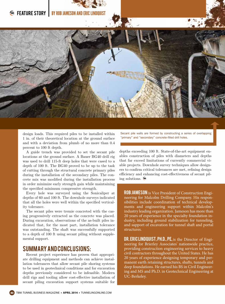
Secant Pile ConstructionSecant pile walls are formed by constructing a series
of overlapping “primary” and “secondary” concrete-filled drill holes. The primary piles are constructed first,
followed by secondary piles, which are cut into the pre-viously placed primary pile concrete. The amount of overlap required between the adjacent piles is a function of the structural design requirements and the installa-tion tolerance that can be achieved.
The success of a secant pile system requires that the in-dividual piles be structurally sound over their full length, and that adjacent piles be constructed to tolerances that maintain a reasonable overlap between the primary and secondary piles. Secant pile shafts can be constructed employing conventional lateral support methods, for ex-ample bracing or tiebacks, however the system is also efficient in ring compression structures. In this case, the piles are installed in a circular configuration and loads are efficiently resisted circumferential compression of un-reinforced concrete. Historically, excavation depths for which secant pile compression ring structures have been employed have typically been limited to around 60 ft, due to limitations on installation tolerances. Recent improve-ments in drilling equipment and methods, combined with instrumentation to verify actual installation tolerances, are allowing cost-effective use of secant piles for excava-tions extending beyond 100 ft.
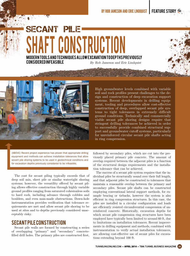
(ABOVE) Recent project experience has proven that appropriate drilling equipment and methods can achieve installation tolerances that allow secant pile shoring systems to be used in geotechnical conditions and for excavation depths previously considered to be infeasible.
High groundwater levels combined with variable soil and rock profiles present challenges to the de-sign and construction of deep excavation support systems. Recent developments in drilling equip-ment, tooling and procedures allow cost-effective construction of deep, overlapped secant pile sys-tems to tight tolerances in extremely difficult ground conditions. Technically and commercially viable secant pile shoring designs require that stringent drilling tolerances be achieved in order to successfully provide combined structural sup-port and groundwater cutoff systems, particularly for unreinforced circular secant pile shafts acting in ring compression.
tunnelingonline.com APRIL 2014 tBm: tunnel Business magazinetBm: tunnel Business magazine APRIL 2014 tunnelingonline.com36
feature story by Rob jameson and eRic lindquist
For secant piling, installation tolerance is critical to project success and directly related to cost. When tight tolerances are maintained, pile spacing is maximized, re-ducing the number of piles required along an excavation perimeter. Once the permissible tolerance is defined, the pile installer must select construction procedures and equipment to satisfy this controlling performance crite-rion, while minimizing unit construction costs, typically by maximizing production rates.
Tolerance is evaluated in terms of both layout control and drilling verticality. A guide trench or drilling tem-plate is used in order to ensure pile location is controlled at ground surface, typically to within +/-1 in. Vertical-ity tolerances of 0.5 percent (1 in 200) or stricter are typically necessary for secant piling projects. Pile spac-ing is maximized for economy, and therefore success-ful secant piling projects require exceptional attention to drilling procedures, equipment and quality control to ensure overlap is maintained. Drilling methods and equipment selection are integrally linked in the con-struction process.
A range of techniques, including augercast and axial soil mixing, can be employed to install secant piles, pro-vided plan layout is controlled and initial rig verticality is confirmed and verified. These high productivity sys-tems combine technical performance, fast installation
and low cost, and are suitable for excavations in soil and soft rock to depths of up to 45 ft. Pile diameters are limited to 24 to 36 in. for these installation methods, but potential installation rates are in the range of 500 to 1,000 lf per shift.
For deeper excavations, layout control and drilling tol-erance become increasingly critical. Increased pile diam-eter and improved verticality control can both increase the viable depth of a secant pile excavation support sys-tem. Diameters of 36 to 48 in. are typically employed for 50 to 100 ft deep shoring systems. However, due to increased unit costs associated with large diameter piles, the construction methods must aim to optimize verticality in order to minimize pile quantity and cor-responding overall project costs.
Sectional heavy wall drill casing, advanced concur-rently with the drill tool, performs the dual function of maintaining boring stability in cohesionless or un-stable ground and stiffening the drill string in order to limit deviation at depth. Kelly drilling methods allow a range of soil and rock tooling to be employed within
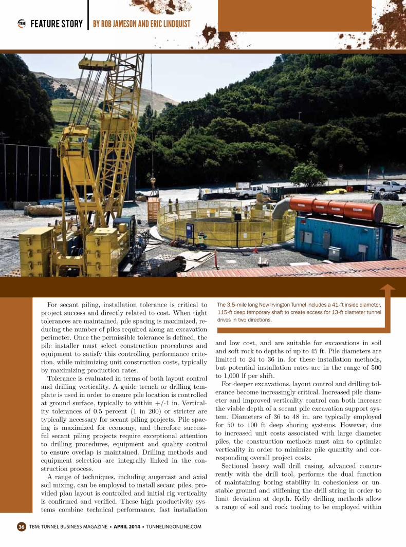
The 3.5-mile long New Irvington Tunnel includes a 41-ft inside diameter, 115-ft deep temporary shaft to create access for 13-ft diameter tunnel drives in two directions.

tunnelingonline.com APRIL 2014 tBm: tunnel Business magazine
tBm: tunnel Business magazine APRIL 2014 tunnelingonline.com38
feature story by Rob jameson and eRic lindquist
the casings such that different tools can be utilized to accommodate variations in ground type as the drill hole is advanced. Casing teeth configurations can be modi-fied between or even within project sites to suit actual ground conditions.
Top drive rotary crawler drills are ideally suited to secant piling and can rapidly advance drill tools concur-rent with the casing while maintaining strict verticality tolerances. Numerous commercially available rigs with torque in the range of 150 to 195 kip-ft are suitable for pile depths up to 60 ft. Greater pile depths require en-hanced equipment capabilities for efficient advance rates and handling of casing and drill tools. Machines with torque in the range of 260 to 295 kip-ft are usually em-ployed for drilling to depths of 100 ft. Production rates can be in the range of 150 to 300 lf per shift.
In parallel with the evaluation of rig torque, drill se-lection should consider the weight of casing that can be efficiently handled by the machine. For depths exceed-ing 100 ft, and diameters in the range of 42 in., either very large rigs, such as the Bauer BG50, or oscillator attachments are required to assist casing advance and extraction due to the self-weight of the drill string.
Secant Pile Verification:In the absence of downhole verticality measurements,
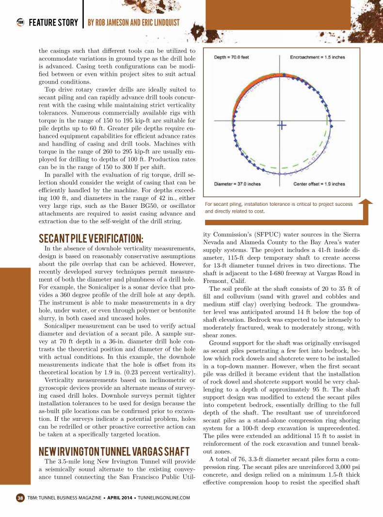
design is based on reasonably conservative assumptions about the pile overlap that can be achieved. However, recently developed survey techniques permit measure-ment of both the diameter and plumbness of a drill hole. For example, the Sonicaliper is a sonar device that pro-vides a 360 degree profile of the drill hole at any depth. The instrument is able to make measurements in a dry hole, under water, or even through polymer or bentonite slurry, in both cased and uncased holes.
Sonicaliper measurement can be used to verify actual diameter and deviation of a secant pile. A sample sur-vey at 70 ft depth in a 36-in. diameter drill hole con-trasts the theoretical position and diameter of the hole with actual conditions. In this example, the downhole measurements indicate that the hole is offset from its theoretical location by 1.9 in. (0.23 percent verticality).
Verticality measurements based on inclinometric or gyroscopic devices provide an alternate means of survey-ing cased drill holes. Downhole surveys permit tighter installation tolerances to be used for design because the as-built pile locations can be confirmed prior to excava-tion. If the surveys indicate a potential problem, holes can be redrilled or other proactive corrective action can be taken at a specifically targeted location.
New Irvington Tunnel Vargas ShaftThe 3.5-mile long New Irvington Tunnel will provide
a seismically sound alternate to the existing convey-ance tunnel connecting the San Francisco Public Util-
ity Commission’s (SFPUC) water sources in the Sierra Nevada and Alameda County to the Bay Area’s water supply systems. The project includes a 41-ft inside di-ameter, 115-ft deep temporary shaft to create access for 13-ft diameter tunnel drives in two directions. The shaft is adjacent to the I-680 freeway at Vargas Road in Fremont, Calif.
The soil profile at the shaft consists of 20 to 35 ft of fill and colluvium (sand with gravel and cobbles and medium stiff clay) overlying bedrock. The groundwa-ter level was anticipated around 14 ft below the top of shaft elevation. Bedrock was expected to be intensely to moderately fractured, weak to moderately strong, with shear zones.
Ground support for the shaft was originally envisaged as secant piles penetrating a few feet into bedrock, be-low which rock dowels and shotcrete were to be installed in a top-down manner. However, when the first secant pile was drilled it became evident that the installation of rock dowel and shotcrete support would be very chal-lenging to a depth of approximately 95 ft. The shaft support design was modified to extend the secant piles into competent bedrock, essentially drilling to the full depth of the shaft. The resultant use of unreinforced secant piles as a stand-alone compression ring shoring system for a 100-ft deep excavation is unprecedented. The piles were extended an additional 15 ft to assist in reinforcement of the rock excavation and tunnel break-out zones.
A total of 76, 3.3-ft diameter secant piles form a com-pression ring. The secant piles are unreinforced 3,000 psi concrete, and design relied on a minimum 1.5-ft thick effective compression hoop to resist the specified shaft
For secant piling, installation tolerance is critical to project success and directly related to cost.
tBm: tunnel Business magazine APRIL 2014 tunnelingonline.com40
feature story by Rob jameson and eRic lindquist
design loads. This required piles to be installed within 1 in. of their theoretical location at the ground surface and with a deviation from plumb of no more than 0.4 percent to 100 ft depth.
A guide trench was provided to set the secant pile locations at the ground surface. A Bauer BG40 drill rig was used to drill 115-ft deep holes that were cased to a depth of 100 ft. The BG40 proved to be up to the task of cutting through the structural concrete primary piles during the installation of the secondary piles. The con-crete mix was modified during the installation process in order minimize early strength gain while maintaining the specified minimum compressive strength.
Every hole was surveyed using the Sonicaliper at depths of 60 and 100 ft. The downhole surveys indicated that all the holes were well within the specified vertical-ity tolerance.
The secant piles were tremie concreted with the cas-ing progressively extracted as the concrete was placed. During excavation, observations of the as-built piles in-dicated that, for the most part, installation tolerance was outstanding. The shaft was successfully supported to a depth of 100 ft using secant piling without supple-mental support.
Summary and Conclusions:Recent project experience has proven that appropri-
ate drilling equipment and methods can achieve instal-lation tolerances that allow secant pile shoring systems to be used in geotechnical conditions and for excavation depths previously considered to be infeasible. Modern drill rigs and tooling allow cost-effective installation of secant piling excavation support systems suitable for
depths exceeding 100 ft. State-of-the-art equipment en-ables construction of piles with diameters and depths that far exceed limitations of currently commercial vi-able projects. Downhole survey techniques allow design-ers to confirm critical tolerances are met, refining design efficiency and enhancing cost-effectiveness of secant pil-ing solutions.
Rob Jameson is Vice President of Construction Engi-neering for Malcolm Drilling Company. His respon-sibilities include coordination of technical develop-ments and engineering support within Malcolm's industry leading organization. Jameson has more than 20 years of experience in the specialty foundation in-dustry, including ground stabilization for tunneling, and support of excavation for tunnel shaft and portal structures.
Dr. Eric Lindquist, Ph.D., PE, is the Director of Engi-neering for Brierley Associates' nationwide practice, providing construction engineering services to heavy civil contractors throughout the United States. He has 20 years of experience designing temporary and per-manent earth retaining structures, shafts, tunnels and deep foundations. He earned his BS in Civil Engineer-ing and MS and Ph.D. in Geotechnical Engineering at UC-Berkeley.
Secant pile walls are formed by constructing a series of overlapping “primary” and “secondary” concrete-filled drill holes.