Embed Size (px)
DESCRIPTION
sec2012nissan
Citation preview
BODY EXTERIOR, DOORS, ROOF & VEHICLE SECURITY
C
D
E
SECTION SECA
B
SECURITY CONTROL SYSTEM
F
G
H
I
J
L
M
EC
N
O
P
CONTENTS
S
BASIC INSPECTION .................................... 6
DIAGNOSIS AND REPAIR WORK FLOW ......... 6Work Flow .................................................................6
INSPECTION AND ADJUSTMENT ..................... 9
ECM RECOMMUNICATING FUNCTION ....................9ECM RECOMMUNICATING FUNCTION : De-scription .....................................................................9ECM RECOMMUNICATING FUNCTION : Special Repair Requirement ..................................................9
SYSTEM DESCRIPTION .............................10
INTELLIGENT KEY SYSTEM/ENGINE START FUNCTION ............................................10
System Diagram ......................................................10System Description .................................................10Component Parts Location ......................................14Component Description ...........................................15
NISSAN VEHICLE IMMOBILIZER SYSTEM-NATS ..................................................................17
System Diagram ......................................................17System Description .................................................17Component Parts Location ......................................19Component Description ..........................................20
VEHICLE SECURITY SYSTEM .........................22System Diagram ......................................................22System Description .................................................22Component Parts Location ......................................24Component Description ...........................................25
DIAGNOSIS SYSTEM (BCM) ............................26
COMMON ITEM .........................................................26COMMON ITEM : CONSULT-III Function (BCM - COMMON ITEM) .....................................................26
INTELLIGENT KEY ...................................................27
INTELLIGENT KEY : CONSULT-III Function (BCM - INTELLIGENT KEY) ....................................27
THEFT ALM ...............................................................31THEFT ALM : CONSULT-III Function (BCM - THEFT) ....................................................................31
IMMU ..........................................................................32IMMU : CONSULT-III Function (BCM - IMMU) ........32
DTC/CIRCUIT DIAGNOSIS .........................33
U1000 CAN COMM CIRCUIT ...........................33
BCM ...........................................................................33BCM : Description ....................................................33BCM : DTC Logic .....................................................33BCM : Diagnosis Procedure ....................................33
IPDM E/R ....................................................................33IPDM E/R : Description ............................................33IPDM E/R : DTC Logic .............................................33IPDM E/R : Diagnosis Procedure ............................33
U1010 CONTROL UNIT (CAN) .........................35
BCM ...........................................................................35BCM : DTC Logic .....................................................35BCM : Diagnosis Procedure ....................................35BCM : Special Repair Requirement .........................35
P1610 LOCK MODE .........................................36Description ...............................................................36DTC Logic ................................................................36Diagnosis Procedure ...............................................36
P1611 ID DISCORD, IMMU-ECM .....................37Description ...............................................................37DTC Logic ................................................................37Diagnosis Procedure ...............................................37
P1612 CHAIN OF ECM-IMMU ..........................39Description ...............................................................39
SEC-1Revision: 2010 October 2011 370Z
DTC Logic ............................................................... 39Diagnosis Procedure .............................................. 39
P1614 CHAIN OF IMMU-KEY ........................... 40Description .............................................................. 40DTC Logic ............................................................... 40Diagnosis Procedure .............................................. 40
P1615 DIFFRENCE OF KEY ............................. 43Description .............................................................. 43DTC Logic ............................................................... 43Diagnosis Procedure .............................................. 43
B2190 NATS ANTENNA AMP. ......................... 44Description .............................................................. 44DTC Logic ............................................................... 44Diagnosis Procedure .............................................. 44
B2191 DIFFERENCE OF KEY .......................... 47Description .............................................................. 47DTC Logic ............................................................... 47Diagnosis Procedure .............................................. 47
B2192 ID DISCORD, IMMU-ECM ...................... 48Description .............................................................. 48DTC Logic ............................................................... 48Diagnosis Procedure .............................................. 48
B2193 CHAIN OF ECM-IMMU ........................... 50Description .............................................................. 50DTC Logic ............................................................... 50Diagnosis Procedure .............................................. 50
B2195 ANTI-SCANNING ................................... 51Description .............................................................. 51DTC Logic ............................................................... 51Diagnosis Procedure .............................................. 51
B2013 ID DISCORD, IMMU-STRG .................... 52Description .............................................................. 52DTC Logic ............................................................... 52Diagnosis Procedure .............................................. 52
B2014 CHAIN OF STRG-IMMU ......................... 53Description .............................................................. 53DTC Logic ............................................................... 53Diagnosis Procedure .............................................. 53
B2555 STOP LAMP ........................................... 56Description .............................................................. 56DTC Logic ............................................................... 56Diagnosis Procedure .............................................. 56Component Inspection ............................................ 57
B2556 PUSH-BUTTON IGNITION SWITCH ..... 58Description .............................................................. 58DTC Logic ............................................................... 58Diagnosis Procedure .............................................. 58Component Inspection ............................................ 59
B2557 VEHICLE SPEED ................................... 60Description .............................................................. 60
DTC Logic ............................................................... 60Diagnosis Procedure ............................................... 60
B2560 STARTER CONTROL RELAY ............... 61Description .............................................................. 61DTC Logic ............................................................... 61Diagnosis Procedure ............................................... 61
B2601 SHIFT POSITION ................................... 62Description .............................................................. 62DTC Logic ............................................................... 62Diagnosis Procedure ............................................... 62Component Inspection ............................................ 64
B2602 SHIFT POSITION ................................... 65Description .............................................................. 65DTC Logic ............................................................... 65Diagnosis Procedure ............................................... 65Component Inspection ............................................ 66
B2603 SHIFT POSITION STATUS .................... 68Description .............................................................. 68DTC Logic ............................................................... 68Diagnosis Procedure ............................................... 68
B2604 PNP SWITCH ......................................... 71Description .............................................................. 71DTC Logic ............................................................... 71Diagnosis Procedure ............................................... 71
B2605 PNP SWITCH ......................................... 73Description .............................................................. 73DTC Logic ............................................................... 73Diagnosis Procedure ............................................... 73
B2606 STEERING LOCK RELAY ..................... 75Description .............................................................. 75DTC Logic ............................................................... 75Diagnosis Procedure ............................................... 75
B2607 STEERING LOCK RELAY ..................... 76Description .............................................................. 76DTC Logic ............................................................... 76Diagnosis Procedure ............................................... 76
B2608 STARTER RELAY ................................. 78Description .............................................................. 78DTC Logic ............................................................... 78Diagnosis Procedure ............................................... 78
B2609 STEERING STATUS .............................. 80Description .............................................................. 80DTC Logic ............................................................... 80Diagnosis Procedure ............................................... 80
B260B STEERING LOCK UNIT ........................ 84Description .............................................................. 84DTC Logic ............................................................... 84Diagnosis Procedure ............................................... 84
B260C STEERING LOCK UNIT ........................ 85Description .............................................................. 85
SEC-2Revision: 2010 October 2011 370Z
C
D
E
F
G
H
I
J
L
M
A
B
EC
N
O
P
S
DTC Logic ...............................................................85Diagnosis Procedure ...............................................85
B260D STEERING LOCK UNIT .........................86Description ..............................................................86DTC Logic ...............................................................86Diagnosis Procedure ...............................................86
B260F ENGINE STATUS ...................................87Description ..............................................................87DTC Logic ...............................................................87Diagnosis Procedure ...............................................87
B26E8 CLUTCH INTERLOCK SWITCH ............88Description ..............................................................88DTC Logic ...............................................................88Diagnosis Procedure ...............................................88Component Inspection ............................................89
B26E9 STEERING STATUS ..............................90Description ..............................................................90DTC Logic ...............................................................90Diagnosis Procedure ...............................................90
B26EA KEY REGISTRATION ............................91Description ..............................................................91DTC Logic ...............................................................91Diagnosis Procedure ...............................................91
B2612 STEERING STATUS ...............................92Description ..............................................................92DTC Logic ...............................................................92Diagnosis Procedure ...............................................92
B2617 STARTER RELAY CIRCUIT ...................96Description ..............................................................96DTC Logic ...............................................................96Diagnosis Procedure ...............................................96
B2619 BCM ........................................................98Description ..............................................................98DTC Logic ...............................................................98Diagnosis Procedure ...............................................98
B261E VEHICLE TYPE ......................................99Description ..............................................................99DTC Logic ...............................................................99Diagnosis Procedure ...............................................99
B261F ASCD CLUTCH SWITCH ..................... 100Description ............................................................ 100DTC Logic ............................................................. 100Diagnosis Procedure ............................................. 100Component Inspection .......................................... 101
B2108 STEERING LOCK RELAY .................... 102Description ............................................................ 102DTC Logic ............................................................. 102Diagnosis Procedure ............................................. 102
B2109 STEERING LOCK RELAY .................... 104Description ............................................................ 104
DTC Logic ..............................................................104Diagnosis Procedure .............................................104
B210A STEERING LOCK CONDITION SWITCH ........................................................... 105
Description .............................................................105DTC Logic ..............................................................105Diagnosis Procedure .............................................105
B210B STARTER CONTROL RELAY ............ 109Description .............................................................109DTC Logic ..............................................................109Diagnosis Procedure .............................................109
B210C STARTER CONTROL RELAY ............ 110Description .............................................................110DTC Logic ..............................................................110Diagnosis Procedure .............................................110
B210D STARTER RELAY .............................. 111Description .............................................................111DTC Logic ..............................................................111Diagnosis Procedure .............................................111
B210E STARTER RELAY ............................... 112Description .............................................................112DTC Logic ..............................................................112Diagnosis Procedure .............................................112
B210F PNP/CLUTCH INTERLOCK SWITCH . 114Description .............................................................114DTC Logic ..............................................................114Diagnosis Procedure .............................................114
B2110 PNP/CLUTCH INTERLOCK SWITCH . 116Description .............................................................116DTC Logic ..............................................................116Diagnosis Procedure .............................................116
POWER SUPPLY AND GROUND CIRCUIT .. 118
BCM .........................................................................118BCM : Diagnosis Procedure ..................................118
IPDM E/R ..................................................................118IPDM E/R : Diagnosis Procedure ..........................118
KEY SLOT ....................................................... 120Description .............................................................120Component Function Check ................................120Diagnosis Procedure .............................................120
KEY SLOT INDICATOR .................................. 121Description .............................................................121Component Function Check ................................121Diagnosis Procedure .............................................121
HOOD SWITCH ............................................... 123Description .............................................................123Component Function Check ................................123Diagnosis Procedure ............................................123Component Inspection ...........................................124
SEC-3Revision: 2010 October 2011 370Z
HORN FUNCTION ........................................... 125Description .............................................................125Component Function Check ................................125Diagnosis Procedure ............................................125
SECURITY INDICATOR LAMP ....................... 127Description .............................................................127Component Function Check ................................127Diagnosis Procedure .............................................127
KEY WARNING LAMP .................................... 129Description .............................................................129Component Function Check ................................129Diagnosis Procedure .............................................129
INTELLIGENT KEY SYSTEM/ENGINE START FUNCTION .......................................... 130
Wiring Diagram - INTELLIGENT KEY SYSTEM/ENGINE START FUNCTION - ..............................130
NISSAN VEHICLE IMMOBILIZER SYSTEM-NATS ................................................................ 143
Wiring Diagram - NISSAN VEHICLE IMMOBILIZ-ER SYSTEM - ........................................................143
VEHICLE SECURITY SYSTEM ....................... 152Wiring Diagram - VEHICLE SECURITY SYSTEM - .............................................................................152
ECU DIAGNOSIS INFORMATION .............162
BCM ................................................................. 162Reference Value ....................................................162Wiring Diagram - BCM - ........................................187Fail-safe .................................................................193DTC Inspection Priority Chart .............................195DTC Index .............................................................196
IPDM E/R ......................................................... 199Reference Value ....................................................199Wiring Diagram - IPDM E/R - .................................206Fail-safe .................................................................209DTC Index .............................................................211
SYMPTOM DIAGNOSIS ............................212
ENGINE DOES NOT START WHEN INTELLI-GENT KEY IS INSIDE OF VEHICLE ............... 212
Description .............................................................212Diagnosis Procedure .............................................212
STEERING DOES NOT LOCK ........................ 213Description .............................................................213Diagnosis Procedure .............................................213
SECURITY INDICATOR LAMP DOES NOT TURN ON OR BLINK ....................................... 214
Description .............................................................214Diagnosis Procedure .............................................214
VEHICLE SECURITY SYSTEM CANNOT BE SET ...................................................................215
INTELLIGENT KEY ................................................. 215INTELLIGENT KEY : Description .......................... 215INTELLIGENT KEY : Diagnosis Procedure .......... 215
DOOR REQUEST SWITCH ..................................... 215DOOR REQUEST SWITCH : Description ............. 215DOOR REQUEST SWITCH : Diagnosis Proce-dure ....................................................................... 215
VEHICLE SECURITY ALARM DOES NOT ACTIVATE ........................................................217
Description ............................................................ 217Diagnosis Procedure ............................................. 217
INTELLIGENT KEY INSERT INFORMATION DOES NOT OPERATE .....................................218
Description ............................................................ 218Diagnosis Procedure ............................................. 218
PANIC ALARM FUNCTION DOES NOT OP-ERATE ..............................................................220
Description ............................................................ 220Diagnosis Procedure ............................................. 220
PRECAUTION ...........................................221
PRECAUTIONS ................................................221
FOR USA AND CANADA ....................................... 221FOR USA AND CANADA : Precaution for Supple-mental Restraint System (SRS) "AIR BAG" and "SEAT BELT PRE-TENSIONER" ......................... 221FOR USA AND CANADA : Precaution Necessary for Steering Wheel Rotation after Battery Discon-nect ....................................................................... 221FOR USA AND CANADA : Precaution for Battery Service .................................................................. 222FOR USA AND CANADA : Precaution for Proce-dure without Cowl Top Cover ................................ 222
FOR MEXICO .......................................................... 222FOR MEXICO : Precaution for Supplemental Re-straint System (SRS) "AIR BAG" and "SEAT BELT PRE-TENSIONER" ............................................... 222FOR MEXICO : Precaution Necessary for Steer-ing Wheel Rotation after Battery Disconnect ........ 222FOR MEXICO : Precaution for Battery Service .... 223FOR MEXICO : Precaution for Procedure without Cowl Top Cover .................................................... 223
REMOVAL AND INSTALLATION .............224
KEY SLOT ........................................................224Exploded View ...................................................... 224Removal and Installation ....................................... 224
PUSH BUTTON IGNITION SWITCH ................225Exploded View ...................................................... 225
SEC-4Revision: 2010 October 2011 370Z
C
D
E
F
G
H
I
J
L
M
A
B
EC
N
O
P
S
Removal and Installation ....................................... 225
SEC-5Revision: 2010 October 2011 370Z
DIAGNOSIS AND REPAIR WORK FLOW
< BASIC INSPECTION >BASIC INSPECTIONDIAGNOSIS AND REPAIR WORK FLOW
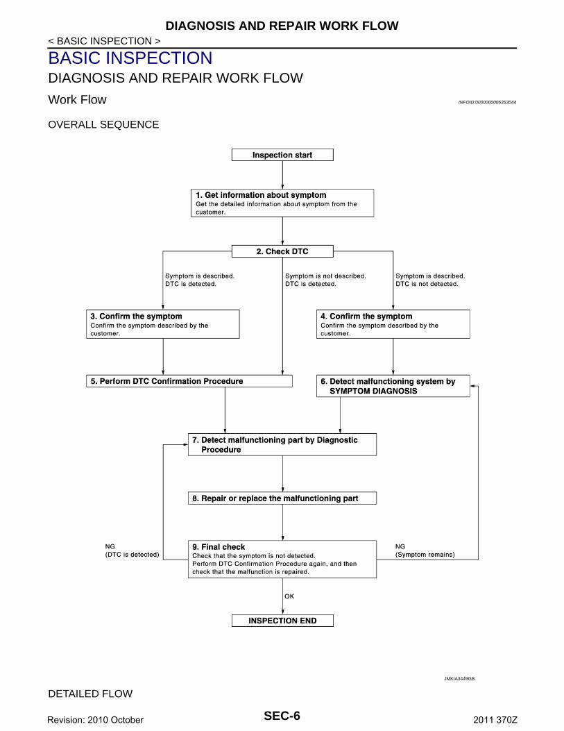
Work Flow INFOID:0000000006353044
OVERALL SEQUENCE
DETAILED FLOW
JMKIA3449GB
SEC-6Revision: 2010 October 2011 370Z
DIAGNOSIS AND REPAIR WORK FLOW
C
D
E
F
G
H
I
J
L
M
A
B
EC
N
O
P
< BASIC INSPECTION >
S
1.GET INFORMATION ABOUT SYMPTOM
Get detailed information from the customer about the symptom (the condition and the environment when theincident/malfunction occurs).
>> GO TO 2.
2.CHECK DTC
1. Check DTC of BCM and IPDM E/R.2. Perform the following procedure if DTC is detected.- Record DTC and freeze frame data (Print them out using CONSULT-III.)- Erase DTC.- Study the relationship between the cause detected by DTC and the symptom described by the customer.3. Check related service bulletins for information.Are any symptoms described and any DTC detected?Symptom is described, DTC is detected>>GO TO 3.Symptom is described, DTC is not detected>>GO TO 4.Symptom is not described, DTC is detected>>GO TO 5.
3.CONFIRM THE SYMPTOM
Confirm the symptom described by the customer.Connect CONSULT-III to the vehicle and check self-diagnostic results in real time.Verify relation between the symptom and the condition when the symptom is detected.
>> GO TO 5.
4.CONFIRM THE SYMPTOM
Confirm the symptom described by the customer.Connect CONSULT-III to the vehicle and check self-diagnostic results in real time.Verify relation between the symptom and the condition when the symptom is detected.
>> GO TO 6.
5.PERFORM DTC CONFIRMATION PROCEDURE
Perform DTC Confirmation Procedure for the detected DTC, and then check that DTC is detected again.At this time, always connect CONSULT-III to the vehicle and check self-diagnostic results in real time.If two or more DTCs are detected, refer to SEC-195, "DTC Inspection Priority Chart" (BCM) or SEC-211,"DTC Index" (IPDM E/R), and determine trouble diagnosis order.Is DTC detected?YES >> GO TO 7.NO >> Refer to GI-42, "Intermittent Incident".
6.DETECT MALFUNCTIONING SYSTEM BY SYMPTOM DIAGNOSIS
Detect malfunctioning system according to SYMPTOM DIAGNOSIS based on the confirmed symptom in step4, and determine the trouble diagnosis order based on possible causes and symptom.
>> GO TO 7.
7.DETECT MALFUNCTIONING PART BY DIAGNOSTIC PROCEDURE
Inspect according to Diagnostic Procedure of the system.NOTE:The Diagnostic Procedure is described based on open and short circuit inspection. Is malfunctioning part detected?YES >> GO TO 8.NO >> Check voltage of related BCM terminals using CONSULT-III.
8.REPAIR OR REPLACE THE MALFUNCTIONING PART
1. Repair or replace the malfunctioning part.
SEC-7Revision: 2010 October 2011 370Z
DIAGNOSIS AND REPAIR WORK FLOW
< BASIC INSPECTION >2. Reconnect parts or connectors disconnected during Diagnostic Procedure again after repair and replace-ment.3. Check DTC. If DTC is detected, erase it.
>> GO TO 9.
9.FINAL CHECK
When DTC is detected in step 2, perform DTC Confirmation Procedure or Component Function Check again,and then check that the malfunction is repaired securely.When symptom is described by the customer, refer to confirmed symptom in step 3 or 4, and check that thesymptom is not detected.Does the symptom reappear?YES (DTC is detected)>>GO TO 7.YES (Symptom remains)>>GO TO 6.NO >> INSPECTION END
SEC-8Revision: 2010 October 2011 370Z
INSPECTION AND ADJUSTMENT
C
D
E
F
G
H
I
J
L
M
A
B
EC
N
O
P
< BASIC INSPECTION >
S
INSPECTION AND ADJUSTMENTECM RECOMMUNICATING FUNCTION
ECM RECOMMUNICATING FUNCTION : Description INFOID:0000000006353045
Performing the following procedure can automatically activate recommunication of ECM and BCM, but onlywhen the ECM is replaced with a new one*.*: New one means a virgin ECM that is never energized on-board.(In this step, initialization procedure by CONSULT-III is not necessary)NOTE:• When registering new Key IDs or replacing the ECM that is not brand new, refer to CONSULT-III Oper-
ation Manual NATS-IVIS/NVIS.• If multiple keys are attached to the key holder, separate them before beginning work.• Distinguish keys with unregistered key IDs from those with registered IDs.
ECM RECOMMUNICATING FUNCTION : Special Repair Requirement INFOID:0000000006353046
1.PERFORM ECM RECOMMUNICATING FUNCTION
1. Install ECM.2. Insert the registered Intelligent Key* into key slot, turn ignition switch to “ON”.
*: To perform this step, use the key that is used before performing ECM replacement.3. Maintain ignition switch in the “ON” position for 5 seconds or more.4. Turn ignition switch to “OFF”.5. Start engine.Can engine be started?YES >> Procedure is complete.NO >> Initialize control unit. Refer to CONSULT-III Operation Manual NATS-IVIS/NVIS.
SEC-9Revision: 2010 October 2011 370Z
INTELLIGENT KEY SYSTEM/ENGINE START FUNCTION
< SYSTEM DESCRIPTION >SYSTEM DESCRIPTIONINTELLIGENT KEY SYSTEM/ENGINE START FUNCTION
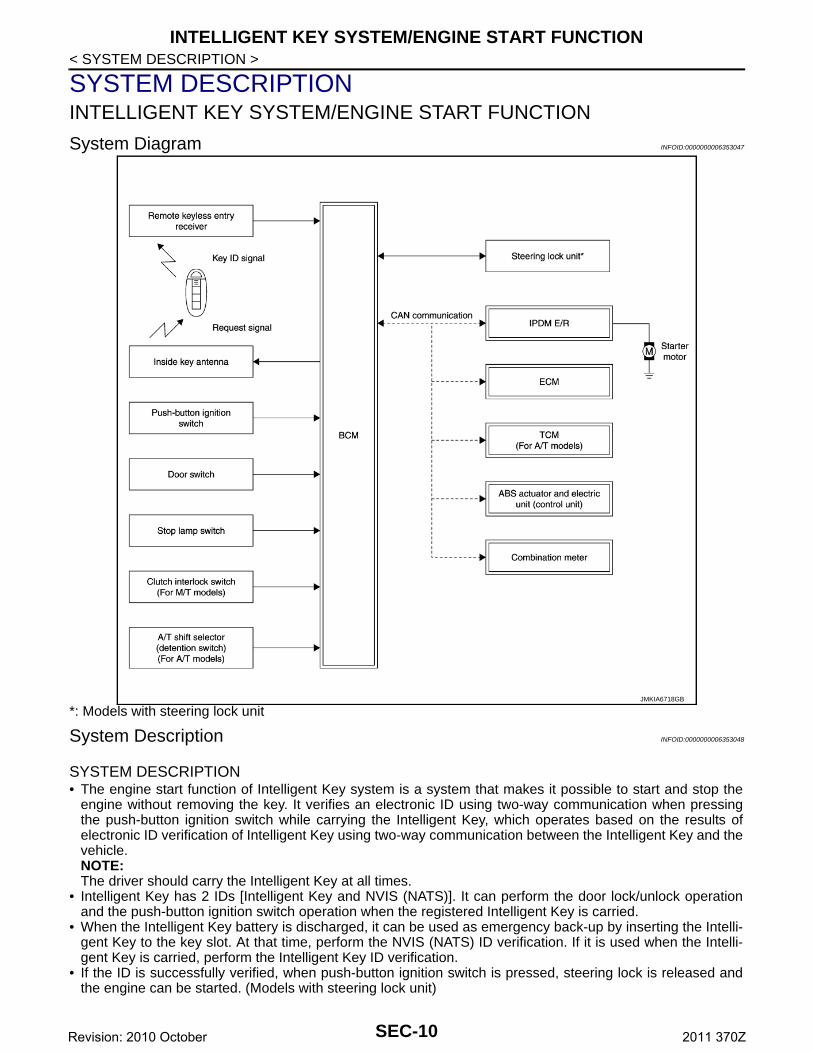
System Diagram INFOID:0000000006353047
*: Models with steering lock unit
System Description INFOID:0000000006353048
SYSTEM DESCRIPTION • The engine start function of Intelligent Key system is a system that makes it possible to start and stop the
engine without removing the key. It verifies an electronic ID using two-way communication when pressingthe push-button ignition switch while carrying the Intelligent Key, which operates based on the results ofelectronic ID verification of Intelligent Key using two-way communication between the Intelligent Key and thevehicle.NOTE:The driver should carry the Intelligent Key at all times.
• Intelligent Key has 2 IDs [Intelligent Key and NVIS (NATS)]. It can perform the door lock/unlock operationand the push-button ignition switch operation when the registered Intelligent Key is carried.
• When the Intelligent Key battery is discharged, it can be used as emergency back-up by inserting the Intelli-gent Key to the key slot. At that time, perform the NVIS (NATS) ID verification. If it is used when the Intelli-gent Key is carried, perform the Intelligent Key ID verification.
• If the ID is successfully verified, when push-button ignition switch is pressed, steering lock is released andthe engine can be started. (Models with steering lock unit)
JMKIA6718GB
SEC-10Revision: 2010 October 2011 370Z
INTELLIGENT KEY SYSTEM/ENGINE START FUNCTION
C
D
E
F
G
H
I
J
L
M
A
B
EC
N
O
P
< SYSTEM DESCRIPTION >
S
• Up to 4 Intelligent Keys can be registered (Including the standard Intelligent Key) upon request from the cus-tomer.NOTE:Refer to DLK-24, "INTELLIGENT KEY SYSTEM : System Description" for any functions other than enginestart function of Intelligent Key system.
PRECAUTIONS FOR INTELLIGENT KEY SYSTEMIn the Intelligent Key system, the transponder [the chip for NVIS (NATS) ID verification] is integratedinto the Intelligent Key. (For the conventional models, it is integrated into the mechanical key.) There-fore, the mechanical key cannot perform ID verification, and thus it cannot start the engine. Instead,NVIS (NATS) ID verification can be performed by inserting the Intelligent Key to the key slot, and thenit can start the engine.
OPERATION WHEN INTELLIGENT KEY IS CARRIED
Models with steering lock unit
1. When the push-button ignition switch is pressed, the BCM activates the inside key antenna and transmitsthe request signal to the Intelligent Key.
2. The Intelligent Key receives the request signal and transmits the Intelligent Key ID signal to the BCM.3. The BCM receives the Intelligent Key ID signal via the remote keyless entry receiver, and verifies it with
the registered ID.4. BCM transmits the steering unlock signal to steering lock unit and IPDM E/R, if the verification results are
OK.5. IPDM E/R turns the steering lock relay ON to supply power source to the steering lock unit.6. The steering lock releases.7. BCM transmits the power supply stop signal to IPDM E/R when detecting that the steering lock is in the
unlock condition.8. IPDM E/R turns the steering lock relay OFF to stop power supply to the steering lock unit.9. BCM turns ACC relay ON and transmits the ignition power supply ON signal to IPDM E/R.10. IPDM E/R turns the ignition relay ON to start the ignition power supply.11. BCM detects that the selector lever position and brake pedal operating condition (A/T models), or shift
lever position and clutch pedal operation condition (M/T models).12. BCM transmits the starter request signal via CAN communication to IPDM E/R and turns the starter relay
in IPDM E/R ON if BCM judges that the engine start condition is satisfied.13. IPDM E/R turns the starter control relay ON when receiving the starter request signal.14. Battery power is supplied through the starter relay and the starter control relay to operate the starter motor
to start the cranking.CAUTION:If a malfunction is detected in the Intelligent Key system, the “KEY” warning lamp in the combina-tion meter illuminates. At that time, the engine cannot be started.
15. When BCM receives feedback signal from ECM indicating that the engine is started, the BCM transmits astop signal to IPDM E/R and stops cranking by turning OFF the starter motor relay. (If engine start isunsuccessful, cranking stops automatically within 5 seconds.)CAUTION:When the Intelligent Key is carried outside of the vehicle (inside key antenna detection area) whilethe power supply is in the ACC or ON position, even if the engine start condition* is satisfied, theengine cannot be started.
*: For the engine start condition, refer to “POWER SUPPLY POSITION CHANGE TABLE BY PUSH-BUTTONIGNITION SWITCH OPERATION”.
Models without steering lock unit
1. When the push-button ignition switch is pressed, the BCM activates the inside key antenna and transmitsthe request signal to the Intelligent Key.
2. The Intelligent Key receives the request signal and transmits the Intelligent Key ID signal to the BCM.3. The BCM receives the Intelligent Key ID signal via the remote keyless entry receiver, and verifies it with
the registered ID.4. BCM turns ACC relay ON and transmits the ignition power supply ON signal to IPDM E/R.
SEC-11Revision: 2010 October 2011 370Z
INTELLIGENT KEY SYSTEM/ENGINE START FUNCTION
< SYSTEM DESCRIPTION >5. IPDM E/R turns the ignition relay ON to start the ignition power supply.6. BCM confirms that the shift position is P or N.7. BCM transmits the starter request signal via CAN communication to IPDM E/R and turns the starter relayin IPDM E/R ON if BCM judges that the engine start condition is satisfied.8. IPDM E/R turns the starter control relay ON when receiving the starter request signal.9. Battery power is supplied through the starter relay and the starter control relay to operate the starter motor
to start the cranking.CAUTION:If a malfunction is detected in the Intelligent Key system, the “KEY” warning lamp in the combina-tion meter illuminates. At that time, the engine cannot be started.
10. When BCM received feedback signal from ECM indicating that the engine is started, the BCM transmits astop signal to IPDM E/R and stops the cranking by turning OFF the starter motor relay. (If the engine initi-ating has failed, the cranking will stop automatically within 5 seconds.)CAUTION:When the Intelligent Key is carried outside of the vehicle (inside key antenna detection area) withthe power supply in ACC or ON position, even if the engine start condition* is satisfied, the enginecannot be started.
*: For the engine start condition, refer to “POWER SUPPLY POSITION CHANGE TABLE BY PUSH-BUTTONIGNITION SWITCH OPERATION”.
OPERATION RANGEEngine can be started when Intelligent Key is inside the vehicle. However, sometimes engine may not startwhen Intelligent Key is on instrument panel or in glove box.
OPERATION WHEN KEY SLOT IS USEDWhen the Intelligent Key battery is discharged, it performs NVIS (NATS) ID verification between the integratedtransponder and BCM by inserting the Intelligent Key into the key slot, and then the engine can be started.For details relating to starting the engine using key slot, refer to SEC-17, "System Description".
BATTERY SAVER SYSTEMWhen all the following conditions are met for 60 minutes, the battery saver system cuts off the power supply toprevent battery discharge.• The ignition switch is in the ACC position• All doors are closed• Selector lever is in the P position
Reset Condition of Battery Saver SystemA/T modelsIn order to prevent the battery from discharging, the battery saver system cuts off the power supply when alldoors are closed, the selector lever is in the P position, and the ignition switch is left in the ACC position for 60minutes. If any of the following conditions are met the battery saver system is released. At the same time, thesteering changes automatically to the lock position from the OFF position (models with steering lock unit).• Opening any door• Operating door lock using door request switch• Operating door lock using Intelligent KeyPress push-button ignition switch and ignition switch changes to the ACC position from the OFF position.M/T modelsIf any of the above conditions are met, the battery saver system is released.However, the steering is not locked (models with steering lock unit). In this case, the steering operation OFF toLOCK is prohibited.
STEERING LOCK OPERATION (MODELS WITH STEERING LOCK UNIT)Steering is locked by steering lock unit when ignition switch is in the OFF position, selector lever is in the Pposition, and any of the following conditions are met.• Opening door• Closing door• Door is locked using door request switch• Door is locked using Intelligent KeyNOTE:For models without steering lock unit, power supply position changes to LOCK even though the steering lockoperation is not performed.
SEC-12Revision: 2010 October 2011 370Z
INTELLIGENT KEY SYSTEM/ENGINE START FUNCTION
C
D
E
F
G
H
I
J
L
M
A
B
EC
N
O
P
< SYSTEM DESCRIPTION >
S
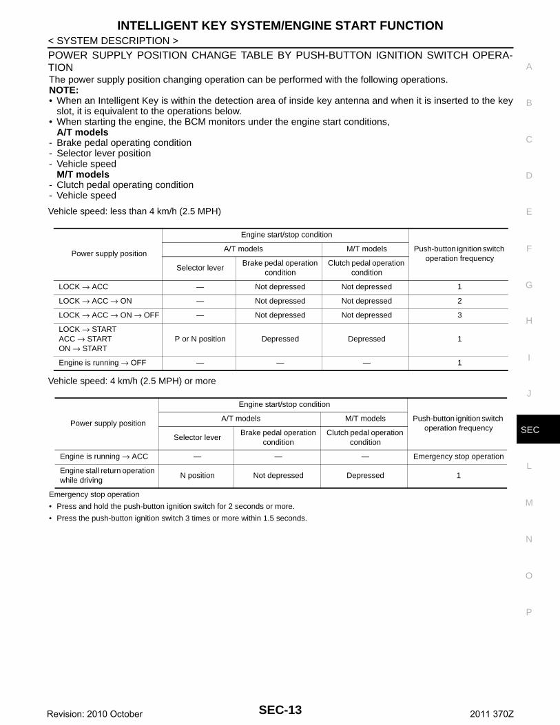
POWER SUPPLY POSITION CHANGE TABLE BY PUSH-BUTTON IGNITION SWITCH OPERA-TIONThe power supply position changing operation can be performed with the following operations.NOTE:• When an Intelligent Key is within the detection area of inside key antenna and when it is inserted to the key
slot, it is equivalent to the operations below.• When starting the engine, the BCM monitors under the engine start conditions,
A/T models- Brake pedal operating condition- Selector lever position- Vehicle speed
M/T models- Clutch pedal operating condition- Vehicle speed
Vehicle speed: less than 4 km/h (2.5 MPH)
Vehicle speed: 4 km/h (2.5 MPH) or more
Emergency stop operation
• Press and hold the push-button ignition switch for 2 seconds or more.
• Press the push-button ignition switch 3 times or more within 1.5 seconds.
Power supply position
Engine start/stop condition
Push-button ignition switch operation frequency
A/T models M/T models
Selector leverBrake pedal operation
conditionClutch pedal operation
condition
LOCK → ACC — Not depressed Not depressed 1
LOCK → ACC → ON — Not depressed Not depressed 2
LOCK → ACC → ON → OFF — Not depressed Not depressed 3
LOCK → STARTACC → STARTON → START
P or N position Depressed Depressed 1
Engine is running → OFF — — — 1
Power supply position
Engine start/stop condition
Push-button ignition switch operation frequency
A/T models M/T models
Selector leverBrake pedal operation
conditionClutch pedal operation
condition
Engine is running → ACC — — — Emergency stop operation
Engine stall return operation while driving
N position Not depressed Depressed 1
SEC-13Revision: 2010 October 2011 370Z
INTELLIGENT KEY SYSTEM/ENGINE START FUNCTION
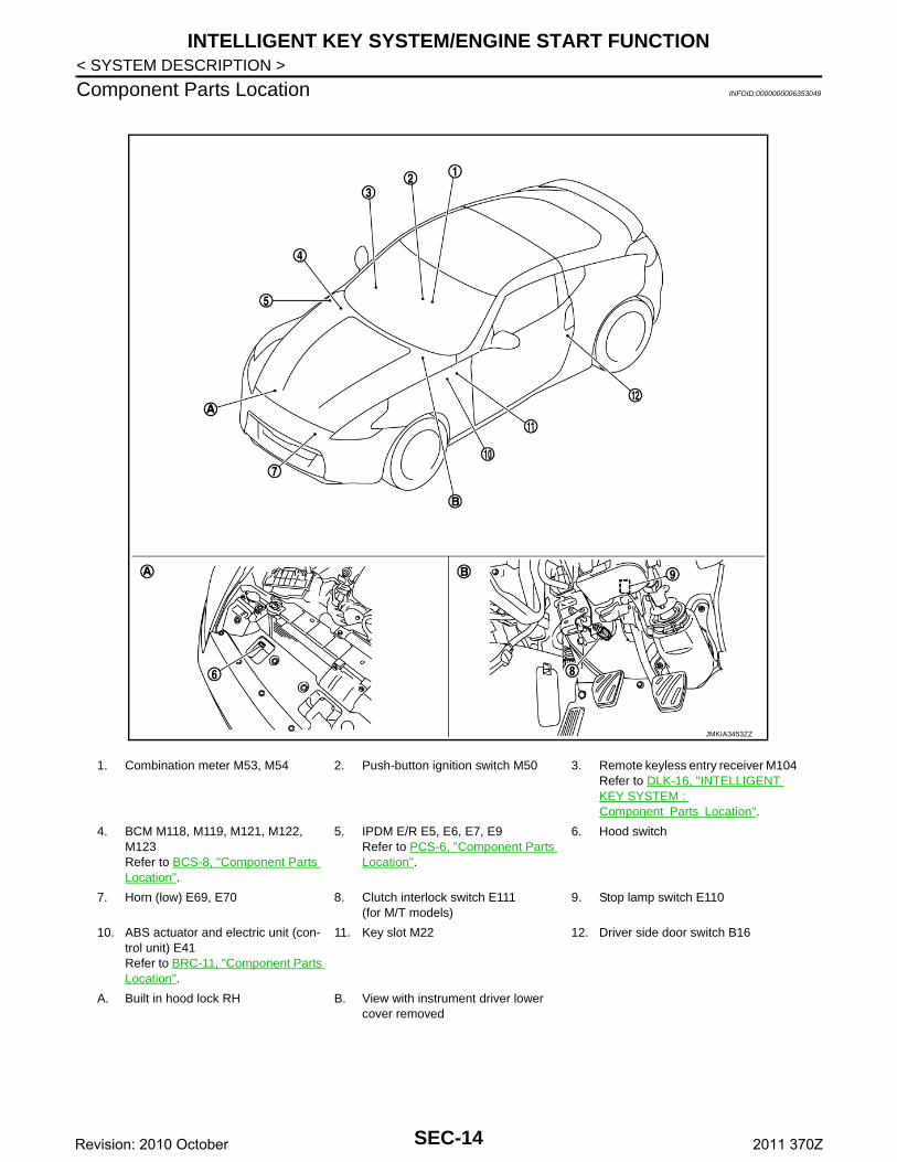
< SYSTEM DESCRIPTION >Component Parts Location INFOID:0000000006353049
1. Combination meter M53, M54 2. Push-button ignition switch M50 3. Remote keyless entry receiver M104 Refer to DLK-16, "INTELLIGENT KEY SYSTEM : Component Parts Location".
4. BCM M118, M119, M121, M122, M123Refer to BCS-8, "Component Parts Location".
5. IPDM E/R E5, E6, E7, E9Refer to PCS-6, "Component Parts Location".
6. Hood switch
7. Horn (low) E69, E70 8. Clutch interlock switch E111(for M/T models)
9. Stop lamp switch E110
10. ABS actuator and electric unit (con-trol unit) E41Refer to BRC-11, "Component Parts Location".
11. Key slot M22 12. Driver side door switch B16
A. Built in hood lock RH B. View with instrument driver lower cover removed
JMKIA3453ZZ
SEC-14Revision: 2010 October 2011 370Z
INTELLIGENT KEY SYSTEM/ENGINE START FUNCTION
C
D
E
F
G
H
I
J
L
M
A
B
EC
N
O
P
< SYSTEM DESCRIPTION >
S
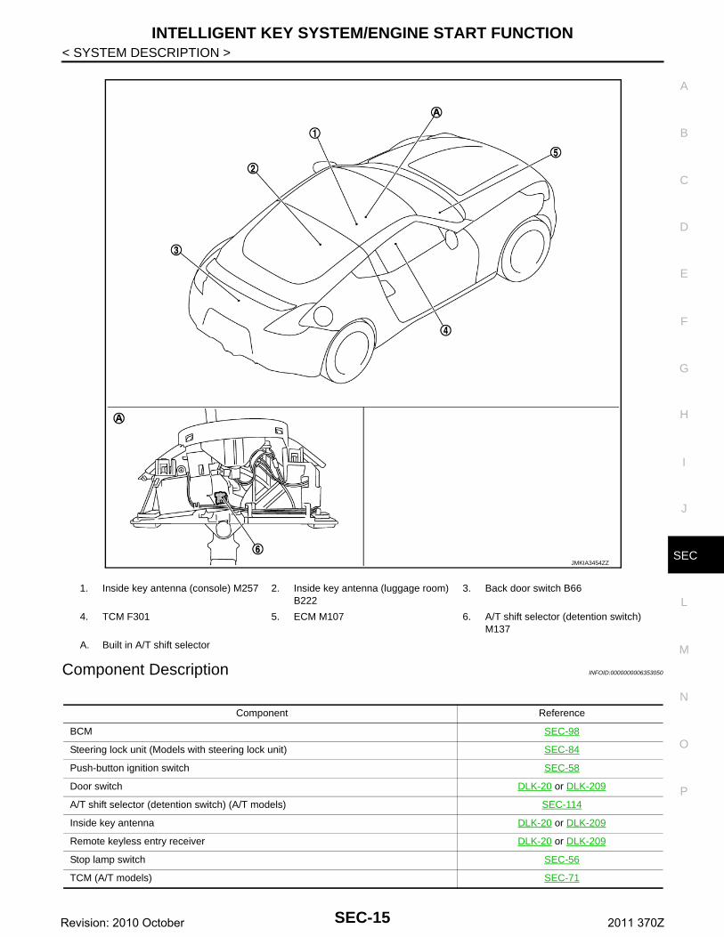
Component Description INFOID:0000000006353050
1. Inside key antenna (console) M257 2. Inside key antenna (luggage room) B222
3. Back door switch B66
4. TCM F301 5. ECM M107 6. A/T shift selector (detention switch) M137
A. Built in A/T shift selector
JMKIA3454ZZ
Component Reference
BCM SEC-98
Steering lock unit (Models with steering lock unit) SEC-84
Push-button ignition switch SEC-58
Door switch DLK-20 or DLK-209
A/T shift selector (detention switch) (A/T models) SEC-114
Inside key antenna DLK-20 or DLK-209
Remote keyless entry receiver DLK-20 or DLK-209
Stop lamp switch SEC-56
TCM (A/T models) SEC-71
SEC-15Revision: 2010 October 2011 370Z
INTELLIGENT KEY SYSTEM/ENGINE START FUNCTION
< SYSTEM DESCRIPTION >Clutch interlock switch (M/T models) SEC-88
Steering lock relay (Models with steering lock unit) SEC-75
Starter relay SEC-78
Starter control relay SEC-109
Security indicator lamp SEC-127
Key warning lamp SEC-129
Component Reference
SEC-16Revision: 2010 October 2011 370Z
NISSAN VEHICLE IMMOBILIZER SYSTEM-NATS
C
D
E
F
G
H
I
J
L
M
A
B
EC
N
O
P
< SYSTEM DESCRIPTION >
S
NISSAN VEHICLE IMMOBILIZER SYSTEM-NATS
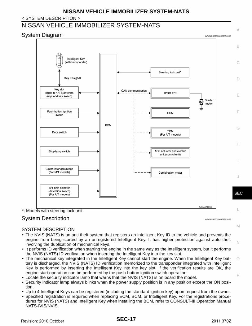
System Diagram INFOID:0000000006353051
*: Models with steering lock unit
System Description INFOID:0000000006353052
SYSTEM DESCRIPTION• The NVIS (NATS) is an anti-theft system that registers an Intelligent Key ID to the vehicle and prevents the
engine from being started by an unregistered Intelligent Key. It has higher protection against auto theftinvolving the duplication of mechanical keys.
• It performs ID verification when starting the engine in the same way as the Intelligent system, but it performsthe NVIS (NATS) ID verification when inserting the Intelligent Key into the key slot.
• The mechanical key integrated in the Intelligent Key cannot start the engine. When the Intelligent Key bat-tery is discharged, the NVIS (NATS) ID verification memorized to the transponder integrated with IntelligentKey is performed by inserting the Intelligent Key into the key slot. If the verification results are OK, theengine start operation can be performed by the push-button ignition switch operation.
• Locate the security indicator lamp that warns that the NVIS (NATS) is on board the model.• Security indicator lamp always blinks when the power supply position is in any position except the ON posi-
tion.• Up to 4 Intelligent Keys can be registered (including the standard ignition key) upon request from the owner.• Specified registration is required when replacing ECM, BCM, or Intelligent Key. For the registrations proce-
dures for NVIS (NATS) and Intelligent Key when installing the BCM, refer to CONSULT-III Operation ManualNATS-IVIS/NVIS.
JMKIA6719GB
SEC-17Revision: 2010 October 2011 370Z
NISSAN VEHICLE IMMOBILIZER SYSTEM-NATS
< SYSTEM DESCRIPTION >• Possible symptom of NVIS (NATS) malfunction is “Engine cannot start”. But the engine can not be startedwith other than NVIS (NATS) malfunction neither. Identify the possible causes according to “Work Flow”.Refer to SEC-6, "Work Flow".
• If ECM other than genuine part is installed, the engine cannot be started. For ECM replacement procedure,refer to EC-17, "ADDITIONAL SERVICE WHEN REPLACING CONTROL UNIT (ECM) : Special RepairRequirement".
PRECAUTIONS FOR KEY REGISTRATION• The key registration is a procedure that erases the current NVIS (NATS) ID once, and then reregisters a new
ID operation. Therefore a registered Intelligent Key is necessary for this procedure. Before starting the regis-tration operation collect all registered Intelligent Keys from the customer.
• When registering the Intelligent Key, perform only one procedure to simultaneously register both ID (NVIS“NATS” ID and Intelligent Key ID).The NVIS (NATS) ID registration is the procedure that registers the ID stored into the transponder (inte-grated in Intelligent Key) to BCM.The Intelligent key ID registration is the procedure that registers the ID to BCM.
• When performing the Intelligent Key system registration only, the engine cannot be started by inserting theIntelligent Key into the key slot. When performing the NVIS (NATS) registration only, the engine cannot bestarted by the operation when carrying the Intelligent Key. The registrations of both systems should be per-formed.
SECURITY INDICATOR LAMP• Warns that the vehicle is equipped with NVIS (NATS).• Security indicator lamp always blinks when the ignition switch is in any position except the ON position.NOTE:Because security indicator lamp is highly efficient, the battery is barely affected.
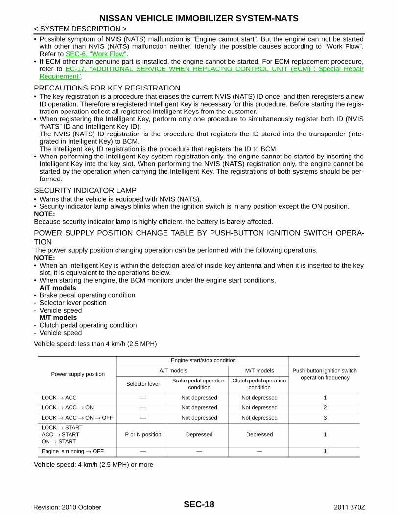
POWER SUPPLY POSITION CHANGE TABLE BY PUSH-BUTTON IGNITION SWITCH OPERA-TIONThe power supply position changing operation can be performed with the following operations.NOTE:• When an Intelligent Key is within the detection area of inside key antenna and when it is inserted to the key
slot, it is equivalent to the operations below.• When starting the engine, the BCM monitors under the engine start conditions,
A/T models- Brake pedal operating condition- Selector lever position- Vehicle speed
M/T models- Clutch pedal operating condition- Vehicle speed
Vehicle speed: less than 4 km/h (2.5 MPH)
Vehicle speed: 4 km/h (2.5 MPH) or more
Power supply position
Engine start/stop condition
Push-button ignition switch operation frequency
A/T models M/T models
Selector leverBrake pedal operation
conditionClutch pedal operation
condition
LOCK → ACC — Not depressed Not depressed 1
LOCK → ACC → ON — Not depressed Not depressed 2
LOCK → ACC → ON → OFF — Not depressed Not depressed 3
LOCK → STARTACC → STARTON → START
P or N position Depressed Depressed 1
Engine is running → OFF — — — 1
SEC-18Revision: 2010 October 2011 370Z
NISSAN VEHICLE IMMOBILIZER SYSTEM-NATS
C
D
E
F
G
H
I
J
L
M
A
B
EC
N
O
P
< SYSTEM DESCRIPTION >
S
Emergency stop operation
• Press and hold the push-button ignition switch for 2 seconds or more.
• Press the push-button ignition switch 3 times or more within 1.5 seconds.
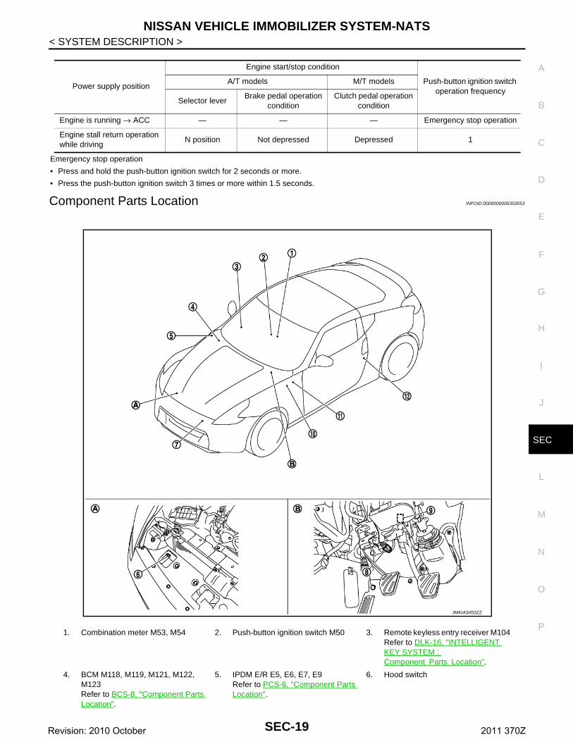
Component Parts Location INFOID:0000000006353053
Power supply position
Engine start/stop condition
Push-button ignition switch operation frequency
A/T models M/T models
Selector leverBrake pedal operation
conditionClutch pedal operation
condition
Engine is running → ACC — — — Emergency stop operation
Engine stall return operation while driving
N position Not depressed Depressed 1
1. Combination meter M53, M54 2. Push-button ignition switch M50 3. Remote keyless entry receiver M104 Refer to DLK-16, "INTELLIGENT KEY SYSTEM : Component Parts Location".
4. BCM M118, M119, M121, M122, M123Refer to BCS-8, "Component Parts Location".
5. IPDM E/R E5, E6, E7, E9Refer to PCS-6, "Component Parts Location".
6. Hood switch
JMKIA3453ZZ
SEC-19Revision: 2010 October 2011 370Z
NISSAN VEHICLE IMMOBILIZER SYSTEM-NATS
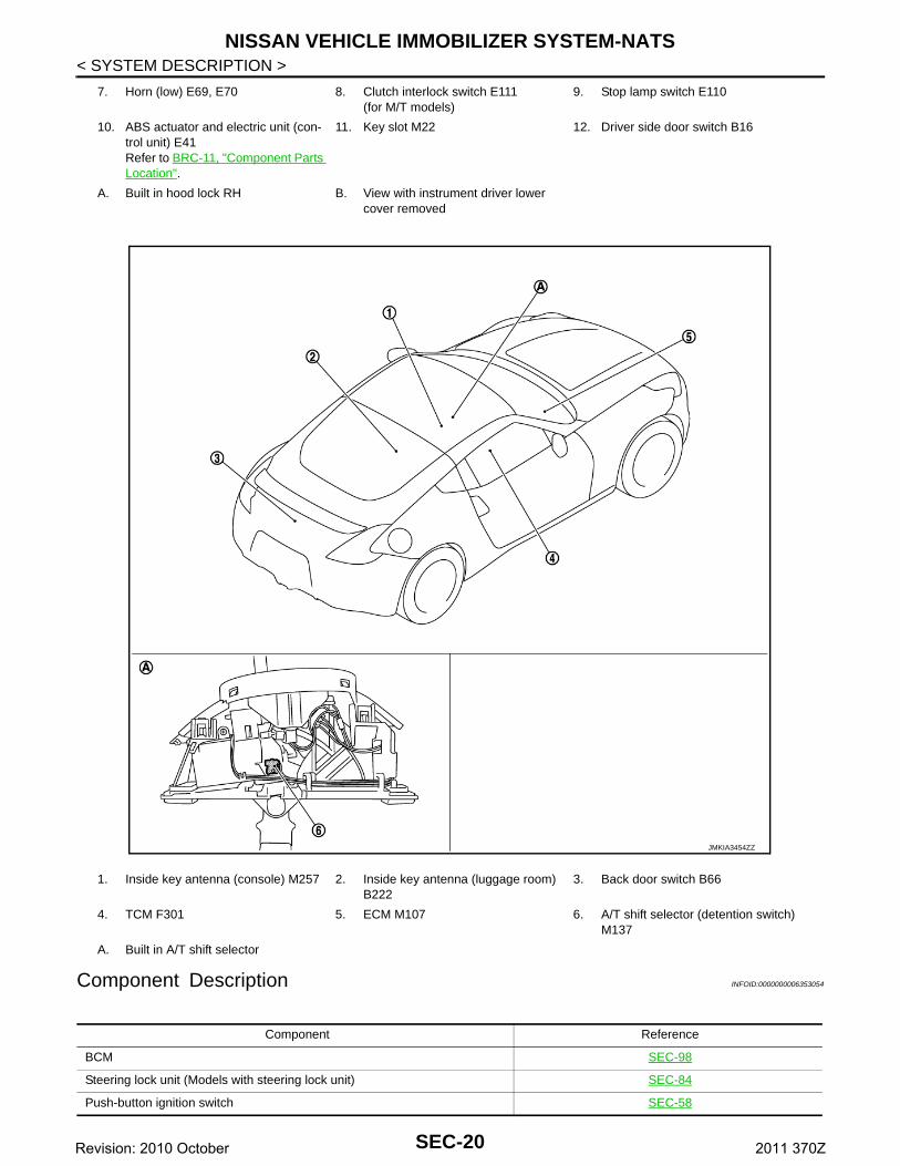
< SYSTEM DESCRIPTION >Component Description INFOID:0000000006353054
7. Horn (low) E69, E70 8. Clutch interlock switch E111(for M/T models)
9. Stop lamp switch E110
10. ABS actuator and electric unit (con-trol unit) E41Refer to BRC-11, "Component Parts Location".
11. Key slot M22 12. Driver side door switch B16
A. Built in hood lock RH B. View with instrument driver lower cover removed
1. Inside key antenna (console) M257 2. Inside key antenna (luggage room) B222
3. Back door switch B66
4. TCM F301 5. ECM M107 6. A/T shift selector (detention switch) M137
A. Built in A/T shift selector
JMKIA3454ZZ
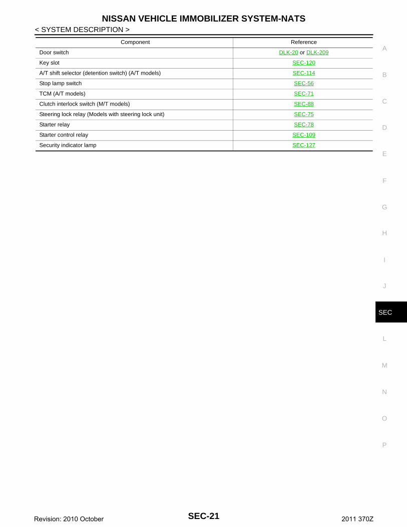
Component Reference
BCM SEC-98
Steering lock unit (Models with steering lock unit) SEC-84
Push-button ignition switch SEC-58
SEC-20Revision: 2010 October 2011 370Z
NISSAN VEHICLE IMMOBILIZER SYSTEM-NATS
C
D
E
F
G
H
I
J
L
M
A
B
EC
N
O
P
< SYSTEM DESCRIPTION >
S
Door switch DLK-20 or DLK-209
Key slot SEC-120
A/T shift selector (detention switch) (A/T models) SEC-114
Stop lamp switch SEC-56
TCM (A/T models) SEC-71
Clutch interlock switch (M/T models) SEC-88
Steering lock relay (Models with steering lock unit) SEC-75
Starter relay SEC-78
Starter control relay SEC-109
Security indicator lamp SEC-127
Component Reference
SEC-21Revision: 2010 October 2011 370Z
VEHICLE SECURITY SYSTEM
< SYSTEM DESCRIPTION >VEHICLE SECURITY SYSTEM
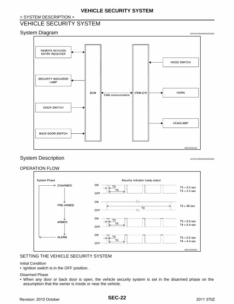
System Diagram INFOID:0000000006353055
System Description INFOID:0000000006353056
OPERATION FLOW
SETTING THE VEHICLE SECURITY SYSTEM
Initial Condition• Ignition switch is in the OFF position.
Disarmed Phase• When any door or back door is open, the vehicle security system is set in the disarmed phase on the
assumption that the owner is inside or near the vehicle.
JMKIA3452GB
JMKIA2505GB
SEC-22Revision: 2010 October 2011 370Z
VEHICLE SECURITY SYSTEM
C
D
E
F
G
H
I
J
L
M
A
B
EC
N
O
P
< SYSTEM DESCRIPTION >
S
• When the vehicle security system is in the disarmed phase, the security indicator lamp blinks every 2.4 sec-onds.
Pre-armed Phase and Armed PhaseWhen the following operation is performed, the vehicle security system turns into the “pre-armed” phase. (Thesecurity indicator lamp illuminates.)1. BCM receives LOCK signal from door request switch or Intelligent Key, after all doors are closed.2. Security indicator lamp illuminates for 30 seconds. Then, the system automatically shifts into the “armed”
phase.
CANCELING THE ARMED PHASE VEHICLE SECURITY SYSTEMWhen one of the following operations is performed, the armed phase is canceled.1. Unlock all doors with the door request switch or Intelligent Key.2. Turn ignition switch “ON” or “ACC” position.
CANCELING THE ALARM OPERATION OF THE VEHICLE SECURITY SYSTEMWhen unlocking all doors with the door request switch or Intelligent Key the alarm operation is canceled.
ACTIVATING THE ALARM OPERATION OF THE VEHICLE SECURITY SYSTEMCheck that the system is in the armed phase. (Security indicator lamp blinks every 2.4 seconds.)When the following operations 1 or 2 is performed, the system sounds the horns and blinks the headlamps forabout 50 seconds.1. Any door or hood is open during the armed phase.2. Disconnecting and connecting the battery connector before canceling the armed phase.
PANIC ALARM FUNCTIONWhen ignition switch is OFF (ignition switch is not pressed) and key switch is OFF (Intelligent Key is notinserted in key slot), BCM receives PANIC ALARM signal from Intelligent Key.BCM turns on and off headlamp intermittently and transmits theft warning horn signal to IPDM E/R. Then,IPDM E/R turns on and off horn intermittently.The headlamp blinks and the horn sounds intermittently.The alarm automatically turns off:• After 25 seconds• When BCM receives any signal from Intelligent KeyPanic alarm function mode can be changed by “PANIC ALARM SET” mode in “WORK SUPPORT” of “INTEL-LIGENT KEY” of “BCM” using CONSULT-III. Refer to SEC-27, "INTELLIGENT KEY : CONSULT-III Function(BCM - INTELLIGENT KEY)".
SEC-23Revision: 2010 October 2011 370Z

VEHICLE SECURITY SYSTEM
< SYSTEM DESCRIPTION >Component Parts Location INFOID:0000000006353057
1. Combination meter M53, M54 2. Push-button ignition switch M50 3. Remote keyless entry receiver M104
4. BCM M118, M119, M121, M122, M123Refer to BCS-8, "Component Parts Location".
5. IPDM E/R E5, E6, E7, E9Refer to PCS-6, "Component Parts Location".
6. Hood switch
7. Horn (low) E69, E70 8. Clutch interlock switch E111(for M/T models)
9. Stop lamp switch E110
10. ABS actuator and electric unit (con-trol unit) E41Refer to BRC-11, "Component Parts Location".
11. Key slot M22 12. Driver side door switch B16
A. Built in hood lock RH B. View with instrument driver lower cover removed
JMKIA3453ZZ
SEC-24Revision: 2010 October 2011 370Z
VEHICLE SECURITY SYSTEM
C
D
E
F
G
H
I
J
L
M
A
B
EC
N
O
P
< SYSTEM DESCRIPTION >
S
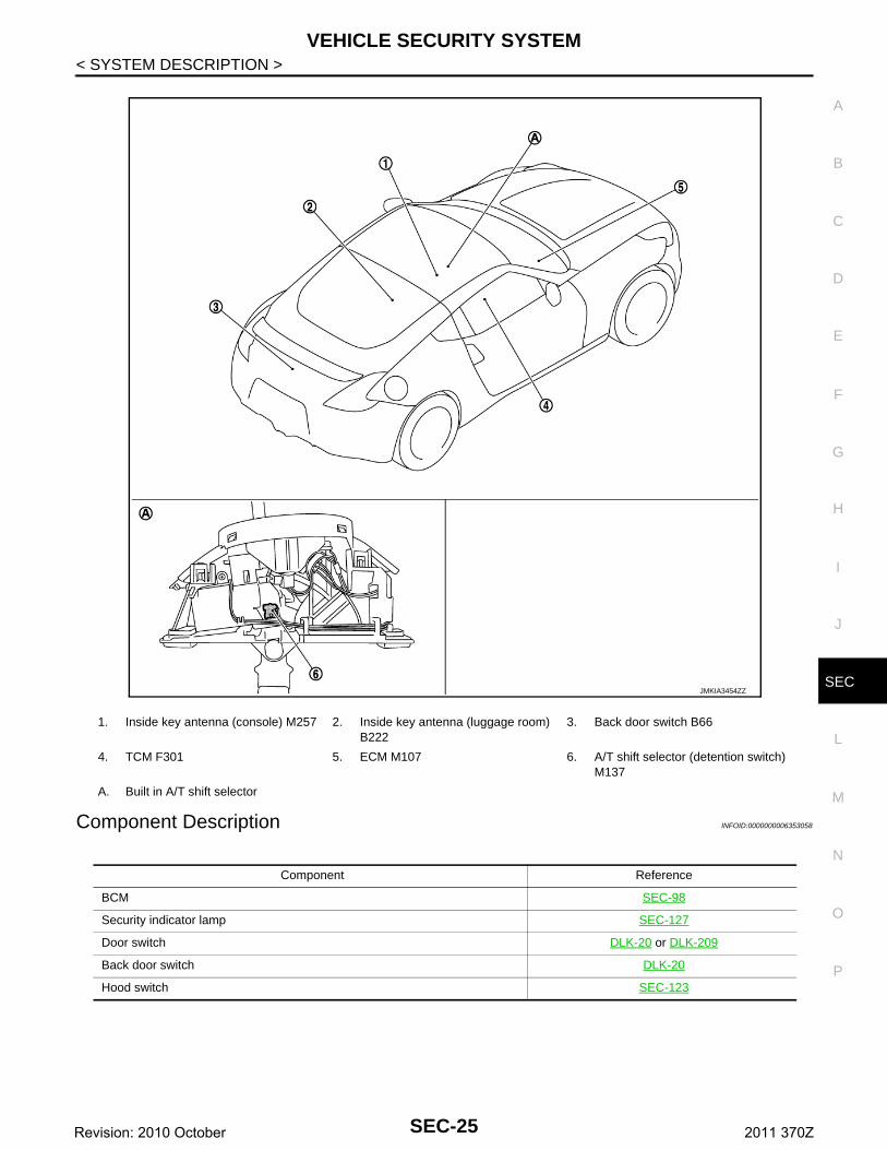
Component Description INFOID:0000000006353058
1. Inside key antenna (console) M257 2. Inside key antenna (luggage room) B222
3. Back door switch B66
4. TCM F301 5. ECM M107 6. A/T shift selector (detention switch) M137
A. Built in A/T shift selector
JMKIA3454ZZ
Component Reference
BCM SEC-98
Security indicator lamp SEC-127
Door switch DLK-20 or DLK-209
Back door switch DLK-20
Hood switch SEC-123
SEC-25Revision: 2010 October 2011 370Z
DIAGNOSIS SYSTEM (BCM)
< SYSTEM DESCRIPTION >DIAGNOSIS SYSTEM (BCM)COMMON ITEM
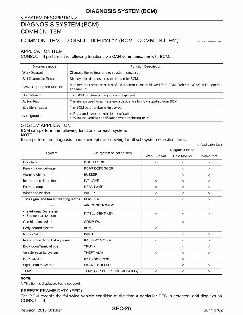
COMMON ITEM : CONSULT-III Function (BCM - COMMON ITEM) INFOID:0000000006921597
APPLICATION ITEMCONSULT-III performs the following functions via CAN communication with BCM.
SYSTEM APPLICATIONBCM can perform the following functions for each system.NOTE:It can perform the diagnosis modes except the following for all sub system selection items.
×: Applicable item
NOTE:
*: This item is displayed, but is not used.
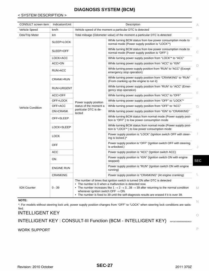
FREEZE FRAME DATA (FFD)The BCM records the following vehicle condition at the time a particular DTC is detected, and displays onCONSULT-III.
Diagnosis mode Function Description
Work Support Changes the setting for each system function.
Self Diagnostic Result Displays the diagnosis results judged by BCM.
CAN Diag Support MonitorMonitors the reception status of CAN communication viewed from BCM. Refer to CONSULT-III opera-tion manual.
Data Monitor The BCM input/output signals are displayed.
Active Test The signals used to activate each device are forcibly supplied from BCM.
Ecu Identification The BCM part number is displayed.
Configuration• Read and save the vehicle specification.• Write the vehicle specification when replacing BCM.
System Sub system selection itemDiagnosis mode
Work Support Data Monitor Active Test
Door lock DOOR LOCK × × ×
Rear window defogger REAR DEFOGGER × ×
Warning chime BUZZER × ×
Interior room lamp timer INT LAMP × × ×
Exterior lamp HEAD LAMP × × ×
Wiper and washer WIPER × × ×
Turn signal and hazard warning lamps FLASHER × × ×
— AIR CONDITONER*
• Intelligent Key system• Engine start system
INTELLIGENT KEY × × ×
Combination switch COMB SW ×
Body control system BCM ×
NVIS - NATS IMMU × ×
Interior room lamp battery saver BATTERY SAVER × × ×
Back door/Trunk lid open TRUNK × ×
Vehicle security system THEFT ALM × × ×
RAP system RETAINED PWR ×
Signal buffer system SIGNAL BUFFER × ×
TPMS TPMS (AIR PRESSURE MONITOR) × × ×
SEC-26Revision: 2010 October 2011 370Z
DIAGNOSIS SYSTEM (BCM)
C
D
E
F
G
H
I
J
L
M
A
B
EC
N
O
P
< SYSTEM DESCRIPTION >
S
NOTE:
*: For models without steering lock unit, power supply position changes from “OFF” to “LOCK” when steering lock conditions are satis-fied.
INTELLIGENT KEY
INTELLIGENT KEY : CONSULT-III Function (BCM - INTELLIGENT KEY) INFOID:0000000006928410
WORK SUPPORT
CONSULT screen item Indication/Unit Description
Vehicle Speed km/h Vehicle speed of the moment a particular DTC is detected
Odo/Trip Meter km Total mileage (Odometer value) of the moment a particular DTC is detected
Vehicle Condition
SLEEP>LOCK
Power supply position status of the moment a particular DTC is de-tected
While turning BCM status from low power consumption mode to normal mode (Power supply position is “LOCK”*)
SLEEP>OFFWhile turning BCM status from low power consumption mode to normal mode (Power supply position is “OFF”.)
LOCK>ACC While turning power supply position from “LOCK”* to “ACC”
ACC>ON While turning power supply position from “ACC” to “IGN”
RUN>ACCWhile turning power supply position from “RUN” to “ACC” (Except emergency stop operation)
CRANK>RUNWhile turning power supply position from “CRANKING” to “RUN” (From cranking up the engine to run it)
RUN>URGENTWhile turning power supply position from “RUN“ to “ACC” (Emer-gency stop operation)
ACC>OFF While turning power supply position from “ACC” to “OFF”
OFF>LOCK While turning power supply position from “OFF” to “LOCK”*
OFF>ACC While turning power supply position from “OFF” to “ACC”
ON>CRANK While turning power supply position from “IGN” to “CRANKING”
OFF>SLEEPWhile turning BCM status from normal mode (Power supply posi-tion is “OFF”.) to low power consumption mode
LOCK>SLEEPWhile turning BCM status from normal mode (Power supply posi-tion is “LOCK”*.) to low power consumption mode
LOCKPower supply position is “LOCK” (Ignition switch OFF with steer-ing is locked.)*
OFFPower supply position is “OFF” (Ignition switch OFF with steering is unlocked.)
ACC Power supply position is “ACC” (Ignition switch ACC)
ONPower supply position is “IGN” (Ignition switch ON with engine stopped)
ENGINE RUNPower supply position is “RUN” (Ignition switch ON with engine running)
CRANKING Power supply position is “CRANKING” (At engine cranking)
IGN Counter 0 - 39
The number of times that ignition switch is turned ON after DTC is detected• The number is 0 when a malfunction is detected now.• The number increases like 1 → 2 → 3...38 → 39 after returning to the normal condition
whenever ignition switch OFF → ON.• The number is fixed to 39 until the self-diagnosis results are erased if it is over 39.
SEC-27Revision: 2010 October 2011 370Z
DIAGNOSIS SYSTEM (BCM)
< SYSTEM DESCRIPTION >*: For roadster models
SELF-DIAG RESULTRefer to BCS-84, "DTC Index".
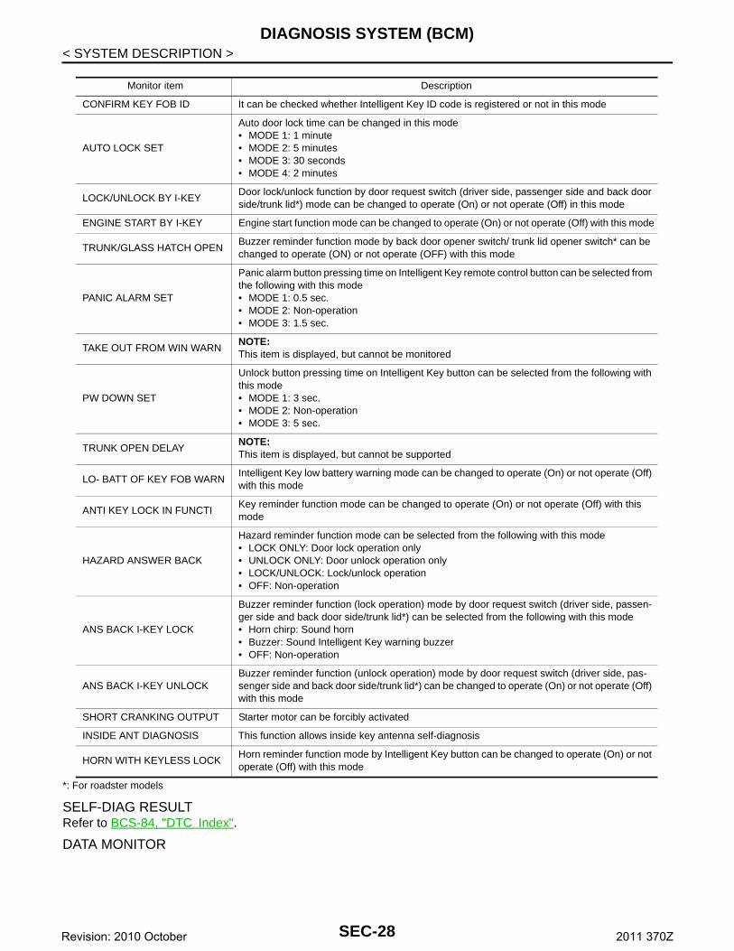
DATA MONITOR
Monitor item Description
CONFIRM KEY FOB ID It can be checked whether Intelligent Key ID code is registered or not in this mode
AUTO LOCK SET
Auto door lock time can be changed in this mode• MODE 1: 1 minute• MODE 2: 5 minutes• MODE 3: 30 seconds• MODE 4: 2 minutes
LOCK/UNLOCK BY I-KEYDoor lock/unlock function by door request switch (driver side, passenger side and back door side/trunk lid*) mode can be changed to operate (On) or not operate (Off) in this mode
ENGINE START BY I-KEY Engine start function mode can be changed to operate (On) or not operate (Off) with this mode
TRUNK/GLASS HATCH OPENBuzzer reminder function mode by back door opener switch/ trunk lid opener switch* can be changed to operate (ON) or not operate (OFF) with this mode
PANIC ALARM SET
Panic alarm button pressing time on Intelligent Key remote control button can be selected from the following with this mode• MODE 1: 0.5 sec.• MODE 2: Non-operation• MODE 3: 1.5 sec.
TAKE OUT FROM WIN WARNNOTE:This item is displayed, but cannot be monitored
PW DOWN SET
Unlock button pressing time on Intelligent Key button can be selected from the following with this mode• MODE 1: 3 sec.• MODE 2: Non-operation• MODE 3: 5 sec.
TRUNK OPEN DELAYNOTE:This item is displayed, but cannot be supported
LO- BATT OF KEY FOB WARNIntelligent Key low battery warning mode can be changed to operate (On) or not operate (Off) with this mode
ANTI KEY LOCK IN FUNCTIKey reminder function mode can be changed to operate (On) or not operate (Off) with this mode
HAZARD ANSWER BACK
Hazard reminder function mode can be selected from the following with this mode• LOCK ONLY: Door lock operation only• UNLOCK ONLY: Door unlock operation only• LOCK/UNLOCK: Lock/unlock operation• OFF: Non-operation
ANS BACK I-KEY LOCK
Buzzer reminder function (lock operation) mode by door request switch (driver side, passen-ger side and back door side/trunk lid*) can be selected from the following with this mode• Horn chirp: Sound horn• Buzzer: Sound Intelligent Key warning buzzer• OFF: Non-operation
ANS BACK I-KEY UNLOCKBuzzer reminder function (unlock operation) mode by door request switch (driver side, pas-senger side and back door side/trunk lid*) can be changed to operate (On) or not operate (Off) with this mode
SHORT CRANKING OUTPUT Starter motor can be forcibly activated
INSIDE ANT DIAGNOSIS This function allows inside key antenna self-diagnosis
HORN WITH KEYLESS LOCKHorn reminder function mode by Intelligent Key button can be changed to operate (On) or not operate (Off) with this mode
SEC-28Revision: 2010 October 2011 370Z
DIAGNOSIS SYSTEM (BCM)
C
D
E
F
G
H
I
J
L
M
A
B
EC
N
O
P
< SYSTEM DESCRIPTION >
S
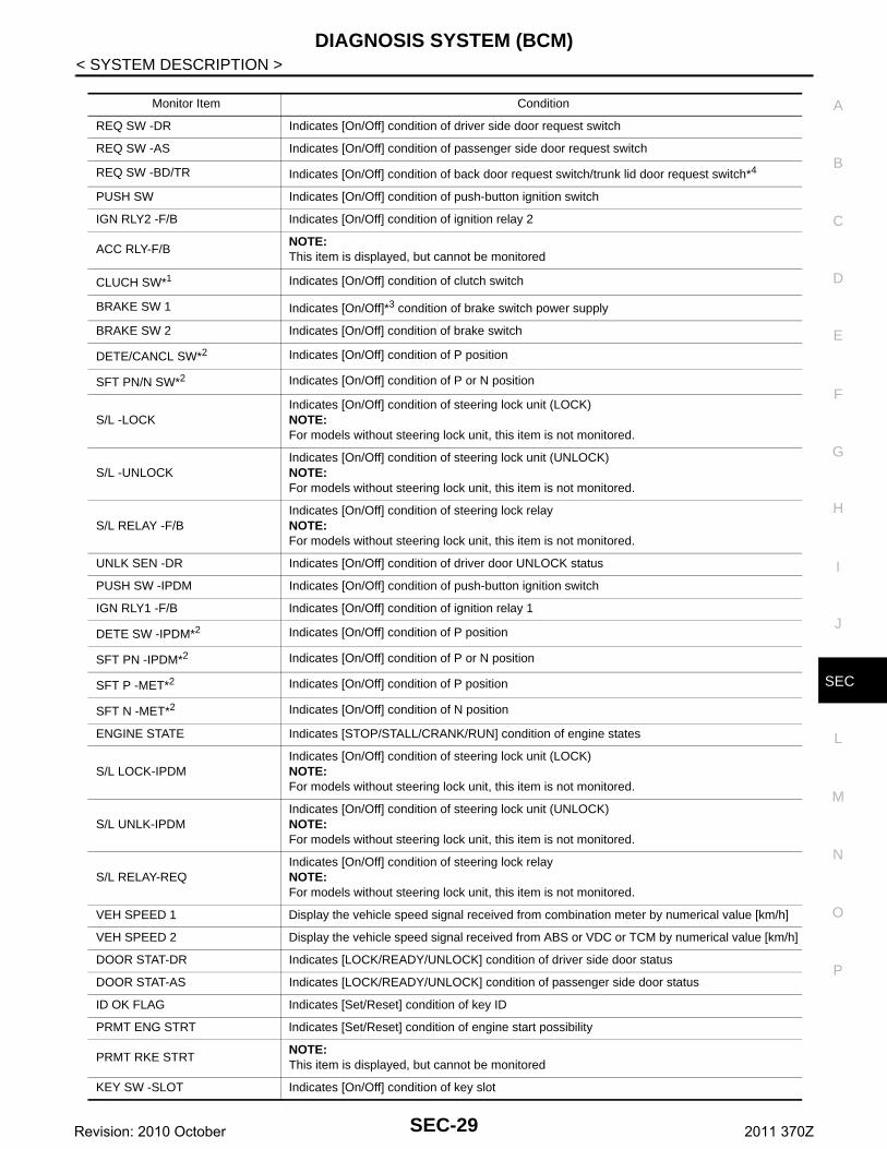
Monitor Item Condition
REQ SW -DR Indicates [On/Off] condition of driver side door request switch
REQ SW -AS Indicates [On/Off] condition of passenger side door request switch
REQ SW -BD/TR Indicates [On/Off] condition of back door request switch/trunk lid door request switch*4
PUSH SW Indicates [On/Off] condition of push-button ignition switch
IGN RLY2 -F/B Indicates [On/Off] condition of ignition relay 2
ACC RLY-F/BNOTE:This item is displayed, but cannot be monitored
CLUCH SW*1 Indicates [On/Off] condition of clutch switch
BRAKE SW 1 Indicates [On/Off]*3 condition of brake switch power supply
BRAKE SW 2 Indicates [On/Off] condition of brake switch
DETE/CANCL SW*2 Indicates [On/Off] condition of P position
SFT PN/N SW*2 Indicates [On/Off] condition of P or N position
S/L -LOCKIndicates [On/Off] condition of steering lock unit (LOCK)NOTE:For models without steering lock unit, this item is not monitored.
S/L -UNLOCKIndicates [On/Off] condition of steering lock unit (UNLOCK)NOTE:For models without steering lock unit, this item is not monitored.
S/L RELAY -F/BIndicates [On/Off] condition of steering lock relayNOTE:For models without steering lock unit, this item is not monitored.
UNLK SEN -DR Indicates [On/Off] condition of driver door UNLOCK status
PUSH SW -IPDM Indicates [On/Off] condition of push-button ignition switch
IGN RLY1 -F/B Indicates [On/Off] condition of ignition relay 1
DETE SW -IPDM*2 Indicates [On/Off] condition of P position
SFT PN -IPDM*2 Indicates [On/Off] condition of P or N position
SFT P -MET*2 Indicates [On/Off] condition of P position
SFT N -MET*2 Indicates [On/Off] condition of N position
ENGINE STATE Indicates [STOP/STALL/CRANK/RUN] condition of engine states
S/L LOCK-IPDMIndicates [On/Off] condition of steering lock unit (LOCK)NOTE:For models without steering lock unit, this item is not monitored.
S/L UNLK-IPDMIndicates [On/Off] condition of steering lock unit (UNLOCK)NOTE:For models without steering lock unit, this item is not monitored.
S/L RELAY-REQIndicates [On/Off] condition of steering lock relayNOTE:For models without steering lock unit, this item is not monitored.
VEH SPEED 1 Display the vehicle speed signal received from combination meter by numerical value [km/h]
VEH SPEED 2 Display the vehicle speed signal received from ABS or VDC or TCM by numerical value [km/h]
DOOR STAT-DR Indicates [LOCK/READY/UNLOCK] condition of driver side door status
DOOR STAT-AS Indicates [LOCK/READY/UNLOCK] condition of passenger side door status
ID OK FLAG Indicates [Set/Reset] condition of key ID
PRMT ENG STRT Indicates [Set/Reset] condition of engine start possibility
PRMT RKE STRTNOTE:This item is displayed, but cannot be monitored
KEY SW -SLOT Indicates [On/Off] condition of key slot
SEC-29Revision: 2010 October 2011 370Z
DIAGNOSIS SYSTEM (BCM)
< SYSTEM DESCRIPTION >*1: It is displayed but does not operate on A/T models.
*2: It is displayed but does not operate on M/T models.
*3: OFF is displayed when brake pedal is depressed while brake switch power supply is OFF.
*4: For roadster models
ACTIVE TEST
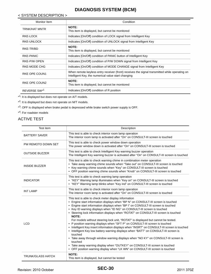
TRNK/HAT MNTRNOTE:This item is displayed, but cannot be monitored
RKE-LOCK Indicates [On/Off] condition of LOCK signal from Intelligent Key
RKE-UNLOCK Indicates [On/Off] condition of UNLOCK signal from Intelligent Key
RKE-TR/BDNOTE:This item is displayed, but cannot be monitored
RKE-PANIC Indicates [On/Off] condition of PANIC button of Intelligent Key
RKE-P/W OPEN Indicates [On/Off] condition of P/W DOWN signal from Intelligent Key
RKE-MODE CHG Indicates [On/Off] condition of MODE CHANGE signal from Intelligent Key
RKE OPE COUN1When remote keyless entry receiver (front) receives the signal transmitted while operating on Intelligent Key, the numerical value start changing
RKE OPE COUN2NOTE:This item is displayed, but cannot be monitored
REVERSE SW*1 Indicates [On/Off] condition of R position
Monitor Item Condition
Test item Description
BATTERY SAVERThis test is able to check interior room lamp operationThe interior room lamp is activated after “On” on CONSULT-III screen is touched
PW REMOTO DOWN SETThis test is able to check power window down operationThe power window down is activated after “On” on CONSULT-III screen is touched
OUTSIDE BUZZERThis test is able to check Intelligent Key warning buzzer operationThe Intelligent Key warning buzzer is activated after “On” on CONSULT-III screen is touched
INSIDE BUZZER
This test is able to check warning chime in combination meter operation• Take away warning chime sounds when “Take out” on CONSULT-III screen is touched• Key warning chime sounds when “Key” on CONSULT-III screen is touched• OFF position warning chime sounds when “Knob” on CONSULT-III screen is touched
INDICATORThis test is able to check warning lamp operation• “KEY” Warning lamp illuminates when “Key on” on CONSULT-III screen is touched• “KEY” Warning lamp blinks when “Key ind” on CONSULT-III screen is touched
INT LAMPThis test is able to check interior room lamp operationThe interior room lamp is activated after “On” on CONSULT-III screen is touched
LCD
This test is able to check meter display information• Engine start information displays when “BP N” on CONSULT-III screen is touched• Engine start information displays when “BP I” on CONSULT-III screen is touched• Key ID warning displays when “ID NG” on CONSULT-III screen is touched• Steering lock information displays when “ROTAT” on CONSULT-III screen is touched
NOTE:For models without steering lock unit, “ROTAT” is displayed but cannot be tested.
• P position warning displays when “SFT P” on CONSULT-III screen is touched• Intelligent Key insert information displays when “INSRT” on CONSULT-III screen is touched• Intelligent Key low battery warning displays when “BATT” on CONSULT-III screen is
touched• Take away through window warning displays when “NO KY” on CONSULT-III screen is
touched• Take away warning display when “OUTKEY” on CONSULT-III screen is touched• OFF position warning display when “LK WN” on CONSULT-III screen is touched
TRUNK/GLASS HATCHNOTE:This item is displayed, but cannot be tested
SEC-30Revision: 2010 October 2011 370Z
DIAGNOSIS SYSTEM (BCM)
C
D
E
F
G
H
I
J
L
M
A
B
EC
N
O
P
< SYSTEM DESCRIPTION >
S
*1: It is displayed but does not operate on M/T models.
*2: For roadster models
THEFT ALM
THEFT ALM : CONSULT-III Function (BCM - THEFT) INFOID:0000000006353061
DATA MONITOR
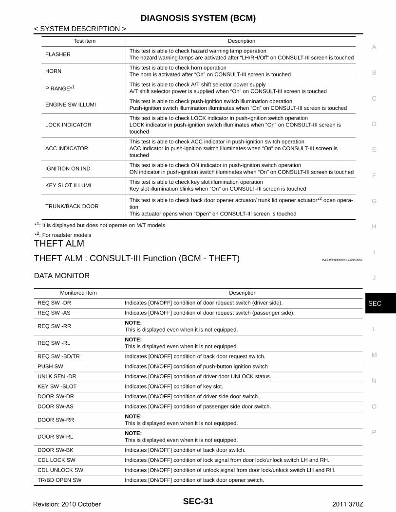
FLASHERThis test is able to check hazard warning lamp operationThe hazard warning lamps are activated after “LH/RH/Off” on CONSULT-III screen is touched
HORNThis test is able to check horn operationThe horn is activated after “On” on CONSULT-III screen is touched
P RANGE*1 This test is able to check A/T shift selector power supplyA/T shift selector power is supplied when “On” on CONSULT-III screen is touched
ENGINE SW ILLUMIThis test is able to check push-ignition switch illumination operationPush-ignition switch illumination illuminates when “On” on CONSULT-III screen is touched
LOCK INDICATORThis test is able to check LOCK indicator in push-ignition switch operationLOCK indicator in push-ignition switch illuminates when “On” on CONSULT-III screen is touched
ACC INDICATORThis test is able to check ACC indicator in push-ignition switch operationACC indicator in push-ignition switch illuminates when “On” on CONSULT-III screen is touched
IGNITION ON INDThis test is able to check ON indicator in push-ignition switch operationON indicator in push-ignition switch illuminates when “On” on CONSULT-III screen is touched
KEY SLOT ILLUMIThis test is able to check key slot illumination operationKey slot illumination blinks when “On” on CONSULT-III screen is touched
TRUNK/BACK DOORThis test is able to check back door opener actuator/ trunk lid opener actuator*2 open opera-tionThis actuator opens when “Open” on CONSULT-III screen is touched
Test item Description
Monitored Item Description
REQ SW -DR Indicates [ON/OFF] condition of door request switch (driver side).
REQ SW -AS Indicates [ON/OFF] condition of door request switch (passenger side).
REQ SW -RRNOTE:This is displayed even when it is not equipped.
REQ SW -RLNOTE:This is displayed even when it is not equipped.
REQ SW -BD/TR Indicates [ON/OFF] condition of back door request switch.
PUSH SW Indicates [ON/OFF] condition of push-button ignition switch
UNLK SEN -DR Indicates [ON/OFF] condition of driver door UNLOCK status.
KEY SW -SLOT Indicates [ON/OFF] condition of key slot.
DOOR SW-DR Indicates [ON/OFF] condition of driver side door switch.
DOOR SW-AS Indicates [ON/OFF] condition of passenger side door switch.
DOOR SW-RRNOTE:This is displayed even when it is not equipped.
DOOR SW-RLNOTE:This is displayed even when it is not equipped.
DOOR SW-BK Indicates [ON/OFF] condition of back door switch.
CDL LOCK SW Indicates [ON/OFF] condition of lock signal from door lock/unlock switch LH and RH.
CDL UNLOCK SW Indicates [ON/OFF] condition of unlock signal from door lock/unlock switch LH and RH.
TR/BD OPEN SW Indicates [ON/OFF] condition of back door opener switch.
SEC-31Revision: 2010 October 2011 370Z
DIAGNOSIS SYSTEM (BCM)
< SYSTEM DESCRIPTION >WORK SUPPORT
ACTIVE TEST
IMMU
IMMU : CONSULT-III Function (BCM - IMMU) INFOID:0000000006353062
DATA MONITOR
ACTIVE TEST
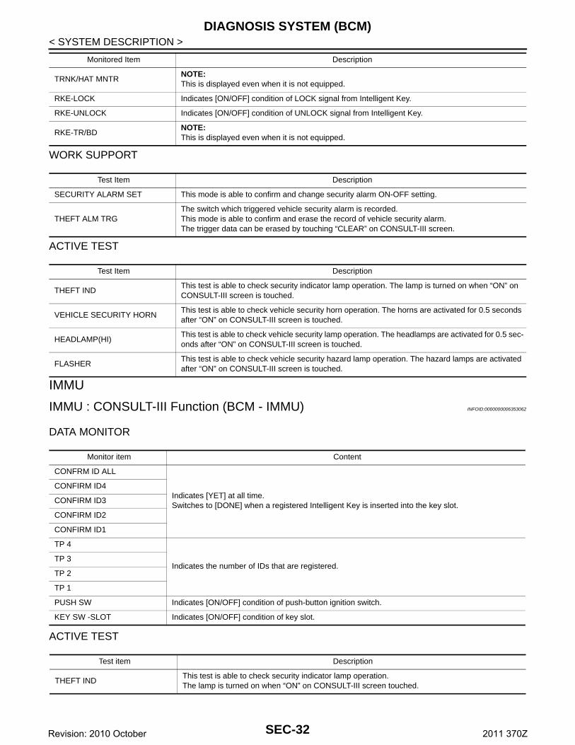
TRNK/HAT MNTRNOTE:This is displayed even when it is not equipped.
RKE-LOCK Indicates [ON/OFF] condition of LOCK signal from Intelligent Key.
RKE-UNLOCK Indicates [ON/OFF] condition of UNLOCK signal from Intelligent Key.
RKE-TR/BDNOTE:This is displayed even when it is not equipped.
Monitored Item Description
Test Item Description
SECURITY ALARM SET This mode is able to confirm and change security alarm ON-OFF setting.
THEFT ALM TRGThe switch which triggered vehicle security alarm is recorded.This mode is able to confirm and erase the record of vehicle security alarm.The trigger data can be erased by touching “CLEAR” on CONSULT-III screen.
Test Item Description
THEFT INDThis test is able to check security indicator lamp operation. The lamp is turned on when “ON” on CONSULT-III screen is touched.
VEHICLE SECURITY HORNThis test is able to check vehicle security horn operation. The horns are activated for 0.5 seconds after “ON” on CONSULT-III screen is touched.
HEADLAMP(HI)This test is able to check vehicle security lamp operation. The headlamps are activated for 0.5 sec-onds after “ON” on CONSULT-III screen is touched.
FLASHERThis test is able to check vehicle security hazard lamp operation. The hazard lamps are activated after “ON” on CONSULT-III screen is touched.
Monitor item Content
CONFRM ID ALL
Indicates [YET] at all time.Switches to [DONE] when a registered Intelligent Key is inserted into the key slot.
CONFIRM ID4
CONFIRM ID3
CONFIRM ID2
CONFIRM ID1
TP 4
Indicates the number of IDs that are registered.TP 3
TP 2
TP 1
PUSH SW Indicates [ON/OFF] condition of push-button ignition switch.
KEY SW -SLOT Indicates [ON/OFF] condition of key slot.
Test item Description
THEFT INDThis test is able to check security indicator lamp operation.The lamp is turned on when “ON” on CONSULT-III screen touched.
SEC-32Revision: 2010 October 2011 370Z
U1000 CAN COMM CIRCUIT
C
D
E
F
G
H
I
J
L
M
A
B
EC
N
O
P
< DTC/CIRCUIT DIAGNOSIS >
S
DTC/CIRCUIT DIAGNOSISU1000 CAN COMM CIRCUITBCM
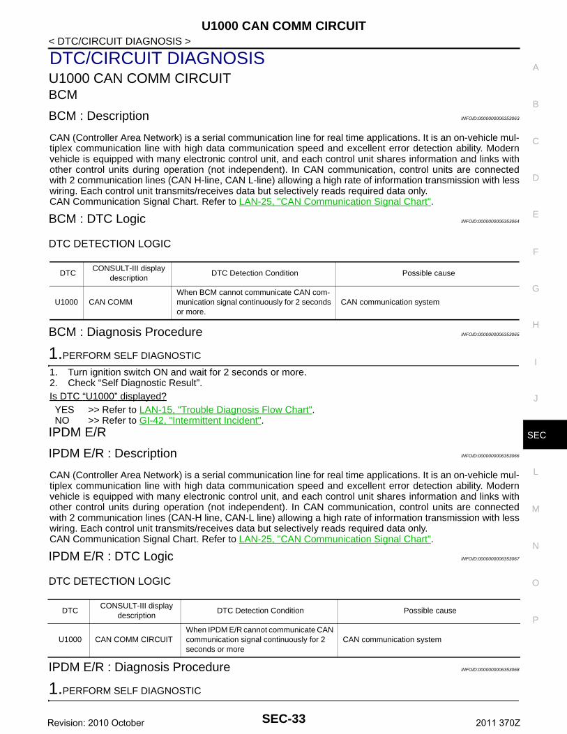
BCM : Description INFOID:0000000006353063
CAN (Controller Area Network) is a serial communication line for real time applications. It is an on-vehicle mul-tiplex communication line with high data communication speed and excellent error detection ability. Modernvehicle is equipped with many electronic control unit, and each control unit shares information and links withother control units during operation (not independent). In CAN communication, control units are connectedwith 2 communication lines (CAN H-line, CAN L-line) allowing a high rate of information transmission with lesswiring. Each control unit transmits/receives data but selectively reads required data only.CAN Communication Signal Chart. Refer to LAN-25, "CAN Communication Signal Chart".
BCM : DTC Logic INFOID:0000000006353064
DTC DETECTION LOGIC
BCM : Diagnosis Procedure INFOID:0000000006353065
1.PERFORM SELF DIAGNOSTIC
1. Turn ignition switch ON and wait for 2 seconds or more.2. Check “Self Diagnostic Result”.Is DTC “U1000” displayed?YES >> Refer to LAN-15, "Trouble Diagnosis Flow Chart".NO >> Refer to GI-42, "Intermittent Incident".
IPDM E/R
IPDM E/R : Description INFOID:0000000006353066
CAN (Controller Area Network) is a serial communication line for real time applications. It is an on-vehicle mul-tiplex communication line with high data communication speed and excellent error detection ability. Modernvehicle is equipped with many electronic control unit, and each control unit shares information and links withother control units during operation (not independent). In CAN communication, control units are connectedwith 2 communication lines (CAN-H line, CAN-L line) allowing a high rate of information transmission with lesswiring. Each control unit transmits/receives data but selectively reads required data only.CAN Communication Signal Chart. Refer to LAN-25, "CAN Communication Signal Chart".
IPDM E/R : DTC Logic INFOID:0000000006353067
DTC DETECTION LOGIC
IPDM E/R : Diagnosis Procedure INFOID:0000000006353068
1.PERFORM SELF DIAGNOSTIC
DTCCONSULT-III display
descriptionDTC Detection Condition Possible cause
U1000 CAN COMMWhen BCM cannot communicate CAN com-munication signal continuously for 2 seconds or more.
CAN communication system
DTCCONSULT-III display
descriptionDTC Detection Condition Possible cause
U1000 CAN COMM CIRCUITWhen IPDM E/R cannot communicate CAN communication signal continuously for 2 seconds or more
CAN communication system
SEC-33Revision: 2010 October 2011 370Z
U1000 CAN COMM CIRCUIT
< DTC/CIRCUIT DIAGNOSIS >1. Turn the ignition switch ON and wait for 2 seconds or more.2. Check “Self Diagnostic Result” of IPDM E/R.Is “CAN COMM CIRCUIT” displayed?YES >> Refer to LAN-15, "Trouble Diagnosis Flow Chart".NO >> Refer to GI-42, "Intermittent Incident".SEC-34Revision: 2010 October 2011 370Z
U1010 CONTROL UNIT (CAN)
C
D
E
F
G
H
I
J
L
M
A
B
EC
N
O
P
< DTC/CIRCUIT DIAGNOSIS >
S
U1010 CONTROL UNIT (CAN)BCM
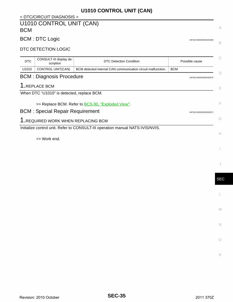
BCM : DTC Logic INFOID:0000000006353069
DTC DETECTION LOGIC
BCM : Diagnosis Procedure INFOID:0000000006353070
1.REPLACE BCM
When DTC “U1010” is detected, replace BCM.
>> Replace BCM. Refer to BCS-90, "Exploded View".
BCM : Special Repair Requirement INFOID:0000000006353071
1.REQUIRED WORK WHEN REPLACING BCM
Initialize control unit. Refer to CONSULT-III operation manual NATS-IVIS/NVIS.
>> Work end.
DTCCONSULT-III display de-
scriptionDTC Detection Condition Possible cause
U1010 CONTROL UNIT(CAN) BCM detected internal CAN communication circuit malfunction. BCM
SEC-35Revision: 2010 October 2011 370Z
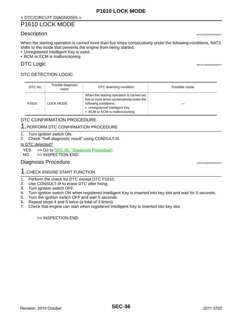
P1610 LOCK MODE
< DTC/CIRCUIT DIAGNOSIS >P1610 LOCK MODE
Description INFOID:0000000006353072
When the starting operation is carried more than five times consecutively under the following conditions, NATSshifts to the mode that prevents the engine from being started.• Unregistered Intelligent Key is used.• BCM or ECM is malfunctioning.
DTC Logic INFOID:0000000006353073
DTC DETECTION LOGIC
DTC CONFIRMATION PROCEDURE
1.PERFORM DTC CONFIRMATION PROCEDURE
1. Turn ignition switch ON.2. Check “Self-diagnostic result” using CONSULT-III.Is DTC detected?YES >> Go to SEC-36, "Diagnosis Procedure".NO >> INSPECTION END
Diagnosis Procedure INFOID:0000000006353074
1.CHECK ENGINE START FUNCTION
1. Perform the check for DTC except DTC P1610.2. Use CONSULT-III to erase DTC after fixing.3. Turn ignition switch OFF.4. Turn ignition switch ON when registered Intelligent Key is inserted into key slot and wait for 5 seconds.5. Turn the ignition switch OFF and wait 5 seconds.6. Repeat steps 4 and 5 twice (a total of 3 times).7. Check that engine can start when registered Intelligent Key is inserted into key slot.
>> INSPECTION END
DTC No.Trouble diagnosis
nameDTC detecting condition Possible cause
P1610 LOCK MODE
When the starting operation is carried out five or more times consecutively under the following conditions.• Unregistered Intelligent Key• BCM or ECM is malfunctioning
—
SEC-36Revision: 2010 October 2011 370Z
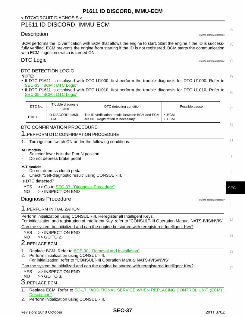
P1611 ID DISCORD, IMMU-ECM
C
D
E
F
G
H
I
J
L
M
A
B
EC
N
O
P
< DTC/CIRCUIT DIAGNOSIS >
S
P1611 ID DISCORD, IMMU-ECM
Description INFOID:0000000006353075
BCM performs the ID verification with ECM that allows the engine to start. Start the engine if the ID is success-fully verified. ECM prevents the engine from starting if the ID is not registered. BCM starts the communicationwith ECM if ignition switch is turned ON.
DTC Logic INFOID:0000000006353076
DTC DETECTION LOGICNOTE:• If DTC P1611 is displayed with DTC U1000, first perform the trouble diagnosis for DTC U1000. Refer to
SEC-33, "BCM : DTC Logic".• If DTC P1611 is displayed with DTC U1010, first perform the trouble diagnosis for DTC U1010. Refer to
SEC-35, "BCM : DTC Logic".
DTC CONFIRMATION PROCEDURE
1.PERFORM DTC CONFIRMATION PROCEDURE
1. Turn ignition switch ON under the following conditions.
A/T models- Selector lever is in the P or N position- Do not depress brake pedal
M/T models- Do not depress clutch pedal2. Check “Self-diagnostic result” using CONSULT-III.Is DTC detected?YES >> Go to SEC-37, "Diagnosis Procedure".NO >> INSPECTION END
Diagnosis Procedure INFOID:0000000006353077
1.PERFORM INITIALIZATION
Perform initialization using CONSULT-III. Reregister all Intelligent Keys.For initialization and registration of Intelligent Key, refer to “CONSULT-III Operation Manual NATS-IVIS/NVIS”.Can the system be initialized and can the engine be started with reregistered Intelligent Key?YES >> INSPECTION ENDNO >> GO TO 2.
2.REPLACE BCM
1. Replace BCM. Refer to BCS-90, "Removal and Installation".2. Perform initialization using CONSULT-III.
For initialization, refer to “CONSULT-III Operation Manual NATS-IVIS/NVIS”.Can the system be initialized and can the engine be started with reregistered Intelligent Key?YES >> INSPECTION ENDNO >> GO TO 3.
3.REPLACE ECM
1. Replace ECM. Refer to EC-17, "ADDITIONAL SERVICE WHEN REPLACING CONTROL UNIT (ECM) :Description".
2. Perform initialization using CONSULT-III.
DTC No.Trouble diagnosis
nameDTC detecting condition Possible cause
P1611ID DISCORD, IMMU-ECM
The ID verification results between BCM and ECM are NG. Registration is necessary.
• BCM• ECM
SEC-37Revision: 2010 October 2011 370Z
P1611 ID DISCORD, IMMU-ECM
< DTC/CIRCUIT DIAGNOSIS >For initialization, refer to “CONSULT-III Operation Manual NATS-IVIS/NVIS”.Can the system be initialized and can the engine be started with reregistered Intelligent Key?YES >> INSPECTION ENDNO >> GO TO 4.
4.CHECK INTERMITTENT INCIDENT
Refer to GI-42, "Intermittent Incident".
>> INSPECTION END
SEC-38Revision: 2010 October 2011 370Z
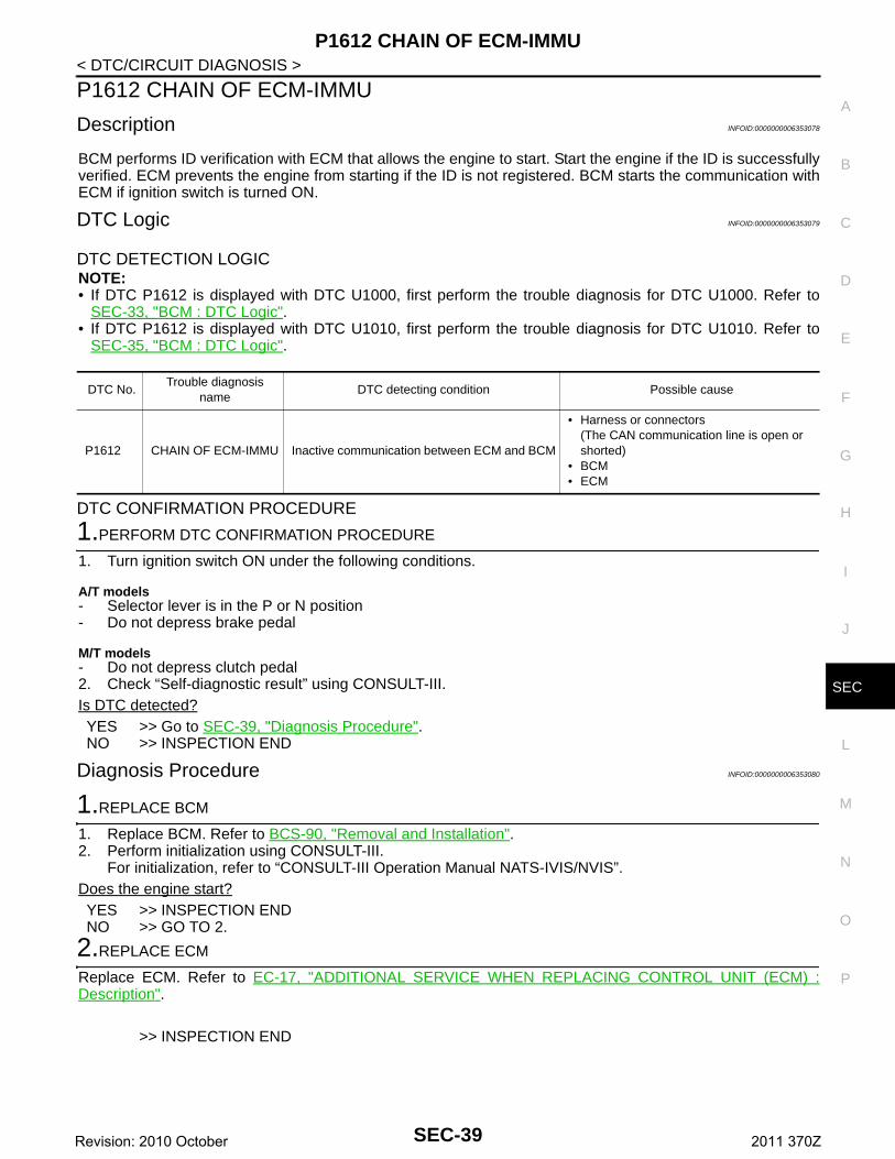
P1612 CHAIN OF ECM-IMMU
C
D
E
F
G
H
I
J
L
M
A
B
EC
N
O
P
< DTC/CIRCUIT DIAGNOSIS >
S
P1612 CHAIN OF ECM-IMMU
Description INFOID:0000000006353078
BCM performs ID verification with ECM that allows the engine to start. Start the engine if the ID is successfullyverified. ECM prevents the engine from starting if the ID is not registered. BCM starts the communication withECM if ignition switch is turned ON.
DTC Logic INFOID:0000000006353079
DTC DETECTION LOGICNOTE:• If DTC P1612 is displayed with DTC U1000, first perform the trouble diagnosis for DTC U1000. Refer to
SEC-33, "BCM : DTC Logic".• If DTC P1612 is displayed with DTC U1010, first perform the trouble diagnosis for DTC U1010. Refer to
SEC-35, "BCM : DTC Logic".
DTC CONFIRMATION PROCEDURE
1.PERFORM DTC CONFIRMATION PROCEDURE
1. Turn ignition switch ON under the following conditions.
A/T models- Selector lever is in the P or N position- Do not depress brake pedal
M/T models- Do not depress clutch pedal2. Check “Self-diagnostic result” using CONSULT-III.Is DTC detected?YES >> Go to SEC-39, "Diagnosis Procedure".NO >> INSPECTION END
Diagnosis Procedure INFOID:0000000006353080
1.REPLACE BCM
1. Replace BCM. Refer to BCS-90, "Removal and Installation".2. Perform initialization using CONSULT-III.
For initialization, refer to “CONSULT-III Operation Manual NATS-IVIS/NVIS”.Does the engine start?YES >> INSPECTION ENDNO >> GO TO 2.
2.REPLACE ECM
Replace ECM. Refer to EC-17, "ADDITIONAL SERVICE WHEN REPLACING CONTROL UNIT (ECM) :Description".
>> INSPECTION END
DTC No.Trouble diagnosis
nameDTC detecting condition Possible cause
P1612 CHAIN OF ECM-IMMU Inactive communication between ECM and BCM
• Harness or connectors(The CAN communication line is open or shorted)
• BCM • ECM
SEC-39Revision: 2010 October 2011 370Z

P1614 CHAIN OF IMMU-KEY
< DTC/CIRCUIT DIAGNOSIS >P1614 CHAIN OF IMMU-KEY
Description INFOID:0000000006353081
Performs ID verification through BCM and Intelligent Key when push-button ignition switch is pressed.Prohibits the release of steering lock (models with steering lock unit) or start of engine when an unregisteredID of Intelligent Key is used.
DTC Logic INFOID:0000000006353082
DTC DETECTION LOGIC
DTC CONFIRMATION PROCEDURE
1.PERFORM DTC CONFIRMATION PROCEDURE 1
1. Insert Intelligent Key into the key slot.2. Check “Self-diagnostic result” using CONSULT-III.Is DTC detected?YES >> Go to SEC-40, "Diagnosis Procedure".NO >> GO TO 2.
2.PERFORM DTC CONFIRMATION PROCEDURE 2
1. Press the push-button ignition switch.2. Check “Self-diagnostic result” using CONSULT-III.Is DTC detected?YES >> Go to SEC-40, "Diagnosis Procedure".NO >> INSPECTION END
Diagnosis Procedure INFOID:0000000006353083
1. INSPECTION START
Perform inspection in accordance with procedure that confirms DTC.Which procedure confirms DTC?DTC confirmation procedure 1>>GO TO 2.DTC confirmation procedure 2>>GO TO 4.
2.CHECK KEY SLOT INPUT SIGNAL
1. Turn ignition switch OFF.2. Disconnect key slot connector.3. Check voltage between key slot harness connector and ground.
Is the inspection result normal?YES >> Replace key slot. Refer to SEC-224, "Removal and Installation".NO >> GO TO 3.
DTC No.Trouble diagnosis
nameDTC detecting condition Possible cause
P1614CHAIN OF IMMU-KEY
Inactive communication between key slot and BCM.
• Harness or connectors(The key slot circuit is open or shorted)
• Key slot • BCM
(+)
(–)Voltage (V)(Approx.)
Key slot
Connector Terminal
M22 2 Ground Battery voltage
SEC-40Revision: 2010 October 2011 370Z
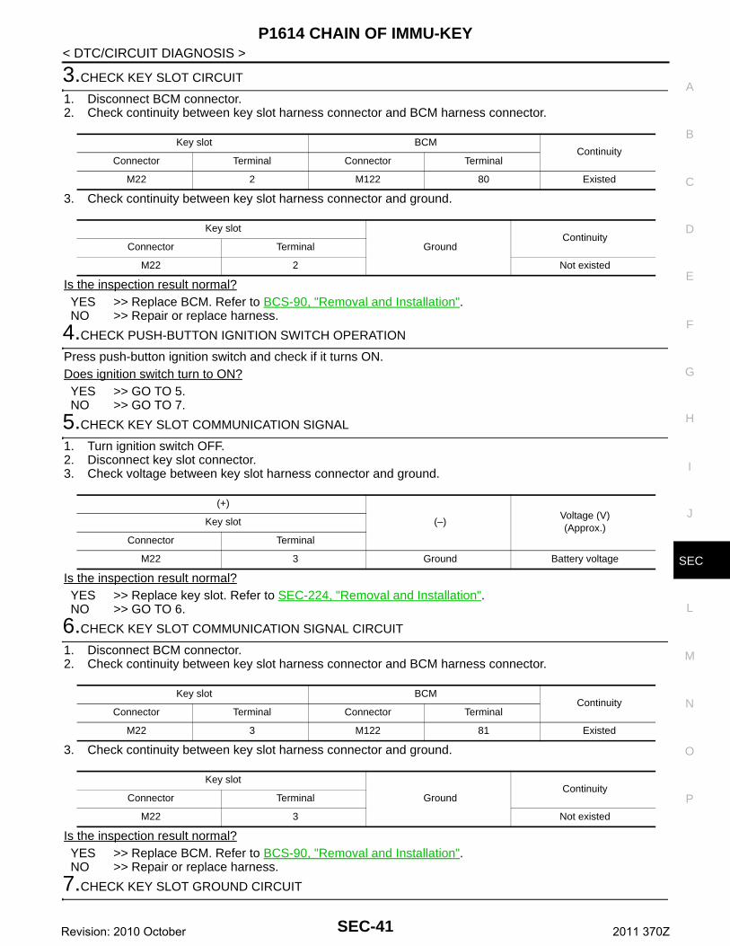
P1614 CHAIN OF IMMU-KEY
C
D
E
F
G
H
I
J
L
M
A
B
EC
N
O
P
< DTC/CIRCUIT DIAGNOSIS >
S
3.CHECK KEY SLOT CIRCUIT
1. Disconnect BCM connector.2. Check continuity between key slot harness connector and BCM harness connector.
3. Check continuity between key slot harness connector and ground.
Is the inspection result normal?YES >> Replace BCM. Refer to BCS-90, "Removal and Installation".NO >> Repair or replace harness.
4.CHECK PUSH-BUTTON IGNITION SWITCH OPERATION
Press push-button ignition switch and check if it turns ON.Does ignition switch turn to ON?YES >> GO TO 5.NO >> GO TO 7.
5.CHECK KEY SLOT COMMUNICATION SIGNAL
1. Turn ignition switch OFF.2. Disconnect key slot connector.3. Check voltage between key slot harness connector and ground.
Is the inspection result normal?YES >> Replace key slot. Refer to SEC-224, "Removal and Installation".NO >> GO TO 6.
6.CHECK KEY SLOT COMMUNICATION SIGNAL CIRCUIT
1. Disconnect BCM connector.2. Check continuity between key slot harness connector and BCM harness connector.
3. Check continuity between key slot harness connector and ground.
Is the inspection result normal?YES >> Replace BCM. Refer to BCS-90, "Removal and Installation".NO >> Repair or replace harness.
7.CHECK KEY SLOT GROUND CIRCUIT
Key slot BCMContinuity
Connector Terminal Connector Terminal
M22 2 M122 80 Existed
Key slot
GroundContinuity
Connector Terminal
M22 2 Not existed
(+)
(–)Voltage (V)(Approx.)
Key slot
Connector Terminal
M22 3 Ground Battery voltage
Key slot BCMContinuity
Connector Terminal Connector Terminal
M22 3 M122 81 Existed
Key slot
GroundContinuity
Connector Terminal
M22 3 Not existed
SEC-41Revision: 2010 October 2011 370Z
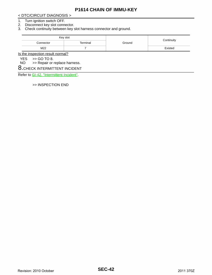
P1614 CHAIN OF IMMU-KEY
< DTC/CIRCUIT DIAGNOSIS >1. Turn ignition switch OFF.2. Disconnect key slot connector.3. Check continuity between key slot harness connector and ground.Is the inspection result normal?YES >> GO TO 8.NO >> Repair or replace harness.
8.CHECK INTERMITTENT INCIDENT
Refer to GI-42, "Intermittent Incident".
>> INSPECTION END
Key slot
GroundContinuity
Connector Terminal
M22 7 Existed
SEC-42Revision: 2010 October 2011 370Z
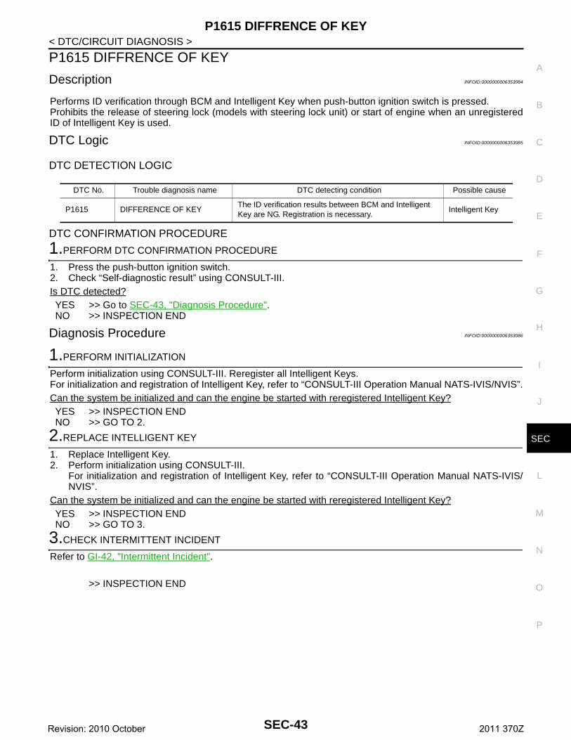
P1615 DIFFRENCE OF KEY
C
D
E
F
G
H
I
J
L
M
A
B
EC
N
O
P
< DTC/CIRCUIT DIAGNOSIS >
S
P1615 DIFFRENCE OF KEY
Description INFOID:0000000006353084
Performs ID verification through BCM and Intelligent Key when push-button ignition switch is pressed.Prohibits the release of steering lock (models with steering lock unit) or start of engine when an unregisteredID of Intelligent Key is used.
DTC Logic INFOID:0000000006353085
DTC DETECTION LOGIC
DTC CONFIRMATION PROCEDURE
1.PERFORM DTC CONFIRMATION PROCEDURE
1. Press the push-button ignition switch.2. Check “Self-diagnostic result” using CONSULT-III.Is DTC detected?YES >> Go to SEC-43, "Diagnosis Procedure".NO >> INSPECTION END
Diagnosis Procedure INFOID:0000000006353086
1.PERFORM INITIALIZATION
Perform initialization using CONSULT-III. Reregister all Intelligent Keys.For initialization and registration of Intelligent Key, refer to “CONSULT-III Operation Manual NATS-IVIS/NVIS”.Can the system be initialized and can the engine be started with reregistered Intelligent Key?YES >> INSPECTION ENDNO >> GO TO 2.
2.REPLACE INTELLIGENT KEY
1. Replace Intelligent Key.2. Perform initialization using CONSULT-III.
For initialization and registration of Intelligent Key, refer to “CONSULT-III Operation Manual NATS-IVIS/NVIS”.
Can the system be initialized and can the engine be started with reregistered Intelligent Key?YES >> INSPECTION ENDNO >> GO TO 3.
3.CHECK INTERMITTENT INCIDENT
Refer to GI-42, "Intermittent Incident".
>> INSPECTION END
DTC No. Trouble diagnosis name DTC detecting condition Possible cause
P1615 DIFFERENCE OF KEYThe ID verification results between BCM and Intelligent Key are NG. Registration is necessary.
Intelligent Key
SEC-43Revision: 2010 October 2011 370Z
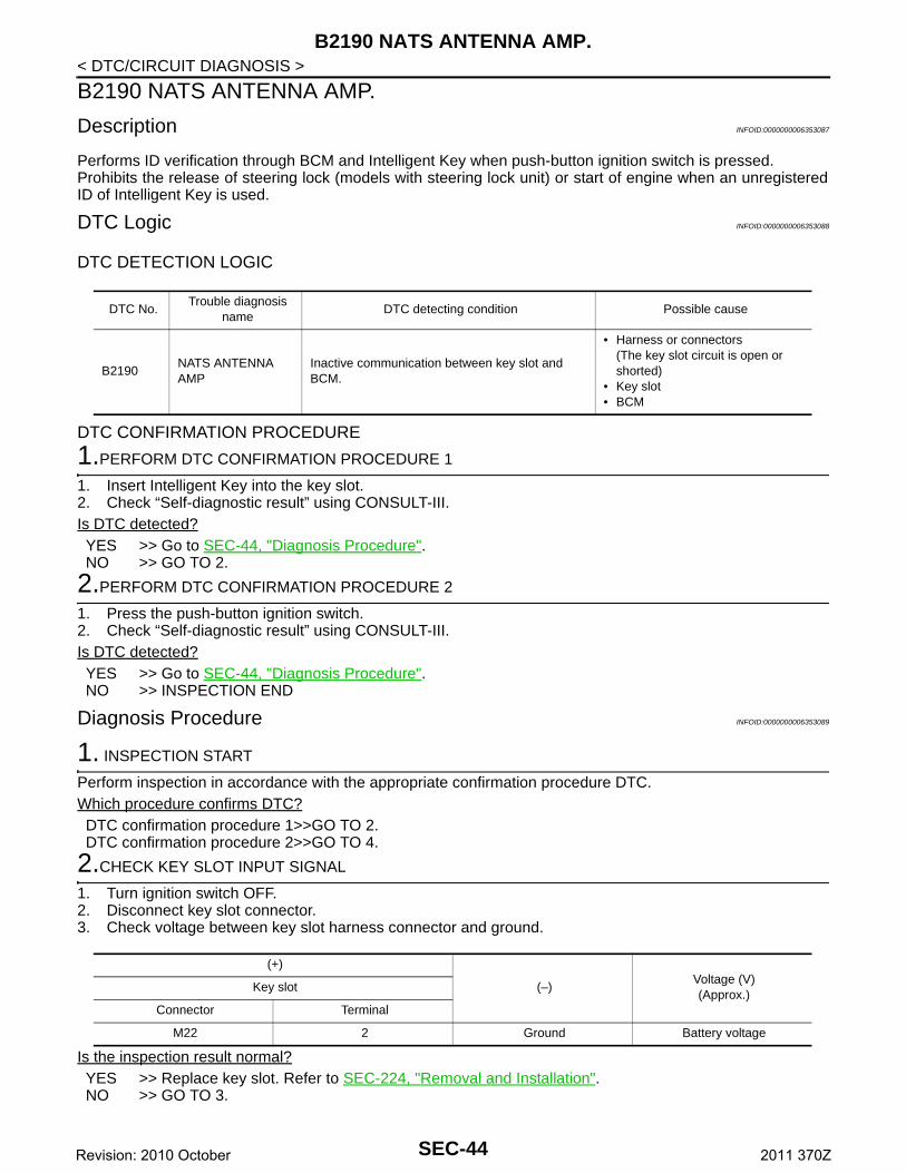
B2190 NATS ANTENNA AMP.
< DTC/CIRCUIT DIAGNOSIS >B2190 NATS ANTENNA AMP.
Description INFOID:0000000006353087
Performs ID verification through BCM and Intelligent Key when push-button ignition switch is pressed.Prohibits the release of steering lock (models with steering lock unit) or start of engine when an unregisteredID of Intelligent Key is used.
DTC Logic INFOID:0000000006353088
DTC DETECTION LOGIC
DTC CONFIRMATION PROCEDURE
1.PERFORM DTC CONFIRMATION PROCEDURE 1
1. Insert Intelligent Key into the key slot.2. Check “Self-diagnostic result” using CONSULT-III.Is DTC detected?YES >> Go to SEC-44, "Diagnosis Procedure".NO >> GO TO 2.
2.PERFORM DTC CONFIRMATION PROCEDURE 2
1. Press the push-button ignition switch.2. Check “Self-diagnostic result” using CONSULT-III.Is DTC detected?YES >> Go to SEC-44, "Diagnosis Procedure".NO >> INSPECTION END
Diagnosis Procedure INFOID:0000000006353089
1. INSPECTION START
Perform inspection in accordance with the appropriate confirmation procedure DTC.Which procedure confirms DTC?DTC confirmation procedure 1>>GO TO 2.DTC confirmation procedure 2>>GO TO 4.
2.CHECK KEY SLOT INPUT SIGNAL
1. Turn ignition switch OFF.2. Disconnect key slot connector.3. Check voltage between key slot harness connector and ground.
Is the inspection result normal?YES >> Replace key slot. Refer to SEC-224, "Removal and Installation".NO >> GO TO 3.
DTC No.Trouble diagnosis
nameDTC detecting condition Possible cause
B2190NATS ANTENNA AMP
Inactive communication between key slot and BCM.
• Harness or connectors(The key slot circuit is open or shorted)
• Key slot • BCM
(+)
(–)Voltage (V)(Approx.)
Key slot
Connector Terminal
M22 2 Ground Battery voltage
SEC-44Revision: 2010 October 2011 370Z

B2190 NATS ANTENNA AMP.
C
D
E
F
G
H
I
J
L
M
A
B
EC
N
O
P
< DTC/CIRCUIT DIAGNOSIS >
S
3.CHECK KEY SLOT CIRCUIT
1. Disconnect BCM connector.2. Check continuity between key slot harness connector and BCM harness connector.
3. Check continuity between key slot harness connector and ground.
Is the inspection result normal?YES >> Replace BCM. Refer to BCS-90, "Removal and Installation".NO >> Repair or replace harness.
4.CHECK PUSH-BUTTON IGNITION SWITCH OPERATION
Press push-button ignition switch and check if it turns ON.Does ignition switch turn to ON?YES >> GO TO 5.NO >> GO TO 7.
5.CHECK KEY SLOT COMMUNICATION SIGNAL
1. Turn ignition switch OFF.2. Disconnect key slot connector.3. Check voltage between key slot harness connector and ground.
Is the inspection result normal?YES >> Replace key slot. Refer to SEC-224, "Removal and Installation".NO >> GO TO 6.
6.CHECK KEY SLOT COMMUNICATION SIGNAL CIRCUIT
1. Disconnect BCM connector.2. Check continuity between key slot harness connector and BCM harness connector.
3. Check continuity between key slot harness connector and ground.
Is the inspection result normal?YES >> Replace BCM. Refer to BCS-90, "Removal and Installation".NO >> Repair or replace harness.
7.CHECK KEY SLOT GROUND CIRCUIT
Key slot BCMContinuity
Connector Terminal Connector Terminal
M22 2 M122 80 Existed
Key slot
GroundContinuity
Connector Terminal
M22 2 Not existed
(+)
(–)Voltage (V)(Approx.)
Key slot
Connector Terminal
M22 3 Ground Battery voltage
Key slot BCMContinuity
Connector Terminal Connector Terminal
M22 3 M122 81 Existed
Key slot
GroundContinuity
Connector Terminal
M22 3 Not existed
SEC-45Revision: 2010 October 2011 370Z
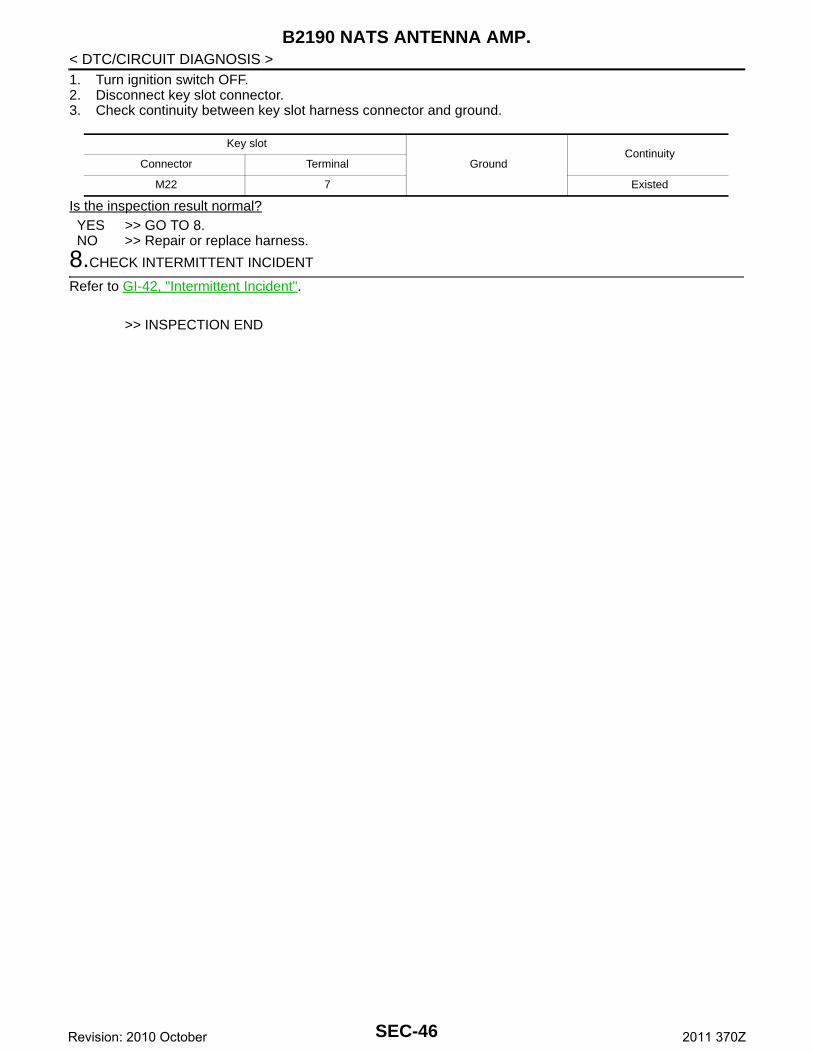
B2190 NATS ANTENNA AMP.
< DTC/CIRCUIT DIAGNOSIS >1. Turn ignition switch OFF.2. Disconnect key slot connector.3. Check continuity between key slot harness connector and ground.Is the inspection result normal?YES >> GO TO 8.NO >> Repair or replace harness.
8.CHECK INTERMITTENT INCIDENT
Refer to GI-42, "Intermittent Incident".
>> INSPECTION END
Key slot
GroundContinuity
Connector Terminal
M22 7 Existed
SEC-46Revision: 2010 October 2011 370Z

B2191 DIFFERENCE OF KEY
C
D
E
F
G
H
I
J
L
M
A
B
EC
N
O
P
< DTC/CIRCUIT DIAGNOSIS >
S
B2191 DIFFERENCE OF KEY
Description INFOID:0000000006353090
Performs ID verification through BCM and Intelligent Key when push-button ignition switch is pressed.Prohibits the release of steering lock (models with steering lock unit) or start of engine when an unregisteredID of Intelligent Key is used.
DTC Logic INFOID:0000000006353091
DTC DETECTION LOGIC
DTC CONFIRMATION PROCEDURE
1.PERFORM DTC CONFIRMATION PROCEDURE
1. Press the push-button ignition switch.2. Check “Self-diagnostic result” using CONSULT-III.Is DTC detected?YES >> Go to SEC-47, "Diagnosis Procedure".NO >> INSPECTION END
Diagnosis Procedure INFOID:0000000006353092
1.PERFORM INITIALIZATION
Perform initialization using CONSULT-III. Reregister all Intelligent Keys.For initialization and registration of Intelligent Key, refer to “CONSULT-III Operation Manual NATS-IVIS/NVIS”.Can the system be initialized and can the engine be started with reregistered Intelligent Key?YES >> INSPECTION ENDNO >> GO TO 2.
2.REPLACE INTELLIGENT KEY
1. Replace Intelligent Key.2. Perform initialization using CONSULT-III.
For initialization and registration of Intelligent Key, refer to “CONSULT-III Operation Manual NATS-IVIS/NVIS”.
Can the system be initialized and can the engine be started with reregistered Intelligent Key?YES >> INSPECTION ENDNO >> GO TO 3.
3.CHECK INTERMITTENT INCIDENT
Refer to GI-42, "Intermittent Incident".
>> INSPECTION END
DTC No. Trouble diagnosis name DTC detecting condition Possible cause
B2191 DIFFERENCE OF KEYThe ID verification results between BCM and Intelligent Key are NG. Registration is necessary.
Intelligent Key
SEC-47Revision: 2010 October 2011 370Z
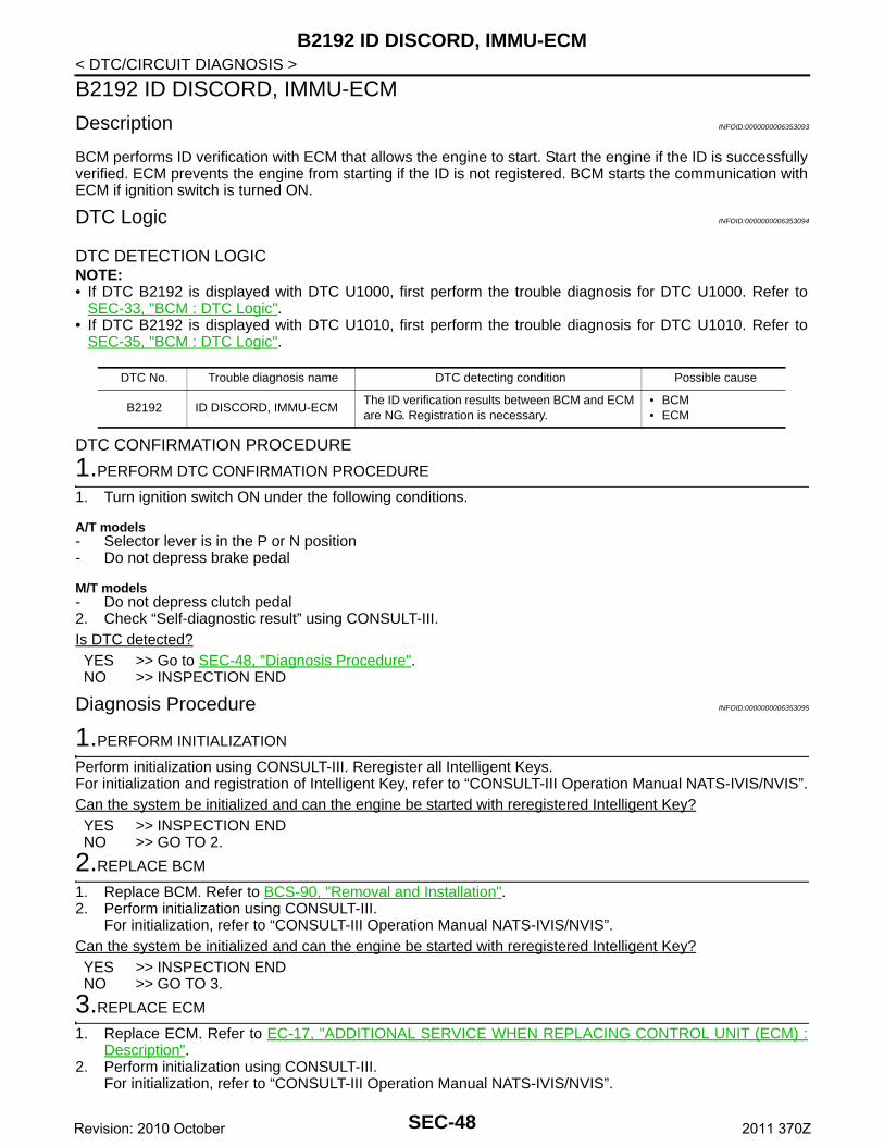
B2192 ID DISCORD, IMMU-ECM
< DTC/CIRCUIT DIAGNOSIS >B2192 ID DISCORD, IMMU-ECM
Description INFOID:0000000006353093
BCM performs ID verification with ECM that allows the engine to start. Start the engine if the ID is successfullyverified. ECM prevents the engine from starting if the ID is not registered. BCM starts the communication withECM if ignition switch is turned ON.
DTC Logic INFOID:0000000006353094
DTC DETECTION LOGICNOTE:• If DTC B2192 is displayed with DTC U1000, first perform the trouble diagnosis for DTC U1000. Refer to
SEC-33, "BCM : DTC Logic".• If DTC B2192 is displayed with DTC U1010, first perform the trouble diagnosis for DTC U1010. Refer to
SEC-35, "BCM : DTC Logic".
DTC CONFIRMATION PROCEDURE
1.PERFORM DTC CONFIRMATION PROCEDURE
1. Turn ignition switch ON under the following conditions.
A/T models- Selector lever is in the P or N position- Do not depress brake pedal
M/T models- Do not depress clutch pedal2. Check “Self-diagnostic result” using CONSULT-III.Is DTC detected?YES >> Go to SEC-48, "Diagnosis Procedure".NO >> INSPECTION END
Diagnosis Procedure INFOID:0000000006353095
1.PERFORM INITIALIZATION
Perform initialization using CONSULT-III. Reregister all Intelligent Keys.For initialization and registration of Intelligent Key, refer to “CONSULT-III Operation Manual NATS-IVIS/NVIS”.Can the system be initialized and can the engine be started with reregistered Intelligent Key?YES >> INSPECTION ENDNO >> GO TO 2.
2.REPLACE BCM
1. Replace BCM. Refer to BCS-90, "Removal and Installation".2. Perform initialization using CONSULT-III.
For initialization, refer to “CONSULT-III Operation Manual NATS-IVIS/NVIS”.Can the system be initialized and can the engine be started with reregistered Intelligent Key?YES >> INSPECTION ENDNO >> GO TO 3.
3.REPLACE ECM
1. Replace ECM. Refer to EC-17, "ADDITIONAL SERVICE WHEN REPLACING CONTROL UNIT (ECM) :Description".
2. Perform initialization using CONSULT-III. For initialization, refer to “CONSULT-III Operation Manual NATS-IVIS/NVIS”.
DTC No. Trouble diagnosis name DTC detecting condition Possible cause
B2192 ID DISCORD, IMMU-ECMThe ID verification results between BCM and ECM are NG. Registration is necessary.
• BCM• ECM
SEC-48Revision: 2010 October 2011 370Z
B2192 ID DISCORD, IMMU-ECM
C
D
E
F
G
H
I
J
L
M
A
B
EC
N
O
P
< DTC/CIRCUIT DIAGNOSIS >
S
Can the system be initialized and can the engine be started with reregistered Intelligent Key?YES >> INSPECTION ENDNO >> GO TO 4.
4.CHECK INTERMITTENT INCIDENT
Refer to GI-42, "Intermittent Incident".
>> INSPECTION END
SEC-49Revision: 2010 October 2011 370Z
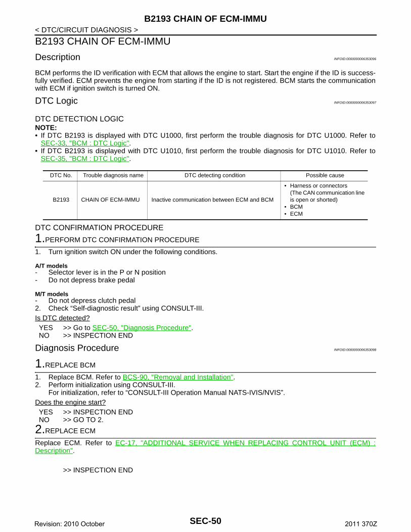
B2193 CHAIN OF ECM-IMMU
< DTC/CIRCUIT DIAGNOSIS >B2193 CHAIN OF ECM-IMMU
Description INFOID:0000000006353096
BCM performs the ID verification with ECM that allows the engine to start. Start the engine if the ID is success-fully verified. ECM prevents the engine from starting if the ID is not registered. BCM starts the communicationwith ECM if ignition switch is turned ON.
DTC Logic INFOID:0000000006353097
DTC DETECTION LOGICNOTE:• If DTC B2193 is displayed with DTC U1000, first perform the trouble diagnosis for DTC U1000. Refer to
SEC-33, "BCM : DTC Logic".• If DTC B2193 is displayed with DTC U1010, first perform the trouble diagnosis for DTC U1010. Refer to
SEC-35, "BCM : DTC Logic".
DTC CONFIRMATION PROCEDURE
1.PERFORM DTC CONFIRMATION PROCEDURE
1. Turn ignition switch ON under the following conditions.
A/T models- Selector lever is in the P or N position- Do not depress brake pedal
M/T models- Do not depress clutch pedal2. Check “Self-diagnostic result” using CONSULT-III.Is DTC detected?YES >> Go to SEC-50, "Diagnosis Procedure".NO >> INSPECTION END
Diagnosis Procedure INFOID:0000000006353098
1.REPLACE BCM
1. Replace BCM. Refer to BCS-90, "Removal and Installation".2. Perform initialization using CONSULT-III.
For initialization, refer to “CONSULT-III Operation Manual NATS-IVIS/NVIS”.Does the engine start?YES >> INSPECTION ENDNO >> GO TO 2.
2.REPLACE ECM
Replace ECM. Refer to EC-17, "ADDITIONAL SERVICE WHEN REPLACING CONTROL UNIT (ECM) :Description".
>> INSPECTION END
DTC No. Trouble diagnosis name DTC detecting condition Possible cause
B2193 CHAIN OF ECM-IMMU Inactive communication between ECM and BCM
• Harness or connectors(The CAN communication line is open or shorted)
• BCM • ECM
SEC-50Revision: 2010 October 2011 370Z
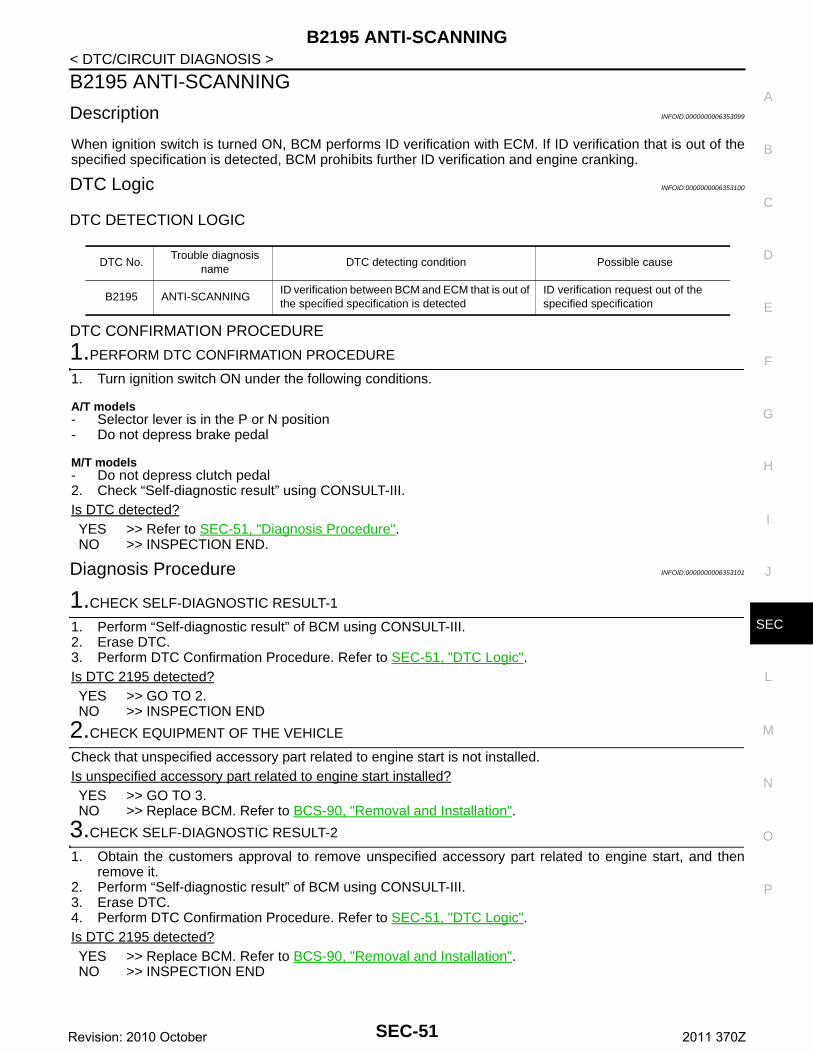
B2195 ANTI-SCANNING
C
D
E
F
G
H
I
J
L
M
A
B
EC
N
O
P
< DTC/CIRCUIT DIAGNOSIS >
S
B2195 ANTI-SCANNING
Description INFOID:0000000006353099
When ignition switch is turned ON, BCM performs ID verification with ECM. If ID verification that is out of thespecified specification is detected, BCM prohibits further ID verification and engine cranking.
DTC Logic INFOID:0000000006353100
DTC DETECTION LOGIC
DTC CONFIRMATION PROCEDURE
1.PERFORM DTC CONFIRMATION PROCEDURE
1. Turn ignition switch ON under the following conditions.
A/T models- Selector lever is in the P or N position- Do not depress brake pedal
M/T models- Do not depress clutch pedal2. Check “Self-diagnostic result” using CONSULT-III.Is DTC detected?YES >> Refer to SEC-51, "Diagnosis Procedure".NO >> INSPECTION END.
Diagnosis Procedure INFOID:0000000006353101
1.CHECK SELF-DIAGNOSTIC RESULT-1
1. Perform “Self-diagnostic result” of BCM using CONSULT-III.2. Erase DTC.3. Perform DTC Confirmation Procedure. Refer to SEC-51, "DTC Logic".Is DTC 2195 detected?YES >> GO TO 2.NO >> INSPECTION END
2.CHECK EQUIPMENT OF THE VEHICLE
Check that unspecified accessory part related to engine start is not installed.Is unspecified accessory part related to engine start installed?YES >> GO TO 3.NO >> Replace BCM. Refer to BCS-90, "Removal and Installation".
3.CHECK SELF-DIAGNOSTIC RESULT-2
1. Obtain the customers approval to remove unspecified accessory part related to engine start, and thenremove it.
2. Perform “Self-diagnostic result” of BCM using CONSULT-III.3. Erase DTC.4. Perform DTC Confirmation Procedure. Refer to SEC-51, "DTC Logic".Is DTC 2195 detected?YES >> Replace BCM. Refer to BCS-90, "Removal and Installation".NO >> INSPECTION END
DTC No.Trouble diagnosis
nameDTC detecting condition Possible cause
B2195 ANTI-SCANNINGID verification between BCM and ECM that is out of the specified specification is detected
ID verification request out of the specified specification
SEC-51Revision: 2010 October 2011 370Z
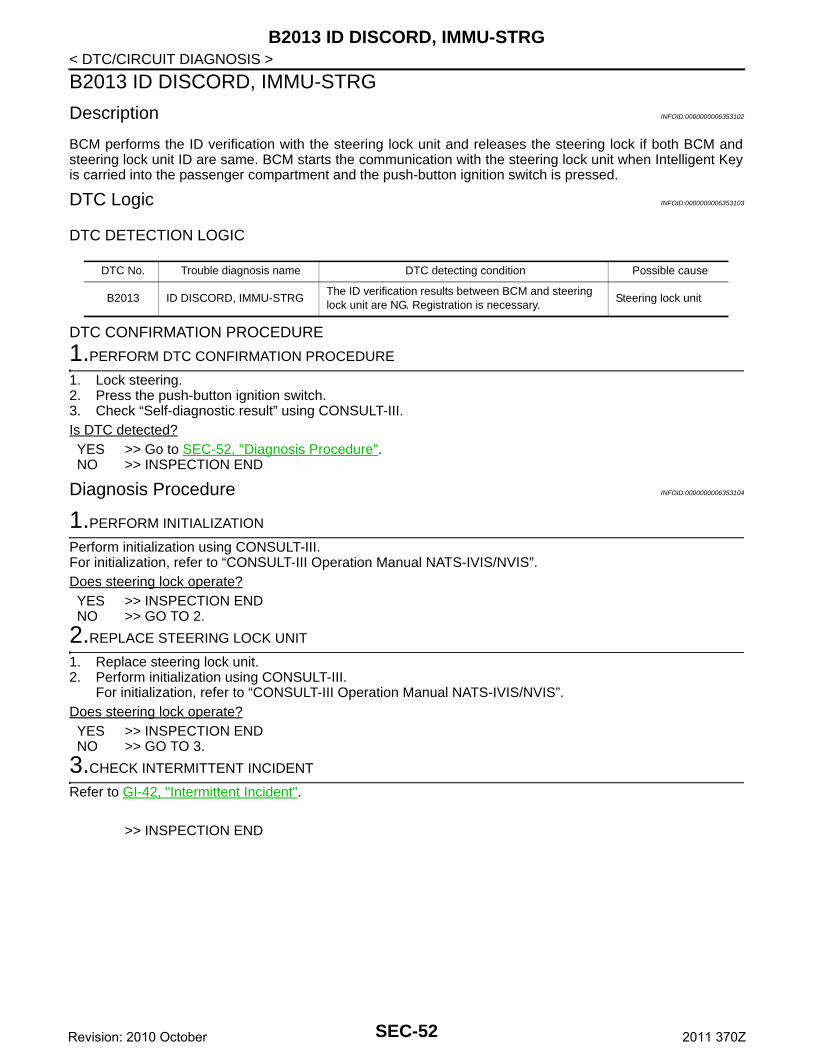
B2013 ID DISCORD, IMMU-STRG
< DTC/CIRCUIT DIAGNOSIS >B2013 ID DISCORD, IMMU-STRG
Description INFOID:0000000006353102
BCM performs the ID verification with the steering lock unit and releases the steering lock if both BCM andsteering lock unit ID are same. BCM starts the communication with the steering lock unit when Intelligent Keyis carried into the passenger compartment and the push-button ignition switch is pressed.
DTC Logic INFOID:0000000006353103
DTC DETECTION LOGIC
DTC CONFIRMATION PROCEDURE
1.PERFORM DTC CONFIRMATION PROCEDURE
1. Lock steering.2. Press the push-button ignition switch.3. Check “Self-diagnostic result” using CONSULT-III.Is DTC detected?YES >> Go to SEC-52, "Diagnosis Procedure".NO >> INSPECTION END
Diagnosis Procedure INFOID:0000000006353104
1.PERFORM INITIALIZATION
Perform initialization using CONSULT-III.For initialization, refer to “CONSULT-III Operation Manual NATS-IVIS/NVIS”.Does steering lock operate?YES >> INSPECTION ENDNO >> GO TO 2.
2.REPLACE STEERING LOCK UNIT
1. Replace steering lock unit.2. Perform initialization using CONSULT-III.
For initialization, refer to “CONSULT-III Operation Manual NATS-IVIS/NVIS”.Does steering lock operate?YES >> INSPECTION ENDNO >> GO TO 3.
3.CHECK INTERMITTENT INCIDENT
Refer to GI-42, "Intermittent Incident".
>> INSPECTION END
DTC No. Trouble diagnosis name DTC detecting condition Possible cause
B2013 ID DISCORD, IMMU-STRGThe ID verification results between BCM and steering lock unit are NG. Registration is necessary.
Steering lock unit
SEC-52Revision: 2010 October 2011 370Z
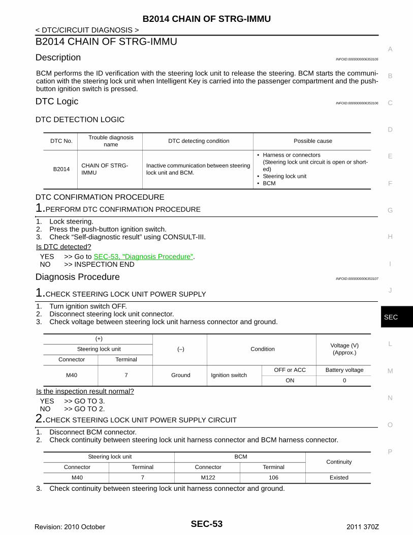
B2014 CHAIN OF STRG-IMMU
C
D
E
F
G
H
I
J
L
M
A
B
EC
N
O
P
< DTC/CIRCUIT DIAGNOSIS >
S
B2014 CHAIN OF STRG-IMMU
Description INFOID:0000000006353105
BCM performs the ID verification with the steering lock unit to release the steering. BCM starts the communi-cation with the steering lock unit when Intelligent Key is carried into the passenger compartment and the push-button ignition switch is pressed.
DTC Logic INFOID:0000000006353106
DTC DETECTION LOGIC
DTC CONFIRMATION PROCEDURE
1.PERFORM DTC CONFIRMATION PROCEDURE
1. Lock steering.2. Press the push-button ignition switch.3. Check “Self-diagnostic result” using CONSULT-III.Is DTC detected?YES >> Go to SEC-53, "Diagnosis Procedure".NO >> INSPECTION END
Diagnosis Procedure INFOID:0000000006353107
1.CHECK STEERING LOCK UNIT POWER SUPPLY
1. Turn ignition switch OFF.2. Disconnect steering lock unit connector.3. Check voltage between steering lock unit harness connector and ground.
Is the inspection result normal?YES >> GO TO 3.NO >> GO TO 2.
2.CHECK STEERING LOCK UNIT POWER SUPPLY CIRCUIT
1. Disconnect BCM connector.2. Check continuity between steering lock unit harness connector and BCM harness connector.
3. Check continuity between steering lock unit harness connector and ground.
DTC No.Trouble diagnosis
nameDTC detecting condition Possible cause
B2014CHAIN OF STRG-IMMU
Inactive communication between steering lock unit and BCM.
• Harness or connectors(Steering lock unit circuit is open or short-ed)
• Steering lock unit• BCM
(+)
(–) ConditionVoltage (V)(Approx.)
Steering lock unit
Connector Terminal
M40 7 Ground Ignition switchOFF or ACC Battery voltage
ON 0
Steering lock unit BCMContinuity
Connector Terminal Connector Terminal
M40 7 M122 106 Existed
SEC-53Revision: 2010 October 2011 370Z
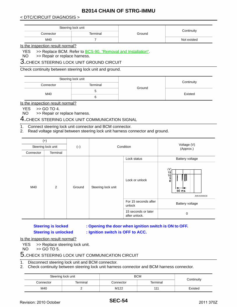
B2014 CHAIN OF STRG-IMMU
< DTC/CIRCUIT DIAGNOSIS >Is the inspection result normal?YES >> Replace BCM. Refer to BCS-90, "Removal and Installation".NO >> Repair or replace harness.
3.CHECK STEERING LOCK UNIT GROUND CIRCUIT
Check continuity between steering lock unit and ground.
Is the inspection result normal?YES >> GO TO 4.NO >> Repair or replace harness.
4.CHECK STEERING LOCK UNIT COMMUNICATION SIGNAL
1. Connect steering lock unit connector and BCM connector.2. Read voltage signal between steering lock unit harness connector and ground.
Is the inspection result normal?YES >> Replace steering lock unit.NO >> GO TO 5.
5.CHECK STEERING LOCK UNIT COMMUNICATION CIRCUIT
1. Disconnect steering lock unit and BCM connector.2. Check continuity between steering lock unit harness connector and BCM harness connector.
Steering lock unit
GroundContinuity
Connector Terminal
M40 7 Not existed
Steering lock unit
Ground
ContinuityConnector Terminal
M405
Existed6
(+)
(–) ConditionVoltage (V)(Approx.)
Steering lock unit
Connector Terminal
M40 2 Ground Steering lock unit
Lock status Battery voltage
Lock or unlock
For 15 seconds after unlock
Battery voltage
15 seconds or later after unlock.
0
Steering is locked : Opening the door when ignition switch is ON to OFF.Steering is unlocked : Ignition switch is OFF to ACC.
JMKIA0066GB
Steering lock unit BCMContinuity
Connector Terminal Connector Terminal
M40 2 M122 111 Existed
SEC-54Revision: 2010 October 2011 370Z
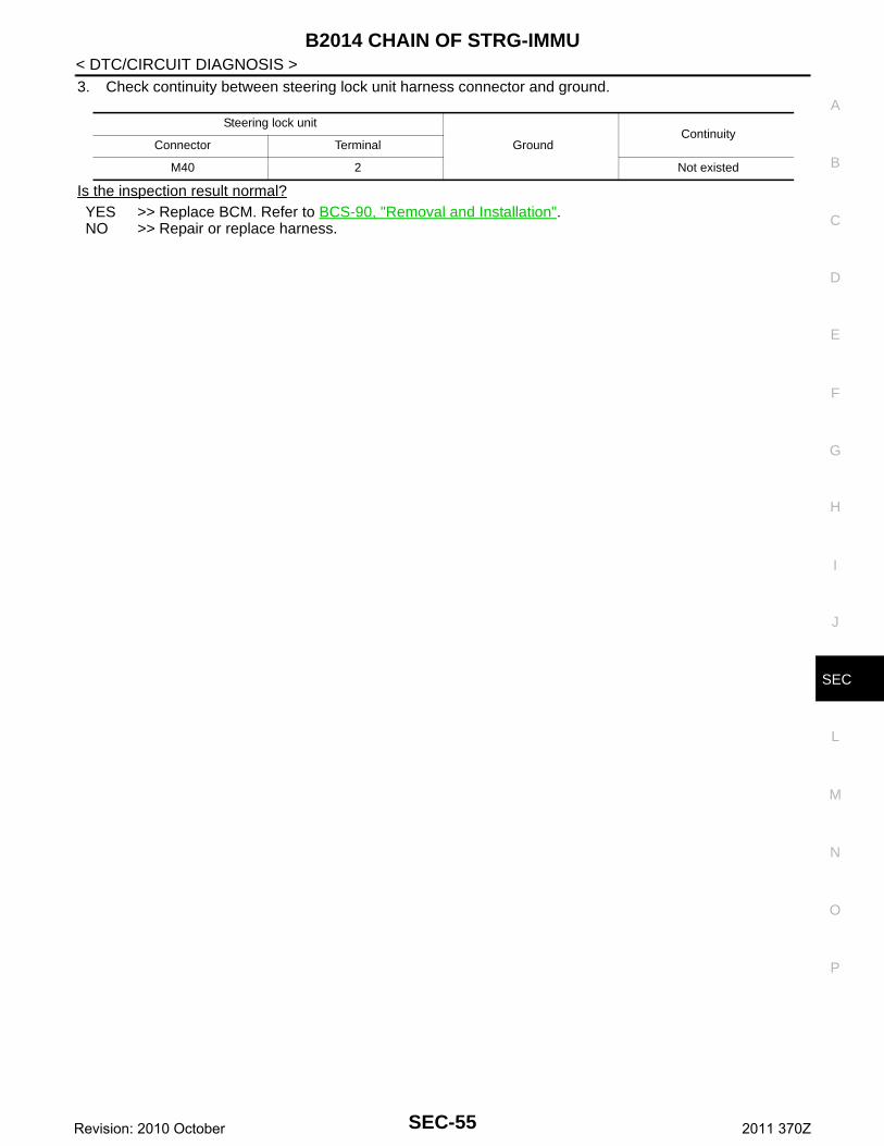
B2014 CHAIN OF STRG-IMMU
C
D
E
F
G
H
I
J
L
M
A
B
EC
N
O
P
< DTC/CIRCUIT DIAGNOSIS >
S
3. Check continuity between steering lock unit harness connector and ground.
Is the inspection result normal?YES >> Replace BCM. Refer to BCS-90, "Removal and Installation".NO >> Repair or replace harness.
Steering lock unit
GroundContinuity
Connector Terminal
M40 2 Not existed
SEC-55Revision: 2010 October 2011 370Z
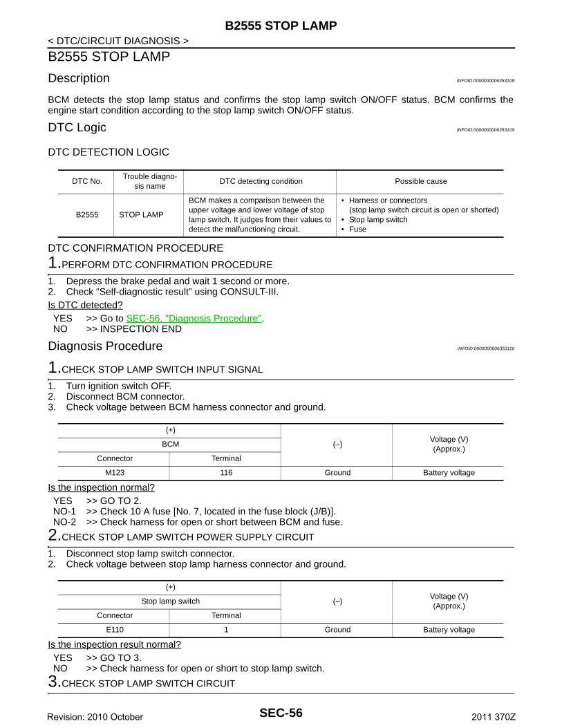
B2555 STOP LAMP
< DTC/CIRCUIT DIAGNOSIS >B2555 STOP LAMP
Description INFOID:0000000006353108
BCM detects the stop lamp status and confirms the stop lamp switch ON/OFF status. BCM confirms theengine start condition according to the stop lamp switch ON/OFF status.
DTC Logic INFOID:0000000006353109
DTC DETECTION LOGIC
DTC CONFIRMATION PROCEDURE
1.PERFORM DTC CONFIRMATION PROCEDURE
1. Depress the brake pedal and wait 1 second or more.2. Check “Self-diagnostic result” using CONSULT-III.Is DTC detected?YES >> Go to SEC-56, "Diagnosis Procedure".NO >> INSPECTION END
Diagnosis Procedure INFOID:0000000006353110
1.CHECK STOP LAMP SWITCH INPUT SIGNAL
1. Turn ignition switch OFF.2. Disconnect BCM connector.3. Check voltage between BCM harness connector and ground.
Is the inspection normal?YES >> GO TO 2.NO-1 >> Check 10 A fuse [No. 7, located in the fuse block (J/B)].NO-2 >> Check harness for open or short between BCM and fuse.
2.CHECK STOP LAMP SWITCH POWER SUPPLY CIRCUIT
1. Disconnect stop lamp switch connector.2. Check voltage between stop lamp harness connector and ground.
Is the inspection result normal?YES >> GO TO 3.NO >> Check harness for open or short to stop lamp switch.
3.CHECK STOP LAMP SWITCH CIRCUIT
DTC No.Trouble diagno-
sis nameDTC detecting condition Possible cause
B2555 STOP LAMP
BCM makes a comparison between the upper voltage and lower voltage of stop lamp switch. It judges from their values to detect the malfunctioning circuit.
• Harness or connectors(stop lamp switch circuit is open or shorted)
• Stop lamp switch• Fuse
(+)
(–)Voltage (V)(Approx.)
BCM
Connector Terminal
M123 116 Ground Battery voltage
(+)
(–)Voltage (V)(Approx.)
Stop lamp switch
Connector Terminal
E110 1 Ground Battery voltage
SEC-56Revision: 2010 October 2011 370Z
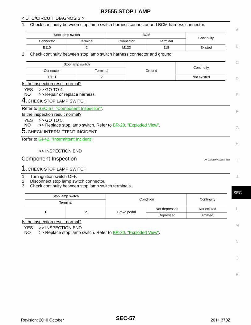
B2555 STOP LAMP
C
D
E
F
G
H
I
J
L
M
A
B
EC
N
O
P
< DTC/CIRCUIT DIAGNOSIS >
S
1. Check continuity between stop lamp switch harness connector and BCM harness connector.
2. Check continuity between stop lamp switch harness connector and ground.
Is the inspection result normal?YES >> GO TO 4.NO >> Repair or replace harness.
4.CHECK STOP LAMP SWITCH
Refer to SEC-57, "Component Inspection".Is the inspection result normal?YES >> GO TO 5.NO >> Replace stop lamp switch. Refer to BR-20, "Exploded View".
5.CHECK INTERMITTENT INCIDENT
Refer to GI-42, "Intermittent Incident".
>> INSPECTION END
Component Inspection INFOID:0000000006353111
1.CHECK STOP LAMP SWITCH
1. Turn ignition switch OFF.2. Disconnect stop lamp switch connector.3. Check continuity between stop lamp switch terminals.
Is the inspection result normal?YES >> INSPECTION ENDNO >> Replace stop lamp switch. Refer to BR-20, "Exploded View".
Stop lamp switch BCMContinuity
Connector Terminal Connector Terminal
E110 2 M123 118 Existed
Stop lamp switch
GroundContinuity
Connector Terminal
E110 2 Not existed
Stop lamp switchCondition Continuity
Terminal
1 2 Brake pedalNot depressed Not existed
Depressed Existed
SEC-57Revision: 2010 October 2011 370Z
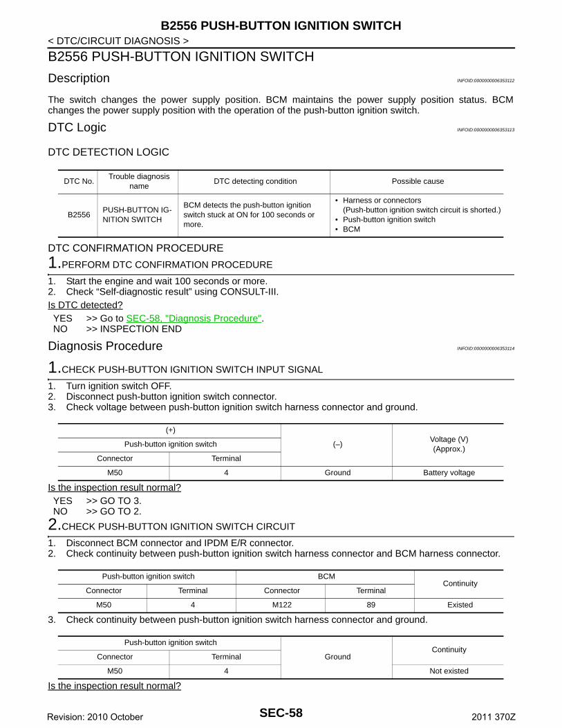
B2556 PUSH-BUTTON IGNITION SWITCH
< DTC/CIRCUIT DIAGNOSIS >B2556 PUSH-BUTTON IGNITION SWITCH
Description INFOID:0000000006353112
The switch changes the power supply position. BCM maintains the power supply position status. BCMchanges the power supply position with the operation of the push-button ignition switch.
DTC Logic INFOID:0000000006353113
DTC DETECTION LOGIC
DTC CONFIRMATION PROCEDURE
1.PERFORM DTC CONFIRMATION PROCEDURE
1. Start the engine and wait 100 seconds or more.2. Check “Self-diagnostic result” using CONSULT-III.Is DTC detected?YES >> Go to SEC-58, "Diagnosis Procedure".NO >> INSPECTION END
Diagnosis Procedure INFOID:0000000006353114
1.CHECK PUSH-BUTTON IGNITION SWITCH INPUT SIGNAL
1. Turn ignition switch OFF.2. Disconnect push-button ignition switch connector.3. Check voltage between push-button ignition switch harness connector and ground.
Is the inspection result normal?YES >> GO TO 3.NO >> GO TO 2.
2.CHECK PUSH-BUTTON IGNITION SWITCH CIRCUIT
1. Disconnect BCM connector and IPDM E/R connector.2. Check continuity between push-button ignition switch harness connector and BCM harness connector.
3. Check continuity between push-button ignition switch harness connector and ground.
Is the inspection result normal?
DTC No.Trouble diagnosis
nameDTC detecting condition Possible cause
B2556PUSH-BUTTON IG-NITION SWITCH
BCM detects the push-button ignition switch stuck at ON for 100 seconds or more.
• Harness or connectors(Push-button ignition switch circuit is shorted.)
• Push-button ignition switch• BCM
(+)
(–)Voltage (V)(Approx.)
Push-button ignition switch
Connector Terminal
M50 4 Ground Battery voltage
Push-button ignition switch BCMContinuity
Connector Terminal Connector Terminal
M50 4 M122 89 Existed
Push-button ignition switch
GroundContinuity
Connector Terminal
M50 4 Not existed
SEC-58Revision: 2010 October 2011 370Z
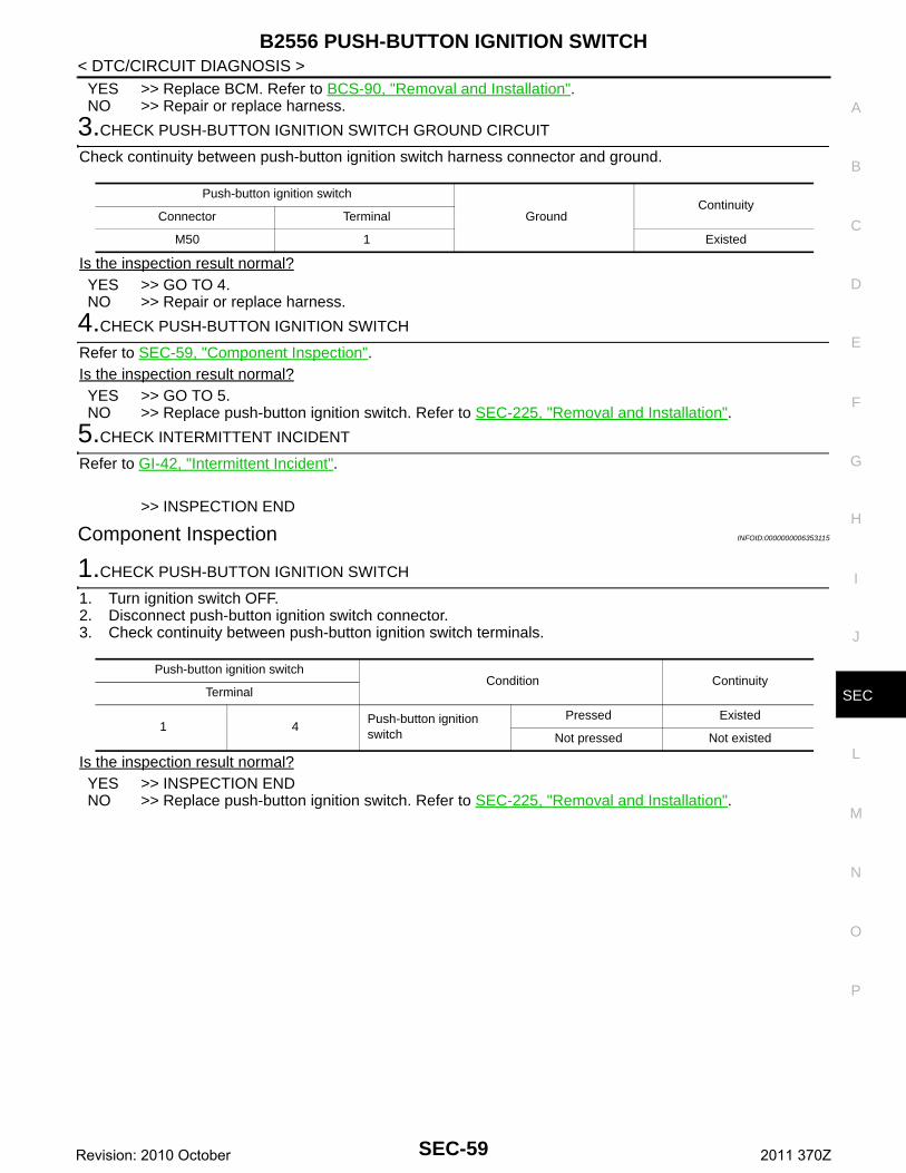
B2556 PUSH-BUTTON IGNITION SWITCH
C
D
E
F
G
H
I
J
L
M
A
B
EC
N
O
P
< DTC/CIRCUIT DIAGNOSIS >
S
YES >> Replace BCM. Refer to BCS-90, "Removal and Installation".NO >> Repair or replace harness.
3.CHECK PUSH-BUTTON IGNITION SWITCH GROUND CIRCUIT
Check continuity between push-button ignition switch harness connector and ground.
Is the inspection result normal?YES >> GO TO 4.NO >> Repair or replace harness.
4.CHECK PUSH-BUTTON IGNITION SWITCH
Refer to SEC-59, "Component Inspection".Is the inspection result normal?YES >> GO TO 5.NO >> Replace push-button ignition switch. Refer to SEC-225, "Removal and Installation".
5.CHECK INTERMITTENT INCIDENT
Refer to GI-42, "Intermittent Incident".
>> INSPECTION END
Component Inspection INFOID:0000000006353115
1.CHECK PUSH-BUTTON IGNITION SWITCH
1. Turn ignition switch OFF.2. Disconnect push-button ignition switch connector.3. Check continuity between push-button ignition switch terminals.
Is the inspection result normal?YES >> INSPECTION ENDNO >> Replace push-button ignition switch. Refer to SEC-225, "Removal and Installation".
Push-button ignition switch
GroundContinuity
Connector Terminal
M50 1 Existed
Push-button ignition switchCondition Continuity
Terminal
1 4Push-button ignition switch
Pressed Existed
Not pressed Not existed
SEC-59Revision: 2010 October 2011 370Z
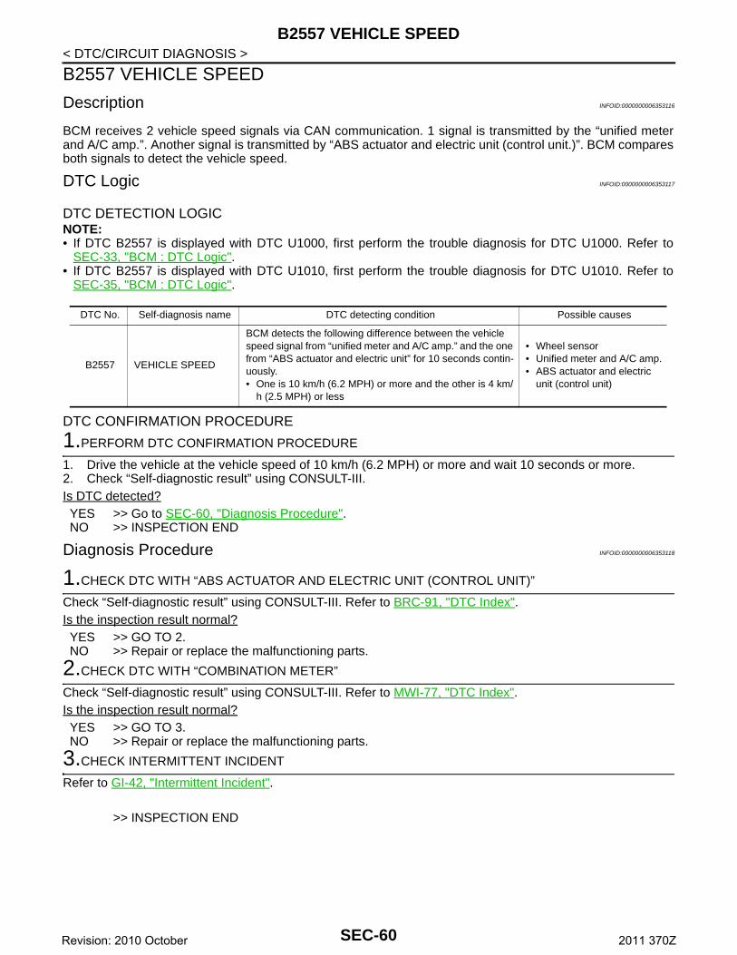
B2557 VEHICLE SPEED
< DTC/CIRCUIT DIAGNOSIS >B2557 VEHICLE SPEED
Description INFOID:0000000006353116
BCM receives 2 vehicle speed signals via CAN communication. 1 signal is transmitted by the “unified meterand A/C amp.”. Another signal is transmitted by “ABS actuator and electric unit (control unit.)”. BCM comparesboth signals to detect the vehicle speed.
DTC Logic INFOID:0000000006353117
DTC DETECTION LOGICNOTE:• If DTC B2557 is displayed with DTC U1000, first perform the trouble diagnosis for DTC U1000. Refer to
SEC-33, "BCM : DTC Logic".• If DTC B2557 is displayed with DTC U1010, first perform the trouble diagnosis for DTC U1010. Refer to
SEC-35, "BCM : DTC Logic".
DTC CONFIRMATION PROCEDURE
1.PERFORM DTC CONFIRMATION PROCEDURE
1. Drive the vehicle at the vehicle speed of 10 km/h (6.2 MPH) or more and wait 10 seconds or more.2. Check “Self-diagnostic result” using CONSULT-III.Is DTC detected?YES >> Go to SEC-60, "Diagnosis Procedure".NO >> INSPECTION END
Diagnosis Procedure INFOID:0000000006353118
1.CHECK DTC WITH “ABS ACTUATOR AND ELECTRIC UNIT (CONTROL UNIT)”
Check “Self-diagnostic result” using CONSULT-III. Refer to BRC-91, "DTC Index".Is the inspection result normal?YES >> GO TO 2.NO >> Repair or replace the malfunctioning parts.
2.CHECK DTC WITH “COMBINATION METER”
Check “Self-diagnostic result” using CONSULT-III. Refer to MWI-77, "DTC Index".Is the inspection result normal?YES >> GO TO 3.NO >> Repair or replace the malfunctioning parts.
3.CHECK INTERMITTENT INCIDENT
Refer to GI-42, "Intermittent Incident".
>> INSPECTION END
DTC No. Self-diagnosis name DTC detecting condition Possible causes
B2557 VEHICLE SPEED
BCM detects the following difference between the vehicle speed signal from “unified meter and A/C amp.” and the one from “ABS actuator and electric unit” for 10 seconds contin-uously.• One is 10 km/h (6.2 MPH) or more and the other is 4 km/
h (2.5 MPH) or less
• Wheel sensor• Unified meter and A/C amp.• ABS actuator and electric
unit (control unit)
SEC-60Revision: 2010 October 2011 370Z
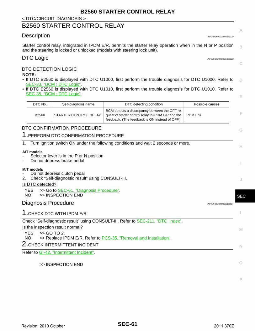
B2560 STARTER CONTROL RELAY
C
D
E
F
G
H
I
J
L
M
A
B
EC
N
O
P
< DTC/CIRCUIT DIAGNOSIS >
S
B2560 STARTER CONTROL RELAY
Description INFOID:0000000006353119
Starter control relay, integrated in IPDM E/R, permits the starter relay operation when in the N or P positionand the steering is locked or unlocked (models with steering lock unit).
DTC Logic INFOID:0000000006353120
DTC DETECTION LOGICNOTE:• If DTC B2560 is displayed with DTC U1000, first perform the trouble diagnosis for DTC U1000. Refer to
SEC-33, "BCM : DTC Logic".• If DTC B2560 is displayed with DTC U1010, first perform the trouble diagnosis for DTC U1010. Refer to
SEC-35, "BCM : DTC Logic".
DTC CONFIRMATION PROCEDURE
1.PERFORM DTC CONFIRMATION PROCEDURE
1. Turn ignition switch ON under the following conditions and wait 2 seconds or more.
A/T models- Selector lever is in the P or N position- Do not depress brake pedal
M/T models- Do not depress clutch pedal2. Check “Self-diagnostic result” using CONSULT-III.Is DTC detected?YES >> Go to SEC-61, "Diagnosis Procedure".NO >> INSPECTION END
Diagnosis Procedure INFOID:0000000006353121
1.CHECK DTC WITH IPDM E/R
Check “Self-diagnostic result” using CONSULT-III. Refer to SEC-211, "DTC Index".Is the inspection result normal?YES >> GO TO 2.NO >> Replace IPDM E/R. Refer to PCS-35, "Removal and Installation".
2.CHECK INTERMITTENT INCIDENT
Refer to GI-42, "Intermittent Incident".
>> INSPECTION END
DTC No. Self-diagnosis name DTC detecting condition Possible causes
B2560 STARTER CONTROL RELAYBCM detects a discrepancy between the OFF re-quest of starter control relay to IPDM E/R and the feedback. (The feedback is ON instead of OFF.)
IPDM E/R
SEC-61Revision: 2010 October 2011 370Z
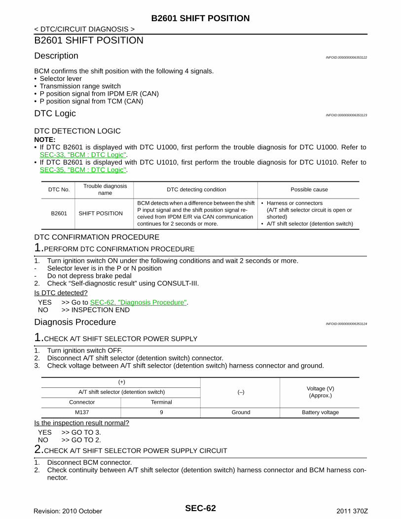
B2601 SHIFT POSITION
< DTC/CIRCUIT DIAGNOSIS >B2601 SHIFT POSITION
Description INFOID:0000000006353122
BCM confirms the shift position with the following 4 signals.• Selector lever• Transmission range switch• P position signal from IPDM E/R (CAN)• P position signal from TCM (CAN)
DTC Logic INFOID:0000000006353123
DTC DETECTION LOGICNOTE:• If DTC B2601 is displayed with DTC U1000, first perform the trouble diagnosis for DTC U1000. Refer to
SEC-33, "BCM : DTC Logic".• If DTC B2601 is displayed with DTC U1010, first perform the trouble diagnosis for DTC U1010. Refer to
SEC-35, "BCM : DTC Logic".
DTC CONFIRMATION PROCEDURE
1.PERFORM DTC CONFIRMATION PROCEDURE
1. Turn ignition switch ON under the following conditions and wait 2 seconds or more.- Selector lever is in the P or N position- Do not depress brake pedal2. Check “Self-diagnostic result” using CONSULT-III.Is DTC detected?YES >> Go to SEC-62, "Diagnosis Procedure".NO >> INSPECTION END
Diagnosis Procedure INFOID:0000000006353124
1.CHECK A/T SHIFT SELECTOR POWER SUPPLY
1. Turn ignition switch OFF.2. Disconnect A/T shift selector (detention switch) connector.3. Check voltage between A/T shift selector (detention switch) harness connector and ground.
Is the inspection result normal?YES >> GO TO 3.NO >> GO TO 2.
2.CHECK A/T SHIFT SELECTOR POWER SUPPLY CIRCUIT
1. Disconnect BCM connector.2. Check continuity between A/T shift selector (detention switch) harness connector and BCM harness con-
nector.
DTC No.Trouble diagnosis
nameDTC detecting condition Possible cause
B2601 SHIFT POSITION
BCM detects when a difference between the shift P input signal and the shift position signal re-ceived from IPDM E/R via CAN communication continues for 2 seconds or more.
• Harness or connectors(A/T shift selector circuit is open or shorted)
• A/T shift selector (detention switch)
(+)
(–)Voltage (V)(Approx.)
A/T shift selector (detention switch)
Connector Terminal
M137 9 Ground Battery voltage
SEC-62Revision: 2010 October 2011 370Z
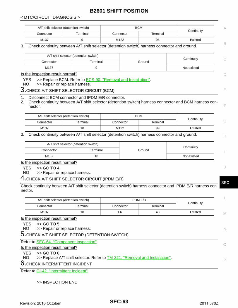
B2601 SHIFT POSITION
C
D
E
F
G
H
I
J
L
M
A
B
EC
N
O
P
< DTC/CIRCUIT DIAGNOSIS >
S
3. Check continuity between A/T shift selector (detention switch) harness connector and ground.
Is the inspection result normal?YES >> Replace BCM. Refer to BCS-90, "Removal and Installation".NO >> Repair or replace harness.
3.CHECK A/T SHIFT SELECTOR CIRCUIT (BCM)
1. Disconnect BCM connector and IPDM E/R connector.2. Check continuity between A/T shift selector (detention switch) harness connector and BCM harness con-
nector.
3. Check continuity between A/T shift selector (detention switch) harness connector and ground.
Is the inspection result normal?YES >> GO TO 4.NO >> Repair or replace harness.
4.CHECK A/T SHIFT SELECTOR CIRCUIT (IPDM E/R)
Check continuity between A/T shift selector (detention switch) harness connector and IPDM E/R harness con-nector.
Is the inspection result normal?YES >> GO TO 5.NO >> Repair or replace harness.
5.CHECK A/T SHIFT SELECTOR (DETENTION SWITCH)
Refer to SEC-64, "Component Inspection".Is the inspection result normal?YES >> GO TO 6.NO >> Replace A/T shift selector. Refer to TM-321, "Removal and Installation".
6.CHECK INTERMITTENT INCIDENT
Refer to GI-42, "Intermittent Incident".
>> INSPECTION END
A/T shift selector (detention switch) BCMContinuity
Connector Terminal Connector Terminal
M137 9 M122 96 Existed
A/T shift selector (detention switch)
GroundContinuity
Connector Terminal
M137 9 Not existed
A/T shift selector (detention switch) BCMContinuity
Connector Terminal Connector Terminal
M137 10 M122 99 Existed
A/T shift selector (detention switch)
GroundContinuity
Connector Terminal
M137 10 Not existed
A/T shift selector (detention switch) IPDM E/RContinuity
Connector Terminal Connector Terminal
M137 10 E6 43 Existed
SEC-63Revision: 2010 October 2011 370Z
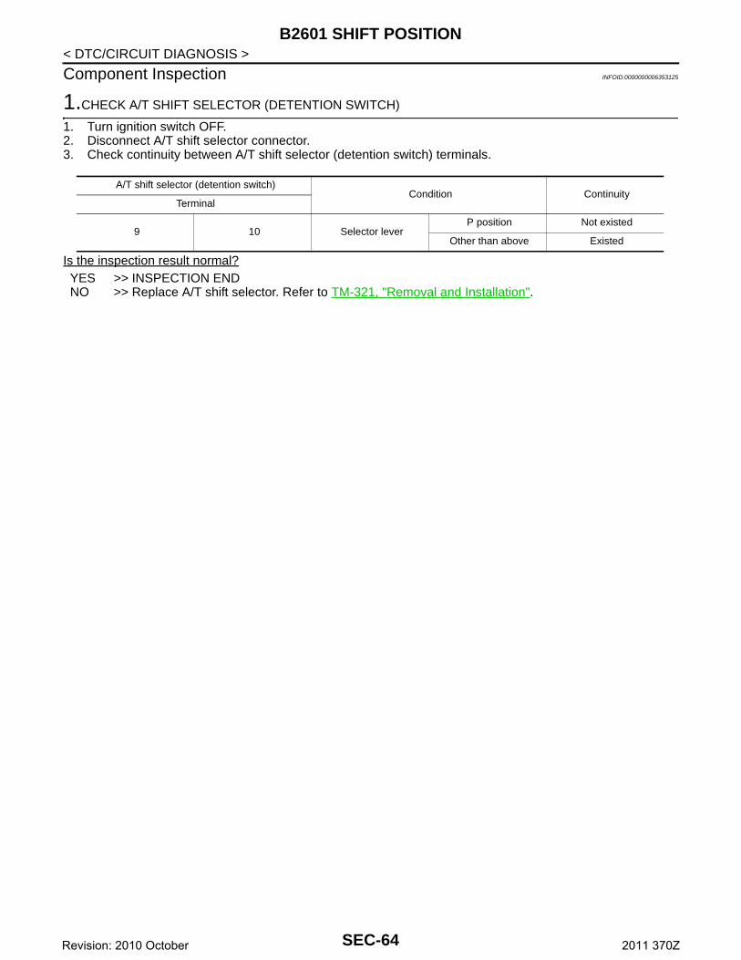
B2601 SHIFT POSITION
< DTC/CIRCUIT DIAGNOSIS >Component Inspection INFOID:0000000006353125
1.CHECK A/T SHIFT SELECTOR (DETENTION SWITCH)
1. Turn ignition switch OFF.2. Disconnect A/T shift selector connector.3. Check continuity between A/T shift selector (detention switch) terminals.
Is the inspection result normal?YES >> INSPECTION ENDNO >> Replace A/T shift selector. Refer to TM-321, "Removal and Installation".
A/T shift selector (detention switch)Condition Continuity
Terminal
9 10 Selector leverP position Not existed
Other than above Existed
SEC-64Revision: 2010 October 2011 370Z
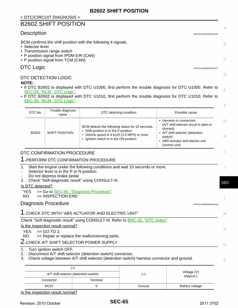
B2602 SHIFT POSITION
C
D
E
F
G
H
I
J
L
M
A
B
EC
N
O
P
< DTC/CIRCUIT DIAGNOSIS >
S
B2602 SHIFT POSITION
Description INFOID:0000000006353126
BCM confirms the shift position with the following 4 signals.• Selector lever• Transmission range switch• P position signal from IPDM E/R (CAN)• P position signal from TCM (CAN)
DTC Logic INFOID:0000000006353127
DTC DETECTION LOGICNOTE:• If DTC B2602 is displayed with DTC U1000, first perform the trouble diagnosis for DTC U1000. Refer to
SEC-33, "BCM : DTC Logic".• If DTC B2602 is displayed with DTC U1010, first perform the trouble diagnosis for DTC U1010. Refer to
SEC-35, "BCM : DTC Logic".
DTC CONFIRMATION PROCEDURE
1.PERFORM DTC CONFIRMATION PROCEDURE
1. Start the engine under the following conditions and wait 10 seconds or more.- Selector lever is in the P or N position- Do not depress brake pedal2. Check “Self-diagnostic result” using CONSULT-III.Is DTC detected?YES >> Go to SEC-65, "Diagnosis Procedure".NO >> INSPECTION END
Diagnosis Procedure INFOID:0000000006353128
1.CHECK DTC WITH “ABS ACTUATOR AND ELECTRIC UNIT”
Check “Self-diagnostic result” using CONSULT-III. Refer to BRC-91, "DTC Index".Is the inspection result normal?YES >> GO TO 2.NO >> Repair or replace the malfunctioning parts.
2.CHECK A/T SHIFT SELECTOR POWER SUPPLY
1. Turn ignition switch OFF.2. Disconnect A/T shift selector (detention switch) connector.3. Check voltage between A/T shift selector (detention switch) harness connector and ground.
Is the inspection result normal?
DTC No.Trouble diagnosis
nameDTC detecting condition Possible cause
B2602 SHIFT POSITION
BCM detects the following status for 10 seconds.• Shift position is in the P position• Vehicle speed is 4 km/h (2.5 MPH) or more• Ignition switch is in the ON position
• Harness or connectors (A/T shift selector circuit is open or shorted)
• A/T shift selector (detention switch)
• ABS actuator and electric unit (control unit)
(+)
(–)Voltage (V)(Approx.)
A/T shift selector (detention switch)
Connector Terminal
M137 9 Ground Battery voltage
SEC-65Revision: 2010 October 2011 370Z
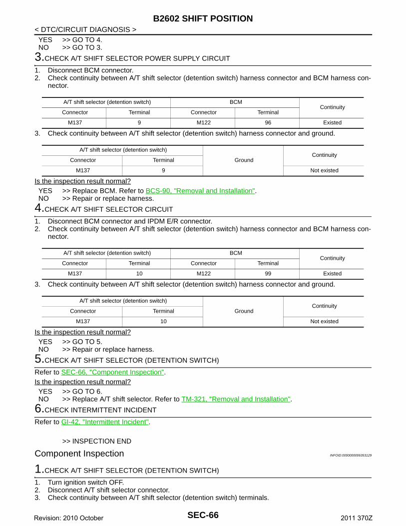
B2602 SHIFT POSITION
< DTC/CIRCUIT DIAGNOSIS >YES >> GO TO 4.NO >> GO TO 3.3.CHECK A/T SHIFT SELECTOR POWER SUPPLY CIRCUIT
1. Disconnect BCM connector.2. Check continuity between A/T shift selector (detention switch) harness connector and BCM harness con-
nector.
3. Check continuity between A/T shift selector (detention switch) harness connector and ground.
Is the inspection result normal?YES >> Replace BCM. Refer to BCS-90, "Removal and Installation".NO >> Repair or replace harness.
4.CHECK A/T SHIFT SELECTOR CIRCUIT
1. Disconnect BCM connector and IPDM E/R connector.2. Check continuity between A/T shift selector (detention switch) harness connector and BCM harness con-
nector.
3. Check continuity between A/T shift selector (detention switch) harness connector and ground.
Is the inspection result normal?YES >> GO TO 5.NO >> Repair or replace harness.
5.CHECK A/T SHIFT SELECTOR (DETENTION SWITCH)
Refer to SEC-66, "Component Inspection".Is the inspection result normal?YES >> GO TO 6.NO >> Replace A/T shift selector. Refer to TM-321, "Removal and Installation".
6.CHECK INTERMITTENT INCIDENT
Refer to GI-42, "Intermittent Incident".
>> INSPECTION END
Component Inspection INFOID:0000000006353129
1.CHECK A/T SHIFT SELECTOR (DETENTION SWITCH)
1. Turn ignition switch OFF.2. Disconnect A/T shift selector connector.3. Check continuity between A/T shift selector (detention switch) terminals.
A/T shift selector (detention switch) BCMContinuity
Connector Terminal Connector Terminal
M137 9 M122 96 Existed
A/T shift selector (detention switch)
GroundContinuity
Connector Terminal
M137 9 Not existed
A/T shift selector (detention switch) BCMContinuity
Connector Terminal Connector Terminal
M137 10 M122 99 Existed
A/T shift selector (detention switch)
GroundContinuity
Connector Terminal
M137 10 Not existed
SEC-66Revision: 2010 October 2011 370Z
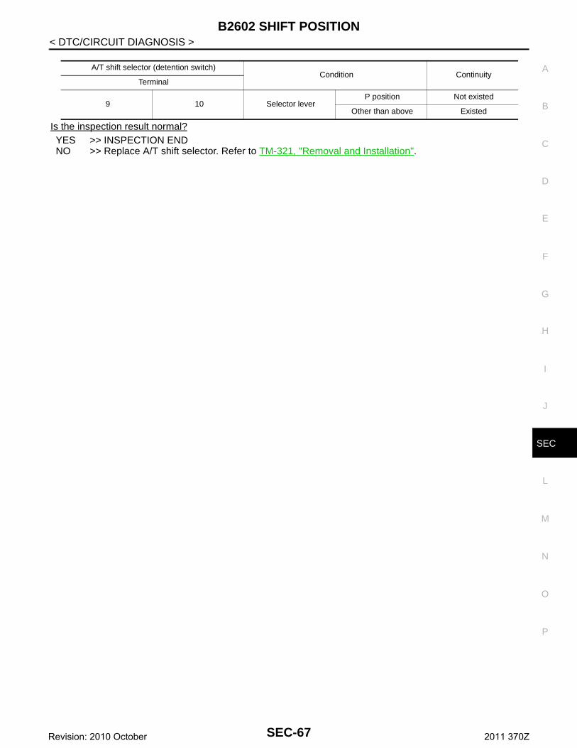
B2602 SHIFT POSITION
C
D
E
F
G
H
I
J
L
M
A
B
EC
N
O
P
< DTC/CIRCUIT DIAGNOSIS >
S
Is the inspection result normal?YES >> INSPECTION ENDNO >> Replace A/T shift selector. Refer to TM-321, "Removal and Installation".
A/T shift selector (detention switch)Condition Continuity
Terminal
9 10 Selector leverP position Not existed
Other than above Existed
SEC-67Revision: 2010 October 2011 370Z
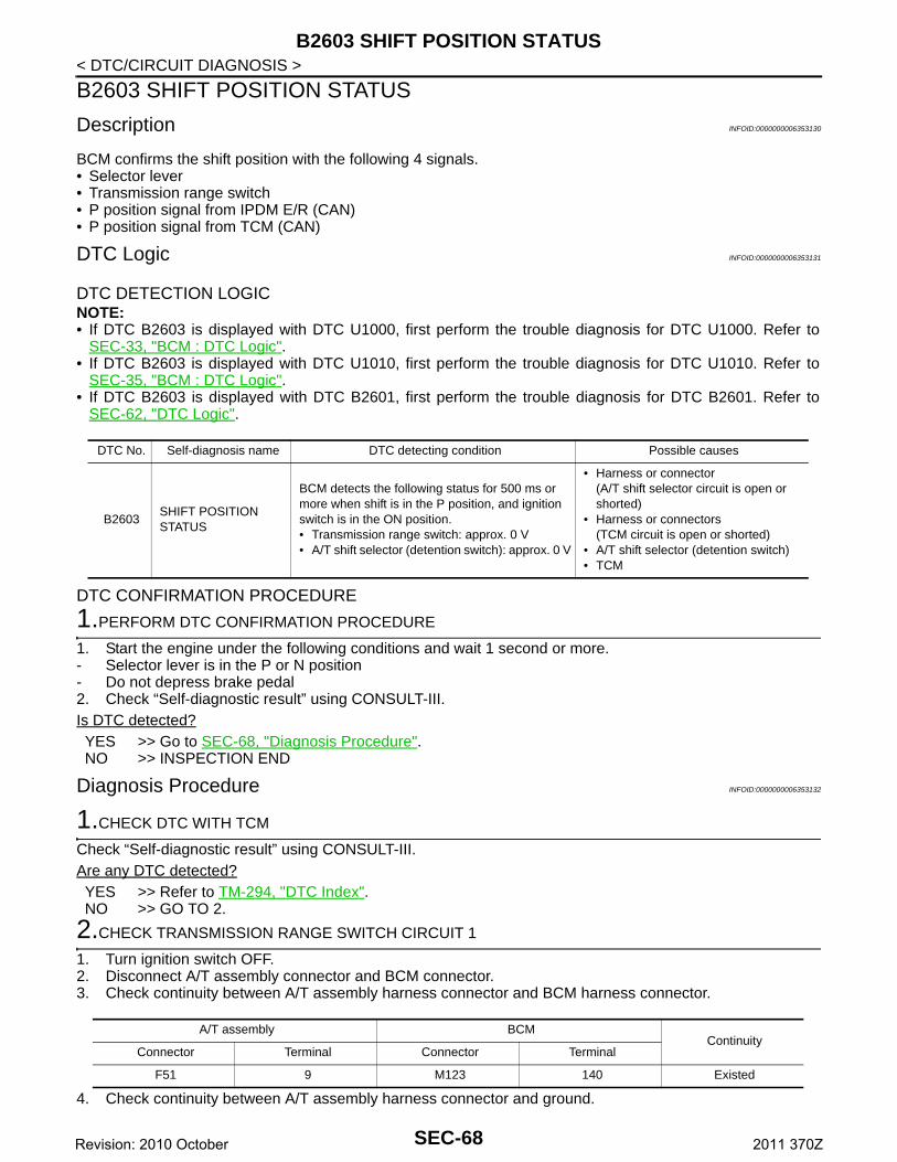
B2603 SHIFT POSITION STATUS
< DTC/CIRCUIT DIAGNOSIS >B2603 SHIFT POSITION STATUS
Description INFOID:0000000006353130
BCM confirms the shift position with the following 4 signals.• Selector lever• Transmission range switch• P position signal from IPDM E/R (CAN)• P position signal from TCM (CAN)
DTC Logic INFOID:0000000006353131
DTC DETECTION LOGICNOTE:• If DTC B2603 is displayed with DTC U1000, first perform the trouble diagnosis for DTC U1000. Refer to
SEC-33, "BCM : DTC Logic".• If DTC B2603 is displayed with DTC U1010, first perform the trouble diagnosis for DTC U1010. Refer to
SEC-35, "BCM : DTC Logic".• If DTC B2603 is displayed with DTC B2601, first perform the trouble diagnosis for DTC B2601. Refer to
SEC-62, "DTC Logic".
DTC CONFIRMATION PROCEDURE
1.PERFORM DTC CONFIRMATION PROCEDURE
1. Start the engine under the following conditions and wait 1 second or more.- Selector lever is in the P or N position- Do not depress brake pedal2. Check “Self-diagnostic result” using CONSULT-III.Is DTC detected?YES >> Go to SEC-68, "Diagnosis Procedure".NO >> INSPECTION END
Diagnosis Procedure INFOID:0000000006353132
1.CHECK DTC WITH TCM
Check “Self-diagnostic result” using CONSULT-III.Are any DTC detected?YES >> Refer to TM-294, "DTC Index".NO >> GO TO 2.
2.CHECK TRANSMISSION RANGE SWITCH CIRCUIT 1
1. Turn ignition switch OFF.2. Disconnect A/T assembly connector and BCM connector.3. Check continuity between A/T assembly harness connector and BCM harness connector.
4. Check continuity between A/T assembly harness connector and ground.
DTC No. Self-diagnosis name DTC detecting condition Possible causes
B2603SHIFT POSITION STATUS
BCM detects the following status for 500 ms or more when shift is in the P position, and ignition switch is in the ON position.• Transmission range switch: approx. 0 V• A/T shift selector (detention switch): approx. 0 V
• Harness or connector(A/T shift selector circuit is open or shorted)
• Harness or connectors(TCM circuit is open or shorted)
• A/T shift selector (detention switch)• TCM
A/T assembly BCMContinuity
Connector Terminal Connector Terminal
F51 9 M123 140 Existed
SEC-68Revision: 2010 October 2011 370Z
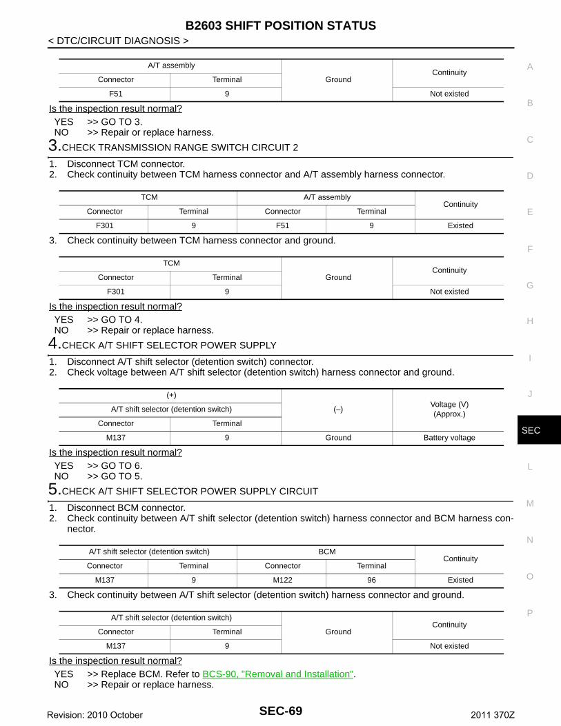
B2603 SHIFT POSITION STATUS
C
D
E
F
G
H
I
J
L
M
A
B
EC
N
O
P
< DTC/CIRCUIT DIAGNOSIS >
S
Is the inspection result normal?YES >> GO TO 3.NO >> Repair or replace harness.
3.CHECK TRANSMISSION RANGE SWITCH CIRCUIT 2
1. Disconnect TCM connector.2. Check continuity between TCM harness connector and A/T assembly harness connector.
3. Check continuity between TCM harness connector and ground.
Is the inspection result normal?YES >> GO TO 4.NO >> Repair or replace harness.
4.CHECK A/T SHIFT SELECTOR POWER SUPPLY
1. Disconnect A/T shift selector (detention switch) connector.2. Check voltage between A/T shift selector (detention switch) harness connector and ground.
Is the inspection result normal?YES >> GO TO 6.NO >> GO TO 5.
5.CHECK A/T SHIFT SELECTOR POWER SUPPLY CIRCUIT
1. Disconnect BCM connector.2. Check continuity between A/T shift selector (detention switch) harness connector and BCM harness con-
nector.
3. Check continuity between A/T shift selector (detention switch) harness connector and ground.
Is the inspection result normal?YES >> Replace BCM. Refer to BCS-90, "Removal and Installation".NO >> Repair or replace harness.
A/T assembly
GroundContinuity
Connector Terminal
F51 9 Not existed
TCM A/T assemblyContinuity
Connector Terminal Connector Terminal
F301 9 F51 9 Existed
TCM
GroundContinuity
Connector Terminal
F301 9 Not existed
(+)
(–)Voltage (V)(Approx.)
A/T shift selector (detention switch)
Connector Terminal
M137 9 Ground Battery voltage
A/T shift selector (detention switch) BCMContinuity
Connector Terminal Connector Terminal
M137 9 M122 96 Existed
A/T shift selector (detention switch)
GroundContinuity
Connector Terminal
M137 9 Not existed
SEC-69Revision: 2010 October 2011 370Z
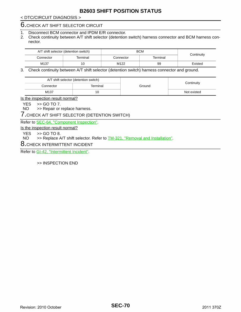
B2603 SHIFT POSITION STATUS
< DTC/CIRCUIT DIAGNOSIS >6.CHECK A/T SHIFT SELECTOR CIRCUIT
1. Disconnect BCM connector and IPDM E/R connector.2. Check continuity between A/T shift selector (detention switch) harness connector and BCM harness con-
nector.
3. Check continuity between A/T shift selector (detention switch) harness connector and ground.
Is the inspection result normal?YES >> GO TO 7.NO >> Repair or replace harness.
7.CHECK A/T SHIFT SELECTOR (DETENTION SWITCH)
Refer to SEC-64, "Component Inspection".Is the inspection result normal?YES >> GO TO 8.NO >> Replace A/T shift selector. Refer to TM-321, "Removal and Installation".
8.CHECK INTERMITTENT INCIDENT
Refer to GI-42, "Intermittent Incident".
>> INSPECTION END
A/T shift selector (detention switch) BCMContinuity
Connector Terminal Connector Terminal
M137 10 M122 99 Existed
A/T shift selector (detention switch)
GroundContinuity
Connector Terminal
M137 10 Not existed
SEC-70Revision: 2010 October 2011 370Z
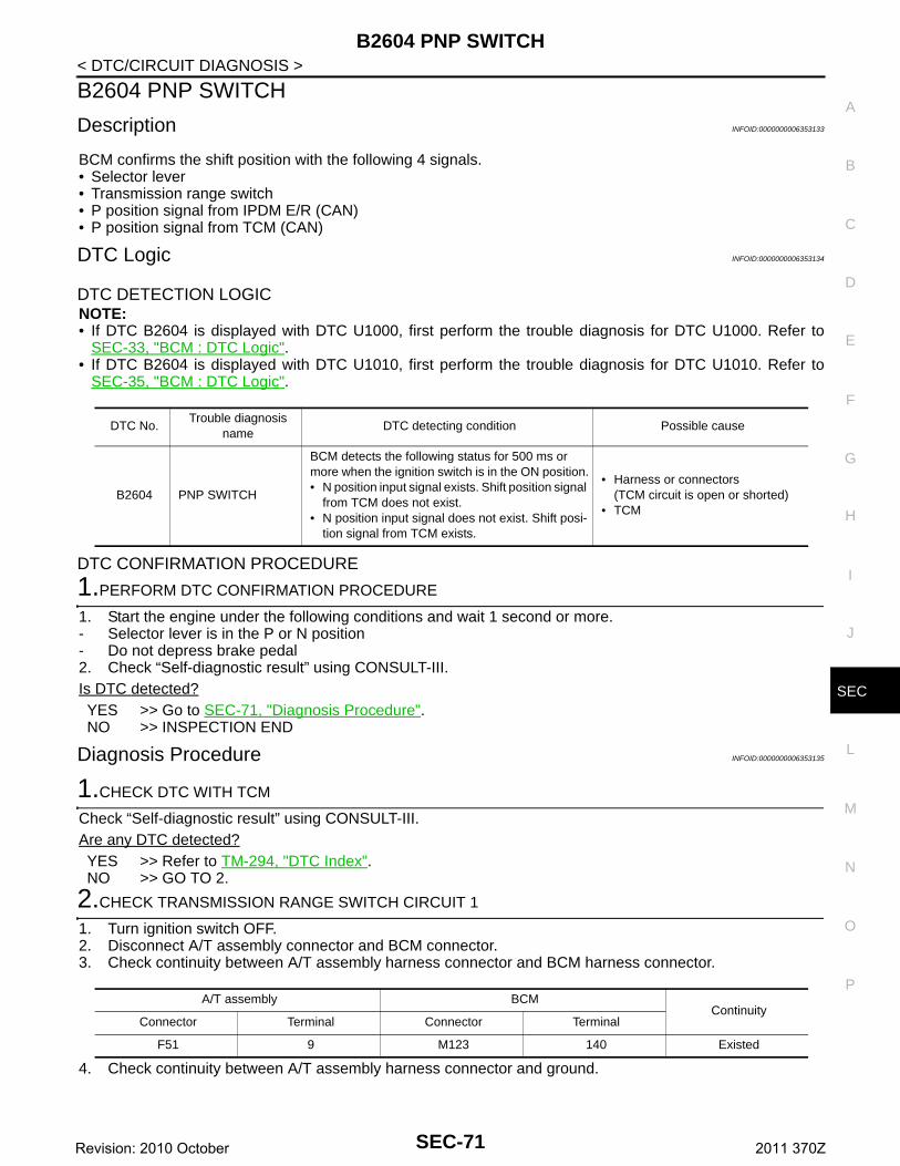
B2604 PNP SWITCH
C
D
E
F
G
H
I
J
L
M
A
B
EC
N
O
P
< DTC/CIRCUIT DIAGNOSIS >
S
B2604 PNP SWITCH
Description INFOID:0000000006353133
BCM confirms the shift position with the following 4 signals.• Selector lever• Transmission range switch• P position signal from IPDM E/R (CAN)• P position signal from TCM (CAN)
DTC Logic INFOID:0000000006353134
DTC DETECTION LOGICNOTE:• If DTC B2604 is displayed with DTC U1000, first perform the trouble diagnosis for DTC U1000. Refer to
SEC-33, "BCM : DTC Logic".• If DTC B2604 is displayed with DTC U1010, first perform the trouble diagnosis for DTC U1010. Refer to
SEC-35, "BCM : DTC Logic".
DTC CONFIRMATION PROCEDURE
1.PERFORM DTC CONFIRMATION PROCEDURE
1. Start the engine under the following conditions and wait 1 second or more.- Selector lever is in the P or N position- Do not depress brake pedal2. Check “Self-diagnostic result” using CONSULT-III.Is DTC detected?YES >> Go to SEC-71, "Diagnosis Procedure".NO >> INSPECTION END
Diagnosis Procedure INFOID:0000000006353135
1.CHECK DTC WITH TCM
Check “Self-diagnostic result” using CONSULT-III.Are any DTC detected?YES >> Refer to TM-294, "DTC Index".NO >> GO TO 2.
2.CHECK TRANSMISSION RANGE SWITCH CIRCUIT 1
1. Turn ignition switch OFF.2. Disconnect A/T assembly connector and BCM connector.3. Check continuity between A/T assembly harness connector and BCM harness connector.
4. Check continuity between A/T assembly harness connector and ground.
DTC No.Trouble diagnosis
nameDTC detecting condition Possible cause
B2604 PNP SWITCH
BCM detects the following status for 500 ms or more when the ignition switch is in the ON position.• N position input signal exists. Shift position signal
from TCM does not exist.• N position input signal does not exist. Shift posi-
tion signal from TCM exists.
• Harness or connectors (TCM circuit is open or shorted)
• TCM
A/T assembly BCMContinuity
Connector Terminal Connector Terminal
F51 9 M123 140 Existed
SEC-71Revision: 2010 October 2011 370Z
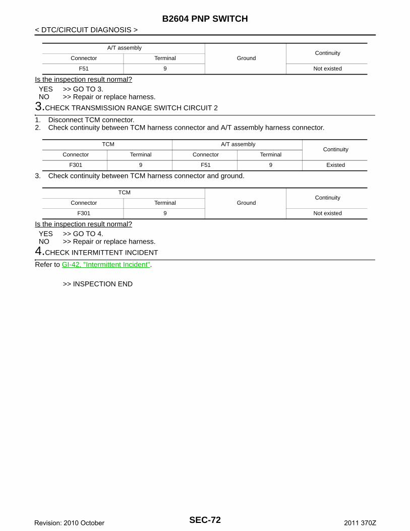
B2604 PNP SWITCH
< DTC/CIRCUIT DIAGNOSIS >Is the inspection result normal?YES >> GO TO 3.NO >> Repair or replace harness.
3.CHECK TRANSMISSION RANGE SWITCH CIRCUIT 2
1. Disconnect TCM connector.2. Check continuity between TCM harness connector and A/T assembly harness connector.
3. Check continuity between TCM harness connector and ground.
Is the inspection result normal?YES >> GO TO 4.NO >> Repair or replace harness.
4.CHECK INTERMITTENT INCIDENT
Refer to GI-42, "Intermittent Incident".
>> INSPECTION END
A/T assembly
GroundContinuity
Connector Terminal
F51 9 Not existed
TCM A/T assemblyContinuity
Connector Terminal Connector Terminal
F301 9 F51 9 Existed
TCM
GroundContinuity
Connector Terminal
F301 9 Not existed
SEC-72Revision: 2010 October 2011 370Z
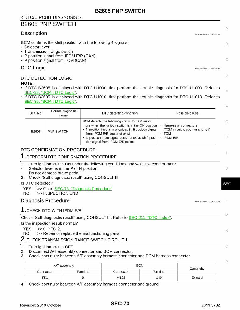
B2605 PNP SWITCH
C
D
E
F
G
H
I
J
L
M
A
B
EC
N
O
P
< DTC/CIRCUIT DIAGNOSIS >
S
B2605 PNP SWITCH
Description INFOID:0000000006353136
BCM confirms the shift position with the following 4 signals.• Selector lever• Transmission range switch• P position signal from IPDM E/R (CAN)• P position signal from TCM (CAN)
DTC Logic INFOID:0000000006353137
DTC DETECTION LOGICNOTE:• If DTC B2605 is displayed with DTC U1000, first perform the trouble diagnosis for DTC U1000. Refer to
SEC-33, "BCM : DTC Logic".• If DTC B2605 is displayed with DTC U1010, first perform the trouble diagnosis for DTC U1010. Refer to
SEC-35, "BCM : DTC Logic".
DTC CONFIRMATION PROCEDURE
1.PERFORM DTC CONFIRMATION PROCEDURE
1. Turn ignition switch ON under the following conditions and wait 1 second or more.- Selector lever is in the P or N position- Do not depress brake pedal2. Check “Self-diagnostic result” using CONSULT-III.Is DTC detected?YES >> Go to SEC-73, "Diagnosis Procedure".NO >> INSPECTION END
Diagnosis Procedure INFOID:0000000006353138
1.CHECK DTC WITH IPDM E/R
Check “Self-diagnostic result” using CONSULT-III. Refer to SEC-211, "DTC Index".Is the inspection result normal?YES >> GO TO 2.NO >> Repair or replace the malfunctioning parts.
2.CHECK TRANSMISSION RANGE SWITCH CIRCUIT 1
1. Turn ignition switch OFF.2. Disconnect A/T assembly connector and BCM connector.3. Check continuity between A/T assembly harness connector and BCM harness connector.
4. Check continuity between A/T assembly harness connector and ground.
DTC No.Trouble diagnosis
nameDTC detecting condition Possible cause
B2605 PNP SWITCH
BCM detects the following status for 500 ms or more when the ignition switch is in the ON position• N position input signal exists. Shift position signal
from IPDM E/R does not exist.• N position input signal does not exist. Shift posi-
tion signal from IPDM E/R exists.
• Harness or connectors(TCM circuit is open or shorted)
• TCM• IPDM E/R
A/T assembly BCMContinuity
Connector Terminal Connector Terminal
F51 9 M123 140 Existed
SEC-73Revision: 2010 October 2011 370Z

B2605 PNP SWITCH
< DTC/CIRCUIT DIAGNOSIS >Is the inspection result normal?YES >> GO TO 3.NO >> Repair or replace harness.
3.CHECK TRANSMISSION RANGE SWITCH CIRCUIT 2
1. Disconnect TCM connector.2. Check continuity between TCM harness connector and A/T assembly harness connector.
3. Check continuity between TCM harness connector and ground.
Is the inspection result normal?YES >> GO TO 4.NO >> Repair or replace harness.
4.CHECK INTERMITTENT INCIDENT
Refer to GI-42, "Intermittent Incident".
>> INSPECTION END
A/T assembly
GroundContinuity
Connector Terminal
F51 9 Not existed
TCM A/T assemblyContinuity
Connector Terminal Connector Terminal
F301 9 F51 9 Existed
TCM
GroundContinuity
Connector Terminal
F301 9 Not existed
SEC-74Revision: 2010 October 2011 370Z
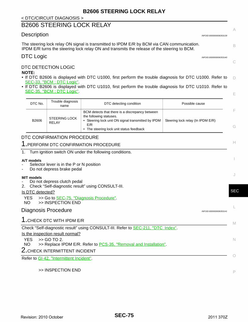
B2606 STEERING LOCK RELAY
C
D
E
F
G
H
I
J
L
M
A
B
EC
N
O
P
< DTC/CIRCUIT DIAGNOSIS >
S
B2606 STEERING LOCK RELAY
Description INFOID:0000000006353139
The steering lock relay ON signal is transmitted to IPDM E/R by BCM via CAN communication.IPDM E/R turns the steering lock relay ON and transmits the release of the steering to BCM.
DTC Logic INFOID:0000000006353140
DTC DETECTION LOGICNOTE:• If DTC B2606 is displayed with DTC U1000, first perform the trouble diagnosis for DTC U1000. Refer to
SEC-33, "BCM : DTC Logic".• If DTC B2606 is displayed with DTC U1010, first perform the trouble diagnosis for DTC U1010. Refer to
SEC-35, "BCM : DTC Logic".
DTC CONFIRMATION PROCEDURE
1.PERFORM DTC CONFIRMATION PROCEDURE
1. Turn ignition switch ON under the following conditions.
A/T models- Selector lever is in the P or N position- Do not depress brake pedal
M/T models- Do not depress clutch pedal2. Check “Self-diagnostic result” using CONSULT-III.Is DTC detected?YES >> Go to SEC-75, "Diagnosis Procedure".NO >> INSPECTION END
Diagnosis Procedure INFOID:0000000006353141
1.CHECK DTC WITH IPDM E/R
Check “Self-diagnostic result” using CONSULT-III. Refer to SEC-211, "DTC Index".Is the inspection result normal?YES >> GO TO 2.NO >> Replace IPDM E/R. Refer to PCS-35, "Removal and Installation".
2.CHECK INTERMITTENT INCIDENT
Refer to GI-42, "Intermittent Incident".
>> INSPECTION END
DTC No.Trouble diagnosis
nameDTC detecting condition Possible cause
B2606STEERING LOCK RELAY
BCM detects that there is a discrepancy between the following statuses.• Steering lock unit ON signal transmitted by IPDM
E/R• The steering lock unit status feedback
Steering lock relay (In IPDM E/R)
SEC-75Revision: 2010 October 2011 370Z
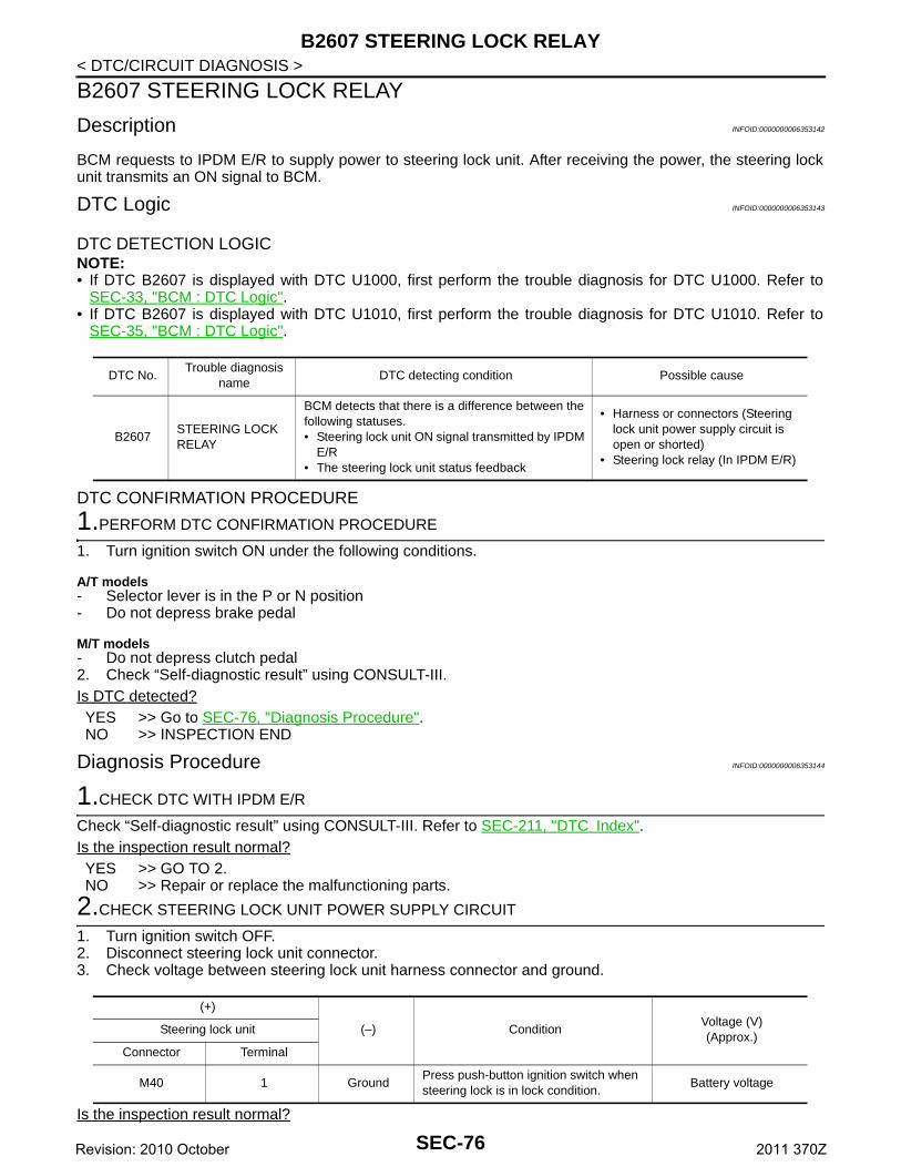
B2607 STEERING LOCK RELAY
< DTC/CIRCUIT DIAGNOSIS >B2607 STEERING LOCK RELAY
Description INFOID:0000000006353142
BCM requests to IPDM E/R to supply power to steering lock unit. After receiving the power, the steering lockunit transmits an ON signal to BCM.
DTC Logic INFOID:0000000006353143
DTC DETECTION LOGICNOTE:• If DTC B2607 is displayed with DTC U1000, first perform the trouble diagnosis for DTC U1000. Refer to
SEC-33, "BCM : DTC Logic".• If DTC B2607 is displayed with DTC U1010, first perform the trouble diagnosis for DTC U1010. Refer to
SEC-35, "BCM : DTC Logic".
DTC CONFIRMATION PROCEDURE
1.PERFORM DTC CONFIRMATION PROCEDURE
1. Turn ignition switch ON under the following conditions.
A/T models- Selector lever is in the P or N position- Do not depress brake pedal
M/T models- Do not depress clutch pedal2. Check “Self-diagnostic result” using CONSULT-III.Is DTC detected?YES >> Go to SEC-76, "Diagnosis Procedure".NO >> INSPECTION END
Diagnosis Procedure INFOID:0000000006353144
1.CHECK DTC WITH IPDM E/R
Check “Self-diagnostic result” using CONSULT-III. Refer to SEC-211, "DTC Index".Is the inspection result normal?YES >> GO TO 2.NO >> Repair or replace the malfunctioning parts.
2.CHECK STEERING LOCK UNIT POWER SUPPLY CIRCUIT
1. Turn ignition switch OFF.2. Disconnect steering lock unit connector.3. Check voltage between steering lock unit harness connector and ground.
Is the inspection result normal?
DTC No.Trouble diagnosis
nameDTC detecting condition Possible cause
B2607STEERING LOCK RELAY
BCM detects that there is a difference between the following statuses.• Steering lock unit ON signal transmitted by IPDM
E/R• The steering lock unit status feedback
• Harness or connectors (Steering lock unit power supply circuit is open or shorted)
• Steering lock relay (In IPDM E/R)
(+)
(–) ConditionVoltage (V)(Approx.)
Steering lock unit
Connector Terminal
M40 1 GroundPress push-button ignition switch when steering lock is in lock condition.
Battery voltage
SEC-76Revision: 2010 October 2011 370Z
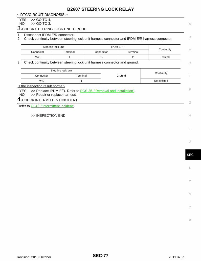
B2607 STEERING LOCK RELAY
C
D
E
F
G
H
I
J
L
M
A
B
EC
N
O
P
< DTC/CIRCUIT DIAGNOSIS >
S
YES >> GO TO 4.NO >> GO TO 3.
3.CHECK STEERING LOCK UNIT CIRCUIT
1. Disconnect IPDM E/R connector.2. Check continuity between steering lock unit harness connector and IPDM E/R harness connector.
3. Check continuity between steering lock unit harness connector and ground.
Is the inspection result normal?YES >> Replace IPDM E/R. Refer to PCS-35, "Removal and Installation".NO >> Repair or replace harness.
4.CHECK INTERMITTENT INCIDENT
Refer to GI-42, "Intermittent Incident".
>> INSPECTION END
Steering lock unit IPDM E/RContinuity
Connector Terminal Connector Terminal
M40 1 E5 11 Existed
Steering lock unit
GroundContinuity
Connector Terminal
M40 1 Not existed
SEC-77Revision: 2010 October 2011 370Z
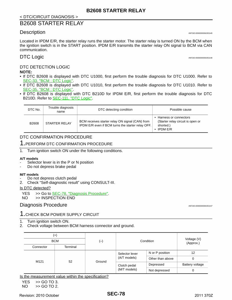
B2608 STARTER RELAY
< DTC/CIRCUIT DIAGNOSIS >B2608 STARTER RELAY
Description INFOID:0000000006353145
Located in IPDM E/R, the starter relay runs the starter motor. The starter relay is turned ON by the BCM whenthe ignition switch is in the START position. IPDM E/R transmits the starter relay ON signal to BCM via CANcommunication.
DTC Logic INFOID:0000000006353146
DTC DETECTION LOGICNOTE:• If DTC B2608 is displayed with DTC U1000, first perform the trouble diagnosis for DTC U1000. Refer to
SEC-33, "BCM : DTC Logic".• If DTC B2608 is displayed with DTC U1010, first perform the trouble diagnosis for DTC U1010. Refer to
SEC-35, "BCM : DTC Logic".• If DTC B2608 is displayed with DTC B210D for IPDM E/R, first perform the trouble diagnosis for DTC
B210D. Refer to SEC-111, "DTC Logic".
DTC CONFIRMATION PROCEDURE
1.PERFORM DTC CONFIRMATION PROCEDURE
1. Turn ignition switch ON under the following conditions.
A/T models- Selector lever is in the P or N position- Do not depress brake pedal
M/T models- Do not depress clutch pedal2. Check “Self-diagnostic result” using CONSULT-III.Is DTC detected?YES >> Go to SEC-78, "Diagnosis Procedure".NO >> INSPECTION END
Diagnosis Procedure INFOID:0000000006353147
1.CHECK BCM POWER SUPPLY CIRCUIT
1. Turn ignition switch ON.2. Check voltage between BCM harness connector and ground.
Is the measurement value within the specification?YES >> GO TO 3.NO >> GO TO 2.
DTC No.Trouble diagnosis
nameDTC detecting condition Possible cause
B2608 STARTER RELAYBCM receives starter relay ON signal (CAN) from IPDM E/R even if BCM turns the starter relay OFF.
• Harness or connectors (Starter relay circuit is open or shorted.)
• IPDM E/R
(+)
(–) ConditionVoltage (V)(Approx.)
BCM
Connector Terminal
M121 52 Ground
Selector lever(A/T models)
N or P position 12
Other than above 0
Clutch pedal(M/T models)
Depressed Battery voltage
Not depressed 0
SEC-78Revision: 2010 October 2011 370Z
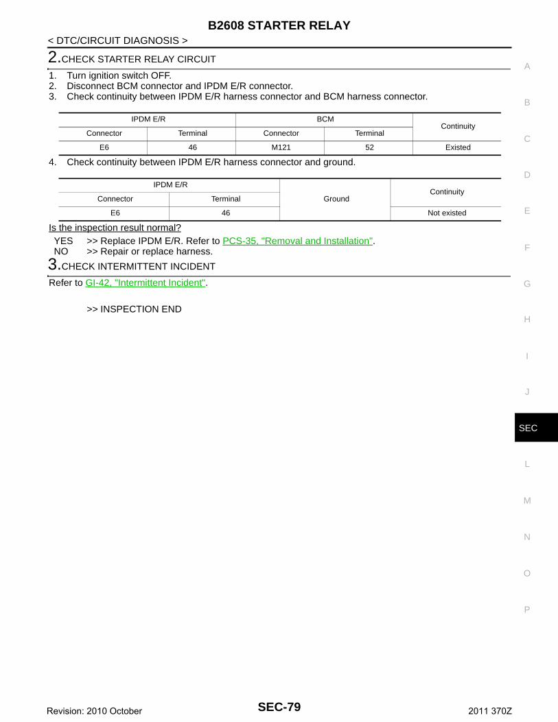
B2608 STARTER RELAY
C
D
E
F
G
H
I
J
L
M
A
B
EC
N
O
P
< DTC/CIRCUIT DIAGNOSIS >
S
2.CHECK STARTER RELAY CIRCUIT
1. Turn ignition switch OFF.2. Disconnect BCM connector and IPDM E/R connector.3. Check continuity between IPDM E/R harness connector and BCM harness connector.
4. Check continuity between IPDM E/R harness connector and ground.
Is the inspection result normal?YES >> Replace IPDM E/R. Refer to PCS-35, "Removal and Installation".NO >> Repair or replace harness.
3.CHECK INTERMITTENT INCIDENT
Refer to GI-42, "Intermittent Incident".
>> INSPECTION END
IPDM E/R BCMContinuity
Connector Terminal Connector Terminal
E6 46 M121 52 Existed
IPDM E/R
GroundContinuity
Connector Terminal
E6 46 Not existed
SEC-79Revision: 2010 October 2011 370Z
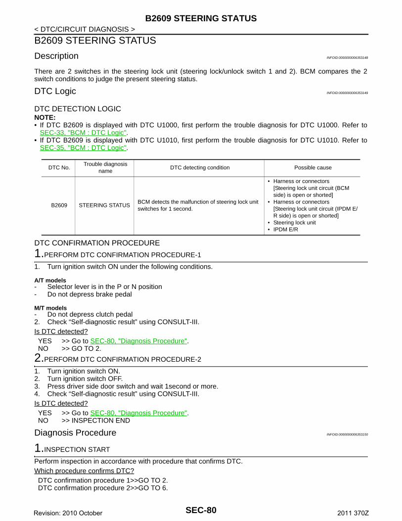
B2609 STEERING STATUS
< DTC/CIRCUIT DIAGNOSIS >B2609 STEERING STATUS
Description INFOID:0000000006353148
There are 2 switches in the steering lock unit (steering lock/unlock switch 1 and 2). BCM compares the 2switch conditions to judge the present steering status.
DTC Logic INFOID:0000000006353149
DTC DETECTION LOGICNOTE:• If DTC B2609 is displayed with DTC U1000, first perform the trouble diagnosis for DTC U1000. Refer to
SEC-33, "BCM : DTC Logic".• If DTC B2609 is displayed with DTC U1010, first perform the trouble diagnosis for DTC U1010. Refer to
SEC-35, "BCM : DTC Logic".
DTC CONFIRMATION PROCEDURE
1.PERFORM DTC CONFIRMATION PROCEDURE-1
1. Turn ignition switch ON under the following conditions.
A/T models- Selector lever is in the P or N position- Do not depress brake pedal
M/T models- Do not depress clutch pedal2. Check “Self-diagnostic result” using CONSULT-III.Is DTC detected?YES >> Go to SEC-80, "Diagnosis Procedure".NO >> GO TO 2.
2.PERFORM DTC CONFIRMATION PROCEDURE-2
1. Turn ignition switch ON.2. Turn ignition switch OFF.3. Press driver side door switch and wait 1second or more.4. Check “Self-diagnostic result” using CONSULT-III.Is DTC detected?YES >> Go to SEC-80, "Diagnosis Procedure".NO >> INSPECTION END
Diagnosis Procedure INFOID:0000000006353150
1.INSPECTION START
Perform inspection in accordance with procedure that confirms DTC.Which procedure confirms DTC?DTC confirmation procedure 1>>GO TO 2.DTC confirmation procedure 2>>GO TO 6.
DTC No.Trouble diagnosis
nameDTC detecting condition Possible cause
B2609 STEERING STATUSBCM detects the malfunction of steering lock unit switches for 1 second.
• Harness or connectors[Steering lock unit circuit (BCM side) is open or shorted]
• Harness or connectors[Steering lock unit circuit (IPDM E/R side) is open or shorted]
• Steering lock unit • IPDM E/R
SEC-80Revision: 2010 October 2011 370Z
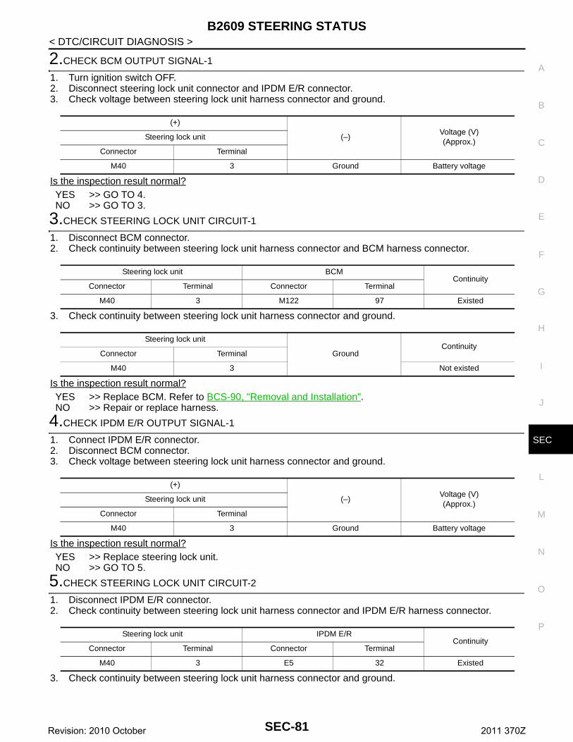
B2609 STEERING STATUS
C
D
E
F
G
H
I
J
L
M
A
B
EC
N
O
P
< DTC/CIRCUIT DIAGNOSIS >
S
2.CHECK BCM OUTPUT SIGNAL-1
1. Turn ignition switch OFF.2. Disconnect steering lock unit connector and IPDM E/R connector.3. Check voltage between steering lock unit harness connector and ground.
Is the inspection result normal?YES >> GO TO 4.NO >> GO TO 3.
3.CHECK STEERING LOCK UNIT CIRCUIT-1
1. Disconnect BCM connector.2. Check continuity between steering lock unit harness connector and BCM harness connector.
3. Check continuity between steering lock unit harness connector and ground.
Is the inspection result normal?YES >> Replace BCM. Refer to BCS-90, "Removal and Installation".NO >> Repair or replace harness.
4.CHECK IPDM E/R OUTPUT SIGNAL-1
1. Connect IPDM E/R connector.2. Disconnect BCM connector.3. Check voltage between steering lock unit harness connector and ground.
Is the inspection result normal?YES >> Replace steering lock unit.NO >> GO TO 5.
5.CHECK STEERING LOCK UNIT CIRCUIT-2
1. Disconnect IPDM E/R connector.2. Check continuity between steering lock unit harness connector and IPDM E/R harness connector.
3. Check continuity between steering lock unit harness connector and ground.
(+)
(–)Voltage (V)(Approx.)
Steering lock unit
Connector Terminal
M40 3 Ground Battery voltage
Steering lock unit BCMContinuity
Connector Terminal Connector Terminal
M40 3 M122 97 Existed
Steering lock unit
GroundContinuity
Connector Terminal
M40 3 Not existed
(+)
(–)Voltage (V)(Approx.)
Steering lock unit
Connector Terminal
M40 3 Ground Battery voltage
Steering lock unit IPDM E/RContinuity
Connector Terminal Connector Terminal
M40 3 E5 32 Existed
SEC-81Revision: 2010 October 2011 370Z
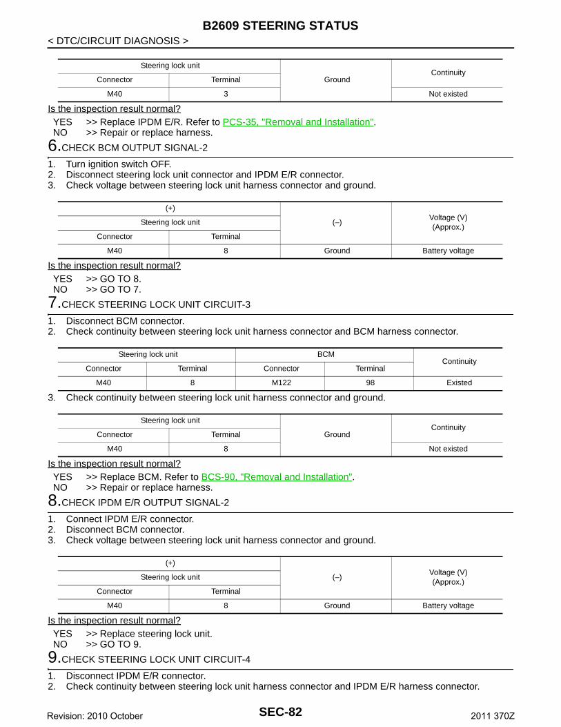
B2609 STEERING STATUS
< DTC/CIRCUIT DIAGNOSIS >Is the inspection result normal?YES >> Replace IPDM E/R. Refer to PCS-35, "Removal and Installation".NO >> Repair or replace harness.
6.CHECK BCM OUTPUT SIGNAL-2
1. Turn ignition switch OFF.2. Disconnect steering lock unit connector and IPDM E/R connector.3. Check voltage between steering lock unit harness connector and ground.
Is the inspection result normal?YES >> GO TO 8.NO >> GO TO 7.
7.CHECK STEERING LOCK UNIT CIRCUIT-3
1. Disconnect BCM connector.2. Check continuity between steering lock unit harness connector and BCM harness connector.
3. Check continuity between steering lock unit harness connector and ground.
Is the inspection result normal?YES >> Replace BCM. Refer to BCS-90, "Removal and Installation".NO >> Repair or replace harness.
8.CHECK IPDM E/R OUTPUT SIGNAL-2
1. Connect IPDM E/R connector.2. Disconnect BCM connector.3. Check voltage between steering lock unit harness connector and ground.
Is the inspection result normal?YES >> Replace steering lock unit.NO >> GO TO 9.
9.CHECK STEERING LOCK UNIT CIRCUIT-4
1. Disconnect IPDM E/R connector.2. Check continuity between steering lock unit harness connector and IPDM E/R harness connector.
Steering lock unit
GroundContinuity
Connector Terminal
M40 3 Not existed
(+)
(–)Voltage (V)(Approx.)
Steering lock unit
Connector Terminal
M40 8 Ground Battery voltage
Steering lock unit BCMContinuity
Connector Terminal Connector Terminal
M40 8 M122 98 Existed
Steering lock unit
GroundContinuity
Connector Terminal
M40 8 Not existed
(+)
(–)Voltage (V)(Approx.)
Steering lock unit
Connector Terminal
M40 8 Ground Battery voltage
SEC-82Revision: 2010 October 2011 370Z
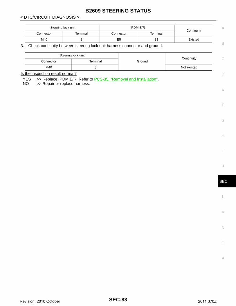
B2609 STEERING STATUS
C
D
E
F
G
H
I
J
L
M
A
B
EC
N
O
P
< DTC/CIRCUIT DIAGNOSIS >
S
3. Check continuity between steering lock unit harness connector and ground.
Is the inspection result normal?YES >> Replace IPDM E/R. Refer to PCS-35, "Removal and Installation".NO >> Repair or replace harness.
Steering lock unit IPDM E/RContinuity
Connector Terminal Connector Terminal
M40 8 E5 33 Existed
Steering lock unit
GroundContinuity
Connector Terminal
M40 8 Not existed
SEC-83Revision: 2010 October 2011 370Z
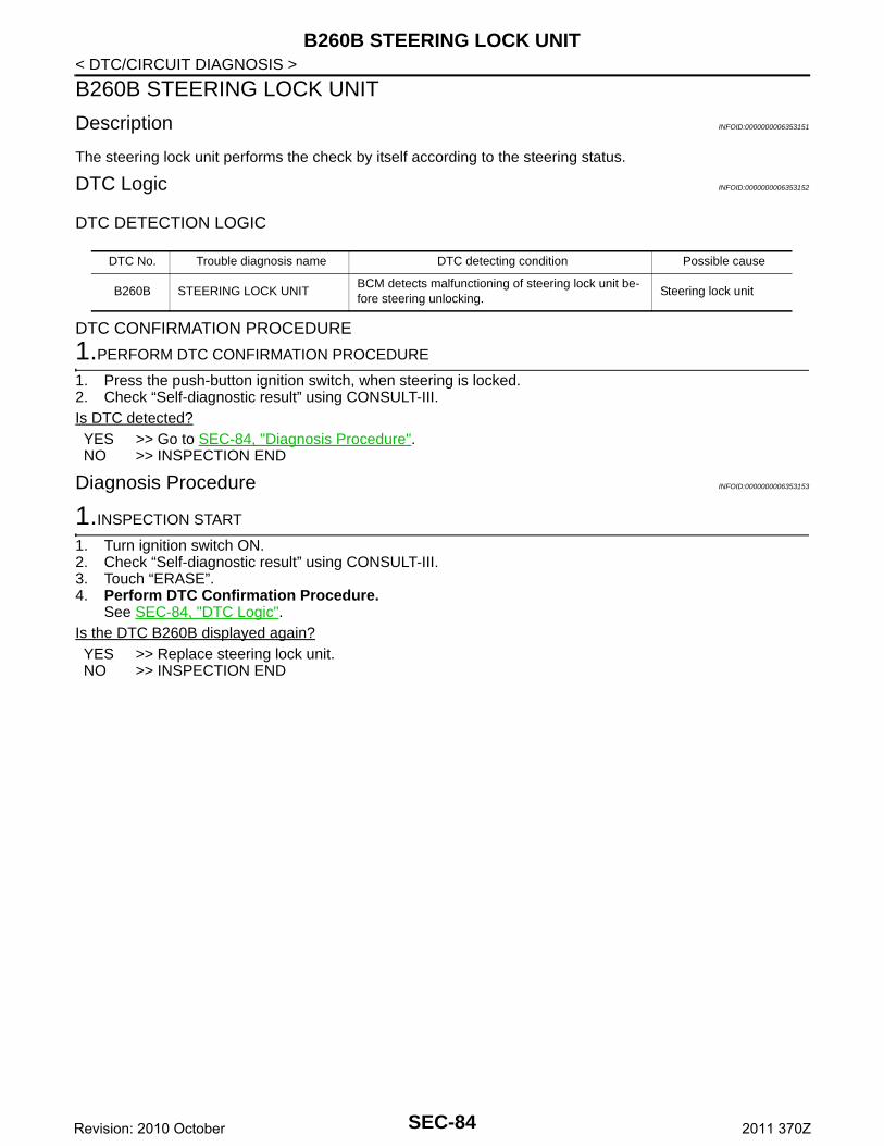
B260B STEERING LOCK UNIT
< DTC/CIRCUIT DIAGNOSIS >B260B STEERING LOCK UNIT
Description INFOID:0000000006353151
The steering lock unit performs the check by itself according to the steering status.
DTC Logic INFOID:0000000006353152
DTC DETECTION LOGIC
DTC CONFIRMATION PROCEDURE
1.PERFORM DTC CONFIRMATION PROCEDURE
1. Press the push-button ignition switch, when steering is locked.2. Check “Self-diagnostic result” using CONSULT-III.Is DTC detected?YES >> Go to SEC-84, "Diagnosis Procedure".NO >> INSPECTION END
Diagnosis Procedure INFOID:0000000006353153
1.INSPECTION START
1. Turn ignition switch ON.2. Check “Self-diagnostic result” using CONSULT-III.3. Touch “ERASE”.4. Perform DTC Confirmation Procedure.
See SEC-84, "DTC Logic".Is the DTC B260B displayed again?YES >> Replace steering lock unit. NO >> INSPECTION END
DTC No. Trouble diagnosis name DTC detecting condition Possible cause
B260B STEERING LOCK UNITBCM detects malfunctioning of steering lock unit be-fore steering unlocking.
Steering lock unit
SEC-84Revision: 2010 October 2011 370Z
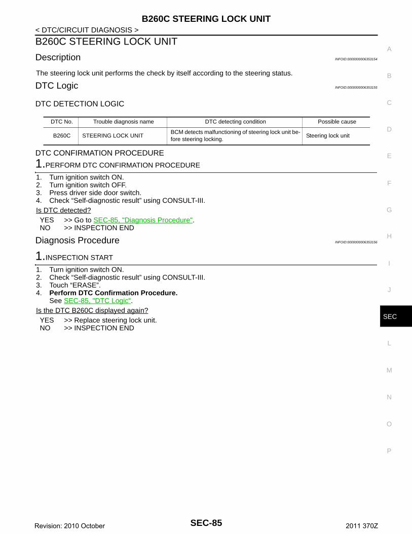
B260C STEERING LOCK UNIT
C
D
E
F
G
H
I
J
L
M
A
B
EC
N
O
P
< DTC/CIRCUIT DIAGNOSIS >
S
B260C STEERING LOCK UNIT
Description INFOID:0000000006353154
The steering lock unit performs the check by itself according to the steering status.
DTC Logic INFOID:0000000006353155
DTC DETECTION LOGIC
DTC CONFIRMATION PROCEDURE
1.PERFORM DTC CONFIRMATION PROCEDURE
1. Turn ignition switch ON.2. Turn ignition switch OFF.3. Press driver side door switch.4. Check “Self-diagnostic result” using CONSULT-III.Is DTC detected?YES >> Go to SEC-85, "Diagnosis Procedure".NO >> INSPECTION END
Diagnosis Procedure INFOID:0000000006353156
1.INSPECTION START
1. Turn ignition switch ON.2. Check “Self-diagnostic result” using CONSULT-III.3. Touch “ERASE”.4. Perform DTC Confirmation Procedure.
See SEC-85, "DTC Logic".Is the DTC B260C displayed again?YES >> Replace steering lock unit.NO >> INSPECTION END
DTC No. Trouble diagnosis name DTC detecting condition Possible cause
B260C STEERING LOCK UNITBCM detects malfunctioning of steering lock unit be-fore steering locking.
Steering lock unit
SEC-85Revision: 2010 October 2011 370Z
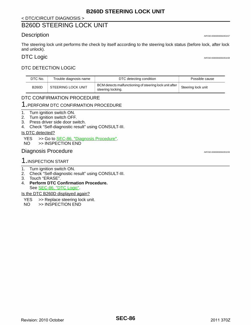
B260D STEERING LOCK UNIT
< DTC/CIRCUIT DIAGNOSIS >B260D STEERING LOCK UNIT
Description INFOID:0000000006353157
The steering lock unit performs the check by itself according to the steering lock status (before lock, after lockand unlock).
DTC Logic INFOID:0000000006353158
DTC DETECTION LOGIC
DTC CONFIRMATION PROCEDURE
1.PERFORM DTC CONFIRMATION PROCEDURE
1. Turn ignition switch ON.2. Turn ignition switch OFF.3. Press driver side door switch.4. Check “Self-diagnostic result” using CONSULT-III.Is DTC detected?YES >> Go to SEC-86, "Diagnosis Procedure".NO >> INSPECTION END
Diagnosis Procedure INFOID:0000000006353159
1.INSPECTION START
1. Turn ignition switch ON.2. Check “Self-diagnostic result” using CONSULT-III.3. Touch “ERASE”.4. Perform DTC Confirmation Procedure.
See SEC-86, "DTC Logic".Is the DTC B260D displayed again?YES >> Replace steering lock unit.NO >> INSPECTION END
DTC No. Trouble diagnosis name DTC detecting condition Possible cause
B260D STEERING LOCK UNITBCM detects malfunctioning of steering lock unit after steering locking.
Steering lock unit
SEC-86Revision: 2010 October 2011 370Z
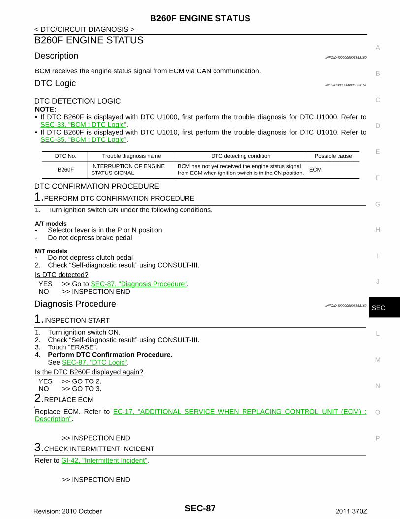
B260F ENGINE STATUS
C
D
E
F
G
H
I
J
L
M
A
B
EC
N
O
P
< DTC/CIRCUIT DIAGNOSIS >
S
B260F ENGINE STATUS
Description INFOID:0000000006353160
BCM receives the engine status signal from ECM via CAN communication.
DTC Logic INFOID:0000000006353161
DTC DETECTION LOGICNOTE:• If DTC B260F is displayed with DTC U1000, first perform the trouble diagnosis for DTC U1000. Refer to
SEC-33, "BCM : DTC Logic".• If DTC B260F is displayed with DTC U1010, first perform the trouble diagnosis for DTC U1010. Refer to
SEC-35, "BCM : DTC Logic".
DTC CONFIRMATION PROCEDURE
1.PERFORM DTC CONFIRMATION PROCEDURE
1. Turn ignition switch ON under the following conditions.
A/T models- Selector lever is in the P or N position- Do not depress brake pedal
M/T models- Do not depress clutch pedal2. Check “Self-diagnostic result” using CONSULT-III.Is DTC detected?YES >> Go to SEC-87, "Diagnosis Procedure".NO >> INSPECTION END
Diagnosis Procedure INFOID:0000000006353162
1.INSPECTION START
1. Turn ignition switch ON.2. Check “Self-diagnostic result” using CONSULT-III.3. Touch “ERASE”.4. Perform DTC Confirmation Procedure.
See SEC-87, "DTC Logic".Is the DTC B260F displayed again?YES >> GO TO 2.NO >> GO TO 3.
2.REPLACE ECM
Replace ECM. Refer to EC-17, "ADDITIONAL SERVICE WHEN REPLACING CONTROL UNIT (ECM) :Description".
>> INSPECTION END
3.CHECK INTERMITTENT INCIDENT
Refer to GI-42, "Intermittent Incident".
>> INSPECTION END
DTC No. Trouble diagnosis name DTC detecting condition Possible cause
B260FINTERRUPTION OF ENGINE STATUS SIGNAL
BCM has not yet received the engine status signal from ECM when ignition switch is in the ON position.
ECM
SEC-87Revision: 2010 October 2011 370Z
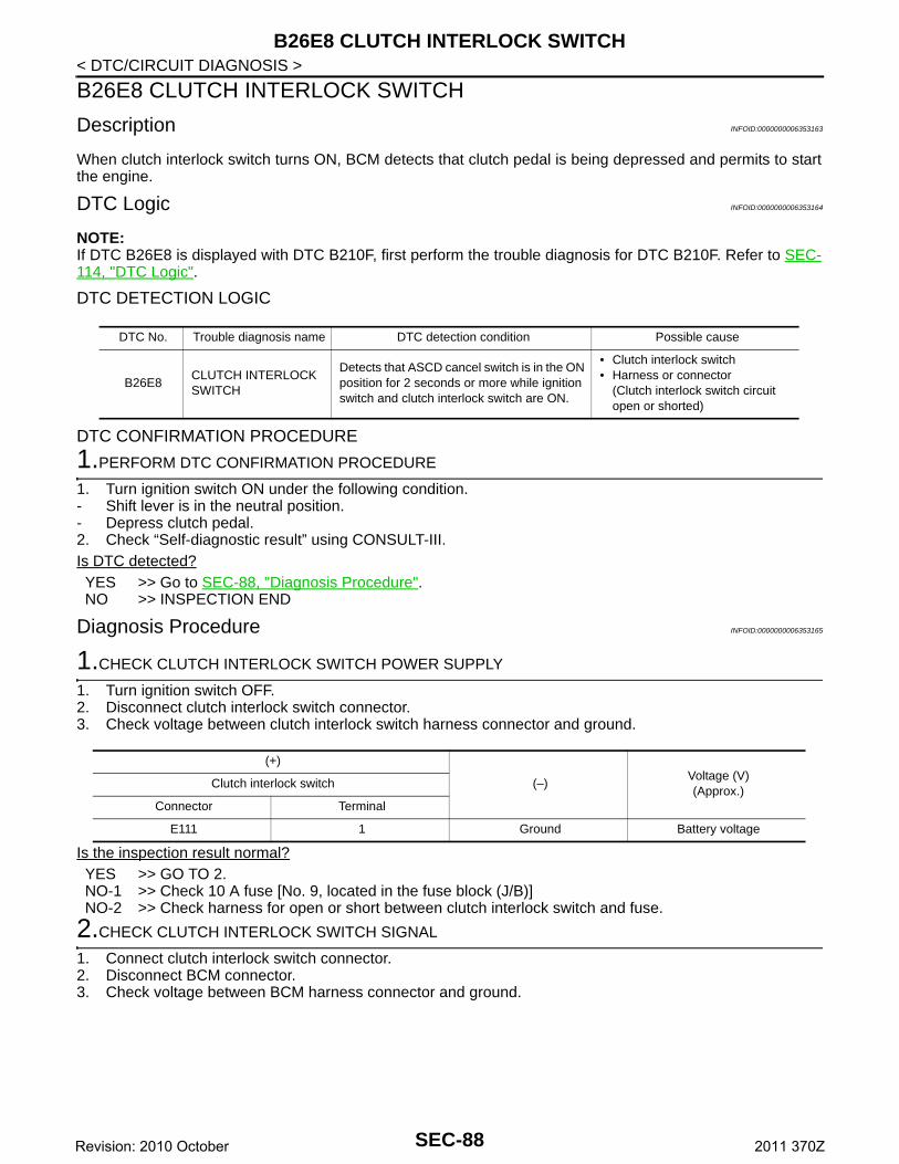
B26E8 CLUTCH INTERLOCK SWITCH
< DTC/CIRCUIT DIAGNOSIS >B26E8 CLUTCH INTERLOCK SWITCH
Description INFOID:0000000006353163
When clutch interlock switch turns ON, BCM detects that clutch pedal is being depressed and permits to startthe engine.
DTC Logic INFOID:0000000006353164
NOTE:If DTC B26E8 is displayed with DTC B210F, first perform the trouble diagnosis for DTC B210F. Refer to SEC-114, "DTC Logic".
DTC DETECTION LOGIC
DTC CONFIRMATION PROCEDURE
1.PERFORM DTC CONFIRMATION PROCEDURE
1. Turn ignition switch ON under the following condition.- Shift lever is in the neutral position.- Depress clutch pedal.2. Check “Self-diagnostic result” using CONSULT-III.Is DTC detected?YES >> Go to SEC-88, "Diagnosis Procedure".NO >> INSPECTION END
Diagnosis Procedure INFOID:0000000006353165
1.CHECK CLUTCH INTERLOCK SWITCH POWER SUPPLY
1. Turn ignition switch OFF.2. Disconnect clutch interlock switch connector.3. Check voltage between clutch interlock switch harness connector and ground.
Is the inspection result normal?YES >> GO TO 2.NO-1 >> Check 10 A fuse [No. 9, located in the fuse block (J/B)]NO-2 >> Check harness for open or short between clutch interlock switch and fuse.
2.CHECK CLUTCH INTERLOCK SWITCH SIGNAL
1. Connect clutch interlock switch connector.2. Disconnect BCM connector.3. Check voltage between BCM harness connector and ground.
DTC No. Trouble diagnosis name DTC detection condition Possible cause
B26E8CLUTCH INTERLOCK SWITCH
Detects that ASCD cancel switch is in the ON position for 2 seconds or more while ignition switch and clutch interlock switch are ON.
• Clutch interlock switch • Harness or connector
(Clutch interlock switch circuit open or shorted)
(+)
(–)Voltage (V)(Approx.)
Clutch interlock switch
Connector Terminal
E111 1 Ground Battery voltage
SEC-88Revision: 2010 October 2011 370Z
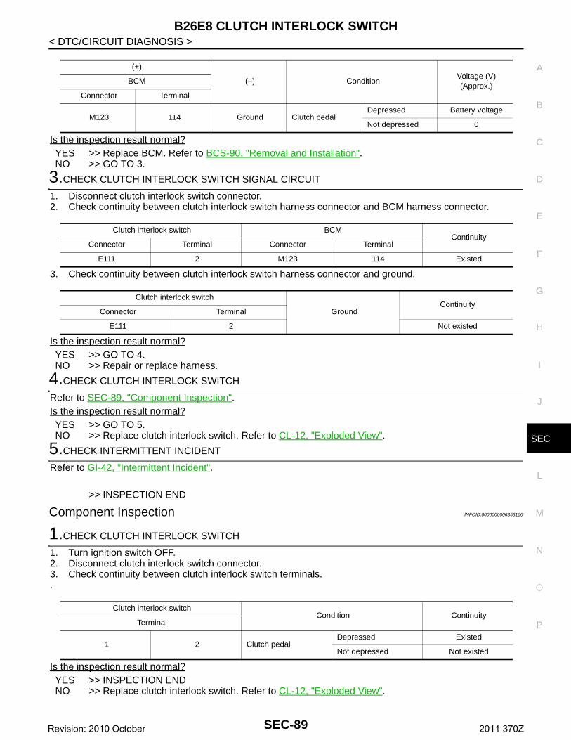
B26E8 CLUTCH INTERLOCK SWITCH
C
D
E
F
G
H
I
J
L
M
A
B
EC
N
O
P
< DTC/CIRCUIT DIAGNOSIS >
S
Is the inspection result normal?YES >> Replace BCM. Refer to BCS-90, "Removal and Installation".NO >> GO TO 3.
3.CHECK CLUTCH INTERLOCK SWITCH SIGNAL CIRCUIT
1. Disconnect clutch interlock switch connector.2. Check continuity between clutch interlock switch harness connector and BCM harness connector.
3. Check continuity between clutch interlock switch harness connector and ground.
Is the inspection result normal?YES >> GO TO 4.NO >> Repair or replace harness.
4.CHECK CLUTCH INTERLOCK SWITCH
Refer to SEC-89, "Component Inspection".Is the inspection result normal?YES >> GO TO 5.NO >> Replace clutch interlock switch. Refer to CL-12, "Exploded View".
5.CHECK INTERMITTENT INCIDENT
Refer to GI-42, "Intermittent Incident".
>> INSPECTION END
Component Inspection INFOID:0000000006353166
1.CHECK CLUTCH INTERLOCK SWITCH
1. Turn ignition switch OFF.2. Disconnect clutch interlock switch connector.3. Check continuity between clutch interlock switch terminals..
Is the inspection result normal?YES >> INSPECTION ENDNO >> Replace clutch interlock switch. Refer to CL-12, "Exploded View".
(+)
(–) ConditionVoltage (V)(Approx.)
BCM
Connector Terminal
M123 114 Ground Clutch pedalDepressed Battery voltage
Not depressed 0
Clutch interlock switch BCMContinuity
Connector Terminal Connector Terminal
E111 2 M123 114 Existed
Clutch interlock switch
GroundContinuity
Connector Terminal
E111 2 Not existed
Clutch interlock switchCondition Continuity
Terminal
1 2 Clutch pedalDepressed Existed
Not depressed Not existed
SEC-89Revision: 2010 October 2011 370Z
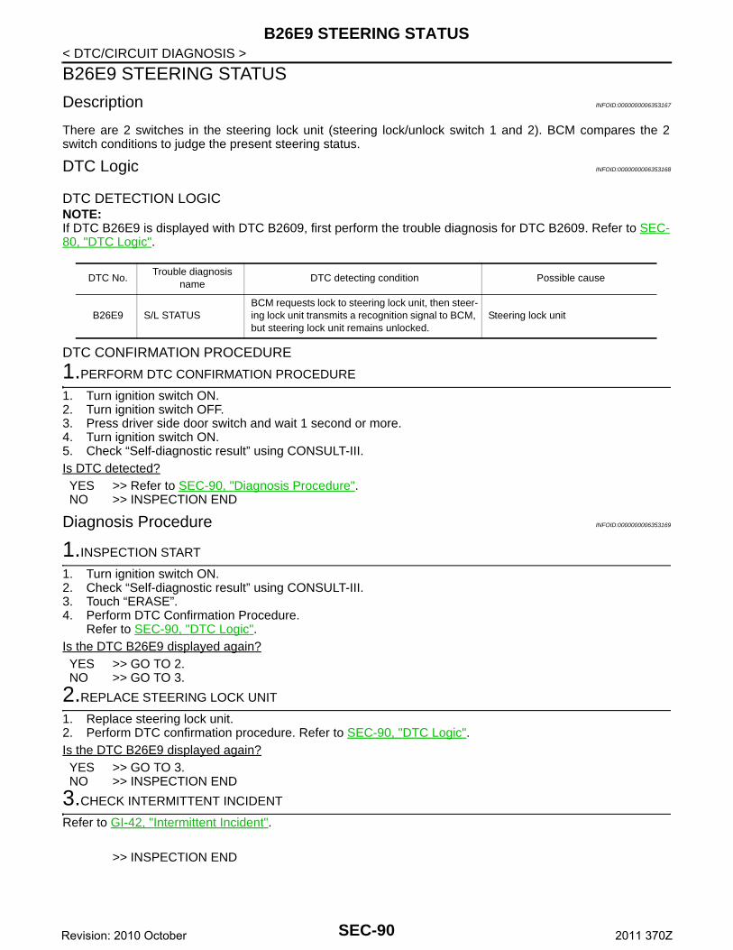
B26E9 STEERING STATUS
< DTC/CIRCUIT DIAGNOSIS >B26E9 STEERING STATUS
Description INFOID:0000000006353167
There are 2 switches in the steering lock unit (steering lock/unlock switch 1 and 2). BCM compares the 2switch conditions to judge the present steering status.
DTC Logic INFOID:0000000006353168
DTC DETECTION LOGICNOTE:If DTC B26E9 is displayed with DTC B2609, first perform the trouble diagnosis for DTC B2609. Refer to SEC-80, "DTC Logic".
DTC CONFIRMATION PROCEDURE
1.PERFORM DTC CONFIRMATION PROCEDURE
1. Turn ignition switch ON.2. Turn ignition switch OFF.3. Press driver side door switch and wait 1 second or more.4. Turn ignition switch ON.5. Check “Self-diagnostic result” using CONSULT-III.Is DTC detected?YES >> Refer to SEC-90, "Diagnosis Procedure".NO >> INSPECTION END
Diagnosis Procedure INFOID:0000000006353169
1.INSPECTION START
1. Turn ignition switch ON.2. Check “Self-diagnostic result” using CONSULT-III.3. Touch “ERASE”.4. Perform DTC Confirmation Procedure.
Refer to SEC-90, "DTC Logic".Is the DTC B26E9 displayed again?YES >> GO TO 2.NO >> GO TO 3.
2.REPLACE STEERING LOCK UNIT
1. Replace steering lock unit.2. Perform DTC confirmation procedure. Refer to SEC-90, "DTC Logic".Is the DTC B26E9 displayed again?YES >> GO TO 3.NO >> INSPECTION END
3.CHECK INTERMITTENT INCIDENT
Refer to GI-42, "Intermittent Incident".
>> INSPECTION END
DTC No.Trouble diagnosis
nameDTC detecting condition Possible cause
B26E9 S/L STATUSBCM requests lock to steering lock unit, then steer-ing lock unit transmits a recognition signal to BCM, but steering lock unit remains unlocked.
Steering lock unit
SEC-90Revision: 2010 October 2011 370Z
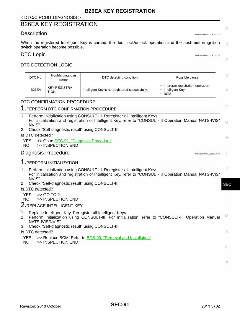
B26EA KEY REGISTRATION
C
D
E
F
G
H
I
J
L
M
A
B
EC
N
O
P
< DTC/CIRCUIT DIAGNOSIS >
S
B26EA KEY REGISTRATION
Description INFOID:0000000006353170
When the registered Intelligent Key is carried, the door lock/unlock operation and the push-button ignitionswitch operation become possible.
DTC Logic INFOID:0000000006353171
DTC DETECTION LOGIC
DTC CONFIRMATION PROCEDURE
1.PERFORM DTC CONFIRMATION PROCEDURE
1. Perform initialization using CONSULT-III. Reregister all Intelligent Keys.For initialization and registration of Intelligent Key, refer to “CONSULT-III Operation Manual NATS-IVIS/NVIS”.
2. Check “Self-diagnostic result” using CONSULT-III.Is DTC detected?YES >> Go to SEC-91, "Diagnosis Procedure"NO >> INSPECTION END
Diagnosis Procedure INFOID:0000000006353172
1.PERFORM INITIALIZATION
1. Perform initialization using CONSULT-III. Reregister all Intelligent Keys.For initialization and registration of Intelligent Key, refer to “CONSULT-III Operation Manual NATS-IVIS/NVIS”.
2. Check “Self-diagnostic result” using CONSULT-III.Is DTC detected?YES >> GO TO 2.NO >> INSPECTION END
2.REPLACE INTELLIGENT KEY
1. Replace Intelligent Key. Reregister all Intelligent Keys2. Perform initialization using CONSULT-III. For initialization, refer to “CONSULT-III Operation Manual
NATS-IVIS/NVIS”.3. Check “Self-diagnostic result” using CONSULT-III.Is DTC detected?YES >> Replace BCM. Refer to BCS-90, "Removal and Installation".NO >> INSPECTION END
DTC No.Trouble diagnosis
nameDTC detecting condition Possible cause
B26EAKEY REGISTRA-TION
Intelligent Key is not registered successfully.• Improper registration operation• Intelligent Key• BCM
SEC-91Revision: 2010 October 2011 370Z
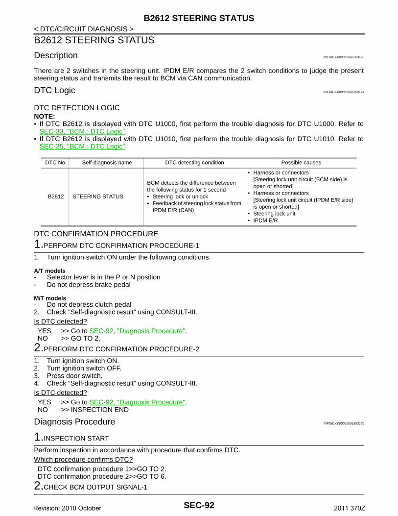
B2612 STEERING STATUS
< DTC/CIRCUIT DIAGNOSIS >B2612 STEERING STATUS
Description INFOID:0000000006353173
There are 2 switches in the steering unit. IPDM E/R compares the 2 switch conditions to judge the presentsteering status and transmits the result to BCM via CAN communication.
DTC Logic INFOID:0000000006353174
DTC DETECTION LOGICNOTE:• If DTC B2612 is displayed with DTC U1000, first perform the trouble diagnosis for DTC U1000. Refer to
SEC-33, "BCM : DTC Logic".• If DTC B2612 is displayed with DTC U1010, first perform the trouble diagnosis for DTC U1010. Refer to
SEC-35, "BCM : DTC Logic".
DTC CONFIRMATION PROCEDURE
1.PERFORM DTC CONFIRMATION PROCEDURE-1
1. Turn ignition switch ON under the following conditions.
A/T models- Selector lever is in the P or N position- Do not depress brake pedal
M/T models- Do not depress clutch pedal2. Check “Self-diagnostic result” using CONSULT-III.Is DTC detected?YES >> Go to SEC-92, "Diagnosis Procedure".NO >> GO TO 2.
2.PERFORM DTC CONFIRMATION PROCEDURE-2
1. Turn ignition switch ON.2. Turn ignition switch OFF.3. Press door switch.4. Check “Self-diagnostic result” using CONSULT-III.Is DTC detected?YES >> Go to SEC-92, "Diagnosis Procedure".NO >> INSPECTION END
Diagnosis Procedure INFOID:0000000006353175
1.INSPECTION START
Perform inspection in accordance with procedure that confirms DTC.Which procedure confirms DTC?DTC confirmation procedure 1>>GO TO 2.DTC confirmation procedure 2>>GO TO 6.
2.CHECK BCM OUTPUT SIGNAL-1
DTC No. Self-diagnosis name DTC detecting condition Possible causes
B2612 STEERING STATUS
BCM detects the difference between the following status for 1 second• Steering lock or unlock• Feedback of steering lock status from
IPDM E/R (CAN)
• Harness or connectors[Steering lock unit circuit (BCM side) is open or shorted]
• Harness or connectors[Steering lock unit circuit (IPDM E/R side) is open or shorted]
• Steering lock unit • IPDM E/R
SEC-92Revision: 2010 October 2011 370Z
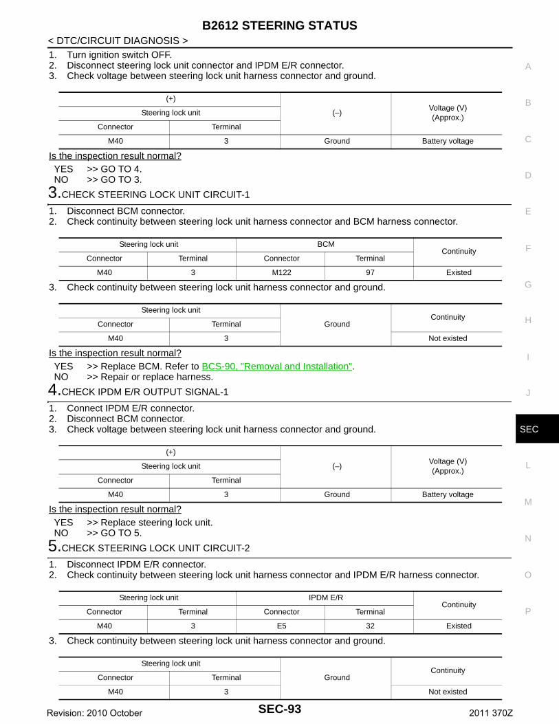
B2612 STEERING STATUS
C
D
E
F
G
H
I
J
L
M
A
B
EC
N
O
P
< DTC/CIRCUIT DIAGNOSIS >
S
1. Turn ignition switch OFF.2. Disconnect steering lock unit connector and IPDM E/R connector.3. Check voltage between steering lock unit harness connector and ground.
Is the inspection result normal?YES >> GO TO 4.NO >> GO TO 3.
3.CHECK STEERING LOCK UNIT CIRCUIT-1
1. Disconnect BCM connector.2. Check continuity between steering lock unit harness connector and BCM harness connector.
3. Check continuity between steering lock unit harness connector and ground.
Is the inspection result normal?YES >> Replace BCM. Refer to BCS-90, "Removal and Installation".NO >> Repair or replace harness.
4.CHECK IPDM E/R OUTPUT SIGNAL-1
1. Connect IPDM E/R connector.2. Disconnect BCM connector.3. Check voltage between steering lock unit harness connector and ground.
Is the inspection result normal?YES >> Replace steering lock unit.NO >> GO TO 5.
5.CHECK STEERING LOCK UNIT CIRCUIT-2
1. Disconnect IPDM E/R connector.2. Check continuity between steering lock unit harness connector and IPDM E/R harness connector.
3. Check continuity between steering lock unit harness connector and ground.
(+)
(–)Voltage (V)(Approx.)
Steering lock unit
Connector Terminal
M40 3 Ground Battery voltage
Steering lock unit BCMContinuity
Connector Terminal Connector Terminal
M40 3 M122 97 Existed
Steering lock unit
GroundContinuity
Connector Terminal
M40 3 Not existed
(+)
(–)Voltage (V)(Approx.)
Steering lock unit
Connector Terminal
M40 3 Ground Battery voltage
Steering lock unit IPDM E/RContinuity
Connector Terminal Connector Terminal
M40 3 E5 32 Existed
Steering lock unit
GroundContinuity
Connector Terminal
M40 3 Not existed
SEC-93Revision: 2010 October 2011 370Z
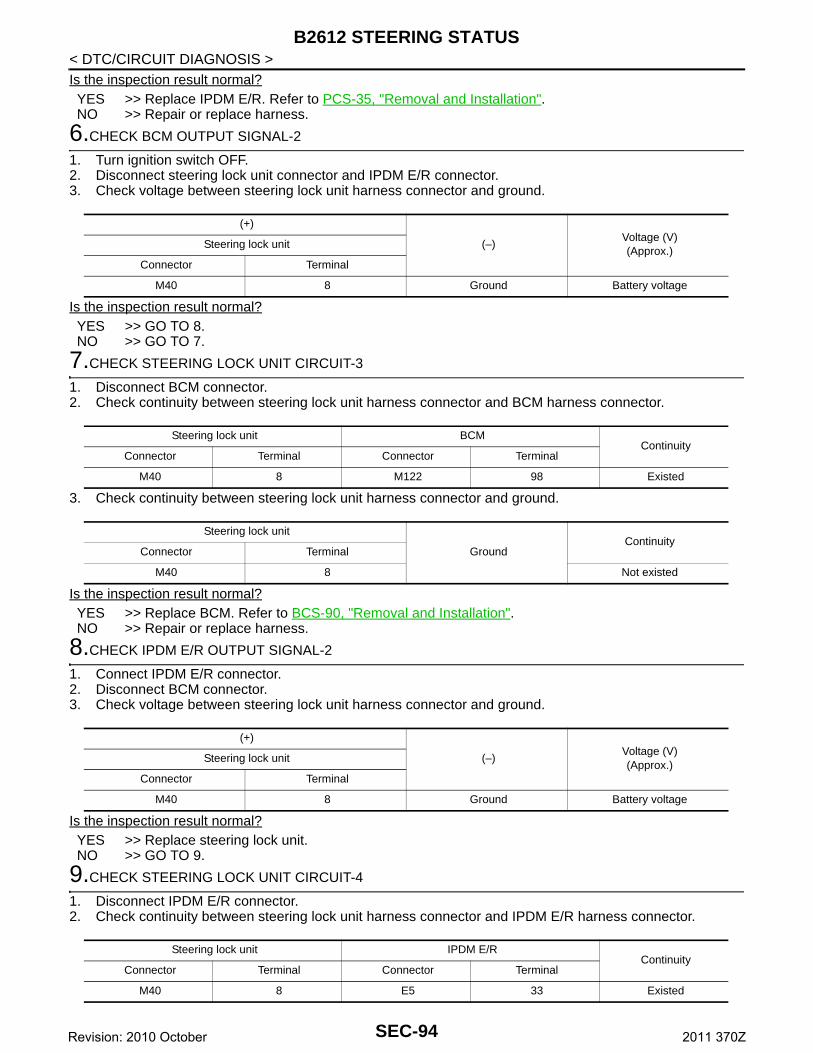
B2612 STEERING STATUS
< DTC/CIRCUIT DIAGNOSIS >Is the inspection result normal?YES >> Replace IPDM E/R. Refer to PCS-35, "Removal and Installation".NO >> Repair or replace harness.6.CHECK BCM OUTPUT SIGNAL-2
1. Turn ignition switch OFF.2. Disconnect steering lock unit connector and IPDM E/R connector.3. Check voltage between steering lock unit harness connector and ground.
Is the inspection result normal?YES >> GO TO 8.NO >> GO TO 7.
7.CHECK STEERING LOCK UNIT CIRCUIT-3
1. Disconnect BCM connector.2. Check continuity between steering lock unit harness connector and BCM harness connector.
3. Check continuity between steering lock unit harness connector and ground.
Is the inspection result normal?YES >> Replace BCM. Refer to BCS-90, "Removal and Installation".NO >> Repair or replace harness.
8.CHECK IPDM E/R OUTPUT SIGNAL-2
1. Connect IPDM E/R connector.2. Disconnect BCM connector.3. Check voltage between steering lock unit harness connector and ground.
Is the inspection result normal?YES >> Replace steering lock unit.NO >> GO TO 9.
9.CHECK STEERING LOCK UNIT CIRCUIT-4
1. Disconnect IPDM E/R connector.2. Check continuity between steering lock unit harness connector and IPDM E/R harness connector.
(+)
(–)Voltage (V)(Approx.)
Steering lock unit
Connector Terminal
M40 8 Ground Battery voltage
Steering lock unit BCMContinuity
Connector Terminal Connector Terminal
M40 8 M122 98 Existed
Steering lock unit
GroundContinuity
Connector Terminal
M40 8 Not existed
(+)
(–)Voltage (V)(Approx.)
Steering lock unit
Connector Terminal
M40 8 Ground Battery voltage
Steering lock unit IPDM E/RContinuity
Connector Terminal Connector Terminal
M40 8 E5 33 Existed
SEC-94Revision: 2010 October 2011 370Z
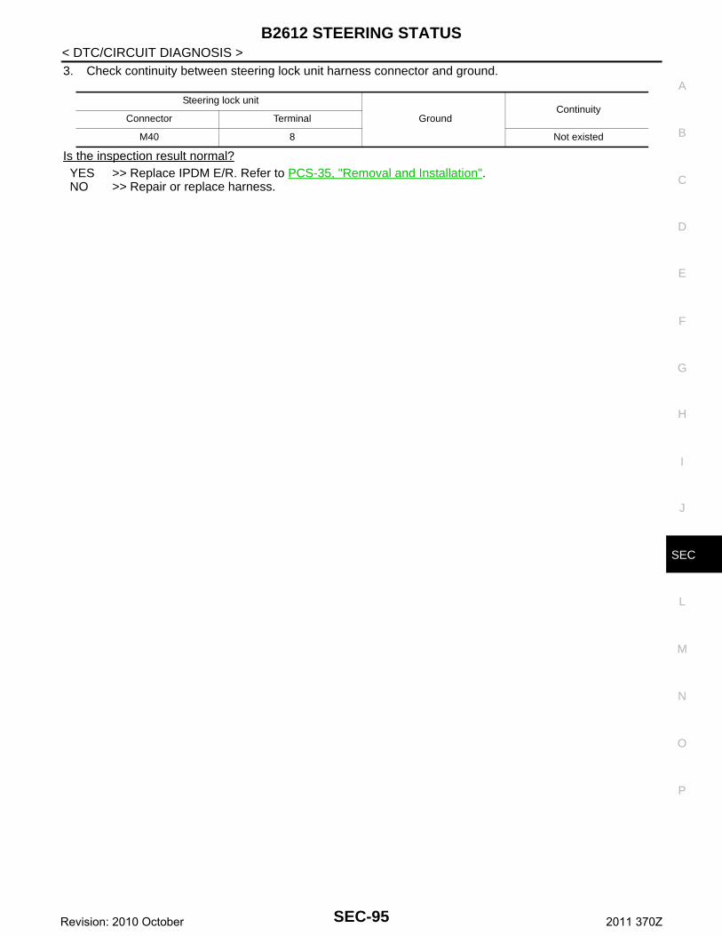
B2612 STEERING STATUS
C
D
E
F
G
H
I
J
L
M
A
B
EC
N
O
P
< DTC/CIRCUIT DIAGNOSIS >
S
3. Check continuity between steering lock unit harness connector and ground.
Is the inspection result normal?YES >> Replace IPDM E/R. Refer to PCS-35, "Removal and Installation".NO >> Repair or replace harness.
Steering lock unit
GroundContinuity
Connector Terminal
M40 8 Not existed
SEC-95Revision: 2010 October 2011 370Z
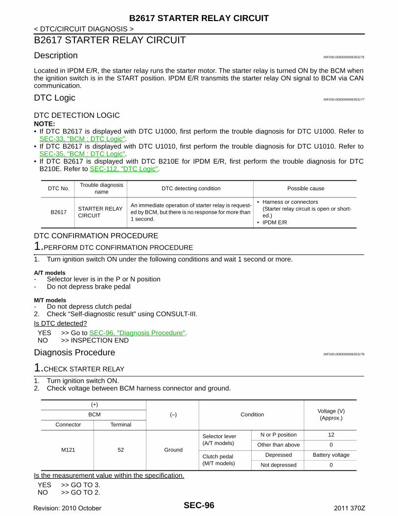
B2617 STARTER RELAY CIRCUIT
< DTC/CIRCUIT DIAGNOSIS >B2617 STARTER RELAY CIRCUIT
Description INFOID:0000000006353176
Located in IPDM E/R, the starter relay runs the starter motor. The starter relay is turned ON by the BCM whenthe ignition switch is in the START position. IPDM E/R transmits the starter relay ON signal to BCM via CANcommunication.
DTC Logic INFOID:0000000006353177
DTC DETECTION LOGICNOTE:• If DTC B2617 is displayed with DTC U1000, first perform the trouble diagnosis for DTC U1000. Refer to
SEC-33, "BCM : DTC Logic".• If DTC B2617 is displayed with DTC U1010, first perform the trouble diagnosis for DTC U1010. Refer to
SEC-35, "BCM : DTC Logic".• If DTC B2617 is displayed with DTC B210E for IPDM E/R, first perform the trouble diagnosis for DTC
B210E. Refer to SEC-112, "DTC Logic".
DTC CONFIRMATION PROCEDURE
1.PERFORM DTC CONFIRMATION PROCEDURE
1. Turn ignition switch ON under the following conditions and wait 1 second or more.
A/T models- Selector lever is in the P or N position- Do not depress brake pedal
M/T models- Do not depress clutch pedal2. Check “Self-diagnostic result” using CONSULT-III.Is DTC detected?YES >> Go to SEC-96, "Diagnosis Procedure".NO >> INSPECTION END
Diagnosis Procedure INFOID:0000000006353178
1.CHECK STARTER RELAY
1. Turn ignition switch ON.2. Check voltage between BCM harness connector and ground.
Is the measurement value within the specification.YES >> GO TO 3.NO >> GO TO 2.
DTC No.Trouble diagnosis
nameDTC detecting condition Possible cause
B2617STARTER RELAY CIRCUIT
An immediate operation of starter relay is request-ed by BCM, but there is no response for more than 1 second.
• Harness or connectors(Starter relay circuit is open or short-ed.)
• IPDM E/R
(+)
(–) ConditionVoltage (V)(Approx.)
BCM
Connector Terminal
M121 52 Ground
Selector lever(A/T models)
N or P position 12
Other than above 0
Clutch pedal(M/T models)
Depressed Battery voltage
Not depressed 0
SEC-96Revision: 2010 October 2011 370Z
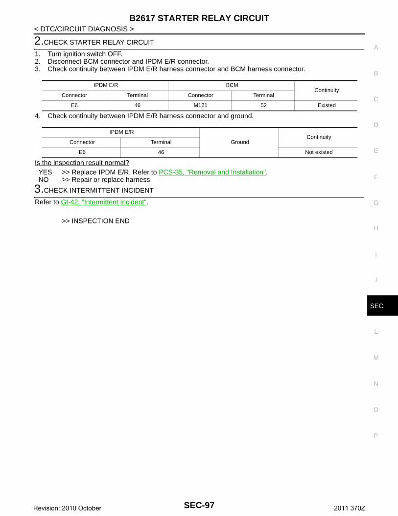
B2617 STARTER RELAY CIRCUIT
C
D
E
F
G
H
I
J
L
M
A
B
EC
N
O
P
< DTC/CIRCUIT DIAGNOSIS >
S
2.CHECK STARTER RELAY CIRCUIT
1. Turn ignition switch OFF.2. Disconnect BCM connector and IPDM E/R connector.3. Check continuity between IPDM E/R harness connector and BCM harness connector.
4. Check continuity between IPDM E/R harness connector and ground.
Is the inspection result normal?YES >> Replace IPDM E/R. Refer to PCS-35, "Removal and Installation".NO >> Repair or replace harness.
3.CHECK INTERMITTENT INCIDENT
Refer to GI-42, "Intermittent Incident".
>> INSPECTION END
IPDM E/R BCMContinuity
Connector Terminal Connector Terminal
E6 46 M121 52 Existed
IPDM E/R
GroundContinuity
Connector Terminal
E6 46 Not existed
SEC-97Revision: 2010 October 2011 370Z
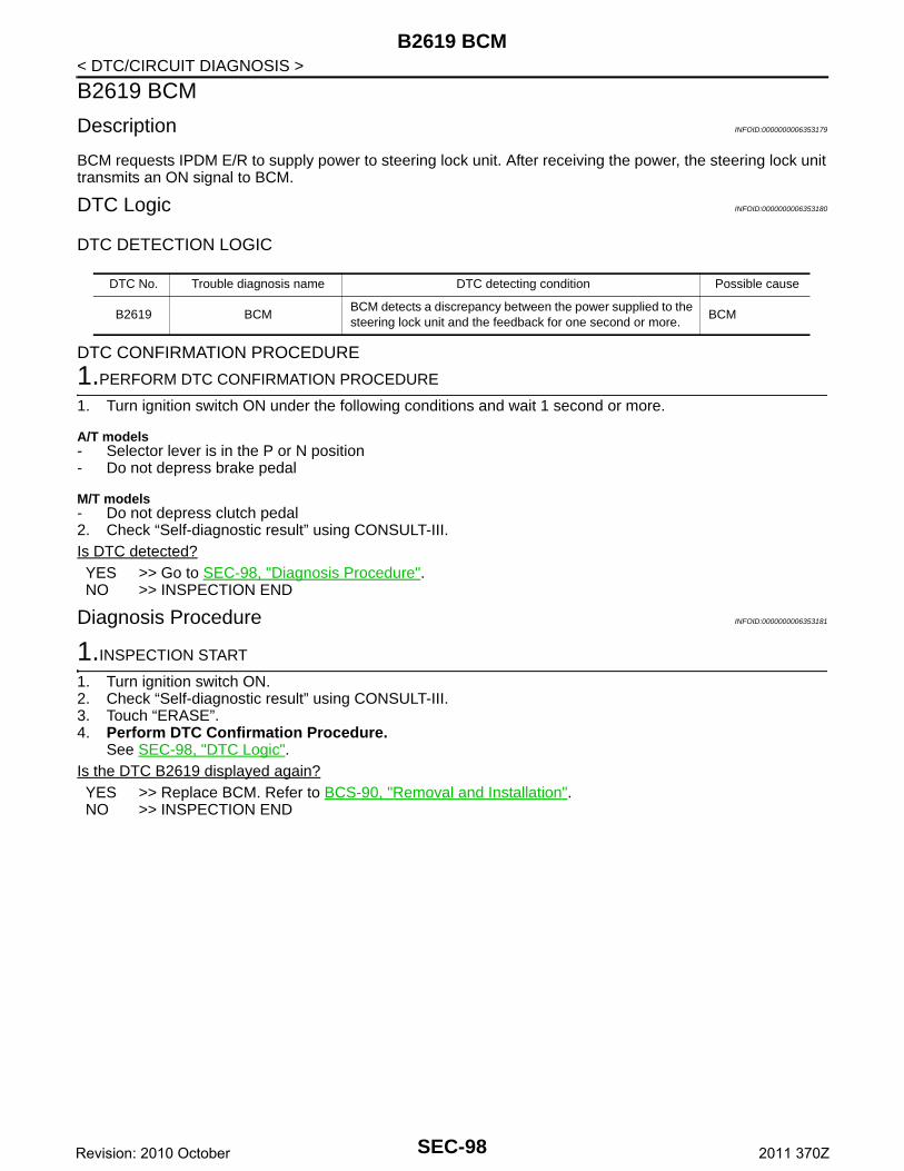
B2619 BCM
< DTC/CIRCUIT DIAGNOSIS >B2619 BCM
Description INFOID:0000000006353179
BCM requests IPDM E/R to supply power to steering lock unit. After receiving the power, the steering lock unittransmits an ON signal to BCM.
DTC Logic INFOID:0000000006353180
DTC DETECTION LOGIC
DTC CONFIRMATION PROCEDURE
1.PERFORM DTC CONFIRMATION PROCEDURE
1. Turn ignition switch ON under the following conditions and wait 1 second or more.
A/T models- Selector lever is in the P or N position- Do not depress brake pedal
M/T models- Do not depress clutch pedal2. Check “Self-diagnostic result” using CONSULT-III.Is DTC detected?YES >> Go to SEC-98, "Diagnosis Procedure".NO >> INSPECTION END
Diagnosis Procedure INFOID:0000000006353181
1.INSPECTION START
1. Turn ignition switch ON.2. Check “Self-diagnostic result” using CONSULT-III.3. Touch “ERASE”.4. Perform DTC Confirmation Procedure.
See SEC-98, "DTC Logic".Is the DTC B2619 displayed again?YES >> Replace BCM. Refer to BCS-90, "Removal and Installation".NO >> INSPECTION END
DTC No. Trouble diagnosis name DTC detecting condition Possible cause
B2619 BCMBCM detects a discrepancy between the power supplied to the steering lock unit and the feedback for one second or more.
BCM
SEC-98Revision: 2010 October 2011 370Z
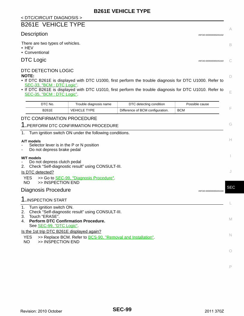
B261E VEHICLE TYPE
C
D
E
F
G
H
I
J
L
M
A
B
EC
N
O
P
< DTC/CIRCUIT DIAGNOSIS >
S
B261E VEHICLE TYPE
Description INFOID:0000000006353182
There are two types of vehicles.• HEV• Conventional
DTC Logic INFOID:0000000006353183
DTC DETECTION LOGICNOTE:• If DTC B261E is displayed with DTC U1000, first perform the trouble diagnosis for DTC U1000. Refer to
SEC-33, "BCM : DTC Logic".• If DTC B261E is displayed with DTC U1010, first perform the trouble diagnosis for DTC U1010. Refer to
SEC-35, "BCM : DTC Logic".
DTC CONFIRMATION PROCEDURE
1.PERFORM DTC CONFIRMATION PROCEDURE
1. Turn ignition switch ON under the following conditions.
A/T models- Selector lever is in the P or N position- Do not depress brake pedal
M/T models- Do not depress clutch pedal2. Check “Self-diagnostic result” using CONSULT-III.Is DTC detected?YES >> Go to SEC-99, "Diagnosis Procedure".NO >> INSPECTION END
Diagnosis Procedure INFOID:0000000006353184
1.INSPECTION START
1. Turn ignition switch ON.2. Check “Self-diagnostic result” using CONSULT-III.3. Touch “ERASE”.4. Perform DTC Confirmation Procedure.
See SEC-99, "DTC Logic".Is the 1st trip DTC B261E displayed again?YES >> Replace BCM. Refer to BCS-90, "Removal and Installation".NO >> INSPECTION END
DTC No. Trouble diagnosis name DTC detecting condition Possible cause
B261E VEHICLE TYPE Difference of BCM configuration. BCM
SEC-99Revision: 2010 October 2011 370Z
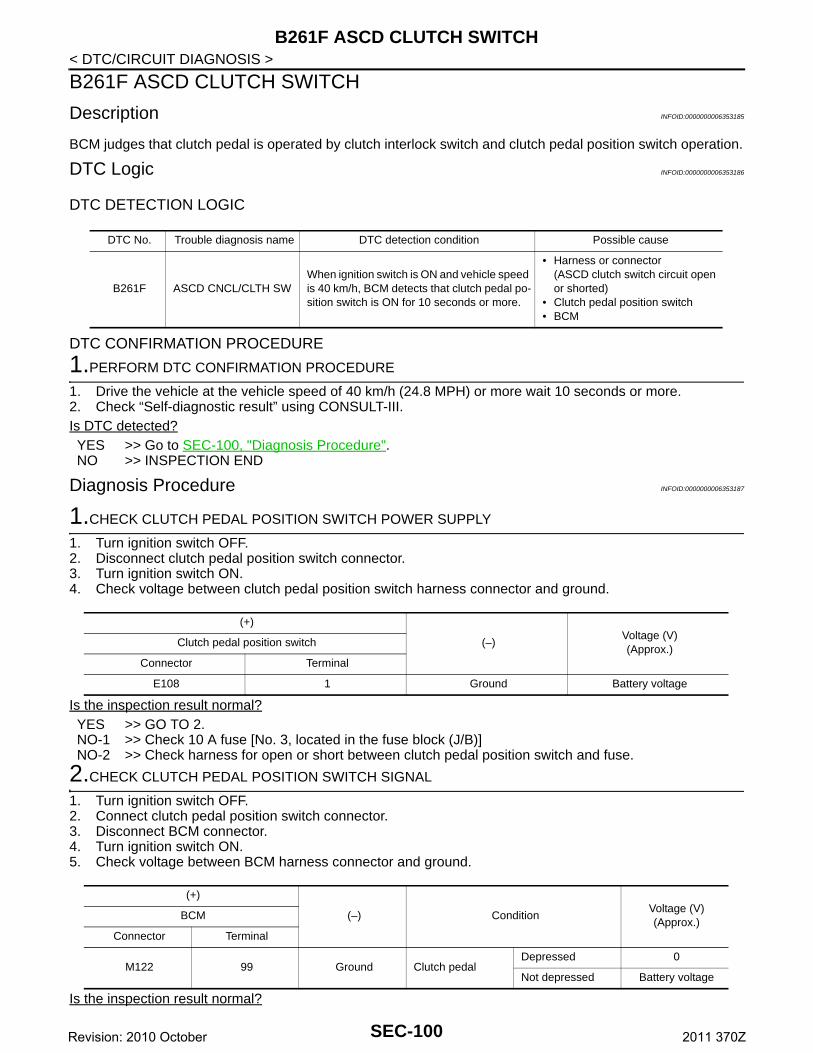
B261F ASCD CLUTCH SWITCH
< DTC/CIRCUIT DIAGNOSIS >B261F ASCD CLUTCH SWITCH
Description INFOID:0000000006353185
BCM judges that clutch pedal is operated by clutch interlock switch and clutch pedal position switch operation.
DTC Logic INFOID:0000000006353186
DTC DETECTION LOGIC
DTC CONFIRMATION PROCEDURE
1.PERFORM DTC CONFIRMATION PROCEDURE
1. Drive the vehicle at the vehicle speed of 40 km/h (24.8 MPH) or more wait 10 seconds or more.2. Check “Self-diagnostic result” using CONSULT-III.Is DTC detected?YES >> Go to SEC-100, "Diagnosis Procedure".NO >> INSPECTION END
Diagnosis Procedure INFOID:0000000006353187
1.CHECK CLUTCH PEDAL POSITION SWITCH POWER SUPPLY
1. Turn ignition switch OFF.2. Disconnect clutch pedal position switch connector.3. Turn ignition switch ON.4. Check voltage between clutch pedal position switch harness connector and ground.
Is the inspection result normal?YES >> GO TO 2.NO-1 >> Check 10 A fuse [No. 3, located in the fuse block (J/B)]NO-2 >> Check harness for open or short between clutch pedal position switch and fuse.
2.CHECK CLUTCH PEDAL POSITION SWITCH SIGNAL
1. Turn ignition switch OFF.2. Connect clutch pedal position switch connector.3. Disconnect BCM connector.4. Turn ignition switch ON.5. Check voltage between BCM harness connector and ground.
Is the inspection result normal?
DTC No. Trouble diagnosis name DTC detection condition Possible cause
B261F ASCD CNCL/CLTH SWWhen ignition switch is ON and vehicle speed is 40 km/h, BCM detects that clutch pedal po-sition switch is ON for 10 seconds or more.
• Harness or connector(ASCD clutch switch circuit open or shorted)
• Clutch pedal position switch • BCM
(+)
(–)Voltage (V)(Approx.)
Clutch pedal position switch
Connector Terminal
E108 1 Ground Battery voltage
(+)
(–) ConditionVoltage (V)(Approx.)
BCM
Connector Terminal
M122 99 Ground Clutch pedalDepressed 0
Not depressed Battery voltage
SEC-100Revision: 2010 October 2011 370Z
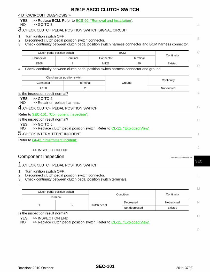
B261F ASCD CLUTCH SWITCH
C
D
E
F
G
H
I
J
L
M
A
B
EC
N
O
P
< DTC/CIRCUIT DIAGNOSIS >
S
YES >> Replace BCM. Refer to BCS-90, "Removal and Installation".NO >> GO TO 3.
3.CHECK CLUTCH PEDAL POSITION SWITCH SIGNAL CIRCUIT
1. Turn ignition switch OFF.2. Disconnect clutch pedal position switch connector.3. Check continuity between clutch pedal position switch harness connector and BCM harness connector.
4. Check continuity between clutch pedal position switch harness connector and ground.
Is the inspection result normal?YES >> GO TO 4.NO >> Repair or replace harness.
4.CHECK CLUTCH PEDAL POSITION SWITCH
Refer to SEC-101, "Component Inspection".Is the inspection result normal?YES >> GO TO 5.NO >> Replace clutch pedal position switch. Refer to CL-12, "Exploded View".
5.CHECK INTERMITTENT INCIDENT
Refer to GI-42, "Intermittent Incident".
>> INSPECTION END
Component Inspection INFOID:0000000006353188
1.CHECK CLUTCH PEDAL POSITION SWITCH
1. Turn ignition switch OFF.2. Disconnect clutch pedal position switch connector.3. Check continuity between clutch pedal position switch terminals..
Is the inspection result normal?YES >> INSPECTION ENDNO >> Replace clutch pedal position switch. Refer to CL-12, "Exploded View".
Clutch pedal position switch BCMContinuity
Connector Terminal Connector Terminal
E108 2 M122 99 Existed
Clutch pedal position switch
GroundContinuity
Connector Terminal
E108 2 Not existed
Clutch pedal position switchCondition Continuity
Terminal
1 2 Clutch pedalDepressed Not existed
Not depressed Existed
SEC-101Revision: 2010 October 2011 370Z
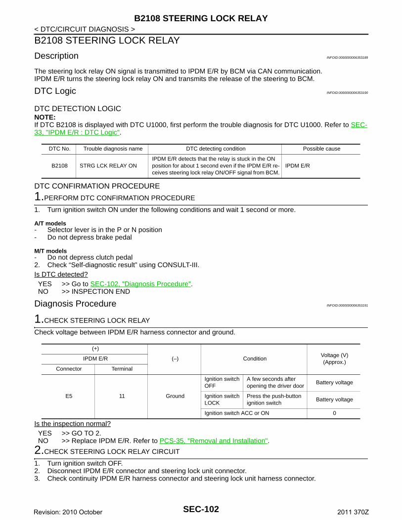
B2108 STEERING LOCK RELAY
< DTC/CIRCUIT DIAGNOSIS >B2108 STEERING LOCK RELAY
Description INFOID:0000000006353189
The steering lock relay ON signal is transmitted to IPDM E/R by BCM via CAN communication.IPDM E/R turns the steering lock relay ON and transmits the release of the steering to BCM.
DTC Logic INFOID:0000000006353190
DTC DETECTION LOGICNOTE:If DTC B2108 is displayed with DTC U1000, first perform the trouble diagnosis for DTC U1000. Refer to SEC-33, "IPDM E/R : DTC Logic".
DTC CONFIRMATION PROCEDURE
1.PERFORM DTC CONFIRMATION PROCEDURE
1. Turn ignition switch ON under the following conditions and wait 1 second or more.
A/T models- Selector lever is in the P or N position- Do not depress brake pedal
M/T models- Do not depress clutch pedal2. Check “Self-diagnostic result” using CONSULT-III.Is DTC detected?YES >> Go to SEC-102, "Diagnosis Procedure".NO >> INSPECTION END
Diagnosis Procedure INFOID:0000000006353191
1.CHECK STEERING LOCK RELAY
Check voltage between IPDM E/R harness connector and ground.
Is the inspection normal?YES >> GO TO 2.NO >> Replace IPDM E/R. Refer to PCS-35, "Removal and Installation".
2.CHECK STEERING LOCK RELAY CIRCUIT
1. Turn ignition switch OFF.2. Disconnect IPDM E/R connector and steering lock unit connector.3. Check continuity IPDM E/R harness connector and steering lock unit harness connector.
DTC No. Trouble diagnosis name DTC detecting condition Possible cause
B2108 STRG LCK RELAY ONIPDM E/R detects that the relay is stuck in the ON position for about 1 second even if the IPDM E/R re-ceives steering lock relay ON/OFF signal from BCM.
IPDM E/R
(+)
(–) ConditionVoltage (V)(Approx.)
IPDM E/R
Connector Terminal
E5 11 Ground
Ignition switch OFF
A few seconds after opening the driver door
Battery voltage
Ignition switch LOCK
Press the push-button ignition switch
Battery voltage
Ignition switch ACC or ON 0
SEC-102Revision: 2010 October 2011 370Z
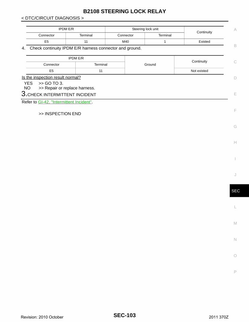
B2108 STEERING LOCK RELAY
C
D
E
F
G
H
I
J
L
M
A
B
EC
N
O
P
< DTC/CIRCUIT DIAGNOSIS >
S
4. Check continuity IPDM E/R harness connector and ground.
Is the inspection result normal?YES >> GO TO 3.NO >> Repair or replace harness.
3.CHECK INTERMITTENT INCIDENT
Refer to GI-42, "Intermittent Incident".
>> INSPECTION END
IPDM E/R Steering lock unitContinuity
Connector Terminal Connector Terminal
E5 11 M40 1 Existed
IPDM E/R
GroundContinuity
Connector Terminal
E5 11 Not existed
SEC-103Revision: 2010 October 2011 370Z
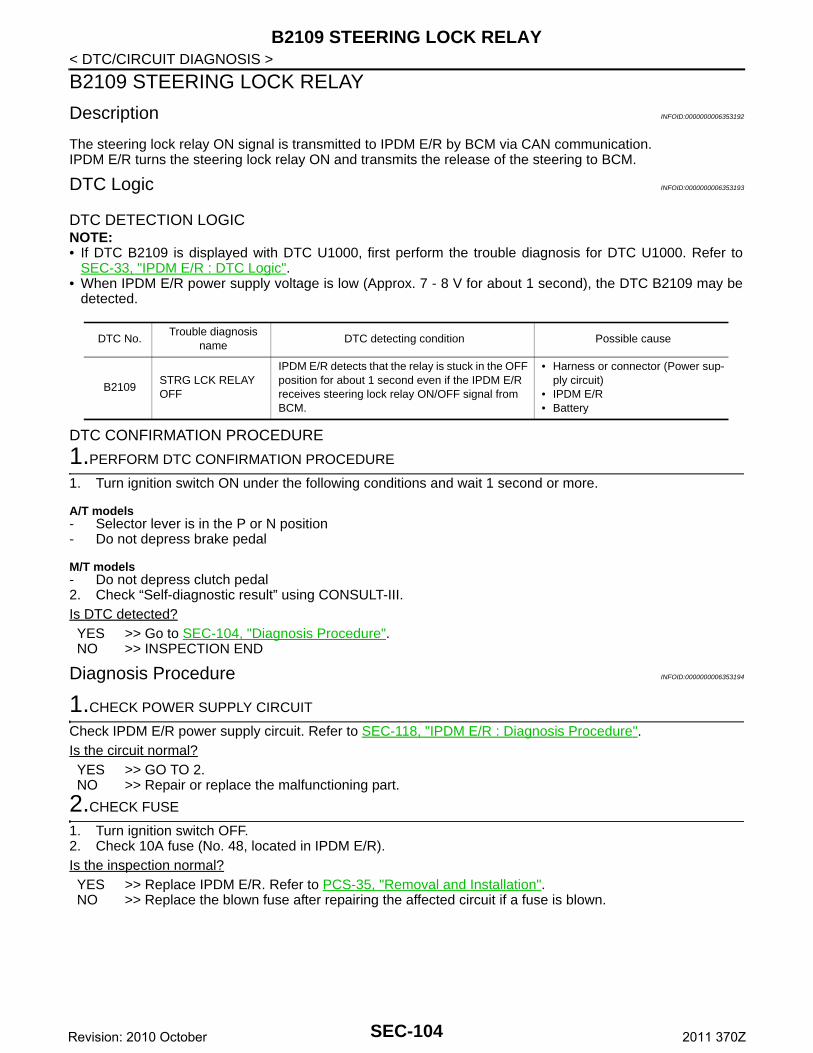
B2109 STEERING LOCK RELAY
< DTC/CIRCUIT DIAGNOSIS >B2109 STEERING LOCK RELAY
Description INFOID:0000000006353192
The steering lock relay ON signal is transmitted to IPDM E/R by BCM via CAN communication.IPDM E/R turns the steering lock relay ON and transmits the release of the steering to BCM.
DTC Logic INFOID:0000000006353193
DTC DETECTION LOGICNOTE:• If DTC B2109 is displayed with DTC U1000, first perform the trouble diagnosis for DTC U1000. Refer to
SEC-33, "IPDM E/R : DTC Logic".• When IPDM E/R power supply voltage is low (Approx. 7 - 8 V for about 1 second), the DTC B2109 may be
detected.
DTC CONFIRMATION PROCEDURE
1.PERFORM DTC CONFIRMATION PROCEDURE
1. Turn ignition switch ON under the following conditions and wait 1 second or more.
A/T models- Selector lever is in the P or N position- Do not depress brake pedal
M/T models- Do not depress clutch pedal2. Check “Self-diagnostic result” using CONSULT-III.Is DTC detected?YES >> Go to SEC-104, "Diagnosis Procedure".NO >> INSPECTION END
Diagnosis Procedure INFOID:0000000006353194
1.CHECK POWER SUPPLY CIRCUIT
Check IPDM E/R power supply circuit. Refer to SEC-118, "IPDM E/R : Diagnosis Procedure".Is the circuit normal?YES >> GO TO 2.NO >> Repair or replace the malfunctioning part.
2.CHECK FUSE
1. Turn ignition switch OFF.2. Check 10A fuse (No. 48, located in IPDM E/R).Is the inspection normal?YES >> Replace IPDM E/R. Refer to PCS-35, "Removal and Installation".NO >> Replace the blown fuse after repairing the affected circuit if a fuse is blown.
DTC No.Trouble diagnosis
nameDTC detecting condition Possible cause
B2109STRG LCK RELAY OFF
IPDM E/R detects that the relay is stuck in the OFF position for about 1 second even if the IPDM E/R receives steering lock relay ON/OFF signal from BCM.
• Harness or connector (Power sup-ply circuit)
• IPDM E/R• Battery
SEC-104Revision: 2010 October 2011 370Z
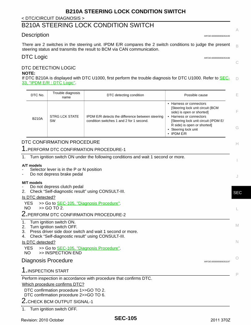
B210A STEERING LOCK CONDITION SWITCH
C
D
E
F
G
H
I
J
L
M
A
B
EC
N
O
P
< DTC/CIRCUIT DIAGNOSIS >
S
B210A STEERING LOCK CONDITION SWITCH
Description INFOID:0000000006353195
There are 2 switches in the steering unit. IPDM E/R compares the 2 switch conditions to judge the presentsteering status and transmits the result to BCM via CAN communication.
DTC Logic INFOID:0000000006353196
DTC DETECTION LOGICNOTE:If DTC B210A is displayed with DTC U1000, first perform the trouble diagnosis for DTC U1000. Refer to SEC-33, "IPDM E/R : DTC Logic".
DTC CONFIRMATION PROCEDURE
1.PERFORM DTC CONFIRMATION PROCEDURE-1
1. Turn ignition switch ON under the following conditions and wait 1 second or more.
A/T models- Selector lever is in the P or N position- Do not depress brake pedal
M/T models- Do not depress clutch pedal2. Check “Self-diagnostic result” using CONSULT-III.Is DTC detected?YES >> Go to SEC-105, "Diagnosis Procedure".NO >> GO TO 2.
2.PERFORM DTC CONFIRMATION PROCEDURE-2
1. Turn ignition switch ON.2. Turn ignition switch OFF.3. Press driver side door switch and wait 1 second or more.4. Check “Self-diagnostic result” using CONSULT-III.Is DTC detected?YES >> Go to SEC-105, "Diagnosis Procedure".NO >> INSPECTION END
Diagnosis Procedure INFOID:0000000006353197
1.INSPECTION START
Perform inspection in accordance with procedure that confirms DTC.Which procedure confirms DTC?DTC confirmation procedure 1>>GO TO 2.DTC confirmation procedure 2>>GO TO 6.
2.CHECK BCM OUTPUT SIGNAL-1
1. Turn ignition switch OFF.
DTC No.Trouble diagnosis
nameDTC detecting condition Possible cause
B210ASTRG LCK STATE SW
IPDM E/R detects the difference between steering condition switches 1 and 2 for 1 second.
• Harness or connectors[Steering lock unit circuit (BCM side) is open or shorted]
• Harness or connectors[Steering lock unit circuit (IPDM E/R side) is open or shorted]
• Steering lock unit • IPDM E/R
SEC-105Revision: 2010 October 2011 370Z
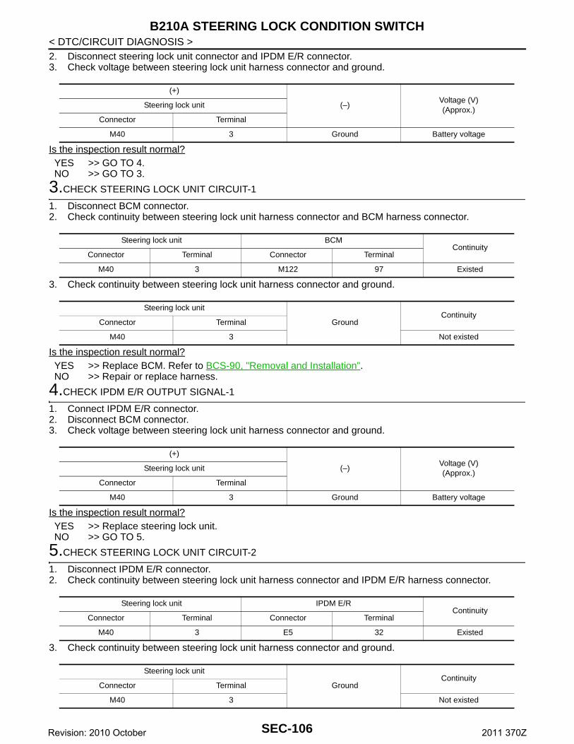
B210A STEERING LOCK CONDITION SWITCH
< DTC/CIRCUIT DIAGNOSIS >2. Disconnect steering lock unit connector and IPDM E/R connector.3. Check voltage between steering lock unit harness connector and ground.Is the inspection result normal?YES >> GO TO 4.NO >> GO TO 3.
3.CHECK STEERING LOCK UNIT CIRCUIT-1
1. Disconnect BCM connector.2. Check continuity between steering lock unit harness connector and BCM harness connector.
3. Check continuity between steering lock unit harness connector and ground.
Is the inspection result normal?YES >> Replace BCM. Refer to BCS-90, "Removal and Installation".NO >> Repair or replace harness.
4.CHECK IPDM E/R OUTPUT SIGNAL-1
1. Connect IPDM E/R connector.2. Disconnect BCM connector.3. Check voltage between steering lock unit harness connector and ground.
Is the inspection result normal?YES >> Replace steering lock unit.NO >> GO TO 5.
5.CHECK STEERING LOCK UNIT CIRCUIT-2
1. Disconnect IPDM E/R connector.2. Check continuity between steering lock unit harness connector and IPDM E/R harness connector.
3. Check continuity between steering lock unit harness connector and ground.
(+)
(–)Voltage (V)(Approx.)
Steering lock unit
Connector Terminal
M40 3 Ground Battery voltage
Steering lock unit BCMContinuity
Connector Terminal Connector Terminal
M40 3 M122 97 Existed
Steering lock unit
GroundContinuity
Connector Terminal
M40 3 Not existed
(+)
(–)Voltage (V)(Approx.)
Steering lock unit
Connector Terminal
M40 3 Ground Battery voltage
Steering lock unit IPDM E/RContinuity
Connector Terminal Connector Terminal
M40 3 E5 32 Existed
Steering lock unit
GroundContinuity
Connector Terminal
M40 3 Not existed
SEC-106Revision: 2010 October 2011 370Z
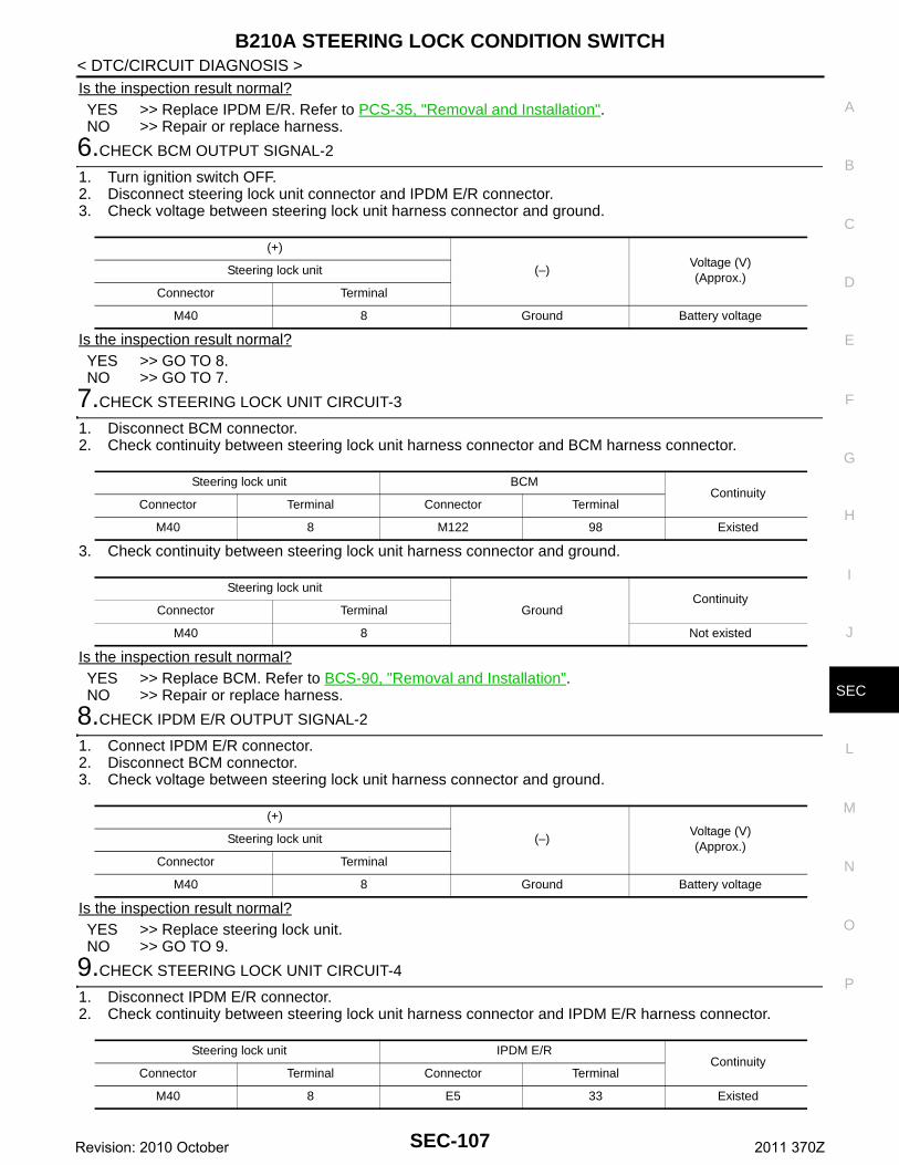
B210A STEERING LOCK CONDITION SWITCH
C
D
E
F
G
H
I
J
L
M
A
B
EC
N
O
P
< DTC/CIRCUIT DIAGNOSIS >
S
Is the inspection result normal?YES >> Replace IPDM E/R. Refer to PCS-35, "Removal and Installation".NO >> Repair or replace harness.
6.CHECK BCM OUTPUT SIGNAL-2
1. Turn ignition switch OFF.2. Disconnect steering lock unit connector and IPDM E/R connector.3. Check voltage between steering lock unit harness connector and ground.
Is the inspection result normal?YES >> GO TO 8.NO >> GO TO 7.
7.CHECK STEERING LOCK UNIT CIRCUIT-3
1. Disconnect BCM connector.2. Check continuity between steering lock unit harness connector and BCM harness connector.
3. Check continuity between steering lock unit harness connector and ground.
Is the inspection result normal?YES >> Replace BCM. Refer to BCS-90, "Removal and Installation".NO >> Repair or replace harness.
8.CHECK IPDM E/R OUTPUT SIGNAL-2
1. Connect IPDM E/R connector.2. Disconnect BCM connector.3. Check voltage between steering lock unit harness connector and ground.
Is the inspection result normal?YES >> Replace steering lock unit.NO >> GO TO 9.
9.CHECK STEERING LOCK UNIT CIRCUIT-4
1. Disconnect IPDM E/R connector.2. Check continuity between steering lock unit harness connector and IPDM E/R harness connector.
(+)
(–)Voltage (V)(Approx.)
Steering lock unit
Connector Terminal
M40 8 Ground Battery voltage
Steering lock unit BCMContinuity
Connector Terminal Connector Terminal
M40 8 M122 98 Existed
Steering lock unit
GroundContinuity
Connector Terminal
M40 8 Not existed
(+)
(–)Voltage (V)(Approx.)
Steering lock unit
Connector Terminal
M40 8 Ground Battery voltage
Steering lock unit IPDM E/RContinuity
Connector Terminal Connector Terminal
M40 8 E5 33 Existed
SEC-107Revision: 2010 October 2011 370Z
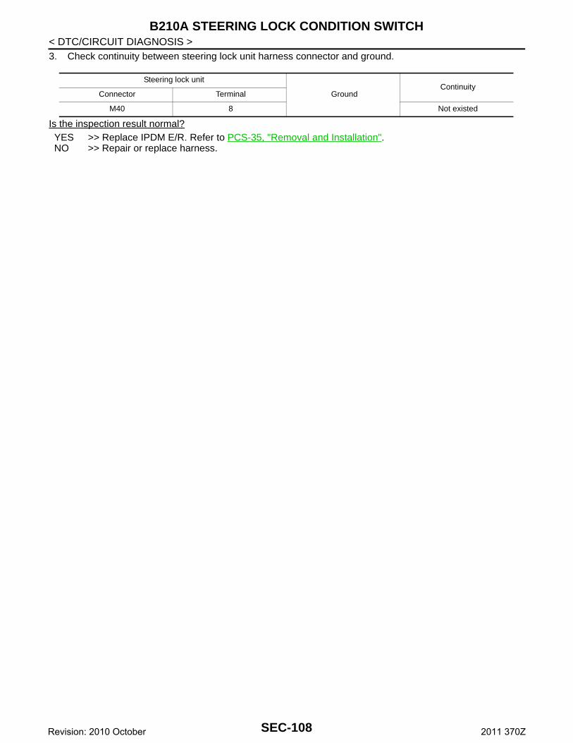
B210A STEERING LOCK CONDITION SWITCH
< DTC/CIRCUIT DIAGNOSIS >3. Check continuity between steering lock unit harness connector and ground.Is the inspection result normal?YES >> Replace IPDM E/R. Refer to PCS-35, "Removal and Installation".NO >> Repair or replace harness.
Steering lock unit
GroundContinuity
Connector Terminal
M40 8 Not existed
SEC-108Revision: 2010 October 2011 370Z
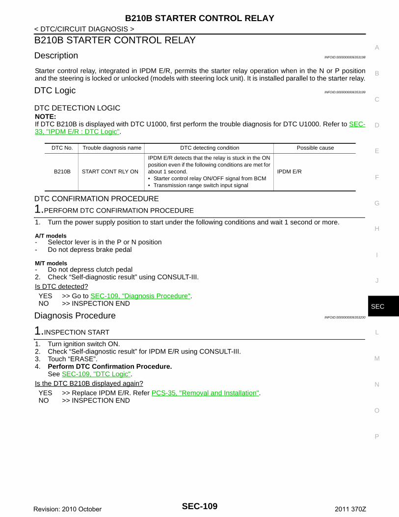
B210B STARTER CONTROL RELAY
C
D
E
F
G
H
I
J
L
M
A
B
EC
N
O
P
< DTC/CIRCUIT DIAGNOSIS >
S
B210B STARTER CONTROL RELAY
Description INFOID:0000000006353198
Starter control relay, integrated in IPDM E/R, permits the starter relay operation when in the N or P positionand the steering is locked or unlocked (models with steering lock unit). It is installed parallel to the starter relay.
DTC Logic INFOID:0000000006353199
DTC DETECTION LOGICNOTE:If DTC B210B is displayed with DTC U1000, first perform the trouble diagnosis for DTC U1000. Refer to SEC-33, "IPDM E/R : DTC Logic".
DTC CONFIRMATION PROCEDURE
1.PERFORM DTC CONFIRMATION PROCEDURE
1. Turn the power supply position to start under the following conditions and wait 1 second or more.
A/T models- Selector lever is in the P or N position- Do not depress brake pedal
M/T models- Do not depress clutch pedal2. Check “Self-diagnostic result” using CONSULT-III.Is DTC detected?YES >> Go to SEC-109, "Diagnosis Procedure".NO >> INSPECTION END
Diagnosis Procedure INFOID:0000000006353200
1.INSPECTION START
1. Turn ignition switch ON.2. Check “Self-diagnostic result” for IPDM E/R using CONSULT-III.3. Touch “ERASE”.4. Perform DTC Confirmation Procedure.
See SEC-109, "DTC Logic".Is the DTC B210B displayed again?YES >> Replace IPDM E/R. Refer PCS-35, "Removal and Installation".NO >> INSPECTION END
DTC No. Trouble diagnosis name DTC detecting condition Possible cause
B210B START CONT RLY ON
IPDM E/R detects that the relay is stuck in the ON position even if the following conditions are met for about 1 second.• Starter control relay ON/OFF signal from BCM• Transmission range switch input signal
IPDM E/R
SEC-109Revision: 2010 October 2011 370Z
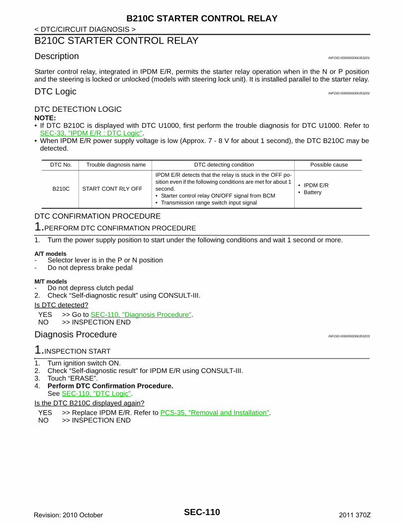
B210C STARTER CONTROL RELAY
< DTC/CIRCUIT DIAGNOSIS >B210C STARTER CONTROL RELAY
Description INFOID:0000000006353201
Starter control relay, integrated in IPDM E/R, permits the starter relay operation when in the N or P positionand the steering is locked or unlocked (models with steering lock unit). It is installed parallel to the starter relay.
DTC Logic INFOID:0000000006353202
DTC DETECTION LOGICNOTE:• If DTC B210C is displayed with DTC U1000, first perform the trouble diagnosis for DTC U1000. Refer to
SEC-33, "IPDM E/R : DTC Logic".• When IPDM E/R power supply voltage is low (Approx. 7 - 8 V for about 1 second), the DTC B210C may be
detected.
DTC CONFIRMATION PROCEDURE
1.PERFORM DTC CONFIRMATION PROCEDURE
1. Turn the power supply position to start under the following conditions and wait 1 second or more.
A/T models- Selector lever is in the P or N position- Do not depress brake pedal
M/T models- Do not depress clutch pedal2. Check “Self-diagnostic result” using CONSULT-III.Is DTC detected?YES >> Go to SEC-110, "Diagnosis Procedure".NO >> INSPECTION END
Diagnosis Procedure INFOID:0000000006353203
1.INSPECTION START
1. Turn ignition switch ON.2. Check “Self-diagnostic result” for IPDM E/R using CONSULT-III.3. Touch “ERASE”.4. Perform DTC Confirmation Procedure.
See SEC-110, "DTC Logic".Is the DTC B210C displayed again?YES >> Replace IPDM E/R. Refer to PCS-35, "Removal and Installation".NO >> INSPECTION END
DTC No. Trouble diagnosis name DTC detecting condition Possible cause
B210C START CONT RLY OFF
IPDM E/R detects that the relay is stuck in the OFF po-sition even if the following conditions are met for about 1 second.• Starter control relay ON/OFF signal from BCM• Transmission range switch input signal
• IPDM E/R• Battery
SEC-110Revision: 2010 October 2011 370Z
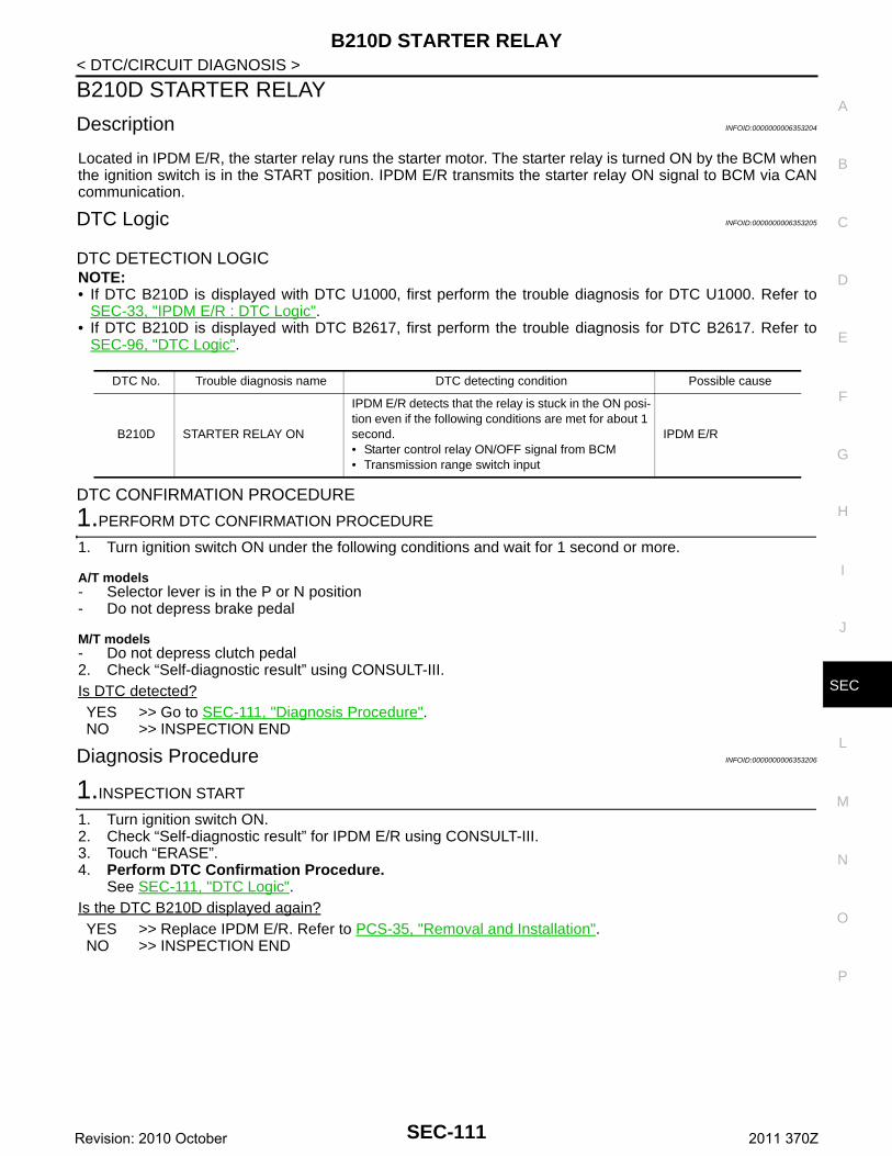
B210D STARTER RELAY
C
D
E
F
G
H
I
J
L
M
A
B
EC
N
O
P
< DTC/CIRCUIT DIAGNOSIS >
S
B210D STARTER RELAY
Description INFOID:0000000006353204
Located in IPDM E/R, the starter relay runs the starter motor. The starter relay is turned ON by the BCM whenthe ignition switch is in the START position. IPDM E/R transmits the starter relay ON signal to BCM via CANcommunication.
DTC Logic INFOID:0000000006353205
DTC DETECTION LOGICNOTE:• If DTC B210D is displayed with DTC U1000, first perform the trouble diagnosis for DTC U1000. Refer to
SEC-33, "IPDM E/R : DTC Logic".• If DTC B210D is displayed with DTC B2617, first perform the trouble diagnosis for DTC B2617. Refer to
SEC-96, "DTC Logic".
DTC CONFIRMATION PROCEDURE
1.PERFORM DTC CONFIRMATION PROCEDURE
1. Turn ignition switch ON under the following conditions and wait for 1 second or more.
A/T models- Selector lever is in the P or N position- Do not depress brake pedal
M/T models- Do not depress clutch pedal2. Check “Self-diagnostic result” using CONSULT-III.Is DTC detected?YES >> Go to SEC-111, "Diagnosis Procedure".NO >> INSPECTION END
Diagnosis Procedure INFOID:0000000006353206
1.INSPECTION START
1. Turn ignition switch ON.2. Check “Self-diagnostic result” for IPDM E/R using CONSULT-III.3. Touch “ERASE”.4. Perform DTC Confirmation Procedure.
See SEC-111, "DTC Logic".Is the DTC B210D displayed again?YES >> Replace IPDM E/R. Refer to PCS-35, "Removal and Installation".NO >> INSPECTION END
DTC No. Trouble diagnosis name DTC detecting condition Possible cause
B210D STARTER RELAY ON
IPDM E/R detects that the relay is stuck in the ON posi-tion even if the following conditions are met for about 1 second.• Starter control relay ON/OFF signal from BCM• Transmission range switch input
IPDM E/R
SEC-111Revision: 2010 October 2011 370Z
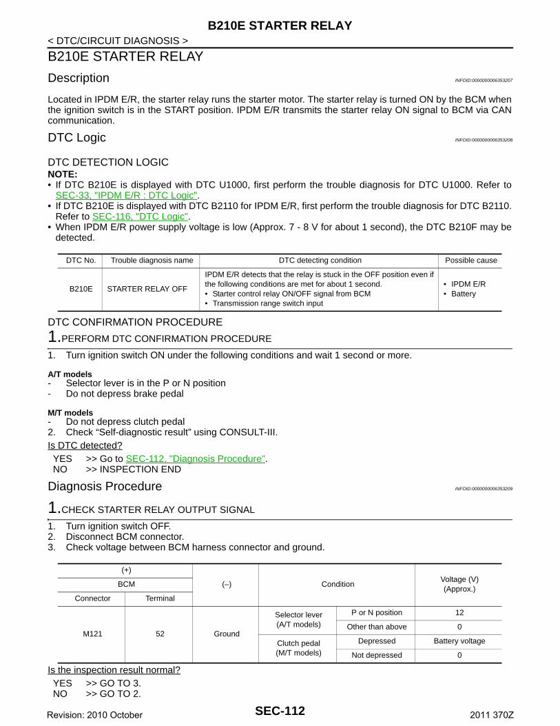
B210E STARTER RELAY
< DTC/CIRCUIT DIAGNOSIS >B210E STARTER RELAY
Description INFOID:0000000006353207
Located in IPDM E/R, the starter relay runs the starter motor. The starter relay is turned ON by the BCM whenthe ignition switch is in the START position. IPDM E/R transmits the starter relay ON signal to BCM via CANcommunication.
DTC Logic INFOID:0000000006353208
DTC DETECTION LOGICNOTE:• If DTC B210E is displayed with DTC U1000, first perform the trouble diagnosis for DTC U1000. Refer to
SEC-33, "IPDM E/R : DTC Logic".• If DTC B210E is displayed with DTC B2110 for IPDM E/R, first perform the trouble diagnosis for DTC B2110.
Refer to SEC-116, "DTC Logic".• When IPDM E/R power supply voltage is low (Approx. 7 - 8 V for about 1 second), the DTC B210F may be
detected.
DTC CONFIRMATION PROCEDURE
1.PERFORM DTC CONFIRMATION PROCEDURE
1. Turn ignition switch ON under the following conditions and wait 1 second or more.
A/T models- Selector lever is in the P or N position- Do not depress brake pedal
M/T models- Do not depress clutch pedal2. Check “Self-diagnostic result” using CONSULT-III.Is DTC detected?YES >> Go to SEC-112, "Diagnosis Procedure".NO >> INSPECTION END
Diagnosis Procedure INFOID:0000000006353209
1.CHECK STARTER RELAY OUTPUT SIGNAL
1. Turn ignition switch OFF.2. Disconnect BCM connector.3. Check voltage between BCM harness connector and ground.
Is the inspection result normal?YES >> GO TO 3.NO >> GO TO 2.
DTC No. Trouble diagnosis name DTC detecting condition Possible cause
B210E STARTER RELAY OFF
IPDM E/R detects that the relay is stuck in the OFF position even if the following conditions are met for about 1 second.• Starter control relay ON/OFF signal from BCM• Transmission range switch input
• IPDM E/R• Battery
(+)
(–) ConditionVoltage (V)(Approx.)
BCM
Connector Terminal
M121 52 Ground
Selector lever(A/T models)
P or N position 12
Other than above 0
Clutch pedal(M/T models)
Depressed Battery voltage
Not depressed 0
SEC-112Revision: 2010 October 2011 370Z
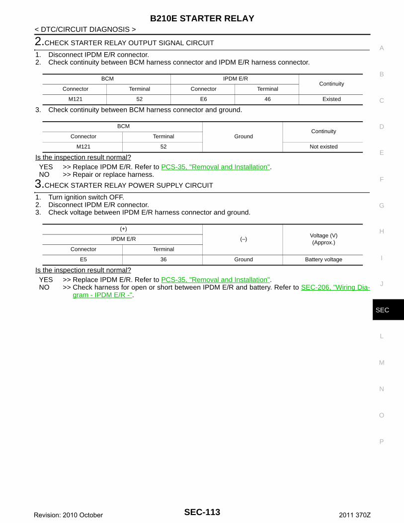
B210E STARTER RELAY
C
D
E
F
G
H
I
J
L
M
A
B
EC
N
O
P
< DTC/CIRCUIT DIAGNOSIS >
S
2.CHECK STARTER RELAY OUTPUT SIGNAL CIRCUIT
1. Disconnect IPDM E/R connector.2. Check continuity between BCM harness connector and IPDM E/R harness connector.
3. Check continuity between BCM harness connector and ground.
Is the inspection result normal?YES >> Replace IPDM E/R. Refer to PCS-35, "Removal and Installation".NO >> Repair or replace harness.
3.CHECK STARTER RELAY POWER SUPPLY CIRCUIT
1. Turn ignition switch OFF.2. Disconnect IPDM E/R connector.3. Check voltage between IPDM E/R harness connector and ground.
Is the inspection result normal?YES >> Replace IPDM E/R. Refer to PCS-35, "Removal and Installation".NO >> Check harness for open or short between IPDM E/R and battery. Refer to SEC-206, "Wiring Dia-
gram - IPDM E/R -".
BCM IPDM E/RContinuity
Connector Terminal Connector Terminal
M121 52 E6 46 Existed
BCM
GroundContinuity
Connector Terminal
M121 52 Not existed
(+)
(–)Voltage (V)(Approx.)
IPDM E/R
Connector Terminal
E5 36 Ground Battery voltage
SEC-113Revision: 2010 October 2011 370Z
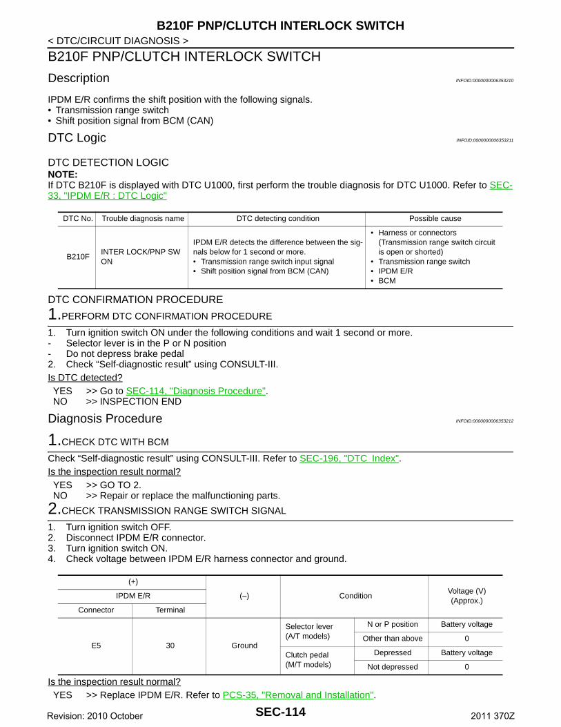
B210F PNP/CLUTCH INTERLOCK SWITCH
< DTC/CIRCUIT DIAGNOSIS >B210F PNP/CLUTCH INTERLOCK SWITCH
Description INFOID:0000000006353210
IPDM E/R confirms the shift position with the following signals.• Transmission range switch• Shift position signal from BCM (CAN)
DTC Logic INFOID:0000000006353211
DTC DETECTION LOGICNOTE:If DTC B210F is displayed with DTC U1000, first perform the trouble diagnosis for DTC U1000. Refer to SEC-33, "IPDM E/R : DTC Logic"
DTC CONFIRMATION PROCEDURE
1.PERFORM DTC CONFIRMATION PROCEDURE
1. Turn ignition switch ON under the following conditions and wait 1 second or more.- Selector lever is in the P or N position- Do not depress brake pedal2. Check “Self-diagnostic result” using CONSULT-III.Is DTC detected?YES >> Go to SEC-114, "Diagnosis Procedure".NO >> INSPECTION END
Diagnosis Procedure INFOID:0000000006353212
1.CHECK DTC WITH BCM
Check “Self-diagnostic result” using CONSULT-III. Refer to SEC-196, "DTC Index".Is the inspection result normal?YES >> GO TO 2.NO >> Repair or replace the malfunctioning parts.
2.CHECK TRANSMISSION RANGE SWITCH SIGNAL
1. Turn ignition switch OFF.2. Disconnect IPDM E/R connector.3. Turn ignition switch ON.4. Check voltage between IPDM E/R harness connector and ground.
Is the inspection result normal?YES >> Replace IPDM E/R. Refer to PCS-35, "Removal and Installation".
DTC No. Trouble diagnosis name DTC detecting condition Possible cause
B210FINTER LOCK/PNP SW ON
IPDM E/R detects the difference between the sig-nals below for 1 second or more.• Transmission range switch input signal• Shift position signal from BCM (CAN)
• Harness or connectors(Transmission range switch circuit is open or shorted)
• Transmission range switch• IPDM E/R• BCM
(+)
(–) ConditionVoltage (V)(Approx.)
IPDM E/R
Connector Terminal
E5 30 Ground
Selector lever(A/T models)
N or P position Battery voltage
Other than above 0
Clutch pedal(M/T models)
Depressed Battery voltage
Not depressed 0
SEC-114Revision: 2010 October 2011 370Z
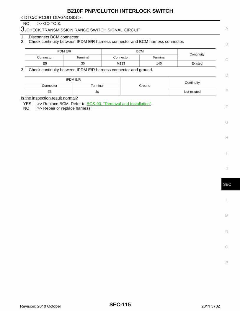
B210F PNP/CLUTCH INTERLOCK SWITCH
C
D
E
F
G
H
I
J
L
M
A
B
EC
N
O
P
< DTC/CIRCUIT DIAGNOSIS >
S
NO >> GO TO 3.
3.CHECK TRANSMISSION RANGE SWITCH SIGNAL CIRCUIT
1. Disconnect BCM connector.2. Check continuity between IPDM E/R harness connector and BCM harness connector.
3. Check continuity between IPDM E/R harness connector and ground.
Is the inspection result normal?YES >> Replace BCM. Refer to BCS-90, "Removal and Installation".NO >> Repair or replace harness.
IPDM E/R BCM Continuity
Connector Terminal Connector Terminal
E5 30 M123 140 Existed
IPDM E/R
GroundContinuity
Connector Terminal
E5 30 Not existed
SEC-115Revision: 2010 October 2011 370Z
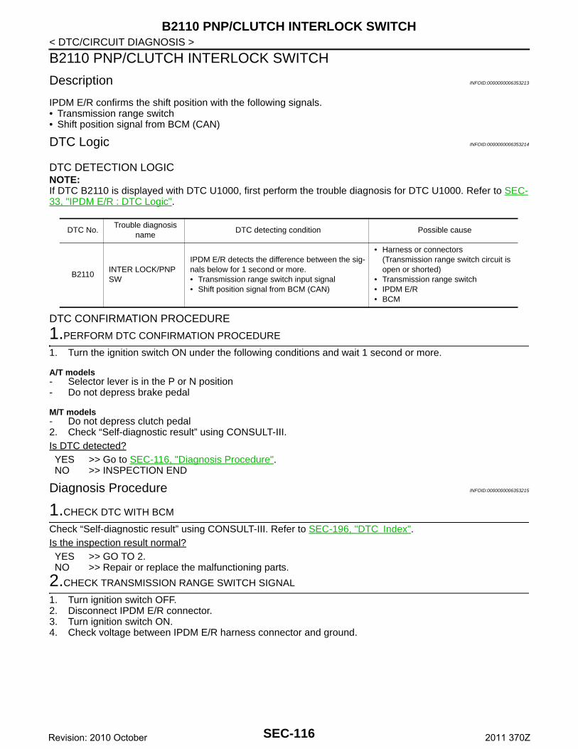
B2110 PNP/CLUTCH INTERLOCK SWITCH
< DTC/CIRCUIT DIAGNOSIS >B2110 PNP/CLUTCH INTERLOCK SWITCH
Description INFOID:0000000006353213
IPDM E/R confirms the shift position with the following signals.• Transmission range switch• Shift position signal from BCM (CAN)
DTC Logic INFOID:0000000006353214
DTC DETECTION LOGICNOTE:If DTC B2110 is displayed with DTC U1000, first perform the trouble diagnosis for DTC U1000. Refer to SEC-33, "IPDM E/R : DTC Logic".
DTC CONFIRMATION PROCEDURE
1.PERFORM DTC CONFIRMATION PROCEDURE
1. Turn the ignition switch ON under the following conditions and wait 1 second or more.
A/T models- Selector lever is in the P or N position- Do not depress brake pedal
M/T models- Do not depress clutch pedal2. Check “Self-diagnostic result” using CONSULT-III.Is DTC detected?YES >> Go to SEC-116, "Diagnosis Procedure".NO >> INSPECTION END
Diagnosis Procedure INFOID:0000000006353215
1.CHECK DTC WITH BCM
Check “Self-diagnostic result” using CONSULT-III. Refer to SEC-196, "DTC Index".Is the inspection result normal?YES >> GO TO 2.NO >> Repair or replace the malfunctioning parts.
2.CHECK TRANSMISSION RANGE SWITCH SIGNAL
1. Turn ignition switch OFF.2. Disconnect IPDM E/R connector.3. Turn ignition switch ON.4. Check voltage between IPDM E/R harness connector and ground.
DTC No.Trouble diagnosis
nameDTC detecting condition Possible cause
B2110INTER LOCK/PNP SW
IPDM E/R detects the difference between the sig-nals below for 1 second or more.• Transmission range switch input signal• Shift position signal from BCM (CAN)
• Harness or connectors(Transmission range switch circuit is open or shorted)
• Transmission range switch• IPDM E/R• BCM
SEC-116Revision: 2010 October 2011 370Z
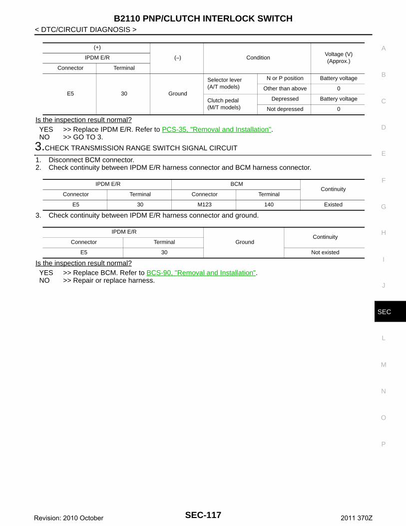
B2110 PNP/CLUTCH INTERLOCK SWITCH
C
D
E
F
G
H
I
J
L
M
A
B
EC
N
O
P
< DTC/CIRCUIT DIAGNOSIS >
S
Is the inspection result normal?YES >> Replace IPDM E/R. Refer to PCS-35, "Removal and Installation".NO >> GO TO 3.
3.CHECK TRANSMISSION RANGE SWITCH SIGNAL CIRCUIT
1. Disconnect BCM connector.2. Check continuity between IPDM E/R harness connector and BCM harness connector.
3. Check continuity between IPDM E/R harness connector and ground.
Is the inspection result normal?YES >> Replace BCM. Refer to BCS-90, "Removal and Installation".NO >> Repair or replace harness.
(+)
(–) ConditionVoltage (V)(Approx.)
IPDM E/R
Connector Terminal
E5 30 Ground
Selector lever(A/T models)
N or P position Battery voltage
Other than above 0
Clutch pedal(M/T models)
Depressed Battery voltage
Not depressed 0
IPDM E/R BCM Continuity
Connector Terminal Connector Terminal
E5 30 M123 140 Existed
IPDM E/R
GroundContinuity
Connector Terminal
E5 30 Not existed
SEC-117Revision: 2010 October 2011 370Z
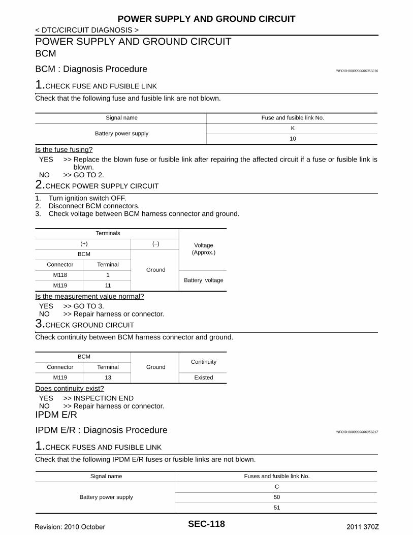
POWER SUPPLY AND GROUND CIRCUIT
< DTC/CIRCUIT DIAGNOSIS >POWER SUPPLY AND GROUND CIRCUITBCM
BCM : Diagnosis Procedure INFOID:0000000006353216
1.CHECK FUSE AND FUSIBLE LINK
Check that the following fuse and fusible link are not blown.
Is the fuse fusing?YES >> Replace the blown fuse or fusible link after repairing the affected circuit if a fuse or fusible link is
blown.NO >> GO TO 2.
2.CHECK POWER SUPPLY CIRCUIT
1. Turn ignition switch OFF.2. Disconnect BCM connectors.3. Check voltage between BCM harness connector and ground.
Is the measurement value normal?YES >> GO TO 3.NO >> Repair harness or connector.
3.CHECK GROUND CIRCUIT
Check continuity between BCM harness connector and ground.
Does continuity exist?YES >> INSPECTION ENDNO >> Repair harness or connector.
IPDM E/R
IPDM E/R : Diagnosis Procedure INFOID:0000000006353217
1.CHECK FUSES AND FUSIBLE LINK
Check that the following IPDM E/R fuses or fusible links are not blown.
Signal name Fuse and fusible link No.
Battery power supplyK
10
Terminals
Voltage(Approx.)
(+) (−)
BCM
GroundConnector Terminal
M118 1Battery voltage
M119 11
BCM
GroundContinuity
Connector Terminal
M119 13 Existed
Signal name Fuses and fusible link No.
Battery power supply
C
50
51
SEC-118Revision: 2010 October 2011 370Z
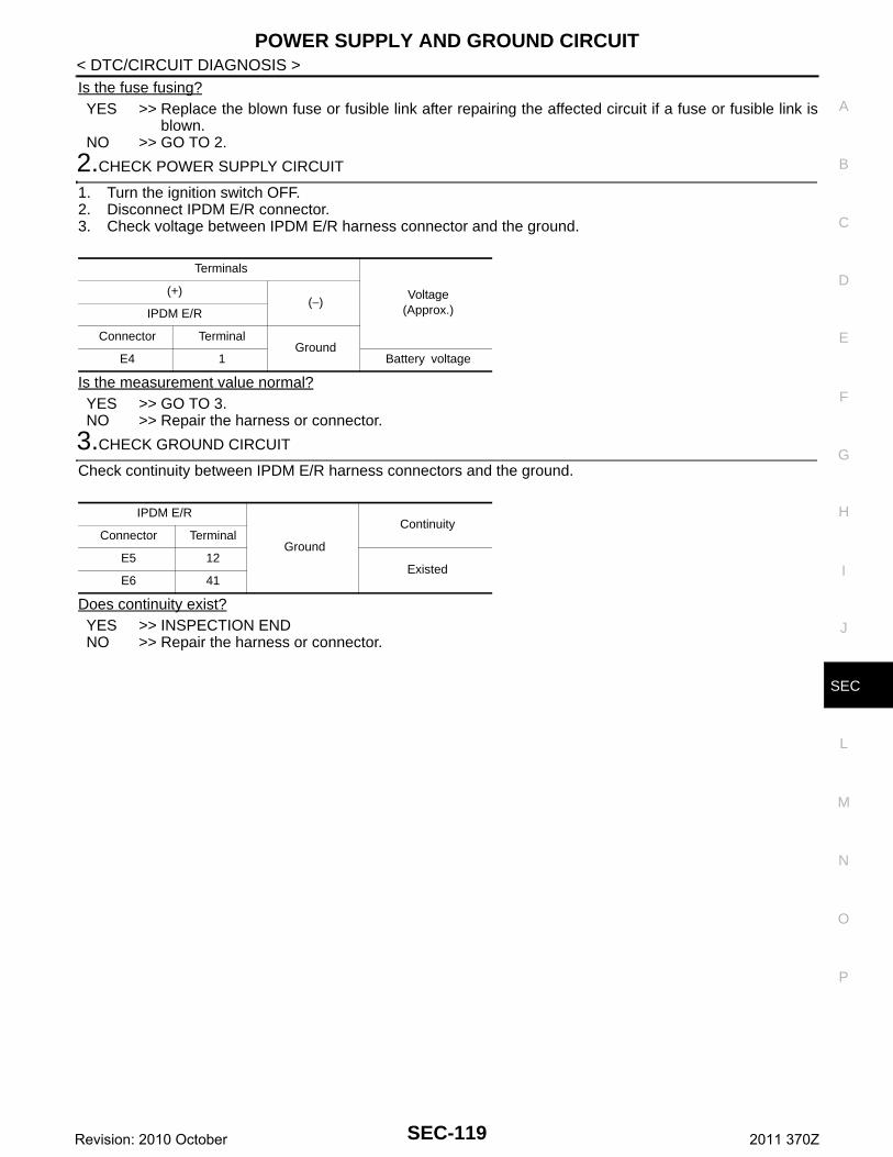
POWER SUPPLY AND GROUND CIRCUIT
C
D
E
F
G
H
I
J
L
M
A
B
EC
N
O
P
< DTC/CIRCUIT DIAGNOSIS >
S
Is the fuse fusing?YES >> Replace the blown fuse or fusible link after repairing the affected circuit if a fuse or fusible link is
blown.NO >> GO TO 2.
2.CHECK POWER SUPPLY CIRCUIT
1. Turn the ignition switch OFF.2. Disconnect IPDM E/R connector.3. Check voltage between IPDM E/R harness connector and the ground.
Is the measurement value normal?YES >> GO TO 3.NO >> Repair the harness or connector.
3.CHECK GROUND CIRCUIT
Check continuity between IPDM E/R harness connectors and the ground.
Does continuity exist?YES >> INSPECTION ENDNO >> Repair the harness or connector.
Terminals
Voltage(Approx.)
(+)(−)
IPDM E/R
Connector TerminalGround
E4 1 Battery voltage
IPDM E/R
Ground
ContinuityConnector Terminal
E5 12Existed
E6 41
SEC-119Revision: 2010 October 2011 370Z
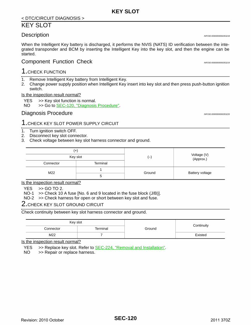
KEY SLOT
< DTC/CIRCUIT DIAGNOSIS >KEY SLOT
Description INFOID:0000000006353218
When the Intelligent Key battery is discharged, it performs the NVIS (NATS) ID verification between the inte-grated transponder and BCM by inserting the Intelligent Key into the key slot, and then the engine can bestarted.
Component Function Check INFOID:0000000006353219
1.CHECK FUNCTION
1. Remove Intelligent Key battery from Intelligent Key.2. Change power supply position when Intelligent Key insert into key slot and then press push-button ignition
switch.Is the inspection result normal?YES >> Key slot function is normal.NO >> Go to SEC-120, "Diagnosis Procedure".
Diagnosis Procedure INFOID:0000000006353220
1.CHECK KEY SLOT POWER SUPPLY CIRCUIT
1. Turn ignition switch OFF.2. Disconnect key slot connector.3. Check voltage between key slot harness connector and ground.
Is the inspection result normal?YES >> GO TO 2.NO-1 >> Check 10 A fuse [No. 6 and 9 located in the fuse block (J/B)].NO-2 >> Check harness for open or short between key slot and fuse.
2.CHECK KEY SLOT GROUND CIRCUIT
Check continuity between key slot harness connector and ground.
Is the inspection result normal?YES >> Replace key slot. Refer to SEC-224, "Removal and Installation".NO >> Repair or replace harness.
(+)
(–)Voltage (V)(Approx.)
Key slot
Connector Terminal
M221
Ground Battery voltage5
Key slot
GroundContinuity
Connector Terminal
M22 7 Existed
SEC-120Revision: 2010 October 2011 370Z
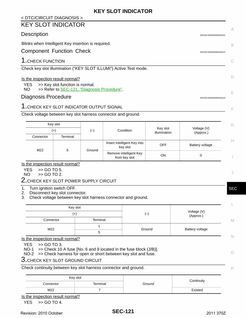
KEY SLOT INDICATOR
C
D
E
F
G
H
I
J
L
M
A
B
EC
N
O
P
< DTC/CIRCUIT DIAGNOSIS >
S
KEY SLOT INDICATOR
Description INFOID:0000000006353221
Blinks when Intelligent Key insertion is required.
Component Function Check INFOID:0000000006353222
1.CHECK FUNCTION
Check key slot illumination (“KEY SLOT ILLUMI”) Active Test mode.
Is the inspection result normal?YES >> Key slot function is normal.NO >> Refer to SEC-121, "Diagnosis Procedure".
Diagnosis Procedure INFOID:0000000006353223
1.CHECK KEY SLOT INDICATOR OUTPUT SIGNAL
Check voltage between key slot harness connector and ground.
Is the inspection result normal?YES >> GO TO 5.NO >> GO TO 2.
2.CHECK KEY SLOT POWER SUPPLY CIRCUIT
1. Turn ignition switch OFF.2. Disconnect key slot connector.3. Check voltage between key slot harness connector and ground.
Is the inspection result normal?YES >> GO TO 3.NO-1 >> Check 10 A fuse [No. 6 and 9 located in the fuse block (J/B)].NO-2 >> Check harness for open or short between key slot and fuse.
3.CHECK KEY SLOT GROUND CIRCUIT
Check continuity between key slot harness connector and ground.
Is the inspection result normal?YES >> GO TO 4.
Key slot
(–) ConditionKey slot
illuminationVoltage (V) (Approx.)
(+)
Connector Terminal
M22 6 Ground
Insert Intelligent Key into key slot
OFF Battery voltage
Remove Intelligent Key from key slot
ON 0
Key slot
(–)Voltage (V)(Approx.)
(+)
Connector Terminal
M221
Ground Battery voltage5
Key slot
GroundContinuity
Connector Terminal
M22 7 Existed
SEC-121Revision: 2010 October 2011 370Z
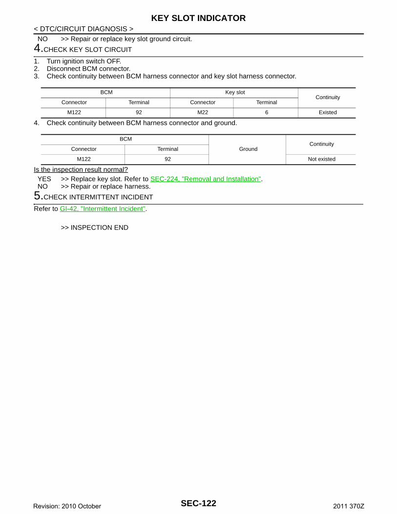
KEY SLOT INDICATOR
< DTC/CIRCUIT DIAGNOSIS >NO >> Repair or replace key slot ground circuit.4.CHECK KEY SLOT CIRCUIT
1. Turn ignition switch OFF.2. Disconnect BCM connector.3. Check continuity between BCM harness connector and key slot harness connector.
4. Check continuity between BCM harness connector and ground.
Is the inspection result normal?YES >> Replace key slot. Refer to SEC-224, "Removal and Installation".NO >> Repair or replace harness.
5.CHECK INTERMITTENT INCIDENT
Refer to GI-42, "Intermittent Incident".
>> INSPECTION END
BCM Key slotContinuity
Connector Terminal Connector Terminal
M122 92 M22 6 Existed
BCM
GroundContinuity
Connector Terminal
M122 92 Not existed
SEC-122Revision: 2010 October 2011 370Z
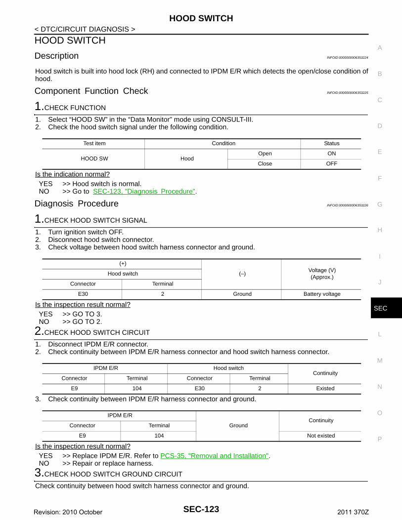
HOOD SWITCH
C
D
E
F
G
H
I
J
L
M
A
B
EC
N
O
P
< DTC/CIRCUIT DIAGNOSIS >
S
HOOD SWITCH
Description INFOID:0000000006353224
Hood switch is built into hood lock (RH) and connected to IPDM E/R which detects the open/close condition ofhood.
Component Function Check INFOID:0000000006353225
1.CHECK FUNCTION
1. Select “HOOD SW” in the “Data Monitor” mode using CONSULT-III. 2. Check the hood switch signal under the following condition.
Is the indication normal?YES >> Hood switch is normal.NO >> Go to SEC-123, "Diagnosis Procedure".
Diagnosis Procedure INFOID:0000000006353226
1.CHECK HOOD SWITCH SIGNAL
1. Turn ignition switch OFF.2. Disconnect hood switch connector.3. Check voltage between hood switch harness connector and ground.
Is the inspection result normal?YES >> GO TO 3.NO >> GO TO 2.
2.CHECK HOOD SWITCH CIRCUIT
1. Disconnect IPDM E/R connector.2. Check continuity between IPDM E/R harness connector and hood switch harness connector.
3. Check continuity between IPDM E/R harness connector and ground.
Is the inspection result normal?YES >> Replace IPDM E/R. Refer to PCS-35, "Removal and Installation".NO >> Repair or replace harness.
3.CHECK HOOD SWITCH GROUND CIRCUIT
Check continuity between hood switch harness connector and ground.
Test item Condition Status
HOOD SW HoodOpen ON
Close OFF
(+)
(–)Voltage (V)(Approx.)
Hood switch
Connector Terminal
E30 2 Ground Battery voltage
IPDM E/R Hood switchContinuity
Connector Terminal Connector Terminal
E9 104 E30 2 Existed
IPDM E/R
GroundContinuity
Connector Terminal
E9 104 Not existed
SEC-123Revision: 2010 October 2011 370Z
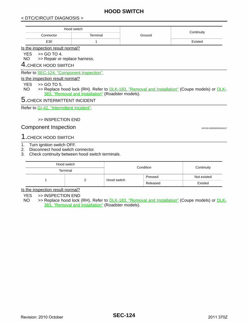
HOOD SWITCH
< DTC/CIRCUIT DIAGNOSIS >Is the inspection result normal?YES >> GO TO 4.NO >> Repair or replace harness.
4.CHECK HOOD SWITCH
Refer to SEC-124, "Component Inspection".Is the inspection result normal?YES >> GO TO 5.NO >> Replace hood lock (RH). Refer to DLK-183, "Removal and Installation" (Coupe models) or DLK-
383, "Removal and Installation" (Roadster models).
5.CHECK INTERMITTENT INCIDENT
Refer to GI-42, "Intermittent Incident".
>> INSPECTION END
Component Inspection INFOID:0000000006353227
1.CHECK HOOD SWITCH
1. Turn ignition switch OFF.2. Disconnect hood switch connector.3. Check continuity between hood switch terminals.
Is the inspection result normal?YES >> INSPECTION ENDNO >> Replace hood lock (RH). Refer to DLK-183, "Removal and Installation" (Coupe models) or DLK-
383, "Removal and Installation" (Roadster models).
Hood switch
GroundContinuity
Connector Terminal
E30 1 Existed
Hood switchCondition Continuity
Terminal
1 2 Hood switchPressed Not existed
Released Existed
SEC-124Revision: 2010 October 2011 370Z
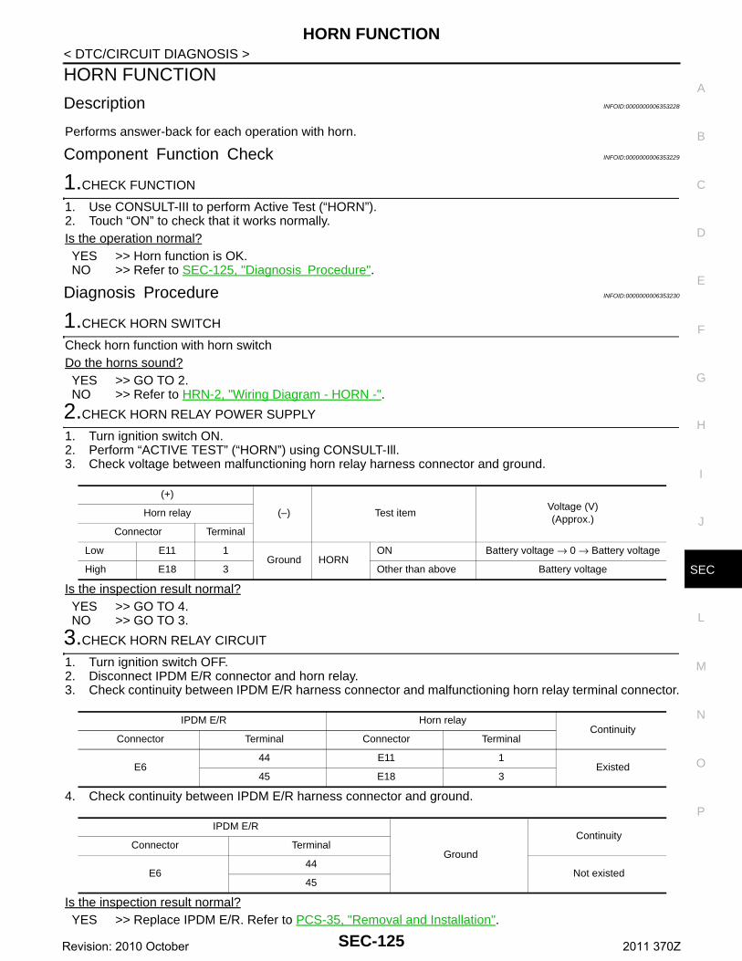
HORN FUNCTION
C
D
E
F
G
H
I
J
L
M
A
B
EC
N
O
P
< DTC/CIRCUIT DIAGNOSIS >
S
HORN FUNCTION
Description INFOID:0000000006353228
Performs answer-back for each operation with horn.
Component Function Check INFOID:0000000006353229
1.CHECK FUNCTION
1. Use CONSULT-III to perform Active Test (“HORN”).2. Touch “ON” to check that it works normally.Is the operation normal?YES >> Horn function is OK.NO >> Refer to SEC-125, "Diagnosis Procedure".
Diagnosis Procedure INFOID:0000000006353230
1.CHECK HORN SWITCH
Check horn function with horn switchDo the horns sound?YES >> GO TO 2.NO >> Refer to HRN-2, "Wiring Diagram - HORN -".
2.CHECK HORN RELAY POWER SUPPLY
1. Turn ignition switch ON.2. Perform “ACTIVE TEST” (“HORN”) using CONSULT-Ill.3. Check voltage between malfunctioning horn relay harness connector and ground.
Is the inspection result normal?YES >> GO TO 4.NO >> GO TO 3.
3.CHECK HORN RELAY CIRCUIT
1. Turn ignition switch OFF.2. Disconnect IPDM E/R connector and horn relay.3. Check continuity between IPDM E/R harness connector and malfunctioning horn relay terminal connector.
4. Check continuity between IPDM E/R harness connector and ground.
Is the inspection result normal?YES >> Replace IPDM E/R. Refer to PCS-35, "Removal and Installation".
(+)
(–) Test itemVoltage (V)(Approx.)
Horn relay
Connector Terminal
Low E11 1Ground HORN
ON Battery voltage → 0 → Battery voltage
High E18 3 Other than above Battery voltage
IPDM E/R Horn relayContinuity
Connector Terminal Connector Terminal
E644 E11 1
Existed45 E18 3
IPDM E/R
Ground
Continuity Connector Terminal
E644
Not existed45
SEC-125Revision: 2010 October 2011 370Z
HORN FUNCTION
< DTC/CIRCUIT DIAGNOSIS >NO >> Repair or replace harness.4.CHECK INTERMITTENT INCIDENT
Refer to GI-42, "Intermittent Incident".Is the inspection result normal?
>> INSPECTION END
SEC-126Revision: 2010 October 2011 370Z
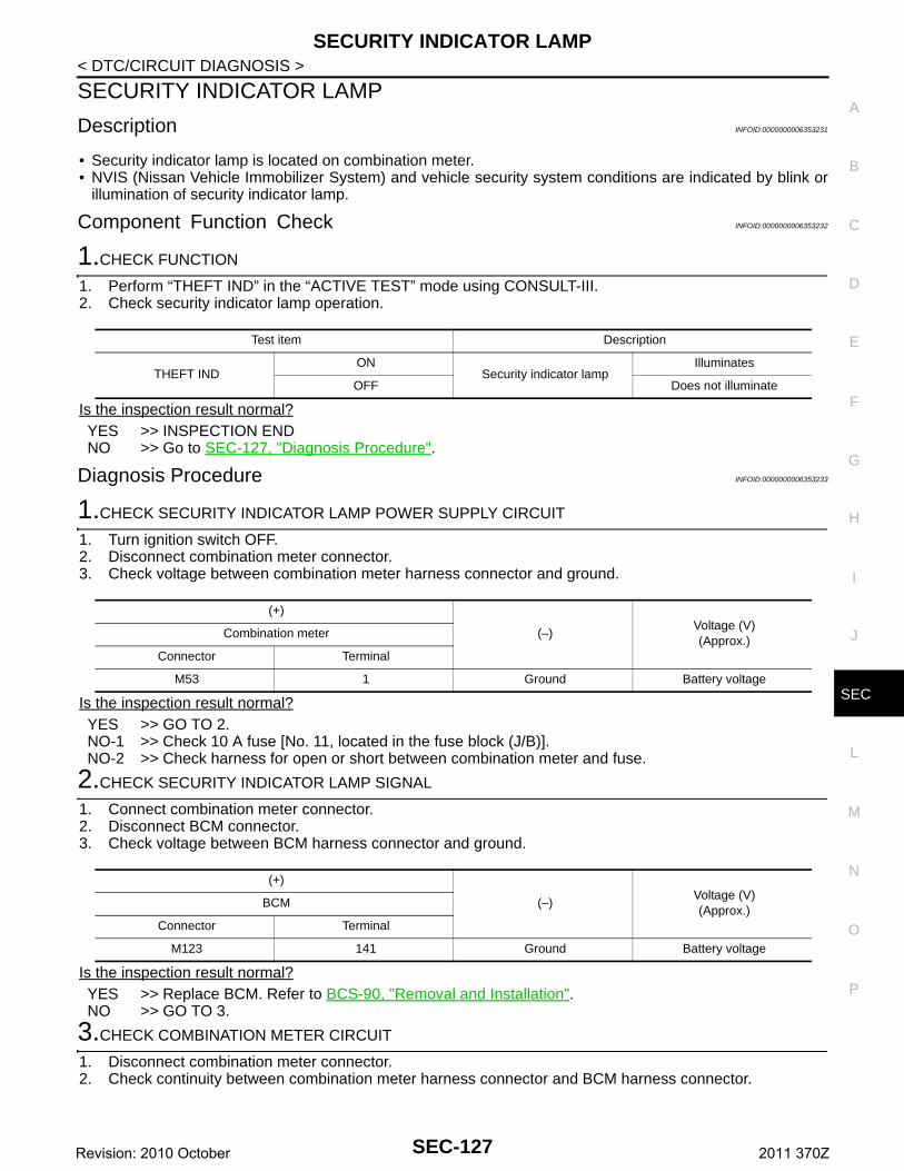
SECURITY INDICATOR LAMP
C
D
E
F
G
H
I
J
L
M
A
B
EC
N
O
P
< DTC/CIRCUIT DIAGNOSIS >
S
SECURITY INDICATOR LAMP
Description INFOID:0000000006353231
• Security indicator lamp is located on combination meter.• NVIS (Nissan Vehicle Immobilizer System) and vehicle security system conditions are indicated by blink or
illumination of security indicator lamp.
Component Function Check INFOID:0000000006353232
1.CHECK FUNCTION
1. Perform “THEFT IND” in the “ACTIVE TEST” mode using CONSULT-III.2. Check security indicator lamp operation.
Is the inspection result normal?YES >> INSPECTION ENDNO >> Go to SEC-127, "Diagnosis Procedure".
Diagnosis Procedure INFOID:0000000006353233
1.CHECK SECURITY INDICATOR LAMP POWER SUPPLY CIRCUIT
1. Turn ignition switch OFF.2. Disconnect combination meter connector.3. Check voltage between combination meter harness connector and ground.
Is the inspection result normal?YES >> GO TO 2.NO-1 >> Check 10 A fuse [No. 11, located in the fuse block (J/B)].NO-2 >> Check harness for open or short between combination meter and fuse.
2.CHECK SECURITY INDICATOR LAMP SIGNAL
1. Connect combination meter connector.2. Disconnect BCM connector.3. Check voltage between BCM harness connector and ground.
Is the inspection result normal?YES >> Replace BCM. Refer to BCS-90, "Removal and Installation".NO >> GO TO 3.
3.CHECK COMBINATION METER CIRCUIT
1. Disconnect combination meter connector.2. Check continuity between combination meter harness connector and BCM harness connector.
Test item Description
THEFT INDON
Security indicator lampIlluminates
OFF Does not illuminate
(+)
(–)Voltage (V)(Approx.)
Combination meter
Connector Terminal
M53 1 Ground Battery voltage
(+)
(–)Voltage (V)(Approx.)
BCM
Connector Terminal
M123 141 Ground Battery voltage
SEC-127Revision: 2010 October 2011 370Z
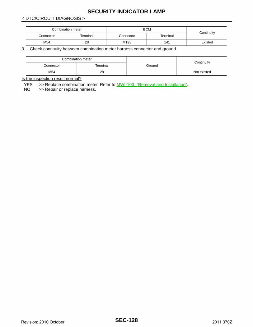
SECURITY INDICATOR LAMP
< DTC/CIRCUIT DIAGNOSIS >3. Check continuity between combination meter harness connector and ground.
Is the inspection result normal?YES >> Replace combination meter. Refer to MWI-103, "Removal and Installation".NO >> Repair or replace harness.
Combination meter BCMContinuity
Connector Terminal Connector Terminal
M54 28 M123 141 Existed
Combination meter
GroundContinuity
Connector Terminal
M54 28 Not existed
SEC-128Revision: 2010 October 2011 370Z
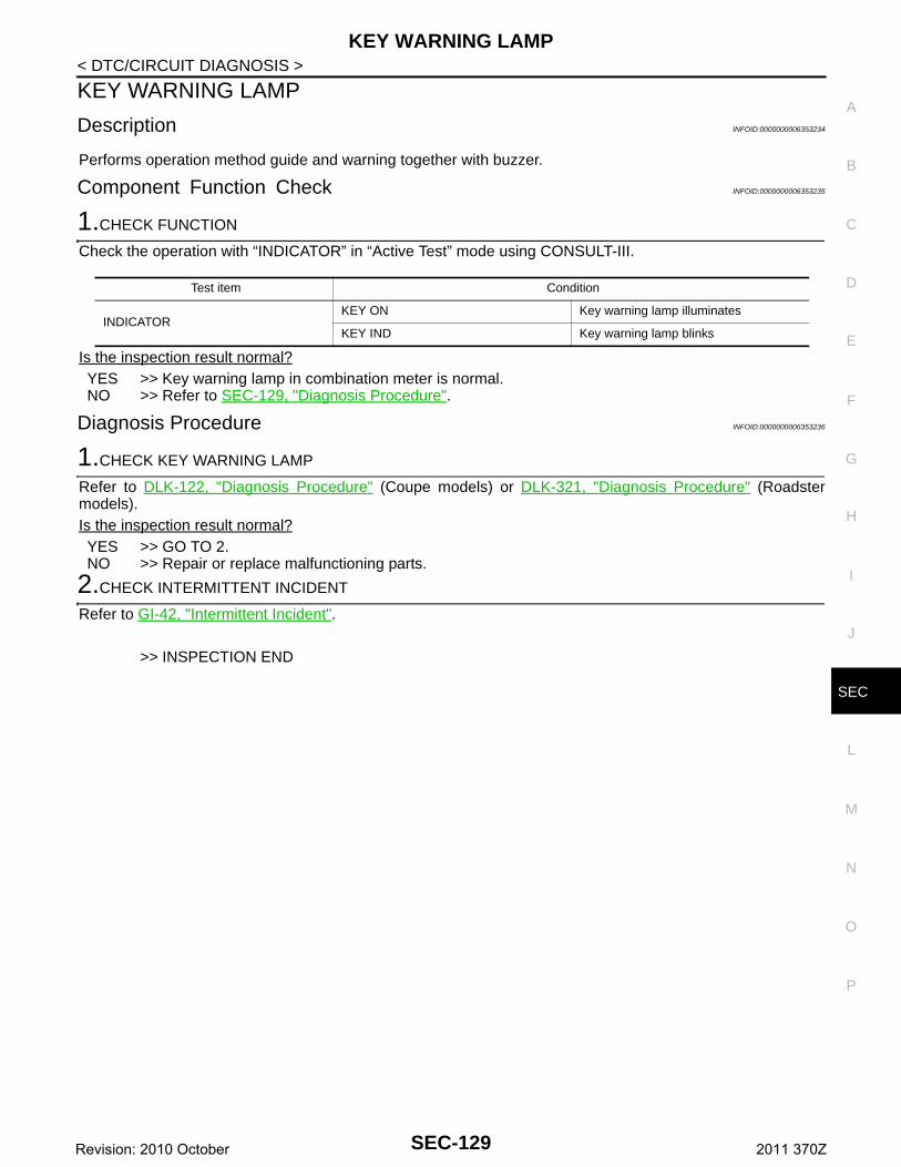
KEY WARNING LAMP
C
D
E
F
G
H
I
J
L
M
A
B
EC
N
O
P
< DTC/CIRCUIT DIAGNOSIS >
S
KEY WARNING LAMP
Description INFOID:0000000006353234
Performs operation method guide and warning together with buzzer.
Component Function Check INFOID:0000000006353235
1.CHECK FUNCTION
Check the operation with “INDICATOR” in “Active Test” mode using CONSULT-III.
Is the inspection result normal?YES >> Key warning lamp in combination meter is normal.NO >> Refer to SEC-129, "Diagnosis Procedure".
Diagnosis Procedure INFOID:0000000006353236
1.CHECK KEY WARNING LAMP
Refer to DLK-122, "Diagnosis Procedure" (Coupe models) or DLK-321, "Diagnosis Procedure" (Roadstermodels).Is the inspection result normal?YES >> GO TO 2.NO >> Repair or replace malfunctioning parts.
2.CHECK INTERMITTENT INCIDENT
Refer to GI-42, "Intermittent Incident".
>> INSPECTION END
Test item Condition
INDICATORKEY ON Key warning lamp illuminates
KEY IND Key warning lamp blinks
SEC-129Revision: 2010 October 2011 370Z
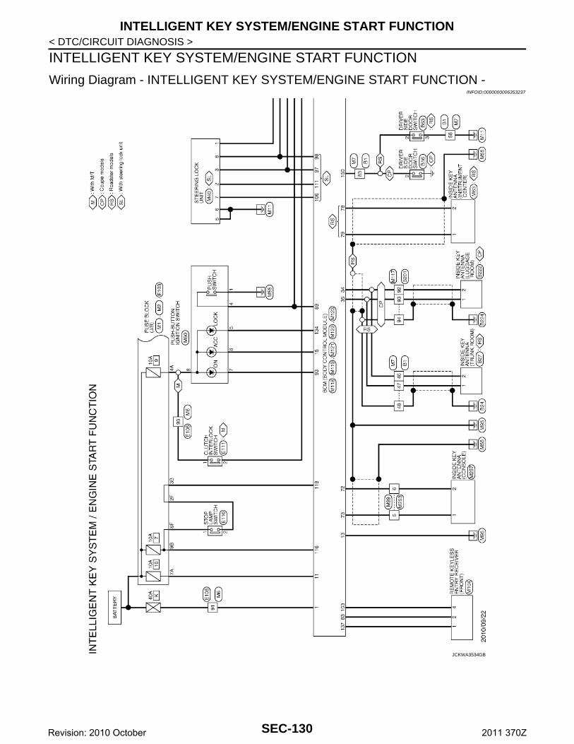
INTELLIGENT KEY SYSTEM/ENGINE START FUNCTION
< DTC/CIRCUIT DIAGNOSIS >INTELLIGENT KEY SYSTEM/ENGINE START FUNCTION
Wiring Diagram - INTELLIGENT KEY SYSTEM/ENGINE START FUNCTION -INFOID:0000000006353237
JCKWA3534GB
SEC-130Revision: 2010 October 2011 370Z
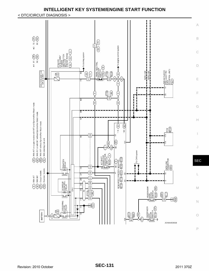
INTELLIGENT KEY SYSTEM/ENGINE START FUNCTION
C
D
E
F
G
H
I
J
L
M
A
B
EC
N
O
P
< DTC/CIRCUIT DIAGNOSIS >
S
JCKWA3535GB
SEC-131Revision: 2010 October 2011 370Z
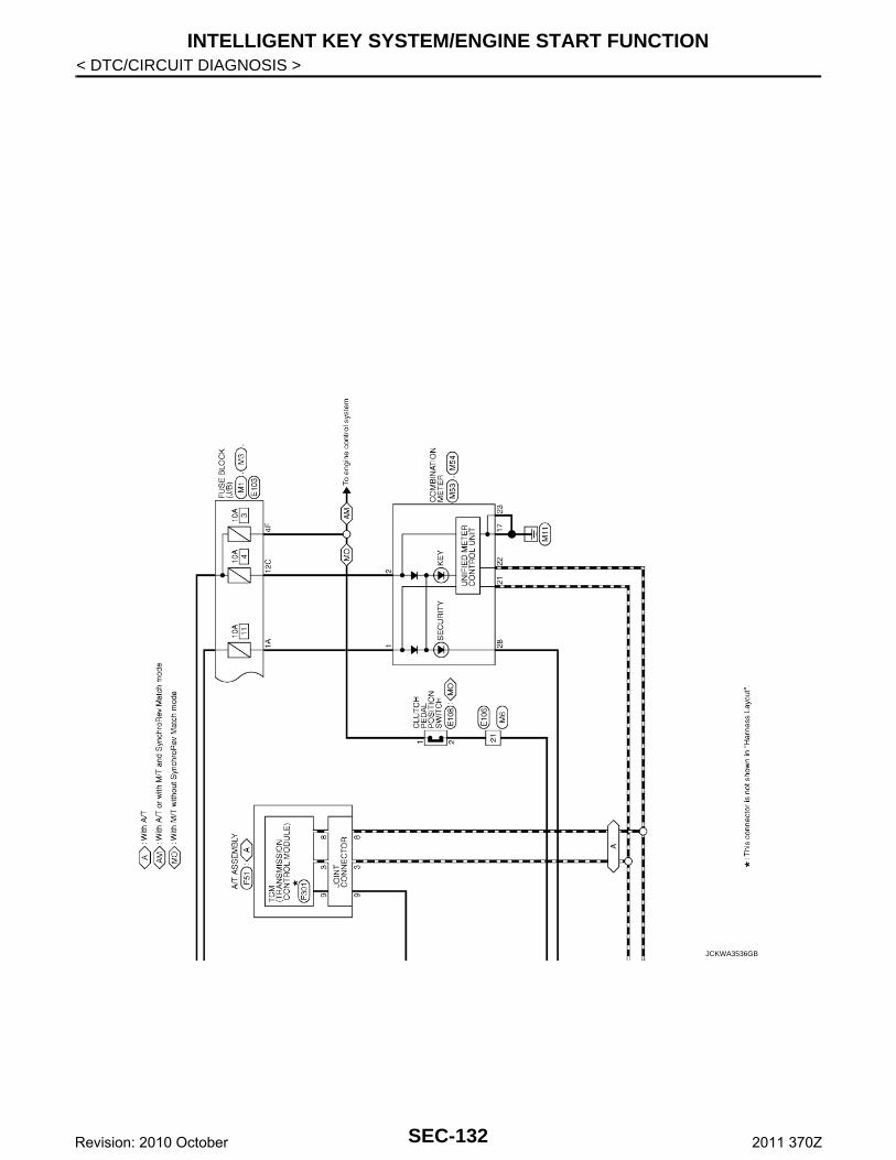
INTELLIGENT KEY SYSTEM/ENGINE START FUNCTION
< DTC/CIRCUIT DIAGNOSIS >JCKWA3536GB
SEC-132Revision: 2010 October 2011 370Z
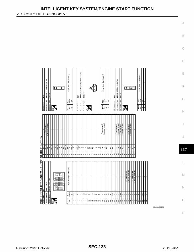
INTELLIGENT KEY SYSTEM/ENGINE START FUNCTION
C
D
E
F
G
H
I
J
L
M
A
B
EC
N
O
P
< DTC/CIRCUIT DIAGNOSIS >
S
JCKWA3537GB
SEC-133Revision: 2010 October 2011 370Z
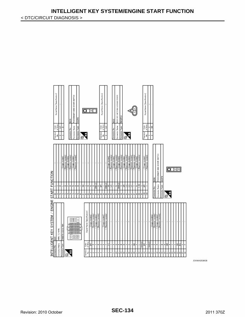
INTELLIGENT KEY SYSTEM/ENGINE START FUNCTION
< DTC/CIRCUIT DIAGNOSIS >JCKWA3538GB
SEC-134Revision: 2010 October 2011 370Z
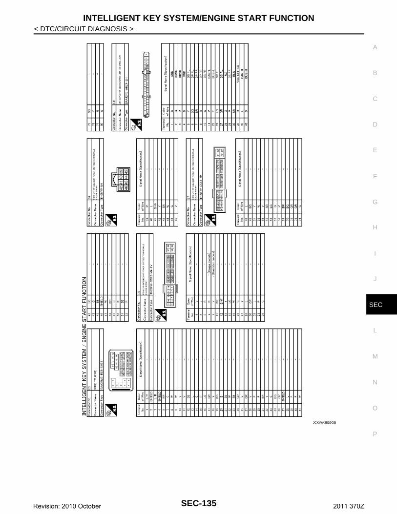
INTELLIGENT KEY SYSTEM/ENGINE START FUNCTION
C
D
E
F
G
H
I
J
L
M
A
B
EC
N
O
P
< DTC/CIRCUIT DIAGNOSIS >
S
JCKWA3539GB
SEC-135Revision: 2010 October 2011 370Z
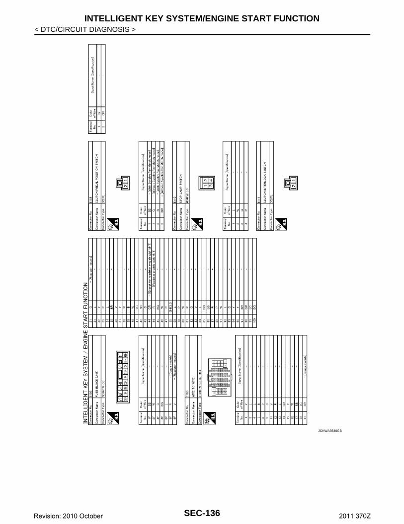
INTELLIGENT KEY SYSTEM/ENGINE START FUNCTION
< DTC/CIRCUIT DIAGNOSIS >JCKWA3540GB
SEC-136Revision: 2010 October 2011 370Z
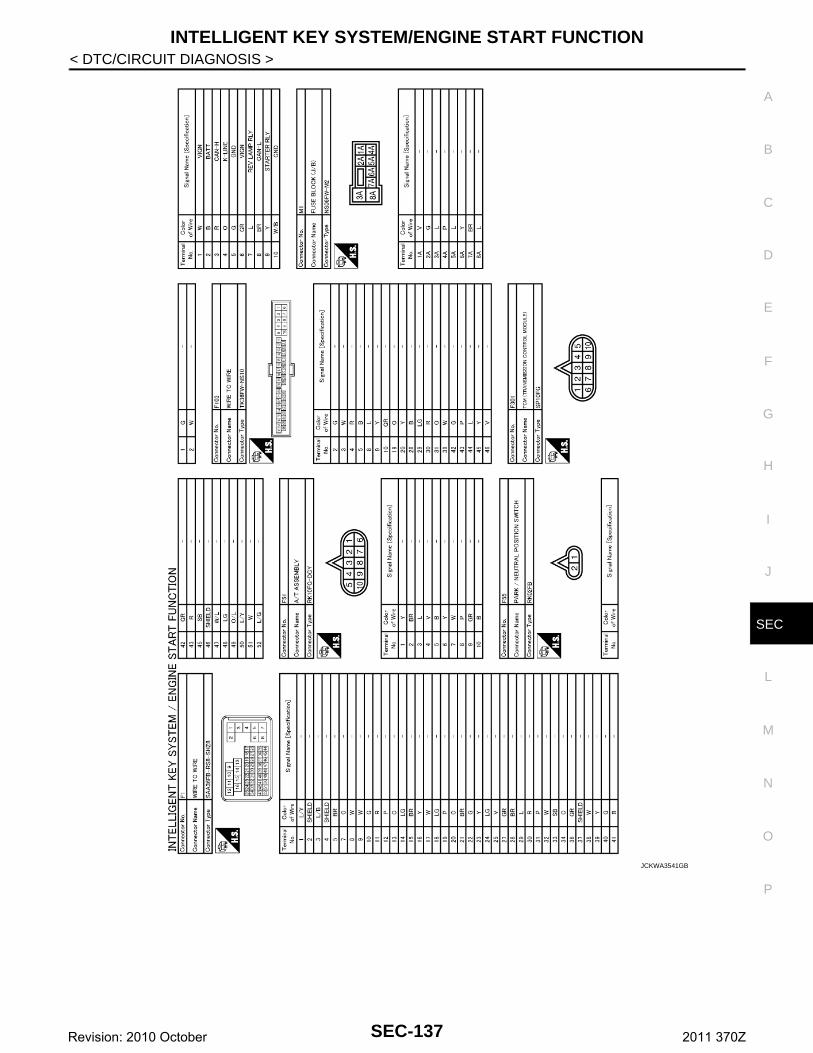
INTELLIGENT KEY SYSTEM/ENGINE START FUNCTION
C
D
E
F
G
H
I
J
L
M
A
B
EC
N
O
P
< DTC/CIRCUIT DIAGNOSIS >
S
JCKWA3541GB
SEC-137Revision: 2010 October 2011 370Z
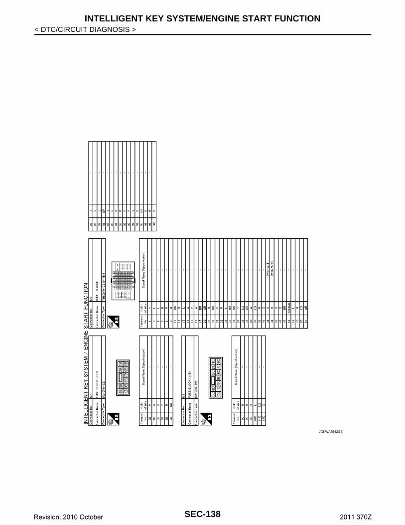
INTELLIGENT KEY SYSTEM/ENGINE START FUNCTION
< DTC/CIRCUIT DIAGNOSIS >JCKWA3542GB
SEC-138Revision: 2010 October 2011 370Z
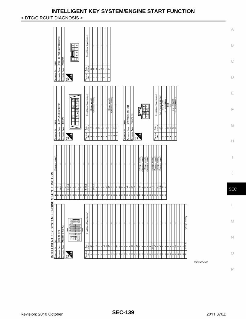
INTELLIGENT KEY SYSTEM/ENGINE START FUNCTION
C
D
E
F
G
H
I
J
L
M
A
B
EC
N
O
P
< DTC/CIRCUIT DIAGNOSIS >
S
JCKWA3543GB
SEC-139Revision: 2010 October 2011 370Z
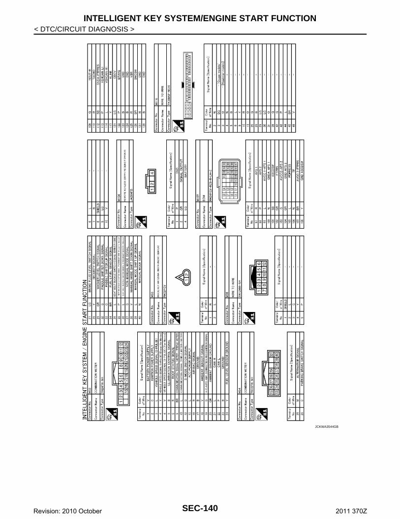
INTELLIGENT KEY SYSTEM/ENGINE START FUNCTION
< DTC/CIRCUIT DIAGNOSIS >JCKWA3544GB
SEC-140Revision: 2010 October 2011 370Z
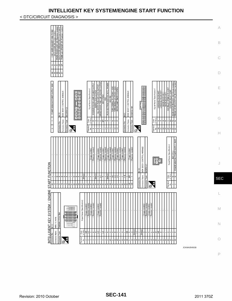
INTELLIGENT KEY SYSTEM/ENGINE START FUNCTION
C
D
E
F
G
H
I
J
L
M
A
B
EC
N
O
P
< DTC/CIRCUIT DIAGNOSIS >
S
JCKWA3545GB
SEC-141Revision: 2010 October 2011 370Z
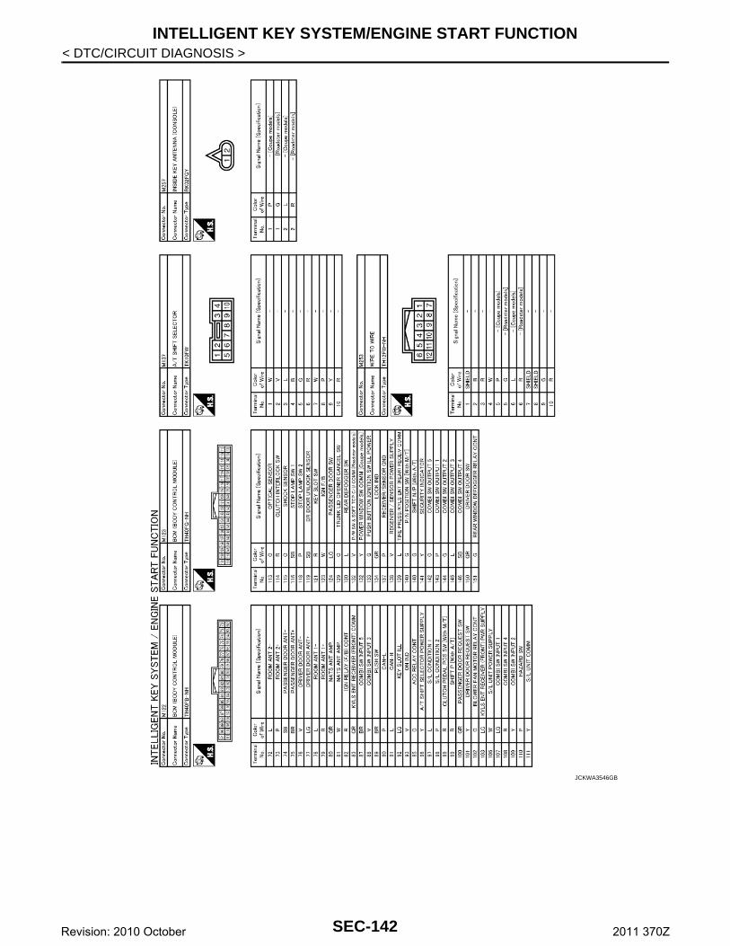
INTELLIGENT KEY SYSTEM/ENGINE START FUNCTION
< DTC/CIRCUIT DIAGNOSIS >JCKWA3546GB
SEC-142Revision: 2010 October 2011 370Z
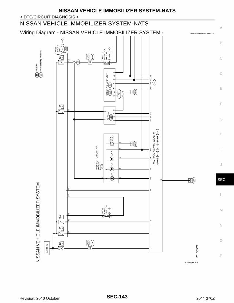
NISSAN VEHICLE IMMOBILIZER SYSTEM-NATS
C
D
E
F
G
H
I
J
L
M
A
B
EC
N
O
P
< DTC/CIRCUIT DIAGNOSIS >
S
NISSAN VEHICLE IMMOBILIZER SYSTEM-NATS
Wiring Diagram - NISSAN VEHICLE IMMOBILIZER SYSTEM - INFOID:0000000006353238
JCKWA3557GB
SEC-143Revision: 2010 October 2011 370Z
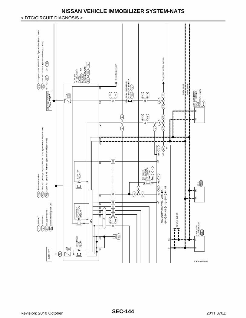
NISSAN VEHICLE IMMOBILIZER SYSTEM-NATS
< DTC/CIRCUIT DIAGNOSIS >JCKWA3558GB
SEC-144Revision: 2010 October 2011 370Z
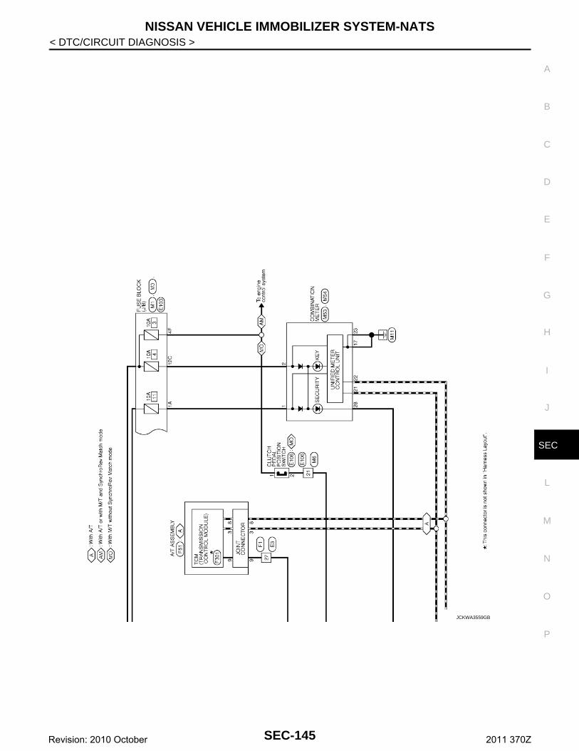
NISSAN VEHICLE IMMOBILIZER SYSTEM-NATS
C
D
E
F
G
H
I
J
L
M
A
B
EC
N
O
P
< DTC/CIRCUIT DIAGNOSIS >
S
JCKWA3559GB
SEC-145Revision: 2010 October 2011 370Z
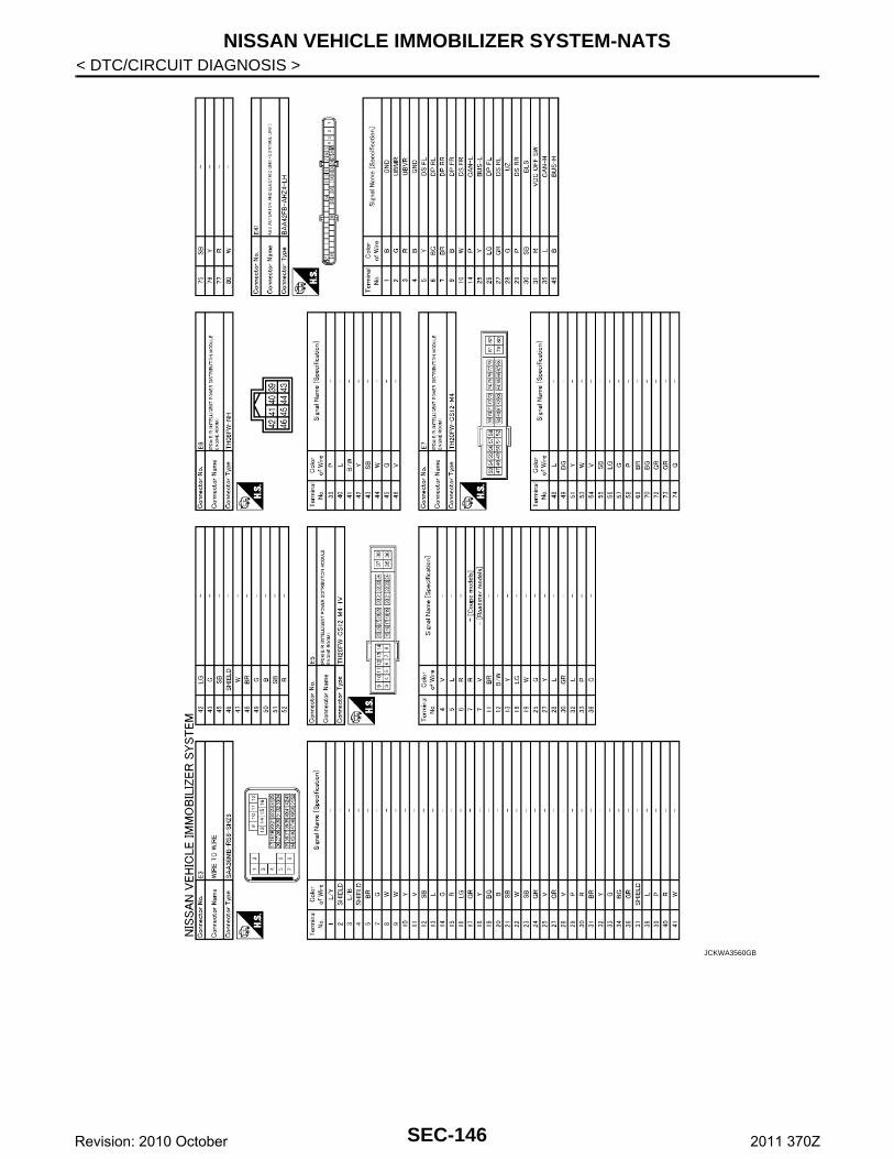
NISSAN VEHICLE IMMOBILIZER SYSTEM-NATS
< DTC/CIRCUIT DIAGNOSIS >JCKWA3560GB
SEC-146Revision: 2010 October 2011 370Z
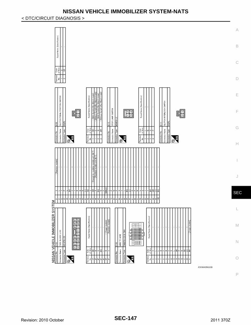
NISSAN VEHICLE IMMOBILIZER SYSTEM-NATS
C
D
E
F
G
H
I
J
L
M
A
B
EC
N
O
P
< DTC/CIRCUIT DIAGNOSIS >
S
JCKWA3561GB
SEC-147Revision: 2010 October 2011 370Z
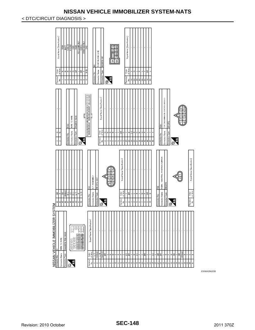
NISSAN VEHICLE IMMOBILIZER SYSTEM-NATS
< DTC/CIRCUIT DIAGNOSIS >JCKWA3562GB
SEC-148Revision: 2010 October 2011 370Z
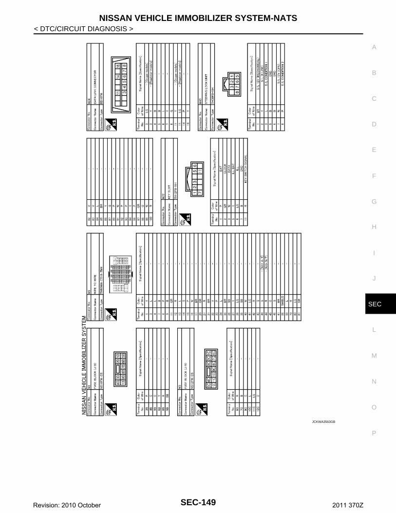
NISSAN VEHICLE IMMOBILIZER SYSTEM-NATS
C
D
E
F
G
H
I
J
L
M
A
B
EC
N
O
P
< DTC/CIRCUIT DIAGNOSIS >
S
JCKWA3563GB
SEC-149Revision: 2010 October 2011 370Z
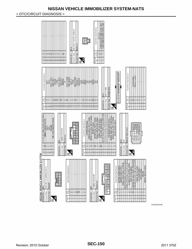
NISSAN VEHICLE IMMOBILIZER SYSTEM-NATS
< DTC/CIRCUIT DIAGNOSIS >JCKWA3564GB
SEC-150Revision: 2010 October 2011 370Z
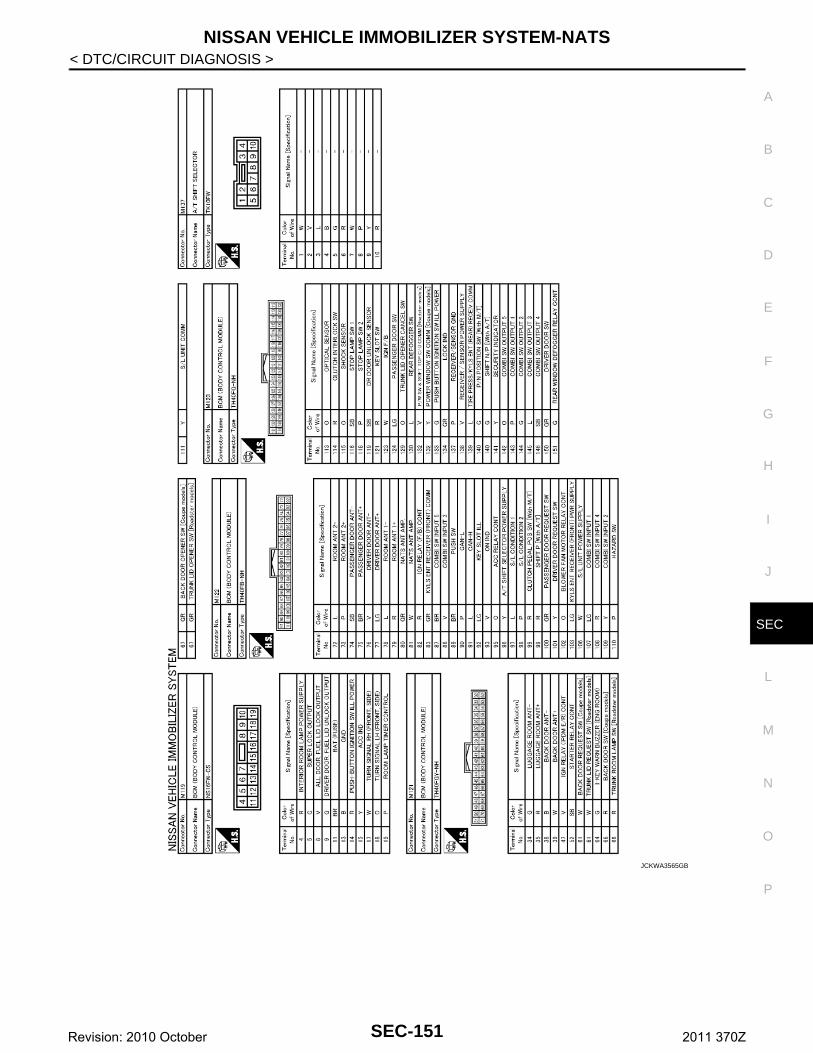
NISSAN VEHICLE IMMOBILIZER SYSTEM-NATS
C
D
E
F
G
H
I
J
L
M
A
B
EC
N
O
P
< DTC/CIRCUIT DIAGNOSIS >
S
JCKWA3565GB
SEC-151Revision: 2010 October 2011 370Z
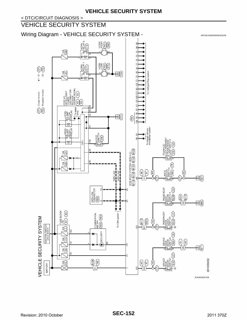
VEHICLE SECURITY SYSTEM
< DTC/CIRCUIT DIAGNOSIS >VEHICLE SECURITY SYSTEM
Wiring Diagram - VEHICLE SECURITY SYSTEM - INFOID:0000000006353239
JCKWA3547GB
SEC-152Revision: 2010 October 2011 370Z
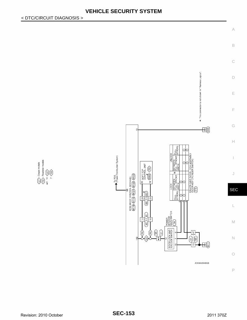
VEHICLE SECURITY SYSTEM
C
D
E
F
G
H
I
J
L
M
A
B
EC
N
O
P
< DTC/CIRCUIT DIAGNOSIS >
S
JCKWA3548GB
SEC-153Revision: 2010 October 2011 370Z
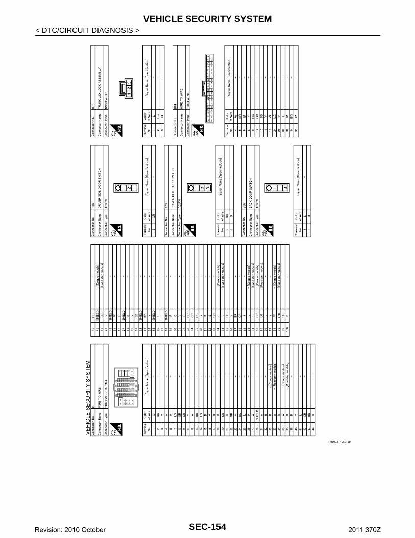
VEHICLE SECURITY SYSTEM
< DTC/CIRCUIT DIAGNOSIS >JCKWA3549GB
SEC-154Revision: 2010 October 2011 370Z
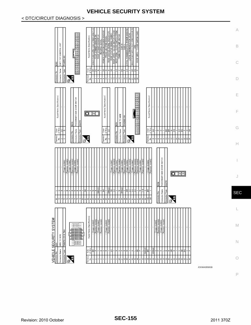
VEHICLE SECURITY SYSTEM
C
D
E
F
G
H
I
J
L
M
A
B
EC
N
O
P
< DTC/CIRCUIT DIAGNOSIS >
S
JCKWA3550GB
SEC-155Revision: 2010 October 2011 370Z
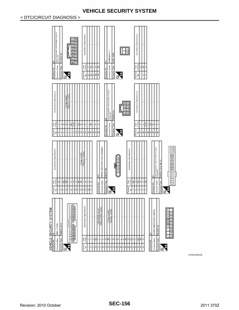
VEHICLE SECURITY SYSTEM
< DTC/CIRCUIT DIAGNOSIS >JCKWA3551GB
SEC-156Revision: 2010 October 2011 370Z
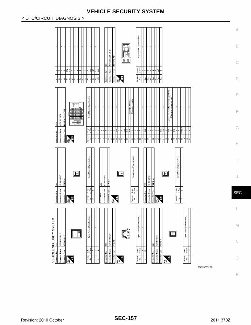
VEHICLE SECURITY SYSTEM
C
D
E
F
G
H
I
J
L
M
A
B
EC
N
O
P
< DTC/CIRCUIT DIAGNOSIS >
S
JCKWA3552GB
SEC-157Revision: 2010 October 2011 370Z
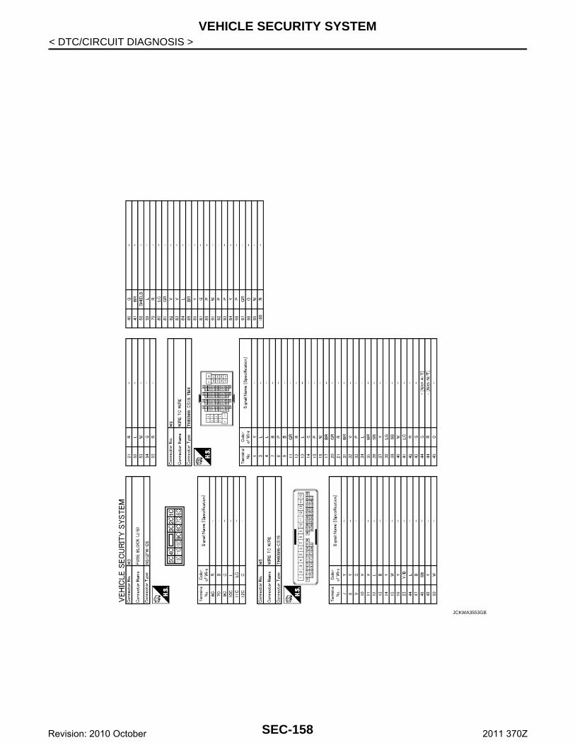
VEHICLE SECURITY SYSTEM
< DTC/CIRCUIT DIAGNOSIS >JCKWA3553GB
SEC-158Revision: 2010 October 2011 370Z
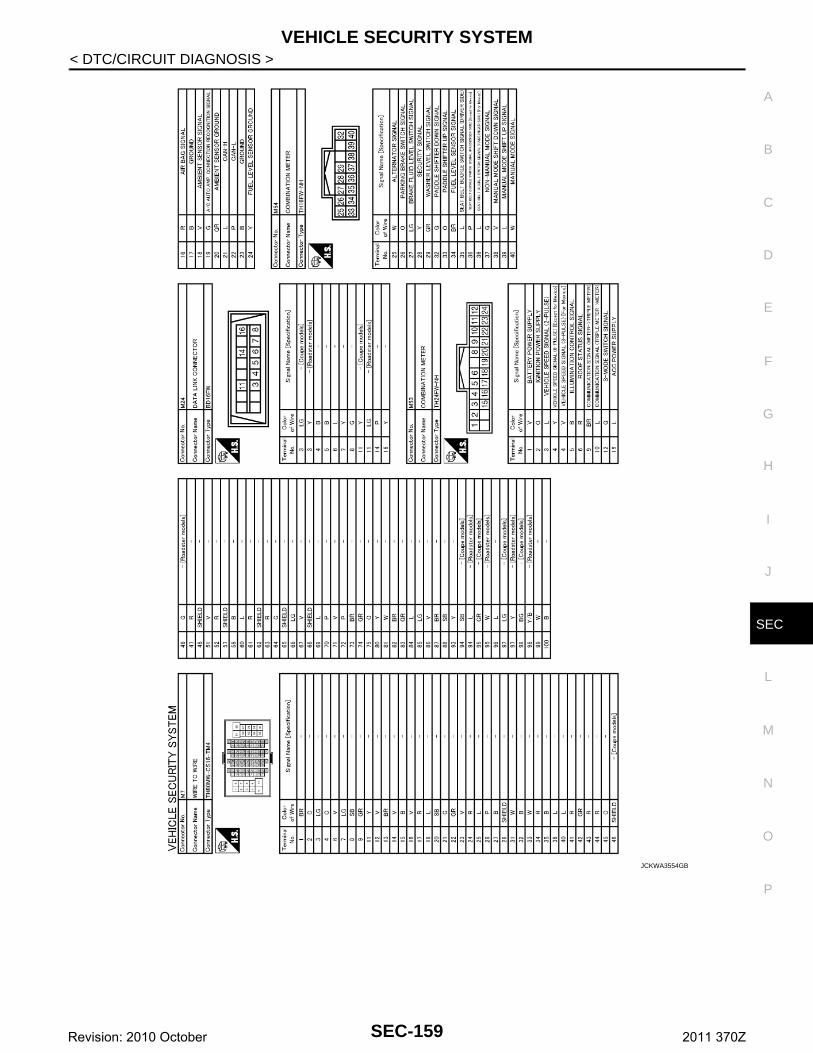
VEHICLE SECURITY SYSTEM
C
D
E
F
G
H
I
J
L
M
A
B
EC
N
O
P
< DTC/CIRCUIT DIAGNOSIS >
S
JCKWA3554GB
SEC-159Revision: 2010 October 2011 370Z
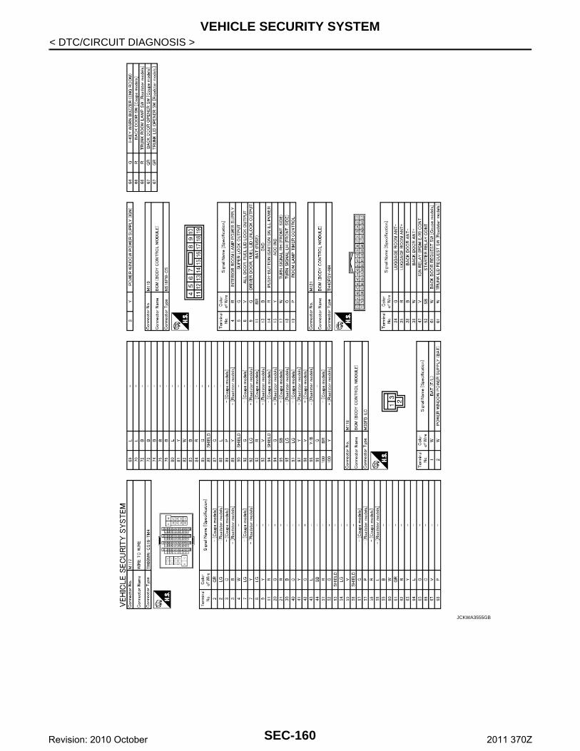
VEHICLE SECURITY SYSTEM
< DTC/CIRCUIT DIAGNOSIS >JCKWA3555GB
SEC-160Revision: 2010 October 2011 370Z
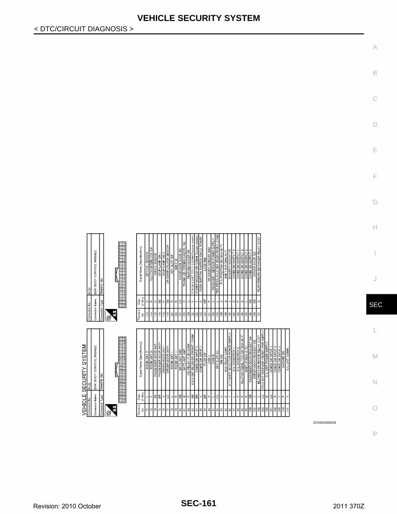
VEHICLE SECURITY SYSTEM
C
D
E
F
G
H
I
J
L
M
A
B
EC
N
O
P
< DTC/CIRCUIT DIAGNOSIS >
S
JCKWA3556GB
SEC-161Revision: 2010 October 2011 370Z
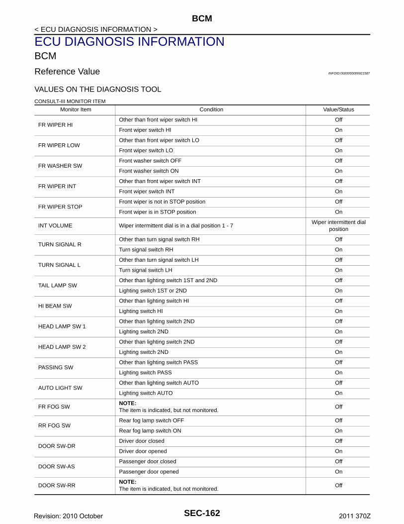
BCM
< ECU DIAGNOSIS INFORMATION >ECU DIAGNOSIS INFORMATIONBCM
Reference Value INFOID:0000000006921587
VALUES ON THE DIAGNOSIS TOOL
CONSULT-III MONITOR ITEM
Monitor Item Condition Value/Status
FR WIPER HIOther than front wiper switch HI Off
Front wiper switch HI On
FR WIPER LOWOther than front wiper switch LO Off
Front wiper switch LO On
FR WASHER SWFront washer switch OFF Off
Front washer switch ON On
FR WIPER INTOther than front wiper switch INT Off
Front wiper switch INT On
FR WIPER STOPFront wiper is not in STOP position Off
Front wiper is in STOP position On
INT VOLUME Wiper intermittent dial is in a dial position 1 - 7Wiper intermittent dial
position
TURN SIGNAL ROther than turn signal switch RH Off
Turn signal switch RH On
TURN SIGNAL LOther than turn signal switch LH Off
Turn signal switch LH On
TAIL LAMP SWOther than lighting switch 1ST and 2ND Off
Lighting switch 1ST or 2ND On
HI BEAM SWOther than lighting switch HI Off
Lighting switch HI On
HEAD LAMP SW 1Other than lighting switch 2ND Off
Lighting switch 2ND On
HEAD LAMP SW 2Other than lighting switch 2ND Off
Lighting switch 2ND On
PASSING SWOther than lighting switch PASS Off
Lighting switch PASS On
AUTO LIGHT SWOther than lighting switch AUTO Off
Lighting switch AUTO On
FR FOG SWNOTE:The item is indicated, but not monitored.
Off
RR FOG SWRear fog lamp switch OFF Off
Rear fog lamp switch ON On
DOOR SW-DRDriver door closed Off
Driver door opened On
DOOR SW-ASPassenger door closed Off
Passenger door opened On
DOOR SW-RRNOTE:The item is indicated, but not monitored.
Off
SEC-162Revision: 2010 October 2011 370Z
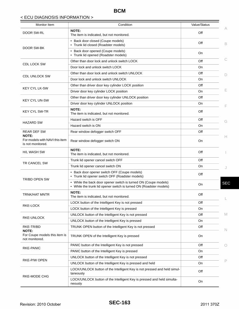
BCM
C
D
E
F
G
H
I
J
L
M
A
B
EC
N
O
P
< ECU DIAGNOSIS INFORMATION >
S
DOOR SW-RLNOTE:The item is indicated, but not monitored.
Off
DOOR SW-BK
• Back door closed (Coupe models)• Trunk lid closed (Roadster models)
Off
• Back door opened (Coupe models)• Trunk lid opened (Roadster models)
On
CDL LOCK SWOther than door lock and unlock switch LOCK Off
Door lock and unlock switch LOCK On
CDL UNLOCK SWOther than door lock and unlock switch UNLOCK Off
Door lock and unlock switch UNLOCK On
KEY CYL LK-SWOther than driver door key cylinder LOCK position Off
Driver door key cylinder LOCK position On
KEY CYL UN-SWOther than driver door key cylinder UNLOCK position Off
Driver door key cylinder UNLOCK position On
KEY CYL SW-TRNOTE:The item is indicated, but not monitored.
Off
HAZARD SWHazard switch is OFF Off
Hazard switch is ON On
REAR DEF SWNOTE:For models with NAVI this item is not monitored.
Rear window defogger switch OFF Off
Rear window defogger switch ON On
H/L WASH SWNOTE:The item is indicated, but not monitored.
Off
TR CANCEL SWTrunk lid opener cancel switch OFF Off
Trunk lid opener cancel switch ON On
TR/BD OPEN SW
• Back door opener switch OFF (Coupe models)• Trunk lid opener switch OFF (Roadster models)
Off
• While the back door opener switch is turned ON (Coupe models)• While the trunk lid opener switch is turned ON (Roadster models)
On
TRNK/HAT MNTRNOTE:The item is indicated, but not monitored.
Off
RKE-LOCKLOCK button of the Intelligent Key is not pressed Off
LOCK button of the Intelligent Key is pressed On
RKE-UNLOCKUNLOCK button of the Intelligent Key is not pressed Off
UNLOCK button of the Intelligent Key is pressed On
RKE-TR/BDNOTE:For Coupe models this item is not monitored.
TRUNK OPEN button of the Intelligent Key is not pressed Off
TRUNK OPEN of the Intelligent Key is pressed On
RKE-PANICPANIC button of the Intelligent Key is not pressed Off
PANIC button of the Intelligent Key is pressed On
RKE-P/W OPENUNLOCK button of the Intelligent Key is not pressed Off
UNLOCK button of the Intelligent Key is pressed and held On
RKE-MODE CHG
LOCK/UNLOCK button of the Intelligent Key is not pressed and held simul-taneously
Off
LOCK/UNLOCK button of the Intelligent Key is pressed and held simulta-neously
On
Monitor Item Condition Value/Status
SEC-163Revision: 2010 October 2011 370Z
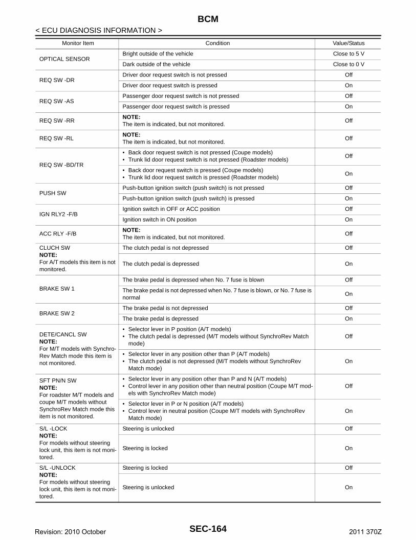
BCM
< ECU DIAGNOSIS INFORMATION >OPTICAL SENSORBright outside of the vehicle Close to 5 V
Dark outside of the vehicle Close to 0 V
REQ SW -DRDriver door request switch is not pressed Off
Driver door request switch is pressed On
REQ SW -ASPassenger door request switch is not pressed Off
Passenger door request switch is pressed On
REQ SW -RRNOTE:The item is indicated, but not monitored.
Off
REQ SW -RLNOTE:The item is indicated, but not monitored.
Off
REQ SW -BD/TR
• Back door request switch is not pressed (Coupe models)• Trunk lid door request switch is not pressed (Roadster models)
Off
• Back door request switch is pressed (Coupe models)• Trunk lid door request switch is pressed (Roadster models)
On
PUSH SWPush-button ignition switch (push switch) is not pressed Off
Push-button ignition switch (push switch) is pressed On
IGN RLY2 -F/BIgnition switch in OFF or ACC position Off
Ignition switch in ON position On
ACC RLY -F/BNOTE:The item is indicated, but not monitored.
Off
CLUCH SWNOTE:For A/T models this item is not monitored.
The clutch pedal is not depressed Off
The clutch pedal is depressed On
BRAKE SW 1
The brake pedal is depressed when No. 7 fuse is blown Off
The brake pedal is not depressed when No. 7 fuse is blown, or No. 7 fuse is normal
On
BRAKE SW 2The brake pedal is not depressed Off
The brake pedal is depressed On
DETE/CANCL SWNOTE:For M/T models with Synchro-Rev Match mode this item is not monitored.
• Selector lever in P position (A/T models)• The clutch pedal is depressed (M/T models without SynchroRev Match
mode)Off
• Selector lever in any position other than P (A/T models)• The clutch pedal is not depressed (M/T models without SynchroRev
Match mode)On
SFT PN/N SWNOTE:For roadster M/T models and coupe M/T models without SynchroRev Match mode this item is not monitored.
• Selector lever in any position other than P and N (A/T models)• Control lever in any position other than neutral position (Coupe M/T mod-
els with SynchroRev Match mode)Off
• Selector lever in P or N position (A/T models)• Control lever in neutral position (Coupe M/T models with SynchroRev
Match mode)On
S/L -LOCKNOTE:For models without steering lock unit, this item is not moni-tored.
Steering is unlocked Off
Steering is locked On
S/L -UNLOCKNOTE:For models without steering lock unit, this item is not moni-tored.
Steering is locked Off
Steering is unlocked On
Monitor Item Condition Value/Status
SEC-164Revision: 2010 October 2011 370Z
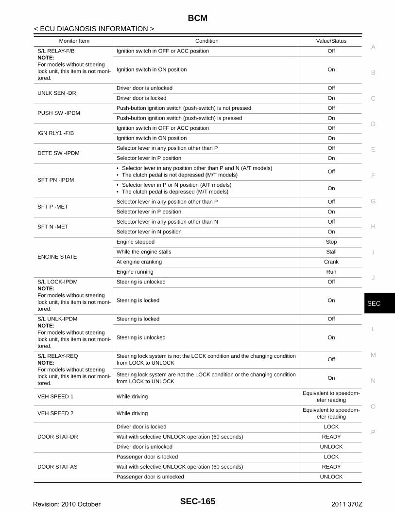
BCM
C
D
E
F
G
H
I
J
L
M
A
B
EC
N
O
P
< ECU DIAGNOSIS INFORMATION >
S
S/L RELAY-F/BNOTE:For models without steering lock unit, this item is not moni-tored.
Ignition switch in OFF or ACC position Off
Ignition switch in ON position On
UNLK SEN -DRDriver door is unlocked Off
Driver door is locked On
PUSH SW -IPDMPush-button ignition switch (push-switch) is not pressed Off
Push-button ignition switch (push-switch) is pressed On
IGN RLY1 -F/BIgnition switch in OFF or ACC position Off
Ignition switch in ON position On
DETE SW -IPDMSelector lever in any position other than P Off
Selector lever in P position On
SFT PN -IPDM
• Selector lever in any position other than P and N (A/T models)• The clutch pedal is not depressed (M/T models)
Off
• Selector lever in P or N position (A/T models)• The clutch pedal is depressed (M/T models)
On
SFT P -METSelector lever in any position other than P Off
Selector lever in P position On
SFT N -METSelector lever in any position other than N Off
Selector lever in N position On
ENGINE STATE
Engine stopped Stop
While the engine stalls Stall
At engine cranking Crank
Engine running Run
S/L LOCK-IPDMNOTE:For models without steering lock unit, this item is not moni-tored.
Steering is unlocked Off
Steering is locked On
S/L UNLK-IPDMNOTE:For models without steering lock unit, this item is not moni-tored.
Steering is locked Off
Steering is unlocked On
S/L RELAY-REQNOTE:For models without steering lock unit, this item is not moni-tored.
Steering lock system is not the LOCK condition and the changing condition from LOCK to UNLOCK
Off
Steering lock system are not the LOCK condition or the changing condition from LOCK to UNLOCK
On
VEH SPEED 1 While drivingEquivalent to speedom-
eter reading
VEH SPEED 2 While drivingEquivalent to speedom-
eter reading
DOOR STAT-DR
Driver door is locked LOCK
Wait with selective UNLOCK operation (60 seconds) READY
Driver door is unlocked UNLOCK
DOOR STAT-AS
Passenger door is locked LOCK
Wait with selective UNLOCK operation (60 seconds) READY
Passenger door is unlocked UNLOCK
Monitor Item Condition Value/Status
SEC-165Revision: 2010 October 2011 370Z
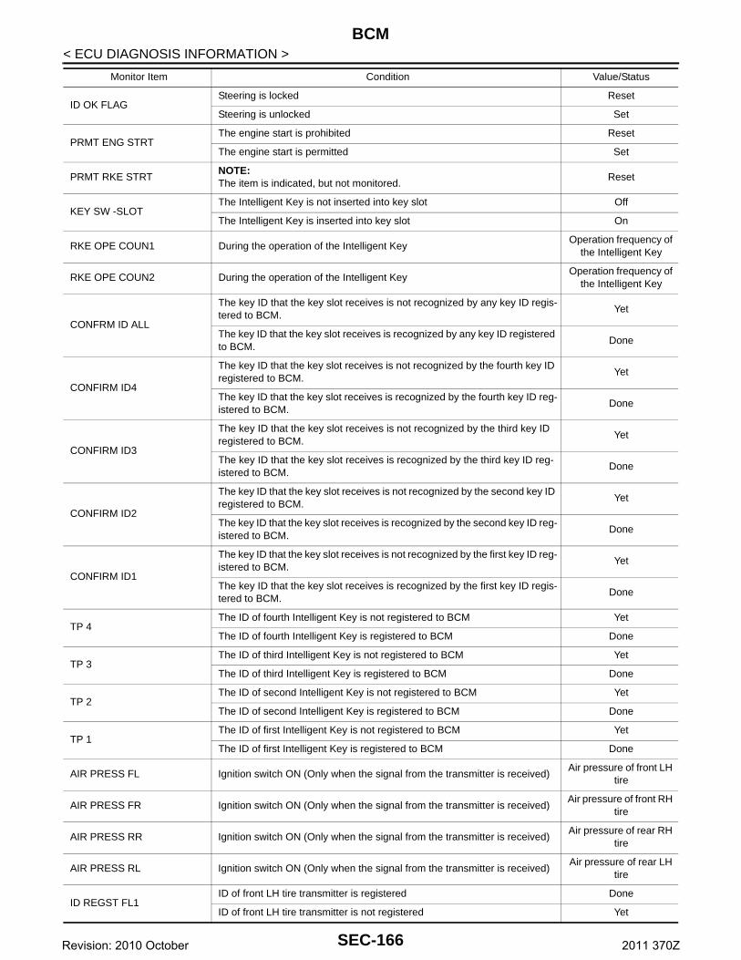
BCM
< ECU DIAGNOSIS INFORMATION >ID OK FLAGSteering is locked Reset
Steering is unlocked Set
PRMT ENG STRTThe engine start is prohibited Reset
The engine start is permitted Set
PRMT RKE STRTNOTE:The item is indicated, but not monitored.
Reset
KEY SW -SLOTThe Intelligent Key is not inserted into key slot Off
The Intelligent Key is inserted into key slot On
RKE OPE COUN1 During the operation of the Intelligent KeyOperation frequency of
the Intelligent Key
RKE OPE COUN2 During the operation of the Intelligent KeyOperation frequency of
the Intelligent Key
CONFRM ID ALL
The key ID that the key slot receives is not recognized by any key ID regis-tered to BCM.
Yet
The key ID that the key slot receives is recognized by any key ID registered to BCM.
Done
CONFIRM ID4
The key ID that the key slot receives is not recognized by the fourth key ID registered to BCM.
Yet
The key ID that the key slot receives is recognized by the fourth key ID reg-istered to BCM.
Done
CONFIRM ID3
The key ID that the key slot receives is not recognized by the third key ID registered to BCM.
Yet
The key ID that the key slot receives is recognized by the third key ID reg-istered to BCM.
Done
CONFIRM ID2
The key ID that the key slot receives is not recognized by the second key ID registered to BCM.
Yet
The key ID that the key slot receives is recognized by the second key ID reg-istered to BCM.
Done
CONFIRM ID1
The key ID that the key slot receives is not recognized by the first key ID reg-istered to BCM.
Yet
The key ID that the key slot receives is recognized by the first key ID regis-tered to BCM.
Done
TP 4The ID of fourth Intelligent Key is not registered to BCM Yet
The ID of fourth Intelligent Key is registered to BCM Done
TP 3The ID of third Intelligent Key is not registered to BCM Yet
The ID of third Intelligent Key is registered to BCM Done
TP 2The ID of second Intelligent Key is not registered to BCM Yet
The ID of second Intelligent Key is registered to BCM Done
TP 1The ID of first Intelligent Key is not registered to BCM Yet
The ID of first Intelligent Key is registered to BCM Done
AIR PRESS FL Ignition switch ON (Only when the signal from the transmitter is received)Air pressure of front LH
tire
AIR PRESS FR Ignition switch ON (Only when the signal from the transmitter is received)Air pressure of front RH
tire
AIR PRESS RR Ignition switch ON (Only when the signal from the transmitter is received)Air pressure of rear RH
tire
AIR PRESS RL Ignition switch ON (Only when the signal from the transmitter is received)Air pressure of rear LH
tire
ID REGST FL1ID of front LH tire transmitter is registered Done
ID of front LH tire transmitter is not registered Yet
Monitor Item Condition Value/Status
SEC-166Revision: 2010 October 2011 370Z
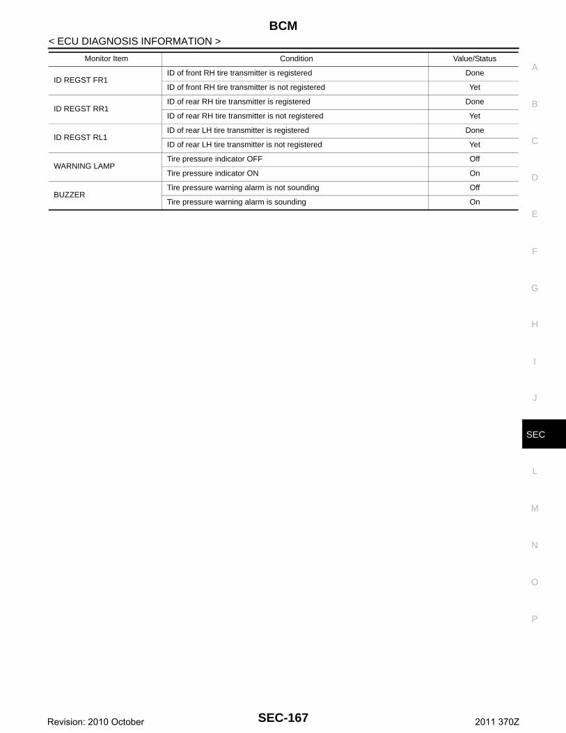
BCM
C
D
E
F
G
H
I
J
L
M
A
B
EC
N
O
P
< ECU DIAGNOSIS INFORMATION >
S
ID REGST FR1ID of front RH tire transmitter is registered Done
ID of front RH tire transmitter is not registered Yet
ID REGST RR1ID of rear RH tire transmitter is registered Done
ID of rear RH tire transmitter is not registered Yet
ID REGST RL1ID of rear LH tire transmitter is registered Done
ID of rear LH tire transmitter is not registered Yet
WARNING LAMPTire pressure indicator OFF Off
Tire pressure indicator ON On
BUZZERTire pressure warning alarm is not sounding Off
Tire pressure warning alarm is sounding On
Monitor Item Condition Value/Status
SEC-167Revision: 2010 October 2011 370Z
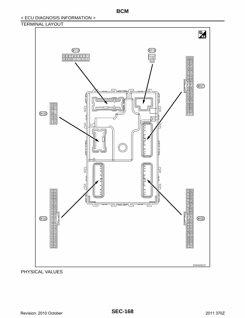
BCM
< ECU DIAGNOSIS INFORMATION >TERMINAL LAYOUT
PHYSICAL VALUES
JPMIA0062ZZ
SEC-168Revision: 2010 October 2011 370Z
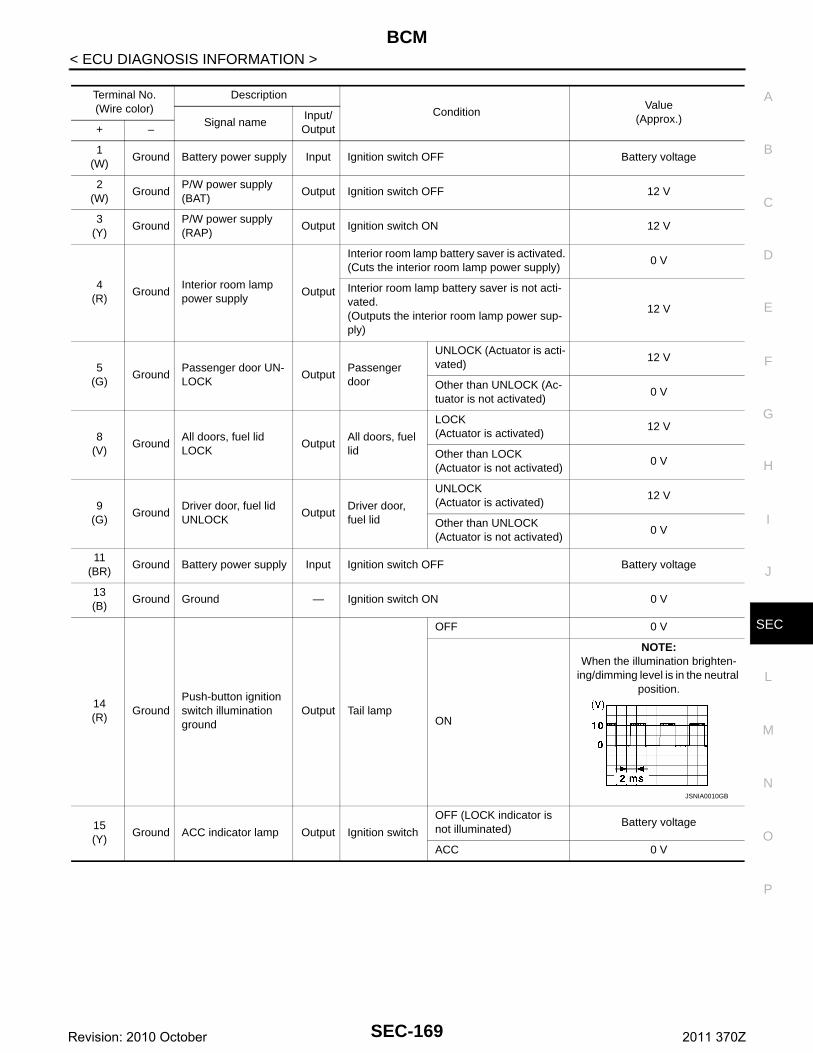
BCM
C
D
E
F
G
H
I
J
L
M
A
B
EC
N
O
P
< ECU DIAGNOSIS INFORMATION >
S
Terminal No.(Wire color)
Description
ConditionValue
(Approx.)Signal nameInput/ Output+ –
1(W)
Ground Battery power supply Input Ignition switch OFF Battery voltage
2(W)
GroundP/W power supply (BAT)
Output Ignition switch OFF 12 V
3(Y)
GroundP/W power supply (RAP)
Output Ignition switch ON 12 V
4(R)
GroundInterior room lamp power supply
Output
Interior room lamp battery saver is activated.(Cuts the interior room lamp power supply)
0 V
Interior room lamp battery saver is not acti-vated.(Outputs the interior room lamp power sup-ply)
12 V
5(G)
GroundPassenger door UN-LOCK
OutputPassenger door
UNLOCK (Actuator is acti-vated)
12 V
Other than UNLOCK (Ac-tuator is not activated)
0 V
8(V)
GroundAll doors, fuel lid LOCK
OutputAll doors, fuel lid
LOCK(Actuator is activated)
12 V
Other than LOCK(Actuator is not activated)
0 V
9(G)
GroundDriver door, fuel lid UNLOCK
OutputDriver door, fuel lid
UNLOCK(Actuator is activated)
12 V
Other than UNLOCK(Actuator is not activated)
0 V
11(BR)
Ground Battery power supply Input Ignition switch OFF Battery voltage
13(B)
Ground Ground — Ignition switch ON 0 V
14(R)
GroundPush-button ignition switch illumination ground
Output Tail lamp
OFF 0 V
ON
NOTE:When the illumination brighten-
ing/dimming level is in the neutral position.
15(Y)
Ground ACC indicator lamp Output Ignition switch
OFF (LOCK indicator is not illuminated)
Battery voltage
ACC 0 V
JSNIA0010GB
SEC-169Revision: 2010 October 2011 370Z
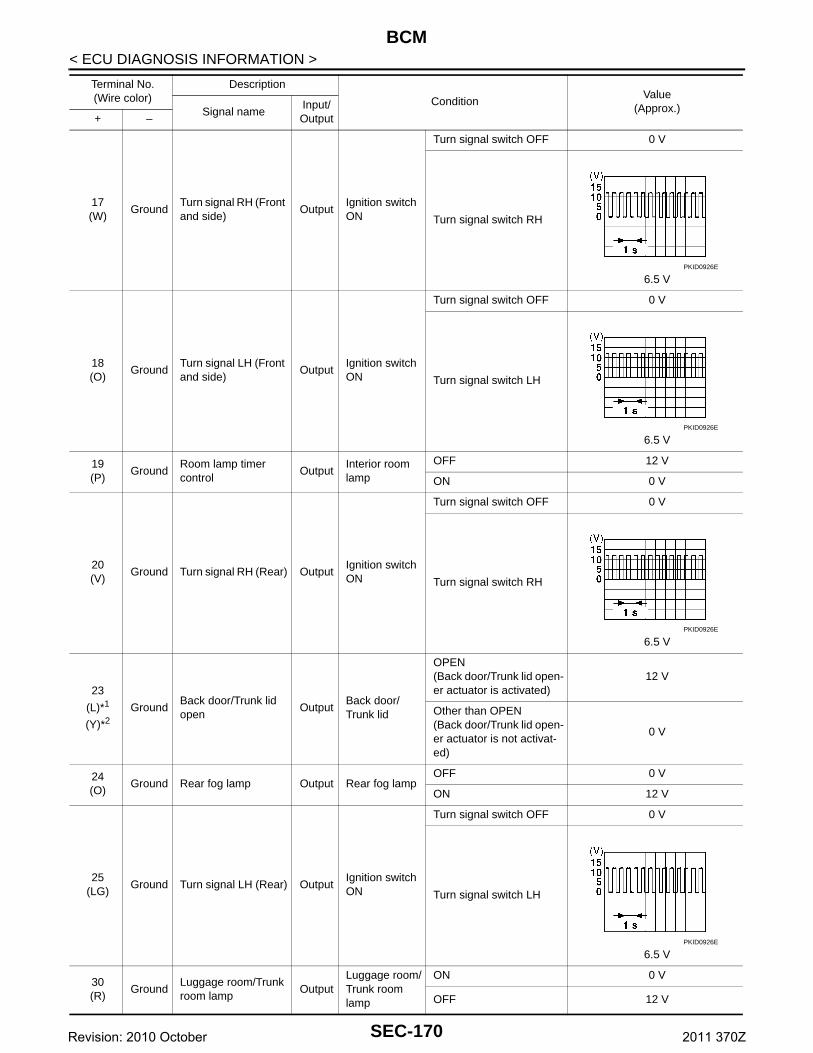
BCM
< ECU DIAGNOSIS INFORMATION >17(W)
GroundTurn signal RH (Front and side)
OutputIgnition switch ON
Turn signal switch OFF 0 V
Turn signal switch RH
6.5 V
18(O)
GroundTurn signal LH (Front and side)
OutputIgnition switch ON
Turn signal switch OFF 0 V
Turn signal switch LH
6.5 V
19(P)
GroundRoom lamp timer control
OutputInterior room lamp
OFF 12 V
ON 0 V
20(V)
Ground Turn signal RH (Rear) OutputIgnition switch ON
Turn signal switch OFF 0 V
Turn signal switch RH
6.5 V
23
(L)*1
(Y)*2Ground
Back door/Trunk lid open
OutputBack door/Trunk lid
OPEN(Back door/Trunk lid open-er actuator is activated)
12 V
Other than OPEN(Back door/Trunk lid open-er actuator is not activat-ed)
0 V
24(O)
Ground Rear fog lamp Output Rear fog lampOFF 0 V
ON 12 V
25(LG)
Ground Turn signal LH (Rear) OutputIgnition switch ON
Turn signal switch OFF 0 V
Turn signal switch LH
6.5 V
30(R)
GroundLuggage room/Trunk room lamp
OutputLuggage room/Trunk room lamp
ON 0 V
OFF 12 V
Terminal No.(Wire color)
Description
ConditionValue
(Approx.)Signal nameInput/ Output+ –
PKID0926E
PKID0926E
PKID0926E
PKID0926E
SEC-170Revision: 2010 October 2011 370Z

BCM
C
D
E
F
G
H
I
J
L
M
A
B
EC
N
O
P
< ECU DIAGNOSIS INFORMATION >
S
34(G)
GroundLuggage room/Trunk room antenna (−)
OutputIgnition switch OFF
When Intelligent Key is in the passenger compart-ment
When Intelligent Key is not in the passenger compart-ment
35(R)
GroundLuggage room/Trunk room antenna (+)
OutputIgnition switch OFF
When Intelligent Key is in the passenger compart-ment
When Intelligent Key is not in the passenger compart-ment
38(B)
GroundRear bumper anten-na (−)
Output
When the back door/trunk lid door request switch is oper-ated with igni-tion switch OFF
When Intelligent Key is in the antenna detection area
When Intelligent Key is not in the antenna detection area
Terminal No.(Wire color)
Description
ConditionValue
(Approx.)Signal nameInput/ Output+ –
JMKIA0062GB
JMKIA0063GB
JMKIA0062GB
JMKIA0063GB
JMKIA0062GB
JMKIA0063GB
SEC-171Revision: 2010 October 2011 370Z
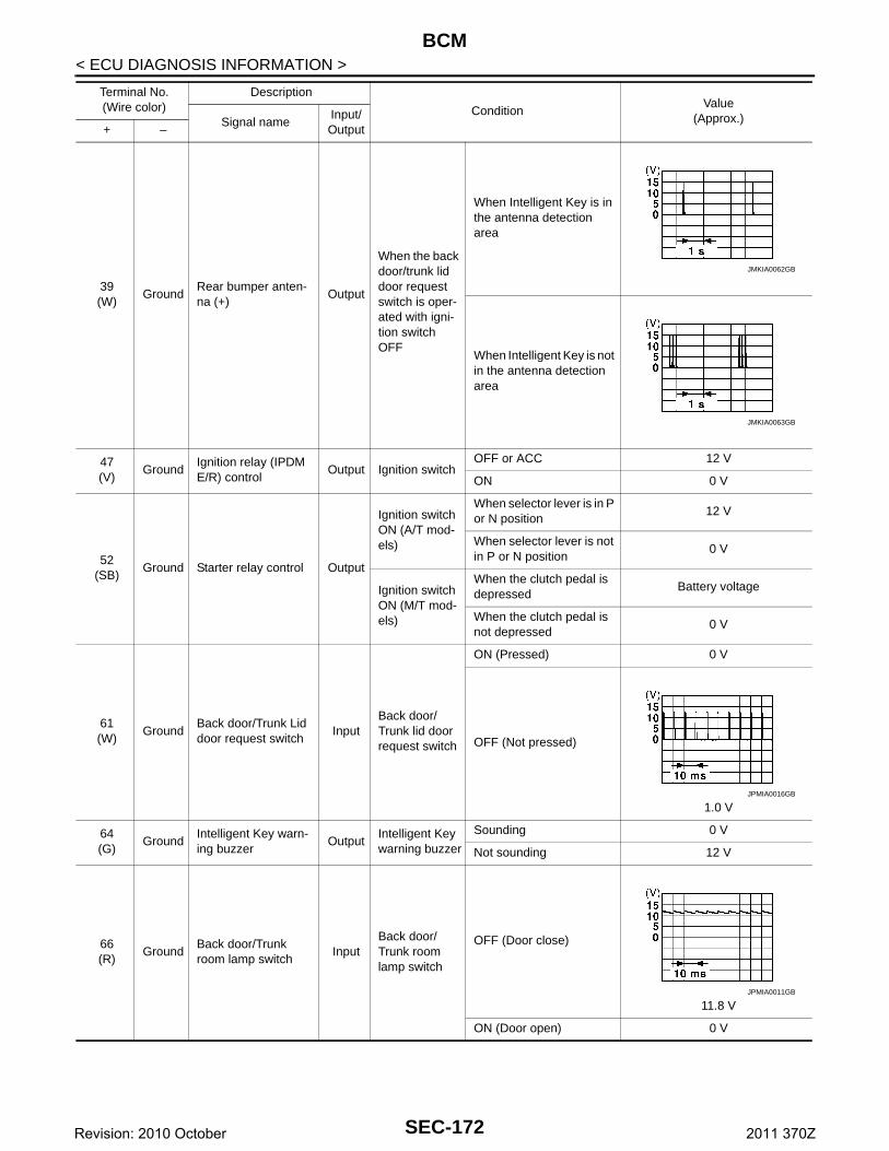
BCM
< ECU DIAGNOSIS INFORMATION >39(W)
GroundRear bumper anten-na (+)
Output
When the back door/trunk lid door request switch is oper-ated with igni-tion switch OFF
When Intelligent Key is in the antenna detection area
When Intelligent Key is not in the antenna detection area
47(V)
GroundIgnition relay (IPDM E/R) control
Output Ignition switchOFF or ACC 12 V
ON 0 V
52(SB)
Ground Starter relay control Output
Ignition switch ON (A/T mod-els)
When selector lever is in P or N position
12 V
When selector lever is not in P or N position
0 V
Ignition switch ON (M/T mod-els)
When the clutch pedal is depressed
Battery voltage
When the clutch pedal is not depressed
0 V
61(W)
GroundBack door/Trunk Lid door request switch
InputBack door/Trunk lid door request switch
ON (Pressed) 0 V
OFF (Not pressed)
1.0 V
64(G)
GroundIntelligent Key warn-ing buzzer
OutputIntelligent Key warning buzzer
Sounding 0 V
Not sounding 12 V
66(R)
GroundBack door/Trunk room lamp switch
InputBack door/ Trunk room lamp switch
OFF (Door close)
11.8 V
ON (Door open) 0 V
Terminal No.(Wire color)
Description
ConditionValue
(Approx.)Signal nameInput/ Output+ –
JMKIA0062GB
JMKIA0063GB
JPMIA0016GB
JPMIA0011GB
SEC-172Revision: 2010 October 2011 370Z
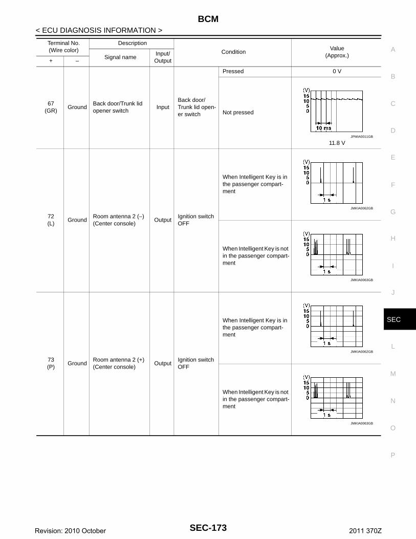
BCM
C
D
E
F
G
H
I
J
L
M
A
B
EC
N
O
P
< ECU DIAGNOSIS INFORMATION >
S
67(GR)
GroundBack door/Trunk lid opener switch
InputBack door/Trunk lid open-er switch
Pressed 0 V
Not pressed
11.8 V
72(L)
GroundRoom antenna 2 (−) (Center console)
OutputIgnition switch OFF
When Intelligent Key is in the passenger compart-ment
When Intelligent Key is not in the passenger compart-ment
73(P)
GroundRoom antenna 2 (+) (Center console)
OutputIgnition switch OFF
When Intelligent Key is in the passenger compart-ment
When Intelligent Key is not in the passenger compart-ment
Terminal No.(Wire color)
Description
ConditionValue
(Approx.)Signal nameInput/ Output+ –
JPMIA0011GB
JMKIA0062GB
JMKIA0063GB
JMKIA0062GB
JMKIA0063GB
SEC-173Revision: 2010 October 2011 370Z
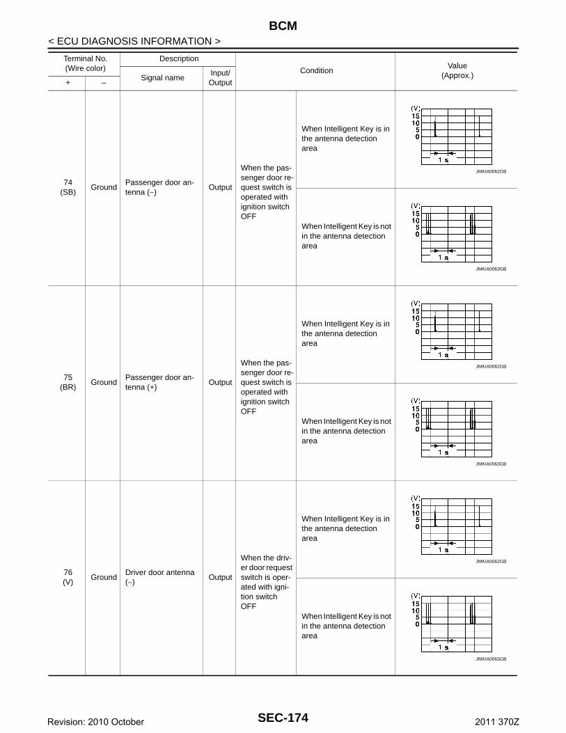
BCM
< ECU DIAGNOSIS INFORMATION >74(SB)
GroundPassenger door an-tenna (−)
Output
When the pas-senger door re-quest switch is operated with ignition switch OFF
When Intelligent Key is in the antenna detection area
When Intelligent Key is not in the antenna detection area
75(BR)
GroundPassenger door an-tenna (+)
Output
When the pas-senger door re-quest switch is operated with ignition switch OFF
When Intelligent Key is in the antenna detection area
When Intelligent Key is not in the antenna detection area
76(V)
GroundDriver door antenna (−)
Output
When the driv-er door request switch is oper-ated with igni-tion switch OFF
When Intelligent Key is in the antenna detection area
When Intelligent Key is not in the antenna detection area
Terminal No.(Wire color)
Description
ConditionValue
(Approx.)Signal nameInput/ Output+ –
JMKIA0062GB
JMKIA0063GB
JMKIA0062GB
JMKIA0063GB
JMKIA0062GB
JMKIA0063GB
SEC-174Revision: 2010 October 2011 370Z
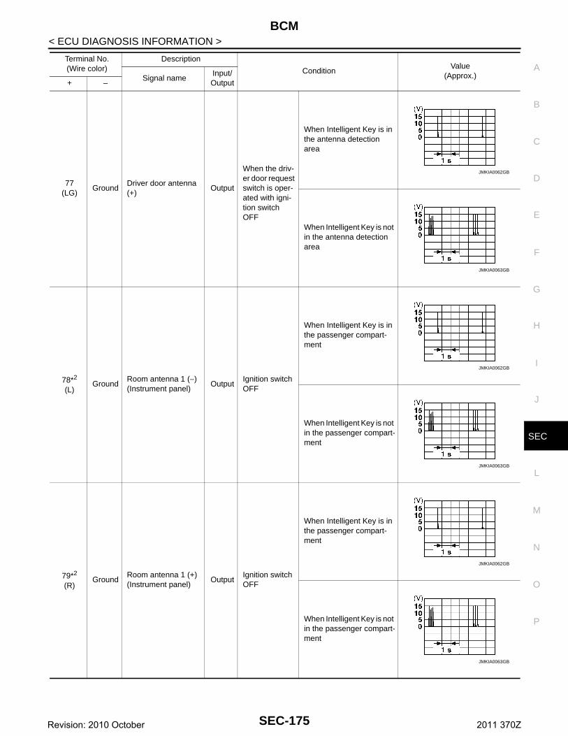
BCM
C
D
E
F
G
H
I
J
L
M
A
B
EC
N
O
P
< ECU DIAGNOSIS INFORMATION >
S
77(LG)
GroundDriver door antenna (+)
Output
When the driv-er door request switch is oper-ated with igni-tion switch OFF
When Intelligent Key is in the antenna detection area
When Intelligent Key is not in the antenna detection area
78*2
(L)Ground
Room antenna 1 (−) (Instrument panel)
OutputIgnition switch OFF
When Intelligent Key is in the passenger compart-ment
When Intelligent Key is not in the passenger compart-ment
79*2
(R)Ground
Room antenna 1 (+) (Instrument panel)
OutputIgnition switch OFF
When Intelligent Key is in the passenger compart-ment
When Intelligent Key is not in the passenger compart-ment
Terminal No.(Wire color)
Description
ConditionValue
(Approx.)Signal nameInput/ Output+ –
JMKIA0062GB
JMKIA0063GB
JMKIA0062GB
JMKIA0063GB
JMKIA0062GB
JMKIA0063GB
SEC-175Revision: 2010 October 2011 370Z
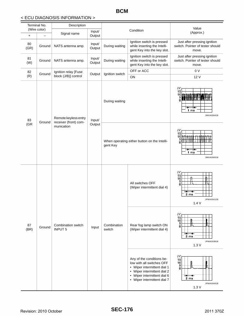
BCM
< ECU DIAGNOSIS INFORMATION >80(GR)
Ground NATS antenna amp.Input/Output
During waitingIgnition switch is pressed while inserting the Intelli-gent Key into the key slot.
Just after pressing ignition switch. Pointer of tester should
move.
81(W)
Ground NATS antenna amp.Input/Output
During waitingIgnition switch is pressed while inserting the Intelli-gent Key into the key slot.
Just after pressing ignition switch. Pointer of tester should
move.
82(R)
GroundIgnition relay [Fuse block (J/B)] control
Output Ignition switchOFF or ACC 0 V
ON 12 V
83(GR
GroundRemote keyless entry receiver (front) com-munication
Input/Output
During waiting
When operating either button on the Intelli-gent Key
87(BR)
GroundCombination switch INPUT 5
InputCombination switch
All switches OFF(Wiper intermittent dial 4)
1.4 V
Rear fog lamp switch ON(Wiper intermittent dial 4)
1.3 V
Any of the conditions be-low with all switches OFF• Wiper intermittent dial 1• Wiper intermittent dial 2• Wiper intermittent dial 6• Wiper intermittent dial 7
1.3 V
Terminal No.(Wire color)
Description
ConditionValue
(Approx.)Signal nameInput/ Output+ –
JMKIA0064GB
JMKIA0065GB
JPMIA0041GB
JPMIA0038GB
JPMIA0040GB
SEC-176Revision: 2010 October 2011 370Z
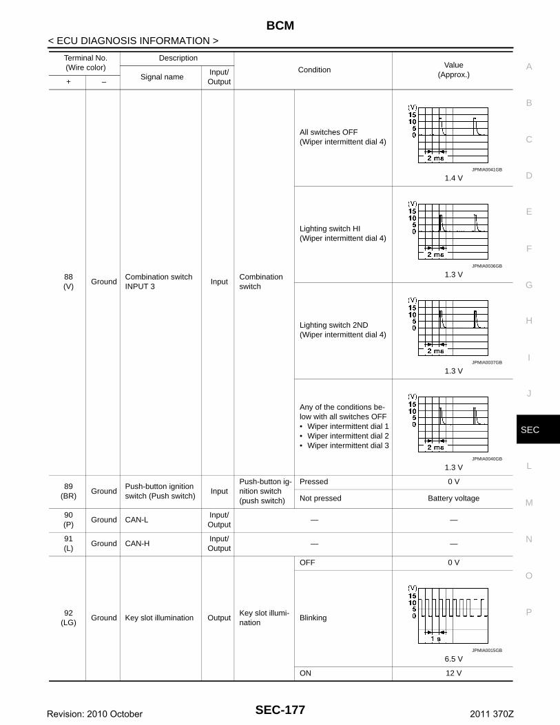
BCM
C
D
E
F
G
H
I
J
L
M
A
B
EC
N
O
P
< ECU DIAGNOSIS INFORMATION >
S
88(V)
GroundCombination switch INPUT 3
InputCombination switch
All switches OFF(Wiper intermittent dial 4)
1.4 V
Lighting switch HI(Wiper intermittent dial 4)
1.3 V
Lighting switch 2ND(Wiper intermittent dial 4)
1.3 V
Any of the conditions be-low with all switches OFF• Wiper intermittent dial 1• Wiper intermittent dial 2• Wiper intermittent dial 3
1.3 V
89(BR)
GroundPush-button ignition switch (Push switch)
InputPush-button ig-nition switch (push switch)
Pressed 0 V
Not pressed Battery voltage
90(P)
Ground CAN-LInput/ Output
— —
91(L)
Ground CAN-HInput/ Output
— —
92(LG)
Ground Key slot illumination OutputKey slot illumi-nation
OFF 0 V
Blinking
6.5 V
ON 12 V
Terminal No.(Wire color)
Description
ConditionValue
(Approx.)Signal nameInput/ Output+ –
JPMIA0041GB
JPMIA0036GB
JPMIA0037GB
JPMIA0040GB
JPMIA0015GB
SEC-177Revision: 2010 October 2011 370Z
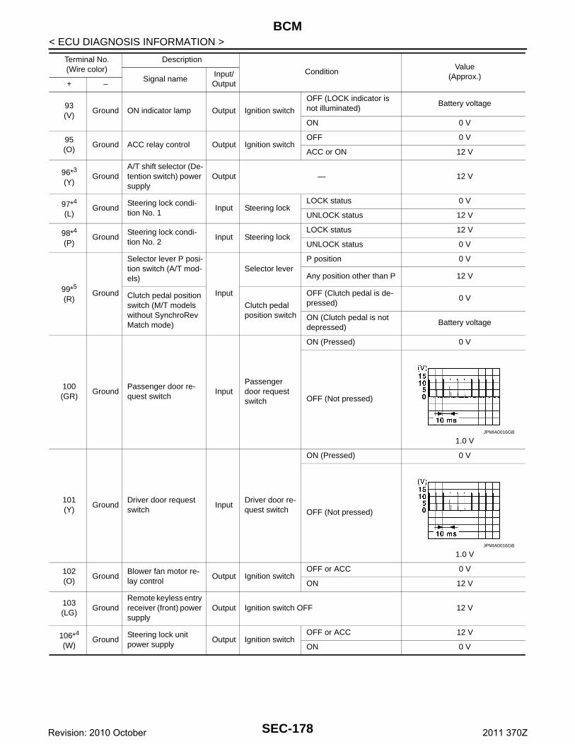
BCM
< ECU DIAGNOSIS INFORMATION >93(V)
Ground ON indicator lamp Output Ignition switch
OFF (LOCK indicator is not illuminated)
Battery voltage
ON 0 V
95(O)
Ground ACC relay control Output Ignition switchOFF 0 V
ACC or ON 12 V
96*3
(Y)Ground
A/T shift selector (De-tention switch) power supply
Output — 12 V
97*4
(L)Ground
Steering lock condi-tion No. 1
Input Steering lockLOCK status 0 V
UNLOCK status 12 V
98*4
(P)Ground
Steering lock condi-tion No. 2
Input Steering lockLOCK status 12 V
UNLOCK status 0 V
99*5
(R)Ground
Selector lever P posi-tion switch (A/T mod-els)
Input
Selector leverP position 0 V
Any position other than P 12 V
Clutch pedal position switch (M/T models without SynchroRev Match mode)
Clutch pedal position switch
OFF (Clutch pedal is de-pressed)
0 V
ON (Clutch pedal is not depressed)
Battery voltage
100(GR)
GroundPassenger door re-quest switch
InputPassenger door request switch
ON (Pressed) 0 V
OFF (Not pressed)
1.0 V
101(Y)
GroundDriver door request switch
InputDriver door re-quest switch
ON (Pressed) 0 V
OFF (Not pressed)
1.0 V
102(O)
GroundBlower fan motor re-lay control
Output Ignition switchOFF or ACC 0 V
ON 12 V
103(LG)
GroundRemote keyless entry receiver (front) power supply
Output Ignition switch OFF 12 V
106*4
(W)Ground
Steering lock unit power supply
Output Ignition switchOFF or ACC 12 V
ON 0 V
Terminal No.(Wire color)
Description
ConditionValue
(Approx.)Signal nameInput/ Output+ –
JPMIA0016GB
JPMIA0016GB
SEC-178Revision: 2010 October 2011 370Z
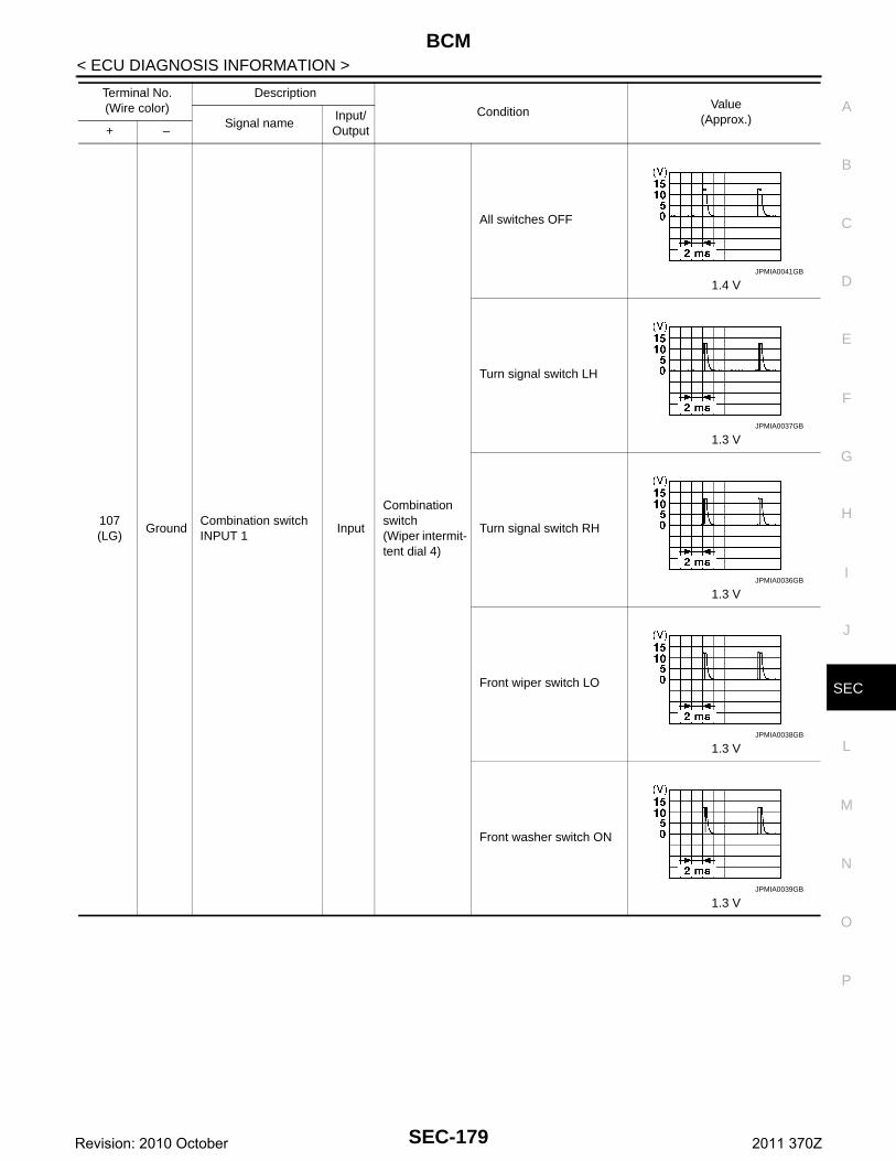
BCM
C
D
E
F
G
H
I
J
L
M
A
B
EC
N
O
P
< ECU DIAGNOSIS INFORMATION >
S
107(LG)
GroundCombination switch INPUT 1
Input
Combination switch(Wiper intermit-tent dial 4)
All switches OFF
1.4 V
Turn signal switch LH
1.3 V
Turn signal switch RH
1.3 V
Front wiper switch LO
1.3 V
Front washer switch ON
1.3 V
Terminal No.(Wire color)
Description
ConditionValue
(Approx.)Signal nameInput/ Output+ –
JPMIA0041GB
JPMIA0037GB
JPMIA0036GB
JPMIA0038GB
JPMIA0039GB
SEC-179Revision: 2010 October 2011 370Z
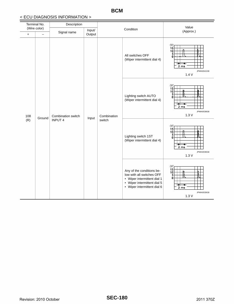
BCM
< ECU DIAGNOSIS INFORMATION >108(R)
GroundCombination switch INPUT 4
InputCombination switch
All switches OFF(Wiper intermittent dial 4)
1.4 V
Lighting switch AUTO(Wiper intermittent dial 4)
1.3 V
Lighting switch 1ST(Wiper intermittent dial 4)
1.3 V
Any of the conditions be-low with all switches OFF• Wiper intermittent dial 1• Wiper intermittent dial 5• Wiper intermittent dial 6
1.3 V
Terminal No.(Wire color)
Description
ConditionValue
(Approx.)Signal nameInput/ Output+ –
JPMIA0041GB
JPMIA0038GB
JPMIA0036GB
JPMIA0039GB
SEC-180Revision: 2010 October 2011 370Z
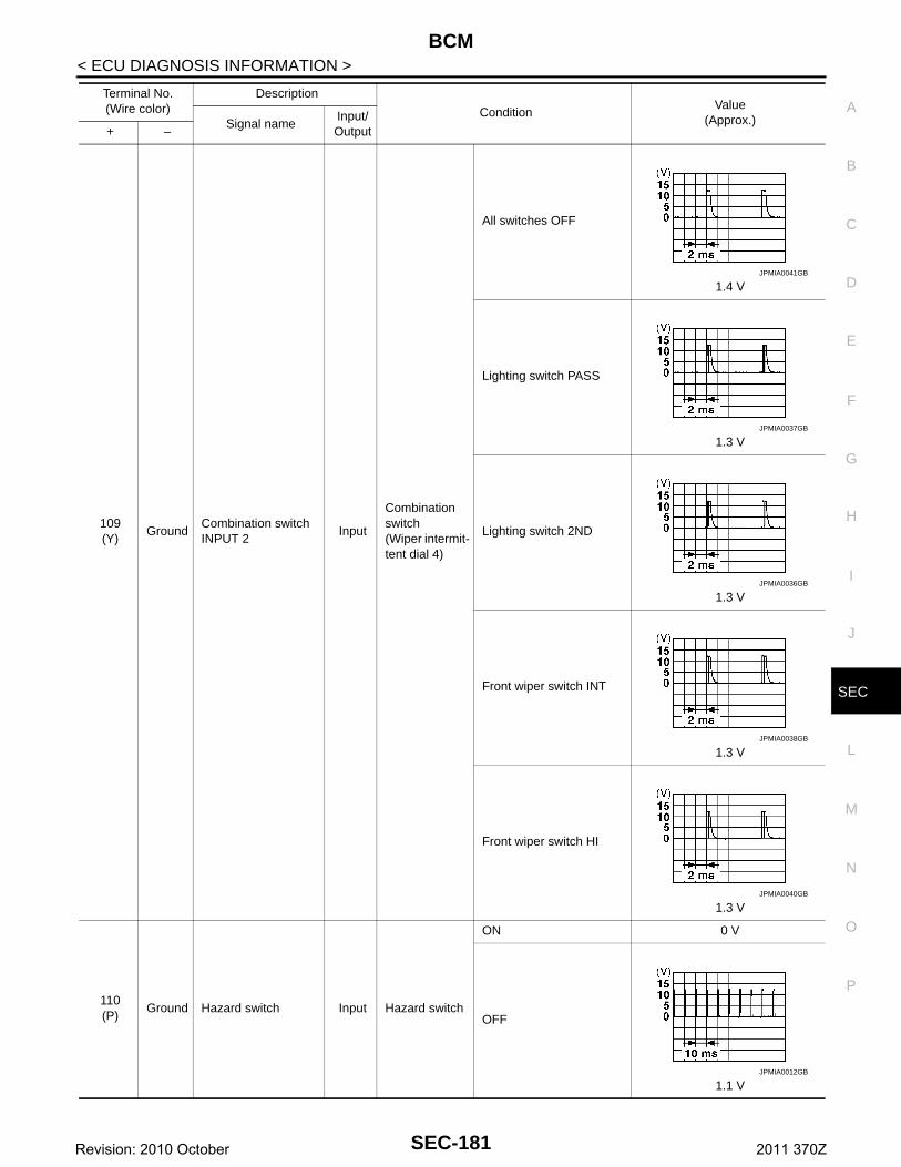
BCM
C
D
E
F
G
H
I
J
L
M
A
B
EC
N
O
P
< ECU DIAGNOSIS INFORMATION >
S
109(Y)
GroundCombination switch INPUT 2
Input
Combination switch(Wiper intermit-tent dial 4)
All switches OFF
1.4 V
Lighting switch PASS
1.3 V
Lighting switch 2ND
1.3 V
Front wiper switch INT
1.3 V
Front wiper switch HI
1.3 V
110(P)
Ground Hazard switch Input Hazard switch
ON 0 V
OFF
1.1 V
Terminal No.(Wire color)
Description
ConditionValue
(Approx.)Signal nameInput/ Output+ –
JPMIA0041GB
JPMIA0037GB
JPMIA0036GB
JPMIA0038GB
JPMIA0040GB
JPMIA0012GB
SEC-181Revision: 2010 October 2011 370Z
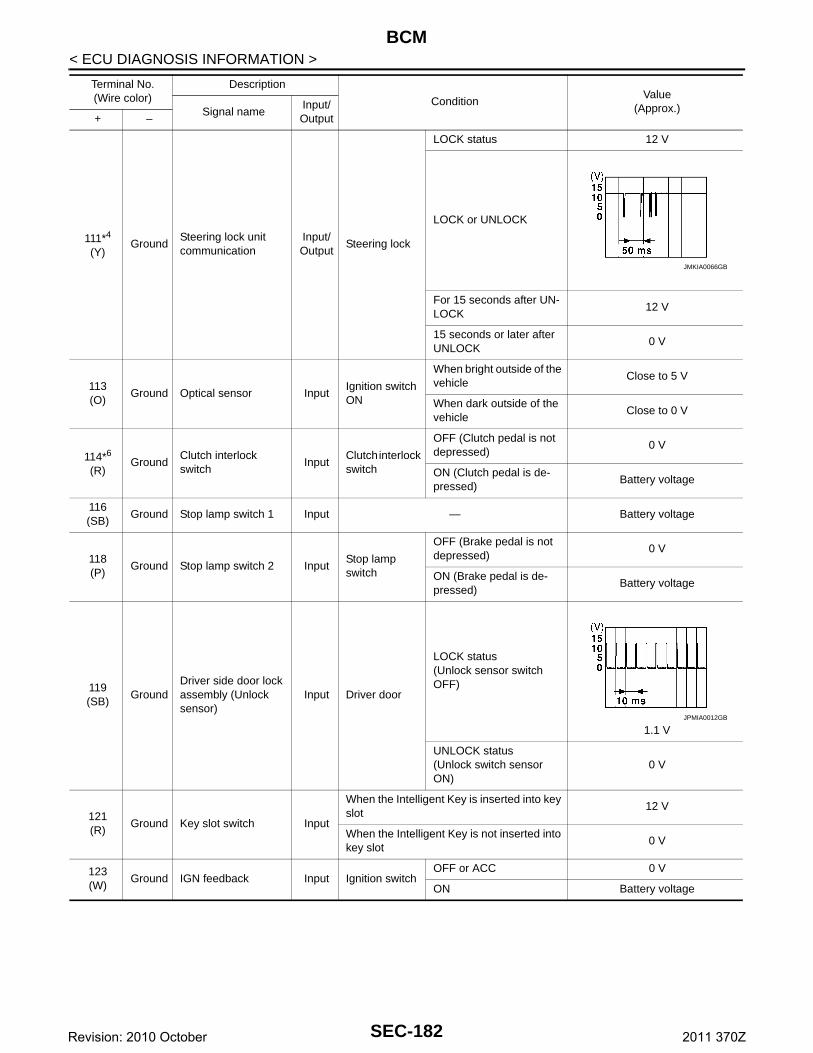
BCM
< ECU DIAGNOSIS INFORMATION >111*4
(Y)Ground
Steering lock unit communication
Input/Output
Steering lock
LOCK status 12 V
LOCK or UNLOCK
For 15 seconds after UN-LOCK
12 V
15 seconds or later after UNLOCK
0 V
113(O)
Ground Optical sensor InputIgnition switch ON
When bright outside of the vehicle
Close to 5 V
When dark outside of the vehicle
Close to 0 V
114*6
(R)Ground
Clutch interlock switch
InputClutch interlock switch
OFF (Clutch pedal is not depressed)
0 V
ON (Clutch pedal is de-pressed)
Battery voltage
116(SB)
Ground Stop lamp switch 1 Input — Battery voltage
118(P)
Ground Stop lamp switch 2 InputStop lamp switch
OFF (Brake pedal is not depressed)
0 V
ON (Brake pedal is de-pressed)
Battery voltage
119(SB)
GroundDriver side door lock assembly (Unlock sensor)
Input Driver door
LOCK status(Unlock sensor switch OFF)
1.1 V
UNLOCK status(Unlock switch sensor ON)
0 V
121(R)
Ground Key slot switch Input
When the Intelligent Key is inserted into key slot
12 V
When the Intelligent Key is not inserted into key slot
0 V
123(W)
Ground IGN feedback Input Ignition switchOFF or ACC 0 V
ON Battery voltage
Terminal No.(Wire color)
Description
ConditionValue
(Approx.)Signal nameInput/ Output+ –
JMKIA0066GB
JPMIA0012GB
SEC-182Revision: 2010 October 2011 370Z
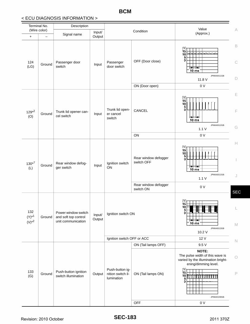
BCM
C
D
E
F
G
H
I
J
L
M
A
B
EC
N
O
P
< ECU DIAGNOSIS INFORMATION >
S
124(LG)
GroundPassenger door switch
InputPassenger door switch
OFF (Door close)
11.8 V
ON (Door open) 0 V
129*2
(O)Ground
Trunk lid opener can-cel switch
InputTrunk lid open-er cancel switch
CANCEL
1.1 V
ON 0 V
130*7
(L)Ground
Rear window defog-ger switch
InputIgnition switch ON
Rear window defogger switch OFF
1.1 V
Rear window defogger switch ON
0 V
132
(Y)*1
(V)*2Ground
Power window switch and soft top control unit communication
Input/Output
Ignition switch ON
10.2 V
Ignition switch OFF or ACC 12 V
133(G)
GroundPush-button ignition switch illumination
OutputPush-button ig-nition switch il-lumination
ON (Tail lamps OFF) 9.5 V
ON (Tail lamps ON)
NOTE:The pulse width of this wave is
varied by the illumination bright-ening/dimming level.
OFF 0 V
Terminal No.(Wire color)
Description
ConditionValue
(Approx.)Signal nameInput/ Output+ –
JPMIA0011GB
JPMIA0012GB
JPMIA0012GB
JPMIA0013GB
JPMIA0159GB
SEC-183Revision: 2010 October 2011 370Z
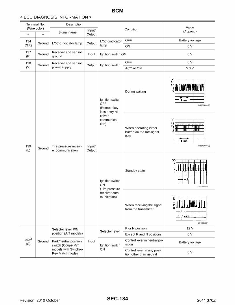
BCM
< ECU DIAGNOSIS INFORMATION >134(GR)
Ground LOCK indicator lamp OutputLOCK indicator lamp
OFF Battery voltage
ON 0 V
137(P)
GroundReceiver and sensor ground
Input Ignition switch ON 0 V
138(V)
GroundReceiver and sensor power supply
Output Ignition switchOFF 0 V
ACC or ON 5.0 V
139(L)
GroundTire pressure receiv-er communication
Input/Output
Ignition switch OFF(Remote key-less entry re-ceiver communica-tion)
During waiting
When operating either button on the Intelligent Key
Ignition switch ON(Tire pressure receiver com-munication)
Standby state
When receiving the signal from the transmitter
140*8
(G)Ground
Selector lever P/N position (A/T models)
Input
Selector leverP or N position 12 V
Except P and N positions 0 V
Park/neutral position switch (Coupe M/T models with Synchro-Rev Match mode)
Ignition switch ON
Control lever in neutral po-sition
Battery voltage
Control lever in any posi-tion other than neutral
0 V
Terminal No.(Wire color)
Description
ConditionValue
(Approx.)Signal nameInput/ Output+ –
JMKIA0064GB
JMKIA0065GB
OCC3881D
OCC3880D
SEC-184Revision: 2010 October 2011 370Z
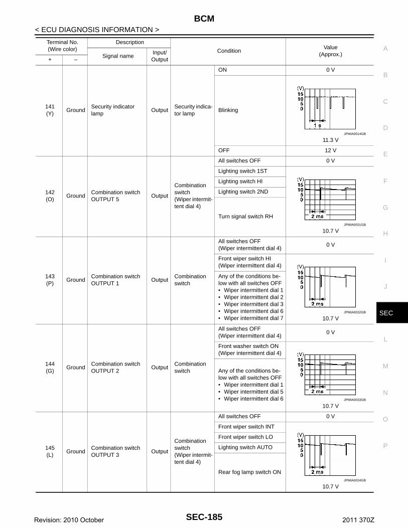
BCM
C
D
E
F
G
H
I
J
L
M
A
B
EC
N
O
P
< ECU DIAGNOSIS INFORMATION >
S
141(Y)
GroundSecurity indicator lamp
OutputSecurity indica-tor lamp
ON 0 V
Blinking
11.3 V
OFF 12 V
142(O)
GroundCombination switch OUTPUT 5
Output
Combination switch(Wiper intermit-tent dial 4)
All switches OFF 0 V
Lighting switch 1ST
10.7 V
Lighting switch HI
Lighting switch 2ND
Turn signal switch RH
143(P)
GroundCombination switch OUTPUT 1
OutputCombination switch
All switches OFF(Wiper intermittent dial 4)
0 V
Front wiper switch HI(Wiper intermittent dial 4)
10.7 V
Any of the conditions be-low with all switches OFF• Wiper intermittent dial 1• Wiper intermittent dial 2• Wiper intermittent dial 3• Wiper intermittent dial 6• Wiper intermittent dial 7
144(G)
GroundCombination switch OUTPUT 2
OutputCombination switch
All switches OFF(Wiper intermittent dial 4)
0 V
Front washer switch ON(Wiper intermittent dial 4)
10.7 V
Any of the conditions be-low with all switches OFF• Wiper intermittent dial 1• Wiper intermittent dial 5• Wiper intermittent dial 6
145(L)
GroundCombination switch OUTPUT 3
Output
Combination switch(Wiper intermit-tent dial 4)
All switches OFF 0 V
Front wiper switch INT
10.7 V
Front wiper switch LO
Lighting switch AUTO
Rear fog lamp switch ON
Terminal No.(Wire color)
Description
ConditionValue
(Approx.)Signal nameInput/ Output+ –
JPMIA0014GB
JPMIA0031GB
JPMIA0032GB
JPMIA0033GB
JPMIA0034GB
SEC-185Revision: 2010 October 2011 370Z
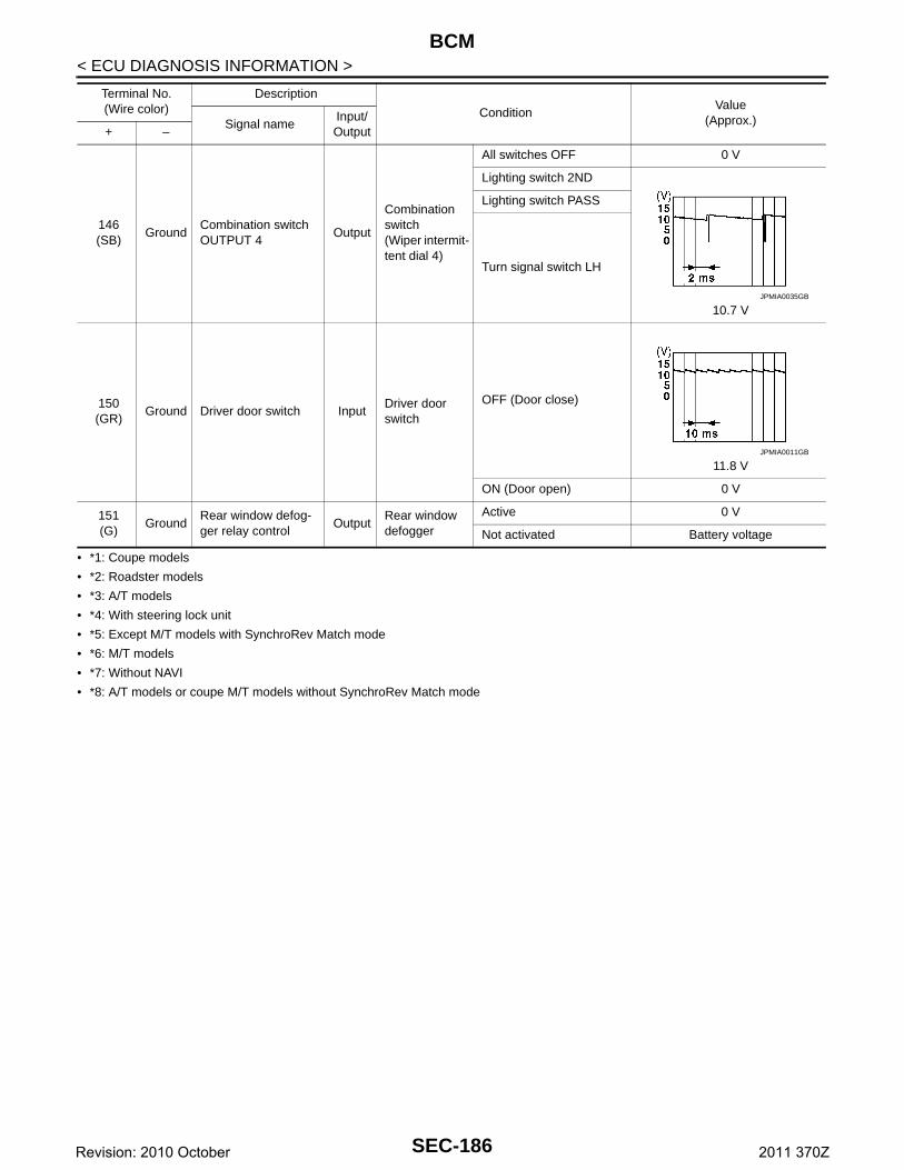
BCM
< ECU DIAGNOSIS INFORMATION >• *1: Coupe models
• *2: Roadster models
• *3: A/T models
• *4: With steering lock unit
• *5: Except M/T models with SynchroRev Match mode
• *6: M/T models
• *7: Without NAVI
• *8: A/T models or coupe M/T models without SynchroRev Match mode
146(SB)
GroundCombination switch OUTPUT 4
Output
Combination switch(Wiper intermit-tent dial 4)
All switches OFF 0 V
Lighting switch 2ND
10.7 V
Lighting switch PASS
Turn signal switch LH
150(GR)
Ground Driver door switch InputDriver door switch
OFF (Door close)
11.8 V
ON (Door open) 0 V
151(G)
GroundRear window defog-ger relay control
OutputRear window defogger
Active 0 V
Not activated Battery voltage
Terminal No.(Wire color)
Description
ConditionValue
(Approx.)Signal nameInput/ Output+ –
JPMIA0035GB
JPMIA0011GB
SEC-186Revision: 2010 October 2011 370Z
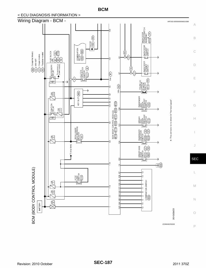
BCM
C
D
E
F
G
H
I
J
L
M
A
B
EC
N
O
P
< ECU DIAGNOSIS INFORMATION >
S
Wiring Diagram - BCM - INFOID:0000000006921588
JCMWA6293GB
SEC-187Revision: 2010 October 2011 370Z
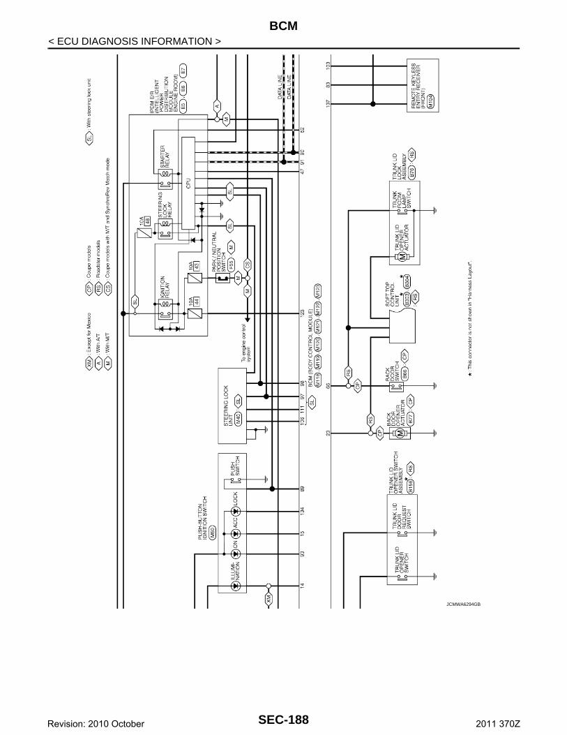
BCM
< ECU DIAGNOSIS INFORMATION >JCMWA6294GB
SEC-188Revision: 2010 October 2011 370Z
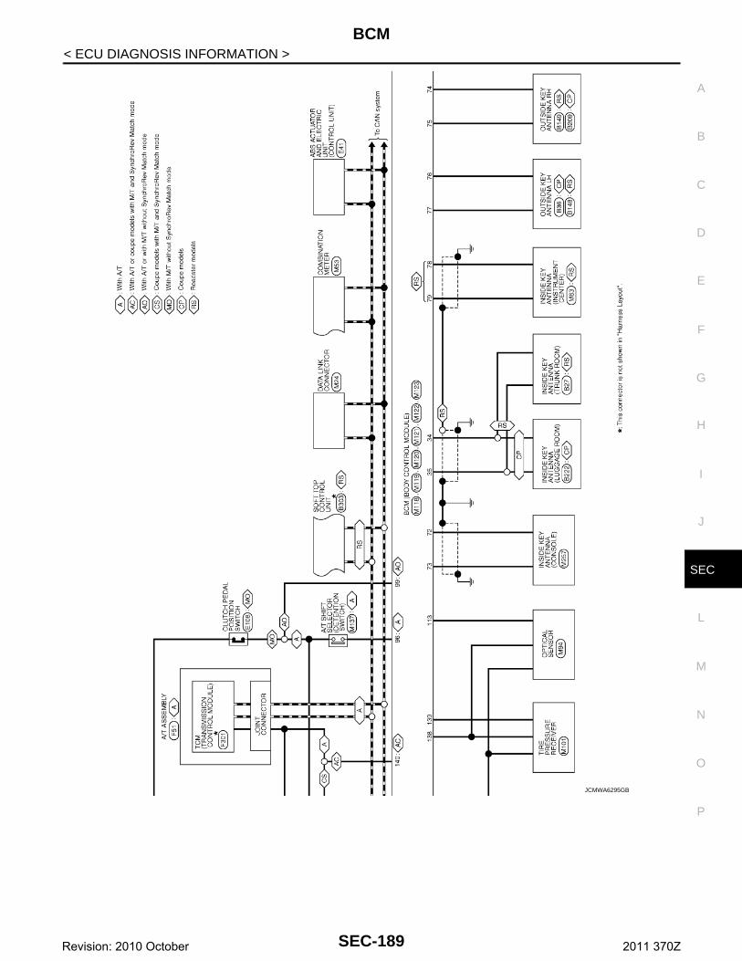
BCM
C
D
E
F
G
H
I
J
L
M
A
B
EC
N
O
P
< ECU DIAGNOSIS INFORMATION >
S
JCMWA6295GB
SEC-189Revision: 2010 October 2011 370Z
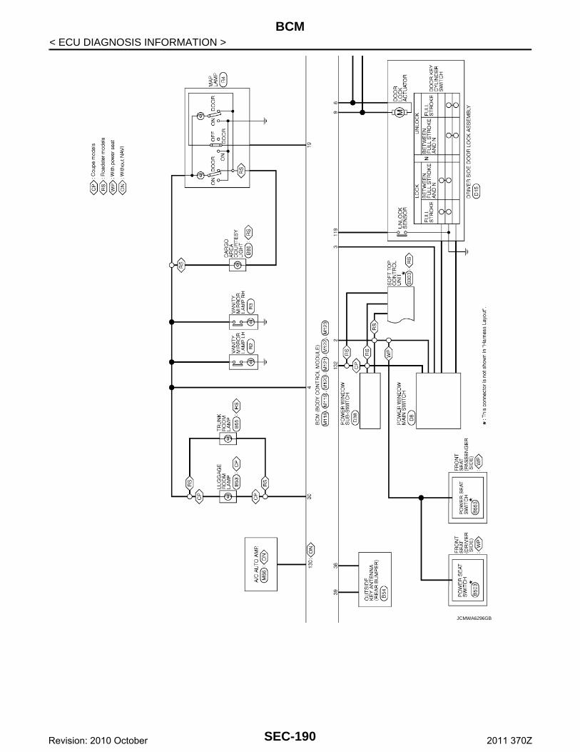
BCM
< ECU DIAGNOSIS INFORMATION >JCMWA6296GB
SEC-190Revision: 2010 October 2011 370Z
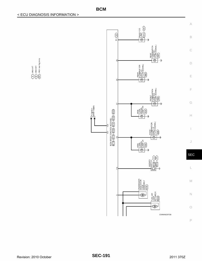
BCM
C
D
E
F
G
H
I
J
L
M
A
B
EC
N
O
P
< ECU DIAGNOSIS INFORMATION >
S
JCMWA6297GB
SEC-191Revision: 2010 October 2011 370Z
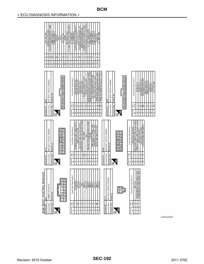
BCM
< ECU DIAGNOSIS INFORMATION >JCMWA6298GB
SEC-192Revision: 2010 October 2011 370Z
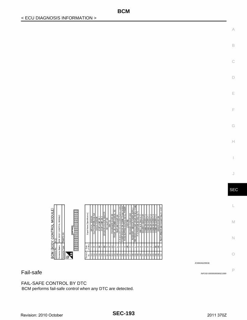
BCM
C
D
E
F
G
H
I
J
L
M
A
B
EC
N
O
P
< ECU DIAGNOSIS INFORMATION >
S
Fail-safe INFOID:0000000006921589
FAIL-SAFE CONTROL BY DTCBCM performs fail-safe control when any DTC are detected.
JCMWA6299GB
SEC-193Revision: 2010 October 2011 370Z
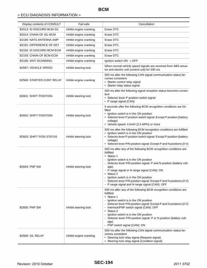
BCM
< ECU DIAGNOSIS INFORMATION >Display contents of CONSULT Fail-safe Cancellation
B2013: ID DISCORD BCM-S/L Inhibit engine cranking Erase DTC
B2014: CHAIN OF S/L-BCM Inhibit engine cranking Erase DTC
B2190: NATS ANTENNA AMP Inhibit engine cranking Erase DTC
B2191: DIFFERENCE OF KEY Inhibit engine cranking Erase DTC
B2192: ID DISCORD BCM-ECM Inhibit engine cranking Erase DTC
B2193: CHAIN OF BCM-ECM Inhibit engine cranking Erase DTC
B2195: ANTI SCANNING Inhibit engine cranking Ignition switch ON → OFF
B2557: VEHICLE SPEED Inhibit steering lockWhen normal vehicle speed signals are received from ABS actua-tor and electric unit (control unit) for 500 ms
B2560: STARTER CONT RELAY Inhibit engine cranking
500 ms after the following CAN signal communication status be-comes consistent• Starter control relay signal• Starter relay status signal
B2601: SHIFT POSITION Inhibit steering lock
500 ms after the following signal reception status becomes consis-tent• Selector lever P position switch signal• P range signal (CAN)
B2602: SHIFT POSITION Inhibit steering lock
5 seconds after the following BCM recognition conditions are ful-filled• Ignition switch is in the ON position• Selector lever P position switch signal: Except P position (battery
voltage)• Vehicle speed: 4 km/h (2.5 MPH) or more
B2603: SHIFT POSI STATUS Inhibit steering lock
500 ms after the following BCM recognition conditions are fulfilled• Ignition switch is in the ON position• Selector lever P position switch signal: Except P position (battery
voltage)• Selector lever P/N position signal: Except P and N positions (0 V)
B2604: PNP SW Inhibit steering lock
500 ms after any of the following BCM recognition conditions are fulfilled• Status 1- Ignition switch is in the ON position- Selector lever P/N position signal: P and N position (battery volt-
age)- P range signal or N range signal (CAN): ON• Status 2- Ignition switch is in the ON position- Selector lever P/N position signal: Except P and N positions (0 V)- P range signal and N range signal (CAN): OFF
B2605: PNP SW Inhibit steering lock
500 ms after any of the following BCM recognition conditions are fulfilled• Status 1- Ignition switch is in the ON position- Selector lever P/N position signal: Except P and N positions (0 V)- Interlock/PNP switch signal (CAN): OFF• Status 2- Ignition switch is in the ON position- Selector lever P/N position signal: P or N position (battery volt-
age)- PNP switch signal (CAN): ON
B2606: S/L RELAY Inhibit engine cranking
500 ms after the following CAN signal communication status be-comes consistent• Steering lock relay signal (Request signal)• Steering lock relay signal (Condition signal)
SEC-194Revision: 2010 October 2011 370Z
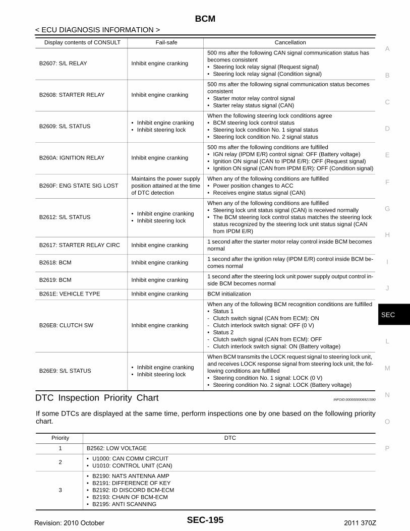
BCM
C
D
E
F
G
H
I
J
L
M
A
B
EC
N
O
P
< ECU DIAGNOSIS INFORMATION >
S
DTC Inspection Priority Chart INFOID:0000000006921590
If some DTCs are displayed at the same time, perform inspections one by one based on the following prioritychart.
B2607: S/L RELAY Inhibit engine cranking
500 ms after the following CAN signal communication status has becomes consistent• Steering lock relay signal (Request signal)• Steering lock relay signal (Condition signal)
B2608: STARTER RELAY Inhibit engine cranking
500 ms after the following signal communication status becomes consistent• Starter motor relay control signal• Starter relay status signal (CAN)
B2609: S/L STATUS• Inhibit engine cranking• Inhibit steering lock
When the following steering lock conditions agree• BCM steering lock control status• Steering lock condition No. 1 signal status• Steering lock condition No. 2 signal status
B260A: IGNITION RELAY Inhibit engine cranking
500 ms after the following conditions are fulfilled• IGN relay (IPDM E/R) control signal: OFF (Battery voltage)• Ignition ON signal (CAN to IPDM E/R): OFF (Request signal)• Ignition ON signal (CAN from IPDM E/R): OFF (Condition signal)
B260F: ENG STATE SIG LOSTMaintains the power supply position attained at the time of DTC detection
When any of the following conditions are fulfilled• Power position changes to ACC• Receives engine status signal (CAN)
B2612: S/L STATUS• Inhibit engine cranking• Inhibit steering lock
When any of the following conditions are fulfilled• Steering lock unit status signal (CAN) is received normally• The BCM steering lock control status matches the steering lock
status recognized by the steering lock unit status signal (CAN from IPDM E/R)
B2617: STARTER RELAY CIRC Inhibit engine cranking1 second after the starter motor relay control inside BCM becomes normal
B2618: BCM Inhibit engine cranking1 second after the ignition relay (IPDM E/R) control inside BCM be-comes normal
B2619: BCM Inhibit engine cranking1 second after the steering lock unit power supply output control in-side BCM becomes normal
B261E: VEHICLE TYPE Inhibit engine cranking BCM initialization
B26E8: CLUTCH SW Inhibit engine cranking
When any of the following BCM recognition conditions are fulfilled• Status 1- Clutch switch signal (CAN from ECM): ON- Clutch interlock switch signal: OFF (0 V)• Status 2- Clutch switch signal (CAN from ECM): OFF- Clutch interlock switch signal: ON (Battery voltage)
B26E9: S/L STATUS• Inhibit engine cranking• Inhibit steering lock
When BCM transmits the LOCK request signal to steering lock unit, and receives LOCK response signal from steering lock unit, the fol-lowing conditions are fulfilled• Steering condition No. 1 signal: LOCK (0 V)• Steering condition No. 2 signal: LOCK (Battery voltage)
Display contents of CONSULT Fail-safe Cancellation
Priority DTC
1 B2562: LOW VOLTAGE
2• U1000: CAN COMM CIRCUIT• U1010: CONTROL UNIT (CAN)
3
• B2190: NATS ANTENNA AMP• B2191: DIFFERENCE OF KEY• B2192: ID DISCORD BCM-ECM• B2193: CHAIN OF BCM-ECM• B2195: ANTI SCANNING
SEC-195Revision: 2010 October 2011 370Z
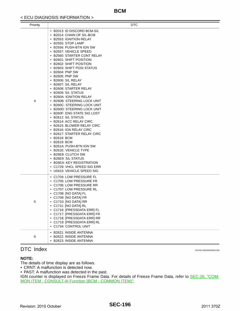
BCM
< ECU DIAGNOSIS INFORMATION >DTC Index INFOID:0000000006921591
NOTE:The details of time display are as follows.• CRNT: A malfunction is detected now.• PAST: A malfunction was detected in the past.IGN counter is displayed on Freeze Frame Data. For details of Freeze Frame Data, refer to SEC-26, "COM-MON ITEM : CONSULT-III Function (BCM - COMMON ITEM)".
4
• B2013: ID DISCORD BCM-S/L• B2014: CHAIN OF S/L-BCM• B2553: IGNITION RELAY• B2555: STOP LAMP • B2556: PUSH-BTN IGN SW• B2557: VEHICLE SPEED• B2560: STARTER CONT RELAY• B2601: SHIFT POSITION• B2602: SHIFT POSITION• B2603: SHIFT POSI STATUS• B2604: PNP SW• B2605: PNP SW• B2606: S/L RELAY• B2607: S/L RELAY• B2608: STARTER RELAY• B2609: S/L STATUS• B260A: IGNITION RELAY• B260B: STEERING LOCK UNIT• B260C: STEERING LOCK UNIT• B260D: STEERING LOCK UNIT• B260F: ENG STATE SIG LOST• B2612: S/L STATUS• B2614: ACC RELAY CIRC• B2615: BLOWER RELAY CIRC• B2616: IGN RELAY CIRC• B2617: STARTER RELAY CIRC• B2618: BCM• B2619: BCM• B261A: PUSH-BTN IGN SW• B261E: VEHICLE TYPE• B26E8: CLUTCH SW• B26E9: S/L STATUS• B26EA: KEY REGISTRATION• C1729: VHCL SPEED SIG ERR• U0415: VEHICLE SPEED SIG
5
• C1704: LOW PRESSURE FL• C1705: LOW PRESSURE FR• C1706: LOW PRESSURE RR• C1707: LOW PRESSURE RL• C1708: [NO DATA] FL• C1709: [NO DATA] FR• C1710: [NO DATA] RR• C1711: [NO DATA] RL• C1716: [PRESSDATA ERR] FL• C1717: [PRESSDATA ERR] FR• C1718: [PRESSDATA ERR] RR• C1719: [PRESSDATA ERR] RL• C1734: CONTROL UNIT
6• B2621: INSIDE ANTENNA • B2622: INSIDE ANTENNA • B2623: INSIDE ANTENNA
Priority DTC
SEC-196Revision: 2010 October 2011 370Z
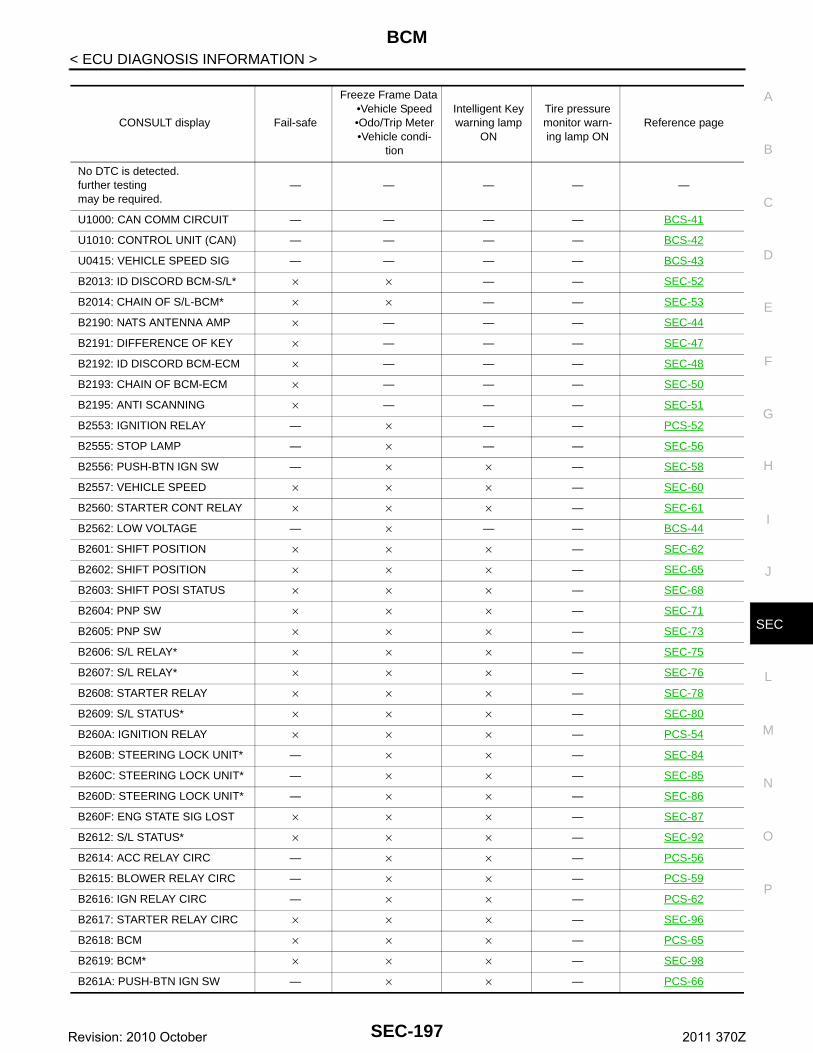
BCM
C
D
E
F
G
H
I
J
L
M
A
B
EC
N
O
P
< ECU DIAGNOSIS INFORMATION >
S
CONSULT display Fail-safe
Freeze Frame Data•Vehicle Speed•Odo/Trip Meter•Vehicle condi-
tion
Intelligent Key warning lamp
ON
Tire pressure monitor warn-ing lamp ON
Reference page
No DTC is detected.further testingmay be required.
— — — — —
U1000: CAN COMM CIRCUIT — — — — BCS-41
U1010: CONTROL UNIT (CAN) — — — — BCS-42
U0415: VEHICLE SPEED SIG — — — — BCS-43
B2013: ID DISCORD BCM-S/L* × × — — SEC-52
B2014: CHAIN OF S/L-BCM* × × — — SEC-53
B2190: NATS ANTENNA AMP × — — — SEC-44
B2191: DIFFERENCE OF KEY × — — — SEC-47
B2192: ID DISCORD BCM-ECM × — — — SEC-48
B2193: CHAIN OF BCM-ECM × — — — SEC-50
B2195: ANTI SCANNING × — — — SEC-51
B2553: IGNITION RELAY — × — — PCS-52
B2555: STOP LAMP — × — — SEC-56
B2556: PUSH-BTN IGN SW — × × — SEC-58
B2557: VEHICLE SPEED × × × — SEC-60
B2560: STARTER CONT RELAY × × × — SEC-61
B2562: LOW VOLTAGE — × — — BCS-44
B2601: SHIFT POSITION × × × — SEC-62
B2602: SHIFT POSITION × × × — SEC-65
B2603: SHIFT POSI STATUS × × × — SEC-68
B2604: PNP SW × × × — SEC-71
B2605: PNP SW × × × — SEC-73
B2606: S/L RELAY* × × × — SEC-75
B2607: S/L RELAY* × × × — SEC-76
B2608: STARTER RELAY × × × — SEC-78
B2609: S/L STATUS* × × × — SEC-80
B260A: IGNITION RELAY × × × — PCS-54
B260B: STEERING LOCK UNIT* — × × — SEC-84
B260C: STEERING LOCK UNIT* — × × — SEC-85
B260D: STEERING LOCK UNIT* — × × — SEC-86
B260F: ENG STATE SIG LOST × × × — SEC-87
B2612: S/L STATUS* × × × — SEC-92
B2614: ACC RELAY CIRC — × × — PCS-56
B2615: BLOWER RELAY CIRC — × × — PCS-59
B2616: IGN RELAY CIRC — × × — PCS-62
B2617: STARTER RELAY CIRC × × × — SEC-96
B2618: BCM × × × — PCS-65
B2619: BCM* × × × — SEC-98
B261A: PUSH-BTN IGN SW — × × — PCS-66
SEC-197Revision: 2010 October 2011 370Z
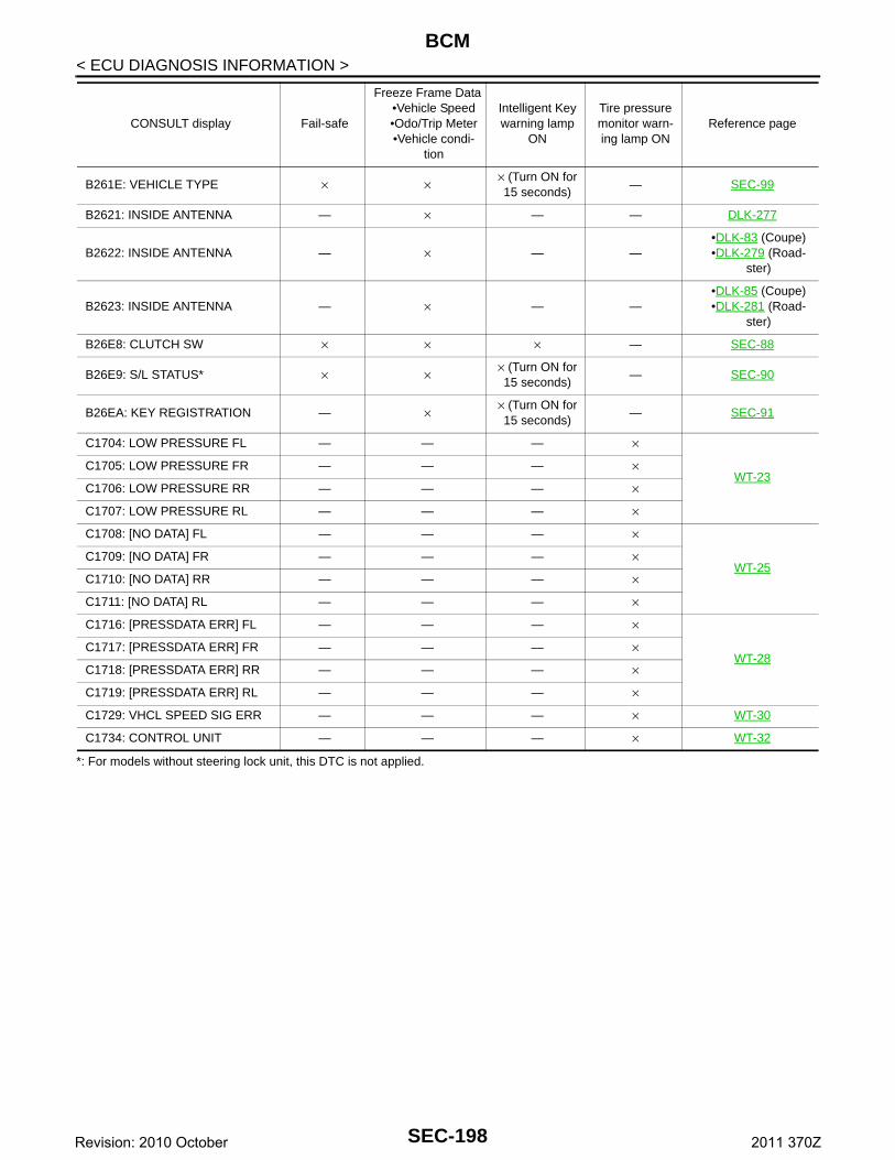
BCM
< ECU DIAGNOSIS INFORMATION >*: For models without steering lock unit, this DTC is not applied.
B261E: VEHICLE TYPE × × × (Turn ON for 15 seconds)
— SEC-99
B2621: INSIDE ANTENNA — × — — DLK-277
B2622: INSIDE ANTENNA — × — —•DLK-83 (Coupe)•DLK-279 (Road-
ster)
B2623: INSIDE ANTENNA — × — —•DLK-85 (Coupe)•DLK-281 (Road-
ster)
B26E8: CLUTCH SW × × × — SEC-88
B26E9: S/L STATUS* × × × (Turn ON for 15 seconds)
— SEC-90
B26EA: KEY REGISTRATION — × × (Turn ON for 15 seconds)
— SEC-91
C1704: LOW PRESSURE FL — — — ×
WT-23C1705: LOW PRESSURE FR — — — ×
C1706: LOW PRESSURE RR — — — ×
C1707: LOW PRESSURE RL — — — ×
C1708: [NO DATA] FL — — — ×
WT-25C1709: [NO DATA] FR — — — ×
C1710: [NO DATA] RR — — — ×
C1711: [NO DATA] RL — — — ×
C1716: [PRESSDATA ERR] FL — — — ×
WT-28C1717: [PRESSDATA ERR] FR — — — ×
C1718: [PRESSDATA ERR] RR — — — ×
C1719: [PRESSDATA ERR] RL — — — ×
C1729: VHCL SPEED SIG ERR — — — × WT-30
C1734: CONTROL UNIT — — — × WT-32
CONSULT display Fail-safe
Freeze Frame Data•Vehicle Speed•Odo/Trip Meter•Vehicle condi-
tion
Intelligent Key warning lamp
ON
Tire pressure monitor warn-ing lamp ON
Reference page
SEC-198Revision: 2010 October 2011 370Z
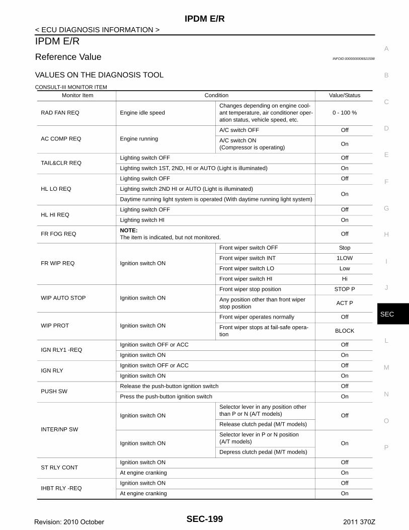
IPDM E/R
C
D
E
F
G
H
I
J
L
M
A
B
EC
N
O
P
< ECU DIAGNOSIS INFORMATION >
S
IPDM E/R
Reference Value INFOID:0000000006921598
VALUES ON THE DIAGNOSIS TOOL
CONSULT-III MONITOR ITEM
Monitor Item Condition Value/Status
RAD FAN REQ Engine idle speedChanges depending on engine cool-ant temperature, air conditioner oper-ation status, vehicle speed, etc.
0 - 100 %
AC COMP REQ Engine running
A/C switch OFF Off
A/C switch ON(Compressor is operating)
On
TAIL&CLR REQLighting switch OFF Off
Lighting switch 1ST, 2ND, HI or AUTO (Light is illuminated) On
HL LO REQ
Lighting switch OFF Off
Lighting switch 2ND HI or AUTO (Light is illuminated)On
Daytime running light system is operated (With daytime running light system)
HL HI REQLighting switch OFF Off
Lighting switch HI On
FR FOG REQNOTE:The item is indicated, but not monitored.
Off
FR WIP REQ Ignition switch ON
Front wiper switch OFF Stop
Front wiper switch INT 1LOW
Front wiper switch LO Low
Front wiper switch HI Hi
WIP AUTO STOP Ignition switch ON
Front wiper stop position STOP P
Any position other than front wiper stop position
ACT P
WIP PROT Ignition switch ON
Front wiper operates normally Off
Front wiper stops at fail-safe opera-tion
BLOCK
IGN RLY1 -REQIgnition switch OFF or ACC Off
Ignition switch ON On
IGN RLYIgnition switch OFF or ACC Off
Ignition switch ON On
PUSH SWRelease the push-button ignition switch Off
Press the push-button ignition switch On
INTER/NP SW
Ignition switch ON
Selector lever in any position other than P or N (A/T models) Off
Release clutch pedal (M/T models)
Ignition switch ON
Selector lever in P or N position(A/T models) On
Depress clutch pedal (M/T models)
ST RLY CONTIgnition switch ON Off
At engine cranking On
IHBT RLY -REQIgnition switch ON Off
At engine cranking On
SEC-199Revision: 2010 October 2011 370Z
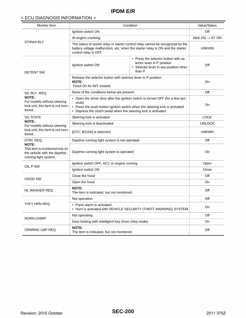
IPDM E/R
< ECU DIAGNOSIS INFORMATION >ST/INHI RLY
Ignition switch ON Off
At engine cranking INHI ON → ST ON
The status of starter relay or starter control relay cannot be recognized by the battery voltage malfunction, etc. when the starter relay is ON and the starter control relay is OFF
UNKWN
DETENT SW
Ignition switch ON
• Press the selector button with se-lector lever in P position
• Selector lever in any position other than P
Off
Release the selector button with selector lever in P positionNOTE: Fixed On for M/T models
On
S/L RLY -REQNOTE:For models without steering lock unit, this item is not mon-itored.
None of the conditions below are present Off
• Open the driver door after the ignition switch is turned OFF (for a few sec-onds)
• Press the push-button ignition switch when the steering lock is activated• Depress the clutch pedal when the steering lock is activated
On
S/L STATENOTE:For models without steering lock unit, this item is not mon-itored.
Steering lock is activated LOCK
Steering lock is deactivated UNLOCK
[DTC: B210A] is detected UNKWN
DTRL REQNOTE:This item is monitored only on the vehicle with the daytime running light system.
Daytime running light system is not operated Off
Daytime running light system is operated On
OIL P SWIgnition switch OFF, ACC or engine running Open
Ignition switch ON Close
HOOD SWClose the hood Off
Open the hood On
HL WASHER REQNOTE:The item is indicated, but not monitored.
Off
THFT HRN REQ
Not operation Off
• Panic alarm is activated• Horn is activated with VEHICLE SECURITY (THEFT WARNING) SYSTEM
On
HORN CHIRPNot operating Off
Door locking with Intelligent Key (horn chirp mode) On
CRNRNG LMP REQNOTE:The item is indicated, but not monitored.
Off
Monitor Item Condition Value/Status
SEC-200Revision: 2010 October 2011 370Z
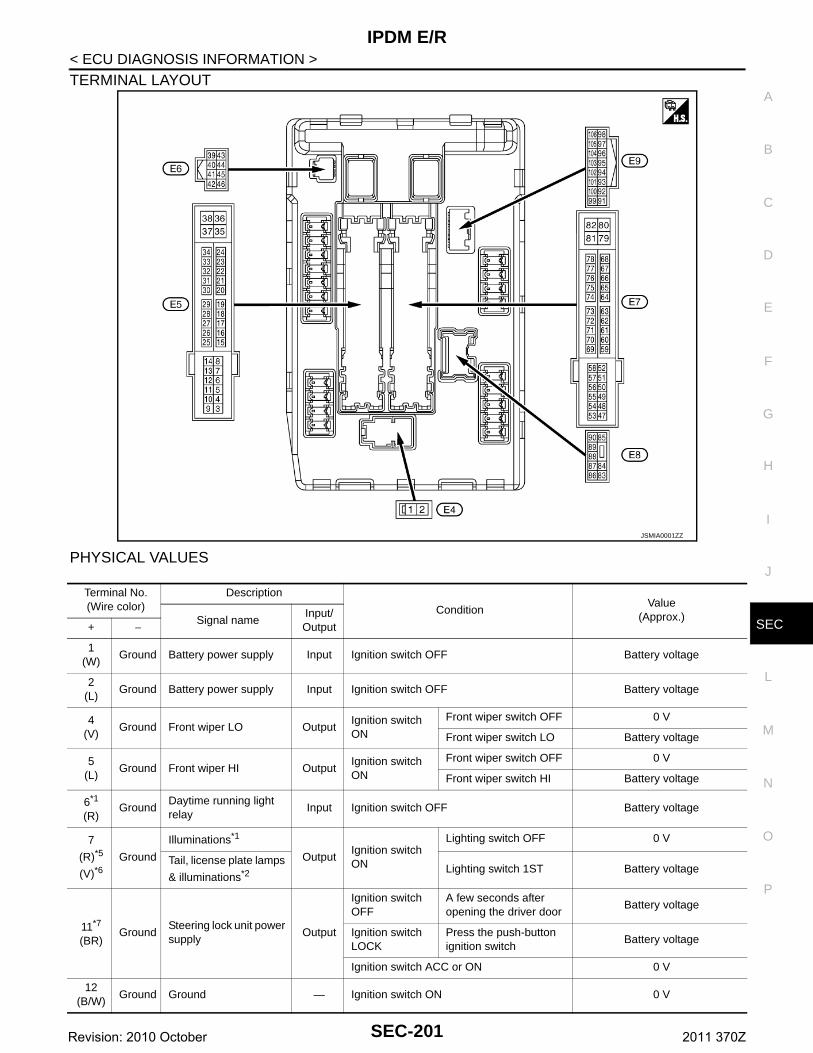
IPDM E/R
C
D
E
F
G
H
I
J
L
M
A
B
EC
N
O
P
< ECU DIAGNOSIS INFORMATION >
S
TERMINAL LAYOUT
PHYSICAL VALUES
JSMIA0001ZZ
Terminal No.(Wire color)
Description
ConditionValue
(Approx.)Signal nameInput/ Output+ −
1(W)
Ground Battery power supply Input Ignition switch OFF Battery voltage
2(L)
Ground Battery power supply Input Ignition switch OFF Battery voltage
4(V)
Ground Front wiper LO OutputIgnition switch ON
Front wiper switch OFF 0 V
Front wiper switch LO Battery voltage
5(L)
Ground Front wiper HI OutputIgnition switch ON
Front wiper switch OFF 0 V
Front wiper switch HI Battery voltage
6*1
(R)Ground
Daytime running light relay
Input Ignition switch OFF Battery voltage
7
(R)*5
(V)*6Ground
Illuminations*1
OutputIgnition switch ON
Lighting switch OFF 0 V
Tail, license plate lamps
& illuminations*2 Lighting switch 1ST Battery voltage
11*7
(BR)Ground
Steering lock unit power supply
Output
Ignition switch OFF
A few seconds after opening the driver door
Battery voltage
Ignition switch LOCK
Press the push-button ignition switch
Battery voltage
Ignition switch ACC or ON 0 V
12(B/W)
Ground Ground — Ignition switch ON 0 V
SEC-201Revision: 2010 October 2011 370Z
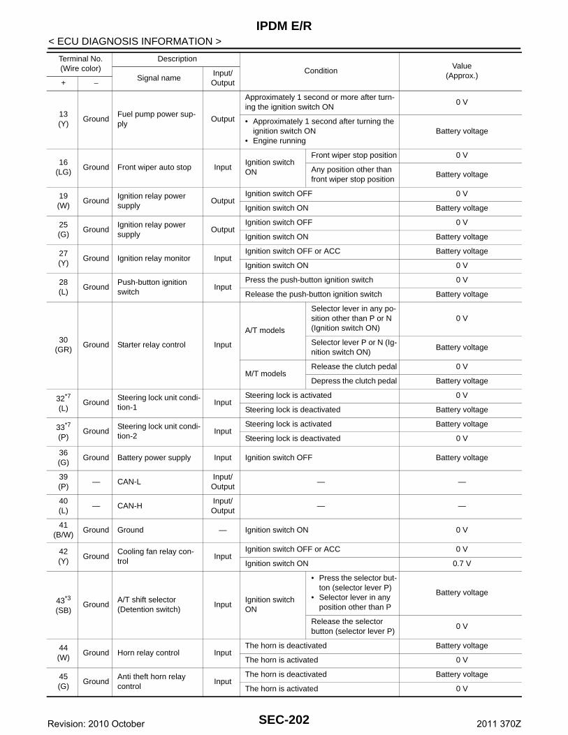
IPDM E/R
< ECU DIAGNOSIS INFORMATION >13(Y)
GroundFuel pump power sup-ply
Output
Approximately 1 second or more after turn-ing the ignition switch ON
0 V
• Approximately 1 second after turning the ignition switch ON
• Engine runningBattery voltage
16(LG)
Ground Front wiper auto stop InputIgnition switch ON
Front wiper stop position 0 V
Any position other than front wiper stop position
Battery voltage
19(W)
GroundIgnition relay power supply
OutputIgnition switch OFF 0 V
Ignition switch ON Battery voltage
25(G)
GroundIgnition relay power supply
OutputIgnition switch OFF 0 V
Ignition switch ON Battery voltage
27(Y)
Ground Ignition relay monitor InputIgnition switch OFF or ACC Battery voltage
Ignition switch ON 0 V
28(L)
GroundPush-button ignition switch
InputPress the push-button ignition switch 0 V
Release the push-button ignition switch Battery voltage
30(GR)
Ground Starter relay control Input
A/T models
Selector lever in any po-sition other than P or N (Ignition switch ON)
0 V
Selector lever P or N (Ig-nition switch ON)
Battery voltage
M/T modelsRelease the clutch pedal 0 V
Depress the clutch pedal Battery voltage
32*7
(L)Ground
Steering lock unit condi-tion-1
InputSteering lock is activated 0 V
Steering lock is deactivated Battery voltage
33*7
(P)Ground
Steering lock unit condi-tion-2
InputSteering lock is activated Battery voltage
Steering lock is deactivated 0 V
36(G)
Ground Battery power supply Input Ignition switch OFF Battery voltage
39(P)
— CAN-LInput/ Output
— —
40(L)
— CAN-HInput/ Output
— —
41(B/W)
Ground Ground — Ignition switch ON 0 V
42(Y)
GroundCooling fan relay con-trol
InputIgnition switch OFF or ACC 0 V
Ignition switch ON 0.7 V
43*3
(SB)Ground
A/T shift selector(Detention switch)
InputIgnition switch ON
• Press the selector but-ton (selector lever P)
• Selector lever in any position other than P
Battery voltage
Release the selector button (selector lever P)
0 V
44(W)
Ground Horn relay control InputThe horn is deactivated Battery voltage
The horn is activated 0 V
45(G)
GroundAnti theft horn relay control
InputThe horn is deactivated Battery voltage
The horn is activated 0 V
Terminal No.(Wire color)
Description
ConditionValue
(Approx.)Signal nameInput/ Output+ −
SEC-202Revision: 2010 October 2011 370Z
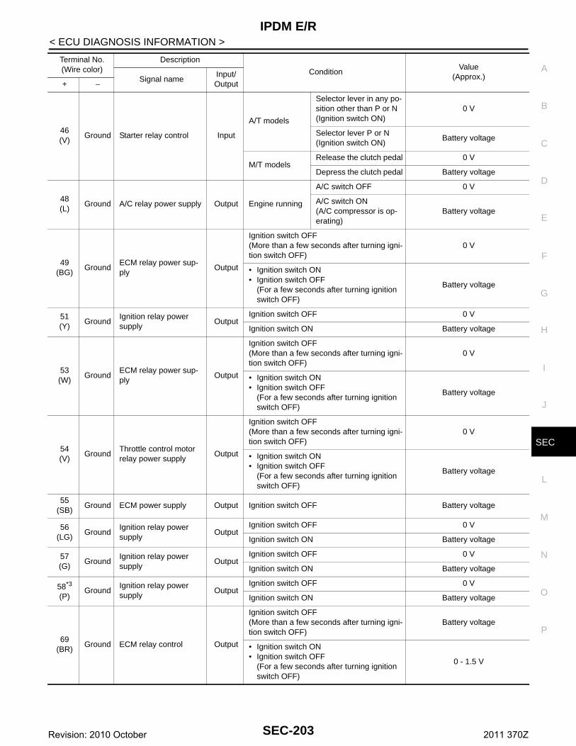
IPDM E/R
C
D
E
F
G
H
I
J
L
M
A
B
EC
N
O
P
< ECU DIAGNOSIS INFORMATION >
S
46(V)
Ground Starter relay control Input
A/T models
Selector lever in any po-sition other than P or N (Ignition switch ON)
0 V
Selector lever P or N(Ignition switch ON)
Battery voltage
M/T modelsRelease the clutch pedal 0 V
Depress the clutch pedal Battery voltage
48(L)
Ground A/C relay power supply Output Engine running
A/C switch OFF 0 V
A/C switch ON(A/C compressor is op-erating)
Battery voltage
49(BG)
GroundECM relay power sup-ply
Output
Ignition switch OFF(More than a few seconds after turning igni-tion switch OFF)
0 V
• Ignition switch ON• Ignition switch OFF
(For a few seconds after turning ignition switch OFF)
Battery voltage
51(Y)
GroundIgnition relay power supply
OutputIgnition switch OFF 0 V
Ignition switch ON Battery voltage
53(W)
GroundECM relay power sup-ply
Output
Ignition switch OFF(More than a few seconds after turning igni-tion switch OFF)
0 V
• Ignition switch ON• Ignition switch OFF
(For a few seconds after turning ignition switch OFF)
Battery voltage
54(V)
GroundThrottle control motor relay power supply
Output
Ignition switch OFF(More than a few seconds after turning igni-tion switch OFF)
0 V
• Ignition switch ON• Ignition switch OFF
(For a few seconds after turning ignition switch OFF)
Battery voltage
55(SB)
Ground ECM power supply Output Ignition switch OFF Battery voltage
56(LG)
GroundIgnition relay power supply
OutputIgnition switch OFF 0 V
Ignition switch ON Battery voltage
57(G)
GroundIgnition relay power supply
OutputIgnition switch OFF 0 V
Ignition switch ON Battery voltage
58*3
(P)Ground
Ignition relay power supply
OutputIgnition switch OFF 0 V
Ignition switch ON Battery voltage
69(BR)
Ground ECM relay control Output
Ignition switch OFF(More than a few seconds after turning igni-tion switch OFF)
Battery voltage
• Ignition switch ON• Ignition switch OFF
(For a few seconds after turning ignition switch OFF)
0 - 1.5 V
Terminal No.(Wire color)
Description
ConditionValue
(Approx.)Signal nameInput/ Output+ −
SEC-203Revision: 2010 October 2011 370Z
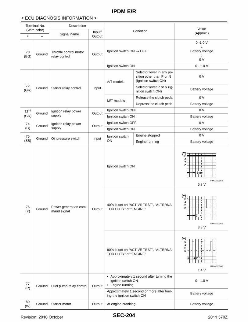
IPDM E/R
< ECU DIAGNOSIS INFORMATION >70(BG)
GroundThrottle control motor relay control
OutputIgnition switch ON → OFF
0 -1.0 V ↓
Battery voltage↓
0 V
Ignition switch ON 0 - 1.0 V
72(GR)
Ground Starter relay control Input
A/T models
Selector lever in any po-sition other than P or N (Ignition switch ON)
0 V
Selector lever P or N (Ig-nition switch ON)
Battery voltage
M/T modelsRelease the clutch pedal 0 V
Depress the clutch pedal Battery voltage
73*4
(GR)Ground
Ignition relay power supply
OutputIgnition switch OFF 0 V
Ignition switch ON Battery voltage
74(G)
GroundIgnition relay power supply
OutputIgnition switch OFF 0 V
Ignition switch ON Battery voltage
75(SB)
Ground Oil pressure switch InputIgnition switch ON
Engine stopped 0 V
Engine running Battery voltage
76(Y)
GroundPower generation com-mand signal
Output
Ignition switch ON
6.3 V
40% is set on “ACTIVE TEST”, “ALTERNA-TOR DUTY” of “ENGINE”
3.8 V
80% is set on “ACTIVE TEST”, “ALTERNA-TOR DUTY” of “ENGINE”
1.4 V
77(R)
Ground Fuel pump relay control Output
• Approximately 1 second after turning the ignition switch ON
• Engine running0 - 1.0 V
Approximately 1 second or more after turn-ing the ignition switch ON
Battery voltage
80(W)
Ground Starter motor Output At engine cranking Battery voltage
Terminal No.(Wire color)
Description
ConditionValue
(Approx.)Signal nameInput/ Output+ −
JPMIA0001GB
JPMIA0002GB
JPMIA0003GB
SEC-204Revision: 2010 October 2011 370Z
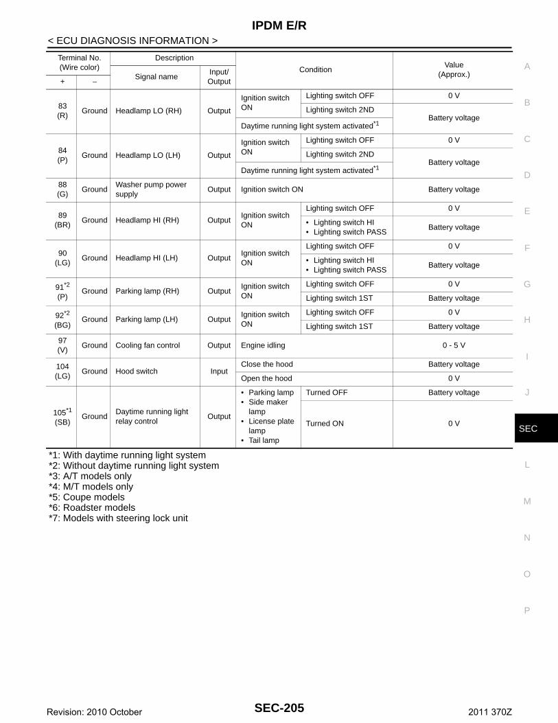
IPDM E/R
C
D
E
F
G
H
I
J
L
M
A
B
EC
N
O
P
< ECU DIAGNOSIS INFORMATION >
S
*1: With daytime running light system*2: Without daytime running light system*3: A/T models only*4: M/T models only*5: Coupe models*6: Roadster models*7: Models with steering lock unit
83(R)
Ground Headlamp LO (RH) Output
Ignition switch ON
Lighting switch OFF 0 V
Lighting switch 2NDBattery voltage
Daytime running light system activated*1
84(P)
Ground Headlamp LO (LH) Output
Ignition switch ON
Lighting switch OFF 0 V
Lighting switch 2NDBattery voltage
Daytime running light system activated*1
88(G)
GroundWasher pump power supply
Output Ignition switch ON Battery voltage
89(BR)
Ground Headlamp HI (RH) OutputIgnition switch ON
Lighting switch OFF 0 V
• Lighting switch HI• Lighting switch PASS
Battery voltage
90(LG)
Ground Headlamp HI (LH) OutputIgnition switch ON
Lighting switch OFF 0 V
• Lighting switch HI• Lighting switch PASS
Battery voltage
91*2
(P)Ground Parking lamp (RH) Output
Ignition switch ON
Lighting switch OFF 0 V
Lighting switch 1ST Battery voltage
92*2
(BG)Ground Parking lamp (LH) Output
Ignition switch ON
Lighting switch OFF 0 V
Lighting switch 1ST Battery voltage
97(V)
Ground Cooling fan control Output Engine idling 0 - 5 V
104(LG)
Ground Hood switch InputClose the hood Battery voltage
Open the hood 0 V
105*1
(SB)Ground
Daytime running light relay control
Output
• Parking lamp• Side maker
lamp• License plate
lamp• Tail lamp
Turned OFF Battery voltage
Turned ON 0 V
Terminal No.(Wire color)
Description
ConditionValue
(Approx.)Signal nameInput/ Output+ −
SEC-205Revision: 2010 October 2011 370Z
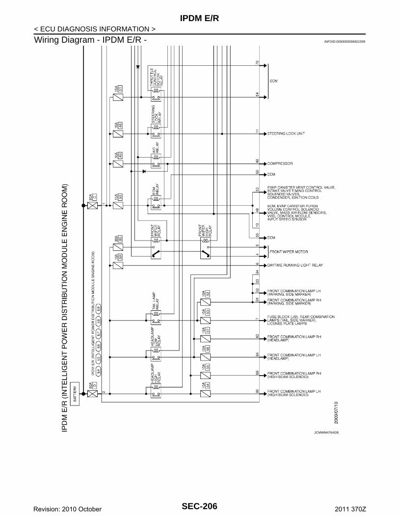
IPDM E/R
< ECU DIAGNOSIS INFORMATION >Wiring Diagram - IPDM E/R - INFOID:0000000006921599
JCMWM4764GB
SEC-206Revision: 2010 October 2011 370Z
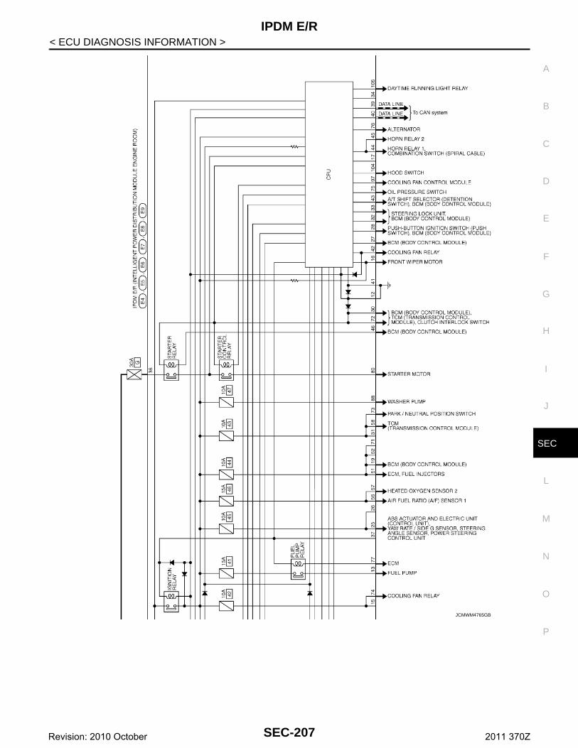
IPDM E/R
C
D
E
F
G
H
I
J
L
M
A
B
EC
N
O
P
< ECU DIAGNOSIS INFORMATION >
S
JCMWM4765GB
SEC-207Revision: 2010 October 2011 370Z
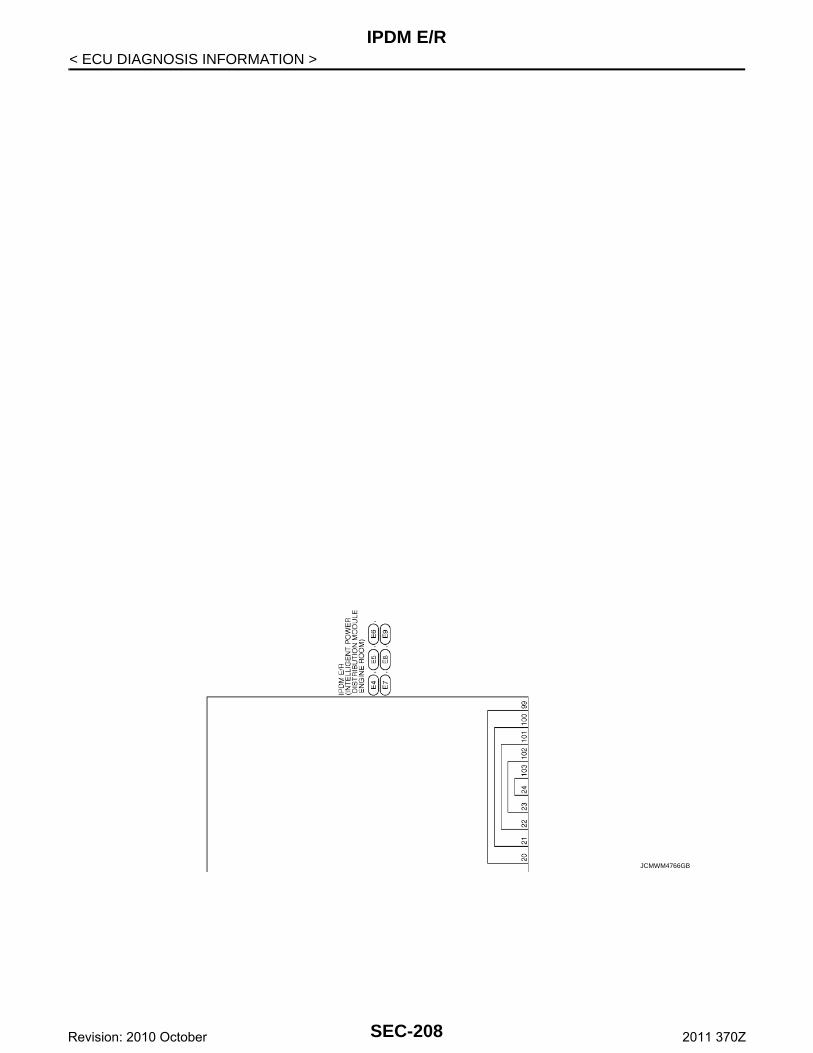
IPDM E/R
< ECU DIAGNOSIS INFORMATION >JCMWM4766GB
SEC-208Revision: 2010 October 2011 370Z
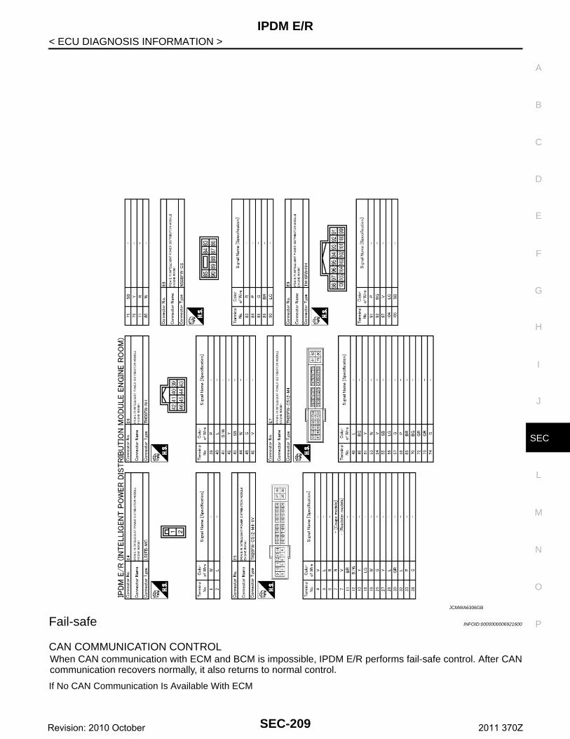
IPDM E/R
C
D
E
F
G
H
I
J
L
M
A
B
EC
N
O
P
< ECU DIAGNOSIS INFORMATION >
S
Fail-safe INFOID:0000000006921600
CAN COMMUNICATION CONTROLWhen CAN communication with ECM and BCM is impossible, IPDM E/R performs fail-safe control. After CANcommunication recovers normally, it also returns to normal control.
If No CAN Communication Is Available With ECM
JCMWA6306GB
SEC-209Revision: 2010 October 2011 370Z
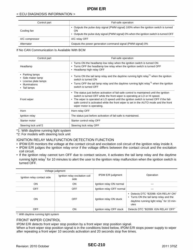
IPDM E/R
< ECU DIAGNOSIS INFORMATION >If No CAN Communication Is Available With BCM
*1: With daytime running light system*2: For models with steering lock unit
IGNITION RELAY MALFUNCTION DETECTION FUNCTION• IPDM E/R monitors the voltage at the contact circuit and excitation coil circuit of the ignition relay inside it. • IPDM E/R judges the ignition relay error if the voltage differs between the contact circuit and the excitation
coil circuit.• If the ignition relay cannot turn OFF due to contact seizure, it activates the tail lamp relay and the daytime
running light relay* for 10 minutes to alert the user to the ignition relay malfunction when the ignition switch isturned OFF.
*: With daytime running light system
FRONT WIPER CONTROLIPDM E/R detects front wiper stop position by a front wiper stop position signal.When a front wiper stop position signal is in the conditions listed below, IPDM E/R stops power supply to wiperafter repeating a front wiper 10 seconds activation and 20 seconds stop five times.
Control part Fail-safe operation
Cooling fan• Outputs the pulse duty signal (PWM signal) 100% when the ignition switch is turned
ON• Outputs the pulse duty signal (PWM signal) 0% when the ignition switch is turned OFF
A/C compressor A/C relay OFF
Alternator Outputs the power generation command signal (PWM signal) 0%
Control part Fail-safe operation
Headlamp• Turns ON the headlamp low relay when the ignition switch is turned ON• Turns OFF the headlamp low relay when the ignition switch is turned OFF• Headlamp high relay OFF
• Parking lamps• Side maker lamp• License plate lamps• Illuminations• Tail lamps
• Turns ON the tail lamp relay and the daytime running light relay*1 when the ignition switch is turned ON
• Turns OFF the tail lamp relay and the daytime running light relay*1 when the ignition switch is turned OFF
Front wiper
• The status just before activation of fail-safe control is maintained until the ignition switch is turned OFF while the front wiper is operating at LO or HI speed.
• The wiper is operated at LO speed until the ignition switch is turned OFF if the fail-safe control is activated while the front wiper is set in the AUTO mode and the front wiper motor is operating.
Horn Horn relay OFF
Ignition relay The status just before activation of fail-safe is maintained.
Starter motor Starter control relay OFF
Steering lock unit*2 Steering lock relay OFF
Voltage judgment
IPDM E/R judgment OperationIgnition relay contact side
Ignition relay excitation coil side
ON ON Ignition relay ON normal —
OFF OFF Ignition relay OFF normal —
ON OFF Ignition relay ON stuck
• Detects DTC “B2098: IGN RELAY ON”• Turns ON the tail lamp relay and the
daytime running light relay* for 10 min-utes
OFF ON Ignition relay OFF stuck Detects DTC “B2099: IGN RELAY OFF”
SEC-210Revision: 2010 October 2011 370Z
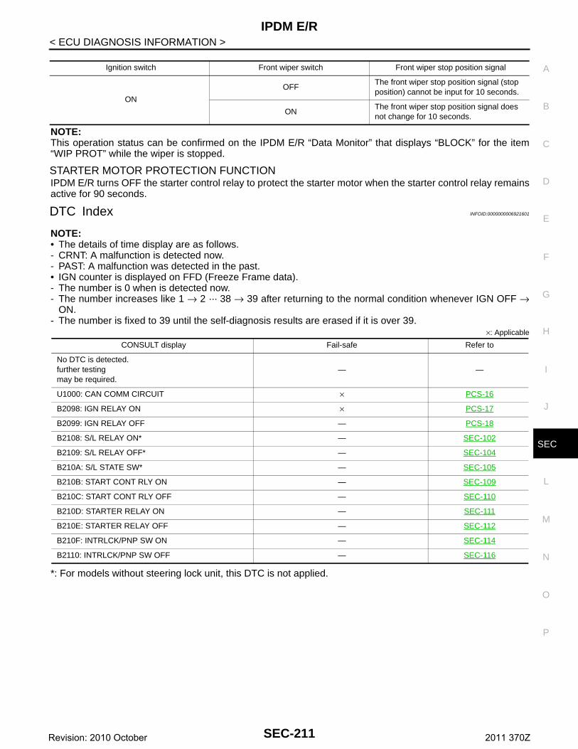
IPDM E/R
C
D
E
F
G
H
I
J
L
M
A
B
EC
N
O
P
< ECU DIAGNOSIS INFORMATION >
S
NOTE:This operation status can be confirmed on the IPDM E/R “Data Monitor” that displays “BLOCK” for the item“WIP PROT” while the wiper is stopped.
STARTER MOTOR PROTECTION FUNCTIONIPDM E/R turns OFF the starter control relay to protect the starter motor when the starter control relay remainsactive for 90 seconds.
DTC Index INFOID:0000000006921601
NOTE:• The details of time display are as follows.- CRNT: A malfunction is detected now.- PAST: A malfunction was detected in the past.• IGN counter is displayed on FFD (Freeze Frame data).- The number is 0 when is detected now.- The number increases like 1 → 2 ··· 38 → 39 after returning to the normal condition whenever IGN OFF →
ON.- The number is fixed to 39 until the self-diagnosis results are erased if it is over 39.
×: Applicable
*: For models without steering lock unit, this DTC is not applied.
Ignition switch Front wiper switch Front wiper stop position signal
ON
OFFThe front wiper stop position signal (stop position) cannot be input for 10 seconds.
ONThe front wiper stop position signal does not change for 10 seconds.
CONSULT display Fail-safe Refer to
No DTC is detected.further testingmay be required.
— —
U1000: CAN COMM CIRCUIT × PCS-16
B2098: IGN RELAY ON × PCS-17
B2099: IGN RELAY OFF — PCS-18
B2108: S/L RELAY ON* — SEC-102
B2109: S/L RELAY OFF* — SEC-104
B210A: S/L STATE SW* — SEC-105
B210B: START CONT RLY ON — SEC-109
B210C: START CONT RLY OFF — SEC-110
B210D: STARTER RELAY ON — SEC-111
B210E: STARTER RELAY OFF — SEC-112
B210F: INTRLCK/PNP SW ON — SEC-114
B2110: INTRLCK/PNP SW OFF — SEC-116
SEC-211Revision: 2010 October 2011 370Z
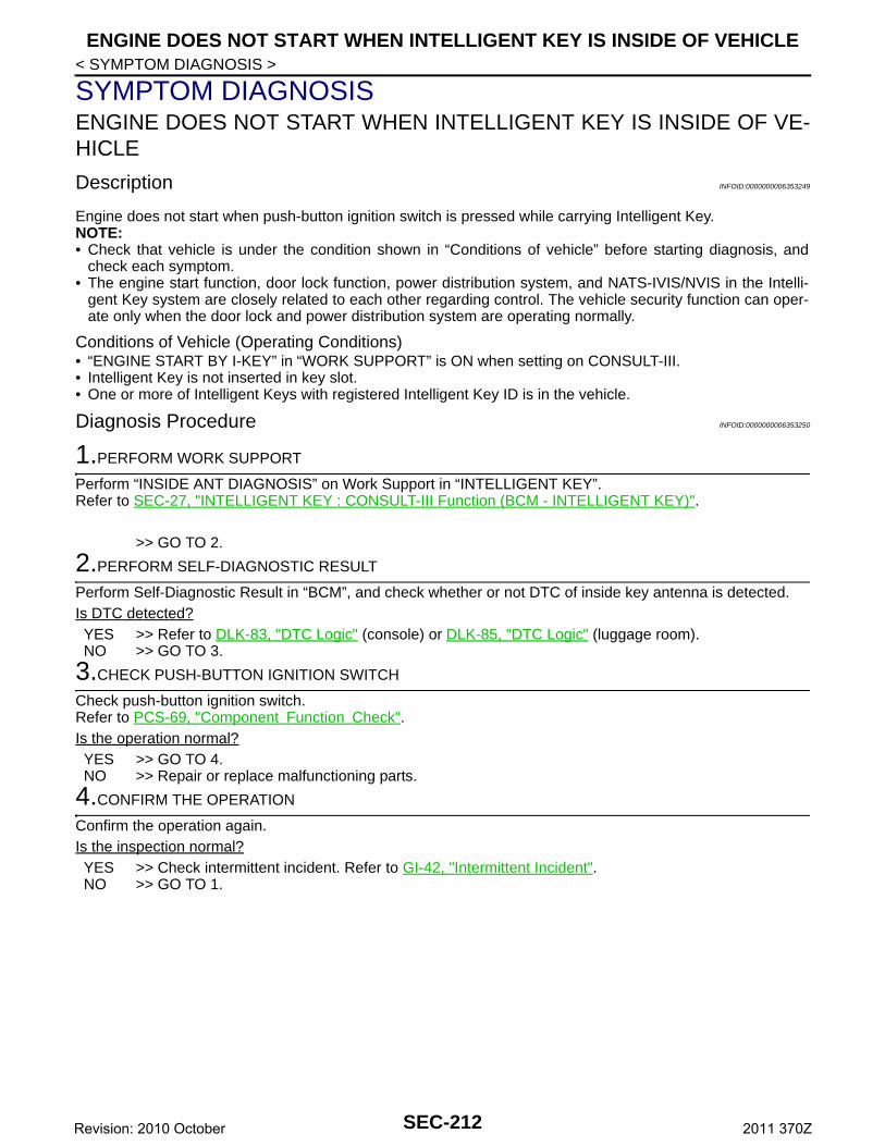
ENGINE DOES NOT START WHEN INTELLIGENT KEY IS INSIDE OF VEHICLE
< SYMPTOM DIAGNOSIS >SYMPTOM DIAGNOSISENGINE DOES NOT START WHEN INTELLIGENT KEY IS INSIDE OF VE-HICLE
Description INFOID:0000000006353249
Engine does not start when push-button ignition switch is pressed while carrying Intelligent Key.NOTE:• Check that vehicle is under the condition shown in “Conditions of vehicle” before starting diagnosis, and
check each symptom.• The engine start function, door lock function, power distribution system, and NATS-IVIS/NVIS in the Intelli-
gent Key system are closely related to each other regarding control. The vehicle security function can oper-ate only when the door lock and power distribution system are operating normally.
Conditions of Vehicle (Operating Conditions)• “ENGINE START BY I-KEY” in “WORK SUPPORT” is ON when setting on CONSULT-III.• Intelligent Key is not inserted in key slot.• One or more of Intelligent Keys with registered Intelligent Key ID is in the vehicle.
Diagnosis Procedure INFOID:0000000006353250
1.PERFORM WORK SUPPORT
Perform “INSIDE ANT DIAGNOSIS” on Work Support in “INTELLIGENT KEY”.Refer to SEC-27, "INTELLIGENT KEY : CONSULT-III Function (BCM - INTELLIGENT KEY)".
>> GO TO 2.
2.PERFORM SELF-DIAGNOSTIC RESULT
Perform Self-Diagnostic Result in “BCM”, and check whether or not DTC of inside key antenna is detected.Is DTC detected?YES >> Refer to DLK-83, "DTC Logic" (console) or DLK-85, "DTC Logic" (luggage room).NO >> GO TO 3.
3.CHECK PUSH-BUTTON IGNITION SWITCH
Check push-button ignition switch.Refer to PCS-69, "Component Function Check".Is the operation normal?YES >> GO TO 4.NO >> Repair or replace malfunctioning parts.
4.CONFIRM THE OPERATION
Confirm the operation again.Is the inspection normal?YES >> Check intermittent incident. Refer to GI-42, "Intermittent Incident".NO >> GO TO 1.
SEC-212Revision: 2010 October 2011 370Z
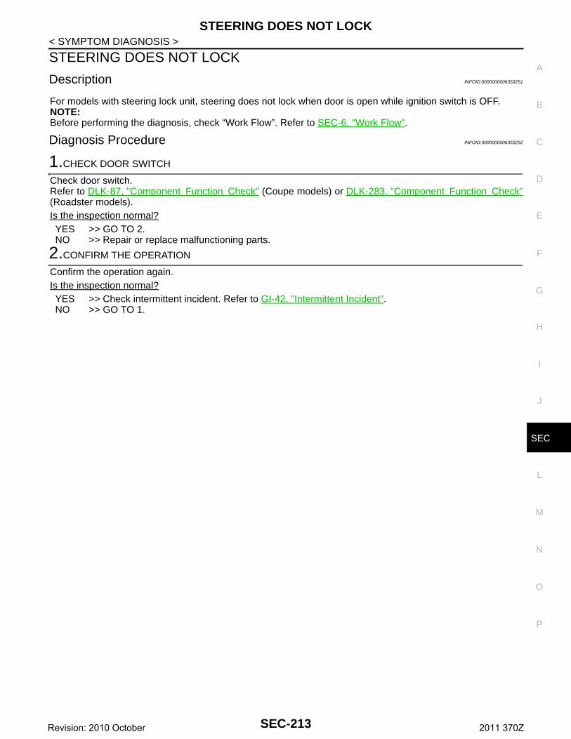
STEERING DOES NOT LOCK
C
D
E
F
G
H
I
J
L
M
A
B
EC
N
O
P
< SYMPTOM DIAGNOSIS >
S
STEERING DOES NOT LOCK
Description INFOID:0000000006353251
For models with steering lock unit, steering does not lock when door is open while ignition switch is OFF.NOTE:Before performing the diagnosis, check “Work Flow”. Refer to SEC-6, "Work Flow".
Diagnosis Procedure INFOID:0000000006353252
1.CHECK DOOR SWITCH
Check door switch.Refer to DLK-87, "Component Function Check" (Coupe models) or DLK-283, "Component Function Check"(Roadster models).Is the inspection normal?YES >> GO TO 2.NO >> Repair or replace malfunctioning parts.
2.CONFIRM THE OPERATION
Confirm the operation again.Is the inspection normal?YES >> Check intermittent incident. Refer to GI-42, "Intermittent Incident".NO >> GO TO 1.
SEC-213Revision: 2010 October 2011 370Z
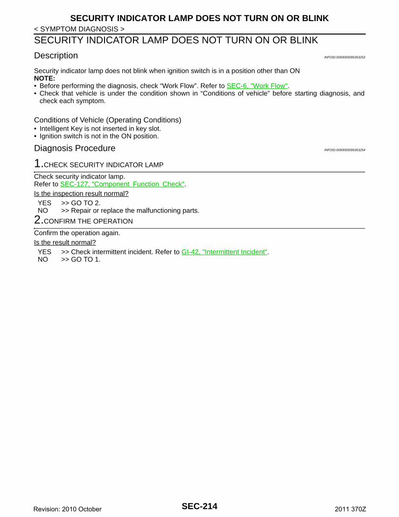
SECURITY INDICATOR LAMP DOES NOT TURN ON OR BLINK
< SYMPTOM DIAGNOSIS >SECURITY INDICATOR LAMP DOES NOT TURN ON OR BLINK
Description INFOID:0000000006353253
Security indicator lamp does not blink when ignition switch is in a position other than ONNOTE:• Before performing the diagnosis, check “Work Flow”. Refer to SEC-6, "Work Flow".• Check that vehicle is under the condition shown in “Conditions of vehicle” before starting diagnosis, and
check each symptom.
Conditions of Vehicle (Operating Conditions)• Intelligent Key is not inserted in key slot.• Ignition switch is not in the ON position.
Diagnosis Procedure INFOID:0000000006353254
1.CHECK SECURITY INDICATOR LAMP
Check security indicator lamp.Refer to SEC-127, "Component Function Check".Is the inspection result normal?YES >> GO TO 2.NO >> Repair or replace the malfunctioning parts.
2.CONFIRM THE OPERATION
Confirm the operation again.Is the result normal?YES >> Check intermittent incident. Refer to GI-42, "Intermittent Incident".NO >> GO TO 1.
SEC-214Revision: 2010 October 2011 370Z
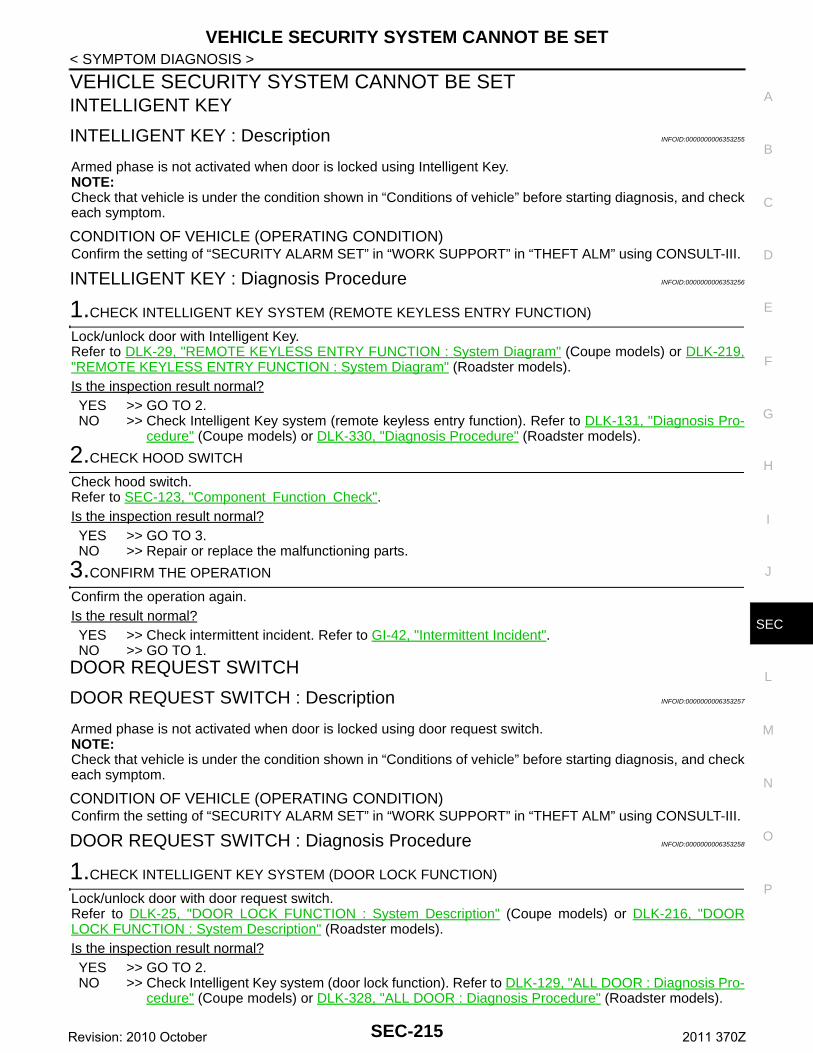
VEHICLE SECURITY SYSTEM CANNOT BE SET
C
D
E
F
G
H
I
J
L
M
A
B
EC
N
O
P
< SYMPTOM DIAGNOSIS >
S
VEHICLE SECURITY SYSTEM CANNOT BE SETINTELLIGENT KEY
INTELLIGENT KEY : Description INFOID:0000000006353255
Armed phase is not activated when door is locked using Intelligent Key.NOTE:Check that vehicle is under the condition shown in “Conditions of vehicle” before starting diagnosis, and checkeach symptom.
CONDITION OF VEHICLE (OPERATING CONDITION)Confirm the setting of “SECURITY ALARM SET” in “WORK SUPPORT” in “THEFT ALM” using CONSULT-III.
INTELLIGENT KEY : Diagnosis Procedure INFOID:0000000006353256
1.CHECK INTELLIGENT KEY SYSTEM (REMOTE KEYLESS ENTRY FUNCTION)
Lock/unlock door with Intelligent Key.Refer to DLK-29, "REMOTE KEYLESS ENTRY FUNCTION : System Diagram" (Coupe models) or DLK-219,"REMOTE KEYLESS ENTRY FUNCTION : System Diagram" (Roadster models).Is the inspection result normal?YES >> GO TO 2.NO >> Check Intelligent Key system (remote keyless entry function). Refer to DLK-131, "Diagnosis Pro-
cedure" (Coupe models) or DLK-330, "Diagnosis Procedure" (Roadster models).
2.CHECK HOOD SWITCH
Check hood switch.Refer to SEC-123, "Component Function Check".Is the inspection result normal?YES >> GO TO 3.NO >> Repair or replace the malfunctioning parts.
3.CONFIRM THE OPERATION
Confirm the operation again.Is the result normal?YES >> Check intermittent incident. Refer to GI-42, "Intermittent Incident".NO >> GO TO 1.
DOOR REQUEST SWITCH
DOOR REQUEST SWITCH : Description INFOID:0000000006353257
Armed phase is not activated when door is locked using door request switch.NOTE:Check that vehicle is under the condition shown in “Conditions of vehicle” before starting diagnosis, and checkeach symptom.
CONDITION OF VEHICLE (OPERATING CONDITION)Confirm the setting of “SECURITY ALARM SET” in “WORK SUPPORT” in “THEFT ALM” using CONSULT-III.
DOOR REQUEST SWITCH : Diagnosis Procedure INFOID:0000000006353258
1.CHECK INTELLIGENT KEY SYSTEM (DOOR LOCK FUNCTION)
Lock/unlock door with door request switch.Refer to DLK-25, "DOOR LOCK FUNCTION : System Description" (Coupe models) or DLK-216, "DOORLOCK FUNCTION : System Description" (Roadster models).Is the inspection result normal?YES >> GO TO 2.NO >> Check Intelligent Key system (door lock function). Refer to DLK-129, "ALL DOOR : Diagnosis Pro-
cedure" (Coupe models) or DLK-328, "ALL DOOR : Diagnosis Procedure" (Roadster models).
SEC-215Revision: 2010 October 2011 370Z
VEHICLE SECURITY SYSTEM CANNOT BE SET
< SYMPTOM DIAGNOSIS >2.CHECK HOOD SWITCH
Check hood switch.Refer to SEC-123, "Component Function Check".Is the inspection result normal?YES >> GO TO 3.NO >> Repair or replace the malfunctioning parts.
3.CONFIRM THE OPERATION
Confirm the operation again.Is the result normal?YES >> Check intermittent incident. Refer to GI-42, "Intermittent Incident".NO >> GO TO 1.
SEC-216Revision: 2010 October 2011 370Z
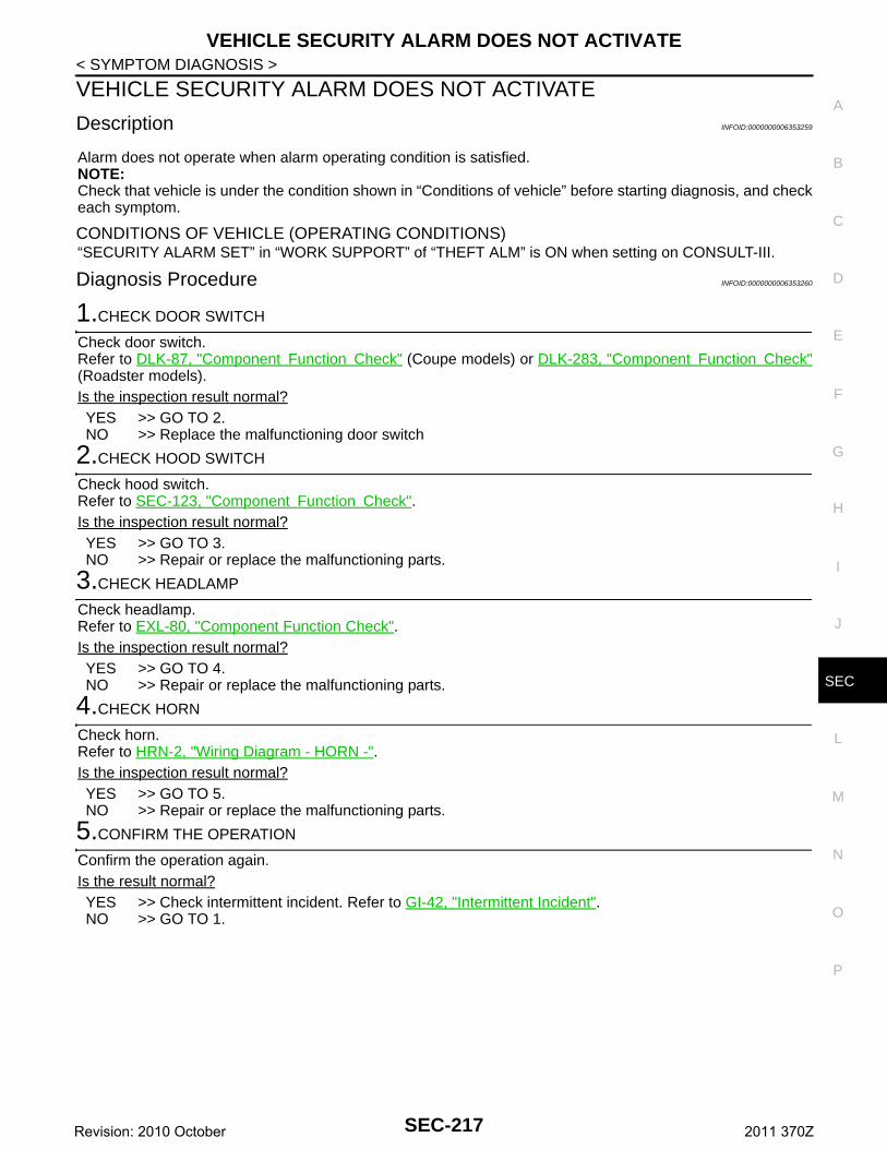
VEHICLE SECURITY ALARM DOES NOT ACTIVATE
C
D
E
F
G
H
I
J
L
M
A
B
EC
N
O
P
< SYMPTOM DIAGNOSIS >
S
VEHICLE SECURITY ALARM DOES NOT ACTIVATE
Description INFOID:0000000006353259
Alarm does not operate when alarm operating condition is satisfied.NOTE:Check that vehicle is under the condition shown in “Conditions of vehicle” before starting diagnosis, and checkeach symptom.
CONDITIONS OF VEHICLE (OPERATING CONDITIONS)“SECURITY ALARM SET” in “WORK SUPPORT” of “THEFT ALM” is ON when setting on CONSULT-III.
Diagnosis Procedure INFOID:0000000006353260
1.CHECK DOOR SWITCH
Check door switch.Refer to DLK-87, "Component Function Check" (Coupe models) or DLK-283, "Component Function Check"(Roadster models).Is the inspection result normal?YES >> GO TO 2.NO >> Replace the malfunctioning door switch
2.CHECK HOOD SWITCH
Check hood switch.Refer to SEC-123, "Component Function Check".Is the inspection result normal?YES >> GO TO 3.NO >> Repair or replace the malfunctioning parts.
3.CHECK HEADLAMP
Check headlamp.Refer to EXL-80, "Component Function Check".Is the inspection result normal?YES >> GO TO 4.NO >> Repair or replace the malfunctioning parts.
4.CHECK HORN
Check horn.Refer to HRN-2, "Wiring Diagram - HORN -".Is the inspection result normal?YES >> GO TO 5.NO >> Repair or replace the malfunctioning parts.
5.CONFIRM THE OPERATION
Confirm the operation again.Is the result normal?YES >> Check intermittent incident. Refer to GI-42, "Intermittent Incident".NO >> GO TO 1.
SEC-217Revision: 2010 October 2011 370Z
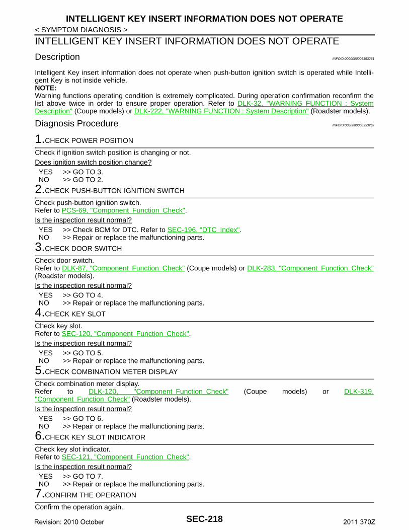
INTELLIGENT KEY INSERT INFORMATION DOES NOT OPERATE
< SYMPTOM DIAGNOSIS >INTELLIGENT KEY INSERT INFORMATION DOES NOT OPERATE
Description INFOID:0000000006353261
Intelligent Key insert information does not operate when push-button ignition switch is operated while Intelli-gent Key is not inside vehicle.NOTE:Warning functions operating condition is extremely complicated. During operation confirmation reconfirm thelist above twice in order to ensure proper operation. Refer to DLK-32, "WARNING FUNCTION : SystemDescription" (Coupe models) or DLK-222, "WARNING FUNCTION : System Description" (Roadster models).
Diagnosis Procedure INFOID:0000000006353262
1.CHECK POWER POSITION
Check if ignition switch position is changing or not.Does ignition switch position change?YES >> GO TO 3.NO >> GO TO 2.
2.CHECK PUSH-BUTTON IGNITION SWITCH
Check push-button ignition switch.Refer to PCS-69, "Component Function Check".Is the inspection result normal?YES >> Check BCM for DTC. Refer to SEC-196, "DTC Index".NO >> Repair or replace the malfunctioning parts.
3.CHECK DOOR SWITCH
Check door switch.Refer to DLK-87, "Component Function Check" (Coupe models) or DLK-283, "Component Function Check"(Roadster models).Is the inspection result normal?YES >> GO TO 4.NO >> Repair or replace the malfunctioning parts.
4.CHECK KEY SLOT
Check key slot.Refer to SEC-120, "Component Function Check".Is the inspection result normal?YES >> GO TO 5.NO >> Repair or replace the malfunctioning parts.
5.CHECK COMBINATION METER DISPLAY
Check combination meter display.Refer to DLK-120, "Component Function Check" (Coupe models) or DLK-319,"Component Function Check" (Roadster models).Is the inspection result normal?YES >> GO TO 6.NO >> Repair or replace the malfunctioning parts.
6.CHECK KEY SLOT INDICATOR
Check key slot indicator.Refer to SEC-121, "Component Function Check".Is the inspection result normal?YES >> GO TO 7.NO >> Repair or replace the malfunctioning parts.
7.CONFIRM THE OPERATION
Confirm the operation again.
SEC-218Revision: 2010 October 2011 370Z
INTELLIGENT KEY INSERT INFORMATION DOES NOT OPERATE
C
D
E
F
G
H
I
J
L
M
A
B
EC
N
O
P
< SYMPTOM DIAGNOSIS >
S
Is the result normal?YES >> Check intermittent incident. Refer to GI-42, "Intermittent Incident".NO >> GO TO 1.
SEC-219Revision: 2010 October 2011 370Z
PANIC ALARM FUNCTION DOES NOT OPERATE
< SYMPTOM DIAGNOSIS >PANIC ALARM FUNCTION DOES NOT OPERATE
Description INFOID:0000000006353263
NOTE:Before performing the diagnosis in the following procedure, check the operation condition. Refer to DLK-29,"REMOTE KEYLESS ENTRY FUNCTION : System Description" (Coupe models) or DLK-220, "REMOTEKEYLESS ENTRY FUNCTION : System Description" (Roadster models).
Diagnosis Procedure INFOID:0000000006353264
1.CHECK REMOTE KEYLESS ENTRY FUNCTION
Check remote keyless entry function.Does door lock/unlock with Intelligent Key button?YES >> GO TO 2.NO >> Refer to DLK-131, "Diagnosis Procedure" (Coupe models) or DLK-330, "Diagnosis Procedure"
(Roadster models).
2.CHECK VEHICLE SECURITY ALARM OPERATION
Check vehicle security alarm operation.Does alarm (headlamp and horn) active?YES >> GO TO 3.NO >> Refer to SEC-217, "Diagnosis Procedure".
3.CHECK “PANIC ALARM SET” SETTING IN “WORK SUPPORT”
Check “PANIC ALARM SET” setting in “WORK SUPPORT”.Refer to SEC-27, "INTELLIGENT KEY : CONSULT-III Function (BCM - INTELLIGENT KEY)".Is the inspection result normal?YES >> GO TO 4.NO >> Set “PANIC ALARM SET” setting in “WORK SUPPORT”.
4.CONFIRM THE OPERATION
Confirm the operation again.Is the result normal?YES >> Check intermittent incident. Refer to GI-42, "Intermittent Incident".NO >> GO TO 1.
SEC-220Revision: 2010 October 2011 370Z
PRECAUTIONS
C
D
E
F
G
H
I
J
L
M
A
B
EC
N
O
P
< PRECAUTION >
S
PRECAUTIONPRECAUTIONSFOR USA AND CANADA
FOR USA AND CANADA : Precaution for Supplemental Restraint System (SRS) "AIR BAG" and "SEAT BELT PRE-TENSIONER" INFOID:0000000006921561
The Supplemental Restraint System such as “AIR BAG” and “SEAT BELT PRE-TENSIONER”, used alongwith a front seat belt, helps to reduce the risk or severity of injury to the driver and front passenger for certaintypes of collision. This system includes seat belt switch inputs and dual stage front air bag modules. The SRSsystem uses the seat belt switches to determine the front air bag deployment, and may only deploy one frontair bag, depending on the severity of a collision and whether the front occupants are belted or unbelted.Information necessary to service the system safely is included in the “SRS AIR BAG” and “SEAT BELT” of thisService Manual.WARNING:• To avoid rendering the SRS inoperative, which could increase the risk of personal injury or death in
the event of a collision that would result in air bag inflation, all maintenance must be performed byan authorized NISSAN/INFINITI dealer.
• Improper maintenance, including incorrect removal and installation of the SRS, can lead to personalinjury caused by unintentional activation of the system. For removal of Spiral Cable and Air BagModule, see “SRS AIR BAG”.
• Never use electrical test equipment on any circuit related to the SRS unless instructed to in this Ser-vice Manual. SRS wiring harnesses can be identified by yellow and/or orange harnesses or harnessconnectors.
PRECAUTIONS WHEN USING POWER TOOLS (AIR OR ELECTRIC) AND HAMMERSWARNING:• When working near the Air Bag Diagnosis Sensor Unit or other Air Bag System sensors with the
ignition ON or engine running, never use air or electric power tools or strike near the sensor(s) witha hammer. Heavy vibration could activate the sensor(s) and deploy the air bag(s), possibly causingserious injury.
• When using air or electric power tools or hammers, always switch the ignition OFF, disconnect thebattery, and wait at least 3 minutes before performing any service.
FOR USA AND CANADA : Precaution Necessary for Steering Wheel Rotation after Battery Disconnect INFOID:0000000006921568
NOTE:• Before removing and installing any control units, first turn the ignition switch to the LOCK position, then dis-
connect both battery cables.• After finishing work, confirm that all control unit connectors are connected properly, then re-connect both
battery cables.• Always use CONSULT to perform self-diagnosis as a part of each function inspection after finishing work. If
a DTC is detected, perform trouble diagnosis according to self-diagnosis results.For vehicle with steering lock unit, if the battery is disconnected or discharged, the steering wheel will lock andcannot be turned.If turning the steering wheel is required with the battery disconnected or discharged, follow the operation pro-cedure below before starting the repair operation.
OPERATION PROCEDURE1. Connect both battery cables.
NOTE:Supply power using jumper cables if battery is discharged.
2. Turn the ignition switch to ACC position.(At this time, the steering lock will be released.)
3. Disconnect both battery cables. The steering lock will remain released with both battery cables discon-nected and the steering wheel can be turned.
4. Perform the necessary repair operation.
SEC-221Revision: 2010 October 2011 370Z
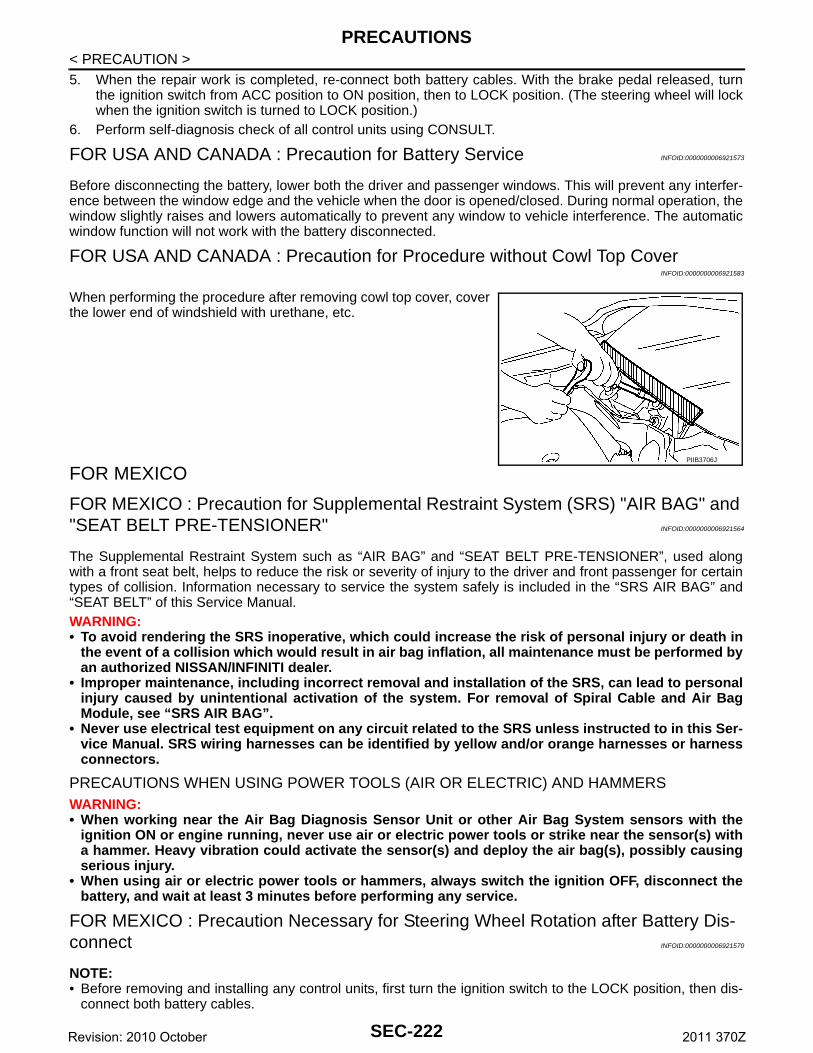
PRECAUTIONS
< PRECAUTION >5. When the repair work is completed, re-connect both battery cables. With the brake pedal released, turnthe ignition switch from ACC position to ON position, then to LOCK position. (The steering wheel will lockwhen the ignition switch is turned to LOCK position.)
6. Perform self-diagnosis check of all control units using CONSULT.
FOR USA AND CANADA : Precaution for Battery Service INFOID:0000000006921573
Before disconnecting the battery, lower both the driver and passenger windows. This will prevent any interfer-ence between the window edge and the vehicle when the door is opened/closed. During normal operation, thewindow slightly raises and lowers automatically to prevent any window to vehicle interference. The automaticwindow function will not work with the battery disconnected.
FOR USA AND CANADA : Precaution for Procedure without Cowl Top CoverINFOID:0000000006921583
When performing the procedure after removing cowl top cover, coverthe lower end of windshield with urethane, etc.
FOR MEXICO
FOR MEXICO : Precaution for Supplemental Restraint System (SRS) "AIR BAG" and "SEAT BELT PRE-TENSIONER" INFOID:0000000006921564
The Supplemental Restraint System such as “AIR BAG” and “SEAT BELT PRE-TENSIONER”, used alongwith a front seat belt, helps to reduce the risk or severity of injury to the driver and front passenger for certaintypes of collision. Information necessary to service the system safely is included in the “SRS AIR BAG” and“SEAT BELT” of this Service Manual.WARNING:• To avoid rendering the SRS inoperative, which could increase the risk of personal injury or death in
the event of a collision which would result in air bag inflation, all maintenance must be performed byan authorized NISSAN/INFINITI dealer.
• Improper maintenance, including incorrect removal and installation of the SRS, can lead to personalinjury caused by unintentional activation of the system. For removal of Spiral Cable and Air BagModule, see “SRS AIR BAG”.
• Never use electrical test equipment on any circuit related to the SRS unless instructed to in this Ser-vice Manual. SRS wiring harnesses can be identified by yellow and/or orange harnesses or harnessconnectors.
PRECAUTIONS WHEN USING POWER TOOLS (AIR OR ELECTRIC) AND HAMMERSWARNING:• When working near the Air Bag Diagnosis Sensor Unit or other Air Bag System sensors with the
ignition ON or engine running, never use air or electric power tools or strike near the sensor(s) witha hammer. Heavy vibration could activate the sensor(s) and deploy the air bag(s), possibly causingserious injury.
• When using air or electric power tools or hammers, always switch the ignition OFF, disconnect thebattery, and wait at least 3 minutes before performing any service.
FOR MEXICO : Precaution Necessary for Steering Wheel Rotation after Battery Dis-connect INFOID:0000000006921570
NOTE:• Before removing and installing any control units, first turn the ignition switch to the LOCK position, then dis-
connect both battery cables.
PIIB3706J
SEC-222Revision: 2010 October 2011 370Z
PRECAUTIONS
C
D
E
F
G
H
I
J
L
M
A
B
EC
N
O
P
< PRECAUTION >
S
• After finishing work, confirm that all control unit connectors are connected properly, then re-connect bothbattery cables.
• Always use CONSULT to perform self-diagnosis as a part of each function inspection after finishing work. Ifa DTC is detected, perform trouble diagnosis according to self-diagnosis results.
For vehicle with steering lock unit, if the battery is disconnected or discharged, the steering wheel will lock andcannot be turned.If turning the steering wheel is required with the battery disconnected or discharged, follow the operation pro-cedure below before starting the repair operation.
OPERATION PROCEDURE1. Connect both battery cables.
NOTE:Supply power using jumper cables if battery is discharged.
2. Turn the ignition switch to ACC position.(At this time, the steering lock will be released.)
3. Disconnect both battery cables. The steering lock will remain released with both battery cables discon-nected and the steering wheel can be turned.
4. Perform the necessary repair operation.5. When the repair work is completed, re-connect both battery cables. With the brake pedal released, turn
the ignition switch from ACC position to ON position, then to LOCK position. (The steering wheel will lockwhen the ignition switch is turned to LOCK position.)
6. Perform self-diagnosis check of all control units using CONSULT.
FOR MEXICO : Precaution for Battery Service INFOID:0000000006921576
Before disconnecting the battery, lower both the driver and passenger windows. This will prevent any interfer-ence between the window edge and the vehicle when the door is opened/closed. During normal operation, thewindow slightly raises and lowers automatically to prevent any window to vehicle interference. The automaticwindow function will not work with the battery disconnected.
FOR MEXICO : Precaution for Procedure without Cowl Top Cover INFOID:0000000006921584
When performing the procedure after removing cowl top cover, coverthe lower end of windshield with urethane, etc.
PIIB3706J
SEC-223Revision: 2010 October 2011 370Z
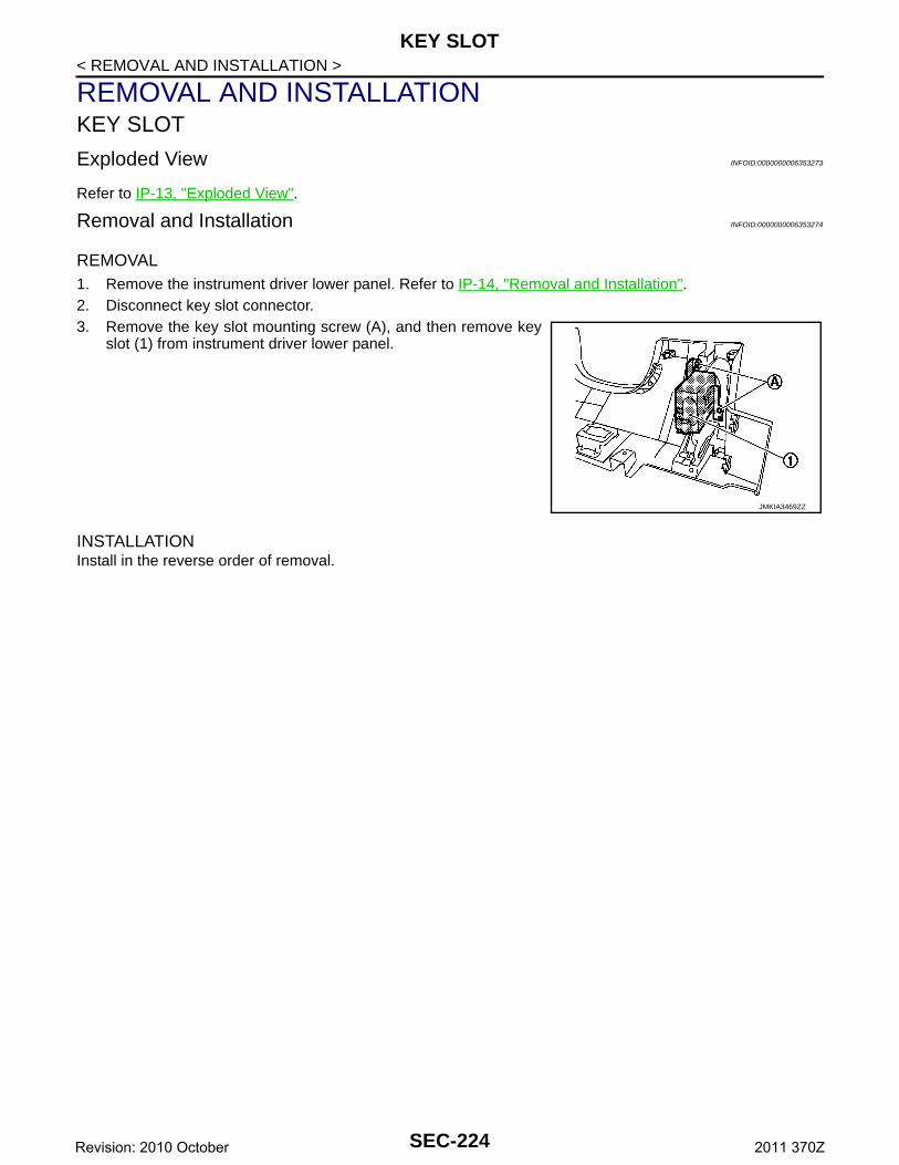
KEY SLOT
< REMOVAL AND INSTALLATION >REMOVAL AND INSTALLATIONKEY SLOT
Exploded View INFOID:0000000006353273
Refer to IP-13, "Exploded View".
Removal and Installation INFOID:0000000006353274
REMOVAL1. Remove the instrument driver lower panel. Refer to IP-14, "Removal and Installation".2. Disconnect key slot connector.3. Remove the key slot mounting screw (A), and then remove key
slot (1) from instrument driver lower panel.
INSTALLATIONInstall in the reverse order of removal.
JMKIA3469ZZ
SEC-224Revision: 2010 October 2011 370Z
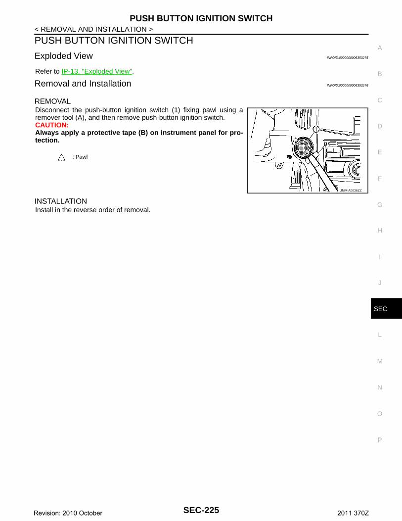
PUSH BUTTON IGNITION SWITCH
C
D
E
F
G
H
I
J
L
M
A
B
EC
N
O
P
< REMOVAL AND INSTALLATION >
S
PUSH BUTTON IGNITION SWITCH
Exploded View INFOID:0000000006353275
Refer to IP-13, "Exploded View".
Removal and Installation INFOID:0000000006353276
REMOVALDisconnect the push-button ignition switch (1) fixing pawl using aremover tool (A), and then remove push-button ignition switch.CAUTION:Always apply a protective tape (B) on instrument panel for pro-tection.
INSTALLATIONInstall in the reverse order of removal.
: Pawl
JMMIA0036ZZ
SEC-225Revision: 2010 October 2011 370Z


