Embed Size (px)
Citation preview
119
Seattle Fire Department
Chapter 4 • Engine Evolutions
ENGINE COMPANY INTRODUCTION
Overview
Engine company hose evolutions will follow a department-wide standard.The goal is to provide the most efficient methods of performing fire ground operations.
All members shall possess a solid understanding of the operations described within this section, as they will serve as the basis for engine company fire ground operations. These evolutions will be used to evaluate Recruit Firefighter’s during drill school and Operations Division member’s throughout their careers.
In some instances, emergency situations may not be satisfactorily resolved by utilizing only these basic evolutions. The company Officer maintains the ability to alter these standard methods when necessary.
It should be noted that the Seattle Fire Department Basic Skills Manual is not a tactics textbook. The knowledge and decision-making skills must be learned and practiced using approved curriculum and methods.
Introduction
Stretching and operating hose lines is the primary function of the enginecompany. All members must realize the importance of the initial line stretched at a structural fire. More lives are saved at fire operations by the proper positioning and operating of hose lines than by all other life-saving techniques available to firefighting forces. The majority of structural fires are controlled and extinguished by this initial line.
The first hose line is placed between the fire and any persons endangered by it. Often this is accomplished by stretching the line via the primary means of egress; usually the main entrance or stairway. The purpose of this line is to:
• Allow occupants to evacuate• Allow members to proceed to the floors above the fire for search• Confine and extinguish the fire
If it is determined there is no life hazard in the building, the first line is positioned between the fire and the most severe exposure. This will likely be an internal exposure (within the fire building) in the case of an offensive fire attack or an adjacent building in the event of a defensive fire attack.
Chapter 4
Engine Evolutions
Chap
ter 4 –
Engin
e Evolu
tions

120
Seattle Fire Department
Chapter 4 • Engine Evolutions
ENGINE COMPANY INTRODUCTION
Overview
Engine company hose evolutions will follow a department-wide standard. The goal is to provide the most efficient methods of performing fire ground operations. All members shall possess a solid understanding of the operations described within this section, as they will serve as the basis for engine company fire ground operations. These evolutions will be used to evaluate Recruit Firefighter’s during drill school and Operations Division member’s throughout their careers. In some instances, emergency situations may not be satisfactorily resolved by utilizing only these basic evolutions. The company Officer maintains the ability to alter these standard methods when necessary.
It should be noted that the Seattle Fire Department Basic Skills Manual is not a tactics textbook. The knowledge and decision-making skills must be learned and practiced using approved curriculum and methods.
Introduction
Stretching and operating hose lines is the primary function of the engine company. All members must realize the importance of the initial line stretched at a structural fire. More lives are saved at fire operations by the proper positioning and operating of hose lines than by all other life-saving techniques available to firefighting forces. The majority of structural fires are controlled and extinguished by this initial line. The first hose line is placed between the fire and any persons endangered by it. Often this is accomplished by stretching the line via the primary means of egress; usually the main entrance or stairway. The purpose of this line is to: • Allow occupants to evacuate • Allow members to proceed to the floors above the fire for search • Confine and extinguish the fire
If it is determined there is no life hazard in the building, the first line is positioned between the fire and the most severe exposure. This will likely be an internal exposure (within the fire building) in the case of an offensive fire attack or an adjacent building in the event of a defensive fire attack.

121
Seattle Fire Department
Chapter 4 • Engine Evolutions
The engine company may be confronted with life-saving operations upon arrival. Life-saving operations are placed ahead of firefighting when sufficient firefighters are not available to do both. Judgment is the key factor when confronted with this situation. The best life-saving measure may be a prompt attack on the fire, which, if allowed to spread, would trap occupants. Immediate rescue attempts by the first arriving engine company without simultaneously stretching and positioning a hose line should be attempted only in extreme situations.
BASIC ENGINE COMPANY OPERATIONS
The specific evolution and the size of attack line to be utilized will depend on the following: • Location of fire • Severity of fire • Type of occupancy • Type of construction
When estimating the length of the attack line, consider the distance from the engine or manifold to the entrance door. In some cases, several lengths of hose may be required to reach the entrance. For upper floor fires, the distance from the entrance door to the stairway must also be considered. This is in addition to the amount of hose required to advance up the stairs (typically one length per two floors for a standard return-type stairway). A minimum of one length of hose should be allocated to the fire floor. Some buildings may require more than one section of hose on the fire floor itself.
PHOTO 4.0
As shown above, one length of hose is required to reach the stairs, one length to reach floor three, and an additional length to reach the fire on the fire floor. The total hose stretch in this case is three lengths, or 300 feet. The distance of the lay must be appropriately estimated before the stretch begins.
Seattle Fire Department
Chapter 4 • Engine Evolutions
ENGINE COMPANY INTRODUCTION
Overview
Engine company hose evolutions will follow a department-wide standard. The goal is to provide the most efficient methods of performing fire ground operations. All members shall possess a solid understanding of the operations described within this section, as they will serve as the basis for engine company fire ground operations. These evolutions will be used to evaluate Recruit Firefighter’s during drill school and Operations Division member’s throughout their careers. In some instances, emergency situations may not be satisfactorily resolved by utilizing only these basic evolutions. The company Officer maintains the ability to alter these standard methods when necessary.
It should be noted that the Seattle Fire Department Basic Skills Manual is not a tactics textbook. The knowledge and decision-making skills must be learned and practiced using approved curriculum and methods.
Introduction
Stretching and operating hose lines is the primary function of the engine company. All members must realize the importance of the initial line stretched at a structural fire. More lives are saved at fire operations by the proper positioning and operating of hose lines than by all other life-saving techniques available to firefighting forces. The majority of structural fires are controlled and extinguished by this initial line. The first hose line is placed between the fire and any persons endangered by it. Often this is accomplished by stretching the line via the primary means of egress; usually the main entrance or stairway. The purpose of this line is to: • Allow occupants to evacuate • Allow members to proceed to the floors above the fire for search • Confine and extinguish the fire
If it is determined there is no life hazard in the building, the first line is positioned between the fire and the most severe exposure. This will likely be an internal exposure (within the fire building) in the case of an offensive fire attack or an adjacent building in the event of a defensive fire attack.

122
Seattle Fire Department
Chapter 4 • Engine Evolutions
To minimize the number of lengths of hose required and to provide rapid hose line positioning, consideration must be given to the following possible options: • Stretching hose up the open well of a stairway • Utilization of standpipe systems • Hoisting a hose line with utility rope or drop bag line via the exterior
of the building • Stretching hose up a fire escape
The charging of the line must be done in a safe area. The firefighter assigned to the nozzle position should never enter the immediate fire area without water. Call for water outside of private dwellings or other small buildings. In large buildings, the line should be charged in the stairwell on the floor below the fire, or in a remote smoke-free location protected from the fire area by fire doors. In the case of an exterior fire, charge the line a safe distance away (a minimum of 30 feet). No matter which evolution the engine Officer chooses to perform, hose lines will not be operated in opposition to each other. Likewise, offensive and defensive attack methods will not be combined. In addition, immediate notification must be given to the incident commander when a situation is discovered that requires the positioning of an additional hose line, or if any line is determined to be ineffective. Injury to firefighters is likely to occur if these rules are not followed.
Company Officer Responsibilities
When arriving first, the engine company Officer may well have more influence on the outcome of a fire operation than any other member on scene. Sound decision-making skills regarding incident strategy and tactics are extremely important. The choices made by this Officer will dictate the mode and method of fire attack. The impact that fire department operations will have on the incident will often be a direct result of these initial actions. The company Officer must continually supervise the operation to ensure the evolution and individual assignments are completed safely and efficiently. The Officer should be alert to direct and/or immediately correct any condition that may affect the safety, speed, or satisfactory completion of the evolution.
Engine Placement
The Officer will decide where to position the engine once the fire location has been determined. This decision must be based on several factors, including overall objectives, water source, fire conditions, and the type of

123
Seattle Fire Department
Chapter 4 • Engine Evolutions
evolution to be performed. Every effort must be made to have the hydrant to engine connection to be within 100 feet. If this cannot be accomplished by the initial engine company, the next engine should position their engine at the hydrant to supply the first engine. The engine Officer must also allow for the placement of the ladder company for optimum use of the aerial ladder. The final positioning of the engine company must not impede the incoming ladder companies from the fire building.
PHOTO 4.01
Orders
The manner in which orders are given and assignments made will set the tone for the entire operation. Orders must be given clearly and concisely so that all members are aware of the evolution to be performed. The specific evolution and where the hose line is to be stretched must be indicated. In addition, the length of the attack line must be specified if longer than what is standard for a particular evolution. Some examples are listed below: • “Preconnect to the basement door.” • “1¾” manifold to the front entrance.” • “2½” manifold, 300 feet, to the delta side exposure.” • “Extended 1¾” attack line to floor two, 400 feet.”
The engine company positioned for proper ladder company access.
Seattle Fire Department
Chapter 4 • Engine Evolutions
ENGINE COMPANY INTRODUCTION
Overview
Engine company hose evolutions will follow a department-wide standard. The goal is to provide the most efficient methods of performing fire ground operations. All members shall possess a solid understanding of the operations described within this section, as they will serve as the basis for engine company fire ground operations. These evolutions will be used to evaluate Recruit Firefighter’s during drill school and Operations Division member’s throughout their careers. In some instances, emergency situations may not be satisfactorily resolved by utilizing only these basic evolutions. The company Officer maintains the ability to alter these standard methods when necessary.
It should be noted that the Seattle Fire Department Basic Skills Manual is not a tactics textbook. The knowledge and decision-making skills must be learned and practiced using approved curriculum and methods.
Introduction
Stretching and operating hose lines is the primary function of the engine company. All members must realize the importance of the initial line stretched at a structural fire. More lives are saved at fire operations by the proper positioning and operating of hose lines than by all other life-saving techniques available to firefighting forces. The majority of structural fires are controlled and extinguished by this initial line. The first hose line is placed between the fire and any persons endangered by it. Often this is accomplished by stretching the line via the primary means of egress; usually the main entrance or stairway. The purpose of this line is to: • Allow occupants to evacuate • Allow members to proceed to the floors above the fire for search • Confine and extinguish the fire
If it is determined there is no life hazard in the building, the first line is positioned between the fire and the most severe exposure. This will likely be an internal exposure (within the fire building) in the case of an offensive fire attack or an adjacent building in the event of a defensive fire attack.
124
Seattle Fire Department
Chapter 4 • Engine Evolutions
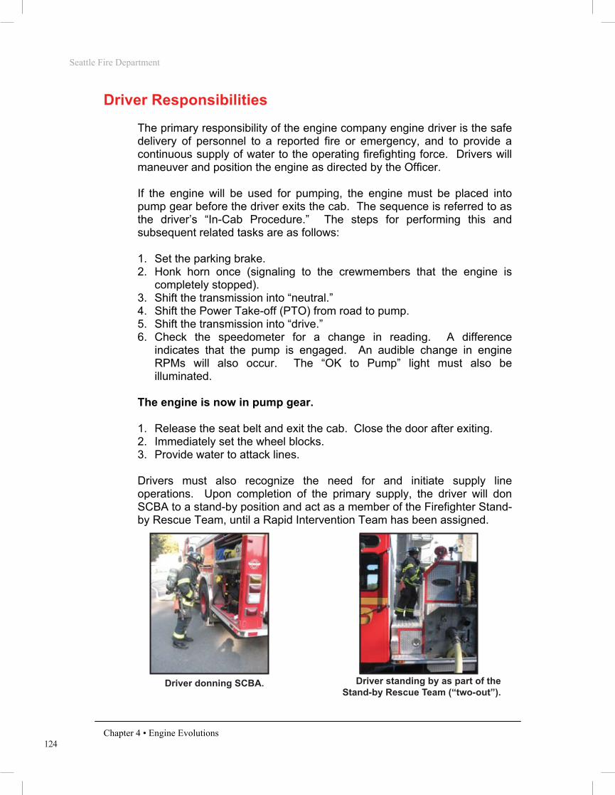
Driver Responsibilities
The primary responsibility of the engine company engine driver is the safe delivery of personnel to a reported fire or emergency, and to provide a continuous supply of water to the operating firefighting force. Drivers will maneuver and position the engine as directed by the Officer. If the engine will be used for pumping, the engine must be placed into pump gear before the driver exits the cab. The sequence is referred to as the driver’s “In-Cab Procedure.” The steps for performing this and subsequent related tasks are as follows: 1. Set the parking brake. 2. Honk horn once (signaling to the crewmembers that the engine is
completely stopped). 3. Shift the transmission into “neutral.” 4. Shift the Power Take-off (PTO) from road to pump. 5. Shift the transmission into “drive.” 6. Check the speedometer for a change in reading. A difference
indicates that the pump is engaged. An audible change in engine RPMs will also occur. The “OK to Pump” light must also be illuminated.
The engine is now in pump gear. 1. Release the seat belt and exit the cab. Close the door after exiting. 2. Immediately set the wheel blocks. 3. Provide water to attack lines. Drivers must also recognize the need for and initiate supply line operations. Upon completion of the primary supply, the driver will don SCBA to a stand-by position and act as a member of the Firefighter Stand-by Rescue Team, until a Rapid Intervention Team has been assigned.
PHOTO 4.1 PHOTO 4.2
Driver donning SCBA. Driver standing by as part of the Stand-by Rescue Team (“two-out”).

125
Seattle Fire Department
Chapter 4 • Engine Evolutions
Position traffic cones to protect personnel, the engine, and hose lines from approaching vehicles. The driver will then obtain a second water supply. Once a second supply has been established, refill any water already used from the engine’s booster tank. Ensure remaining equipment and hose loads are ready for use.
PHOTO 4.3
When not arriving first, the engine company driver must remain aware of water supply needs of the engine companies already on scene.
Firefighter Responsibilities
The position #3 firefighter will be seated on the engine behind the Officer, with the position #4 firefighter seated behind the driver. The member riding in the position #3 seat will act as the nozzle person, while the position #4 firefighter will serve as the back-up person on the hose line with few exceptions. Standard evolutions dictate that each member exiting the rear crew cab will have SCBA donned in the stand-by position. The position #4 firefighter will also be responsible to bring appropriate tools to the fire building. Most often, this tool assignment will be a Halligan married to a HD Flathead axe, hereafter referred to as “the irons.” After forcible entry has been accomplished, the position # 4 firefighter will assist the firefighter assigned to the nozzle in advancing the line to the fire. While advancing, all members must watch carefully for changing conditions and for any victims as you advance into the fire building.
Position traffic cones to increase safety for equipment and operating personnel.
Seattle Fire Department
Chapter 4 • Engine Evolutions
ENGINE COMPANY INTRODUCTION
Overview
Engine company hose evolutions will follow a department-wide standard. The goal is to provide the most efficient methods of performing fire ground operations. All members shall possess a solid understanding of the operations described within this section, as they will serve as the basis for engine company fire ground operations. These evolutions will be used to evaluate Recruit Firefighter’s during drill school and Operations Division member’s throughout their careers. In some instances, emergency situations may not be satisfactorily resolved by utilizing only these basic evolutions. The company Officer maintains the ability to alter these standard methods when necessary.
It should be noted that the Seattle Fire Department Basic Skills Manual is not a tactics textbook. The knowledge and decision-making skills must be learned and practiced using approved curriculum and methods.
Introduction
Stretching and operating hose lines is the primary function of the engine company. All members must realize the importance of the initial line stretched at a structural fire. More lives are saved at fire operations by the proper positioning and operating of hose lines than by all other life-saving techniques available to firefighting forces. The majority of structural fires are controlled and extinguished by this initial line. The first hose line is placed between the fire and any persons endangered by it. Often this is accomplished by stretching the line via the primary means of egress; usually the main entrance or stairway. The purpose of this line is to: • Allow occupants to evacuate • Allow members to proceed to the floors above the fire for search • Confine and extinguish the fire
If it is determined there is no life hazard in the building, the first line is positioned between the fire and the most severe exposure. This will likely be an internal exposure (within the fire building) in the case of an offensive fire attack or an adjacent building in the event of a defensive fire attack.

126
Seattle Fire Department
Chapter 4 • Engine Evolutions
PHOTO 4.4
Once the fire is under control, firefighter’s should begin a primary search of the fire room and attempt to locate windows as they search. Establishing a ventilation opening as soon as possible is a priority. When ventilation has been established and the primary search of the immediate fire area is complete, begin overhaul as necessary to locate any hidden fire. As the above tasks are accomplished (typically by position #4 firefighter and/or the company Officer), it is important to note that the position #3 firefighter will maintain control of the nozzle. In addition, this firefighter does not turn their back on the fire area until overhaul is complete and the fire is declared “tapped.” Until this occurs, the firefighter assigned to the nozzle is providing protection to all other members operating on or above the fire floor. Should a large body of hidden fire be discovered or a flare up occurs, the nozzle firefighter must be in a position to operate the nozzle immediately. If the company Officer is not present inside the fire building, the position #4 firefighter will serve as the “team B” leader. Therefore, it is this member’s responsibility to radio the completion of the tactical benchmarks to the incident commander as appropriate. All members will maintain contact with all others assigned to the team via sight, sound (voice), or touch while operating in a hazardous atmosphere.
Positions #3 and #4 will exit the crew cab with SCBA in the stand-by position.

127
Seattle Fire Department
Chapter 4 • Engine Evolutions
ATTACK LINES
1¾” Preconnect The 1¾” Preconnect evolution will result in the deployment of a 200 foot 1¾” hose bundle that is already connected to the engine. The intention of this lay is to use tank water to initiate the fire attack as quickly as possible.
PHOTO 4.5 PHOTO 4.6
Officer - Direct the driver where to position the engine. Give verbal
directions to the crew designating the evolution to be performed, and the destination of the hose line. Sling the SCBA to the stand-by position as a member of the Firefighter Stand-by Rescue Team or supervise and assist the company in fire suppression and rescue activities as outlined in the POG.
Driver - Position the engine as directed by the company Officer. Perform
the in-cab procedures to place the engine into pump. Exit the cab and place the wheel blocks. Open the tank-to-pump valve and increase engine speed to between 800 -1000 RPMs. Prime the pump until the pressure gauge rises and a full stream of water is flowing out the prime pump discharge. Increase the throttle to bring the discharge pressure between 50-75 PSI. When members on the attack line call for water, slowly open the preconnect discharge valve. Maintain 50-75 PSI while the hose is being filled by manipulating the throttle as needed.
Slot Load Preconnect Crosslay Preconnect
Seattle Fire Department
Chapter 4 • Engine Evolutions
ENGINE COMPANY INTRODUCTION
Overview
Engine company hose evolutions will follow a department-wide standard. The goal is to provide the most efficient methods of performing fire ground operations. All members shall possess a solid understanding of the operations described within this section, as they will serve as the basis for engine company fire ground operations. These evolutions will be used to evaluate Recruit Firefighter’s during drill school and Operations Division member’s throughout their careers. In some instances, emergency situations may not be satisfactorily resolved by utilizing only these basic evolutions. The company Officer maintains the ability to alter these standard methods when necessary.
It should be noted that the Seattle Fire Department Basic Skills Manual is not a tactics textbook. The knowledge and decision-making skills must be learned and practiced using approved curriculum and methods.
Introduction
Stretching and operating hose lines is the primary function of the engine company. All members must realize the importance of the initial line stretched at a structural fire. More lives are saved at fire operations by the proper positioning and operating of hose lines than by all other life-saving techniques available to firefighting forces. The majority of structural fires are controlled and extinguished by this initial line. The first hose line is placed between the fire and any persons endangered by it. Often this is accomplished by stretching the line via the primary means of egress; usually the main entrance or stairway. The purpose of this line is to: • Allow occupants to evacuate • Allow members to proceed to the floors above the fire for search • Confine and extinguish the fire
If it is determined there is no life hazard in the building, the first line is positioned between the fire and the most severe exposure. This will likely be an internal exposure (within the fire building) in the case of an offensive fire attack or an adjacent building in the event of a defensive fire attack.
128
Seattle Fire Department
Chapter 4 • Engine Evolutions
PHOTO 4.7
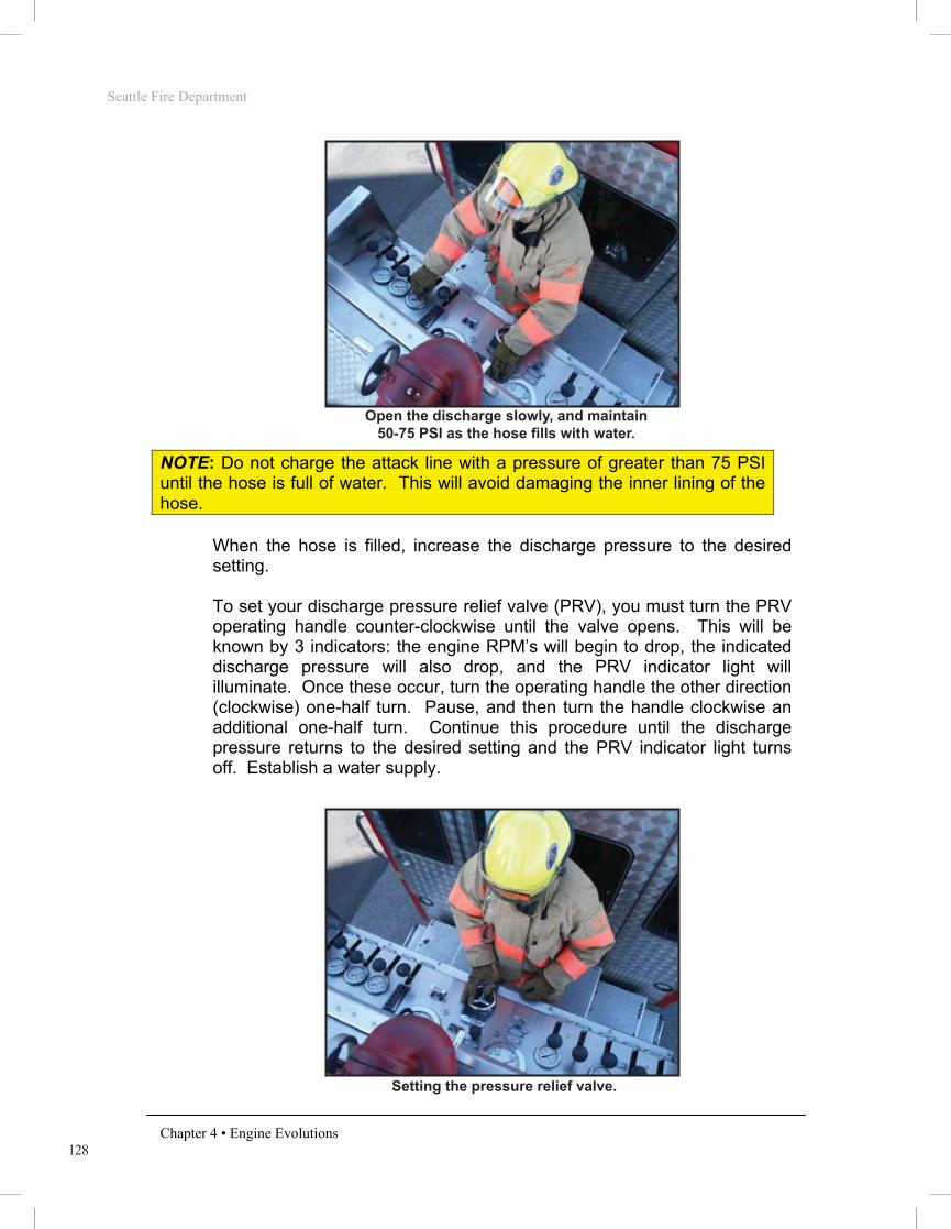
NOTE: Do not charge the attack line with a pressure of greater than 75 PSI until the hose is full of water. This will avoid damaging the inner lining of the hose.
When the hose is filled, increase the discharge pressure to the desired setting. To set your discharge pressure relief valve (PRV), you must turn the PRV operating handle counter-clockwise until the valve opens. This will be known by 3 indicators: the engine RPM’s will begin to drop, the indicated discharge pressure will also drop, and the PRV indicator light will illuminate. Once these occur, turn the operating handle the other direction (clockwise) one-half turn. Pause, and then turn the handle clockwise an additional one-half turn. Continue this procedure until the discharge pressure returns to the desired setting and the PRV indicator light turns off. Establish a water supply.
PHOTO 4.8
Setting the pressure relief valve.
Open the discharge slowly, and maintain 50-75 PSI as the hose fills with water.

129
Seattle Fire Department
Chapter 4 • Engine Evolutions
Position #3 Firefighter - Shoulder-load the 1¾” preconnected hose
load and stretch the line to the location designated by the Officer. Coil or flake the hose, as appropriate, and call for water. Cover with the SCBA. Bleed the air from the charged hose line, assess the fire stream for an appropriate volume of water flow (GPM), and check the fire stream for the appropriate pattern. (AVP)
PHOTO 4.9
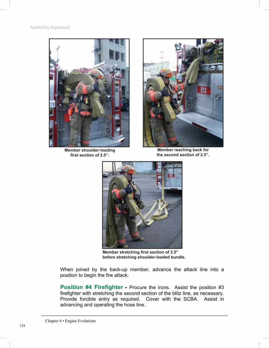
When joined by the back-up member, advance the attack line into a position to begin the fire attack.
Position #4 Firefighter - Procure the irons and meet the position #3
firefighter at the nozzle. Provide forcible entry as required. Cover with the SCBA. Assist in advancing and operating the hose line.
PHOTO 4.10
Shoulder-loading the 1 ¾” preconnect.
Position #3 and #4 firefighters advancing to the fire location.
Seattle Fire Department
Chapter 4 • Engine Evolutions
ENGINE COMPANY INTRODUCTION
Overview
Engine company hose evolutions will follow a department-wide standard. The goal is to provide the most efficient methods of performing fire ground operations. All members shall possess a solid understanding of the operations described within this section, as they will serve as the basis for engine company fire ground operations. These evolutions will be used to evaluate Recruit Firefighter’s during drill school and Operations Division member’s throughout their careers. In some instances, emergency situations may not be satisfactorily resolved by utilizing only these basic evolutions. The company Officer maintains the ability to alter these standard methods when necessary.
It should be noted that the Seattle Fire Department Basic Skills Manual is not a tactics textbook. The knowledge and decision-making skills must be learned and practiced using approved curriculum and methods.
Introduction
Stretching and operating hose lines is the primary function of the engine company. All members must realize the importance of the initial line stretched at a structural fire. More lives are saved at fire operations by the proper positioning and operating of hose lines than by all other life-saving techniques available to firefighting forces. The majority of structural fires are controlled and extinguished by this initial line. The first hose line is placed between the fire and any persons endangered by it. Often this is accomplished by stretching the line via the primary means of egress; usually the main entrance or stairway. The purpose of this line is to: • Allow occupants to evacuate • Allow members to proceed to the floors above the fire for search • Confine and extinguish the fire
If it is determined there is no life hazard in the building, the first line is positioned between the fire and the most severe exposure. This will likely be an internal exposure (within the fire building) in the case of an offensive fire attack or an adjacent building in the event of a defensive fire attack.

130
Seattle Fire Department
Chapter 4 • Engine Evolutions
2½” Attack Line The 2½” Attack Line evolution will result in 200 feet of 2½” hose being deployed from the reverse bed for fire attack.
PHOTO 4.11
NOTE: If more than 200 feet of attack line will be needed to reach the objective, members will work together to remove additional 2½” hose from the engine as needed. The Officer must indicate the length of the stretch to the company members if longer than 200 feet is desired. Example: “2½” Attack Line – 400 feet.”
Officer - Direct the driver where to position the engine. Give verbal
directions to the crew designating the evolution to be performed, and the destination of the hose line. Sling the SCBA to the stand-by position as a member of the Firefighter Stand-by Rescue Team or supervise and assist the company in fire suppression and rescue activities as outlined in the POG.
Driver - Position the engine as directed by the company Officer. Perform
the in-cab procedures to place the engine into pump. Exit the cab and place the wheel blocks. Go to the tailboard and break the 2½” coupling that will reach the desired discharge port. Connect the 2½” line to the appropriate discharge port.
2 ½” Reverse Bed

131
Seattle Fire Department
Chapter 4 • Engine Evolutions
PHOTO 4.12 PHOTO 4.13
Open the tank-to-pump valve, and increase engine speed to 800-1000 RPMs. Prime the pump until the pressure gauge rises and a full stream of water is flowing out the prime pump discharge. Increase the throttle to bring the discharge pressure between 50-75 PSI. When the members on the attack line call for water, slowly open the appropriate discharge valve. Maintain 50-75 PSI while the hose is being filled by manipulating the throttle as needed.
NOTE: Do not charge the attack line with a pressure of greater than 75 PSI until the hose is full of water. This will avoid damaging the inner lining of the hose.
When the hose is filled, increase the discharge pressure to the desired setting. To set your discharge pressure relief valve (PRV), you must turn the PRV operating handle counter-clockwise until the valve opens. This will be known by 3 indicators: the engine RPM’s will begin to drop, the indicated discharge pressure will also drop, and the PRV indicator light will illuminate. Once these occur, turn the operating handle the other direction (clockwise) one-half turn. Pause, and then turn the handle clockwise an additional one-half turn. Continue this procedure until the discharge pressure returns to the desired setting and the PRV indicator light turns off. Establish a water supply.
Position #3 Firefighter - Shoulder-load the first length of 2 ½” hose.
Step away from the tailboard until the next coupling clears the hose bed. Once this occurs, pause so the position #4 firefighter shoulder-loads the second 100 foot section of hose. Once the position #4 firefighter is ready, begin the stretch to the desired location. Coil or flake the hose, as appropriate, and call for water. Cover with the SCBA. Bleed the air from the charged hose line, assess the fire stream for an appropriate volume of water flow (GPM), and check the fire stream for the appropriate pattern. (AVP) Advance the attack line into a position to begin fire attack.
Driver breaks the 2 ½” coupling. Making the connection to the discharge port.
Seattle Fire Department
Chapter 4 • Engine Evolutions
ENGINE COMPANY INTRODUCTION
Overview
Engine company hose evolutions will follow a department-wide standard. The goal is to provide the most efficient methods of performing fire ground operations. All members shall possess a solid understanding of the operations described within this section, as they will serve as the basis for engine company fire ground operations. These evolutions will be used to evaluate Recruit Firefighter’s during drill school and Operations Division member’s throughout their careers. In some instances, emergency situations may not be satisfactorily resolved by utilizing only these basic evolutions. The company Officer maintains the ability to alter these standard methods when necessary.
It should be noted that the Seattle Fire Department Basic Skills Manual is not a tactics textbook. The knowledge and decision-making skills must be learned and practiced using approved curriculum and methods.
Introduction
Stretching and operating hose lines is the primary function of the engine company. All members must realize the importance of the initial line stretched at a structural fire. More lives are saved at fire operations by the proper positioning and operating of hose lines than by all other life-saving techniques available to firefighting forces. The majority of structural fires are controlled and extinguished by this initial line. The first hose line is placed between the fire and any persons endangered by it. Often this is accomplished by stretching the line via the primary means of egress; usually the main entrance or stairway. The purpose of this line is to: • Allow occupants to evacuate • Allow members to proceed to the floors above the fire for search • Confine and extinguish the fire
If it is determined there is no life hazard in the building, the first line is positioned between the fire and the most severe exposure. This will likely be an internal exposure (within the fire building) in the case of an offensive fire attack or an adjacent building in the event of a defensive fire attack.

132
Seattle Fire Department
Chapter 4 • Engine Evolutions
PHOTO 4.14 PHOTO 4.15
Position #4 Firefighter - Procure the irons and place them next to the
tailboard. Shoulder-load the second 100 foot section of hose. Once the shoulder-load is in place, drop some additional hose (1 or 2 flakes) near the tailboard so the desired discharge can be reached. Pick up the irons and begin to stretch the line to the desired location. Be sure the #3 firefighter does not stretch their hose until the #4 firefighter has stretched theirs completely off their shoulder first. Provide forcible entry as required. Cover with the SCBA. Assist in advancing and operating the hose line.
2 ½” Preconnect (2 ½” “Blitz” Line)
Photo 4.16
The 2½” Blitz Line evolution will result in the deployment of a 200 foot 2½” hose bundle that is already connected to the engine.
Position #3 waiting, while position #4 shoulder-loads the second section.
Position #3 member shouldering the first length of 2 ½” hose.
2.5” Preconnect - “Blitz” Line (Slot Load)

133
Seattle Fire Department
Chapter 4 • Engine Evolutions
Officer - Direct the driver where to position the engine. Give verbal
directions to the crew designating the evolution to be performed, and the destination of the hose line. Sling the SCBA to the stand-by position as a member of the Firefighter Stand-by Rescue Team or supervise and assist the company in fire suppression and rescue activities as outlined in the POG.
Driver - Position the engine as directed by the company Officer. Perform
the in-cab procedures to place the engine into pump. Exit the cab and place the wheel blocks. Open the tank-to-pump valve, and increase engine speed to 800-1000 RPMs. Prime the pump until the pressure gauge rises and a full stream of water is flowing out the prime pump discharge. Increase the throttle to bring the discharge pressure between 50-75 PSI. When members on the attack line call for water, slowly open the appropriate discharge valve. Maintain 50-75 PSI while the hose is being filled by manipulating the throttle as needed. When the hose is filled, increase the discharge pressure to the desired setting.
NOTE: Do not charge the attack line with a pressure of greater than 75 PSI until the hose is full of water. This will avoid damaging the inner lining of the hose.
To set your discharge pressure relief valve (PRV), you must turn the PRV operating handle counter-clockwise until the valve opens. This will be known by 3 indicators: the engine RPM’s will begin to drop, the indicated discharge pressure will also drop, and the PRV indicator light will illuminate. Once these occur, turn the operating handle the other direction (clockwise) one-half turn. Pause, and then turn the handle clockwise an additional one-half turn. Continue this procedure until the discharge pressure returns to the desired setting and the PRV indicator light turns off. Establish a water supply.
Position #3 Firefighter - Shoulder-load the first 100 foot section of
the 2½” preconnect line. Step away from the tailboard until this section pulls clear of the hose bed. Once this occurs, grasp the bottom or middle bight in the second length of 2½” hose with the left hand. Pull the bight, or bights, until the second 100 foot section is clear of the hose bed. Stretch the line to the location designated by the Officer. Do not drop any portion of the first section (shoulder-load) until all of the second section has been stretched out. Coil or flake the hose, as appropriate, and call for water. Cover with the SCBA. Bleed the air from the charged hose line, assess the fire stream for an appropriate volume of water flow (GPM), and check the fire stream for the appropriate pattern. (AVP)
Seattle Fire Department
Chapter 4 • Engine Evolutions
ENGINE COMPANY INTRODUCTION
Overview
Engine company hose evolutions will follow a department-wide standard. The goal is to provide the most efficient methods of performing fire ground operations. All members shall possess a solid understanding of the operations described within this section, as they will serve as the basis for engine company fire ground operations. These evolutions will be used to evaluate Recruit Firefighter’s during drill school and Operations Division member’s throughout their careers. In some instances, emergency situations may not be satisfactorily resolved by utilizing only these basic evolutions. The company Officer maintains the ability to alter these standard methods when necessary.
It should be noted that the Seattle Fire Department Basic Skills Manual is not a tactics textbook. The knowledge and decision-making skills must be learned and practiced using approved curriculum and methods.
Introduction
Stretching and operating hose lines is the primary function of the engine company. All members must realize the importance of the initial line stretched at a structural fire. More lives are saved at fire operations by the proper positioning and operating of hose lines than by all other life-saving techniques available to firefighting forces. The majority of structural fires are controlled and extinguished by this initial line. The first hose line is placed between the fire and any persons endangered by it. Often this is accomplished by stretching the line via the primary means of egress; usually the main entrance or stairway. The purpose of this line is to: • Allow occupants to evacuate • Allow members to proceed to the floors above the fire for search • Confine and extinguish the fire
If it is determined there is no life hazard in the building, the first line is positioned between the fire and the most severe exposure. This will likely be an internal exposure (within the fire building) in the case of an offensive fire attack or an adjacent building in the event of a defensive fire attack.
134
Seattle Fire Department
Chapter 4 • Engine Evolutions
PHOTO 4.17 PHOTO 4.18
PHOTO 4.19
When joined by the back-up member, advance the attack line into a position to begin the fire attack.
Position #4 Firefighter - Procure the irons. Assist the position #3
firefighter with stretching the second section of the blitz line, as necessary. Provide forcible entry as required. Cover with the SCBA. Assist in advancing and operating the hose line.
Member shoulder-loading first section of 2.5”.
Member reaching back for the second section of 2.5”.
Member stretching first section of 2.5” before stretching shoulder-loaded bundle.

135
Seattle Fire Department
Chapter 4 • Engine Evolutions
Extended 1 ¾” Attack Line The Extended 1¾” Attack Line evolution will result in 200 feet of 1¾” attack line (the wye load) attached to 100 feet (or more) of 2½” hose.
PHOTO 4.20
NOTE: If more than 300 feet of hose will be needed to reach the objective, members will work together to remove additional 2½” hose from the engine as needed. The Officer must indicate the length of the stretch to the company members if longer than 300 feet in length. Example: “Extended 1¾” attack line – 500 feet.” (This is 200 feet of 1¾” (wye load) attack line + 300 feet of 2½” line).
Officer - Direct the driver where to position the engine. Give verbal
directions to the crew designating the evolution to be performed, and the destination of the hose line. Sling the SCBA to the stand-by position as a member of the Firefighter Stand-by Rescue Team or supervise and assist the company in fire suppression and rescue activities as outlined in the POG.
Driver - Position the engine as directed by the company Officer. Perform
the in-cab procedures to place the engine into pump. Exit the cab and place the wheel blocks. Shoulder-load the first 100 foot section of 2½” hose from the reverse bed. (This task can be accomplished by the Officer, if they are available)
Once the shoulder-load is in place, begin to stretch to the designated location leaving 1 to 2 flakes at the tailboard for attachment to the appropriate discharge. If all of the 2½” will be used outside of the fire building, stretch the line all the way out. If a portion of the 2½” is to be utilized inside the fire building, lay the remainder of the bundle on the ground near the entrance.
Extended 1 ¾” Attack Line
Seattle Fire Department
Chapter 4 • Engine Evolutions
ENGINE COMPANY INTRODUCTION
Overview
Engine company hose evolutions will follow a department-wide standard. The goal is to provide the most efficient methods of performing fire ground operations. All members shall possess a solid understanding of the operations described within this section, as they will serve as the basis for engine company fire ground operations. These evolutions will be used to evaluate Recruit Firefighter’s during drill school and Operations Division member’s throughout their careers. In some instances, emergency situations may not be satisfactorily resolved by utilizing only these basic evolutions. The company Officer maintains the ability to alter these standard methods when necessary.
It should be noted that the Seattle Fire Department Basic Skills Manual is not a tactics textbook. The knowledge and decision-making skills must be learned and practiced using approved curriculum and methods.
Introduction
Stretching and operating hose lines is the primary function of the engine company. All members must realize the importance of the initial line stretched at a structural fire. More lives are saved at fire operations by the proper positioning and operating of hose lines than by all other life-saving techniques available to firefighting forces. The majority of structural fires are controlled and extinguished by this initial line. The first hose line is placed between the fire and any persons endangered by it. Often this is accomplished by stretching the line via the primary means of egress; usually the main entrance or stairway. The purpose of this line is to: • Allow occupants to evacuate • Allow members to proceed to the floors above the fire for search • Confine and extinguish the fire
If it is determined there is no life hazard in the building, the first line is positioned between the fire and the most severe exposure. This will likely be an internal exposure (within the fire building) in the case of an offensive fire attack or an adjacent building in the event of a defensive fire attack.

136
Seattle Fire Department
Chapter 4 • Engine Evolutions
NOTE: If the Extended 1¾” Attack Line is going to be longer than 300 feet, it is beneficial to have multiple people addressing the stretch of the 2½” hose. The driver should be the last person in this portion of the 2½” hose stretch.
PHOTO 4.21
Remove the nozzle and return it to the engine. Break the 2½” coupling that will reach the desired discharge port and connect the hose to the discharge. Open the tank-to-pump valve, and increase engine speed to 800-1000 RPMs. Prime the pump until the pressure gauge rises and a full stream of water is flowing out the prime pump discharge.
Increase the throttle to bring the discharge pressure between 50-75 PSI. Slowly open the appropriate discharge valve when the firefighters on the attack line call for water.
NOTE: For this extended lay, recognize that a nozzle must be removed from the 2 ½” hose and be replaced by the 2 ½” to 1 ½” wye. If water is sent to the firefighting team before they are ready, a dangerous condition will result.
Maintain 50-75 PSI while the hose is being filled by manipulating the throttle as needed.
NOTE: Do not charge the attack line with a pressure of greater than 75 PSI until the hose is full of water. This will avoid damaging the inner lining of the hose.
When the hose is filled, increase the discharge pressure to the desired setting.
Driver stretching the 2-1/2” after dropping additional hose at the tailboard.
137
Seattle Fire Department
Chapter 4 • Engine Evolutions
To set your discharge pressure relief valve (PRV), you must turn the PRV operating handle counter-clockwise until the valve opens. This will be known by 3 indicators: the engine RPM’s will begin to drop, the indicated discharge pressure will also drop, and the PRV indicator light will illuminate. Once these occur, turn the operating handle the other direction (clockwise) one-half turn. Pause, and then turn the handle clockwise an additional one-half turn. Continue this procedure until the discharge pressure returns to the desired setting and the PRV indicator light turns off. Establish a water supply.
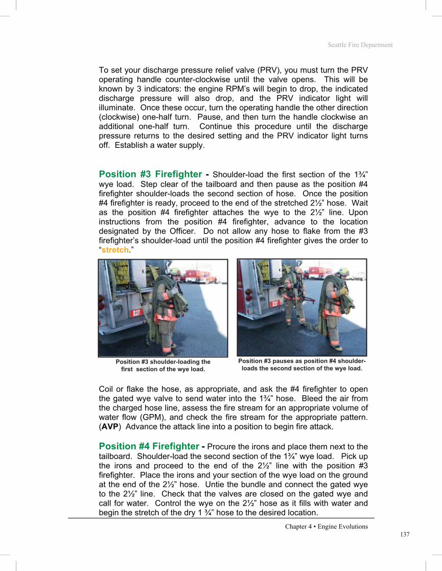
Position #3 Firefighter - Shoulder-load the first section of the 1¾”
wye load. Step clear of the tailboard and then pause as the position #4 firefighter shoulder-loads the second section of hose. Once the position #4 firefighter is ready, proceed to the end of the stretched 2½” hose. Wait as the position #4 firefighter attaches the wye to the 2½” line. Upon instructions from the position #4 firefighter, advance to the location designated by the Officer. Do not allow any hose to flake from the #3 firefighter’s shoulder-load until the position #4 firefighter gives the order to “stretch.”
PHOTO 4.22 PHOTO 4.23
Coil or flake the hose, as appropriate, and ask the #4 firefighter to open the gated wye valve to send water into the 1¾” hose. Bleed the air from the charged hose line, assess the fire stream for an appropriate volume of water flow (GPM), and check the fire stream for the appropriate pattern. (AVP) Advance the attack line into a position to begin fire attack.
Position #4 Firefighter - Procure the irons and place them next to the
tailboard. Shoulder-load the second section of the 1¾” wye load. Pick up the irons and proceed to the end of the 2½” line with the position #3 firefighter. Place the irons and your section of the wye load on the ground at the end of the 2½” hose. Untie the bundle and connect the gated wye to the 2½” line. Check that the valves are closed on the gated wye and call for water. Control the wye on the 2½” hose as it fills with water and begin the stretch of the dry 1 ¾” hose to the desired location.
Position #3 shoulder-loading the first section of the wye load.
Position #3 pauses as position #4 shoulder-loads the second section of the wye load.
Seattle Fire Department
Chapter 4 • Engine Evolutions
ENGINE COMPANY INTRODUCTION
Overview
Engine company hose evolutions will follow a department-wide standard. The goal is to provide the most efficient methods of performing fire ground operations. All members shall possess a solid understanding of the operations described within this section, as they will serve as the basis for engine company fire ground operations. These evolutions will be used to evaluate Recruit Firefighter’s during drill school and Operations Division member’s throughout their careers. In some instances, emergency situations may not be satisfactorily resolved by utilizing only these basic evolutions. The company Officer maintains the ability to alter these standard methods when necessary.
It should be noted that the Seattle Fire Department Basic Skills Manual is not a tactics textbook. The knowledge and decision-making skills must be learned and practiced using approved curriculum and methods.
Introduction
Stretching and operating hose lines is the primary function of the engine company. All members must realize the importance of the initial line stretched at a structural fire. More lives are saved at fire operations by the proper positioning and operating of hose lines than by all other life-saving techniques available to firefighting forces. The majority of structural fires are controlled and extinguished by this initial line. The first hose line is placed between the fire and any persons endangered by it. Often this is accomplished by stretching the line via the primary means of egress; usually the main entrance or stairway. The purpose of this line is to: • Allow occupants to evacuate • Allow members to proceed to the floors above the fire for search • Confine and extinguish the fire
If it is determined there is no life hazard in the building, the first line is positioned between the fire and the most severe exposure. This will likely be an internal exposure (within the fire building) in the case of an offensive fire attack or an adjacent building in the event of a defensive fire attack.

138
Seattle Fire Department
Chapter 4 • Engine Evolutions
NOTE: By obtaining water “to the wye” at this point, the driver will be free to obtain their supply and you are not relying on getting their attention at a later time to ask for water when the remainder of the stretch is complete.
PHOTO 4.24 PHOTO 4.25
If there are no obstacles, the #3 firefighter may be able to simply grab the center bight of the bundle on the ground and complete the stretch themselves (see Options for Stretching the Extended 1 ¾” Attack, in the next section). If there are obstacles (furniture, stairs, etc.), it may be necessary for the #4 firefighter to re-shoulder-load the remainder of the 1¾” hose. Be sure to pick up the irons and provide forcible entry as required. When the #3 firefighter asks for water to be sent into the 1 ¾” hose, open the appropriate gated wye valve and tie the valve in the open position. Cover with the SCBA. Assist in advancing and operating the hose line.
PHOTO 4.26 PHOTO 4.27
Position #4 connecting the gated wye to the 2 ½” hose.
Quarter-turn wye valve tied open.
Position #3 and #4 advancing with the wye load.
Single member stretch of the wye load.

139
Seattle Fire Department
Chapter 4 • Engine Evolutions
Options for Stretching the Extended 1 ¾” Atttack Line
All 1¾” hose to be used outside: Upon reaching the end of the 2½” line, the position #4 firefighter places the second section of the wye load neatly on the ground and unties the bundle. This firefighter then connects the gated wye to the 2½” hose. The position #3 firefighter grasps the center bight of the second section (on the ground) with the left hand while keeping the first section shoulder-loaded. The position #3 firefighter will then proceed to stretch all 200 feet of 1¾” hose. This firefighter should not drop any portion of the first section (shoulder-load) until all of the second section has been stretched out. After connecting the gated wye to the 2½” line, position #4 firefighter opens the appropriate valve at the call for water and then meets the other member at the nozzle.
If some of the 2 ½” hose will be used inside of the structure:
Upon reaching the end of the 2½” bundle (left bundled by the driver), the position #3 and #4 firefighters each grab two or three bights of 2½” hose with the left hand while retaining their wye load sections on their shoulder. The position #3 firefighter should grasp the bights most near to the 2½” male coupling (as well as the coupling itself), while position #4 firefighter grasps the remaining bights. As both members begin advancing the hose line to the objective, the position #4 firefighter will drop off flakes of 2½” hose first. When this firefighter drops the last flake, they should instruct the position #3 firefighter to “stretch the 2½.” The position #3 firefighter will then begin to drop flakes of 2½”.
PHOTO 4.28
Position #3 and #4 members stretching additional 2 ½” into the building.
Seattle Fire Department
Chapter 4 • Engine Evolutions
ENGINE COMPANY INTRODUCTION
Overview
Engine company hose evolutions will follow a department-wide standard. The goal is to provide the most efficient methods of performing fire ground operations. All members shall possess a solid understanding of the operations described within this section, as they will serve as the basis for engine company fire ground operations. These evolutions will be used to evaluate Recruit Firefighter’s during drill school and Operations Division member’s throughout their careers. In some instances, emergency situations may not be satisfactorily resolved by utilizing only these basic evolutions. The company Officer maintains the ability to alter these standard methods when necessary.
It should be noted that the Seattle Fire Department Basic Skills Manual is not a tactics textbook. The knowledge and decision-making skills must be learned and practiced using approved curriculum and methods.
Introduction
Stretching and operating hose lines is the primary function of the engine company. All members must realize the importance of the initial line stretched at a structural fire. More lives are saved at fire operations by the proper positioning and operating of hose lines than by all other life-saving techniques available to firefighting forces. The majority of structural fires are controlled and extinguished by this initial line. The first hose line is placed between the fire and any persons endangered by it. Often this is accomplished by stretching the line via the primary means of egress; usually the main entrance or stairway. The purpose of this line is to: • Allow occupants to evacuate • Allow members to proceed to the floors above the fire for search • Confine and extinguish the fire
If it is determined there is no life hazard in the building, the first line is positioned between the fire and the most severe exposure. This will likely be an internal exposure (within the fire building) in the case of an offensive fire attack or an adjacent building in the event of a defensive fire attack.
140
Seattle Fire Department
Chapter 4 • Engine Evolutions
Once all of the 2½” hose is deployed, the position #4 firefighter will connect the gated wye to the 2½” hose and the stretch will proceed as previously described.
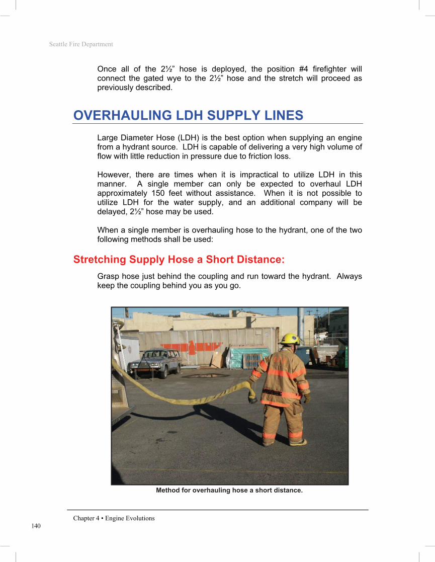
OVERHAULING LDH SUPPLY LINES Large Diameter Hose (LDH) is the best option when supplying an engine from a hydrant source. LDH is capable of delivering a very high volume of flow with little reduction in pressure due to friction loss. However, there are times when it is impractical to utilize LDH in this manner. A single member can only be expected to overhaul LDH approximately 150 feet without assistance. When it is not possible to utilize LDH for the water supply, and an additional company will be delayed, 2½” hose may be used. When a single member is overhauling hose to the hydrant, one of the two following methods shall be used:
Stretching Supply Hose a Short Distance:
Grasp hose just behind the coupling and run toward the hydrant. Always keep the coupling behind you as you go.
PHOTO 4.29
Method for overhauling hose a short distance.
141
Seattle Fire Department
Chapter 4 • Engine Evolutions
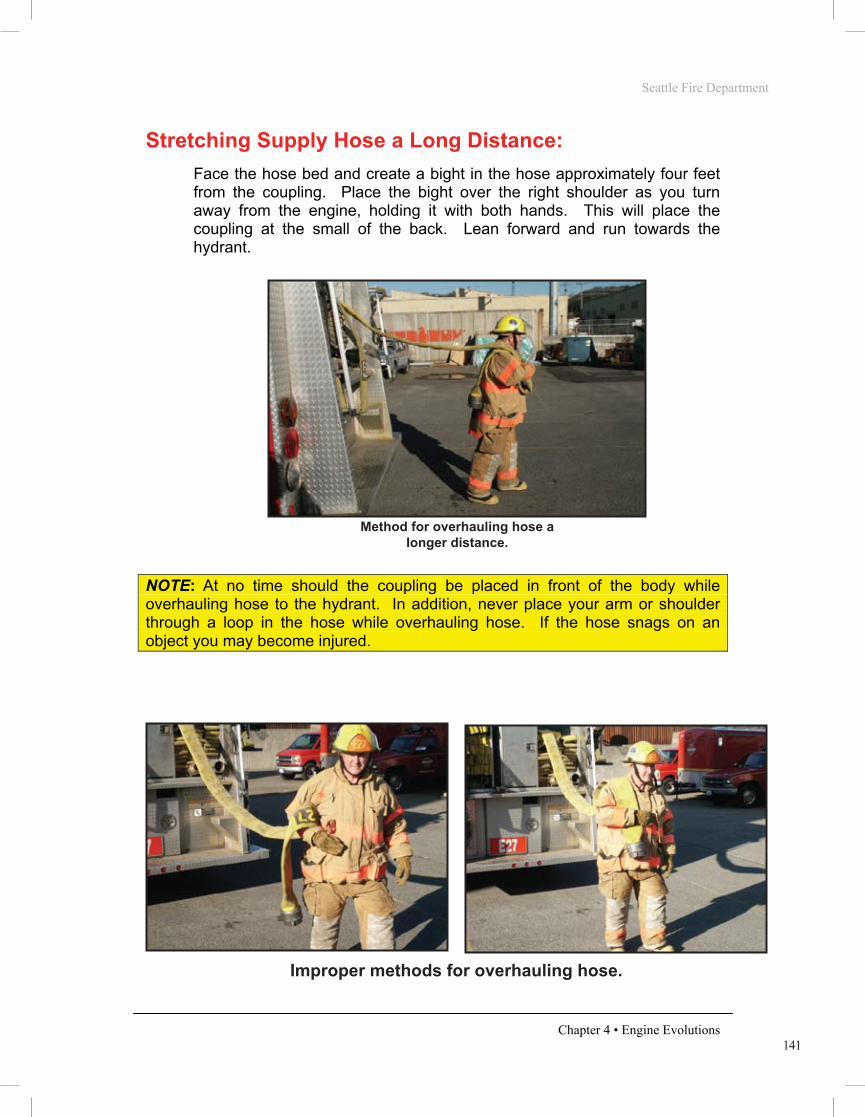
Stretching Supply Hose a Long Distance:
Face the hose bed and create a bight in the hose approximately four feet from the coupling. Place the bight over the right shoulder as you turn away from the engine, holding it with both hands. This will place the coupling at the small of the back. Lean forward and run towards the hydrant.
PHOTO 4.30
NOTE: At no time should the coupling be placed in front of the body while overhauling hose to the hydrant. In addition, never place your arm or shoulder through a loop in the hose while overhauling hose. If the hose snags on an object you may become injured.
PHOTO 4.31 PHOTO 4.32
Method for overhauling hose a longer distance.
Improper methods for overhauling hose.
Seattle Fire Department
Chapter 4 • Engine Evolutions
ENGINE COMPANY INTRODUCTION
Overview
Engine company hose evolutions will follow a department-wide standard. The goal is to provide the most efficient methods of performing fire ground operations. All members shall possess a solid understanding of the operations described within this section, as they will serve as the basis for engine company fire ground operations. These evolutions will be used to evaluate Recruit Firefighter’s during drill school and Operations Division member’s throughout their careers. In some instances, emergency situations may not be satisfactorily resolved by utilizing only these basic evolutions. The company Officer maintains the ability to alter these standard methods when necessary.
It should be noted that the Seattle Fire Department Basic Skills Manual is not a tactics textbook. The knowledge and decision-making skills must be learned and practiced using approved curriculum and methods.
Introduction
Stretching and operating hose lines is the primary function of the engine company. All members must realize the importance of the initial line stretched at a structural fire. More lives are saved at fire operations by the proper positioning and operating of hose lines than by all other life-saving techniques available to firefighting forces. The majority of structural fires are controlled and extinguished by this initial line. The first hose line is placed between the fire and any persons endangered by it. Often this is accomplished by stretching the line via the primary means of egress; usually the main entrance or stairway. The purpose of this line is to: • Allow occupants to evacuate • Allow members to proceed to the floors above the fire for search • Confine and extinguish the fire
If it is determined there is no life hazard in the building, the first line is positioned between the fire and the most severe exposure. This will likely be an internal exposure (within the fire building) in the case of an offensive fire attack or an adjacent building in the event of a defensive fire attack.

142
Seattle Fire Department
Chapter 4 • Engine Evolutions
Each Engine Company carries the following equipment to make connections to a hydrant in a dedicated hydrant bag. As a minimum, the hydrant bag will contain the following:
• Hydrant adapter (1) • 2 ½” double female (1) • Body loop (1) • OCD wrench (1) • Spanner wrench (2) • Hydrant gate (1) • 2½” to 4” Increaser (1) – (typically kept attached to the hydrant gate)
PHOTO 4.33
LDH Supply to the Rear of the Engine If the nearest hydrant is to the rear of the engine, disconnect the LDH from the tri-gate and overhaul the hose directly to the hydrant. Proceed approximately 6 feet past the hydrant to allow enough hose for an easy connection. Leave the female coupling at the hydrant and return to the engine.
PHOTO 4.34 PHOTO 4.35
Hydrant Bag contents.
Driver pulling hose straight back Pulling until enough hose to reach the side intake is removed.

143
Seattle Fire Department
Chapter 4 • Engine Evolutions
Grasp the LDH where it comes down from the hose bed. Turn and run out the hose at a slight angle until a coupling, that will reach the desired pump intake, drops to the ground Return to that coupling, break the connection, and place the female end of the unused hose under the tailboard to minimize the tripping hazard.
PHOTO 4.36 PHOTO 4.37
Attach the male end of the LDH to the desired pump intake using a 4” double female. (If the soft suction hose is connected to the intake, remove it to allow for this connection to be made). Open the intake valve.
PHOTO 4.38
Breaking the connection of LDH that will reach the side intake.
Placing the unused end of the LDH under the tailboard.
Making the connection to the intake with a 4” double female coupling.
Seattle Fire Department
Chapter 4 • Engine Evolutions
ENGINE COMPANY INTRODUCTION
Overview
Engine company hose evolutions will follow a department-wide standard. The goal is to provide the most efficient methods of performing fire ground operations. All members shall possess a solid understanding of the operations described within this section, as they will serve as the basis for engine company fire ground operations. These evolutions will be used to evaluate Recruit Firefighter’s during drill school and Operations Division member’s throughout their careers. In some instances, emergency situations may not be satisfactorily resolved by utilizing only these basic evolutions. The company Officer maintains the ability to alter these standard methods when necessary.
It should be noted that the Seattle Fire Department Basic Skills Manual is not a tactics textbook. The knowledge and decision-making skills must be learned and practiced using approved curriculum and methods.
Introduction
Stretching and operating hose lines is the primary function of the engine company. All members must realize the importance of the initial line stretched at a structural fire. More lives are saved at fire operations by the proper positioning and operating of hose lines than by all other life-saving techniques available to firefighting forces. The majority of structural fires are controlled and extinguished by this initial line. The first hose line is placed between the fire and any persons endangered by it. Often this is accomplished by stretching the line via the primary means of egress; usually the main entrance or stairway. The purpose of this line is to: • Allow occupants to evacuate • Allow members to proceed to the floors above the fire for search • Confine and extinguish the fire
If it is determined there is no life hazard in the building, the first line is positioned between the fire and the most severe exposure. This will likely be an internal exposure (within the fire building) in the case of an offensive fire attack or an adjacent building in the event of a defensive fire attack.

144
Seattle Fire Department
Chapter 4 • Engine Evolutions
Procure the hydrant bag and hydrant wrenches and return to the hydrant.
PHOTO 4.39
Remove the 4” engine port cap and a 2½” port cap of the hydrant with a corey wrench. Attach the hydrant adapter to the engine port and the LDH to the hydrant adapter. Attach the hydrant gate to the 2½” port and ensure that the gate is in the closed position.
PHOTO 4.40
Returning to the hydrant with the hydrant bag and wrenches.
Hydrant Adaptor used to connect LDH to the hydrant.
145
Seattle Fire Department
Chapter 4 • Engine Evolutions
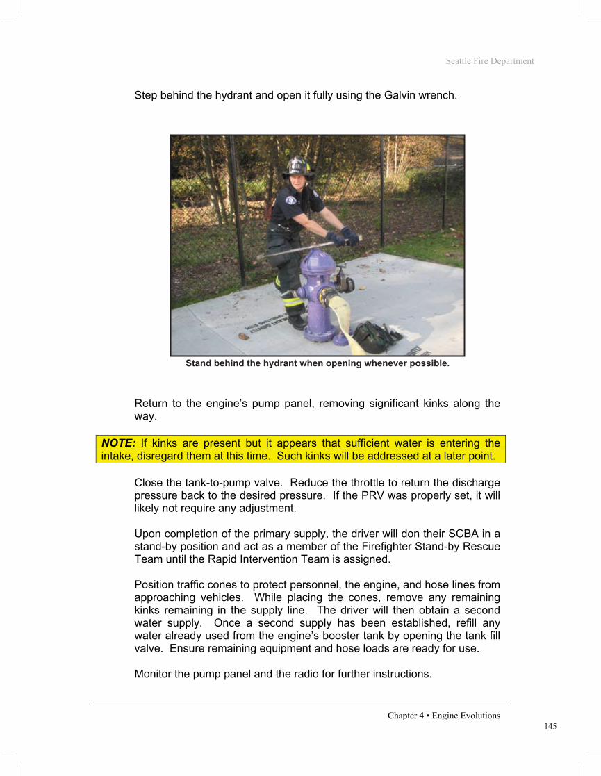
Step behind the hydrant and open it fully using the Galvin wrench.
PHOTO 4.41
Return to the engine’s pump panel, removing significant kinks along the way.
NOTE: If kinks are present but it appears that sufficient water is entering the intake, disregard them at this time. Such kinks will be addressed at a later point.
Close the tank-to-pump valve. Reduce the throttle to return the discharge pressure back to the desired pressure. If the PRV was properly set, it will likely not require any adjustment. Upon completion of the primary supply, the driver will don their SCBA in a stand-by position and act as a member of the Firefighter Stand-by Rescue Team until the Rapid Intervention Team is assigned. Position traffic cones to protect personnel, the engine, and hose lines from approaching vehicles. While placing the cones, remove any remaining kinks remaining in the supply line. The driver will then obtain a second water supply. Once a second supply has been established, refill any water already used from the engine’s booster tank by opening the tank fill valve. Ensure remaining equipment and hose loads are ready for use. Monitor the pump panel and the radio for further instructions.
Stand behind the hydrant when opening whenever possible.
Seattle Fire Department
Chapter 4 • Engine Evolutions
ENGINE COMPANY INTRODUCTION
Overview
Engine company hose evolutions will follow a department-wide standard. The goal is to provide the most efficient methods of performing fire ground operations. All members shall possess a solid understanding of the operations described within this section, as they will serve as the basis for engine company fire ground operations. These evolutions will be used to evaluate Recruit Firefighter’s during drill school and Operations Division member’s throughout their careers. In some instances, emergency situations may not be satisfactorily resolved by utilizing only these basic evolutions. The company Officer maintains the ability to alter these standard methods when necessary.
It should be noted that the Seattle Fire Department Basic Skills Manual is not a tactics textbook. The knowledge and decision-making skills must be learned and practiced using approved curriculum and methods.
Introduction
Stretching and operating hose lines is the primary function of the engine company. All members must realize the importance of the initial line stretched at a structural fire. More lives are saved at fire operations by the proper positioning and operating of hose lines than by all other life-saving techniques available to firefighting forces. The majority of structural fires are controlled and extinguished by this initial line. The first hose line is placed between the fire and any persons endangered by it. Often this is accomplished by stretching the line via the primary means of egress; usually the main entrance or stairway. The purpose of this line is to: • Allow occupants to evacuate • Allow members to proceed to the floors above the fire for search • Confine and extinguish the fire
If it is determined there is no life hazard in the building, the first line is positioned between the fire and the most severe exposure. This will likely be an internal exposure (within the fire building) in the case of an offensive fire attack or an adjacent building in the event of a defensive fire attack.

146
Seattle Fire Department
Chapter 4 • Engine Evolutions
LDH Supply to the Front of the Engine
If the nearest hydrant is to the front of the engine, disconnect the LDH from the tri-gate and overhaul the hose straight back from the hose bed until the first coupling drops to the ground.
PHOTO 4.42
While maintaining the female coupling, return to the rear corner of the engine (on the same side of the engine as the intended hydrant is on).
PHOTO 4.43
Stretching straight back until the first coupling drops.
Driver returning to the engine with the first coupling.

147
Seattle Fire Department
Chapter 4 • Engine Evolutions
Place the female coupling even with the tailboard on the side of the engine. Return to the tailboard, grasp the next section of LDH just behind the second coupling, and again overhaul the hose directly to the rear until a third coupling is pulled from the hose bed. Bring the second coupling (currently in your hand) back to the engine and place it next to the coupling that was originally connected to the tri-gate. This creates a big “W”. Repeat this procedure until enough LDH has been removed from the hose bed to reach the hydrant.
PHOTO 4.44 PHOTO 4.45
PHOTO 4.46
Driver returning to the tailboard to stretch a second section.
Driver stretching a second section of LDH completely out.
The next coupling is again brought back to the tailboard. (The Big “W”)
Seattle Fire Department
Chapter 4 • Engine Evolutions
ENGINE COMPANY INTRODUCTION
Overview
Engine company hose evolutions will follow a department-wide standard. The goal is to provide the most efficient methods of performing fire ground operations. All members shall possess a solid understanding of the operations described within this section, as they will serve as the basis for engine company fire ground operations. These evolutions will be used to evaluate Recruit Firefighter’s during drill school and Operations Division member’s throughout their careers. In some instances, emergency situations may not be satisfactorily resolved by utilizing only these basic evolutions. The company Officer maintains the ability to alter these standard methods when necessary.
It should be noted that the Seattle Fire Department Basic Skills Manual is not a tactics textbook. The knowledge and decision-making skills must be learned and practiced using approved curriculum and methods.
Introduction
Stretching and operating hose lines is the primary function of the engine company. All members must realize the importance of the initial line stretched at a structural fire. More lives are saved at fire operations by the proper positioning and operating of hose lines than by all other life-saving techniques available to firefighting forces. The majority of structural fires are controlled and extinguished by this initial line. The first hose line is placed between the fire and any persons endangered by it. Often this is accomplished by stretching the line via the primary means of egress; usually the main entrance or stairway. The purpose of this line is to: • Allow occupants to evacuate • Allow members to proceed to the floors above the fire for search • Confine and extinguish the fire
If it is determined there is no life hazard in the building, the first line is positioned between the fire and the most severe exposure. This will likely be an internal exposure (within the fire building) in the case of an offensive fire attack or an adjacent building in the event of a defensive fire attack.
148
Seattle Fire Department
Chapter 4 • Engine Evolutions
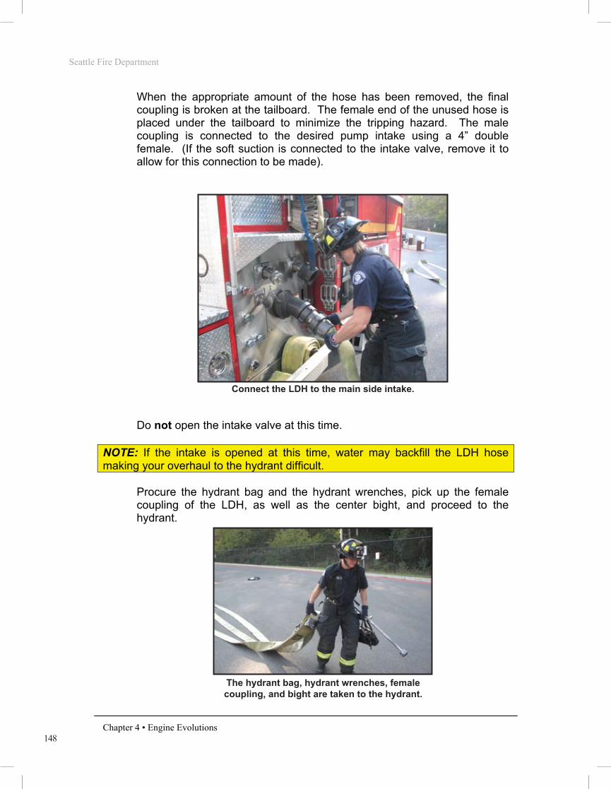
When the appropriate amount of the hose has been removed, the final coupling is broken at the tailboard. The female end of the unused hose is placed under the tailboard to minimize the tripping hazard. The male coupling is connected to the desired pump intake using a 4” double female. (If the soft suction is connected to the intake valve, remove it to allow for this connection to be made).
PHOTO 4.47
Do not open the intake valve at this time.
NOTE: If the intake is opened at this time, water may backfill the LDH hose making your overhaul to the hydrant difficult.
Procure the hydrant bag and the hydrant wrenches, pick up the female coupling of the LDH, as well as the center bight, and proceed to the hydrant.
PHOTO 4.48
The hydrant bag, hydrant wrenches, female coupling, and bight are taken to the hydrant.
Connect the LDH to the main side intake.

149
Seattle Fire Department
Chapter 4 • Engine Evolutions
Remove the 4” engine port cap and a 2½” port cap of the hydrant with a corey wrench. Attach the hydrant adapter to the engine port and the LDH to the adapter.
Photo 4.49
Attach the hydrant gate to the 2½” port and ensure that the gate is in the closed position. Step behind the hydrant and open it fully using the Galvin wrench.
PHOTO 4.50
Hydrant Adaptor used to connect LDH to the hydrant.
Opening the hydrant.
Seattle Fire Department
Chapter 4 • Engine Evolutions
ENGINE COMPANY INTRODUCTION
Overview
Engine company hose evolutions will follow a department-wide standard. The goal is to provide the most efficient methods of performing fire ground operations. All members shall possess a solid understanding of the operations described within this section, as they will serve as the basis for engine company fire ground operations. These evolutions will be used to evaluate Recruit Firefighter’s during drill school and Operations Division member’s throughout their careers. In some instances, emergency situations may not be satisfactorily resolved by utilizing only these basic evolutions. The company Officer maintains the ability to alter these standard methods when necessary.
It should be noted that the Seattle Fire Department Basic Skills Manual is not a tactics textbook. The knowledge and decision-making skills must be learned and practiced using approved curriculum and methods.
Introduction
Stretching and operating hose lines is the primary function of the engine company. All members must realize the importance of the initial line stretched at a structural fire. More lives are saved at fire operations by the proper positioning and operating of hose lines than by all other life-saving techniques available to firefighting forces. The majority of structural fires are controlled and extinguished by this initial line. The first hose line is placed between the fire and any persons endangered by it. Often this is accomplished by stretching the line via the primary means of egress; usually the main entrance or stairway. The purpose of this line is to: • Allow occupants to evacuate • Allow members to proceed to the floors above the fire for search • Confine and extinguish the fire
If it is determined there is no life hazard in the building, the first line is positioned between the fire and the most severe exposure. This will likely be an internal exposure (within the fire building) in the case of an offensive fire attack or an adjacent building in the event of a defensive fire attack.

150
Seattle Fire Department
Chapter 4 • Engine Evolutions
Return to the engine’s pump panel. If a significant kink is found while returning to the pump panel remove it immediately. If kinks are present but it remains evident that sufficient water will enter the intake, disregard them at this time. Such kinks will be addressed at a later point. Once at the pump panel, open the intake valve. Close the tank-to-pump valve. Adjust the throttle to return the discharge pressure back to the desired operating pressure. If the PRV was properly set, it will likely not require any adjustment.
Upon completion of the primary supply, the driver will don SCBA to a stand-by position and act as a member of the Firefighter Stand-by Rescue Team if one is not already in place and a Rapid Intervention Team has not yet been assigned. Position traffic cones to protect personnel, the engine, and hose lines from approaching vehicles. While placing the cones, remove any remaining kinks in the supply line. The driver will then obtain a second water supply. Once a second supply has been established, refill any water already used from the engine’s booster tank by opening the tank fill valve. Ensure remaining equipment and hose loads are ready for use. Monitor the pump panel and the radio for further instructions.

151
Seattle Fire Department
Chapter 4 • Engine Evolutions
2½” Supply
NOTE: This option should be used only if no LDH is available or the overhaul distance is greater than 150 feet and an additional company is delayed. This should only be used if the required initial water flow is expected to be 300 GPM or less.
Hydrant to the rear of the engine (less than 150 feet away)
If a 2 ½” supply is to be overhauled, begin by releasing the tie rope from the first section of 2½” hose in the reverse bed. Then, grasp the nozzle or the male end of the 2½” and step down from the tailboard. Make a bight four feet from the male coupling and place the bight over the shoulder. The nozzle and/or the male coupling should be at the small of your back. Overhaul the hose directly to the hydrant.
PHOTO 4.51
When the hydrant is reached, proceed approximately 6 feet past the hydrant to allow enough hose for an easy connection. Place the nozzle or male coupling on the ground and return to the engine. Break the next coupling in the 2½” reverse bed that will reach the desired intake port. Connect the female coupling to the 2½” intake using a 2½” double male. Open the intake valve.
NOTE: The 2½” supply could be attached to the main side intake with a 4” to 2½” reducer. However, if the fire is an “evolving” incident, the 2½” supply will need to be augmented by an LDH supply which is much more efficient. Therefore, the main intake should be left available for that connection.
Procure the hydrant bag, the hydrant wrenches, and then proceed to the hydrant. Remove both hydrant’s 2½” port caps with the Corey wrench.
Driver overhauling 2 ½” hose to hydrant.
Seattle Fire Department
Chapter 4 • Engine Evolutions
ENGINE COMPANY INTRODUCTION
Overview
Engine company hose evolutions will follow a department-wide standard. The goal is to provide the most efficient methods of performing fire ground operations. All members shall possess a solid understanding of the operations described within this section, as they will serve as the basis for engine company fire ground operations. These evolutions will be used to evaluate Recruit Firefighter’s during drill school and Operations Division member’s throughout their careers. In some instances, emergency situations may not be satisfactorily resolved by utilizing only these basic evolutions. The company Officer maintains the ability to alter these standard methods when necessary.
It should be noted that the Seattle Fire Department Basic Skills Manual is not a tactics textbook. The knowledge and decision-making skills must be learned and practiced using approved curriculum and methods.
Introduction
Stretching and operating hose lines is the primary function of the engine company. All members must realize the importance of the initial line stretched at a structural fire. More lives are saved at fire operations by the proper positioning and operating of hose lines than by all other life-saving techniques available to firefighting forces. The majority of structural fires are controlled and extinguished by this initial line. The first hose line is placed between the fire and any persons endangered by it. Often this is accomplished by stretching the line via the primary means of egress; usually the main entrance or stairway. The purpose of this line is to: • Allow occupants to evacuate • Allow members to proceed to the floors above the fire for search • Confine and extinguish the fire
If it is determined there is no life hazard in the building, the first line is positioned between the fire and the most severe exposure. This will likely be an internal exposure (within the fire building) in the case of an offensive fire attack or an adjacent building in the event of a defensive fire attack.

152
Seattle Fire Department
Chapter 4 • Engine Evolutions
Attach the hydrant gate to the non-fire side of hydrant and ensure that the gate is in the closed position. Attach the 2½” hose on the fire side of the hydrant utilizing the 2½” double female. Step behind the hydrant and open it fully with the Galvin wrench.
PHOTO 4.52
Return to the engine’s pump panel with the detached 2½” nozzle. If a significant kink is discovered, remove it immediately. If kinks are present but sufficient water is entering the intake, disregard them at this time. Such kinks will be addressed at a later point. Once at the pump panel, close the tank-to-pump valve. Adjust the throttle to return the discharge pressure back to the desired operating pressure. If the pressure relief valve was properly set, it will likely not require any adjustment. Upon completion of the initial supply, the driver will don their SCBA to a stand-by position and act as a member of the Firefighter Stand-by Rescue Team if one is not already in place. Position traffic cones to protect personnel, the engine, and hose lines from approaching vehicles. While placing the cones, remove any remaining kinks in the supply line. The driver will then obtain a second water supply. This should be an LDH supply since there is now time to properly obtain one. Once a second supply has been established, refill any water already used from the engine’s booster tank by opening the tank fill valve. Ensure remaining equipment and hose loads are ready for use. Monitor the pump panel and the radio for further instructions.
2 ½” supply on the fire side of the hydrant.

153
Seattle Fire Department
Chapter 4 • Engine Evolutions
Hydrant to the rear of the engine (more than 150 feet away) If a 2 ½” supply is to be overhauled more than 150 feet away to the rear of the engine, shoulder-load the first section of 2½” hose from the reverse bed. Then, step down from the tailboard and pull the hose out until the first coupling clears the hose bed. Turn to the left and, with your left hand, grasp the center flake of the next section (for a 200 foot stretch) or the first marker bight (for a 300 foot stretch). Proceed to the hydrant. Release the bight when the hose has been pulled from the bed. Then, release the tie-rope on the 2 ½” shoulder-load and continue the stretch utilizing the shoulder-loaded hose to reach the hydrant. The hydrant connections and pump panel procedures are then the same as the “Hydrant to the rear (less than 150 feet away)” evolution.
PHOTO 4.53 PHOTO 4.54
Hydrant in front of the engine If a 2 ½” supply is to be overhauled to the front of the engine, shoulder-load the first section of 2½” hose from the reverse bed. Then, step down from the tailboard and pull the hose until the next coupling clears the hose bed. Turn to the left and, with your left hand, grasp the center flake of the next section (for a 200 foot stretch) or the marker bight (for a 300 foot stretch). Stretch out the second section of 2½” hose (and third if necessary) directly to the rear of the engine. Without dropping any hose, proceed back to the engine. Continue to the hydrant, letting go of the bight at the appropriate time. Then, release the tie-rope on the 2 ½” shoulder-load and continue the stretch utilizing the shoulder load to reach the hydrant. The hydrant connections and pump panel procedures are then the same as the “Hydrant to the rear (less than 150 feet away)” evolution.
Grasp the center flake for a 200 foot stretch Grasp the marker bight for a 300 foot stretch
Seattle Fire Department
Chapter 4 • Engine Evolutions
ENGINE COMPANY INTRODUCTION
Overview
Engine company hose evolutions will follow a department-wide standard. The goal is to provide the most efficient methods of performing fire ground operations. All members shall possess a solid understanding of the operations described within this section, as they will serve as the basis for engine company fire ground operations. These evolutions will be used to evaluate Recruit Firefighter’s during drill school and Operations Division member’s throughout their careers. In some instances, emergency situations may not be satisfactorily resolved by utilizing only these basic evolutions. The company Officer maintains the ability to alter these standard methods when necessary.
It should be noted that the Seattle Fire Department Basic Skills Manual is not a tactics textbook. The knowledge and decision-making skills must be learned and practiced using approved curriculum and methods.
Introduction
Stretching and operating hose lines is the primary function of the engine company. All members must realize the importance of the initial line stretched at a structural fire. More lives are saved at fire operations by the proper positioning and operating of hose lines than by all other life-saving techniques available to firefighting forces. The majority of structural fires are controlled and extinguished by this initial line. The first hose line is placed between the fire and any persons endangered by it. Often this is accomplished by stretching the line via the primary means of egress; usually the main entrance or stairway. The purpose of this line is to: • Allow occupants to evacuate • Allow members to proceed to the floors above the fire for search • Confine and extinguish the fire
If it is determined there is no life hazard in the building, the first line is positioned between the fire and the most severe exposure. This will likely be an internal exposure (within the fire building) in the case of an offensive fire attack or an adjacent building in the event of a defensive fire attack.

154
Seattle Fire Department
Chapter 4 • Engine Evolutions
Obtaining a Second Supply A second supply line from a hydrant source is required when any of the following apply:
1. If supplying a 2½” attack line 2. If pumping 300 gallons per minute or more 3. While pumping at any multiple alarm fire
It should be noted that a second supply is highly recommended whenever operating at a working fire or other hazardous environment even if the above rules do not apply. A greater margin of safety is provided with redundant supply lines. Similar to the primary supply line, second supplies will utilize the largest diameter hose available. In addition, the methods for obtaining the second supply will be the same as for the primary supply line. The specific procedures will vary only slightly, as indicated below:
• Do not open the intake valve for the second supply until that line has been connected to the hydrant and charged.
NOTE: If the intake is opened before the hydrant connection is made, water will abruptly backfill the hose making your connection to the hydrant impossible.
• If using 2 ½” as the second supply, remove the 2 ½” to 4” increaser from
the hydrant gate and connect the female end of the 2 ½ ” hose to the hydrant gate. (LDH is always preferred for a second supply)
• Remove all kinks in the second supply line as the hose is followed back to the engine from the hydrant.
REVERSE LAY VARIATIONS For a reverse lay, a large compliment of hose and equipment must be removed from the engine at the fire scene. This task must be completed before the engine can proceed to the hydrant. Because of this, the removal of hose and equipment from the engine must be accomplished as quickly and as efficiently as possible. Therefore, the positional assignments regarding the removal of specific hose bundles are only recommendations. Members should always work together to remove the required hose compliment in the manner most efficient for the situation at hand.
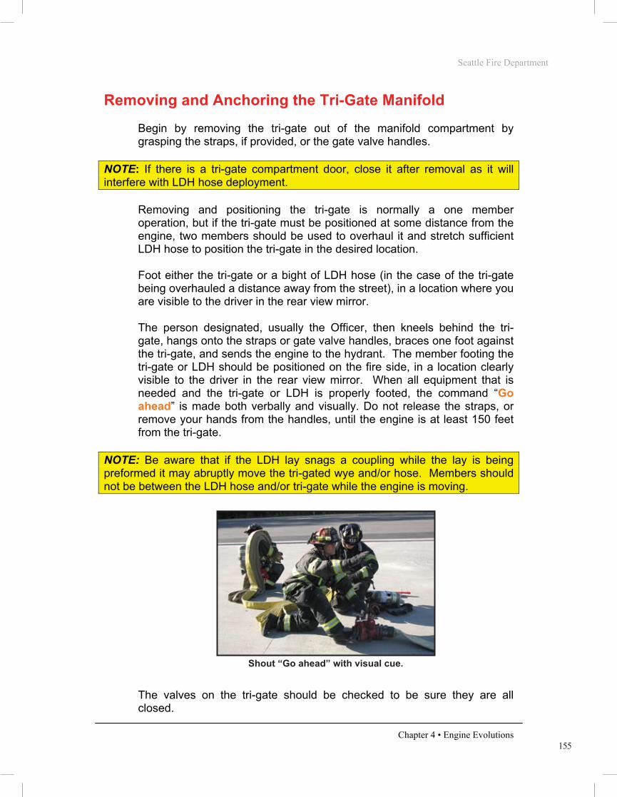
155
Seattle Fire Department
Chapter 4 • Engine Evolutions
Removing and Anchoring the Tri-Gate Manifold Begin by removing the tri-gate out of the manifold compartment by grasping the straps, if provided, or the gate valve handles.
NOTE: If there is a tri-gate compartment door, close it after removal as it will interfere with LDH hose deployment.
Removing and positioning the tri-gate is normally a one member operation, but if the tri-gate must be positioned at some distance from the engine, two members should be used to overhaul it and stretch sufficient LDH hose to position the tri-gate in the desired location. Foot either the tri-gate or a bight of LDH hose (in the case of the tri-gate being overhauled a distance away from the street), in a location where you are visible to the driver in the rear view mirror. The person designated, usually the Officer, then kneels behind the tri-gate, hangs onto the straps or gate valve handles, braces one foot against the tri-gate, and sends the engine to the hydrant. The member footing the tri-gate or LDH should be positioned on the fire side, in a location clearly visible to the driver in the rear view mirror. When all equipment that is needed and the tri-gate or LDH is properly footed, the command “Go ahead” is made both verbally and visually. Do not release the straps, or remove your hands from the handles, until the engine is at least 150 feet from the tri-gate.
NOTE: Be aware that if the LDH lay snags a coupling while the lay is being preformed it may abruptly move the tri-gated wye and/or hose. Members should not be between the LDH hose and/or tri-gate while the engine is moving.
PHOTO 4.55
The valves on the tri-gate should be checked to be sure they are all closed.
Shout “Go ahead” with visual cue.
Seattle Fire Department
Chapter 4 • Engine Evolutions
ENGINE COMPANY INTRODUCTION
Overview
Engine company hose evolutions will follow a department-wide standard. The goal is to provide the most efficient methods of performing fire ground operations. All members shall possess a solid understanding of the operations described within this section, as they will serve as the basis for engine company fire ground operations. These evolutions will be used to evaluate Recruit Firefighter’s during drill school and Operations Division member’s throughout their careers. In some instances, emergency situations may not be satisfactorily resolved by utilizing only these basic evolutions. The company Officer maintains the ability to alter these standard methods when necessary.
It should be noted that the Seattle Fire Department Basic Skills Manual is not a tactics textbook. The knowledge and decision-making skills must be learned and practiced using approved curriculum and methods.
Introduction
Stretching and operating hose lines is the primary function of the engine company. All members must realize the importance of the initial line stretched at a structural fire. More lives are saved at fire operations by the proper positioning and operating of hose lines than by all other life-saving techniques available to firefighting forces. The majority of structural fires are controlled and extinguished by this initial line. The first hose line is placed between the fire and any persons endangered by it. Often this is accomplished by stretching the line via the primary means of egress; usually the main entrance or stairway. The purpose of this line is to: • Allow occupants to evacuate • Allow members to proceed to the floors above the fire for search • Confine and extinguish the fire
If it is determined there is no life hazard in the building, the first line is positioned between the fire and the most severe exposure. This will likely be an internal exposure (within the fire building) in the case of an offensive fire attack or an adjacent building in the event of a defensive fire attack.

156
Seattle Fire Department
Chapter 4 • Engine Evolutions
1¾” Manifold The 1¾” Manifold evolution will result in members removing the wye load (200 feet of 1¾” attack line), the tri-gate with LDH attached, and appropriate tools from the engine at the fire location. The engine will then perform a reverse lay to the hydrant.
PHOTO 4.56
NOTE: If more than 200 feet of attack line will be needed to reach the objective from the manifold’s position, sufficient 2½” hose will also be removed from the engine to extend the 200 feet of 1¾” attack line. See instructions for the “Extended 1¾” Manifold.”
Officer - Direct the driver where to position the engine. Give verbal
directions to the crew designating the evolution to be performed, and the destination of the hose line (e.g. “1¾ manifold to the front door”). Remove the Officer’s SCBA and appropriate tools from the engine and place these items on the ground. If possible, assist in removing the necessary hose. Ensure that all required hose and equipment for the evolution has been removed from the engine. Kneel at the tri-gate and send the engine to the hydrant. This signal should be both audible and visual, by pointing forward while shouting “Go ahead.” (The removal of the tri-gate and it’s footing may be assigned to the position #4 firefighter if the Officer has command duties to attend to).
1 ¾” Manifold, before the lay
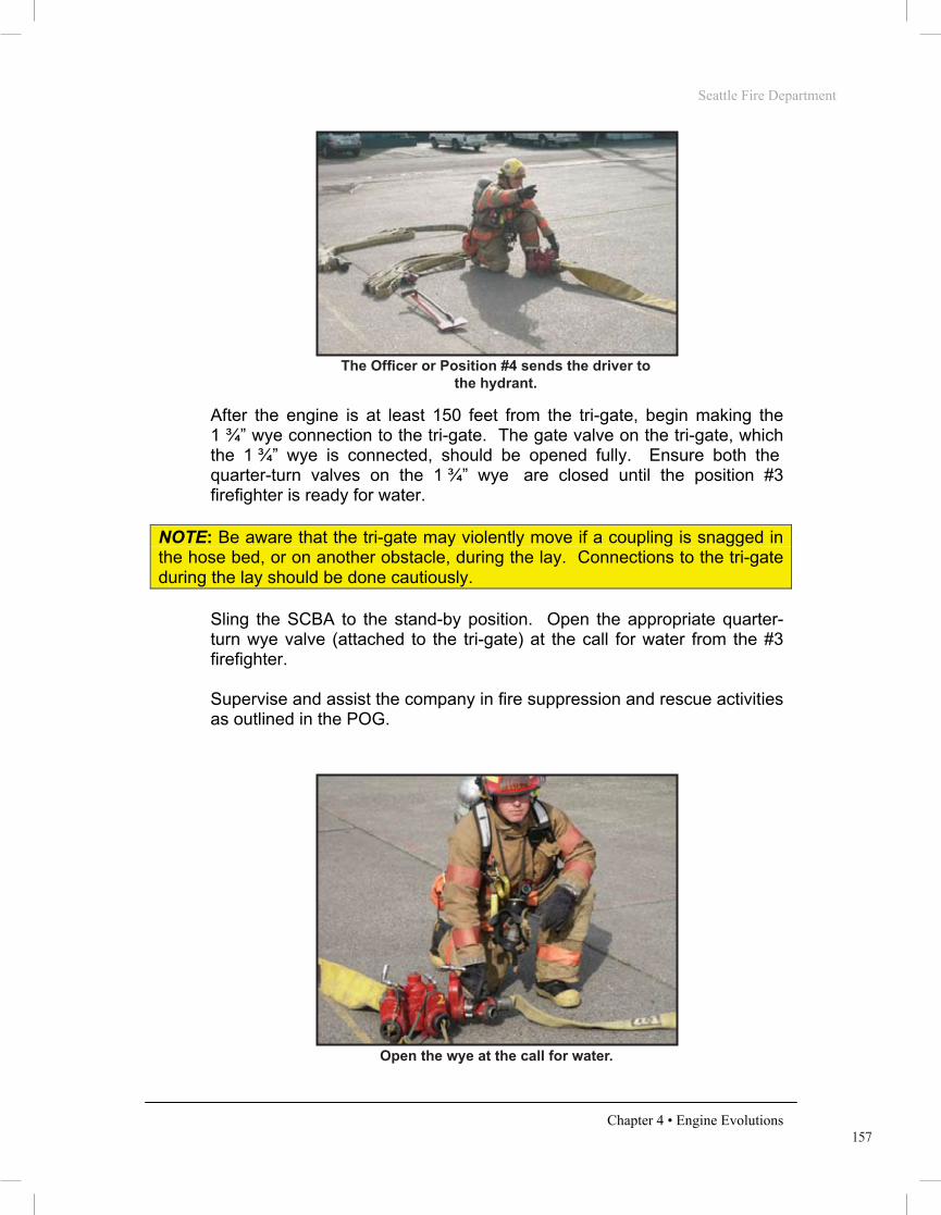
157
Seattle Fire Department
Chapter 4 • Engine Evolutions
PHOTO 4.57
After the engine is at least 150 feet from the tri-gate, begin making the 1 ¾” wye connection to the tri-gate. The gate valve on the tri-gate, which the 1 ¾” wye is connected, should be opened fully. Ensure both the quarter-turn valves on the 1 ¾” wye are closed until the position #3 firefighter is ready for water.
NOTE: Be aware that the tri-gate may violently move if a coupling is snagged in the hose bed, or on another obstacle, during the lay. Connections to the tri-gate during the lay should be done cautiously.
Sling the SCBA to the stand-by position. Open the appropriate quarter-turn wye valve (attached to the tri-gate) at the call for water from the #3 firefighter. Supervise and assist the company in fire suppression and rescue activities as outlined in the POG.
PHOTO 4.58
The Officer or Position #4 sends the driver to the hydrant.
Open the wye at the call for water.
Seattle Fire Department
Chapter 4 • Engine Evolutions
ENGINE COMPANY INTRODUCTION
Overview
Engine company hose evolutions will follow a department-wide standard. The goal is to provide the most efficient methods of performing fire ground operations. All members shall possess a solid understanding of the operations described within this section, as they will serve as the basis for engine company fire ground operations. These evolutions will be used to evaluate Recruit Firefighter’s during drill school and Operations Division member’s throughout their careers. In some instances, emergency situations may not be satisfactorily resolved by utilizing only these basic evolutions. The company Officer maintains the ability to alter these standard methods when necessary.
It should be noted that the Seattle Fire Department Basic Skills Manual is not a tactics textbook. The knowledge and decision-making skills must be learned and practiced using approved curriculum and methods.
Introduction
Stretching and operating hose lines is the primary function of the engine company. All members must realize the importance of the initial line stretched at a structural fire. More lives are saved at fire operations by the proper positioning and operating of hose lines than by all other life-saving techniques available to firefighting forces. The majority of structural fires are controlled and extinguished by this initial line. The first hose line is placed between the fire and any persons endangered by it. Often this is accomplished by stretching the line via the primary means of egress; usually the main entrance or stairway. The purpose of this line is to: • Allow occupants to evacuate • Allow members to proceed to the floors above the fire for search • Confine and extinguish the fire
If it is determined there is no life hazard in the building, the first line is positioned between the fire and the most severe exposure. This will likely be an internal exposure (within the fire building) in the case of an offensive fire attack or an adjacent building in the event of a defensive fire attack.

158
Seattle Fire Department
Chapter 4 • Engine Evolutions
Driver - See instructions for the Reverse Pump Hook-up.
Position #3 Firefighter - Remove each section of the 1¾” wye load
and place them on the ground and to the fire side of the engine.
NOTE: If the wye load is properly tied, it is possible to remove the entire bundle like a preconnect. If this does not seem possible, remove one section at a time, attempting to keep the individual bundles intact.
The nozzle section should be nearest to the fire. Give the gated wye to the position #4 firefighter so the connection to the tri-gate can be made.
PHOTO 4.59
Re-shoulder-load the nozzle bundle of the wye load, and wait as the position #4 firefighter shoulder-loads the second section.
NOTE: The entire 1¾” wye load can be stretched by the #3 firefighter if the members are confident that there will not be difficulties in making the stretch due to obstacles, stairs, etc. This should be done by reaching back with the left hand and grabbing a center bight of the second section of the 1 ¾” wye line while maintaining the shoulder-loaded nozzle section.
When directed by the position #4 firefighter, proceed to the designated objective. Do not allow any hose to flake from the shoulder-load until position #4 gives the order to “stretch.” Coil or flake the hose, as appropriate, and call for water. Cover with the SCBA. Bleed the air from the charged hose line, assess the fire stream
Handing off the gated wye to the position #4 firefighter.

159
Seattle Fire Department
Chapter 4 • Engine Evolutions
for an appropriate volume of water flow (GPM), and check the fire stream for the appropriate pattern. (AVP) Advance the attack line into a position to begin the fire attack.
Position #4 Firefighter - Procure the irons and place them on the
ground and to the fire side of the engine. Remove the tri-gate and position it between the unloaded 1¾” wye bundles and the engine. If the Officer directs the #4 firefighter to, foot the tri-gate and ensure that all required hose and equipment has been removed from the engine. Then, signal the driver to proceed to the hydrant. This signal should be both audible and visual, by pointing forward while shouting “Go ahead.”
NOTE: If the Officer is unable to foot the tri-gate or LDH because of incident command responsibilities, the position #4 firefighter will have sole responsibility of ensuring that all required hose and equipment has been removed from the engine. After completing this task, position #4 firefighter will then direct the driver to proceed to the hydrant without instructions from the Officer.
PHOTO 4.60
After the engine is at least 150 feet from the tri-gate, begin making the 1 ¾” wye connection to the tri-gate. The gate valve on the tri-gate which the 1 ¾” wye is connected should, at this point, be opened fully. Do not open the 1 ¾” wye quarter-turn valve.
NOTE: Be aware that the tri-gate may violently move if a coupling is snagged in the hose bed, or on another obstacle, during the lay. Connections to the tri-gate during the lay should be done cautiously.
The Officer or Position #4 sends the driver to the hydrant.
Seattle Fire Department
Chapter 4 • Engine Evolutions
ENGINE COMPANY INTRODUCTION
Overview
Engine company hose evolutions will follow a department-wide standard. The goal is to provide the most efficient methods of performing fire ground operations. All members shall possess a solid understanding of the operations described within this section, as they will serve as the basis for engine company fire ground operations. These evolutions will be used to evaluate Recruit Firefighter’s during drill school and Operations Division member’s throughout their careers. In some instances, emergency situations may not be satisfactorily resolved by utilizing only these basic evolutions. The company Officer maintains the ability to alter these standard methods when necessary.
It should be noted that the Seattle Fire Department Basic Skills Manual is not a tactics textbook. The knowledge and decision-making skills must be learned and practiced using approved curriculum and methods.
Introduction
Stretching and operating hose lines is the primary function of the engine company. All members must realize the importance of the initial line stretched at a structural fire. More lives are saved at fire operations by the proper positioning and operating of hose lines than by all other life-saving techniques available to firefighting forces. The majority of structural fires are controlled and extinguished by this initial line. The first hose line is placed between the fire and any persons endangered by it. Often this is accomplished by stretching the line via the primary means of egress; usually the main entrance or stairway. The purpose of this line is to: • Allow occupants to evacuate • Allow members to proceed to the floors above the fire for search • Confine and extinguish the fire
If it is determined there is no life hazard in the building, the first line is positioned between the fire and the most severe exposure. This will likely be an internal exposure (within the fire building) in the case of an offensive fire attack or an adjacent building in the event of a defensive fire attack.

160
Seattle Fire Department
Chapter 4 • Engine Evolutions
Begin to stretch to the location indicated by the Officer. As you throw the last flake of hose from your shoulder, instruct the position #3 firefighter to “stretch.” Provide forcible entry as required. Cover with the SCBA at the appropriate time. Assist in advancing and operating the hose line.
2½” Manifold The 2½” Manifold evolution will result in members removing 200 feet of 2½” attack line, the tri-gate with LDH attached, and appropriate tools from the engine at the fire location. The engine will then perform a reverse lay to the hydrant.
Officer - Direct the driver where to position the engine. Give verbal
directions to the crew designating the evolution to be performed and the destination of the hose line (e.g. “2½ Manifold to the Bravo side”). Remove the Officer’s SCBA and appropriate tools from the engine and place these items on the ground. Remove the tri-gated wye, with LDH attached, and position it between the unloaded hose and the engine. Ensure that all required hose and equipment for the evolution has been removed from the engine. Kneel at the tri-gate and send the engine to the hydrant. This signal should be both audible and visual, by pointing forward while shouting “Go ahead.” Foot the tri-gate until the engine is at least 150 feet away. (The removal of the tri-gate and it’s footing may be assigned to the position #4 firefighter if the Officer has command duties to attend to). When safe to do so, attach the 2½” hose to the tri-gate. Sling the SCBA to the stand-by position as a member of the Firefighter Stand-by Rescue Team. Open the appropriate valve of the tri-gate at the call for water.
If there are obstacles preventing a single person wye line stretch, shoulder-load the second section of the 1¾” hose and pick up the irons.
Firefighters stretching the 1 ¾” wye load.
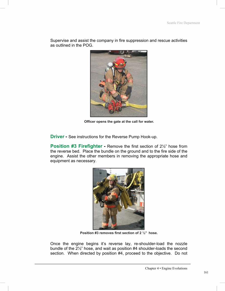
161
Seattle Fire Department
Chapter 4 • Engine Evolutions
Supervise and assist the company in fire suppression and rescue activities as outlined in the POG.
PHOTO 4.62
Driver - See instructions for the Reverse Pump Hook-up.
Position #3 Firefighter - Remove the first section of 2½” hose from
the reverse bed. Place the bundle on the ground and to the fire side of the engine. Assist the other members in removing the appropriate hose and equipment as necessary.
PHOTO 4.63
Once the engine begins it’s reverse lay, re-shoulder-load the nozzle bundle of the 2½” hose, and wait as position #4 shoulder-loads the second section. When directed by position #4, proceed to the objective. Do not
Officer opens the gate at the call for water.
Position #3 removes first section of 2 ½” hose.
Seattle Fire Department
Chapter 4 • Engine Evolutions
ENGINE COMPANY INTRODUCTION
Overview
Engine company hose evolutions will follow a department-wide standard. The goal is to provide the most efficient methods of performing fire ground operations. All members shall possess a solid understanding of the operations described within this section, as they will serve as the basis for engine company fire ground operations. These evolutions will be used to evaluate Recruit Firefighter’s during drill school and Operations Division member’s throughout their careers. In some instances, emergency situations may not be satisfactorily resolved by utilizing only these basic evolutions. The company Officer maintains the ability to alter these standard methods when necessary.
It should be noted that the Seattle Fire Department Basic Skills Manual is not a tactics textbook. The knowledge and decision-making skills must be learned and practiced using approved curriculum and methods.
Introduction
Stretching and operating hose lines is the primary function of the engine company. All members must realize the importance of the initial line stretched at a structural fire. More lives are saved at fire operations by the proper positioning and operating of hose lines than by all other life-saving techniques available to firefighting forces. The majority of structural fires are controlled and extinguished by this initial line. The first hose line is placed between the fire and any persons endangered by it. Often this is accomplished by stretching the line via the primary means of egress; usually the main entrance or stairway. The purpose of this line is to: • Allow occupants to evacuate • Allow members to proceed to the floors above the fire for search • Confine and extinguish the fire
If it is determined there is no life hazard in the building, the first line is positioned between the fire and the most severe exposure. This will likely be an internal exposure (within the fire building) in the case of an offensive fire attack or an adjacent building in the event of a defensive fire attack.
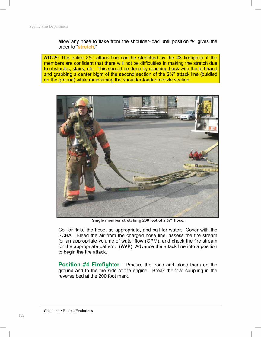
162
Seattle Fire Department
Chapter 4 • Engine Evolutions
allow any hose to flake from the shoulder-load until position #4 gives the order to “stretch.”
NOTE: The entire 2½” attack line can be stretched by the #3 firefighter if the members are confident that there will not be difficulties in making the stretch due to obstacles, stairs, etc. This should be done by reaching back with the left hand and grabbing a center bight of the second section of the 2½” attack line (buldled on the ground) while maintaining the shoulder-loaded nozzle section.
PHOTO 4.64
Coil or flake the hose, as appropriate, and call for water. Cover with the SCBA. Bleed the air from the charged hose line, assess the fire stream for an appropriate volume of water flow (GPM), and check the fire stream for the appropriate pattern. (AVP) Advance the attack line into a position to begin the fire attack.
Position #4 Firefighter - Procure the irons and place them on the
ground and to the fire side of the engine. Break the 2½” coupling in the reverse bed at the 200 foot mark.
Single member stretching 200 feet of 2 ½” hose.

163
Seattle Fire Department
Chapter 4 • Engine Evolutions
PHOTO 4.65
Remove the second section of 2½” hose from the bed and place it on the ground next to the nozzle bundle. The nozzle bundle should be positioned nearest to the fire. If the Officer is unavailable, remove the tri-gate and position it between the unloaded 2½” bundles and the engine. Foot the tri-gate and ensure that all required hose and equipment has been removed from the engine. When directed by the Officer, signal the driver to proceed to the hydrant. This signal should be both audible and visual, by pointing forward while shouting “Go ahead.”
NOTE: If the Officer is unable to foot the tri-gate or LDH because of incident command responsibilities, the position #4 firefighter will have sole responsibility of ensuring that all required hose and equipment has been removed from the engine. After completing this task, position #4 firefighter will then direct the driver to proceed to the hydrant without instructions from the Officer.
Break the 2 ½” hose at 200 feet.
Seattle Fire Department
Chapter 4 • Engine Evolutions
ENGINE COMPANY INTRODUCTION
Overview
Engine company hose evolutions will follow a department-wide standard. The goal is to provide the most efficient methods of performing fire ground operations. All members shall possess a solid understanding of the operations described within this section, as they will serve as the basis for engine company fire ground operations. These evolutions will be used to evaluate Recruit Firefighter’s during drill school and Operations Division member’s throughout their careers. In some instances, emergency situations may not be satisfactorily resolved by utilizing only these basic evolutions. The company Officer maintains the ability to alter these standard methods when necessary.
It should be noted that the Seattle Fire Department Basic Skills Manual is not a tactics textbook. The knowledge and decision-making skills must be learned and practiced using approved curriculum and methods.
Introduction
Stretching and operating hose lines is the primary function of the engine company. All members must realize the importance of the initial line stretched at a structural fire. More lives are saved at fire operations by the proper positioning and operating of hose lines than by all other life-saving techniques available to firefighting forces. The majority of structural fires are controlled and extinguished by this initial line. The first hose line is placed between the fire and any persons endangered by it. Often this is accomplished by stretching the line via the primary means of egress; usually the main entrance or stairway. The purpose of this line is to: • Allow occupants to evacuate • Allow members to proceed to the floors above the fire for search • Confine and extinguish the fire
If it is determined there is no life hazard in the building, the first line is positioned between the fire and the most severe exposure. This will likely be an internal exposure (within the fire building) in the case of an offensive fire attack or an adjacent building in the event of a defensive fire attack.

164
Seattle Fire Department
Chapter 4 • Engine Evolutions
PHOTO. 4.66
When safe to do so, connect the 2½” female coupling to the tri-gated wye. Do not open the gate valve at this time.
PHOTO 4.67 PHOTO 4.68
Shoulder-load the second section of the 2½” hose and pick up the irons. Begin to stretch the hose to the location indicated by the Officer. As you throw the last flake of hose from your shoulder, instruct the position #3 firefighter to “stretch.” Provide forcible entry as required. Cover with the SCBA at the appropriate time. Assist in advancing and operating the hose line.
Look to see that all equipment and hose has been removed.
Position #4 connecting the 2 ½” hose to the tri-gate.
Both members making the stretch.
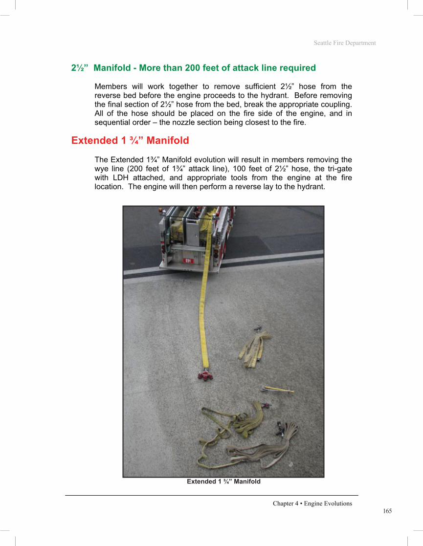
165
Seattle Fire Department
Chapter 4 • Engine Evolutions
2½” Manifold - More than 200 feet of attack line required Members will work together to remove sufficient 2½” hose from the reverse bed before the engine proceeds to the hydrant. Before removing the final section of 2½” hose from the bed, break the appropriate coupling. All of the hose should be placed on the fire side of the engine, and in sequential order – the nozzle section being closest to the fire.
Extended 1 ¾” Manifold The Extended 1¾” Manifold evolution will result in members removing the wye line (200 feet of 1¾” attack line), 100 feet of 2½” hose, the tri-gate with LDH attached, and appropriate tools from the engine at the fire location. The engine will then perform a reverse lay to the hydrant.
PHOTO 4.69
Extended 1 ¾” Manifold
Seattle Fire Department
Chapter 4 • Engine Evolutions
ENGINE COMPANY INTRODUCTION
Overview
Engine company hose evolutions will follow a department-wide standard. The goal is to provide the most efficient methods of performing fire ground operations. All members shall possess a solid understanding of the operations described within this section, as they will serve as the basis for engine company fire ground operations. These evolutions will be used to evaluate Recruit Firefighter’s during drill school and Operations Division member’s throughout their careers. In some instances, emergency situations may not be satisfactorily resolved by utilizing only these basic evolutions. The company Officer maintains the ability to alter these standard methods when necessary.
It should be noted that the Seattle Fire Department Basic Skills Manual is not a tactics textbook. The knowledge and decision-making skills must be learned and practiced using approved curriculum and methods.
Introduction
Stretching and operating hose lines is the primary function of the engine company. All members must realize the importance of the initial line stretched at a structural fire. More lives are saved at fire operations by the proper positioning and operating of hose lines than by all other life-saving techniques available to firefighting forces. The majority of structural fires are controlled and extinguished by this initial line. The first hose line is placed between the fire and any persons endangered by it. Often this is accomplished by stretching the line via the primary means of egress; usually the main entrance or stairway. The purpose of this line is to: • Allow occupants to evacuate • Allow members to proceed to the floors above the fire for search • Confine and extinguish the fire
If it is determined there is no life hazard in the building, the first line is positioned between the fire and the most severe exposure. This will likely be an internal exposure (within the fire building) in the case of an offensive fire attack or an adjacent building in the event of a defensive fire attack.

166
Seattle Fire Department
Chapter 4 • Engine Evolutions
NOTE: If more than 300 feet of hose will be needed to reach the objective from the manifold, members will work together to remove additional 2½” hose from the engine as needed. The Officer must indicate the desired length of the stretch to the company members if longer than 300 feet. Example: “Extended 1¾” Manifold – 500 feet.”
Officer - Direct the driver where to position the engine. Give verbal
directions to the crew designating the evolution to be performed, and the destination of the hose line (e.g. “Extended 1¾” Manifold to floor 2”). Remove the Officer’s SCBA and appropriate tools from the engine and place these items on the ground. Remove the tri-gated wye, with LDH attached, and position it between the unloaded hose and the engine. Ensure that all required hose and equipment for the evolution has been removed from the engine. Kneel at the tri-gate and send the engine to the hydrant. This signal should be both audible and visual, by pointing forward while shouting “Go ahead.” Foot the tri-gate until the engine is at least 150 feet away. (The removal of the tri-gate and it’s footing may be assigned to the position #4 firefighter if the Officer has command duties to attend to).
NOTE: If the Officer is unable to foot the tri-gate or LDH because of incident command responsibilities, the position #4 firefighter will have sole responsibility of ensuring that all required hose and equipment has been removed from the engine. After completing this task, position #4 firefighter will then direct the driver to proceed to the hydrant without instructions from the Officer.
Sling the SCBA to the stand-by position. Open the tri-gated wye valve at the call for water from the #3 firefighter. Supervise and assist the company in fire suppression and rescue activities as outlined in the POG.
Driver - See instructions for the Reverse Pump Hook-up.
Position #3 Firefighter - Remove each section of the 1¾” wye load
and place them on the ground and to the fire side of the engine. The nozzle section should be nearest to the fire. Remove the tri-gate and place it between the unloaded hose and the engine if this has not already been done.
NOTE: If the wye load is properly tied, it is possible to remove the entire bundle like a preconnect. If this does not seem possible, remove one section at a time, attempting to keep the individual bundles intact.

167
Seattle Fire Department
Chapter 4 • Engine Evolutions
Re-shoulder-load the nozzle bundle of the 1¾” wye load and wait as position #4 firefighter shoulder-loads the second section. When directed by the position #4 firefighter, advance to the location designated by the Officer. Do not allow any hose to flake from the shoulder-load until position #4 gives the order to “stretch.” Coil or flake the hose, as appropriate, and call for water. Cover with the SCBA. Bleed the air from the charged hose line, assess the fire stream for an appropriate volume of water flow (GPM), and check the fire stream for the appropriate pattern. (AVP) Advance the attack line into a position to begin fire attack.
Position #4 Firefighter - Procure the irons and place them on the
ground and to the fire side of the engine. Break the first coupling in the 2½” reverse bed. Remove the first 100 feet of 2½” hose and place it between the 1¾” wye bundles and the engine. Remove the tri-gate if this has not already been done. Foot the tri-gate and ensure that all required hose and equipment have been removed from the engine.
PHOTO 4.70
NOTE: If the Officer is unable to foot the tri-gate or LDH because of incident command responsibilities, the position #4 firefighter will have sole responsibility of ensuring that all required hose and equipment has been removed from the engine. After completing this task, position #4 firefighter will then direct the driver to proceed to the hydrant without instructions from the Officer.
If directed by the Officer, signal the driver to proceed to the hydrant. This signal should be both audible and visual, by pointing forward while shouting “Go ahead.”
Look to see that all equipment and hose has been removed.
Seattle Fire Department
Chapter 4 • Engine Evolutions
ENGINE COMPANY INTRODUCTION
Overview
Engine company hose evolutions will follow a department-wide standard. The goal is to provide the most efficient methods of performing fire ground operations. All members shall possess a solid understanding of the operations described within this section, as they will serve as the basis for engine company fire ground operations. These evolutions will be used to evaluate Recruit Firefighter’s during drill school and Operations Division member’s throughout their careers. In some instances, emergency situations may not be satisfactorily resolved by utilizing only these basic evolutions. The company Officer maintains the ability to alter these standard methods when necessary.
It should be noted that the Seattle Fire Department Basic Skills Manual is not a tactics textbook. The knowledge and decision-making skills must be learned and practiced using approved curriculum and methods.
Introduction
Stretching and operating hose lines is the primary function of the engine company. All members must realize the importance of the initial line stretched at a structural fire. More lives are saved at fire operations by the proper positioning and operating of hose lines than by all other life-saving techniques available to firefighting forces. The majority of structural fires are controlled and extinguished by this initial line. The first hose line is placed between the fire and any persons endangered by it. Often this is accomplished by stretching the line via the primary means of egress; usually the main entrance or stairway. The purpose of this line is to: • Allow occupants to evacuate • Allow members to proceed to the floors above the fire for search • Confine and extinguish the fire
If it is determined there is no life hazard in the building, the first line is positioned between the fire and the most severe exposure. This will likely be an internal exposure (within the fire building) in the case of an offensive fire attack or an adjacent building in the event of a defensive fire attack.

168
Seattle Fire Department
Chapter 4 • Engine Evolutions
When safe to do so, connect the 2½” female coupling to the tri-gate. Do NOT open the tri-gate valve at this time. (It will be done by the Officer after the stretch is complete.)
PHOTO 4.71
Shoulder-load the second section of the 1¾” hose, grasp the middle bight of the 2½” with the left hand and the 2½” male coupling. Begin to stretch to the location indicated by the Officer.
PHOTO 4.72
When all of the 2½” hose has been stretched out, place your section of the wye load on the ground at the end of the 2 ½” hose and untie the bundle. Remove the 2 ½” nozzle. Place the 1 ¾” wye on the 2 ½” hose. Open the appropriate quarter-turn valve on the wye. Tie the valve in an open position and begin the stretch of the 1 ¾” hose.
Connecting the 2 ½” hose to the tri-gate.
Beginning the stretch.

169
Seattle Fire Department
Chapter 4 • Engine Evolutions
If there are no obstacles, the #3 firefighter may be able to simply grab the center bight of the bundle on the ground and complete the stretch themselves (see Options for Stretching the Extended 1 ¾” Attack, in the next section). If there are obstacles (furniture, stairs, etc.), it may be necessary for the #4 firefighter to re-shoulder-load the remainder of the 1¾” hose, pick-up the irons, and continue the stretch. If this is done, instruct the position #3 firefighter to “stretch” as you throw the last flake of hose from your shoulder Provide forcible entry as required. Cover with the SCBA. Assist in advancing and operating the hose line.
Extended 1 ¾” Manifold Stretching Option
All 1¾” and a portion of 2½” hose to be used inside the fire building:
Once the connection to the tri-gate has been made, position #3 and #4 firefighters each grab two or three bights of 2½” hose bundle with the left hand. Position #3 should grasp bights closest to the 2½” male coupling, while position #4 grasps the remaining bights. As both firefighters begin advancing the hose line to the objective, position #4 will drop off flakes of 2½” hose first. When the position #4 firefighter drops the last flake, that firefighter should instruct the position #3 firefighter to “stretch 2½”. The position #3 firefighter will then begin to drop flakes of 2½” hose.
.
Connecting the gated wye to the 2 ½” hose.
Wye tied in the open position.
Seattle Fire Department
Chapter 4 • Engine Evolutions
ENGINE COMPANY INTRODUCTION
Overview
Engine company hose evolutions will follow a department-wide standard. The goal is to provide the most efficient methods of performing fire ground operations. All members shall possess a solid understanding of the operations described within this section, as they will serve as the basis for engine company fire ground operations. These evolutions will be used to evaluate Recruit Firefighter’s during drill school and Operations Division member’s throughout their careers. In some instances, emergency situations may not be satisfactorily resolved by utilizing only these basic evolutions. The company Officer maintains the ability to alter these standard methods when necessary.
It should be noted that the Seattle Fire Department Basic Skills Manual is not a tactics textbook. The knowledge and decision-making skills must be learned and practiced using approved curriculum and methods.
Introduction
Stretching and operating hose lines is the primary function of the engine company. All members must realize the importance of the initial line stretched at a structural fire. More lives are saved at fire operations by the proper positioning and operating of hose lines than by all other life-saving techniques available to firefighting forces. The majority of structural fires are controlled and extinguished by this initial line. The first hose line is placed between the fire and any persons endangered by it. Often this is accomplished by stretching the line via the primary means of egress; usually the main entrance or stairway. The purpose of this line is to: • Allow occupants to evacuate • Allow members to proceed to the floors above the fire for search • Confine and extinguish the fire
If it is determined there is no life hazard in the building, the first line is positioned between the fire and the most severe exposure. This will likely be an internal exposure (within the fire building) in the case of an offensive fire attack or an adjacent building in the event of a defensive fire attack.

170
Seattle Fire Department
Chapter 4 • Engine Evolutions
PHOTO 4.75
Once all of this 2½” hose is fully stretched out, the evolution will proceed as earlier described in the Extended 1¾” Manifold section.
1¾” Reverse Lay The 1¾” Reverse evolution results in members removing 200 feet of 1¾” attack line (wye load), 2½” hose, a hose clamp, and appropriate tools from the engine at the fire location. The engine will then lay 2½” hose to the hydrant.
PHOTO 4.76
NOTE: If more than 200 feet of attack line will be needed to reach the objective, additional 2½” hose will be removed from the engine to extend the 200 feet of 1¾” attack line. If this is the case, be certain to remove a hose clamp from the engine as well. When safe to do so, apply the hose clamp to the 2½” line. This will allow for the control of water while the additional 2½” hose is stretched.
Position #3 and #4 firefighters stretching additional 2 ½” into the building.
1 ¾” Reverse, before the lay.

171
Seattle Fire Department
Chapter 4 • Engine Evolutions
Officer - Direct the driver where to position the engine. Give verbal
directions to the crew designating the evolution to be performed, and the destination of the hose line (e.g. “1¾” Reverse to the basement”). Remove the Officer’s SCBA, a hose clamp, and appropriate tools from the engine and place these items on the ground. If necessary, assist in removing the necessary hose. Ensure that all required hose and equipment for the evolution has been removed from the engine and send the engine to the hydrant. This signal should be both audible and visual, by pointing forward while shouting “Go ahead.” Sling the SCBA to the stand-by position. While the position #3 and #4 firefighter’s are making the stretch, ensure both gated wye valves are in the closed position. At the call for water from the position #3 firefighter, open the appropriate quarter-turn valve on the wye. Tie the valve in the open position so it can not be “accidentally” closed during firefighting. Supervise and assist the company in fire suppression and rescue activities as outlined in the POG.
Driver - See instructions for the Reverse Pump Hook-up. The only
difference will be that instead of disconnecting LDH from the bed and hooking up to a discharge, the driver will break and attach 2½” hose.
Position #3 Firefighter - Remove each section of the 1¾” wye load
and place them on the ground and to the fire side of the engine. The nozzle section should be nearest to the fire.
NOTE: If the wye load is properly tied, it is possible to remove the entire bundle like a preconnect. If this does not seem possible, remove one section at a time, attempting to keep the individual bundles intact.
Give the gated wye to the position #4 firefighter so that the connection to the 2½” hose can be made. Re-shoulder-load the nozzle bundle of the wye load, and wait as position #4 shoulder-loads the second section. When directed by position #4, proceed to the objective. Do not allow any hose to flake from the shoulder-load until position #4 gives the order to “stretch.”
NOTE: The entire 1¾” wye load can be stretched by the #3 firefighter if the members are confident that there will not be difficulties in making the stretch due to obstacles, stairs, etc. This should be done by reaching back with the left hand and grabbing a center bight of the second section of the 1 ¾” wye lin e while maintaining the shoulder-loaded nozzle section.
Seattle Fire Department
Chapter 4 • Engine Evolutions
ENGINE COMPANY INTRODUCTION
Overview
Engine company hose evolutions will follow a department-wide standard. The goal is to provide the most efficient methods of performing fire ground operations. All members shall possess a solid understanding of the operations described within this section, as they will serve as the basis for engine company fire ground operations. These evolutions will be used to evaluate Recruit Firefighter’s during drill school and Operations Division member’s throughout their careers. In some instances, emergency situations may not be satisfactorily resolved by utilizing only these basic evolutions. The company Officer maintains the ability to alter these standard methods when necessary.
It should be noted that the Seattle Fire Department Basic Skills Manual is not a tactics textbook. The knowledge and decision-making skills must be learned and practiced using approved curriculum and methods.
Introduction
Stretching and operating hose lines is the primary function of the engine company. All members must realize the importance of the initial line stretched at a structural fire. More lives are saved at fire operations by the proper positioning and operating of hose lines than by all other life-saving techniques available to firefighting forces. The majority of structural fires are controlled and extinguished by this initial line. The first hose line is placed between the fire and any persons endangered by it. Often this is accomplished by stretching the line via the primary means of egress; usually the main entrance or stairway. The purpose of this line is to: • Allow occupants to evacuate • Allow members to proceed to the floors above the fire for search • Confine and extinguish the fire
If it is determined there is no life hazard in the building, the first line is positioned between the fire and the most severe exposure. This will likely be an internal exposure (within the fire building) in the case of an offensive fire attack or an adjacent building in the event of a defensive fire attack.
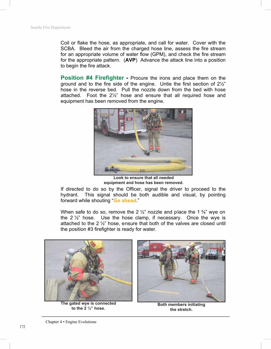
172
Seattle Fire Department
Chapter 4 • Engine Evolutions
Coil or flake the hose, as appropriate, and call for water. Cover with the SCBA. Bleed the air from the charged hose line, assess the fire stream for an appropriate volume of water flow (GPM), and check the fire stream for the appropriate pattern. (AVP) Advance the attack line into a position to begin the fire attack.
Position #4 Firefighter - Procure the irons and place them on the
ground and to the fire side of the engine. Untie the first section of 2½” hose in the reverse bed. Pull the nozzle down from the bed with hose attached. Foot the 2½” hose and ensure that all required hose and equipment has been removed from the engine.
PHOTO 4.77
If directed to do so by the Officer, signal the driver to proceed to the hydrant. This signal should be both audible and visual, by pointing forward while shouting “Go ahead.” When safe to do so, remove the 2 ½” nozzle and place the 1 ¾” wye on the 2 ½” hose. Use the hose clamp, if necessary. Once the wye is attached to the 2 ½” hose, ensure that both of the valves are closed until the position #3 firefighter is ready for water.
PHOTO 4.78 PHOTO 4.79
Look to ensure that all needed equipment and hose has been removed.
The gated wye is connected to the 2 ½” hose.
Both members initiating the stretch.

173
Seattle Fire Department
Chapter 4 • Engine Evolutions
If the position #3 firefighter requires assistance with the stretch, shoulder-load the second section of the 1¾” hose and pick up the irons. Begin to stretch to the location indicated by the Officer. As you throw the last flake of hose from your shoulder, instruct the position #3 firefighter to “stretch.” Provide forcible entry as required. Cover with the SCBA at the appropriate time. Assist in advancing and operating the hose line.
2½” Reverse Lay The 2½” Reverse evolution results in members removing 200 feet of 2½” attack line (leaving the hose attached to the 2½” reverse bed), a hose clamp, and appropriate tools from the engine at the fire location. The engine will then lay 2½” hose to the hydrant.
PHOTO 4.80
NOTE: If more than 200 feet of attack line will be needed to reach the objective, additional 2½” hose will be removed from the engine to extend the line. The Officer must indicate the desired length of the stretch to the company members if longer than 200 feet. Example: “2½” Reverse – 400 feet.”
Officer - Direct the driver where to position the engine. Give verbal
directions to the crew designating the evolution to be performed, and the destination of the hose line (e.g. “2½” Reverse to the loading dock”). Remove the Officer’s SCBA and appropriate tools from the engine and place these items on the ground. If necessary, assist in removing the required hose from the engine. Ensure that all required hose and equipment for the evolution has been removed from the engine. Foot the 2½” hose and send the engine to the hydrant. This signal should be both audible and visual, by pointing forward while shouting “Go ahead.”
2 ½” Reverse, before the lay.
Seattle Fire Department
Chapter 4 • Engine Evolutions
ENGINE COMPANY INTRODUCTION
Overview
Engine company hose evolutions will follow a department-wide standard. The goal is to provide the most efficient methods of performing fire ground operations. All members shall possess a solid understanding of the operations described within this section, as they will serve as the basis for engine company fire ground operations. These evolutions will be used to evaluate Recruit Firefighter’s during drill school and Operations Division member’s throughout their careers. In some instances, emergency situations may not be satisfactorily resolved by utilizing only these basic evolutions. The company Officer maintains the ability to alter these standard methods when necessary.
It should be noted that the Seattle Fire Department Basic Skills Manual is not a tactics textbook. The knowledge and decision-making skills must be learned and practiced using approved curriculum and methods.
Introduction
Stretching and operating hose lines is the primary function of the engine company. All members must realize the importance of the initial line stretched at a structural fire. More lives are saved at fire operations by the proper positioning and operating of hose lines than by all other life-saving techniques available to firefighting forces. The majority of structural fires are controlled and extinguished by this initial line. The first hose line is placed between the fire and any persons endangered by it. Often this is accomplished by stretching the line via the primary means of egress; usually the main entrance or stairway. The purpose of this line is to: • Allow occupants to evacuate • Allow members to proceed to the floors above the fire for search • Confine and extinguish the fire
If it is determined there is no life hazard in the building, the first line is positioned between the fire and the most severe exposure. This will likely be an internal exposure (within the fire building) in the case of an offensive fire attack or an adjacent building in the event of a defensive fire attack.

174
Seattle Fire Department
Chapter 4 • Engine Evolutions
Sling the SCBA to the stand-by position. Open the hose clamp at the call for water from the position #3 firefighter. Supervise and assist the company in fire suppression and rescue activities as outlined in the POG.
Driver - Follow the instructions for the 1¾” Reverse evolution.
Position #3 Firefighter - Remove the first section of the 2½” hose
from the reverse bed and place it on the ground to the fire side. Once the reverse lay has been made, re-shoulder-load the nozzle section of the 2½” hose. When directed by position #4, proceed to the objective. Do not allow any hose to flake from the shoulder-load until position #4 gives the order to “stretch.” Coil or flake the hose, as appropriate, and call for water. Cover with the SCBA. Bleed the air from the charged hose line, assess the fire stream for an appropriate volume of water flow (GPM), and check the fire stream for the appropriate pattern. (AVP) Advance the attack line into a position to begin the fire attack.
Position #4 Firefighter - Procure the irons and place them on the
ground and to the fire side of the engine. Remove the second section of the 2½” hose from the reverse bed (keep the hose attached) and place it next to the nozzle section of 2½” hose. When directed by the Officer, foot the 2½” hose and signal the driver to proceed to the hydrant. This signal should be both audible and visual, by pointing forward while shouting “Go ahead.”
NOTE: If the Officer is unable to foot the 2 ½” hose because of incident command responsibilities, the position #4 firefighter will have sole responsibility of ensuring that all required hose and equipment has been removed from the engine. After completing this task, position #4 firefighter will then direct the driver to proceed to the hydrant without instructions from the Officer.
When safe to do so, apply the hose clamp on the 2½” hose. Ensure clamp is not applied within 3 feet of a coupling.
Shoulder-load the second section of the 2½” and pick up the irons. Begin stretching to the location indicated by the Officer with the position #3 firefighter. As you throw the last flake of hose from your shoulder, instruct the position #3 firefighter to “stretch.” Provide forcible entry as required. Cover with the SCBA at the appropriate time. Assist in advancing and operating the hose line.

175
Seattle Fire Department
Chapter 4 • Engine Evolutions
Monitor Manifold The Monitor Manifold evolution will begin with 200 feet of 2½” hose, 200 feet of 1¾” hose, the tri-gate with LDH attached, a portable monitor appliance with base, and appropriate tools being removed from the engine at the fire location. The engine will then perform a Reverse Lay to the hydrant.
PHOTO 4.81 PHOTO 4.82
NOTE: If the monitor will be put into operation in a location away from where the engine was able to stop, ensure sufficient LDH is removed from the engine prior to the reverse lay begins.
Officer - Direct the driver where to position the engine. Give verbal
directions to the crew designating the evolution to be performed, and the destination of the hose line (e.g. “Monitor Manifold on the Alpha side of the warehouse”). Remove the Officer’s SCBA and appropriate tools from the engine and place these items on the ground. Receive the monitor and the monitor base from the position #3 firefighter if these items are kept in a compartment on top of the engine. Attach the monitor to the base and position it at the desired place of operation. Remove the tri-gated wye, with LDH attached, and position it between the unloaded hose and the engine. Ensure that all required hose and equipment for the evolution has been removed from the engine.
Monitor Manifold, before the lay. Charged Monitor Manifold.
Seattle Fire Department
Chapter 4 • Engine Evolutions
ENGINE COMPANY INTRODUCTION
Overview
Engine company hose evolutions will follow a department-wide standard. The goal is to provide the most efficient methods of performing fire ground operations. All members shall possess a solid understanding of the operations described within this section, as they will serve as the basis for engine company fire ground operations. These evolutions will be used to evaluate Recruit Firefighter’s during drill school and Operations Division member’s throughout their careers. In some instances, emergency situations may not be satisfactorily resolved by utilizing only these basic evolutions. The company Officer maintains the ability to alter these standard methods when necessary.
It should be noted that the Seattle Fire Department Basic Skills Manual is not a tactics textbook. The knowledge and decision-making skills must be learned and practiced using approved curriculum and methods.
Introduction
Stretching and operating hose lines is the primary function of the engine company. All members must realize the importance of the initial line stretched at a structural fire. More lives are saved at fire operations by the proper positioning and operating of hose lines than by all other life-saving techniques available to firefighting forces. The majority of structural fires are controlled and extinguished by this initial line. The first hose line is placed between the fire and any persons endangered by it. Often this is accomplished by stretching the line via the primary means of egress; usually the main entrance or stairway. The purpose of this line is to: • Allow occupants to evacuate • Allow members to proceed to the floors above the fire for search • Confine and extinguish the fire
If it is determined there is no life hazard in the building, the first line is positioned between the fire and the most severe exposure. This will likely be an internal exposure (within the fire building) in the case of an offensive fire attack or an adjacent building in the event of a defensive fire attack.

176
Seattle Fire Department
Chapter 4 • Engine Evolutions
Kneel at the tri-gate and send the engine to the hydrant. This signal should be both audible and visual, by pointing forward while shouting “Go ahead.” Foot the tri-gate until the engine is at least 150 feet away. (The removal of the tri-gate and it’s footing may be assigned to the position #4 firefighter if the Officer has command duties to attend to.)
PHOTO 4.83
Ensure all three tri-gate valves are closed. Sling the SCBA to the stand-by position. Communicate to the driver which monitor tip is in use so the driver can correctly account for friction loss in the hose lay. Direct the monitor operation.
Driver - Position the engine where the Officer instructs. Honk the
engine’s horn once to signal to the members that it is safe to exit the cab. Set the parking brake. Exit the engine and set the wheel blocks. Remove both sections of the 1¾” wye load and place them to the non-fire side of the engine.
NOTE: If the wye load is properly tied, it is possible to remove the entire bundle like a preconnect. If this does not seem possible, remove one section at a time, attempting to keep the individual bundles intact.
The nozzle section should be nearest to the fire. Remove the wheel blocks and return to the driver’s seat. Prepare to initiate the reverse lay upon receiving direction from the Officer or position #4 firefighter. Once at the hydrant, spot the engine to perform a Reverse Pump Hook-up using the soft suction. See instructions for the reverse pump hookup.
Position #3 Firefighter - Procure the monitor and it’s base from the
engine. If it is located in a compartment on top of the hose bed, pass this equipment to the Officer. Assist the #4 firefighter in removing 2½” hose from the reverse bed or removing the wye line, as needed.
Look to ensure that all needed equipment and hose has been removed.

177
Seattle Fire Department
Chapter 4 • Engine Evolutions
When all hose and equipment has been removed from the engine, break the 200 feet of 2½” hose into two separate sections. Hand the female couplings off to the position #4 firefighter at the tri-gate. With a male coupling in each hand, simultaneously stretch the 2½” hose lines approximately 50 feet beyond the monitor (one hose on each side of the appliance).
PHOTO 4.84
With the couplings still in hand, turn to face the monitor. Proceed back to a point approximately 20 feet behind the monitor.
PHOTO 4.85
Both 2 ½” lines are stretched 50 feet beyond the monitor.
Lines are brought back 20 feet behind the monitor.
Seattle Fire Department
Chapter 4 • Engine Evolutions
ENGINE COMPANY INTRODUCTION
Overview
Engine company hose evolutions will follow a department-wide standard. The goal is to provide the most efficient methods of performing fire ground operations. All members shall possess a solid understanding of the operations described within this section, as they will serve as the basis for engine company fire ground operations. These evolutions will be used to evaluate Recruit Firefighter’s during drill school and Operations Division member’s throughout their careers. In some instances, emergency situations may not be satisfactorily resolved by utilizing only these basic evolutions. The company Officer maintains the ability to alter these standard methods when necessary.
It should be noted that the Seattle Fire Department Basic Skills Manual is not a tactics textbook. The knowledge and decision-making skills must be learned and practiced using approved curriculum and methods.
Introduction
Stretching and operating hose lines is the primary function of the engine company. All members must realize the importance of the initial line stretched at a structural fire. More lives are saved at fire operations by the proper positioning and operating of hose lines than by all other life-saving techniques available to firefighting forces. The majority of structural fires are controlled and extinguished by this initial line. The first hose line is placed between the fire and any persons endangered by it. Often this is accomplished by stretching the line via the primary means of egress; usually the main entrance or stairway. The purpose of this line is to: • Allow occupants to evacuate • Allow members to proceed to the floors above the fire for search • Confine and extinguish the fire
If it is determined there is no life hazard in the building, the first line is positioned between the fire and the most severe exposure. This will likely be an internal exposure (within the fire building) in the case of an offensive fire attack or an adjacent building in the event of a defensive fire attack.

178
Seattle Fire Department
Chapter 4 • Engine Evolutions
Turn again towards the monitor, while still holding each coupling, and connect each of the 2½” lines to the monitor.
PHOTO 4.86
Spread out the 2½” hose lines into position for monitor operation. Secure the monitor’s anchor chain to the 2½” hose lines at the point where they cross in front of the monitor. Tie a body loop around the 2½” hose lines at the point where they cross behind the monitor.
PHOTO 4.87
Connections to the monitor are made.
The monitor is ready for operation.

179
Seattle Fire Department
Chapter 4 • Engine Evolutions
Position #4 Firefighter - Procure the irons and place them on the
ground and to the fire side of the engine. Remove the first section of 2½” hose from the reverse bed and place it on the fire side of the engine. Break the 2½” at the 200 foot mark and remove the second section, placing it on the ground next to the first. If not yet done by the Officer, remove the tri-gate and position it between the unloaded hose and the engine. If directed by the Officer, foot the tri-gate and signal the driver to proceed to the hydrant. This signal should be both audible and visual, by pointing forward while shouting “Go ahead.”
NOTE: If the Officer is unable to foot the tri-gate or LDH because of incident command responsibilities, the position #4 firefighter will have sole responsibility of ensuring that all required hose and equipment has been removed from the engine. After completing this task, position #4 firefighter will then direct the driver to proceed to the hydrant without instructions from the Officer.
When safe to do so, connect both 2½” female couplings to the tri-gate. Once the position #3 firefighter has completely positioned the 2½” hose, assist the position #3 firefighter in securing the monitor for safe operation. Select proper tip size, as directed by the Officer. Open the appropriate tri-gate valves at the call for water. Direct the operation of the monitor if the Officer is not present.
PHOTO 4.88
Finished Monitor Manifold.
Seattle Fire Department
Chapter 4 • Engine Evolutions
ENGINE COMPANY INTRODUCTION
Overview
Engine company hose evolutions will follow a department-wide standard. The goal is to provide the most efficient methods of performing fire ground operations. All members shall possess a solid understanding of the operations described within this section, as they will serve as the basis for engine company fire ground operations. These evolutions will be used to evaluate Recruit Firefighter’s during drill school and Operations Division member’s throughout their careers. In some instances, emergency situations may not be satisfactorily resolved by utilizing only these basic evolutions. The company Officer maintains the ability to alter these standard methods when necessary.
It should be noted that the Seattle Fire Department Basic Skills Manual is not a tactics textbook. The knowledge and decision-making skills must be learned and practiced using approved curriculum and methods.
Introduction
Stretching and operating hose lines is the primary function of the engine company. All members must realize the importance of the initial line stretched at a structural fire. More lives are saved at fire operations by the proper positioning and operating of hose lines than by all other life-saving techniques available to firefighting forces. The majority of structural fires are controlled and extinguished by this initial line. The first hose line is placed between the fire and any persons endangered by it. Often this is accomplished by stretching the line via the primary means of egress; usually the main entrance or stairway. The purpose of this line is to: • Allow occupants to evacuate • Allow members to proceed to the floors above the fire for search • Confine and extinguish the fire
If it is determined there is no life hazard in the building, the first line is positioned between the fire and the most severe exposure. This will likely be an internal exposure (within the fire building) in the case of an offensive fire attack or an adjacent building in the event of a defensive fire attack.

180
Seattle Fire Department
Chapter 4 • Engine Evolutions
Standpipe Manifold
The Standpipe Manifold evolution will result in members removing 200 feet of 1¾” attack line (wye load or a high rise bundle), 200 feet of 2 ½” hose for connection to the standpipe, the tri-gate with LDH attached, and appropriate tools from the engine at the fire location. The engine will then perform a reverse lay to the hydrant.
NOTES: If more than 200 feet of attack line will be needed to reach the objective from the standpipe outlet, or if 2-1/2” hose will be used as the attack line, members will work together to remove additional 2-1/2” hose from the reverse bed as needed.
If the distance from the tailboard to the standpipe is more than 100 feet, remove additional LDH from the engine before it leaves the scene to ensure reaching the standpipe.
Officer - Direct the driver where to position the engine (near the
standpipe). Give verbal directions to the crew designating the evolution to be performed, and the destination of the hose line (e.g. “Standpipe Manifold, 1¾” line to floor 10”). Remove the Officer’s SCBA and appropriate tools from the engine and place these items on the ground. Assist in removing the required hose from the engine. Ensure that all required hose and equipment for the evolution has been removed from the engine. Kneel at the tri-gate and
Standpipe Manifold, before the lay.
Charged Standpipe Manifold.

181
Seattle Fire Department
Chapter 4 • Engine Evolutions
send the engine to the hydrant. Foot the tri-gate until the engine is at least 150 feet away. (The removal of the tri-gate and it’s footing may be assigned to the position #4 firefighter if the Officer has command duties to attend to.)
NOTE: Be aware that the tri-gate may violently move if a coupling is snagged in the hose bed, or on another obstacle, during the lay. Connections to the tri-gate during the lay should be done cautiously.
Sling the SCBA to the stand-by position. Assume command responsibilities.
Driver - See instructions for the Reverse Pump Hook-up using the soft
suction.
Position #3 Firefighter - Remove each section of the 1¾” wye load
and place them on the ground and to the fire side of the engine. The nozzle section should be nearest to the fire. Assist the position #4 firefighter in removing 2½” hose from the reverse bed as needed.
NOTE: If the wye load is properly tied, it is possible to remove the entire bundle like a preconnect. If this does not seem possible, remove one section at a time, attempting to keep the individual bundles intact.
When all hose and equipment has been removed from the engine, break the 200 feet of 2½” hose into two separate sections. Hand the female couplings off to the position #4 firefighter at the tri-gate.
PHOTO 4.91 PHOTO 4.92
Passing off the 2 ½” couplings to position #4. Connecting the 2 ½” hose lines to the FDC.
Seattle Fire Department
Chapter 4 • Engine Evolutions
ENGINE COMPANY INTRODUCTION
Overview
Engine company hose evolutions will follow a department-wide standard. The goal is to provide the most efficient methods of performing fire ground operations. All members shall possess a solid understanding of the operations described within this section, as they will serve as the basis for engine company fire ground operations. These evolutions will be used to evaluate Recruit Firefighter’s during drill school and Operations Division member’s throughout their careers. In some instances, emergency situations may not be satisfactorily resolved by utilizing only these basic evolutions. The company Officer maintains the ability to alter these standard methods when necessary.
It should be noted that the Seattle Fire Department Basic Skills Manual is not a tactics textbook. The knowledge and decision-making skills must be learned and practiced using approved curriculum and methods.
Introduction
Stretching and operating hose lines is the primary function of the engine company. All members must realize the importance of the initial line stretched at a structural fire. More lives are saved at fire operations by the proper positioning and operating of hose lines than by all other life-saving techniques available to firefighting forces. The majority of structural fires are controlled and extinguished by this initial line. The first hose line is placed between the fire and any persons endangered by it. Often this is accomplished by stretching the line via the primary means of egress; usually the main entrance or stairway. The purpose of this line is to: • Allow occupants to evacuate • Allow members to proceed to the floors above the fire for search • Confine and extinguish the fire
If it is determined there is no life hazard in the building, the first line is positioned between the fire and the most severe exposure. This will likely be an internal exposure (within the fire building) in the case of an offensive fire attack or an adjacent building in the event of a defensive fire attack.

182
Seattle Fire Department
Chapter 4 • Engine Evolutions
Stretch each of the male couplings to the building’s Fire Department Connection (FDC) that feeds standpipe system. Connect the two 2½” lines to the FDC. When this is complete, stretch out any remaining 2½” hose so that no kinks are present when the lines are charged. Re-shoulder-load the nozzle section of the wye load and wait as the position #4 firefighter shoulder-loads the second section. When directed by the position #4 firefighter, proceed to the floor below the fire. Pause at this location while the position #4 firefighter connects the gated wye to the standpipe outlet. Continue up the stairs at the direction of the position #4 firefighter. Do not allow any hose to flake from the shoulder-load until position #4 gives the order to “stretch.” Coil or flake the hose, as appropriate, and call for water.
NOTE: If the stairway door on the fire floor is intact, hose may be stretched dry up the stairs above the fire floor prior to charging the hose. This will facilitate the forward progress of the charged line in the initial stages of the hose advancement.
Cover with the SCBA. Bleed the air from the charged hose line, assess the fire stream for an appropriate volume of water flow (GPM), and check the fire stream for the appropriate pattern. (AVP) Advance the attack line into a position to begin the fire attack.
Position #4 Firefighter - Procure the irons and place them on the
ground and to the fire side of the engine. Remove the first section of 2½” hose from the reverse bed and place it on the fire side of the engine. Break the 2½” at the 200 foot mark and remove the second section, placing it on the ground next to the first. Remove the tri-gate and position it between the unloaded hose and the engine. If directed by the Officer, foot the tri-gate and ensure that all required hose and equipment have been removed from the engine. If the Officer directs you to, signal the driver to proceed to the hydrant. This signal should be both audible and visual, by pointing forward while shouting “Go ahead.”
When safe to do so, connect both 2½” female couplings to the tri-gate. When the connections to the building’s FDC have been made by the position #3 firefighter, open the appropriate tri-gate gates.
Shoulder-load the second section of the 1¾” hose and pick up the irons. Proceed with the position #3 firefighter to the floor below the fire. Check to ensure that the standpipe valves on the lower floors are closed as you proceed.

183
Seattle Fire Department
Chapter 4 • Engine Evolutions
Upon reaching the floor below the fire, leave one flake at the standpipe connection and begin the stretch of the 1¾” wye line. Instruct the position #3 firefighter to “stretch” when the last flake of your hose leaves your shoulder. Once all of the 1¾” wye line has been stretched and the position #3 firefighter is ready for water, return to the standpipe connection, connect the 1¾” wye, open the standpipe valve, and open the appropriate quarter-turn valve on the wye at the call for water from the position #3 firefighter. Return to the nozzle and provide forcible entry as required. Cover with the SCBA. Assist in advancing and operating the hose line.
PHOTO 4.93
Position #4 connects to the standpipe.
Seattle Fire Department
Chapter 4 • Engine Evolutions
ENGINE COMPANY INTRODUCTION
Overview
Engine company hose evolutions will follow a department-wide standard. The goal is to provide the most efficient methods of performing fire ground operations. All members shall possess a solid understanding of the operations described within this section, as they will serve as the basis for engine company fire ground operations. These evolutions will be used to evaluate Recruit Firefighter’s during drill school and Operations Division member’s throughout their careers. In some instances, emergency situations may not be satisfactorily resolved by utilizing only these basic evolutions. The company Officer maintains the ability to alter these standard methods when necessary.
It should be noted that the Seattle Fire Department Basic Skills Manual is not a tactics textbook. The knowledge and decision-making skills must be learned and practiced using approved curriculum and methods.
Introduction
Stretching and operating hose lines is the primary function of the engine company. All members must realize the importance of the initial line stretched at a structural fire. More lives are saved at fire operations by the proper positioning and operating of hose lines than by all other life-saving techniques available to firefighting forces. The majority of structural fires are controlled and extinguished by this initial line. The first hose line is placed between the fire and any persons endangered by it. Often this is accomplished by stretching the line via the primary means of egress; usually the main entrance or stairway. The purpose of this line is to: • Allow occupants to evacuate • Allow members to proceed to the floors above the fire for search • Confine and extinguish the fire
If it is determined there is no life hazard in the building, the first line is positioned between the fire and the most severe exposure. This will likely be an internal exposure (within the fire building) in the case of an offensive fire attack or an adjacent building in the event of a defensive fire attack.
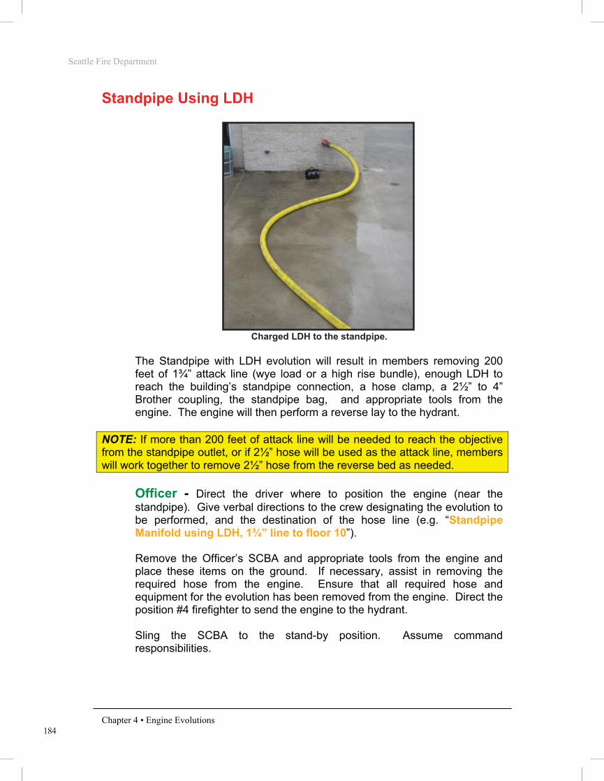
184
Seattle Fire Department
Chapter 4 • Engine Evolutions
Standpipe Using LDH
PHOTO 4.94
The Standpipe with LDH evolution will result in members removing 200 feet of 1¾” attack line (wye load or a high rise bundle), enough LDH to reach the building’s standpipe connection, a hose clamp, a 2½” to 4” Brother coupling, the standpipe bag, and appropriate tools from the engine. The engine will then perform a reverse lay to the hydrant.
NOTE: If more than 200 feet of attack line will be needed to reach the objective from the standpipe outlet, or if 2½” hose will be used as the attack line, members will work together to remove 2½” hose from the reverse bed as needed.
Officer - Direct the driver where to position the engine (near the
standpipe). Give verbal directions to the crew designating the evolution to be performed, and the destination of the hose line (e.g. “Standpipe Manifold using LDH, 1¾” line to floor 10”). Remove the Officer’s SCBA and appropriate tools from the engine and place these items on the ground. If necessary, assist in removing the required hose from the engine. Ensure that all required hose and equipment for the evolution has been removed from the engine. Direct the position #4 firefighter to send the engine to the hydrant. Sling the SCBA to the stand-by position. Assume command responsibilities.
Charged LDH to the standpipe.

185
Seattle Fire Department
Chapter 4 • Engine Evolutions
Driver - See instructions for the Reverse Pump Hook-up using the soft
suction.
Position #3 Firefighter - Remove each section of the 1¾” wye load
and place them on the ground and to the fire side of the engine. The nozzle section should be nearest to the fire building.
NOTE: If the wye load is properly tied, it is possible to remove the entire bundle like a preconnect. If this does not seem possible, remove one section at a time, attempting to keep the individual bundles intact.
Procure the 2½” to 4” Brother coupling from the position #4 firefighter and overhaul the LDH to the building’s Fire Department Connection (FDC) for the standpipe system. If the FDC has plugs, remove all plugs before charging the standpipe. This ensures that, if there are leaky clapper valves, air/water pressure will not prevent removing the remaining plugs when a second standpipe supply connection is required. If the clapper valves are faulty and water comes out under pressure, replace the plugs and recharge the standpipe. Make the connection utilizing the Brother coupling.
PHOTO 4.95 PHOTO 4.96
PHOTO 4.97
Standpipe connection with plugs. Sprinkler connection showing breakable disks.
Taking the standpipe with LDH requires the Brother coupling.
Seattle Fire Department
Chapter 4 • Engine Evolutions
ENGINE COMPANY INTRODUCTION
Overview
Engine company hose evolutions will follow a department-wide standard. The goal is to provide the most efficient methods of performing fire ground operations. All members shall possess a solid understanding of the operations described within this section, as they will serve as the basis for engine company fire ground operations. These evolutions will be used to evaluate Recruit Firefighter’s during drill school and Operations Division member’s throughout their careers. In some instances, emergency situations may not be satisfactorily resolved by utilizing only these basic evolutions. The company Officer maintains the ability to alter these standard methods when necessary.
It should be noted that the Seattle Fire Department Basic Skills Manual is not a tactics textbook. The knowledge and decision-making skills must be learned and practiced using approved curriculum and methods.
Introduction
Stretching and operating hose lines is the primary function of the engine company. All members must realize the importance of the initial line stretched at a structural fire. More lives are saved at fire operations by the proper positioning and operating of hose lines than by all other life-saving techniques available to firefighting forces. The majority of structural fires are controlled and extinguished by this initial line. The first hose line is placed between the fire and any persons endangered by it. Often this is accomplished by stretching the line via the primary means of egress; usually the main entrance or stairway. The purpose of this line is to: • Allow occupants to evacuate • Allow members to proceed to the floors above the fire for search • Confine and extinguish the fire
If it is determined there is no life hazard in the building, the first line is positioned between the fire and the most severe exposure. This will likely be an internal exposure (within the fire building) in the case of an offensive fire attack or an adjacent building in the event of a defensive fire attack.

186
Seattle Fire Department
Chapter 4 • Engine Evolutions
Return to the 1¾” wye load and re-shoulder-load the nozzle bundle. Wait as position #4 shoulder-loads the second section. When directed by position #4, proceed to the floor below the fire. Continue up the stairs at the direction of the position #4 firefighter. Do not allow any hose to flake from the shoulder-load until position #4 gives the order to “stretch.” Coil or flake the hose, as appropriate, and call for water. Cover with the SCBA. Bleed the air from the charged hose line, assess the fire stream for an appropriate volume of water flow (GPM), and check the fire stream for the appropriate pattern. (AVP) Advance the attack line into a position to begin the fire attack.
Position #4 Firefighter - Procure the irons and place them on the
ground and to the fire side of the engine. Procure the 2½” to 4” Brother coupling and a hose clamp. Hand the coupling off to the position #3 firefighter and position the hose clamp to the rear of the engine. Remove enough LDH from the engine to reach the building’s Fire Department Connection (FDC) for the standpipe system. Foot the LDH (on the engine side of the excess LDH) and ensure that all required hose and equipment have been removed from the engine.
PHOTO 4.98
When directed by the Officer, signal the driver to proceed to the hydrant. This signal should be both audible and visual, by pointing forward while shouting “Go ahead.”
Footing the LDH ahead of the portion needed to reach the FDC.

187
Seattle Fire Department
Chapter 4 • Engine Evolutions
When safe to do so, apply the hose clamp to the LDH. Once the position #3 firefighter has completed the connection to the building’s FDC, remove the clamp. Shoulder-load the second section of the 1¾” hose and pick up the irons. Proceed with the position #3 firefighter to the floor below the fire. Check to ensure that the standpipe valves on the lower floors are closed as you proceed. Upon reaching the floor below the fire, leave one flake at the standpipe connection and begin the stretch of the 1¾” wye line.
Instruct the position #3 firefighter to “stretch” when the last flake of your hose leaves your shoulder. Once all of the 1¾” wye line has been stretched and the position #3 firefighter is ready for water, return to the standpipe connection, connect the 1¾” wye, open the standpipe valve, and open the appropriate quarter-turn valve on the wye at the call for water from the position #3 firefighter. Return to the nozzle and provide forcible entry as required. Cover with the SCBA. Assist in advancing and operating the hose line.
REVERSE LAY SUPPLY LINES
Reverse Pump Hook-up Using the Soft Suction
Driver - Position the engine at the fire location as directed by the
company Officer. Honk the horn a single time, indicating that it is safe for the members to exit the cab. Remain seated in the engine while all other members remove the necessary hose and equipment. Watch for the signal to proceed to the hydrant. The Officer or the position #4 firefighter will give this order. When signaled to do so, drive to the hydrant making the reverse lay. After positioning the engine properly at the hydrant, the driver performs the in-cab pump procedures and exits the cab and sets the wheel chocks.
NOTE: When positioning the engine at the hydrant, consider which soft suction intake will be utilized and the length of the soft suction hose. (Standard soft suction length is 24 feet.) Position the intake as follows:
- Not less than one-third the length of the suction hose laterally - Not more than two-thirds forward (or short) of the hydrant
Grasp the LDH where it comes down from the hose bed. Overhaul the hose at a slight angle until the next coupling drops to the ground. Return to that coupling, break the connection, and place the female end under the tailboard for safety. Connect the male end of the LDH to the 4” rear discharge port.
Seattle Fire Department
Chapter 4 • Engine Evolutions
ENGINE COMPANY INTRODUCTION
Overview
Engine company hose evolutions will follow a department-wide standard. The goal is to provide the most efficient methods of performing fire ground operations. All members shall possess a solid understanding of the operations described within this section, as they will serve as the basis for engine company fire ground operations. These evolutions will be used to evaluate Recruit Firefighter’s during drill school and Operations Division member’s throughout their careers. In some instances, emergency situations may not be satisfactorily resolved by utilizing only these basic evolutions. The company Officer maintains the ability to alter these standard methods when necessary.
It should be noted that the Seattle Fire Department Basic Skills Manual is not a tactics textbook. The knowledge and decision-making skills must be learned and practiced using approved curriculum and methods.
Introduction
Stretching and operating hose lines is the primary function of the engine company. All members must realize the importance of the initial line stretched at a structural fire. More lives are saved at fire operations by the proper positioning and operating of hose lines than by all other life-saving techniques available to firefighting forces. The majority of structural fires are controlled and extinguished by this initial line. The first hose line is placed between the fire and any persons endangered by it. Often this is accomplished by stretching the line via the primary means of egress; usually the main entrance or stairway. The purpose of this line is to: • Allow occupants to evacuate • Allow members to proceed to the floors above the fire for search • Confine and extinguish the fire
If it is determined there is no life hazard in the building, the first line is positioned between the fire and the most severe exposure. This will likely be an internal exposure (within the fire building) in the case of an offensive fire attack or an adjacent building in the event of a defensive fire attack.

188
Seattle Fire Department
Chapter 4 • Engine Evolutions
Go to the pump panel and open the rear discharge port.
Deploy the soft suction hose and connect to the side intake, if it is not already connected. Open the intake valve fully. Proceed to the hydrant with the hydrant bag, the hydrant wrenches and the hydrant coupling of the soft suction hose.
Connecting the LDH to the 4” rear discharge port.
Opening the rear discharge valve.

189
Seattle Fire Department
Chapter 4 • Engine Evolutions
PHOTO 4.102 PHOTO 4.103
Remove engine port and a 2½” port (away from the fire) using the Corey wrench. Attach the soft suction hose and a hydrant gate. Ensure that the gate is in the closed position. Step behind the hydrant and open it fully using the Galvin wrench.
Return to the engine’s pump panel. While returning to the panel remove any significant kinks immediately. If kinks are present but it remains evident that sufficient water is entering the intake and being discharged to the tri-gate, disregard them at this time. Such kinks will be addressed at a later point. Using the throttle, increase the discharge pressure until the desired operating pressure is reached. To set your discharge pressure relief valve (PRV), you must turn the PRV operating handle counter-clockwise until the valve opens. This will be known by 3 indicators: the engine RPM’s will begin to drop, the indicated discharge pressure will also drop, and the PRV indicator light will illuminate. Once these occur, turn the operating handle the other direction (clockwise) one-half turn. Pause, and then turn the handle clockwise an additional one-half turn. Continue this procedure until the discharge pressure returns to the desired setting and the PRV indicator light turns off. Position traffic cones to protect personnel, the engine, and hose lines from approaching vehicles. While placing the cones, remove any remaining kinks in the supply line. Obtain a second water supply. Once a second supply has been established, ensure remaining equipment and hose loads are ready for use. Monitor the pump panel and the radio for further instructions.
Going to the hydrant with a hydrant bag, wrenches, and the soft suction.
Open the Hydrant Fully.
Seattle Fire Department
Chapter 4 • Engine Evolutions
ENGINE COMPANY INTRODUCTION
Overview
Engine company hose evolutions will follow a department-wide standard. The goal is to provide the most efficient methods of performing fire ground operations. All members shall possess a solid understanding of the operations described within this section, as they will serve as the basis for engine company fire ground operations. These evolutions will be used to evaluate Recruit Firefighter’s during drill school and Operations Division member’s throughout their careers. In some instances, emergency situations may not be satisfactorily resolved by utilizing only these basic evolutions. The company Officer maintains the ability to alter these standard methods when necessary.
It should be noted that the Seattle Fire Department Basic Skills Manual is not a tactics textbook. The knowledge and decision-making skills must be learned and practiced using approved curriculum and methods.
Introduction
Stretching and operating hose lines is the primary function of the engine company. All members must realize the importance of the initial line stretched at a structural fire. More lives are saved at fire operations by the proper positioning and operating of hose lines than by all other life-saving techniques available to firefighting forces. The majority of structural fires are controlled and extinguished by this initial line. The first hose line is placed between the fire and any persons endangered by it. Often this is accomplished by stretching the line via the primary means of egress; usually the main entrance or stairway. The purpose of this line is to: • Allow occupants to evacuate • Allow members to proceed to the floors above the fire for search • Confine and extinguish the fire
If it is determined there is no life hazard in the building, the first line is positioned between the fire and the most severe exposure. This will likely be an internal exposure (within the fire building) in the case of an offensive fire attack or an adjacent building in the event of a defensive fire attack.

190
Seattle Fire Department
Chapter 4 • Engine Evolutions
If two members are available - The pump and hydrant operations
for two members are the same as those for the driver (alone), except that a hydrant member (the driver of the second-in engine or another assigned member) removes the hydrant wrenches and hydrant bag and makes the soft suction connection to the hydrant. Meanwhile, the driver will perform the necessary pump panel procedures. After the hydrant is opened, the member will assist the driver, if necessary, and then dons an SCBA and follows the lines to the fire operation, removing all kinks while proceeding. The hydrant member shall then report to the Officer for further assignment.
PHOTO 4.104
Second Supply for a Reverse Pump Hook-up To obtain a second supply for a reverse pump hook up, move to the rear of the engine and remove the female coupling of the LDH from under the tailboard. Overhaul the LDH to the rear of the engine until the next coupling drops to the ground. Proceed to the hydrant with female coupling. Leave the female coupling at the hydrant and return to the tailboard. Once at the tailboard, break the LDH coupling, and place the female end under the tailboard to minimize the tripping hazard. Connect the male end of the LDH to the unused side pump intake using a 4” double female. Do NOT open the intake valve until the hydrant connection is made. Return to the hydrant and attach the female end of the LDH to the hydrant gate. Open the gate fully. Move back to the pump panel, removing all kinks in the hose as you proceed. Once at the panel, open the intake valve fully.
Hydrant member makes supply connections and opens the hydrant.

191
Seattle Fire Department
Chapter 4 • Engine Evolutions
Supply Options for a Reverse Pump Hook-up Using LDH instead of the Soft Suction (Preferred option)
If soft suction hose will not reach the hydrant when attempting make a Reverse Pump Hook-up, LDH should be utilized in its place. (See evolution instructions for the “LDH Supply to the Rear” and the “LDH Supply to the Front” evolutions.)
PHOTO 4.105
PHOTO 4.106
LDH connected to the main side intake using a 4” double female.
Hydrant Adaptor used to connect LDH to the hydrant.
Seattle Fire Department
Chapter 4 • Engine Evolutions
ENGINE COMPANY INTRODUCTION
Overview
Engine company hose evolutions will follow a department-wide standard. The goal is to provide the most efficient methods of performing fire ground operations. All members shall possess a solid understanding of the operations described within this section, as they will serve as the basis for engine company fire ground operations. These evolutions will be used to evaluate Recruit Firefighter’s during drill school and Operations Division member’s throughout their careers. In some instances, emergency situations may not be satisfactorily resolved by utilizing only these basic evolutions. The company Officer maintains the ability to alter these standard methods when necessary.
It should be noted that the Seattle Fire Department Basic Skills Manual is not a tactics textbook. The knowledge and decision-making skills must be learned and practiced using approved curriculum and methods.
Introduction
Stretching and operating hose lines is the primary function of the engine company. All members must realize the importance of the initial line stretched at a structural fire. More lives are saved at fire operations by the proper positioning and operating of hose lines than by all other life-saving techniques available to firefighting forces. The majority of structural fires are controlled and extinguished by this initial line. The first hose line is placed between the fire and any persons endangered by it. Often this is accomplished by stretching the line via the primary means of egress; usually the main entrance or stairway. The purpose of this line is to: • Allow occupants to evacuate • Allow members to proceed to the floors above the fire for search • Confine and extinguish the fire
If it is determined there is no life hazard in the building, the first line is positioned between the fire and the most severe exposure. This will likely be an internal exposure (within the fire building) in the case of an offensive fire attack or an adjacent building in the event of a defensive fire attack.

192
Seattle Fire Department
Chapter 4 • Engine Evolutions
Extending the soft suction using LDH
Begin by stretching the LDH supply line from the engine to the hydrant. Break the LDH from the bed and connect it directly to the soft suction after opening the keystone, using a soft suction adapter (“red dot.”) Using the hydrant adapter, connect the LDH supply line to the engine port on the hydrant and open the hydrant.
PHOTO 4.107
PHOTO 4.108
Soft suction extended with a section of LDH using the soft suction adaptor (red marking).
Hydrant Adaptor used to connect LDH to the hydrant.

193
Seattle Fire Department
Chapter 4 • Engine Evolutions
Extending the soft suction using two 2½” hose (a last resort) Place a 2 ½” Siamese on the tailboard. Attach a 2 ½” to 4” increaser to the Siamese. A soft suction adapter (“red dot”) is connected to the increaser. Then the soft suction hose is connected to the soft suction adapter.
PHOTO 4.109
Attach the soft suction hose to the side intake, if it is not already attached. Open the intake fully. Stretch out the soft suction hose. If the distance remaining to the hydrant is less than 100 feet, attach a single 100 foot section of 2 ½” hose to the Siamese. Lay the 2 ½” hose to the hydrant with wrenches, a 2 ½” gated wye and hydrant gate. Attach the hydrant gate to the hose port away from the fire and the 2 ½” gated wye is attached to the other hose port. Connect the 2 ½” line to the gated wye, and then charge the hydrant.
PHOTO 4.110
Connections for extending the soft suction with two 2 ½” hoses.
Hydrant connection when extending the soft suction with two 2 ½” hoses.
Seattle Fire Department
Chapter 4 • Engine Evolutions
ENGINE COMPANY INTRODUCTION
Overview
Engine company hose evolutions will follow a department-wide standard. The goal is to provide the most efficient methods of performing fire ground operations. All members shall possess a solid understanding of the operations described within this section, as they will serve as the basis for engine company fire ground operations. These evolutions will be used to evaluate Recruit Firefighter’s during drill school and Operations Division member’s throughout their careers. In some instances, emergency situations may not be satisfactorily resolved by utilizing only these basic evolutions. The company Officer maintains the ability to alter these standard methods when necessary.
It should be noted that the Seattle Fire Department Basic Skills Manual is not a tactics textbook. The knowledge and decision-making skills must be learned and practiced using approved curriculum and methods.
Introduction
Stretching and operating hose lines is the primary function of the engine company. All members must realize the importance of the initial line stretched at a structural fire. More lives are saved at fire operations by the proper positioning and operating of hose lines than by all other life-saving techniques available to firefighting forces. The majority of structural fires are controlled and extinguished by this initial line. The first hose line is placed between the fire and any persons endangered by it. Often this is accomplished by stretching the line via the primary means of egress; usually the main entrance or stairway. The purpose of this line is to: • Allow occupants to evacuate • Allow members to proceed to the floors above the fire for search • Confine and extinguish the fire
If it is determined there is no life hazard in the building, the first line is positioned between the fire and the most severe exposure. This will likely be an internal exposure (within the fire building) in the case of an offensive fire attack or an adjacent building in the event of a defensive fire attack.

194
Seattle Fire Department
Chapter 4 • Engine Evolutions
Open the valve on the wye with the hose attached and ensure water will flow throughout the hose to the engine. Return to the engine, adjust the pump pressure, and set the pressure relief valve (PRV). Then connect a second 2 ½” hose. Connect the male end to the Siamese first and to the wye second. After the connection to the wye is made, open the second valve on the wye.
FORWARD LAYS
Forward Lay refers to the engine stopping at the water source to drop off a supply line and then advancing to the location of the fire. Forward hose lays may be made "dry" or "wet." When performed "wet," the hydrant person stays at the hydrant, makes up the hydrant connection, charges the line, and then proceeds, on foot, to the fire. When performed "dry," all members will remove the appropriate equipment from the engine, secure the hose to the hydrant, and then get back onto the engine and proceed to the fire location as a crew of four. Another member or company will be directed to make the hydrant connection and charge the supply line. In most circumstances, a second engine should connect to the hydrant, using a soft suction reverse pump hook-up, and pump into the LDH line laid forward (dry) to increase the pressure received by the engine that is pumping at the fire.
NOTE: A forward lay is not advised to proceed “wet” if the engine will be more than 100 feet of the hydrant. Friction loss and/or elevation gain will significantly reduce the incoming pump pressure at the pumping engine.
The engine is stopped at the direction of the Officer. The desired location is to stop with the tailboard 10 feet past the hydrant (or engine). After allowing the removal of the hose and equipment, drive without undue haste to the objective and make the necessary hose connections.
Forward Lay with LDH (Dry)
The order “Forward Lay with LDH–Dry” will indicate that the position #4 firefighter will not remain at the hydrant to make connections while the engine performs the forward lay.
Officer - Direct the driver to position the engine near the hydrant for a
Forward Lay. Give verbal directions to the crew indicating a “Forward Lay with LDH–Dry”. Remain seated in the engine until the Forward Lay is completed. At the fire scene, don the SCBA. Supervise and assist the company in fire suppression and rescue activities as outlined in the POG.

195
Seattle Fire Department
Chapter 4 • Engine Evolutions
Driver - Position the engine so that the tailboard is approximately 10 feet
past the hydrant. When safe to do so, sound a single horn honk so that the position #3 and #4 firefighters know it is safe to exit the engine. Once the position #3 and #4 firefighters have returned to the cab and are seated, begin the Forward Lay. Position the engine as directed by the company Officer at the fire scene. Perform the in-cab procedures to place the engine into pump. Exit the cab and place the wheel blocks. Procure a hose clamp and immediately place it on the LDH leading from the engine to the hydrant. Face the direction of the hydrant during the application of the clamp.
PHOTO 4.111
NOTE: Face the source of the supply when applying hose clamp. The clamp must be placed a minimum of 20 feet from the tailboard of the engine, and not less than 3 feet from any coupling on the supply side of the hose.
Return to the engine and begin the procedures necessary to charge the appropriate attack line. (See Driver Responsibilities for the 1¾” Preconnect, 2½” Attack Line, or the Extended 1¾” Attack Line as applicable.) To finish obtaining the supply, move to the tailboard of the engine and grasp the LDH where it comes down from the hose bed. Turn and run out the hose at a slight angle until the next coupling that will reach the desired pump intake drops to the ground. Return to that coupling, break the connection, and place the female end under the tailboard to minimize the tripping hazard. Connect the male end of the LDH to the desired pump intake using a 4” double female. Open the intake valve.
Driver applying the hose clamp.
Seattle Fire Department
Chapter 4 • Engine Evolutions
ENGINE COMPANY INTRODUCTION
Overview
Engine company hose evolutions will follow a department-wide standard. The goal is to provide the most efficient methods of performing fire ground operations. All members shall possess a solid understanding of the operations described within this section, as they will serve as the basis for engine company fire ground operations. These evolutions will be used to evaluate Recruit Firefighter’s during drill school and Operations Division member’s throughout their careers. In some instances, emergency situations may not be satisfactorily resolved by utilizing only these basic evolutions. The company Officer maintains the ability to alter these standard methods when necessary.
It should be noted that the Seattle Fire Department Basic Skills Manual is not a tactics textbook. The knowledge and decision-making skills must be learned and practiced using approved curriculum and methods.
Introduction
Stretching and operating hose lines is the primary function of the engine company. All members must realize the importance of the initial line stretched at a structural fire. More lives are saved at fire operations by the proper positioning and operating of hose lines than by all other life-saving techniques available to firefighting forces. The majority of structural fires are controlled and extinguished by this initial line. The first hose line is placed between the fire and any persons endangered by it. Often this is accomplished by stretching the line via the primary means of egress; usually the main entrance or stairway. The purpose of this line is to: • Allow occupants to evacuate • Allow members to proceed to the floors above the fire for search • Confine and extinguish the fire
If it is determined there is no life hazard in the building, the first line is positioned between the fire and the most severe exposure. This will likely be an internal exposure (within the fire building) in the case of an offensive fire attack or an adjacent building in the event of a defensive fire attack.

196
Seattle Fire Department
Chapter 4 • Engine Evolutions
Return to the hose clamp, face the engine (the direction of water flow), and open the clamp. The first one to two turns of the clamp will be made in a rapid manner. Then continue to open the clamp with slow turns to prevent water hammer. Once fully open, remove the clamp and return it to the engine.
NOTE: If the hydrant has not yet been opened, you may simply remove the hose clamp.
Return to the engine’s pump panel. If a significant kink is discovered while returning to the pump panel, remove it immediately. If kinks are present but it remains evident that water is entering the intake, disregard them at this time. Such kinks will be addressed at a later point. Close the tank-to-pump valve. Reduce the throttle to return the discharge pressure to the desired operating pressure. If the PRV was properly set, it will likely not require any adjustment. Upon completion of the primary supply, the driver will don the SCBA to a stand-by position and act as a member of the Firefighter Stand-by Rescue Team, if one is not already in place. Position traffic cones to protect personnel, the engine, and hose lines from approaching vehicles. While placing the cones, remove any remaining kinks in the supply line. If necessary, recommend to the incident commander that a second supply be laid by another engine company. Refill any water already used from the engine’s booster tank by opening the tank fill valve. Ensure remaining equipment and hose loads are ready for use. Monitor the pump panel and the radio for further instructions.
Position #3 Firefighter - When the engine comes to a stop at the
hydrant location, and the proper horn signal has been sounded, exit the cab. Procure the hydrant bag and hydrant wrenches. Place these items near the base of the hydrant. Return to the engine. Remain seated while the engine is making the forward lay. Once at the fire location, carry out the instructions of the company Officer.
Position #4 Firefighter - When the engine comes to a stop at the
hydrant location, and the proper horn signal has been sounded, exit the engine. Proceed to the tailboard and disconnect the LDH from the tri-gate. Overhaul the hose to a point approximately six feet beyond the hydrant. Bring the female coupling back towards the engine to form a six foot bight even with the barrel of the hydrant. Using a body loop, tie a

197
Seattle Fire Department
Chapter 4 • Engine Evolutions
hose knot around the bight in the hose. Place the remainder of the body loop over the hydrant, so that hydrant is encircled and the loop comes to rest at the hydrant’s base.
PHOTO 4.112
Return to the engine. Remain seated while the engine is making the forward lay. Once at the fire location, carry out the instructions of the company Officer.
NOTE: A later arriving company will be directed to make the hydrant connections in the “Forward Lay – Dry” evolution. No hydrant connections are made by the members of the first due company.
Forward Lay with LDH (Wet)
Officer - Direct the driver to position the engine near the hydrant for a
Forward Lay. Give verbal directions to the crew indicating a “Forward Lay - Wet”. Remain seated in the engine until the Forward Lay is completed. At the fire scene, don the SCBA. Supervise and assist the company in fire suppression and rescue activities as outlined in the POG.
Driver - Position the engine so that the tailboard is approximately 10 feet
past the hydrant. When safe to do so, sound a single horn honk so that the position #3 and #4 firefighters know it is safe to exit the engine. Once the position #3 firefighter has returned to the cab and is seated and the position #4 firefighter has given the signal to proceed, begin the Forward Lay.
Hydrant tools and LDH waiting for the second engine to make the connection.
Seattle Fire Department
Chapter 4 • Engine Evolutions
ENGINE COMPANY INTRODUCTION
Overview
Engine company hose evolutions will follow a department-wide standard. The goal is to provide the most efficient methods of performing fire ground operations. All members shall possess a solid understanding of the operations described within this section, as they will serve as the basis for engine company fire ground operations. These evolutions will be used to evaluate Recruit Firefighter’s during drill school and Operations Division member’s throughout their careers. In some instances, emergency situations may not be satisfactorily resolved by utilizing only these basic evolutions. The company Officer maintains the ability to alter these standard methods when necessary.
It should be noted that the Seattle Fire Department Basic Skills Manual is not a tactics textbook. The knowledge and decision-making skills must be learned and practiced using approved curriculum and methods.
Introduction
Stretching and operating hose lines is the primary function of the engine company. All members must realize the importance of the initial line stretched at a structural fire. More lives are saved at fire operations by the proper positioning and operating of hose lines than by all other life-saving techniques available to firefighting forces. The majority of structural fires are controlled and extinguished by this initial line. The first hose line is placed between the fire and any persons endangered by it. Often this is accomplished by stretching the line via the primary means of egress; usually the main entrance or stairway. The purpose of this line is to: • Allow occupants to evacuate • Allow members to proceed to the floors above the fire for search • Confine and extinguish the fire
If it is determined there is no life hazard in the building, the first line is positioned between the fire and the most severe exposure. This will likely be an internal exposure (within the fire building) in the case of an offensive fire attack or an adjacent building in the event of a defensive fire attack.
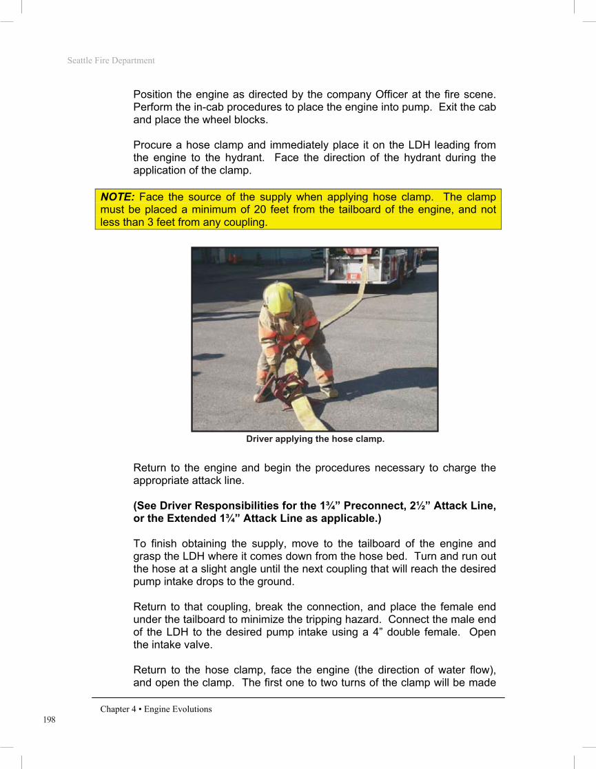
198
Seattle Fire Department
Chapter 4 • Engine Evolutions
Position the engine as directed by the company Officer at the fire scene. Perform the in-cab procedures to place the engine into pump. Exit the cab and place the wheel blocks. Procure a hose clamp and immediately place it on the LDH leading from the engine to the hydrant. Face the direction of the hydrant during the application of the clamp.
NOTE: Face the source of the supply when applying hose clamp. The clamp must be placed a minimum of 20 feet from the tailboard of the engine, and not less than 3 feet from any coupling.
PHOTO 4.113
Return to the engine and begin the procedures necessary to charge the appropriate attack line.
(See Driver Responsibilities for the 1¾” Preconnect, 2½” Attack Line, or the Extended 1¾” Attack Line as applicable.) To finish obtaining the supply, move to the tailboard of the engine and grasp the LDH where it comes down from the hose bed. Turn and run out the hose at a slight angle until the next coupling that will reach the desired pump intake drops to the ground. Return to that coupling, break the connection, and place the female end under the tailboard to minimize the tripping hazard. Connect the male end of the LDH to the desired pump intake using a 4” double female. Open the intake valve. Return to the hose clamp, face the engine (the direction of water flow), and open the clamp. The first one to two turns of the clamp will be made
Driver applying the hose clamp.

199
Seattle Fire Department
Chapter 4 • Engine Evolutions
in a rapid manner. Then continue to open the clamp with slow turns to prevent water hammer. Once fully open, remove the clamp and return it to the engine.
PHOTO 4.114
Return to the engine’s pump panel. If a significant kink is discovered while returning to the pump panel, remove it immediately. If kinks are present but it remains evident that water is entering the intake, disregard them at this time. Such kinks will be addressed at a later point. Close the tank-to-pump valve. Reduce the throttle to return the discharge pressure to the desired operating pressure. If the PRV was properly set, it will likely not require any adjustment. Upon completion of the primary supply, the driver will don the SCBA to a stand-by position and act as a member of the Firefighter Stand-by Rescue Team, if one is not already in place. Position traffic cones to protect personnel, the engine, and hose lines from approaching vehicles. While placing the cones, remove any remaining kinks in the supply line. If necessary, recommend to the incident commander that a second supply be laid by another engine company. Refill any water already used from the engine’s booster tank by opening the tank fill valve. Ensure remaining equipment and hose loads are ready for use. Monitor the pump panel and the radio for further instructions.
Position #3 Firefighter - When the engine comes to a stop at the
hydrant location, and the proper horn signal has been sounded, exit the
Face the direction of the flow when opening the hose clamp.
Seattle Fire Department
Chapter 4 • Engine Evolutions
ENGINE COMPANY INTRODUCTION
Overview
Engine company hose evolutions will follow a department-wide standard. The goal is to provide the most efficient methods of performing fire ground operations. All members shall possess a solid understanding of the operations described within this section, as they will serve as the basis for engine company fire ground operations. These evolutions will be used to evaluate Recruit Firefighter’s during drill school and Operations Division member’s throughout their careers. In some instances, emergency situations may not be satisfactorily resolved by utilizing only these basic evolutions. The company Officer maintains the ability to alter these standard methods when necessary.
It should be noted that the Seattle Fire Department Basic Skills Manual is not a tactics textbook. The knowledge and decision-making skills must be learned and practiced using approved curriculum and methods.
Introduction
Stretching and operating hose lines is the primary function of the engine company. All members must realize the importance of the initial line stretched at a structural fire. More lives are saved at fire operations by the proper positioning and operating of hose lines than by all other life-saving techniques available to firefighting forces. The majority of structural fires are controlled and extinguished by this initial line. The first hose line is placed between the fire and any persons endangered by it. Often this is accomplished by stretching the line via the primary means of egress; usually the main entrance or stairway. The purpose of this line is to: • Allow occupants to evacuate • Allow members to proceed to the floors above the fire for search • Confine and extinguish the fire
If it is determined there is no life hazard in the building, the first line is positioned between the fire and the most severe exposure. This will likely be an internal exposure (within the fire building) in the case of an offensive fire attack or an adjacent building in the event of a defensive fire attack.
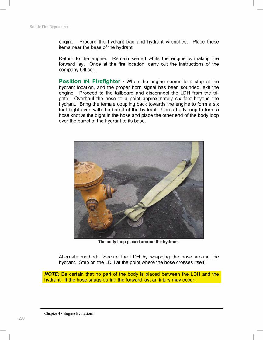
200
Seattle Fire Department
Chapter 4 • Engine Evolutions
engine. Procure the hydrant bag and hydrant wrenches. Place these items near the base of the hydrant. Return to the engine. Remain seated while the engine is making the forward lay. Once at the fire location, carry out the instructions of the company Officer.
Position #4 Firefighter - When the engine comes to a stop at the
hydrant location, and the proper horn signal has been sounded, exit the engine. Proceed to the tailboard and disconnect the LDH from the tri-gate. Overhaul the hose to a point approximately six feet beyond the hydrant. Bring the female coupling back towards the engine to form a six foot bight even with the barrel of the hydrant. Use a body loop to form a hose knot at the bight in the hose and place the other end of the body loop over the barrel of the hydrant to its base.
PHOTO 4.115
Alternate method: Secure the LDH by wrapping the hose around the hydrant. Step on the LDH at the point where the hose crosses itself.
NOTE: Be certain that no part of the body is placed between the LDH and the hydrant. If the hose snags during the forward lay, an injury may occur.
The body loop placed around the hydrant.

201
Seattle Fire Department
Chapter 4 • Engine Evolutions
PHOTO 4.116
Stand behind the hydrant, establish positive visual contact with the driver and signal the driver to proceed to the hydrant. This signal should be both audible and visual, by pointing forward while shouting “Go ahead.” Make the hydrant connections by attaching the LDH to the steamer port using a hydrant adaptor (yellow marking), and a hydrant gate on a 2 ½” port. Once you are certain that the driver has come to a stop and a hose gate has been placed, open the hydrant fully. If the position #4 firefighter’s vision is obstructed, use the radio to confirm the hose has been clamped.
NOTE: The use of the body loop allows the hydrant connections to be started before the engine has stopped at the fire, but members must stay clear of the utility strap while the engine is making the lay. The body loop must not be removed until the engine has stopped at the fire. Ensure that it is removed from the hydrant before the line is charged, however, in order to avoid a severe kink as the hose is filled.
While returning to the engine, remove any major kinks in the LDH to ensure a good supply is received at the engine’s intake. If the other members of the company have not yet entered the fire building, procure appropriate tools and assist in stretching the attack line. If the members are already inside the building, assist the driver as necessary, then report to the incident command for other instructions.
Correct positioning for securing the hose using the alternative method.
Seattle Fire Department
Chapter 4 • Engine Evolutions
ENGINE COMPANY INTRODUCTION
Overview
Engine company hose evolutions will follow a department-wide standard. The goal is to provide the most efficient methods of performing fire ground operations. All members shall possess a solid understanding of the operations described within this section, as they will serve as the basis for engine company fire ground operations. These evolutions will be used to evaluate Recruit Firefighter’s during drill school and Operations Division member’s throughout their careers. In some instances, emergency situations may not be satisfactorily resolved by utilizing only these basic evolutions. The company Officer maintains the ability to alter these standard methods when necessary.
It should be noted that the Seattle Fire Department Basic Skills Manual is not a tactics textbook. The knowledge and decision-making skills must be learned and practiced using approved curriculum and methods.
Introduction
Stretching and operating hose lines is the primary function of the engine company. All members must realize the importance of the initial line stretched at a structural fire. More lives are saved at fire operations by the proper positioning and operating of hose lines than by all other life-saving techniques available to firefighting forces. The majority of structural fires are controlled and extinguished by this initial line. The first hose line is placed between the fire and any persons endangered by it. Often this is accomplished by stretching the line via the primary means of egress; usually the main entrance or stairway. The purpose of this line is to: • Allow occupants to evacuate • Allow members to proceed to the floors above the fire for search • Confine and extinguish the fire
If it is determined there is no life hazard in the building, the first line is positioned between the fire and the most severe exposure. This will likely be an internal exposure (within the fire building) in the case of an offensive fire attack or an adjacent building in the event of a defensive fire attack.

202
Seattle Fire Department
Chapter 4 • Engine Evolutions
2 ½” Forward Lay (Wet/Dry) A forward lay can be accomplished by utilizing 2½” hose as the supply line. The LDH may be unavailable due to hose testing, a hose change, or if responding from another fire location. This type of forward lay may also be performed “wet” or “dry.” The evolution will be accomplished in a very similar fashion as those listed above, with the following exceptions:
• The supply line will be connected to the 2½” port on the fire side of the hydrant. The 2½” double female will be required to make this connection.
• A 2½” double male will be necessary to connect the supply line to the engine intake. The main side intake should remain available for the second supply (an LDH supply).
NOTE: A 2½” Forward Lay is not preferred due to the significant friction loss in the 2½” hose. Use this type of forward lay as a last resort.
Blind Alley Lay The Blind Alley Lay is a split lay that is accomplished with two engine companies. This lay may be utilized when a forward lay is required down an alley, private drive, or other limited access road. The first engine will drop the tri-gate at the entrance of the alley or private drive. This engine company will then perform the first half of the split lay. The LDH can be secured to a substantial object (e.g. mail box, fence post) with a body loop so that a member is not required to foot the tri-gate.
PHOTO 4.118
Initial engine company lays forward to the fire.

203
Seattle Fire Department
Chapter 4 • Engine Evolutions
Once at the fire location, an attack line will be stretched and fire suppression activities will begin with tank water, as described in the forward lay-dry section. The driver must place a hose clamp on the LDH immediately after setting the wheel blocks. After the designated attack line has been charged, the LDH will be broken and connected to the pump intake and the intake valve can be opened.
The second engine to arrive will basically perform a Reverse Lay evolution from the location of the tri-gate initially dropped by the first engine.
Officer (1st engine) - Upon determining that the fire is in a location
away from the main roadway and that a narrow alley or access road must be used, direct the driver to position the engine at the beginning of the alley or narrow roadway. Give verbal directions to the crew indicating a “Blind Alley Lay - Dry”. Remain seated in the engine until the Blind Alley Lay is completed. At the fire scene, indicate to the #3 and #4 firefighters the fire attack to perform. Don the SCBA, supervise, and assist the company in fire suppression and rescue activities.
Driver (1st engine) - Stop the engine as directed by the Officer. Sound
a single horn honk so that the position #4 firefighter knows it is safe to exit the engine. Remain in the cab and wait for the position #4 firefighter to return to the engine. Once the position #4 firefighter is secured in the engine, continue to the fire location as directed by the Officer. Position the engine as directed by the company Officer at the fire scene. Perform the in-cab procedures to place the engine into pump. Exit the cab and place the wheel blocks. Procure a hose clamp and immediately place it on the LDH leading from the engine.
NOTE: Face the source of the supply when applying hose clamp. The clamp must be placed a minimum of 20 feet from the tailboard of the engine, and not less than 3 feet from any coupling.
Return to the engine and begin the procedures necessary to charge the appropriate attack line. (See Driver Responsibilities for the 1¾” Preconnect, 2½” Attack Line, or the Extended 1¾” Attack Line as applicable.) To finish obtaining the supply, move to the tailboard of the engine and grasp the LDH where it comes down from the hose bed. Turn and run out the hose at a slight angle until the next coupling that will reach the desired pump intake drops to the ground.
Seattle Fire Department
Chapter 4 • Engine Evolutions
ENGINE COMPANY INTRODUCTION
Overview
Engine company hose evolutions will follow a department-wide standard. The goal is to provide the most efficient methods of performing fire ground operations. All members shall possess a solid understanding of the operations described within this section, as they will serve as the basis for engine company fire ground operations. These evolutions will be used to evaluate Recruit Firefighter’s during drill school and Operations Division member’s throughout their careers. In some instances, emergency situations may not be satisfactorily resolved by utilizing only these basic evolutions. The company Officer maintains the ability to alter these standard methods when necessary.
It should be noted that the Seattle Fire Department Basic Skills Manual is not a tactics textbook. The knowledge and decision-making skills must be learned and practiced using approved curriculum and methods.
Introduction
Stretching and operating hose lines is the primary function of the engine company. All members must realize the importance of the initial line stretched at a structural fire. More lives are saved at fire operations by the proper positioning and operating of hose lines than by all other life-saving techniques available to firefighting forces. The majority of structural fires are controlled and extinguished by this initial line. The first hose line is placed between the fire and any persons endangered by it. Often this is accomplished by stretching the line via the primary means of egress; usually the main entrance or stairway. The purpose of this line is to: • Allow occupants to evacuate • Allow members to proceed to the floors above the fire for search • Confine and extinguish the fire
If it is determined there is no life hazard in the building, the first line is positioned between the fire and the most severe exposure. This will likely be an internal exposure (within the fire building) in the case of an offensive fire attack or an adjacent building in the event of a defensive fire attack.

204
Seattle Fire Department
Chapter 4 • Engine Evolutions
Return to that coupling, break the connection, and place the female end under the tailboard to minimize the tripping hazard. Connect the male end of the LDH to the desired pump intake using a 4” double female. Open the intake valve. Return to the hose clamp, face the engine (the direction of water flow), and open the clamp. The first one to two turns of the clamp will be made in a rapid manner. Then continue to open the clamp with slow turns to prevent water hammer. Once fully open, remove the clamp and return it to the engine.
NOTE: Face the direction of water flow when opening a hose clamp. Ensure the hose is ready to receive the water supply and announce “water coming” in a loud voice.
Return to the engine’s pump panel. If a significant kink is discovered while returning to the pump panel, remove it immediately. If kinks are present but it remains evident that water is entering the intake, disregard them at this time. Such kinks will be addressed at a later point. Close the tank-to-pump valve. Reduce the throttle to return the discharge pressure to the desired operating pressure. If the PRV was properly set, it will likely not require any adjustment. Upon completion of the primary supply, the driver will don the SCBA to a stand-by position and act as a member of the Firefighter Stand-by Rescue Team, if one is not already in place. Position traffic cones to protect personnel, the engine, and hose lines from approaching vehicles. While placing the cones, remove any remaining kinks in the supply line. If necessary, recommend to the incident commander that a second supply be laid by another engine company. Refill any water already used from the engine’s booster tank by opening the tank fill valve. Ensure remaining equipment and hose loads are ready for use. Monitor the pump panel and the radio for further instructions.
Position #3 Firefighter (1st engine) - Remain on the engine until it
reaches the fire location. Once at the fire location, carry out the instructions of the company Officer.
Position #4 Firefighter (1st engine) - When the engine comes to a
stop at the hydrant location and the horn signal has been sounded, exit the engine. Remove the tri-gate with LDH attached and lay in the driveway, alley, or narrow roadway. If possible, secure the LDH to a substantial object (e.g. mail box, fence post) with a body loop.

205
Seattle Fire Department
Chapter 4 • Engine Evolutions
Return to the engine. Remain seated while the engine is making the forward lay. Once at the fire location, carry out the instructions of the company Officer
Officer (2nd engine) - Direct the driver to a location near the dropped
tri-gate of the initial engine. Consider sending the position #3 firefighter with the driver to facilitate a more rapid water supply connection. Instruct the crew to “Finish the “Blind Alley Lay.” Exit the cab after the driver sounds the proper horn signal. Remove the Officer’s SCBA and appropriate tools from the engine and place these items on the ground. Ensure that the amount of LDH hose removed from the 2nd engine is enough to make the connection to the initial engine’s LDH hose lay. Direct the position #4 firefighter to send the engine to the hydrant.
Driver (2nd engine) - Position the engine as directed by the Officer.
Sound a single horn honk so that the Officer and position #4 firefighter know that it is safe to exit the engine. Remain in the cab and look for the signal to proceed from the position #4 firefighter. When signaled to do so, perform the reverse lay to the nearest hydrant. Position the engine at the hydrant for a Reverse Pump Hook-up using the soft suction. Perform the in-cab procedures to place the engine into pump. Exit the cab and place the wheel blocks. (See the instructions for the “Reverse Pump Hook-up using the Soft Suction”)
Position #3 Firefighter (2nd engine) - Follow directions of the
Officer. If directed to the hydrant with the driver, remain in the cab while the engine makes its first stop, then proceed to the hydrant with the driver and assist with the reverse pump hook-up.
Position #4 Firefighter (2nd engine) - Exit the cab after the driver
sounds the proper horn signal. Procure a 4” double male and the tri-gate, with LDH attached, from their compartments. The position #4 firefighter will then foot the tri-gate and an additional amount of LDH to ensure that both lengths of LDH can be connected. On the Officer’s command, signal the driver to proceed to the hydrant. This signal should be both audible and visual, by pointing forward while shouting “Go ahead”. When it is safe to do so, remove both of the tri-gate’s from their respective hose lines. Connect the together using a 4” double male. The position #4 will then report to their company Officer for further assignment.
hose
Seattle Fire Department
Chapter 4 • Engine Evolutions
ENGINE COMPANY INTRODUCTION
Overview
Engine company hose evolutions will follow a department-wide standard. The goal is to provide the most efficient methods of performing fire ground operations. All members shall possess a solid understanding of the operations described within this section, as they will serve as the basis for engine company fire ground operations. These evolutions will be used to evaluate Recruit Firefighter’s during drill school and Operations Division member’s throughout their careers. In some instances, emergency situations may not be satisfactorily resolved by utilizing only these basic evolutions. The company Officer maintains the ability to alter these standard methods when necessary.
It should be noted that the Seattle Fire Department Basic Skills Manual is not a tactics textbook. The knowledge and decision-making skills must be learned and practiced using approved curriculum and methods.
Introduction
Stretching and operating hose lines is the primary function of the engine company. All members must realize the importance of the initial line stretched at a structural fire. More lives are saved at fire operations by the proper positioning and operating of hose lines than by all other life-saving techniques available to firefighting forces. The majority of structural fires are controlled and extinguished by this initial line. The first hose line is placed between the fire and any persons endangered by it. Often this is accomplished by stretching the line via the primary means of egress; usually the main entrance or stairway. The purpose of this line is to: • Allow occupants to evacuate • Allow members to proceed to the floors above the fire for search • Confine and extinguish the fire
If it is determined there is no life hazard in the building, the first line is positioned between the fire and the most severe exposure. This will likely be an internal exposure (within the fire building) in the case of an offensive fire attack or an adjacent building in the event of a defensive fire attack.
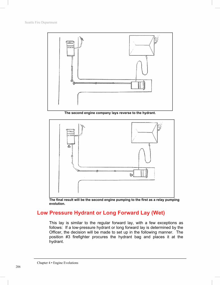
206
Seattle Fire Department
Chapter 4 • Engine Evolutions
The second engine company lays reverse to the hydrant.
The final result will be the second engine pumping to the first as a relay pumping evolution.
Low Pressure Hydrant or Long Forward Lay (Wet) This lay is similar to the regular forward lay, with a few exceptions as follows: If a low-pressure hydrant or long forward lay is determined by the Officer, the decision will be made to set up in the following manner. The position #3 firefighter procures the hydrant bag and places it at the hydrant.
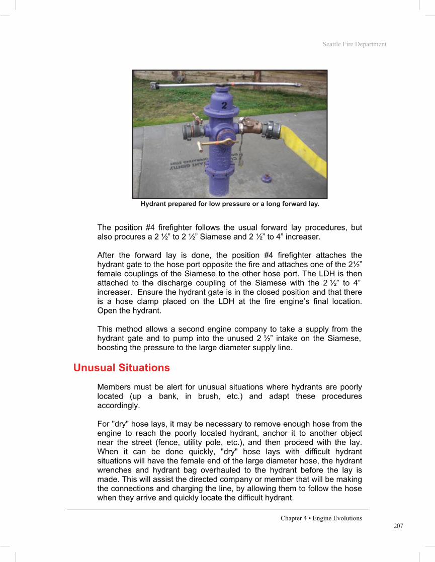
207
Seattle Fire Department
Chapter 4 • Engine Evolutions
PHOTO 4.121
The position #4 firefighter follows the usual forward lay procedures, but also procures a 2 ½” to 2 ½” Siamese and 2 ½” to 4” increaser. After the forward lay is done, the position #4 firefighter attaches the hydrant gate to the hose port opposite the fire and attaches one of the 2½” female couplings of the Siamese to the other hose port. The LDH is then attached to the discharge coupling of the Siamese with the 2 ½” to 4” increaser. Ensure the hydrant gate is in the closed position and that there is a hose clamp placed on the LDH at the fire engine’s final location. Open the hydrant. This method allows a second engine company to take a supply from the hydrant gate and to pump into the unused 2 ½” intake on the Siamese, boosting the pressure to the large diameter supply line.
Unusual Situations
Members must be alert for unusual situations where hydrants are poorly located (up a bank, in brush, etc.) and adapt these procedures accordingly. For "dry" hose lays, it may be necessary to remove enough hose from the engine to reach the poorly located hydrant, anchor it to another object near the street (fence, utility pole, etc.), and then proceed with the lay. When it can be done quickly, "dry" hose lays with difficult hydrant situations will have the female end of the large diameter hose, the hydrant wrenches and hydrant bag overhauled to the hydrant before the lay is made. This will assist the directed company or member that will be making the connections and charging the line, by allowing them to follow the hose when they arrive and quickly locate the difficult hydrant.
Hydrant prepared for low pressure or a long forward lay.
Seattle Fire Department
Chapter 4 • Engine Evolutions
ENGINE COMPANY INTRODUCTION
Overview
Engine company hose evolutions will follow a department-wide standard. The goal is to provide the most efficient methods of performing fire ground operations. All members shall possess a solid understanding of the operations described within this section, as they will serve as the basis for engine company fire ground operations. These evolutions will be used to evaluate Recruit Firefighter’s during drill school and Operations Division member’s throughout their careers. In some instances, emergency situations may not be satisfactorily resolved by utilizing only these basic evolutions. The company Officer maintains the ability to alter these standard methods when necessary.
It should be noted that the Seattle Fire Department Basic Skills Manual is not a tactics textbook. The knowledge and decision-making skills must be learned and practiced using approved curriculum and methods.
Introduction
Stretching and operating hose lines is the primary function of the engine company. All members must realize the importance of the initial line stretched at a structural fire. More lives are saved at fire operations by the proper positioning and operating of hose lines than by all other life-saving techniques available to firefighting forces. The majority of structural fires are controlled and extinguished by this initial line. The first hose line is placed between the fire and any persons endangered by it. Often this is accomplished by stretching the line via the primary means of egress; usually the main entrance or stairway. The purpose of this line is to: • Allow occupants to evacuate • Allow members to proceed to the floors above the fire for search • Confine and extinguish the fire
If it is determined there is no life hazard in the building, the first line is positioned between the fire and the most severe exposure. This will likely be an internal exposure (within the fire building) in the case of an offensive fire attack or an adjacent building in the event of a defensive fire attack.

208
Seattle Fire Department
Chapter 4 • Engine Evolutions
If the utility strap cannot be slipped over the top of the anchoring object, the free end of the utility strap will be tied to the object using a round turn and two half hitches. More than one utility strap can be looped together if greater length is needed. If the equipment and hose cannot be overhauled quickly to the hydrant, do not proceed with the lay until it is assured that sufficient hose has been provided to reach the hydrant from the street. The hydrant wrenches and hydrant bag will be left with the additional hose that was removed.
Extending the LDH with 2 ½” Hose There are times when the entire compliment of large diameter hose (LDH) will be depleted before the engine reaches its objective. This may be the case when making a long reverse or forward lay. The following describes the procedures to be followed when it is necessary to extend the LDH with 2½” during a Forward Lay–Wet, a Forward Lay–Dry, or a Reverse Lay evolution.
Forward Lay–Wet When the final LDH coupling drops from the hose bed, the driver stops the engine. The position #3 firefighter and the Officer exit the cab and procure the 2½” gated wye and a 2½” double female coupling. A 4” to 2½” reducer is already connected to the final coupling of LDH. One member attaches the 2½” gated wye to the 4” to 2½” reducer. The other member unties the first bundle of hose in the 2½” reverse bed and pulls the nozzle end down from the bed. The nozzle is disconnected and the 2½” double female is attached in its place. The 2½” hose can then be attached to the 2½” gated wye as shown below.
PHOTO 4.122
Extending LDH with 2 ½” hose during a forward lay.

209
Seattle Fire Department
Chapter 4 • Engine Evolutions
Both members then return to their seated positions on the engine so that the lay can be completed. The gated wye should be left in the closed position. After opening the hydrant, the position #4 firefighter will follow the supply line to the gated wye and open the appropriate valve. This will allow the driver time to complete the lay and clamp the supply line before water arrives.
Forward Lay–Dry When the final LDH coupling drops from the hose bed, the Driver stops the engine. The Position 3 and 4 firefighters will exit the cab to connect the 2½” to the LDH. All couplings and connections are the same as with the Forward Lay–Wet evolution. Open the gated wye valve when the connections have been made and before continuing on with the lay.
Reverse Lay
When the final LDH coupling drops from the hose bed, the driver stops the engine, sets the parking brake, and exits the cab to extend the lay. Procure the 2½” Siamese and a 2½” double female coupling. The 4” to 2½” reducer is already connected to the final coupling of LDH. The 2½” double female is attached to the 4” to 2½” reducer. The 2½” Siamese is connected to the 2½” double female coupling. The first bundle of hose in the 2½” reverse bed is untied and the nozzle end is pulled down from the bed. The nozzle is removed allowing the 2½” Siamese to be connected in its place.
No matter if extending a Forward or Reverse Lay, once the supply through the LDH has been established it must be a priority to provide a second 2½” line to the Siamese or gated wye. This parallel line is typically laid by another engine company. The supply line is not complete until this accomplished.
Replacing a Burst Section of LDH
In the event of a burst section of large diameter hose, the obvious replacement for the damaged hose would be another section of LDH.
NOTE: Recognize that two sections may be necessary to make the connection of LDH if the burst section was mostly straight prior to the hose failing.
Shutting the water down at the engine or hydrant is the preferred, and most efficient way, to stop the flow to the burst section and should be used unless this action would affect operating hose lines.
Seattle Fire Department
Chapter 4 • Engine Evolutions
ENGINE COMPANY INTRODUCTION
Overview
Engine company hose evolutions will follow a department-wide standard. The goal is to provide the most efficient methods of performing fire ground operations. All members shall possess a solid understanding of the operations described within this section, as they will serve as the basis for engine company fire ground operations. These evolutions will be used to evaluate Recruit Firefighter’s during drill school and Operations Division member’s throughout their careers. In some instances, emergency situations may not be satisfactorily resolved by utilizing only these basic evolutions. The company Officer maintains the ability to alter these standard methods when necessary.
It should be noted that the Seattle Fire Department Basic Skills Manual is not a tactics textbook. The knowledge and decision-making skills must be learned and practiced using approved curriculum and methods.
Introduction
Stretching and operating hose lines is the primary function of the engine company. All members must realize the importance of the initial line stretched at a structural fire. More lives are saved at fire operations by the proper positioning and operating of hose lines than by all other life-saving techniques available to firefighting forces. The majority of structural fires are controlled and extinguished by this initial line. The first hose line is placed between the fire and any persons endangered by it. Often this is accomplished by stretching the line via the primary means of egress; usually the main entrance or stairway. The purpose of this line is to: • Allow occupants to evacuate • Allow members to proceed to the floors above the fire for search • Confine and extinguish the fire
If it is determined there is no life hazard in the building, the first line is positioned between the fire and the most severe exposure. This will likely be an internal exposure (within the fire building) in the case of an offensive fire attack or an adjacent building in the event of a defensive fire attack.
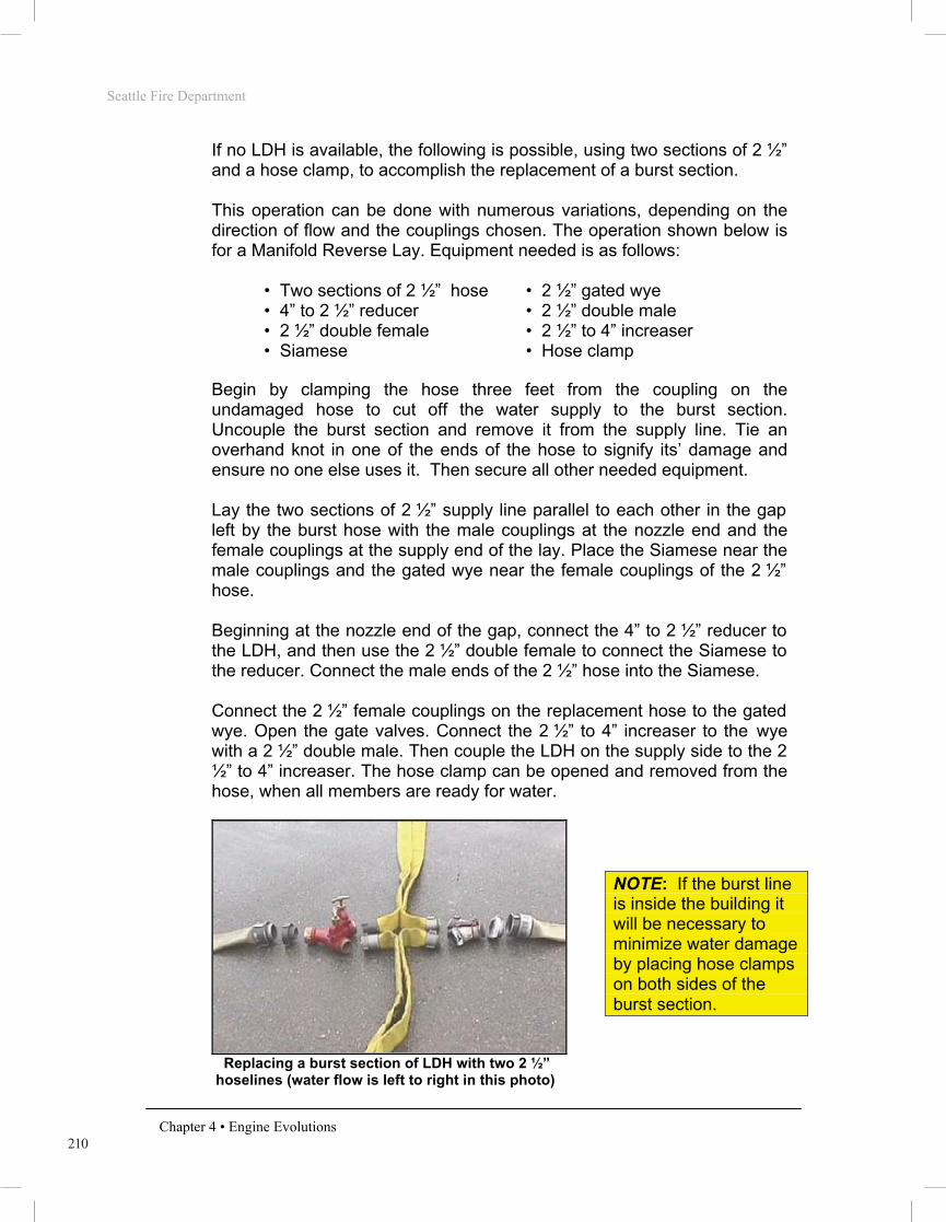
210
Seattle Fire Department
Chapter 4 • Engine Evolutions
If no LDH is available, the following is possible, using two sections of 2 ½” and a hose clamp, to accomplish the replacement of a burst section. This operation can be done with numerous variations, depending on the direction of flow and the couplings chosen. The operation shown below is for a Manifold Reverse Lay. Equipment needed is as follows:
• Two sections of 2 ½” hose • 2 ½” gated wye • 4” to 2 ½” reducer • 2 ½” double male • 2 ½” double female • 2 ½” to 4” increaser • Siamese • Hose clamp
Begin by clamping the hose three feet from the coupling on the undamaged hose to cut off the water supply to the burst section. Uncouple the burst section and remove it from the supply line. Tie an overhand knot in one of the ends of the hose to signify its’ damage and ensure no one else uses it. Then secure all other needed equipment. Lay the two sections of 2 ½” supply line parallel to each other in the gap left by the burst hose with the male couplings at the nozzle end and the female couplings at the supply end of the lay. Place the Siamese near the male couplings and the gated wye near the female couplings of the 2 ½” hose. Beginning at the nozzle end of the gap, connect the 4” to 2 ½” reducer to the LDH, and then use the 2 ½” double female to connect the Siamese to the reducer. Connect the male ends of the 2 ½” hose into the Siamese. Connect the 2 ½” female couplings on the replacement hose to the gated wye. Open the gate valves. Connect the 2 ½” to 4” increaser to the wye with a 2 ½” double male. Then couple the LDH on the supply side to the 2 ½” to 4” increaser. The hose clamp can be opened and removed from the hose, when all members are ready for water.
Replacing a burst section of LDH with two 2 ½” hoselines (water flow is left to right in this photo)
NOTE: If the burst line is inside the building it will be necessary to minimize water damage by placing hose clamps on both sides of the burst section.