Embed Size (px)
Citation preview

STATE OF NEW YORK PUBLIC SERVICE COMMISSION
Joint Petition of Entergy Nuclear Indian Point 2, LLC; Entergy Nuclear Indian Point 3, LLC; and Nuclear Asset Management Company, LLC for a Declaratory Ruling Disclaiming Jurisdiction Over or Abstaining from Review of the Proposed Transfers or, in the Alternative, an Order Approving the Proposed Transfers Pursuant to Section 70 of the New York Public Service Law __________________________________________________
Case 19-E-0730
REPLY COMMENTS OF JOINT PETITIONERS IN RESPONSE TO COMMISSION JANUARY 17, 2020 NOTICE SEEKING COMMENTS
Exhibit 2
Historical Site Assessment

Historical Site Assessment for Indian Point Energy Center
Technical Support Document (TSD) No. 19-002 Rev 02
Prepared by
Radiation Safety & Control Services, Inc. 93 Ledge Road Seabrook, NH 03874 1-800-525-8339 (603) 778-2871 (Outside USA) www.radsafety.com
Created on: April 30, 2019
Latest Revision: 02

RSCS TSD 19-002 Rev 02
Page 2 of 371
Historical Site Assessment for Indian Point Energy Center
Technical Support Document No. 19-002 Rev 02
Originated by:
David Scott, Professional Geologist, LEP
Originated by:
Robert Leddy, Sr. Health Physicist
Reviewed by:
Adam Kryskow, Certified Health Physicist
Reviewed by:
Greg Babineau, Director of Radiological Services
Approved by:
Eric Darois, Executive Director CHP

RSCS TSD 19-002 Rev 02
Page 3 of 371
Table of Contents
1 Executive Summary ........................................................................................ 15
2 Glossary of Key Terms .................................................................................... 18
3 Introduction ................................................................................................... 23
4 Property Identification ................................................................................... 27
Environmental Setting .................................................................................... 28
4.1.1 Physiography .............................................................................................. 28
4.1.2 Geology ...................................................................................................... 28
4.1.3 Hydrology ................................................................................................... 28
4.1.4 Climatology ................................................................................................ 29
4.1.5 Meteorology ............................................................................................... 30
IPEC Conceptual Site Model ............................................................................ 30
4.2.1 Hydrogeologic Setting ................................................................................. 31
4.2.2 Potential Sources of Environmental Contamination ........................................ 32
4.2.2.1 Potential Non-Radiological Contaminant Sources ................................. 32
4.2.2.2 Potential Radiological Contaminant Sources ........................................ 41
4.2.2.3 Groundwater Impacts ........................................................................ 45
4.2.3 Contaminant Transport ................................................................................ 47
4.2.4 Potential Contaminant Receptors ................................................................. 48
5 MARSSIM Investigation Process .................................................................... 50
Approach and Rationale .................................................................................. 50
5.1.1 Historical Site Assessment ........................................................................... 50
5.1.2 Scoping Survey ........................................................................................... 52
5.1.3 Characterization Survey ............................................................................... 52
5.1.4 Remedial Action Support Survey .................................................................. 53
5.1.5 Final Status Survey ..................................................................................... 53
5.1.5.1 Planning ........................................................................................... 53
5.1.5.2 Design .............................................................................................. 54
5.1.5.3 Implementation ................................................................................ 55

RSCS TSD 19-002 Rev 02
Page 4 of 371
5.1.5.4 Assessment ...................................................................................... 55
5.1.6 Regulatory Agency Confirmation and Verification .......................................... 55
Documents Reviewed ..................................................................................... 56
Property Inspections ....................................................................................... 56
Personnel Interviews ...................................................................................... 56
6 Assessment Findings ...................................................................................... 58
Non-Impacted Areas ....................................................................................... 58
6.1.1 Non-Radiological ......................................................................................... 58
6.1.2 Radiological ................................................................................................ 60
Site-Wide Non-Radiological and Radiological Impacts ....................................... 62
6.2.1 Asbestos-Containing Material ....................................................................... 62
6.2.2 Lead and Lead-Based Paint .......................................................................... 63
6.2.3 Mercury-Containing components .................................................................. 64
6.2.4 PCB-Containing Components........................................................................ 65
6.2.5 Sewage Collection System ........................................................................... 67
6.2.6 Storm Drain System .................................................................................... 68
Unit 1 Impacts ............................................................................................... 70
6.3.1 Non-Radiological Impacts ............................................................................ 70
6.3.1.1 Building or Structure ......................................................................... 70
6.3.1.1.1 U1 Contractor Fabrication Shop ............................................................................... 70
6.3.1.1.2 U1 Gas Turbine 1 Generator Building ....................................................................... 71
6.3.1.1.3 U1 Monitor House and Utility Tunnel ........................................................................ 73
6.3.1.1.4 U1 Turbine Generator Building ................................................................................ 74
6.3.1.2 Oil-Filled Mechanical Equipment ......................................................... 75
6.3.1.2.1 U1 Building Elevators .............................................................................................. 75
6.3.1.3 Exterior Area .................................................................................... 76
6.3.1.3.1 U1 Former Transformer Area .................................................................................. 76
6.3.1.4 Storage Tanks .................................................................................. 77
6.3.1.4.1 U1 Bulk Oil Storage Tanks 11 and 12 ....................................................................... 77
6.3.1.4.2 U1 Ignition Oil Tank 11IOT ..................................................................................... 78
6.3.1.4.3 U1 Ignition Oil Tank 12IOT ..................................................................................... 79

RSCS TSD 19-002 Rev 02
Page 5 of 371
6.3.1.5 Transformers .................................................................................... 81
6.3.1.5.1 U1 Hellgate Transformer ......................................................................................... 81
6.3.1.5.2 U1 138 kV Underground Cable ................................................................................ 82
6.3.2 Radiological Impacts ................................................................................... 84
6.3.2.1 Radionuclides of Concern .................................................................. 84
6.3.2.2 Building or Structure ......................................................................... 87
6.3.2.2.1 U1 Chemical Systems Building ................................................................................. 87
6.3.2.2.2 U1 Containment Building ........................................................................................ 90
6.3.2.2.3 U1 Contractor Fabrication Shop ............................................................................... 92
6.3.2.2.4 U1 Fuel Storage Building ......................................................................................... 93
6.3.2.2.5 U1 Monitor House and Utility Tunnel ........................................................................ 95
6.3.2.2.6 U1 Gas Turbine 1 Generator Building ....................................................................... 96
6.3.2.2.7 U1 Nuclear Service Building..................................................................................... 98
6.3.2.2.8 U1 Screenwell House ............................................................................................ 100
6.3.2.2.9 U1 Superheater & Administration Building .............................................................. 101
6.3.2.2.10 U1 Turbine Generator Building ............................................................................ 103
6.3.2.3 Exterior Area ................................................................................... 105
6.3.2.3.1 U1 Former Septic Leach Field ................................................................................ 105
Unit 2 Impacts .............................................................................................. 107
6.4.1 Non-Radiological Impacts ........................................................................... 107
6.4.1.1 Building or Structure ........................................................................ 107
6.4.1.1.1 U2 Emergency Diesel Generator Building ............................................................... 107
6.4.1.1.2 U2 Intake Structure .............................................................................................. 108
6.4.1.1.3 U2 Turbine Generator Building .............................................................................. 109
6.4.1.2 Chemical and Drum Storage Areas .................................................... 111
6.4.1.2.1 U2 Hazardous Waste Storage Bin .......................................................................... 111
6.4.1.2.2 U2 Oil Storage Cabinets ........................................................................................ 112
6.4.1.3 Exterior Area ................................................................................... 114
6.4.1.3.1 U2 Transformer Yard ............................................................................................ 114
6.4.1.4 Oil-Filled Mechanical Equipment ........................................................ 116
6.4.1.4.1 U2 Appendix R Diesel Generator ............................................................................ 116
6.4.1.4.2 U2 Circulation Water Pump Motors ........................................................................ 117
RSCS TSD 19-002 Rev 02
Page 6 of 371
6.4.1.4.3 U2 Condensate Pump Motors ................................................................................ 118
6.4.1.4.4 U2 Diesel Fire Pump Motor .................................................................................... 119
6.4.1.4.5 U2 Emergency Diesel Generators ........................................................................... 120
6.4.1.4.6 U2 Technical Support Center Emergency Diesel Generator ...................................... 121
6.4.1.5 Storage Tanks ................................................................................. 122
6.4.1.5.1 U2 21 Emergency Diesel Generator Day Tank 21FODT ........................................... 122
6.4.1.5.2 U2 21 Emergency Diesel Generator Storage Tank 21FOST ...................................... 123
6.4.1.5.3 U2 21 Main Boiler Feed Pump Oil Accumulator Tank 21OATA .................................. 124
6.4.1.5.4 U2 21 Main Boiler Feed Pump Oil Accumulator Tank 21OATB .................................. 125
6.4.1.5.5 U2 22 Emergency Diesel Generator Day Tank 22FODT ........................................... 126
6.4.1.5.6 U2 22 Emergency Diesel Generator Storage Tank 22FOST ...................................... 127
6.4.1.5.7 U2 22 Main Boiler Feed Pump Oil Accumulator Tank 22OATA .................................. 128
6.4.1.5.8 U2 22 Main Boiler Feed Pump Oil Accumulator Tank 22OATB .................................. 129
6.4.1.5.9 U2 23 Emergency Diesel Generator Day Tank 23FODT ........................................... 130
6.4.1.5.10 U2 23 Emergency Diesel Generator Storage Tank 23FOST .................................... 131
6.4.1.5.11 U2 Appendix R Diesel Generator Day Tank 2APPR ................................................ 132
6.4.1.5.12 U2 Boiler Feed Pump Oil Console BFOC ................................................................ 133
6.4.1.5.13 U2 Boiler Feed Pump Turbine Oil Conditioner BFPTOC .......................................... 134
6.4.1.5.14 U2 Clean Lube Oil Storage Tank COST ................................................................. 135
6.4.1.5.15 U2 Dirty Oil Storage Tank DOST .......................................................................... 136
6.4.1.5.16 U2 Fire Pump Diesel Storage Tank DFPFOT .......................................................... 137
6.4.1.5.17 U2 Gas Turbine 1 Fuel Oil Dump Tank GT1FODT .................................................. 138
6.4.1.5.18 U2 Gas Turbine 1 Lube Oil Reservoir GT1LOR....................................................... 139
6.4.1.5.19 U2 Gas Turbine 1 Storage Tank GT1FOT11 .......................................................... 140
6.4.1.5.20 U2 Gas Turbine 1 Storage Tank GT1FOT12 .......................................................... 142
6.4.1.5.21 U2 Hydrogen Seal Oil Reservoir HSOT .................................................................. 144
6.4.1.5.22 U2 Main Boiler Feed Pump Lube Oil Reservoir MBR ............................................... 145
6.4.1.5.23 U2 Main Lube Oil Reservoir TLOR ........................................................................ 146
6.4.1.5.24 U2 Main Turbine Generator Bearing Oil Drain Tank BODT ..................................... 147
6.4.1.5.25 U2 Main Turbine Oil Conditioner MTOC ................................................................ 148
6.4.1.5.26 U2 R2D2 Lube Oil Sludge Tank R2D2ST ............................................................... 149
6.4.1.5.27 U2 Westphalia Separator Sludge Tank LOSTSST ................................................... 150
6.4.1.5.28 U2 Technical Support Center Diesel Tank TSCFODT .............................................. 151
6.4.1.6 Transformers ................................................................................... 153
6.4.1.6.1 U2 Main Transformer 21 ....................................................................................... 153

RSCS TSD 19-002 Rev 02
Page 7 of 371
6.4.1.6.2 U2 Main Transformer 22 ....................................................................................... 154
6.4.1.6.3 U2 New Simulator L&P Transformer ....................................................................... 155
6.4.1.6.4 U2 Spare Station Auxiliary Transformer .................................................................. 156
6.4.1.6.5 U2 Station Auxiliary Transformer ........................................................................... 157
6.4.1.6.6 U2 Substation A Transformer ................................................................................ 158
6.4.1.6.7 U2 Test Transformer (L & P Room)........................................................................ 159
6.4.1.6.8 U2 Unit Auxiliary Transformer ............................................................................... 160
6.4.2 Radiological Impacts .................................................................................. 162
6.4.2.1 Radionuclides of Concern ................................................................. 162
6.4.2.2 Building or Structure ........................................................................ 166
6.4.2.2.1 U2 Boric Acid Evaporator Building .......................................................................... 166
6.4.2.2.2 U2 Containment Building ...................................................................................... 167
6.4.2.2.3 U2 Control Building ............................................................................................... 169
6.4.2.2.4 U2 Emergency Diesel Generator Building ............................................................... 170
6.4.2.2.5 U2 Fuel Storage Building ....................................................................................... 171
6.4.2.2.6 U2 Maintenance Outage Building ........................................................................... 173
6.4.2.2.7 U2 Original Steam Generator Storage Facility ......................................................... 174
6.4.2.2.8 U2 Primary Auxiliary Building................................................................................. 175
6.4.2.2.9 U2 Turbine Generator Building .............................................................................. 177
6.4.2.3 Exterior Area ................................................................................... 178
6.4.2.3.1 U2 Fuel Storage Building Alleyway ......................................................................... 178
6.4.2.3.2 U2 Retired RAM Pen ............................................................................................. 180
6.4.2.3.3 U2 Transformer Yard ............................................................................................ 181
6.4.2.4 Storage Tanks ................................................................................. 182
6.4.2.4.1 U2 Condensate Storage Tank CST ......................................................................... 182
6.4.2.4.2 U2 Monitor Tanks ................................................................................................. 183
6.4.2.4.3 U2 Primary Water Storage Tank PWST .................................................................. 184
6.4.2.4.4 U2 Refueling Water Storage Tank RWST ................................................................ 185
Unit 3 Impacts .............................................................................................. 186
6.5.1 Non-Radiological Impacts ........................................................................... 186
6.5.1.1 Building or Structure ........................................................................ 186
6.5.1.1.1 U3 Auxiliary Feedwater Pump Building ................................................................... 186
6.5.1.1.2 U3 Circulation Water Pump Building....................................................................... 187

RSCS TSD 19-002 Rev 02
Page 8 of 371
6.5.1.1.3 U3 Emergency Diesel Generator Building ............................................................... 188
6.5.1.1.4 U3 Intake Structure .............................................................................................. 189
6.5.1.1.5 U3 Radioactive Machine Shop................................................................................ 190
6.5.1.1.6 U3 Turbine Generator Building .............................................................................. 191
6.5.1.2 Chemical and Drum Storage Areas .................................................... 193
6.5.1.2.1 U3 Hazardous Waste Storage Building ................................................................... 193
6.5.1.3 Exterior Area ................................................................................... 195
6.5.1.3.1 U3 Soil Pile Posted as Lead Hazard ........................................................................ 195
6.5.1.3.2 U3 Transformer Yard ............................................................................................ 196
6.5.1.4 Oil-Filled Mechanical Equipment ........................................................ 197
6.5.1.4.1 U3 Appendix R Diesel Generator ............................................................................ 197
6.5.1.4.2 U3 Building Elevators ............................................................................................ 198
6.5.1.4.3 U3 Circulation Water Pump Motors ........................................................................ 199
6.5.1.4.4 U3 Condensate Pump Motors ................................................................................ 200
6.5.1.4.5 U3 Diesel Fire Pump Motor .................................................................................... 201
6.5.1.4.6 U3 Emergency Diesel Generators ........................................................................... 202
6.5.1.4.7 U3 Technical Support Center Emergency Diesel Generator ...................................... 203
6.5.1.5 Storage Tanks ................................................................................. 204
6.5.1.5.1 U3 31 Emergency Diesel Generator Day Tank DD1 ................................................. 204
6.5.1.5.2 U3 31 Emergency Diesel Generator Storage Tank 31EDG ........................................ 205
6.5.1.5.3 U3 31 Main Boiler Feed Pump Oil Accumulator Tank 31LOA .................................... 206
6.5.1.5.4 U3 32 Emergency Diesel Generator Day Tank DD2 ................................................. 207
6.5.1.5.5 U3 32 Emergency Diesel Generator Storage Tank 32EDG ........................................ 208
6.5.1.5.6 U3 32 Main Boiler Feed Pump Oil Accumulator Tank 32LOA .................................... 209
6.5.1.5.7 U3 33 Emergency Diesel Generator Day Tank DD3 ................................................. 210
6.5.1.5.8 U3 33 Emergency Diesel Generator Storage Tank 33EDG ........................................ 211
6.5.1.5.9 U3 Fire Pump Diesel Tank FPD .............................................................................. 212
6.5.1.5.10 U3 Appendix R Diesel Storage Tank APR .............................................................. 213
6.5.1.5.11 U3 Clean Oil Storage Tank COST ......................................................................... 214
6.5.1.5.12 U3 Dirty Oil Storage Tank DOST .......................................................................... 215
6.5.1.5.13 U3 House Service Boiler Day Tank HSB ................................................................ 216
6.5.1.5.14 U3 Main Boiler Feed Pump Lube Oil Reservoir MBR ............................................... 217
6.5.1.5.15 U3 Main Lube Oil Reservoir MLO .......................................................................... 218
6.5.1.5.16 U3 Main Turbine Generator Bearing Oil Drain Tank BODT ..................................... 220

RSCS TSD 19-002 Rev 02
Page 9 of 371
6.5.1.5.17 U3 Main Turbine Generator Loop Seal Vapor Extractor Drain Tank LSVEDT ............ 221
6.5.1.5.18 U3 Main Turbine Generator Oil Reservoir Vapor Extractor Drain Tank RVEDT ......... 222
6.5.1.5.19 U3 Meteorological System Diesel Storage Tank MET ............................................. 223
6.5.1.5.20 U3 Portable Diesel Storage Tank TC3 ................................................................... 224
6.5.1.5.21 U3 Portable Kerosene Storage Tank TC2 .............................................................. 225
6.5.1.5.22 U3 R2D2 Lube Oil Sludge Tank R2D2ST ............................................................... 226
6.5.1.5.23 U3 R4D4 Lube Oil Sludge Tank R4S ..................................................................... 227
6.5.1.5.24 U3 Sewage Treatment Plant Diesel Storage Tank STP ........................................... 228
6.5.1.5.25 U3 Sewage Treatment Plant Fuel Oil Day Tank SPFODT ........................................ 229
6.5.1.5.26 U3 Station Outside Diesel Air Compressor Storage Tank ACD ................................ 230
6.5.1.5.27 U3 Technical Support Center Diesel Day Tank TSD ............................................... 231
6.5.1.5.28 U3 Technical Support Center Diesel Storage Tank TSC .......................................... 232
6.5.1.5.29 U3 Training Center Fuel Oil Storage Tank TC1 ...................................................... 233
6.5.1.5.30 U3 Training Fire Pump Diesel Storage Tank FP2 ................................................... 234
6.5.1.6 Transformers ................................................................................... 236
6.5.1.6.1 U3 31 Main Transformer ....................................................................................... 236
6.5.1.6.2 U3 32 Main Transformer ....................................................................................... 238
6.5.1.6.3 U3 GT Turbine Transformer .................................................................................. 239
6.5.1.6.4 U3 Spare Main Transformer .................................................................................. 240
6.5.1.6.5 U3 Spare Station Auxiliary Transformer .................................................................. 241
6.5.1.6.6 U3 Station Auxiliary Transformer ........................................................................... 242
6.5.1.6.7 U3 Unit Auxiliary Transformer ............................................................................... 243
6.5.2 Radiological Impacts .................................................................................. 245
6.5.2.1 Radionuclides of Concern ................................................................. 245
6.5.2.2 Building or Structure ........................................................................ 249
6.5.2.2.1 U3 Administration Building .................................................................................... 249
6.5.2.2.2 U3 Auxiliary Feedwater Pump Building ................................................................... 250
6.5.2.2.3 U3 Circulation Water Pump Building....................................................................... 251
6.5.2.2.4 U3 Condensate Polisher Building ........................................................................... 252
6.5.2.2.5 U3 Containment Building ...................................................................................... 253
6.5.2.2.6 U3 Control Building ............................................................................................... 255
6.5.2.2.7 U3 Emergency Diesel Generator Building ............................................................... 256
6.5.2.2.8 U3 Fuel Storage Building ....................................................................................... 257
6.5.2.2.9 U3 Original Security Access Building ...................................................................... 259

RSCS TSD 19-002 Rev 02
Page 10 of 371
6.5.2.2.10 U3 Original Steam Generator Storage Facility ....................................................... 260
6.5.2.2.11 U3 Outage Support Building ................................................................................ 261
6.5.2.2.12 U3 Primary Auxiliary Building ............................................................................... 262
6.5.2.2.13 U3 Radioactive Machine Shop .............................................................................. 265
6.5.2.2.14 U3 Retired Security Access Building ..................................................................... 266
6.5.2.2.15 U3 Turbine Generator Building ............................................................................ 267
6.5.2.3 Exterior Area ................................................................................... 268
6.5.2.3.1 U3 302 Exemption Area ........................................................................................ 268
6.5.2.3.2 U3 Fuel Storage Building Alleyway ......................................................................... 269
6.5.2.3.3 U3 Transformer Yard ............................................................................................ 271
6.5.2.3.4 U3 VC-FSB-PAB Junction ....................................................................................... 272
6.5.2.4 Storage Tanks ................................................................................. 273
6.5.2.4.1 U3 Condensate Polishing Facility Process Tanks CPFPT ........................................... 273
6.5.2.4.2 U3 Condensate Storage Tank CST ......................................................................... 274
6.5.2.4.3 U3 Monitor Tanks ................................................................................................. 275
6.5.2.4.4 U3 Primary Water Storage Tank PWST .................................................................. 276
6.5.2.4.5 U3 Refueling Water Storage Tank RWST ................................................................ 277
Impacts to Facilities Common to Multiple Units ................................................ 278
6.6.1 Non-Radiological Impacts ........................................................................... 278
6.6.1.1 Building or Structure ........................................................................ 278
6.6.1.1.1 COMMON Discharge Canal .................................................................................... 278
6.6.1.1.2 COMMON FLEX Building ........................................................................................ 280
6.6.1.1.3 COMMON Gas Turbines 2 & 3 ................................................................................ 281
6.6.1.1.4 COMMON ISFSI Heavy Hauler Storage Building ...................................................... 282
6.6.1.1.5 COMMON Maintenance Training Facility ................................................................. 283
6.6.1.1.6 COMMON Receiving Warehouse ............................................................................ 284
6.6.1.1.7 COMMON Salt Barn .............................................................................................. 285
6.6.1.1.8 COMMON Waterfront Warehouse .......................................................................... 286
6.6.1.2 Chemical and Drum Storage Areas .................................................... 287
6.6.1.2.1 COMMON Hazardous Material Storage Building ....................................................... 287
6.6.1.3 Oil-Filled Mechanical Equipment ........................................................ 288
6.6.1.3.1 COMMON Building Elevators .................................................................................. 288
6.6.1.4 Storage Tanks ................................................................................. 289

RSCS TSD 19-002 Rev 02
Page 11 of 371
6.6.1.4.1 COMMON Former Buchanan Service Center USTs ................................................... 289
6.6.1.4.2 COMMON Gas Turbine 2 Lube Oil Reservoir GT2LOR .............................................. 290
6.6.1.4.3 COMMON Gas Turbine 2 Used Oil Tank GT2LFST ................................................... 291
6.6.1.4.4 COMMON Gas Turbine 2&3 Storage Tank GT2&3FOT ............................................. 292
6.6.1.4.5 COMMON Gas Turbine 3 Lube Oil Reservoir GT3LOR .............................................. 293
6.6.1.4.6 COMMON Gas Turbine 3 Used Oil Tank GT3LFST ................................................... 294
6.6.1.4.7 COMMON Maintenance Training Facility Tank MTF02 .............................................. 295
6.6.1.4.8 COMMON Security Diesel Storage Tank SDFT ......................................................... 296
6.6.1.5 Transformers ................................................................................... 297
6.6.1.5.1 COMMON Buchanan Service Center Transformer .................................................... 297
6.6.1.5.2 COMMON GT2 Auxiliary Power Transformer Auxiliary Supply ................................... 298
6.6.1.5.3 COMMON GT2 Auxiliary Power Transformer Normal Supply ..................................... 299
6.6.1.5.4 COMMON Substation C Transformer ...................................................................... 300
6.6.2 Radiological Impacts .................................................................................. 301
6.6.2.1 Building or Structure ........................................................................ 301
6.6.2.1.1 COMMON Protected Area Cafeteria ........................................................................ 301
6.6.2.1.2 COMMON Discharge Canal .................................................................................... 302
6.6.2.1.3 COMMON FLEX Building ........................................................................................ 303
6.6.2.1.4 COMMON Gas Turbines 2 & 3 ................................................................................ 304
6.6.2.1.5 COMMON ISFSI Heavy Hauler Storage Building ...................................................... 305
6.6.2.1.6 COMMON Former Con Edison Visitor Center ........................................................... 306
6.6.2.1.7 COMMON Outage Contractor Offices ...................................................................... 307
6.6.2.1.8 COMMON Protected Area Access Facility ................................................................ 308
6.6.2.1.9 COMMON Retired Sewage Treatment Plant ............................................................ 309
6.6.2.1.10 COMMON Security Facility ................................................................................... 310
6.6.2.1.11 COMMON Waterfront Warehouse ......................................................................... 311
6.6.2.2 Exterior Area ................................................................................... 312
6.6.2.2.1 COMMON ISFSI Pad ............................................................................................. 312
6.6.2.2.2 COMMON Plant Yard ............................................................................................. 313
6.6.2.2.3 COMMON Radioactive Material Pen 1 ..................................................................... 316
6.6.2.2.4 COMMON Radioactive Material Pen 2 ..................................................................... 317
6.6.2.2.5 COMMON Yard 8 .................................................................................................. 318
6.6.2.3 Storage Tanks ................................................................................. 319
6.6.2.3.1 COMMON Waste Distillate Tanks ........................................................................... 319

RSCS TSD 19-002 Rev 02
Page 12 of 371
7 Conclusions ................................................................................................... 320
8 Cited References........................................................................................... 323
9 Appendices ................................................................................................... 327
A. Documents Reviewed ........................................................................................ 327
B. Summary Table of Potentially Impacted Non-Radiological Areas .......................... 346
C. Summary Table of Potentially Impacted Radiological Areas ................................. 354
D. Document Figures ............................................................................................ 358

RSCS TSD 19-002 Rev 02
Page 13 of 371
List of Tables
TABLE 1: SUMMARY OF CORRECTIVE ACTION REPORTS CONCERNING NON-RADIOLOGICAL
INCIDENTS AT ..................................................................................................... 34
TABLE 2: NEW YORK DEPARTMENT OF ENVIRONMENTAL CONSERVATION SPILL REPORTS ...... 35
TABLE 3: SUMMARY OF EVENTS CONCERNING RADIOLOGICAL INCIDENTS AT IPEC .............. 43
TABLE 4: IPEC EMPLOYEE DISCUSSION SUBJECTS.......................................................... 57
TABLE 5: UNIT 1 COMPOSITE LIST OF POSITIVELY IDENTIFIED RADIONUCLIDES ................. 84
TABLE 6: UNIT 1 CATEGORIZED RADIONUCLIDES OF CONCERN ......................................... 85
TABLE 7: UNIT 1 CHEMICAL SYSTEMS BUILDING SURVEY SUMMARY (MR/H) ...................... 87
TABLE 8: UNIT 1 CONTAINMENT BUILDING SURVEY SUMMARY (MR/H) ............................. 90
TABLE 9: UNIT 1 NUCLEAR SERVICE BUILDING SURVEY SUMMARY (MR/H) ........................ 98
TABLE 10: UNIT 2 COMPOSITE LIST OF POSITIVELY IDENTIFIED RADIONUCLIDES ............. 162
TABLE 11: UNIT 2 CATEGORIZED RADIONUCLIDES OF CONCERN ..................................... 163
TABLE 12: UNIT 2 CONTAINMENT BUILDING SURVEY SUMMARY (MR/H) ......................... 167
TABLE 13: UNIT 2 PRIMARY AUXILIARY BUILDING SURVEY SUMMARY (MR/H) ................ 175
TABLE 14: UNIT 3 COMPOSITE LIST OF POSITIVELY IDENTIFIED RADIONUCLIDES ............. 245
TABLE 15: UNIT 3 CATEGORIZED RADIONUCLIDES OF CONCERN ..................................... 246
TABLE 16: UNIT 3 CONTAINMENT BUILDING SURVEY SUMMARY (MR/H) ......................... 253
TABLE 17: UNIT 3 PRIMARY AUXILIARY BUILDING SURVEY SUMMARY (MR/H) ................ 262
TABLE 18: ADDITIONAL PLANT YARD AREAS ............................................................... 313
List of Figures
FIGURE 1: LOCATION OF THE INDIAN POINT ENERGY CENTER ......................................... 358
FIGURE 2: LOCATION OF PARCEL BOUNDARIES AT THE INDIAN POINT ENERGY CENTER ....... 359
FIGURE 3A: LOCATIONS OF FACILITIES AT THE INDIAN POINT ENERGY CENTER ................. 360
FIGURE 3B: LOCATIONS OF FACILITIES AT THE INDIAN POINT ENERGY CENTER ................. 361
FIGURE 3C: LOCATIONS OF FACILITIES AT THE INDIAN POINT ENERGY CENTER ................. 362
FIGURE 4: LOCATIONS AND PRELIMINARY CLASSIFICATIONS OF HAZARDOUS MATERIAL
STORAGE AREAS AND TRANSFORMERS IN THE AREA OF UNITS 1 AND 2 AT INDIAN POINT
ENERGY CENTER ............................................................................................... 363
FIGURE 5: LOCATIONS AND PRELIMINARY CLASSIFICATIONS OF HAZARDOUS MATERIAL
STORAGE AREAS AND TRANSFORMERS IN THE AREA OF UNIT 3 AT INDIAN POINT ENERGY
CENTER ........................................................................................................... 364

RSCS TSD 19-002 Rev 02
Page 14 of 371
FIGURE 6: PRELIMINARY RADIOLOGICAL AND NON-RADIOLOGICAL CLASSIFICATIONS OF THE
STORM DRAIN SYSTEM AT THE INDIAN POINT ENERGY CENTER ................................. 365
FIGURE 7A: PRELIMINARY NON-RADIOLOGICAL CLASSIFICATIONS OF FACILITIES AT THE
INDIAN POINT ENERGY CENTER ........................................................................... 366
FIGURE 7B: PRELIMINARY NON-RADIOLOGICAL CLASSIFICATIONS OF FACILITIES AT THE
INDIAN POINT ENERGY CENTER ........................................................................... 367
FIGURE 7C: PRELIMINARY NON-RADIOLOGICAL CLASSIFICATIONS OF FACILITIES AT THE
INDIAN POINT ENERGY CENTER ........................................................................... 368
FIGURE 8A: PRELIMINARY RADIOLOGICAL CLASSIFICATIONS OF FACILITIES AT THE INDIAN
POINT ENERGY CENTER ...................................................................................... 369
FIGURE 8B: PRELIMINARY RADIOLOGICAL CLASSIFICATIONS OF FACILITIES AT THE INDIAN
POINT ENERGY CENTER ...................................................................................... 370
FIGURE 8C: PRELIMINARY RADIOLOGICAL CLASSIFICATIONS OF FACILITIES AT THE INDIAN
POINT ENERGY CENTER ...................................................................................... 371
RSCS TSD 19-002 Rev 02
Page 15 of 371
1 Executive Summary
To assist in decommissioning planning for the Indian Point Energy Center (IPEC or the site), this Historical Site Assessment (HSA) documents a comprehensive investigation that first identifies, and then evaluates and classifies on a preliminary basis, historical records and information pertaining to circumstances or events that may have resulted in radiological or non-radiological contamination during the operating history of the station, which has been owned by Entergy Nuclear Indian Point 3, LLC since 2000 (Unit 3) and by Entergy Nuclear Indian Point 2, LLC since 2001 (Units 1 & 2), (together, “Entergy”). The goal of this approach is to facilitate effective review of site conditions in a principled manner.
Our overall strategy in developing the HSA has been to thoroughly review and evaluate the existing documentation at IPEC and to build upon that body of work to fully describe and document the radiological and non-radiological status of the site. We have identified radiological and non-radiological areas of concern, identified data gaps and recommended additional investigation and characterization activities needed to support the development of other decommissioning documents including Derived Concentration Guideline Levels (DCGLs) and the License Termination Plan (LTP).
We have used the same general approach (incorporating lessons learned) that we have implemented in the successful performance of HSAs at other facilities. This approach includes reviewing work performed to date, reviewing site records and data, interviewing personnel, inspecting the principal systems structures and components (SSCs) of the station, developing a site conceptual model, determining areas of concern, and evaluating and organizing all collected information in a structured fashion.
For the purposes of this report, the term “site” refers to the industrial portion of the Entergy owned property. In addition, this HSA identifies areas of the station or SSCs where there is a credible basis for significant or actionable contamination. In some cases, there is no definitive information to indicate that these areas or SSCs have been contaminated. Rather, the identified areas or SSCs may be listed simply because of the materials used or stored there and the corresponding possibility that radiological or other contaminants may have been released from them to the adjacent environment.
We have used the guidance provided in NUREG-1757 Vol. 2 “Consolidated Decommissioning Guidance” and NUREG-1575 Rev 1 “Multi-Agency Radiation Survey and Site Investigation Manual” (MARSSIM) to develop a detailed HSA. All areas and SSCs have been given a preliminary classification based on available survey data, knowledge of historical site operations, and results of employee interviews. The classification of an area or SSC or subsection of an area or SSC may be revised between now and the time of site closure or license termination when additional characterization data become available.
Historical information was reviewed and compiled into this HSA to identify areas where contamination existed, remains, or has the potential to exist. This information was primarily derived from the following sources (the full list of information sources is listed in Appendix A):

RSCS TSD 19-002 Rev 02
Page 16 of 371
• interviews of long-tenured employees knowledgeable of site operations;
• records from the New York State Department of Environmental Conservation (NYS DEC);
• IPEC incident files (CRs, RORs, DERs, LERs, etc.);
• IPEC special survey and operational radiological survey records; • engineering reports of environmental assessments and subsurface investigations at
IPEC; • the IPEC file maintained in compliance with federal regulation 10 CFR 50.75(g) • the IPEC Offsite Dose Calculation Manual (ODCM); • the IPEC Final Safety Analysis Reports (FSAR); • the IP 2 Spill Prevention, Control and Countermeasures (SPCC) Plan, August 2017;
• the IP 3 Spill Prevention, Control and Countermeasures (SPCC) Plan, August 2017; • the IPEC Annual Radioactive Effluent Release Reports; and
• the IPEC Annual Radiological Environmental Operating Reports
No ongoing releases of radiological or non-radiological contamination at the station are known to exist. Historical releases at the station have been managed in accordance with applicable radiological and non-radiological regulations. When leaks or spills occurred, they were immediately remediated by removal of the accessible contaminated material until sampling results indicated that the material was not detectable, remained at background levels, or they were otherwise contained in place, e.g. to minimize mobility. Nevertheless, it is possible that in some locations inaccessible contamination may remain. To that end, one of the purposes of this document is to identify potential data gaps to be addressed during the decommissioning effort, which we do by providing, on a preliminary basis, suggested investigation strategies, in sections denoted “Recommended Future Investigation Activities”.
The information developed by this HSA indicates that the areas and SSCs with a high probability of requiring remediation (Class 1) are located within Radiologically Controlled Areas (RCA). Migration of surface contamination from the RCA appears to be limited as has been determined from frequent site surveys conducted inside the Protected Area (PA).
In some instances, identified contaminated radiological areas or SSCs may have been the result of spills, leaks, or accumulation over time of low levels of radioactive material that were released from the facility at levels lower than those that could be detected by real-time monitoring methods employed at the station which at the time were state-of-the-art and comparable to methods used throughout the nuclear industry.
For example, IPEC has implemented guidance contained in NEI 07-07, the Industry Groundwater Protection Initiative (GPI) [1]. The objective of IPEC’s Groundwater Protection Program is to identify, monitor and quantify the nature and extent of radiological contamination that may exist in site groundwater. In effect the IPEC program predates NEI 07-07 as it was initiated in response to an apparent release of tritium to the subsurface which was discovered in August 2005 during construction activities at Unit 2 associated with the Independent Spent Fuel Storage Installation Project.

RSCS TSD 19-002 Rev 02
Page 17 of 371
A comprehensive investigation of this incident of groundwater contamination was subsequently expanded to include areas of the site where credible potential sources of leakage might exist and encompassed all three reactor units. The investigation determined that groundwater beneath the station flows westward to discharge in the Hudson River within the boundaries of the IPEC site. Much of the flow is within the Inwood Marble, a fractured carbonate rock that underlies the station. Both the Unit 1 and Unit 2 spent fuel pools were sources of radiological contamination that enters the Hudson River along an approximately 150-foot length of shoreline between the Intake Structures of the two units. Where they enter the river the concentrations of the contaminants are a small fraction of the limits permitted by the station’s operating licenses and present no risk to public health, safety or the environment.
Long term employees with historical knowledge of station operations were interviewed regarding the plant operating history in December of 2018 and January of 2019. The intent of the employee interviews was to capture the institutional knowledge of those familiar with plant operation and construction. As detailed below in our conclusions, based on those interviews, there do not appear to be any undocumented incidents of significant contamination at the station. Further, none of the identified impacted areas or SSCs is an imminent threat to human health or the environment.

RSCS TSD 19-002 Rev 02
Page 18 of 371
2 Glossary of Key Terms
AC: Alternating Current.
ACM: Asbestos Containing Material.
AEC: Atomic Energy Commission.
Ag: Silver.
ALARA: As Low As Is Reasonably Achievable.
Am: Americium.
ANI: American Nuclear Insurers.
AOC: Area of Concern.
AORs: Abnormal Occurrence Reports.
AST: Aboveground Storage Tank.
BAB: Boric Acid Building
bgs: Below Ground Surface.
Ce: Cerium.
CETNA: Core Exit Thermocouple Nozzle Assembly.
CFS: Cubic Feet per Second.
Ci: Curie.
Cm: Curium.
cm2: Square Centimeters.
Co: Cobalt.
CPM: Counts Per Minute.
CR: Condition Report.
Cs: Cesium.
CSB: Chemical Systems Building (Unit 1)
CSM: Conceptual Site Model.
CTMT: Containment Building
CST: Condensate Storage Tank.
DAW: Dry Active Waste.
DCGLs: Derived Concentration Guideline Levels.
DE: Diatomaceous Earth.
DER: Deviation Event Report.

RSCS TSD 19-002 Rev 02
Page 19 of 371
DMRs: Discharge Monitoring Reports.
DPM: Disintegrations Per Minute.
DQOs: Data Quality Objectives.
EDG: Emergency Diesel Generator.
Entergy: Entergy Nuclear Indian Point 2, LLC and Entergy Nuclear Indian Point 3, LLC.
EPA: Environmental Protection Agency.
EPRI: Electric Power Research Institute.
Eu: Europium.
Fe: Iron.
FSAR: Final Safety Analysis Report.
FSB: Fuel Storage Building
FSS: Final Status Survey.
gm: Gram.
GPI: Groundwater Protection Initiative.
GSB: Generation Support Building
H-3: Tritium.
HP: Health Physics.
hp: Horsepower.
HPCI: High Pressure Coolant Injection.
HSA: Historical Site Assessment.
HTD: Hard to Detect.
I&C: Instrument and Control.
I: Iodine.
ICW: Inside Containment Wall.
IL: Investigation Level.
IPEC: Indian Point Energy Center
IRA: Immediate Response Action.
ISFSI: Independent Spent Fuel Storage Installation.
ISOCS: In-Situ Object Counting System.
kg: Kilogram.
KVA: Kilovolt Amps.

RSCS TSD 19-002 Rev 02
Page 20 of 371
LER: Licensee Event Report.
LLD: Lower Limit of Detection.
LSA: Low Specific Activity.
LTMP: Long Term Monitoring Plan.
LTP: License Termination Plan.
MARSSIM: Multi-Agency Radiation Survey and Site Investigation Manual, NUREG-1575.
MCL: Maximum Contaminant Level.
MDA: Minimum Detectable Activity.
mg: Milligram.
MGD: Gallons Per Day.
MNA: Monitored Natural Attenuation.
MOB: Maintenance Outage Building (Unit 2)
mph: Miles per Hour.
mrem: Millirem.
mrem/yr: Millirem per Year.
msl: Mean Sea Level.
MTF: Maintenance Training Facility.
MW: Megawatt.
MWe: MegaWatts electrical.
MWt: MegaWatts thermal.
Nb: Niobium.
NCD: North Curtain Drain
NEI: Nuclear Energy Institute.
Ni: Nickel.
NOAA: National Oceanic and Atmospheric Administration.
NPDES: National Pollutant Discharge Elimination System
NR: Prefix denoting Non-Radiological classifications.
NRC: Nuclear Regulatory Commission.
NSB: Nuclear Services Building (Unit 1)
NYSDEC: New York State Department of Environmental Conservation
O2: Oxygen.
RSCS TSD 19-002 Rev 02
Page 21 of 371
OCW: Outside Containment Wall.
ODCM: Off-site Dose Calculation Manual.
OSB: Outage Support Building
PA: Protected Area.
PAB: Primary Auxiliary Building.
PASNY: Power Authority of the State of New York
PCB: Polychlorinated Biphenyl.
pCi: PicoCurie.
ppm: Parts per Million.
Pu: Plutonium.
PWR: Pressurized Water Reactor
PWST: Primary Water Storage Tank.
RAM: Radioactive Material.
RCA: Radiologically Controlled Area.
RCP: Reactor Coolant Pump.
RCRA: Resource Conservation and Recovery Act.
REMP: Radiological Environmental Monitoring Program.
RFI: RCRA Facility Investigation.
RMSA: Radioactive Material Storage Area
ROCs: Radionuclides of Concern.
ROR: Radiological Occurrence Report.
RP: Radiation Protection.
RS: Radiological Survey.
RSLs: Federal Regional Screening Levels.
RW: Radioactive Waste, Radwaste.
RWST: Refueling Water Storage Tank.
SAFSTOR: Safe Storage.
SAS: Secondary Alarm Station
Sb: Antimony.
SCD: South Curtain Drain
SFD: Sphere Foundation Drain

RSCS TSD 19-002 Rev 02
Page 22 of 371
SFP: Spent Fuel Pool
SG: Steam Generator.
Sn: Tin.
SPCC: Spill Prevention, Control and Countermeasures.
Sr: Strontium.
SSCs: Systems, Structures, or Components.
TB: Turbine Building.
TC: Training Center.
TID: Technical Information Document.
TRU: Transuranic.
TSC: Technical Support Center.
USAR: Updated Safety Analysis Report.
USGS: United States Geological Survey
UST: Underground Storage Tank.
VC: Vapor Containment
V&V: Verification and Validation.
WBC: Whole Body Counter
WHT: Waste Holdup Tank
Xfmr: Transformer
Zr: Zirconium.
Ci: MicroCurie.

RSCS TSD 19-002 Rev 02
Page 23 of 371
3 Introduction
IPEC is comprised of three electricity generating units, namely Unit 1, Unit 2, and Unit 3. Units 1 and 2 were purchased by Entergy in August 2001 from Consolidated Edison (Con Ed), whereas Entergy purchased Unit 3 in November 2000 from the Power Authority of the State of New York (PASNY). The IPEC site consists of approximately 239 acres of land on the east bank of the Hudson River at Indian Point, Village of Buchanan in upper Westchester County, New York. The site is about 24 miles north of the New York City boundary line. The nearest city is Peekskill, 2.5 miles northeast of Indian Point.
Unit 1 is a closed-cycle four-loop pressurized water reactor, designed by Babcock and Wilcox. Con Edison was the principal contractor and had responsibility for the construction, testing, and initial startup of Unit 1 in 1962. Unit 1 received a construction permit in 1956. A Provisional Operating License (DPR-5) was issued in 1962. Unit 1 operated at a maximum steady state power level of 615 thermal megawatts and a net electric generating capacity of 265 MWe. Unit 1 was shut down on October 31, 1974, when a variance granted to Con Edison from the AEC’s interim acceptance criteria for emergency core cooling systems expired. The reactor was defueled in January 1976.
Additional milestones related to the operational history of Unit 1 are as follows:
• US Nuclear Regulatory Commission (NRC) approved SAFSTOR on January 25, 1996
• NRC approved transfer of ownership from Consolidated Edison to Entergy Nuclear Indian Point 2, LLC on August 27, 2001.
Unit 2 is a single-unit pressurized water reactor (PWR) supplied by Westinghouse Electric Corporation. The rated gross electric output of the plant is approximately 1,028 megawatts-electrical (MWe) when operating at approximately 3,216 megawatts-thermal (MWt). The nuclear steam supply system consists of a pressurized water reactor, Reactor Coolant System, and associated auxiliary fluid systems. The Reactor Coolant System is arranged as four closed reactor coolant loops, each containing a reactor coolant pump and a steam generator, connected in parallel. An electrically heated pressurizer is connected to the loop associated with Steam Generator 24.
A brief history of the major milestones related to the operational history of Unit 2 is as follows:
• License issued to Consolidated Edison to operate Unit 2 on September 28, 1973. • Commercial power operations commenced on August 1, 1974 • NRC approved transfer of ownership from Consolidated Edison to Entergy Nuclear
Indian Point 2 (ENIP2), LLC on August 27, 2001. • NRC approved license amendment to allow core power increase to 3,216 MWt on
October 27, 2004. • Entergy announced, in January 2017, that it will permanently shut down Indian Point
Unit 2 on April 30, 2020. • NRC license renewal to extend operation until April 30, 2024 was issued on
September 17, 2018.

RSCS TSD 19-002 Rev 02
Page 24 of 371
Unit 3 is a single-unit pressurized water reactor supplied by Westinghouse Electric Corporation. The rated gross electric output of the plant is approximately 1,041 megawatts-electrical (MWe) when operating at approximately 3,216 megawatts-thermal (MWt). The nuclear steam supply system consists of a pressurized water reactor, Reactor Coolant System, and associated auxiliary fluid systems. The Reactor Coolant System is arranged as four closed reactor coolant loops, each containing a reactor coolant pump and a steam generator connected in parallel. An electrically heated pressurizer is connected to the loop associated with Steam Generator 34.
A brief history of the major milestones related to the operational history of Unit 3 is as follows:
• License issued to Consolidated Edison to operate Unit 3 on December 12, 1975
• Commercial power operations commenced on August 30, 1976 • NRC approved transfer of ownership from Consolidate Edison to Power Authority of
the State of New York on December 24, 1975. • NRC approved transfer of ownership from Power Authority of the State of New York
to Entergy Nuclear Indian Point 3, LLC on November 21, 2000. • NRC approved license amendment to allow core power increase to 3,216 MWt on
March 24, 2005. • Entergy announced, in January 2017, that it will permanently shut down Indian Point
Unit 3 on April 30, 2021. • NRC license renewal to extend operation until April 30, 2025 was issued on
September 17, 2018.
As detailed above, the purpose of this HSA is to identify and catalog existing information describing operational occurrences at IPEC that may have resulted in either radiological or non-radiological contamination. The scope of the HSA encompasses the site history from the beginning of site construction to March 15, 2019.
The HSA provides an assessment of the likelihood of contaminant migration, information useful for scoping and characterization surveys, and initial classifications of areas of interest as to whether they are impacted or non-impacted. The classification process is guided by MARSSIM [2] and applicable law, where relevant.
The information developed by this HSA preliminarily results in two tiers of progressive classification.
The first step is to designate “impacted” areas of the site, under the presumption that the period of operation and oversight has produced records and site-specific information sufficient to identify potentially impacted areas. Impacted classifications are made where there is credible information indicating the potential for contamination which requires further assessment. If insufficient data are available to confirm a classification of “Non-Impacted”, the SSC or area has been classified conservatively as “Impacted - Class 3” until sufficient characterization data are obtained to support a classification of “Non-Impacted.” [2].

RSCS TSD 19-002 Rev 02
Page 25 of 371
The second step is to further delineate significance of the potential contamination, where possible, for those SSCs or areas designated as impacted. To do so, all impacted areas are classified as Class 1, Class 2 or Class 3, to indicate the degree to which impact may have occurred based on known information.
More specifically, these secondary classifications are subjective and reflect professional judgement based upon the available information. They are determined in accordance with guidance provided in NUREG-1575, Rev. 1, “Multi-Agency Radiological Survey and Site Investigation Manual” (MARSSIM) [2]. Class 1 SSCs or areas have the greatest potential for contamination to exceed applicable release criteria, which have yet to be determined but are assumed to be similar to the screening values provided in NUREG-1757, Vol. 2, “Consolidated Decommissioning Guidance: Characterization, Survey, and Determination of Radiological Criteria”, for purposes of this Report. This ensures, therefore, that to be adequately characterized, a Class 1 SSC or area must receive greater scrutiny than a Class 2 or Class 3 SSC or area. Where there is credible, but not definitive, information about contamination, we have employed a default Class 3 classification [2].
Decommissioning is expected to address co-located radiological and non-radiological materials. Nonetheless, to facilitate review of SSCs or areas that may have been impacted with non-radiological contaminants in a consistent manner that accounts for the likely coincident remediation, the same approach described in MARSSIM for radiological contaminants has been applied to non-radiological materials, with the addition of a fourth “Impacted” classification designated as “Isolated”. Isolated SSCs or areas are contained within buildings or structures. These SSCs or areas are shielded from processes such as precipitation, wind, runoff, infiltration and seepage that would otherwise distribute non-radiological contaminants to the natural environment. There is the potential that structural elements or building materials within these isolated SSCs or areas may have been impacted by release of contaminants within them but the risk of contamination of the natural environment from such incidents is negligible. The Isolated classification is applied solely to non-radiological contamination because the hazards unique to radiological contamination exist whether or not the contamination is isolated.
For the non-radiological classifications, MARSSIM’s Derived Concentration Guideline Levels (DCGLs), which are the site-specific radiological criteria for release of an area for unrestricted use, are replaced by applicable non-radiological criteria, e.g. the New York State Department of Environmental Conservation (NYSDEC) Water Quality Standards for Surface Waters and Groundwater [3], NYSDEC Soil Cleanup Objectives [4], federal maximum contaminant levels (MCLs) [5], or federal regional screening levels (RSLs) [6]. The Non-Radiological classifications are denoted by assigning an “NR” prefix, but as noted above the co-location of materials means that decommissioning will likely resolve the non-radiological materials.
Historic releases at the station have been managed in accordance with applicable radiological and non-radiological regulations. The NR classification is assigned to areas or SSCs where (1) materials are used or stored in relatively large volume, and (2) conditions are such that such historic use has a reasonable potential to contaminate media that could require remediation at the time of decommissioning. Thus, this assignment should not be

RSCS TSD 19-002 Rev 02
Page 26 of 371
equated to known contamination requiring action under applicable law. See also Section 5.1.1 for a discussion of NR impacted classification.
The purpose of this assessment is to assist in decommissioning planning for the station. Given that the current decommissioning strategy has not been declared for Units 2 and 3 (Unit 1 is Safe Storage (SAFSTOR) option), there may be a lengthy period between the time of completion of this HSA and initiation of decommissioning activities.
Because decommissioning is a lengthy and iterative process, information in the HSA should be evaluated with respect to the impact of the elapsed time since the preparation of the HSA (due to radioactive decay or natural attenuation) on the intended use of the information.
The physical characteristics of the IPEC site and its vicinity are described in Section 4. The method for preparing an HSA and completing the MARSSIM investigation process is discussed in Section 5. The assessment findings are presented in Section 6 and are subdivided into information pertaining specifically to each unit and to areas or SSCs common to two or more units. Each unit (or common) is further subdivided by non-radiological and radiological impacts. The conclusions are presented in Section 7 of this report. Classification summary tables are presented in Appendices B and C.

RSCS TSD 19-002 Rev 02
Page 27 of 371
4 Property Identification
The Indian Point Energy Center is located on approximately 239 acres of land on the east bank of the Hudson River at Indian Point, Village of Buchanan, in northern Westchester County, New York. The site is about 24 miles north of the New York City boundary line. The nearest city is Peekskill, 2.5 miles northeast of Indian Point. Figure 1 shows the location of the IPEC site and Figure 2 shows the IPEC parcel boundaries.
The principal structures at IPEC consist of three Containments (CTMT), Fuel Handling/Storage, and Turbine Buildings, the Chemical Systems, Nuclear Services and Superheater Buildings (U1), two Primary Auxiliary Buildings (Units 2 & 3), the Maintenance Outage Building (Unit 2), the Outage Support Building (Unit 3), the Emergency Diesel Generator Buildings, the Generation Support Building, the Intake/Screenwell Structures, the Discharge Canal, and the ISFSI. Figures 3A, 3B and 3C show the locations of these and other facilities at the station.
RSCS TSD 19-002 Rev 02
Page 28 of 371
Environmental Setting
4.1.1 Physiography
The IPEC site lies within the Manhattan Prong of the larger Hudson Highlands physiographic province. The Manhattan Prong is a northeast-trending band of Late Precambrian to Early Paleozoic igneous and metamorphic rocks consisting of gneiss, schist and marble extending from Manhattan and the Bronx, through segments of Brooklyn, Staten Island, parts of Westchester County, and upland portions of southwestern Connecticut. The Hudson Highlands province, which is the northeast extension of the Reading Prong in Pennsylvania, also encompasses the Ramapo Mountains in New Jersey and the Taconic Mountains in New York. The Hudson Highlands form the core of the Appalachian Mountains throughout portions of eastern Pennsylvania, northern New Jersey, southern New York and most of Connecticut [7].
4.1.2 Geology
The Hudson Valley has been subjected to repeated glacial advance and retreat, creating a glacial morphology characterized by main and tributary valleys whose original form has been sculpted by glacial erosion. Bedrock ledges are typically exposed in the upper portions of the valleys. Glacial till of varying thickness generally lies directly on the bedrock surface. Glaciofluvial deposits primarily consisting of sand and gravel, and glaciolacustrine deposits primarily consisting of silt and clay, often overlie till in the lower portions of glaciated valleys. Till is typically unstratified and poorly sorted. At the IPEC site, it consists of a silty, fine- to medium-grained, brown, sandy matrix containing fine gravel to boulder-size bedrock fragments [8].
The predominate rock type at the site is the Inwood Marble, a crystalline metamorphic carbonate rock. The Inwood has very low primary porosity. Groundwater does not flow through the rock matrix but is confined to flow within fractures in the rock [8]. Overburden geology at the site is limited to a layer ranging in thickness from 3.5 to 59 feet below ground surface (bgs), with thicknesses generally increasing toward the Hudson River. Overburden materials are dominated by anthropogenic fill. Soil-based fill materials at the site consist primarily of silty clay, sand and gravel mixtures (i.e., regraded/transported on-site glacial till) or gravel/cobble/boulder-size blast rock produced during plant construction. In areas adjacent to structures excavated into bedrock, the fill consists of concrete, compacted granular soils, and blast rock [8].
4.1.3 Hydrology
The Hudson River below the dam at Troy, immediately below the confluence of the Hudson and Mohawk Rivers, (the “Lower Hudson River”) is a tidally-influenced, estuarine waterway. Fresh water from the combined Hudson and Mohawk Rivers, as well as from numerous tributaries, discharges directly into the tidal portion of the river. Seawater enters the extreme lower reaches of the river through the Narrows and the Harlem/East River. The
RSCS TSD 19-002 Rev 02
Page 29 of 371
distribution of saltwater is influenced by fresh water flow, tides, physical characteristics of the river channel, and weather. Flow in the Lower Hudson River is controlled more by tides than by runoff from the tributary watershed. River width opposite IPEC ranges from 4,500 to 5,000 feet. Water depths within 1,000 feet of the shore near the site are variable, with an average depth of 65 feet. Tidal flow past the plant is about 80 million gallons per minute (gpm) about 80 percent of the time [9].
Review of historical records indicates that flooding at the site is non-existent. Flood stages are primarily the effect of tidal influence, with the secondary influence of runoff. The highest water elevation recorded at the site was 9 feet 8 inches above MSL, which occurred during the extra-tropical Superstorm Sandy in November 2012. Since the river water elevation would have to reach 15 feet 3 inches above MSL before it would enter any of the IPEC buildings, the potential for flooding damage at the site appears to be extremely remote [9].
Within a 5-mile radius of the plant only one municipal water supply uses ground water. That system is operated by the Spring Valley Water Company, in Rockland County, New York. Other wells in the area of the plant are used for industrial and commercial purposes. The rock formations in the area and elevations of wells relative to the plant are such that accidental releases of materials at IPEC that could impact soil or groundwater quality will not reach these sources of groundwater [9].
Only two reservoirs within a 5-mile radius are used for municipal water supplies. The first, Camp Field Reservoir, is the raw-water receiving basin for the system which serves the city of Peekskill. This system uses the Catskill Aqueduct and Montrose Water District as alternative sources of water supply. The second reservoir, the impounding reservoir for the Stony Point water system, serves the towns of Stony Point and Haverstraw, and the villages of Haverstraw and West Haverstraw, all on the west side of the Hudson River. The Stony Point system is connected to the Spring Valley Water Company to provide an alternative source of supply [9]. Although there are wetlands near the IPEC site, no regulated wetlands exist on the site [10].
4.1.4 Climatology
The climate of the Lower Hudson region (south of the confluence of the Mohawk and Hudson Rivers at Troy, NY) is generally humid continental [11]. Winter temperatures average below freezing during January and February. Cold air damming east of the Appalachians leads to protracted periods of cloud cover and precipitation east of the range, primarily between the months of October and April.
Annual precipitation is fairly even throughout the year across New York state. Most of the Hudson River Basin receives about 40 inches annually [11]. Weather in New York is heavily influenced by two air masses: a warm, humid one from the southwest and a cold, dry one from the northwest. In the hotter months, large, long-lived complexes of thunderstorms can invade the state from Canada and the Great Lakes, while tropical cyclones can bring rains and winds from the southwest during the summer and fall. On average, hurricane

RSCS TSD 19-002 Rev 02
Page 30 of 371
impacts in the state occur once every 18 to 19 years, with major hurricane impacts every 70 to 74 years. An average of ten tornadoes touch down in New York annually [12].
4.1.5 Meteorology
Meteorological conditions in the area of the IPEC site were determined prior to start-up of Unit 1 during a two-year test program conducted by New York University under contract with Con Edison from 1955 to 1957 [11]. Data derived during this program provide a basis for preliminary determination of annual average gaseous waste release limits, calculation of exposure from potential accidents, and design criteria for storm protection.
The validity of conclusions based upon that test program was verified by a second test program completed in October 1970. The meteorological analysis also includes data from periods of November 26, 1969 through October 1, 1970, and January 1, 1970 through December 31, 1971. These data were used in evaluating the effects of gaseous discharges from the plant during normal operations and during a postulated loss-of-coolant accident. In addition, data supplied by the U.S. Weather Bureau at the Bear Mountain Station regarding the meteorological conditions during periods of precipitation were used to evaluate the rainout of fission gases into surface water reservoirs following a postulated loss-of-coolant accident. The evaluations indicated that the site meteorology provides adequate diffusion and dilution of any released gases [11]. When wind speeds are approximately 4 meters per second or less the direction of air flow is generally up the Hudson River valley during the day and down the Hudson River valley during the night.
Meteorological conditions at the site are continuously monitored with instruments mounted on a 100-meter tower located southwest of the Training Center. Data on temperature, wind speed, wind direction, and atmospheric stability are recorded and displayed in the control room. Precipitation accumulation is also recorded by a separate instrument at ground level.
IPEC Conceptual Site Model
As described in MARSSIM, the Conceptual Site Model (CSM) is a synthesis of known site information regarding the hydrogeology and groundwater flow domain, potential contaminants and their sources, mechanisms for their release to the environment, pathways for contaminant transport and exposure, and the potential human or environmental receptors of contamination. The CSM considers locations of known or suspected contamination, types and concentrations of contaminants, potentially contaminated media, mechanisms for their transport, locations of potential receptors, and locations of potential reference (background) areas.
The CSM is used to guide the site characterization process, including determinations regarding the media to be sampled and the chemical analyses to be performed, development of strategies for collection of data and recommendation of future investigation activities to fully assess the nature and extent of contamination [2]. As more site information is developed, the CSM must be evaluated and may be modified [2].

RSCS TSD 19-002 Rev 02
Page 31 of 371
4.2.1 Hydrogeologic Setting
In general, flow at the top of a watershed is largely downward and flow at the bottom, near the bank of the river that drains the watershed, is largely upward. In the mid-section of the watershed, flows are predominantly horizontal. Temporal and spatial variations in areal recharge rates, rock heterogeneities, and tidal influences cause local variations from these general flow patterns.
In some areas of the IPEC site groundwater flow patterns are dominated by shallow anthropogenic features. These features include foundation walls, pumping from building foundation drains, subsurface utilities, and flows in the Intake Structures and Discharge Canal. According to construction plans, lean concrete was used as backfill material for foundation walls in a number of locations, primarily associated with Unit 1 structures. At Units 2 and 3, it appears that soil or blast rock was the material most commonly used as backfill against foundation walls [8]. These various backfill materials have differing capacities to transmit and store groundwater and the contaminants that it may transport.
The IPEC site is situated on a west-facing hillside that forms a portion of the eastern slope of the Hudson River Valley. Plant construction required reduction in bedrock surface elevations and installation of foundation drains. These man-made features have lowered the groundwater elevations beneath the station relative to pre-construction conditions, restricting groundwater on site to flow to the west toward the Hudson River; and not to the north, east or south. Groundwater contaminants released on the site will remain limited to the IPEC property until their ultimate discharge to the Hudson River because the subsurface migration of site contaminants is controlled by groundwater flow, which, in turn, is governed by the post-construction hydrogeologic setting [8].
A release of tritium to the subsurface was discovered in August of 2005 during construction activities at Unit 2 associated with the Independent Spent Fuel Storage Installation Project. The release was investigated during a 2-year comprehensive hydrogeologic study that included installation and sampling of monitoring wells at forty-one locations across the site. The wells at most of these locations were constructed with multiple discrete sampling intervals totaling more than 140, to allow determination of the vertical distribution of hydraulic heads and contaminants. Eighteen monitoring wells that had been installed prior to the 2005 discovery were also sampled during the investigation.
Investigation of the release traced contamination back to two separate structures, the Unit 2 and Unit 1 Spent Fuel Pools (SFPs). Two commingled plumes resulting from these SFP releases have been fully characterized and their extent, activity and impact determined. The two primary radionuclide contaminants of interest were found to be tritium and strontium. Other contaminants, including radionuclides of cesium, cobalt, and nickel, have been found in a subset of groundwater samples, but always in conjunction with tritium or strontium [8]. Complete documentation of the investigation of groundwater contamination is provided in the 2008 report by GZA GeoEnvironmental, Inc [8]. The GZA report and other information pertaining to environmental conditions at the station have been provided to the NYSDEC, Westchester County Department of Health, NRC, U S Geological Survey (USGS) and communicated to the public through the website “safesecurevital.com”.

RSCS TSD 19-002 Rev 02
Page 32 of 371
A Long-Term Groundwater Monitoring program was initiated in 2008 and has been in operation since that time. Most site wells are sampled and analyzed approximately four times each year, although some are sampled more frequently and some less frequently, depending upon their locations relative to the axis of the contaminant plumes and the trends of measured contaminant concentrations. The objectives of the monitoring program are to comply with the intent of the NEI Industry Groundwater Protection Initiative (NEI 07-07), characterize current groundwater contaminant migration to the river, provide timely detection of potential future releases associated with the existing infrastructure and confirm that natural attenuation of the contaminant plumes is progressing by demonstrating an overall reduction in activity over time.
4.2.2 Potential Sources of Environmental Contamination
Potential sources of soil and groundwater contamination, both radiological and non-radiological, include the Spent Fuel Pools, various tanks, drains and pipelines containing radioactive liquids; radiologically contaminated components and equipment stored in temporary RCAs (SeaLand containers); tanks, drums and equipment containing fuel oil, diesel fuel, hydraulic oil and lubricating oil; station transformers containing mineral oil dielectric fluid; and spills from chemical storage areas, machine shops and paint shops.
Contaminants from some of these sources potentially could be released directly to the soil where infiltrating precipitation would transport them to the groundwater. Residual contamination on plant equipment and impermeable surfaces potentially could be mobilized in storm water and infiltrate the groundwater. Minor spills and leaks of fuel oil, diesel fuel, hydraulic oil and lubricating oil have occurred from various pieces of mobile equipment during the operating history of the station.
4.2.2.1 Potential Non-Radiological Contaminant Sources
There are no current known unauthorized releases to the environment in plant systems containing non-radiological contaminants. SSCs that have in the past or may in the future have a potential to release such materials to the environment include:
• Underground and above ground storage tanks containing fuel oil, lube oil, hydraulic oil and other petroleum products
• Transformers containing mineral oil dielectric fluid • Mobile and stationary hydraulic systems • Oil-filled mechanical equipment
• Chemical and drum storage areas • Road salt storage facilities
• Storm drain system
Figure 4 shows the locations and preliminary non-radiological classifications of hazardous material storage areas and large transformers containing mineral oil dielectric fluid in the area of Units 1 and 2. Figure 5 shows the locations and preliminary non-radiological classifications of the same types of facilities in the area of Unit 3. Figure 6 shows the
RSCS TSD 19-002 Rev 02
Page 33 of 371
arrangement and preliminary radiological and non-radiological classification of the Storm Drain System, which is common to all units at the station. Figure 7A, Figure 7B and Figure 7C show the preliminary non-radiological classifications of the same station facilities shown in Figure 3A, Figure 3B and Figure 3Figure 3C.
Table 1 and Table 2 provide two different sources of information summarizing the recorded releases to the environment of non-radiological contaminants that have occurred during the operating history of IPEC. Table 1 contains information either as reported to Entergy during its acquisition of the station or occurring during Entergy’s period of ownership, as reflected in site records. With respect to Table 1, releases that occurred within and were completely isolated in various buildings at the station were immediately and completely remediated and are not listed because they pose no risk of soil or groundwater contamination that might require investigation at the time of decommissioning. Table 1 includes IPEC Corrective Action Reports pertaining to releases of hazardous materials outside of buildings at the station.

RSCS TSD 19-002 Rev 02
Page 34 of 371
Table 1: Summary of Corrective Action Reports Concerning Non-Radiological Incidents at
Indian Point Energy Center
Report Number Date Description of Incident
SOR 91-3-109 5/25/1991 100-gallon oil release to Unit 3 Turbine Hall floor and 20 gallons to Discharge
Canal
SOR 91-3-144 11/27/1991 Overflow of Unit 3 R4D4 turbine lube oil
separator sludge tank
CR-IP2-1996-01004 4/23/1996 20-gallon oil release
CR-IP2-1996-01211 5/16/1996 1-gallon oil release containing 139 ppm
PCBs
CR-IP2-1996-01942 8/20/1996 10-gallon oil release to manhole 9475
CR-IP2-1996-02073 9/10/1996 20-gallon waste oil release at Service
Center
CR-IP2-1996-02167; CR-IP2-1996-02167 CA
9/20/1996 500-gallon oil release to soil at Fabrication
Shop
CR-IP2-1997-01217 4/18/1997 < 5-gallon oil release on access road to
Unit 2 and Unit 3
CR-IP2-2000-01957 3/21/2000 35-gallon hydraulic oil release from forklift
CR-IP2-2006-04701 8/4/2006 Diesel fuel discovered in Transformer Yard
manholes
CR-IP2-2007-00747 2/9/2007 Several gallons transformer oil released
from Unit Auxiliary Transformer
CR-IP2-2010-06803 11/7/2010 21 Main Transformer explosion
CR-IP2-2016-05252 8/21/2016 3-gallon fuel oil release at GT1 Fuel Oil
Dump Tank
CR-IP3-1995-00524 3/15/1995 Oil sheen in Discharge Canal emanating
from crack in east wall
CR-IP3-1996-02113 9/19/1996 Oil release on the South Gate Access Road
at MTF
CR-IP3-1997-02006 8/7/1997 0.5-gallon hydraulic oil released to
roadway from forklift
CR-IP3-2005-01089 3/14/2005 > 5 gallons transformer oil released from
circulating oil pumps
CR-IP3-2007-01844 4/6/2007 5-gallon release of oil from 31 Main
Transformer
CR-IP3-2008-00686 3/8/2008 Downed power pole near Training Building
CR-IP3-2008-00691 3/9/2008 20-gallon release of oil from damaged transformer on downed power pole
CR-IP3-2015-02913 5/9/2015 Fire and explosion on 31 Main Transformer
CR-IP3-2015-03259 5/29/2015 Oil release to the Hudson River from 31
Main Transformer fire on 5/9/2015

RSCS TSD 19-002 Rev 02
Page 35 of 371
Table 2 is a list of spills at IPEC that are recorded in the NYSDEC on-line Spills Database. This database contains records from January 1978 to March 15, 2019. Copies of documentation related to each incident in Table 1 and Table 2 are available through electronic links to this report. The list of IPEC corrective action reports (CRs) in Table 1 and NYSDEC list of spill reports in Table 2 are not intended to be correlated. Some of the IPEC CRs relate to small releases of materials that are less than the NYSDEC reportable quantity and do not appear in the NYSDEC Spills database. Some NYSDEC spill reports relate to release of materials (freon, refrigerant, etc.) that had no lasting impact to soil or groundwater. While CRs may have been written for these incidents, they are not listed because of their minor significance. Some NYSDEC spill reports may relate to materials that were not identified by the search terms used in searching the IPEC CR database.
Table 2: New York Department of Environmental Conservation Spill Reports
Spill No. Date Incident
8706397 10/28/1987 10 gallons of unknown petroleum to
surface water
9607728 9/19/1996 No. 2 fuel oil to soil
9700806 4/18/1997 5 gallons motor oil to soil
505387 8/2/2005 Motor oil and gasoline to soil
506872 9/6/2005 7 gallons cutting oil to soil
507707 9/27/2005 5 gallons dielectric fluid to soil
511465 12/29/2005 60 pounds freon to soil
601100 4/28/2006 Dielectric fluid to soil
601272 5/3/2006 35 pounds refrigerant to air
604472 7/20/2006 Freon to air
604838 7/28/2006 1 gallon ethylene glycol to soil
606124 8/28/2006 Unknown petroleum to soil
606684 9/11/2006 Gasoline to soil
607382 9/28/2006 3 gallons ethylene glycol to soil
614048 3/31/2007 4 gallons lube oil to soil
700825 4/20/2007 5 gallons dielectric fluid to soil
708071 10/23/2007 Petroleum to discharge canal
708465 10/30/2007 5 gallons freon to soil
710310 12/28/2007 1 gallon refrigerant to air
713655 3/26/2008 Lube oil to soil
802547 6/5/2008 100 pounds hypochlorite to soil
806540 9/11/2008 0.75 antifreeze to pavement
1005274 8/10/2010 30 pounds freon to air
1008306 11/8/2010 100 gallons transformer oil to soil and
surface water
1102988 6/15/2011 0.01 gallon hydraulic oil to soil

RSCS TSD 19-002 Rev 02
Page 36 of 371
Spill No. Date Incident
1105302 8/9/2011 5 gallons unknown material to soil
1108693 10/11/2011 19 pounds freon to air
1110316 11/19/2011 Unknown petroleum to surface water
1111217 12/16/2011 0.01 gallons motor oil to soil
1113561 3/3/2012 Unknown petroleum to surface water
1216119 3/6/2013 Lube oil to surface water
1302229 6/1/2013 19 pounds freon to air
1303054 6/20/2013 1 gallon antifreeze
1306474 9/19/2013 Cable oil to soil
1400249 4/8/2014 4 gallons hydraulic oil to soil
1407802 10/29/2014 1 gallon antifreeze
1501459 5/9/2015 Transformer oil to soil and surface water
1511986 3/17/2016 Unknown petroleum
1602271 6/5/2016 Unknown hazardous material to water
1605205 8/21/2016 3 gallons fuel oil to soil
1606485 9/30/2016 Lube oil to surface water
1607729 11/8/2016 2 pounds dielectric fluid to soil
1706804 10/12/2017 1 gallon ethylene glycol to pavement
1708394 12/5/2017 27 pounds hydrazine
The following is a summary of known sources of non-radiological contamination which have been identified by review of available site records in addition to those listed in Tables 1 and 2.
Unit 2 Transformer Yard
Plant personnel have reported observing visible staining of bluestone and a sheen on surface water that collects in the U2 Transformer Yard (Figure 3A, cell B5 Figure 4) during periods of heavy precipitation [13] [14]. Con Edison managed the condition by removing visibly stained soil and deploying sorbent pigs around the area storm drain during periods when surface drainage accumulated [15].
Diesel fuel was discovered in manholes in the Unit 2 Transformer Yard in August 2006 (CR-IP2-2006-04701).
A bushing failure and fire in the 21 Main Transformer in 2010 resulted in release of mineral oil dielectric fluid to soil and the Discharge Canal. The dielectric fluid did not contain PCBs. (CR-IP2-2010-06803; NYSDEC Spill No. 1008306) [16] [17] [18].
Unit 2 Turbine Generator Building
The deluge system that automatically engaged to extinguish the 21 Main Transformer fire in 2010 released a large volume of water and fire-suppression foam. As a result, water and transformer oil overflowed the berm containing the transformer. The released oil infiltrated the local soil and apparently accumulated in pockets beneath the Turbine Generator

RSCS TSD 19-002 Rev 02
Page 37 of 371
Building foundation (Figure 3A, cells B5 to B6). Groundwater monitoring wells were installed to investigate and remove the accessible oil. The contaminated trap rock within the transformer berm was removed, an impermeable liner was applied to the berm floor and walls, clean trap rock was placed in the berm and a replacement 21 Main Transformer was installed [19] [16].
Unit 3 Transformer Yard
Oil staining was observed on the 31 and 32 Main Transformers (Figure 3A, cell B3), their concrete footings and surrounding soil in 2000 during a radiological and hazardous condition assessment of the Unit 3 site [20].
In 2005 several gallons of non-PCB transformer oil leaked from several of the transformer oil circulating pumps and their associated isolation valve gland nuts (CR-IP3-2005-01089).
A bushing failure in the 31 Main Transformer in 2007 resulted in a 5-gallon release of transformer dielectric fluid (CR-IP3-2007-01844; NYSDEC Spill Report 700825). This transformer was replaced following the bushing failure.
An internal fault and fire in 2015 in the 31 Main Transformer resulted in an oil release to soil and the Discharge Canal (CR-IP3-2015-02913; CR-IP3-2015-03259; NYSDEC Spill Report 1501459) [16]. The mineral oil dielectric fluid released during the 2007 and 2015 transformer failures did not contain PCBs [17] [21] [22].
The deluge system that automatically engaged to extinguish the fire in 2015 released a large volume of fire-suppression foam and water. As a result, water and transformer oil overflowed the berm containing the transformer, infiltrated surrounding soil, entered the local storm drain and flowed to the Discharge Canal. The contaminated trap rock within the berm was removed, an impermeable liner was applied to the berm floor and walls, clean trap rock was placed in the berm and a replacement 31 Main Transformer was installed.
Unit 3 Turbine Generator Building
In 1989 3,500 gallons of lubricating oil was released from a corroded return pipeline beneath the Unit 3 Turbine Generator Building [23]. Oil also was released from the R4D4 Sludge Tank to the Unit 3 Turbine Generator Building floor (Figure 3A, cells B3 to B4) and the Discharge Canal in 1991 (SOR-91-3-109). In 1995 oil was detected issuing from floor drains of the Unit 3 Turbine Generator Building 5-foot elevation and seeping into the Discharge Canal (CR-IP3-1995-00524). The oil was removed from the floor drains and the drains were repaired. An investigation by Foster Wheeler, a hydrogeologic consultant, could not provide a definitive solution without performing additional studies [24].
As of April 1999, no additional oil was evident and no seepage into the discharge canal had been detected. Buried safety-related utilities are located in the area where oil had been released and further subsurface investigation there would have risked damage to vital plant equipment. Because of this condition, the absence of further evidence of oil seepage into the canal and the apparent low risk of environmental impact, inspectors from the NYSDEC agreed that there was no benefit to be gained from additional investigation. A monitoring program in nearby groundwater monitoring wells was established [20] [24].

RSCS TSD 19-002 Rev 02
Page 38 of 371
Maintenance Training Facility
Fuel oil was released from an underground storage tank on the south side of the Maintenance Training Facility (Figure 5, cell E4) in 1996 (CR-IP3-1996-02113). The tank and contaminated soil were removed, and the tank was replaced with a 1,000-gallon above ground storage tank. Two soil borings were advanced in the area in 2000. Low levels of petroleum constituents were detected in two soil samples collected from one of the soil borings. No petroleum constituents were detected in groundwater samples collected from monitoring wells installed in the soil borings [14].

RSCS TSD 19-002 Rev 02
Page 39 of 371
Buchanan Service Center
Twenty gallons of waste oil were released at the Buchanan Service Center (Figure 4, cell D3) in September 1996 (CR-IP2-1996-02073).
A fueling station for IPEC vehicles was formerly located in the southeast portion of the Service Center Yard (Figure 4, cell D3). Four underground storage tanks containing petroleum products were removed from the area in 1998. Two 4,000-gallon tanks contained gasoline, one 4,000-gallon tank contained diesel fuel and one 275-gallon tank contained waste oil [14]. A chemical waste storage area also was located in the area and also has been removed.
Soil samples from three soil borings and groundwater samples from two monitoring wells were collected for chemical analysis in 2000 during a subsurface investigation of the area. Results of the sample analysis indicated soil and groundwater contamination in the area of the removed underground storage tanks [14]. In January 2001 Con Edison proposed to the NYSDEC a program of semi-annual monitoring of groundwater from the two monitoring wells [15].
Bulk Oil Storage Tanks 11 and 12
Both Bulk Storage Tank 11 and the adjacent Tank 12 (Figure 4, cell C3) are large (2,350,000-gallon) above ground steel tanks that were constructed in 1962 and originally stored No. 6 fuel oil for use on site. A release of approximately 80,000 gallons of No.6 fuel oil from Tank 11 occurred in 1980. Surrounding contaminated soil was removed and a lined berm was constructed around the tank [13]. In 1993 both Tank 11 and Tank 12 were drained. Tank 12 was retired from service at that time and Tank 11 began to store No. 2 fuel oil [14]. Tank 11 was retired from service in 2006. In 2000 two surface soil samples were collected from the area of the tanks. Two soil borings were also drilled near the tanks and groundwater monitoring wells were installed in the soil borings. Low levels of petroleum constituents were detected in the soil and groundwater samples [14].
Hellgate Transformer
The Hellgate Transformer (Figure 4, cell B5) is located near the southwest corner of the Gas Turbine 1 Building. Oil staining was noted on the concrete pad supporting this transformer during a Phase 1 environmental site assessment of Units 1 and 2 in 2000 [13]. Sampling and chemical analysis of surface soil adjacent to the slab identified contamination with petroleum constituents and low levels of PCBs [14]. The Hellgate Transformer was removed from the station on May 1, 2000, the concrete pad was steam cleaned, and the unit was replaced with an air-cooled transformer. Five cubic yards of visibly stained soil adjacent to the pad were removed on May 3, 2000 and shipped to a licensed waste disposal facility [15].
Gas Turbine 1 Generator Building
In January 2000 during a Phase 1 environmental site assessment of Units 1 and 2 oil seepage from surrounding soil was identified in a portion of the underground Utility Tunnel located between the Unit 1 Turbine Generator Building and the Gas Turbine 1 Generator

RSCS TSD 19-002 Rev 02
Page 40 of 371
Building (Figure 4, cell B5). The area above this section of the tunnel contains the fill manifold for the Gas Turbine 1 fuel oil storage tanks and is also where 55-gallon drums of oil had been stored previously [13]. Two soil borings were drilled in the area of the storage tank fill manifold and Utility Tunnel in March 2000, during a Phase 2 environmental site assessment of Units 1 and 2. Petroleum constituents were detected in soil samples collected from the soil borings and groundwater sampled from monitoring wells constructed in the soil borings [14].
Removal of the oily soil was not attempted because the oil was determined not likely to migrate as it is probably heavy No. 6 fuel oil, and because of the presence of subsurface barriers consisting of a utility tunnel wall to the south, the Discharge Canal wall to the west, a rock outcrop to the east and the Unit 1 Turbine Generator Building foundation to the north. In addition, subsurface utilities in the area, which are nuclear safety-related, preclude the safe excavation of contaminated soil while the plant remains operational. Instead, a semi-annual program of groundwater monitoring, removal of free-phase oil from surrounding monitoring wells (if present) and reporting to the NYSDEC was initiated [15].
Contractor Fabrication Shop
In September 1996 approximately 500 gallons of heating oil were released to the soil outside of the Contractor Fabrication Shop (Figure 3A, cell C3) (CR-IP2-1996-02167). Hazardous material personnel from both Units 2 and 3 responded to clean up the oil.
Mixed Waste Storage
Radiologically contaminated waste containing PCBs is classified as Mixed Waste. Several containers of Mixed Waste are stored in the 108-foot elevation of the Unit 1 Containment Building (Figure 3A, cell C5) in the reactor internals storage pit; on the 108-foot elevation of the Unit 1 Containment Building floor; at the 70-foot elevation of the Unit 1 Containment Building behind Nuclear Boiler #11; and on the 70-foot elevation of the Unit 1 Fuel Storage Building floor at the #12 Excess Make up Cooler [25] [26].
On September 5, 2001 NYSDEC issued a Consent Order to Con Edison for improper storage of the Mixed Waste [27]. On September 6, 2001 Entergy acknowledged in a letter to NYSDEC that it is successor in title to Con Edison relative to Indian Point Units 1 and 2, and that it accepts the obligations of the terms and conditions of the Consent Order. Terms of the settlement of the order included payment of a fine and a commitment to “make reasonable and diligent efforts to locate and contract with an authorized commercial mixed waste treatment/disposal facility that will accept the waste”. Entergy was granted authorization to continue on-site storage of the Mixed Waste so long as it is stored “in a manor protective of the public health, safety and welfare and of the environment and in accordance with the requirements of the Nuclear Regulatory Commission pertaining to mixed waste storage and treatment” [27] [25] [26].
Substation A
Substation A (Figure 4, cell B5) previously may have contained a transformer containing PCB dielectric oil (Entergy personnel interview). Samples of surface soil within the top six

RSCS TSD 19-002 Rev 02
Page 41 of 371
inches within the substation area were analyzed for PCBs and petroleum constituents in 2000. No PCBs were detected but petroleum constituents were detected [14].
Former Transformer Area West of Unit 1 Turbine Generator Building
The Former Transformer Area West of the Unit 1 Turbine Generator Building (Figure 4, cell A5) formerly contained transformers that may have held PCB-containing oil. Samples of surface soil within the top six inches in the former transformer area were analyzed for PCBs and petroleum constituents in 2000. A low level of Arochlor 1260 was detected in one sample and several petroleum constituents were detected [14].
Soil Pile North of Unit 3 Steam Generator Mausoleum
In 2000 an approximately six-foot high pile of soil posted as a lead hazard was identified in a lay-down area southwest of the Training Center and north of the Unit 3 Original Steam Generator Storage Facility (Figure 3B, Cell C4) [20]. Unit 3 staff identified the area as one where sandblasting of equipment presumably coated with lead-based paint occurred. The soil pile has been removed from the site.
Gas Turbine 2 & 3 Area
In 2000 1.1 ppm of an unidentified petroleum constituent was detected in a groundwater sample from a monitoring well in the Gas Turbine 2&3 area (Figure 4, cell E3), near the Gas Turbine 2 Used Oil Storage Tank. No analyzed compounds were detected in groundwater from this well in 1998 or 1999 [14].
4.2.2.2 Potential Radiological Contaminant Sources
There are two major sources of radiological contamination of groundwater: the Unit 1 and Unit 2 Spent Fuel Pools. A release of tritium to the subsurface was discovered in August of 2005 during construction activities at Unit 2 associated with the Independent Spent Fuel Storage Installation Project. A two-year comprehensive hydrogeologic investigation of the IPEC site was conducted by GZA GeoEnvironmental, Inc. (GZA) [8]. The investigation was initiated in response to the discovery of elevated Tritium (H-3) in MW-111 and in seepage from a hairline crack in the concrete of the Unit 2 Spent Fuel Pool south wall. The investigation was widened to include analysis of the release of Strontium-90 (Sr-90) and other radionuclides from the Unit 1 SFP.
A Long-Term Monitoring Program (LTMP) was established in 2008 to monitor the groundwater plumes that developed as a result of leaks from these two pools and has been in operation since that time. A Sr-90 plume extends from the Unit 1 SFP to the Hudson River and a tritium plume extends from the Unit 2 SFP to the Hudson River [28] [29]. The objectives of the LTMP are consistent with those of the Nuclear Energy Institute 07-07 Industry Groundwater Protection Initiative. The LTMP was designed to collect sufficient data to 1) monitor radioactivity levels in the groundwater, 2) monitor groundwater elevations and flowrates, 3) monitor groundwater near SSCs for timely detection of potential future leaks and 4) monitor changes in the plumes to evaluate the effects of Monitored Natural Attenuation (MNA) [30].

RSCS TSD 19-002 Rev 02
Page 42 of 371
The LTMP currently consists of a network of monitoring wells at forty-five (45) locations. Most of the locations are single or multi-level wells. Other locations include building drains and manholes. The groundwater monitoring locations are sampled either quarterly, semi-annually or annually. All groundwater samples are analyzed at an off-site laboratory for H-3, Sr-90 and for gamma emitters. In addition, several wells located in the Unit 1 plume are also analyzed for Nickel-63 (Ni-63). The data gathered from the LTMP is evaluated against plant-derived Investigation Levels (ILs) and summarized by GZA in quarterly reports to IPEC. If ILs are reached or exceeded, actions such as re-analysis, re-sample or initiation of an investigation can be implemented [31].
There are no known current ongoing leaks to the environment from plant systems containing radioactive liquids that are not monitored by the LTMP. SSCs that have a direct or indirect pathway to ground and have the potential to impact the environment have been captured by the LTMP.
Figure 8A, Figure 8B and Figure 8C show the preliminary radiological classifications of the same station facilities shown in Figure 3A, Figure 3B and Figure 3C, respectively.
The following transient events have occurred at the station since establishing the LTMP [30]. With the exception of the anticipated increase in leakage from the Unit 1 Fuel Pool caused by a raised water level to support removal of fuel rods, the remaining events were identified by the LTMP and the NRC 80-10 program [32]. Each of the events has been investigated and resolved through various corrective actions.
• Increased Unit 1 West Pool leakage in 2008 due to raised pool level for fuel rod removal.
• Waste Distillation Tank valve release in the Unit 1 Fuel Storage Building in 2009.
• RWST/Reverse Osmosis Skid surface spill in Unit 2 in 2009. • Unit 3 Fuel Storage Building H-3 ventilation condensate release to the roof, draining
to manholes in 2010. • Unit 1 Chemical Systems Building Sample Sink overflow in 2011. • Unit 2 Fan Building 51’ floor release in 2012. • Unit 3 Primary Auxiliary Building Air Operated Valve steam release in 2012. • Unit 1 Containment Spray Annulus overflow in 2013. • Unit 2 Fan Building 51’ floor drain over fill in 2014.
• Unit 2 Reverse Osmosis/Reject spill in 2016.
• Unexpected increase in H-3 concentration in MW-33
The following incidents are listed in the 10 CFR 50.75(g) file maintained by IPEC to document operational occurrences that may have significance for decommissioning.

RSCS TSD 19-002 Rev 02
Page 43 of 371
Table 3: Summary of Events Concerning Radiological Incidents at IPEC
Report Number Date Description of Incident
N/A - Binder A, Loc. 4 Late 1970s to early 1980s
Fuel Storage Building (FSB) alleyway - Resin sluicing from drumming station contaminated the area periodically
N/A - Binder A, Loc. 6, & Binder B
Not Identified
Unit 2 to Unit 1 Underground transfer line, potential leaks
N/A - Binder A, Loc. 15 Not Identified
Blowdown alt. path to U1 flash tank, failed gasket in Emergency Diesel Generator (EDG), underground leaks
Memo from J Kelly to Distribution
Oct 1978
Investigation of contamination identified onsite. Refueling Water Storage Tank (RWST) area, FSB east wall, FSB/Primary Auxiliary Building (PAB)/VC pit.
NSE 79-3-077-WDS May 1979 Septic fields were dug up and moved to a location near met tower.
Memo IP-DQ-15839 Dec 1981 Investigation of contamination identified onsite, and follow-up to 1978 report.
N/A - Binder A, Loc. 1 1986 Waste Hold-up Tank backup into MOB drain line.
Memo to File 3-342 Mar 1986 Unit 3 storm drains - Evaluation of radioactivity in the storm drain system
Draft SAO-132 Report on U2 SFP leak
1990 - 1992 SAO-132 report describes initial findings of the Unit 2 SFP leak and corrective actions
Memo IPI-91DM-279 Sep 1991 Report of contaminated soil found at the base of the Unit 3 RWST hill.
Memo IP-CHM-91-027 Dec 1991 Investigation results of storm drain contamination at IP3
IP3-RES-93-331 -360, SOR 93-371
Jul 1993 Primary Water Storage Tank (PWST) soil contamination and remediation
SOR-94-275, NRC Inspection Report 94-30
1994 Unit 1 Spent fuel, components, stored in pools; water leakage to underground areas

RSCS TSD 19-002 Rev 02
Page 44 of 371
Report Number Date Description of Incident
N/A - Binder A, Loc. 19 & 19a Apr 1994 Boric Acid Building (BAB) fence line - Co-60 and Cs-137 on north shoulder of BAB
N/A - Binder A, Loc. 6, & Binder B
Jun 1994 RWST Rock Pad 80' - Potential leaking transmitter boxes, valve maintenance, flange leaks
N/A - Binder A, Loc. 5 Jul 1994 Aux Boiler Feedpump Alleyway - Overhead line steam blowout in past
N/A - Binder A, Loc. 17 Mid 1990s Maintenance Outage Building (MOB)/FSB alleyway - Leakage from Spent Fuel Pool (SFP)
DER-99-1009 May 1999 Contamination found in curtain drain around U3 Outage Support Building (OSB)
Indian Point 2 Steam Generator Tube Failure Lessons-Learned Report (TAC No. MA9163)
Feb 2000 A single tube in Steam Generator 24 at Unit 2 failed, leading to a transient and shutdown of the reactor.
N/A - Survey form Mar 2000 Spill on pavement from bladder from NaOH tank, frisk & smears clean, water had Co-60
DER-00-1894 Aug 2000 Leakage from Unit 3 95' FSB through concrete to soil
Backup SFP Cooling System Action Plan
Apr 2003 Leak onto Monitor Tank pad and onto driveway next to pad
TID-03-008 Aug 2003 Unit 2 - Leakage from inside PAB into alleyway.
CR-IP2-2005-03557, CR-IP2-2005-03986, Draft SAO-132 report, GZA 2008 report
Sep 2005
Unit 2 - A hairline crack several feet in length was found at approximately 60-foot level of Unit 2 spent fuel pool south wall. Elevated H-3 in MW-111, GZA Hydrogeological investigation
CR-IP2-2006-01682 Apr 2006 Aux Condensate drained to the ground because the steam trap did not work properly.
CR-IP2-2006-01896 Apr 2006
IP-2 Supplemental Spent Fuel Pool Cooling System Secondary Side Tritium contamination & leakage. 200 Gallons of 20,000 pCi/L water spilled to asphalt and storm drain.

RSCS TSD 19-002 Rev 02
Page 45 of 371
Report Number Date Description of Incident
CR-IP2-2016-00564 Feb 2016 Unit 2 Reverse Osmosis/Reject spill
CR-IP3-2006-03818 Dec 2006
IP-3 Back Up Spent Fuel Pool Cooling System Leak - water leaked out of valves open for freeze protection. Less than 1 gal. leak total. One water sample 1E-7 uCi/cc Co-60. Non-detect tritium.
CR-IP2-2007-00921 Feb 2007 Minor dripping from PW-612&613 to the dirt under what is to be the concrete floor of the truck bay area.
CR-IP3-2017-00297 Jan 2017 31 Waste Hold Up Tank Overflow
CR-IP3-2017-02632 May 2017 Nuclear Tank Farm - RWST Manway Leak
CR-IP3-2017-03202 CR-IP3-2017-03208
Jun 2017 Ops was valving in 31 Mixed Bed for flushing and CH-352 and CH-305 leaked
CR-IP3-2017-04289 Sep 2017 Nuclear Tank Farm - Level transmitter LT-181 leaked
CR-IP3-2017-05288 Nov 2017 Nuclear Tank Farm -Aux Condensate valve UH-99 leaked
CR-IP2-2018-03624 IPEC Quarterly Long-Term Groundwater Monitoring Report No. 39
Jun 2018 Unexpected increase in H-3 concentration in MW-33
N/A as used in this table denotes that the reviewed document did not have a report type number associated with it, rather was a copy of log notes, memos, or letters.
4.2.2.3 Groundwater Impacts
The Unit 1 groundwater plume is characterized by Strontium from legacy leakage of the Unit 1 fuel pools [28]. The Unit 1 pools were drained in 2008. The West Pool leaked water under the Unit 1 Fuel Storage Building and is responsible for the Strontium groundwater plume discovered in 2006. The previous owner of the station had identified leakage from the West Fuel Pool in the 1990’s and was managing the leakage by collecting it from a reconfigured footing drain that surrounds the Unit 1 Fuel Storage Building. However, based on the groundwater investigation begun in 2005, it has been determined that the pool leakage management program was not successful in collecting all of the leakage. As a result, contaminants released from the Unit 1 Spent Fuel Pools, have been detected at various locations near the site of Unit 1. In response to the finding that the leak collection
RSCS TSD 19-002 Rev 02
Page 46 of 371
system was not functioning as believed, Entergy promptly initiated a program to reduce the concentration of radionuclides in the Unit 1 West Pool water, beginning in April 2006, via enhanced demineralization water treatment [8].
The final defueling of the Unit 1 SFPs in 2008 resulted in a noticeable increase in Strontium levels proximate to the SFPs, as well as indications of downgradient increases in Strontium plume activity. This behavior was predicted given the requirement to temporarily raise the pool levels to allow removal of fuel rods, thus increasing the leakage rate from the pools. By the end of 2008, all the fuel rods were removed from the Unit 1 pools and the pool water was drained. The Sr-90 levels proximate to the pool have since decreased and, as expected, the levels downgradient of the pool are also returning to, or are already less than, pre-defueling levels as the additional Sr-90 contaminated water flushes through the groundwater flow system [30].
The predominant radionuclide found in the groundwater plume from the Unit 2 SFP is Tritium [29]. The releases there were due to: 1) historic damage in 1990 to the SFP liner, with subsequent discovery and repair in 1992; and 2) a weld imperfection in the stainless-steel Transfer Canal liner identified by Entergy in September 2007 and repaired in December 2007. To the extent possible, the Unit 2 pool liner has been tested and repairs have been completed. The identified leakage has therefore been eliminated and/or controlled.
Specifically, Entergy has: 1) confirmed that the 1990 damage to the liner was repaired by the prior owner of the station and the liner is no longer leaking; 2) installed a containment system (collection box) at the site of the leakage discovered in 2005, which precludes further release to the groundwater; and 3) completed an exhaustive inspection of the Transfer Canal liner that identified a weld imperfection and leak in the liner. The canal was subsequently drained to stop the leak and the weld was repaired by Entergy in December 2007. Therefore, all identified Unit 2 SFP leaks have been addressed. Water likely remains between the Unit 2 SFP stainless steel liner and concrete walls, and thus additional discharge of pool water cannot be completely ruled out. However, if it exists, the data indicate that the discharge must be small and of little impact to the groundwater [8].
In 2005, the Unit 2 Spent Fuel Pool contained water with Tritium concentrations of up to 40,000,000 pCi/L. The highest Tritium levels measured in groundwater (up to 601,000 pCi/L) were detected early in the investigation at MW-30 [8]. This location is immediately adjacent to the IP2 SFP and directly below the hairline shrinkage cracks discovered in 2005. From there, the Tritium contamination tracks with downgradient groundwater flow through the Unit 2 Transformer Yard, under the Discharge Canal and discharges to the Hudson River between the Unit 1 and Unit 2 Intake Structures [29]. Because of the high concentration of Tritium in the SFP, a leakage rate of only a few liters per day will result in the Tritium groundwater plume observed on the site [8].
Given the likely ages of the SFP leaks identified and characterized during GZA’s hydrogeological investigation, it is probable that the Unit 2 (Tritium) and the Unit 1 (Strontium) plumes had reached steady state conditions prior to the beginning of the LTMP. The data gathered by the LTMP generally demonstrates a clear, overall decrease in total

RSCS TSD 19-002 Rev 02
Page 47 of 371
plume activity since the beginning of the LTMP, with some perturbations caused by the previously identified leaks presented in Section 4.2.2.2. Therefore, the overall, long-term reductions in activity in both plumes are consistent with the recommended remedial technology of Monitored Natural Attenuation (MNA) [33].
4.2.3 Contaminant Transport
Groundwater flows from areas of higher head to areas of lower head along the path of least resistance. At the IPEC site, groundwater discharges into the Discharge Canal, the Hudson River, and to system underdrains. As evidenced by site groundwater contours, groundwater discharge is not uniform along the river or the Discharge Canal. That is, in areas of the site with higher transmissivities (lower resistance to flow) the aquifer will discharge more water than in other areas with lower transmissivities. Additionally, seasonal fluctuations in the water table due to changes in rainfall and snow melt will alter groundwater discharge patterns and changes in river elevation cause additional short-term variations in groundwater discharge rates [8]. Consequently, the rate of groundwater discharge is not constant in time.
Groundwater flow at the site occurs in two distinct hydraulic regimes that are vertically connected: bedrock and overburden soils. Most of the groundwater flow and contaminants are found in bedrock fractures. No evidence of large-scale solution features associated with karst systems has been identified in the rock cores obtained from any of the bedrock borings advanced at the site. If they existed, such features would likely be preferential flow paths where contaminants would be transported more easily. GZA’s on-site investigatory findings are consistent with those expected for the Inwood Marble, in which groundwater flows through generally small-aperture inter-connected fractures that occur within only about one or two percent of the rock mass [8].
The second groundwater flow regime is in the unconsolidated soil deposits. This regime includes groundwater found in native glacial and alluvial deposits, as well as groundwater flow in anthropogenic materials such as blast rock fill. Residual contaminants can be stored in the pore space within the unsaturated zone of this material near contaminant source areas. Infiltrating precipitation periodically mobilizes these residual contaminants to the underlying saturated zone where impacts to groundwater can continue for some time after the source of contamination has been remediated.
The major groundwater transport mechanism is advection. Sorption retards the migration of non-radiological and radiological contaminants other than Tritium relative to groundwater advection rates, while Tritium, within hydraulically interconnected fractures, can migrate at rates that approach the groundwater seepage velocity [8].
The bedrock underneath the site is sufficiently fractured and interconnected to allow the aquifer to be viewed as a non-homogenous and anisotropic porous medium on the scale of the site. Based on this finding, and because advection is the controlling transport mechanism, small-scale heterogeneities in the fractured rock aquifer do not significantly alter the direction of groundwater flow, and consequently contaminant migration in the saturated zone [8].
RSCS TSD 19-002 Rev 02
Page 48 of 371
Construction activities at IPEC have removed portions of the bedrock to allow placement of relatively impermeable concrete building foundations, excavated utility trenches with relatively permeable backfill, and installed storm drain, and foundation drain systems that divert natural groundwater flow. These structures complicate local groundwater and contaminant flow paths on site but do not alter their ultimate discharge to the Hudson River.
While radionuclide contaminants have been detected at various locations on the IPEC site, both the on-site and off-site analytical testing, as well as the groundwater elevation data, demonstrate that groundwater contaminants are not flowing off-site and do not flow to the North, East or South. Groundwater flow and thus contaminant transport is West to the Hudson River via 1) groundwater discharge directly to the river; 2) groundwater discharge to the Discharge Canal, and 3) groundwater infiltration into storm drains which discharge to the canal [8].
The LTMP groundwater analytical data demonstrate that the concentrations of radiological contaminants discharging to the river from the IPEC site are a small fraction of the permitted effluent limits. At the locations where contaminated groundwater discharges to the Hudson River, the concentrations have been, and will continue to be, reduced by sorption, hydrodynamic dispersion and radiological decay [8].
4.2.4 Potential Contaminant Receptors
Currently, there is no drinking water exposure pathway to humans that is affected by contaminated groundwater at Indian Point Energy Center. Potable water sources in the area of the station are not presently derived from groundwater or the Hudson River, a fact confirmed by the New York State Department of Health [34].
The principal exposure pathway to humans is from the assumed consumption of aquatic foods (i.e., fish or invertebrates) taken from the Hudson River in the vicinity of Indian Point. The annual calculated exposure to the maximum exposed hypothetical individual, based on application of Regulatory Guide 1.109, “Calculation of Annual Doses to Man from Routine Release of Reactor Effluents for the Purpose of Evaluation of Compliance with 10 CFR Part 50, Appendix I,” relative to the liquid effluent aquatic food exposure pathway is currently, and is expected to remain, less than 0.1 % of the NRC’s “As Low As is Reasonably Achievable (ALARA)” guidelines of Appendix I of Part 50 (3 mrem/yr total body and 10 mrem/yr maximum organ). This level is considered to be negligible with respect to public health, safety, and the environment [34].
Fish and crabs are sampled in the Hudson River as a component of the station’s radiological environmental monitoring program (REMP). Each of the samples is analyzed for gamma-emitting radionuclides, Sr-90 and Ni-63. Aquatic vegetation samples are also analyzed for gamma-emitting radionuclides. Review of the 2015, 2016 and 2017 Annual Radiological Environmental Operating Reports for IPEC Units 1, 2 and 3 indicates that no radioactivity attributable to IPEC was detected in any REMP samples collected for those years [35] [36] [37].

RSCS TSD 19-002 Rev 02
Page 49 of 371
In addition, the annual REMP reports for those years also present rolling 10-year summary tables of Cs-137 concentrations in fish and invertebrates. Those tables show that there has been no Cs-137 detected in any indicator or control sample since 2005 [35] [36] [37]. The absence of Cs-137 in indicator and control samples of fish and invertebrates taken for the IPEC REMP program is further evidence that there is no significant exposure from discharge of radioactive effluents from the station, with respect to public health, safety and the environment.
IPEC Conceptual Site Model Supporting Documents
2013 Qtr. 1 LT GW Monitoring Report.pdf 2013 Qtr. 2 LT GW Monitoring Report.pdf 2013 Qtr. 3 LT GW Monitoring Report.pdf 2013 Qtr. 4 LT GW Monitoring Report.pdf 2014 Qtr. 1 LT GW Monitoring Report.pdf 2014 Qtr. 2 LT GW Monitoring Report.pdf 2015 Annual Radioactive Eff. Release Rpt.pdf 2015 Qtr. 3 LT GW Monitoring Report.pdf 2015 Qtr. 4 LT GW Monitoring Report.pdf 2016 Annual Radioactive Eff. Release Rpt.pdf 2016 Qtr. 1 LT GW Monitoring Report.pdf 2016 Qtr. 2 LT GW Monitoring Report.pdf 2016 Qtr. 3 LT GW Monitoring Report.pdf 2016 Qtr. 4 LT GW Monitoring Report.pdf 2017 Annual Radioactive Eff. Release Rpt.pdf 2017 Qtr. 1 LT GW Monitoring Report.pdf 2017 Qtr. 2 LT GW Monitoring Report.pdf 2017 Qtr. 3 LT GW Monitoring Report.pdf 2018 Qtr. 1 LT GW Monitoring Report.pdf CR-IP2-2005-03986, Elevated H-3 Levels at MW-111.pdf CR-IP2-2016-00564, U2 Groundwater Event Root Cause Eval.doc CR-IP2-2016-00564, U2 Groundwater Event.pdf CR-IP2-2018-03624, H-3 Results in MW-33 Have Increased.pdf Groundwater flow model.pdf Groundwater Interim status report.pdf Item 32 - EarthTech Report 2000.pdf NRC Inspection Report 2015003.pdf NRC Inspection Report 2016003.pdf Phase I ESA Units 1&2 Jan 2000.pdf Phase II ESA Units 1&2 Mar 2000.pdf PCB Mixed Waste

RSCS TSD 19-002 Rev 02
Page 50 of 371
5 MARSSIM Investigation Process
The HSA is the first step in a process described in MARSSIM. The purpose of MARSSIM is to provide a standardized approach to demonstrating compliance with a dose or risk-based regulation. MARSSIM provides guidance to prepare and implement a statistically valid site investigation and survey plan that will support termination of the NRC operating license for a facility [2].
Approach and Rationale
The primary tasks in the site investigation and survey process are:
• Historical Site Assessment
• Scoping Survey • Characterization Survey • Remedial Action Support Survey • Final Status Survey
• Regulatory Agency Confirmation and Verification
A phased approach is used in the site investigation process so that the information developed during each successive task benefits from and builds upon information from previous tasks. If a scoping survey determines that an area impacted by radioactivity at levels above background or other contaminants above background is smaller or the contaminants are fewer or less concentrated than had been identified by the HSA, fewer resources and less effort can be expended during the characterization survey and later tasks. In this way, investigation can proceed most efficiently. A brief discussion of each of the tasks in the MARSSIM process follows [2].
5.1.1 Historical Site Assessment
The intent of an HSA is to document a comprehensive investigation that identifies and evaluates historical information pertaining to events that may have resulted in contamination during the operating history of the subject site. Contaminants of interest include both radiological and non-radiological materials and may have impacted SSCs of the plant or environmental media within the owner-controlled property. The information developed by the HSA is evaluated to identify and differentiate, through meaningful classifications, potentially “impacted” areas of the site [2]. Non-impacted areas are defined by implication.
As defined in MARSSIM, which pertains only to plant derived residual radioactivity, a “non-impacted” area is any area “where there is no reasonable possibility (extremely low potential) of residual contamination.” An “impacted” area is defined in MARSSIM as “any area that is not classified as non-impacted” and “Areas with a possibility of containing residual radioactivity in excess of natural background or fallout levels.” Areas determined to be impacted are further classified (based on preliminary information) as Class 1, Class 2 or Class 3, depending upon the apparent extent of their impact [2].

RSCS TSD 19-002 Rev 02
Page 51 of 371
As defined in NUREG-1575, Class 1 areas are those that have, or had prior to remediation, a potential for radioactive contamination (based on site operating history) or known contamination (based on previous radiation surveys) at concentrations greater than the site release criteria. Examples of Class 1 areas include:
• site areas previously subjected to remedial actions, • locations where releases are known to have occurred,
• former burial or disposal sites, • waste storage sites, and
• areas with contaminants in discrete solid pieces and with high specific activity.
Class 2 areas are those that have, or had prior to remediation, a potential for radioactive contamination or known contamination, but not at concentrations expected to exceed the site release criteria. To justify changing the classification from Class 1 to Class 2, there should be measurement data that provides a high degree of confidence that no individual measurement would exceed the site release criteria. Examples of areas that might be classified as Class 2 include:
• locations where radioactive materials were present in an unsealed form, • potentially contaminated transport routes, • areas downwind from stack release points, • upper walls and ceilings of buildings or rooms subjected to airborne radioactivity, • areas handling low concentrations of radioactive materials, and
• areas on the perimeter of former contamination control areas.
Class 3 areas are potentially impacted areas that are expected to contain levels of residual radioactivity at only a small fraction of the site release criteria, based on site operating history and previous radiation surveys. Examples of areas that might be classified as Class 3 include buffer zones around Class 1 or Class 2 areas, and areas with very low potential for residual contamination but with insufficient information to justify a non-impacted classification [2].
To classify the relative risk that SSCs or areas may have been impacted with non-radiological contaminants, the same approach described in MARSSIM for radiological contaminants has been applied, with the addition of a fourth “impacted” classification designated as “Isolated”. Isolated SSCs or areas are contained within buildings or structures. These SSCs or areas are shielded from processes such as precipitation, wind, runoff, infiltration and seepage that would otherwise distribute non-radiological contaminants to the natural environment. There is the potential that structural elements or building materials within these isolated SSCs or areas may have been impacted by release of contaminants within them but the risk of contamination of the natural environment from such incidents is negligible. The Isolated classification is applied solely to non-radiological contamination because the hazards unique to radiological contamination exist whether or not the contamination is isolated.
In lieu of radiological site release criteria non-radiologically contaminated areas can be evaluated for classification by considering various applicable regulatory criteria such as the
RSCS TSD 19-002 Rev 02
Page 52 of 371
NYSDEC Water Quality Standards for Surface Waters and Groundwater [3], NYSDEC Soil Cleanup Objectives [4], U.S. EPA National Primary Drinking Water Standards [5] or U.S. EPA Regional Screening Levels [6]. The prefix NR (Non-Radiological) has been applied to these classifications to differentiate them from MARSSIM-based classifications.
A classification of “NR impacted” does not imply a determination that a RCRA facility investigation (RFI) or corrective action will be required under the Federal Resource Conservation and Recovery Act (RCRA) or a NYSDEC environmental remediation program. The classification has been assigned to some areas or SSCs because materials used or stored there have the potential to contaminate media that could require remediation at the time of decommissioning. Scoping and characterization activities conducted at that time will determine the need for clean-up of areas or SSCs where non-radiological contaminants may have been released to the environment. Only those areas or SSCs where contamination is shown to exist at concentrations greater than the site closure criteria will become RCRA or NYSDEC Areas of Concern (AOCs).
NR Class 1 areas have the greatest potential for contamination and, therefore, receive the highest degree of investigative effort using a graded approach, followed by NR Class 2, NR Class 3 and NR Isolated areas. Non-impacted areas do not receive any level of investigative effort because they have no plausible potential for residual contamination [2].
5.1.2 Scoping Survey
Scoping surveys are conducted after the HSA is completed and consist of measurements, sampling, and analysis. The number and locations of these measurements, samples, and analyses are based on the HSA data and professional judgment. If the results of the HSA indicate that an area is Class 3 or NR Isolated, and no residual contamination at concentrations greater than a small fraction of the site release criteria is found during the scoping survey, the area may be downgraded to Non-Impacted or confirmed as Class 3 and a Class 3 characterization survey and final status survey (FSS) would be performed. However, if the scoping survey of an area with a preliminary classification of Class 3 or NR Isolated identifies residual contamination at concentrations greater than a small fraction of the site release criteria, the area must be reclassified as Class 2 (or Class 1) and a characterization survey performed, followed by an FSS with rigor appropriate for the class.
5.1.3 Characterization Survey
This type of survey is a detailed environmental characterization of an area. The characterization survey is a comprehensive survey and generates substantial data. This survey includes preparation of a reference grid, systematic (random) as well as judgment (biased) measurements, and surveys of different media (e.g., surface soils, groundwater, interior and exterior surfaces of buildings). The decision as to which media will be surveyed is a site-specific decision addressed throughout the site investigation process and informed by the results of the HSA [2].

RSCS TSD 19-002 Rev 02
Page 53 of 371
The data obtained during the site characterization survey will inform follow-on phases of the site decommissioning. The radiological or other contaminant information developed will be used to determine the scope and extent of contamination, to evaluate and select potential methods for any required remediation, and to determine the classification and ultimate disposal method for waste generated during the remediation. Ultimately, the characterization survey will provide sufficient information to successfully design a License Termination Plan that will be approved by federal and/or state regulatory agencies to terminate the site operating license with the goal of release of the site for unrestricted use [2].
5.1.4 Remedial Action Support Survey
If an area is adequately characterized and is determined to be contaminated at concentrations greater than applicable site release criteria, remediation/decontamination ordinarily will be required before the area can be released for unrestricted use. A remedial action support survey is performed while remediation is being conducted and guides the cleanup in a real-time mode. The remedial action support survey also provides the basis for determining when a site or survey unit is ready for the FSS [2].
5.1.5 Final Status Survey
The FSS is used to demonstrate final compliance with release criteria regulations. The primary objectives of the FSS are to select/verify survey unit classification and to demonstrate that the potential dose or risk from residual contamination is less than the release criteria for each survey unit. The FSS process consists of four principal elements:
• Planning • Design • Implementation
• Assessment
Although the term Final Status Survey, as defined in MARSSIM, pertains to the assessment of residual radioactivity, it is being expanded in this HSA to encompass sampling and analysis of non-radiological contaminants as well. Additionally, since “release criteria” may also refer to other than license termination criteria, for non-radiological contaminants, the broader “applicable site release criteria” will be used throughout this report.
5.1.5.1 Planning
Final Status Survey planning includes review of the HSA and other pertinent characterization information to establish Data Quality Objectives (DQOs), the final survey unit classification, and the radionuclides or other contaminants of concern. The HSA reviews historical use of licensed and hazardous material at the facility and the levels of potential contamination through personnel interviews and review of plant records and presents preliminary area classifications based on this data. After scoping and characterization surveys are completed, a final classification is assigned to site buildings

RSCS TSD 19-002 Rev 02
Page 54 of 371
and areas based upon their potential for contamination. Areas that have no reasonable potential for residual contamination from site operations receive a final classification of non-impacted [2].
As described above, areas or SSCs with reasonable potential for residual contamination from site activities are classified as impacted areas. Impacted areas are divided into three, and in some instances four (for non-radiological contaminants), classifications based upon the potential contamination levels and how the contamination is distributed. Areas with the same classification are broken into survey units. Survey units are fundamental elements for which FSSs are designed and executed. The classification of a survey unit ordinarily dictates how large it can be in terms of surface area [2].
Before the survey process can proceed to the design phase, concentration levels that correspond to the maximum annual radiological dose criterion prescribed by federal regulation 10 CFR 20.1402 (25 mrem/yr) must be established. These concentrations are established for either surface contamination (measured in disintegrations per minute [DPM] per 100 cm2) or volumetric contamination (measured in pCi/gm). The concentrations are used in the survey design process to establish the minimum sensitivities required for the available survey instruments and techniques, and in some cases, the spacing of fixed measurements or number of samples to be collected within a survey unit. Surface or volumetric concentrations that correspond to the maximum annual dose criteria are referred to as DCGLs which are site-specific license termination and site release criteria [2].
5.1.5.2 Design
After the license termination criteria are established, a survey design is developed and documented for each survey unit. The plan is documented as a Survey Package that selects the appropriate survey instruments and techniques to provide adequate coverage of the survey unit through a combination of scans, fixed measurements, sampling and analysis. The Survey Package implements the DQOs for its survey unit and provides instructions for carrying out the survey. The Survey Package documents the assessment of survey results, the statistical basis used to determine if the survey unit contains residual contamination at concentrations greater or less than the DCGLs or other applicable site release criteria, and the review and approval of the package [2].
Where radionuclides or other contaminants of concern are present in background at levels that impact the DCGLs or other applicable site release criteria, the planning effort may include establishing appropriate reference areas to determine baseline concentrations for those radionuclides or other contaminants and their variability. A reference coordinate system may be used for documenting locations where measurements were made and to allow replication of survey efforts if necessary. This process ensures that data of sufficient quantity and quality are obtained to make decisions regarding the suitability of the survey design assumptions and whether or not the unit satisfies the applicable site release criteria. Approved site procedures will direct this process to ensure consistent implementation and adherence to applicable requirements [2].

RSCS TSD 19-002 Rev 02
Page 55 of 371
5.1.5.3 Implementation
Survey implementation is the process of carrying out the survey plan (package) for a given survey unit. Implementation consists of scan measurements, fixed measurements, and collection and analysis of samples. Scan measurements for residual radioactivity will always be made, while fixed measurements and sampling may not be necessary. Data are collected and stored using a data management system [2].
5.1.5.4 Assessment
Data assessment includes data Verification and Validation (V&V), review of survey design bases, and data analysis. For a given survey unit, the survey data are evaluated to determine if the residual activity levels in the unit are less than the applicable release criteria and if any areas of elevated activity exist.
In some cases, data evaluation will serve to show that all of the measurements made in a given survey unit are below the applicable site release criteria. In this case, demonstrating compliance with the applicable site release criteria requires little more in the way of analysis [2].
In other cases, residual radioactivity or other contamination may exist with measurement results both above and below the applicable site release criteria. In these cases, statistical tests may be performed to inform the decision as to whether or not the survey unit satisfies the applicable site release criteria. The statistical tests that might be required to make decisions regarding the residual activity levels remaining in a survey unit relative to the applicable site release criteria ordinarily are considered in the survey design to ensure that a sufficient number of measurements are collected.
Quality assurance and control measures are employed throughout the FSS process to ensure that all decisions are made on the basis of data of acceptable quality [2].
5.1.6 Regulatory Agency Confirmation and Verification
The regulatory agencies responsible for the site often confirm whether the site is acceptable for release and any limitations thereon. This confirmation may be accomplished by the agency or an impartial party contracted by the agency. Although some actual measurements may be performed by the agency or its contractor, much of their work for confirmation and verification may involve evaluation and review of documentation and data from completed survey activities. The evaluation may include site visits to observe survey and measurement procedures or split sample analyses by the regulatory agency's laboratory. Therefore, accounting for confirmation and verification activities during the planning stages is important to each type of survey [2].

RSCS TSD 19-002 Rev 02
Page 56 of 371
Documents Reviewed
Appendix A contains an all-inclusive list of files consisting of all the supporting documents reviewed during the generation of this report. For ease of access, the supporting documents are also listed in their relevant subsections of the HSA.
Property Inspections
Site tours were conducted in 2018 during the weeks of December 3 through 7, December 10 through 14 and in 2019 during the week of January 21 through 25. These tours included observing SSCs on each elevation of the U1 Chemical Systems, Nuclear Services, and Fuel Storage Buildings; the U2 Fuel Storage, Maintenance Outage, and Primary Auxiliary Buildings; and U3 Administration, Fuel Storage, Outage Support, Primary Auxiliary and Radioactive Machine Shop Buildings.
Tours of the following areas were also conducted:
• Plant Yard • Unit 1 Former Septic Leach Field
• RAM Pen 1 and 2 • Yard 8 • Retired RAM Pen • U2 and U3 FSB Alleyways • U2 and U3 Transformer Yards
• 302 Exemption Area
Personnel Interviews
Several station employees were consulted during the preparation of this HSA regarding information related to their work responsibilities and their recollection of historical contamination events that may have significance during plant decommissioning. A brief summary of those consulted, by employee experience, and the nature of the information discussed is contained in Table 4.

RSCS TSD 19-002 Rev 02
Page 57 of 371
Table 4: IPEC Employee Discussion Subjects
Employee Experience Discussion Subjects
Operations Management (U1/2), Outage Management
Operational events, general plant knowledge
Environmental Specialist Environmental programs, hazardous waste management, 21 Main Transformer fire in 2010 and 31 Main Transformer fire
in 2015
R/W Shipping Radiation protection, R/W operations, operational events
Station Operations Staff Plant maintenance, operational events, U2 S/G tube rupture
U2 Operations Operational events, general plant knowledge
R/W Supv, RP Supv, Env. Mgr, U1 Supt
Operational events, general plant knowledge, U1 curtain drains, MOB flooding, U1 alleyway
RP Mgmnt Septic system, U3 PAB/VC/FSB Junction, operational events
Maintenance, RP, EP Operational events, general plant knowledge
Based on the consultations with those listed above, there do not appear to be any undocumented incidents of contamination at the station that would be significant for its decommissioning.

RSCS TSD 19-002 Rev 02
Page 58 of 371
6 Assessment Findings
Two hundred ten (210) areas of interest on the IPEC site have been evaluated for potential impact by either radiological or non-radiological contaminants. The areas of interest are subdivided into the following categories: Building or Structure (65). Chemical and Drum Storage Area (4), Exterior Area (16), Oil-Filled Mechanical Equipment (15), Site-Wide Impacts (6), Storage Tanks (83) and Transformers (21).
For non-radiological contaminants, seventy-one (71) of the two hundred ten (210) areas of interest are classified as Non-Impacted. Areas that have been classified preliminarily as having the potential for being Impacted with non-radiological contaminants include eighty one (81) Isolated areas, six (6) Class 3 areas, twelve (12) Class 2 areas, and forty (40) Class 1 areas.
For radiological contaminants, one hundred thirty-nine (139) of the areas of interest have been determined to be Non-Impacted. The remaining seventy-one (71) areas have been classified preliminarily as having the potential for being Impacted with radiological contamination as either Class 1 (22 areas), Class 2 (8 areas), Class 3 (41 areas) or a combination of these classifications where more than one class is appropriate. One (1) area, namely the Unit 2 Transformer Yard, has been assigned a split (Class 1 / Class 2) designation due to the size of the yard and the relatively small area that has been contaminated during plant operation.
None of the impacted areas is considered to be an imminent threat to human health or the environment that would warrant immediate corrective action. Appendix B summarizes the non-radiological findings, including preliminary area classifications for those areas potentially impacted. Appendix C summarizes the radiological findings, including preliminary area MARSSIM classifications for those areas potentially impacted. The map coordinates listed in Appendices B and C refer to the areas shown in the figures.
The following sections provide a detailed breakdown of non-radiological and radiological assessment findings, by category (i.e. site-wide impact, building or structure, exterior area, etc.). For each area of interest classified as Impacted, the sections provide a description and history, known or potential contaminants, potentially contaminated media, preliminary classification, recommended future investigation activities, and support documents. The timing for implementation of the recommended future investigation activities is to be determined by the site based on the schedule for decommissioning activities.
Non-Impacted Areas
6.1.1 Non-Radiological
Based on identified historical use there is a very low probability that non-radiological contaminants have impacted the environment in the area of the following list of site facilities. Therefore, these facilities have been assigned a preliminary classification of NR Non-Impacted.

RSCS TSD 19-002 Rev 02
Page 59 of 371
• Protected Area Cafeteria
• Emergency Operations Facility • Generation Support Building • MAC 4 Security Access Building • MAC 8 Security Access Building • Maintenance Outage Building
• Meteorological Tower • Meteorological Tower Building • Nuclear Service Building (MP&C) • Former Con Edison Visitor Center • Outage Contractor Offices
• Protected Area Access Facility • Retired Sewage Treatment Plant • Security Facility • Security Main Gate • Spare Transformer Pad • TLM Building (Environmental and Security)
• Training Building • Material Storage Building 1 • Material Storage Building 2 • Warehouse • ISFSI Pad
• Plant Yard • Radioactive Material Pen 1 • Radioactive Material Pen 2 • Sally Port • Yard 8
• Sewage Collection System • Waste Distillate Tanks • City Water Tank • Unit 1 Chemical Systems Building • Unit 1 Containment Building
• Unit 1 Fuel Storage Building • Unit 1 Nuclear Service Building • Unit 1 Screenwell House • Unit 1 Superheater and Administration Building • Unit 1 Former Septic Leach Field • Unit 2 Boric Acid Evaporator Building
• Unit 2 Containment Building • Unit 2 Control Building • Unit 2 Fuel Storage Building • Unit 2 Original Steam Generator Storage Facility • Unit 2 Primary Auxiliary Building
• Unit 2 Simulator

RSCS TSD 19-002 Rev 02
Page 60 of 371
• Unit 2 Fuel Storage Building Alleyway
• Unit 2 Retired Radioactive Material Pen • Unit 2 Condensate Storage Tank • Unit 2 Fire Water Storage Tank • Unit 2 Monitor Tanks • Unit 2 Primary Water Storage Tank
• Unit 2 Refueling Water Storage Tank • Unit 3 Administration Building • Unit 3 Condensate Polisher Building • Unit 3 Containment Building • Unit 3 Control Building
• Unit 3 Fuel Storage Building • Unit 3 Original Security Access Building • Unit 3 Original Steam Generator Storage Facility • Unit 3 Outage Support Building • Unit 3 Primary Auxiliary Building • Unit 3 Retired Security Access Building
• Unit 3 302 Exemption Area • Unit 3 Fuel Storage Building Alleyway • Unit 3 Vapor Containment-Fuel Storage Building- Primary Auxiliary Building Junction • Unit 3 Condensate Polishing Facility Process Tanks • Unit 3 Condensate Storage Tank
• Unit 3 Fire Water Storage Tank • Unit 3 Monitor Tanks • Unit 3 Primary Water Storage Tank • Unit 3 Refueling Water Storage Tank
• Unit 3 Training Fire Water Tank
6.1.2 Radiological
Based on identified historical use there is a very low probability that radiological contaminants have impacted the following list of site facilities and areas. Therefore, these features have been assigned a preliminary classification of MARSSIM Non-Impacted.
• Emergency Operations Facility • Generation Support Building • Hazardous Material Storage Building • MAC 4 Security Access Building • MAC 8 Security Access Building
• Maintenance Training Facility • Material Storage Building 1 • Material Storage Building 2 • Meteorological Tower • Meteorological Tower Building
• Nuclear Service Building (MP&C)

RSCS TSD 19-002 Rev 02
Page 61 of 371
• Receiving Warehouse
• Salt Barn • Security Main Gate • TLM Building (Environmental & Security) • Training Building • Warehouse
• U2 Intake Structure • U2 Simulator • U2 Hazardous Waste Storage Bin • U3 Intake Structure • U3 Hazardous Waste Storage Building
• Storage Tanks (73) • Transformers (21)
• Oil Filled Equipment (15)

RSCS TSD 19-002 Rev 02
Page 62 of 371
Site-Wide Non-Radiological and Radiological Impacts
The impacts listed in this section are distributed throughout the station and their occurrence is not restricted to one building, area or component.
6.2.1 Asbestos-Containing Material
Description and Historical Use
Asbestos Containing Material (ACM) may be present in pump and valve fittings and gaskets, pipe and wire wrap, floor and ceiling tiles, siding and in roofing materials. The material has been used in various locations throughout the plant such as the Turbine Generator and Primary Auxiliary Buildings. ACM has been abated on an opportunistic basis during outages. Nonetheless, some residual ACM continues to be present.
Known and Potential Contaminants
The non-radiological contaminant is Asbestos. If handled properly, this material is not expected to pose a risk of contamination to environmental media such as soil or groundwater.
Potentially Contaminated Media
• Building Materials • Floor Tiles • Penetration Sealants
• Pipe Insulation • Roofing Materials
• Tank Insulation
Preliminary Classification
Because of the human health risks associated with exposure to airborne ACM, areas
containing the material are assigned a preliminary classification of NR Isolated.
Recommended Future Investigation Activities
Prepare an inventory of ACM in site SSCs.
Supporting Documents
Ltr from NY Dept of Labor to NYPA dtd 5-25-00 re Variance.PDF Phase I ESA Units 1&2 Jan 2000.pdf Phase II ESA Units 1&2 Mar 2000.pdf

RSCS TSD 19-002 Rev 02
Page 63 of 371
6.2.2 Lead and Lead-Based Paint
Description and Historical Use
Various plant equipment, component and structural steel coatings contain lead-based paint. Lead blocks and blankets are used for shielding in some High Radiation Areas, including in the Reactor Containment, Fuel Storage and Turbine Generator Buildings and in SeaLand containers in temporary radioactive waste storage areas.
Lead-acid batteries are components of the station emergency DC electrical supply. Waste lead-acid batteries are stored in the Hazardous Material Storage Building (Figure 3B). In-service batteries are located in switchgear rooms in the Turbine Generator Buildings and in the Security Facility. Various small batteries for lighting and backup power are located inside buildings throughout the station.
Known and Potential Contaminants
The non-radiological contaminant is Lead. If handled properly, this material is not expected to pose a risk of contamination to environmental media such as soil or groundwater.
Potentially Contaminated Media
• Batteries • Lead Paint • Lead Shielding
• Universal Wastes
Preliminary Classification
Because of the human health risks associated with exposure to lead, areas containing the
material are assigned a preliminary classification of NR Isolated.
Recommended Future Investigation Activities
• Prepare an inventory of SSCs with lead-based paint coatings.
• Inventory lead blankets, shielding blocks and lead-acid batteries.
Supporting Documents
IP3 Mixed Waste TSDF Permits 6-8-2000.pdf TLG's Draft Report - Radiological and Hazardous Condition Assessment of ....pdf

RSCS TSD 19-002 Rev 02
Page 64 of 371
6.2.3 Mercury-Containing components
Description and Historical Use
Electrical switches, relays, thermostats, thermometers, gauges, mercury vapor lamps, electronic components, etc. containing mercury are used in various locations throughout the station, including the Reactor Containment, Primary Auxiliary and Turbine Generator Buildings.
Known and Potential Contaminants
The non-radiological contaminants are Mercury and Laboratory Chemicals. If handled properly, these materials are not expected to pose a risk of contamination to environmental media such as soil or groundwater.
Potentially Contaminated Media
• Mercury-Containing Components • Thermometers • Gauges • Mercury vapor lamps
• Fluorescent Lights
Preliminary Classification
Because of the human health risks associated with exposure to mercury and mercury vapor, areas containing the material are assigned a preliminary classification of NR Isolated.
Recommended Future Investigation Activities
Prepare an inventory of mercury-containing components in site SSCs.

RSCS TSD 19-002 Rev 02
Page 65 of 371
6.2.4 PCB-Containing Components
Description and Historical Use
Polychlorinated Biphenyls (PCBs) were used in electrical transformers manufactured between 1929 and 1977 [38]. The original transformers at the station were filled with PCB-containing dielectric fluid. These transformers were either replaced during the early 1980s after the use of PCBs was discontinued or drained and refilled with mineral oil dielectric fluid.
Most transformers at IPEC, including the Unit 2 and Unit 3 Main Transformers, have been tested and found to be PCB-free. A few pieces of equipment, such as some electrical buses and transformer bushings at Unit 3 [24], could not be tested and may contain PCBs. Because the original transformers were provided with PCB-containing dielectric fluid and may have leaked, there is a potential that legacy contamination of soil or groundwater with PCBs could exist. PCB-containing fluorescent light ballasts and capacitors have been used in various locations throughout the station. Most of these components have been removed from the site but a few remain.
The Unit 1 control rod drive motor system and Nuclear Service Building ventilation equipment contain PCBs. These components remain in the Unit 1 RCA.
As discussed in Subsection 4.2.2.1, Mixed Waste containing PCBs is stored in the Unit 1 Containment Building.
Known and Potential Contaminants
The non-radiological contaminant is PCB-Containing Dielectric Oil.
Potentially Contaminated Media
• Capacitors • Fluorescent Light Ballasts • PCB-Containing Dielectric Oil
• Transformer Bushings
Preliminary Classification
Because of the human health risks associated with exposure to PCBs, areas with
components containing the material, including the original transformers at the station, are assigned a preliminary classification of NR Class 2.
Recommended Future Investigation Activities
• Test electrical equipment that has not been shown to be PCB-free.
• Prepare an inventory of PCB-containing components in site SSCs.
Supporting Documents
21 xfmr pcb results.jpg 31 Main Transformer Spill, etc Closeout.pdf

RSCS TSD 19-002 Rev 02
Page 66 of 371
31 xfmr PCB results.jpg CR-IP2-1996-01211, 1 gallon oil spill containing 139 ppm PCBs.pdf Emails re PCB Search and Calculation .PDF IP2 Mixed Waste Consent Order.pdf IPEC Transformer Failure and PCBs.docx Memo to P.Gauron, PC and C.Wells re NYPA Acquisiton .PDF PCB Mixed Waste.pdf Phase I ESA Units 1&2 Jan 2000.pdf Phase II ESA Units 1&2 Mar 2000.pdf TLG - NYPA Due Diligence Information.pdf

RSCS TSD 19-002 Rev 02
Page 67 of 371
6.2.5 Sewage Collection System
Description and Historical Use
The Sewage Collection System has undergone changes since its initial construction as part of Unit 1. The system consisted of piping, the Retired Sewage Treatment Plant and the Former Septic Leach Field located near the Waterfront Warehouse. As detailed in the discussion about the U1 Former Septic Leach Field (Section 6.3.2.3.1), the septic field was removed to support U3 construction activities. At that time the Sewage Treatment Plant was retired in place, and all sewage from the station is now collected on-site, monitored for radioactivity, and pumped to the Buchanan sewage treatment plant [39].
This section addresses the system components that still exist, including the Retired Sewage Treatment Plant, but not the remains of the Former Septic Leach Field.
Known and Potential Contaminants
The radionuclides of concern (ROCs) are those categorized as Gammas and HTD&Betas. The ROCs may be revised based upon more definitive data collected during site characterization activities.
Potentially Contaminated Media
• Steel
• Concrete • Building Materials
• Roofing Materials
Preliminary Classification
High levels of radioactivity, relative to assumed release criteria, were found in the Former Septic Leach Field soils due to the fact that the soils acted as a filter and concentrator. The remainder of the Sewage Collection System is assigned a preliminary classification of MARSSIM Class 3 based on the discussion above and the presumption that if residual radioactivity is present, its concentration will not exceed a small fraction of the acceptance criteria.
Recommended Future Investigation Activities
• Direct measurements and contamination surveys of the systems structures and components of the Sewage Collection System.
• Radiological analysis of sediment samples found in system components.
Supporting Documents
Buchanan Waste Water Line documents.PDF

RSCS TSD 19-002 Rev 02
Page 68 of 371
6.2.6 Storm Drain System
Description and Historical Use
The Storm Drain System conveys drainage from roads, parking areas, roof drains and grassy surfaces throughout the station to a total of twelve outfalls (eight to the Discharge Canal and four to the Hudson River) (Figure 6).
The storm drain system is known to have become radiologically contaminated from varying sources throughout the operating history of the station. Entries in the 50.75(g) file provide radiological analyses of sediment samples taken in manholes and catch basins throughout the system. The results of those analyses show levels that are in excess of the screening values for soil, which while not directly applicable, provide some perspective. Manholes and catch basins are accumulators of sediment so it is not surprising that elevated levels of radioactivity have been identified in these components. It is very unlikely that the piping and wall components of the system will have surface contamination levels in excess of the surface contamination DCGLs.
Known and Potential Contaminants
Low levels of PCBs were detected in the North Curtain Drain surrounding a portion of the Unit 1 Fuel Storage Building in 1994 [14]. This curtain drain formerly emptied into the Storm Drain System. Water from the drain is sampled routinely and now routed through a carbon filtration system prior to direct discharge to the Discharge Canal.
Drainage from station parking lots and roads may transport petroleum constituents and metals. The non-radiological contaminants are Oil and Grease, Petroleum Constituents, PCBs and RCRA Metals.
The ROCs are those categorized as Gammas and HTD&Betas. The ROCs may be revised based upon more definitive data collected during site characterization activities.
Potentially Contaminated Media
• Groundwater • Storm Drain Sediment • Storm Water • Concrete • Steel
• Drain Pipes
Preliminary Classification
Because the Storm Drain System receives drainage from all parts of the Protected Area it has the potential to contain a wide variety of contaminants, both non-radiological and radiological. As such, despite monitoring, some contaminants have accumulated in catch basin sediment traps within the system. Therefore, the Storm Drain System is assigned a preliminary classification of NR Class 3 and MARSSIM Class 2.

RSCS TSD 19-002 Rev 02
Page 69 of 371
Recommended Future Investigation Activities
• Chemical analysis for the list of potential contaminants in samples of sediment in storm drain catch basins, pipes and near system outfalls, and in samples of soil and groundwater near areas determined to be impacted.
• Direct measurements and contamination surveys of the systems structures and components, after the sediment has been removed from the system.
• Gamma walkover survey to identify areas with elevated activity. • Radiological analysis of soil and/or sediment samples taken in areas with elevated
activity and in a random fashion.
Supporting Documents
CR-IP2-1996-01942, 10 gallon oil spill to manhole 9475 near old command post.pdf CR-IP2-2000-09854, Rad Effluents Audit 00-03-F.pdf CR-IP2-2006-01896, H-3 Leak from BUSFPC System to FSB Alleyway.pdf CR-IP2-2006-04701, Diesel oil in manholes and pipe segments in transformer yard.pdf Drain A-2 50.75(g) Notebook Entry.pdf IPEC SPDES permits.pdf Map 2 - Site Plan.pdf Site Storm Drains Evaluation.pdf Site Storm Drains.pdf Storm Drain Sampling.pdf
RSCS TSD 19-002 Rev 02
Page 70 of 371
Unit 1 Impacts
6.3.1 Non-Radiological Impacts
6.3.1.1 Building or Structure
6.3.1.1.1 U1 Contractor Fabrication Shop
Description and Historical Use
Contractors from various trades such as pipe-fitting, sheet metal and insulation used this shop area. The Unit 1 Contractor Fabrication Shop is shown in Figure 3A, cell 3C.
In September 1996 approximately 500 gallons of fuel oil spilled to soil outside of the shop (CR-IP2-1996-02167). Hazardous material response personnel from both Units 2 and 3 responded to clean up the oil.
Known and Potential Contaminants
The non-radiological contaminants are Cutting Oil, Petroleum Constituents, RCRA Metals, and Fuel Oil.
Potentially Contaminated Media
• Building Materials (Floor)
• Soil
• Groundwater
Preliminary Classification
Releases that may have occurred inside the Contractor Fabrication Shop are not likely to have significantly impacted environmental media. However, residual contamination may remain from the release of a relatively large volume of fuel oil to soil in 1996. The area of the release is assigned a preliminary classification of NR Class 2.
Recommended Future Investigation Activities
Collect samples of soil and groundwater from locations adjacent to the shop and analyze the samples for Potential Contaminants.
Supporting Documents
CR-IP2-1996-02167 CA, 500 gallon oil spill to ground at Fab Shop.pdf CR-IP2-1996-02167, 500 gallon oil spill to ground at Units 2 and 3.pdf

RSCS TSD 19-002 Rev 02
Page 71 of 371
6.3.1.1.2 U1 Gas Turbine 1 Generator Building
Description and Historical Use
The Unit 1 Gas Turbine Generator formerly provided emergency electrical power to Unit 1 and has been retired. The location of the Unit 1 Gas Turbine 1 Generator Building is shown in Figure 3A, cell B4.
As discussed in Subsection 4.2.2.1, oil seepage was identified in a portion of the underground Utility Tunnel located between the U1 Turbine Building and the GT 1 Generator Building. The area above this section of the tunnel contains the fill manifold for the GT1 fuel oil storage tanks and is also where 55-gallon drums of oil had been stored previously [13].
Two soil borings were drilled in the area of the storage tank fill manifold and Utility Tunnel in March 2000, during a Phase 2 environmental site assessment of Units 1 and 2. Petroleum constituents were detected in soil samples collected from the soil borings and groundwater sampled from monitoring wells constructed in the soil borings [14].
Removal of the oily soil was not attempted because the oil was determined not likely to migrate as it is probably heavy No. 6 fuel oil, and because of the presence of subsurface barriers consisting of a utility tunnel wall to the south, the Discharge Canal wall to the west, a rock outcrop to the east and the Unit 1 Turbine Building foundation to the north. In addition, subsurface utilities in the area which are nuclear safety-related preclude the safe excavation of contaminated soil while the plant remains operational. Instead, a semi-annual program of groundwater monitoring, removal of free-phase oil from surrounding monitoring wells (if present) and reporting to the NYSDEC was initiated [15].
Known and Potential Contaminants
The non-radiological contaminant is Petroleum Constituents.
Potentially Contaminated Media
• Soil
• Groundwater
Preliminary Classification
Because contaminated soil and groundwater was confirmed by sampling in 2000 and was left in place, residual contamination may remain. The area adjacent to the Unit 1 Gas Turbine Generator Building where the fill manifold for the fuel oil tanks is located is assigned a preliminary classification of NR Class 1.
Recommended Future Investigation Activities
Collect additional samples of soil and groundwater in the area of interest and analyze the samples for Petroleum Constituents to determine the current environmental conditions in the area.

RSCS TSD 19-002 Rev 02
Page 72 of 371
Supporting Documents
Draft Letter to NYSDEC re 4 AOCs at IPEC.pdf Phase I ESA Units 1&2 Jan 2000.pdf Phase II ESA Units 1&2 Mar 2000.pdf
RSCS TSD 19-002 Rev 02
Page 73 of 371
6.3.1.1.3 U1 Monitor House and Utility Tunnel
Description and Historical Use
The U1 Monitor House and Utility Tunnel (Figure 3A, cell D4) is at the eastern terminus of the underground Utility Tunnel through which pipes formerly conveyed fuel oil from the large Bulk Oil Storage Tanks 11 and 12 to the Main Boiler. Large volumes of No. 6 and No.2 fuel oil were transported through the Monitor House and Utility Tunnel between 1972 and 2006. However, no record of a release of hazardous material in this building has been found.
As discussed in Subsection 0, oil was observed seeping into a portion of the Utility Tunnel near the Unit 1 Gas Turbine 1 Generator Building in 2000. The source of the oil was presumed to be the fill manifold for the two 30,000-gallon fuel oil storage tanks for Gas Turbine 1, and/or releases from 55-gallon drums of oil which had been stored in the area previously [13].
Known and Potential Contaminants
The non-radiological contaminant is Petroleum Constituents.
Potentially Contaminated Media
• Building Materials (Floor)
• Piping
• Soil
Preliminary Classification
Valves controlling the flow of petroleum products from Bulk Oil Storage Tanks 11 and 12 are located within the U1 Monitor House and Utility Tunnel. Although leaks from these valves may have occurred, it is not likely that releases in the building have caused gross contamination of soil or groundwater. This building is assigned a preliminary classification of NR Isolated.
Recommended Future Investigation Activities
Inspect the building floor and interior for indications of staining, cracks or openings that could release the potential contaminants to the environment.

RSCS TSD 19-002 Rev 02
Page 74 of 371
6.3.1.1.4 U1 Turbine Generator Building
Description and Historical Use
The Unit 1 Turbine Generator Building (Figure 3A, cell B5) formerly housed the Unit 1 Turbine Generator. With the retirement of Unit 1, the Turbine Generator and some of its associated equipment was removed. The building now contains office space and a machine shop. No record of a release of hazardous material in this building has been found.
Known and Potential Contaminants
The non-radiological contaminants are Cutting Oil, Petroleum Constituents, and RCRA Metals. If handled properly, these materials are not expected to pose a risk of contamination to environmental media such as soil or groundwater.
Potentially Contaminated Media
• Building Materials (Floor)
Preliminary Classification
Because the machine shop is contained within the Unit 1 Turbine Generator Building, it is not likely that releases that may have occurred in the machine shop have caused gross contamination of soil or groundwater. This building is assigned a preliminary classification of NR Isolated.
Recommended Future Investigation Activities
Inspect the building floor and interior for indications of staining, cracks or openings that could release the potential contaminants to the environment.

RSCS TSD 19-002 Rev 02
Page 75 of 371
6.3.1.2 Oil-Filled Mechanical Equipment
6.3.1.2.1 U1 Building Elevators
Description and Historical Use
Elevators in the Unit 1 Chemical Systems Building, Nuclear Service Building, Turbine Generator Building and Containment Building each contain approximately 50-gallon reservoirs of hydraulic oil. No record of a release of hazardous material from the elevators has been found.
Known and Potential Contaminants
The non-radiological contaminants are Hydraulic Oil and RCRA Metals. If handled properly, these materials are not expected to pose a risk of contamination to environmental media such as soil or groundwater.
Potentially Contaminated Media
• Building Materials (Floor)
• Concrete
Preliminary Classification
Because the elevators are contained within their buildings, it is not likely that releases that may have occurred from their hydraulic oil reservoirs have caused gross contamination of soil or groundwater. These building elevators are assigned a preliminary classification of NR Isolated.
Recommended Future Investigation Activities
Inspect the area of the hydraulic oil reservoirs and the bottom of the elevator shafts for indications of staining, cracks or openings that could release the potential contaminants to the environment.

RSCS TSD 19-002 Rev 02
Page 76 of 371
6.3.1.3 Exterior Area
6.3.1.3.1 U1 Former Transformer Area
Description and Historical Use
The Former Transformer Area West of the Unit 1 Turbine Generator Building (Figure 4, cell A5) formerly contained transformers that may have held PCB-containing dielectric oil. As discussed in Subsection 4.2.2.1, samples of surface soil within the top six inches in the former transformer area were analyzed for PCBs and petroleum constituents in 2000. A low level of Arochlor 1260 was detected in one sample and several petroleum constituents were detected [14].
Known and Potential Contaminants
The non-radiological contaminants are Dielectric Oil, Petroleum Constituents, PCBs, and RCRA Metals.
Potentially Contaminated Media
• Soil
• Groundwater
Preliminary Classification
Because contamination of soil in the Former Transformer Area was confirmed by sampling and analysis in 2000 a preliminary classification of NR Class 1 is assigned to the area.
Recommended Future Investigation Activities
Collect additional samples of soil and groundwater in the area of interest and analyze the samples for the Potential Contaminants to determine the current environmental conditions in the area.
Supporting Documents
Phase II ESA Units 1&2 Mar 2000.pdf
RSCS TSD 19-002 Rev 02
Page 77 of 371
6.3.1.4 Storage Tanks
6.3.1.4.1 U1 Bulk Oil Storage Tanks 11 and 12
Description and Historical Use
Unit 1 Bulk Oil Storage Tanks 11 and 12 (Figure 4, cell C3) are each 2,350,000-gallon steel above ground storage tanks constructed in 1962. The tanks were filled, and fuel oil was dispensed through pipes in the Underground Utility Tunnel. Fuel deliveries were made from barges that tied up at the IPEC dock at Unit 1.
Each tank originally stored No. 6 fuel oil. As discussed in Subsection 4.2.2.1, Tank 11 was over filled in 1980. Surrounding contaminated soil was removed and a lined dike was constructed around the tank.
In 1993 both Tank 11 and Tank 12 were drained. Tank 12 was retired from service at that time and Tank 11 began to store No. 2 fuel oil [14]. Tank 11 was retired from service in 2006.
In 2000 two surface soil samples were collected from the area of the tanks. Two soil borings were also drilled near the tanks and groundwater monitoring wells were installed in the soil borings. Low levels of petroleum constituents were detected in the soil and groundwater samples [14].
Known and Potential Contaminants
The non-radiological contaminant is Petroleum Constituents.
Potentially Contaminated Media
• Soil • Groundwater
• Tank Interior
Preliminary Classification
Because of the large volume of oil formerly stored in Bulk Oil Storage Tanks 11 and 12 and the potential for releases from them, the known release from Tank 11 in 1980 and confirmation of soil and groundwater contamination in the area of the tanks in 2000, the tanks are assigned a preliminary classification of NR Class 1.
Recommended Future Investigation Activities
Collect additional samples of soil and groundwater in the area of interest and analyze the samples for Petroleum Constituents to determine the current environmental conditions in the area.

RSCS TSD 19-002 Rev 02
Page 78 of 371
6.3.1.4.2 U1 Ignition Oil Tank 11IOT
Description and Historical Use
Ignition Oil Tank 11IOT is a 6,250-gallon above ground tank containing fuel oil for the House Heating Boiler. The tank is located in a vault in the Superheater and Administration Building (Figure 4, Cell B5). A release of fuel oil from this tank reportedly occurred in the 1990s, but no record of the release has been found.
Known and Potential Contaminants
The non-radiological contaminant is Fuel Oil. If handled properly, this material is not expected to pose a risk of contamination to environmental media such as soil or groundwater.
Potentially Contaminated Media
• Building Materials (Floor)
Preliminary Classification
Because Ignition Oil Tank 11IOT is located in a vault inside the Superheater and Administration Building, the release of Fuel Oil from the tank in the 1990s is unlikely to have resulted in gross contamination of soil or groundwater. The area of this tank is assigned a preliminary classification of NR Isolated.
Recommended Future Investigation Activities
Inspect the area of Ignition Oil Tank 11IOT for indications of staining, cracks or openings that could release the Potential Contaminants to the environment.

RSCS TSD 19-002 Rev 02
Page 79 of 371
6.3.1.4.3 U1 Ignition Oil Tank 12IOT
Description and Historical Use
Ignition Oil Tank 12IOT is a 6,250-gallon above ground tank containing fuel oil for the House Heating Boiler. The tank is located in a vault in the Superheater and Administration Building (Figure 4, Cell B5). A release of fuel oil from this tank reportedly occurred in the 1990s but no record of the release has been found.
Known and Potential Contaminants
The non-radiological contaminant is Fuel Oil. If handled properly, this material is not expected to pose a risk of contamination to environmental media such as soil or groundwater.
Potentially Contaminated Media
• Building Materials (Floor)
Preliminary Classification
Because Ignition Oil Tank 12IOT is located in a vault inside the Superheater and Administration Building, the release of Fuel Oil from the tank in the 1990s is unlikely to have resulted in gross contamination of soil or groundwater. The area of this tank is assigned a preliminary classification of NR Isolated.
Recommended Future Investigation Activities
Inspect the area of Ignition Oil Tank 12IOT for indications of staining, cracks or openings that could release the Potential Contaminants to the environment.

RSCS TSD 19-002 Rev 02
Page 80 of 371
Storage Tanks Supporting Documents
CR-IP2-2016-05252, 3 gallons of fuel oil spilled to ground from Gas Turbine 1 dump tank.pdf Phase II ESA Units 1&2 Mar 2000.pdf

RSCS TSD 19-002 Rev 02
Page 81 of 371
6.3.1.5 Transformers
6.3.1.5.1 U1 Hellgate Transformer
Description and Historical Use
Oil staining was noted on the concrete pad supporting the Unit 1 Hellgate Transformer (Figure 4, cell B5) during a Phase 1 environmental site assessment of Units 1 and 2 in 2000 [13]. Sampling and chemical analysis of surface soil adjacent to the slab identified contamination with petroleum constituents and low levels of PCBs [14].
The Unit 1 Hellgate Transformer was removed from the Site on May 1, 2000, the concrete pad was steam cleaned, and the unit was replaced with an air-cooled transformer. Five cubic yards of visibly stained soil adjacent to the pad were removed on May 3, 2000 and shipped to a licensed waste disposal facility [15].
Known and Potential Contaminants
The non-radiological contaminants are Dielectric Oil, PCBs, and Petroleum Constituents.
Potentially Contaminated Media
• Soil
• Groundwater
Preliminary Classification
Because contamination of soil adjacent to the Hellgate Transformer was confirmed by sampling and analysis in 2000 and contaminated soil was removed in 2000 the area of the transformer is assigned a preliminary classification of NR Class 2.
Recommended Future Investigation Activities
Collect additional samples of soil and groundwater in the area of interest and analyze the samples for the Potential Contaminants to determine the current environmental conditions in the area.

RSCS TSD 19-002 Rev 02
Page 82 of 371
6.3.1.5.2 U1 138 kV Underground Cable
Description and Historical Use
A 138 kV oil-filled underground feeder cable runs from Unit 1 to Unit 3. Oil potheads are located in the Unit 1 Superheater structure (Figure 4, cell B5), where the cable transitions to above ground. Oil leaks have been detected historically in manholes associated with the feeder cable.
Known and Potential Contaminants
The non-radiological contaminant is Dielectric Oil and potentially PCBs.
Potentially Contaminated Media
• Soil
• Groundwater
Preliminary Classification
Transformer bushings and gaskets such as those on underground cable potheads commonly develop small releases with age due to thermal expansion and fatigue as the temperature of the dielectric fluid varies between periods of operation and periods of outage. The detection of oil historically in manholes associated with the 138 kV underground feeder cable suggests the potential for contamination of soil and/or groundwater in its vicinity. A preliminary classification of NR Class 2 is assigned to the underground cable.
Recommended Future Investigation Activities
Inspect the potheads at the terminations of the 138 kV Underground Cable, the manholes associated with the cable and surrounding areas for indications of a release of the Potential Contaminants to the environment.

RSCS TSD 19-002 Rev 02
Page 83 of 371
Transformers Supporting Documents
Draft Letter to NYSDEC re 4 AOCs at IPEC.pdf Phase I ESA Units 1&2 Jan 2000.pdf Phase II ESA Units 1&2 Mar 2000.pdf

RSCS TSD 19-002 Rev 02
Page 84 of 371
6.3.2 Radiological Impacts
6.3.2.1 Radionuclides of Concern
The following waste characterization analyses (which were performed to demonstrate compliance with 10 CFR Part 61) were reviewed to determine the primary Radionuclides of Concern (ROCs):
• West Pool Resin Sample (2008) • East Pool Sludge Sample (2004)
• SRST Resin Sample (2005)
A composite list of radionuclides identified as “positive” by IPEC’s evaluation of the 10 CFR Part 61 analyses was produced and is included in Table 5 as a master list of ROCs. If the fraction remaining at any of the time periods listed was less than 1.0E-6, the value at that time period was replaced with 0.0E+00.
Table 5: Unit 1 Composite List of Positively Identified Radionuclides
Radionuclide Half-Life (yrs) Fraction Remaining After
2 yrs 5 yrs 10 yrs 50 yrs
H-3 1.2E+01 8.9E-01 7.5E-01 5.7E-01 6.0E-02
Fe-55 2.7E+00 6.0E-01 2.8E-01 7.9E-02 3.2E-06
Co-60 5.3E+00 7.7E-01 5.2E-01 2.7E-01 1.4E-03
Ni-63 1.0E+02 9.9E-01 9.7E-01 9.3E-01 7.1E-01
Sr-89 1.4E-01 4.4E-05 0.0E+00 0.0E+00 0.0E+00
Sr-90 2.9E+01 9.5E-01 8.9E-01 7.9E-01 3.0E-01
Cs-137 3.0E+01 9.6E-01 8.9E-01 7.9E-01 3.2E-01
Pu-238 8.8E+01 9.8E-01 9.6E-01 9.2E-01 6.7E-01 Pu-239 2.4E+04 1.0E+00 1.0E+00 1.0E+00 1.0E+00 Pu-240 6.6E+03 1.0E+00 1.0E+00 1.0E+00 9.9E-01 Pu-241 1.4E+01 9.1E-01 7.9E-01 6.2E-01 8.9E-02 Am-241 4.3E+02 1.0E+00 9.9E-01 9.8E-01 9.2E-01
Cm-243 2.9E+01 9.5E-01 8.9E-01 7.9E-01 3.0E-01
Cm-244 1.8E+01 9.3E-01 8.3E-01 6.8E-01 1.5E-01
This composite list was subsequently modified (via process knowledge and a realistic analysis of each ROC’s respective half-life) and the ROCs were categorized into four distinct groups. These groups are the gamma emitters (Gammas), the Hard to Detect (HTD) and low energy beta emitters (HTD&Betas), tritium, and Transuranics (TRUs). Additionally, several ROCs were added because they are either required analytes by 10CFR20 App. G (I-129 and Tc-99) or are expected to be present in activated concrete (Eu-152, 154, and 155). The results are listed in Table 6.

RSCS TSD 19-002 Rev 02
Page 85 of 371
Table 6: Unit 1 Categorized Radionuclides of Concern
Radionuclide Category Half-Life (yrs)
Cobalt-60 Gammas 5.3E+00
Cesium-137 Gammas 3.0E+01
Europium-152b Gammas 1.3E+01
Europium-154b Gammas 8.6E+00
Europium-155b Gammas 4.8E+00
Nickel-63 HTD&Betas 1.0E+02
Strontium-90 HTD&Betas 2.9E+01
Technetium-99a HTD&Betas 2.1E+05
Iodine-129a HTD&Betas 1.6E+07
Hydrogen-3 Tritium 1.2E+01
Plutonium-238 TRUs 8.8E+01
Plutonium-239 TRUs 2.4E+04
Plutonium-240 TRUs 6.6E+03
Americium-241 TRUs 4.3E+02
Plutonium-241 TRUs 1.4E+01
Curium-243 TRUs 2.9E+01
Curium-244 TRUs 1.8E+01 a = Tc-99 and I-129 were not identified in site samples but are required 10CFR20 App. G waste stream analytes
b = EU-152,154 & 155 were not identified in site samples but are typically identified in activated concrete
In summary, when analyzing samples for the presence of radioactivity, the ROCs listed in Table 6, should be requested analytes, based on the origin of the samples. Given that Units 2 and 3 are still operating, there may be a lengthy period between the time of completion of this HSA and initiation of decommissioning activities. With regard to the ultimate list of ROCs for the facility, radionuclide half-life should be considered to eliminate those radionuclides that would have decayed to negligible quantities at the time of decommissioning.
The potential presence of any of these ROCs will be denoted by their respective assigned category for the remainder of the HSA.

RSCS TSD 19-002 Rev 02
Page 86 of 371
Radionuclides of Concern Supporting Documents
2015 Annual Radioactive Eff. Release Rpt.pdf 2016 Annual Radioactive Eff. Release Rpt.pdf 2017 Annual Radioactive Eff. Release Rpt.pdf U1 Fuel Pool 2004 - 2008.pdf
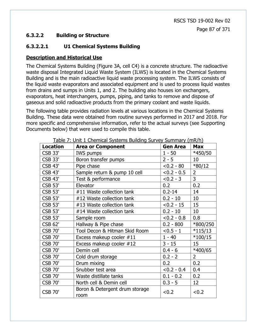
RSCS TSD 19-002 Rev 02
Page 87 of 371
6.3.2.2 Building or Structure
6.3.2.2.1 U1 Chemical Systems Building
Description and Historical Use
The Chemical Systems Building (Figure 3A, cell C4) is a concrete structure. The radioactive waste disposal Integrated Liquid Waste System (ILWS) is located in the Chemical Systems Building and is the main radioactive liquid waste processing system. The ILWS consists of the liquid waste evaporators and associated equipment and is used to process liquid wastes from drains and sumps in Units 1, and 2. The building also houses ion exchangers, evaporators, heat interchangers, pumps, piping, and tanks to remove and dispose of gaseous and solid radioactive products from the primary coolant and waste liquids.
The following table provides radiation levels at various locations in the Chemical Systems Building. These data were obtained from routine surveys performed in 2017 and 2018. For more specific and comprehensive information, refer to the actual surveys (see Supporting Documents below) that were used to compile this table.
Table 7: Unit 1 Chemical Systems Building Survey Summary (mR/h)
Location Area or Component Gen Area Max
CSB 33' IWS pumps 1 - 50 *450/50
CSB 33' Boron transfer pumps 2 - 5 10
CSB 43' Pipe chase <0.2 - 80 *80/12
CSB 43' Sample return & pump 10 cell <0.2 - 0.5 2
CSB 43' Test & performance <0.2 - 3 3
CSB 53' Elevator 0.2 0.2
CSB 53' #11 Waste collection tank 0.2-14 14
CSB 53' #12 Waste collection tank 0.2 - 10 10
CSB 53' #13 Waste collection tank <0.2 - 15 15
CSB 53' #14 Waste collection tank 0.2 - 10 10
CSB 53' Sample room <0.2 - 0.8 0.8
CSB 62' Hallway & Pipe chase 0.2 - 800 *800/250
CSB 70' Tool Decon & Hitman Skid Room <0.5 - 1 *115/13
CSB 70' Excess makeup cooler #11 1 - 40 *100/15
CSB 70' Excess makeup cooler #12 3 - 15 15
CSB 70' Demin cell 0.4 - 6 *400/65
CSB 70' Cold drum storage 0.2 - 2 2
CSB 70' Drum mixing 0.2 0.2
CSB 70' Snubber test area <0.2 - 0.4 0.4
CSB 70' Waste distillate tanks 0.1 - 0.2 0.2
CSB 70' North cell & Demin cell 0.3 - 5 12
CSB 70' Boron & Detergent drum storage room
<0.2 <0.2

RSCS TSD 19-002 Rev 02
Page 88 of 371
Location Area or Component Gen Area Max
CSB 70' Tool Decon & vacuum 0.4 - 0.8 *50/12
CSB 70' Snubber test area <0.2 <0.2
CSB 70' Radwaste process office <0.2 <0.2
CSB 70' Control room & east loading well <0.2 <0.2
CSB 70' North decon cell 0.2 - 0.4 0.4
CSB 70' FHF Section 3 <0.2 - 1 1
CSB 70' FHF Section 1 1.2 - 25 25
CSB 70' FHF Section 4 0.4 - 2 2
CSB 70' FHF Section 2 0.2 - 35 35
CSB 70' Bailing station 5 - 35 35
CSB 79' 6" Hot & cold cement mixer cubicles <0.2 <0.2
CSB 92' H/V duct room U1/105 <0.2 <0.2
CSB 92' H/V equipment room <0.2 <0.2
CSB 92' West roof <0.2 <0.2
CSB 92' East roof <0.2 <0.2
CSB 108' Elevator machine room <0.2 <0.2
CSB 108' East roof <0.2 - 0.2 0.2
CSB 108' Sphere vent room <0.2 <0.2
Note: *#/# is contact/30 cm
There are an additional forty-nine (49) rooms and areas that are not surveyed on a regular basis. The entrances to these rooms and areas have seals to prevent unauthorized access. The integrity of these seals is verified annually.
Known and Potential Contaminants
The ROCs are those categorized as Gammas, HTD&Betas, Tritium, and TRUs. The ROCs may be revised based upon more definitive data collected during site characterization activities.
Potentially Contaminated Media
• Building Materials • Concrete
• SSCs
Preliminary Classification
The Chemical Systems Building and all SSCs within it are preliminarily classified as a MARSSIM Class 1 structure due to the fact that the building has been an RCA during the operating years, has a high potential for containing residual radioactive material, and the presumption that if residual radioactivity is present, its concentration could exceed the acceptance criteria.

RSCS TSD 19-002 Rev 02
Page 89 of 371
Recommended Future Investigation Activities
• Direct measurements and contamination surveys of the building interior • Direct measurements and contamination surveys of the building exterior and roof • Radiological analysis of concrete samples to assess volumetric contamination
• Radiological analysis of samples of building sumps
Supporting Documents
SAO-132 Report 94-06 H-3 in U1 Sphere Foundation Sump.pdf U1 Chemical Systems Building surveys.pdf
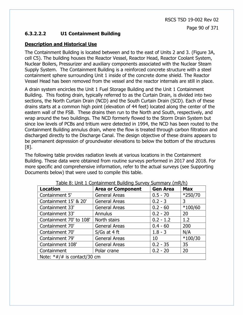
RSCS TSD 19-002 Rev 02
Page 90 of 371
6.3.2.2.2 U1 Containment Building
Description and Historical Use
The Containment Building is located between and to the east of Units 2 and 3. (Figure 3A, cell C5). The building houses the Reactor Vessel, Reactor Head, Reactor Coolant System, Nuclear Boilers, Pressurizer and auxiliary components associated with the Nuclear Steam Supply System. The Containment Building is a reinforced concrete structure with a steel containment sphere surrounding Unit 1 inside of the concrete dome shield. The Reactor Vessel Head has been removed from the vessel and the reactor internals are still in place.
A drain system encircles the Unit 1 Fuel Storage Building and the Unit 1 Containment Building. This footing drain, typically referred to as the Curtain Drain, is divided into two sections, the North Curtain Drain (NCD) and the South Curtain Drain (SCD). Each of these drains starts at a common high point (elevation of 44 feet) located along the center of the eastern wall of the FSB. These drains then run to the North and South, respectively, and wrap around the two buildings. The NCD formerly flowed to the Storm Drain System but since low levels of PCBs and tritium were detected in 1994, the NCD has been routed to the Containment Building annulus drain, where the flow is treated through carbon filtration and discharged directly to the Discharge Canal. The design objective of these drains appears to be permanent depression of groundwater elevations to below the bottom of the structures [8].
The following table provides radiation levels at various locations in the Containment Building. These data were obtained from routine surveys performed in 2017 and 2018. For more specific and comprehensive information, refer to the actual surveys (see Supporting Documents below) that were used to compile this table.
Table 8: Unit 1 Containment Building Survey Summary (mR/h)
Location Area or Component Gen Area Max
Containment 5' General Areas 0.5 - 70 *250/70
Containment 15' & 20' General Areas 0.2 - 3 3
Containment 33' General Areas 0.2 - 60 *100/60
Containment 33' Annulus 0.2 - 20 20
Containment 70' to 108' North stairs 0.2 - 1.2 1.2
Containment 70' General Areas 0.4 - 60 200
Containment 70' S/Gs at 4 ft 1.8 - 3 N/A
Containment 79' General Areas 10 *100/30
Containment 108' General Areas 0.2 - 35 35
Containment Polar crane 0.2 - 20 20
Note: *#/# is contact/30 cm

RSCS TSD 19-002 Rev 02
Page 91 of 371
Known and Potential Contaminants
The ROCs are those categorized as Gammas, HTD&Betas, Tritium, and TRUs. The ROCs may be revised based upon more definitive data collected during site characterization activities.
Potentially Contaminated Media
• Building Materials • Concrete
• Steel
• SSCs
Preliminary Classification
The Containment Building and all SSCs within it are preliminarily classified as a MARSSIM Class 1 structure due to the fact that the building has been an RCA throughout the operating years, has a high potential for containing residual radioactive material, and the presumption that if residual radioactivity is present, its concentration could exceed the acceptance criteria.
Recommended Future Investigation Activities
• Direct measurements and contamination surveys of the building interior • Direct measurements and contamination surveys of the building exterior • Radiological analysis of concrete samples to assess volumetric contamination
• Radiological analysis of samples of building sumps
Supporting Documents
NRC Inspection Report 50-247_92-16.pdf U1 Containment Building surveys.pdf Unit 1 Safety Analysis Report.pdf

RSCS TSD 19-002 Rev 02
Page 92 of 371
6.3.2.2.3 U1 Contractor Fabrication Shop
Description and Historical Use
The Unit 1 Contractor Fabrication Shop (Figure 3A, cell C3) provides a place for storage of equipment and parts and a space for maintenance and fabrication activities. This facility was used for various trades such as pipe-fitting, sheet metal and insulation.
Radioactive material was not used or stored in this building, but because of its proximity to the power block, there is the potential that trace levels of contamination may have accumulated in this building, primarily from airborne deposition on the roof and from the routine movement of personnel and equipment between buildings.
Known and Potential Contaminants
The ROCs are those categorized as Gammas and HTD&Betas. The ROCs may be revised based upon more definitive data collected during site characterization activities.
Potentially Contaminated Media
• Building Surfaces
Preliminary Classification
The Contractor Fabrication Shop is preliminarily classified as a MARSSIM Class 3 structure based on the discussion above, and the presumption that if residual radioactivity is present, its concentration will not exceed a small fraction of the acceptance criteria.
Recommended Future Investigation Activities
• Direct measurements and contamination surveys of the building interior
• Direct measurements and contamination surveys of the building exterior and roof

RSCS TSD 19-002 Rev 02
Page 93 of 371
6.3.2.2.4 U1 Fuel Storage Building
Description and Historical Use
The Fuel Storage Building (Figure 3A, cell C5) is a concrete structure. Located in the Fuel Storage Building are the spent fuel pools, cooling, filtration, and demineralization systems, fuel handling equipment, building ventilation and filtration systems and necessary power and control systems. The Unit 1 fuel pool complex system consists of six interconnected pools; the West Pool and East Pool, a Failed Fuel Pool, Disassembly Pool, a Cask Loading Pool, and a Transfer Pool.
The Unit 1 Reactor was defueled in January 1976. A total of 160 fuel elements were stored in the West Pool until 2008, when they were transferred to the on-site Independent Spent Fuel Storage Installation (ISFSI). The fuel racks remain in the fuel pools.
Con Edison had identified leakage from the West Fuel Pool in the 1990’s and was managing the leakage by collecting it from a reconfigured footing drain that surrounds the fuel storage building.
Known and Potential Contaminants
The ROCs are those categorized as Gammas, HTD&Betas, Tritium, and TRUs. The ROCs may be revised based upon more definitive data collected during site characterization activities.
Potentially Contaminated Media
• Building Materials
• Concrete • Steel
• SSCs
Preliminary Classification
The Fuel Storage Building and all SSCs within it are preliminarily classified as a MARSSIM Class 1 structure due to the fact that the building has been an RCA throughout the operating years, has a high potential for containing residual radioactive material, and the presumption that if residual radioactivity is present, its concentration could exceed the acceptance criteria.
Recommended Future Investigation Activities
• Direct measurements and contamination surveys of the building interior • Direct measurements and contamination surveys of the building exterior and roof • Radiological analysis of concrete samples to assess volumetric contamination
• Radiological analysis of samples of building sumps
Supporting Documents
ABS Consulting SFP Concrete report 1105145 R-002 July 2002.pdf May132008InsepctionReportML081340425 (1).pdf

RSCS TSD 19-002 Rev 02
Page 94 of 371
NRC Inspection Report 50-247_92-16.pdf NRC Inspection Report 94-80.pdf SAO-132 Report 94-06 H-3 in U1 Sphere Foundation Sump.pdf Unit 1 Safety Analysis Report.pdf

RSCS TSD 19-002 Rev 02
Page 95 of 371
6.3.2.2.5 U1 Monitor House and Utility Tunnel
Description and Historical Use
The Unit 1 Monitor House (Figure 3A, cell D4) is a small brick building at the eastern terminus of the underground Unit 1 Utility Tunnel that provides access to the Utility Tunnel. The Utility Tunnel is a seismic Class III structure. The tunnel provides shelter and protection for the city water supply piping used for auxiliary feedwater backup water and other miscellaneous functions. The Utility Tunnel is a rectangular reinforced concrete structure founded on rock. The western portion of the Utility Tunnel also contain the Unit 1/2 radioactive waste discharge pipe that transports waste to the Discharge Canal.
It has been noted in several Condition Reports that the Utility Tunnel is a posted RCA and has loose surface contamination throughout. It was also noted that flaking paint in the tunnel also contains radioactive material.
Known and Potential Contaminants
The ROCs are those categorized as Gammas and HTD&Betas. The ROCs may be revised based upon more definitive data collected during site characterization activities.
Potentially Contaminated Media
• Building Surfaces
Preliminary Classification
The Monitor House and Utility Tunnel are preliminarily classified as a MARSSIM Class 2 structure based on the discussion above, and the presumption that if residual radioactivity is present, its concentration is not likely to exceed the acceptance criteria.
Recommended Future Investigation Activities
• Direct measurements and contamination surveys of the building interior
• Direct measurements and contamination surveys of the building exterior and roof
Supporting Documents
CR-IP2-2000-09854, Rad Effluents Audit 00-03-F.pdf CR-IP2-2001-04352, Utility Tunnel Contaminated.pdf CR-IP2-2007-02551, Loose surface Contamination Found in U1 Utility Tunnel.pdf

RSCS TSD 19-002 Rev 02
Page 96 of 371
6.3.2.2.6 U1 Gas Turbine 1 Generator Building
Description and Historical Use
The Unit 1 Gas Turbine Generator formerly provided emergency electrical power to Unit 1 and has been retired. The location of the Unit 1 Gas Turbine 1 Generator Building is shown in Figure 3A, cell B4.
As discussed in Subsection 4.2.2.1, oil seepage was identified in a portion of the underground Utility Tunnel located between the U1 Turbine Building and the GT 1 Generator Building. The area above this section of the tunnel contains the fill manifold for the GT1 fuel oil storage tanks and is also where 55-gallon drums of oil had been stored previously [13].
Two soil borings were drilled in the area of the storage tank fill manifold and Utility Tunnel in March 2000, during a Phase 2 environmental site assessment of Units 1 and 2. Petroleum constituents were detected in soil samples collected from the soil borings and groundwater sampled from monitoring wells constructed in the soil borings [14].
Removal of the oily soil was not attempted because the oil was determined not likely to migrate as it is probably heavy No. 6 fuel oil, and because of the presence of subsurface barriers consisting of a utility tunnel wall to the south, the Discharge Canal wall to the west, a rock outcrop to the east and the Unit 1 Turbine Building foundation to the north. In addition, subsurface utilities in the area which are nuclear safety-related preclude the safe excavation of contaminated soil while the plant remains operational. Instead, a semi-annual program of groundwater monitoring, removal of free-phase oil from surrounding monitoring wells (if present) and reporting to the NYSDEC was initiated [15].
Known and Potential Contaminants
The ROCs are those categorized as Gammas and HTD&Betas. The ROCs may be revised based upon more definitive data collected during site characterization activities.
Potentially Contaminated Media
• Building Materials
• Concrete • Steel
• SSCs
Preliminary Classification
Because contaminated soil and groundwater was confirmed by sampling in 2000 and was left in place, residual contamination may remain. The area adjacent to the Unit 1 Gas Turbine Generator Building where the fill manifold for the fuel oil tanks is located is assigned a preliminary classification of NR Class 1.

RSCS TSD 19-002 Rev 02
Page 97 of 371
Recommended Future Investigation Activities
Collect additional samples of soil and groundwater in the area of interest and analyze the samples for Petroleum Constituents to determine the current environmental conditions in the area.

RSCS TSD 19-002 Rev 02
Page 98 of 371
6.3.2.2.7 U1 Nuclear Service Building
Description and Historical Use
The Nuclear Service Building is adjacent to but separated from the Unit 1 containment structure. The Nuclear Service Building (Figure 3A, cell B5) is a multi-story reinforced concrete structure that provided equipment and services to support reactor operations. The building contains air compressors, fans and pumps, Reactor Building exhaust ventilation, laundry and lavatory facilities, first aid room, Radiochemistry Laboratory, sample rooms, HP count room and lockers. The building also currently houses retired Unit 1 equipment.
The following table provides radiation levels at various locations in the Nuclear Service Building. These data were obtained from routine surveys performed in 2018. For more specific and comprehensive information, refer to the actual surveys (see Supporting Documents below) that were used to compile this table.
Table 9: Unit 1 Nuclear Service Building Survey Summary (mR/h)
Location Area or Component Gen Area Max
NSB 33' Contaminated waste drain 0.6 - 4 4
NSB 33' Eddie current room <0.2 <0.2
NSB 33' Rad material storage area <0.2 <0.2
NSB 43' Amplifier room <0.2 <0.2
NSB 53' Radiochem Lab 0.1 - 1.8 *4.5/1.8
NSB 53' RCL Sample cell #3 1 - 2 *10/5
NSB 53' RP count room <0.2 <0.2
NSB 53' RP storage area/room <0.2 <0.2
NSB 62' Pipe chase <0.2 <0.2
NSB 72' Decon room/Equip room <0.2 <0.2
NSB 72' Hallway <0.2 <0.2
NSB 84' Hallway <0.2 <0.2
NSB 84' Plant vent room <0.2 <0.2
NSB 100' HV Refrig room <0.2 <0.2
NSB 115' Roof <0.2 <0.2
Note: *#/# is contact/30 cm
Known and Potential Contaminants
The ROCs are those categorized as Gammas, HTD&Betas, Tritium, and TRUs. The ROCs may be revised based upon more definitive data collected during site characterization activities.
Potentially Contaminated Media
• Building Materials

RSCS TSD 19-002 Rev 02
Page 99 of 371
• Concrete
• SSCs
Preliminary Classification
The Nuclear Service Building and all SSCs within it are preliminarily classified as a MARSSIM Class 1 structure due to the fact that the building has been an RCA during the operating years, has a high potential for containing residual radioactive material, and the presumption that if residual radioactivity is present, its concentration could exceed the acceptance criteria.
Recommended Future Investigation Activities
• Direct measurements and contamination surveys of the building interior
• Direct measurements and contamination surveys of the building exterior and roof • Radiological analysis of concrete samples to assess volumetric contamination
• Radiological analysis of samples of building sumps
Supporting Documents
U1 Nuclear Service Building surveys.pdf
RSCS TSD 19-002 Rev 02
Page 100 of 371
6.3.2.2.8 U1 Screenwell House
Description and Historical Use
The Screenwell House is a concrete structure and is the location of the Unit 1 water intake. Components in the Screenwell House include the trash racks, traveling screens and pumps for the river water, wash water, and fire protection systems. The Screenwell House also provides protection for alternate safe shutdown system (ASSS) equipment and currently houses support equipment for Unit 2. The building is located at the west end of the Protected Area, on the Hudson River (Figure 3A, cell A5).
Radioactive material was not used or stored in this building, but because of its proximity to the power block, there is the potential that trace levels of contamination may have accumulated in this building, primarily from airborne deposition on the roof and from the routine movement of personnel and equipment between buildings.
Known and Potential Contaminants
The ROCs are those categorized as Gammas and HTD&Betas. The ROCs may be revised based upon more definitive data collected during site characterization activities.
Potentially Contaminated Media
• Building Surfaces
Preliminary Classification
The Screenwell House is preliminarily classified as a MARSSIM Class 3 structure based on the discussion above, and the presumption that if residual radioactivity is present, its concentration will not exceed a small fraction of the acceptance criteria.
Recommended Future Investigation Activities
• Direct measurements and contamination surveys of the building interior
• Direct measurements and contamination surveys of the building exterior and roof

RSCS TSD 19-002 Rev 02
Page 101 of 371
6.3.2.2.9 U1 Superheater & Administration Building
Description and Historical Use
The Superheater & Administration Building (S&AB) (Figure 3A, cell B5) is adjacent to but physically separated from the Unit 1 Control Building. The superheater stack is located on top of the Unit 1 S&AB. The structure houses the safety-related battery room No. 23. The construction of the S&AB consists of steel framing on a reinforced concrete mat. The floors are metal grating and reinforced concrete slabs. The exterior walls are masonry and metal siding.
The water treatment plant is located in the S&AB. The water treatment plant was retired in place in 2000 and is no longer the main supply of demineralized water to the Indian Point Energy Center.
The auxiliary steam system, consisting of oil-fired boilers located in the S&AB, supplies steam to Units 1, 2, and 3 for auxiliary operation and for building heating.
As part of the increased utilization of Unit 1 facilities in support of the overall site goal of efficient power production, portions of the conventional (non-nuclear) side of the facility such as the Turbine Generator, oil fired superheaters and associated components have been removed to allow establishment of administrative offices, emergency response facilities and equipment laydown areas. The principle Alternate Safe Shutdown System power supply and associated switch gear installed in support of Unit 2 in response to NUREG -0737 has also been located in Unit 1.
The S&AB also currently houses retired Unit 1 secondary side support equipment and is the location of the Technical Support Center (TSC) for the site.
On the 15’ elevation of the S&AB, there is a Containment Spray Sump that would provide a source of water for the Containment Spray System in the event of an emergency. In 1999, an increasing trend was noted in the amount of Cs-137 (5E-07 mCi/ml) in the water of the sump. After evaluating the potential sources of this contamination, the radioactivity was attributed to steam generator blowdown. This sump had been fenced off and is considered an RCA.
Known and Potential Contaminants
The ROCs are those categorized as Gammas and HTD&Betas. The ROCs may be revised based upon more definitive data collected during site characterization activities.
Potentially Contaminated Media
• Building Surfaces
Preliminary Classification
The Superheater & Administrative Building is preliminarily classified as a MARSSIM Class 3 structure based on the discussion above, and the presumption that if residual radioactivity is present, its concentration will not exceed a small fraction of the acceptance criteria.

RSCS TSD 19-002 Rev 02
Page 102 of 371
Recommended Future Investigation Activities
• Direct measurements and contamination surveys of the building interior • Direct measurements and contamination surveys of the building exterior and roof
• Radiological analysis of samples of building sumps

RSCS TSD 19-002 Rev 02
Page 103 of 371
6.3.2.2.10 U1 Turbine Generator Building
Description and Historical Use
The Turbine Generator Building and heater bays are attached to the Superheater & Administration Building (Figure 3A, cell B5). The Turbine Generator Building with its auxiliary bays, houses the turbine generator and associated auxiliaries, the Condensate and Feedwater Systems, switchgear, the Turbine Generator Building crane, and other auxiliary equipment. The Turbine Generator Building also houses the station blackout/Appendix R diesel and two fire water pumps. The Appendix R diesel is located on the turbine pedestal.
The Turbine Generator Building and heater bays are constructed of heavy structural steel framing with steel supported concrete slabs forming the floor area. The building’s exterior face is constructed of metal-sandwich panels and concrete brick.
The saturated secondary steam produced in the steam generators was superheated in two oil-fired superheaters and then used to drive a three cylinder, tandem-compound, double-flow high pressure and double-flow low pressure condensing turbine generator. The heat removed from the condensing steam was transferred to the circulating water system and then discharged to the Hudson River.
The Turbine Generator Building is currently being re-used as office space and a machine shop. In addition, the Turbine Generator Building houses a 13.8 kV transformer which provides backup offsite power for Units 2 and 3. Radioactive material was not used or stored in this building, but because of its location in the power block, there is the potential that trace levels of contamination may have accumulated in this building, primarily from airborne deposition on the roof and from the routine movement of personnel and equipment between buildings.
Known and Potential Contaminants
The ROCs are those categorized as Gammas and HTD&Betas. The ROCs may be revised based upon more definitive data collected during site characterization activities.
Potentially Contaminated Media
• Building Materials • Concrete • Steel
• Roofing Materials
• SSCs
Preliminary Classification
The Turbine Generator Building is preliminarily classified as a MARSSIM Class 3 structure based on the discussion above, and the presumption that if residual radioactivity is present, its concentration will not exceed a small fraction of the acceptance criteria.

RSCS TSD 19-002 Rev 02
Page 104 of 371
Recommended Future Investigation Activities
• Direct measurements and contamination surveys of the building interior
• Direct measurements and contamination surveys of the building exterior and roof
RSCS TSD 19-002 Rev 02
Page 105 of 371
6.3.2.3 Exterior Area
6.3.2.3.1 U1 Former Septic Leach Field
Description and Historical Use
In 1960, during construction of the Unit 1 plant, a Sewage Treatment Plant and sanitary disposal system consisting of a septic tank and surface sand filters was constructed to service plant facilities. This facility was constructed approximately 1000 feet south of the plant structures in an area not anticipated to be needed for future construction (Figure 3A, cell A2). However, during construction of service facilities for the Unit 3 plant, it became necessary to remove this old sanitary disposal system in 1979 to allow for road and storm drainage construction activities to progress. The Sewage Treatment Plant was retired in place and a pumping station was constructed to allow pumping of sewage from the station to the Buchanan sewage treatment plant [39].
In early 1979 a sampling campaign was executed in the sand filter beds. Core borings were taken from each of the 4 sand filters to a depth of approximately 8 feet. These cores were obtained in 2-foot lengths. The majority of the activity detected was concentrated in the top 4 feet of the sand filter beds. The Cs-137 concentration in the top 4 feet ranged from 0.5 pCi/g to 533 pCi/g. The Cs-134 concentration in the top 4 feet ranged from <0.1 to 57.9 pCi/g. The Co-60 concentration in the top 4 feet ranged from 0.1 pCi/g to 119 pCi/g. The total amount of activity present in the 3,000 cubic meters of material was estimated to be less than 100 millicuries.
After much legal and regulatory review and discussions, it was decided to store the excavated material on-site. The best way to store the material was to remove it and relocate it to a containment cell excavated at the southern end of the property. The containment cell was lined and capped with a bentonite clay material to minimize infiltration of ground water which could cause spreading of the contamination. It was determined that only approximately the top four to five feet of material was to be moved to facilitate construction in the original area of the septic leach fields. This decision reduced the volume of material that had to be considered for physical removal and re-location.
Known and Potential Contaminants
The ROCs are those categorized as Gammas, HTD&Betas, and Tritium. The ROCs may be revised based upon more definitive data collected during site characterization activities.
Potentially Contaminated Media
• Soil
Preliminary Classification
The Septic Field is preliminarily classified as a MARSSIM Class 1 area based on the discussion above, and the presumption that if residual radioactivity is present, its concentration could exceed the acceptance criteria.

RSCS TSD 19-002 Rev 02
Page 106 of 371
Recommended Future Investigation Activities
• Radiological analysis of soil samples taken at a depth starting at approximately four feet below the ground surface in a systematic fashion.
Supporting Documents
Mod 79-03-077 Relocation of the Septic field.pdf

RSCS TSD 19-002 Rev 02
Page 107 of 371
Unit 2 Impacts
6.4.1 Non-Radiological Impacts
6.4.1.1 Building or Structure
6.4.1.1.1 U2 Emergency Diesel Generator Building
Description and Historical Use
The Unit 2 Emergency Diesel Generator Building (Figure 3A, cell B5) contains three Emergency Diesel Generators and three 175-gallon steel above ground storage tanks (Day tanks) containing diesel fuel. The main fuel supply for the generators is stored in three 7,700-gallon steel underground storage tanks equipped with level alarms. No record of a release of hazardous material in this building has been found.
Known and Potential Contaminants
The non-radiological contaminants are Diesel Fuel and Lubricating Oil.
Potentially Contaminated Media
• Building Materials (Floor)
Preliminary Classification
Because the diesel fuel day tanks are in an area that is bermed and contained within the Emergency Diesel Generator Building it is not likely that releases that may have occurred in the building have caused gross contamination of soil or groundwater. However, a relatively large volume of oil is potentially stored. Therefore, this building is assigned a preliminary classification of NR Isolated.
Recommended Future Investigation Activities
Inspect the concrete floor for indications of staining, cracks or openings that could release the Potential Contaminants to the environment.

RSCS TSD 19-002 Rev 02
Page 108 of 371
6.4.1.1.2 U2 Intake Structure
Description and Historical Use
The Unit 2 Intake Structure (Figure 3A,Cells A5 to A6) is the location of the station water intake components including the trash racks, traveling screens and pumps for the circulation water, service water, residual heat removal and fire protection systems.
Sodium hypochlorite is stored in two fiberglass above ground storage tanks and is injected into the circulating water to limit biofouling of the condenser and into the service water to limit biofouling of heat exchangers. No record of a release of hazardous material from the Intake Structure has been found.
Known and Potential Contaminants
The non-radiological contaminants are Lubricating Oil, RCRA Metals, and Sodium Hypochlorite.
Potentially Contaminated Media
• Soil
• Groundwater
Preliminary Classification
The Intake Structure equipment is not contained within a building and there is the potential that incidental releases of Lubricating Oil could be released to the environment. The Intake structure is assigned a preliminary classification of NR Class 3.
Recommended Future Investigation Activities
Inspect the concrete floor for indications of staining, cracks or openings that could release the Potential Contaminants to the environment.

RSCS TSD 19-002 Rev 02
Page 109 of 371
6.4.1.1.3 U2 Turbine Generator Building
Description and Historical Use
The Unit 2 Turbine Generator Building (Figure 3A,Cells B5 to B6) houses the Unit 2 Turbine Generator and associated auxiliaries, the Condenser, Condensate and Feedwater Systems, switchgear, the Turbine Building crane, and other auxiliary equipment. The Turbine Building is a rigid steel and concrete structure.
Structural steel members in the building are assumed to be coated with lead-based paint. Various components such as pump and valve gaskets and pipe wrap may contain asbestos. Other components such as electrical switches, relays, thermostats and gauges may contain mercury.
As discussed in Subsection 4.2.2.1 a bushing failure and fire in the Unit 21 Main Transformer in 2010 resulted in release of oil to soil and the Discharge Canal. The deluge system that automatically engaged to extinguish the fire released a large volume of water and fire-suppression foam. As a result, water and transformer oil overflowed the berm containing the transformer. The released oil infiltrated the local soil and apparently accumulated in pockets against the downgradient Turbine Building east foundation. Groundwater monitoring wells were installed to investigate and remove the accessible oil.
Known and Potential Contaminants
The non-radiological contaminants are Asbestos, Lead, Lubricating Oil, Waste Oil, RCRA Metals, and Dielectric Oil.
Potentially Contaminated Media
• Soil • Groundwater • Lead Paint • Mercury-Containing Components
• Pipe Insulation
• Sumps
Preliminary Classification
Because of the known release of Dielectric Oil that accumulated at the Unit 2 Turbine Generator Building foundation, a preliminary classification of NR Class 1 is assigned to the building.
Recommended Future Investigation Activities
Collect additional samples of soil and groundwater in the area of interest and analyze the samples for the Potential Contaminants.
Supporting Documents
CR-IP2-2010-06803, main transformer explosion.pdf Letter to Joyce Jiudice regarding Order on Consent and Associated Schedu....pdf

RSCS TSD 19-002 Rev 02
Page 110 of 371
Spill No.1008306, 100 gallons transformer oil to soil & surface water, 11-8-2010.pdf

RSCS TSD 19-002 Rev 02
Page 111 of 371
6.4.1.2 Chemical and Drum Storage Areas
6.4.1.2.1 U2 Hazardous Waste Storage Bin
Description and Historical Use
Because Units 2 and 3 have separate permits to generate hazardous waste in accordance with provisions of the U.S. Resource Conservation and Recovery Act (RCRA), each Unit must store their hazardous waste separately. As a Large Quantity Generator, Unit 2 stores no more than 1,000 kilograms per month in its Hazardous Waste Storage Bin, located in the parking lot near the northwest corner of the Maintenance Training Facility (Figure 4, Cell C3). No record of a release of hazardous material in this building has been found.
Known and Potential Contaminants
The non-radiological contaminants are Acids-Bases, Batteries, Lead, Mercury, Spent Solvents, and RCRA Metals. Because the Unit 2 hazardous wastes are stored within an enclosed structure, if handled properly these materials are not expected to pose a risk of contamination to environmental media such as soil or groundwater.
Potentially Contaminated Media
• Building Materials (Floor)
Preliminary Classification
The Unit 2 Hazardous Waste Storage Bin is assigned a preliminary classification of NR Isolated.
Recommended Future Investigation Activities
Inspect the floor of the Unit 2 Hazardous Waste Storage Bin for indications of staining, cracks or openings that could release the Potential Contaminants to the environment.

RSCS TSD 19-002 Rev 02
Page 112 of 371
6.4.1.2.2 U2 Oil Storage Cabinets
Description and Historical Use
Four cabinets containing a total of up to 1,200 gallons of virgin diesel fuel and lubricating oil in various containers are located west of the Unit 1 Turbine Generator Building (Figure 4, Cell A5). No record of a release of hazardous material from these cabinets has been found.
Known and Potential Contaminants
The non-radiological contaminants are Diesel Fuel and Lubricating Oil. Because the Unit 2 Oil Storage Cabinets are enclosed structures, if handled properly these materials are not expected to pose a risk of contamination to environmental media such as soil or groundwater.
Potentially Contaminated Media
• Building Materials (Floor)
Preliminary Classification
The Unit 2 Oil Storage Cabinets are assigned a preliminary classification of NR Isolated.
Recommended Future Investigation Activities
Inspect the floor of the Oil Storage Cabinets for indications of staining, cracks or openings that could release the Potential Contaminants to the environment.

RSCS TSD 19-002 Rev 02
Page 113 of 371
Chemical and Drum Storage Areas Supporting Documents
EN-EV-106__007.pdf IPEC Haz. Waste Inventory.pdf

RSCS TSD 19-002 Rev 02
Page 114 of 371
6.4.1.3 Exterior Area
6.4.1.3.1 U2 Transformer Yard
Description and Historical Use
The Unit 2 Transformer Yard (Figure 3A, Cell B5) contains the 21 and 22 Main Transformers, Station Auxiliary Transformer and Unit Auxiliary Transformer. As discussed in Subsection 4.2.2.1 plant personnel have reported observing visible staining of bluestone and a sheen on surface water that collects in the U2 Transformer Yard during periods of heavy precipitation [13] [14]. Con Edison managed the condition by removing visibly stained soil and deploying sorbent pigs around the area storm drain during periods when surface drainage accumulated [15].
A bushing failure and fire in the Unit 21 Main Transformer in 2010 resulted in release of oil to soil and the Discharge Canal. (CR-IP2-2010-06803; NYSDEC Spill No. 1008306) [16] [17] [19].
The deluge system that automatically engaged to extinguish the fire released a large volume of water and fire-suppression foam. As a result, water and transformer oil overflowed the berm containing the transformer. The released oil infiltrated the local soil and apparently accumulated in pockets against the downgradient Turbine Building east foundation. Groundwater monitoring wells were installed to investigate and remove the accessible oil. The contaminated trap rock within the transformer berm was removed, an impermeable liner was applied to the berm floor and walls, clean trap rock was placed in the berm and a replacement 21 Main Transformer was installed.
Known and Potential Contaminants
The non-radiological contaminants are Dielectric Oil, RCRA Metals, Petroleum Constituents, and PCB-Containing Dielectric Oil.
Potentially Contaminated Media
• Soil • Groundwater • Concrete
• Trap Rock
Preliminary Classification
The Unit 2 Transformer Yard is assigned a preliminary classification of NR Class 1.
Recommended Future Investigation Activities
Collect additional samples of soil and groundwater in the area of interest and analyze the samples for the Potential Contaminants.
Supporting Documents
CR-IP2-2000-01957, hydraulic oil spill near 95' Maintenance Outage Building.pdf

RSCS TSD 19-002 Rev 02
Page 115 of 371
CR-IP2-2006-04701, Diesel oil in manholes and pipe segments in transformer yard.pdf Draft Letter to NYSDEC re 4 AOCs at IPEC.pdf Phase I ESA Units 1&2 Jan 2000.pdf Phase II ESA Units 1&2 Mar 2000.pdf

RSCS TSD 19-002 Rev 02
Page 116 of 371
6.4.1.4 Oil-Filled Mechanical Equipment
6.4.1.4.1 U2 Appendix R Diesel Generator
Description and Historical Use
The Unit 2 Appendix R Diesel Generator is located at the south end of the Unit 1 Turbine Generator Building (Figure 4, Cell A5) and contains approximately 100 gallons of lubricating oil. A day tank containing approximately 800 gallons of diesel fuel for the generator is located near the generator. This day tank is discussed in Section 0. No record of a release of hazardous material from the Unit 2 Appendix R Diesel Generator enclosure has been found.
Known and Potential Contaminants
The non-radiological contaminants are Lubricating Oil, RCRA Metals, and Diesel Fuel. Because the generator is located within the Unit 1 Turbine Generator Building, if handled properly these materials are not expected to pose a risk of contamination to environmental media such as soil or groundwater.
Potentially Contaminated Media
• Building Materials (Floor)
Preliminary Classification
Because the Unit 2 Appendix R Diesel Generator is located within the Unit 1 Turbine Generator Building it is not likely that releases of Diesel Fuel or Lubricating Oil that may have occurred from the Generator have caused gross contamination of soil or groundwater. The Generator is assigned a preliminary classification of NR Isolated.
Recommended Future Investigation Activities
Inspect the floor of the Unit 2 Appendix R Diesel Generator enclosure for indications of staining, cracks or openings that could release the Potential Contaminants to the environment.

RSCS TSD 19-002 Rev 02
Page 117 of 371
6.4.1.4.2 U2 Circulation Water Pump Motors
Description and Historical Use
The Unit 2 Circulation Water Pumps are located in the Unit 2 Intake Structure (Figure 3A, Cells A5 to A6), downstream from the trash rack and traveling screens. Each pump motor contains approximately 100 gallons of lubricating oil. No record of a release of lubricating oil from the pump motors has been found.
Known and Potential Contaminants
The non-radiological contaminants are Lubricating Oil and RCRA Metals. If handled properly, these materials are not expected to pose a risk of contamination to environmental media such as soil or groundwater.
Potentially Contaminated Media
• Building Materials (Floor)
Preliminary Classification
Based on their location at the Intake Structure it is not likely that releases of Lubricating Oil that may have occurred from the Pump Motors have caused gross contamination of soil or groundwater. The Circulating Water Pump Motors are assigned a preliminary classification of NR Isolated.
Recommended Future Investigation Activities
Inspect the area of the Circulation Water Pump Motors for indications of staining, cracks or openings that could release the Potential Contaminants to the environment.

RSCS TSD 19-002 Rev 02
Page 118 of 371
6.4.1.4.3 U2 Condensate Pump Motors
Description and Historical Use
The Unit 2 Condensate Pumps are located in the Unit 2 Turbine Generator Building (Figure 3A, Cells B5 to B6). All drains from the Turbine Generator Building flow to the Chemical Services Building for treatment and to ensure that no oil or unmonitored radioactivity leaves the building. The pump motors contain a total of approximately 300 gallons of lubricating oil. No record of a release of lubricating oil from the pump motors has been found.
Known and Potential Contaminants
The non-radiological contaminants are Lubricating Oil and RCRA Metals. If handled properly, these materials are not expected to pose a risk of contamination to environmental media such as soil or groundwater.
Potentially Contaminated Media
• Building Materials (Floor)
Preliminary Classification
Based on their location within the Unit 2 Turbine Generator Building it is not likely that releases of Lubricating Oil that may have occurred from the Pump Motors have caused gross contamination of soil or groundwater. The Condensate Pump Motors are assigned a preliminary classification of NR Isolated.
Recommended Future Investigation Activities
Inspect the area of the Condensate Pump Motors for indications of staining, cracks or openings that could release the Potential Contaminants to the environment.

RSCS TSD 19-002 Rev 02
Page 119 of 371
6.4.1.4.4 U2 Diesel Fire Pump Motor
Description and Historical Use
The Unit 2 Diesel Fire Pump is located in a building next to the Unit 2 Fire Water Storage Tank (Figure 3A, Cell C5). The pump motor contains approximately 100 gallons of lubricating oil. A tank with a capacity of 275 gallons is located in the building and stores diesel fuel for the Diesel Fire Pump. This storage tank is discussed in Section 6.4.1.5.16. No record of a release of lubricating oil from the pump motor has been found.
Known and Potential Contaminants
The non-radiological contaminants are Lubricating Oil, RCRA Metals, and Diesel Fuel. If handled properly, these materials are not expected to pose a risk of contamination to environmental media such as soil or groundwater.
Potentially Contaminated Media
• Building Materials (Floor)
Preliminary Classification
Based on its location within a small building it is not likely that releases of Diesel Fuel or Lubricating Oil that may have occurred from the Pump Motor has caused gross contamination of soil or groundwater. A preliminary classification of NR Isolated is assigned to the Unit 2 Diesel Fire Pump Motor.
Recommended Future Investigation Activities
Inspect the area of the Diesel Fire Pump Motor for indications of staining, cracks or openings that could release the Potential Contaminants to the environment.

RSCS TSD 19-002 Rev 02
Page 120 of 371
6.4.1.4.5 U2 Emergency Diesel Generators
Description and Historical Use
The Unit 2 Emergency Diesel Generators are located in the Unit 2 Emergency Diesel Generator Building (Figure 3A, Cell B5). Each of the three generators contain approximately 150 gallons of lubricating oil. No record of a release of lubricating oil from the Unit 2 Emergency Diesel Generators has been found.
Known and Potential Contaminants
The non-radiological contaminants are Diesel Fuel, Lubricating Oil, and RCRA Metals. If handled properly, these materials are not expected to pose a risk of contamination to environmental media such as soil or groundwater.
Potentially Contaminated Media
• Building Materials (Floor)
Preliminary Classification
Based on their location within the Unit 2 Emergency Diesel Generator Building it is not likely that releases of Diesel Fuel or Lubricating Oil that may have occurred from the Generators has caused gross contamination of soil or groundwater. The Emergency Diesel Generators are assigned a preliminary classification of NR Isolated.
Recommended Future Investigation Activities
Inspect the area of the Unit 2 Emergency Diesel Generators for indications of staining, cracks or openings that could release the Potential Contaminants to the environment.

RSCS TSD 19-002 Rev 02
Page 121 of 371
6.4.1.4.6 U2 Technical Support Center Emergency Diesel Generator
Description and Historical Use
The Unit 2 Technical Support Center (TSC) Emergency Diesel Generator is located in the Superheater and Administration Building (Figure 3A, Cell B5). The generator contains approximately 100 gallons of diesel fuel and lubricating oil. Battery banks to supply back up power to the TSC are also located in the Superheater and Administration Building. No record of a release of diesel fuel or lubricating oil from the Unit 2 Technical Support Center Emergency Diesel Generator has been found.
Known and Potential Contaminants
The non-radiological contaminants are Diesel Fuel, Lubricating Oil, and RCRA Metals. If handled properly, these materials are not expected to pose a risk of contamination to environmental media such as soil or groundwater.
Potentially Contaminated Media
• Building Materials (Floor)
Preliminary Classification
Based on its location within the Superheater and Administration Building it is not likely that releases of Diesel Fuel or Lubricating Oil that may have occurred from the generator has caused gross contamination of soil or groundwater. The Unit 2 Technical Support Center Emergency Diesel Generator is assigned a preliminary classification of NR Isolated.
Recommended Future Investigation Activities
Inspect the area of the Unit 2 Technical Support Center Emergency Diesel Generator for indications of staining, cracks or openings that could release the Potential Contaminants to the environment.

RSCS TSD 19-002 Rev 02
Page 122 of 371
6.4.1.5 Storage Tanks
6.4.1.5.1 U2 21 Emergency Diesel Generator Day Tank 21FODT
Description and Historical Use
The Unit 2 21 Emergency Diesel Generator Day Tank is a 175-gallon steel above ground tank located in the Unit 2 Emergency Diesel Generator Building (Figure 4, Cell B5). No record of a release of diesel fuel from the Unit 2 21 Emergency Diesel Generator Day Tank has been found.
Known and Potential Contaminants
The non-radiological contaminant is Diesel Fuel. If handled properly, this material is not expected to pose a risk of contamination to environmental media such as soil or groundwater.
Potentially Contaminated Media
• Building Materials (Floor)
Preliminary Classification
Because the Unit 2 21 Emergency Diesel Generators Day Tank is located inside the Unit 2 Emergency Diesel Generator Building with secondary containment, a release of diesel fuel from the tank is unlikely to result in gross contamination of soil or groundwater. The area of this AST is assigned a preliminary classification of NR Isolated.
Recommended Future Investigation Activities
Inspect the area of the Unit 2 21 Emergency Diesel Generator Day Tank for indications of staining, cracks or openings that could release the Potential Contaminants to the environment.

RSCS TSD 19-002 Rev 02
Page 123 of 371
6.4.1.5.2 U2 21 Emergency Diesel Generator Storage Tank 21FOST
Description and Historical Use
The Unit 2 21 Emergency Diesel Generator Storage Tank is a 7,700-gallon steel underground tank equipped with a level alarm and located adjacent to the Unit 2 Emergency Diesel Generator Building (Figure 4, Cell B5). No record of a release of diesel fuel from the Unit 2 21 Emergency Diesel Generator Storage Tank has been found.
Known and Potential Contaminants
The non-radiological contaminant is Diesel Fuel.
Potentially Contaminated Media
• Soil
• Groundwater
Preliminary Classification
Because the Unit 2 21 Emergency Diesel Generator Storage Tank is an underground tank storing a large volume of diesel fuel that could be released due to undetected leakage or overfilling during deliveries, a preliminary classification of NR Class 1 is assigned to the tank.
Recommended Future Investigation Activities
• Inspect the area surrounding the fill port for the tank for indications of a release of the Potential Contaminants to the environment.
• Collect soil samples from the tank grave when the tank is removed and analyze the samples for constituents of diesel fuel.

RSCS TSD 19-002 Rev 02
Page 124 of 371
6.4.1.5.3 U2 21 Main Boiler Feed Pump Oil Accumulator Tank 21OATA
Description and Historical Use
Unit 2 21 Main Boiler Feed Pump Oil Accumulator Tank 21OATA is an 80-gallon above ground storage tank containing lubricating oil and is located in the Unit 2 Turbine Generator Building (Figure 4, Cell A5). No record of a release of lubricating oil from this tank has been found.
Known and Potential Contaminants
The non-radiological contaminant is Lubricating Oil. If handled properly, this material is not expected to pose a risk of contamination to environmental media such as soil or groundwater.
Potentially Contaminated Media
• Building Materials (Floor) • Sumps • Concrete • Floor Drains
• Tank Interior
Preliminary Classification
Because Unit 2 21 Main Boiler Feed Pump Oil Accumulator Tank 21OATA is located inside the Unit 2 Turbine Generator Building with secondary containment, a release of lubricating oil from the tank is unlikely to result in gross contamination of soil or groundwater. The area of this AST is assigned a preliminary classification of NR Isolated.
Recommended Future Investigation Activities
Inspect the area of Unit 2 21 Main Boiler Feed Pump Oil Accumulator Tank 21OATA for indications of staining, cracks or openings that could release the Potential Contaminants to the environment.

RSCS TSD 19-002 Rev 02
Page 125 of 371
6.4.1.5.4 U2 21 Main Boiler Feed Pump Oil Accumulator Tank 21OATB
Description and Historical Use
Unit 2 21 Main Boiler Feed Pump Oil Accumulator Tank 21OATB is an 80-gallon above ground storage tank containing lubricating oil and is located in the Unit 2 Turbine Generator Building (Figure 4, Cell A5). No record of a release of lubricating oil from this tank has been found.
Known and Potential Contaminants
The non-radiological contaminant is Lubricating Oil. If handled properly, this material is not expected to pose a risk of contamination to environmental media such as soil or groundwater.
Potentially Contaminated Media
• Building Materials (Floor) • Sumps • Concrete • Floor Drains
• Tank Interior
Preliminary Classification
Because Unit 2 21 Main Boiler Feed Pump Oil Accumulator Tank 21OATB is located inside the Unit 2 Turbine Generator Building with secondary containment, a release of lubricating oil from the tank is unlikely to result in gross contamination of soil or groundwater. The area of this AST is assigned a preliminary classification of NR Isolated.
Recommended Future Investigation Activities
Inspect the area of Unit 2 21 Main Boiler Feed Pump Oil Accumulator Tank 21OATB for indications of staining, cracks or openings that could release the Potential Contaminants to the environment.

RSCS TSD 19-002 Rev 02
Page 126 of 371
6.4.1.5.5 U2 22 Emergency Diesel Generator Day Tank 22FODT
Description and Historical Use
The Unit 2 22 Emergency Diesel Generator Day Tank is a 175-gallon steel above ground tank located in the Unit 2 Emergency Diesel Generator Building (Figure 4, Cell B5). No record of a release of diesel fuel from this tank has been found.
Known and Potential Contaminants
The non-radiological contaminant is Diesel Fuel. If handled properly, this material is not expected to pose a risk of contamination to environmental media such as soil or groundwater.
Potentially Contaminated Media
• Building Materials (Floor)
Preliminary Classification
Because the Unit 2 22 Emergency Diesel Generators Day Tank is located inside the Unit 2 Emergency Diesel Generator Building with secondary containment, a release of diesel fuel from the tank is unlikely to result in gross contamination of soil or groundwater. The area of this AST is assigned a preliminary classification of NR Isolated.
Recommended Future Investigation Activities
Inspect the area of the Unit 2 22 Emergency Diesel Generator Day Tank for indications of staining, cracks or openings that could release the Potential Contaminants to the environment.

RSCS TSD 19-002 Rev 02
Page 127 of 371
6.4.1.5.6 U2 22 Emergency Diesel Generator Storage Tank 22FOST
Description and Historical Use
The Unit 2 22 Emergency Diesel Generator Storage Tank is a 7,700-gallon steel underground tank equipped with a level alarm and located adjacent to the Unit 2 Emergency Diesel Generator Building (Figure 4, Cell B5). No record of a release of diesel fuel from this tank has been found.
Known and Potential Contaminants
The non-radiological contaminant is Diesel Fuel.
Potentially Contaminated Media
• Soil
• Groundwater
Preliminary Classification
Because the Unit 2 22 Emergency Diesel Generator Storage Tank is an underground tank storing a large volume of diesel fuel that could be released due to undetected leakage or overfilling during deliveries, a preliminary classification of NR Class 1 is assigned to the tank.
Recommended Future Investigation Activities
• Inspect the area surrounding the fill port for the tank for indications of a release of the Potential Contaminants to the environment.
• Collect soil samples from the tank grave when the tank is removed and analyze the samples for constituents of diesel fuel.

RSCS TSD 19-002 Rev 02
Page 128 of 371
6.4.1.5.7 U2 22 Main Boiler Feed Pump Oil Accumulator Tank 22OATA
Description and Historical Use
Unit 2 22 Main Boiler Feed Pump Oil Accumulator Tank 22OATA is an 80-gallon above ground storage tank containing lubricating oil and is located in the Unit 2 Turbine Generator Building (Figure 4, Cell A5). No record of a release of lubricating oil from this tank has been found.
Known and Potential Contaminants
The non-radiological contaminant is Lubricating Oil. If handled properly, this material is not expected to pose a risk of contamination to environmental media such as soil or groundwater.
Potentially Contaminated Media
• Building Materials (Floor) • Sumps • Concrete • Floor Drains
• Tank Interior
Preliminary Classification
Because Unit 2 22 Main Boiler Feed Pump Oil Accumulator Tank 22OATA is located inside the Unit 2 Turbine Generator Building with secondary containment, a release of lubricating oil from the tank is unlikely to result in gross contamination of soil or groundwater. The area of this AST is assigned a preliminary classification of NR Isolated.
Recommended Future Investigation Activities
Inspect the area of Unit 2 22 Main Boiler Feed Pump Oil Accumulator Tank 22OATA for indications of staining, cracks or openings that could release the Potential Contaminants to the environment.

RSCS TSD 19-002 Rev 02
Page 129 of 371
6.4.1.5.8 U2 22 Main Boiler Feed Pump Oil Accumulator Tank 22OATB
Description and Historical Use
Unit 2 22 Main Boiler Feed Pump Oil Accumulator Tank 22OATB is an 80-gallon above ground storage tank containing lubricating oil and is located in the Unit 2 Turbine Generator Building (Figure 4, Cell A5). No record of a release of lubricating oil from this tank has been found.
Known and Potential Contaminants
The non-radiological contaminant is Lubricating Oil. If handled properly, this material is not expected to pose a risk of contamination to environmental media such as soil or groundwater.
Potentially Contaminated Media
• Building Materials (Floor) • Sumps • Concrete • Floor Drains
• Tank Interior
Preliminary Classification
Because Unit 2 22 Main Boiler Feed Pump Oil Accumulator Tank 22OATB is located inside the Unit 2 Turbine Generator Building with secondary containment, a release of lubricating oil from the tank is unlikely to result in gross contamination of soil or groundwater. The area of this AST is assigned a preliminary classification of NR Isolated.
Recommended Future Investigation Activities
Inspect the area of Unit 2 22 Main Boiler Feed Pump Oil Accumulator Tank 22OATB for indications of staining, cracks or openings that could release the Potential Contaminants to the environment.

RSCS TSD 19-002 Rev 02
Page 130 of 371
6.4.1.5.9 U2 23 Emergency Diesel Generator Day Tank 23FODT
Description and Historical Use
The Unit 2 23 Emergency Diesel Generator Day Tank is a 175-gallon steel above ground tank located in the Unit 2 Emergency Diesel Generator Building (Figure 4, Cell B5). No record of a release of diesel fuel from this tank has been found.
Known and Potential Contaminants
The non-radiological contaminant is Diesel Fuel. If handled properly, this material is not expected to pose a risk of contamination to environmental media such as soil or groundwater.
Potentially Contaminated Media
• Building Materials (Floor)
Preliminary Classification
Because the Unit 2 23 Emergency Diesel Generators Day Tank is located inside the Unit 2 Emergency Diesel Generator Building with secondary containment, a release of diesel fuel from the tank is unlikely to result in gross contamination of soil or groundwater. The area of this AST is assigned a preliminary classification of NR Isolated.
Recommended Future Investigation Activities
Inspect the area of the Unit 2 23 Emergency Diesel Generator Day Tank for indications of staining, cracks or openings that could release the Potential Contaminants to the environment.

RSCS TSD 19-002 Rev 02
Page 131 of 371
6.4.1.5.10 U2 23 Emergency Diesel Generator Storage Tank 23FOST
Description and Historical Use
The Unit 2 23 Emergency Diesel Generator Storage Tank is a 7,700-gallon steel underground tank equipped with a level alarm and located adjacent to the Unit 2 Emergency Diesel Generator Building (Figure 4, Cell B5). No record of a release of diesel fuel from this tank has been found.
Known and Potential Contaminants
The non-radiological contaminant is Diesel Fuel.
Potentially Contaminated Media
• Soil
• Groundwater
Preliminary Classification
Because the Unit 2 23 Emergency Diesel Generator Storage Tank is an underground tank storing a large volume of diesel fuel that could be released due to undetected leakage or overfilling during deliveries, a preliminary classification of NR Class 1 is assigned to the tank.
Recommended Future Investigation Activities
• Inspect the area surrounding the fill port for the tank for indications of a release of the Potential Contaminants to the environment.
• Collect soil samples from the tank grave when the tank is removed and analyze the samples for constituents of diesel fuel.

RSCS TSD 19-002 Rev 02
Page 132 of 371
6.4.1.5.11 U2 Appendix R Diesel Generator Day Tank 2APPR
Description and Historical Use
The Unit 2 Appendix R Diesel Generator Day Tank is an 800-gallon double-walled steel above ground tank with interstitial monitoring located at the south end of the Unit 1 Turbine Generator Building (Figure 4, Cell A5). No record of a release of diesel fuel from this tank has been found.
Known and Potential Contaminants
The non-radiological contaminant is Diesel Fuel. If handled properly, this material is not expected to pose a risk of contamination to environmental media such as soil or groundwater.
Potentially Contaminated Media
• Building Materials (Floor)
Preliminary Classification
Because the Unit 2 Appendix R Diesel Generator Day Tank is located inside the Unit 1 Turbine Generator Building with secondary containment, a release of diesel fuel from the tank is unlikely to result in gross contamination of soil or groundwater. The area of this AST is assigned a preliminary classification of NR Isolated.
Recommended Future Investigation Activities
Inspect the area of the Unit 2 Appendix R Diesel Generator Day Tank for indications of staining, cracks or openings that could release the Potential Contaminants to the environment.

RSCS TSD 19-002 Rev 02
Page 133 of 371
6.4.1.5.12 U2 Boiler Feed Pump Oil Console BFOC
Description and Historical Use
The Unit 2 Boiler Feed Pump Oil Console is a 1,400-gallon steel above ground tank containing lubricating oil for the Main Boiler Feed Pumps. The tank is located in the Unit 2 Turbine Generator Building (Figure 4, Cell A5). No record of a release of lubricating oil from this tank has been found.
Known and Potential Contaminants
The non-radiological contaminant is Lubricating Oil. If handled properly, this material is not expected to pose a risk of contamination to environmental media such as soil or groundwater.
Potentially Contaminated Media
• Building Materials (Floor) • Sumps • Concrete • Floor Drains
• Tank Interior
Preliminary Classification
Because the Unit 2 Boiler Feed Pump Oil Console is located inside the Unit 2 Turbine Generator Building with secondary containment, a release of lubricating oil from the Oil Console is unlikely to result in gross contamination of soil or groundwater. The area of this AST is assigned a preliminary classification of NR Isolated.
Recommended Future Investigation Activities
Inspect the area of the Unit 2 Boiler Feed Pump Oil Console for indications of staining, cracks or openings that could release the Potential Contaminants to the environment.

RSCS TSD 19-002 Rev 02
Page 134 of 371
6.4.1.5.13 U2 Boiler Feed Pump Turbine Oil Conditioner BFPTOC
Description and Historical Use
The Unit 2 Boiler Feed Pump Turbine Oil Conditioner is a 255-gallon steel above ground tank containing lubricating oil for the Boiler Feed Pump Turbine. The tank is located in the Unit 2 Turbine Generator Building (Figure 4, Cell A5). No record of a release of lubricating oil from this tank has been found.
Known and Potential Contaminants
The non-radiological contaminant is Lubricating Oil. If handled properly, this material is not expected to pose a risk of contamination to environmental media such as soil or groundwater.
Potentially Contaminated Media
• Building Materials (Floor) • Sumps • Concrete • Floor Drains
• Tank Interior
Preliminary Classification
Because the Unit 2 Boiler Feed Pump Turbine Oil Conditioner is located inside the Unit 2 Turbine Generator Building with secondary containment, a release of lubricating oil from the Oil Conditioner is unlikely to result in gross contamination of soil or groundwater. The area of this AST is assigned a preliminary classification of NR Isolated.
Recommended Future Investigation Activities
Inspect the area of the Unit 2 Boiler Feed Pump Turbine Oil Conditioner for indications of staining, cracks or openings that could release the Potential Contaminants to the environment.

RSCS TSD 19-002 Rev 02
Page 135 of 371
6.4.1.5.14 U2 Clean Lube Oil Storage Tank COST
Description and Historical Use
The Unit 2 Clean Lube Oil Storage Tank is a 23,500-gallon steel above ground tank containing lubricating oil for the Turbine Generator. The tank is located in the Unit 2 Turbine Generator Building (Figure 4, Cell A5). No record of a release of lubricating oil from this tank has been found.
Known and Potential Contaminants
The non-radiological contaminant is Lubricating Oil. If handled properly, this material is not expected to pose a risk of contamination to environmental media such as soil or groundwater.
Potentially Contaminated Media
• Building Materials (Floor) • Sumps • Concrete • Floor Drains
• Tank Interior
Preliminary Classification
Because the Unit 2 Clean Lube Oil Storage Tank is located inside the Unit 2 Turbine Generator Building with secondary containment, a release of lubricating oil from the tank is unlikely to result in gross contamination of soil or groundwater. The area of this AST is assigned a preliminary classification of NR Isolated.
Recommended Future Investigation Activities
Inspect the area of the Unit 2 Clean Lube Oil Storage Tank for indications of staining, cracks or openings that could release the Potential Contaminants to the environment.

RSCS TSD 19-002 Rev 02
Page 136 of 371
6.4.1.5.15 U2 Dirty Oil Storage Tank DOST
Description and Historical Use
The Unit 2 Dirty Oil Storage Tank is a 23,500-gallon steel above ground tank containing waste lubricating oil from the Turbine Generator. The tank is located in the Unit 2 Turbine Generator Building (Figure 4, Cell A5). No record of a release of lubricating oil from this tank has been found.
Known and Potential Contaminants
The non-radiological contaminants are Waste Oil and RCRA Metals. If handled properly, these materials are not expected to pose a risk of contamination to environmental media such as soil or groundwater.
Potentially Contaminated Media
• Building Materials (Floor) • Sumps • Concrete • Floor Drains
• Tank Interior
Preliminary Classification
Because the Unit 2 Dirty Oil Storage Tank is located inside the Unit 2 Turbine Generator Building with secondary containment, a release of lubricating oil from the tank is unlikely to result in gross contamination of soil or groundwater. The area of this AST is assigned a preliminary classification of NR Isolated.
Recommended Future Investigation Activities
Inspect the area of the Unit 2 Dirty Oil Storage Tank for indications of staining, cracks or openings that could release the Potential Contaminants to the environment.

RSCS TSD 19-002 Rev 02
Page 137 of 371
6.4.1.5.16 U2 Fire Pump Diesel Storage Tank DFPFOT
Description and Historical Use
The Unit 2 Fire Pump Diesel Storage Tank is a 275-gallon steel above ground tank located within a steel secondary containment in the Fire Pump Building near the Fire Water Storage Tank (Figure 4, Cell B5). No record of a release of lubricating oil from this tank has been found.
Known and Potential Contaminants
The non-radiological contaminant is Diesel Fuel. If handled properly, this material is not expected to pose a risk of contamination to environmental media such as soil or groundwater.
Potentially Contaminated Media
• Building Materials (Floor)
Preliminary Classification
Because the Unit 2 Fire Pump Diesel Storage Tank is located inside a steel secondary containment, a release of Diesel fuel from the tank is unlikely to result in gross contamination of soil or groundwater. The area of this AST is assigned a preliminary classification of NR Isolated.
Recommended Future Investigation Activities
Inspect the area of the Unit 2 Fire Pump Diesel Storage Tank for indications of staining, cracks or openings that could release the Potential Contaminants to the environment.

RSCS TSD 19-002 Rev 02
Page 138 of 371
6.4.1.5.17 U2 Gas Turbine 1 Fuel Oil Dump Tank GT1FODT
Description and Historical Use
The Unit 2 Gas Turbine 1 Fuel Oil Dump Tank is a 275-gallon steel underground tank containing unburned fuel oil from Gas Turbine 1. The tank is located west of the Gas Turbine 1 Building (Figure 4, Cell E3). Three gallons of fuel oil were released from the Unit 2 Gas Turbine 1 Fuel Oil Dump Tank in 2016 (CR-IP2-2016-05252).
Known and Potential Contaminants
The non-radiological contaminants are Waste Oil and RCRA Metals.
Potentially Contaminated Media
• Soil
• Groundwater
Preliminary Classification
Gas Turbine 1 Fuel Oil Dump Tank is an underground tank that cannot easily be inspected. There is the potential for a release due to undetected leakage or overfilling. The area of this UST is assigned a preliminary classification of NR Class 1.
Recommended Future Investigation Activities
• Inspect the area surrounding the fill port for the tank for indications of a release of the Potential Contaminants to the environment.
• Collect soil samples from the tank excavation when the Gas Turbine 1 Fuel Oil Dump Tank is removed and analyze the samples for constituents of diesel fuel.

RSCS TSD 19-002 Rev 02
Page 139 of 371
6.4.1.5.18 U2 Gas Turbine 1 Lube Oil Reservoir GT1LOR
Description and Historical Use
The Gas Turbine 1 Lube Oil Reservoir is a 3,000-gallon above ground reservoir containing lubricating oil for Gas Turbine 1. The reservoir is located inside the Gas Turbine 1 Building (Figure 4, Cell E5). No record of a release of lubricating oil from this tank has been found.
Known and Potential Contaminants
The non-radiological contaminant is Lubricating Oil. If handled properly, this material is not expected to pose a risk of contamination to environmental media such as soil or groundwater.
Potentially Contaminated Media
• Building Materials (Floor)
Preliminary Classification
Because the Gas Turbine 1 Lube Oil Reservoir is located inside the Gas Turbine 1 Building, a release of Lubricating Oil from the reservoir is unlikely to result in gross contamination of soil or groundwater. The area of this AST is assigned a preliminary classification of NR Isolated.
Recommended Future Investigation Activities
Inspect the area of the Gas Turbine 1 Lube Oil Reservoir for indications of staining, cracks or openings that could release the Potential Contaminants to the environment

RSCS TSD 19-002 Rev 02
Page 140 of 371
6.4.1.5.19 U2 Gas Turbine 1 Storage Tank GT1FOT11
Description and Historical Use
Gas Turbine 1 Storage Tank GT1FOT11 is a 30,000-gallon underground storage tank containing diesel fuel for Gas Turbine 1. The tank is packed in sand in a vault at the Unit 1 Turbine Generator Building (Figure 4, Cell B5).
As discussed in Subsection 4.2.2.1, in January 2000 during a Phase 1 environmental site assessment of Units 1 and 2 oil seepage from surrounding soil was identified in a portion of the underground Utility Tunnel located between the Unit 1 Turbine Generator Building and the Gas Turbine 1 Generator Building. The area above this section of the tunnel contains the fill manifold for the Gas Turbine 1 fuel oil storage tanks and is also where 55-gallon drums of oil had been stored previously [13].
Two soil borings were drilled in the area of the storage tank fill manifold and Utility Tunnel in March 2000, during a Phase 2 environmental site assessment of Units 1 and 2. Petroleum constituents were detected in soil samples collected from the soil borings and groundwater sampled from monitoring wells constructed in the soil borings [14].
Removal of the oily soil was not attempted because the oil was determined not likely to migrate as it is probably heavy No. 6 fuel oil, and because of the presence of subsurface barriers consisting of a utility tunnel wall to the south, the Discharge Canal wall to the west, a rock outcrop to the east and the Unit 1 Turbine Building foundation to the north. In addition, subsurface utilities in the area which are nuclear safety-related preclude the safe excavation of contaminated soil while the plant remains operational. Instead, a semi-annual program of groundwater monitoring, removal of free-phase oil from surrounding monitoring wells (if present) and reporting to the NYSDEC was initiated [15].
Known and Potential Contaminants
The non-radiological contaminant is Diesel Fuel.
Potentially Contaminated Media
• Soil
• Groundwater
Preliminary Classification
There is known soil and groundwater contamination in the area of the fill manifold for Gas Turbine 1 Storage Tanks GT1FOT11 and GT1FOT12. The contaminated soil has not been removed because of nuclear safety-related subsurface utilities in the area of the fill manifold and USTs. Further, because both Gas Turbine 1 Storage Tanks GT1FOT11 and GT1FOT12 are underground tanks that store a large volume of Fuel Oil and cannot be inspected easily the tanks are assigned a preliminary classification of NR Class 1.

RSCS TSD 19-002 Rev 02
Page 141 of 371
Recommended Future Investigation Activities
• Inspect the area surrounding the fill port for the tank for indications of a release of the Potential Contaminants to the environment.
• Collect soil samples from the tank excavation when Gas Turbine 1 Storage Tanks GT1FOT11 and GT1FOT12 are removed and analyze the samples for constituents of diesel fuel.

RSCS TSD 19-002 Rev 02
Page 142 of 371
6.4.1.5.20 U2 Gas Turbine 1 Storage Tank GT1FOT12
Description and Historical Use
Gas Turbine 1 Storage Tank GT1FOT12 is a 30,000-gallon underground storage tank containing diesel fuel for Gas Turbine 1. The tank is packed in sand in a vault at the Unit 1 Turbine Generator Building (Figure 4, Cell B5).
As discussed in Subsection 4.2.2.1, in January 2000 during a Phase 1 environmental site assessment of Units 1 and 2 oil seepage from surrounding soil was identified in a portion of the underground Utility Tunnel located between the Unit 1 Turbine Generator Building and the Gas Turbine 1 Generator Building. The area above this section of the tunnel contains the fill manifold for the Gas Turbine 1 fuel oil storage tanks and is also where 55-gallon drums of oil had been stored previously [13].
Two soil borings were drilled in the area of the storage tank fill manifold and Utility Tunnel in March 2000, during a Phase 2 environmental site assessment of Units 1 and 2. Petroleum constituents were detected in soil samples collected from the soil borings and groundwater sampled from monitoring wells constructed in the soil borings [14].
Removal of the oily soil was not attempted because the oil was determined not likely to migrate as it is probably heavy No. 6 fuel oil, and because of the presence of subsurface barriers consisting of a Utility Tunnel wall to the south, the Discharge Canal wall to the west, a rock outcrop to the east and the Unit 1 Turbine Building foundation to the north. In addition, subsurface utilities in the area which are nuclear safety-related preclude the safe excavation of contaminated soil while the plant remains operational. Instead, a semi-annual program of groundwater monitoring, removal of free-phase oil from surrounding monitoring wells (if present) and reporting to the NYSDEC was initiated [15].
Known and Potential Contaminants
The non-radiological contaminant is Diesel Fuel.
Potentially Contaminated Media
• Soil
• Groundwater
Preliminary Classification
There is known soil and groundwater contamination in the area of the fill manifold for Gas Turbine 1 Storage Tanks GT1FOT11 and GT1FOT12. The contaminated soil has not been removed because of nuclear safety-related subsurface utilities in the area of the fill manifold and USTs. Further, because both Gas Turbine 1 Storage Tanks GT1FOT11 and GT1FOT12 are underground tanks that store a large volume of Fuel Oil and cannot be inspected easily the tanks are assigned a preliminary classification of NR Class 1.

RSCS TSD 19-002 Rev 02
Page 143 of 371
Recommended Future Investigation Activities
• Inspect the area surrounding the fill port for the tanks for indications of a release of the Potential Contaminants to the environment.
• Collect soil samples from the tank excavation when Gas Turbine 1 Storage Tanks GT1FOT11 and GT1FOT12 are removed and analyze the samples for constituents of diesel fuel.

RSCS TSD 19-002 Rev 02
Page 144 of 371
6.4.1.5.21 U2 Hydrogen Seal Oil Reservoir HSOT
Description and Historical Use
The Unit 2 Hydrogen Seal Oil Reservoir is a 1,200-gallon above ground reservoir containing Lubricating Oil. The reservoir is located in the Unit 2 Turbine Generator Building (Figure 4, Cell A5). No record of a release of lubricating oil from this tank has been found.
Known and Potential Contaminants
The non-radiological contaminant is Lubricating Oil. If handled properly, this material is not expected to pose a risk of contamination to environmental media such as soil or groundwater.
Potentially Contaminated Media
• Building Materials (Floor)
Preliminary Classification
Because the Unit 2 Hydrogen Seal Oil Reservoir is located inside the Unit 2 Turbine Generator Building, a release of Lubricating Oil from the reservoir is unlikely to result in gross contamination of soil or groundwater. The area of this reservoir is assigned a preliminary classification of NR Isolated.
Recommended Future Investigation Activities
Inspect the area of the Unit 2 Hydrogen Seal Oil Reservoir for indications of staining, cracks or openings that could release the Potential Contaminants to the environment.

RSCS TSD 19-002 Rev 02
Page 145 of 371
6.4.1.5.22 U2 Main Boiler Feed Pump Lube Oil Reservoir MBR
Description and Historical Use
The Unit 2 Main Boiler Feed Pump Lube Oil Reservoir is a 1,400-gallon above ground reservoir containing Lubricating Oil for the Main Boiler. The reservoir is located in the Unit 2 Turbine Generator Building (Figure 4, Cell A5). No record of a release of lubricating oil from this reservoir has been found.
Known and Potential Contaminants
The non-radiological contaminant is Lubricating Oil. If handled properly, this material is not expected to pose a risk of contamination to environmental media such as soil or groundwater.
Potentially Contaminated Media
• Building Materials (Floor) • Sumps • Concrete
• Floor Drains
Preliminary Classification
Because the Unit 2 Main Boiler Feed Pump Lube Oil Reservoir is located inside the Unit 2 Turbine Generator Building, a release of Lubricating Oil from the tank is unlikely to result in gross contamination of soil or groundwater. The area of this reservoir is assigned a preliminary classification of NR Isolated.
Recommended Future Investigation Activities
Inspect the area of the Unit 2 Main Boiler Feed Pump Lube Oil Reservoir for indications of staining, cracks or openings that could release the Potential Contaminants to the environment.

RSCS TSD 19-002 Rev 02
Page 146 of 371
6.4.1.5.23 U2 Main Lube Oil Reservoir TLOR
Description and Historical Use
The Unit 2 Main Lube Oil Reservoir is a 15,000-gallon above ground reservoir containing lubricating oil for the Unit 2 Turbine Generator. The reservoir is located in the Unit 2 Turbine Generator Building (Figure 4, Cell A5). No record of a release of lubricating oil from this reservoir has been found.
Known and Potential Contaminants
The non-radiological contaminant is Lubricating Oil. If handled properly, this material is not expected to pose a risk of contamination to environmental media such as soil or groundwater.
Potentially Contaminated Media
• Building Materials (Floor) • Sumps • Concrete
• Floor Drains
Preliminary Classification
Because the Unit 2 Main Lube Oil Reservoir is located inside the Unit 2 Turbine Generator Building, a release of Lubricating Oil from the reservoir is unlikely to result in gross contamination of soil or groundwater. The area of this reservoir is assigned a preliminary classification of NR Isolated.
Recommended Future Investigation Activities
Inspect the area of the Unit 2 Main Lube Oil Reservoir for indications of staining, cracks or openings that could release the Potential Contaminants to the environment.

RSCS TSD 19-002 Rev 02
Page 147 of 371
6.4.1.5.24 U2 Main Turbine Generator Bearing Oil Drain Tank BODT
Description and Historical Use
The Unit 2 Main Turbine Generator Bearing Oil Drain Tank is a 120-gallon above ground tank containing waste oil from the Unit 2 Turbine Generator bearings. The tank is located in the Unit 2 Turbine Generator Building. (Figure 4, Cell A5). No record of a release of lubricating oil from this tank has been found.
Known and Potential Contaminants
The non-radiological contaminants are Waste Oil and RCRA Metals. If handled properly, these materials are not expected to pose a risk of contamination to environmental media such as soil or groundwater.
Potentially Contaminated Media
• Building Materials (Floor) • Sumps • Concrete
• Floor Drains
Preliminary Classification
Because the Unit 2 Main Turbine Generator Bearing Oil Drain Tank is located inside the Unit 2 Turbine Generator Building, a release of waste Lubricating Oil from the tank is unlikely to result in gross contamination of soil or groundwater. The area of this tank is assigned a preliminary classification of NR Isolated.
Recommended Future Investigation Activities
Inspect the area of the Unit 2 Main Turbine Generator Bearing Oil Drain Tank for indications of staining, cracks or openings that could release the Potential Contaminants to the environment.

RSCS TSD 19-002 Rev 02
Page 148 of 371
6.4.1.5.25 U2 Main Turbine Oil Conditioner MTOC
Description and Historical Use
The Unit 2 Main Turbine Oil Conditioner is a 1,150-gallon above ground tank containing lubricating oil for the Unit 2 Turbine (Figure 4, Cell A5). No record of a release of lubricating oil from this tank has been found.
Known and Potential Contaminants
The non-radiological contaminant is Lubricating Oil. If handled properly, this material is not expected to pose a risk of contamination to environmental media such as soil or groundwater.
Potentially Contaminated Media
• Building Materials (Floor) • Sumps • Concrete
• Floor Drains
Preliminary Classification
Because the Unit 2 Main Turbine Oil Conditioner is located inside the Unit 2 Turbine Generator Building, a release of waste Lubricating Oil from the tank is unlikely to result in gross contamination of soil or groundwater. The area of this tank is assigned a preliminary classification of NR Isolated.
Recommended Future Investigation Activities
Inspect the area of the Unit 2 Main Turbine Oil Conditioner for indications of staining, cracks or openings that could release the Potential Contaminants to the environment.

RSCS TSD 19-002 Rev 02
Page 149 of 371
6.4.1.5.26 U2 R2D2 Lube Oil Sludge Tank R2D2ST
Description and Historical Use
The Unit 2 R2D2 Lube Oil Sludge Tank is a 250-gallon above ground tank containing lubricating oil sludge. The tank is located in the Unit 2 Turbine Generator Building (Figure 4, Cell A5). No record of a release of lubricating oil from this tank has been found.
Known and Potential Contaminants
The non-radiological contaminants are Waste Oil and RCRA Metals. If handled properly, these materials are not expected to pose a risk of contamination to environmental media such as soil or groundwater.
Potentially Contaminated Media
• Building Materials (Floor) • Sumps • Concrete
• Floor Drains
Preliminary Classification
Because the Unit 2 R2D2 Lube Oil Sludge Tank is located inside the Unit 2 Turbine Generator Building, a release of Lubricating Oil sludge from the tank is unlikely to result in gross contamination of soil or groundwater. The area of this tank is assigned a preliminary classification of NR Isolated.
Recommended Future Investigation Activities
Inspect the area of the Unit 2 R2D2 Lube Oil Sludge Tank for indications of staining, cracks or openings that could release the Potential Contaminants to the environment.

RSCS TSD 19-002 Rev 02
Page 150 of 371
6.4.1.5.27 U2 Westphalia Separator Sludge Tank LOSTSST
Description and Historical Use
The Unit 2 Westphalia Separator Sludge Tank LOSTSST is a 550-gallon above ground tank containing lubricating oil sludge. The tank is located in the Unit 2 Turbine Generator Building (Figure 4, Cell A5). No record of a release of lubricating oil from this tank has been found.
Known and Potential Contaminants
The non-radiological contaminants are Waste Oil and RCRA Metals. If handled properly, these materials are not expected to pose a risk of contamination to environmental media such as soil or groundwater.
Potentially Contaminated Media
• Building Materials (Floor) • Sumps • Concrete
• Floor Drains
Preliminary Classification
Because the Unit 2 Westphalia Separator Sludge Tank LOSTSST is located inside the Unit 2 Turbine Generator Building, a release of Lubricating Oil sludge from the tank is unlikely to result in gross contamination of soil or groundwater. The area of this tank is assigned a preliminary classification of NR Isolated.
Recommended Future Investigation Activities
Inspect the area of the Unit 2 Westphalia Separator Sludge Tank LOSTSST for indications of staining, cracks or openings that could release the Potential Contaminants to the environment.

RSCS TSD 19-002 Rev 02
Page 151 of 371
6.4.1.5.28 U2 Technical Support Center Diesel Tank TSCFODT
Description and Historical Use
The Unit 2 Technical Support Center Diesel Tank is a 75-gallon above ground day tank containing diesel fuel for the Technical Support Center Emergency Diesel Generator. The tank is located in the Unit 1 Superheater and Administration Building (Figure 4, Cell A5). No record of a release of lubricating oil from this tank has been found.
Known and Potential Contaminants
The non-radiological contaminant is Diesel Fuel. If handled properly, this material is not expected to pose a risk of contamination to environmental media such as soil or groundwater.
Potentially Contaminated Media
• Building Materials (Floor)
Preliminary Classification
Because the Unit 2 Technical Support Center Diesel Tank is located inside the Unit 1 Superheater and Administration Building, a release of Diesel Fuel from the tank is unlikely to result in gross contamination of soil or groundwater. The area of this tank is assigned a preliminary classification of NR Isolated.
Recommended Future Investigation Activities
Inspect the area of the Unit 2 Technical Support Center Diesel Tank for indications of staining, cracks or openings that could release the Potential Contaminants to the environment.

RSCS TSD 19-002 Rev 02
Page 152 of 371
Storage Tanks Supporting Documents
IP2 2017 SPCC PLAN.pdf IP2 Storage Tank Information.pdf Phase I ESA Units 1&2 Jan 2000.pdf Phase II ESA Units 1&2 Mar 2000.pdf

RSCS TSD 19-002 Rev 02
Page 153 of 371
6.4.1.6 Transformers
The original transformers at the station were filled with PCB-containing dielectric fluid. All of the accessible original equipment containing PCBs have either been replaced or drained and refilled with non-PCB dielectric fluid during the early 1980s after the manufacture of PCBs was banned in 1979. Nevertheless, because the original transformers were provided with PCB-containing dielectric fluid, there is a potential that legacy contamination of soil or groundwater with PCBs could exist.
6.4.1.6.1 U2 Main Transformer 21
Description and Historical Use
Unit 2 Main Transformer 21 is located within a containment structure filled with trap rock in the Unit 2 Transformer Yard (Figure 4, Cell B5). The transformer contains 19,787 gallons of non-PCB dielectric oil. As discussed in Subsection 4.2.2.1 this transformer was replaced in 2010 after a bushing failure and fire released non-PCB dielectric oil to the surrounding soil.
Known and Potential Contaminants
The non-radiological contaminant is Dielectric Oil.
Potentially Contaminated Media
• Concrete • Soil • Groundwater
• Trap Rock
Preliminary Classification
Transformer bushings and gaskets commonly develop small releases with age due to thermal expansion and fatigue as the temperature of the dielectric fluid varies between periods of operation and periods of outage. Because of the known release in 2010 and the volume of dielectric fluid that could be released from Unit 2 Main Transformer 21, a preliminary classification of NR Class 1 is assigned to the transformer.
Recommended Future Investigation Activities
Inspect Unit 2 Main Transformer 21 and surrounding area for indications of a release of the Potential Contaminant to the environment.
Collect surface and subsurface soil samples in the area of the transformer to determine if residual dielectric oil remains in the soil. Sample groundwater from nearby monitoring wells to determine if dielectric oil has impacted the local groundwater.

RSCS TSD 19-002 Rev 02
Page 154 of 371
6.4.1.6.2 U2 Main Transformer 22
Description and Historical Use
Unit 2 Main Transformer 22 is located within a containment structure filled with trap rock in the Unit 2 Transformer Yard (Figure 4, Cell B5). The transformer contains 19,787 gallons of non-PCB dielectric oil. No record of a release of dielectric oil from this transformer has been found.
Known and Potential Contaminants
The non-radiological contaminant is Dielectric Oil.
Potentially Contaminated Media
• Concrete
• Soil • Groundwater
• Trap Rock
Preliminary Classification
Transformer bushings and gaskets commonly develop small releases with age due to thermal expansion and fatigue as the temperature of the dielectric fluid varies between periods of operation and periods of outage. Because of the volume of dielectric fluid that could be released from Unit 2 Main Transformer 22, a preliminary classification of NR Class 1 is assigned to the transformer.
Recommended Future Investigation Activities
• Unit 2 Main Transformer 22 is adjacent to Unit 2 Main Transformer 21 in the Unit 2 Transformer Yard, where a release of dielectric oil occurred in 2010.
• Inspect Unit 2 Main Transformer 22 and surrounding area for indications of a release of the Potential Contaminant to the environment.
• Collect surface and subsurface soil samples in the area of the transformer to determine if residual dielectric oil remains in the soil. Sample groundwater from nearby monitoring wells to determine if dielectric oil has impacted the local groundwater.

RSCS TSD 19-002 Rev 02
Page 155 of 371
6.4.1.6.3 U2 New Simulator L&P Transformer
Description and Historical Use
The Unit 2 New Simulator L & P (Light and Power) Transformer is a pad-mounted transformer located south of the New Simulator Building (Figure 4, Cell C5). The transformer contains less than 500 gallons of non-PCB dielectric oil. No record of a release of dielectric oil from this transformer has been found.
Known and Potential Contaminants
The non-radiological contaminant is Dielectric Oil.
Potentially Contaminated Media
• Concrete
• Soil
• Groundwater
Preliminary Classification
Transformer bushings and gaskets commonly develop small releases with age due to thermal expansion and fatigue as the temperature of the dielectric fluid varies between periods of operation and periods of outage. Based on the volume of dielectric fluid that could be released a preliminary classification of NR Class 2 is assigned to the Unit 2 New Simulator L&P Transformer,
Recommended Future Investigation Activities
Inspect the transformer and surrounding area for indications of a release of the Potential Contaminant to the environment.

RSCS TSD 19-002 Rev 02
Page 156 of 371
6.4.1.6.4 U2 Spare Station Auxiliary Transformer
Description and Historical Use
The Unit 2 Spare Station Auxiliary Transformer contains 8,279 gallons of non-PCB dielectric oil. The transformer is located at the northwest corner of the Unit 2 Turbine Generator Building (Figure 4, Cell A5) and is not in service. No record of a release of dielectric oil from this transformer has been found.
Known and Potential Contaminants
The non-radiological contaminant is Dielectric Oil.
Potentially Contaminated Media
• Concrete
• Soil • Groundwater
• Trap Rock
Preliminary Classification
Transformer bushings and gaskets commonly develop small releases with age due to thermal expansion and fatigue as the temperature of the dielectric fluid varies between periods of operation and periods of outage. Based on the volume of dielectric fluid that could be released a preliminary classification of NR Class 1 is assigned to the Unit 2 Spare Station Auxiliary Transformer,
Recommended Future Investigation Activities
Inspect the transformer and surrounding area for indications of a release of the Potential Contaminant to the environment.

RSCS TSD 19-002 Rev 02
Page 157 of 371
6.4.1.6.5 U2 Station Auxiliary Transformer
Description and Historical Use
The Unit 2 Station Auxiliary Transformer contains 9,207 gallons of non-PCB dielectric oil. The transformer is located in the Unit 2 Transformer Yard (Figure 4, Cell B5). No record of a release of dielectric oil from this transformer has been found.
Known and Potential Contaminants
The non-radiological contaminant is Dielectric Oil.
Potentially Contaminated Media
• Concrete • Soil • Groundwater
• Trap Rock
Preliminary Classification
Transformer bushings and gaskets commonly develop small releases with age due to thermal expansion and fatigue as the temperature of the dielectric fluid varies between periods of operation and periods of outage. Based on the volume of dielectric fluid that could be released a preliminary classification of NR Class 1 is assigned to the Unit 2 Station Auxiliary Transformer,
Recommended Future Investigation Activities
• The Unit 2 Station Auxiliary Transformer is located in the Unit 2 Transformer Yard, where a release of dielectric oil occurred in 2010.
• Inspect the Unit 2 Station Auxiliary Transformer and surrounding area for indications of a release of the Potential Contaminant to the environment.
• Collect surface and subsurface soil samples in the area of the transformer to determine if residual dielectric oil remains in the soil. Sample groundwater from nearby monitoring wells to determine if dielectric oil has impacted the local groundwater.

RSCS TSD 19-002 Rev 02
Page 158 of 371
6.4.1.6.6 U2 Substation A Transformer
Description and Historical Use
The Unit 2 Substation A Transformer is a pad-mounted transformer located north of the Protected Area Access Facility (Figure 4, Cell B5). The transformer contains less than 500 gallons of non-PCB dielectric oil.
As discussed in Subsection 4.2.2.1 Substation A previously may have contained a transformer containing PCB dielectric oil. Samples of surface soil within the top six inches within the substation area were analyzed for PCBs and petroleum constituents in 2000. No PCBs were detected but petroleum constituents were detected [14].
Known and Potential Contaminants
The non-radiological contaminant is Dielectric Oil.
Potentially Contaminated Media
• Concrete • Soil
• Groundwater
Preliminary Classification
Transformer bushings and gaskets commonly develop small releases with age due to thermal expansion and fatigue as the temperature of the dielectric fluid varies between periods of operation and periods of outage. Based on the volume of dielectric fluid that could be released a preliminary classification of NR Class 2 is assigned to the Unit 2 Substation A Transformer,
Recommended Future Investigation Activities
Inspect the transformer and surrounding area for indications of a release of the Potential Contaminant to the environment.

RSCS TSD 19-002 Rev 02
Page 159 of 371
6.4.1.6.7 U2 Test Transformer (L & P Room)
Description and Historical Use
The Unit 2 Test Transformer (Light and Power Room) is located in the south end of the Unit 1 Turbine Generator Building (Figure 4, Cell A5). The transformer contains less than 500 gallons of non-PCB dielectric oil. No record of a release of dielectric oil from this transformer has been found.
Known and Potential Contaminants
The non-radiological contaminant is Dielectric Oil. If handled properly, this material is not expected to pose a risk of contamination to environmental media such as soil or groundwater.
Potentially Contaminated Media
• Concrete • Soil
• Groundwater
Preliminary Classification
Transformer bushings and gaskets commonly develop small releases with age due to thermal expansion and fatigue as the temperature of the dielectric fluid varies between periods of operation and periods of outage. Because the Unit 2 Test Transformer is located in the L&P Room in the Unit 1 Turbine Generator Building, and based on the volume of dielectric fluid that could be released a preliminary classification of NR Isolated is assigned to the Unit 2 Test Transformer,
Recommended Future Investigation Activities
Inspect the transformer and surrounding area for indications of a release of the Potential Contaminant to the environment.

RSCS TSD 19-002 Rev 02
Page 160 of 371
6.4.1.6.8 U2 Unit Auxiliary Transformer
Description and Historical Use
The Unit 2 Unit Auxiliary Transformer contains 6,034 gallons of non-PCB dielectric oil. The transformer is located in the Unit 2 Transformer Yard (Figure 4, Cell B5). Several gallons of transformer oil were released from the Unit Auxiliary Transformer in February 2007 (CR-IP2-2007-00747).
Known and Potential Contaminants
The non-radiological contaminant is Dielectric Oil.
Potentially Contaminated Media
• Concrete
• Soil • Groundwater
• Trap Rock
Preliminary Classification
Transformer bushings and gaskets commonly develop small releases with age due to thermal expansion and fatigue as the temperature of the dielectric fluid varies between periods of operation and periods of outage. Based on the volume of dielectric fluid that could be released a preliminary classification of NR Class 1 is assigned to the Unit 2 Unit Auxiliary Transformer,
Recommended Future Investigation Activities
• The Unit 2 Unit Auxiliary Transformer is located in the Unit 2 Transformer Yard, where a large release of dielectric oil occurred in 2010.
• Inspect the Unit 2 Unit Auxiliary Transformer and surrounding area for indications of a release of the Potential Contaminant to the environment.
• Collect surface and subsurface soil samples in the area of the transformer to determine if residual dielectric oil remains in the soil. Sample groundwater from nearby monitoring wells to determine if dielectric oil has impacted the local groundwater.

RSCS TSD 19-002 Rev 02
Page 161 of 371
Transformers Supporting Documents
21 xfmr pcb results.jpg 31 xfmr PCB results.jpg CR-IP2-2006-04701, Diesel oil in manholes and pipe segments in transformer yard.pdf CR-IP2-2007-00747, Oil from Unit Aux transformer spilled to surrounding rocks.pdf CR-IP2-2010-06803, main transformer explosion.pdf Draft Letter to NYSDEC re 4 AOCs at IPEC.pdf Emails re PCB Search and Calculation .PDF Indian Point Main Transformers.pdf IP2 2017 SPCC PLAN.pdf IPEC Transformer Failure and PCBs.docx Letter to Joyce Jiudice regarding Order on Consent and Associated Schedu....pdf Letter to NYSDEC re Consent Order U2 Main Xfmr.pdf Main Transformer History.pdf Phase I ESA Units 1&2 Jan 2000.pdf Phase II ESA Units 1&2 Mar 2000.pdf Spill No.1008306, 100 gallons transformer oil to soil & surface water, 11-8-2010.pdf
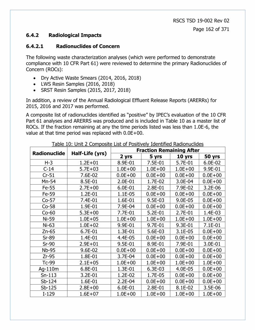
RSCS TSD 19-002 Rev 02
Page 162 of 371
6.4.2 Radiological Impacts
6.4.2.1 Radionuclides of Concern
The following waste characterization analyses (which were performed to demonstrate compliance with 10 CFR Part 61) were reviewed to determine the primary Radionuclides of Concern (ROCs):
• Dry Active Waste Smears (2014, 2016, 2018) • LWS Resin Samples (2016, 2018)
• SRST Resin Samples (2015, 2017, 2018)
In addition, a review of the Annual Radiological Effluent Release Reports (ARERRs) for 2015, 2016 and 2017 was performed.
A composite list of radionuclides identified as “positive” by IPEC’s evaluation of the 10 CFR Part 61 analyses and ARERRS was produced and is included in Table 10 as a master list of ROCs. If the fraction remaining at any the time periods listed was less than 1.0E-6, the value at that time period was replaced with 0.0E+00.
Table 10: Unit 2 Composite List of Positively Identified Radionuclides
Radionuclide Half-Life (yrs) Fraction Remaining After
2 yrs 5 yrs 10 yrs 50 yrs
H-3 1.2E+01 8.9E-01 7.5E-01 5.7E-01 6.0E-02
C-14 5.7E+03 1.0E+00 1.0E+00 1.0E+00 9.9E-01
Cr-51 7.6E-02 0.0E+00 0.0E+00 0.0E+00 0.0E+00
Mn-54 8.5E-01 2.0E-01 1.7E-02 3.0E-04 0.0E+00
Fe-55 2.7E+00 6.0E-01 2.8E-01 7.9E-02 3.2E-06
Fe-59 1.2E-01 1.1E-05 0.0E+00 0.0E+00 0.0E+00
Co-57 7.4E-01 1.6E-01 9.5E-03 9.0E-05 0.0E+00
Co-58 1.9E-01 7.9E-04 0.0E+00 0.0E+00 0.0E+00
Co-60 5.3E+00 7.7E-01 5.2E-01 2.7E-01 1.4E-03
Ni-59 1.0E+05 1.0E+00 1.0E+00 1.0E+00 1.0E+00
Ni-63 1.0E+02 9.9E-01 9.7E-01 9.3E-01 7.1E-01
Zn-65 6.7E-01 1.3E-01 5.6E-03 3.1E-05 0.0E+00
Sr-89 1.4E-01 4.4E-05 0.0E+00 0.0E+00 0.0E+00
Sr-90 2.9E+01 9.5E-01 8.9E-01 7.9E-01 3.0E-01
Nb-95 9.6E-02 0.0E+00 0.0E+00 0.0E+00 0.0E+00
Zr-95 1.8E-01 3.7E-04 0.0E+00 0.0E+00 0.0E+00
Tc-99 2.1E+05 1.0E+00 1.0E+00 1.0E+00 1.0E+00
Ag-110m 6.8E-01 1.3E-01 6.3E-03 4.0E-05 0.0E+00
Sn-113 3.2E-01 1.2E-02 1.7E-05 0.0E+00 0.0E+00
Sb-124 1.6E-01 2.2E-04 0.0E+00 0.0E+00 0.0E+00
Sb-125 2.8E+00 6.0E-01 2.8E-01 8.1E-02 3.5E-06
I-129 1.6E+07 1.0E+00 1.0E+00 1.0E+00 1.0E+00

RSCS TSD 19-002 Rev 02
Page 163 of 371
Radionuclide Half-Life (yrs) Fraction Remaining After
2 yrs 5 yrs 10 yrs 50 yrs
Cs-134 2.1E+00 5.1E-01 1.9E-01 3.5E-02 0.0E+00
Cs-137 3.0E+01 9.6E-01 8.9E-01 7.9E-01 3.2E-01
Ce-144 7.8E-01 1.7E-01 1.2E-02 1.4E-04 0.0E+00 Pu-238 8.8E+01 9.8E-01 9.6E-01 9.2E-01 6.7E-01 Pu-239 2.4E+04 1.0E+00 1.0E+00 1.0E+00 1.0E+00 Pu-240 6.6E+03 1.0E+00 1.0E+00 1.0E+00 9.9E-01 Pu-241 1.4E+01 9.1E-01 7.9E-01 6.2E-01 8.9E-02 Am-241 4.3E+02 1.0E+00 9.9E-01 9.8E-01 9.2E-01
Cm-242 4.5E-01 4.5E-02 4.2E-04 0.0E+00 0.0E+00
Cm-243 2.9E+01 9.5E-01 8.9E-01 7.9E-01 3.0E-01
Cm-244 1.8E+01 9.3E-01 8.3E-01 6.8E-01 1.5E-01
This composite list was subsequently modified (via process knowledge and a realistic analysis of each ROC’s respective half-life) and the ROCs were categorized into four distinct groups. These groups are the gamma emitters (Gammas), the Hard to Detect (HTD) and low energy beta emitters (HTD&Betas), tritium, and Transuranics (TRUs). Additionally, several ROCs were added because they are expected to be present in activated concrete (Eu-152, 154, and 155). The results are listed in Table 11.
Table 11: Unit 2 Categorized Radionuclides of Concern
Radionuclide Category Half-Life (yrs)
Chromium-51 Gammas 7.6E-02
Manganese-54 Gammas 8.5E-01
Cobalt-57 Gammas 7.4E-01
Cobalt-58 Gammas 1.9E-01
Nickel-59 Gammas 1.0E+05
Iron-59 Gammas 1.2E-01
Cobalt-60 Gammas 5.3E+00
Zinc-65 Gammas 6.7E-01
Niobium-95 Gammas 9.6E-02
Zirconium-95 Gammas 1.8E-01
Silver-110m Gammas 6.8E-01
Tin-113 Gammas 3.2E-01
Antimony-124 Gammas 1.6E-01
Antimony-125 Gammas 2.8E+00
Cesium-134 Gammas 2.1E+00
Cesium-137 Gammas 3.0E+01
Cerium-144 Gammas 7.8E-01
Europium-152b Gammas 1.3E+01

RSCS TSD 19-002 Rev 02
Page 164 of 371
Radionuclide Category Half-Life (yrs)
Europium-154b Gammas 8.6E+00
Europium-155b Gammas 4.8E+00
Carbon-14 HTD&Betas 5.7E+03
Iron-55 HTD&Betas 2.7E+00
Nickel-63 HTD&Betas 1.0E+02
Strontium-89 HTD&Betas 1.4E-01
Strontium-90 HTD&Betas 2.9E+01
Technetium-99 HTD&Betas 2.1E+05
Iodine-129a HTD&Betas 1.6E+07
Hydrogen-3 Tritium 1.2E+01
Plutonium-238 TRUs 8.8E+01
Plutonium-239 TRUs 2.4E+04
Plutonium-240 TRUs 6.6E+03
Americium-241 TRUs 4.3E+02
Plutonium-241 TRUs 1.4E+01
Curium-242 TRUs 4.5E-01
Curium-243 TRUs 2.9E+01
Curium-244 TRUs 1.8E+01 a = I-129 was not identified in site samples but is a required 10CFR20 App. G waste stream analyte
b = EU-152,154 & 155 were not identified in site samples but are typically identified in activated concrete
In summary, when analyzing samples for the presence of radioactivity, the ROCs listed in Table 11, should be requested analytes, based on the origin of the samples. Given that Units 2 and 3 are still operating, there may be a lengthy period between the time of completion of this HSA and initiation of decommissioning activities. With regard to the ultimate list of ROCs for the facility, radionuclide half-life should be considered to eliminate those radionuclides that would have decayed to negligible quantities at the time of decommissioning.
The potential presence of any of these ROCs will be denoted by their respective assigned category for the remainder of the HSA.
Radionuclides of Concern Supporting Documents
2015 Annual Radioactive Eff. Release Rpt.pdf 2016 Annual Radioactive Eff. Release Rpt.pdf 2017 Annual Radioactive Eff. Release Rpt.pdf Unit 2 DAW - 2014.pdf

RSCS TSD 19-002 Rev 02
Page 165 of 371
Unit 2 DAW - 2016.pdf Unit 2 DAW - 2018.pdf Unit 2 LWS Resin 2016.pdf Unit 2 LWS Resin 2018 data from 2014-2018.pdf Unit 2 LWS Resin 2018.pdf Unit 2 SRST Resin 2015.pdf Unit 2 SRST Resin 2017.pdf Unit 2 SRST Resin 2018.pdf

RSCS TSD 19-002 Rev 02
Page 166 of 371
6.4.2.2 Building or Structure
6.4.2.2.1 U2 Boric Acid Evaporator Building
Description and Historical Use
The Boric Acid Evaporator Building (Figure 3A, Cell B6) is a seismic Class I reinforced concrete structure supported by the roof slab of the Unit 2 waste hold-up tank pit. The exterior walls are of concrete and concrete block construction. The roof over the concrete block portion is light weight roofing over metal decking and a concrete slab is provided above the concrete wall portion.
The building contains the boric acid evaporator, gas stripper, and associated equipment (i.e. pumps, tanks, filters/demineralizers, etc.). There are also three monitor tanks mounted outside the structure.
Known and Potential Contaminants
The ROCs are those categorized as Gammas and HTD&Betas. The ROCs may be revised based upon more definitive data collected during site characterization activities.
Potentially Contaminated Media
• Steel • Concrete • Building Materials
• SSCs
Preliminary Classification
The Boric Acid Evaporator Building and all SSCs within it are preliminarily classified as a MARSSIM Class 1 structure due to the fact that the building has been an RCA throughout the station operating years, has a high potential for containing residual radioactive material, and the presumption that if residual radioactivity is present, its concentration could exceed the acceptance criteria.
Recommended Future Investigation Activities
• Direct measurements and contamination surveys of the building interior • Direct measurements and contamination surveys of the building exterior walls and
roof • Radiological analysis of concrete samples to assess volumetric contamination • Radiological analysis of sediment samples of building sumps • Radiological analysis of roofing material samples to determine volumetric
contamination

RSCS TSD 19-002 Rev 02
Page 167 of 371
6.4.2.2.2 U2 Containment Building
Description and Historical Use
The Unit 2 Reactor Containment Building (Figure 3A, Cell B6) is a steel-lined reinforced concrete cylinder with a hemispherical dome and a flat base. The containment is designed to withstand the internal pressure accompanying a loss-of-coolant accident, is virtually leak tight, and provides adequate radiation shielding for both normal operation and accident conditions.
The Containment Building houses the reactor pressure vessel, steam generators, reactor coolant pumps, pressurizer and all the SSCs associated with these major components.
Table 12: Unit 2 Containment Building Survey Summary (mR/h)
Location Area or Component Gen Area Max
RB Reactor Sump 40 *1,600/240
RB Fuel Transfer Canal 24 - 720 *1200/720
RB Cavity Core Exit Thermocouple Nozzle Assemblies (CETNA)
200 *850/350
RB Cavity Cavity floor and CETNA 8 - 44 *780/350
RB Cavity Cavity floor 10 - 260 400
RB Top of Pressurizer 3 - 80 *160/80
RB 46' 21 Reactor Coolant Pump (RCP) 1 - 20 *120/50
RB 46' 22 RCP 4 - 30 *200/90
RB 46' 23 RCP 1.5 - 30 *125/80
RB 46' 24 RCP lower platform 12 - 150 *380/150
RB 46' 21/22 Steam Generator (SG) Platform 1.2 - 15 15
RB 46' 23/24 SG Platform 1 - 20 *25/20
RB 46' Inside Containment Wall (ICW) 0.3 - 60 60
RB 46' Outside Containment Wall (OCW) 0.3 - 15 15
RB 46' Recirc Pump Room 1.2 - 12 30
RB 68' OCW General Area 0.2 - 2 10
RB 68' RHR Room 5 *250/60
RB 80' Incore Detector Boxes 3 - 25 310
RB 95' General Area 0.3 - 15 *30/15
RB 95' Bedsprings with steel still installed 5 - 100 *250/100
Note: *#/# is contact/30 cm
Known and Potential Contaminants
The ROCs are those categorized as Gammas, HTD&Betas, TRUs, and Tritium. The ROCs may be revised based upon more definitive data collected during site characterization activities.

RSCS TSD 19-002 Rev 02
Page 168 of 371
Potentially Contaminated Media
• Steel • Concrete • Building Materials
• SSCs
Preliminary Classification
The Containment Building and all SSCs within it are preliminarily classified as a MARSSIM Class 1 structure due to the fact that the building has been an RCA throughout the operating years, has a high potential for containing residual radioactive material, and the presumption that if residual radioactivity is present, its concentration could exceed the acceptance criteria.
Recommended Future Investigation Activities
• Direct measurements and contamination surveys of the building interior
• Direct measurements and contamination surveys of the building exterior walls and dome
• Radiological analysis of concrete samples to assess volumetric contamination
• Radiological analysis of sediment samples of building sumps
Supporting Documents
U2 Reactor Building surveys.pdf Unit 2 Steam Generator Tube Failure Lessons Learned Report Oct 2000.pdf
RSCS TSD 19-002 Rev 02
Page 169 of 371
6.4.2.2.3 U2 Control Building
Description and Historical Use
The IP2 control building is adjacent to the Unit 2 Turbine Generator Building on the west and the Superheater and Administration Building on the south (Figure 3A, Cell B5). The IP2 Control Building contains both the Unit 1 and Unit 2 control rooms and is a multi-story Class I steel framed structure with the north and east exterior wall consisting of insulated metal-sandwich panels. Floor slabs are composite type construction, concrete over steel beam. The Control Building houses the central control room; cable spreading room and other safety-related equipment and components.
Radioactive material was not used or stored in this building, but because of its proximity to the power block, there is the potential that trace levels of contamination may have accumulated in this building, primarily from airborne deposition on the roof and from the routine movement of personnel and equipment between buildings.
Known and Potential Contaminants
The ROCs are those categorized as Gammas and HTD&Betas. The ROCs may be revised based upon more definitive data collected during site characterization activities.
Potentially Contaminated Media
• Steel • Concrete • Building Materials
• SSCs
Preliminary Classification
The Control Building is preliminarily classified as a MARSSIM Class 3 structure based on the discussion above, and the presumption that if residual radioactivity is present, its concentration will not exceed a small fraction of the acceptance criteria.

RSCS TSD 19-002 Rev 02
Page 170 of 371
6.4.2.2.4 U2 Emergency Diesel Generator Building
Description and Historical Use
The Emergency Diesel Generator Building (Figure 3A, Cell B5) is constructed of a prefabricated rigid-frame with a solid corrugated metal roof and insulated, protected metal siding. The building houses the three emergency diesel generators, along with the associated switchgear and auxiliaries.
Radioactive material was not used or stored in this building, but because of its proximity to the power block, there is the potential that trace levels of contamination may have accumulated in this building, primarily from airborne deposition on the roof and from the routine movement of personnel and equipment between buildings.
Known and Potential Contaminants
The ROCs are those categorized as Gammas and HTD&Betas. The ROCs may be revised based upon more definitive data collected during site characterization activities.
Potentially Contaminated Media
• Steel • Concrete • Building Materials • Roofing Materials
• SSCs
Preliminary Classification
The Emergency Diesel Generator Building is preliminarily classified as a MARSSIM Class 3 structure based on the discussion above, and the presumption that if residual radioactivity is present, its concentration will not exceed a small fraction of the acceptance criteria.
Recommended Future Investigation Activities
• Direct measurements and contamination surveys of the building interior
• Direct measurements and contamination surveys of the building exterior and roof

RSCS TSD 19-002 Rev 02
Page 171 of 371
6.4.2.2.5 U2 Fuel Storage Building
Description and Historical Use
The Fuel Storage Building (Figure 3A, Cell B6) for Indian Point Unit 2 contains the spent fuel pit constructed of reinforced concrete and founded on rock. The steel superstructure above the pit encloses the pit and supports the fuel cask handling crane. This superstructure was designed as a Class III structure.
On May 7, 1992, a technician performing a walkdown of the yard outside of the Unit 2 Fuel Storage Building (FSB) noticed white powdery streaks on the exterior of the east wall of the building. Analysis of the material showed that it was boron and it contained radioactive materials, mostly Antimony (Sb-124 and Sb-125) and some Cesium (Cs-137). It was determined that in 1990, diving personnel performing cutting operations on the fuel racks perforated the Spent Fuel Pool liner.
Soil outside the building around the area where water in which the boron had been dissolved had flowed into the ground was dug up and placed into 55 gallon drums (approximately 100 drums). The maximum activity of the soil was approximately 10 pCi/g, mostly Antimony. The depth of soil removed to achieve the environmental lower limit of detection (LLD) was about 8 feet.
In September 2005, A hairline crack several feet in length was found at approximately the 60-foot level of the Unit 2 spent fuel pool south wall on the loading bay side. The crack was found during excavation associated with the dry cask storage project. In October 2005, a groundwater sample from monitoring well MW-111, located in the IP-2 Transformer Yard, indicated high levels of tritium. These events resulted in a two-year comprehensive hydrogeologic site investigation of the Indian Point Energy Center conducted by GZA GeoEnvironmental, Inc. (GZA) [8].
Known and Potential Contaminants
The ROCs are those categorized as Gammas, HTD&Betas, TRUs, and Tritium. The ROCs may be revised based upon more definitive data collected during site characterization activities.
Potentially Contaminated Media
• Steel
• Concrete • Building Materials • Roofing Materials
• SSCs
Preliminary Classification
The Fuel Storage Building and all SSCs within it are preliminarily classified as a MARSSIM Class 1 structure due to the fact that the building has been an RCA throughout the operating years, has a high potential for containing residual radioactive material, and the

RSCS TSD 19-002 Rev 02
Page 172 of 371
presumption that if residual radioactivity is present, its concentration could exceed the acceptance criteria.
Recommended Future Investigation Activities
• Direct measurements and contamination surveys of the building interior • Direct measurements and contamination surveys of the building exterior and roof • Radiological analysis of roofing material samples to determine volumetric
contamination • Radiological analysis of concrete samples to assess volumetric contamination
• Radiological analysis of sediment samples of building sumps
Supporting Documents
Adolph to Sandler memo 1992.pdf CR-IP2-2005-03557, Hairline Crack 60' level of Unit 2 SFP South Wall.pdf CR-IP2-2007-00921, Water Dripping from the Pipe Cap of PW-612 or PW-613, Primary Water in the IP-2 FSB.pdf IP2 Safety Eval No. 92-163-TR.pdf IP2 Safety Eval No. 92-165-DE.pdf Lucius Pitkin Report - Eval of IP2 SFP walls 1993.pdf May132008InsepctionReportML081340425 (1).pdf Photos of SFP Investigation.pdf U2 SFP HX leak in FSB Truck Bay 6-15-16.pdf US NRC Inspection Report No. 50-247_92-16.pdf

RSCS TSD 19-002 Rev 02
Page 173 of 371
6.4.2.2.6 U2 Maintenance Outage Building
Description and Historical Use
The Maintenance Outage Building (MOB) (Figure 3A, Cell B6) is a two-story structure used by maintenance and outage personnel as well as the security force. The building is located east of the Unit 2 Containment Building, north of the U2 Primary Auxiliary Building and adjacent to the U2 Fuel Storage Building. The building contains an elevated passageway that provides access to the U2 PAB. The south end of the building near the bridge at the connection of the MOB to the PAB contains safety-related conduit.
In 1986, the U2 Waste Holding Tank backed up into the MOB drain on the 80’ elevation resulting in flooding of the entire floor. Clean up resulted in removal of most of the contamination. However, several areas needed to be scabbled to achieve less than 100 cpm activity.
Known and Potential Contaminants
The ROCs are those categorized as Gammas, HTD&Betas, and Tritium. The ROCs may be revised based upon more definitive data collected during site characterization activities.
Potentially Contaminated Media
• Steel
• Concrete • Building Materials
• Roofing Materials
Preliminary Classification
The Maintenance Outage Building is preliminarily classified as a MARSSIM Class 1 structure due to the event discussed above, has a high potential for containing residual radioactive material, and the presumption that if residual radioactivity is present, its concentration could exceed the acceptance criteria.
Recommended Future Investigation Activities
• Direct measurements and contamination surveys of the building interior • Direct measurements and contamination surveys of the building exterior and roof • Radiological analysis of roofing material samples to determine volumetric
contamination
• Radiological analysis of sediment samples of building sumps
Supporting Documents
MOB 80' 50.75(g) Notebook Entry.pdf
RSCS TSD 19-002 Rev 02
Page 174 of 371
6.4.2.2.7 U2 Original Steam Generator Storage Facility
Description and Historical Use
The Unit 2 Original Steam Generator Storage Facility (OSGSF) (Figure 3C, Cell A5) is a reinforced concrete structure measuring approximately 150’ by 54’ constructed to house the four original steam generators. The location is within the Owner Controlled Area but outside of the Protected Area. The structure is constructed of cast-in-place concrete with the exception of the south wall, which consists of pre-cast stackable concrete blocks. The roof is covered with a single-ply membrane roofing system.
On February 15, 2000, operators determined that a steam generator tube rupture occurred and manually tripped the reactor. As a result of this event, all four (4) original steam generators were replaced and stored in the OSGSF by the end of 2000.
Known and Potential Contaminants
The ROCs are those categorized as Gammas and HTD&Betas. The ROCs may be revised based upon more definitive data collected during site characterization activities.
Potentially Contaminated Media
• Steel • Concrete • Building Materials • Roofing Materials
• SSCs
Preliminary Classification
The Original Steam Generator Storage Facility is preliminarily classified as a MARSSIM Class 2 structure based on the discussion above, and the presumption that if residual radioactivity is present, its concentration is not likely to exceed the acceptance criteria.
Recommended Future Investigation Activities
• Direct measurements and contamination surveys of the building interior
• Direct measurements and contamination surveys of the building exterior and roof
Supporting Documents
Rad Surveys of U2 Original SG Storage Facility.pdf

RSCS TSD 19-002 Rev 02
Page 175 of 371
6.4.2.2.8 U2 Primary Auxiliary Building
Description and Historical Use
The Unit 2 Primary Auxiliary Building (Figure 3A, Cell B5) is a concrete structure and is located adjacent to the Containment Building. This structure contains all support systems for reactor operations that are not located in the Containment Building. The building houses most of the auxiliary and safety systems associated with the reactor, such as radioactive waste systems, chemical and volume control systems, and emergency cooling water systems.
Table 13: Unit 2 Primary Auxiliary Building Survey Summary (mR/h)
Location Area or Component Gen Area Max
PAB 15’ 21 RHR Pump Cell 3 – 80 80
PAB 15’ RHR Piping and Valves 5 - 35 35
PAB 15’ 22 RHR Pump Cell 5 - 10 *12/7
PAB 51' Pipe Pen Catwalk 0.1 - 5 15
PAB 51' Pipe Pen - Section 1 <0.1 - 1 1
PAB 51' Pipe Pen - Section 2 1 - 15 *90/30
PAB 51' Pipe Pen - Section 3 <1 - 3 *10/3
PAB 51' Pipe Pen - Section 4 2 - 5 *10/5
PAB 51' Pipe Pen - Section 5 4 - 30 *100/30
PAB 51' Pipe Pen - Section 6 0.5 - 12 *35/25
PAB 59' Ion Exchange Valve Gallery 4 - 1,200 *38,000/2,600
PAB 59' Safety Injection Pumps 0.2 – 2 2
PAB 68' Component Cooling Pumps <0.2 - 0.8 0.8
PAB 80' 22 Charging Pump 0.5 - 1.6 2
PAB 80' 23 Charging Pump 1 -3 5
PAB 98' Volume Control Tank & Valve Corridor
0.5 - 80 *150/80
PAB 98' Non-Regenerative Heat Exchanger 2 - 45 50
Note: *#/# is contact/30 cm
Known and Potential Contaminants
The ROCs are those categorized as Gammas, HTD&Betas, and Tritium. The ROCs may be revised based upon more definitive data collected during site characterization activities.
Potentially Contaminated Media
• Steel • Concrete • Building Materials
• Roofing Materials
• SSCs

RSCS TSD 19-002 Rev 02
Page 176 of 371
Preliminary Classification
The Primary Auxiliary Building and all SSCs within it are preliminarily classified as a MARSSIM Class 1 structure due to the fact that the building has been an RCA throughout the operating years, has a high potential for containing residual radioactive material, and the presumption that if residual radioactivity is present, its concentration could exceed the acceptance criteria.
Recommended Future Investigation Activities
• Direct measurements and contamination surveys of the building interior • Direct measurements and contamination surveys of the building exterior and roof • Radiological analysis of roofing material samples to determine volumetric
contamination • Radiological analysis of concrete samples to assess volumetric contamination
• Radiological analysis of sediment samples of building sumps
Supporting Documents
U2 CCW leak 12-20-17.pdf U2 PAB surveys.pdf U2 RHR Valve Gallery Leak 4-1-18.pdf

RSCS TSD 19-002 Rev 02
Page 177 of 371
6.4.2.2.9 U2 Turbine Generator Building
Description and Historical Use
The Unit 2 Turbine Generator Building (Figure 3A, Cells B5 and B6) houses the Unit 2 Turbine Generator and associated auxiliaries, the Condenser, Condensate and Feedwater Systems, switchgear, the Turbine Building crane, and other auxiliary equipment. The Turbine Building is a rigid steel and concrete structure.
Due to the steam generator tube rupture in February of 2000, contamination was transported to various systems within the Turbine Building.
Known and Potential Contaminants
The ROCs are those categorized as Gammas and HTD&Betas. The ROCs may be revised based upon more definitive data collected during site characterization activities.
Potentially Contaminated Media
• Steel • Concrete • Building Materials • Roofing Materials
• SSCs
Preliminary Classification
The Turbine Generator Building and all SSCs within are preliminarily classified as a MARSSIM Class 3 structure based on the discussion above, and the presumption that if residual radioactivity is present, its concentration will not exceed a small fraction of the acceptance criteria.
Recommended Future Investigation Activities
• Direct measurements and contamination surveys of the building interior
• Direct measurements and contamination surveys of the building exterior and roof
• Radiological analysis of sediment samples of building sumps

RSCS TSD 19-002 Rev 02
Page 178 of 371
6.4.2.3 Exterior Area
6.4.2.3.1 U2 Fuel Storage Building Alleyway
Description and Historical Use
On May 7, 1992, a technician performing a walkdown of the yard outside of the Fuel Storage Building (FSB) (Figure 3A, Cell B6) noticed white powdery streaks on the exterior of the east wall of the building. Analysis of the material showed that it was boron and it contained radioactive materials, mostly Antimony (Sb-124 and Sb-125) and some Cesium (Cs-137).
Soil outside the building around the area where the water had flowed into the ground was dug up and placed into 55-gallon drums (approximately 100 drums). The maximum activity of the soil was approximately 13 pCi/g, mostly Antimony. The depth of soil removed to achieve the environmental lower limit of detection (LLD) was about 8 feet [NRC Inspection Report No: 50-247/92-16].
On April 14, 2006 during multiple system tests of the Supplemental Spent Fuel Pool Cooling System, about 200 gallons of secondary side water containing approximately 20,000 pCi/L of tritium overflowed from the cooling tower. The water overflowed out of the secondary side tower basin on to the asphalt and concrete area in the FSB Alleyway, and some runoff also went into the soil and storm drain located across the alleyway. The overflow was caused by stopping the secondary side pumps, which allowed the dead leg of the return line water to empty into the tower basin without being pumped back out [CR-IP2-2006-01896].
Known and Potential Contaminants
The ROCs are those categorized as Gammas, HTD&Betas, and Tritium. The ROCs may be revised based upon more definitive data collected during site characterization activities.
Potentially Contaminated Media
• Asphalt • Soil • Concrete
• Gravel
Preliminary Classification
The Fuel Storage Building Alleyway is preliminarily classified as a MARSSIM Class 1 area based on the discussion above, and the presumption that if residual radioactivity is present, its concentration could exceed the acceptance criteria.
Recommended Future Investigation Activities
• Gamma walkover survey to identify any areas with elevated activity
• Radiological analysis of media samples taken in a systematic fashion

RSCS TSD 19-002 Rev 02
Page 179 of 371
Supporting Documents
CR-IP2-2006-01896 SFPBUHX overflow to yard and storm drains.pdf CR-IP2-2014-02441, Small Leak of Cont. Water from BUSFPC System Filter Housing.pdf TID-03-008, PAB Alleyway Outside Drumming Room.pdf

RSCS TSD 19-002 Rev 02
Page 180 of 371
6.4.2.3.2 U2 Retired RAM Pen
Description and Historical Use
The Retired RAM Pen (Figure 3C, Cell C6), also referred to as the City Water Tank RMSA, is a grassy area surrounded by chain link fence near, but physically separated from, the City Water Tank. The area was used for the storage of contained radioactive material. The Retired RAM Pen is located within the Owner Controlled Area but outside of the Protected Area. During site tours conducted in December 2018, the pen was observed to be empty.
A radiological survey, located in the 50.75g file, contained the results of a soil sample taken from the area in 1994. The analysis of the sample identified Co-60 (2.6 pCi/g) and Cs-137 (0.7 pCi/g).
During interviews it was stated that the RAM Pen is no longer used, however, radiological postings are still in place on the fence surrounding the area.
Known and Potential Contaminants
The ROCs are those categorized as Gammas and HTD&Betas. The ROCs may be revised based upon more definitive data collected during site characterization activities.
Potentially Contaminated Media
• Soil
Preliminary Classification
The Retired RAM Pen is preliminarily classified as a MARSSIM Class 2 area, based on the presumption that if residual radioactivity is present, its concentration is not likely to exceed the acceptance criteria.
Recommended Future Investigation Activities
• Gamma walkover survey to identify any areas with elevated activity
• Radiological analysis of soil samples taken in a systematic fashion
Supporting Documents
City Water Tank RMSA Soil Notebook Entry.pdf TID-04-006, Retired RAM Pen Soil Samples.pdf

RSCS TSD 19-002 Rev 02
Page 181 of 371
6.4.2.3.3 U2 Transformer Yard
Description and Historical Use
The Unit 2 Transformer Yard (Figure 3A, Cell B5) contains the 21 and 22 Main Transformers, Station Auxiliary Transformer and Unit Auxiliary Transformer.
In 1992, the Electrical Tunnel deluge line to the Transformer Yard was contaminated by an Evaporator overflow. Surface samples and scrapes near the outlet identified both Cs-137 and Co-60, with values ranging from approximately 1 pCi/g to 100 pCi/g. In 1994, the PAB wall was disassembled to remove motors from the RHR pumps. At that time, several composite samples were obtained outside the RHR door and at the edge of the storm drain, near the hydrant. Both Cs-137 and Co-60 were identified, with values ranging from approximately 0.1 pCi/g to 3 pCi/g.
Known and Potential Contaminants
The ROCs are those categorized as Gammas and HTD&Betas. The ROCs may be revised based upon more definitive data collected during site characterization activities.
Potentially Contaminated Media
• Asphalt • Soil • Concrete
• Gravel
Preliminary Classification
The areas identified above are preliminarily classified as a MARSSIM Class 1 based on the discussion above, and the presumption that if residual radioactivity is present, its concentration could exceed the acceptance criteria. For planning purposes, the Class 1 portion of the yard should extend out 5 meters from the entire length of the PAB west wall and 5 meters from the Control Building north wall up to the 22 Main Transformer. The balance of the Transformer Yard is preliminarily classified as a MARSSIM Class 2 area, based on the presumption that if residual radioactivity is present, its concentration is not likely to exceed the acceptance criteria.
Recommended Future Investigation Activities
• Gamma walkover survey to identify any areas with elevated activity
• Radiological analysis of media samples taken in a systematic fashion
Supporting Documents
Elec. Tunnel Deluge to XFRMR Yard Notebook Entry.pdf U2 Transformer Yard at RHR Wall 50.75(g) Notebook Entry.pdf U2 Transformer Yard ET Deluge Line 50.75(g) Notebook Entry.pdf U2 Transformer Yard Soil Samples.pdf XFRMR Yard Soil Notebook Entry.pdf

RSCS TSD 19-002 Rev 02
Page 182 of 371
6.4.2.4 Storage Tanks
6.4.2.4.1 U2 Condensate Storage Tank CST
Description and Historical Use
The Unit 2 Condensate Storage Tank (CST) (Figure 3A, Cell B6) is a 600,000-gallon storage tank which is constructed of carbon steel with a phenolic liner and has a floating diaphragm on the surface of the water to exclude air.
Known and Potential Contaminants
The ROCs are those categorized as Gammas and HTD&Betas. The ROCs may be revised based upon more definitive data collected during site characterization activities.
Potentially Contaminated Media
• Steel
• SSCs
Preliminary Classification
The Condensate Storage Tank and associated SSCs are preliminarily classified as a MARSSIM Class 3 SSC based on the radioactive content of the water it was designed to store, and the presumption that if residual radioactivity is present, its concentration will not exceed a small fraction of the acceptance criteria.
Recommended Future Investigation Activities
• Direct measurements and contamination surveys of the tank interior
• Direct measurements and contamination surveys of the tank exterior

RSCS TSD 19-002 Rev 02
Page 183 of 371
6.4.2.4.2 U2 Monitor Tanks
Description and Historical Use
The Unit 2 Monitor Tanks, (Figure 3A, Cell C5) located adjacent to and south of the Boric Acid Evaporator Building, were used to store water that had been processed through the evaporators. The water would be circulated and monitored for radioactivity and other chemical parameters prior to discharge. As with the evaporator system, the monitor tanks were retired in the early 1980s.
Known and Potential Contaminants
The ROCs are those categorized as Gammas and HTD&Betas. The ROCs may be revised based upon more definitive data collected during site characterization activities.
Potentially Contaminated Media
• Steel
• SSCs
Preliminary Classification
The Monitor Tanks and associated SSCs are preliminarily classified as a MARSSIM Class 2 SSC based on the radioactive content of the water they were designed to store, and the presumption that if residual radioactivity is present, its concentration is not likely to exceed the acceptance criteria.
Recommended Future Investigation Activities
• Direct measurements and contamination surveys of the interior of the tanks
• Direct measurements and contamination surveys of the exterior of the tanks

RSCS TSD 19-002 Rev 02
Page 184 of 371
6.4.2.4.3 U2 Primary Water Storage Tank PWST
Description and Historical Use
The Unit 2 Primary Water Storage Tank (PWST) (Figure 3A, Cell C5) is a 165,000-gallon tank constructed of Type 304 stainless steel with a floating diaphragm to exclude air. The main purpose of the PWST is to store water of a suitable quality for make-up to the primary coolant system.
Known and Potential Contaminants
The ROCs are those categorized as Gammas, HTD&Betas, and Tritium. The ROCs may be revised based upon more definitive data collected during site characterization activities.
Potentially Contaminated Media
• Steel
• SSCs
Preliminary Classification
The Primary Water Storage Tank is preliminarily classified as a MARSSIM Class 3 SSC based on the discussion above, and the presumption that if residual radioactivity is present, its concentration will not exceed a small fraction of the acceptance criteria.
Recommended Future Investigation Activities
• Direct measurements and contamination surveys of the tank interior
• Direct measurements and contamination surveys of the tank exterior

RSCS TSD 19-002 Rev 02
Page 185 of 371
6.4.2.4.4 U2 Refueling Water Storage Tank RWST
Description and Historical Use
The Unit 2 Refueling Water Storage Tank (RWST) (Figure 3A, Cell C5) has a nominal capacity of 395,000 gallons of borated water. The purpose of the tank is to supply borated water to the refueling canal for refueling operations and to the safety injection pumps, the residual heat removal pumps, and the containment spray pumps for accidents requiring safety injection. Following refueling operations, water from the refueling canal is pumped back into the RWST.
Known and Potential Contaminants
The ROCs are those categorized as Gammas, HTD&Betas, and Tritium. The ROCs may be revised based upon more definitive data collected during site characterization activities.
Potentially Contaminated Media
• Steel
• SSCs
Preliminary Classification
The Refueling Water Storage Tank and associated SSCs are preliminarily classified as a MARSSIM Class 1 SSC based on the radioactive content of the water it was designed to store, and the presumption that if residual radioactivity is present, its concentration could exceed the acceptance criteria.
Recommended Future Investigation Activities
• Direct measurements and contamination surveys of the tank interior
• Direct measurements and contamination surveys of the tank exterior

RSCS TSD 19-002 Rev 02
Page 186 of 371
Unit 3 Impacts
6.5.1 Non-Radiological Impacts
6.5.1.1 Building or Structure
6.5.1.1.1 U3 Auxiliary Feedwater Pump Building
Description and Historical Use
The Unit 3 Auxiliary Feedwater Pump Building is located adjacent to the northwest quadrant of the Unit 3 Containment Building (Figure 3A, Cell B4). The building houses four feedwater pumps each containing approximately 200 gallons of lubricating oil. No record of a release of hazardous material from the Unit 3 Auxiliary Feedwater Pump Building has been found.
Known and Potential Contaminants
The non-radiological contaminants are Lubricating Oil and RCRA Metals. If handled properly, these materials are not expected to pose a risk of contamination to environmental media such as soil or groundwater.
Potentially Contaminated Media
• Building Materials (Floor)
Preliminary Classification
Based on their location within the Unit 3 Auxiliary Feedwater Pump Building and the volume of lubricating oil that could be released from the Auxiliary Feedwater Pumps a preliminary classification of NR Isolated is assigned to the building.
Recommended Future Investigation Activities
Inspect the concrete floor for indications of staining, cracks or openings that could release the Potential Contaminants to the environment.

RSCS TSD 19-002 Rev 02
Page 187 of 371
6.5.1.1.2 U3 Circulation Water Pump Building
Description and Historical Use
The Unit 3 Circulation Water Pump Building is part of the Unit 3 Intake Structure, located next to the Hudson River, west of the Unit 3 Turbine Generator Building (Figure 3A, Cells A3 to A4). The building houses Circulating Water and Service Pumps containing a total of approximately 600 gallons of lubricating oil. No record of a release of hazardous material from the Unit 3 Circulation Water Pump Building has been found.
Known and Potential Contaminants
The non-radiological contaminants are Lubricating Oil and RCRA Metals.
Potentially Contaminated Media
• Building Materials (Floor)
Preliminary Classification
Based on their location within the Unit 3 Circulation Water Pump Building and the volume of lubricating oil that could be released from the Circulation Water and Service Pumps a preliminary classification of NR Isolated is assigned to the building.
Recommended Future Investigation Activities
Inspect the concrete floor for indications of staining, cracks or openings that could release the Potential Contaminants to the environment.

RSCS TSD 19-002 Rev 02
Page 188 of 371
6.5.1.1.3 U3 Emergency Diesel Generator Building
Description and Historical Use
The Unit 3 Emergency Diesel Generator Building houses three Emergency Diesel Generators, each containing approximately 150 gallons of lubricating oil. The building is located north of the Unit 3 Outage Support Building (Figure 3A, Cell B3). No record of a release of hazardous material from the Unit 3 Emergency Diesel Generator Building has been found.
Known and Potential Contaminants
The non-radiological contaminants are Diesel Fuel, Lubricating Oil, and RCRA Metals. If handled properly, these materials are not expected to pose a risk of contamination to environmental media such as soil or groundwater.
Potentially Contaminated Media
• Building Materials (Floor)
Preliminary Classification
Based on their location within the Unit 3 Emergency Diesel Generator Building and the volume of lubricating oil that could be released from the Emergency Diesel Generators a preliminary classification of NR Isolated is assigned to the building.
Recommended Future Investigation Activities
Inspect the concrete floor for indications of staining, cracks or openings that could release the Potential Contaminants to the environment.

RSCS TSD 19-002 Rev 02
Page 189 of 371
6.5.1.1.4 U3 Intake Structure
Description and Historical Use
The Unit 3 Intake Structure (Figure 3A, Cells A3 to A4) is the location of the station water intake components including the trash racks, traveling screens and pumps for the circulation water, service water and fire protection systems.
Sodium hypochlorite is stored in two fiberglass above ground storage tanks and is injected into the circulating water to limit biofouling of the condenser and into the service water to limit biofouling of heat exchangers. No record of a release of hazardous material from the Intake Structure has been found.
Known and Potential Contaminants
The non-radiological contaminants are Lubricating Oil, RCRA Metals, and Sodium Hypochlorite. If handled properly, these materials are not expected to pose a risk of contamination to environmental media such as soil or groundwater.
Potentially Contaminated Media
• Building Materials (Floor)
Preliminary Classification
Based on their location within the Unit 3 Intake Structure and the volume of lubricating oil and sodium hypochlorite that could be released from the pumps and tanks a preliminary classification of NR Isolated is assigned to the building.
Recommended Future Investigation
Inspect the concrete floor for indications of staining, cracks or openings that could release the Potential Contaminants to the environment.

RSCS TSD 19-002 Rev 02
Page 190 of 371
6.5.1.1.5 U3 Radioactive Machine Shop
Description and Historical Use
The Unit 3 Radioactive Machine Shop (RAMS) (Figure 3A, Cell C3) contains various machining tools such as lathes, saws and drill presses. Lubricating and cutting oils are used in the shop in relatively small volumes. No record of a release of hazardous material from the shop has been found.
Known and Potential Contaminants
The non-radiological contaminants are Waste Oil, Cutting Oil, Hydraulic Oil, Lubricating Oil, RCRA Metals, and Spent Solvents. If handled properly, these materials are not expected to pose a risk of contamination to environmental media such as soil or groundwater.
Potentially Contaminated Media
• Building Materials (Floor)
• Tools
Preliminary Classification
Based on their location within the Unit 3 Radioactive Machine Shop and the volume of hazardous materials that could be released a preliminary classification of NR Isolated is assigned to the Shop.
Recommended Future Investigation Activities
Inspect the concrete floor for indications of staining, cracks or openings that could release the Potential Contaminants to the environment.
RSCS TSD 19-002 Rev 02
Page 191 of 371
6.5.1.1.6 U3 Turbine Generator Building
Description and Historical Use
The Unit 3 Turbine Generator Building (Figure 3A, Cells B3 to B4) houses the Unit 3 Turbine Generator and associated auxiliaries, the Condenser, Condensate and Feedwater Systems, switchgear, the Turbine Building crane, and other auxiliary equipment. The Turbine Generator Building is a rigid steel and concrete structure.
Structural steel members in the building are assumed to be coated with lead-based paint. Various components such as pump and valve gaskets and pipe wrap may contain asbestos. Other components such as electrical switches, relays, thermostats and gauges may contain mercury.
As discussed in Subsection 4.2.2.1, in 1989 3,500 gallons of lubricating oil was released from a corroded return line beneath the Unit 3 Turbine Generator Building [23]. Oil also was released from the R4D4 Sludge Tank to the Unit 3 Turbine Generator Building floor and the Discharge Canal in 1991 (SOR-91-3-109).
In 1995 oil was detected issuing from floor drains of the Unit 3 Turbine Generator Building 5-foot elevation and seeping into the Discharge Canal (CR-IP3-1995-00524). The oil was removed from the floor drains and the drains were repaired. An investigation by Foster Wheeler, a hydrogeologic consultant, could not provide a definitive solution to the contamination event without performing additional studies [24].
As of spring of 1998 no additional oil was evident and no seepage into the discharge canal had been detected. Buried safety-related utilities are located in the area where oil had been detected and further subsurface investigation there would have risked damage to vital plant equipment. Because of this condition, the absence of further evidence of oil seepage into the canal and the apparent low risk of environmental impact, inspectors from the NYSDEC agreed that there was no benefit to be gained from additional investigation. A monitoring program in nearby groundwater monitoring wells was established [20] [24].
Known and Potential Contaminants
The non-radiological contaminants are Asbestos, Lead, Lubricating Oil, Waste Oil, and RCRA Metals.

RSCS TSD 19-002 Rev 02
Page 192 of 371
Potentially Contaminated Media
• Building Materials (Floor) • Floor Drains • Lead Paint
• Asbestos • Mercury • Soil • Groundwater
• Sumps
Preliminary Classification
Because of the known release of Lubricating Oil from the Unit 3 Turbine Generator Building and the potential that residual oil may remain beneath the building, a preliminary classification of NR Class 1 is assigned to the building.
Recommended Future Investigation Activities
Collect additional samples of soil and groundwater in the area of interest and analyze the samples for the Potential Contaminants.
Supporting Documents
Memo from NYPA re Status of T.H. 5' Remediation Project 4-20-99.pdf Memo to ENZ re IP3 TB Oil Plume Investigation 11-24-99.PDF Memo to P.Gauron, PC and C.Wells re NYPA Acquisiton .PDF SOR 91-3-109 U3 Oil Spill to Turbine Building and Discharge Canal 5-25-1991.pdf SOR 91-3-144 Follow up to SOR-91-3-144 U3 Turbine Lube Oil Separator Overflow.pdf TLG's Draft Report - Radiological and Hazardous Condition Assessment of ....pdf

RSCS TSD 19-002 Rev 02
Page 193 of 371
6.5.1.2 Chemical and Drum Storage Areas
6.5.1.2.1 U3 Hazardous Waste Storage Building
Description and Historical Use
Because Units 2 and 3 have separate permits to generate hazardous waste in accordance with provisions of the U.S. Resource Conservation and Recovery Act (RCRA), each Unit must store their hazardous waste separately. However, Universal Wastes from both Unit 2 and Unit 3 are stored in the Unit 3 Hazardous Waste Storage Building.
As a Large Quantity Generator, Unit 3 stores no more than 1,000 kilograms per month in its Hazardous Waste Storage Building, located north of the Training Fire Pump Diesel Storage Tank (Figure 5, Cell C3). No record of a release of hazardous material in this building has been found.
Known and Potential Contaminants
The non-radiological contaminants are Acids-Bases, Batteries, Lead, Mercury, Spent Solvents, and RCRA Metals. If handled properly, these materials are not expected to pose a risk of contamination to environmental media such as soil or groundwater.
Potentially Contaminated Media
• Building Materials (Floor)
Preliminary Classification
Because the wastes are contained within an enclosed structure, the Unit 3 Hazardous Waste Storage Building is assigned a preliminary classification of NR Isolated.
Recommended Future Investigation Activities
Inspect the floor of the Unit 3 Hazardous Waste Storage Building for indications of staining, cracks or openings that could release the Potential Contaminants to the environment.
RSCS TSD 19-002 Rev 02
Page 194 of 371
Chemical and Drum Storage Areas Supporting Documents
EN-EV-106__007.pdf IP3 CBS_PBS and RCRA LQG & TSD Applications.pdf IP3 Mixed Waste TSDF Permits 6-8-2000.pdf IPEC Haz. Waste Inventory.pdf
RSCS TSD 19-002 Rev 02
Page 195 of 371
6.5.1.3 Exterior Area
6.5.1.3.1 U3 Soil Pile Posted as Lead Hazard
Description and Historical Use
As discussed in Subsection 4.2.2.1, an approximately six-foot high pile of soil posted as a lead hazard was identified in 2000 in a lay-down area southwest of the Training Center and north of the U3 Original Steam Generator Storage Facility (Figure 3B, Cell B4) [20]. Unit 3 staff identified the area as one where equipment presumably coated with lead-based paint was sandblasted. The soil pile has been removed from the station.
Known and Potential Contaminants
The non-radiological contaminants are Lead and RCRA Metals.
Potentially Contaminated Media
• Soil
• Groundwater
Preliminary Classification
Although the soil pile has been removed, because it was in an open lay-down area and no documentation of its removal or remediation has been found, the Unit 3 Soil Pile Posted as Lead Hazard is assigned a preliminary classification of NR Class 3.
Recommended Future Investigation Activities
Collect surface soil samples in the area of the former soil pile and analyze the samples for the Potential Contaminants.

RSCS TSD 19-002 Rev 02
Page 196 of 371
6.5.1.3.2 U3 Transformer Yard
Description and Historical Use
The Unit 3 Transformer Yard (Figure 5, Cell B7) contains the 31 and 32 Main Transformers, Unit Auxiliary Transformer and Station Auxiliary Transformer.
As discussed in Subsection 4.2.2.1, oil staining was observed on the 31 and 32 Main Transformers, their concrete footings and surrounding soil in 2000 during a radiological and hazardous condition assessment of the Unit 3 Site ( [20].
A bushing failure in the 31 Main Transformer in 2007 resulted in a 5-gallon release of transformer oil (CR-IP3-2007-01844; NYSDEC Spill Report 700825).
An internal fault and fire in 2015 in a replacement 31 Main Transformer resulted in an oil release to soil and the Discharge Canal. (CR-IP3-2015-02916; NYSDEC Spill Report 1501459); [16] [17] [21] [22]. The deluge system that automatically engaged to extinguish the fire released a large volume of fire-suppression foam and water. As a result, water and transformer oil overflowed the berm containing the transformer, infiltrated surrounding soil, entered the local storm drain and flowed to the Discharge Canal. The contaminated trap rock within the berm was removed, an impermeable liner was applied to the berm floor and walls, clean trap rock was placed in the berm and a replacement 31 Main Transformer was installed.
Known and Potential Contaminants
The non-radiological contaminant is Dielectric Oil.
Potentially Contaminated Media
• Soil • Groundwater • Concrete
• Trap Rock
Preliminary Classification
The Unit 3 Transformer Yard is assigned a preliminary classification of NR Class 1.
Recommended Future Investigation Activities
Collect additional samples of soil and groundwater in the area of interest and analyze the samples for the Potential Contaminants.
Supporting Documents
31 Main Transformer Spill, etc Closeout.pdf CR-IP3-1997-02006, 5 gallons of hydraulic oil spilled to ground from fork lift.pdf

RSCS TSD 19-002 Rev 02
Page 197 of 371
6.5.1.4 Oil-Filled Mechanical Equipment
6.5.1.4.1 U3 Appendix R Diesel Generator
Description and Historical Use
The Unit 3 Appendix R Diesel Generator is located north of the Unit 3 Containment Building (Figure 5, Cell B7) and contains approximately 100 gallons of lubricating oil. No record of a release of hazardous material from the Unit 3 Appendix R Diesel Generator enclosure has been found.
Known and Potential Contaminants
The non-radiological contaminants are Diesel Fuel, Lubricating Oil, and RCRA Metals. If handled properly, these materials are not expected to pose a risk of contamination to environmental media such as soil or groundwater.
Potentially Contaminated Media
• Building Materials (Floor)
Preliminary Classification
Because the Unit 3 Appendix R Diesel Generator is located within an enclosure it is not likely that releases of Diesel Fuel or Lubricating Oil that may have occurred from the Generator have caused gross contamination of soil or groundwater. The Generator is assigned a preliminary classification of NR Isolated.
Recommended Future Investigation Activities
Inspect the floor of the Unit 3 Appendix R Diesel Generator enclosure for indications of staining, cracks or openings that could release the Potential Contaminants to the environment.

RSCS TSD 19-002 Rev 02
Page 198 of 371
6.5.1.4.2 U3 Building Elevators
Description and Historical Use
An elevator in the Unit 3 Administration Building contains an approximately 50-gallon reservoir of hydraulic oil. No record of a release of hazardous material from this elevator has been found.
Known and Potential Contaminants
The non-radiological contaminants are Hydraulic Oil and RCRA Metals. If handled properly, these materials are not expected to pose a risk of contamination to environmental media such as soil or groundwater.
Potentially Contaminated Media
• Building Materials (Floor)
• Concrete
Preliminary Classification
Because the Unit 3 Administration Building Elevator is contained within the building it serves, it is not likely that releases that may have occurred from the hydraulic oil reservoir have caused gross contamination of soil or groundwater. This building elevator is assigned a preliminary classification of NR Isolated.
Recommended Future Investigation Activities
Inspect the area of the hydraulic oil reservoir and the bottom of the elevator shaft for indications of staining, cracks or openings that could release the Potential Contaminants to the environment.

RSCS TSD 19-002 Rev 02
Page 199 of 371
6.5.1.4.3 U3 Circulation Water Pump Motors
Description and Historical Use
The Unit 3 Circulation Water Pumps are located in the Unit 3 Intake Structure (Figure 3A, Cells A3 to A4), downstream from the trash rack and traveling screens. Each pump motor contains approximately 100 gallons of lubricating oil. No record of a release of lubricating oil from the pump motors has been found.
Known and Potential Contaminants
The non-radiological contaminants are Lubricating Oil and RCRA Metals. If handled properly, these materials are not expected to pose a risk of contamination to environmental media such as soil or groundwater.
Potentially Contaminated Media
• Building Materials (Floor)
Preliminary Classification
Based on their location in the Intake Structure it is not likely that releases of Lubricating Oil that may have occurred from the Unit 3 Circulating Water Pump Motors have caused gross contamination of soil or groundwater. The Circulating Water Pump Motors are assigned a preliminary classification of NR Isolated.
Recommended Future Investigation Activities
Inspect the area of the Circulation Water Pump Motors for indications of staining, cracks or openings that could release the Potential Contaminants to the environment.

RSCS TSD 19-002 Rev 02
Page 200 of 371
6.5.1.4.4 U3 Condensate Pump Motors
Description and Historical Use
The Unit 3 Condensate Pumps are located in the Unit 3 Turbine Generator Building (Figure 3A, Cells B3 to B4). All drains from the Turbine Generator Building flow to Radwaste for treatment and to ensure that no oil or unmonitored radioactivity leaves the building. The pump motors contain a total of approximately 300 gallons of lubricating oil. No record of a release of lubricating oil from the pump motors has been found.
Known and Potential Contaminants
The non-radiological contaminants are Lubricating Oil and RCRA Metals. If handled properly, these materials are not expected to pose a risk of contamination to environmental media such as soil or groundwater.
Potentially Contaminated Media
• Building Materials (Floor)
Preliminary Classification
Based on their location within the Unit 3 Turbine Generator Building it is not likely that releases of Lubricating Oil that may have occurred from the Pump Motors have caused gross contamination of soil or groundwater. The Unit 3 Condensate Pump Motors are assigned a preliminary classification of NR Isolated.
Recommended Future Investigation Activities
Inspect the area of the Condensate Pump Motors for indications of staining, cracks or openings that could release the Potential Contaminants to the environment.

RSCS TSD 19-002 Rev 02
Page 201 of 371
6.5.1.4.5 U3 Diesel Fire Pump Motor
Description and Historical Use
The Unit 3 Diesel Fire Pump is located in a building next to the Unit 3 Fire Water Storage Tanks (Figure 5, Cell B7). The pump motor contains approximately 100 gallons of lubricating oil. No record of a release of lubricating oil from the pump motor has been found.
Known and Potential Contaminants
The non-radiological contaminants are Diesel Fuel, Lubricating Oil, and RCRA Metals. If handled properly, these materials are not expected to pose a risk of contamination to environmental media such as soil or groundwater.
Potentially Contaminated Media
• Building Materials (Floor)
Preliminary Classification
Based on its location within a small building it is not likely that releases of Diesel Fuel or Lubricating Oil that may have occurred from the Unit 3 Diesel Fire Pump Motor has caused gross contamination of soil or groundwater. A preliminary classification of NR Isolated is assigned to the Pump Motor.
Recommended Future Investigation Activities
Inspect the area of the Unit 3 Diesel Fire Pump Motor for indications of staining, cracks or openings that could release the Potential Contaminants to the environment.

RSCS TSD 19-002 Rev 02
Page 202 of 371
6.5.1.4.6 U3 Emergency Diesel Generators
Description and Historical Use
The Unit 3 Emergency Diesel Generators are located in the Unit 3 Emergency Diesel Generator Building (Figure 5, Cell B6). Each of the three generators contain approximately 150 gallons of lubricating oil. No record of a release of lubricating oil from the Unit 3 Emergency Diesel Generators has been found.
Known and Potential Contaminants
The non-radiological contaminants are Diesel Fuel, Lubricating Oil, and RCRA Metals. If handled properly, these materials are not expected to pose a risk of contamination to environmental media such as soil or groundwater.
Potentially Contaminated Media
• Building Materials (Floor)
Preliminary Classification
Based on their location within the Unit 3 Emergency Diesel Generator Building it is not likely that releases of Diesel Fuel or Lubricating Oil that may have occurred from the Generators has caused gross contamination of soil or groundwater. The Unit 3 Emergency Diesel Generators are assigned a preliminary classification of NR Isolated.
Recommended Future Investigation Activities
Inspect the area of the Unit 3 Emergency Diesel Generators for indications of staining, cracks or openings that could release the Potential Contaminants to the environment.

RSCS TSD 19-002 Rev 02
Page 203 of 371
6.5.1.4.7 U3 Technical Support Center Emergency Diesel Generator
Description and Historical Use
The Unit 3 Technical Support Center Emergency Diesel Generator is located at the south end of the Unit 3 Turbine Generator Building (Figure 5, Cell B3). The generator contains approximately 100 gallons of diesel fuel and lubricating oil. No record of a release of diesel fuel or lubricating oil from the Unit 3 Technical Support Center Emergency Diesel Generator has been found.
Known and Potential Contaminants
The non-radiological contaminants are Diesel Fuel, Lubricating Oil, and RCRA Metals. If handled properly, these materials are not expected to pose a risk of contamination to environmental media such as soil or groundwater.
Potentially Contaminated Media
• Building Materials (Floor)
Preliminary Classification
Based on its location within the Unit 3 Turbine Generator Building it is not likely that releases of Diesel Fuel or Lubricating Oil that may have occurred from the generator has caused gross contamination of soil or groundwater. The Unit 3 Technical Support Center Emergency Diesel Generator is assigned a preliminary classification of NR Isolated.
Recommended Future Investigation Activities
Inspect the area of the Unit 3 Technical Support Center Emergency Diesel Generator for indications of staining, cracks or openings that could release the Potential Contaminants to the environment.

RSCS TSD 19-002 Rev 02
Page 204 of 371
6.5.1.5 Storage Tanks
6.5.1.5.1 U3 31 Emergency Diesel Generator Day Tank DD1
Description and Historical Use
The Unit 3 31 Emergency Diesel Generator Day Tank is a 175-gallon steel above ground tank located in the Unit 3 Emergency Diesel Generator Building (Figure 5, Cell B6). No record of a release of diesel fuel from this tank has been found.
Known and Potential Contaminants
The non-radiological contaminant is Diesel Fuel. If handled properly, this material is not expected to pose a risk of contamination to environmental media such as soil or groundwater.
Potentially Contaminated Media
• Building Materials (Floor)
Preliminary Classification
Because the Unit 3 31 Emergency Diesel Generators Day Tank is located inside the Unit 3 Emergency Diesel Generator Building with secondary containment, a release of diesel fuel from the tank is unlikely to result in gross contamination of soil or groundwater. The area of this AST is assigned a preliminary classification of NR Isolated.
Recommended Future Investigation Activities
Inspect the area of the Unit 3 31 Emergency Diesel Generator Day Tank for indications of staining, cracks or openings that could release the Potential Contaminants to the environment.

RSCS TSD 19-002 Rev 02
Page 205 of 371
6.5.1.5.2 U3 31 Emergency Diesel Generator Storage Tank 31EDG
Description and Historical Use
The Unit 3 31 Emergency Diesel Generator Storage Tank is a 7,700-gallon steel underground tank located adjacent to the Unit 3 Emergency Diesel Generator Building (Figure 5, Cell B6). No record of a release of diesel fuel from this tank has been found.
Known and Potential Contaminants
The non-radiological contaminant is Diesel Fuel.
Potentially Contaminated Media
• Soil
• Groundwater
Preliminary Classification
Because the Unit 3 31 Emergency Diesel Generator Storage Tank is an underground tank storing a large volume of diesel fuel that could be released due to undetected leakage or overfilling during deliveries, a preliminary classification of NR Class 1 is assigned to the tank.
Recommended Future Investigation Activities
Inspect the area surrounding the fill port for the tank for indications of a release of the Potential Contaminants to the environment.
Collect soil samples from the tank grave when the tank is removed and analyze the samples for constituents of diesel fuel.

RSCS TSD 19-002 Rev 02
Page 206 of 371
6.5.1.5.3 U3 31 Main Boiler Feed Pump Oil Accumulator Tank 31LOA
Description and Historical Use
Unit 3 31 Main Boiler Feed Pump Oil Accumulator Tank 31LOA is an 80-gallon above ground storage tank containing lubricating oil and is located in the Unit 3 Turbine Generator Building (Figure 5, Cell A6). No record of a release of lubricating oil from this tank has been found.
Known and Potential Contaminants
The non-radiological contaminant is Lubricating Oil. If handled properly, this material is not expected to pose a risk of contamination to environmental media such as soil or groundwater.
Potentially Contaminated Media
• Building Materials (Floor) • Sumps • Concrete
• Floor Drains
Preliminary Classification
Because Unit 3 31 Main Boiler Feed Pump Oil Accumulator Tank 31LOA is located inside the Unit 3 Turbine Generator Building with secondary containment, a release of lubricating oil from the tank is unlikely to result in gross contamination of soil or groundwater. The area of this AST is assigned a preliminary classification of NR Isolated.
Recommended Future Investigation Activities
Inspect the area of Unit 3 31 Main Boiler Feed Pump Oil Accumulator Tank 31LOA for indications of staining, cracks or openings that could release the Potential Contaminants to the environment.

RSCS TSD 19-002 Rev 02
Page 207 of 371
6.5.1.5.4 U3 32 Emergency Diesel Generator Day Tank DD2
Description and Historical Use
The Unit 3 32 Emergency Diesel Generator Day Tank is a 175-gallon steel above ground tank located in the Unit 3 Emergency Diesel Generator Building (Figure 5, Cell B6). No record of a release of diesel fuel from this tank has been found.
Known and Potential Contaminants
The non-radiological contaminant is Diesel Fuel. If handled properly, this material is not expected to pose a risk of contamination to environmental media such as soil or groundwater.
Potentially Contaminated Media
• Building Materials (Floor)
Preliminary Classification
Because the Unit 3 32 Emergency Diesel Generators Day Tank is located inside the Unit 3 Emergency Diesel Generator Building with secondary containment, a release of diesel fuel from the tank is unlikely to result in gross contamination of soil or groundwater. The area of this AST is assigned a preliminary classification of NR Isolated.
Recommended Future Investigation Activities
Inspect the area of the Unit 3 32 Emergency Diesel Generator Day Tank for indications of staining, cracks or openings that could release the Potential Contaminants to the environment.

RSCS TSD 19-002 Rev 02
Page 208 of 371
6.5.1.5.5 U3 32 Emergency Diesel Generator Storage Tank 32EDG
Description and Historical Use
The Unit 3 32 Emergency Diesel Generator Storage Tank is a 7,700-gallon steel underground tank located adjacent to the Unit 3 Emergency Diesel Generator Building (Figure 5, Cell B6). No record of a release of diesel fuel from this tank has been found.
Known and Potential Contaminants
The non-radiological contaminant is Diesel Fuel.
Potentially Contaminated Media
• Soil
• Groundwater
Preliminary Classification
Because the Unit 3 32 Emergency Diesel Generator Storage Tank is an underground tank storing a large volume of diesel fuel that could be released due to undetected leakage or overfilling during deliveries, a preliminary classification of NR Class 1 is assigned to the tank.
Recommended Future Investigation Activities
Inspect the area surrounding the fill port for the tank for indications of a release of the Potential Contaminants to the environment.
Collect soil samples from the tank grave when the tank is removed and analyze the samples for constituents of diesel fuel.

RSCS TSD 19-002 Rev 02
Page 209 of 371
6.5.1.5.6 U3 32 Main Boiler Feed Pump Oil Accumulator Tank 32LOA
Description and Historical Use
Unit 3 32 Main Boiler Feed Pump Oil Accumulator Tank 32LOA is an 80-gallon above ground storage tank containing lubricating oil and is located in the Unit 3 Turbine Generator Building (Figure 5, Cell A6). No record of a release of lubricating oil from this tank has been found.
Known and Potential Contaminants
The non-radiological contaminant is Lubricating Oil. If handled properly, this material is not expected to pose a risk of contamination to environmental media such as soil or groundwater.
Potentially Contaminated Media
• Building Materials (Floor) • Sumps • Concrete
• Floor Drains
Preliminary Classification
Because Unit 3 32 Main Boiler Feed Pump Oil Accumulator Tank 32LOA is located inside the Unit 3 Turbine Generator Building with secondary containment, a release of lubricating oil from the tank is unlikely to result in gross contamination of soil or groundwater. The area of this AST is assigned a preliminary classification of NR Isolated.
Recommended Future Investigation Activities
Inspect the area of Unit 3 32 Main Boiler Feed Pump Oil Accumulator Tank 32LOA for indications of staining, cracks or openings that could release the Potential Contaminants to the environment.

RSCS TSD 19-002 Rev 02
Page 210 of 371
6.5.1.5.7 U3 33 Emergency Diesel Generator Day Tank DD3
Description and Historical Use
The Unit 3 33 Emergency Diesel Generator Day Tank is a 175-gallon steel above ground tank located in the Unit 3 Emergency Diesel Generator Building (Figure 5, Cell B6). No record of a release of diesel fuel from this tank has been found.
Known and Potential Contaminants
The non-radiological contaminant is Diesel Fuel. If handled properly, this material is not expected to pose a risk of contamination to environmental media such as soil or groundwater.
Potentially Contaminated Media
• Building Materials (Floor)
Preliminary Classification
Because the Unit 3 33 Emergency Diesel Generators Day Tank is located inside the Unit 3 Emergency Diesel Generator Building with secondary containment, a release of diesel fuel from the tank is unlikely to result in gross contamination of soil or groundwater. The area of this AST is assigned a preliminary classification of NR Isolated.
Recommended Future Investigation Activities
Inspect the area of the Unit 3 33 Emergency Diesel Generator Day Tank for indications of staining, cracks or openings that could release the Potential Contaminants to the environment.

RSCS TSD 19-002 Rev 02
Page 211 of 371
6.5.1.5.8 U3 33 Emergency Diesel Generator Storage Tank 33EDG
Description and Historical Use
The Unit 3 33 Emergency Diesel Generator Storage Tank is a 7,700-gallon steel underground tank located adjacent to the Unit 3 Emergency Diesel Generator Building (Figure 5, Cell B6). No record of a release of diesel fuel from this tank has been found.
Known and Potential Contaminants
The non-radiological contaminant is Diesel Fuel.
Potentially Contaminated Media
• Soil
• Groundwater
Preliminary Classification
Because the Unit 3 33 Emergency Diesel Generator Storage Tank is an underground tank storing a large volume of diesel fuel that could be released due to undetected leakage or overfilling during deliveries, a preliminary classification of NR Class 1 is assigned to the tank.
Recommended Future Investigation Activities
• Inspect the area surrounding the fill port for the tank for indications of a release of the Potential Contaminants to the environment.
• Collect soil samples from the tank grave when the tank is removed and analyze the samples for constituents of diesel fuel.

RSCS TSD 19-002 Rev 02
Page 212 of 371
6.5.1.5.9 U3 Fire Pump Diesel Tank FPD
Description and Historical Use
The Unit 3 Fire Pump Diesel Storage Tank is a 350-gallon above ground tank containing diesel fuel for the Unit 3 Fire Pump. The pump and tank are located east of the Unit 3 Refueling Water Storage Tank (Figure 5, Cell B7). No record of a release of diesel fuel from this tank has been found.
Known and Potential Contaminants
The non-radiological contaminant is Diesel Fuel. If handled properly, this material is not expected to pose a risk of contamination to environmental media such as soil or groundwater.
Potentially Contaminated Media
• Building Materials (Floor)
Preliminary Classification
Because the Unit 3 Fire Pump Diesel Storage Tank is located inside a building with secondary containment, a release of Diesel fuel from the tank is unlikely to result in gross contamination of soil or groundwater. The area of this AST is assigned a preliminary classification of NR Isolated.
Recommended Future Investigation Activities
Inspect the area of the Unit 3 Fire Pump Diesel Storage Tank for indications of staining, cracks or openings that could release the Potential Contaminants to the environment.

RSCS TSD 19-002 Rev 02
Page 213 of 371
6.5.1.5.10 U3 Appendix R Diesel Storage Tank APR
Description and Historical Use
The Unit 3 Appendix R Diesel Storage Tank is a 4,000-gallon steel underground storage tank containing diesel fuel for the Appendix R Diesel Generator. The tank is contained in a vault filled with gravel and is located at the northwest quadrant of the Unit 3 Containment Building (Figure 5, Cell B7). No record of a release of diesel fuel from this tank has been found.
Known and Potential Contaminants
The non-radiological contaminant is Diesel Fuel.
Potentially Contaminated Media
• Soil
• Groundwater
Preliminary Classification
Because the Unit 3 Appendix R Diesel Storage Tank is an underground tank storing a large volume of diesel fuel that could be released due to undetected leakage or overfilling during deliveries, a preliminary classification of NR Class 1 is assigned to the tank.
Recommended Future Investigation Activities
• Inspect the area surrounding the fill port for the tank for indications of a release of the Potential Contaminants to the environment.
• Collect soil samples from the tank grave when the tank is removed and analyze the samples for constituents of diesel fuel.

RSCS TSD 19-002 Rev 02
Page 214 of 371
6.5.1.5.11 U3 Clean Oil Storage Tank COST
Description and Historical Use
The Unit 3 Clean Oil Storage Tank is a 23,500-gallon steel above ground tank containing lubricating oil for the Turbine Generator. The tank is located in the Unit 3 Turbine Generator Building (Figure 5, Cell A7). No record of a release of lubricating oil from this tank has been found.
Known and Potential Contaminants
The non-radiological contaminant is Lubricating Oil. If handled properly, this material is not expected to pose a risk of contamination to environmental media such as soil or groundwater.
Potentially Contaminated Media
• Building Materials (Floor) • Sumps • Concrete
• Floor Drains
Preliminary Classification
Because the Unit 3 Clean Oil Storage Tank is located inside the Unit 3 Turbine Generator Building with secondary containment, a release of lubricating oil from the tank is unlikely to result in gross contamination of soil or groundwater. The area of this AST is assigned a preliminary classification of NR Isolated.
Recommended Future Investigation Activities
Inspect the area of the Unit 3 Clean Oil Storage Tank for indications of staining, cracks or openings that could release the Potential Contaminants to the environment.

RSCS TSD 19-002 Rev 02
Page 215 of 371
6.5.1.5.12 U3 Dirty Oil Storage Tank DOST
Description and Historical Use
The Unit 3 Dirty Oil Storage Tank is a 23,500-gallon steel above ground tank containing waste lubricating oil from the Turbine Generator. The tank is located in the Unit 3 Turbine Generator Building (Figure 5, Cell A7). No record of a release of waste lubricating oil from this tank has been found.
Known and Potential Contaminants
The non-radiological contaminant is Lubricating Oil. If handled properly, this material is not expected to pose a risk of contamination to environmental media such as soil or groundwater.
Potentially Contaminated Media
• Building Materials (Floor) • Sumps • Concrete
• Floor Drains
Preliminary Classification
Because the Unit 3 Dirty Oil Storage Tank is located inside the Unit 3 Turbine Generator Building with secondary containment, a release of lubricating oil from the tank is unlikely to result in gross contamination of soil or groundwater. The area of this AST is assigned a preliminary classification of NR Isolated.
Recommended Future Investigation Activities
Inspect the area of the Unit 3 Dirty Oil Storage Tank for indications of staining, cracks or openings that could release the Potential Contaminants to the environment.

RSCS TSD 19-002 Rev 02
Page 216 of 371
6.5.1.5.13 U3 House Service Boiler Day Tank HSB
Description and Historical Use
The Unit 3 House Service Boiler Day Tank is a 275-gallon above ground tank containing fuel oil for the Unit 3 House Service Boiler. The tank is located in the House Service Boiler Annex at the north end of the Unit 3 Turbine Generator Building (Figure 5, Cell A7). No record of a release of fuel oil from this tank has been found.
Known and Potential Contaminants
The non-radiological contaminant is Fuel Oil. If handled properly, this material is not expected to pose a risk of contamination to environmental media such as soil or groundwater.
Potentially Contaminated Media
• Building Materials (Floor) • Sumps • Concrete
• Floor Drains
Preliminary Classification
Because the Unit 3 House Service Boiler Day Tank is located inside the House Service Boiler Annex Building with secondary containment, a release of fuel oil from the tank is unlikely to result in gross contamination of soil or groundwater. The area of this AST is assigned a preliminary classification of NR Isolated.
Recommended Future Investigation Activities
Inspect the area of the Unit 3 House Service Boiler Day Tank for indications of staining, cracks or openings that could release the Potential Contaminants to the environment.

RSCS TSD 19-002 Rev 02
Page 217 of 371
6.5.1.5.14 U3 Main Boiler Feed Pump Lube Oil Reservoir MBR
Description and Historical Use
The Unit 3 Main Boiler Feed Pump Lube Oil Reservoir is a 1,400-gallon above ground reservoir containing Lubricating Oil for the Unit 3 Main Boiler Feed Pump. The reservoir is located in the Unit 3 Turbine Generator Building (Figure 5, Cell A7). No record of a release of lubricating oil from this reservoir has been found.
Known and Potential Contaminants
The non-radiological contaminant is Lubricating Oil. If handled properly, this material is not expected to pose a risk of contamination to environmental media such as soil or groundwater.
Potentially Contaminated Media
• Building Materials (Floor) • Sumps • Concrete
• Floor Drains
Preliminary Classification
Because the Unit 3 Main Boiler Feed Pump Lube Oil Reservoir is located inside the Unit 3 Turbine Generator Building, a release of Lubricating Oil from the tank is unlikely to result in gross contamination of soil or groundwater. The area of this reservoir is assigned a preliminary classification of NR Isolated.
Recommended Future Investigation Activities
Inspect the area of the Unit 3 Main Boiler Feed Pump Lube Oil Reservoir for indications of staining, cracks or openings that could release the Potential Contaminants to the environment.

RSCS TSD 19-002 Rev 02
Page 218 of 371
6.5.1.5.15 U3 Main Lube Oil Reservoir MLO
Description and Historical Use
The Unit 3 Main Lube Oil Reservoir is a 15,000-gallon above ground reservoir containing lubricating oil for the Unit 3 Turbine Generator. The reservoir is located in the Unit 3 Turbine Generator Building (Figure 5, Cell A7).
As discussed in Subsection 4.2.2.1 in 1989 3,500 gallons of turbine lubricating oil was released from a corroded return pipeline under the Turbine Generator Building [23]. Following the clean-up, oil was detected issuing from floor drains of the Unit 3 Turbine Generator Building 5-foot elevation and seeping into the Discharge Canal. The oil was removed from the floor drains and the drains were repaired. An investigation by Foster Wheeler, a hydrogeologic consultant, could not provide a definitive solution without performing additional studies (SOR 91-3-109); [24].
As of spring of 1998 no additional oil was evident and no seepage into the discharge canal had been detected. Buried safety-related utilities are located in the area where oil had been detected and further subsurface investigation there would have risked damage to vital plant equipment. Because of this condition, the absence of further evidence of oil seepage into the canal and the apparent low risk of environmental impact, inspectors from the NYSDEC agreed that there was no benefit to be gained from additional investigation. A monitoring program in nearby groundwater monitoring wells was established [24] [20].
Known and Potential Contaminants
The non-radiological contaminant is Lubricating Oil. If handled properly, this material is not expected to pose a risk of contamination to environmental media such as soil or groundwater.
Potentially Contaminated Media
• Building Materials (Floor) • Sumps • Concrete
• Floor Drains
Preliminary Classification
The Unit 3 Main Lube Oil Reservoir is located inside the Unit 3 Turbine Generator Building. However, a large release of lubricating oil in 1991 resulted in contamination of soil and groundwater. The area of this reservoir is assigned a preliminary classification of NR Class 1.
Recommended Future Investigation Activities
• Inspect the area of the Unit 3 Main Lube Oil Reservoir for indications of staining, cracks or openings that could release the Potential Contaminants to the environment.

RSCS TSD 19-002 Rev 02
Page 219 of 371
• Collect samples of soil and groundwater from the area of contamination and analyze the samples for constituents of lubricating oil to determine the current environmental conditions in the area.

RSCS TSD 19-002 Rev 02
Page 220 of 371
6.5.1.5.16 U3 Main Turbine Generator Bearing Oil Drain Tank BODT
Description and Historical Use
The Unit 3 Main Turbine Generator Bearing Oil Drain Tank is a 120-gallon above ground tank containing waste oil from the Unit 3 Turbine Generator bearings. The tank is located in the Unit 3 Turbine Generator Building. (Figure 5, Cell A7). No record of a release of waste lubricating oil from this tank has been found.
Known and Potential Contaminants
The non-radiological contaminants are Waste Oil and RCRA Metals. If handled properly, these materials are not expected to pose a risk of contamination to environmental media such as soil or groundwater.
Potentially Contaminated Media
• Building Materials (Floor) • Sumps • Concrete
• Floor Drains
Preliminary Classification
Because the Unit 3 Main Turbine Generator Bearing Oil Drain Tank is located inside the Unit 3 Turbine Generator Building, a release of waste Lubricating Oil from the tank is unlikely to result in gross contamination of soil or groundwater. The area of this tank is assigned a preliminary classification of NR Isolated.
Recommended Future Investigation Activities
Inspect the area of the Unit 3 Main Turbine Generator Bearing Oil Drain Tank for indications of staining, cracks or openings that could release the Potential Contaminants to the environment.
RSCS TSD 19-002 Rev 02
Page 221 of 371
6.5.1.5.17 U3 Main Turbine Generator Loop Seal Vapor Extractor Drain Tank LSVEDT
Description and Historical Use
The Unit 3 Main Turbine Generator Loop Seal Vapor Extractor Drain Tank is a 120-gallon above ground tank containing waste oil. The tank is located in the Unit 3 Turbine Generator Building (Figure 5, Cell A7). No record of a release of waste lubricating oil from this tank has been found.
Known and Potential Contaminants
The non-radiological contaminants are Waste Oil and RCRA Metals. If handled properly, these materials are not expected to pose a risk of contamination to environmental media such as soil or groundwater.
Potentially Contaminated Media
• Building Materials (Floor) • Sumps • Concrete
• Floor Drains
Preliminary Classification
Because the Unit 3 Main Turbine Generator Loop Seal Vapor Extractor Drain Tank is located inside the Unit 3 Turbine Generator Building, a release of waste Lubricating Oil from the tank is unlikely to result in gross contamination of soil or groundwater. The area of this tank is assigned a preliminary classification of NR Isolated.
Recommended Future Investigation Activities
Inspect the area of the Unit 3 Main Turbine Generator Loop Seal Vapor Extractor Drain Tank for indications of staining, cracks or openings that could release the Potential Contaminants to the environment.

RSCS TSD 19-002 Rev 02
Page 222 of 371
6.5.1.5.18 U3 Main Turbine Generator Oil Reservoir Vapor Extractor Drain Tank RVEDT
Description and Historical Use
The Unit 3 Main Turbine Generator Oil Reservoir Vapor Extractor Drain Tank is a 120-gallon above ground tank containing waste oil. The tank is located in the Unit 3 Turbine Generator Building (Figure 5, Cell A7). No record of a release of waste lubricating oil from this tank has been found.
Known and Potential Contaminants
The non-radiological contaminants are Waste Oil and RCRA Metals. If handled properly, these materials are not expected to pose a risk of contamination to environmental media such as soil or groundwater.
Potentially Contaminated Media
• Building Materials (Floor) • Sumps • Concrete
• Floor Drains
Preliminary Classification
Because the Unit 3 Main Turbine Generator Oil Reservoir Vapor Extractor Drain Tank is located inside the Unit 3 Turbine Generator Building, a release of waste Lubricating Oil from the tank is unlikely to result in gross contamination of soil or groundwater. The area of this tank is assigned a preliminary classification of NR Isolated.
Recommended Future Investigation Activities
Inspect the area of the Unit 3 Main Turbine Generator Oil Reservoir Vapor Extractor Drain Tank for indications of staining, cracks or openings that could release the Potential Contaminants to the environment.

RSCS TSD 19-002 Rev 02
Page 223 of 371
6.5.1.5.19 U3 Meteorological System Diesel Storage Tank MET
Description and Historical Use
The Unit 3 Meteorological System Diesel Storage Tank is a double-walled 240-gallon above ground tank containing diesel fuel for the Meteorological Tower Equipment Building. The tank is located near the Meteorological Tower (Figure 5, Cell D1). No record of a release of diesel fuel from this tank has been found.
Known and Potential Contaminants
The non-radiological contaminant is Diesel Fuel. If handled properly, this material is not expected to pose a risk of contamination to environmental media such as soil or groundwater.
Potentially Contaminated Media
• Soil
• Groundwater
Preliminary Classification
While the Unit 3 Meteorological System Diesel Storage Tank is a double-walled tank, it is not located within a building or other containment structure. A preliminary classification of NR Class 2 is assigned to the tank.
Recommended Future Investigation Activities
Inspect the area of the Unit 3 Meteorological System Diesel Storage Tank for indications of staining, cracks or openings that could release the Potential Contaminants to the environment.

RSCS TSD 19-002 Rev 02
Page 224 of 371
6.5.1.5.20 U3 Portable Diesel Storage Tank TC3
Description and Historical Use
The Unit 3 Portable Diesel Storage Tank is a 995-gallon double-walled tank containing diesel fuel for use in station vehicles. The tank normally is staged at the Salt Barn (Figure 5, Cell D6). No record of a release of diesel fuel from this tank has been found.
Known and Potential Contaminants
The non-radiological contaminant is Diesel Fuel. If handled properly, this material is not expected to pose a risk of contamination to environmental media such as soil or groundwater.
Potentially Contaminated Media
• Soil
• Groundwater
Preliminary Classification
While the Unit 3 Portable Diesel Storage Tank is a double-walled tank, it is not located within a building or other containment structure. There is a potential for releases either while filling the tank or while dispensing fuel from the tank. A preliminary classification of NR Class 2 is assigned to the tank.
Recommended Future Investigation Activities
Inspect the area of the Unit 3 Portable Diesel Storage Tank for indications of staining, cracks or openings that could release the Potential Contaminants to the environment.

RSCS TSD 19-002 Rev 02
Page 225 of 371
6.5.1.5.21 U3 Portable Kerosene Storage Tank TC2
Description and Historical Use
The Unit 3 Portable Kerosene Storage Tank is a 495-gallon double-walled tank containing kerosene for use in station space heaters and fork lifts. The tank normally is staged at the Salt Barn (Figure 5, Cell D6). No record of a release of kerosene from this tank has been found.
Known and Potential Contaminants
The non-radiological contaminant is kerosene. If handled properly, this material is not expected to pose a risk of contamination to environmental media such as soil or groundwater.
Potentially Contaminated Media
• Soil
• Groundwater
Preliminary Classification
While the Unit 3 Portable Kerosene Storage Tank is a double-walled tank, it is not located within a building or other containment structure. There is a potential for releases either while filling the tank or while dispensing fuel from the tank. A preliminary classification of NR Class 2 is assigned to the tank.
Recommended Future Investigation Activities
Inspect the area of the Unit 3 Portable Kerosene Storage Tank for indications of staining, cracks or openings that could release the Potential Contaminants to the environment.

RSCS TSD 19-002 Rev 02
Page 226 of 371
6.5.1.5.22 U3 R2D2 Lube Oil Sludge Tank R2D2ST
Description and Historical Use
The Unit 3 R2D2 Lube Oil Sludge Tank is a 250-gallon above ground tank containing lubricating oil sludge. The tank is located in the Unit 3 Turbine Generator Building (Figure 5, Cell A6). No record of a release of lubricating oil sludge from this tank has been found.
Known and Potential Contaminants
The non-radiological contaminants are Waste Oil and RCRA Metals. If handled properly, these materials are not expected to pose a risk of contamination to environmental media such as soil or groundwater.
Potentially Contaminated Media
• Building Materials (Floor) • Sumps • Concrete
• Floor Drains
Preliminary Classification
Because the Unit 3 R2D2 Lube Oil Sludge Tank is located inside the Unit 3 Turbine Generator Building, a release of waste Lubricating Oil from the tank is unlikely to result in gross contamination of soil or groundwater. The area of this tank is assigned a preliminary classification of NR Isolated.
Recommended Future Investigation Activities
Inspect the area of the Unit 3 R2D2 Lube Oil Sludge Tank for indications of staining, cracks or openings that could release the Potential Contaminants to the environment.

RSCS TSD 19-002 Rev 02
Page 227 of 371
6.5.1.5.23 U3 R4D4 Lube Oil Sludge Tank R4S
Description and Historical Use
The Unit 3 R4D4 Lube Oil Sludge Tank is a 540-gallon above ground tank containing lubricating oil sludge. The tank is located in the Unit 3 Turbine Generator Building (Figure 5, Cell A7). In 1991 the tank overflowed twice, resulting in release of waste oil to the Discharge Canal (SOR 91-3-109; SOR 91-3-144).
Known and Potential Contaminants
The non-radiological contaminants are Waste Oil and RCRA Metals. If handled properly, these materials are not expected to pose a risk of contamination to environmental media such as soil or groundwater.
Potentially Contaminated Media
• Building Materials (Floor) • Sumps • Concrete
• Floor Drains
Preliminary Classification
Because the Unit 3 R4D4 Lube Oil Sludge Tank is located inside the Unit 3 Turbine Generator Building, a release of waste Lubricating Oil from the tank is unlikely to result in gross contamination of soil or groundwater. The area of this tank is assigned a preliminary classification of NR Isolated.
Recommended Future Investigation Activities
Inspect the area of the Unit 3 R4D4 Lube Oil Sludge Tank for indications of staining, cracks or openings that could release the Potential Contaminants to the environment.

RSCS TSD 19-002 Rev 02
Page 228 of 371
6.5.1.5.24 U3 Sewage Treatment Plant Diesel Storage Tank STP
Description and Historical Use
The Unit 3 Sewage Treatment Plant Diesel Storage Tank is a 270-gallon underground tank storing diesel fuel for the Sewage Treatment Emergency Diesel Generator. This generator provides back-up electric power to the lift station that pumps sewage from the station to the Buchanan sewage treatment plant [39]. The tank is located at the (retired) Sewage Treatment Plant (Figure 5, Cell A6). No record of a release of diesel fuel from this tank has been found.
Known and Potential Contaminants
The non-radiological contaminant is Diesel Fuel.
Potentially Contaminated Media
• Soil
• Groundwater
Preliminary Classification
Because the Unit 3 Sewage Treatment Plant Diesel Storage Tank is an underground tank that cannot easily be inspected, there is the potential for a release due to undetected leakage or overfilling during deliveries. A preliminary classification of NR Class 1 is assigned to the tank.
Recommended Future Investigation Activities
• Inspect the area surrounding the fill port for the tank for indications of a release of the Potential Contaminants to the environment.
• Collect soil samples from the tank grave when the tank is removed and analyze the samples for constituents of diesel fuel.

RSCS TSD 19-002 Rev 02
Page 229 of 371
6.5.1.5.25 U3 Sewage Treatment Plant Fuel Oil Day Tank SPFODT
Description and Historical Use
The Unit 3 Sewage Treatment Plant Fuel Oil Day Tank is a 10-gallon underground tank storing diesel fuel for the Sewage Treatment Emergency Diesel Generator. This generator provides back-up electric power to the lift station that pumps sewage from the station to the Buchanan sewage treatment plant. The tank is located at the (retired) Sewage Treatment Plant (Figure 5, Cell A6). No record of a release of fuel oil from this tank has been found.
Known and Potential Contaminants
The non-radiological contaminant is Diesel Fuel.
Potentially Contaminated Media
• Soil
• Groundwater
Preliminary Classification
Because the Unit 3 Sewage Treatment Plant Fuel Oil Day Tank is an underground tank that cannot easily be inspected, there is the potential for a release due to undetected leakage or overfilling during deliveries. A preliminary classification of NR Class 1 is assigned to the tank.
Recommended Future Investigation Activities
• Inspect the area surrounding the fill port for the tank for indications of a release of the Potential Contaminants to the environment.
• Collect soil samples from the tank grave when the tank is removed and analyze the samples for constituents of diesel fuel.

RSCS TSD 19-002 Rev 02
Page 230 of 371
6.5.1.5.26 U3 Station Outside Diesel Air Compressor Storage Tank ACD
Description and Historical Use
The Unit 3 Station Outside Diesel Air Compressor Storage Tank is a 100-gallon above ground tank located west of the Unit 3 Turbine Generator Building (Figure 5, Cell A7). No record of a release of diesel fuel from this tank has been found.
Known and Potential Contaminants
The non-radiological contaminant is Diesel Fuel. If handled properly, this material is not expected to pose a risk of contamination to environmental media such as soil or groundwater.
Potentially Contaminated Media
• Building Materials (Floor)
Preliminary Classification
The Unit 3 Station Outside Diesel Air Compressor Storage Tank is located within a secondary containment berm outside of the Unit 3 Turbine Generator Building. The tank is above ground and can easily be inspected. Because the tank is relatively small a release of Diesel Fuel from the tank is unlikely to result in gross contamination of soil or groundwater. The area of this tank is assigned a preliminary classification of NR Isolated.
Recommended Future Investigation Activities
Inspect the area of the Unit 3 Station Outside Diesel Air Compressor Storage Tank for indications of staining, cracks or openings that could release the Potential Contaminants to the environment.

RSCS TSD 19-002 Rev 02
Page 231 of 371
6.5.1.5.27 U3 Technical Support Center Diesel Day Tank TSD
Description and Historical Use
The Unit 3 Technical Support Center Diesel Day Tank is a 100-gallon above ground tank located in the Unit 3 Turbine Generator Building (Figure 5, Cell A6). No record of a release of diesel fuel from this tank has been found.
Known and Potential Contaminants
The non-radiological contaminant is Diesel Fuel. If handled properly, this material is not expected to pose a risk of contamination to environmental media such as soil or groundwater.
Potentially Contaminated Media
• Building Materials (Floor)
Preliminary Classification
Because the Unit 3 Technical Support Center Diesel Day Tank is located inside the Unit 3 Turbine Generator Building, a release of Diesel Fuel from the tank is unlikely to result in gross contamination of soil or groundwater. The area of this tank is assigned a preliminary classification of NR Isolated.
Recommended Future Investigation Activities
Inspect the area of the Unit 3 Technical Support Center Diesel Day Tank for indications of staining, cracks or openings that could release the Potential Contaminants to the environment.

RSCS TSD 19-002 Rev 02
Page 232 of 371
6.5.1.5.28 U3 Technical Support Center Diesel Storage Tank TSC
Description and Historical Use
The Unit 3 Technical Support Center Diesel Storage Tank is a double-walled 4,000-gallon underground tank located adjacent to the Unit 3 Turbine Generator Building (Figure 5, Cell A6). No record of a release of diesel fuel from this tank has been found.
Known and Potential Contaminants
The non-radiological contaminant is Diesel Fuel.
Potentially Contaminated Media
• Soil
• Groundwater
Preliminary Classification
Because the Unit 3 Technical Support Center Diesel Storage Tank is an underground tank that cannot easily be inspected, there is the potential for a release due to undetected leakage or overfilling during deliveries. A preliminary classification of NR Class 1 is assigned to the tank.
Recommended Future Investigation Activities
• Inspect the area surrounding the fill port for the tank for indications of a release of the Potential Contaminant to the environment.
• Collect soil samples from the tank grave when the tank is removed and analyze the samples for constituents of diesel fuel.

RSCS TSD 19-002 Rev 02
Page 233 of 371
6.5.1.5.29 U3 Training Center Fuel Oil Storage Tank TC1
Description and Historical Use
The Unit 3 Training Center Fuel Oil Storage Tank is a double-walled 6,000-gallon fiberglass underground tank located outside the north side of the Training Center (Figure 5, Cell D3). No record of a release of fuel oil from this tank has been found.
Known and Potential Contaminants
The non-radiological contaminant is Diesel Fuel.
Potentially Contaminated Media
• Soil
• Groundwater
Preliminary Classification
Because the Unit 3 Training Center Fuel Oil Storage Tank is an underground tank that cannot easily be inspected, there is the potential for a release due to undetected leakage or overfilling during deliveries. A preliminary classification of NR Class 1 is assigned to the tank.
Recommended Future Investigation Activities
• Inspect the area surrounding the fill port for the tank for indications of a release of the Potential Contaminant to the environment.
• Collect soil samples from the tank grave when the tank is removed and analyze the samples for constituents of diesel fuel.

RSCS TSD 19-002 Rev 02
Page 234 of 371
6.5.1.5.30 U3 Training Fire Pump Diesel Storage Tank FP2
Description and Historical Use
The Unit 3 Training Fire Pump Diesel Storage Tank is a 250-gallon above ground tank located in a small building next to the Training Fire Water Storage Tank (Figure 5, Cell C3). No record of a release of diesel fuel from this tank has been found.
Known and Potential Contaminants
The non-radiological contaminant is Diesel Fuel. If handled properly, this material is not expected to pose a risk of contamination to environmental media such as soil or groundwater.
Potentially Contaminated Media
• Building Materials (Floor)
Preliminary Classification
Because the Unit 3 Training Fire Pump Diesel Storage Tank is located inside the small building containing the Training Fire Pump, a release of Diesel Fuel from the tank is unlikely to result in gross contamination of soil or groundwater. The area of this tank is assigned a preliminary classification of NR Isolated.
Recommended Future Investigation Activities
Inspect the area of the Unit 3 Training Fire Pump Diesel Storage Tank for indications of staining, cracks or openings that could release the Potential Contaminants to the environment.

RSCS TSD 19-002 Rev 02
Page 235 of 371
Storage Tanks Supporting Documents
Draft Order on Consent Re CBS 7-5-2000.pdf IP3 2017 SPCC PLAN.pdf IP3 CBS_PBS and RCRA LQG & TSD Applications.pdf

RSCS TSD 19-002 Rev 02
Page 236 of 371
6.5.1.6 Transformers
The original transformers at the station were filled with PCB-containing dielectric fluid. All of the accessible original equipment containing PCBs have either been replaced or drained and refilled with non-PCB dielectric fluid during the early 1980s after the manufacture of PCBs was banned in 1979. Nevertheless, because the original transformers were provided with PCB-containing dielectric fluid, there is a potential that legacy contamination of soil or groundwater with PCBs could exist.
6.5.1.6.1 U3 31 Main Transformer
Description and Historical Use
The Unit 3 31 Main Transformer is located in the Unit 3 Transformer Yard (Figure 5, Cell B7) and contains 19,787 gallons of non-PCB dielectric fluid.
As discussed in Subsection 4.2.2.1, oil staining was observed on both the Unit 3 31 and 32 Main Transformers, their concrete footings and surrounding soil in 2000 during a radiological and hazardous condition assessment of the Unit 3 Site [20].
In 2005 several gallons of non-PCB transformer oil leaked from several of the transformer oil circulating pumps and their associated isolation valve gland nuts (CR-IP3-2005-01089).
A bushing failure in the 31 Main Transformer in 2007 resulted in a 5-gallon release of transformer oil (CR-IP3-2007-01844; NYSDEC Spill Report 700825). The transformer was replaced after this incident [16].
An internal fault and fire in 2015 in the replacement 31 Main Transformer resulted in an oil release to soil and the Discharge Canal. (CR-IP3-2015-02913; CR-IP3-2015-03259; NYSDEC Spill Report 1501459) [16] [17] [22]. The deluge system that automatically engaged to extinguish the fire released a large volume of fire-suppression foam and water. As a result, water and transformer oil overflowed the berm containing the transformer, infiltrated surrounding soil, entered the local storm drain and flowed to the Discharge Canal. The contaminated trap rock within the berm was removed, an impermeable liner was applied to the berm floor and walls, clean trap rock was placed in the berm and a replacement 31 Main Transformer was installed.
Known and Potential Contaminants
The non-radiological contaminant is Dielectric Oil.
Potentially Contaminated Media
• Concrete • Soil
• Groundwater
• Trap Rock

RSCS TSD 19-002 Rev 02
Page 237 of 371
Preliminary Classification
Transformer bushings and gaskets commonly develop small releases with age due to thermal expansion and fatigue as the temperature of the dielectric fluid varies between periods of operation and periods of outage. Because of the multiple releases of Dielectric Oil that have occurred from the Unit 31 Main Transformer and the potential for additional significant releases due to the large volume of Dielectric Oil contained in the unit, a preliminary classification of NR Class 1 is assigned to the Unit 3 31 Main Transformer.
Recommended Future Investigation Activities
• Inspect the transformer and surrounding area for indications of a release of the Potential Contaminant to the environment.
• Collect surface and subsurface soil samples in the area of the transformer to determine if residual dielectric oil remains in the soil. Sample groundwater from nearby monitoring wells to determine if dielectric oil has impacted the local groundwater.
RSCS TSD 19-002 Rev 02
Page 238 of 371
6.5.1.6.2 U3 32 Main Transformer
Description and Historical Use
The Unit 3 32 Main Transformer is located in the Unit 3 Transformer Yard (Figure 5, Cell B7) and contains 27,900 gallons of non-PCB dielectric fluid.
As discussed in Subsection 4.2.2.1, oil staining was observed on both the Unit 3 31 and 32 Main Transformers, their concrete footings and surrounding soil in 2000 during a radiological and hazardous condition assessment of the Unit 3 Site [20].
The Unit 3 32 Main Transformer was replaced in 1981 following an isolation valve failure and was replaced again in 1986 due to an internal fault [16]. No record of a release of Dielectric Oil during either of these events has been found.
Known and Potential Contaminants
The non-radiological contaminant is Dielectric Oil.
Potentially Contaminated Media
• Concrete • Soil
• Groundwater
• Trap Rock
Preliminary Classification
Transformer bushings and gaskets commonly develop small releases with age due to thermal expansion and fatigue as the temperature of the dielectric fluid varies between periods of operation and periods of outage. Based on the volume of dielectric fluid that could be released a preliminary classification of NR Class 1 is assigned to the Unit 3 32 Main Transformer,
Recommended Future Investigation Activities
• The Unit 3 32 Main Transformer is located in the Unit 3 Transformer Yard, where a release of dielectric oil occurred in 2015.
• Inspect the Unit 3 32 Main Transformer and surrounding area for indications of a release of the Potential Contaminant to the environment.
• Collect surface and subsurface soil samples in the area of the transformer to determine if residual dielectric oil remains in the soil. Sample groundwater from nearby monitoring wells to determine if dielectric oil has impacted the local groundwater.

RSCS TSD 19-002 Rev 02
Page 239 of 371
6.5.1.6.3 U3 GT Turbine Transformer
Description and Historical Use
The Unit 3 Gas Turbine Transformer is located north of the Unit 3 Containment Building, adjacent to the Gas Turbine (Figure 5, Cell A8) and contains 3,800 gallons of non-PCB Dielectric Oil. No record of a release of Dielectric Oil from this transformer has been found.
Known and Potential Contaminants
The non-radiological contaminant is Dielectric Oil.
Potentially Contaminated Media
• Concrete • Soil • Groundwater
• Trap Rock
Preliminary Classification
Transformer bushings and gaskets commonly develop small releases with age due to thermal expansion and fatigue as the temperature of the dielectric fluid varies between periods of operation and periods of outage. Based on the volume of dielectric fluid that could be released a preliminary classification of NR Class 1 is assigned to the Gas Turbine Transformer,
Recommended Future Investigation Activities
Inspect the transformer and surrounding area for indications of a release of the Potential Contaminant to the environment.

RSCS TSD 19-002 Rev 02
Page 240 of 371
6.5.1.6.4 U3 Spare Main Transformer
Description and Historical Use
The Unit 3 Spare Main Transformer is located on the Spare Transformer Pad near the Meteorological Tower (Figure 5, Cell C2) and contains 24,300 gallons of non-PCB Dielectric Oil. No record of a release of Dielectric Oil from this transformer has been found.
Known and Potential Contaminants
The non-radiological contaminant is Dielectric Oil.
Potentially Contaminated Media
• Concrete • Soil
• Groundwater
Preliminary Classification
Transformer bushings and gaskets commonly develop small releases with age due to thermal expansion and fatigue as the temperature of the dielectric fluid varies between periods of operation and periods of outage. Based on the volume of dielectric fluid that could be released a preliminary classification of NR Class 1 is assigned to the Unit 3 Spare Main Transformer,
Recommended Future Investigation Activities
Inspect the transformer and surrounding area for indications of a release of the Potential Contaminant to the environment.

RSCS TSD 19-002 Rev 02
Page 241 of 371
6.5.1.6.5 U3 Spare Station Auxiliary Transformer
Description and Historical Use
The Unit 3 Spare Station Auxiliary Transformer is located on the Spare Transformer Pad near the Meteorological Tower (Figure 5, Cell C2) and contains 10,200 gallons of non-PCB Dielectric Oil. No record of a release of Dielectric Oil from this transformer has been found.
Known and Potential Contaminants
The non-radiological contaminant is Dielectric Oil.
Potentially Contaminated Media
• Concrete • Soil
• Groundwater
Preliminary Classification
Transformer bushings and gaskets commonly develop small releases with age due to thermal expansion and fatigue as the temperature of the dielectric fluid varies between periods of operation and periods of outage. Based on the volume of dielectric fluid that could be released a preliminary classification of NR Class 1 is assigned to the Unit 3 Spare Station Auxiliary Transformer,
Recommended Future Investigation Activities
Inspect the transformer and surrounding area for indications of a release of the Potential Contaminant to the environment.

RSCS TSD 19-002 Rev 02
Page 242 of 371
6.5.1.6.6 U3 Station Auxiliary Transformer
Description and Historical Use
The Unit 3 Station Auxiliary Transformer is located in the Unit 3 Transformer Yard (Figure 5, Cell B7) and contains 9,207 gallons of non-PCB Dielectric Oil. No record of a release of Dielectric Oil from this transformer has been found.
Known and Potential Contaminants
The non-radiological contaminant is Dielectric Oil.
Potentially Contaminated Media
• Concrete • Soil • Groundwater
• Trap Rock
Preliminary Classification
Transformer bushings and gaskets commonly develop small releases with age due to thermal expansion and fatigue as the temperature of the dielectric fluid varies between periods of operation and periods of outage. Based on the volume of dielectric fluid that could be released a preliminary classification of NR Class 1 is assigned to the Unit 3 Station Auxiliary Transformer,
Recommended Future Investigation Activities
Inspect the transformer and surrounding area for indications of a release of the Potential Contaminant to the environment.

RSCS TSD 19-002 Rev 02
Page 243 of 371
6.5.1.6.7 U3 Unit Auxiliary Transformer
Description and Historical Use
The Unit 3 Unit Auxiliary Transformer is located in the Unit 3 Transformer Yard (Figure 5, Cell B7) and contains 6,210 gallons of non-PCB Dielectric Oil. No record of a release of Dielectric Oil from this transformer has been found.
Known and Potential Contaminants
The non-radiological contaminant is Dielectric Oil.
Potentially Contaminated Media
• Concrete • Soil • Groundwater
• Trap Rock
Preliminary Classification
Transformer bushings and gaskets commonly develop small releases with age due to thermal expansion and fatigue as the temperature of the dielectric fluid varies between periods of operation and periods of outage. Based on the volume of dielectric fluid that could be released a preliminary classification of NR Class 1 is assigned to the Unit 3 Unit Auxiliary Transformer,
Recommended Future Investigation Activities
Inspect the transformer and surrounding area for indications of a release of the Potential Contaminant to the environment.

RSCS TSD 19-002 Rev 02
Page 244 of 371
Transformers Supporting Documents
21 xfmr pcb results.jpg 31 Main Transformer Spill, etc Closeout.pdf 31 xfmr PCB results.jpg CR-IP3-2005-01089, oil spill from main transformer.pdf CR-IP3-2007-01844, 5 gallon oil spill from main transformer.pdf CR-IP3-2008-00686, damaged transformer on downed power pole.pdf CR-IP3-2008-00691, oil spill from damaged transformer on downed power pole.pdf CR-IP3-2015-02913, main transformer fire.pdf CR-IP3-2015-03259, oil spill from main transformer.pdf Emails re PCB Search and Calculation .PDF Indian Point Main Transformers.pdf IP3 2017 SPCC PLAN.pdf IPEC Transformer Failure and PCBs.docx Main Transformer History.pdf Memo to P.Gauron, PC and C.Wells re NYPA Acquisiton .PDF Spill No.1501459, transformer oil to soil & surface water, 5-9-2015.pdf Spill No.700825, 5 gallons dielectric fluid to soil, 4-20-2007.pdf TLG's Draft Report - Radiological and Hazardous Condition Assessment of ....pdf 21 xfmr pcb results.jpg 31 xfmr PCB results.jpg IPEC Transformer Failure and PCBs.docx

RSCS TSD 19-002 Rev 02
Page 245 of 371
6.5.2 Radiological Impacts
6.5.2.1 Radionuclides of Concern
The following waste characterization analyses (which were performed to demonstrate compliance with 10 CFR Part 61) were reviewed to determine the primary Radionuclides of Concern (ROCs):
• Dry Active Waste Smears (2014, 2017) • LWS Resin Samples (2015, 2017)
• SRST Resin Samples (2014, 2015, 2017, 2018)
In addition, a review of the Annual Radiological Effluent Release Reports (ARERRs) for 2015, 2016 and 2017 was performed.
A composite list of radionuclides identified as “positive” by IPEC’s evaluation of the 10 CFR Part 61 analyses and ARERRs was produced and is included in Table 14 as a master list of ROCs. If the fraction remaining at any the time periods listed was less than 1.0E-6, the value at that time period was replaced with 0.0E+00.
Table 14: Unit 3 Composite List of Positively Identified Radionuclides
Radionuclide Half-Life (yrs) Fraction Remaining After
2 yrs 5 yrs 10 yrs 50 yrs
H-3 1.2E+01 8.9E-01 7.5E-01 5.7E-01 6.0E-02
C-14 5.7E+03 1.0E+00 1.0E+00 1.0E+00 9.9E-01
Cr-51 7.6E-02 0.0E+00 0.0E+00 0.0E+00 0.0E+00
Mn-54 8.5E-01 2.0E-01 1.7E-02 3.0E-04 0.0E+00
Fe-55 2.7E+00 6.0E-01 2.8E-01 7.9E-02 3.2E-06
Co-57 7.4E-01 1.6E-01 9.5E-03 9.0E-05 0.0E+00
Co-58 1.9E-01 7.9E-04 0.0E+00 0.0E+00 0.0E+00
Co-60 5.3E+00 7.7E-01 5.2E-01 2.7E-01 1.4E-03
Ni-59 1.0E+05 1.0E+00 1.0E+00 1.0E+00 1.0E+00
Ni-63 1.0E+02 9.9E-01 9.7E-01 9.3E-01 7.1E-01
Zn-65 6.7E-01 1.3E-01 5.6E-03 3.1E-05 0.0E+00
Sr-89 1.4E-01 4.4E-05 0.0E+00 0.0E+00 0.0E+00
Sr-90 2.9E+01 9.5E-01 8.9E-01 7.9E-01 3.0E-01
Nb-94 2.0E+04 1.0E+00 1.0E+00 1.0E+00 1.0E+00
Nb-95 9.6E-02 0.0E+00 0.0E+00 0.0E+00 0.0E+00
Zr-95 1.8E-01 3.7E-04 0.0E+00 0.0E+00 0.0E+00
Tc-99 2.1E+05 1.0E+00 1.0E+00 1.0E+00 1.0E+00
Ag-110m 6.8E-01 1.3E-01 6.3E-03 4.0E-05 0.0E+00
Sn-113 3.2E-01 1.2E-02 1.7E-05 0.0E+00 0.0E+00
Te-123m 3.3E-01 1.5E-02 2.6E-05 0.0E+00 0.0E+00
Sb-125 2.8E+00 6.0E-01 2.8E-01 8.1E-02 3.5E-06
I-129 1.6E+07 1.0E+00 1.0E+00 1.0E+00 1.0E+00

RSCS TSD 19-002 Rev 02
Page 246 of 371
Radionuclide Half-Life (yrs) Fraction Remaining After
2 yrs 5 yrs 10 yrs 50 yrs
Te-132 8.8E-03 0.0E+00 0.0E+00 0.0E+00 0.0E+00
Cs-134 2.1E+00 5.1E-01 1.9E-01 3.5E-02 0.0E+00
Cs-137 3.0E+01 9.6E-01 8.9E-01 7.9E-01 3.2E-01 Ba-133 1.1E+01 8.8E-01 7.2E-01 5.2E-01 3.7E-02 Ce-144 7.8E-01 1.7E-01 1.2E-02 1.4E-04 0.0E+00 Pu-238 8.8E+01 9.8E-01 9.6E-01 9.2E-01 6.7E-01 Pu-239 2.4E+04 1.0E+00 1.0E+00 1.0E+00 1.0E+00 Pu-240 6.6E+03 1.0E+00 1.0E+00 1.0E+00 9.9E-01
Pu-241 1.4E+01 9.1E-01 7.9E-01 6.2E-01 8.9E-02
Am-241 4.3E+02 1.0E+00 9.9E-01 9.8E-01 9.2E-01
Cm-242 4.5E-01 4.5E-02 4.2E-04 0.0E+00 0.0E+00
Cm-243 2.9E+01 9.5E-01 8.9E-01 7.9E-01 3.0E-01
Cm-244 1.8E+01 9.3E-01 8.3E-01 6.8E-01 1.5E-01
This composite list was subsequently modified (via process knowledge and a realistic analysis of each ROC’s respective half-life) and the ROCs were categorized into four distinct groups. These groups are the gamma emitters (Gammas), the Hard to Detect (HTD) and low energy beta emitters (HTD&Betas), tritium, and Transuranics (TRUs). Additionally, several ROCs were added because they are either required analytes by 10CFR20 App. G (I-129) or are expected to be present in activated concrete (Eu-152, 154, and 155). The results are listed in Table 15.
Table 15: Unit 3 Categorized Radionuclides of Concern
Radionuclide Category Half-Life (yrs)
Chromium-51 Gammas 7.6E-02
Manganese-54 Gammas 8.5E-01
Cobalt-57 Gammas 7.4E-01
Cobalt-58 Gammas 1.9E-01
Nickel-59 Gammas 1.0E+05
Cobalt-60 Gammas 5.3E+00
Zinc-65 Gammas 6.7E-01
Niobium-94 Gammas 2.0E+04
Niobium-95 Gammas 9.6E-02
Zirconium-95 Gammas 1.8E-01
Silver-110m Gammas 6.8E-01
Tin-113 Gammas 3.2E-01
Antimony-125 Gammas 2.8E+00
Barium-133 Gammas 1.1E+01
Cesium-134 Gammas 2.1E+00

RSCS TSD 19-002 Rev 02
Page 247 of 371
Radionuclide Category Half-Life (yrs)
Cesium-137 Gammas 3.0E+01
Cerium-144 Gammas 7.8E-01
Europium-152b Gammas 1.3E+01
Europium-154b Gammas 8.6E+00
Europium-155b Gammas 4.8E+00
Carbon-14 HTD&Betas 5.7E+03
Iron-55 HTD&Betas 2.7E+00
Nickel-63 HTD&Betas 1.0E+02
Strontium-89 HTD&Betas 1.4E-01
Strontium-90 HTD&Betas 2.9E+01
Technetium-99 HTD&Betas 2.1E+05
Iodine-129a HTD&Betas 1.6E+07
Hydrogen-3 Tritium 1.2E+01
Plutonium-238 TRUs 8.8E+01
Plutonium-239 TRUs 2.4E+04
Plutonium-240 TRUs 6.6E+03
Americium-241 TRUs 4.3E+02
Plutonium-241 TRUs 1.4E+01
Curium-242 TRUs 4.5E-01
Curium-243 TRUs 2.9E+01
Curium-244 TRUs 1.8E+01 a = I-129 was not identified in site samples but is a required 10CFR20 App. G waste stream analyte
b = EU-152,154 & 155 were not identified in site samples but are typically identified in activated concrete
In summary, when analyzing samples for the presence of radioactivity the ROCs listed in Table 15 should be requested analytes, based on the origin of the samples. Given that Unit 3 is still operating, there may be a lengthy period between the time of completion of this HSA and initiation of decommissioning activities. With regard to the ultimate list of ROCs for the facility, radionuclide half-life should be considered to eliminate those radionuclides that would have decayed to negligible quantities at the time of decommissioning.
The potential presence of any of these ROCs will be denoted by their respective assigned category for the remainder of the HSA.
Radionuclides of Concern Supporting Documents
2015 Annual Radioactive Eff. Release Rpt.pdf

RSCS TSD 19-002 Rev 02
Page 248 of 371
2016 Annual Radioactive Eff. Release Rpt.pdf 2017 Annual Radioactive Eff. Release Rpt.pdf Unit 3 DAW 2014.pdf Unit 3 DAW 2017.pdf Unit 3 LWS Resin 2015.pdf Unit 3 LWS Resin 2017.pdf Unit 3 SRST Resin 2015.pdf Unit 3 SRST Resin 2014.pdf Unit 3 SRST Resin 2017.pdf Unit 3 SRST Resin 2018.pdf

RSCS TSD 19-002 Rev 02
Page 249 of 371
6.5.2.2 Building or Structure
6.5.2.2.1 U3 Administration Building
Description and Historical Use
The Unit 3 Administration Building (Figure 3A, Cell A3 to B3) is located immediately south of the Unit 3 Turbine Generator Building. This building serves as office space for managers, engineers and administrative staff. The building contains a maintenance facility on the first floor as well as the Radiochemistry lab and HP count room. There are two laundry tanks that have been retired in place and a radiochemistry lab waste tank that collects waste water from various Reactor Coolant System sampling procedures. The waste water is auto-pumped to the Unit 3 waste hold up tank located in the Unit 3 PAB. A small portion of this building is posted as an RCA where personnel enter the PAB.
Known and Potential Contaminants
The ROCs are those categorized as Gammas and HTD&Betas. The ROCs may be revised based upon more definitive data collected during site characterization activities.
Potentially Contaminated Media
• Steel • Concrete • Building Materials
• Roofing Materials
Preliminary Classification
The Unit 3 Administration Building is preliminarily classified as a MARSSIM Class 3 structure based on the discussion above, and the presumption that if residual radioactivity is present, its concentration will not exceed a small fraction of the acceptance criteria.
Recommended Future Investigation Activities
• Direct measurements and contamination surveys of the building interior
• Direct measurements and contamination surveys of the building exterior and roof
Supporting Documents
U3 RadioChem Lab leak in Admin Blgd 4-4-14.pdf

RSCS TSD 19-002 Rev 02
Page 250 of 371
6.5.2.2.2 U3 Auxiliary Feedwater Pump Building
Description and Historical Use
The Unit 3 Auxiliary Feedwater Pump Building (Figure 3A, Cell B4) is located in the shield wall area between the shield wall and the Unit 3 Containment Building. The building also includes the shield wall area enclosure. The building is a multi-story reinforced concrete structure with a structural steel framed enclosure. The structure includes a concrete shield wall for protection of safety-related equipment in the area. The concrete shield walls are free-standing concrete walls that also support concrete floors and steel members in this area.
Radioactive material was not used or stored in this building, but because of its proximity to the power block, there is the potential that trace levels of contamination may have accumulated in this building, primarily from airborne deposition on the roof and from the routine movement of personnel and equipment between buildings.
Known and Potential Contaminants
The ROCs are those categorized as Gammas and HTD&Betas. The ROCs may be revised based upon more definitive data collected during site characterization activities.
Potentially Contaminated Media
• Steel • Concrete • Building Materials
• Roofing Materials
• SSCs
Preliminary Classification
The Unit 3 Auxiliary Feedwater Pump Building is preliminarily classified as a MARSSIM Class 3 structure based on the discussion above, and the presumption that if residual radioactivity is present, its concentration will not exceed a small fraction of the acceptance criteria.
Recommended Future Investigation Activities
• Direct measurements and contamination surveys of the building interior
• Direct measurements and contamination surveys of the building exterior and roof

RSCS TSD 19-002 Rev 02
Page 251 of 371
6.5.2.2.3 U3 Circulation Water Pump Building
Description and Historical Use
The Unit 3 Circulation Water Pump Building (Figure 3A, Cell A3) is part of the Unit 3 Intake Structure, located next to the Hudson River, west of the Unit 3 Turbine Generator Building. The building houses Circulating Water and Service Water Pumps.
Radioactive material was not used or stored in this building, but because of its proximity to the power block, there is the potential that trace levels of contamination may have accumulated in this building, primarily from airborne deposition on the roof and from the routine movement of personnel and equipment between buildings.
Known and Potential Contaminants
The ROCs are those categorized as Gammas and HTD&Betas. The ROCs may be revised based upon more definitive data collected during site characterization activities.
Potentially Contaminated Media
• Steel • Concrete
• Building Materials • Roofing Materials
• SSCs
Preliminary Classification
The Unit 3 Circulation Water Pump Building is preliminarily classified as a MARSSIM Class 3 structure based on the discussion above, and the presumption that if residual radioactivity is present, its concentration will not exceed a small fraction of the acceptance criteria.
Recommended Future Investigation Activities
• Direct measurements and contamination surveys of the building interior
• Direct measurements and contamination surveys of the building exterior and roof

RSCS TSD 19-002 Rev 02
Page 252 of 371
6.5.2.2.4 U3 Condensate Polisher Building
Description and Historical Use
The Unit 3 Condensate Polisher Building (Figure 3A, Cell A4) is located directly north of the Unit 3 Intake Structure. The Condensate Polishing System (CPS) is designed to remove dissolved and suspended solids from the condensate in order to maintain the feedwater quality required for the steam generators.
Radioactive material was not used or stored in this building, but because of its proximity to the power block, there is the potential that trace levels of contamination may have accumulated in this building, primarily from airborne deposition on the roof and from the routine movement of personnel and equipment between buildings.
Known and Potential Contaminants
The ROCs are those categorized as Gammas and HTD&Betas. The ROCs may be revised based upon more definitive data collected during site characterization activities.
Potentially Contaminated Media
• Steel • Concrete • Building Materials • Roofing Materials
• SSCs
Preliminary Classification
The Condensate Polisher Building is preliminarily classified as a MARSSIM Class 3 structure based on the discussion above, and the presumption that if residual radioactivity is present, its concentration will not exceed a small fraction of the acceptance criteria.
Recommended Future Investigation Activities
• Direct measurements and contamination surveys of the building interior
• Direct measurements and contamination surveys of the building exterior and roof

RSCS TSD 19-002 Rev 02
Page 253 of 371
6.5.2.2.5 U3 Containment Building
Description and Historical Use
The Unit 3 Containment Building (Figure 3A, cell B4) is a steel lined reinforced concrete cylinder with a hemispherical dome and a flat base. The Reactor Containment (also referred to as the Vapor Containment, or VC) completely encloses the entire reactor and Reactor Coolant System and ensures that essentially no leakage of radioactive materials to the environment would result even if gross failure of the Reactor Coolant System were to occur. The liner and penetrations were designed to prevent leakage through the containment. The structure provides biological shielding for both normal and accident situations.
Table 16: Unit 3 Containment Building Survey Summary (mR/h)
Location Area or Component Gen Area Max
RB Reactor sump 5 -125 *350/125
RB Transfer Canal 20 - 900 *4,500/1,000
RB 46' 31/32 S/G Platform 3 -150 150
RB 46' 33/34 S/G Platform 6 -25 *250/100
RB 46' S/G 31,32,33,34 Inserts 300 - 1,300 *5,500/1,300
RB 46' S/G Diaphragms 440 - 600 *3,500/600
RB 46' 31 RCP General Area 1 -7 25
RB 46' 32 RCP General Area 3 - 30 50
RB 46' 33 RCP General Area 1 - 40 *100/40
RB 46' ICW 1 -60 60
RB 46' OCW 0.5 -3.5 3.5
RB 68' Cavity gradient 6 - 16 18
RB 95' G/A for initial entry @ S/D <0.2 - 20 20
RB 95' OCW & ICW G/A 0.2 - 40 40
RP 95' Reactor head 5 - 250 250
RB 95' Reactor head top at Insulation 10 - 450 600
RB 95' Reactor head vent ducts 100 275
RB 121' Pressurizer 5 *50/15
Note: *#/# is contact/30 cm

RSCS TSD 19-002 Rev 02
Page 254 of 371
Known and Potential Contaminants
The ROCs are those categorized as Gammas, HTD&Betas, TRUs, and Tritium. The ROCs may be revised based upon more definitive data collected during site characterization activities.
Potentially Contaminated Media
• Steel • Concrete
• Building Materials
• SSCs
Preliminary Classification
The U3 Containment Building and all SSCs within it are preliminarily classified as a MARSSIM Class 1 structure due to the fact that the building has been an RCA throughout the station operating years, has a high potential for containing residual radioactive material, and the presumption that if residual radioactivity is present, its concentration could exceed the acceptance criteria.
Recommended Future Investigation Activities
• Direct measurements and contamination surveys of the building interior • Direct measurements and contamination surveys of the building exterior walls and
dome • Radiological analysis of concrete samples to assess volumetric contamination
• Radiological analysis of sediment samples of building sumps
Supporting Documents
Reactor Building surveys.pdf

RSCS TSD 19-002 Rev 02
Page 255 of 371
6.5.2.2.6 U3 Control Building
Description and Historical Use
The Unit 3 Control Building (Figure 3A, Cell B3) is a multi-story concrete structure, founded on bedrock, with concrete and concrete brick exterior. The west wall of the Control Building is adjacent to the Unit 3 Turbine Generator Building and the Emergency Diesel Generator Building boarders the south wall of the Control Building.
Radioactive material was not used or stored in this building, but because of its proximity to the power block, there is the potential that trace levels of contamination may have accumulated in this building, primarily from airborne deposition on the roof and from the routine movement of personnel and equipment between buildings.
Known and Potential Contaminants
The ROCs are those categorized as Gammas and HTD&Betas. The ROCs may be revised based upon more definitive data collected during site characterization activities.
Potentially Contaminated Media
• Steel • Concrete • Building Materials • Roofing Materials
• SSCs
Preliminary Classification
The U3 Control Building is preliminarily classified as a MARSSIM Class 3 structure based on the discussion above, and the presumption that if residual radioactivity is present, its concentration will not exceed a small fraction of the acceptance criteria.
Recommended Future Investigation Activities
• Direct measurements and contamination surveys of the building interior
• Direct measurements and contamination surveys of the building exterior and roof

RSCS TSD 19-002 Rev 02
Page 256 of 371
6.5.2.2.7 U3 Emergency Diesel Generator Building
Description and Historical Use
The Unit 3 Emergency Diesel Generator Building (Figure 3A, Cell B3) is a seismic Class I reinforced concrete structure founded on bedrock. The diesel generators rest on reinforced concrete foundations supported by the structure's main slab. A concrete shield wall is located on the west side of the building to serve as missile protection between the control panel and diesel generators.
The building houses three safety-related diesel generators. Each diesel is supplied with separate underground storage vaults, integral to the building, containing fuel oil tanks.
Radioactive material was not used or stored in this building, but because of its proximity to the power block, there is the potential that trace levels of contamination may have accumulated in this building, primarily from airborne deposition on the roof and from the routine movement of personnel and equipment between buildings.
Known and Potential Contaminants
The ROCs are those categorized as Gammas and HTD&Betas. The ROCs may be revised based upon more definitive data collected during site characterization activities.
Potentially Contaminated Media
• Steel • Concrete • Building Materials
• Roofing Materials
• SSCs
Preliminary Classification
The Unit 3 Emergency Diesel Generator Building is preliminarily classified as a MARSSIM Class 3 structure based on the discussion above, and the presumption that if residual radioactivity is present, its concentration will not exceed a small fraction of the acceptance criteria.
Recommended Future Investigation Activities
• Direct measurements and contamination surveys of the building interior
• Direct measurements and contamination surveys of the building exterior and roof

RSCS TSD 19-002 Rev 02
Page 257 of 371
6.5.2.2.8 U3 Fuel Storage Building
Description and Historical Use
The Unit 3 Fuel Storage Building (Figure 3A, Cell B4) is adjacent to, but separate from, the Unit 3 Containment Building on the west side and the Containment Access Facility Annex on the east side. The building contains both spent and new fuel and also provides support for the Class III spent fuel crane and other fuel handling equipment. The spent fuel pit located inside the structure is seismic Class I. The Fuel Storage Building is a seismic Class III building consisting of structural steel framing with an exterior composed of insulated metal siding. The internal structure is composed of a concrete spent fuel pit lined with stainless steel, concrete columns with infill masonry walls on the south and east faces and a concrete wall on the west face. The top of the spent fuel pit wall forms the north wall of this area.
Known and Potential Contaminants
The ROCs are those categorized as Gammas, HTD&Betas, Tritium, and TRUs. The ROCs may be revised based upon more definitive data collected during site characterization activities.
Potentially Contaminated Media
• Steel • Concrete • Building Materials
• Roofing Materials
• SSCs
Preliminary Classification
The Unit 3 Fuel Storage Building and all SSCs within it are preliminarily classified as a MARSSIM Class 1 structure due to the fact that the building has been an RCA throughout the station operating years, has a high potential for containing residual radioactive material, and the presumption that if residual radioactivity is present, its concentration could exceed the acceptance criteria.
Recommended Future Investigation Activities
• Direct measurements and contamination surveys of the building interior • Direct measurements and contamination surveys of the building exterior and roof • Radiological analysis of roofing material samples to determine volumetric
contamination • Radiological analysis of concrete samples to assess volumetric contamination
• Radiological analysis of sediment samples of building sumps

RSCS TSD 19-002 Rev 02
Page 258 of 371
Supporting Documents
BUSFPCS leakage file with CR-IP3-2006-03818 12-5-06.pdf U3 Crystalline material on outside wall of FSB DER 00-01894 7-31-2000.pdf

RSCS TSD 19-002 Rev 02
Page 259 of 371
6.5.2.2.9 U3 Original Security Access Building
Description and Historical Use
The Unit 3 Original Security Access Building (Figure 3A, Cell A3) is located near the Unit 3 Administration Building. This building was the access point for Unit 3 when it was owned by New York Power Authority and was operated separately from Units 1 and 2.
Sealed sources of radioactive material (e.g. Ni-63, Cs-137, etc.) may have been used in security screening and RP monitoring devices used in the building, however, no events of releases from sources, were found in the records review. Due to its proximity to the power block, there is the potential that trace levels of contamination may have accumulated in this building, primarily from airborne deposition on the roof and from the routine movement of personnel and equipment between buildings.
Known and Potential Contaminants
The ROCs are those categorized as Gammas and HTD&Betas. The ROCs may be revised based upon more definitive data collected during site characterization activities.
Potentially Contaminated Media
• Steel • Concrete • Building Materials
• Roofing Materials
Preliminary Classification
The Unit 3 Original Security Access Building is preliminarily classified as a MARSSIM Class 3 structure based on the discussion above, and the presumption that if residual radioactivity is present, its concentration will not exceed a small fraction of the acceptance criteria.
Recommended Future Investigation Activities
• Direct measurements and contamination surveys of the building interior
• Direct measurements and contamination surveys of the building exterior and roof

RSCS TSD 19-002 Rev 02
Page 260 of 371
6.5.2.2.10 U3 Original Steam Generator Storage Facility
Description and Historical Use
The Unit 3 Original Steam Generator Storage Facility (Figure 3B, Cell B2 to C2) is a reinforced concrete and steel structure that was built to house the four (4) steam generators that were replaced during the Cycle 6/7 refueling outage in 1989. The four original steam generators are stored completely intact, with all openings sealed with welded steel closure plates or bolted steel covers. The storage facility also contains one original primary system elbow that was also replaced. The replaced primary elbow is also sealed at both ends with welded steel plates [Unit 3 FSAR].
Known and Potential Contaminants
The ROCs are those categorized as Gammas and HTD&Betas. The ROCs may be revised based upon more definitive data collected during site characterization activities.
Potentially Contaminated Media
• Steel • Concrete
• Building Materials • Roofing Materials
• SSCs
Preliminary Classification
The Unit 3 Original Steam Generator Storage Facility is preliminarily classified as a MARSSIM Class 2 structure based on the discussion above, and the presumption that if residual radioactivity is present, its concentration will not exceed the acceptance criteria.
Recommended Future Investigation Activities
• Direct measurements and contamination surveys of the building interior
• Direct measurements and contamination surveys of the building exterior and roof

RSCS TSD 19-002 Rev 02
Page 261 of 371
6.5.2.2.11 U3 Outage Support Building
Description and Historical Use
The Unit 3 Outage Support Building (Figure 3A, Cell B3) was constructed to house engineering and craft personnel for the Unit 3 Steam Generator Replacement project.
Radioactive material was not used or stored in this building, but because of its proximity to the power block, there is the potential that trace levels of contamination may have accumulated in this building, primarily from airborne deposition on the roof and from the routine movement of personnel and equipment between buildings.
Known and Potential Contaminants
The ROCs are those categorized as Gammas and HTD&Betas. The ROCs may be revised based upon more definitive data collected during site characterization activities.
Potentially Contaminated Media
• Building Materials
• Roofing Materials
Preliminary Classification
The Unit 3 Outage Support Building is preliminarily classified as a MARSSIM Class 3 structure based on the discussion above, and the presumption that if residual radioactivity is present, its concentration will not exceed a small fraction of the acceptance criteria.
Recommended Future Investigation Activities
• Direct measurements and contamination surveys of the building interior
• Direct measurements and contamination surveys of the building exterior and roof

RSCS TSD 19-002 Rev 02
Page 262 of 371
6.5.2.2.12 U3 Primary Auxiliary Building
Description and Historical Use
The Unit 3 Primary Auxiliary Building (Figure 3A, Cell B3) is a free-standing three story rectangular reinforced concrete structure located southeast of the Containment Building. The first floor on the eastern end of the structure is embedded in the ground on rock with the second story being at grade. Concrete caissons support portions of the structure. This structure contains all support systems for reactor operations that are not located in the Containment Building. The PAB houses most of the auxiliary and safety systems associated with the reactor, such as radioactive waste systems, chemical and volume control systems, and emergency cooling water systems.
Table 17: Unit 3 Primary Auxiliary Building Survey Summary (mR/h)
Location Area or Component Gen Area Max
PAB 15' Hallway & RHR Access <0.5 - 1.5 1.5
PAB 15' Seal Injection Filter Cell 0.2 *160/40
PAB 15' 31 RHR Cell 0.5 - 10 *45/10
PAB 15' 32 RHR Cell 0.2 - 10 *35/10
PAB 15' Spare RHR Pump Cell 0.2 0.8
PAB 15' RHR Valve Gallery 1.5 - 15 *20/10
PAB 15' Sump Tank Cell <0.2 - 110 *180/110
PAB 15' Chem Drain Tank Cell 0.2 - 1.5 *520/110
PAB 15' Large & Small Gas Decay Tank Cell 0.2 *27/3
PAB 15' SG Blowdown Recovery Room <0.5 <0.5
PAB 15' RWST (Vacco) Filter Cell 0.3 - 0.5 0.5
PAB 34' CVCS Tanks <0.5 - 50 *140/50
PAB 34' WHUT 31 6 - 50 *100/50
PAB 34' WHUT 32 & 33 0.5 - 25 *100/25
PAB 34' Hallway <0.2 <0.2
PAB 34' SI Pump Room 0.2 - 8 30
PAB 34' Service Water Chase & Access <0.5 - 4.5 *35/12
PAB 34' Boron Injection Tank Room <0.2 - 0.2 0.4
PAB 34' Steam Generator Blowdown Tank Cell
0.2 0.2
PAB 34' Waste Holdup Pump Room 1.5 - 5 5

RSCS TSD 19-002 Rev 02
Page 263 of 371
Location Area or Component Gen Area Max
PAB 41' CCW Pump and Aux Cond Receiver Area
<0.2 <0.2
PAB 41' Containment Spray Pump Area <0.2 - 0.3 0.3
PAB 41' Pipe Pen <0.2 - 1.5 12
PAB 41' Radio Chemistry Lab 0.2 0.2
PAB 41' Hallway 0.3 - 1.4 1.4
PAB 41' CP Leakoff Tank <0.2 <0.2
PAB 41' CCW Pump and Aux Cond Receiver Area
0.2 0.3
PAB 41' Waste Holdup Access & Pipe Tunnel 0.2 10
PAB 55' Hallway/Nitrogen & Air Receiver Tank Area
<0.2 <0.2
PAB 55' Charging Pump Foyer <0.2 - 0.2 0.2
PAB 55' BATP/CCW Hx <0.5 <0.5
PAB 55' 31 Charging Pump Cell 0.2 - 1 2
PAB 55' 32 Charging Pump Cell 0.2 - 1 1
PAB 55' 33 Charging Pump Cell 0.2 - 2.8 *6/2.8
PAB 55' Waste Gas Compressor Cell <0.2 <0.2
PAB 55' Chem Sample Cell 0.3 - 10 10
PAB 55' Drumming Station 0.2 3
PAB 73' Hallway <0.2 0.3
PAB 73' Non-Regenerative Heat Exchanger Cell
1 - 75 *90/60
PAB 73' Rx Coolant Filter Bypass Valves <0.2 - 3 *6/3
PAB 73' RX Coolant Filter Cell & Filter <0.2 - 80 80
PAB 73' Seal Water Heat Exchanger Room <0.2 - 0.2 0.3
PAB 73' Ops Storage 0.8 5
PAB 73' VCT Cell & VCT Access Cell 2 - 6 *70/13
Note: *#/# is contact/30 cm

RSCS TSD 19-002 Rev 02
Page 264 of 371
Known and Potential Contaminants
The ROCs are those categorized as Gammas, HTD&Betas, and Tritium. The ROCs may be revised based upon more definitive data collected during site characterization activities.
Potentially Contaminated Media
• Steel • Concrete • Building Materials • Roofing Materials
• SSCs
Preliminary Classification
The Unit 3 Primary Auxiliary Building and all SSCs within it are preliminarily classified as a MARSSIM Class 1 structure due to the fact that the building has been an RCA throughout the station operating years, has a high potential for containing residual radioactive material, and the presumption that if residual radioactivity is present, its concentration could exceed the acceptance criteria.
Recommended Future Investigation Activities
• Direct measurements and contamination surveys of the building interior • Direct measurements and contamination surveys of the building roof • Radiological analysis of roofing material samples to determine volumetric
contamination • Radiological analysis of concrete samples to assess volumetric contamination
• Radiological analysis of sediment samples of building sumps
Supporting Documents
PAB surveys.pdf U3 PAB Heating Coils Leaking 12-17-17.pdf

RSCS TSD 19-002 Rev 02
Page 265 of 371
6.5.2.2.13 U3 Radioactive Machine Shop
Description and Historical Use
The Unit 3 Radioactive Machine Shop (Figure 3A, Cell C3) contains various machining tools such as lathes, saws and drill presses.
Known and Potential Contaminants
The ROCs are those categorized as Gammas and HTD&Betas. The ROCs may be revised based upon more definitive data collected during site characterization activities.
Potentially Contaminated Media
• Steel • Concrete • Building Materials
• Roofing Materials
Preliminary Classification
The Unit 3 Radioactive Machine Shop and all SSCs within it are preliminarily classified as a MARSSIM Class 1 structure due to the fact that the building has been an RCA throughout the station operating years, has a high potential for containing residual radioactive material, and the presumption that if residual radioactivity is present, its concentration could exceed the acceptance criteria.
Recommended Future Investigation Activities
• Direct measurements and contamination surveys of the building interior • Direct measurements and contamination surveys of the building roof • Radiological analysis of roofing material samples to determine volumetric
contamination • Radiological analysis of concrete samples to assess volumetric contamination
• Radiological analysis of sediment samples of building sumps

RSCS TSD 19-002 Rev 02
Page 266 of 371
6.5.2.2.14 U3 Retired Security Access Building
Description and Historical Use
The Unit 3 Retired Security Access Building (Figure 3A, Cell C3) is located near the Unit 3 Primary Water Storage Tank (PWST). This building was used for contractor access to Unit 3 during outages.
Sealed sources of radioactive material (e.g. Ni-63, Cs-137, etc.) may have been used in security screening and RP monitoring devices, however, no events of releases from sources, were found in the records review. Due to its proximity to the power block, there is the potential that trace levels of contamination may have accumulated in this building, primarily from airborne deposition on the roof and from the routine movement of personnel and equipment between buildings.
Known and Potential Contaminants
The ROCs are those categorized as Gammas and HTD&Betas. The ROCs may be revised based upon more definitive data collected during site characterization activities.
Potentially Contaminated Media
• Steel • Concrete • Building Materials
• Roofing Materials
Preliminary Classification
The Unit 3 Retired Security Access Building is preliminarily classified as a MARSSIM Class 3 structure based on the discussion above, and the presumption that if residual radioactivity is present, its concentration will not exceed a small fraction of the acceptance criteria.
Recommended Future Investigation Activities
• Direct measurements and contamination surveys of the building interior
• Direct measurements and contamination surveys of the building exterior and roof

RSCS TSD 19-002 Rev 02
Page 267 of 371
6.5.2.2.15 U3 Turbine Generator Building
Description and Historical Use
The Unit 3 Turbine Generator Building (Figure 3A, Cells B3 to B4) and heater bay is a seismic Class III structure and houses the turbine generator and associated auxiliaries. The building consists of structural steel framing with insulated metal siding and composite metal roof decking. The structure is on pier and slab foundations supported on bedrock. The Discharge Canal runs on the west side of the Unit 3 Turbine Generator Building and below the Turbine Generator Buildings for Units 1 and 2.
Known and Potential Contaminants
The ROCs are those categorized as Gammas and HTD&Betas. The ROCs may be revised based upon more definitive data collected during site characterization activities.
Potentially Contaminated Media
• Steel • Concrete • Building Materials • Roofing Materials
• SSCs
Preliminary Classification
The Unit 3 Turbine Generator Building is preliminarily classified as a MARSSIM Class 3 structure based on the discussion above, and the presumption that if residual radioactivity is present, its concentration will not exceed a small fraction of the acceptance criteria.
Recommended Future Investigation Activities
• Direct measurements and contamination surveys of the building interior • Direct measurements and contamination surveys of the building exterior and roof
• Radiological analysis of sediment samples of building sumps

RSCS TSD 19-002 Rev 02
Page 268 of 371
6.5.2.3 Exterior Area
6.5.2.3.1 U3 302 Exemption Area
Description and Historical Use
The 10CFR20.302 Exemption Area (Figure 3B, Cells C1 to C2) is an area where contaminated soil from the Former Septic Leach Field was relocated for storage. The engineered containment cell that was excavated to accept the soil was constructed using a bentonite clay-like material with very low permeability for the liner and the cap. Four monitoring wells were installed to monitor groundwater quality and the area is surrounded by an 8’ chain link fence with radiological postings.
In 1979, during construction of service facilities for the Unit 3 plant, it became necessary to remove the Former Septic Leach Field to allow for road and storm drainage construction activities to progress. At that time the Sewage Treatment Plant was retired in place and a pumping station was constructed nearby. The pumping station now conveys sewage collected from the station for treatment at the Buchanan sewage treatment plant [39].
Prior to excavation of the soils, samples were taken and analyzed for plant derived radioactivity. The samples (32 in total) contained varying levels of Co-60 (10.1 pCi/g average, 119 pCi/g max), Cs-134 (5.8 pCi/g average, 57.9 pCi/g max), and Cs-137 (54 pCi/g average, 533 pCi/g max). It was therefore decided to construct an area on-site to store this radioactive soil.
Known and Potential Contaminants
The ROCs are those categorized as Gammas and HTD&Betas. The ROCs may be revised based upon more definitive data collected during site characterization activities.
Potentially Contaminated Media
• Soil
Preliminary Classification
The Unit 3 Exemption Area is preliminarily classified as a MARSSIM Class 1 area based on the discussion above, and the presumption that if residual radioactivity is present, its concentration could exceed the acceptance criteria.
Recommended Future Investigation Activities
• Gamma walkover survey to identify any areas with elevated activity
• Radiological analysis of soil samples taken in a systematic fashion
Supporting Documents
Map 8 - On Site Septic Disposal Area.pdf On-Site Storage of Septic Material - May 1979.pdf Relocate Filter Beds of Sewage Treatment Septic Fields.pdf

RSCS TSD 19-002 Rev 02
Page 269 of 371
6.5.2.3.2 U3 Fuel Storage Building Alleyway
Description and Historical Use
During the first refueling outage of Indian Point 3 in July 1978 routine radiation surveys outside of the restricted (controlled) area in the area of the Unit 3 Fuel Storage Building Alleyway (Figure 3A, Cells B4 to C4) identified four separate instances of radioactive contamination of soil.
• A small area of contamination was found outside the east doors of the PAB. • Piles of soil and rock removed from a drainage trench were found to be
contaminated and an area where water ran from the RWST hill into the trench was also found to be contaminated.
• Soil at the wall of the FSB showed the presence of contamination.
• Contamination was found in an area between the FSB and VC buildings slightly south of the fuel transfer tube.
A special sampling program of the storm drain system at Unit 3 was initiated in June 1981 due to a resin spill in Unit 2. The conclusion, at that time, was that the activity in the storm drain system apparently was coming from 3 sources:
1. The BIT Cell draining directly onto the ground in the transformer yard. 2. Contamination in the FSB/VC Pit draining through corrugated metal drainage pipe to
a storm drain. 3. Contamination from an unfinished room, which is under a portion of the electrical
tunnel and the PAB, leaking through the PAB foundation into a storm drain.
In July 1990, an area of soil approximately 10 feet x 70 feet was found to be contaminated with Cs-137 at an average level of 3E-5 µCi/g. The location of the contaminated soil is near manhole A-3 on the north side of the access drive to the Unit 3 Fuel Storage Building and at the base of the adjoining hill. This area was the site of a cleanup effort in 1978.
A storm drainage system monitoring program was instituted on a regular basis as a result of the 1978 and 1981 investigations.
Cabrera Services performed in-situ gamma measurements in this area in February 2000 and detected Co-60 at 6.78 pCi/g and Cs-137 2.54 pCi/g.
Known and Potential Contaminants
The ROCs are those categorized as Gammas and HTD&Betas. The ROCs may be revised based upon more definitive data collected during site characterization activities.
Potentially Contaminated Media
• Asphalt • Soil • Concrete
• Gravel

RSCS TSD 19-002 Rev 02
Page 270 of 371
Preliminary Classification
The Fuel Storage Building Alleyway is preliminarily classified as a MARSSIM Class 1 area based on the discussion above, and the presumption that if residual radioactivity is present, its concentration could exceed the acceptance criteria.
Recommended Future Investigation Activities
• Gamma walkover survey to identify any areas with elevated activity
• Radiological analysis of media samples taken in a systematic fashion
Supporting Documents
Soil Contamination at Base of RWST Hill, 1996.pdf

RSCS TSD 19-002 Rev 02
Page 271 of 371
6.5.2.3.3 U3 Transformer Yard
Description and Historical Use
The Unit 3 Transformer Yard (Figure 3A, Cell B7) contains the Unit 3 31 and 32 Main Transformers, Unit Auxiliary Transformer and Station Auxiliary Transformer.
The Unit 3 Transformer Yard was excavated in 1994. Samples of soil, rock and asphalt were analyzed with low levels of Cs-137 detected primarily in the rock and soil.
Cabrera Services performed in-situ gamma measurements in this area in February 2000 and detected Co-60 at 0.02 pCi/g.
Known and Potential Contaminants
The ROCs are those categorized as Gammas and HTD&Betas. The ROCs may be revised based upon more definitive data collected during site characterization activities.
Potentially Contaminated Media
• Asphalt • Soil • Concrete
• Gravel
Preliminary Classification
The U3 Transformer yard is preliminarily classified as a MARSSIM Class 3 area based on the discussion above, and the presumption that if residual radioactivity is present, its concentration will not exceed a small fraction of the acceptance criteria.
Supporting Documents
31 XFMER Rock-Soil 10-94.pdf

RSCS TSD 19-002 Rev 02
Page 272 of 371
6.5.2.3.4 U3 VC-FSB-PAB Junction
Description and Historical Use
The Unit 3 VC/FSB/PAB Junction, more commonly referred to as the “Pigeon Pit”, is a soil and grassy area at the confluence of the Containment Building, FSB and PAB (Figure 3A, Cell B4).
This area was subjected to some of the same events described in Section 0 regarding the FSB Alleyway.
One source of contamination in this area was identified as the PAB to VC expansion joint. The activity migrated to the storm drain system from the PAB pipe penetration floor through the expansion joint into the transformer yard. Repair of the expansion joint was performed in September of 1991.
This area was filled with debris which was contaminated with low level activity. The contamination apparently was spread by runoff in the area that was increased because of a plugged curtain drain.
A significant effort was made to clean this area. The cleanup removed approximately 30 cubic feet of contaminated soil. The curtain drain was unplugged and inspected. The surface of the area was sealed to minimize further radionuclide transport.
Known and Potential Contaminants
The ROCs are those categorized as Gammas, HTD&Betas, and Tritium. The ROCs may be revised based upon more definitive data collected during site characterization activities.
Potentially Contaminated Media
• Soil
Preliminary Classification
The VC/FSB/PAB is preliminarily classified as a MARSSIM Class 1 area based on the discussion above, and the presumption that if residual radioactivity is present, its concentration could exceed the acceptance criteria.
Recommended Future Investigation Activities
• Gamma walkover survey to identify any areas with elevated activity
• Radiological analysis of media samples taken in a systematic fashion
RSCS TSD 19-002 Rev 02
Page 273 of 371
6.5.2.4 Storage Tanks
6.5.2.4.1 U3 Condensate Polishing Facility Process Tanks CPFPT
Description and Historical Use
The U3 Condensate Polishing Facility Process Tanks (Figure 3A, cell A4), associated with the Condensate Polishing Facility contained resin regeneration chemicals utilized during system backwashes and resin regeneration operations.
Known and Potential Contaminants
The ROCs are those categorized as Gammas and HTD&Betas. The ROCs may be revised based upon more definitive data collected during site characterization activities.
Potentially Contaminated Media
• Steel
• SSCs
Preliminary Classification
The Unit 3 Condensate Polishing Facility Process Tanks and associated SSCs are preliminarily classified as a MARSSIM Class 3 SSC based on the chance of any backflow between the tanks and the resin tanks within the building, and the presumption that if residual radioactivity is present, its concentration is not likely to exceed a small fraction of the acceptance criteria.
Recommended Future Investigation Activities
• Direct measurements and contamination surveys of the tank interior
• Direct measurements and contamination surveys of the tank exterior
Supporting Documents
Fire Water Storage Tank Base of 95' Hill.pdf Monitor Tank Line Insulation 12-94.pdf

RSCS TSD 19-002 Rev 02
Page 274 of 371
6.5.2.4.2 U3 Condensate Storage Tank CST
Description and Historical Use
The Unit 3 Condensate Storage Tank (CST) (Figure 3A, Cell B4) is a 600,000-gallon storage tank which is constructed of carbon steel with a phenolic liner and has a floating diaphragm on the surface of the water to exclude air.
Known and Potential Contaminants
The ROCs are those categorized as Gammas and HTD&Betas. The ROCs may be revised based upon more definitive data collected during site characterization activities.
Potentially Contaminated Media
• Steel
• SSCs
Preliminary Classification
The Unit 3 Condensate Storage Tank and associated SSCs are preliminarily classified as a MARSSIM Class 3 SSC based on the radioactive content of the water it was designed to store, and the presumption that if residual radioactivity is present, its concentration is not likely to exceed a small fraction of the acceptance criteria.
Recommended Future Investigation Activities
• Direct measurements and contamination surveys of the tank interior
• Direct measurements and contamination surveys of the tank exterior

RSCS TSD 19-002 Rev 02
Page 275 of 371
6.5.2.4.3 U3 Monitor Tanks
Description and Historical Use
The Unit 3 Monitor Tanks (Figure 3A, Cell C3), located adjacent to and directly east of the U3 PAB, are components of the U3 liquid radioactive waste system. The waste water is circulated and monitored for radioactivity and other chemical parameters prior to discharge.
Known and Potential Contaminants
The ROCs are those categorized as Gammas, HTD&Betas, and Tritium. The ROCs may be revised based upon more definitive data collected during site characterization activities.
Potentially Contaminated Media
• Steel
• SSCs
Preliminary Classification
The Unit 3 Monitor Tanks and associated SSCs are preliminarily classified as a MARSSIM Class 2 SSC based on the radioactive content of the water they were designed to store, and the presumption that if residual radioactivity is present, its concentration is not likely to exceed the acceptance criteria.
Recommended Future Investigation Activities
• Direct measurements and contamination surveys of the tank interior
• Direct measurements and contamination surveys of the tank exterior

RSCS TSD 19-002 Rev 02
Page 276 of 371
6.5.2.4.4 U3 Primary Water Storage Tank PWST
Description and Historical Use
The Unit 3 Primary Water Storage Tank (PWST) (Figure 3A, Cell C3) is a 165,000-gallon tank constructed of Type 304 stainless steel with a floating diaphragm to exclude air. The main purpose of the PWST is to store water of a suitable quality for make-up to the primary coolant system.
Known and Potential Contaminants
The ROCs are those categorized as Gammas, HTD&Betas, and Tritium. The ROCs may be revised based upon more definitive data collected during site characterization activities.
Potentially Contaminated Media
• Steel
• SSCs
Preliminary Classification
The U3 Primary Water Storage Tank is preliminarily classified as a MARSSIM Class 3 SSC based on the discussion above, and the presumption that if residual radioactivity is present, its concentration will not exceed a small fraction of the acceptance criteria.
Recommended Future Investigation Activities
• Direct measurements and contamination surveys of the tank interior
• Direct measurements and contamination surveys of the tank exterior

RSCS TSD 19-002 Rev 02
Page 277 of 371
6.5.2.4.5 U3 Refueling Water Storage Tank RWST
Description and Historical Use
The Unit 3 Refueling Water Storage Tank (RWST) (Figure 3A, Cell C4) has a nominal capacity of 355,000 gallons of borated water. The purpose of the tank is to supply borated water to the refueling canal for refueling operations and to the safety injection pumps, the residual heat removal pumps, and the containment spray pumps for accidents requiring safety injection. Following refueling operations, water from the refueling canal is pumped back into the RWST.
Known and Potential Contaminants
The ROCs are those categorized as Gammas, HTD&Betas, and Tritium. The ROCs may be revised based upon more definitive data collected during site characterization activities.
Potentially Contaminated Media
• Steel
• SSCs
Preliminary Classification
The Unit 3 Refueling Water Storage Tank and associated SSCs are preliminarily classified as a MARSSIM Class 1 SSC based on the radioactive content of the water it was designed to store, and the presumption that if residual radioactivity is present, its concentration could exceed the acceptance criteria.
Recommended Future Investigation Activities
• Direct measurements and contamination surveys of the tank interior
• Direct measurements and contamination surveys of the tank exterior

RSCS TSD 19-002 Rev 02
Page 278 of 371
Impacts to Facilities Common to Multiple Units
6.6.1 Non-Radiological Impacts
6.6.1.1 Building or Structure
6.6.1.1.1 COMMON Discharge Canal
Description and Historical Use
The Discharge Canal (Figure 3A, Cells A1 to A4) discharges circulating water, service water and liquid radiological waste from the combined three units at IPEC to the Hudson River. Eight outfalls of the station Storm Drain System, which conveys drainage from roads, parking areas, roof drains and grassy surfaces throughout the station, also flow to the Discharge Canal.
The North Curtain Drain at the perimeter of the Unit 1 Fuel Storage Building and Chemical Systems Building formerly emptied into the station Storm Drain System and ultimately into the Discharge Canal. Low levels of PCBs and tritium were detected in the discharge from the North Curtain Drain in 1994 [13]. Since that time water collected in the North Curtain Drain has been routed to the sphere foundation (Containment Building annulus) drain sump, where it is treated through carbon filtration before discharge directly to the Discharge Canal.
Known and Potential Contaminants
The non-radiological contaminants are Diesel Fuel, Lubricating Oil, PCBs and RCRA Metals.
Potentially Contaminated Media
• Building Materials (Floor)
Preliminary Classification
Because of the potential for residual contamination from Storm Drain System effluents the Discharge Canal is assigned a preliminary classification of NR Class 3.
Recommended Future Investigation Activities
Collect samples of bottom sediment in the Discharge Canal and analyze them for the Potential Contaminants.
Supporting Documents
CR-IP3-1995-00524, Oil in discharge canal.pdf Memo to ENZ re IP3 TB Oil Plume Investigation 11-24-99.PDF SOR 91-3-109 U3 Oil Spill to Turbine Building and Discharge Canal 5-25-1991.pdf SOR 91-3-144 Follow up to SOR-91-3-144 U3 Turbine Lube Oil Separator Overflow.pdf Spill No.1008306, 100 gallons transformer oil to soil & surface water, 11-8-2010.pdf Spill No.1110316, unknown petroleum to surface water, 11-19-2011.pdf

RSCS TSD 19-002 Rev 02
Page 279 of 371
Spill No.1113561, unknown petroleum to surface water, 3-3-2012.pdf Spill No.1216119, lube oil to surface water, 3-6-2013.pdf Spill No.1501459, transformer oil to soil & surface water, 5-9-2015.pdf Spill No.1606485, lube oil to surface water, 9-30-2016.pdf Spill No.708071, petroleum to discharge canal, 10-23-2007.pdf

RSCS TSD 19-002 Rev 02
Page 280 of 371
6.6.1.1.2 COMMON FLEX Building
Description and Historical Use
The Flex Building (Figure 3B, Cell B6) contains pumps, hoses, generators, air compressors and related equipment for use in responding to severe accidents caused by natural disasters or other events that are beyond the plant licenses basis. No record of a release of hazardous material from this building has been found.
Known and Potential Contaminants
The non-radiological contaminants are Diesel Fuel and Lubricating Oil.
Potentially Contaminated Media
• Building Materials (Floor)
Preliminary Classification
Because the equipment stored in the FLEX Building is shielded from processes, such as precipitation, wind, runoff, infiltration and seepage that would facilitate transport of contaminants to the natural environment, a release of Diesel Fuel or Lubricating Oil from the equipment is unlikely to result in gross contamination of soil or groundwater. The Flex Building and the equipment it contains is assigned a preliminary classification of NR Isolated.
Recommended Future Investigation Activities
Inspect the interior and exterior of the Flex Building for indications of staining, cracks or openings that could release the Potential Contaminant to the environment.

RSCS TSD 19-002 Rev 02
Page 281 of 371
6.6.1.1.3 COMMON Gas Turbines 2 & 3
Description and Historical Use
Gas Turbines 2 and 3 (Figure 3C, Cell D2) formerly provided electrical power to Unit 2 and Unit 3 in the event of loss of off-site power. The turbines do not comply with current air emissions standards and are not in service but can provide peaking power to the electrical grid if needed. No record of a release of hazardous material from Gas Turbines 2 or 3 has been found.
Known and Potential Contaminants
The non-radiological contaminants are Diesel Fuel, Lubricating Oil and Hydraulic Oil. If handled properly, these materials are not expected to pose a risk of contamination to environmental media such as soil or groundwater.
Potentially Contaminated Media
• Building Materials (Floor)
Preliminary Classification
Because Gas Turbines 2 and 3 are located inside their respective buildings a release of diesel fuel or lubricating oil from the turbines is unlikely to result in gross contamination of soil or groundwater. The area of the turbines is assigned a preliminary classification of NR Isolated.
Recommended Future Investigation Activities
Inspect the area of Gas Turbines 2 and 3 for indications of staining, cracks or openings that could release the Potential Contaminants to the environment.

RSCS TSD 19-002 Rev 02
Page 282 of 371
6.6.1.1.4 COMMON ISFSI Heavy Hauler Storage Building
Description and Historical Use
The ISFSI Heavy Hauler Storage Building (Figure 3A, Cell B7) contains the large vehicle used to transport spent fuel casks from the Unit1, Unit 2 or Unit 3 Fuel Storage Buildings to the Independent Spent Fuel Storage Installation. The vehicle is powered by a diesel engine and is operated with hydraulic controls. No record of a release of hazardous material from the ISFSI Heavy Hauler Storage Building has been found.
Known and Potential Contaminants
The non-radiological contaminants are Diesel Fuel and Hydraulic Oil. If handled properly, these materials are not expected to pose a risk of contamination to environmental media such as soil or groundwater.
Potentially Contaminated Media
• Building Materials (Floor)
Preliminary Classification
Because the ISFSI Heavy Hauler is stored inside its Storage Building, release of diesel fuel or hydraulic oil from the Heavy Hauler is unlikely to result in gross contamination of soil or groundwater. The ISFSI Heavy Hauler Storage Building is assigned a preliminary classification of NR Isolated.
Recommended Future Investigation Activities
Inspect the area of ISFSI Heavy Hauler Storage Building for indications of staining, cracks or openings that could release the Potential Contaminants to the environment.

RSCS TSD 19-002 Rev 02
Page 283 of 371
6.6.1.1.5 COMMON Maintenance Training Facility
Description and Historical Use
The Maintenance Training Facility (Figure 3C, Cell B2) contains large pumps, motors, valves, compressors and other equipment used to train maintenance personnel how to service and maintain them. Although the equipment is not in service, it may contain lubricating oil.
No record of a release of hazardous material from the Maintenance Training Facility has been found. However, as discussed in Subsection 4.2.2.1 a release of fuel oil from an underground storage tank outside of the south wall of the building occurred in 1996.
Known and Potential Contaminants
The non-radiological contaminant is Lubricating Oil. If handled properly, this material is not expected to pose a risk of contamination to environmental media such as soil or groundwater.
Potentially Contaminated Media
• Building Materials (Floor)
Preliminary Classification
Because the equipment that may contain lubricating oil is stored inside the Maintenance Training Facility, release of lubricating oil from the MTF is unlikely to result in gross contamination of soil or groundwater. The Maintenance Training Facility is assigned a preliminary classification of NR Isolated.
Recommended Future Investigation Activities
Inspect the area of Maintenance Training Facility for indications of staining, cracks or openings that could release the Potential Contaminant to the environment.

RSCS TSD 19-002 Rev 02
Page 284 of 371
6.6.1.1.6 COMMON Receiving Warehouse
Description and Historical Use
The Receiving Warehouse (Figure 3C, Cells C3 to C4) is also referred to as the Buchanan Service Center and is the point of entry for equipment, parts and supplies entering the station. These items are stored here and screened by Security prior to entry into the Protected Area. Various pieces of equipment such as pipes, cable spools, insulators and metal stock are staged in the yard at the south end of the building.
The building also stores approximately sixteen 55-gallon drums of virgin diesel fuel and lubricating oil. No record of a release of hazardous material from the Receiving Warehouse has been found.
Known and Potential Contaminants
The non-radiological contaminants are Batteries, Laboratory Chemicals, Petroleum Products, and Solvents. If handled properly, these materials are not expected to pose a risk of contamination to environmental media such as soil or groundwater.
Potentially Contaminated Media
• Building Materials (Floor)
Preliminary Classification
The equipment, parts and supplies, including petroleum products, that are stored inside the Receiving Warehouse are shielded from processes such as precipitation, wind, runoff, infiltration and seepage that would facilitate transport of contaminants to the natural environment. Therefore, release of Potential Contaminants from the Receiving Warehouse is unlikely to result in gross contamination of soil or groundwater. The Receiving Warehouse is assigned a preliminary classification of NR Isolated.
Recommended Future Investigation Activities
Inspect the area of Receiving Warehouse for indications of staining, cracks or openings that could release the Potential Contaminants to the environment.

RSCS TSD 19-002 Rev 02
Page 285 of 371
6.6.1.1.7 COMMON Salt Barn
Description and Historical Use
The Salt Barn (Figure 3C, Cell A4) is where salt is stored for deicing station roads. No record of a release of hazardous material from the Salt Barn has been found.
Known and Potential Contaminants
The non-radiological contaminant is Road Salt
Potentially Contaminated Media
• Soil
• Groundwater
Preliminary Classification
Road Salt is stored under cover inside the Salt Barn and is shielded from processes such as precipitation, wind, runoff, infiltration and seepage that would facilitate transport of contaminants to the natural environment. However, loading of trucks has the potential to distribute salt onto the pavement in front of the salt barn where it would be subject to infiltration and seepage into groundwater. Therefore, the Salt Barn is assigned a preliminary classification of NR Class 3.
Recommended Future Investigation Activities
Inspect the area of Salt Barn for indications of staining, cracks or openings that could release the Potential Contaminants to the environment.
RSCS TSD 19-002 Rev 02
Page 286 of 371
6.6.1.1.8 COMMON Waterfront Warehouse
Description and Historical Use
The Waterfront Warehouse (Figure 3A, Cells A1 to A2) is also known as the Unit 3 Receiving Warehouse. This warehouse is where equipment, parts and supplies are stored after they have entered the Protected area. No record of a release of hazardous material from the Waterfront Warehouse has been found.
Known and Potential Contaminants
The non-radiological contaminants are Batteries, Laboratory Chemicals, Petroleum Products, Solvents and Cleaning Agents. If handled properly, these materials are not expected to pose a risk of contamination to environmental media such as soil or groundwater.
Potentially Contaminated Media
• Building Materials (Floor)
Preliminary Classification
The equipment, parts and supplies, that are stored inside the Waterfront Warehouse are shielded from processes such as precipitation, wind, runoff, infiltration and seepage that would facilitate transport of contaminants to the natural environment. Therefore, release of Potential Contaminants from the Waterfront Warehouse is unlikely to result in gross contamination of soil or groundwater. The Waterfront Warehouse is assigned a preliminary classification of NR Isolated.
Recommended Future Investigation Activities
Inspect the area of Waterfront Warehouse for indications of staining, cracks or openings that could release the Potential Contaminants to the environment.
RSCS TSD 19-002 Rev 02
Page 287 of 371
6.6.1.2 Chemical and Drum Storage Areas
6.6.1.2.1 COMMON Hazardous Material Storage Building
Description and Historical Use
The Hazardous Material Storage Building (Figure 5, Cell C3) stores hazardous materials from all units at the station. No record of a release of hazardous material from this building has been found.
Known and Potential Contaminants
The non-radiological contaminants are Acids-Bases, Batteries, Waste Glycol, RCRA Metals, Universal Wastes, and Waste Oil. If handled properly, these materials are not expected to pose a risk of contamination to environmental media such as soil or groundwater.
Potentially Contaminated Media
• Building Materials (Floor)
Preliminary Classification
The hazardous materials that are stored inside the Hazardous Material Storage Building are shielded from processes such as precipitation, wind, runoff, infiltration and seepage that would facilitate transport of contaminants to the natural environment. Therefore, release of Potential Contaminants from the Hazardous Material Storage Building is unlikely to result in gross contamination of soil or groundwater. The Hazardous Material Storage Building is assigned a preliminary classification of NR Isolated.
Recommended Future Investigation Activities
Inspect the area of Hazardous Material Storage Building for indications of staining, cracks or openings that could release the Potential Contaminants to the environment.

RSCS TSD 19-002 Rev 02
Page 288 of 371
6.6.1.3 Oil-Filled Mechanical Equipment
6.6.1.3.1 COMMON Building Elevators
Description and Historical Use
Elevators in the Generation Support Building and Training Building each contain approximately 50 gallons of hydraulic oil in their operating machinery. No record of a release of hazardous material from these elevators has been found.
Known and Potential Contaminants
The non-radiological contaminant is Hydraulic Oil. If handled properly, this material is not expected to pose a risk of contamination to environmental media such as soil or groundwater.
Potentially Contaminated Media
• Building Materials (Floor)
• Concrete
Preliminary Classification
Because the Generation Support Building and Training Building Elevators are contained within the buildings they serve, it is not likely that releases that may have occurred from the hydraulic oil reservoirs have caused gross contamination of soil or groundwater. These building elevators are assigned a preliminary classification of NR Isolated.
Recommended Future Investigation Activities
Inspect the area of the hydraulic oil reservoirs and the bottom of the elevator shafts for indications of staining, cracks or openings that could release the Potential Contaminant to the environment.

RSCS TSD 19-002 Rev 02
Page 289 of 371
6.6.1.4 Storage Tanks
6.6.1.4.1 COMMON Former Buchanan Service Center USTs
Description and Historical Use
As discussed in Subsection 4.2.2.1, a fueling station for IPEC vehicles was formerly located in the southeast portion of the Buchanan Service Center Yard (Figure 4, Cell D3). Four underground storage tanks (USTs) containing petroleum products were removed from this area in 1998. Two 4,000-gallon tanks contained gasoline, one 4,000-gallon tank contained diesel fuel and one 275-gallon tank contained waste oil [14]. A chemical waste storage area was located in the area and also has been removed.
Soil samples from three soil borings and groundwater samples from two monitoring wells were collected for chemical analysis in 2000 during a subsurface investigation of the area. Results of the sample analysis indicated soil and groundwater contamination in the area of the removed underground storage tanks [14]. In January 2001 Con Edison proposed to the NYSDEC a program of semi-annual monitoring of groundwater from the two monitoring wells [15].
Known and Potential Contaminants
The non-radiological contaminants are Petroleum Constituents, Spent Solvents, Waste Oil, and RCRA Metals.
Potentially Contaminated Media
• Soil
• Groundwater
Preliminary Classification
Because of the known contamination of soil and groundwater in the area of the Former Buchanan Service Center USTs, the area of the former fueling station is assigned a preliminary classification of NR Class 1.
Recommended Future Investigation Activities
Collect additional samples of soil and groundwater in the area of interest and analyze the samples for the Potential Contaminants to determine the current environmental conditions in the area.

RSCS TSD 19-002 Rev 02
Page 290 of 371
6.6.1.4.2 COMMON Gas Turbine 2 Lube Oil Reservoir GT2LOR
Description and Historical Use
The Gas Turbine 2 Lube Oil Reservoir (Figure 4, Cell E3) is a 1,500-gallon above ground tank containing lubricating oil for Gas Turbine 2. No record of a release of hazardous material from this tank has been found.
Known and Potential Contaminants
The non-radiological contaminant is Lubricating Oil. If handled properly, this material is not expected to pose a risk of contamination to environmental media such as soil or groundwater.
Potentially Contaminated Media
• Building Materials (Floor)
Preliminary Classification
Because the Gas Turbine 2 Lube Oil Reservoir is contained within the Gas Turbine 2 Building, it is not likely that releases that may have occurred from the lubricating oil reservoir has caused gross contamination of soil or groundwater. This reservoir is assigned a preliminary classification of NR Isolated.
Recommended Future Investigation Activities
Inspect the area of the Gas Turbine 2 Lube Oil Reservoir for indications of staining, cracks or openings that could release the Potential Contaminant to the environment.

RSCS TSD 19-002 Rev 02
Page 291 of 371
6.6.1.4.3 COMMON Gas Turbine 2 Used Oil Tank GT2LFST
Description and Historical Use
The Gas Turbine 2 Used Oil Tank (Figure 4, Cell E3) is a 275-gallon underground tank containing unburned diesel fuel from Gas Turbine 2.
As discussed in Subsection 4.2.2.1, in 2000 1.1 ppm of an unidentified petroleum constituent was detected in a groundwater sample from a monitoring well near the Gas Turbine 2 Used Oil Tank [14].
Known and Potential Contaminants
The non-radiological contaminants are Waste Oil and RCRA Metals.
Potentially Contaminated Media
• Soil
• Groundwater
Preliminary Classification
Because groundwater contamination was detected in a monitoring well near the Gas Turbine 2 Used Oil Tank and the tank is an underground tank that cannot easily be inspected, there is the potential for a release due to undetected leakage or overfilling. A preliminary classification of NR Class 1 is assigned to the tank.
Recommended Future Investigation Activities
Inspect the area surrounding the fill port for the tank for indications of a release of the Potential Contaminants to the environment.
Collect soil samples from the tank grave when the tank is removed and analyze the samples for constituents of diesel fuel.

RSCS TSD 19-002 Rev 02
Page 292 of 371
6.6.1.4.4 COMMON Gas Turbine 2&3 Storage Tank GT2&3FOT
Description and Historical Use
The Gas Turbine 2 and 3 Storage Tank (Figure 4, Cell E2) is a 213,840-gallon above ground tank within a lined secondary containment dike, containing diesel fuel originally for Gas Turbines 2 and 3. No record of a release of hazardous material from this tank has been found.
Gas Turbines 2 and 3 do not comply with current air emissions standards and are not in service. Their Diesel Storage Tank is now used to provide a 7-day fuel supply for the Unit 2 and Unit 3 Emergency Diesel Generators.
Known and Potential Contaminants
The non-radiological contaminant is Diesel Fuel.
Potentially Contaminated Media
• Soil • Groundwater
• Tank Interior
Preliminary Classification
The Gas Turbine 2 and 3 Storage Tank stores a large volume of fuel and groundwater contamination was detected in a monitoring well near the tank [14]. There is the potential for a release due to undetected leakage or overfilling during deliveries. A preliminary classification of NR Class 1 is assigned to the tank.
Recommended Future Investigation Activities
Inspect the area surrounding the fill port for the tank for indications of a release of the Potential Contaminant to the environment.
Collect subsurface soil samples from the area of the tank and analyze the samples for constituents of diesel fuel.

RSCS TSD 19-002 Rev 02
Page 293 of 371
6.6.1.4.5 COMMON Gas Turbine 3 Lube Oil Reservoir GT3LOR
Description and Historical Use
The Gas Turbine 3 Lube Oil Reservoir (Figure 4, Cell E3) is a 1,700-gallon above ground tank containing lubricating oil for Gas Turbine 3. No record of a release of hazardous material from this tank has been found.
Known and Potential Contaminants
The non-radiological contaminant is Lubricating Oil. If handled properly, this material is not expected to pose a risk of contamination to environmental media such as soil or groundwater.
Potentially Contaminated Media
• Building Materials (Floor)
Preliminary Classification
Because the Gas Turbine 3 Lube Oil Reservoir is contained within the Gas Turbine 3 Building, it is not likely that releases that may have occurred from the lubricating oil reservoir have caused gross contamination of soil or groundwater. This reservoir is assigned a preliminary classification of NR Isolated.
Recommended Future Investigation Activities
Inspect the area of the Gas Turbine 3 Lube Oil Reservoir for indications of staining, cracks or openings that could release the Potential Contaminant to the environment.

RSCS TSD 19-002 Rev 02
Page 294 of 371
6.6.1.4.6 COMMON Gas Turbine 3 Used Oil Tank GT3LFST
Description and Historical Use
The Gas Turbine 3 Used Oil Tank (Figure 4, Cell E3) is a 275-gallon underground tank containing unburned diesel fuel from Gas Turbine 2. No record of a release of hazardous material from this tank has been found.
Known and Potential Contaminants
The non-radiological contaminants are Waste Oil and RCRA Metals.
Potentially Contaminated Media
• Soil
• Groundwater
Preliminary Classification
Because the Gas Turbine 3 Used Oil Tank is an underground tank that cannot easily be inspected, there is the potential for a release due to undetected leakage or overfilling. A preliminary classification of NR Class 1 is assigned to the tank.
Recommended Future Investigation Activities
• Inspect the area surrounding the tank for indications of a release of the Potential Contaminants to the environment.
• Collect soil samples from the tank grave when the tank is removed and analyze the samples for constituents of diesel fuel.

RSCS TSD 19-002 Rev 02
Page 295 of 371
6.6.1.4.7 COMMON Maintenance Training Facility Tank MTF02
Description and Historical Use
The Maintenance Training Facility Tank is a 1,000-gallon above ground steel tank containing fuel oil for heating the Maintenance Training Facility. The tank is located outside on the south side of the building (Figure 5, Cell E4).
As discussed in Subsection 4.2.2.1, Fuel oil was released from an underground storage tank on the south side of the Maintenance Training Facility in 1996 (CR-IP3-1996-02113). The tank and contaminated soil were removed, and the tank was replaced with a 1,000-gallon above ground storage tank.
Two soil borings were advanced in the area of the UST in 2000. Low levels of petroleum constituents were detected in two soil samples collected from one of the soil borings. No petroleum constituents were detected in groundwater samples collected from monitoring wells installed in the soil borings [14].
Known and Potential Contaminants
The non-radiological contaminant is Diesel Fuel.
Potentially Contaminated Media
• Soil
• Groundwater
Preliminary Classification
Remediation of soil contaminated with fuel oil was completed when a release from the original underground storage tank occurred in 1996. Because of the known contamination of soil, the area of the Unit 3 Maintenance Training Facility Tank is assigned a preliminary classification of NR Class 1.
Recommended Future Investigation Activities
• Inspect the area of the Unit 3 Maintenance Training Facility Tank for indications of a release of the Potential Contaminants to the environment.
• Collect soil samples from the area of the tank and analyze the samples for
constituents of Fuel Oil.

RSCS TSD 19-002 Rev 02
Page 296 of 371
6.6.1.4.8 COMMON Security Diesel Storage Tank SDFT
Description and Historical Use
The Security Diesel Storage Tank is a 550-gallon underground tank packed in sand within a vault at the Security Facility (Figure 4, Cell B5). The tank contains diesel fuel for the security generator. No record of a release of diesel fuel from this tank has been found.
Known and Potential Contaminants
The non-radiological contaminant is Diesel Fuel.
Potentially Contaminated Media
• Soil
• Groundwater
Preliminary Classification
The Security Diesel Storage Tank is an underground tank that cannot be inspected easily. The area of this UST is assigned a preliminary classification of NR Class 1.
Recommended Future Investigation Activities
• Inspect the area of the Security Diesel Storage Tank for indications of a release of the Potential Contaminants to the environment.
• Collect soil samples from the area of the tank and analyze the samples for
constituents of Diesel Fuel.

RSCS TSD 19-002 Rev 02
Page 297 of 371
6.6.1.5 Transformers
6.6.1.5.1 COMMON Buchanan Service Center Transformer
Description and Historical Use
The Buchanan Service Center Transformer is a pad-mounted transformer containing less than 500 gallons of non-PCB dielectric oil (Figure 4, Cell D3). The transformer is not in service. No record of a release of dielectric oil from this transformer has been found.
Known and Potential Contaminants
The non-radiological contaminant is Dielectric Oil.
Potentially Contaminated Media
• Concrete
• Soil
• Groundwater
Preliminary Classification
Transformer bushings and gaskets commonly develop small releases with age due to thermal expansion and fatigue as the temperature of the dielectric fluid varies between periods of operation and periods of outage. Based on the volume of dielectric fluid that could be released a preliminary classification of NR Class 2 is assigned to the Buchanan Service Center Transformer,
Recommended Future Investigation Activities
Inspect the transformer and surrounding area for indications of a release of the Potential Contaminant to the environment.

RSCS TSD 19-002 Rev 02
Page 298 of 371
6.6.1.5.2 COMMON GT2 Auxiliary Power Transformer Auxiliary Supply
Description and Historical Use
The GT2 Auxiliary Power Transformer Auxiliary Supply (Figure 4, Cell E3) is a pad-mounted transformer next to the Gas Turbine 2 Building and contains less than 500 gallons of non-PCB dielectric Oil. No record of a release of hazardous material from this transformer has been found.
Known and Potential Contaminants
The non-radiological contaminant is Dielectric Oil.
Potentially Contaminated Media
• Concrete
• Soil
• Groundwater
Preliminary Classification
Transformer bushings and gaskets commonly develop small releases with age due to thermal expansion and fatigue as the temperature of the dielectric fluid varies between periods of operation and periods of outage. Based on the volume of dielectric fluid that could be released a preliminary classification of NR Class 2 is assigned to the GT2 Auxiliary Power Transformer Auxiliary Supply.
Recommended Future Investigation Activities
Inspect the transformer and surrounding area for indications of a release of the Potential Contaminant to the environment.

RSCS TSD 19-002 Rev 02
Page 299 of 371
6.6.1.5.3 COMMON GT2 Auxiliary Power Transformer Normal Supply
Description and Historical Use
The GT2 Auxiliary Power Transformer Normal Supply (Figure 4, Cell E3) is a pad-mounted transformer next to the Gas Turbine 2 Building and contains less than 500 gallons of non-PCB dielectric Oil. No record of a release of hazardous material from this transformer has been found.
Known and Potential Contaminants
The non-radiological contaminant is Dielectric Oil.
Potentially Contaminated Media
• Concrete
• Soil
• Groundwater
Preliminary Classification
Transformer bushings and gaskets commonly develop small releases with age due to thermal expansion and fatigue as the temperature of the dielectric fluid varies between periods of operation and periods of outage. Based on the volume of dielectric fluid that could be released a preliminary classification of NR Class 2 is assigned to the GT2 Auxiliary Power Transformer Normal Supply.
Recommended Future Investigation Activities
Inspect the transformer and surrounding area for indications of a release of the Potential Contaminant to the environment.

RSCS TSD 19-002 Rev 02
Page 300 of 371
6.6.1.5.4 COMMON Substation C Transformer
Description and Historical Use
The Substation C Transformer is a pad-mounted transformer located near the Unit 3 Condensate Storage Tank (Figure 4, Cell B4). The transformer serves both Unit 2 and Unit 3. The transformer contains less than 500 gallons of non-PCB dielectric oil. No record of a release of dielectric oil from this transformer has been found.
Known and Potential Contaminants
The non-radiological contaminant is Dielectric Oil.
Potentially Contaminated Media
• Concrete
• Soil
• Groundwater
Preliminary Classification
Transformer bushings and gaskets commonly develop small releases with age due to thermal expansion and fatigue as the temperature of the dielectric fluid varies between periods of operation and periods of outage. Based on the volume of dielectric fluid that could be released a preliminary classification of NR Class 2 is assigned to the Substation C Transformer,
Recommended Future Investigation Activities
Inspect the transformer and surrounding area for indications of a release of the Potential Contaminant to the environment.

RSCS TSD 19-002 Rev 02
Page 301 of 371
6.6.2 Radiological Impacts
6.6.2.1 Building or Structure
6.6.2.1.1 COMMON Protected Area Cafeteria
Description and Historical Use
The Protected Area Cafeteria (Figure 3A, Cell A5) is located immediately west of the Unit 1 Turbine Generator Building.
Radioactive material was not used or stored in this building, but because of its proximity to the power block, there is the potential that trace levels of contamination may have accumulated in this building, primarily from airborne deposition on the roof and from the routine movement of personnel and equipment between buildings.
Known and Potential Contaminants
The ROCs are those categorized as Gammas and HTD&Betas. The ROCs may be revised based upon more definitive data collected during site characterization activities.
Potentially Contaminated Media
• Building Materials
Preliminary Classification
The Cafeteria is preliminarily classified as a MARSSIM Class 3 structure based on the discussion above, and the presumption that if residual radioactivity is present, its concentration will not exceed a small fraction of the acceptance criteria.
Recommended Future Investigation Activities
• Direct measurements and contamination surveys of the building interior
• Direct measurements and contamination surveys of the building exterior and roof

RSCS TSD 19-002 Rev 02
Page 302 of 371
6.6.2.1.2 COMMON Discharge Canal
Description and Historical Use
The Discharge Canal (Figure 3A, Cells A1 toA4) discharges circulating water, service water and liquid radiological waste from the combined three units at IPEC to the Hudson River. Eight outfalls of the station Storm Drain System, which conveys drainage from roads, parking areas, roof drains and grassy surfaces throughout the station, also flow to the Discharge Canal.
The north curtain drain at the perimeter of the Unit 1 Fuel Storage Building and Chemical Systems Building empties into the station Storm Drain System and ultimately into the Discharge Canal.
Known and Potential Contaminants
The ROCs are those categorized as Gammas, HTD&Betas, and Tritium. The ROCs may be revised based upon more definitive data collected during site characterization activities.
Potentially Contaminated Media
• Steel
• Concrete
Preliminary Classification
The Discharge Canal is preliminarily classified as a MARSSIM Class 3 structure based on the discussion above, and the presumption that if residual radioactivity is present, its concentration will not exceed a small fraction of the acceptance criteria.
Recommended Future Investigation Activities
• Direct measurements and contamination surveys of the canal structural surfaces
• Direct measurements and contamination surveys of the discharge piping • Radiological analysis of sediments, if available, to determine volumetric
contamination

RSCS TSD 19-002 Rev 02
Page 303 of 371
6.6.2.1.3 COMMON FLEX Building
Description and Historical Use
Formerly the Interim Radwaste Storage Facility for Unit 3, the FLEX Building (Figure 3B, Cell B6) contains pumps, hoses, generators, air compressors and related equipment for use in responding to severe accidents caused by natural disasters or other events that are beyond the plant licenses basis.
While in use as the Interim Radwaste Storage Facility, the building was treated as an RCA. However, no records of the facility becoming contaminated were found during the records review. Prior to conversion to the FLEX Building, a radiological survey was performed to release the building as an RCA.
Known and Potential Contaminants
The ROCs are those categorized as Gammas and HTD&Betas. The ROCs may be revised based upon more definitive data collected during site characterization activities.
Potentially Contaminated Media
• Steel • Concrete • Building Materials
• Roofing Materials
Preliminary Classification
The FLEX Building is preliminarily classified as a MARSSIM Class 3 structure based on the discussion above, and the presumption that if residual radioactivity is present, its concentration will not exceed a small fraction of the acceptance criteria.
Recommended Future Investigation Activities
• Direct measurements and contamination surveys of the building interior
• Direct measurements and contamination surveys of the building exterior and roof

RSCS TSD 19-002 Rev 02
Page 304 of 371
6.6.2.1.4 COMMON Gas Turbines 2 & 3
Description and Historical Use
Gas Turbines 2 and 3 (Figure 3C, Cell D2) formerly provided electrical power to Unit 2 and Unit 3 in the event of loss of off-site power. The turbines do not comply with current air emissions standards and are not in service but can provide peeking power to the electrical grid if needed.
Radioactive material was not used or stored in either of these buildings, but because of their proximity to the power block, there is the potential that trace levels of contamination may have accumulated in these buildings, primarily from airborne deposition on the roof and from the routine movement of personnel and equipment between buildings.
Known and Potential Contaminants
The ROCs are those categorized as Gammas and HTD&Betas. The ROCs may be revised based upon more definitive data collected during site characterization activities.
Potentially Contaminated Media
• Steel • Concrete • Building Materials • Roofing Materials
• SSCs
Preliminary Classification
The Gas Turbine Buildings are preliminarily classified as MARSSIM Class 3 structures based on the discussion above, and the presumption that if residual radioactivity is present, its concentration will not exceed a small fraction of the acceptance criteria.
Recommended Future Investigation Activities
• Direct measurements and contamination surveys of the building interiors
• Direct measurements and contamination surveys of the building exteriors and roofs

RSCS TSD 19-002 Rev 02
Page 305 of 371
6.6.2.1.5 COMMON ISFSI Heavy Hauler Storage Building
Description and Historical Use
The ISFSI Heavy Hauler Storage Building (Figure 3A, Cell B7) contains the large vehicle used to transport spent fuel casks from the Unit 1, Unit 2 or Unit 3 Fuel Storage Buildings to the Independent Spent Fuel Storage Installation.
Radioactive material was not used or stored in this building, but because of its proximity to the power block, there is the potential that trace levels of contamination may have accumulated in this building, primarily from airborne deposition on the roof and from the routine movement of personnel and equipment between buildings.
Known and Potential Contaminants
The ROCs are those categorized as Gammas and HTD&Betas. The ROCs may be revised based upon more definitive data collected during site characterization activities.
Potentially Contaminated Media
• Concrete • Building Materials
• Roofing Materials
Preliminary Classification
The ISFSI Heavy Hauler Storage Building is preliminarily classified as a MARSSIM Class 3 structure based on the discussion above, and the presumption that if residual radioactivity is present, its concentration will not exceed a small fraction of the acceptance criteria.
Recommended Future Investigation Activities
• Direct measurements and contamination surveys of the building interior
• Direct measurements and contamination surveys of the building exterior and roof

RSCS TSD 19-002 Rev 02
Page 306 of 371
6.6.2.1.6 COMMON Former Con Edison Visitor Center
Description and Historical Use
The Former Con Edison Visitor Center (Figure 3A, Cell C6) is located northwest of the Generation Support Building. The building now houses a health center with exercise equipment and offices.
Radioactive material was not used or stored in this building, but because of its proximity to the power block, there is the potential that trace levels of contamination may have accumulated in this building, primarily from airborne deposition on the roof and from the routine movement of personnel and equipment between buildings.
Known and Potential Contaminants
The ROCs are those categorized as Gammas and HTD&Betas. The ROCs may be revised based upon more definitive data collected during site characterization activities.
Potentially Contaminated Media
• Steel • Concrete
• Building Materials
• Roofing Materials
Preliminary Classification
The Former Con Ed Visitor Center is preliminarily classified as a MARSSIM Class 3 structure based on the discussion above, and the presumption that if residual radioactivity is present, its concentration will not exceed a small fraction of the acceptance criteria.
Recommended Future Investigation Activities
• Direct measurements and contamination surveys of the building interior
• Direct measurements and contamination surveys of the building exterior and roof

RSCS TSD 19-002 Rev 02
Page 307 of 371
6.6.2.1.7 COMMON Outage Contractor Offices
Description and Historical Use
The Outage Contractor Offices (Figure 3A, Cell C3) are located immediately east of the Unit 3 Monitor Tanks. The offices consist of a series of trailer-like structures and are supported by the concrete roof atop the U3 Waste Holdup Tank Pit.
Radioactive material was not used or stored in these buildings, but because of its proximity to the power block, there is the potential that trace levels of contamination may have accumulated in this building, primarily from airborne deposition on the roof and from the routine movement of personnel and equipment between buildings.
Known and Potential Contaminants
The ROCs are those categorized as Gammas and HTD&Betas. The ROCs may be revised based upon more definitive data collected during site characterization activities.
Potentially Contaminated Media
• Concrete • Building Materials
• Roofing Materials
Preliminary Classification
The Outage Contractors Offices are preliminarily classified as a MARSSIM Class 3 structure based on the discussion above, and the presumption that if residual radioactivity is present, its concentration will not exceed a small fraction of the acceptance criteria.
Recommended Future Investigation Activities
• Direct measurements and contamination surveys of the building interior
• Direct measurements and contamination surveys of the building exterior and roof

RSCS TSD 19-002 Rev 02
Page 308 of 371
6.6.2.1.8 COMMON Protected Area Access Facility
Description and Historical Use
The Protected Area Access Facility (Figure 3A, Cell C5) is located northwest of the Unit 2 Simulator Building. This facility provides for access to and egress from the Protected Area.
Sealed sources of radioactive material (e.g. Ni-63, Cs-137, etc.) may have been used in security screening and RP monitoring devices in the facility. However, no events of releases from sources used in the building, were found in the records review. Due to its proximity to the power block, there is the potential that trace levels of contamination may have accumulated in this building, primarily from airborne deposition on the roof and from the routine movement of personnel and equipment between buildings.
Known and Potential Contaminants
The ROCs are those categorized as Gammas and HTD&Betas. The ROCs may be revised based upon more definitive data collected during site characterization activities.
Potentially Contaminated Media
• Concrete • Building Materials
• Roofing Materials
Preliminary Classification
The Protected Area Access Facility is preliminarily classified as a MARSSIM Class 3 structure based on the discussion above, and the presumption that if residual radioactivity is present, its concentration will not exceed a small fraction of the acceptance criteria.
Recommended Future Investigation Activities
• Direct measurements and contamination surveys of the building interior
• Direct measurements and contamination surveys of the building exterior and roof

RSCS TSD 19-002 Rev 02
Page 309 of 371
6.6.2.1.9 COMMON Retired Sewage Treatment Plant
Description and Historical Use
The Retired Sewage Treatment Plant (Figure 3A, Cell B2) is located east of the Former Septic Leach Field.
In 1979, during construction of service facilities for the Unit 3 plant, it became necessary to remove the Former Septic Leach Field to allow for road and storm drainage construction activities to progress. At that time, the Sewage Treatment Plant was retired in place and a pumping station was constructed nearby. The pumping station now conveys sewage collected from the station for treatment at the Buchanan sewage treatment plant [39].
Known and Potential Contaminants
The ROCs are those categorized as Gammas and HTD&Betas. The ROCs may be revised based upon more definitive data collected during site characterization activities.
Potentially Contaminated Media
• Concrete • Building Materials
• Roofing Materials
Preliminary Classification
The Retired Sewage Treatment Plant is preliminarily classified as a MARSSIM Class 3 structure based on the discussion above, and the presumption that if residual radioactivity is present, its concentration will not exceed a small fraction of the acceptance criteria.
Recommended Future Investigation Activities
• Direct measurements and contamination surveys of the building interior
• Direct measurements and contamination surveys of the building exterior and roof
Supporting Documents
Map 8 - On Site Septic Disposal Area.pdf On-Site Storage of Septic Material - May 1979.pdf

RSCS TSD 19-002 Rev 02
Page 310 of 371
6.6.2.1.10 COMMON Security Facility
Description and Historical Use
The Security Facility (Figure 3A, Cell C4) is located south of the Protected Area Access Facility and southwest of the Unit 2 Simulator.
Radioactive material was not used or stored in this building, but because of its proximity to the power block, there is the potential that trace levels of contamination may have accumulated in this building, primarily from airborne deposition on the roof and from the routine movement of personnel and equipment between buildings.
Known and Potential Contaminants
The ROCs are those categorized as Gammas and HTD&Betas. The ROCs may be revised based upon more definitive data collected during site characterization activities.
Potentially Contaminated Media
• Concrete • Building Materials
• Roofing Materials
Preliminary Classification
The Security Facility is preliminarily classified as a MARSSIM Class 3 structure based on the discussion above, and the presumption that if residual radioactivity is present, its concentration will not exceed a small fraction of the acceptance criteria.
Recommended Future Investigation Activities
• Direct measurements and contamination surveys of the building interior
• Direct measurements and contamination surveys of the building exterior and roof

RSCS TSD 19-002 Rev 02
Page 311 of 371
6.6.2.1.11 COMMON Waterfront Warehouse
Description and Historical Use
The Waterfront Warehouse (Figure 3A, Cell A1) is also known as the Unit 3 Receiving Warehouse. This warehouse is where equipment, parts and supplies are stored after they have entered the Protected area.
Radioactive material was not used or stored in this building, but because of its proximity to the power block, there is the potential that trace levels of contamination may have accumulated in this building, primarily from airborne deposition on the roof and from the routine movement of personnel and equipment between buildings.
Known and Potential Contaminants
The ROCs are those categorized as Gammas and HTD&Betas. The ROCs may be revised based upon more definitive data collected during site characterization activities.
Potentially Contaminated Media
• Steel • Concrete
• Building Materials
• Roofing Materials
Preliminary Classification
The Waterfront Warehouse is preliminarily classified as a MARSSIM Class 3 structure based on the discussion above, and the presumption that if residual radioactivity is present, its concentration will not exceed a small fraction of the acceptance criteria.
Recommended Future Investigation Activities
• Direct measurements and contamination surveys of the building interior
• Direct measurements and contamination surveys of the building exterior and roof

RSCS TSD 19-002 Rev 02
Page 312 of 371
6.6.2.2 Exterior Area
6.6.2.2.1 COMMON ISFSI Pad
Description and Historical Use
The ISFSI Pad (Figure 3A, Cell B7) is located at the north end of the station. The ISFSI Pad was constructed in 2005 and is approximately 100 feet by 200 feet. Entergy uses the Holtec International HI-STORM 100 Cask System for dry storage of spent nuclear fuel. The first dry fuel storage cask was placed on the Pad on January 11, 2008. By the end of 2017, there were 41 dry fuel storage casks on the Pad (5 from Unit 1, 23 from Unit 2 and 13 from Unit 3).
Because of its proximity to the power block, there is the potential that trace levels of contamination may have accumulated on the Pad, primarily from airborne deposition.
This pad will not be decommissioned until a final repository for the fuel has been determined and the fuel is removed from site. The pad is discussed in this HSA because it is a prominent site feature.
Known and Potential Contaminants
The ROCs are those categorized as Gammas and HTD&Betas. The ROCs may be revised based upon more definitive data collected during site characterization activities.
Potentially Contaminated Media
• Concrete
• Soil
Preliminary Classification
The ISFSI Pad is preliminarily classified as a MARSSIM Class 3 area based on the discussion above, and the presumption that if residual radioactivity is present, its concentration will not exceed a small fraction of the acceptance criteria.
Recommended Future Investigation Activities
After the fuel has been removed and the site decides to terminate the Part 72 license, direct measurements and contamination surveys of the pad surface should be performed.

RSCS TSD 19-002 Rev 02
Page 313 of 371
6.6.2.2.2 COMMON Plant Yard
Description and Historical Use
The Plant Yard is a catch all feature for ground surfaces within the Protected Area that are not otherwise addressed in this report. The area includes all of the areas paved with asphalt and/or concrete, landscaped/grassy areas and areas of bare soil or crushed rock. This area includes the Sally Port used by site security for screening vehicles and accessing / egressing the PA.
Known and Potential Contaminants
The ROCs are those categorized as Gammas and HTD&Betas. The ROCs may be revised based upon more definitive data collected during site characterization activities.
Potentially Contaminated Media
• Asphalt • Concrete • Gravel
• Soil
Preliminary Classification
The majority of the Plant Yard is preliminarily classified as a MARSSIM Class 3 area based on the discussion above, and the presumption that if residual radioactivity is present, its concentration will not exceed a small fraction of the acceptance criteria.
There are several areas within the Plant Yard that have been specifically called out in this report and assigned their own sections and classifications. Other discrete areas listed in Table 18 are preliminarily classified as Class 1 or Class 2 areas because radioactive contamination has been identified there in the past.
Table 18: Additional Plant Yard Areas
Area Location Preliminary MARSSIM
Classification
UU2 ABFP Alleyway Figure 8A, B6 1
U2 MOB/FSB Alleyway Figure 8A, B6 1
U2 RWST Area Figure 8A, C5 1
U3 Appendix R D/G Area Figure 8A, B4 1
U3 Monitor Tank Pad / WHU Area
Figure 8A, C3 2
U3 PWST Area Figure 8A, C3 1
U3 RWST Area Figure 8A, C4 1

RSCS TSD 19-002 Rev 02
Page 314 of 371
Although the Plant Yard has been preliminarily classified as a MARSSIM Class 3 area, those areas surrounding Class 1 areas identified in the report will need to be treated as MARSSIM Class 2 buffer areas. These Class 2 buffer areas have not been specifically identified in this report.
Recommended Future Investigation Activities
• Gamma walkover survey to identify any areas with elevated activity • Radiological analysis of media samples taken in a systematic fashion
• Direct measurements and contamination surveys of concrete and asphalt surfaces
Supporting Documents
ABFP Alleyway 15' Notebook Entry.pdf Cabrera ISOCS Assessment of U1 & 2 Yard Areas.pdf Cabrera ISOCS Assessment of U1_U2 Exterior Areas.pdf Contaminated Soil Around U3 PWST, 1993.pdf CR-IP2-1998-09527, Areas Outside U1 RCA contain RAM.pdf CR-IP3-2005-00641, Yellow Painted Wrench Found Outside the RCA.pdf CR-IP3-2005-02486, 95' Hill Radioactive Material.pdf CRs and CAs for U3 underground steam leaks.pdf CWTS.pdf DAQ Review of Cabrera ISOCS Assessment.pdf DAQ Review of Cabrera Report.pdf File 20 - SOR 93-371 PWST Event.pdf File 21- PWST Soil Contam Event 7-93.pdf MOB_FSB Alleyway 50.75(g) Notebook Entry.pdf MOB_FSB Alleyway Notebook Entry.pdf Outside EDG Bldg Soil Notebook Entry.pdf Soil & Asphalt Samples Below U3 FSB Wall Cracks.pdf Soil & Asphalt Samples from Excavations.pdf Soil Surrounding RWST Notebook Entry.pdf Soils Around WHU Pad, PWST, PAB.pdf TID-04-006, Eval of Radiological Soil Contam in U2 Old Outside RMSA.pdf U2 10CFR50.75(g) Index and Maps.pdf U2 ABFP Alleyway 50.75(g) Notebook Entry.pdf U2 Diesel Generator Alleyway Soil and Water Sample Results.pdf U2 Diesel Generator Alleyway Soil Sample Results.pdf U2 Diesel Generator Rocks and Fill 50.75(g) Notebook Entry.pdf U2 Doghouse and Hill RMSA 50.75(g) Notebook Entry.pdf U2 RWST Area Soil Sample Results Notebook Entry.pdf U2 RWST Rock Pad and Fill 50.75(g) Notebook Entry.pdf U3 10CFR50.75(g) Index and Maps.pdf U3 PWST Soils.pdf U3 RWST Condensate Return line leak 2-16-14.pdf

RSCS TSD 19-002 Rev 02
Page 315 of 371
U3 RWST Valve Leak 2-25-13.pdf U3 Soils and Remediation Plan.pdf US NRC Inspection Report No. 50-247_92-16.pdf

RSCS TSD 19-002 Rev 02
Page 316 of 371
6.6.2.2.3 COMMON Radioactive Material Pen 1
Description and Historical Use
Radioactive Material (RAM) Pen 1 (Figure 3B, Cell B6) is an outdoor area surrounded by a chain link fence and located west of the Training Building and immediately south of the Hazardous Material Storage Building. RAM Pen 1 is primarily used for storage of LSA boxes and Sea-Land containers.
Known and Potential Contaminants
The ROCs are those categorized as Gammas and HTD&Betas. The ROCs may be revised based upon more definitive data collected during site characterization activities.
Potentially Contaminated Media
• Asphalt
• Soil
Preliminary Classification
Radioactive Material Pen 1 is preliminarily classified as a MARSSIM Class 2 area based on the discussion above, and the presumption that if residual radioactivity is present, its concentration is not likely to exceed the acceptance criteria.
Recommended Future Investigation Activities
• Gamma walkover survey to identify any areas with elevated activity • Radiological analysis of media samples taken in a systematic fashion
• Direct measurements and contamination surveys of concrete and asphalt surfaces

RSCS TSD 19-002 Rev 02
Page 317 of 371
6.6.2.2.4 COMMON Radioactive Material Pen 2
Description and Historical Use
Radioactive Material (RAM) Pen 2 (Figure 3B, Cell C4) is an outdoor area surrounded by a chain link fence and located southwest of the Training Building and south of Radioactive Material Pen 1. RAM Pen 2 is primarily used for storage of Sea-Land containers.
Known and Potential Contaminants
The ROCs are those categorized as Gammas and HTD&Betas. The ROCs may be revised based upon more definitive data collected during site characterization activities.
Potentially Contaminated Media
• Asphalt
• Soil
Preliminary Classification
Radioactive Material Pen 2 is preliminarily classified as a MARSSIM Class 3 area based on the discussion above, and the presumption that if residual radioactivity is present, its concentration will not exceed a small fraction of the acceptance criteria.
Recommended Future Investigation Activities
• Gamma walkover survey to identify any areas with elevated activity • Radiological analysis of media samples taken in a systematic fashion
• Direct measurements and contamination surveys of concrete and asphalt surfaces

RSCS TSD 19-002 Rev 02
Page 318 of 371
6.6.2.2.5 COMMON Yard 8
Description and Historical Use
Yard 8 (Figure 3A, Cell D2) is located immediately west of the two retired Bulk Oil Storage Tanks. The boundary of Yard 8 is defined by a chain link fence. The area contains a large storage shed. This area is a former outside Rad Material Storage Area.
Known and Potential Contaminants
The ROCs are those categorized as Gammas and HTD&Betas. The ROCs may be revised based upon more definitive data collected during site characterization activities.
Potentially Contaminated Media
• Asphalt
• Soil
Preliminary Classification
Yard 8 is preliminarily classified as a MARSSIM Class 2 area based on the discussion above, and the presumption that if residual radioactivity is present, its concentration will not exceed the acceptance criteria.
Recommended Future Investigation Activities
• Gamma walkover survey to identify any areas with elevated activity • Radiological analysis of media samples taken in a systematic fashion
• Direct measurements and contamination surveys of concrete and asphalt surfaces
Supporting Documents
CR-IP3-2005-02426, Yard 8 Steel Plates.pdf CR-IP3-2005-02428, Yard 8.pdf TID-04-009, Yard 8 Soil Sample Evaluation.pdf

RSCS TSD 19-002 Rev 02
Page 319 of 371
6.6.2.3 Storage Tanks
6.6.2.3.1 COMMON Waste Distillate Tanks
Description and Historical Use
The Waste Distillate Tanks (Figure 3A, Cell C5), located adjacent to and directly east of the U1 Fuel Storage Building, are components of the U1 and U2 Integrated Liquid Waste System (ILWS). Waste water in the tanks is circulated and monitored for radioactivity and other chemical parameters prior to discharge.
Known and Potential Contaminants
The ROCs are those categorized as Gammas, HTD&Betas, and Tritium. The ROCs may be revised based upon more definitive data collected during site characterization activities.
Potentially Contaminated Media
• Steel
• SSCs
Preliminary Classification
The Waste Distillate Tanks and associated SSCs are preliminarily classified as a MARSSIM Class 1 SSC based on the radioactive content of the water they were designed to store, and the presumption that if residual radioactivity is present, its concentration could exceed the acceptance criteria.
Recommended Future Investigation Activities
• Direct measurements and contamination surveys of the tank interior
• Direct measurements and contamination surveys of the tank exterior

RSCS TSD 19-002 Rev 02
Page 320 of 371
7 Conclusions
This HSA has been completed in accordance with guidance provided in NUREG-1575 (MARSSIM). As expected, operational activities at IPEC from initial power generation of Unit 1 in August of 1962 to the present have resulted in areas that have been impacted with radiological and/or non-radiological contaminants. A general conclusion that can be drawn from the record reviews, personnel interviews, and site walk-downs that were part of HSA development is that IPEC had an excellent operating history in that operations have resulted in very low radiological and non-radiological potential impacts to the environment beyond the PA. No identified areas of contamination are a current or expected threat to human health or the environment that would warrant immediate corrective action.
The information developed by this HSA indicates that the areas and SSCs with a high probability of requiring remediation of radiological contaminants (Class 1) are located within Radiologically Controlled Areas (RCA). Migration of surface contamination from the RCA appears to be limited, as has been determined from frequent site surveys conducted inside the Protected Area (PA).
Ordinarily, historic events that resulted in contamination were remediated immediately at the time of their discovery. Some incidents of radiological contamination could not be completely remediated at the time of discovery; in those instances, a sealant or additional asphalt was used to contain the contamination. These instances are specifically identified in the report discussion regarding the event.
It should be noted that the HSA reflects the current radiological and non-radiological status of the site. Because decommissioning may be a lengthy and iterative process, information in the HSA should be evaluated with respect to the impact of the elapsed time between the completion of this report and decommissioning (due to radioactive decay or natural attenuation) on the intended use of the information. The following conclusions are presented for consideration and to clearly state important observations.
• Known incidents of contamination have been remediated and none of the impacted areas or SSCs are an imminent threat to human health or the environment.
• Historic releases at the station have been managed in accordance with applicable radiological and non-radiological regulations.
• Each area identified as potentially impacted will require further characterization as it becomes more accessible during decommissioning to determine the extent to which it may have been impacted, if at all.
• No new impacted areas that were not previously known have been identified by this HSA.
• Where lead-based paint, ACM, or components containing mercury or PCBs are present, the areas are located within buildings, are not exposed to the environment and are being managed in accordance with site procedures. The current management practices for these areas are sufficient to ensure the safety of site workers until the materials of concern are permanently removed from the station.
• Soil containing residual contamination of oil remains in the area between the Unit 1 Turbine Building and the Gas Turbine 1 Generator Building, where the fill manifold

RSCS TSD 19-002 Rev 02
Page 321 of 371
for the Gas Turbine 1 fuel oil storage tanks is located. This contaminated soil cannot be excavated safely while the plant remains operational because nuclear safety-related subsurface utilities are located there. Instead, with the concurrence of the NYSDEC a semi-annual program of groundwater monitoring, removal of free-phase oil from surrounding monitoring wells (if present) and reporting to the regulator has been initiated.
• In 1989 3,500 gallons of lubricating oil was released from a corroded pipeline beneath the Unit 3 Turbine Generator Building. Oil periodically issued from floor drains on the 5-foot elevation of the building and from a crack in the east wall of the Discharge Canal. Buried safety-related utilities are located in the area where oil had been released and further subsurface investigation there would have risked damage to vital plant equipment. A monitoring program in nearby groundwater monitoring wells was established at the request of the NYSDEC.
• A fueling station for IPEC vehicles was formerly located in the southeast portion of the Buchanan Service Center Yard. Four underground storage tanks containing petroleum products were removed from the area in 1998. Soil and groundwater samples collected during a 2000 subsurface investigation of the area identified soil and groundwater contamination. A program of semi-annual monitoring of groundwater from two installed monitoring wells was required by the NYSDEC.
• A release of approximately 80,000 gallons of No.6 fuel oil from Tank 11 (2,350,000-gallon capacity) occurred in 1980. Surrounding contaminated soil was removed and a lined berm was constructed around the tank. In 1993 both Tank 11 and adjacent Tank 12 were drained. Tank 12 was retired from service at that time and Tank 11 began to store No. 2 fuel oil. Tank 11 was retired from service in 2006. Low levels of petroleum constituents were detected in soil and groundwater samples near the tanks in 2000.
• Areas where legacy soil contamination from historical releases of petroleum products may remain have been classified NR Class 1 to indicate that contaminant levels may exceed site closure criteria. Not all of the areas are contained within the PA. Accessible contaminated soil was removed at the time of discovery of each release and the impacted areas are now managed under the direction of the NYSDEC. The areas pose no imminent threat to human health or the environment that would warrant immediate corrective action.
• Several containers of Mixed Waste are stored in the Unit 1 Containment Building. On September 5, 2001 NYSDEC issued a Consent Order to Con Edison for improper storage of the Mixed Waste. On September 6, 2001 Entergy acknowledged in a letter to NYSDEC that it is successor in title to Con Edison relative to Indian Point Units 1 and 2, and that it accepts the obligations of the terms and conditions of the Consent Order. Entergy was granted authorization to continue on-site storage of the Mixed Waste so long as it is stored “in a manor protective of the public health, safety and welfare and of the environment and in accordance with the requirements of the Nuclear Regulatory Commission pertaining to mixed waste storage and treatment”.
• All accessible transformers and large electrical components have been sampled and tested to confirm that they do not contain PCB dielectric fluid.

RSCS TSD 19-002 Rev 02
Page 322 of 371
• Fires in the Main Transformers at both Unit 2 (2010) and Unit 3 (2015) resulted in release of non-PCB dielectric fluid to the bermed transformer containments and nearby storm drains that flow to the Discharge Canal. The bermed concrete containments at both units have been emptied, cleaned, an impermeable liner applied and refilled with clean trap rock.
• IPEC has implemented the guidance prescribed by NEI 07-07 (the Industry Groundwater Protection Initiative) and has established an on-going groundwater monitoring program.
• Groundwater is not used as a source of drinking water on or near the station. • A two-year comprehensive hydrogeological investigation of the IPEC site was
conducted by GZA GeoEnvironmental, Inc starting in 2005. Radiological contaminant plumes from both Units 1 and 2 as well as the groundwater flow patterns at the station have been fully characterized by that investigation. Ongoing periodic sampling of the extensive network of monitoring wells and other sampling locations that are integral to the long-term groundwater monitoring program confirm that natural attenuation of the existing contaminant plumes is progressing and will provide timely detection of potential future releases associated with plant operations, should they occur.
• Groundwater flow beneath the station is primarily within the Inwood Marble, a fractured crystalline carbonate rock. The horizontal component of groundwater flow is to the west, discharging to the Hudson River. Knowledge of groundwater flow patterns at the station supports future decommissioning planning in terms of both managing groundwater intrusion to deep excavations and in evaluating the potential migration of plant-related contaminants.
• The two primary radionuclide contaminants in groundwater are Tritium (H-3) and Strontium-90 (Sr-90). Other contaminants, including Cesium-137 (Cs-137), Cobalt-60 (Co-60) and Nickel-63 (Ni-63), have been found in a subset of groundwater samples, but always in conjunction with H-3 and/or Sr-90. These contaminants enter the Hudson River within an approximately 150-foot long reach in the area between the Unit 1 Screenwell House and the Unit 2 Intake Structure. Where they enter the river, their concentrations are a small fraction of the limits permitted by the station’s operating licenses and present no risk to public health, safety or the environment.

RSCS TSD 19-002 Rev 02
Page 323 of 371
8 Cited References
[1] Nuclear Energy Institute, "NEI 07-07 Industry Groundwater Protection Initiative," NEI, 2007.
[2] U.S. Nuclear Regulatory Commission, U.S. Environmental Protection Agency, U.S. Department of Energy, and U.S. Department of Defense, "Multi-Agency Radiation Survey and Site Investigation Manual (MARSSIM), NUREG-1575, Rev 1," 2000.
[3] New York State Department of Environmental Conservation, "Water Quality Standards for Surface Waters and Groundwater".
[4] New York State Department of Environmental Conservation, "Soil Cleanup Objectives".
[5] U.S. Environmental Protection Agency, "National Primary Drinking Water Regulations," 2016.
[6] U. S. Environmental Protection Agency, "Regional Screening Level Table," 2016.
[7] United States Geological Survey, "URL: https://3dparks.wr.usgs.gov/nyc/highlands/highlands.html".
[8] GZA GeoEnvironmental, Inc., "Hydrogeologic Site Investigation Report for the Indian Point Energy Center," January 7, 2008.
[9] Entergy Nuclear Operations, Inc., "Unit 2 Final Safety Analysis Report, Rev 26," 2016.
[10] U.S. Fish and Wildlife Service, "National Wetlands Inventory Near IPEC".
[11] Entergy Nuclear Operations, Inc., "Unit 3 Updated Final Safety Analysis Report, Rev 07," 2017.
[12] Wikipedia, "Climate of new York".

RSCS TSD 19-002 Rev 02
Page 324 of 371
[13] Earth Tech, Inc., "Phase I Environmental Site Assessment, Indian Point Nuclear Generating Facility, Unit #1 and Unit #2," January 2000.
[14] Earth Tech, Inc., "Final Phase II Summary Report, Indian Point Nuclear Generating Station, Unit #1 and #2," March 2000.
[15] W. A. Homyk, "Draft Letter to NYSDEC re 4 Areas of Concern at IPEC," 2001.
[16] R. Burroni, "Indian Point Main Transformers," December 8, 2015.
[17] Entergy Nuclear Operations, Inc., "IPEC Transformer Failures and PCBs".
[18] Entergy Nuclear Operatioms, Inc., "21 Transformer PCB Results".
[19] R. H. Fitzgerald, "Letter to NYSDEC re Consent Order U2 Main Xfmr," February 5, 2018.
[20] TLG Services, Inc., "Radiological and Hazardous Condition Assessment of the Indian Point Unit 3 Power Plant Site," January 14, 2000.
[21] Entergy Nuclear Operations, Inc., "31 Xfmr PCB Results".
[22] NYSDEC, "31 Main Transformer Spill Closeout," December 22, 2017.
[23] R. Fitzgerald, "Memo to Elise Zoli Re IP3 Turbine Building Oil Plume Investigation," November 24, 1999.
[24] E. N. Zoli, "Memo to P. Gauron and C. Wells re NYPA Acquisition," October 26, 2000.
[25] Entergy Nuclear Operations, Inc., "List of PCB Mixed Waste at Unit 1," February 2, 2001.
[26] E. N. Zolie, "Emails re PCB Search and Calculation," February 14, 2001.

RSCS TSD 19-002 Rev 02
Page 325 of 371
[27] NYSDEC, "Consent Order re Improper Storage of PCB Mixed Waste at IPEC," September 5, 2001.
[28] GZA GeoEnvironmental, Inc., "Figure 9.2: Unit 1 Activity Isopleths, Hydrogeologic Site Investigation Report Indian Point Energy Center," January, 2008.
[29] GZA GeoEnvironmental, Inc., "Figure 9.3: Unit 2 Activity Isopleths, Hydrogeologic Site Investigation Report Indian Point Energy Center," January, 2008.
[30] GZA GeoEnvironmental, Inc., "IPEC Quarterly Long-Term Groundwater Monitoring Report No. 30," Quarter One 2016.
[31] T. H. /. C. Manager, Radiological Groundwater Monitoring Program, IP-CMM-CY-110.
[32] USNRC, "IE Bulletin 80-10, Contamination of Nonradioactive System and Resulting Potential for Unmonitored, Uncontrolled Release of Radioactivity to Environment," 1980.
[33] GZA GeoEnvironmental, Inc., "IPEC Quarterly Long-Term Groundwater Monitoring Report No. 38," Quarter One 2018.
[34] NRC, "NRC INSPECTION REPORT NOS. 05000003/2007010 and 05000247/2007010," May 13, 2008.
[35] Entergy Nuclear Operations, Inc., "2015 Annual Radiological Environmental Operating Report, NL-16-058," 2015.
[36] Entergy Nuclear Operations, Inc., "2016 Annual Radiological Environmental Operating Report, NL-17-066," 2016.
[37] Entergy Nuclear Operations, Inc., "2017 Annual Radiological Environmental Operating Report, NL-18-037," 2017.
[38] U.S. Environmental Protection Agency, "https://www3.epa.gov/region9/pcbs/faq.html".

RSCS TSD 19-002 Rev 02
Page 326 of 371
[39] Village of Buchanan, "Revised Agreement with NYPA & Con Ed re Sewage Pipeline & Lift Station," JULY 1989.

RSCS TSD 19-002 Rev 02
Page 327 of 371
9 Appendices
A. Documents Reviewed
11-97 IP3 Environmental Audit.pdf 31 Main Transformer Spill, etc Closeout.pdf ABFP Alleyway 15' Notebook Entry.pdf ABS Consulting SFP Concrete report 1105145 R-002 July 2002.pdf Adolph to Sandler memo 1992.pdf BUSFPCS leakage file with CR-IP3-2006-03818 12-5-06.pdf Cabrera ISOCS Assessment of U1 & 2 Yard Areas.pdf Cabrera ISOCS Assessment of U1_U2 Exterior Areas.pdf City Water Tank RMSA Soil Notebook Entry.pdf Contaminated Soil Around U3 PWST, 1993.pdf Correspondence from NYSDEC and NYPA.pdf Correspondence re ConEd and TLG Services, Inc. dtd 01-07-00.pdf DAQ Review of Cabrera ISOCS Assessment.pdf DAQ Review of Cabrera Report.pdf Draft Letter to NYSDEC re 4 AOCs at IPEC.pdf Draft Order on Consent Re CBS 7-5-2000.pdf Drain A-2 50.75(g) Notebook Entry.pdf Elec. Tunnel Deluge to XFRMR Yard Notebook Entry.pdf EN-EV-106__007.pdf File 20 - SOR 93-371 PWST Event.pdf Hazard. Wast Disposal.docx Indian Point Main Transformers.pdf IP2 2017 SPCC PLAN.pdf IP2 Mixed Waste Consent Order.pdf IP2 Safety Eval No. 92-163-TR.pdf IP2 Safety Eval No. 92-165-DE.pdf IP2 Storage Tank Information.pdf IP3 2017 SPCC PLAN.pdf IP3 CBS_PBS and RCRA LQG Applications.pdf IPEC Haz. Waste Inventory.pdf Item 32 - EarthTech Report 2000.pdf Letter to Joyce Jiudice regarding Order on Consent and Associated Schedu....pdf Ltr from NY Dept of Labor to NYPA dtd 5-25-00 re Variance.PDF May132008InsepctionReportML081340425 (1).pdf Memo from NYPA re Status of T.H. 5' Remediation Project 4-20-99.pdf Memo to P.Gauron, PC and C.Wells re NYPA Acquisiton .PDF MOB 80' 50.75(g) Notebook Entry.pdf MOB_FSB Alleyway 50.75(g) Notebook Entry.pdf MOB_FSB Alleyway Notebook Entry.pdf Mod 79-03-077 Relocation of the Septic field.pdf

RSCS TSD 19-002 Rev 02
Page 328 of 371
NEI 07-07 Groundwater Protection Initiative.pdf NRC Inspection Report 2015003.pdf NRC Inspection Report 2016003.pdf NRC Inspection Report 94-80.pdf NYPA IP3 Environment Audit-Assessment dtd 11-97.pdf NYSDEC Notice of Compliance Air Emissions 8-31-98.pdf Outside EDG Bldg Soil Notebook Entry.pdf Phase I ESA Units 1&2 Jan 2000.pdf Phase II ESA Units 1&2 Mar 2000.pdf Photos of SFP Investigation.pdf Radiological Groundwater Monitoring Program IP-SMM-CY-110 Rev 9.pdf RCRA Information.pdf Relocate Filter Beds of Sewage Treatment Septic Fields.pdf Site Storm Drains Evaluation.pdf Site Storm Drains.pdf Soil & Asphalt Samples Below U3 FSB Wall Cracks.pdf Soil & Asphalt Samples from Excavations.pdf Soils Around WHU Pad, PWST, PAB.pdf Storm Drain Sampling.pdf TID-04-006, Eval of Radiological Soil Contam in U2 Old Outside RMSA.pdf TID-04-009, Yard 8 Soil Sample Evaluation.pdf TLG - NYPA Due Diligence Information.pdf TLG's Draft Report - Radiological and Hazardous Condition Assessment of ....pdf U1 Fuel Pool 2004 - 2008.pdf U2 10CFR50.75(g) Index and Maps.pdf U2 ABFP Alleyway 50.75(g) Notebook Entry.pdf U2 CCW leak 12-20-17.pdf U2 Diesel Generator Alleyway Soil and Water Sample Results.pdf U2 Diesel Generator Alleyway Soil Sample Results.pdf U2 Diesel Generator Rocks and Fill 50.75(g) Notebook Entry.pdf U2 Doghouse and Hill RMSA 50.75(g) Notebook Entry.pdf U2 License Renewal.pdf U2 RHR Valve Gallery Leak 4-1-18.pdf U2 RWST Area Soil Sample Results Notebook Entry.pdf U2 RWST Rock Pad and Fill 50.75(g) Notebook Entry.pdf U2 SFP HX leak in FSB Truck Bay 6-15-16.pdf U2 Transformer Yard at RHR Wall 50.75(g) Notebook Entry.pdf U2 Transformer Yard ET Deluge Line 50.75(g) Notebook Entry.pdf U3 10CFR50.75(g) Index and Maps.pdf U3 Crystalline material on outside wall of FSB DER 00-01894 7-31-2000.pdf U3 License Renewal.pdf U3 PAB Heating Coils Leaking 12-17-17.pdf U3 PWST Soils.pdf U3 RadioChem Lab leak in Admin Blgd 4-4-14.pdf

RSCS TSD 19-002 Rev 02
Page 329 of 371
U3 RWST Condensate Return line leak 2-16-14.pdf U3 RWST Valve Leak 2-25-13.pdf U3 Soils and Remediation Plan.pdf Unit 1 SAR.pdf Unit 2 Steam Generator Tube Failure Lessons Learned Report Oct 2000.pdf XFRMR Yard Soil Notebook Entry.pdf 10CFR50 75g File Index.xls 50.75- Soil by Staircase to parking lot.pdf 50.75(g) - Item 33, Cabrera ISOCS Results.pdf 50.75g- Area 6.pdf ABS report on west fuel pool leakage - File 29.pdf Appendix R Diesel Pipe Trace.pdf Area No.26- Hill from substation C down to App. R diesel Area.pdf Asphalt- Shears outside Annex Rams.pdf Binder A.pdf Binder B.pdf Binder C.pdf Binder C-Continued.pdf Binder D.pdf Binder E.pdf Binder F.pdf Binder G.pdf Briefing on U2 SFP Leak File 23.pdf Con Ed Tieline Sample Data.pdf Con Ed Unit 1 Leak SFP.pdf CR-IP2-2006-01896 SFPBUHX overflow to yard and storm drains.pdf CRs and CAs for U3 underground steam leaks.pdf CST.pdf CWTS.pdf DER 94-278.pdf File 10- RAD. Material Storage Area (up the hill) 2-97.pdf File 11- Scabble Dust IRWSF.pdf File 12- Discharge Canal-Oil leak excavation 1995.pdf File 13- LIQ PAD 95' (AUG '93).pdf File 14- Chlorine Mod Soil 9-94.pdf File 15- BUSFPCS Leak.pdf File 17-APPR Soil Near vc July-Aug 1994.pdf File 18- Soil.pdf File 19 PWST (Aug '93).pdf File 20 - PWST.pdf File 21- PWST Soil Contam Event 7-93.pdf File 22 - Septic Field Removal.pdf File 24- Reuter Stokes RSS_111.pdf File 25- Security Barrier MOD 2-96.pdf

RSCS TSD 19-002 Rev 02
Page 330 of 371
File 28- OSB Curtain Drain Sample.pdf File 3- Whitman Report 1994.pdf File 30- 1991 Storm Drains.pdf File 31- July 1978- Invest of Contamination.pdf File 32 - U3 PAB Supply Fan Heating Coil Leak.pdf File 33- IP2 SFP Boron.pdf File 34 - U3 RWST Leak from Valve 1862 to Hill.pdf File 35 - U3 FSB Wall Issue.pdf File 36 - U3 BUSFCS Valve Leak.pdf File 37- IP2 PW-612-613 FSB Leak IP2-CR-2007-921 FEB 2007.pdf File 38- IP3 Monitor Tank Insulation Sept. 2006.pdf File 39- IP3-RWST Leak On Fitting 2006.pdf File 40 - U2 Memo RE Dumping Condensate to ground.pdf File 41 - Prelim. Soil Remediation Paln.pdf File 42- IP3- Charcoal Sampling Plan.pdf File 43 - U3 Soil Remediation.pdf File 44- Soil 1990-1991.pdf File 45 - U3 Outside Area Beta Survey.pdf File 46 Free Release Sample Volume Req'ments.pdf File 47- 80-10 Info.pdf File 48- Storm Drains.pdf File 49- GSB Soil.pdf File 4-Septic field.pdf File 5- Unit 3 WHU Area.pdf File 50 - U# Yard Pipe Cutting.pdf File 51- Storm Drains April 1991.pdf File 52- IP3 Background Data.pdf File 53 - NUREG-4289 and Soil Sample Results.pdf File 54 - Failure to Collect and Analyze Req'd Samples.pdf File 6-Maus. Drum Area Soil 3-94.pdf File 7- Service Water Excavation 9-94.pdf File 8- RWST March, 1994.pdf File 9- IP-1 SFP.pdf Fire Pump tank Area Photo.pdf Fire Water Storage Tank Base of 95' Hill.pdf FP-MW-PIV-2 3-95.pdf FSB-Tank PAD Excavation.pdf HAZ Waste BLDG East Fire Pump REpair.pdf Heater Bay Roof.pdf Intake Structure Desilting.pdf Intake Structure Sink Hole + Rams Door 303 Sinkhole.pdf IP3 50.75g Areas- Photos.pdf IP3 SI pump oil sample File 55.pdf IP-RES_94-167 XFMER Yard.pdf

RSCS TSD 19-002 Rev 02
Page 331 of 371
IP-RES-95-010 31 XFMER Rock-Soil 10-94.pdf IP-RES-95-013 XFMER Yard Rock-Soil.pdf Lower Parking Lot 12-95.pdf Lucius Pitkin Report - Eval of IP2 SFP walls 1993.pdf MISC Material Volumetric.pdf Monitor Tank Line Insulation 12-94.pdf Morpholine Tank Excavation 94.pdf MW-111 (OCT 05) CR.IP2-2005-3986.pdf NPS Fab Shop Excavation.pdf Oct 1978- Contamination outside PAB.pdf O-S Protected Area- MISC.pdf Outside FSB- concrete + soil.pdf PCB Mixed Waste Sandblasting Area.pdf Security Blg..pdf Security Firing Range 1994.pdf Security Shock Area 3-97.pdf Service Water Excavation 3-97.pdf Sewage Lift Pump in Lower Lot.pdf Sink Holes IP2-IP3.pdf Site Perimeter Soil.pdf Sponge Blast.pdf Substation C.pdf Tailgate.pdf Telephone Pole Replacement by Upper Parking Lot Entrance.pdf TID-95-002 File 16.pdf Training Parking Lot West lamp Post.pdf Warehouse Sewage Pit Soil.pdf Waste Neutralization Tank (May 1993) Soil.pdf Well Digging-Turbine BLDG West.pdf Whitman Groundwater Report 94.pdf 2015 Annual Radioactive Eff. Release Rpt.pdf 2015 Annual Radiological Environ. Operating Rpt.pdf 2016 Annual Radioactive Eff. Release Rpt.pdf 2016 Annual Radiological Environ. Operating Rpt.pdf 2017 Annual Radioactive Eff. Release Rpt.pdf 2017 Annual Radiological Environ. Operating Rpt.pdf Unit 2 DAW - 2014.pdf Unit 2 DAW - 2016.pdf Unit 2 DAW - 2018.pdf Unit 2 DAW 2014.pdf Unit 2 DAW 2014.xlsx Unit 2 LWS Resin 2016.pdf Unit 2 LWS Resin 2018 data from 2014-2018.pdf
RSCS TSD 19-002 Rev 02
Page 332 of 371
Unit 2 LWS Resin 2018.pdf Unit 2 SRST Resin 2015.pdf Unit 2 SRST Resin 2017.pdf Unit 2 SRST Resin 2018.pdf Unit 3 2015 RETS.pdf Unit 3 2015 waste summary.xlsx Unit 3 2016 RETS.pdf Unit 3 2016 waste summary.xlsx Unit 3 2017 waste summary.xlsx Unit 3 DAW 2014.pdf Unit 3 DAW 2017.pdf Unit 3 LWS Resin 2015.pdf Unit 3 LWS Resin 2017.pdf Unit 3 SRST Resin 2015.pdf Unit 3 SRST Resin 2014.pdf Unit 3 SRST Resin 2017.pdf Unit 3 SRST Resin 2018.pdf Unit 3 waste summary 2015-2017.xlsx Units 1 and 2 2015 RETS.pdf Units 1 and 2 2015 waste summary.xlsx Units 1 and 2 2016 RETS.pdf Units 1 and 2 2016 waste summary.xlsx Units 1 and 2 2017 waste summary.xlsx Units 1 and 2 waste summary 2015-2017.xlsx Units 1 and 2 waste summary 2015-2018.xlsx CR-IP2-1996-01004, 20 Gal oil spill reported to NYDEC.pdf CR-IP2-1996-01211, 1 gallon oil spill containing 139 ppm PCBs.pdf CR-IP2-1996-01942, 10 gallon oil spill to manhole 9475 near old command post.pdf CR-IP2-1996-02073, 20 gallon waste fuel oil spill at service center.pdf CR-IP2-1996-02167 CA, 500 gallon oil spill to ground at Fab Shop.pdf CR-IP2-1996-02167, 500 gallon oil spill to ground at Fab Shop.pdf CR-IP2-1996-02167, 500 gallon oil spill to ground at Units 2 and 3.pdf CR-IP2-1997-01217, Oil spill to Unit 2 and 3 access road from Peekskill bus.pdf CR-IP2-2000-01957, hydraulic oil spill near 95' Maintenance Outage Building.pdf CR-IP2-2006-04701, Diesel oil in manholes and pipe segments in transformer yard.pdf CR-IP2-2007-00747, Oil from Unit Aux transformer spilled to surrounding rocks.pdf CR-IP2-2010-06803, main transformer explosion.pdf CR-IP2-2016-00564, U2 Groundwater Event Root Cause Eval.doc CR-IP2-2016-00564, U2 Groundwater Event.pdf CR-IP2-2016-05252, 3 gallons of fuel oil spilled to ground from Gas Turbine 1 dump tank.pdf CR-IP2-2019-00641, Diesel Additive Spill in Warehouse.pdf CR-IP3-1995-00524, Oil in discharge canal.pdf CR-IP3-1996-02113, oil spill on South Gate access road.pdf

RSCS TSD 19-002 Rev 02
Page 333 of 371
CR-IP3-1997-02006, 5 gallons of hydraulic oil spilled to ground from fork lift.pdf CR-IP3-2005-00641, Yellow Painted Wrench Found Outside the RCA.pdf CR-IP3-2005-01089, oil spill from main transformer.pdf CR-IP3-2005-02426, Yard 8 Steel Plates.pdf CR-IP3-2005-02428, Yard 8.pdf CR-IP3-2007-01844, 5 gallon oil spill from main transformer.pdf CR-IP3-2008-00686, damaged transformer on downed power pole.pdf CR-IP3-2008-00691, oil spill from damaged transformer on downed power pole.pdf CR-IP3-2015-02913, main transformer fire.pdf CR-IP3-2015-03259, oil spill from main transformer.pdf CR-IP3-2019-00969, Hydraulic Oil Spill.pdf SOR 91-3-109 U3 Oil Spill to Turbine Building and Discharge Canal 5-25-1991.pdf SOR 91-3-144 Follow up to SOR-91-3-144 U3 Turbine Lube Oil Separator Overflow.pdf CR IP2-2003-06804, Contaminated Tool Outside the RCA.pdf CR-IP2-1998-09527, Areas Outside U1 RCA contain RAM.pdf CR-IP2-2000-01706, Lack of Guidance on RCA Access Control at the 95' MOB Outside Gate.pdf CR-IP2-2000-09854, Rad Effluents Audit 00-03-F.pdf CR-IP2-2001-04352, Utility Tunnel Contaminated.pdf CR-IP2-2003-06289, Contamination in Storm Drain System.pdf CR-IP2-2003-06804, Contaminated Tool Outside the RCA.pdf CR-IP2-2004-04950, Four pieces of Contaminated M&TE Outside HP1.pdf CR-IP2-2005-03557, Hairline Crack 60' level of Unit 2 SFP South Wall.pdf CR-IP2-2005-03986, Elevated H-3 Levels at MW-111.pdf CR-IP2-2006-01896 SFPBUHX overflow to yard and storm drains.pdf CR-IP2-2006-01896, H-3 Leak from BUSFPC System to FSB Alleyway.pdf CR-IP2-2007-00921, Water Dripping from the Pipe Cap of PW-612 or PW-613, Primary Water in the IP-2 FSB.pdf CR-IP2-2007-02551, Loose surface Contamination Found in U1 Utility Tunnel.pdf CR-IP2-2008-01917, Contaminated Snubbers Used on Conventional Side of the Plant.pdf CR-IP2-2012-02113, Radioactive Pump in Unit 3 NPO Shack.pdf CR-IP2-2014-02441, Small Leak of Cont. Water from BUSFPC System Filter Housing.pdf CR-IP2-2016-00264, Overhead Leak in PAB 15'.pdf CR-IP2-2016-00266, PAB_FSB Drain System Inadequate.pdf CR-IP2-2016-00564, Increase in H3 Activity in MW 32-59 and 31-49.pdf CR-IP2-2016-05060, Co-58 in MW-32-59.pdf CR-IP2-2018-03624, H-3 Results in MW-33 Have Increased.pdf CR-IP3-1995-00937, Contam Mop Bucket in Lower Sec Command Post.pdf CR-IP3-2000-02716, RAM Package openned in Warehouse.pdf CR-IP3-2002-03986, Two Contaminated Valves Found Outside of RCA.pdf CR-IP3-2005-002428, Yard 8.pdf CR-IP3-2005-00641, Yellow Painted Wrench Found Outside the RCA.pdf CR-IP3-2005-02426, Yard 8 Steel Plates.pdf CR-IP3-2005-02486, 95' Hill Radioactive Material.pdf

RSCS TSD 19-002 Rev 02
Page 334 of 371
CR-IP3-2005-02577, Contaminated Box Discovered at 95' Hill.pdf CR-IP3-2006-03818. Leak from BUSFPCS to U# Monitor Tank Pad.pdf CR-IP3-2009-03335, Contaminated Box Discovered in U3 FSB Yard.pdf DER-02-00105, Monitor Tank Elevated Radiation Levels.pdf Unit 1 SAR.pdf Unit 2 FSAR.pdf Unit 3 FSAR.pdf IPEC Final Report.pdf Appendix A - Limitations.pdf Appendix B - Boring Logs.pdf Appendix C - Geophysics Borehole Part 1.pdf Appendix C - Geophysics Borehole Part 2.pdf Appendix D - Well Construction Logs.pdf Appendix E - Survey Results.pdf Appendix F - Specific Capacity Test Logs.pdf Appendix G - Hydraulic Conductivity Calculations.pdf Appendix H - Slug Test Field Logs.pdf Appendix I - Packer Test Field Logs.pdf Appendix J - Low Flow Sampling Logs.pdf Appendix L - Hydrographs.pdf Appendix M - Transducer Installation Logs.pdf Appendix N - Organic Tracer Test Results.pdf Appendix O - Surface Geophysical Survey Reports.pdf Appendix P - OUL Procedures and Criteria.pdf Appendix Q - Fracture Set Database.pdf Appendix R - Groundwater Contour Maps.pdf Appendix S - Rainfall Model Flux Calculations.pdf HR-1.pdf MW-107.pdf MW-108.pdf MW-109.pdf MW-111.pdf MW-30.pdf MW-31.pdf MW-32 .pdf MW-33.pdf MW-34.pdf MW-35.pdf MW-36-26.pdf MW-36-41.pdf MW-36-53 .pdf MW-37-22.pdf MW-37-32.pdf MW-38.pdf

RSCS TSD 19-002 Rev 02
Page 335 of 371
RW-1.pdf U3-1.pdf U3-2.pdf U3-3.pdf U3-4D.pdf U3-4S.pdf U3-T1.pdf U3-T2.pdf HR-1.pdf MW-36-26.pdf MW-36-53 .pdf MW-37-22.pdf MW-37-32.pdf MW-37-40.pdf MW-37-57.pdf MW-39.pdf MW-40.pdf MW-41-42.pdf MW-41-64.pdf MW-42-51.pdf MW-42-79.pdf MW-43-28.pdf MW-43-62.pdf MW-44-104.pdf MW-44-67.pdf MW-45-43.pdf MW-45-62.pdf MW-46.pdf MW-47-56.pdf MW-47-80.pdf MW-48-23.pdf MW-48-38.pdf MW-49-26.pdf MW-49-42.pdf MW-49-66.pdf MW-50-42.pdf MW-50-67.pdf MW-51.pdf MW-52.pdf MW-52-12.pdf Out-1.pdf U2-C1.pdf U3-C1.pdf Barometric.pdf

RSCS TSD 19-002 Rev 02
Page 336 of 371
I-2.pdf MW-53 OPEN HOLE.pdf MW-53-120.pdf MW-53-80.pdf MW-54.pdf MW-55 OPEN HOLE.pdf MW-55-24.pdf MW-55-35.pdf MW-55-54.pdf MW-56 OPEN HOLE.pdf MW-56-54.pdf MW-56-83.pdf MW-57 OPEN HOLE.pdf MW-57-11.pdf MW-57-20.pdf MW-57-45.pdf MW-58 OPEN HOLE.pdf MW-58-25.pdf MW-58-65.pdf MW-59 OPEN HOLE.pdf MW-59-31.pdf MW-59-45.pdf MW-59-65.pdf MW-60.pdf MW-61.pdf MW-62.pdf MW-62-18.pdf MW-62-38.pdf MW-63.pdf MW-63-18.pdf MW-63-35.pdf MW-65 OPEN HOLE.pdf MW-65-48.pdf MW-66.pdf MW-66-21.pdf MW-66-36.pdf MW-67.pdf NORTH CURTAIN DRAIN.pdf SUMP.pdf U1-CSS.pdf 1.1 - Site Locus Plan.pdf 1.2 - Site Plan.pdf 1.3 - Exploration Location and Data Summary Plan.pdf 3.1 - Watershed Boundary Map.pdf

RSCS TSD 19-002 Rev 02
Page 337 of 371
3.2 - Regional Topography.pdf 3.3 - Regional Groundwater Flow.pdf 3.4 - Contaminant Source Map.pdf 4.1 - Pneumatic Slug Test Manifold Schematic.pdf 4.2 - Packer Test Assemblage Schematic.pdf 4.3 - USGS Well Location Map.pdf 4.4 - Reservoir Location Map.pdf 6.1 - Groundwater-Surface Water Interface.pdf 6.10 - Transmissive Fracture Locations Low Transmissivity.pdf 6.11 - Transmissive Fracture Locations Moderate Transmissivi.pdf 6.12 - Transmissive Fracture Locations High Transmissivity.pdf 6.13 - Fracture Strike Orientation At Elevation 10.pdf 6.14 - Fracture Strike Orientation At Elevation-100.pdf 6.15 - Ambient & Pumping Groundwater Contours with TR and Te.pdf 6.16 - Stiff Diagrams.pdf 6.17 - Shallow Groundwater Contours.pdf 6.18 - Units 1 and 2 Hydrologic Cross Section A-A' and B-B'.pdf 6.19 - Shallow Groundwater Contour Map with Streamtubes.pdf 6.2 - Site Area USGS Geologic Map.pdf 6.20 - Deep Groundwater Contour Map with Streamtubes.pdf 6.3 - Site Unconsolidated Geologic Map.pdf 6.4 - Site Geological Map.pdf 6.5 - Regional Lineament Map.pdf 6.6 - Site Lineament Map.pdf 6.7 - Polar Projections.pdf 6.8 - Profile Locations.pdf 6.9 - Fracture Profile Projections.pdf 7.1 - Schematic of Injection Well Location and Design.pdf 7.2 - Bounding Tracer Fluorescien Concentration Isopleths in.pdf 7.3 - Current Tracer Fluorescien Concentration Isopleths in .pdf 8.1 - Bounding Unit 2 Activity Isopleths.pdf 8.2 - Bounding Unit 1 Activity Isopleths.pdf 8.3 - Bounding Cesium, Cobalt, and Nickel Activity in Ground.pdf 9.1 - Unit 2 Trintium Plum Cross Section A-A'.pdf 9.2 - Unit 1 Strontium Plume Cross Section B-B'.pdf 9.3 - Current Unit 2 Activity Isopleths.pdf 9.4 - Current Unit 1 Activity Isopleths.pdf 08-01-06_IndianPoint_FINAL.pdf Hydrogeologic Site Investigation - Indian Point Energy Cente.pdf Table 4.1 - Summary of Well Locations and Installation Depth.pdf Table 4.2 - Well Nomenclature.pdf Table 4.3 - Well Head Elevation Changes.pdf Table 4.4 - Hydraulic Conductivity Summary.pdf Table 4.5 - Transducer Information.pdf

RSCS TSD 19-002 Rev 02
Page 338 of 371
Table 5.1 - Groundwater Analytical Data.pdf Table 6.1 - Groundwater Elevations.pdf Additional Map Features.xlsx Map 1 Site Overview Labeled.pdf Map 2 - Site Plan.pdf Map 3 - AIM Pipeline.pdf Map 5 - Parcel Boundaries.pdf Map 6 - Building Labels.pdf Map 6 - Detailed Views (Additons).pdf Map 6 - Detailed Views.pdf Map 8 - On Site Septic Disposal Area.pdf Map 9 - ETR Owned Property.pdf On-Site Storage of Septic Material - May 1979.pdf CR-IP3-2007-01852, Underground Steam Leak NW of U3 TB.pdf PI-M-9.pdf Radiological Assessement of Septic Material - HPS Mtg 1980.pdf Septic Material Memo - Jan 1979.pdf Unit 1 CCR GA.tif Unit 1 CSB 14' - 27'.tif Unit 1 NSB , Sphere & FHB 33' (1).tif Unit 1 NSB , Sphere & FHB 33' (2).tif Unit 1 NSB, Sphere & FHB 79' - 92'.tif Unit 1 Reactor vessel head vent seal flange.tif Unit 1 Reactor Vessel internals thermal sheild assy piston ring retainer.tif Unit 1 reactor vessel internals Thermal Shield assy.tif Unit 1 reactor vessel internals-thermal shield housing.tif Unit 1 Reactor Vessel to head flange seal weld.tif Unit 1 RX vessel Insulation.tif Unit 1 RX. vessel insulation layout.tif Unit 1 RX. vessel internals CETR thermal sheild arrangement.tif Unit 1 Rx. vessel internals lower grid and plenum.tif Unit 1 RX. vessel internals lower grid plate weldment.tif Unit 1 Rx. Vessel internals lower grid plate.tif Unit 1 RX. vessel internals plenum chamber assy.tif Unit 1 Rx. vessel internals thermal sheild bottom section.tif Unit 1 Rx. Vessel Internals upper plenum (mark 2).tif Unit 1 Rx. Vessel Internals upper plenum (mark 29).tif Unit 1 Rx. vessel Internals upper trans. cylinder bottom ring (mark 31).tif Unit 1NSB, Sphere & FHB 100'.tif Unit 2 and Unit 1 Control Rooms GA.pdf Unit-1 A-A Looking North.tif Unit-1 CSB 101'.tif Unit-1 CSB 42'.tif Unit-1 CSB 53'.tif

RSCS TSD 19-002 Rev 02
Page 339 of 371
Unit-1 CSB 70'.tif Unit-1 CSB 80'.tif Unit-1 CSB 92'.tif Unit-1 CSB Elevation.tif Unit-1 D-F Looking East.tif Unit-1 H-H, P-P Looking North.tif Unit-1 J-J Looking East.tif Unit-1 K-K Looking East.tif Unit-1 L-L, O-O Looking North.tif Unit-1 Overall 5' - 53'.tif Unit-1 Overview.tif Unit-1 Reactor and SFP.tif Intake structure river water.pdf Rx. Vessel Program Document.pdf Sheet 1.tif Sheet 2.tif Sheet 3.tif Sheet 4.tif Sheet 5.tif Sheet 6.tif Sheet 7.tif Sheet 8.tif Unit 2 and Unit 1 Control Rooms GA.pdf Unit 2 Boiler 11, 12 and 13 GA.tif Unit 2 Core GA 17 ID - Copy.tif Unit 2 Core GA 17 ID.tif Unit 2 Core GA Sh. 1 - Copy.tif Unit 2 Core GA Sh. 1.tif Unit 2 EDG Bldg. GA.tif Unit 2 FSB GA, General Notes.pdf Unit 2 FSB.pdf Unit 2 intake structure Cond. pumps GA.tif Unit 2 intake structure GA.tif Unit 2 Intake Structure TWS housing GA.tif Unit 2 PAB 98' floor plan.tif Unit 2 PAB Floor Plans and Elevations.tif Unit 2 PAB Various Elevations.tif Unit 2 Plot Plan.pdf Unit 2 Reactor Vessel 173 inch I.D. Reactor (Elevation).tif Unit 2 Reactor vessel internals (plan) 173 inch.tif Unit 2 reactor vessel internals lower control rod guide.tif Unit 2 reactor vessel internals-upper control rod guide tube.tif Unit 2 reactor vessel sheilding-lower head.tif Unit 2 ReactorVessel Closure Head 173 inch I.D. Reactor (Elevation.tif

RSCS TSD 19-002 Rev 02
Page 340 of 371
Unit 2 Rx vessel bottom head insulation -3.tif Unit 2 Rx vessel bottom head insulation -4.tif Unit 2 Rx Vessel insulation details.tif Unit 2 Rx. bottom head insulation-2.tif Unit 2 Rx. Vessel Instrument. penetrations.tif Unit 2 Rx. vessel Internals GA.tif Unit 2 Rx. Vesssel bottom head insulation.tif Unit 2 service bldg 40' floor plan.tif Unit 2 service bldg 53' floor plan.tif Unit 2 Spent Fuel building various elevations.tif Unit 2 superheater GA.tif Unit 2 SW Screens GA Sh. 2.tif Unit 2 SW Screens GA.tif Unit 2 Top Head insulation GA Sh.1.tif Unit 2 Top Head insulation GA Sh.2.tif Unit 2 Turbine Bldg. 15' floor plan.tif Unit 2 Turbine Bldg. 53' floor plan.tif Unit 2 Turbine Bldg. Mezzanine Floor Plan36'.tif Unit 2 turbine Bldg. Various Elevations.tif Unit 2 TWS GA Sh.2.tif Unit 2 TWS GA.tif Unit 2 variable Weir.tif Unit 2 VC 46' GA.tif Unit 2 VC 80' GA.tif Unit 2 VC 95' GA.tif Unit 2 VC GA Elevation Sh. 1.tif Unit 2 VC GA Elevation Sh. 2.tif Unit 2 VC GA Elevation Sh. 3.tif Unit 2 VC GA.tif Unit 2 VC insulation detail sheet 1of 3.tif Unit 2 VC insulation detail Sheet 2 of 3.tif Unit 2 VC insulation detail sheet 3 of 3.tif Rx. Vessel Program Document.pdf Sheet 1.tif Sheet 2.tif Sheet 3.tif Sheet 4.tif Sheet 5.tif Sheet 6.tif Sheet 7.tif Sheet 8.tif U3 Plot Plan.tif Unit 3 Admin Bldg 3rd floor GA.pdf Unit 3 Admin Bldg. first and second floors.tif

RSCS TSD 19-002 Rev 02
Page 341 of 371
Unit 3 administration Bldg. third and fourth floors.pdf Unit 3 Aux Boiler Annex El. 15' and 33' GA.pdf Unit 3 Aux Boiler Annex sections BB and CC.pdf Unit 3 Aux Bolier Annex Section AA.pdf Unit 3 Aux Feed Pump Bldg GA Sh 1.tif Unit 3 Aux Feed Pump Bldg GA Sh 2.tif Unit 3 Aux. Bolier Annex El. 53' GA.tif Unit 3 CCR 53' GA Sh. 1.tif Unit 3 CCR 53' GA Sh. 2.tif Unit 3 CCR floor plan.tif Unit 3 Cond Polisher GA.pdf Unit 3 Cond Polisher Misc GA.tif Unit 3 Cond. Polisher Bldg.GA.pdf Unit 3 Control Bld. El. 15' 33' & 53' GA.pdf Unit 3 Control bldg. 33' Sh.1.tif Unit 3 Control bldg. 33' Sh.2.pdf Unit 3 Control-EDG-Turb Bldg Floor plan.pdf Unit 3 EDG Bldg GA Sh.1.tif Unit 3 EDG Bldg GA.tif Unit 3 electrical Tunnel floor plan 36'.tif Unit 3 electrical Tunnel floor plan 46'.tif Unit 3 Fan Room GA.pdf Unit 3 Fire Protection pump house plan and section GA.tif Unit 3 FSB GA plan and elevation instrumentation.tif Unit 3 Fuel Storage Bldg. floor plan.tif Unit 3 intake structure floor and roof plan.pdf Unit 3 Intake Structure floor Plan 15'.pdf Unit 3 Intake Structure GA sections.pdf Unit 3 Intake Structure GA.pdf Unit 3 LCI bldg. floor plan.tif Unit 3 Mini -containment GA.pdf Unit 3 Nuc Tank Farm GA Elevations.pdf Unit 3 Nuc Tank Farm GA.pdf Unit 3 PAB El. 55' and 73' GA.pdf Unit 3 PAB GA 55' Insrtrumentation GA.tif Unit 3 PAB GA sections Sh. No. 2.pdf Unit 3 Radioactive machine Shop El 44' GA.tif Unit 3 radioactive machine Shop El 54' GA.tif Unit 3 radioactive machine shop El. 73' GA.pdf Unit 3 Rx. insulation details.tif Unit 3 Rx. Vessel Btm head insulation suppot.tif Unit 3 Rx. Vessel closure head assy modifications.tif Unit 3 Rx. Vessel GA Elev. view.pdf Unit 3 Rx. vessel GA plan view.pdf

RSCS TSD 19-002 Rev 02
Page 342 of 371
Unit 3 Rx. vessel Head Vent System.tif Unit 3 Rx. vessel internal head details.pdf Unit 3 Rx. vessel internals fig 13.tif Unit 3 Rx. vessel internals fig. 1 and 2.pdf Unit 3 Rx. vessel internals fig. 5 and 6.tif Unit 3 Rx. vessel internals figs 11 & 12.tif Unit 3 Rx. vessel internals figs 3 & 4.tif Unit 3 Rx. vessel internals figs 7 & 8.tif Unit 3 Rx. vessel internals figs 9 & 10.tif Unit 3 Turb. Bldg. 15' GA.tif Unit 3 Turb. Bldg. 53' GA.pdf Unit 3 Turb. Bldg. and Heater bay 15' GA.pdf Unit 3 Turbine Bldg 36' 9 GA.tif Unit 3 Turbine Bldg El. 15' GA.pdf Unit 3 Turbine Bldg two bay extension GA.tif Unit 3 Turbine Building and Heater Drain El.53'.pdf Unit 3 VC access facility floor plan.pdf Unit 3 VC equipment hatch GA.tif Unit 3 VC Incore Instrumentation Piping Support GA.pdf Unit 3 Waste Hold-up Tank Pit GA.tif VC GA 48'.pdf VC GA 68'.tif VC GA 95'.tif VC GA Elevation view 2 .tif VC GA Elevation view.pdf Unit 1 SAR.pdf Unit 2 FSAR.pdf Unit 3 FSAR.pdf 13-12-20.pdf 13-9-23.pdf 14-12-22.pdf 14-3-23.pdf 14-6-22.pdf 14-9-22.pdf 16-12-21.pdf 16-3-25-Quarter-3-2015-LTM-Report-Printable.pdf 16-6-23-Quarter-4-2015-LTM-Report-Printable.pdf 16-9-26.pdf 17-12-22.pdf 17-3-24.pdf 17-6-26.pdf 17-9-25.pdf 18-3-26.pdf 18-9-24 Quarter 1 2018 LTM Report Text Only.pdf

RSCS TSD 19-002 Rev 02
Page 343 of 371
Groundwater flow model.pdf Groundwater Interim status report.pdf Hazard. Wast Disposal.docx EN-EV-106__007.pdf IPEC Haz. Waste Inventory.pdf Unit 1 Surveys -1 again.pdf Unit 1 Surveys -1.pdf Unit 1 Surveys again.pdf Unit 1 Surveys.msg Unit 1 Surveys.pdf Unit 2 Outage Surveys.msg Unit 2 Rad. Survey Maps.pdf Unit 3 Surveys.msg Unit 3 Surveys.pdf Unit 3 Surveys-1.pdf Unit 3 Surveys-2.pdf Agreement 2015-06-19 bt Riverkeeper & ETR re SC6 and BioReq 25.pdf Decision 2017-01-27.pdf Unit 1 Tech Spec Location.docx U2 Tech Specs.pdf U3 Tech Specs.pdf 31 MT Spill, etc Closeout.pdf IP2 MW NOV.pdf Letter to Joyce Jiudice regarding Order on Consent and Associated Schedu....pdf IPEC DEC Air Permits.pdf IPEC SPDES permits.pdf Westchester County Air Permit.pdf NYDEC Spill Reports.xlsx Spill No.1005274, 30 lbs freon to air, 8-10-2010.pdf Spill No.1008306, 100 gallons transformer oil to soil & surface water, 11-8-2010.pdf Spill No.1102988, 0.01 gallon hydraulic oil to soil, 6-15-2011.pdf Spill No.1105302, 5 gallons unknown material to soil, 8-9-2011.pdf Spill No.1108693, 19 lbs freon to air, 10-11-2011.pdf Spill No.1110316, unknown petroleum to surface water, 11-19-2011.pdf Spill No.1111217, 0.01 gallons motor oil to soil, 12-16-2011.pdf Spill No.1113561, unknown petroleum to surface water, 3-3-2012.pdf Spill No.1216119, lube oil to surface water, 3-6-2013.pdf Spill No.1302229, 19 lbs freon to air, 6-1-2013.pdf Spill No.1303054, 1 gallon antifreeze, 6-20-2013.pdf Spill No.1306474, cable oil to soil, 9-19-2013.pdf Spill No.1400249, 4 gallons hydraulic oil to soil, 4-8-2014.pdf Spill No.1407802, 1 gallon antifreeze, 10-29-2014.pdf Spill No.1501459, transformer oil to soil & surface water, 5-9-2015.pdf Spill No.1511986, unknown petroleum, 3-17-2016.pdf

RSCS TSD 19-002 Rev 02
Page 344 of 371
Spill No.1602271, unknown hazardous material to water, 6-5-2016.pdf Spill No.1605205, 3 gallons fuel oil to soil, 8-21-2016.pdf Spill No.1606485, lube oil to surface water, 9-30-2016.pdf Spill No.1607729, 2 lbs dielectric fluid to soil, 11-8-2016.pdf Spill No.1706804, 1 gallon ethylene glycol to pavement, 10-12-2017.pdf Spill No.1708394, 27 lbs hydrazine, 12-5-2017.pdf Spill No.505387, motor oil and gasoline to soil, 8-2-2005.pdf Spill No.506872, 7 gallons cutting oil to soil, 9-6-2005.pdf Spill No.507707, 5 gallons dielectric fluid to soil, 9-27-2005.pdf Spill No.511465, 60 lbs freon to soil, 12-29-2005.pdf Spill No.601100, dielectric fluid to soil, 4-28-2006.pdf Spill No.601272, 35 lbs refrigerant to air, 5-3-2006.pdf Spill No.604472, freon to air, 7-20-2006.pdf Spill No.604838, 1 gallon ethylene glycol to soil, 7-28-2006.pdf Spill No.606124, unknown petroleum to soil, 8-28-2006.pdf Spill No.606684, gasoline to soil, 9-11-2006.pdf Spill No.607382, 3 gallons ethylene glycol to soil, 9-28-2006.pdf Spill No.614048, 4 gallons lube oil to soil, 3-31-2007.pdf Spill No.700825, 5 gallons dielectric fluid to soil, 4-20-2007.pdf Spill No.708071, petroleum to discharge canal, 10-23-2007.pdf Spill No.708465, 5 galllons freon to soil, 10-30-2007.pdf Spill No.710310, 1 gallon refrigerant to air, 12-28-2007.pdf Spill No.713655, lube oil to soil, 3-26-2008.pdf Spill No.802547, 100 lbs hypochlorite to soil, 6-5-2008.pdf Spill No.806540, 0.75 gallons antifreeze to impervious surface, 9-11-2008.pdf Spill No.9607728, #2 fuel oil to soil, 9-19-1996.pdf Spill No.9700806 5 gallons motor oil to soil, 4-18-1997.pdf 13-12-20.pdf 13-9-23.pdf 14-12-22.pdf 14-3-23.pdf 14-6-22.pdf 14-9-22.pdf 16-12-21.pdf 16-3-25-Quarter-3-2015-LTM-Report-Printable.pdf 16-6-23-Quarter-4-2015-LTM-Report-Printable.pdf 16-9-26.pdf 17-12-22.pdf 17-3-24.pdf 17-6-26.pdf 17-9-25.pdf 18-12-20.pdf 18-3-26.pdf 18-9-24 Quarter 1 2018 LTM Report Text Only.pdf

RSCS TSD 19-002 Rev 02
Page 345 of 371
2013 Qtr. 1 LT GW Monitoring Report.pdf 2013 Qtr. 2 LT GW Monitoring Report.pdf 2013 Qtr. 3 LT GW Monitoring Report.pdf 2013 Qtr. 4 LT GW Monitoring Report.pdf 2014 Qtr. 1 LT GW Monitoring Report.pdf 2014 Qtr. 2 LT GW Monitoring Report.pdf 2015 Qtr. 3 LT GW Monitoring Report.pdf 2015 Qtr. 4 LT GW Monitoring Report.pdf 2016 Qtr. 2 LT GW Monitoring Report.pdf 2016 Qtr. 3 LT GW Monitoring Report.pdf 2016 Qtr. 4 LT GW Monitoring Report.pdf 2017 Qtr. 1 LT GW Monitoring Report.pdf 2017 Qtr. 2 LT GW Monitoring Report.pdf 2017 Qtr. 3 LT GW Monitoring Report.pdf Groundwater flow model.pdf Groundwater Interim status report.pdf Map 2 - Site Plan.pdf Map 3 - AIM Pipeline.pdf Map 5 - Parcel Boundaries.pdf 31 XFMER Rock-Soil 10-94.pdf Fire Water Storage Tank Base of 95' Hill.pdf FSB_PAB_VC Junction Soil Sample Results.pdf Monitor Tank Line Insulation 12-94.pdf PAB surveys.pdf Rad Surveys of U2 Original SG Storage Facility.pdf Reactor Building surveys.pdf Soil Contamination at Base of RWST Hill, 1996.pdf Soil Surrounding RWST Notebook Entry.pdf TID-03-008, PAB Alleyway Outside Drumming Room.pdf TID-04-006, Retired RAM Pen Soil Samples.pdf U1 Chemical Systems Building surveys.pdf U1 Containment Building surveys.pdf U1 Nuclear Service Building surveys.pdf U2 PAB surveys.pdf U2 Reactor Building surveys.pdf U2 Transformer Yard Soil Samples.pdf

RSCS TSD 19-002 Rev 02
Page 346 of 371
B. Summary Table of Potentially Impacted Non-Radiological Areas
Potentially Impacted Area Figure
Number Potential
Contaminants Preliminary
Classification
Common Site-Wide Impacts
Asbestos-Containing Material Not
Shown Asbestos NR Isolated
Lead and Lead-Based Paint Not
Shown Lead NR Isolated
Mercury-Containing components Not
Shown Mercury, Laboratory
Chemicals NR Isolated
PCB-Containing Components Not
Shown PCB-Containing Dielectric
Oil NR Class 3
Storm Drain System 6 Oil and Grease, Petroleum Constituents, RCRA Metals
NR Class 3
Common Building or Structure
COMMON Discharge Canal 3A, cells A1 to A4
Diesel Fuel, Lubricating Oil, PCBs, RCRA Metals
NR Class 3
COMMON FLEX Building 3B, cell
B6 Diesel Fuel, Lubricating Oil NR Isolated
COMMON Gas Turbines 2 & 3 3C, cell
D2 Diesel Fuel, Lubricating Oil NR Isolated
COMMON ISFSI Heavy Hauler Storage Building
3A, cell B7
Diesel Fuel, Hydraulic Oil NR Isolated
COMMON Maintenance Training Facility 3C, cell
B2 Lubricating Oil NR Isolated
COMMON Receiving Warehouse 3C, cells C3 to C4
Batteries, Laboratory Chemicals, Petroleum Products, Solvents,
Cleaning Agents
NR Isolated
COMMON Salt Barn 3C, cell
A4 Road Salt NR Class 3
COMMON Waterfront Warehouse 3A, Cells A1 to A2
Batteries, Laboratory Chemicals, Petroleum Products, Solvents,
Cleaning Agents
NR Isolated
Common Chemical and Drum Storage Areas
COMMON Hazardous Material Storage Building
5, cell C3
Acids-Bases, Batteries, Waste Glycol, RCRA
Metals, Universal Wastes, Waste Oil
NR Isolated
Common Oil-Filled Mechanical Equipment

RSCS TSD 19-002 Rev 02
Page 347 of 371
Potentially Impacted Area Figure
Number Potential
Contaminants Preliminary
Classification
COMMON Building Elevators Not
Shown Hydraulic Oil NR Isolated
Common Storage Tanks
COMMON Former Buchanan Service Center USTs
4, cell D3
Petroleum Constituents, Spent Solvents, Waste Oil,
RCRA Metals NR Class 1
COMMON Gas Turbine 2 Lube Oil Reservoir GT2LOR
4, cell E3
Lubricating Oil NR Isolated
COMMON Gas Turbine 2 Used Oil Tank GT2LFST
4, cell E3
Waste Oil, RCRA Metals NR Class 1
COMMON Gas Turbine 2&3 Storage Tank GT2&3FOT
4, cell E2
Diesel Fuel NR Class 1
COMMON Gas Turbine 3 Lube Oil Reservoir GT3LOR
4, cell E3
Lubricating Oil NR Isolated
COMMON Gas Turbine 3 Used Oil Tank GT3LFST
4, cell E3
Waste Oil, RCRA Metals NR Class 1
COMMON Maintenance Training Facility Tank MTF02
5, cell E4
Diesel Fuel NR Class 1
COMMON Security Diesel Storage Tank SDFT 4, cell
B5 Fuel Oil NR Class 1
Common Transformers
COMMON Buchanan Service Center Transformer
4, cell D3
Dielectric Oil NR Class 2
COMMON GT2 Auxiliary Power Transformer Auxiliary Supply
4, cell E3
Dielectric Oil NR Class 2
COMMON GT2 Auxiliary Power Transformer Normal Supply
4, cell E3
Dielectric Oil NR Class 2
COMMON Substation C Transformer 4, cell
B4 Dielectric Oil NR Class 2
Unit 1 Building or Structure
U1 Contractor Fabrication Shop 3A, cell
C3
Cutting Oil, Petroleum Constituents, RCRA
Metals, Fuel Oil NR Class 2
U1 Gas Turbine 1 Generator Building 3A, cell
B4 Petroleum Constituents NR Class 1
U1 Monitor House and Utility Tunnel 3A, cell
D4 Petroleum Constituents NR Isolated
U1 Turbine Generator Building 3A, cell
B5 Cutting Oil, Petroleum
Constituents, RCRA Metals NR Isolated
Unit 1 Exterior Area

RSCS TSD 19-002 Rev 02
Page 348 of 371
Potentially Impacted Area Figure
Number Potential
Contaminants Preliminary
Classification
U1 Former Transformer Area 4, cell
A5
Dielectric Oil, Petroleum Constituents, PCBs, RCRA
Metals NR Class 1
Unit 1 Oil-Filled Mechanical Equipment
U1 Building Elevators Not
Shown Hydraulic Oil, RCRA Metals NR Isolated
Unit 1 Storage Tanks
U1 Bulk Oil Storage Tanks 11 and 12 4, cell
C3 Petroleum Constituents NR Class 1
U1 Ignition Oil Tank 11IOT 4, cell
B5 Fuel Oil NR Isolated
U1 Ignition Oil Tank 12IOT 4, cell
B5 Fuel Oil NR Isolated
Unit 1 Transformers
U1 138 kV Underground Cable 4, cell
B5 Dielectric Oil, PCBs NR Class 2
U1 Hellgate Transformer 4, cell
B5 Dielectric Oil, PCBs,
Petroleum Constituents NR Class 2
Unit 2 Building or Structure
U2 Emergency Diesel Generator Building 3A, cell
B5 Diesel Fuel, Lubricating Oil NR Isolated
U2 Intake Structure 3A, cells A5 to A6
Lubricating Oil, RCRA Metals, Sodium Hypochlorite
NR Class 3
U2 Turbine Generator Building 3A, cells B5 to B6
Asbestos, Lead, Lubricating Oil, Waste Oil, RCRA Metals, Dielectric Oil
NR Class 1
Unit 2 Chemical and Drum Storage Areas
U2 Hazardous Waste Storage Bin 4, cell
C3
Acids-Bases, Batteries, Lead, Mercury, Spent Solvents, RCRA Metals
NR Isolated
U2 Oil Storage Cabinets 4, cell
A5 Diesel Fuel, Lubricating Oil NR Isolated
Unit 2 Exterior Area
U2 Transformer Yard 3A, cell
B5
Dielectric Oil, RCRA Metals, Petroleum Constituents, PCB-
Containing Dielectric Oil
NR Class 1
Unit 2 Oil-Filled Mechanical Equipment
U2 Appendix R Diesel Generator 4, cell
A5 Lubricating Oil, RCRA Metals, Diesel Fuel
NR Isolated

RSCS TSD 19-002 Rev 02
Page 349 of 371
Potentially Impacted Area Figure
Number Potential
Contaminants Preliminary
Classification
U2 Circulation Water Pump Motors 3A, cells A5 to A6
Lubricating Oil, RCRA Metals
NR Isolated
U2 Condensate Pump Motors 3A, cells A5 to A6
Lubricating Oil, RCRA Metals
NR Isolated
U2 Diesel Fire Pump Motor 4, cell
B5 Lubricating Oil, RCRA Metals, Diesel Fuel
NR Isolated
U2 Emergency Diesel Generators 3A, cell
B5 Diesel Fuel, Lubricating
Oil, RCRA Metals NR Isolated
U2 Technical Support Center Emergency Diesel Generator
4, cell B5
Diesel Fuel, Lubricating Oil, RCRA Metals
NR Isolated
Unit 2 Storage Tanks
U2 21 Emergency Diesel Generator Day Tank 21FODT
4, cell B5
Diesel Fuel NR Isolated
U2 21 Emergency Diesel Generator Storage Tank 21FOST
4, cell B5
Diesel Fuel NR Class 1
U2 21 Main Boiler Feed Pump Oil Accumulator Tank 21OATA
4, cell A5
Lubricating Oil NR Isolated
U2 21 Main Boiler Feed Pump Oil Accumulator Tank 21OATB
4, cell A5
Lubricating Oil NR Isolated
U2 22 Emergency Diesel Generator Day Tank 22FODT
4, cell B5
Diesel Fuel NR Isolated
U2 22 Emergency Diesel Generator Storage Tank 22FOST
4, cell B5
Diesel Fuel NR Class 1
U2 22 Main Boiler Feed Pump Oil Accumulator Tank 22OATA
4, cell A5
Lubricating Oil NR Isolated
U2 22 Main Boiler Feed Pump Oil Accumulator Tank 22OATB
4, cell A5
Lubricating Oil NR Isolated
U2 23 Emergency Diesel Generator Day Tank 23FODT
4, cell B5
Diesel Fuel NR Isolated
U2 23 Emergency Diesel Generator Storage Tank 23FOST
4, cell B5
Diesel Fuel NR Class 1
U2 Appendix R Diesel Generator Day Tank 2APPR
4, cell B5
Diesel Fuel NR Isolated
U2 Boiler Feed Pump Oil Console BFOC 4, cell
A5 Lubricating Oil NR Isolated
U2 Boiler Feed Pump Turbine Oil Conditioner BFPTOC
4, cell A5
Lubricating Oil NR Isolated
U2 Clean Lube Oil Storage Tank COST 4, cell
A5 Lubricating Oil NR Isolated
U2 Dirty Oil Storage Tank DOST 4, cell
A5 Waste Oil, RCRA Metals NR Isolated

RSCS TSD 19-002 Rev 02
Page 350 of 371
Potentially Impacted Area Figure
Number Potential
Contaminants Preliminary
Classification
U2 Fire Pump Diesel Storage Tank DFPFOT 4, cell
B5 Diesel Fuel NR Isolated
U2 Gas Turbine 1 Fuel Oil Dump Tank GT1FODT
4, cell B5
Waste Oil, RCRA Metals NR Class 1
U2 Gas Turbine 1 Lube Oil Reservoir GT1LOR 4, cell
B5 Lubricating Oil NR Isolated
U2 Gas Turbine 1 Storage Tank GT1FOT11 4, cell
B5 Diesel Fuel NR Class 1
U2 Gas Turbine 1 Storage Tank GT1FOT12 4, cell
B5 Diesel Fuel NR Class 1
U2 Hydrogen Seal Oil Reservoir HSOT 4, cell
A5 Lubricating Oil NR Isolated
U2 Main Boiler Feed Pump Lube Oil Reservoir MBR
4, cell A5
Lubricating Oil NR Isolated
U2 Main Lube Oil Reservoir TLOR 4, cell
A5 Lubricating Oil NR Isolated
U2 Main Turbine Generator Bearing Oil Drain Tank BODT
4, cell A5
Waste Oil, RCRA Metals NR Isolated
U2 Main Turbine Oil Conditioner MTOC 4, cell
A5 Lubricating Oil NR Isolated
U2 R2D2 Lube Oil Sludge Tank R2D2ST 4, cell
A5 Waste Oil, RCRA Metals NR Isolated
U2 Technical Support Center Diesel Tank TSCFODT
4, cell B5
Diesel Fuel NR Isolated
U2 Westphalia Separator Sludge Tank LOSTSST
4, cell A5
Waste Oil, RCRA Metals NR Isolated
Unit 2 Transformers
U2 Main Transformer 21 4, cell
B5 Dielectric Oil NR Class 1
U2 Main Transformer 22 4, cell
B5 Dielectric Oil NR Class 1
U2 New Simulator L&P Transformer 4, cell
C5 Dielectric Oil NR Class 2
U2 Spare Station Auxiliary Transformer 4, cell
A5 Dielectric Oil NR Class 1
U2 Station Auxiliary Transformer 4, cell
B5 Dielectric Oil NR Class 1
U2 Substation A Transformer 4, cell
B5 Dielectric Oil NR Class 2
U2 Test Transformer (L & P Room) Not
Shown Dielectric Oil NR Isolated

RSCS TSD 19-002 Rev 02
Page 351 of 371
Potentially Impacted Area Figure
Number Potential
Contaminants Preliminary
Classification
U2 Unit Auxiliary Transformer 4, cell
B5 Dielectric Oil NR Class 1
Unit 3 Building or Structure
U3 Auxiliary Feedwater Pump Building 3A, cell
B4 Lubricating Oil, RCRA
Metals NR Isolated
U3 Circulation Water Pump Building 3A, cell
A3 Lubricating Oil, RCRA
Metals NR Isolated
U3 Emergency Diesel Generator Building 3A, cell
B3 Diesel Fuel, Lubricating
Oil, RCRA Metals NR Isolated
U3 Intake Structure 3A, cells A3 to A4
Lubricating Oil, RCRA Metals, Sodium Hypochlorite
NR Isolated
U3 Radioactive Machine Shop 3A, cell
C3
Waste Oil, Cutting Oil, Hydraulic Oil, Lubricating Oil, RCRA Metals, Spent
Solvents
NR Isolated
U3 Turbine Generator Building 3A, cells B3 to B4
Asbestos, Lead, Lubricating Oil, Waste Oil,
RCRA Metals NR Class 1
Unit 3 Chemical and Drum Storage Areas
U3 Hazardous Waste Storage Building 5, cell
C3
Acids-Bases, Batteries, Lead, Mercury, Spent Solvents, RCRA Metals
NR Isolated
Unit 3 Exterior Area
U3 Soil Pile Posted as Lead Hazard 3B, cell
C4 Lead, RCRA Metals NR Class 3
U3 Transformer Yard 5, cell
B7 Dielectric Oil NR Class 1
Unit 3 Oil-Filled Mechanical Equipment
U3 Appendix R Diesel Generator 5, cell
B7 Diesel Fuel, Lubricating
Oil, RCRA Metals NR Isolated
U3 Building Elevators Not
Shown Hydraulic Oil, RCRA Metals NR Isolated
U3 Circulation Water Pump Motors 3A, cells A3 to A4
Lubricating Oil, RCRA Metals
NR Isolated
U3 Condensate Pump Motors 3A, cells B3 to B4
Lubricating Oil, RCRA Metals
NR Isolated
U3 Diesel Fire Pump Motor 5, cell
B7 Diesel Fuel, Lubricating
Oil, RCRA Metals NR Isolated
U3 Emergency Diesel Generators 5, cell
B6 Diesel Fuel, Lubricating
Oil, RCRA Metals NR Isolated

RSCS TSD 19-002 Rev 02
Page 352 of 371
Potentially Impacted Area Figure
Number Potential
Contaminants Preliminary
Classification
U3 Technical Support Center Emergency Diesel Generator
5, cell A6
Diesel Fuel, Lubricating Oil, RCRA Metals
NR Isolated
Unit 3 Storage Tanks
U3 31 Emergency Diesel Generator Day Tank DD1
5, cell B6
Diesel Fuel NR Isolated
U3 31 Emergency Diesel Generator Storage Tank 31EDG
5, cell B6
Diesel Fuel NR Class 1
U3 31 Main Boiler Feed Pump Oil Accumulator Tank 31LOA
5, cell A6
Lubricating Oil NR Isolated
U3 32 Emergency Diesel Generator Day Tank DD2
5, cell B6
Diesel Fuel NR Isolated
U3 32 Emergency Diesel Generator Storage Tank 32EDG
5, cell B6
Diesel Fuel NR Class 1
U3 32 Main Boiler Feed Pump Oil Accumulator Tank 32LOA
5, cell A6
Lubricating Oil NR Isolated
U3 33 Emergency Diesel Generator Day Tank DD3
5, cell B6
Diesel Fuel NR Isolated
U3 33 Emergency Diesel Generator Storage Tank 33EDG
5, cell B6
Diesel Fuel NR Class 1
U3 Appendix R Diesel Storage Tank APR 5, cell
B7 Diesel Fuel NR Class 1
U3 Clean Oil Storage Tank COST 5, cell
A7 Lubricating Oil NR Isolated
U3 Dirty Oil Storage Tank DOST 5, cell
A7 Lubricating Oil NR Isolated
U3 Fire Pump Diesel Tank FPD 5, cell
B7 Diesel Fuel NR Isolated
U3 House Service Boiler Day Tank HSB 5, cell
A7 Fuel Oil NR Isolated
U3 Main Boiler Feed Pump Lube Oil Reservoir MBR
5, cell A6
Lubricating Oil NR Isolated
U3 Main Lube Oil Reservoir MLO 5, cell
A7 Lubricating Oil NR Class 1
U3 Main Turbine Generator Bearing Oil Drain Tank BODT
5, cell A7
Waste Oil, RCRA Metals NR Isolated
U3 Main Turbine Generator Loop Seal Vapor Extractor Drain Tank LSVEDT
5, cell A6
Waste Oil, RCRA Metals NR Isolated
U3 Main Turbine Generator Oil Reservoir Vapor Extractor Drain Tank RVEDT
5, cell A7
Waste Oil, RCRA Metals NR Isolated
U3 Meteorological System Diesel Storage Tank MET
5, cell C1
Diesel Fuel NR Class 2

RSCS TSD 19-002 Rev 02
Page 353 of 371
Potentially Impacted Area Figure
Number Potential
Contaminants Preliminary
Classification
U3 Portable Diesel Storage Tank TC3 5, cell
D6 Diesel Fuel NR Class 2
U3 Portable Kerosene Storage Tank TC2 5, cell
D6 kerosene NR Class 2
U3 R2D2 Lube Oil Sludge Tank R2D2ST 5, cell
A6 Waste Oil, RCRA Metals NR Isolated
U3 R4D4 Lube Oil Sludge Tank R4S 5, cell
A7 Waste Oil, RCRA Metals NR Isolated
U3 Sewage Treatment Plant Diesel Storage Tank STP
5, cell A6
Diesel Fuel NR Class 1
U3 Sewage Treatment Plant Fuel Oil Day Tank SPFODT
5, cell A6
Diesel Fuel NR Class 1
U3 Station Outside Diesel Air Compressor Storage Tank ACD
5, cell A7
Diesel Fuel NR Isolated
U3 Technical Support Center Diesel Day Tank TSD
5, cell A6
Diesel Fuel NR Isolated
U3 Technical Support Center Diesel Storage Tank TSC
5, cell A6
Diesel Fuel NR Class 1
U3 Training Center Fuel Oil Storage Tank TC1 5, cell
D3 Diesel Fuel NR Class 1
U3 Training Fire Pump Diesel Storage Tank FP2
5, cell C3
Diesel Fuel NR Isolated
Unit 3 Transformers
U3 31 Main Transformer 5, cell
B7 Dielectric Oil NR Class 1
U3 32 Main Transformer 5, cell
B7 Dielectric Oil NR Class 1
U3 GT Turbine Transformer 5, cell
A8 Dielectric Oil NR Class 1
U3 Spare Main Transformer 5, cell
C2 Dielectric Oil NR Class 1
U3 Spare Station Auxiliary Transformer 5, cell
C2 Dielectric Oil NR Class 1
U3 Station Auxiliary Transformer 5, cell
B7 Dielectric Oil NR Class 1
U3 Unit Auxiliary Transformer 5, cell
B7 Dielectric Oil NR Class 1

RSCS TSD 19-002 Rev 02
Page 354 of 371
C. Summary Table of Potentially Impacted Radiological Areas
Potentially Impacted Area Figure
Number Potential
Contaminants Preliminary
Classification
Common Site-Wide Impacts
Sewage Collection System Not
Shown Gammas, HTD&Betas Class 3
Storm Drain System 6 Gammas, HTD&Betas Class 2
Common Building or Structure
COMMON Discharge Canal 3A, cells A1 to A4
Gammas, HTD&Betas, Tritium
Class 3
COMMON FLEX Building 3B, cell
B6 Gammas, HTD&Betas Class 3
COMMON Former Con Edison Visitor Center 3A, cell
C6 Gammas, HTD&Betas Class 3
COMMON Gas Turbines 2 & 3 3C, cell
D2 Gammas, HTD&Betas Class 3
COMMON ISFSI Heavy Hauler Storage Building
3A, cell B7
Gammas, HTD&Betas Class 3
COMMON Outage Contractor Offices 3A, cell
C3 Gammas, HTD&Betas Class 3
COMMON Protected Area Access Facility 3A, cell
C5 Gammas, HTD&Betas Class 3
COMMON Protected Area Cafeteria 3A, cell
A5 Gammas, HTD&Betas Class 3
COMMON Retired Sewage Treatment Plant 3A, cell
B2 Gammas, HTD&Betas Class 3
COMMON Security Facility 3A, cell
C4 Gammas, HTD&Betas Class 3
COMMON Waterfront Warehouse 3A, cells A1 to A2
Gammas, HTD&Betas Class 3
Common Exterior Area
COMMON ISFSI Pad 3A, cell
B7 Gammas, HTD&Betas Class 3
COMMON Plant Yard Not
Shown Gammas, HTD&Betas Class 3
COMMON Radioactive Material Pen 1 3B, cell
B6 Gammas, HTD&Betas Class 2
COMMON Radioactive Material Pen 2 3B, cell
B4 Gammas, HTD&Betas Class 3
COMMON Yard 8 3A, cell
D2 Gammas, HTD&Betas Class 2
Common Storage Tanks

RSCS TSD 19-002 Rev 02
Page 355 of 371
Potentially Impacted Area Figure
Number Potential
Contaminants Preliminary
Classification
COMMON Waste Distillate Tanks 3A, cell
C5 Gammas, HTD&Betas,
Tritium Class 1
Unit 1 Building or Structure
U1 Chemical Systems Building 3A, cell
C4 Gammas, HTD&Betas,
Tritium, TRUs Class 1
U1 Containment Building 3A, cell
C5 Gammas, HTD&Betas,
Tritium, TRUs Class 1
U1 Contractor Fabrication Shop 3A, cell
C3 Gammas, HTD&Betas Class 3
U1 Fuel Storage Building 3A, cell
C5 Gammas, HTD&Betas,
Tritium, TRUs Class 1
U1 Gas Turbine 1 Generator Building 3A, cell
B4 Gammas, HTD&Betas Class 3
U1 Monitor House and Utility Tunnel 3A, cell
D4 Gammas, HTD&Betas Class 2
U1 Nuclear Service Building 3A, cell
C4 Gammas, HTD&Betas,
Tritium, TRUs Class 1
U1 Screenwell House 3A, cell
A5 Gammas, HTD&Betas Class 3
U1 Superheater & Administration Building 3A, cell
B5 Gammas, HTD&Betas Class 3
U1 Turbine Generator Building 3A, cell
B5 Gammas, HTD&Betas Class 3
Unit 1 Exterior Area
U1 Former Septic Leach Field 3A, cell
A2 Gammas, HTD&Betas,
Tritium Class 1
Unit 2 Building or Structure
U2 Boric Acid Evaporator Building 3A, cell
C5 Gammas, HTD&Betas Class 1
U2 Containment Building 3A, cell
B6 Gammas, HTD&Betas,
TRUs, Tritium Class 1
U2 Control Building 3A, cell
B5 Gammas, HTD&Betas Class 3
U2 Emergency Diesel Generator Building 3A, cell
B5 Gammas, HTD&Betas Class 3
U2 Fuel Storage Building 3A, cell
B6 Gammas, HTD&Betas,
TRUs, Tritium Class 1
U2 Original Steam Generator Storage Facility 3C, cell
A5 Gammas, HTD&Betas Class 2
U2 Maintenance Outage Building 3A, cell
C6 Gammas, HTD&Betas,
Tritium Class 1

RSCS TSD 19-002 Rev 02
Page 356 of 371
Potentially Impacted Area Figure
Number Potential
Contaminants Preliminary
Classification
U2 Primary Auxiliary Building 3A, cell
B5 Gammas, HTD&Betas,
Tritium Class 1
U2 Turbine Generator Building 3A, cells B5 to B6
Gammas, HTD&Betas Class 3
Unit 2 Exterior Area
U2 Fuel Storage Building Alleyway 3A, cell
C6 Gammas, HTD&Betas,
Tritium Class 1
U2 Retired RAM Pen 3C, cell
C6 Gammas, HTD&Betas Class 2
U2 Transformer Yard 3A, cell
B5 Gammas, HTD&Betas Class 1/2
Unit 2 Storage Tanks
U2 Condensate Storage Tank CST 3A, cell
B6 Gammas, HTD&Betas Class 3
U2 Monitor Tanks 3A, cell
C6 Gammas, HTD&Betas Class 2
U2 Primary Water Storage Tank PWST 3A, cell
C5 Gammas, HTD&Betas,
Tritium Class 3
U2 Refueling Water Storage Tank RWST 3A, cell
C5 Gammas, HTD&Betas,
Tritium Class 1
Unit 3 Building or Structure
U3 Administration Building 3A, cells A3 to B3
Gammas, HTD&Betas Class 3
U3 Auxiliary Feedwater Pump Building 3A, cell
B4 Gammas, HTD&Betas Class 3
U3 Circulation Water Pump Building 3A, cells A3 to B3
Gammas, HTD&Betas Class 3
U3 Condensate Polisher Building 3A, cell
A4 Gammas, HTD&Betas Class 3
U3 Containment Building 3A, cell
B4 Gammas, HTD&Betas,
TRUs, Tritium Class 1
U3 Control Building 3A, cell
B3 Gammas, HTD&Betas Class 3
U3 Emergency Diesel Generator Building 3A, cell
B3 Gammas, HTD&Betas Class 3
U3 Fuel Storage Building 3A, cell
B4 Gammas, HTD&Betas,
Tritium, TRUs Class 1
U3 Original Security Access Building 3A, cell
A3 Gammas, HTD&Betas Class 3
U3 Original Steam Generator Storage Facility 3B, cells B2 to C2
Gammas, HTD&Betas Class 2
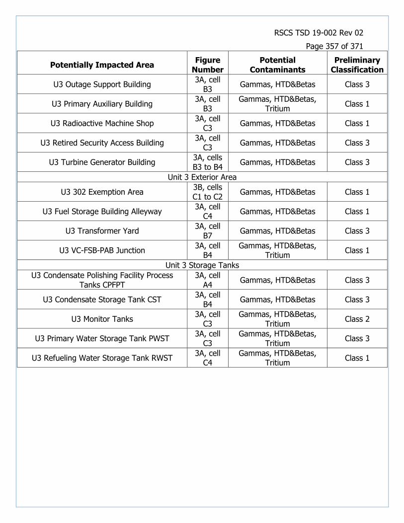
RSCS TSD 19-002 Rev 02
Page 357 of 371
Potentially Impacted Area Figure
Number Potential
Contaminants Preliminary
Classification
U3 Outage Support Building 3A, cell
B3 Gammas, HTD&Betas Class 3
U3 Primary Auxiliary Building 3A, cell
B3 Gammas, HTD&Betas,
Tritium Class 1
U3 Radioactive Machine Shop 3A, cell
C3 Gammas, HTD&Betas Class 1
U3 Retired Security Access Building 3A, cell
C3 Gammas, HTD&Betas Class 3
U3 Turbine Generator Building 3A, cells B3 to B4
Gammas, HTD&Betas Class 3
Unit 3 Exterior Area
U3 302 Exemption Area 3B, cells C1 to C2
Gammas, HTD&Betas Class 1
U3 Fuel Storage Building Alleyway 3A, cell
C4 Gammas, HTD&Betas Class 1
U3 Transformer Yard 3A, cell
B7 Gammas, HTD&Betas Class 3
U3 VC-FSB-PAB Junction 3A, cell
B4 Gammas, HTD&Betas,
Tritium Class 1
Unit 3 Storage Tanks
U3 Condensate Polishing Facility Process Tanks CPFPT
3A, cell A4
Gammas, HTD&Betas Class 3
U3 Condensate Storage Tank CST 3A, cell
B4 Gammas, HTD&Betas Class 3
U3 Monitor Tanks 3A, cell
C3 Gammas, HTD&Betas,
Tritium Class 2
U3 Primary Water Storage Tank PWST 3A, cell
C3 Gammas, HTD&Betas,
Tritium Class 3
U3 Refueling Water Storage Tank RWST 3A, cell
C4 Gammas, HTD&Betas,
Tritium Class 1

RSCS TSD 19-002 Rev 02
Page 358 of 371
D. Document Figures
Figure 1: Location of the Indian Point Energy Center

RSCS TSD 19-002 Rev 02
Page 359 of 371
Figure 2: Location of Parcel Boundaries at the Indian Point Energy Center

RSCS TSD 19-002 Rev 02
Page 360 of 371
Figure 3A: Locations of Facilities at the Indian Point Energy Center

RSCS TSD 19-002 Rev 02
Page 361 of 371
Figure 3B: Locations of Facilities at the Indian Point Energy Center

RSCS TSD 19-002 Rev 02
Page 362 of 371
Figure 3C: Locations of Facilities at the Indian Point Energy Center

RSCS TSD 19-002 Rev 02
Page 363 of 371
Figure 4: Locations and Preliminary Classifications of Hazardous Material Storage Areas and Transformers in the Area of Units 1 and 2 at Indian Point Energy Center

RSCS TSD 19-002 Rev 02
Page 364 of 371
Figure 5: Locations and Preliminary Classifications of Hazardous Material Storage Areas and Transformers in the Area of Unit 3 at Indian Point Energy Center
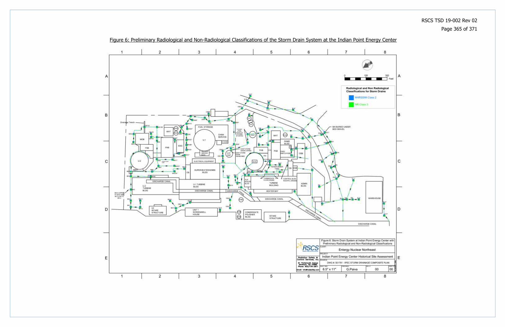
RSCS TSD 19-002 Rev 02
Page 365 of 371
Figure 6: Preliminary Radiological and Non-Radiological Classifications of the Storm Drain System at the Indian Point Energy Center

RSCS TSD 19-002 Rev 02
Page 366 of 371
Figure 7A: Preliminary Non-Radiological Classifications of Facilities at the Indian Point Energy Center

RSCS TSD 19-002 Rev 02
Page 367 of 371
Figure 7B: Preliminary Non-Radiological Classifications of Facilities at the Indian Point Energy Center
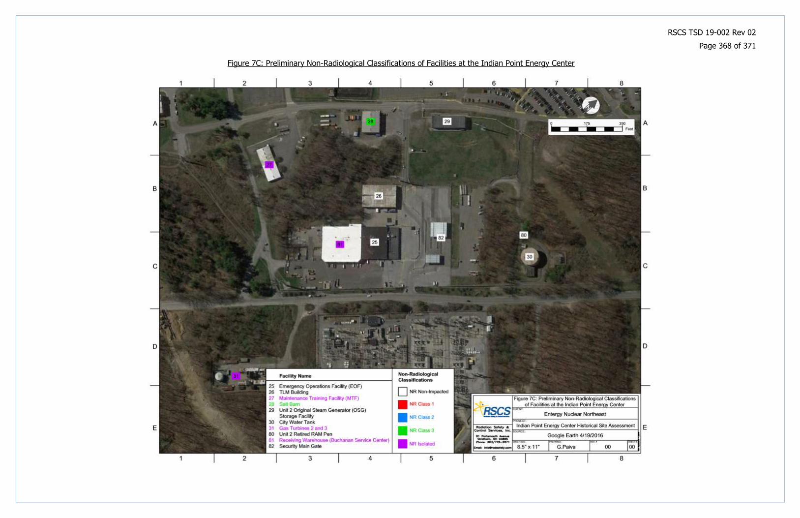
RSCS TSD 19-002 Rev 02
Page 368 of 371
Figure 7C: Preliminary Non-Radiological Classifications of Facilities at the Indian Point Energy Center

RSCS TSD 19-002 Rev 02
Page 369 of 371
Figure 8A: Preliminary Radiological Classifications of Facilities at the Indian Point Energy Center

RSCS TSD 19-002 Rev 02
Page 370 of 371
Figure 8B: Preliminary Radiological Classifications of Facilities at the Indian Point Energy Center

RSCS TSD 19-002 Rev 02
Page 371 of 371
Figure 8C: Preliminary Radiological Classifications of Facilities at the Indian Point Energy Center


![Collaborative Literature Search System: An Intelligence ... › ws › files › 77826767 › Dobrkovic... · guidelines [11], emphasizing different literature-search strategies,](https://img.pdfslide.us/doc/110x75/5f183f89b4a6a61c5c2fd924/collaborative-literature-search-system-an-intelligence-a-ws-a-files-a.jpg)