Embed Size (px)
Citation preview
1
2
SEALUR, LTD.
According to statistics, 50% of all o� -schedule shutdowns, accidents and re-pairs of equipment occur due to seal failure of the detachable joints, whereas the cost of seals is less than 0.01% of the equipment cost.
To solve the tightness problems SEALUR, Ltd. manufactures and supplies a wide range of up-to-date seals made of thermal-expanded graphite (TEG) and other asbestos-free materials, including:
TEG foil;
graphite sheet materials;
TEG tapes;
reinforced or not reinforced, metal-based TEG gaskets or spiral wound gaskets;
gland sealing TEG rings;
packing made of thermal-expanded graphite, carbon or aramid fibers, PTEE or other materials;
small-size facilities: SVU KONTUR machines to cut out gaskets and ET-ALON rules to cut packing.
Seals produced by SEALUR, Ltd are widely used in the power, automo-tive, chemical, oil refining, aviation, space and other industries because of a unique combination of service properties:
operating temperature range: from -240°C to +500°C in the air; Up to +650°C in water vapor; Up to +2000°C in inert atmosphere
operating pressure: from 10-4 to 40,0 MPa;
рН: from 0 to 14;
slip velocity: up to 25 m/sec
3
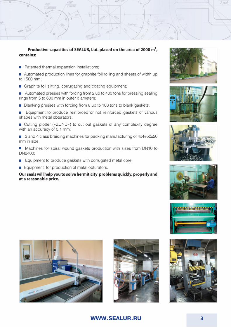
Productive capacities of SEALUR, Ltd. placed on the area of 2000 m², contains:
Patented thermal expansion installations;
Automated production lines for graphite foil rolling and sheets of width up to 1500 mm;
Graphite foil slitting, corrugating and coating equipment;
Automated presses with forcing from 2 up to 400 tons for pressing sealing rings from 5 to 680 mm in outer diameters;
Blanking presses with forcing from 8 up to 100 tons to blank gaskets;
Equipment to produce reinforced or not reinforced gaskets of various shapes with metal obturators;
Cutting plotter («ZUND») to cut out gaskets of any complexity degree with an accuracy of 0,1 mm;
3 and 4 class braiding machines for packing manufacturing of 4x4÷50x50 mm in size
Machines for spiral wound gaskets production with sizes from DN10 to DN2400;
Equipment to produce gaskets with corrugated metal core;
Equipment for production of metal obturators.
Our seals will help you to solve hermiticity problems quickly, properly and at a reasonable price.
4
SEALUR, LTD.
Thermal-expanded Graphite (TEG) FoilSpecs 5728-003-93978201-2008
Graphite foil is manufactured from the natural eucristalline graphite.
Thermal-expanded graphite foil is rolled graphite material (both reinforced and not reinforced) produced by rolling of thermal-expanded graphite.
Depending on the purpose the foil can:
be of various purity degree (GF-100, GF-200, GF-300, GF-400 and GF-500)
have various reinforcing elements
GF-200 – without reinforcing elements;GF-210 – reinforced with lavsan filament;GF-220 – reinforced with alloyed corrosion-resistant steel wire;GF-230 – reinforced with glass fiber;GF-260 – reinforced with polymer film.
have various modifying coatings and additivesGF-202 – with cladding coating of corrosion-resistant steel foil;GF-203 – with cladding coating of nickel foil;GF-204 – with cladding coating of aluminum foil;GF-205, GL-206 – with inhibitors of various actions added;GF-207 – with anti-adhesive additive
be manufactured by various methodsGF-2000 – without sticky coat (may be also designated as GF-200);GF-2001 – self-adhesive foil (with sticky (alive) adhesive).The foil is produced in rolls 400 mm, 1000 mm and 1500 mm wide, and up to 150 m long.
Content of Controlled Additives in Foil
GF-200 foil, 1000 mm wide
TEG Foil Mark TEG Foil Pur i tyDe-
gree
Impurity index
GF-100 1 ≤0,07 ≤20
≤20
≤50
≤50
≤70
≤0,08
≤0,10
≤0,10
≤0,12
≤ 0,2
≤ 0,5
Ash, %
Clˉ, ppm
S,%
2
3
4
5
GF-200
GF-300
GF-400
GF-500
1,0±0,1
2,0±0,3
5,0±0,3
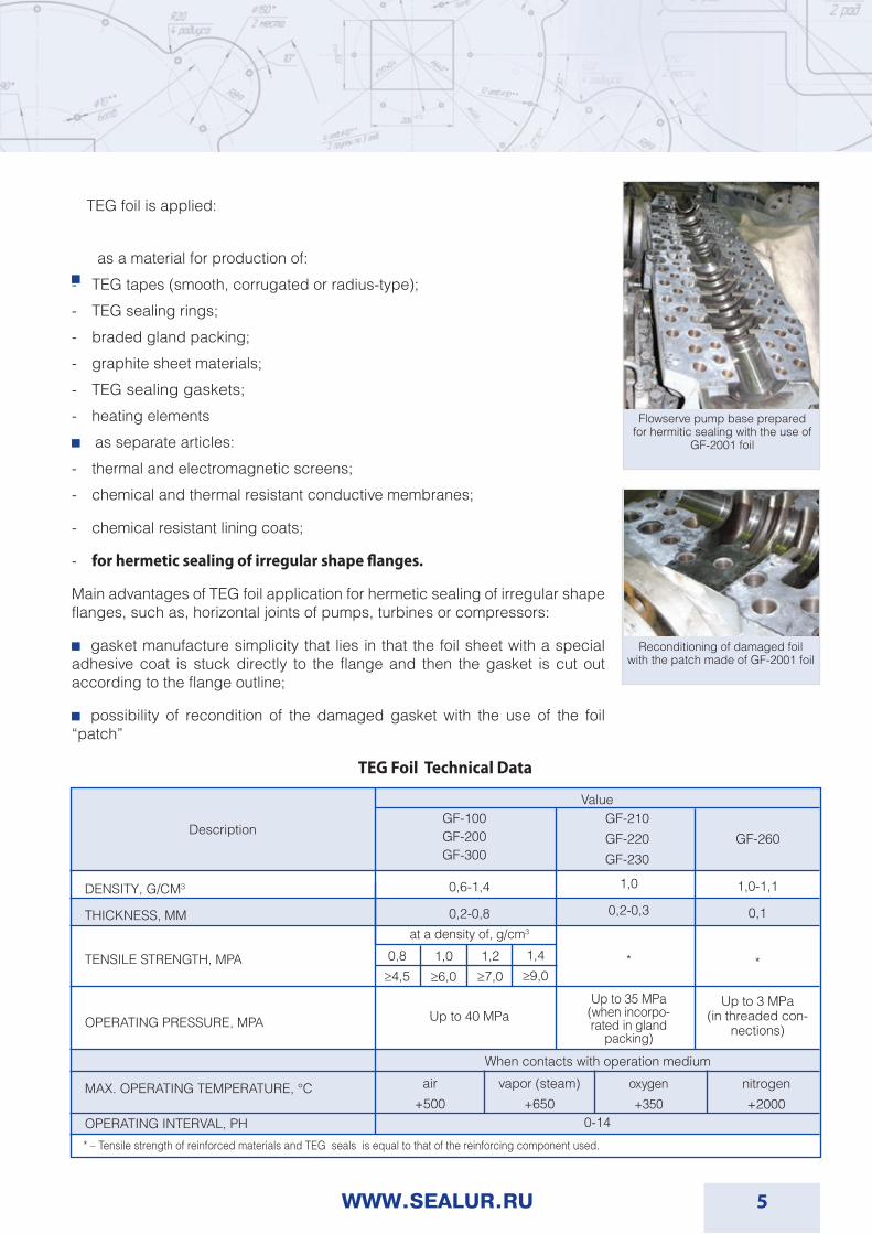
Self-adhesive foil GF-2001
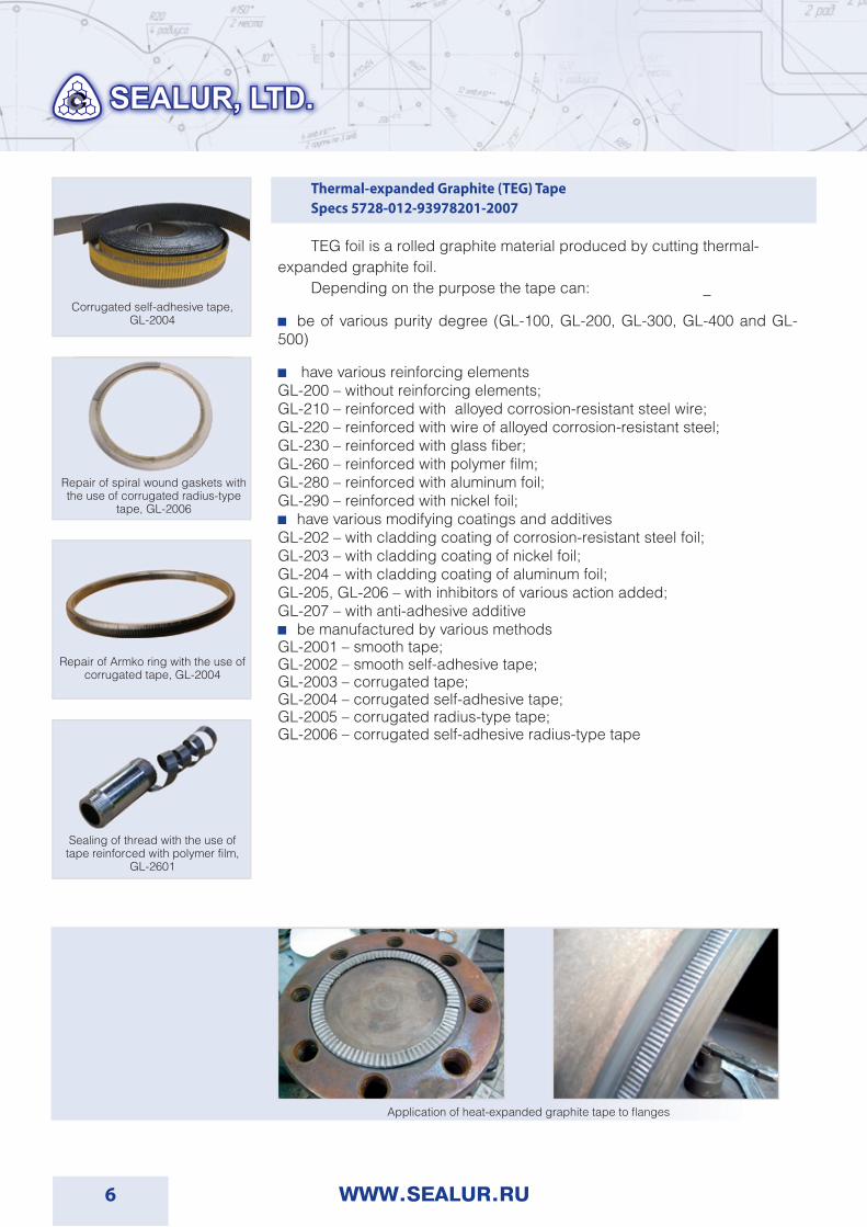
Foil-rolling line, LPF-1500
GF-200 foil, 1000 mm wide
5
TEG foil is applied:
as a material for production of:
- TEG tapes (smooth, corrugated or radius-type);
- TEG sealing rings;
- braded gland packing;
- graphite sheet materials;
- TEG sealing gaskets;
- heating elements
as separate articles:
- thermal and electromagnetic screens;
- chemical and thermal resistant conductive membranes;
- chemical resistant lining coats;
- for hermetic sealing of irregular shape � anges.
Main advantages of TEG foil application for hermetic sealing of irregular shape flanges, such as, horizontal joints of pumps, turbines or compressors:
gasket manufacture simplicity that lies in that the foil sheet with a special adhesive coat is stuck directly to the flange and then the gasket is cut out according to the flange outline;
possibility of recondition of the damaged gasket with the use of the foil “patch”
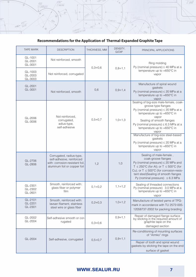
Flowserve pump base prepared for hermitic sealing with the use of
GF-2001 foil
Reconditioning of damaged foil with the patch made of GF-2001 foil
* – Tensile strength of reinforced materials and TEG seals is equal to that of the reinforcing component used.
0,6-1,4
0,2-0,8
at a density of, g/cm3
Up to 40 MPa
1,0
0,2-0,3
*
Up to 35 MPa(when incorpo-rated in gland
packing)
1,0-1,1
0,1
*
Up to 3 MPa(in threaded con-
nections)
Description
DENSITY, G/CM3 ��
THICKNESS, MM
TENSILE STRENGTH, MPA
OPERATING PRESSURE, MPA
MAX. OPERATING TEMPERATURE, °C
OPERATING INTERVAL, PH
Value
When contacts with operation medium
0-14
GF-100GF-200GF-300
air
+500
0,8
≥4,5
1,4
≥9,0
1,0
≥6,0
1,2
≥7,0
vapor (steam)
+650
oxygen
+350
nitrogen
+2000
GF-210
GF-220
GF-230
GF-260
TEG Foil Technical Data
6
SEALUR, LTD.
Thermal-expanded Graphite (TEG) TapeSpecs 5728-012-93978201-2007
TEG foil is a rolled graphite material produced by cutting thermal-expanded graphite foil.
Depending on the purpose the tape can:
be of various purity degree (GL-100, GL-200, GL-300, GL-400 and GL-500)
have various reinforcing elementsGL-200 – without reinforcing elements;GL-210 – reinforced with alloyed corrosion-resistant steel wire;GL-220 – reinforced with wire of alloyed corrosion-resistant steel;GL-230 – reinforced with glass fiber;GL-260 – reinforced with polymer film;GL-280 – reinforced with aluminum foil;GL-290 – reinforced with nickel foil;
have various modifying coatings and additivesGL-202 – with cladding coating of corrosion-resistant steel foil;GL-203 – with cladding coating of nickel foil;GL-204 – with cladding coating of aluminum foil;GL-205, GL-206 – with inhibitors of various action added;GL-207 – with anti-adhesive additive
be manufactured by various methods GL-2001 – smooth tape;GL-2002 – smooth self-adhesive tape;GL-2003 – corrugated tape;GL-2004 – corrugated self-adhesive tape;GL-2005 – corrugated radius-type tape;GL-2006 – corrugated self-adhesive radius-type tape
Corrugated self-adhesive tape, GL-2004
Repair of spiral wound gaskets with the use of corrugated radius-type
tape, GL-2006
Repair of Armko ring with the use of corrugated tape, GL-2004
Sealing of thread with the use of tape reinforced with polymer film,
GL-2601
Application of heat-expanded graphite tape to flanges
7
Recommendations for the Application of Thermal-Expanded Graphite Tape
0,3÷0,6
0,6
0,5÷0,7
1,2
0,1÷0,2
0,2÷0,3
0,3÷0,6
0,5÷0,7
0,8÷1,1
0,9÷1,4
1,0÷1,3
1,0
1,1÷1,2
1,0÷1,2
0,9÷1,1
0,9÷1,1
GL-1001GL-2001GL-3001
GL-1003GL-2003GL-3003
GL-2001GL-3001
GL-2006GL-3006
GL-2706GL-2806
GL-2301GL-2302GL-2601
GL-2101GL-2201GL-2301
GL-2002GL-2004
GL-2004
Not reinforced, smooth
Not reinforced, corrugated
Not reinforced, smooth
Not reinforced,corrugated, adius-type,
self-adhesive
Corrugated, radius-type, self-adhesive, reinforced
with: corrosion-resistant foil, aluminum foil or copper foil
Smooth, reinforced with: glass fiber or polymer
film
Smooth, reinforced with: lavsan filament, stainless steel wire or glass fiber
Self-adhesive smooth or cor-rugated
Self-adhesive, corrugated
PRINCIPAL APPLICATIONSDESCRIPTIONTAPE MARK THICKNESS, MM DENSITY,G/CM3�
Ring moldingРу (nominal pressure) ≤ 40 MPa at a
temperature up to +650°C invapor
Manufacture of spiral wound gaskets
Ру (nominal pressure) ≤ 20 MPa at a temperature up to +650°C in
vapor Sealing of big-size male-female, coak-
groove type flanges Ру (nominal pressure) ≤ 20 MPa at a
temperature up to +650°C in vapor
Sealing of smooth flangesРу (nominal pressure) ≤ 6.3 MPa at a
temperature up to +650°C in vapor
Manufacture of big-size steel-based gaskets
Ру (nominal pressure) ≤ 20 MPa at a temperature up to +650°C in
vapor
Sealing of male-female ,coak-groove flanges
Ру (nominal pressure) ≤ 20 MPa and T�≤ 250°C (for Al); or T�≤ 500°C (for
Cu), or T�≤ 500°C (for corrosion-resis-tant steel)Sealing of smooth flangesРу (nominal pressure) �≤ 6.3 MPa
Sealing of threaded connectionsРу (nominal pressure) �3.0 MPa at a
temperature up to +650°C in
vapor
Manufacture of twisted yarns of TPG-
mark in accordance with TU 2572-005-
12058737-2002 for packing braiding
Repair of damaged flange surface by sticking in the required amount of
graphite tape on the
damaged section
Re-conditioning of mounting surfaces of “Armko” rings
Repair of tooth and spiral wound gaskets by sticking the tape on the end
surface of gasket
8
SEALUR, LTD.
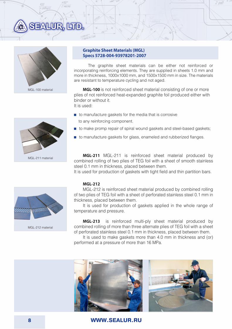
MGL-100 material
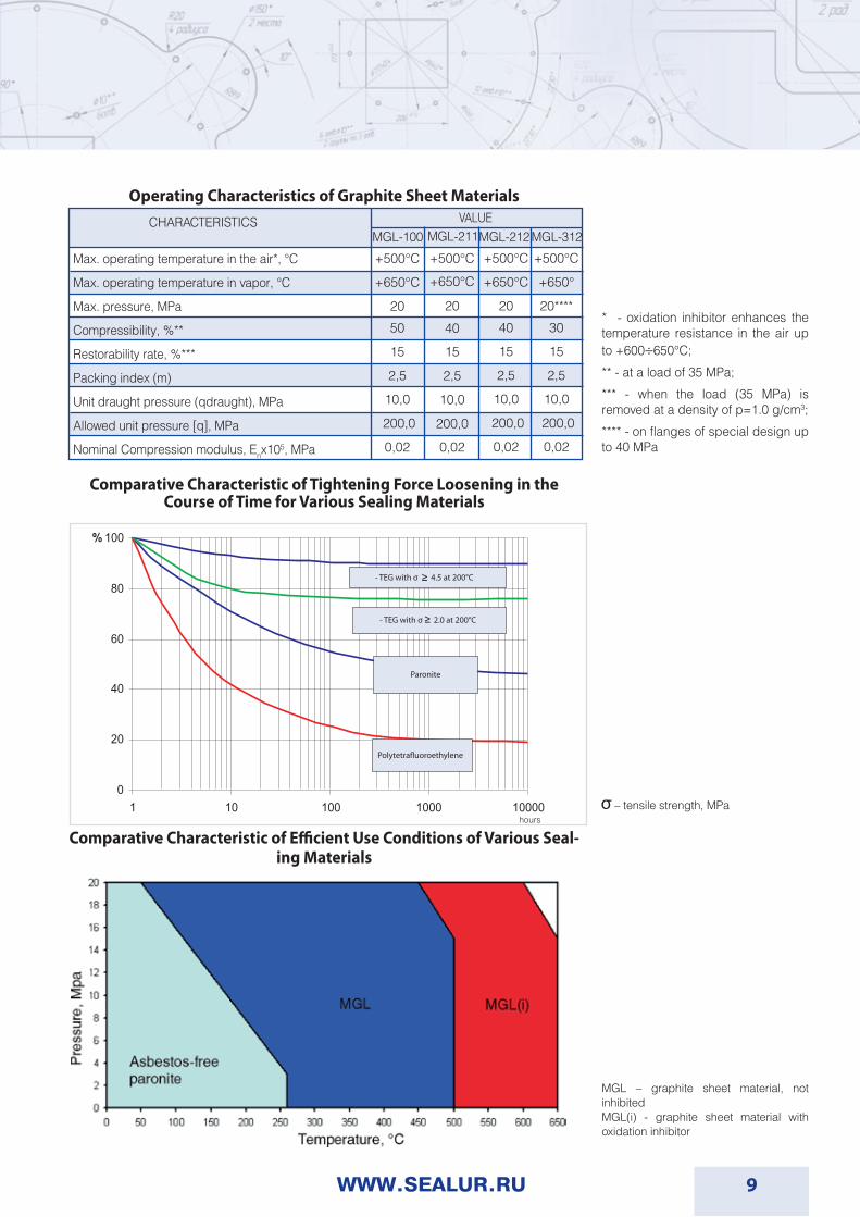
MGL-211 material
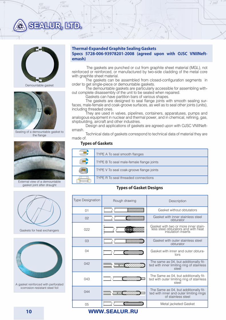
MGL-212 material
Graphite Sheet Materials (MGL)Specs 5728-004-93978201-2007
The graphite sheet materials can be either not reinforced or incorporating reinforcing elements. They are supplied in sheets 1.0 mm and more in thickness, 1000x1000 mm, and 1500x1500 mm in size. The materials are resistant to temperature cycling and not aged.
MGL-100 is not reinforced sheet material consisting of one or more plies of not reinforced heat-expanded graphite foil produced either with binder or without it. It is used:
to manufacture gaskets for the media that is corrosive
to any reinforcing component.
to make promp repair of spiral wound gaskets and steel-based gaskets;
to manufacture gaskets for glass, enameled and rubberized flanges.
MGL-211 MGL-211 is reinforced sheet material produced by combined rolling of two plies of TEG foil with a sheet of smooth stainless steel 0.1 mm in thickness, placed between them.It is used for production of gaskets with tight field and thin partition bars.
MGL-212 MGL-212 is reinforced sheet material produced by combined rolling
of two plies of TEG foil with a sheet of perforated stainless steel 0.1 mm in thickness, placed between them.
It is used for production of gaskets applied in the whole range of temperature and pressure.
MGL-213 is reinforced multi-ply sheet material produced by combined rolling of more than three alternate plies of TEG foil with a sheet of perforated stainless steel 0.1 mm in thickness, placed between them.
It is used to make gaskets more than 4.0 mm in thickness and (or) performed at a pressure of more than 16 MPa.
9
Operating Characteristics of Graphite Sheet Materials
Comparative Characteristic of Tightening Force Loosening in the Course of Time for Various Sealing Materials
Comparative Characteristic of E� cient Use Conditions of Various Seal-ing Materials
+500°С
+650°С
20
50
15
2,5
10,0
200,0
0,02
+500°С
+650°С
20
40
15
2,5
10,0
200,0
0,02
+500°С
+650°
20****
30
15
2,5
10,0
200,0
0,02
CHARACTERISTICS
Max. operating temperature in the air*, °C
Max. operating temperature in vapor, °C
Max. pressure, MPa
Compressibility, %**
Restorability rate, %***
Packing index (m)
Unit draught pressure (qdraught), MPa
Allowed unit pressure [q], MPa
Nominal Compression modulus, Enx105, MPa
MGL-100
VALUE
MGL-212MGL-312MGL-211
+500°С
+650°С
20
40
15
2,5
10,0
200,0
0,02
* - oxidation inhibitor enhances the temperature resistance in the air up to +600÷650°C;
** - at a load of 35 MPa;
*** - when the load (35 MPa) is removed at a density of p=1.0 g/cm3;
**** - on flanges of special design up to 40 MPa
– tensile strength, MPa
MGL – graphite sheet material, not inhibitedMGL(i) - graphite sheet material with oxidation inhibitor
- TEG with σ 4.5 at 200°С
- TEG with σ 2.0 at 200°С
Paronite
Polytetra� uoroethylene�
hours
10
SEALUR, LTD.
Thermal-Expanded Graphite Sealing GasketsSpecs 5728-006-93978201-2008 (agreed upon with OJSC VNIINeft-emash)
The gaskets are punched or cut from graphite sheet material (MGL), not reinforced or reinforced, or manufactured by two-side cladding of the metal core with graphite sheet material.
The gaskets can be assembled from closed-configuration segments in order to get single-piece or demountable gaskets.
The demountable gaskets are particularly accessible for assembling with-out complete disassembly of the unit to be sealed when repaired.
Gaskets can have partition bars of various shapes. The gaskets are designed to seal flange joints with smooth sealing sur-
faces, male-female and coak-groove surfaces, as well as to seal other joints (units), including threaded ones.
They are used in valves, pipelines, containers, apparatuses, pumps and analogous equipment in nuclear and thermal power, and in chemical, refining, gas, shipbuilding, aircraft and other industries.
Design and applications of gaskets are agreed upon with OJSC VNIINeft-emash.
Technical data of gaskets correspond to technical data of material they are made of.
Types of Gaskets
Types of Gasket Designs
Gaskets for heat exchangers
TYPE A To seal smooth flanges
TYPE B To seal male-female flange joints
TYPE V To seal coak-groove flange joints
TYPE R To seal threaded connections
Description
Gasket without obtutators
Gasket with inner stainless steel obturator
Gasket with two or more inner stain-less steel obturators and with heat
insulation inserts
Gasket with outer stainless steel obturator
Gasket with inner and outer obtura-tors
The same as 04, but additionally fit-ted with inner limiting ring of stainless
steel
The Same as 04, but additionally fit-ted with outer limiting ring of stainless
steel
The Same as 04, but additionally fit-ted with inner and outer limiting rings
of stainless steel
Metal jacketed Gasket
Rough drawingType Designation
01
02
022
03
04
042
043
044
05
A gasket reinforced with perforated icorrosion-resistant steel foil
Demountable gasket
Seating of a demountable gasket to the flange
External view of a demountable gasket joint after draught
11
Gaskets for Threaded Connections SealingSpecs 5728-006-93978201-2008
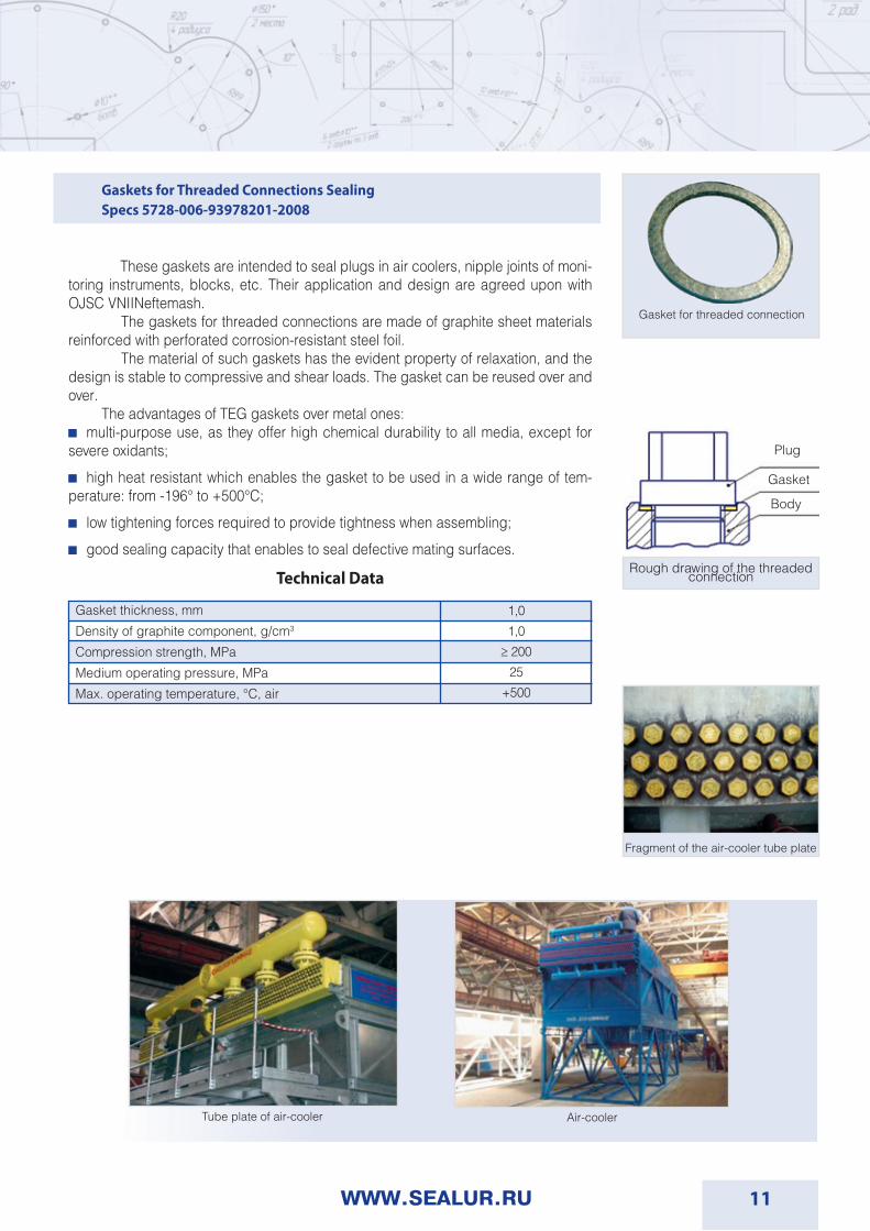
These gaskets are intended to seal plugs in air coolers, nipple joints of moni-toring instruments, blocks, etc. Their application and design are agreed upon with OJSC VNIINeftemash.
The gaskets for threaded connections are made of graphite sheet materials reinforced with perforated corrosion-resistant steel foil.
The material of such gaskets has the evident property of relaxation, and the design is stable to compressive and shear loads. The gasket can be reused over and over.
The advantages of TEG gaskets over metal ones:multi-purpose use, as they offer high chemical durability to all media, except for
severe oxidants;
high heat resistant which enables the gasket to be used in a wide range of tem-perature: from -196° to +500°C;
low tightening forces required to provide tightness when assembling;
good sealing capacity that enables to seal defective mating surfaces.
Technical Data
Gasket for threaded connection
Fragment of the air-cooler tube plate
Gasket thickness, mm
Density of graphite component, g/cm3�
Compression strength, MPa
Medium operating pressure, MPa
Max. operating temperature, °C, air
1,0
1,0
≥ 200
25
+500
Rough drawing of the threaded connection
Tube plate of air-cooler Air-cooler
Plug
Gasket
Body
12
SEALUR, LTD.
Drawing of gasket for plotter
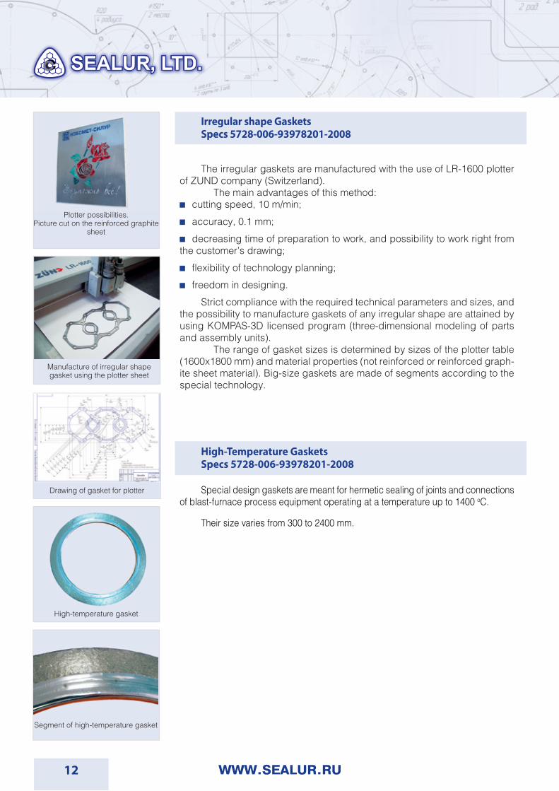
Plotter possibilities.Picture cut on the reinforced graphite
sheet
Manufacture of irregular shapegasket using the plotter sheet
Irregular shape GasketsSpecs 5728-006-93978201-2008
The irregular gaskets are manufactured with the use of LR-1600 plotter of ZUND company (Switzerland).
The main advantages of this method:cutting speed, 10 m/min;
accuracy, 0.1 mm;
decreasing time of preparation to work, and possibility to work right from the customer’s drawing;
flexibility of technology planning;
freedom in designing.
Strict compliance with the required technical parameters and sizes, and the possibility to manufacture gaskets of any irregular shape are attained by using KOMPAS-3D licensed program (three-dimensional modeling of parts and assembly units).
The range of gasket sizes is determined by sizes of the plotter table (1600x1800 mm) and material properties (not reinforced or reinforced graph-ite sheet material). Big-size gaskets are made of segments according to the special technology.
High-Temperature GasketsSpecs 5728-006-93978201-2008
Special design gaskets are meant for hermetic sealing of joints and connections of blast-furnace process equipment operating at a temperature up to 1400 oC.
Their size varies from 300 to 2400 mm.
High-temperature gasket
Segment of high-temperature gasket
13
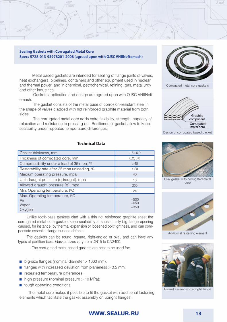
Sealing Gaskets with Corrugated Metal Core Specs 5728-013-93978201-2008 (agreed upon with OJSC VNIINeftemash)
Metal based gaskets are intended for sealing of flange joints of valves, heat exchangers, pipelines, containers and other equipment used in nuclear and thermal power, and in chemical, petrochemical, refining, gas, metallurgy and other industries. Gaskets application and design are agreed upon with OJSC VNIINeft-emash. The gasket consists of the metal base of corrosion-resistant steel in the shape of valves cladded with not reinforced graphite material from both sides. The corrugated metal core adds extra flexibility, strength, capacity of relaxation and resistance to pressing-out. Resilience of gasket allow to keep sealability under repeated temperature differences.
Technical Data
big-size flanges (nominal diameter > 1000 mm);
flanges with increased deviation from planeness > 0.5 mm;
repeated temperature differences;
high pressure (nominal pressure > 10 MPa);
tough operating conditions.
The metal core makes it possible to fit the gasket with additional fastening elements which facilitate the gasket assembly on upright flanges.
Corrugated metal core gaskets
Graphitecomponent
Corrugatedmetal core
Design of corrugated based gasket
Unlike tooth-base gaskets clad with a thin not reinforced graphite sheet the corrugated metal core gaskets keep sealability at substantially big flange opening caused, for instance, by thermal expansion or loosened bolt tightness, and can com-pensate essential flange surface defects.
The gaskets can be round, square, right-angled or oval, and can have any types of partition bars. Gasket sizes vary from DN15 to DN2400.
The corrugated metal based gaskets are best to be used for:
Gasket thickness, mmThickness of corrugated core, mmCompressibility under a load of 35 mpa, %Restorability rate after 35 mpa unloading, %Medium operating pressure, mpaUnit draught pressure (qdraught), mpaAllowed draught pressure [q], mpaMin. Operating temperature, toCMax. Operating temperature, toCAir Vapor Oxygen
1,6 : 6,0
0,2; 0,8
≥ 40
≥ 20
40
10
200
- 240
+500+650+350
Oval gasket with corrugated metal core
Additional fastening element
Gasket assembly to upright flange
Graphitecomponent
Corrugatedmetal core
14
SEALUR, LTD.
Attention! Assembling of all types of thermal-expanded graphite gaskets it is not allowed to use liquid greases.
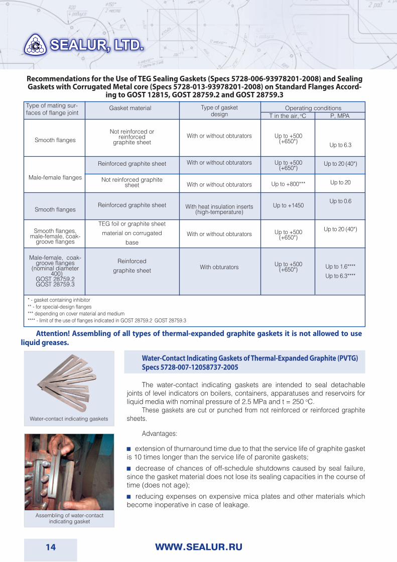
Water-contact indicating gaskets
Assembling of water-contact indicating gasket
Water-Contact Indicating Gaskets of Thermal-Expanded Graphite (PVTG)Specs 5728-007-12058737-2005
The water-contact indicating gaskets are intended to seal detachable joints of level indicators on boilers, containers, apparatuses and reservoirs for liquid media with nominal pressure of 2.5 MPa and t = 250 oC.
These gaskets are cut or punched from not reinforced or reinforced graphite sheets.
Advantages:
extension of thurnaround time due to that the service life of graphite gasket is 10 times longer than the service life of paronite gaskets;
decrease of chances of off-schedule shutdowns caused by seal failure, since the gasket material does not lose its sealing capacities in the course of time (does not age);
reducing expenses on expensive mica plates and other materials which become inoperative in case of leakage.
* - gasket containing inhibitor** - for special-design flanges*** depending on cover material and medium**** - limit of the use of flanges indicated in GOST 28759.2�GOST 28759.3
Up to +500 (+650*)
Up to +500 (+650*)
Up to +800***
Up to +1450
Up to +500 (+650*)
Up to +500 (+650*)
Up to 6.3
Up to 20 (40*)
Up to 20
Up to 0.6
Up to 20 (40*)
Up to 1.6****
Up to 6.3****
Type of mating sur-faces of flange joint
Gasket material Type of gasket design
Smooth flanges
Male-female flanges
Smooth flanges
Smooth flanges, male-female, coak-
groove flanges
Male-female, coak-groove flanges
(nominal diameter �400)
GOST 28759.2GOST 28759.3
Operating conditionsT in the air, oC P, MPA
Recommendations for the Use of TEG Sealing Gaskets (Specs 5728-006-93978201-2008) and Sealing Gaskets with Corrugated Metal core (Specs 5728-013-93978201-2008) on Standard Flanges Accord-
ing to GOST 12815, GOST 28759.2 and GOST 28759.3
With or without obturators
With or without obturators
With or without obturators
With heat insulation inserts (high-temperature)
With or without obturators
With obturators
Not reinforced or reinforced
graphite sheet
Reinforced graphite sheet
Not reinforced graphite sheet
Reinforced graphite sheet
TEG foil or graphite sheet
material on corrugated
base
Reinforced
graphite sheet
15
Spiral Wound Gaskets (SNP)Specs 3689-010-9297201-2008
The spiral wound gaskets are manufactured by winding alternating layers of base (V-profiled tape of cold-rolled corrosion-resistant steel) and filling agent (tape thermal-expanded graphite or polytetrafluorethylene (PTFE) around the mandrel. The spiral wound gaskets are operated at the nominal pressure (PN) of 10-4 – 20.0 MPa, and nominal bore (DN) of 10-2500. Design of spiral wound gaskets manufactured by Novomet-SEALUR Ltd meets all requirements of GOST (State Standard) R 52376, OST (Branch Standard) 26.260.454, and ANSI/ASME B 16.20.
The Type of spiral wound gasket depends on the type of mating sur-faces of � ange joint
The filling material is chosen according to the operating conditions: TEG tape (foil) (denoted by 3) is used in corrosive media (acids, alkalies, oxidants, petroleum products, organic solvents) at a temperature up to 500�0C; TEG tape (foil) (denoted by 4) is used in noncorrosive media (vapour, residue gases, heavy petroleum products) at a temperature up to 600 0C; and polytetrafluorethylene (PTFE) tape F-4 (denoted by 5) is used in corrosive media (acids, alkalies and solvents) at a temperature up to + 200 0C.
Attention! Increase in the gasket diameter results in reduction of as-sembling and transport strength. For sizes over DN1000 it is advisable to use gaskets with corrugated metal core.
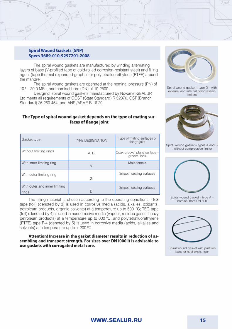
Spiral wound gasket – type D – with external and internal compression
limiters
Spiral wound gasket – types A and B – without compression limiter
Spiral wound gasket – type A – nominal bore DN 800
Spiral wound gasket with partition bars for heat exchanger
Gasket type
Without limiting rings
With inner limiting ring
With outer limiting ring
With outer and inner limiting
rings
TYPE DESIGNATION
A, B
V
G
D
Type of mating surfaces of flange joint
Coak-groove, plane surface – groove, lock
Male-female
Smooth sealing surfaces
Smooth sealing surfaces
16
SEALUR, LTD.
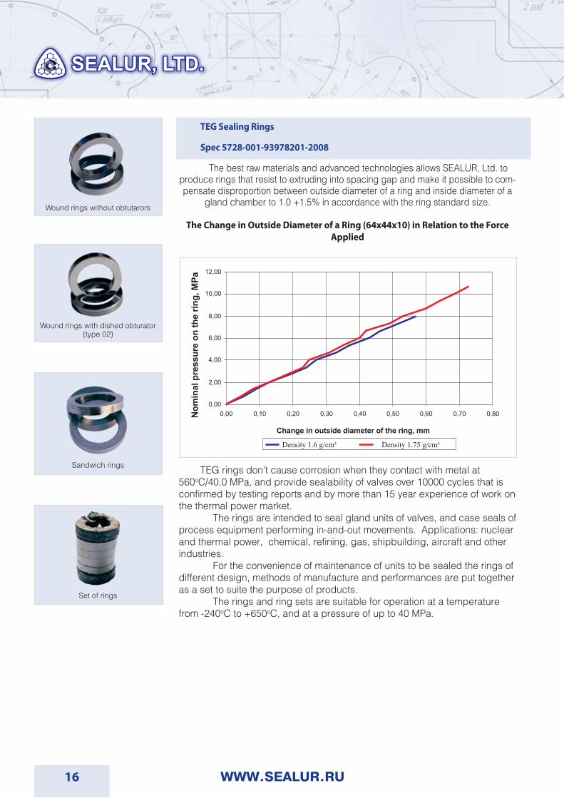
TEG Sealing Rings
Spec 5728-001-93978201-2008
The best raw materials and advanced technologies allows SEALUR, Ltd. to produce rings that resist to extruding into spacing gap and make it possible to com-pensate disproportion between outside diameter of a ring and inside diameter of a
gland chamber to 1.0 +1.5% in accordance with the ring standard size.
The Change in Outside Diameter of a Ring (64x44x10) in Relation to the Force Applied
The rings in heat-expanded graphite don’t cause corrosion when con
TEG rings don’t cause corrosion when they contact with metal at 560oC/40.0 MPa, and provide sealability of valves over 10000 cycles that is confirmed by testing reports and by more than 15 year experience of work on the thermal power market.
The rings are intended to seal gland units of valves, and case seals of process equipment performing in-and-out movements. Applications: nuclear and thermal power, chemical, refining, gas, shipbuilding, aircraft and other industries.
For the convenience of maintenance of units to be sealed the rings of different design, methods of manufacture and performances are put together as a set to suite the purpose of products.
The rings and ring sets are suitable for operation at a temperature from -240oC to +650oC, and at a pressure of up to 40 MPa.
Wound rings without obtutarors
Wound rings with dished obturator (type 02)
Sandwich rings
Set of rings
Nom
inal
pre
ssur
e on
the
ring,
MPa
Change in outside diameter of the ring, mm
Density 1.6 g/cm³ Density 1.75 g/cm³
17
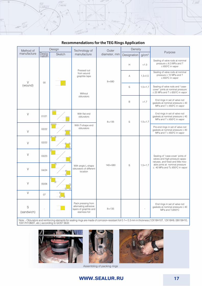
Recommendations for the TEG Rings Application
Method of manufacture
V(wound)
V
V
V
V
V
V
V
S
(sandwich)
00
01/21
02/22
02/22
03/23
04/24
05/06
07
-
Design DensityPurpose
Sealing of valve rods at nominal pressure ≤ 6.3 MPa and T
≤ 650oC in vapor
Sealing of valve rods at nominal pressure ≤ 10 MPa and T
≤ 650oC in vapor
Sealing of valve rods and “case-cover” joints at nominal pressure ≤ 25 MPa and T ≤ 650oC in vapor
End rings in set of valve rod gaskets at nominal pressure ≤ 40
MPa and T ≤ 650oC in vapor
End rings in set of valve rod gaskets at nominal pressure ≤ 40
MPa and T ≤ 650oC in vapor
Pre-end rings in set of valve rod gaskets at nominal pressure ≤ 40
MPa and T ≤ 650oC in vapor
Sealing of “case-cover’ joints of valves and high-pressure appa-ratuses, and fixed and little mov-able joints at nominal pressure
≤ 40 MPa and T≤ 650oC in vapor
End rings in set of valve rod gaskets at nominal pressure ≤ 40
MPa and T≤650oC
Technology of manufacture
Outerdiameter, mmDesig-
nation DesignationSketch g/cm3
<1.3
1,3 :1,5
1,5 : 1,7
>1,7
1,5 : 1,7
1,5 : 1,7
-
H
A
Б
В
Б
Б
8 : 580
8 : 135
140 : 580
8 : 135
Pressed out from wound
graphite tape
Withoutobturators
With flat endobturators
With П-shape end obturators
With angle L-shape obturators of different
location
Pack pressing from alternating adhesive
layers of graphite and stainless foil
Note: - Obturators and reinforcing elements for sealing rings are made of corrosion-resistant foil 0.1 :�0.3 mm in thickness (12X18H10T, 12X18H9, 08X18H10, 10X17H13M3T, etc.) according to GOST 5632.
Assembling of packing rings
18
SEALUR, LTD.
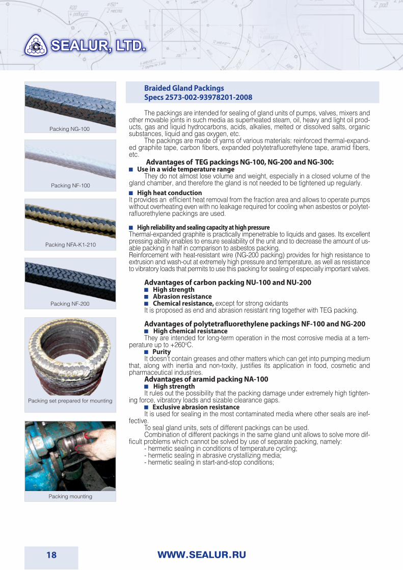
Braided Gland Packings Specs 2573-002-93978201-2008
The packings are intended for sealing of gland units of pumps, valves, mixers and other movable joints in such media as superheated steam, oil, heavy and light oil prod-ucts, gas and liquid hydrocarbons, acids, alkalies, melted or dissolved salts, organic substances, liquid and gas oxygen, etc.
The packings are made of yarns of various materials: reinforced thermal-expand-ed graphite tape, carbon fibers, expanded polytetrafluorethylene tape, aramid fibers, etc.
Advantages of TEG packings NG-100, NG-200 and NG-300:Use in a wide temperature range
They do not almost lose volume and weight, especially in a closed volume of the gland chamber, and therefore the gland is not needed to be tightened up regularly.
High heat conductionIt provides an efficient heat removal from the fraction area and allows to operate pumps without overheating even with no leakage required for cooling when asbestos or polytet-rafluorethylene packings are used.
High reliability and sealing capacity at high pressureThermal-expanded graphite is practically impenetrable to liquids and gases. Its excellent pressing ability enables to ensure sealability of the unit and to decrease the amount of us-able packing in half in comparison to asbestos packing.Reinforcement with heat-resistant wire (NG-200 packing) provides for high resistance to extrusion and wash-out at extremely high pressure and temperature, as well as resistance to vibratory loads that permits to use this packing for sealing of especially important valves.
Advantages of carbon packing NU-100 and NU-200High strengthAbrasion resistanceChemical resistance, except for strong oxidants
It is proposed as end and abrasion resistant ring together with TEG packing.
Advantages of polytetra� uorethylene packings NF-100 and NG-200High chemical resistance
They are intended for long-term operation in the most corrosive media at a tem-perature up to +260oC.
PurityIt doesn’t contain greases and other matters which can get into pumping medium
that, along with inertia and non-toxity, justifies its application in food, cosmetic and pharmaceutical industries.
Advantages of aramid packing NA-100High strength
It rules out the possibility that the packing damage under extremely high tighten-ing force, vibratory loads and sizable clearance gaps.
Exclusive abrasion resistanceIt is used for sealing in the most contaminated media where other seals are inef-
fective.To seal gland units, sets of different packings can be used.Combination of different packings in the same gland unit allows to solve more dif-
ficult problems which cannot be solved by use of separate packing, namely:- hermetic sealing in conditions of temperature cycling;- hermetic sealing in abrasive crystallizing media;- hermetic sealing in start-and-stop conditions;
Packing NG-100
Packing NF-100
Packing NFA-K1-210
Packing NF-200
Packing set prepared for mounting
Packing mounting
19
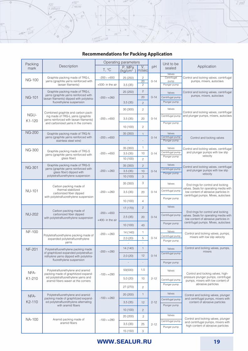
Packing mark
NG-100
NG-101
NGU-
K1-120
NG-200
NG-300
NG-301
NU-101
NU-202
NF-100
NF-201
NFA-
K1-210
NFA-
K2-110
NA-100
Graphite packing made of TRG-L yarns (graphite yarns reinforced with
lavsan filaments)
Graphite packing made of TRG-L yarns (graphite yarns reinforced with
lavsan filaments) dipped with polytetra-fluorethylene suspension
Combined graphite and carbon pack-ing made of TRG-L yarns (graphite
yarns reinforced with lavsan filaments) and carbonized yarns in the corners
Graphite packing made of TRG-N yarns (graphite yarns reinforced with
stainless steel wire)
Graphite packing made of TRG-S yarns (graphite yarns reinforced with
glass fiber)
Graphite packing made of TRG-S yarns (graphite yarns reinforced with
glass fiber) dipped with polytetrafluorethylene suspension
Carbon packing made ofthermal stabilized
carbonized fiber dipped with polytetrafluorethylene suspension
Carbon packing made of carbonized fiber dipped
with polytetrafluorethylene suspension
Polytetrafluorethylene packing made of expanded polytetrafluorethylene
yarns
Polytetrafluorethylene packing made of graphitized expanded polytetrafluo-rethylene yarns dipped with polytetra-
fluorethylene suspension
Polytetrafluorethylene and aramid packing made of graphitized expand-
ed polytetrafluorethylene yarns and aramid fibers waven at the corners
Polytetrafluorethylene and aramid packing made of graphitized expand-ed polytetrafluorethylene alternating
with aramid fibers
Aramid packing made ofaramid fibers
DescriptionOperating parameters
Application
Control and locking valves, centrifugal pumps, mixers, autoclavs
Control and locking valves, centrifugal pumps, mixers, autoclavs
Control and locking valves, centrifugal and plunger pumps, mixers, autoclavs
Control and locking valves
Control and locking valves, centrifugal and plunger pumps with low slip
velocity
Control and locking valves, centrifugal and plunger pumps with low slip
velocity
End rings for control and locking valves. Seals for operating media with
low content of abrasive particles in centrifugal pumps. Mixes, autoclavs
End rings for control and locking valves. Seals for operating media with
low content of abrasive particles in centrifugal pumps. Mixes, autoclavs
Control and locking valves, pumps, mixers with low slip velocity
Control and locking valves, pumps, mixers
Control and locking valves, high-pressure plunger pumps, centrifugal
pumps, mixers with low content of abrasive particles
Control and locking valves, plunger and centrifugal pumps, mixers with
content of abrasive particles
Control and locking valves, plunger and centrifugal pumps, mixers with high content of abrasive particles
Т, °СP, MPa
(kg/cm3�)V,
m/secрН
Unit to be sealed
0-14
0-14
0-14
0-14
0-14
0-14
0-14
0-14
0-14
0-14
2-12
2-12
2-12
2202
2
20
2
2
20
2
1
-
1
10
2
2
10
3
3
20
4
2
20
43
1
5
-
1
12
-
1,5
10
2
1
12
2
2
25
3
25 (250)
3,5 (35)
25 (250)
3,5 (35)
30 (300)
3,5 (35)
10 (100)
35 (350)
-
35 (350)
3,5 (35)
10 (100)
35 (350)
3,5 (35)
10 (100)
35 (350)
3,5 (35)
10 (100)
17 (170)
2,5 (35)
10 (100)
14 (140)
2,0 (20)
-
14 (140)
2,0 (20)
-
50(500)
5,0 (20)
27 (270)
20 (200)
3,5 (35)
10 (100)
20 (200)
3,5 (35)
15 (150)
-200 : +650
+500- in the air
-200 : +260
-200 : +650
-200 : +650
-200 : +650
-200 : +260
-200 : +260
-200 : +650
+400- in the air
-200 : +260
-200 : +280
-100 : +280
-100 : +260
-100 : +280
ValvesCentrifugal
pumpPlunger pump
Valves
Centrifugal pump
Plunger pump
Valves
Centrifugal pump
Plunger pump
ValvesCentrifugal pump
Plunger pump
Valves
Centrifugal pump
Plunger pump
Valves
Centrifugal pump
Plunger pump
Valves
Centrifugal pump
Plunger pump
Valves
Centrifugal pump
Plunger pump
Valves
Centrifugal pump
Plunger pump
Valves
Centrifugal pump
Plunger pump
Valves
Centrifugal pump
Plunger pump
Valves
Centrifugal pump
Plunger pump
Valves
Centrifugal pump
Plunger pump
Recommendations for Packing Application
20
SEALUR, LTD.
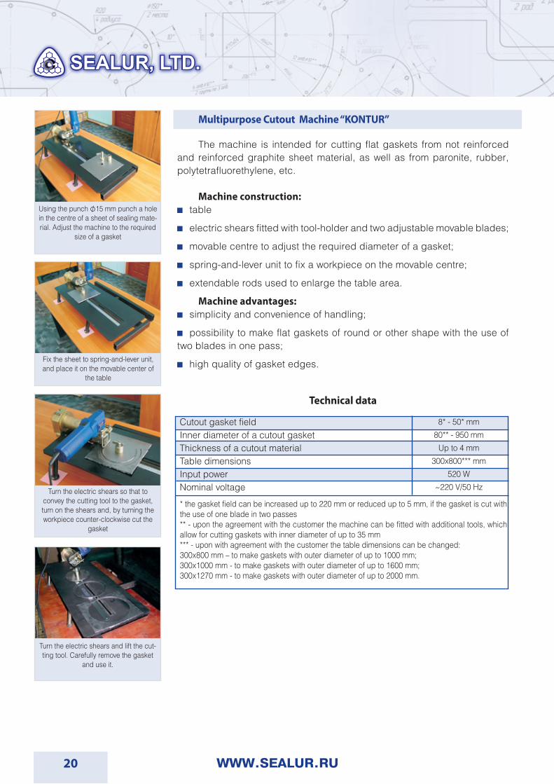
Multipurpose Cutout Machine “KONTUR”
The machine is intended for cutting flat gaskets from not reinforced and reinforced graphite sheet material, as well as from paronite, rubber, polytetrafluorethylene, etc.
Machine construction:table
electric shears fitted with tool-holder and two adjustable movable blades;
movable centre to adjust the required diameter of a gasket;
spring-and-lever unit to fix a workpiece on the movable centre;
extendable rods used to enlarge the table area.
Machine advantages:simplicity and convenience of handling;
possibility to make flat gaskets of round or other shape with the use of two blades in one pass;
high quality of gasket edges.
Technical data
Cutout gasket fieldInner diameter of a cutout gasketThickness of a cutout materialTable dimensionsInput powerNominal voltage
8* - 50* mm
80** - 950 mm
Up to 4 mm
300x800*** mm
520 W
~220 V/50 Hz
* the gasket field can be increased up to 220 mm or reduced up to 5 mm, if the gasket is cut with the use of one blade in two passes** - upon the agreement with the customer the machine can be fitted with additional tools, which allow for cutting gaskets with inner diameter of up to 35 mm*** - upon with agreement with the customer the table dimensions can be changed:300x800 mm – to make gaskets with outer diameter of up to 1000 mm;300x1000 mm - to make gaskets with outer diameter of up to 1600 mm;300x1270 mm - to make gaskets with outer diameter of up to 2000 mm.
Fix the sheet to spring-and-lever unit, and place it on the movable center of
the table
Turn the electric shears so that to convey the cutting tool to the gasket, turn on the shears and, by turning the workpiece counter-clockwise cut the
gasket
Turn the electric shears and lift the cut-ting tool. Carefully remove the gasket
and use it.
Using the punch / 15 mm punch a hole in the centre of a sheet of sealing mate-rial. Adjust the machine to the required
size of a gasket
21
Rule “Etalon”
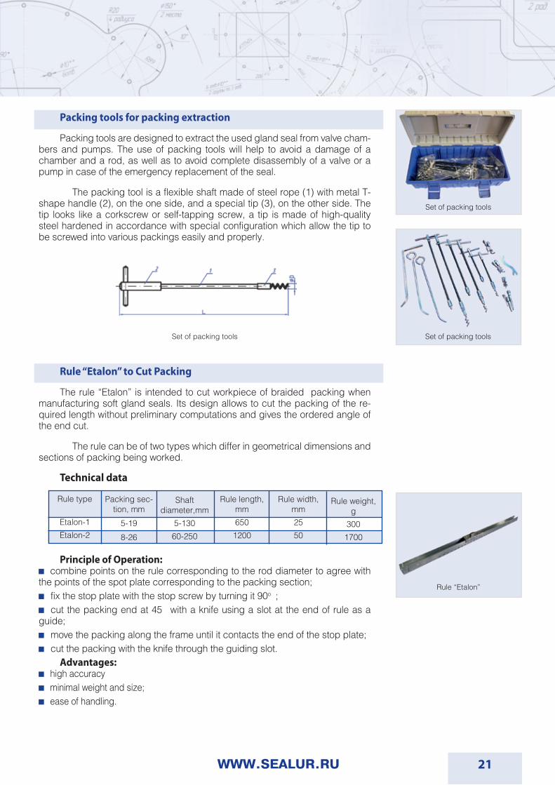
Packing tools for packing extraction
Packing tools are designed to extract the used gland seal from valve cham-bers and pumps. The use of packing tools will help to avoid a damage of a chamber and a rod, as well as to avoid complete disassembly of a valve or a pump in case of the emergency replacement of the seal.
The packing tool is a flexible shaft made of steel rope (1) with metal T-shape handle (2), on the one side, and a special tip (3), on the other side. The tip looks like a corkscrew or self-tapping screw, a tip is made of high-quality steel hardened in accordance with special configuration which allow the tip to be screwed into various packings easily and properly.
Rule “Etalon” to Cut Packing
The rule “Etalon” is intended to cut workpiece of braided packing when manufacturing soft gland seals. Its design allows to cut the packing of the re-quired length without preliminary computations and gives the ordered angle of the end cut.
The rule can be of two types which differ in geometrical dimensions and sections of packing being worked.
Technical data
Principle of Operation:combine points on the rule corresponding to the rod diameter to agree with
the points of the spot plate corresponding to the packing section;fix the stop plate with the stop screw by turning it 90o�;cut the packing end at 45� with a knife using a slot at the end of rule as a
guide;move the packing along the frame until it contacts the end of the stop plate;cut the packing with the knife through the guiding slot.
Advantages:high accuracyminimal weight and size;ease of handling.
Set of packing tools
Rule type
Etalon-1
Etalon-2
Packing sec-tion, mm
5-19
8-26
Shaft diameter,mm
5-130
60-250
Rule length,mm
650
1200
Rule width, mm
25
50
Rule weight, g
300
1700
Set of packing toolsSet of packing tools
22
SEALUR, LTD.
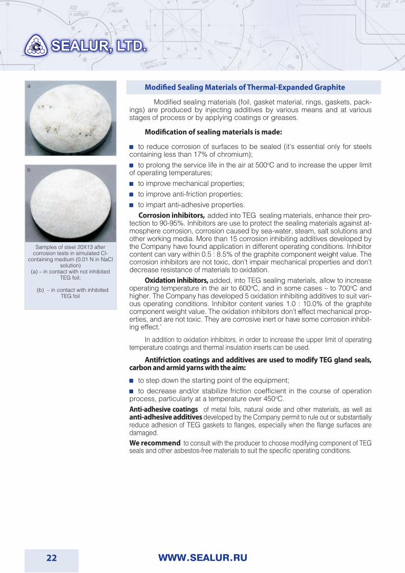
Modi� ed Sealing Materials of Thermal-Expanded Graphite
Modified sealing materials (foil, gasket material, rings, gaskets, pack-ings) are produced by injecting additives by various means and at various stages of process or by applying coatings or greases.
Modi� cation of sealing materials is made:
to reduce corrosion of surfaces to be sealed (it’s essential only for steels containing less than 17% of chromium);
to prolong the service life in the air at 500oC and to increase the upper limit of operating temperatures;
to improve mechanical properties;
to improve anti-friction properties;
to impart anti-adhesive properties.
Corrosion inhibitors, added into TEG sealing materials, enhance their pro-tection to 90-95%. Inhibitors are use to protect the sealing materials against at-mosphere corrosion, corrosion caused by sea-water, steam, salt solutions and other working media. More than 15 corrosion inhibiting additives developed by the Company have found application in different operating conditions. Inhibitor content can vary within 0.5 : 8.5% of the graphite component weight value. The corrosion inhibitors are not toxic, don’t impair mechanical properties and don’t decrease resistance of materials to oxidation.
Oxidation inhibitors, added, into TEG sealing materials, allow to increase operating temperature in the air to 600oC, and in some cases – to 700oC and higher. The Company has developed 5 oxidation inhibiting additives to suit vari-ous operating conditions. Inhibitor content varies 1.0 : 10.0% of the graphite component weight value. The oxidation inhibitors don’t affect mechanical prop-erties, and are not toxic. They are corrosive inert or have some corrosion inhibit-ing effect.’
In addition to oxidation inhibitors, in order to increase the upper limit of operating temperature coatings and thermal insulation inserts can be used.
Antifriction coatings and additives are used to modify TEG gland seals, carbon and armid yarns with the aim:
to step down the starting point of the equipment;
to decrease and/or stabilize friction coefficient in the course of operation process, particularly at a temperature over 450oC.
Anti-adhesive coatings of metal foils, natural oxide and other materials, as well as anti-adhesive additives developed by the Company permit to rule out or substantially reduce adhesion of TEG gaskets to flanges, especially when the flange surfaces are damaged.
We recommend to consult with the producer to choose modifying component of TEG seals and other asbestos-free materials to suit the specific operating conditions.
b
a
Samples of steel 20X13 after corrosion tests in simulated Cl-
containing medium (0.01 N in NaCl solution)
(a) – in contact with not inhibited TEG foil;
(b) – in contact with inhibited TEG foil
23
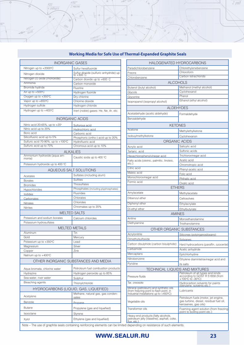
Working Media for Safe Use of Thermal-Expanded Graphite Seals
Nitrogen up to +2000oC
Nitrogen dioxide
Nitrogen (I) oxide (monoxide)
Ammonia
Bromide hydride
Air up to +500oC
Oxygen up to +350oC
Vapor up to +650oC
Нydrogen sulfide
Hydrogen up to +400oC
Nitric acid 20-65%, up to +20o
Nitric acid up to 20%
Boric acid
Silicofluoric acid up to 5%
Sulfuric acid 70-90%, up to +100oC
Sulfuric acid up to 70%
Ammonium hydroxide (aqua am-monia)
Potassium hydroxide up to 400 oC
Acetates
Borates
Bromides
Hypochlorides
Iodides
Carbonates
Nitrates
Nitrites
Potassium and sodium borates
Potassium hydrosulfates
Aluminum
Gold
Potassium up to +350oC
Magnesium
Copper
Natrium up to +400oC
Aqua bromata, chlorine water
Hydrazine
Sea-water, river water
Bleaching agents
Acetylene
Benzole
Butane
Isooctane
Xylol
Paradichlorobenzene
Freons
Chlorobenzene
Butanol (butyl alcohol)
Glycols
Glycerine
Isopropanol (isopropyl alcohol)
Acetaldehyde (acetic aldehyde)
Benzaldehyde
Acetone
Isobuylmethylketone
Acrylic acid
Tartaric acid
Hexachlorophenylvinegar acid
Fatty acids (oleinic, palmitic, linoleic, etc.)
Citric acid
Maleic acid
Monochlorovinegar acid
Formic acid
Amylacetate
Dibenzul ether
Diphenyl ether
Di-ethyl ether
Aniline
Diethylamine
Acrylonitrile
Dimethylsulfoxide
Carbon disulphide (carbon bisulphide)
Carbamide
Mercaptans
Nitrobenzene
Pyridine
Pressure fluids
Tar, creosote
Mineral (petroleum) and synthetic oils (from freezing point to flash point, in industrial installations up to +450oC)
Vegetable oils
Transformer oils
Heavy-end products (fatty alcohols, petroleum jelly (Vaseline), asphalt, coke, flux, etc.)
INORGANIC GASES
HYDROCARBONS (LIQUID, GAS, LIQUEFIED)
HALOGENATED HYDROCARBONS
ALCOHOLS
ALDEHYDES
KETONES
ORGANIC ACIDS
ETHERS
AMINES
OTHER ORGANIC SUBSTANCES
TECHNICAL LIQUIDS AND MIXTURES
INORGANIC ACIDS
ALKALIES
AQUEOUS SALT SOLUTIONS
MELTED SALTS
MELTED METALS
OTHER INORGANIC SUBSTANCES AND MEDIA
Sulfur hexafluoride
Sulfur dioxide (sulfuric anhydride) up to +300�C
Carbon dioxide up to +600�C
Carbon monoxide
Fluorine
Hydrogen fluoride
Dry chlorine
Chlorine dioxide
Hydrogen chloride
Inert (noble) gases: He, Ne, Ar, etc.
Sulfurous acid
Hydrochloric acid
Carbonic acid
Phosphoric (ortho-) acid up to 20%
Hydrofluoric acid
Chromous acid up to 10%
Caustic soda up to 400 oC
Sulfates (including alum)
Sulfites
Thiosulfates
Phosphates (including plyphosphates)
Fluorides
Chlorates
Chlorides
Chromates up to 20%
Calcium chlorides
Tin
Mercury
Lead
Silver
Zink
Petroleum fuel combustion products
Hydrogen peroxide up to 85%
Sulphur
Thionylchloride
Methane, natural gas, gas conden-sates
Propane
Propylene (gas and liquefied)
Styrene
Ethylene (gas and liquefied)
Chlorethylenebenzene
Chloroform
Carbon tetrachloride
Methanol (methyl alcohol)
Cyclohexanol
Phenol
Ethanol (ethyl alcohol)
Formaldehyde
Methylethylketone
Cyclohexanon
Salicylic acid
Sulfonic acids
Trichlorovinegar acid
Acetic acid
Chromotropic acid
Phenyl-acetic acid
Folic acid
Phthalic acid
Oxalic acid
Methylacetate
Cellosolves
Ethylacrylate
Ethylbutyrate
Monoethanolamine
Triethanolamine
Silicones (polyirganosiloxans)
Solixanes
Hard hydrocarbons (paraffin, ozocerite)
Acetic anhydride
Epilchlorhydine
Ethylene diamintetravinegar acid and
its salts
Petroleum of all types and kinds according to GOST R 51858 (from +100oC to -30oC)
Hydrocarbon solvents for paints (benzene, solvents etc.)
Lubricants
Petroleum fuels (motor, jet engine, gas turbine, diesel, residual fuel oil, kerosenes, gas oils)
Foaming agent solution (from freezing point to boiling point etc.)
Note – The use of graphite seals containing reinforcing elements can be limited depending on resistance of such elements.
24
SEALUR, LTD.