Embed Size (px)
Citation preview

7/27/2019 seals1.pdf
http://slidepdf.com/reader/full/seals1pdf 1/6
Mechanical Seals & Packing: Video Based Educational Packages Page 1 of 6
file://C:\WINDOWS\...\Mechanical Seals & Packing Video Based Educational Packages.ht 7/13/03
MECHANICAL SEALS &
PACKING: Getting the job done...
Mechanical Seals: video based educational package produced
by pump people for pump people...
I. The Pump Stuffing Box
1. Stuffing Box Components:
In appreciation of the variables involved in modern process
pumping most manufacturers offer stuffing boxes with ample
room to incorporate packing or mechanical seals with the
ports required for internal or external flush injection, to
utilize auxiliary devices, and jacketing to accommodatetemperature requirements. Knowing how to properly apply
packing, flush arrangements and auxiliary devices will prolong both pump and packing
life.
a. Compression Packing: An understanding of compression packing & the pump stuffing
box will lessen downtime while improving process performance.
b. Throttle & Throat Bushings: The use of throat and throttle bushings will result in a
controlled stuffing box pressure environment which is essential to packing life.
c. Lantern Rings & Seal Cages: Arranged properly lantern rings and seal cages will
contribute to decreasing stuffing box pressure, removal of solids, and sealing between the
packing and pump sleeve on static lift or suction under vacuum conditions.d. Packing Glands: Glands come in a variety of designs each with a specific purpose to
complement a given pumping application.
2. Controlling Box Pressure:
To obtain maximum packing or seal service life it would be desirable
to seal the fluid wishing to escape through the pump stuffing box at
a minimal pressure. To control and reduce the pressure in the
stuffing box centrifugal pump manufacturers will incorporate
balancing holes or pump out vanes in impeller design...
a. Impeller Pump-Out Vanes: To reduce the volume of pumpage attempting to exit astuffing box, pump out vanes are use at the rear of an impeller to reduce the pressure at
flow seen at the stuffing box bore.

7/27/2019 seals1.pdf
http://slidepdf.com/reader/full/seals1pdf 2/6
Mechanical Seals & Packing: Video Based Educational Packages Page 2 of 6
file://C:\WINDOWS\...\Mechanical Seals & Packing Video Based Educational Packages.ht 7/13/03
II. Mechanical Shaft Seals
b. Impeller Balancing Holes: Realizing the pumpage leaves the impeller vane tips and a
portion seeks a path behind an impeller, balancing holes permit a percentage of this fluid
to return to the impeller eye (suction pressure), both reducing bearing loads and reducing
stuffing box pressure.
c. Positive Displacement Pumps: Internal and external porting from discharge to suction to
reduce suction pressure. In many pump designs this recirculation is required to cool and
lubricate tight tolerance sleeve bearings and bushings.
3. Packed Stuffing Box Configurations
Successful packing application depends largely in part to
the proper application of the lantern ring, throttle
bushing and the incorporation of internal and external
flush arrangements. Positioning and control of these
components and auxiliary systems will ensure maximum
pump and packing performance.
a. Abrasive Duty: Suitable packing material combined with proper positioning of the
throttle bushing(s), and lantern ring(s), with flushing where applicable will result in
extended packing and pump life.
b. High Temperature Applications: When faced with high pumpage temperatures stuffing
box and gland cooling is essential. Many fluids will vaporize when seeing the reduction of
pressure within the stuffing box and when exiting to atmosphere. External box cooling and
jacket offer alternatives to control flashing and vaporization.
c. High Pressure Sealing: The use of throttle bushings and lantern rings appropriately
positioned will decrease the volume of fluid wishing to enter the stuffing box resulting in a
reduction of stuffing box pressure. A bleed from a lantern ring to pump suction, whenappropriate, can also reduce and help control stuffing box pressure.
d. Vacuum Conditions:
4. Packing Installation & Troubleshooting
Packing installation and troubleshooting is an art form, rather
engineered science. Only those who thoroughly understand the
application and purpose of the components and auxiliary devices
incorporated into a packed stuffing box arrangement will be able to
effectively apply compression packing.
a. Cut Packing & Installation: While a "no brainer" task to most individuals, cutting
packing is an important contribution to packing life. Remember; a good butt cut is
superior to a poor miter cut, even though miter cut packing is a preferred method.
b. Running-In & Packing Adjustments: With the evolution of mechanical seals and sealless
magnetic drive pumps most individuals capable of performing these tasks correctly have
retired taking their expertise. Most damage to pump sleeves initiates at conception during
start-up after a new or replacement packing task has been completed.
c. Troubleshooting:

7/27/2019 seals1.pdf
http://slidepdf.com/reader/full/seals1pdf 3/6
Mechanical Seals & Packing: Video Based Educational Packages Page 3 of 6
file://C:\WINDOWS\...\Mechanical Seals & Packing Video Based Educational Packages.ht 7/13/03
III. Auxiliary Mechanical Seal Systems
1. Operating Principles & Fundamentals
Since the development of the basic mechanical seal introduction of new
and innovative seal technologies has enabled mechanical seal
installation on virtually any fluid handling application. To sort through
which seal design will provide optimum performance a thoroughunderstanding of mechanical seal principles and fundamentals is
mandatory.
a. Pusher & Non-Pusher Seal Designs: Pusher seals, while generally less expensive than
non-pusher seal designs, will have a tendency to "hang-up" on the pump shaft when
handling fluids which coke or crystallize as the secondary sealing member which must
accommodate for travel as the seal faces wear is unable.
b. Seal Driving & Spring Compression: The rotary portion of a mechanical seal is either
positive or friction drive. Incorporating an improper driving arrangement on a given
application will result in premature and catastrophic failure.
c. Balanced & Unbalanced Seals: This difference in seal design will make the difference inseal performance. An unbalanced mechanical seal seeing high pressures has the fluid film
between the seal faces reduced due to high hydraulic face loading resulting in overheating,
rapid face wear, and premature seal failure.
d. Inside & Outside Seal Mounting: While inside mechanical seals are a preferred method
outside seals can be used when fitting a pump with a shallow stuffing box which cannot
dimensionally accommodate an inside seal.
2. Mechanical Seal Configurations
a. Double Mechanical Seals: When the use of a an appropriate single mechanical seal
becomes to expensive and when the pumpage dictates the use of an artificial sealingenvironment double seals are used as an economical and performance alternative.
b. Seals In Tandem: Carcinogens and other hazardous materials require "zero leakage".
Tandem seals will permit a fail safe seal operating configuration enabling the
implementation of alarms, shut-downs and other warning and safety components.
c. Cartridge Seal Designs: The critical nature of many pump installations prohibits and
limits downtime for seal replacement. Many seals require complex settings during
installation and the time required for proper installation is simply not available. Cartridge
seals accommodate these scenarios by providing the complete seal pre-assembled and
readied for installation offering repair of failed seals at convenience.
3. Fluid Characteristics & Seal Application
a. Process Fluid Behavior: Prior to selecting a mechanical seal it is imperative process fluid
characteristics be identified. In most cases it is the fluid which will determine materials of
construction, seal design, auxiliary components require, etc., to ensure expected seal
performance.
b. Seal Pressure - Velocity Limitations: Mechanical seal designs and seal faces require
cooling and lubrication to function properly. The hydraulic pressure acting on the seal
faces and the rotating speed of the rotary seal will generate heat. It is this seal generated
heat that limits various seal designs and materials.
7/27/2019 seals1.pdf
http://slidepdf.com/reader/full/seals1pdf 4/6
Mechanical Seals & Packing: Video Based Educational Packages Page 4 of 6
file://C:\WINDOWS\...\Mechanical Seals & Packing Video Based Educational Packages.ht 7/13/03
IV. Mechanical Seal Troubleshooting & Failure Analysis
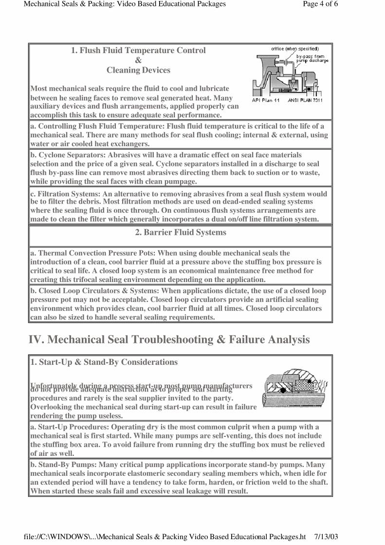
1. Flush Fluid Temperature Control&
Cleaning Devices
Most mechanical seals require the fluid to cool and lubricate
between he sealing faces to remove seal generated heat. Manyauxiliary devices and flush arrangements, applied properly can
accomplish this task to ensure adequate seal performance.
a. Controlling Flush Fluid Temperature: Flush fluid temperature is critical to the life of a
mechanical seal. There are many methods for seal flush cooling; internal & external, using
water or air cooled heat exchangers.
b. Cyclone Separators: Abrasives will have a dramatic effect on seal face materials
selection and the price of a given seal. Cyclone separators installed in a discharge to seal
flush by-pass line can remove most abrasives directing them back to suction or to waste,
while providing the seal faces with clean pumpage.
c. Filtration Systems: An alternative to removing abrasives from a seal flush system wouldbe to filter the debris. Most filtration methods are used on dead-ended sealing systems
where the sealing fluid is once through. On continuous flush systems arrangements are
made to clean the filter which generally incorporates a dual on/off line filtration system.
2. Barrier Fluid Systems
a. Thermal Convection Pressure Pots: When using double mechanical seals the
introduction of a clean, cool barrier fluid at a pressure above the stuffing box pressure is
critical to seal life. A closed loop system is an economical maintenance free method for
creating this trifocal sealing environment depending on the application.
b. Closed Loop Circulators & Systems: When applications dictate, the use of a closed loop
pressure pot may not be acceptable. Closed loop circulators provide an artificial sealing
environment which provides clean, cool barrier fluid at all times. Closed loop circulators
can also be sized to handle several sealing requirements.
1. Start-Up & Stand-By Considerations
Unfortunately during a process start-up most pump manufacturersdo not provide adequate instruction as to proper seal starting
procedures and rarely is the seal supplier invited to the party.
Overlooking the mechanical seal during start-up can result in failure
rendering the pump useless.
a. Start-Up Procedures: Operating dry is the most common culprit when a pump with a
mechanical seal is first started. While many pumps are self-venting, this does not include
the stuffing box area. To avoid failure from running dry the stuffing box must be relieved
of air as well.
b. Stand-By Pumps: Many critical pump applications incorporate stand-by pumps. Many
mechanical seals incorporate elastomeric secondary sealing members which, when idle for
an extended period will have a tendency to take form, harden, or friction weld to the shaft.
When started these seals fail and excessive seal leakage will result.

7/27/2019 seals1.pdf
http://slidepdf.com/reader/full/seals1pdf 5/6
Mechanical Seals & Packing: Video Based Educational Packages Page 5 of 6
file://C:\WINDOWS\...\Mechanical Seals & Packing Video Based Educational Packages.ht 7/13/03
2. Identifying Premature Failure & Corrective Actions
As with any piece of process equipment to avoid recurring failure and down time it isimperative the cause of the failure be addressed not merely the symptoms. Scrutinizing the
physical characteristics of failed seal faces and components will uncover the culprit and
assist in determining the corrective actions to be taken.
a. Chemical Attack: Leaves the parts appearing dull, honey combed, flaky, or starting tocrumble or break up. Weight and material hardness readings taken on the damaged parts
will be substantially lower than readings on the original parts.
b. Fretting Corrosion: One of the most common types of corrosion encountered in
mechanical seals. It only causes leakage at the secondary seals but damages the sleevedirectly beneath the secondary seal area. This area will appear pitted and shiny bright.
c. Leaching: Normally causes a minor increase in seal leakage and a large increase in the
wear of carbon faces. Ceramic and tungsten carbide faces that have been leached will
appear dull and matted, even though no coating is present on them
d. Erosion: Seal face may be eaten away or washed-out in one localized area. Erosion will
commonly occur on a stationary seal face until seal face distortion or break down occurs.
e. Heat Checking: Is indicated by the presence of fine to large cracks that seem to radiate
from the center of the seal face. These cracks act as a series of cutting and scraping edges
against carbon graphite and other seal face materials.
f. Vaporization: Any popping, puffing, or blowing of vapors at the seal faces is evidence of
vaporization. Vaporization does not frequently cause catastrophic failure, but it usuallyshortens seal life. Inspection of the seal faces reveals signs of chipping at the inside and
outside diameters and pitting over the entire area.
g. Oxidation & Coking: Leaves a varnish, a lacquer, or an abrasive sludge on the
atmospheric side of the seal. This can cause rapid wear of the seal faces or hang-up in both
pusher and non-pusher types of mechanical seals.
Other Pump & Seal Related Courses...
Process & Industrial Training Technologies6022 Harrison Ave., #3Cincinnati, Ohio 45248
Ph(513) 574-1666 | Fax (513) 574-1358
Return main menu "Pumps & Filtration On-Line"
Additional Information
"Pumps & Filtration On-Line" © 1996 is a publication of Process & Industrial Training Technologies, Inc., Cincinnati, Ohio. The material
presented within this site is for educational and information purposes only and the publisher makes no claim to warranty (expressed or
implied) to its content nor the validity of advertisement, articles, and opinions expressed by the authors. Microsoft Internet Explorer ©1996
Course Components
Component Pricing & On-Line Order Form

7/27/2019 seals1.pdf
http://slidepdf.com/reader/full/seals1pdf 6/6
Mechanical Seals & Packing: Video Based Educational Packages Page 6 of 6
fil //C \WINDOWS\ \M h i l S l & P ki Vid B d Ed ti l P k ht 7/13/03
Microsoft and/or its suppliers, All rights reserved.